US10466016B2 - Ballistic shield - Google Patents
Ballistic shieldDownload PDFInfo
- Publication number
- US10466016B2 US10466016B2US15/973,450US201815973450AUS10466016B2US 10466016 B2US10466016 B2US 10466016B2US 201815973450 AUS201815973450 AUS 201815973450AUS 10466016 B2US10466016 B2US 10466016B2
- Authority
- US
- United States
- Prior art keywords
- shield
- supporting surface
- barrier
- planar portion
- side wall
- Prior art date
- Legal status (The legal status is an assumption and is not a legal conclusion. Google has not performed a legal analysis and makes no representation as to the accuracy of the status listed.)
- Active
Links
- 230000004888barrier functionEffects0.000claimsabstractdescription129
- 230000014759maintenance of locationEffects0.000description46
- 238000002955isolationMethods0.000description8
- 229920000049Carbon (fiber)Polymers0.000description6
- 239000004917carbon fiberSubstances0.000description6
- -1masonrySubstances0.000description6
- 239000000463materialSubstances0.000description6
- 239000002184metalSubstances0.000description6
- VNWKTOKETHGBQD-UHFFFAOYSA-NmethaneChemical compoundCVNWKTOKETHGBQD-UHFFFAOYSA-N0.000description6
- 238000000034methodMethods0.000description6
- 230000000149penetrating effectEffects0.000description6
- 230000008901benefitEffects0.000description4
- 230000003100immobilizing effectEffects0.000description2
- 238000012986modificationMethods0.000description2
- 230000004048modificationEffects0.000description2
- 208000027418Wounds and injuryDiseases0.000description1
- 230000006378damageEffects0.000description1
- 238000004880explosionMethods0.000description1
- 208000014674injuryDiseases0.000description1
- 238000009434installationMethods0.000description1
Images


Classifications
- F—MECHANICAL ENGINEERING; LIGHTING; HEATING; WEAPONS; BLASTING
- F41—WEAPONS
- F41H—ARMOUR; ARMOURED TURRETS; ARMOURED OR ARMED VEHICLES; MEANS OF ATTACK OR DEFENCE, e.g. CAMOUFLAGE, IN GENERAL
- F41H5/00—Armour; Armour plates
- F41H5/013—Mounting or securing armour plates
- F—MECHANICAL ENGINEERING; LIGHTING; HEATING; WEAPONS; BLASTING
- F41—WEAPONS
- F41H—ARMOUR; ARMOURED TURRETS; ARMOURED OR ARMED VEHICLES; MEANS OF ATTACK OR DEFENCE, e.g. CAMOUFLAGE, IN GENERAL
- F41H5/00—Armour; Armour plates
- F41H5/06—Shields
- F—MECHANICAL ENGINEERING; LIGHTING; HEATING; WEAPONS; BLASTING
- F41—WEAPONS
- F41H—ARMOUR; ARMOURED TURRETS; ARMOURED OR ARMED VEHICLES; MEANS OF ATTACK OR DEFENCE, e.g. CAMOUFLAGE, IN GENERAL
- F41H5/00—Armour; Armour plates
- F41H5/06—Shields
- F41H5/12—Shields for smallarms; for light-rocket launchers
- F41H5/14—Wheeled armoured shields
Definitions
- Applicantdiscloses a ballistic shield for use with barrier systems.
- the shieldis movable between an extended position and a retracted position relative to a front wall of a barrier to which the shield is attached.
- the shieldIn the extended position, the shield extends from the supporting surface to at least a height of a lower edge of the front wall of the barrier.
- the shieldprovides protection from projectiles including ballistics and/or spall that might enter a gap between the front wall and the supporting surface.
- the shieldIn the retracted position, the shield is retracted relative to the supporting surface and thereby provides clearance to facilitate movement of the barrier.
- the front wall of the barrierextends in a substantially upward direction relative to a supporting surface and comprises a lower edge and an upper edge.
- the barriermay further comprise a first side wall that extends at an angle from the front wall and extends upward from the supporting surface.
- a second side wallmay extend at an angle from the front wall and extend upward from the supporting surface.
- the first side wall and the second side wallextend substantially perpendicular to the front wall and substantially parallel to each other.
- the barriermay be mounted on wheel systems such as casters. Mounting on the wheel systems may result in the bottom edge of the front wall being spaced apart from the supporting surface. In other words, a gap may be formed between the lower edge of the front wall and the supporting surface.
- the shieldis movably attached to the first side wall and the second side wall.
- the shieldis movable relative to the side walls between the extended position and the retracted position.
- the shieldIn the extended position, the shield is positioned to abut the supporting surface and extends upward from adjacent the supporting surface to a height at least equal to a height of the gap formed between the lower edge of the front wall and the supporting surface.
- the shieldIn the retracted position, the shield is withdrawn relative to the supporting surface.
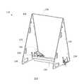
- FIG. 1Adepicts a rear perspective view of an example barrier with a shield in an extended position.
- FIG. 1Bdepicts an isolated rear perspective view of an example barrier with a shield in an extended position.
- FIG. 1Cdepicts a side view of an example barrier with a shield in an extended position.
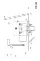
- FIG. 1Ddepicts a side view, partially in transparency, of an example barrier with a shield in an extended position.
- FIG. 1Edepicts a top view of an example barrier with a shield in an extended position.
- FIG. 1Fdepicts a front view of an example barrier with a shield in an extended position.
- FIG. 2Adepicts a rear perspective view of an example barrier with a shield in an extend position.
- FIG. 2Bdepicts an isolated rear perspective view of an example barrier with a shield in an extended position.
- FIG. 2Cdepicts a side view of an example barrier with a shield in an extended position.
- FIG. 2Ddepicts a side view, partially in transparency, of an example barrier with a shield in an extended position.
- FIG. 2Edepicts a top view of an example barrier with a shield in an extended position.
- FIG. 2Fdepicts a front view of an example barrier with a shield in an extended position.
- FIG. 3Adepicts a rear perspective view of an example barrier with a shield in a retracted position.
- FIG. 3Bdepicts an isolated rear perspective view of an example barrier with a shield in a retracted position.
- FIG. 3Cdepicts a side view of an example barrier with a shield in a retracted position.
- FIG. 3Ddepicts a side view, partially in transparency, of an example barrier with a shield in a retracted position.
- FIG. 3Edepicts a top view of an example barrier with a shield in a retracted position.
- FIG. 3Fdepicts a front view of an example barrier with a shield in a retracted position.
- FIG. 4Adepicts a rear perspective view of an example shield in isolation.
- FIG. 4Bdepicts a rear view of an example shield in isolation.
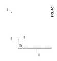
- FIG. 4Cdepicts a side view of an example shield in isolation.
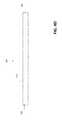
- FIG. 4Ddepicts a front view of an example shield in isolation.
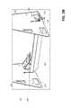
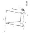
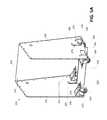
- FIG. 5Adepicts a rear perspective view of an example barrier with a shield in an extended position.
- FIG. 5Bdepicts an isolated rear perspective view of an example barrier with a shield in an extended position.
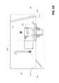
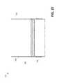
- FIG. 5Cdepicts a side view of an example barrier with a shield in an extended position.
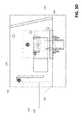
- FIG. 5Ddepicts a side view, partially in transparency, of an example barrier with a shield in an extended position.
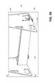
- FIG. 5Edepicts a top view of an example barrier with a shield in an extended position.
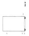
- FIG. 5Fdepicts a front view of an example barrier with a shield in an extended position.
- FIG. 6Adepicts a rear perspective view of an example barrier with a shield in an extend position.
- FIG. 6Bdepicts an isolated rear perspective view of an example barrier with a shield in an extended position.
- FIG. 6Cdepicts a side view of an example barrier with a shield in an extended position.
- FIG. 6Ddepicts a side view, partially in transparency, of an example barrier with a shield in an extended position.
- FIG. 6Edepicts a top view of an example barrier with a shield in an extended position.
- FIG. 6Fdepicts a front view of an example barrier with a shield in an extended position.
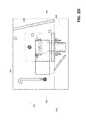
- FIG. 7Adepicts a rear perspective view of an example barrier with a shield in a retracted position.
- FIG. 7Bdepicts an isolated rear perspective view of an example barrier with a shield in a retracted position.
- FIG. 7Cdepicts a side view of an example barrier with a shield in a retracted position.
- FIG. 7Ddepicts a side view, partially in transparency, of an example barrier with a shield in a retracted position.
- FIG. 7Edepicts a top view of an example barrier with a shield in a retracted position.
- FIG. 7Fdepicts a front view of an example barrier with a shield in a retracted position.
- FIG. 8Adepicts a rear perspective view of an example shield in isolation.
- FIG. 8Bdepicts a rear view of an example shield in isolation.
- FIG. 8Cdepicts a side view of an example shield in isolation.
- FIG. 8Ddepicts a front view of an example shield in isolation.
- the barriermay comprise a front wall having a lower edge and an upper edge.
- the front wallextends in a substantially upward direction relative to a supporting surface, with the lower edge spaced apart from the supporting surface.
- the retractable shieldmay be moved between an extended position and a retracted position relative to the barrier. In the extended position, the shield extends from the supporting surface to at least a height of a lower edge of a front wall of the shield. In the extended position, the shield provides protection in an area corresponding to any gap between the front wall and the supporting surface. In the retracted position, the shield is removed relative to the supporting surface and provides clearance which might facilitate movement of the barrier.
- FIGS. 1A-1Fdepict an example barrier system with a shield in an extended position.
- barrier 110comprises a front wall 120 having a lower edge 122 and an upper edge 124 .
- the front wallextends in a substantially upward direction relative to the supporting surface 114 .
- Front wallis adapted to prevent projectiles that strike the first side of the front wall from penetrating through to the second side.
- front wall 120may be an armored panel or wall formed from materials such as metal, masonry, and/or carbon fiber capable of withstanding ballistics and blast projectiles.
- Side panels or walls 130 and 132extend from front wall 124 and operate to stabilize front panel 124 and maintain barrier 110 in an upright position.
- Side walls 130 and 132extend upward from supporting surface 114 and are rigidly coupled to front wall 124 .
- front wall 124leans toward side walls 130 and 132 such that at least part of the weight of front wall 124 is supported by side walls 130 and 132 .
- Side walls 130 and 132extend upward from lower edges 138 and 139 , respectively. In an example embodiment, a portion of lower edges 138 and 139 may contact supporting surface 114 .
- Side walls 130 and 132are adapted to prevent projectiles that strike the walls from penetrating from an exterior first side through to a protected second side.
- side walls 130 and 132may be an armored panel or wall formed from materials such as metal, masonry, and/or carbon fiber capable of withstanding ballistics and blast projectiles.
- barrier 110further comprises wheel systems 140 and 142 which facilitate movement of barrier 110 .
- wheel systems 140 and 142may be casters with wheels that swivel.
- Wheel systems 140 and 142may be attached to side walls 130 and 132 , respectively, in proximity to the location that side walls 130 and 132 are attached to front wall 124 .
- Wheel systems 140 and 142extend below lower edges 138 and 139 of side walls 130 and 132 and below lower edge 122 of front wall 124 . Wheels that are part of wheel systems 140 and 142 contact supporting surface 114 and support at least a portion of the weight of barrier 110 . When wheels of wheel systems 130 and 132 contact supporting surface 114 , a gap is formed between the supporting surface and the lower edges 122 , 138 , and 139 .
- Barrier 110further comprises shield 150 which is adapted to be moved between an extended position and a retracted position.
- shield 150In an extended position, as illustrated in FIGS. 1A-F and 2 A-F, shield 150 abuts supporting surface 114 and extends upward from adjacent supporting surface 114 to a height at least equal to gap 160 formed between lower edge 122 of front wall 124 and supporting surface 114 .
- shield 150In a retracted position, as illustrated in FIGS. 3A-F , shield 150 is withdrawn relative to the supporting surface.
- shield 150comprises a first planar portion 152 and a second planar portion 154 .
- Second planar portion 154intersects with and extends from first planar portion 152 at an angle, which may be, for example, an approximately ninety (90) degree angle.
- first planar portion 152is longer than second planar portion 154 .
- Shield 150is adapted to prevent projectiles that strike panels 152 and 154 from penetrating from an exterior first side through to a protected second side.
- shield 150may be armored and formed from materials such as metal, masonry, and/or carbon fiber capable of withstanding ballistics and blast projectiles.
- Shield 150further comprises a first retention member 156 and a second retention member 158 which extend from opposing sides of shield 150 .
- retention members 156 and 158extend from opposing sides of shield proximate the location the first planar portion 152 and second planar portion 154 intersect.
- Retention members 156 and 158are received in corresponding recesses 134 and 136 formed in side walls 130 and 132 .
- Recesses 134 and 136may be elongated and extend upward from a location proximate bottom edges 138 and 139 of side walls 130 and 132 , to a location further removed or remote from bottom edges 138 and 139 .
- retention members 156 and 158are located at or near the portion of recesses 134 and 136 closest to bottom edges 138 and 139 . As illustrated in FIGS. 3A-F , when shield 150 is in its retracted position, retention members 156 and 158 are in recesses 134 and 136 , but are removed to a location relatively remote from lower edges 138 and 139 of side walls. It will be appreciated that retention members 156 and 158 may travel within recesses 134 and 136 in response to forces applied to shield 150 and/or barrier 110 . It will be appreciated that retention members 156 and 158 are pivotally moveable relative to recesses 134 and 136 . Accordingly, shield 150 may be pivoted about retention members 156 and 158 , which may pivot within recesses 134 and 136 .
- First planar portion 152 of shield 150extends between side walls 130 and 132 and slopes downward from a height corresponding to the location of retention members 156 and 158 in recesses 134 and 136 to a position adjacent to supporting surface 114 . As illustrated in FIGS. 1A-F , first planar portion 152 may be positioned to slope down and away relative to front wall 120 . Second planar portion 154 extends at approximately a ninety-degree angle to first planar portion 152 and extends downward and toward front wall 120 . In the position shown in FIGS. 1A-F , barrier 110 may be moved forward while shield 150 is in its extended position. The sloping arrangement of first planar portion 152 accommodates movement of the shield over supporting surface 114 in instances when barrier 110 is moved forward.
- first planar portion 152assumes an increasingly steep angle relative to supporting surface 114 . If movement of barrier 110 relative to shield 150 continues, first planar portion 152 may assume a position wherein it slopes toward front wall 120 as illustrated in FIGS. 2A-F .
- first planar portion 152may be positioned to extend from its location in recesses 134 and 136 toward supporting surface 114 .
- First planar portion 152slopes down and toward front wall 120 .
- barrier 110may be moved backward while shield 150 is in its extended position.
- the sloping arrangement of first planar portion 152accommodates movement of shield 150 over supporting surface 114 when barrier 110 is moved backward.
- shield 150may remain substantially in a fixed position relative to the remainder of barrier 110 due to friction between shield 150 and supporting surface 114 .
- Retention members 156 and 158slide upward in recesses 134 and 136 as shield 150 remains substantially in a fixed position relative to the remainder of barrier 110 .
- first planar portion 152assumes an increasingly steep angle relative to supporting surface 114 . If movement of barrier 110 relative to shield 150 continues, first planar portion 152 may assume a position wherein it slopes away from front wall 120 as illustrated in FIGS. 1A-F . It will be appreciated that shield 150 may move between positions illustrated in FIGS. 1A-F and FIGS. 2A-F as barrier 110 is moved forward and backward. In both positions, shield 150 provides protection from projectiles and spall that may enter upon a gap 160 between lower edge 122 of front wall 120 and supporting surface 114 .
- FIGS. 3A-Fillustrate shield 150 in a retracted position.
- retention members 156 and 158are positioned in recesses 134 and 136 at a position relatively remote from bottom edges 138 and 139 of side walls 130 and 132 .
- recesses 134 and 136may be configured to maintain retention members 156 and 158 at a location in the recesses remote from bottom edges 138 and 139 .
- recesses 134 and 136extend upward, curve, and terminate in an area 170 that is adapted to support and at least partially immobilize or secure retention members 156 and 158 at a location within recesses 134 and 136 .
- first planar portion 152extends downward substantially perpendicular to supporting surface 114 .
- first planar portion 152is raised above supporting surface 114 . Accordingly, in the retracted position, shield 150 provides clearance to accommodate movement of barrier 110 in any direction without any interference by or movement of shield 150 .
- shield 150may be positioned as in FIGS. 3A-F by manual human intervention.
- FIGS. 5A-F , 6 A-F, 7 A-F, and 8 A-Ddepict another example barrier system with shield.
- the barrier system depicted in FIGS. 5-8operates similarly to those systems described above, but comprises additional features.
- the barrier system depicted in FIGS. 5-8comprises additional wheel systems 244 and 246 which facilitate mobility.
- Side walls 230 and 232may have a different configuration or shape as compared to the sidewalls described in connection with FIGS. 1-3 .
- recesses 234 and 236have a different configuration as compared to recesses 134 and 136 depicted in FIGS. 1-3 . More particularly, recesses 234 and 236 comprise enlarged areas 280 and 282 , respectively, adapted to be used in mounting shield 250 within recesses 234 and 236 .
- FIGS. 5A-Fdepict an example barrier system with a shield in an extended position.
- barrier 210comprises a front wall 220 having a lower edge 222 and an upper edge 224 .
- the front wallextends in a substantially upward direction relative to the supporting surface 214 .
- Front wallis adapted to prevent projectiles that strike the first side of the front wall from penetrating through to the second side.
- front wall 220may be an armored panel or wall formed from materials such as metal, masonry, and/or carbon fiber capable of withstanding ballistics and blast projectiles.
- Side panels or walls 230 and 232extend from front wall 220 and operate to stabilize front panel 224 and maintain barrier 210 in an upright position.
- Side walls 230 and 232extend upward from supporting surface 214 and are rigidly coupled to front wall 224 .
- front wall 224leans toward side walls 230 and 232 such that at least part of the weight of front wall 224 is supported by side walls 230 and 232 .
- Side walls 230 and 232extend upward from lower edges 238 and 239 , respectively.
- Side walls 230 and 232are adapted to prevent projectiles that strike the walls from penetrating from an exterior first side through to a protected second side.
- side walls 230 and 232may be an armored panel or wall formed from materials such as metal, masonry, and/or carbon fiber capable of withstanding ballistics and blast projectiles.
- barrier 210further comprises wheel systems 240 , 242 , 244 , and 246 which facilitate movement of barrier 110 .
- wheel systems 240 , 242 , 244 , and 246may be casters with wheels that swivel.
- Wheel systems 240 , 242 , 244 , and 246may be attached to side walls 230 and 232 in any suitable manner.
- wheel systems 240 , 242 , 244 , and 246may form brackets that receive side walls therein and form a frictional fit with the side walls.
- wheel systems 240 , 242 , 244 , and 246may be attached to barrier 210 so as to be easily removed, possibly without use of tools.
- Wheel systems 240 , 242 , 244 , and 246extend below lower edges 238 and 239 of side walls 230 and 232 and below lower edge 222 of front wall 224 . Wheels that are part of wheel systems 240 , 242 , 244 , and 246 contact supporting surface 214 and support at least a portion of the weight of barrier 210 . When wheels of wheel systems 230 and 232 contact supporting surface 214 , a gap is formed between the supporting surface and the lower edges 222 , 238 , and 239 .
- Barrier 210further comprises shield 250 which is adapted to be moved between an extended position and a retracted position.
- shield 250In an extended position, as illustrated in FIGS. 5A-F and 6 A-F, shield 250 abuts supporting surface 214 and extends upward from adjacent supporting surface 214 to a height at least equal to gap 260 formed between lower edge 222 of front wall 224 and supporting surface 214 .
- shield 250In a retracted position, as illustrated in FIGS. 7A-F , shield 250 is withdrawn relative to the supporting surface.
- shield 250comprises a first planar portion 252 and a second planar portion 254 .
- Second planar portion 254intersects with and extends from first planar portion 252 at an angle, which may be, for example, an approximately ninety (90) degree angle.
- first planar portion 252is longer than second planar portion 254 .
- Shield 250is adapted to prevent projectiles that strike panels 252 and 254 from penetrating from an exterior first side through to a protected second side.
- shield 250may be armored and formed from materials such as metal, masonry, and/or carbon fiber capable of withstanding ballistics and blast projectiles.
- Shield 250further comprises a first retention member 256 and a second retention member 258 which extend from opposing sides of shield 250 .
- retention members 256 and 258extend from opposing sides of shield proximate the location the first planar portion 252 and second planar portion 254 intersect.
- Retention members 256 and 258are received in corresponding recesses 234 and 236 formed in side walls 230 and 232 .
- Recesses 234 and 236may be elongated and extend upward from a location proximate bottom edges 238 and 239 of side walls 230 and 232 , to a location further removed or remote from bottom edges 238 and 239 .
- retention members 256 and 258When shield 250 is in the extended position abutting supporting surface 214 , retention members 256 and 258 are located at or near the portion of recesses 234 and 236 closest to bottom edges 238 and 239 . As illustrated in FIGS. 7A-F , when shield 250 is in its retracted position, retention members 256 and 258 are in recesses 234 and 236 , but are removed to a location relatively remote from lower edges 238 and 239 of side walls. It will be appreciated that retention members 256 and 258 may travel within recesses 234 and 236 in response to forces applied to shield 250 and/or barrier 210 . Retention members 256 and 258 may be pivotally moveable relative to recesses 234 and 236 . Accordingly, shield 250 may be pivoted about retention members 256 and 258 , which may pivot within recesses 234 and 236 .
- First planar portion 252 of shield 250extends between side walls 230 and 232 and slopes downward from a height corresponding to the location of retention members 256 and 258 in recesses 234 and 236 to a position adjacent to supporting surface 214 . As illustrated in FIGS. 5A-F , first planar portion 252 may be positioned to slope down and away relative to front wall 220 . Second planar portion 254 extends at approximately a ninety-degree angle to first planar portion 252 and extends downward and toward front wall 220 . In the position shown in FIGS. 5A-F , barrier 110 may be moved forward while shield 150 is in its extended position.
- first planar portion 252accommodates movement of the shield over supporting surface 214 in instances when barrier 210 is moved forward. If barrier 210 is moved backward while shield 250 is positioned as in FIGS. 5A-F , the motion of shield 250 may be impeded by friction with supporting surface 214 . In such a scenario, shield 250 may remain substantially in a fixed position relative to the remainder of barrier 210 . Retention members 256 and 258 slide upward in recesses 234 and 236 as shield 250 remains substantially in a fixed position relative to the remainder of barrier 210 which may move backward. As retention members 256 and 258 slide upward in recesses 234 and 236 , first planar portion 252 assumes an increasingly steep angle relative to supporting surface 214 . If movement of barrier 210 relative to shield 250 continues, first planar portion 252 may assume a position wherein it slopes toward front wall 220 as illustrated in FIGS. 6A-F .
- first planar portion 252may be positioned to extend from its location in recesses 234 and 236 toward supporting surface 214 .
- First planar portion 252slopes down and toward front wall 220 .
- barrier 210may be moved backward while shield 250 is in its extended position.
- the sloping arrangement of first planar portion 252accommodates movement of shield 250 over supporting surface 214 when barrier 210 is moved backward.
- shield 250may remain substantially in a fixed position relative to the remainder of barrier 210 due to friction between shield 250 and supporting surface 214 .
- Retention members 256 and 258slide upward in recesses 234 and 236 as shield 250 remains substantially in a fixed position relative to the remainder of barrier 210 .
- first planar portion 252assumes an increasingly steep angle relative to supporting surface 214 . If movement of barrier 210 relative to shield 250 continues, first planar portion 252 may assume a position wherein it slopes away from front wall 220 as illustrated in FIGS. 5A-F . It will be appreciated that shield 250 may move between positions illustrated in FIGS. 5A-F and FIGS. 6A-F as barrier 210 is moved forward and backward. In both positions, shield 250 provides protection from projectiles and spall that may enter upon a gap 260 between lower edge 222 of front wall 220 and supporting surface 214 .
- FIGS. 7A-Fillustrate shield 250 in a retracted position.
- retention members 256 and 258are positioned in recesses 234 and 236 at a position relatively remote from bottom edges 238 and 239 of side walls 230 and 232 .
- recesses 234 and 236may be configured to maintain retention members 256 and 258 at a location in the recesses remote from bottom edges 238 and 239 .
- recesses 234 and 236extend upward, curve, and terminate in an area 270 that is adapted to support and at least partially immobilize or secure retention members 256 and 258 at a location within recesses 234 and 236 .
- shield 250By fixing or immobilizing retention members 256 and 258 in area 270 , the entirety of shield 250 is fixed vertically relative to the remainder of barrier 220 .
- first planar portion 252extends downward substantially perpendicular to supporting surface 214 .
- first planar portion 252is raised above supporting surface 214 .
- shield 250provides clearance to accommodate movement of barrier 210 in any direction without any interference by or movement of shield 250 .
- shield 250may be positioned as in FIGS. 7A-F by manual human intervention.
- Recesses 234 and 236comprise mounting areas 280 and 282 , respectively.
- Mounting areas 280 and 282are adapted to facilitate mounting retention members 256 and 258 within recesses 234 and 236 .
- mounting areas 280 and 282may be sized so that the retention members 256 and 258 may be easily positioned in recesses 234 and 236 .
- Retention members 256 and 258may be positioned in recesses 234 and 236 , for example, when mounting shield 250 to barrier 210 , and when removing shield 250 from barrier 210 .
- Mounting area 280may be sized so that retention member 256 may be moved into and out of engagement with the first side wall 230 .
- mounting area 282may be sized so that retention member 258 may be moved into and out of engagement with the second side wall 232 .
- mounting areas 280 and 282may have a rectangular shape with a profile that can easily accommodate retention members 256 and 258 .
- Shield 250may be mounted to the barrier system by positioning retention members 256 and 258 in mounting areas 280 and 282 and then moving retention members 256 and 258 into a narrower section of recesses 234 and 236 .
- Shield 250may be removed from the barrier system by moving shield 250 so that retention members 256 and 258 are removed from the narrower portion of recesses 234 and 236 and positioned within mounting areas 280 and 282 .
- Mounting areas 280 and 282are sized so as to provide clearance for retention members 256 and 258 to be removed from recesses 234 and 236 and thereby remove shield 250 from barrier 210 .
- Mounting areas 280 and 282may be formed at any suitable location within recesses 234 and 236 .
- mounting areas 280 and 282may be positioned at a distal end of recesses 234 and 236 respectively.
- the configuration of recesses 234 and 236 and mounting areas 280 and 282may allow for securing of shield 250 to barrier 210 with ease.
- the arrangement and size of mounting areas 280 and 282may allow for shield 250 to be mounted to, and removed from barrier system 210 without use of additional hardware or tools.
- Applicanthas disclosed a retractable shield for use with a defensive barrier.
- the shieldthat is movable between an extended position and a retracted position.
- the shieldIn the extended position, the shield extends from the supporting surface to at least a height of a lower edge of a front wall of the shield.
- the shieldIn the extended position, the shield provides protection in an area corresponding to any gap between the front wall and the supporting surface.
- the shieldIn the retracted position, the shield is removed relative to the supporting surface and provides clearance from the supporting surface which might facilitate movement of the barrier.
- the shieldhas been described in the context of the example embodiments depicted in the figures, the potential embodiments is not limited to those depicted.
- the shieldmay be employed with barrier systems of all types and configurations which may or may not be as depicted in the figures. Modifications may be made to the shield and the manner of interfacing with the barrier system depending upon the configuration of the particular barrier system.
Landscapes
- Engineering & Computer Science (AREA)
- General Engineering & Computer Science (AREA)
- Aiming, Guidance, Guns With A Light Source, Armor, Camouflage, And Targets (AREA)
Abstract
Description
Claims (18)
Priority Applications (1)
| Application Number | Priority Date | Filing Date | Title |
|---|---|---|---|
| US15/973,450US10466016B2 (en) | 2017-06-01 | 2018-05-07 | Ballistic shield |
Applications Claiming Priority (2)
| Application Number | Priority Date | Filing Date | Title |
|---|---|---|---|
| US201762513735P | 2017-06-01 | 2017-06-01 | |
| US15/973,450US10466016B2 (en) | 2017-06-01 | 2018-05-07 | Ballistic shield |
Publications (2)
| Publication Number | Publication Date |
|---|---|
| US20190033040A1 US20190033040A1 (en) | 2019-01-31 |
| US10466016B2true US10466016B2 (en) | 2019-11-05 |
Family
ID=65137920
Family Applications (1)
| Application Number | Title | Priority Date | Filing Date |
|---|---|---|---|
| US15/973,450ActiveUS10466016B2 (en) | 2017-06-01 | 2018-05-07 | Ballistic shield |
Country Status (1)
| Country | Link |
|---|---|
| US (1) | US10466016B2 (en) |
Families Citing this family (2)
| Publication number | Priority date | Publication date | Assignee | Title |
|---|---|---|---|---|
| US20180274887A1 (en)* | 2017-03-27 | 2018-09-27 | Shieldpro, Llc | Anti-ballistic podium and applications thereof |
| US10859347B1 (en)* | 2019-12-13 | 2020-12-08 | Joseph B Trampenau | Civilian bullet-proof shield |
Citations (85)
| Publication number | Priority date | Publication date | Assignee | Title |
|---|---|---|---|---|
| DE64291C (en) | V. PERRIN in Spandau | Fahrbahrer armor | ||
| US772055A (en) | 1904-01-22 | 1904-10-11 | Ezra L Post | Clutch for leather-stretching machines. |
| FR462049A (en) | 1912-11-12 | 1914-01-17 | Louis Preneron | Protective shield for police officers |
| US1253964A (en) | 1917-04-03 | 1918-01-15 | John A Hack | Guard-house. |
| US1261518A (en) | 1915-08-13 | 1918-04-02 | Martin J Hahre | Movable shield. |
| US1274721A (en) | 1918-03-23 | 1918-08-06 | Anton Krzan | Movable fort. |
| US1281400A (en)* | 1918-04-08 | 1918-10-15 | Johan Hillmer Larnell | Shield. |
| US1327464A (en) | 1919-08-28 | 1920-01-06 | British Ever Ready Company Ltd | Apparatus for playing a game of skill |
| US1465042A (en) | 1921-04-16 | 1923-08-14 | Anthony S Hruska | Carbon holder for picture projectors |
| US1875488A (en) | 1932-09-06 | Cabinet | ||
| US2209654A (en)* | 1938-05-02 | 1940-07-30 | Jr Oscar Loeser | Mobile shield |
| US2370596A (en)* | 1942-03-23 | 1945-02-27 | Earl J Wallace | Portable protective armor device |
| US2613243A (en) | 1948-11-05 | 1952-10-07 | Oscar W S Frear | Safety ground clamp |
| US2845153A (en) | 1954-04-26 | 1958-07-29 | Protex Weatherstrip Mfg Co | Window structures |
| US2878054A (en) | 1956-07-19 | 1959-03-17 | Peter J Linder | Motor vehicle body |
| US2937602A (en) | 1959-09-18 | 1960-05-24 | Isaac S Norris | Bank teller's protective device |
| US2985174A (en) | 1957-12-02 | 1961-05-23 | Oravisual Company Inc | Paper pad clamping fixture |
| US3039161A (en) | 1960-08-29 | 1962-06-19 | Paul L Gagnon | Clamp |
| US3590685A (en) | 1969-02-19 | 1971-07-06 | United Aircraft Prod | Mobile revetment |
| US3712005A (en) | 1969-12-15 | 1973-01-23 | Aztec Mfg Co | Extrusions for partitions, walls and enclosures |
| DE2412568A1 (en) | 1974-03-15 | 1975-09-25 | Nikolaus Dipl Kfm Blenk | Infantry protection shield against projectiles - is a collapsible casing which can be filled with available mineral matter |
| US3942598A (en) | 1974-08-19 | 1976-03-09 | Council Henry M | Non-hostage vehicle |
| US3994243A (en) | 1974-11-29 | 1976-11-30 | Diebold, Incorporated | Bank window construction |
| US4016666A (en)* | 1976-05-06 | 1977-04-12 | Finn Charles A | Clipboard incorporating weapon |
| US4030219A (en) | 1976-06-01 | 1977-06-21 | Package Exhibit Programs, Inc. | Portable display apparatus |
| US4061093A (en) | 1976-04-12 | 1977-12-06 | Chicago Bullet Proof Equipment Company | Teller protection unit |
| US4245546A (en)* | 1978-11-29 | 1981-01-20 | Chaires George O | Portable bulletproof shield |
| US4351558A (en) | 1979-04-23 | 1982-09-28 | Mueller Frederick N | Truck body construction |
| US4416485A (en) | 1981-09-02 | 1983-11-22 | Long Alvin L | Multiple use: pontoon bridge section |
| US4674394A (en) | 1985-10-16 | 1987-06-23 | Pro-Tech Armored Products Of New York, Inc. | Portable bullet-proof shield |
| FR2607238A1 (en) | 1986-11-24 | 1988-05-27 | Goeury Walter | Ballistic shield |
| US4781101A (en)* | 1986-07-27 | 1988-11-01 | Daniel Zevuluni | Mobile maneuverable crowd control shield |
| US4901964A (en) | 1985-01-22 | 1990-02-20 | Mcconnell Bernard E | Rail clamp |
| US4949490A (en) | 1986-09-17 | 1990-08-21 | Channel-Kor Systems, Inc. | Reinforced panel device |
| US4953820A (en) | 1985-06-20 | 1990-09-04 | Universal Consolidated Methods, Inc. | Lamp with retaining ring |
| US5244172A (en) | 1992-04-14 | 1993-09-14 | James Allega | Highway support stand and method for temporary signs |
| US5293807A (en) | 1992-08-24 | 1994-03-15 | Sandor Hajdu | Bullet proof shield assembly |
| US5368904A (en) | 1988-07-18 | 1994-11-29 | Stephinson; William P. | Bullet resistant glass |
| WO1994029665A1 (en) | 1993-06-03 | 1994-12-22 | Medlin Richard C | Improved lightweight armored vehicle and method of making same |
| US5419479A (en) | 1993-05-06 | 1995-05-30 | Happich Fahrzeug-Dachsysteme Gmbh | Transverse carrier clamp for roof luggage carrier for automotive vehicles with roof rack |
| US5438908A (en) | 1991-11-15 | 1995-08-08 | Madden, Jr.; James R. | Removable bulletproof apparatus for vehicles |
| US5560149A (en) | 1994-10-24 | 1996-10-01 | Lafevre; Michael C. | Storm resistant window |
| US5641934A (en) | 1995-04-17 | 1997-06-24 | Follett; Harold Eugene | See-through hand-held bullet-resistant shield |
| US5666773A (en) | 1994-10-19 | 1997-09-16 | Andersen Corporation | Method and apparatus for securing a screen to window frame |
| US5703316A (en) | 1997-01-21 | 1997-12-30 | Madden, Jr.; James R. | Trunk lid, bullet resistant apparatus |
| US5829653A (en) | 1996-12-06 | 1998-11-03 | Kaiser; James M. | Bullet-resistant belt pack with neck strap attachment |
| US5857730A (en) | 1997-05-05 | 1999-01-12 | United Stated Of America As Represented By The Secretary Of The Army | Low visibility armor structure with add-on window armor component |
| US5878519A (en) | 1997-06-16 | 1999-03-09 | Woudenberg Enterprises, Inc. | Sign support apparatus |
| US5953820A (en) | 1996-11-12 | 1999-09-21 | Maxtech, Inc. | Chisels and scrapers with replaceable blades |
| US6000347A (en)* | 1998-05-11 | 1999-12-14 | Madden, Jr.; James R. | Pop-up bullet resistant briefcase apparatus |
| US6116326A (en) | 1998-11-20 | 2000-09-12 | Steelcase Development Inc. | Mobile screen |
| US6170379B1 (en) | 1999-06-23 | 2001-01-09 | James R. Taylor | Desk and removable bullet resistant desk top shield |
| US6272781B1 (en)* | 1999-05-24 | 2001-08-14 | Joseph Anthony Resnick | Close-contact counter-measure garment and method |
| US6279449B1 (en)* | 1999-11-08 | 2001-08-28 | Southwest Research Institute | Rapid deployment countermeasure system and method |
| US6333085B1 (en) | 1999-11-08 | 2001-12-25 | Arpal Aluminum, Ltd. | Resistant window systems |
| US6622607B1 (en)* | 2002-09-26 | 2003-09-23 | General Security Services Corporation | Mobile bullet resistant barrier |
| US20040255769A1 (en)* | 2002-08-01 | 2004-12-23 | Drackett John W. | Mobile bulletproof personnel shield |
| US6907811B2 (en)* | 2002-03-05 | 2005-06-21 | Defenshield, Inc. | Bullet resistant barrier |
| US20050217472A1 (en)* | 2001-12-13 | 2005-10-06 | Baker Alfred J | Ballistic shield and methods of use |
| US6962461B2 (en) | 2003-08-04 | 2005-11-08 | Baek Sung Choi | Multi-purpose anti-glare divider using modular approach |
| US20050265780A1 (en) | 2004-04-06 | 2005-12-01 | Cyro Industries | Traffic noise barrier system |
| US7069680B1 (en) | 2002-06-19 | 2006-07-04 | Gregg Hugh Crawford | Barrier or wall mounting apparatus |
| US7102814B1 (en)* | 2004-08-30 | 2006-09-05 | The United States Of America As Represented By The Secretary Of The Navy | Personal portable blankets as an infrared shielding device for field activities |
| US7104720B2 (en) | 2003-11-19 | 2006-09-12 | Cyro Industries | Traffic noise barrier system |
| US20060230916A1 (en)* | 2004-10-14 | 2006-10-19 | Sand Michael A | Portable ballistic shield and shooting platform for police and military personnel |
| US7128308B2 (en) | 2002-03-14 | 2006-10-31 | The United States Of America As Represented By The Secretary Of The Army | Modular barrier system for satisfying needs unique to a specific user |
| US20070131103A1 (en)* | 2003-05-27 | 2007-06-14 | Mcclellan Dale A | Protective ballistic weapons stands and transparent shields useable therewith |
| US20070193441A1 (en)* | 2006-02-17 | 2007-08-23 | Kevin Carter | Portable ballistic shield |
| US7302880B1 (en)* | 2004-05-18 | 2007-12-04 | John Elasic | Ballistic shield with integral firearm |
| US20070283477A1 (en)* | 2006-06-09 | 2007-12-13 | Dovner Edward R | Ballistic shield |
| US20080087684A1 (en)* | 2006-10-06 | 2008-04-17 | Masaya Koshimoto | Shield for self-defense provided with a spray device |
| WO2009048650A2 (en) | 2007-05-04 | 2009-04-16 | Defenshield, Inc. | Collapsible ballistic resistant defense unit |
| US7520207B1 (en)* | 2005-11-18 | 2009-04-21 | Patriot3, Inc. | Modular ballistic wall assembly |
| US7584689B2 (en)* | 2005-06-10 | 2009-09-08 | Saint-Gobain Ceramics & Plastics, Inc. | Transparent ceramic composite armor |
| US7594515B2 (en)* | 2005-07-14 | 2009-09-29 | Prock Steven J | Surveillance shield and method |
| US20100083820A1 (en)* | 2008-10-08 | 2010-04-08 | Doyner Edward R | Ballistic shield with lighting |
| US8015910B1 (en)* | 2009-06-15 | 2011-09-13 | Patriot3, Inc. | Convertible ballistic structure with articulated panels |
| US20110226123A1 (en)* | 2009-05-21 | 2011-09-22 | Jon Brian Priebe | Protective apparatus |
| US20120174768A1 (en)* | 2010-06-21 | 2012-07-12 | Daw Technologies, Inc. | Collapsible, mobile special operations bunker |
| US8272309B1 (en)* | 2009-06-01 | 2012-09-25 | Hrl Laboratories, Llc | Composite truss armor |
| US8327748B2 (en)* | 2007-11-26 | 2012-12-11 | Vincent Paul Conroy | Robotic defilade system |
| US9347748B1 (en)* | 2014-02-10 | 2016-05-24 | Jeff Allen Crisp | Mobile ballistic defense shield with enhanced user protection |
| US9448041B2 (en)* | 2015-01-23 | 2016-09-20 | Les Richard Gonda | Systems, devices, and/or methods for shielding |
| US9616261B1 (en)* | 2016-06-08 | 2017-04-11 | John Rambert | Fireman shield assembly |
| US9885539B2 (en)* | 2015-12-09 | 2018-02-06 | DAW Technologies, LLC | Ballistic responder shield |
- 2018
- 2018-05-07USUS15/973,450patent/US10466016B2/enactiveActive
Patent Citations (90)
| Publication number | Priority date | Publication date | Assignee | Title |
|---|---|---|---|---|
| DE64291C (en) | V. PERRIN in Spandau | Fahrbahrer armor | ||
| US1875488A (en) | 1932-09-06 | Cabinet | ||
| US772055A (en) | 1904-01-22 | 1904-10-11 | Ezra L Post | Clutch for leather-stretching machines. |
| FR462049A (en) | 1912-11-12 | 1914-01-17 | Louis Preneron | Protective shield for police officers |
| US1261518A (en) | 1915-08-13 | 1918-04-02 | Martin J Hahre | Movable shield. |
| US1253964A (en) | 1917-04-03 | 1918-01-15 | John A Hack | Guard-house. |
| US1274721A (en) | 1918-03-23 | 1918-08-06 | Anton Krzan | Movable fort. |
| US1281400A (en)* | 1918-04-08 | 1918-10-15 | Johan Hillmer Larnell | Shield. |
| US1327464A (en) | 1919-08-28 | 1920-01-06 | British Ever Ready Company Ltd | Apparatus for playing a game of skill |
| US1465042A (en) | 1921-04-16 | 1923-08-14 | Anthony S Hruska | Carbon holder for picture projectors |
| US2209654A (en)* | 1938-05-02 | 1940-07-30 | Jr Oscar Loeser | Mobile shield |
| US2370596A (en)* | 1942-03-23 | 1945-02-27 | Earl J Wallace | Portable protective armor device |
| US2613243A (en) | 1948-11-05 | 1952-10-07 | Oscar W S Frear | Safety ground clamp |
| US2845153A (en) | 1954-04-26 | 1958-07-29 | Protex Weatherstrip Mfg Co | Window structures |
| US2878054A (en) | 1956-07-19 | 1959-03-17 | Peter J Linder | Motor vehicle body |
| US2985174A (en) | 1957-12-02 | 1961-05-23 | Oravisual Company Inc | Paper pad clamping fixture |
| US2937602A (en) | 1959-09-18 | 1960-05-24 | Isaac S Norris | Bank teller's protective device |
| US3039161A (en) | 1960-08-29 | 1962-06-19 | Paul L Gagnon | Clamp |
| US3590685A (en) | 1969-02-19 | 1971-07-06 | United Aircraft Prod | Mobile revetment |
| US3712005A (en) | 1969-12-15 | 1973-01-23 | Aztec Mfg Co | Extrusions for partitions, walls and enclosures |
| DE2412568A1 (en) | 1974-03-15 | 1975-09-25 | Nikolaus Dipl Kfm Blenk | Infantry protection shield against projectiles - is a collapsible casing which can be filled with available mineral matter |
| US3942598A (en) | 1974-08-19 | 1976-03-09 | Council Henry M | Non-hostage vehicle |
| US3994243A (en) | 1974-11-29 | 1976-11-30 | Diebold, Incorporated | Bank window construction |
| US4061093A (en) | 1976-04-12 | 1977-12-06 | Chicago Bullet Proof Equipment Company | Teller protection unit |
| US4016666A (en)* | 1976-05-06 | 1977-04-12 | Finn Charles A | Clipboard incorporating weapon |
| US4030219A (en) | 1976-06-01 | 1977-06-21 | Package Exhibit Programs, Inc. | Portable display apparatus |
| US4245546A (en)* | 1978-11-29 | 1981-01-20 | Chaires George O | Portable bulletproof shield |
| US4351558A (en) | 1979-04-23 | 1982-09-28 | Mueller Frederick N | Truck body construction |
| US4416485A (en) | 1981-09-02 | 1983-11-22 | Long Alvin L | Multiple use: pontoon bridge section |
| US4901964A (en) | 1985-01-22 | 1990-02-20 | Mcconnell Bernard E | Rail clamp |
| US4953820A (en) | 1985-06-20 | 1990-09-04 | Universal Consolidated Methods, Inc. | Lamp with retaining ring |
| US4674394A (en) | 1985-10-16 | 1987-06-23 | Pro-Tech Armored Products Of New York, Inc. | Portable bullet-proof shield |
| US4781101A (en)* | 1986-07-27 | 1988-11-01 | Daniel Zevuluni | Mobile maneuverable crowd control shield |
| US4949490A (en) | 1986-09-17 | 1990-08-21 | Channel-Kor Systems, Inc. | Reinforced panel device |
| FR2607238A1 (en) | 1986-11-24 | 1988-05-27 | Goeury Walter | Ballistic shield |
| US5368904A (en) | 1988-07-18 | 1994-11-29 | Stephinson; William P. | Bullet resistant glass |
| US5438908A (en) | 1991-11-15 | 1995-08-08 | Madden, Jr.; James R. | Removable bulletproof apparatus for vehicles |
| US5244172A (en) | 1992-04-14 | 1993-09-14 | James Allega | Highway support stand and method for temporary signs |
| US5293807A (en) | 1992-08-24 | 1994-03-15 | Sandor Hajdu | Bullet proof shield assembly |
| US5419479A (en) | 1993-05-06 | 1995-05-30 | Happich Fahrzeug-Dachsysteme Gmbh | Transverse carrier clamp for roof luggage carrier for automotive vehicles with roof rack |
| WO1994029665A1 (en) | 1993-06-03 | 1994-12-22 | Medlin Richard C | Improved lightweight armored vehicle and method of making same |
| US5666773A (en) | 1994-10-19 | 1997-09-16 | Andersen Corporation | Method and apparatus for securing a screen to window frame |
| US5560149A (en) | 1994-10-24 | 1996-10-01 | Lafevre; Michael C. | Storm resistant window |
| US5641934A (en) | 1995-04-17 | 1997-06-24 | Follett; Harold Eugene | See-through hand-held bullet-resistant shield |
| US5953820A (en) | 1996-11-12 | 1999-09-21 | Maxtech, Inc. | Chisels and scrapers with replaceable blades |
| US5829653A (en) | 1996-12-06 | 1998-11-03 | Kaiser; James M. | Bullet-resistant belt pack with neck strap attachment |
| US5703316A (en) | 1997-01-21 | 1997-12-30 | Madden, Jr.; James R. | Trunk lid, bullet resistant apparatus |
| US5857730A (en) | 1997-05-05 | 1999-01-12 | United Stated Of America As Represented By The Secretary Of The Army | Low visibility armor structure with add-on window armor component |
| US5878519A (en) | 1997-06-16 | 1999-03-09 | Woudenberg Enterprises, Inc. | Sign support apparatus |
| US6000347A (en)* | 1998-05-11 | 1999-12-14 | Madden, Jr.; James R. | Pop-up bullet resistant briefcase apparatus |
| US6116326A (en) | 1998-11-20 | 2000-09-12 | Steelcase Development Inc. | Mobile screen |
| US6272781B1 (en)* | 1999-05-24 | 2001-08-14 | Joseph Anthony Resnick | Close-contact counter-measure garment and method |
| US6170379B1 (en) | 1999-06-23 | 2001-01-09 | James R. Taylor | Desk and removable bullet resistant desk top shield |
| US6333085B1 (en) | 1999-11-08 | 2001-12-25 | Arpal Aluminum, Ltd. | Resistant window systems |
| US6279449B1 (en)* | 1999-11-08 | 2001-08-28 | Southwest Research Institute | Rapid deployment countermeasure system and method |
| US20050217472A1 (en)* | 2001-12-13 | 2005-10-06 | Baker Alfred J | Ballistic shield and methods of use |
| US8726782B2 (en) | 2002-03-05 | 2014-05-20 | Defenshield, Inc. | Bullet resistant barrier |
| US7891283B2 (en) | 2002-03-05 | 2011-02-22 | Defenshield, Inc. | Collapsible ballistic resistant defense unit |
| US6907811B2 (en)* | 2002-03-05 | 2005-06-21 | Defenshield, Inc. | Bullet resistant barrier |
| US20110011255A1 (en)* | 2002-03-05 | 2011-01-20 | Defenshield, Inc. | Collapsible ballistic resistant defense unit |
| US7849781B2 (en) | 2002-03-05 | 2010-12-14 | Defenshield, Inc. | Bullet resistant barrier |
| US7128308B2 (en) | 2002-03-14 | 2006-10-31 | The United States Of America As Represented By The Secretary Of The Army | Modular barrier system for satisfying needs unique to a specific user |
| US7069680B1 (en) | 2002-06-19 | 2006-07-04 | Gregg Hugh Crawford | Barrier or wall mounting apparatus |
| US6845701B2 (en)* | 2002-08-01 | 2005-01-25 | John W. Drackett | Mobile bulletproof personnel shield |
| US20040255769A1 (en)* | 2002-08-01 | 2004-12-23 | Drackett John W. | Mobile bulletproof personnel shield |
| US6622607B1 (en)* | 2002-09-26 | 2003-09-23 | General Security Services Corporation | Mobile bullet resistant barrier |
| US20070131103A1 (en)* | 2003-05-27 | 2007-06-14 | Mcclellan Dale A | Protective ballistic weapons stands and transparent shields useable therewith |
| US6962461B2 (en) | 2003-08-04 | 2005-11-08 | Baek Sung Choi | Multi-purpose anti-glare divider using modular approach |
| US7104720B2 (en) | 2003-11-19 | 2006-09-12 | Cyro Industries | Traffic noise barrier system |
| US20050265780A1 (en) | 2004-04-06 | 2005-12-01 | Cyro Industries | Traffic noise barrier system |
| US7302880B1 (en)* | 2004-05-18 | 2007-12-04 | John Elasic | Ballistic shield with integral firearm |
| US7102814B1 (en)* | 2004-08-30 | 2006-09-05 | The United States Of America As Represented By The Secretary Of The Navy | Personal portable blankets as an infrared shielding device for field activities |
| US20060230916A1 (en)* | 2004-10-14 | 2006-10-19 | Sand Michael A | Portable ballistic shield and shooting platform for police and military personnel |
| US7584689B2 (en)* | 2005-06-10 | 2009-09-08 | Saint-Gobain Ceramics & Plastics, Inc. | Transparent ceramic composite armor |
| US7594515B2 (en)* | 2005-07-14 | 2009-09-29 | Prock Steven J | Surveillance shield and method |
| US7520207B1 (en)* | 2005-11-18 | 2009-04-21 | Patriot3, Inc. | Modular ballistic wall assembly |
| US20070193441A1 (en)* | 2006-02-17 | 2007-08-23 | Kevin Carter | Portable ballistic shield |
| US20070283477A1 (en)* | 2006-06-09 | 2007-12-13 | Dovner Edward R | Ballistic shield |
| US20080087684A1 (en)* | 2006-10-06 | 2008-04-17 | Masaya Koshimoto | Shield for self-defense provided with a spray device |
| WO2009048650A2 (en) | 2007-05-04 | 2009-04-16 | Defenshield, Inc. | Collapsible ballistic resistant defense unit |
| US8327748B2 (en)* | 2007-11-26 | 2012-12-11 | Vincent Paul Conroy | Robotic defilade system |
| US20100083820A1 (en)* | 2008-10-08 | 2010-04-08 | Doyner Edward R | Ballistic shield with lighting |
| US20110226123A1 (en)* | 2009-05-21 | 2011-09-22 | Jon Brian Priebe | Protective apparatus |
| US8272309B1 (en)* | 2009-06-01 | 2012-09-25 | Hrl Laboratories, Llc | Composite truss armor |
| US8015910B1 (en)* | 2009-06-15 | 2011-09-13 | Patriot3, Inc. | Convertible ballistic structure with articulated panels |
| US20120174768A1 (en)* | 2010-06-21 | 2012-07-12 | Daw Technologies, Inc. | Collapsible, mobile special operations bunker |
| US9347748B1 (en)* | 2014-02-10 | 2016-05-24 | Jeff Allen Crisp | Mobile ballistic defense shield with enhanced user protection |
| US9448041B2 (en)* | 2015-01-23 | 2016-09-20 | Les Richard Gonda | Systems, devices, and/or methods for shielding |
| US9885539B2 (en)* | 2015-12-09 | 2018-02-06 | DAW Technologies, LLC | Ballistic responder shield |
| US9616261B1 (en)* | 2016-06-08 | 2017-04-11 | John Rambert | Fireman shield assembly |
Also Published As
| Publication number | Publication date |
|---|---|
| US20190033040A1 (en) | 2019-01-31 |
Similar Documents
| Publication | Publication Date | Title |
|---|---|---|
| US10466016B2 (en) | Ballistic shield | |
| US10962333B2 (en) | Vehicle mounted sliding type retractable mobile protective shield | |
| US7891283B2 (en) | Collapsible ballistic resistant defense unit | |
| US7849781B2 (en) | Bullet resistant barrier | |
| US8215866B2 (en) | Portable perimeter defense barrier and system | |
| EP2943635B1 (en) | Roll-up door with a wind lock | |
| CN110582616B (en) | Guiding systems, components and furniture for guiding door leaves | |
| US9313914B2 (en) | Slide assembly | |
| JP6156193B2 (en) | Slide rail and equipment mounting rack | |
| CA2605992A1 (en) | Rapid deployment barrier and method of using the same | |
| JP2012506989A (en) | Portable protective device | |
| US10907367B2 (en) | Adjustable scaffolding tunnel assembly | |
| US10383449B2 (en) | Barrier bench | |
| RU2331037C1 (en) | Mobile device for protection with convertible protective screen | |
| US8046942B1 (en) | Electronic sign with multiple direction positionable rear access doors | |
| JP2016030991A (en) | Self-supporting mobile fence | |
| US10407984B2 (en) | Adjustable platform system | |
| CN108235724B (en) | Firearm support system | |
| DE102016103183B4 (en) | carrying device for carrying medical devices | |
| KR101486973B1 (en) | Armroll box protecting rail | |
| US20240352793A1 (en) | Demolition guard | |
| EP2436841A2 (en) | Object protection device which can be sunk into the ground | |
| KR20160090116A (en) | A barricade for road interdiction | |
| CN219795300U (en) | Shield beam | |
| JP2016199897A (en) | Movable entrance management gate |
Legal Events
| Date | Code | Title | Description |
|---|---|---|---|
| FEPP | Fee payment procedure | Free format text:ENTITY STATUS SET TO UNDISCOUNTED (ORIGINAL EVENT CODE: BIG.); ENTITY STATUS OF PATENT OWNER: SMALL ENTITY | |
| FEPP | Fee payment procedure | Free format text:ENTITY STATUS SET TO SMALL (ORIGINAL EVENT CODE: SMAL); ENTITY STATUS OF PATENT OWNER: SMALL ENTITY | |
| AS | Assignment | Owner name:DEFENSHIELD, INC., FLORIDA Free format text:ASSIGNMENT OF ASSIGNORS INTEREST;ASSIGNOR:WHITE, WILLIAMS COLLINS, III;REEL/FRAME:048669/0537 Effective date:20190311 | |
| STPP | Information on status: patent application and granting procedure in general | Free format text:RESPONSE TO NON-FINAL OFFICE ACTION ENTERED AND FORWARDED TO EXAMINER | |
| AS | Assignment | Owner name:DEFENSHIELD, INC., FLORIDA Free format text:CORRECTIVE ASSIGNMENT TO CORRECT THE NAME OF ASSIGNOR PREVIOUSLY RECORDED ON REEL 048669 FRAME 0537. ASSIGNOR(S) HEREBY CONFIRMS THE ASSIGNMENT;ASSIGNOR:WHITE, WILLIAM COLLINS, III;REEL/FRAME:052105/0598 Effective date:20190311 | |
| STPP | Information on status: patent application and granting procedure in general | Free format text:NOTICE OF ALLOWANCE MAILED -- APPLICATION RECEIVED IN OFFICE OF PUBLICATIONS | |
| STPP | Information on status: patent application and granting procedure in general | Free format text:AWAITING TC RESP., ISSUE FEE NOT PAID | |
| STPP | Information on status: patent application and granting procedure in general | Free format text:NOTICE OF ALLOWANCE MAILED -- APPLICATION RECEIVED IN OFFICE OF PUBLICATIONS | |
| STPP | Information on status: patent application and granting procedure in general | Free format text:PUBLICATIONS -- ISSUE FEE PAYMENT VERIFIED | |
| STCF | Information on status: patent grant | Free format text:PATENTED CASE | |
| MAFP | Maintenance fee payment | Free format text:PAYMENT OF MAINTENANCE FEE, 4TH YR, SMALL ENTITY (ORIGINAL EVENT CODE: M2551); ENTITY STATUS OF PATENT OWNER: SMALL ENTITY Year of fee payment:4 |