US10465813B2 - Housing for a shut-off valve - Google Patents
Housing for a shut-off valveDownload PDFInfo
- Publication number
- US10465813B2 US10465813B2US15/297,273US201615297273AUS10465813B2US 10465813 B2US10465813 B2US 10465813B2US 201615297273 AUS201615297273 AUS 201615297273AUS 10465813 B2US10465813 B2US 10465813B2
- Authority
- US
- United States
- Prior art keywords
- channel
- housing
- valve seat
- housing according
- curved contour
- Prior art date
- Legal status (The legal status is an assumption and is not a legal conclusion. Google has not performed a legal analysis and makes no representation as to the accuracy of the status listed.)
- Active, expires
Links
- 239000000463materialSubstances0.000claimsdescription7
- 238000011144upstream manufacturingMethods0.000claimsdescription5
- 239000012530fluidSubstances0.000description4
- 238000012800visualizationMethods0.000description4
- 230000007704transitionEffects0.000description3
- 238000003466weldingMethods0.000description3
- 230000008021depositionEffects0.000description2
- 239000002184metalSubstances0.000description2
- 229910052751metalInorganic materials0.000description2
- XLYOFNOQVPJJNP-UHFFFAOYSA-NwaterSubstancesOXLYOFNOQVPJJNP-UHFFFAOYSA-N0.000description2
- 229910001018Cast ironInorganic materials0.000description1
- 229910000990Ni alloyInorganic materials0.000description1
- 230000015572biosynthetic processEffects0.000description1
- VNNRSPGTAMTISX-UHFFFAOYSA-Nchromium nickelChemical compound[Cr].[Ni]VNNRSPGTAMTISX-UHFFFAOYSA-N0.000description1
- 230000003247decreasing effectEffects0.000description1
- 230000002401inhibitory effectEffects0.000description1
- 238000012986modificationMethods0.000description1
- 230000004048modificationEffects0.000description1
- 230000001737promoting effectEffects0.000description1
- 239000010935stainless steelSubstances0.000description1
- 229910001220stainless steelInorganic materials0.000description1
Images


Classifications
- F—MECHANICAL ENGINEERING; LIGHTING; HEATING; WEAPONS; BLASTING
- F16—ENGINEERING ELEMENTS AND UNITS; GENERAL MEASURES FOR PRODUCING AND MAINTAINING EFFECTIVE FUNCTIONING OF MACHINES OR INSTALLATIONS; THERMAL INSULATION IN GENERAL
- F16K—VALVES; TAPS; COCKS; ACTUATING-FLOATS; DEVICES FOR VENTING OR AERATING
- F16K27/00—Construction of housing; Use of materials therefor
- F16K27/02—Construction of housing; Use of materials therefor of lift valves
- F16K27/0209—Check valves or pivoted valves
- F16K27/0218—Butterfly valves
- F—MECHANICAL ENGINEERING; LIGHTING; HEATING; WEAPONS; BLASTING
- F16—ENGINEERING ELEMENTS AND UNITS; GENERAL MEASURES FOR PRODUCING AND MAINTAINING EFFECTIVE FUNCTIONING OF MACHINES OR INSTALLATIONS; THERMAL INSULATION IN GENERAL
- F16K—VALVES; TAPS; COCKS; ACTUATING-FLOATS; DEVICES FOR VENTING OR AERATING
- F16K27/00—Construction of housing; Use of materials therefor
- F—MECHANICAL ENGINEERING; LIGHTING; HEATING; WEAPONS; BLASTING
- F16—ENGINEERING ELEMENTS AND UNITS; GENERAL MEASURES FOR PRODUCING AND MAINTAINING EFFECTIVE FUNCTIONING OF MACHINES OR INSTALLATIONS; THERMAL INSULATION IN GENERAL
- F16K—VALVES; TAPS; COCKS; ACTUATING-FLOATS; DEVICES FOR VENTING OR AERATING
- F16K1/00—Lift valves or globe valves, i.e. cut-off apparatus with closure members having at least a component of their opening and closing motion perpendicular to the closing faces
- F16K1/16—Lift valves or globe valves, i.e. cut-off apparatus with closure members having at least a component of their opening and closing motion perpendicular to the closing faces with pivoted closure-members
- F16K1/18—Lift valves or globe valves, i.e. cut-off apparatus with closure members having at least a component of their opening and closing motion perpendicular to the closing faces with pivoted closure-members with pivoted discs or flaps
- F16K1/22—Lift valves or globe valves, i.e. cut-off apparatus with closure members having at least a component of their opening and closing motion perpendicular to the closing faces with pivoted closure-members with pivoted discs or flaps with axis of rotation crossing the valve member, e.g. butterfly valves
- F—MECHANICAL ENGINEERING; LIGHTING; HEATING; WEAPONS; BLASTING
- F16—ENGINEERING ELEMENTS AND UNITS; GENERAL MEASURES FOR PRODUCING AND MAINTAINING EFFECTIVE FUNCTIONING OF MACHINES OR INSTALLATIONS; THERMAL INSULATION IN GENERAL
- F16K—VALVES; TAPS; COCKS; ACTUATING-FLOATS; DEVICES FOR VENTING OR AERATING
- F16K27/00—Construction of housing; Use of materials therefor
- F16K27/10—Welded housings
- F16K27/102—Welded housings for lift-valves
- F—MECHANICAL ENGINEERING; LIGHTING; HEATING; WEAPONS; BLASTING
- F15—FLUID-PRESSURE ACTUATORS; HYDRAULICS OR PNEUMATICS IN GENERAL
- F15D—FLUID DYNAMICS, i.e. METHODS OR MEANS FOR INFLUENCING THE FLOW OF GASES OR LIQUIDS
- F15D1/00—Influencing flow of fluids
Definitions
- the present inventionrelates to a shut-off valve housing.
- shut-off valvesare shut-off devices widely used in water resources engineering. They are frequently designed as butterfly valves with a flap- or disk-shaped valve body, which is pivotably mounted about an axis of rotation inside a shut-off valve housing and which can be swiveled between a closed position and an open position.
- the shut-off valve housings of this type of shut-off devicescomprise a main body made of metal and having a valve seat disposed inside a through-channel of the main body, against which valve seat the flap-or disk-shaped valve body, when in the closed position, rests by way of a gasket.
- the valve body, as well as the through-channel of the associated shut-off valve housingshould be designed so as to promote the flow of the fluid as efficiently as possible. Calculations have shown that the fluid flow promoting design of the valve seat has a significant influence on the flow resistance of the shut-off valve.
- the through-channel in the prior-art shut-off valve housingsin many cases undergoes a conical or abrupt expansion of the cross section on the outflow side of the valve seat.
- this type of through-channel designleaves much to be desired.
- a shut-off valve housing of the type mentioned above which makes it possible to reduce flow lossesis disclosed.
- an outflow region of the through-channel immediately downstream of the valve seat on the outflow sidehas an inwardly curved contour. This allows the flow of the medium, which is accelerated by the valve seat, to impinge with the lowest possible resistance on the inside wall of the main body, thereby reducing the flow resistance.
- the shut-off valve housing according to the present inventionit is possible to ensure a stable flow path without stall in the region of the valve seat and without back flows downstream of the valve seat.
- the curvature in the outflow region of the through-channelis designed so as to ensure that the transition from the valve seat to the outflow region extends parallel to, or at an angle of ⁇ 10° relative to, the central axis of the through-channel and, thus, as parallel as possible relative to the direction of flow. This makes it possible to attain a flow path that is as disturbance-free as possible.
- the inwardly curved outflow region of the through-channelextends at a radius of curvature R 1 , with the product of the radius R 1 and the quotient of the nominal diameter DN of the valve housing and the inside diameter Di at a narrowest point of the through-channel preferable having a value between 150 and 400.
- the outflow regionis preferably designed in such a manner that, in the transition region to the valve seat, it extends tangentially with respect to the seat plane of the valve seat.
- the outflow region of the through-channel with the inwardly curved contour which, in the direction of flow, is disposed immediately downstream of the valve seatis adjoined by a further region of the through-channel with an outwardly curved contour so that the through-channel of the shut-off valve housing on the outflow side of the valve seat overall has an S-shaped contour.
- This regionextends at a radius R 2 , with the product of the radius R 2 and the quotient of the nominal diameter DN of the valve housing and the inside diameter Di at the narrowest point of the through-channel preferably having a value between 150 and 400.
- an inflow region of the through-channelwhich is disposed on the inflow side of the valve seat, can have an outwardly curved contour.
- the main body of the shut-off valve housingwhich has the shape of a hollow cylinder, can have a recess that serves as a welding bed for receiving a material for the valve seat, which material is applied by means of deposition welding.
- the recesscan be disposed on the inside surface of a protuberance projecting inwardly from the main body and can have the shape of a planar annular groove.
- FIG. 1a partially sectioned view of a shut-off valve housing
- FIG. 2a detail view of the shut-off valve housing shown in FIG. 1 ;
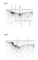
- FIG. 3a diagrammatic visualization of the flow inside a shut-off valve housing according to the present invention.
- FIG. 4a diagrammatic visualization of the flow inside a prior-art shut-off valve housing.
- FIG. 1shows a partially sectioned lateral view of a shut-off valve housing 1 of a shut-off valve, which is configured in the form of a butterfly valve and used as a shut-off valve in water pipes.
- the shut-off valve housing 1comprises a through-channel 5 , which extends inside a main body 2 between in inlet opening 3 and an outlet opening 4 , and a valve seat 6 disposed inside the through-channel 5 .
- the through-channel 5which has a circular cross section, comprises an inflow region 7 disposed upstream of the valve seat 6 and an outflow region 8 immediately downstream of the valve seat 6 on the outflow side.
- the shut-off valve housing 1which is made of cast iron, another metal, or a plastic material, comprises a lateral bearing flange 9 for the rotary support of a flap- or disk-shaped valve body (not shown) and connecting flanges 10 and 11 on both ends for connecting the housing to pipelines.
- a bearing bore 12Disposed in the lateral bearing flange 3 is a bearing bore 12 , which extends at right angles with respect to the longitudinal axis of the main body 2 , for a drive shaft of the valve body, which is capable of being rotated between a closed position and an open position.
- the valve seat 6is a hard-faced valve seat and can be produced with a weld overlay made, e.g., from stainless steel (chromium-nickel alloy).
- the inside wall 13 of the main body 2can have a protuberance 14 projecting inwardly into the through-channel 5 and having a recess 15 in the shape of an annular groove disposed on the inside surface for receiving the material which is applied by means of deposition welding.
- the inflow region 7 of the through-channel 5which, as seen in the direction of flow, is disposed upstream of the valve seat 6 first has a continuously increasing diameter and subsequently, up to the valve seat 6 , a continuously decreasing diameter.
- the through-channel 5has an inflow region 7 with an outwardly curved contour, i.e., curved towards the outside surface of the main body 2 .
- the outflow region 8 of the through-channel 5which is disposed immediately downstream of the valve seat 6 on the outflow side, has a radially inwardly curved contour, i.e., curved towards the central axis of the through-channel 5 .
- the inwardly curved outflow region 8 of the through-channel 5extends at a radius of curvature R 1 , which is preferably selected in such a manner that the product (R 1 ⁇ DN/Di), i.e., the product of this radius R 1 and the discharge coefficient, i.e., the quotient of a nominal diameter DN of the valve housing and an inside diameter Di at the narrowest point of the through-channel 5 , has a value between 150 and 400.
- the curvature in the outflow region 8 of the through-channel 5is designed in such a manner that the transition from the valve seat 6 to the outflow region 8 extends as parallel as possible to the central axis of the through-channel 5 and, thus, as parallel as possible to the direction of flow. This makes it possible to attain a flow path that is as disturbance-free as possible.
- the radius R 2 of the region 13is preferably selected to ensure that the product (R 2 ⁇ DN/Di), i.e., the product of this radius R 2 and the discharge coefficient, i.e., the quotient of the nominal diameter DN of the valve housing 1 and the inside diameter Di at the narrowest point of the through-channel 5 , has a value between 150 and 400.
- the flow visualization of FIG. 4indicates that, along the inside wall 13 of the main body 2 , back flows and turbulences form on the outflow side of the valve seat 6 when the outflow region has an outwardly curved contour, i.e., curved toward the outside surface of the housing 2 .
Landscapes
- Engineering & Computer Science (AREA)
- General Engineering & Computer Science (AREA)
- Mechanical Engineering (AREA)
- Lift Valve (AREA)
- Check Valves (AREA)
Abstract
Description
Claims (20)
Applications Claiming Priority (3)
| Application Number | Priority Date | Filing Date | Title |
|---|---|---|---|
| DE102015118001.4 | 2015-10-22 | ||
| DE102015118001.4ADE102015118001A1 (en) | 2015-10-22 | 2015-10-22 | Absperrarmaturengehäuse |
| DE102015118001 | 2015-10-22 |
Publications (2)
| Publication Number | Publication Date |
|---|---|
| US20170114917A1 US20170114917A1 (en) | 2017-04-27 |
| US10465813B2true US10465813B2 (en) | 2019-11-05 |
Family
ID=58490001
Family Applications (1)
| Application Number | Title | Priority Date | Filing Date |
|---|---|---|---|
| US15/297,273Active2037-03-28US10465813B2 (en) | 2015-10-22 | 2016-10-19 | Housing for a shut-off valve |
Country Status (3)
| Country | Link |
|---|---|
| US (1) | US10465813B2 (en) |
| CN (1) | CN106949282B (en) |
| DE (1) | DE102015118001A1 (en) |
Citations (12)
| Publication number | Priority date | Publication date | Assignee | Title |
|---|---|---|---|---|
| US3420500A (en)* | 1965-12-14 | 1969-01-07 | Dresser Ind | Operating mechanism for butterfly valve |
| US3525499A (en)* | 1967-04-17 | 1970-08-25 | Dresser Ind | Valve seat construction |
| US3905577A (en)* | 1973-03-08 | 1975-09-16 | Anchor Darling Valve Co | Valve |
| US4082246A (en)* | 1976-07-21 | 1978-04-04 | Dresser Industries, Inc. | Butterfly valve thruport seal |
| US4285498A (en) | 1976-05-17 | 1981-08-25 | Imperial Chemical Industries Limited | Control valves |
| US4340549A (en)* | 1981-03-27 | 1982-07-20 | Mckim Robert E | Dual input carburetor |
| US4480815A (en)* | 1982-11-19 | 1984-11-06 | Saab-Scania Aktiebolag | Sealing device for valves |
| EP0124821A1 (en) | 1983-05-09 | 1984-11-14 | Siemens Aktiengesellschaft | Valve having a conical seat |
| FR2606115A1 (en)* | 1986-10-31 | 1988-05-06 | Peugeot | Butterfly valve particularly for a motor vehicle, and its application to a carburetter |
| DE19600567A1 (en)* | 1996-01-09 | 1997-03-27 | Daimler Benz Ag | Exhaust throttle for internal combustion engine |
| EP1757851A2 (en)* | 2005-08-24 | 2007-02-28 | Klaus Beck | Air shutter casing device and mountable sealing compensation element |
| EP2017510A1 (en)* | 2007-06-12 | 2009-01-21 | Arno Hofmann | Gas fed revolving flap valve |
Family Cites Families (7)
| Publication number | Priority date | Publication date | Assignee | Title |
|---|---|---|---|---|
| GB302526A (en)* | 1928-03-08 | 1928-12-20 | Glenfield & Kennedy Ltd | Improvements in pivoted disc valves |
| US2017510A (en)* | 1931-02-04 | 1935-10-15 | Frank T Powers | Powdering machine |
| US2980388A (en)* | 1955-04-15 | 1961-04-18 | Baldwin Lima Hamilton Corp | Butterfly valve |
| CN101305228B (en)* | 2005-11-12 | 2011-05-04 | 图钦哈根有限公司 | Double seat valve |
| DE102011004993A1 (en)* | 2011-03-02 | 2012-09-06 | Robert Bosch Gmbh | Valve device for switching or metering a fluid |
| DE102011120628A1 (en)* | 2011-12-09 | 2013-06-13 | Illinois Tool Works Inc. | check valve |
| CN103423499B (en)* | 2012-05-24 | 2016-06-22 | 上海茂德企业集团有限公司 | A kind of Wedge Gate Valves valve body with weldering replacing valve seat and processing method thereof |
- 2015
- 2015-10-22DEDE102015118001.4Apatent/DE102015118001A1/ennot_activeWithdrawn
- 2016
- 2016-10-19USUS15/297,273patent/US10465813B2/enactiveActive
- 2016-10-20CNCN201610915900.8Apatent/CN106949282B/enactiveActive
Patent Citations (14)
| Publication number | Priority date | Publication date | Assignee | Title |
|---|---|---|---|---|
| US3420500A (en)* | 1965-12-14 | 1969-01-07 | Dresser Ind | Operating mechanism for butterfly valve |
| US3525499A (en)* | 1967-04-17 | 1970-08-25 | Dresser Ind | Valve seat construction |
| US3905577A (en)* | 1973-03-08 | 1975-09-16 | Anchor Darling Valve Co | Valve |
| US4285498A (en) | 1976-05-17 | 1981-08-25 | Imperial Chemical Industries Limited | Control valves |
| DE2722036C2 (en) | 1976-05-17 | 1982-04-08 | Imperial Chemical Industries Ltd., London | Valve stem sealing |
| US4082246A (en)* | 1976-07-21 | 1978-04-04 | Dresser Industries, Inc. | Butterfly valve thruport seal |
| US4340549A (en)* | 1981-03-27 | 1982-07-20 | Mckim Robert E | Dual input carburetor |
| US4480815A (en)* | 1982-11-19 | 1984-11-06 | Saab-Scania Aktiebolag | Sealing device for valves |
| EP0124821A1 (en) | 1983-05-09 | 1984-11-14 | Siemens Aktiengesellschaft | Valve having a conical seat |
| US4607822A (en)* | 1983-05-09 | 1986-08-26 | Kraftwerk Union Aktiengesellschaft | Shutoff valve with a conical valve seat |
| FR2606115A1 (en)* | 1986-10-31 | 1988-05-06 | Peugeot | Butterfly valve particularly for a motor vehicle, and its application to a carburetter |
| DE19600567A1 (en)* | 1996-01-09 | 1997-03-27 | Daimler Benz Ag | Exhaust throttle for internal combustion engine |
| EP1757851A2 (en)* | 2005-08-24 | 2007-02-28 | Klaus Beck | Air shutter casing device and mountable sealing compensation element |
| EP2017510A1 (en)* | 2007-06-12 | 2009-01-21 | Arno Hofmann | Gas fed revolving flap valve |
Non-Patent Citations (1)
| Title |
|---|
| Result of examination report for German Patent Application No. 10 2015 118 001.4 filed Oct. 22, 2015, 1 page. |
Also Published As
| Publication number | Publication date |
|---|---|
| CN106949282A (en) | 2017-07-14 |
| CN106949282B (en) | 2020-03-27 |
| US20170114917A1 (en) | 2017-04-27 |
| DE102015118001A1 (en) | 2017-04-27 |
Similar Documents
| Publication | Publication Date | Title |
|---|---|---|
| US7896312B2 (en) | Ball valve with removable means for retaining the axial seal | |
| JP3708538B1 (en) | Triple eccentric butterfly valve | |
| US8720856B2 (en) | Valve with a two-piece sealing gasket | |
| US20140020774A1 (en) | Check valve having an optimized closing element | |
| US10344873B2 (en) | Control or shutoff valve | |
| JP2018517879A5 (en) | ||
| CN107923542B (en) | Knife switch valve gasket | |
| JP2019086151A (en) | Diaphragm valve with metal valve seat | |
| JP3209608U (en) | Powder transport tube | |
| KR101647100B1 (en) | Screw vane for swirl reduction | |
| US8857791B2 (en) | Balancing valve | |
| US9441740B2 (en) | Cartridge seated plug valve | |
| US10465813B2 (en) | Housing for a shut-off valve | |
| US20190195146A1 (en) | Valve device | |
| JP6811104B2 (en) | Butterfly valve and butterfly valve manufacturing method | |
| US813771A (en) | Wicket-valve. | |
| US9732858B2 (en) | Self-centering metal-to-metal seals for use with valves | |
| US20120313029A1 (en) | Valve for controlling a fluid | |
| KR102151431B1 (en) | Check valve capable of assembling | |
| CN105276236B (en) | Shut-off valve | |
| JP2015224686A (en) | Double eccentric butterfly valve | |
| JP5171920B2 (en) | Butterfly valve | |
| KR200426895Y1 (en) | Triple eccentric butterfly valve with double replaceable seal | |
| BE1024257A1 (en) | CORROSION RESISTANT BALL VALVE | |
| HUE028280T2 (en) | Regulating ball valve |
Legal Events
| Date | Code | Title | Description |
|---|---|---|---|
| AS | Assignment | Owner name:VAG - ARMATUREN GMBH, GERMANY Free format text:ASSIGNMENT OF ASSIGNORS INTEREST;ASSIGNORS:SCHULZ, CARL;HEROLD, HERIBERT;REEL/FRAME:041058/0759 Effective date:20170118 | |
| STPP | Information on status: patent application and granting procedure in general | Free format text:FINAL REJECTION MAILED | |
| STPP | Information on status: patent application and granting procedure in general | Free format text:DOCKETED NEW CASE - READY FOR EXAMINATION | |
| STPP | Information on status: patent application and granting procedure in general | Free format text:NOTICE OF ALLOWANCE MAILED -- APPLICATION RECEIVED IN OFFICE OF PUBLICATIONS | |
| STPP | Information on status: patent application and granting procedure in general | Free format text:PUBLICATIONS -- ISSUE FEE PAYMENT VERIFIED | |
| STCF | Information on status: patent grant | Free format text:PATENTED CASE | |
| AS | Assignment | Owner name:VAG - ARMATUREN GMBH, GERMANY Free format text:CORRECTIVE ASSIGNMENT TO CORRECT THE NAME OF FIRST ASSIGNOR, EXECUTION DATE AND ASSIGNMENT AGREEMENT PREVIOUSLY RECORDED ON REEL 041058 FRAME 0759. ASSIGNOR(S) HEREBY CONFIRMS THE ASSIGNMENT;ASSIGNORS:SCHULTZ, CARL;HEROLD, HERIBERT;SIGNING DATES FROM 20170118 TO 20190619;REEL/FRAME:052092/0161 | |
| MAFP | Maintenance fee payment | Free format text:PAYMENT OF MAINTENANCE FEE, 4TH YEAR, LARGE ENTITY (ORIGINAL EVENT CODE: M1551); ENTITY STATUS OF PATENT OWNER: LARGE ENTITY Year of fee payment:4 |