US10465286B2 - Method and apparatus to help promote contact of gas with vaporized material - Google Patents
Method and apparatus to help promote contact of gas with vaporized materialDownload PDFInfo
- Publication number
- US10465286B2 US10465286B2US15/295,662US201615295662AUS10465286B2US 10465286 B2US10465286 B2US 10465286B2US 201615295662 AUS201615295662 AUS 201615295662AUS 10465286 B2US10465286 B2US 10465286B2
- Authority
- US
- United States
- Prior art keywords
- holder
- gas
- container
- help
- vaporized
- Prior art date
- Legal status (The legal status is an assumption and is not a legal conclusion. Google has not performed a legal analysis and makes no representation as to the accuracy of the status listed.)
- Expired - Lifetime, expires
Links
Images


Classifications
- C—CHEMISTRY; METALLURGY
- C23—COATING METALLIC MATERIAL; COATING MATERIAL WITH METALLIC MATERIAL; CHEMICAL SURFACE TREATMENT; DIFFUSION TREATMENT OF METALLIC MATERIAL; COATING BY VACUUM EVAPORATION, BY SPUTTERING, BY ION IMPLANTATION OR BY CHEMICAL VAPOUR DEPOSITION, IN GENERAL; INHIBITING CORROSION OF METALLIC MATERIAL OR INCRUSTATION IN GENERAL
- C23C—COATING METALLIC MATERIAL; COATING MATERIAL WITH METALLIC MATERIAL; SURFACE TREATMENT OF METALLIC MATERIAL BY DIFFUSION INTO THE SURFACE, BY CHEMICAL CONVERSION OR SUBSTITUTION; COATING BY VACUUM EVAPORATION, BY SPUTTERING, BY ION IMPLANTATION OR BY CHEMICAL VAPOUR DEPOSITION, IN GENERAL
- C23C16/00—Chemical coating by decomposition of gaseous compounds, without leaving reaction products of surface material in the coating, i.e. chemical vapour deposition [CVD] processes
- C23C16/44—Chemical coating by decomposition of gaseous compounds, without leaving reaction products of surface material in the coating, i.e. chemical vapour deposition [CVD] processes characterised by the method of coating
- C23C16/448—Chemical coating by decomposition of gaseous compounds, without leaving reaction products of surface material in the coating, i.e. chemical vapour deposition [CVD] processes characterised by the method of coating characterised by the method used for generating reactive gas streams, e.g. by evaporation or sublimation of precursor materials
- C23C16/4481—Chemical coating by decomposition of gaseous compounds, without leaving reaction products of surface material in the coating, i.e. chemical vapour deposition [CVD] processes characterised by the method of coating characterised by the method used for generating reactive gas streams, e.g. by evaporation or sublimation of precursor materials by evaporation using carrier gas in contact with the source material
- C23C16/4483—Chemical coating by decomposition of gaseous compounds, without leaving reaction products of surface material in the coating, i.e. chemical vapour deposition [CVD] processes characterised by the method of coating characterised by the method used for generating reactive gas streams, e.g. by evaporation or sublimation of precursor materials by evaporation using carrier gas in contact with the source material using a porous body
- C—CHEMISTRY; METALLURGY
- C23—COATING METALLIC MATERIAL; COATING MATERIAL WITH METALLIC MATERIAL; CHEMICAL SURFACE TREATMENT; DIFFUSION TREATMENT OF METALLIC MATERIAL; COATING BY VACUUM EVAPORATION, BY SPUTTERING, BY ION IMPLANTATION OR BY CHEMICAL VAPOUR DEPOSITION, IN GENERAL; INHIBITING CORROSION OF METALLIC MATERIAL OR INCRUSTATION IN GENERAL
- C23C—COATING METALLIC MATERIAL; COATING MATERIAL WITH METALLIC MATERIAL; SURFACE TREATMENT OF METALLIC MATERIAL BY DIFFUSION INTO THE SURFACE, BY CHEMICAL CONVERSION OR SUBSTITUTION; COATING BY VACUUM EVAPORATION, BY SPUTTERING, BY ION IMPLANTATION OR BY CHEMICAL VAPOUR DEPOSITION, IN GENERAL
- C23C16/00—Chemical coating by decomposition of gaseous compounds, without leaving reaction products of surface material in the coating, i.e. chemical vapour deposition [CVD] processes
- C23C16/44—Chemical coating by decomposition of gaseous compounds, without leaving reaction products of surface material in the coating, i.e. chemical vapour deposition [CVD] processes characterised by the method of coating
- C23C16/4401—Means for minimising impurities, e.g. dust, moisture or residual gas, in the reaction chamber
- C23C16/4408—Means for minimising impurities, e.g. dust, moisture or residual gas, in the reaction chamber by purging residual gases from the reaction chamber or gas lines
- C—CHEMISTRY; METALLURGY
- C23—COATING METALLIC MATERIAL; COATING MATERIAL WITH METALLIC MATERIAL; CHEMICAL SURFACE TREATMENT; DIFFUSION TREATMENT OF METALLIC MATERIAL; COATING BY VACUUM EVAPORATION, BY SPUTTERING, BY ION IMPLANTATION OR BY CHEMICAL VAPOUR DEPOSITION, IN GENERAL; INHIBITING CORROSION OF METALLIC MATERIAL OR INCRUSTATION IN GENERAL
- C23C—COATING METALLIC MATERIAL; COATING MATERIAL WITH METALLIC MATERIAL; SURFACE TREATMENT OF METALLIC MATERIAL BY DIFFUSION INTO THE SURFACE, BY CHEMICAL CONVERSION OR SUBSTITUTION; COATING BY VACUUM EVAPORATION, BY SPUTTERING, BY ION IMPLANTATION OR BY CHEMICAL VAPOUR DEPOSITION, IN GENERAL
- C23C16/00—Chemical coating by decomposition of gaseous compounds, without leaving reaction products of surface material in the coating, i.e. chemical vapour deposition [CVD] processes
- C23C16/44—Chemical coating by decomposition of gaseous compounds, without leaving reaction products of surface material in the coating, i.e. chemical vapour deposition [CVD] processes characterised by the method of coating
- C23C16/448—Chemical coating by decomposition of gaseous compounds, without leaving reaction products of surface material in the coating, i.e. chemical vapour deposition [CVD] processes characterised by the method of coating characterised by the method used for generating reactive gas streams, e.g. by evaporation or sublimation of precursor materials
- C23C16/4481—Chemical coating by decomposition of gaseous compounds, without leaving reaction products of surface material in the coating, i.e. chemical vapour deposition [CVD] processes characterised by the method of coating characterised by the method used for generating reactive gas streams, e.g. by evaporation or sublimation of precursor materials by evaporation using carrier gas in contact with the source material
- C—CHEMISTRY; METALLURGY
- C23—COATING METALLIC MATERIAL; COATING MATERIAL WITH METALLIC MATERIAL; CHEMICAL SURFACE TREATMENT; DIFFUSION TREATMENT OF METALLIC MATERIAL; COATING BY VACUUM EVAPORATION, BY SPUTTERING, BY ION IMPLANTATION OR BY CHEMICAL VAPOUR DEPOSITION, IN GENERAL; INHIBITING CORROSION OF METALLIC MATERIAL OR INCRUSTATION IN GENERAL
- C23C—COATING METALLIC MATERIAL; COATING MATERIAL WITH METALLIC MATERIAL; SURFACE TREATMENT OF METALLIC MATERIAL BY DIFFUSION INTO THE SURFACE, BY CHEMICAL CONVERSION OR SUBSTITUTION; COATING BY VACUUM EVAPORATION, BY SPUTTERING, BY ION IMPLANTATION OR BY CHEMICAL VAPOUR DEPOSITION, IN GENERAL
- C23C16/00—Chemical coating by decomposition of gaseous compounds, without leaving reaction products of surface material in the coating, i.e. chemical vapour deposition [CVD] processes
- C23C16/44—Chemical coating by decomposition of gaseous compounds, without leaving reaction products of surface material in the coating, i.e. chemical vapour deposition [CVD] processes characterised by the method of coating
- C23C16/455—Chemical coating by decomposition of gaseous compounds, without leaving reaction products of surface material in the coating, i.e. chemical vapour deposition [CVD] processes characterised by the method of coating characterised by the method used for introducing gases into reaction chamber or for modifying gas flows in reaction chamber
- C23C16/45523—Pulsed gas flow or change of composition over time
- C23C16/45525—Atomic layer deposition [ALD]
- C23C16/45544—Atomic layer deposition [ALD] characterized by the apparatus
- C—CHEMISTRY; METALLURGY
- C23—COATING METALLIC MATERIAL; COATING MATERIAL WITH METALLIC MATERIAL; CHEMICAL SURFACE TREATMENT; DIFFUSION TREATMENT OF METALLIC MATERIAL; COATING BY VACUUM EVAPORATION, BY SPUTTERING, BY ION IMPLANTATION OR BY CHEMICAL VAPOUR DEPOSITION, IN GENERAL; INHIBITING CORROSION OF METALLIC MATERIAL OR INCRUSTATION IN GENERAL
- C23C—COATING METALLIC MATERIAL; COATING MATERIAL WITH METALLIC MATERIAL; SURFACE TREATMENT OF METALLIC MATERIAL BY DIFFUSION INTO THE SURFACE, BY CHEMICAL CONVERSION OR SUBSTITUTION; COATING BY VACUUM EVAPORATION, BY SPUTTERING, BY ION IMPLANTATION OR BY CHEMICAL VAPOUR DEPOSITION, IN GENERAL
- C23C16/00—Chemical coating by decomposition of gaseous compounds, without leaving reaction products of surface material in the coating, i.e. chemical vapour deposition [CVD] processes
- C23C16/44—Chemical coating by decomposition of gaseous compounds, without leaving reaction products of surface material in the coating, i.e. chemical vapour deposition [CVD] processes characterised by the method of coating
- C23C16/50—Chemical coating by decomposition of gaseous compounds, without leaving reaction products of surface material in the coating, i.e. chemical vapour deposition [CVD] processes characterised by the method of coating using electric discharges
- F—MECHANICAL ENGINEERING; LIGHTING; HEATING; WEAPONS; BLASTING
- F17—STORING OR DISTRIBUTING GASES OR LIQUIDS
- F17C—VESSELS FOR CONTAINING OR STORING COMPRESSED, LIQUEFIED OR SOLIDIFIED GASES; FIXED-CAPACITY GAS-HOLDERS; FILLING VESSELS WITH, OR DISCHARGING FROM VESSELS, COMPRESSED, LIQUEFIED, OR SOLIDIFIED GASES
- F17C11/00—Use of gas-solvents or gas-sorbents in vessels
- F—MECHANICAL ENGINEERING; LIGHTING; HEATING; WEAPONS; BLASTING
- F17—STORING OR DISTRIBUTING GASES OR LIQUIDS
- F17C—VESSELS FOR CONTAINING OR STORING COMPRESSED, LIQUEFIED OR SOLIDIFIED GASES; FIXED-CAPACITY GAS-HOLDERS; FILLING VESSELS WITH, OR DISCHARGING FROM VESSELS, COMPRESSED, LIQUEFIED, OR SOLIDIFIED GASES
- F17C3/00—Vessels not under pressure
- F17C3/02—Vessels not under pressure with provision for thermal insulation
- H—ELECTRICITY
- H01—ELECTRIC ELEMENTS
- H01L—SEMICONDUCTOR DEVICES NOT COVERED BY CLASS H10
- H01L21/00—Processes or apparatus adapted for the manufacture or treatment of semiconductor or solid state devices or of parts thereof
- H01L21/67—Apparatus specially adapted for handling semiconductor or electric solid state devices during manufacture or treatment thereof; Apparatus specially adapted for handling wafers during manufacture or treatment of semiconductor or electric solid state devices or components ; Apparatus not specifically provided for elsewhere
- H01L21/67005—Apparatus not specifically provided for elsewhere
- H01L21/67011—Apparatus for manufacture or treatment
- H01L21/67098—Apparatus for thermal treatment
- F—MECHANICAL ENGINEERING; LIGHTING; HEATING; WEAPONS; BLASTING
- F17—STORING OR DISTRIBUTING GASES OR LIQUIDS
- F17C—VESSELS FOR CONTAINING OR STORING COMPRESSED, LIQUEFIED OR SOLIDIFIED GASES; FIXED-CAPACITY GAS-HOLDERS; FILLING VESSELS WITH, OR DISCHARGING FROM VESSELS, COMPRESSED, LIQUEFIED, OR SOLIDIFIED GASES
- F17C2203/00—Vessel construction, in particular walls or details thereof
- F17C2203/03—Thermal insulations
- Y—GENERAL TAGGING OF NEW TECHNOLOGICAL DEVELOPMENTS; GENERAL TAGGING OF CROSS-SECTIONAL TECHNOLOGIES SPANNING OVER SEVERAL SECTIONS OF THE IPC; TECHNICAL SUBJECTS COVERED BY FORMER USPC CROSS-REFERENCE ART COLLECTIONS [XRACs] AND DIGESTS
- Y02—TECHNOLOGIES OR APPLICATIONS FOR MITIGATION OR ADAPTATION AGAINST CLIMATE CHANGE
- Y02E—REDUCTION OF GREENHOUSE GAS [GHG] EMISSIONS, RELATED TO ENERGY GENERATION, TRANSMISSION OR DISTRIBUTION
- Y02E60/00—Enabling technologies; Technologies with a potential or indirect contribution to GHG emissions mitigation
- Y02E60/30—Hydrogen technology
- Y02E60/32—Hydrogen storage
- Y02E60/321—
- Y—GENERAL TAGGING OF NEW TECHNOLOGICAL DEVELOPMENTS; GENERAL TAGGING OF CROSS-SECTIONAL TECHNOLOGIES SPANNING OVER SEVERAL SECTIONS OF THE IPC; TECHNICAL SUBJECTS COVERED BY FORMER USPC CROSS-REFERENCE ART COLLECTIONS [XRACs] AND DIGESTS
- Y10—TECHNICAL SUBJECTS COVERED BY FORMER USPC
- Y10S—TECHNICAL SUBJECTS COVERED BY FORMER USPC CROSS-REFERENCE ART COLLECTIONS [XRACs] AND DIGESTS
- Y10S261/00—Gas and liquid contact apparatus
- Y10S261/65—Vaporizers
Definitions
- One or more embodiments described in this patent applicationrelate to the field of vaporizers.
- a vaporizermay be used, for example, to deliver material in a carrier gas to a process chamber of semiconductor processing equipment such as, for example, chemical vapor deposition (CVD) equipment to form a film over a workpiece or an ion implanter to accelerate ions toward a workpiece for injection into the workpiece.
- CVDchemical vapor deposition
- One vaporizer called a bubblerdelivers vapor from material in a liquid state to a process chamber by heating the liquid material in a container and introducing a carrier gas at a controlled rate into the liquid material near the bottom of the container.
- the carrier gasthen becomes saturated with vapor from the liquid material as the carrier gas bubbles to the top of the container.
- the saturated carrier gasis then transported to the process chamber.
- Vapor from material in a solid statemay be delivered to a process chamber by heating the material to its sublimation temperature and directing the flow of a carrier gas past the heated material.
- the inventionrelates to a method utilizing a vaporizer including at least one wall defining an internal compartment, the method comprising: dissolving a solid source material in a solvent; and removing said solvent to yield a metal complex, wherein the metal complex is disposed within the internal compartment of the vaporizer.
- the inventionin another aspect, relates to a method utilizing a plurality of containers, wherein each container of the plurality of containers defines a cavity therein, the method including: introducing source material comprising a solid into the cavity of each container of the plurality of containers; dissolving at least a portion of the source material in a solvent; removing said solvent from said source material; and stacking said plurality of containers in a vaporizer ampoule.
- the inventionin another aspect, relates to a vapor delivery system including: a plurality of containers, wherein each container of the plurality of containers defines therein a cavity, and the cavity of each container contains a solid source material and a solvent; and a vaporizer ampoule adapted to receive said plurality of containers.
- the inventionin another aspect, relates to a vaporizer including: at least one wall defining an internal compartment; and a solid source material disposed within the internal compartment, the solid source material comprising a metal complex processed by dissolution in a solvent followed by removal of the solvent under reduced pressure.
- the inventionin another aspect, relates to a vaporizer comprising a vessel having (i) a thermally conductive vessel wall enclosing an interior volume, (ii) a gas inlet adapted to supply gas to the interior volume, (iii) a gas outlet adapted to receive gas carrying vaporized material from the interior volume, and (iv) a plurality of solid material holders disposed at different levels within the vessel, wherein each solid material holder has a solid material support surface and a thermally conductive holder sidewall adapted to be in substantial thermal contact with the vessel wall at a vessel operating temperature, and is adapted to hold a solid vaporizable material having a solid form comprising any of particles, agglomerated particles, powders, crystalline material, loose material, and discontinuous material, and wherein the vessel is adapted to transfer heat through the vessel wall to the thermally conductive holder sidewall.
- the inventionin another aspect, relates to a method utilizing vaporizer apparatus comprising a vessel having (i) a thermally conductive vessel wall enclosing an interior volume, (ii) a gas inlet adapted to supply gas to the interior volume, (iii) a gas outlet adapted to receive gas carrying vaporized material from the interior volume, and (iv) a plurality of solid material holders disposed at different levels within the vessel, wherein each solid material holder has a solid material support surface and a thermally conductive holder sidewall in contact with the vessel wall, and contains a solid vaporizable material having a solid form comprising any of particles, agglomerated particles, powders, crystalline material, loose material, and discontinuous material, the method comprising: (a) heating the vessel to vaporize at least a portion of the vaporizable material; (b) introducing a first gas to the vessel via the gas inlet to contact the vaporizable material and produce a second gas comprising vaporized material; and
- the inventionrelates to a vapor delivery vessel for vaporizing and delivering vaporized source material, the vessel comprising: a peripheral vessel wall bounding an interior volume; a gas inlet and a gas outlet arranged in at least intermittent fluid communication with the interior volume, the gas inlet being adapted to supply a first gas to the interior volume; and at least one support surface disposed within the interior volume and adapted to support vaporizable source material in or along a flow path of said first gas within the interior volume; characterized by at least one of the following: (a) the vessel wall is formed of any of a polymeric material, a ceramic material, a composite material, layered materials, and lined materials; (b) the support surface is defined by a support structure disposed within the interior volume, wherein the support structure and the peripheral vessel wall are formed of materials having different coefficients of thermal expansion, and are sized and shaped to be in substantial thermal contact with one another at a vessel operating temperature; (c) the interior volume includes at least one gas-permeable bag supported by
- At least one disclosed apparatuscomprises a container and structure to help support material in the container with an increased exposed surface area to help promote contact of a gas with vaporized material.
- the structure for at least one disclosed apparatusmay help support material for vaporization in the same form as when the material is placed at the structure.
- At least one disclosed apparatuscomprises a container and structure to help support material in the container with an increased exposed surface area to help promote contact of a gas with vaporized material for delivery to atomic layer deposition (ALD) process equipment.
- ALDatomic layer deposition
- At least one disclosed apparatuscomprises a container and structure to help support liquid material in the container with an increased exposed surface area to help promote contact of a gas with vaporized liquid material.
- At least one disclosed apparatuscomprises a container and one or more holders that define a support surface to help support material in the container with an increased exposed surface area to help promote contact of a gas with vaporized material.
- a holder for at least one disclosed apparatusmay have one or more sidewalls along at least a portion of a perimeter of an opening through the support surface of the holder to help define a passageway through which gas may flow through the holder.
- At least one disclosed apparatuscomprises a container and one or more holders that define a support surface to help support material in the container with an increased exposed surface area to help promote contact of a gas with vaporized material.
- a holder for at least one disclosed apparatusmay have one or more walls and one or more passageways within one or more walls to allow gas to flow through the holder.
- At least one disclosed apparatuscomprises a container and one or more holders that define a support surface to help support material in the container with an increased exposed surface area to help promote contact of a gas with vaporized material.
- a holder for at least one disclosed apparatusmay define a support surface at least a portion of which is over at least partially permeable material through which gas may flow.
- At least one disclosed methodcomprises heating a container to help vaporize material in the container, introducing gas into the container, and delivering gas resulting from contact of introduced gas with vaporized material to process equipment.
- the container for at least one disclosed methodmay have structure to help support material in the container with an increased exposed surface area to help promote contact of a gas with vaporized material.
- the structure for at least one disclosed methodmay help support material for vaporization in the same form as when the material is placed at the structure.
- At least one disclosed methodcomprises heating a container to help vaporize material in the container, introducing gas into the container, delivering gas resulting from contact of introduced gas with vaporized material to atomic layer deposition process equipment, and performing an atomic layer deposition process using the delivered gas.
- the container for at least one disclosed methodmay have structure to help support material in the container with an increased exposed surface area to help promote contact of a gas with vaporized material.
- FIG. 1illustrates, for one or more embodiments, a system using a vaporizer that helps promote contact of a gas with vaporized material
- FIG. 2illustrates, for one or more embodiments, a flow diagram for gas delivery in the system of FIG. 1 ;
- FIG. 3illustrates, for one example embodiment, a perspective, broken view of a vaporizer container having holders to help promote contact of a gas with vapor from material supported by the holders;
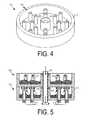
- FIG. 4illustrates, for one example embodiment, a perspective view of a holder
- FIG. 5illustrates, for one example embodiment, a cross-sectional view of a holder positioned over another holder
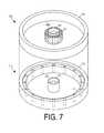
- FIG. 6illustrates, for another example embodiment, a perspective, exploded view of a holder positioned over another holder
- FIG. 7illustrates, for another example embodiment, a perspective, exploded view of a holder positioned over another holder
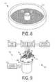
- FIG. 8illustrates, for another example embodiment, a perspective view of a holder
- FIG. 9illustrates, for one or more embodiments, a system using the vaporizer container of FIG. 3 .
- FIG. 1illustrates, for one or more embodiments, a system 100 that delivers a desired gas from a vaporizer 110 to process equipment 120 coupled to vaporizer 110 .
- Vaporizer 110vaporizes material, receives a gas from a gas source 130 coupled to vaporizer 110 , and helps deliver to process equipment 120 gas resulting from contact of the received gas with vaporized material.
- Vaporizer 110supports material to be vaporized to help increase exposed surface area of material to be vaporized to help promote contact of the received gas with vaporized material.
- vaporizer 110for one or more embodiments may be used to help deliver the resulting gas to process equipment 120 at relatively higher flow rates.
- Vaporizer 110 for one or more embodimentsmay be used to deliver a desired gas to process equipment 120 in accordance with a flow diagram 200 of FIG. 2 .
- material to be vaporizedis supported in a container of vaporizer 110 to help increase exposed surface area of material to be vaporized.
- Vaporizer 110may be used to vaporize any suitable material in any suitable one or more states and/or in any suitable one or more forms.
- the material to be vaporized for one or more embodimentsmay depend at least in part, for example, on the process or operation to be performed by process equipment 120 .
- Vaporizer 110 for one or more embodimentsmay be used to vaporize any suitable material in a solid state.
- Vaporizer 110 for one or more embodimentsmay be used to vaporize, for example, any suitable solid material characterized by a sublimation temperature in the range of, for example, approximately 20 degrees Celsius to approximately 300 degrees Celsius and a vapor pressure in the range of, for example, approximately 10-2 Torr to approximately 103 Torr.
- Vaporizer 110may be used to vaporize, for example, any suitable material comprising boron (B), phosphorous (P), copper (Cu), gallium (Ga), arsenic (As), ruthenium (Ru), indium (In), antimony (Sb), lanthanum (La), tantalum (Ta), iridium (Ir), decaborane (B 10 H 14 ), hafnium tetrachloride (HfCl 4 ), zirconium tetrachloride (ZrCl 4 ), indium trichloride (InCl 3 ), a metal organic ⁇ -diketonate complex, cyclopentadienyl cycloheptatrienyl titanium (CpTiChT), aluminum trichloride (AlCl 3 ), titanium iodide (Ti x I y ), cyclooctatetraene cyclopentadienyl titanium ((Cot)(Cp)
- Vaporizer 110may be used to vaporize any suitable solid material in any suitable form such as, for example, a powder, agglomerated particles, one or more crystalline bodies, and/or a film.
- a crystalline bodymay have any suitable size and shape, such as a tablet, brick, or puck shape for example.
- Vaporizer 110 for one or more embodimentsmay be used to vaporize any suitable material in a liquid state.
- Vaporizer 110may be used to vaporize, for example, any suitable material comprising tertiaryamylimidotris(dimethylamido)tantalum (Taimata), tetrakis-(diethylamido)titanium (TDEAT), tetrakis-(dimethylamido)titanium (TDMAT), pentakis dimethyl-amidotantalum (PDMAT), tantalum pentaethoxide (TAETO), and bis(ethylcyclopentadienyl)ruthenium (II) (Ru(EtCp) 2 ).
- Vaporizer 110 for one or more embodimentsmay be used to heat any suitable material in a solid state to a liquid state prior to vaporizing the material.
- Vaporizer 110 for or more embodimentsmay be used to vaporize any suitable material having two or more distinct substances in any suitable state and/or form.
- Vaporizer 110may comprise any suitable structure to help support material to be vaporized in any suitable container in any suitable manner to help increase exposed surface area of the material.
- the structuremay be defined, positioned, and/or coupled in any suitable container in any suitable manner.
- the structure for one or more embodimentsmay help support material in the container to help increase exposed surface area of the material relative to a maximum exposed surface area the material could have at rest in the container absent the structure.
- the structure for one or more embodimentsmay help support any suitable material for vaporization in the same form as when the material is placed at the structure.
- material to be vaporized for one or more embodimentsmay be manually or automatically placed at the structure and vaporized without further preparation or conditioning of such material.
- any suitable liquid materialmay be placed at the structure and vaporized while still in liquid form.
- any suitable solid material in any suitable formsuch as a powder, agglomerated particles, and/or one or more crystalline bodies for example, may be placed at the structure and vaporized while still in that same form.
- the structure for one or more embodimentsmay define in any suitable manner one or more material support surfaces to help support material in the container with an increased exposed surface area.
- the structure for one or more embodimentsmay define in any suitable manner one or more material support surfaces in an interior region of the container in addition to a bottom surface of the interior region of the container.
- the structure for one or more embodimentsmay define in an interior region of the container one or more material support surfaces having a total surface area greater than a surface area of a bottom surface of the interior region of the container.
- the structure for one or more embodimentsmay define a plurality of material support surfaces at different levels in the container.
- the structure for one or more embodimentsmay define one or more material support surfaces that span different levels in the container.
- the structure for one or more embodimentsmay define one or more material support surfaces of any suitable shape or contour.
- the structure for one or more embodimentsmay define one or more generally planar material support surfaces.
- the structure for one or more embodimentsmay comprise an integral body to define one or more material support surfaces.
- the structure for one or more embodimentsmay comprise a plurality of bodies to define one or more material support surfaces.
- the structuremay help support and optionally help contain such material over one or more material support surfaces in any suitable manner.
- the materialmay be formed in any suitable manner over one or more material support surfaces.
- the structure for one or more embodimentsmay optionally help support different substances of the material over different material support surfaces.
- the structure for one or more embodimentsmay help support any suitable material over one or more material support surfaces for vaporization in the same form as when the material is placed over such material support surface(s).
- material to be vaporized for one or more embodimentsmay be manually or automatically placed over one or more material support surfaces and vaporized without further preparation or conditioning of such material.
- any suitable liquid materialmay be placed over one or more material support surfaces and vaporized while still in liquid form.
- any suitable solid material in any suitable formsuch as a powder, agglomerated particles, and/or one or more crystalline bodies for example, may be placed over one or more material support surfaces and vaporized while still in that same form.
- the structure for one or more embodimentsmay define in any suitable manner at least a portion of a material support surface over any suitable at least partially permeable material to help support material to be vaporized while allowing a suitable gas to flow through the material support surface.
- vaporizer 110may help increase exposed surface area of the material to be vaporized.
- the structure for one or more embodimentsmay define in any suitable manner one or more passages that turn, curve, and/or wind in any suitable manner in the container. Such structure may then help support material to be vaporized in one or more passages to help increase exposed surface area of the material.
- the structuremay define one or more passages of any suitable size and shape.
- the structure for one or more embodimentsmay comprise a tube to define a passage.
- the structure for one or more embodimentsmay comprise a series of coupled tubes to define a passage.
- the structure for one or more embodimentsmay comprise an integral body defining one or more passages.
- the structure for one or more embodimentsmay comprise a plurality of bodies coupled to define one or more passages.
- the material to be vaporizedis in a liquid state or in a solid state in the form of, for example, a powder, agglomerated particles, and/or one or more crystalline bodies
- the materialmay be poured to fill a portion of one or more passages.
- the materialmay be formed in any suitable manner to any suitable thickness along at least a portion of an inner wall or walls of one or more passages.
- the structure for one or more embodimentsmay optionally help support different substances of the material in different passages.
- the structure for one or more embodimentsmay define in any suitable manner a mesh of any suitable material to help support material to be vaporized to help increase exposed surface area of the material.
- such structuremay comprise steel wool of any suitable density.
- material to be vaporizedis in a solid state in the form of, for example, a powder, agglomerated particles, and/or one or more crystalline bodies, the material may be poured into the mesh structure.
- the structure for one or more embodimentsmay have one or more porous bodies to help support material to be vaporized to help increase exposed surface area of the material.
- a porous body or bodiesmay be of any suitable size and shape and may be formed using any suitable material, such as a porous stainless steel of any suitable density for example.
- Such a porous body or bodies for one or more embodimentsmay be charged with material to be vaporized in any suitable manner and/or may help support material to be vaporized over one or more surfaces of the porous body or bodies.
- a porous body for one embodimentmay have pores of a larger size toward, at, or near a first end of the porous body and pores of a smaller size toward, at, or near an opposite second end of the porous body to help prevent material in the porous body from exiting the porous body prior to being vaporized as gas flows into the first end of the porous body and through the porous body to exit from the second end of the porous body.
- such porous bodiesmay be defined, positioned, and/or coupled in a container in any suitable manner.
- a plurality of porous bodies for one or more embodimentsmay be defined, positioned, and/or coupled in a stack in a container. A porous body in such a stack may or may not be spaced from any subjacent or any superjacent porous body in the stack.
- the structure for one or more embodimentsmay be defined in any suitable manner to help support one or more bags of material to be vaporized with at least a portion of a bag formed from any suitable at least partially permeable material, such as a suitable membrane material for example, to help support material to be vaporized in the bag while allowing a suitable gas to flow into the bag and/or vapor from material in the bag to flow out of the bag.
- the structure for one or more embodimentsmay support one or more such bags to expose surface area of the bag(s) in any suitable manner to help increase exposed surface area of material to be vaporized.
- the structuremay help support a bag to expose opposite sides of the bag to expose surface area of material to be vaporized at both opposite sides of the bag.
- one or more bags of material to be vaporizedmay be placed in and/or on the structure in any suitable manner.
- the structure for one or more embodimentsmay optionally help support different substances of the material in different bags.
- material in the containeris heated to vaporize the material.
- the materialmay be heated in any suitable manner to any suitable temperature using any suitable heating equipment to help transform the material into a gas or vapor state.
- the container for one or more embodimentsmay define and/or have any suitable structure to help increase heated surface area in the container to help increase the rate of vaporization of material in the container.
- the container for one or more embodimentsmay define and/or have any suitable structure to help increase heated surface area in the container relative to a maximum heated surface area the container could have absent such structure.
- the structure to help support material to be vaporized to help increase exposed surface area of the materialmay be defined to help conduct heat and therefore help increase heated surface area in the container.
- a gasis introduced into the container of vaporizer 110 to contact vaporized material.
- Vaporizer 110may be coupled to any suitable gas source 130 in any suitable manner to receive any suitable gas in the container in any suitable manner. Because vaporizer 110 supports material in the container with an increased exposed surface area, vaporizer 110 helps provide a larger interface area at which vaporized material may interact with gas in the container and therefore helps promote contact of introduced gas with vaporized material.
- Vaporizer 110 for one or more embodimentsmay receive any suitable carrier gas to help deliver any suitable vaporized material to process equipment 120 . By helping to promote contact of carrier gas with vaporized material, vaporizer 110 may then help promote saturation of carrier gas with vaporized material.
- Vaporizer 110 for one or more embodimentsmay receive any suitable gas that is reactive with any suitable vaporized material to deliver any suitable resulting gas to process equipment 120 . By helping to promote contact of introduced gas with vaporized material, vaporizer 110 may then help promote chemical reaction of introduced gas with vaporized material.
- the gas to be received by vaporizer 110may depend at least in part, for example, on the material to be vaporized and/or on the process or operation to be performed by process equipment 120 .
- vaporizer 110may receive a carrier gas comprising, for example, hydrogen (H), helium (He), nitrogen (N), oxygen (O), argon (Ar), carbon monoxide (CO), and/or carbon dioxide (CO 2 ).
- vaporizer 110may receive a gas comprising, for example, carbon monoxide (CO), nitrosyl, and/or nitric oxide (NO).
- Vaporizer 110 for one or more embodimentsmay receive a mixture of a gas reactive with vaporized material and any suitable inert gas, such as nitrogen (N) or helium (He) for example.
- vaporizer 110may optionally direct gas flow over and/or through material being vaporized to help increase contact time of introduced gas with material being vaporized. Vaporizer 110 for one or more embodiments may then help promote contact of introduced gas with vaporized material despite any variations in the vaporization rate of the material and/or any variations in the concentration of the vaporized material in the container. Vaporizer 110 may comprise any suitable structure to help direct gas flow over and/or through material being vaporized in any suitable manner.
- vaporizer 110may comprise structure to define one or more passageways through one or more material support surfaces to help direct gas flow over material being vaporized.
- Such passageway(s)may be defined, for example, to help direct gas flow directly over material being vaporized and/or toward any suitable structure to help direct gas flow to circulate or whirl over material being vaporized.
- Vaporizer 110for one or more embodiments may comprise any suitable baffle or diffuser structure to help direct gas flow directly over material being vaporized and/or to help direct gas flow to circulate or whirl over material being vaporized.
- the structure to help support material to be vaporizedmay also serve to help direct gas flow over and/or through material being vaporized.
- gas flowmay be directed through the at least partially permeable material to flow through material being vaporized.
- vaporizer 110comprises structure to help support material to be vaporized in one or more passages that turn, curve, and/or wind in the container, gas flow may be directed through the defined passage(s) to flow over material being vaporized.
- vaporizer 110comprises structure to define a mesh to help support material to be vaporized
- gas flowmay be directed through the mesh to flow over material being vaporized.
- vaporizer 110comprises structure having one or more porous bodies to help support material to be vaporized
- gas flowmay be directed through one or more porous bodies to flow over material being vaporized in one or more porous bodies and/or to flow through material being vaporized over one or more surfaces of one or more porous bodies.
- gas resulting from contact of introduced gas with vaporized materialis delivered to process equipment 120 .
- Vaporizer 110may be coupled to any suitable process equipment 120 in any suitable manner to deliver the resulting gas to process equipment 120 . Because vaporizer 110 helps promote contact of introduced gas with vaporized material, gas for one or more embodiments may be introduced into the container of vaporizer 110 at a relatively higher flow rate to help deliver the resulting gas at a relatively higher flow rate to process equipment 120 .
- Vaporizer 110 for one or more embodimentsmay be used to deliver any suitable gas for use in any suitable semiconductor process to be performed by any suitable process equipment 120 in response to receiving the delivered gas.
- Vaporizer 110 for one or more embodimentsmay be used to deliver any suitable gas for use in any suitable chemical vapor deposition (CVD) process such as, for example, an atomic layer deposition (ALD) process, a plasma enhanced atomic layer deposition (PEALD) process, a metal organic chemical vapor deposition (MOCVD) process, or a plasma enhanced chemical vapor deposition (PECVD) process.
- CVDchemical vapor deposition
- ALDatomic layer deposition
- PEALDplasma enhanced atomic layer deposition
- MOCVDmetal organic chemical vapor deposition
- PECVDplasma enhanced chemical vapor deposition
- vaporizer 110for one or more embodiments may continue to produce gas to be delivered to process equipment 120 while process equipment 120 is not drawing any gas from vaporizer 110 between such bursts. Because vaporizer 110 supports material to be vaporized to help increase exposed surface area of material to be vaporized to help promote contact of received gas with vaporized material, vaporizer 110 for one or more embodiments may produce gas and deliver gas to process equipment 120 with reduced or minimized concern for providing a sufficient flow rate of delivered gas when drawn by process equipment 120 .
- ALDatomic layer deposition
- Vaporizer 110 for one or more embodimentsmay be used to deliver any suitable gas for use in any suitable ion implantation process.
- Operations for blocks 202 , 204 , 206 , 208 , and/or 210may be performed in any suitable order and may or may not be performed so as to overlap in time the performance of any suitable operation with any other suitable operation.
- material in the containermay be heated for block 204 as gas is introduced into the container for block 206 .
- vaporizer 110may be used to deliver any suitable gas to any suitable equipment for any suitable purpose.
- directional termssuch as, for example, top, bottom, up, and down are used for convenience to describe vaporizer 110 relative to one frame of reference regardless of how vaporizer 110 or any component of vaporizer 110 may be oriented in space.
- Vaporizer 110 for one or more embodimentsmay comprise a container having one or more holders defining one or more support surfaces to help support material to help increase exposed surface area of material.
- FIG. 3illustrates, for one example embodiment, a container 300 having a plurality of holders 310 , 320 , 330 , 340 , 350 , and 360 defining respective support surfaces 311 , 321 , 331 , 341 , 351 , and 361 .
- the containermay define in any suitable manner any suitable one or more interior regions in which one or more holders may be defined, positioned, and/or coupled in any suitable manner.
- the containermay define one or more interior regions of any suitable size and shape.
- the container for one embodimentmay have one or more sidewalls, a bottom wall, and/or a top wall to help define an interior region of any suitable size and shape.
- the container for one or more embodimentsmay define in any suitable manner any suitable one or more openings through which material to be vaporized may be placed over, on, and/or in one or more holders in an interior region and/or through which one or more holders may be inserted into an interior region.
- the containermay define one or more openings of any suitable size and shape and in any suitable location relative to one or more interior regions.
- the container for one embodimentmay have a bottom wall and one or more sidewalls to help define an interior region of any suitable size and shape with an opening of any suitable size and shape at or near the top of the container generally opposite the bottom wall.
- container 300may have a bottom wall having a surface 301 and a sidewall 302 to help define a generally cylindrical interior region in container 300 with a generally circular opening at or near the top of container 300 .
- the inner diameter of the generally cylindrical interior region for one or more embodimentsmay be in the range of, for example, approximately 3 inches to approximately 6 inches and for one embodiment may be, for example, approximately 3.75 inches.
- the container for one embodimentmay have a bottom wall and four sidewalls to help define a generally parallelepiped-shaped interior region in the container with a generally rectangular opening at or near the top of the container generally opposite the bottom wall.
- the container for one embodimentmay have a top wall, one or more sidewalls, and a bottom wall to help define an interior region of any suitable size and shape with an opening of any suitable size and shape on a side of the container.
- the container for one embodimentmay have a top wall, three sidewalls, and a bottom wall to help define a generally parallelepiped-shaped interior region in the container with a generally rectangular opening at a fourth side of the container.
- the container for one or more embodimentsmay define one or more interior regions of any suitable size and shape to help heat material in such interior region(s).
- the container for one or more embodimentsmay define an elongated interior region to help support material in the container in proximity to a sidewall.
- the containermay be formed in any suitable manner using any suitable material.
- the container for one embodimentmay be formed using any suitable material that helps conduct heat to help heat and therefore help vaporize material in the container.
- suitable materials for the containermay include, without limitation, stainless steel, aluminum, aluminum alloys, copper, copper alloys, silver, silver alloys, lead, nickel clad, graphite, ceramic material, Hastelloy, Inconel, Monel, and/or one or more polymers.
- the container for one or more embodimentsmay be formed using a composite of materials, layered materials, and/or lined materials.
- container 300is illustrated in the example embodiment of FIG. 3 as having an integral body, the container for another embodiment may be formed from separate pieces.
- the container for one or more embodimentsmay be of a suitable conventional ampoule used for vaporizing material for delivery to processing equipment.
- Any suitable number of one or more holdersmay be defined, positioned, and/or coupled in any suitable container in any suitable manner to help increase exposed surface area of material. Any suitable number of one or more holders may be used for one or more embodiments to help support material in an interior region of a container with an increased exposed surface area relative to a maximum exposed surface area the same total amount of material could have at rest on a bottom surface of the interior region of the container absent any holders in the interior region.
- material to be vaporizedmay optionally be supported on a bottom surface of an interior region of a container in addition to being supported by one or more holders in the interior region. Any suitable number of two or more holders may be used for one or more embodiments to help support material in an interior region of a container such that the total surface area of the surfaces defined by such holders to help support material is greater than the surface area of a bottom surface of the interior region.
- One or more holders for one embodimentmay be defined, positioned, and/or coupled to help support material to be vaporized at different levels in a container.
- One or more holders for one embodimentmay be defined, positioned, and/or coupled to define one or more support surfaces over a bottom surface in an interior region of a container.
- a plurality of holders for one embodimentmay be defined, positioned, and/or coupled to define a plurality of support surfaces at different levels in a container.
- holder 310may be positioned over bottom surface 301 to define support surface 311 over bottom surface 301
- holder 320may be positioned over holder 310 to define support surface 321 over support surface 311
- holder 330may be positioned over holder 320 to define support surface 331 over support surface 321
- holder 340may be positioned over holder 330 to define support surface 341 over support surface 331
- holder 350may be positioned over holder 340 to define support surface 351 over support surface 341
- holder 360may be positioned over holder 350 to define support surface 361 over support surface 351 .
- any suitable number of one or more holderssuch as three, four, or five for example, may be used for one or more other embodiments.
- any suitable amount of any suitable material in any suitable one or more states and/or formmay be placed or formed over, on, and/or in one or more holders in any suitable manner.
- the materialmay comprise, for example, a solid and/or a liquid. Where the material to be vaporized comprises a solid, such material may be in any suitable form such as, for example, a powder, agglomerated particles, one or more crystalline bodies, and/or a film. Material to be vaporized for one embodiment may be manually placed or formed over, on, and/or in one or more holders in any suitable manner. Material to be vaporized for one embodiment may be automatically placed or formed over, on, and/or in one or more holders in any suitable manner using any suitable equipment.
- Material to be vaporized for one embodimentmay be placed over, on, and/or in one or more holders while contained in one or more bags with at least a portion of a bag formed from any suitable at least partially permeable material, such as a suitable membrane material for example, to help support material to be vaporized in the bag while allowing a suitable gas to flow into the bag and/or vapor from material in the bag to flow out of the bag.
- Material to be vaporized for one embodimentmay be placed over, on, and/or in one or more holders while contained in one or more bags with at least a portion of a bag formed from any suitable material that will at least partially disintegrate when heated.
- One or more holders for one embodimentmay be at least partially coated with material to be vaporized in any suitable manner to form a film over one or more support surfaces.
- a suitable materialsuch as a metal complex for example
- a suitable materialsuch as a metal complex for example
- a suitable materialsuch as a metal complex for example, may be dissolved in a solvent and applied over one or more support surfaces followed by removal of the solvent.
- Material to be vaporized for one embodimentmay also optionally be placed or formed over a bottom surface of an interior region of a container.
- One or more holders for one or more embodimentsmay be separable from one or more other holders and removable from a container to help facilitate cleaning and/or refilling such holder(s).
- One or more such holdersmay be placed in a container in any suitable manner.
- One or more holders for one embodimentmay be manually placed in a container.
- One or more holders for one embodimentmay be automatically placed in a container in any suitable manner using any suitable equipment. The placement or formation of material over a support surface of a removable holder may be performed prior to, while, or after the holder is placed in the container.
- a plurality of removable holders for one embodimentmay optionally be placed in a stack in an interior region of a container.
- a plurality of separable and removable holders for one embodimentmay be placed in a container one at a time. After a first holder has been placed in a container, a second holder for one embodiment may be placed in the container to rest on the first holder and any subsequent holder may then be placed in the container to rest on the top holder in the container.
- One or more holders for one embodimentmay be placed in a container to rest directly on another holder.
- One or more holders for one embodimentmay be placed in a container to rest indirectly on another holder where, for example, a gasket or any other suitable structure is placed over the other holder.
- One or more holders for one embodimentmay be placed in a container defining and/or having structure to help support one or more holders in the container.
- Such structuremay be integral with and/or separate from the container.
- one or more inner walls of a containermay be shaped with one or more ledges to help support one or more holders.
- a plurality of removable holders for one embodimentmay be placed in a container together in any suitable manner.
- a plurality of holders for one embodimentmay be coupled to one another in any suitable manner prior to placement of the holders in a container.
- Material to be vaporized for one embodimentmay be placed over one or more support surfaces of one or more removable holders while in a dry box or glove box, for example, and the holder(s) may be placed in a container while in the dry box or glove box to help reduce, minimize, or avoid reaction of the material with, for example, oxygen and/or moisture.
- a holdermay define one or more support surfaces with any suitable size, contour, and shape.
- a holder for one or more embodimentsmay optionally have one or more sidewalls and/or one or more supports of any suitable size and shape relative to a support surface to help support one or more other holders, for example, positioned over the holder and to help define a region through which gas may flow over material supported by the holder.
- a holder for one embodimentmay have one or more sidewalls along at least a portion of the perimeter of a support surface. Such sidewall(s) for one embodiment may be defined to help contain any suitable amount of material supported by the holder. Such sidewall(s) for one embodiment may optionally be grooved along the top to help position a gasket between the holder and a superjacent holder, for example.
- holder 310may define a generally planar support surface 311 generally circular in shape and may have a generally cylindrical sidewall 312 along the perimeter of support surface 311 .
- a holdermay be formed in any suitable manner using any suitable material.
- a holder for one embodimentmay be formed using any suitable material that helps conduct heat to help heat and therefore help vaporize material supported by the holder.
- suitable materials for a holdermay include, without limitation, stainless steel, aluminum, aluminum alloys, copper, copper alloys, silver, silver alloys, lead, nickel clad, graphite, ceramic material, Hastelloy, Inconel, Monel, and/or one or more polymers.
- a holder for one or more embodimentsmay be formed using a composite of materials, layered materials, and/or lined materials. The material(s) used to form a holder may or may not be the same as the material(s) used to form any container in which the holder may be positioned.
- holder 310is illustrated in the example embodiment of FIGS. 3 and 4 as having an integral body defining support surface 311 and sidewall 312 , one or more holders for another embodiment may be formed from separate pieces to define one or more support surfaces and/or one or more sidewalls and/or one or more supports.
- two or more holders in a containermay be similarly formed to help support material to be vaporized in the container.
- the container and one or more holders for one or more embodimentsmay be designed to help promote heat transfer from the container to one or more holders in any suitable manner.
- the container and one or more holders for one or more embodimentsmay be designed to help promote heat transfer from one or more sidewalls of the container to one or more holders through one or more sidewalls of such holder(s).
- container 300may have sidewall 302 to help define a generally cylindrical interior region
- holder 310for example, may have a generally cylindrical sidewall 312 the outer surface of which may be used to help provide thermal contact with the inner surface of sidewall 302 when holder 310 is positioned in container 300 .
- the container and one or more holders for one embodimentmay optionally be manufactured to allow a clearance between the inner surface of one or more sidewalls of the container and the outer surface of one or more sidewalls of a holder to be in a predetermined range, such as in the range of approximately 1/1000th of an inch to approximately 3/1000th of an inch for example.
- the placement of one or more holders in the container and/or the removal of one or more holders from the container for one embodimentmay be eased by cooling the holder(s) relative to the container and/or heating the container relative to the holder(s).
- One or more holders for one embodimentmay be formed using material having a larger coefficient of thermal expansion relative to material used to form the container to help allow increased clearance between the inner surface of one or more sidewalls of the container and the outer surface of one or more sidewalls of a holder at relatively lower temperatures, such as room temperature for example, while helping to promote thermal contact between the inner surface of one or more sidewalls of the container and the outer surface of one or more sidewalls of a holder at relatively higher temperatures.
- Gasmay be introduced at any suitable flow rate into one or more interior regions of a container at any suitable location.
- Gas for one or more embodimentsmay be introduced into an interior region of a container at or near one end in the interior region to flow toward another end in the interior region.
- Gas for one or more embodimentsmay be introduced into an interior region of a container at or near a bottom surface of the interior region and/or a lowermost holder supporting material to be vaporized in the interior region. Gas for one embodiment may be introduced between the lowermost holder supporting material to be vaporized and the bottom surface of the interior region. Gas for one embodiment may be introduced between the lowermost holder supporting material to be vaporized and a next lowermost holder supporting material to be vaporized in the interior region.
- Gasmay be introduced into an interior region of a container in any suitable manner.
- Gas for one embodimentmay be introduced into an interior region of a container through a passage defined to extend from any suitable location at or near the top of the interior region to any suitable location at or near a bottom surface of the interior region and/or a lowermost holder supporting material to be vaporized in the interior region.
- the passagemay be defined in any suitable manner using any suitable structure.
- the passage to introduce gas for one embodimentmay be at least partially defined by a tube extending from any suitable location at or near the top of the interior region and through any suitable portion of the interior region to any suitable location at or near the bottom surface of the interior region and/or the lowermost holder supporting material to be vaporized in the interior region.
- the tube for one embodimentmay extend through an opening in at least one holder in the interior region.
- the tubemay be formed from any suitable material and may define a passage of any suitable size and shape.
- the tube for one embodimentmay extend to any suitable location between the lowermost holder supporting material to be vaporized in the interior region and the bottom surface of the interior region.
- the lowermost holder in the interior region for one embodimentmay be supported above the bottom surface of the interior region by any suitable structure to define a region between that lowermost holder and the bottom surface.
- any suitable support structuremay be defined by the container on, at, or near the bottom surface of the interior region and/or may be placed in the interior region prior to placing a first holder in the interior region. The first holder may then be placed in the interior region to rest either directly or indirectly on the support structure.
- one or more sidewalls of the interior regionmay define one or more ledges on, at, or near the bottom surface to help support a lowermost holder above the bottom surface.
- a generally annular support 304may be placed on bottom surface 301 in the interior region of container 300 to support holder 310 above bottom surface 301 .
- a tube 305may then extend through openings in holders 360 , 350 , 340 , 330 , 320 , and 310 in a generally central portion of the interior region of container 300 to a location between holder 310 and bottom surface 301 .
- the tube for another embodimentmay extend to any suitable location between the lowermost holder supporting material to be vaporized in the interior region and a holder superjacent that lowermost holder.
- a holder for one or more embodimentsmay define at any suitable location an opening of any suitable size and shape through which the tube may extend.
- a holder for one embodimentmay have one or more sidewalls along at least a portion of the perimeter of such an opening.
- Such sidewall(s) for one embodimentmay be defined to help contain any suitable amount of material supported by a support surface of the holder.
- Such sidewall(s) for one embodimentmay be formed from any suitable material to help conduct heat and therefore help vaporize material supported by the holder.
- Such sidewall(s) for one embodimentmay be defined to help support one or more other holders positioned over the holder.
- Such sidewall(s) for one embodimentmay optionally be grooved along the top to help position a gasket between the holder and the tube and/or between the holder and a superjacent holder, for example.
- Such sidewall(s) for one embodimentmay be coupled to the holder using any suitable technique such as, for example, by screwing an at least partially threaded sidewall into a threaded opening.
- Such sidewall(s) for another embodimentmay be integrally formed with the holder, for example, to help promote heat transfer to such sidewall(s).
- holder 310may define through a generally central region of support surface 311 a generally circular opening through which tube 305 may extend and may have a generally cylindrical sidewall 315 along the perimeter of that opening with a groove at the top of sidewall 315 to help position an O-ring 316 between holder 310 and tube 305 and between holder 310 and holder 320 .
- two or more holders in a containermay be similarly formed to define an opening through which a tube may extend.
- the tube for one embodimentmay be inserted through an opening in one or more holders after such holder(s) have been placed in the container.
- the tube for another embodimentmay be inserted through an opening in one or more holders before such holder(s) have been placed in the container, and the tube and holder(s) may then be placed in the container together.
- the passage to introduce gas for another embodimentmay be at least partially defined to extend within a sidewall from any suitable location at or near the top of an interior region of a container to any suitable location at or near a bottom surface of the interior region and/or a lowermost holder supporting material to be vaporized in the interior region.
- the passagemay be defined within the sidewall to be of any suitable size and shape.
- gas for another embodimentmay be introduced into an interior region of a container through a plurality of passages defined to extend to any suitable location at or near a bottom surface of the interior region and/or a lowermost holder supporting material to be vaporized in the interior region.
- a plurality of passagesmay comprise one or more passages at least partially defined by one or more tubes, one or more passages defined within one or more sidewalls of the interior region, and/or one or more passages defined using any other suitable structure.
- Gas for one embodimentmay be introduced into an interior region of a container through a bottom wall at a bottom surface of the interior region and/or through a sidewall at a sidewall surface of the interior region at any suitable location at or near the bottom surface and/or a lowermost holder supporting material to be vaporized in the interior region.
- Gas for one embodimentmay be introduced through a plurality of openings defined throughout a bottom surface of an interior region and/or a sidewall surface of the interior region to help better distribute gas in the interior region.
- Gas for one or more embodimentsmay be introduced into an interior region of a container at or near a top end of the interior region and/or a topmost holder supporting material to be vaporized in the interior region to flow toward a bottom end of the interior region.
- Introduced gasmay be directed to flow in any suitable manner over and/or through material supported by an end surface of an interior region of a container and/or by one or more holders in the interior region to help increase contact time of introduced gas with material being vaporized. Introduced gas may then more likely contact vaporized material despite any variations in the vaporization rate of the material and/or any variations in the concentration of the vaporized material in the interior region.
- introduced gasmay be directed to flow over and/or through material supported on the bottom surface using any suitable structure.
- the example embodiment of FIG. 3may be modified by coupling a baffle or diffuser at the end of tube 305 to help direct gas flow over material supported on bottom surface 301 .
- introduced gasmay be directed to flow over and/or through material supported by the lowermost holder using any suitable structure.
- one or more holders in an interior region of a containermay have one or more passageways defined in any suitable manner to help direct the flow of any suitable gas from one end of the interior region toward another end and to help direct such gas flow over and/or through material supported by such holder(s) as gas is directed toward the other end of the interior region.
- a holder for one or more embodimentsmay have at any suitable one or more locations any suitable number of one or more passageways through which gas may flow through the holder.
- a holder for one embodimentmay have at any suitable one or more locations any suitable number of one or more passageways through which gas may flow from below the holder and over and/or through material supported by the holder.
- a holder for one embodimentmay define through a support surface an opening of any suitable size and shape and may have one or more sidewalls of any suitable size and shape to extend up from the support surface along at least a portion of the perimeter of such an opening to help define a passageway for gas flow through the holder.
- Such sidewall(s) for one embodimentmay be defined to help contain any suitable amount of material supported by the holder.
- Such sidewall(s) for one embodimentmay help direct gas flow to circulate or whirl over material supported by the holder.
- Such sidewall(s) for one embodimentmay be formed from any suitable material to help conduct heat and therefore help vaporize material supported by the holder.
- Such sidewall(s) for one embodimentmay be coupled to the holder using any suitable technique.
- Such sidewall(s) for another embodimentmay be integrally formed with the holder, for example, to help promote heat transfer to such sidewall(s).
- holder 310may define a generally circular opening through support surface 311 , and a tube 317 may be inserted in that opening to define a generally cylindrical sidewall to extend up from support surface 311 along the perimeter of that opening to help define a generally cylindrical passageway through holder 310 .
- Tube 317may have any suitable size and shape and may define a passageway of any suitable size and shape.
- Tube 317may be formed from any suitable material, such as stainless steel for example, and may be inserted in an opening in support surface 311 using any suitable technique. Tube 317 for one embodiment may be press fit into an opening in support surface 311 .
- Tube 317 for another embodimentmay have an outer threaded surface and may be screwed into an opening in support surface 311 .
- a threaded tube 317 for one embodimentmay allow for adjustability to help optimize gas flow and/or contact time of gas with material being vaporized.
- One or more other passageways, such as that defined by tube 318 for example,may be similarly defined for holder 310 .
- a holder for one embodimentmay have one or more sidewalls to define one or more generally conical passageways that taper as the sidewall(s) extend up from a support surface of the holder to help reduce, minimize, or avoid backflow of gas.
- the width and/or thickness of such sidewall(s) for one embodimentmay also taper as the sidewall(s) extend up from a support surface of the holder.
- a holder for one embodimentmay have one or more passageway sidewalls that define one or more vents to allow gas to flow radially through such sidewall(s) and through and/or over material supported by the holder.
- two or more holdersmay have one or more passageways for gas flow through such holders to allow one or more such holders to be positioned to at least partially overlie another such holder. Introduced gas for one embodiment may then be directed to flow over and/or through material supported by an increased number of holders to help increase contact time of introduced gas with material being vaporized.
- a superjacent holder for one embodimentmay be positioned or oriented relative to a subjacent holder to help avoid aligning one or more passageways of the superjacent holder with one or more passageways of the subjacent holder.
- a superjacent holder for one embodimentmay have one or more passageways at different locations to help avoid aligning one or more passageways of the superjacent holder with one or more passageways of the subjacent holder regardless of how such holders are positioned or oriented relative to one another.
- the bottom of the superjacent holdermay help direct gas flow exiting one or more passageways through the subjacent holder to circulate or whirl over material supported by the subjacent holder prior to entering one or more passageways through the superjacent holder. Directing gas flow to circulate or whirl over material supported by a holder as the material is vaporized helps increase contact time of the gas with material being vaporized and therefore helps promote contact of the gas with vaporized material.
- Superjacent and subjacent holdersmay optionally define and/or have any suitable structure to help position or orient them relative to one another to help avoid aligning one or more passageways of the superjacent holder with one or more passageways of the subjacent holder.
- a notch 314may be defined at the top of sidewall 312 to receive a corresponding protuberance extending down from the bottom of a superjacent holder to help orient the superjacent holder relative to holder 310 .
- passageway sidewall(s)may be of any suitable height to help define an exit region of any suitable size between such passageway sidewall(s) and the bottom of a superjacent holder to allow gas flow to exit one or more passageways through the subjacent holder and/or to help circulate or whirl gas flow over material supported by the subjacent holder.
- a superjacent holder for one or more embodimentsmay have one or more sidewalls of any suitable size and shape to extend down from the bottom of the holder along at least a portion of the perimeter of a passageway opening.
- Such sidewall(s) for one embodimentmay help direct gas flow to circulate or whirl over material supported by a subjacent holder prior to entering one or more passageways through the superjacent holder.
- Such sidewall(s) for one embodimentmay be of any suitable depth to help define an entrance region of any suitable size between such sidewall(s) and, for example, the top surface of material supported by the subjacent holder to allow gas flow to enter one or more passageways through the superjacent holder.
- Such sidewall(s) for one embodimentmay be coupled to the holder using any suitable technique.
- Such sidewall(s) for another embodimentmay be integrally formed with the holder.
- holder 320may define a generally circular opening through support surface 321 , and a tube 327 may be inserted in that opening to define a generally cylindrical sidewall to extend down from the bottom of holder 320 along the perimeter of that opening to help define a generally cylindrical passageway through holder 320 .
- Tube 327may have any suitable size and shape and may define a passageway of any suitable size and shape.
- Tube 327may be formed from any suitable material, such as stainless steel for example, and may be inserted in an opening in support surface 321 using any suitable technique. Tube 327 for one embodiment may be press fit into an opening in support surface 321 .
- Tube 327 for another embodimentmay have an outer threaded surface and may be screwed into an opening in support surface 321 .
- a threaded tube 327 for one embodimentmay allow for adjustability to help optimize gas flow and/or contact time of gas with material being vaporized.
- One or more other passageways, such as that defined by tube 328 for example,may be similarly defined for holder 320 .
- tube 327may be inserted through an opening in support surface 321 of holder 320 to define both a generally cylindrical sidewall to extend up from support surface 321 along the perimeter of that opening and a generally cylindrical sidewall to extend down from the bottom of holder 320 along the perimeter of that opening.
- Tube 327 for one embodimentmay be press fit to any suitable position in the opening.
- Tube 327 for another embodimentmay have an outer threaded surface and may be screwed into the opening to any suitable position in the opening.
- One or more other tubes, such as tube 328 for example,may also define both a generally cylindrical sidewall to extend up from support surface 321 and a generally cylindrical sidewall to extend down from the bottom of holder 320 .
- the top of one or more passageway sidewalls extending up from the support surface of the subjacent holdermay be higher than the bottom of one or more passageway sidewalls extending down from the bottom of the superjacent holder to help direct gas flow exiting one or more passageways through the subjacent holder to circulate or whirl over material supported by the subjacent holder prior to entering one or more passageways through the superjacent holder.
- the tops of tubes 317 and 318 for holder 310may be higher than the bottoms of tubes 327 and 328 for holder 320 to help direct gas flow to circulate or whirl over material supported by holder 310 .
- a holder for one embodimentmay have one or more passageways having a cover over its top to help direct gas flow radially through one or more vents defined between the cover and a passageway sidewall and/or defined in a passageway sidewall. In this manner, the holder may be positioned or oriented relative to a superjacent holder with reduced or minimized concern for avoiding alignment of passageways.
- the holdermay have any suitable structure for a passageway cover. Such structure for one embodiment may be integral with and/or coupled to a passageway sidewall in any suitable manner.
- a holder for one or more embodimentsmay have any suitable number of one or more walls of any suitable size and shape in any suitable location to extend up from a support surface of the holder and may have one or more passageways of any suitable size and shape defined within one or more such wall(s) for gas flow through the holder.
- Such wall(s) for one embodimentmay be defined as having one or more passageways to help ease placement or formation of material over, on, and/or in the holder relative to, for example, a holder having passageway sidewalls spread throughout a support surface.
- Such wall(s) for one embodimentmay be defined to help contain any suitable amount of material supported by the holder.
- Such wall(s) for one embodimentmay help direct gas flow to circulate or whirl over material supported by the holder.
- Such wall(s) for one embodimentmay be formed using any suitable material to help conduct heat and therefore help vaporize material supported by the holder. Such wall(s) for one embodiment may be coupled to the holder using any suitable technique. Such wall(s) for another embodiment may be integrally formed with the holder, for example, to help promote heat transfer to such wall(s).
- a holder for one embodimentmay have one or more walls of any suitable size and shape to extend up from a support surface of the holder to help partition the support surface and may have one or more passageways of any suitable size and shape defined within one or more such wall(s) for gas flow through the holder.
- Such wall(s) for one embodimentmay be defined in any suitable location to help partition the support surface into any suitable number of two or more regions over which material to be vaporized may be supported.
- a holder 610may define a support surface 611 and have a sidewall 612 along the perimeter of support surface 611 and a sidewall 615 along the perimeter of an opening through which a tube for gas introduction may extend.
- Holder 610 , support surface 611 , sidewall 612 , and sidewall 615generally correspond to holder 310 , support surface 311 , sidewall 312 , and sidewall 315 , respectively, of FIGS. 3, 4, and 5 .
- Holder 610may have a plurality of walls, such as walls 617 and 618 for example, that extend between sidewall 612 and sidewall 615 to partition support surface 611 into multiple regions over which material to be vaporized may be placed or formed.
- One or more passagewaysmay be defined within one or more such wall(s) rather than, for example, spread throughout support surface 611 to help ease placement or formation of material to be vaporized over, on, and/or in holder 610 .
- a superjacent holder having one or more walls having one or more passageways for one embodimentmay be positioned or oriented relative to a subjacent holder to help direct gas flow exiting one or more passageways through the subjacent holder to flow over material supported by the subjacent holder prior to entering one or more passageways through the superjacent holder.
- one or more walls having one or more passageways for the subjacent holdermay be of any suitable height to help define an exit region of any suitable size between such wall(s) and the bottom of the superjacent holder to allow gas flow to exit one or more passageways through the subjacent holder and/or to help circulate or whirl gas flow over material supported by the subjacent holder.
- a superjacent holder 620may define a support surface 621 and have a sidewall 622 along the perimeter of support surface 621 , a sidewall 625 along the perimeter of an opening through which a tube for gas introduction may extend, and a plurality of walls, such as walls 627 and 628 for example, that extend between sidewall 622 and sidewall 625 to partition support surface 621 into multiple regions over which material to be vaporized may be placed or formed.
- Holder 620 , support surface 621 , sidewall 622 , sidewall 625 , and walls 627 and 628generally correspond to holder 610 , support surface 611 , sidewall 612 , sidewall 615 , and walls 617 and 618 , respectively.
- Superjacent holder 620for one embodiment may be positioned or oriented relative to subjacent holder 610 to help direct gas flow exiting one or more passageways defined within wall 618 , for example, to flow over material supported over the two support surface regions adjacent wall 618 prior to entering one or more passageways defined within walls 627 and 628 , for example, of superjacent holder 620 .
- a notch 614may optionally be defined at the top of sidewall 612 to receive a corresponding protuberance extending down from the bottom of superjacent holder 620 to help orient superjacent holder 620 relative to subjacent holder 610 .
- a holder for one embodimentmay have one or more walls of any suitable size and shape to extend up from a support surface of the holder along or near at least a portion of the perimeter of the support surface and may have one or more passageways of any suitable size and shape defined within one or more such wall(s) for gas flow through the holder.
- a holder 710may define a support surface 711 and have a sidewall 712 along the perimeter of support surface 711 and a sidewall 715 along the perimeter of an opening through which a tube for gas introduction may extend.
- Holder 710 , support surface 711 , sidewall 712 , and sidewall 715generally correspond to holder 310 , support surface 311 , sidewall 312 , and sidewall 315 , respectively, of FIGS. 3, 4, and 5 .
- Holder 710may have a wall 717 along the inner side of sidewall 712 and may have one or more passageways defined within wall 717 rather than, for example, spread throughout support surface 711 to help ease placement or formation of material over, on, and/or in holder 710 .
- a holder for one embodimentmay have one or more walls of any suitable size and shape to extend up from a support surface of the holder at or near a generally central region of the support surface and may have one or more passageways of any suitable size and shape defined within one or more such wall(s) for gas flow through the holder.
- a holder 720may define a support surface 721 and have a sidewall 722 along the perimeter of support surface 721 and a sidewall 725 along the perimeter of an opening through which a tube for gas introduction may extend.
- Holder 720 , support surface 721 , sidewall 722 , and sidewall 725generally correspond to holder 310 , support surface 311 , sidewall 312 , and sidewall 315 , respectively, of FIGS. 3, 4 , and 5 .
- Holder 720may have a wall 727 along the outer side of sidewall 725 and may have one or more passageways defined within wall 727 rather than, for example, spread throughout support surface 721 to help ease placement or formation of material over, on, and/or in holder 720 .
- a holder having one or more walls having one or more passageways along or near at least a portion of the perimeter of a support surface for one embodimentmay be positioned subjacent a holder having one or more walls having one or more passageways at or near a generally central region of a support surface to help direct gas flow exiting one or more passageways through the subjacent holder to flow over material supported by the subjacent holder prior to entering one or more passageways through the superjacent holder.
- the holder for one embodimentmay be positioned or oriented relative to the superjacent holder with reduced or minimized concern for avoiding alignment of passageways.
- one or more walls having one or more passageways for the subjacent holdermay be of any suitable height to help define an exit region of any suitable size between such wall(s) and the bottom of the superjacent holder to allow gas flow to exit one or more passageways through the subjacent holder and/or to help circulate or whirl gas flow over material supported by the subjacent holder.
- holder 710 for one embodimentmay be positioned subjacent holder 720 to help direct gas flow exiting one or more passageways defined within wall 717 to flow over material supported over support surface 711 prior to entering one or more passageways within wall 727 of superjacent holder 720 .
- a holder having one or more walls having one or more passageways at or near a generally central region of a support surface for one embodimentmay be positioned subjacent a holder having one or more walls having one or more passageways along or near at least a portion of the perimeter of a support surface to help direct gas flow exiting one or more passageways through the subjacent holder to flow over material supported by the subjacent holder prior to entering one or more passageways through the superjacent holder.
- the holder for one embodimentmay be positioned or oriented relative to the superjacent holder with reduced or minimized concern for avoiding alignment of passageways.
- one or more walls having one or more passageways for the subjacent holdermay be of any suitable height to help define an exit region of any suitable size between such wall(s) and the bottom of the superjacent holder to allow gas flow to exit one or more passageways through the subjacent holder and/or to help circulate or whirl gas flow over material supported by the subjacent holder.
- a superjacent holder having one or more walls having one or more passageways for one embodimentmay optionally have one or more walls of any suitable size and shape to extend down from the bottom of the holder to extend one or more passageways through the superjacent holder.
- Such wall(s) for one embodimentmay help direct gas flow to circulate or whirl over material supported by a subjacent holder prior to entering one or more passageways through the superjacent holder.
- Such wall(s) for one embodimentmay be of any suitable depth to help define an entrance region of any suitable size between such wall(s) and, for example, the top surface of material supported by the subjacent holder to allow gas flow to enter one or more passageways through the superjacent holder.
- Such wall(s) for one embodimentmay be coupled to the holder using any suitable technique.
- Such wall(s) for another embodimentmay be integrally formed with the holder.
- Holder 620 of the example embodiment of FIG. 6may have one or more walls that extend down from the bottom of holder 620 opposite one or more of the walls partitioning support surface 621 , such as walls 627 and/or 628 for example, to extend one or more passageways through holder 620 .
- Holder 720 of the example embodiment of FIG. 7may have one or more walls that extend down from the bottom of holder 720 opposite wall 727 to extend one or more passageways through holder 720 .
- a superjacent holder having one or more walls having one or more passageways for one embodimentmay optionally have one or more sidewalls of any suitable size and shape to extend down from the bottom of the holder along at least a portion of the perimeter of a passageway opening.
- a holder for one embodimentmay have passageways through which gas may flow through the holder by defining in any suitable manner at least a portion of a support surface over any suitable at least partially permeable material, such as a porous stainless steel of any suitable density for example. Such a holder may then support material being vaporized over the support surface while allowing any suitable gas to flow through the support surface and then through and/or over material being vaporized. Such a holder for one embodiment may support any suitable liquid material. Such a holder for one embodiment may support any suitable solid material in any suitable form. Such a holder for one embodiment may support any suitable solid material in the form of a powder and/or agglomerated particles to help create a fluidized bed.
- a holder 810may define a support surface 811 over any suitable at least partially permeable material and have a sidewall 812 along the perimeter of support surface 811 and a sidewall 815 along the perimeter of an opening through which a tube for gas introduction may extend.
- Holder 810 , support surface 811 , sidewall 812 , and sidewall 815generally correspond to holder 310 , support surface 311 , sidewall 312 , and sidewall 315 , respectively, of FIGS. 3, 4, and 5 .
- the holderfor one or more embodiments may help support material to be vaporized by charging the at least partially permeable material with material to be vaporized in any suitable manner and/or by supporting material to be vaporized over one or more support surfaces over at least a portion of the at least partially permeable material.
- the at least partially permeable materialfor one embodiment may have pores of a larger size toward, at, or near a first end, such as a bottom end for example, of the holder and pores of a smaller size toward, at, or near an opposite second end, such as a top end for example, of the holder to help prevent material in the at least partially permeable material from exiting the holder prior to being vaporized as gas flows through the holder.
- gasmay be directed to flow over and/or through material supported by an end surface of an interior region of a container and/or by one or more holders in the interior region using any suitable baffle or diffuser structure.
- Such structuremay be integral with and/or separate from one or more of such holder(s) and/or the container.
- Such structure for one embodimentmay be integral with and/or coupled to a holder to help direct gas flow over and/or through material supported by the holder.
- Such structure for one embodimentmay be integral with and/or coupled to a superjacent holder to help direct gas flow over and/or through material supported by a subjacent holder.
- the container in which one or more holders supporting material to be vaporized are defined, positioned, and/or coupledmay be coupled to receive any suitable gas from any suitable gas source in any suitable manner, may be heated in any suitable manner using any suitable heating equipment to help vaporize material in the container, and may be coupled to deliver gas resulting from contact of the received gas with vaporized material to any suitable process equipment, for example, in any suitable manner.
- FIG. 9illustrates, for one or more embodiments, a system 900 comprising a vaporizer 910 , process equipment 920 , and a gas source 930 .
- Vaporizer 910 , process equipment 920 , and gas source 930generally correspond to vaporizer 110 , process equipment 120 , and gas source 130 , respectively, of FIG. 1 .
- Vaporizer 910may comprise container 300 and heating equipment 912 to help vaporize material in container 300 .
- Container 300may be coupled to gas source 930 to receive any suitable gas and may be coupled to process equipment 920 to deliver gas resulting from contact of the received gas with vaporized material to process equipment 920 .
- the container for one or more embodimentsmay receive gas at any suitable flow rate in one or more interior regions through one or more passages or inlets defined in any suitable manner through any suitable one or more lids covering one or more openings of the container and/or through any suitable one or more walls, such as a sidewall and/or a bottom wall for example, of the container.
- the container for one or more embodimentsmay deliver gas resulting from contact of the received gas with vaporized material at any suitable flow rate through one or more passages or outlets defined in any suitable manner through any suitable one or more lids covering one or more openings of the container and/or through any suitable one or more walls, such as a sidewall and/or a bottom wall for example, of the container.
- a lid for one embodimentmay optionally have one or more inlets to receive gas and one or more outlets to deliver gas.
- one or more valvesmay optionally be used to help regulate the introduction of gas into the container.
- one or more valvesmay optionally be used to help regulate the delivery of gas from the container.
- the container for one or more embodimentsmay have any suitable one or more lids that may be of any suitable size and shape, that may be formed using any suitable material, and that may be mounted to cover one or more openings of the container in any suitable manner.
- the containermay have a collar around at least a portion of an opening to help mount a lid over the opening.
- a lid for one embodimentmay then be secured to the collar using any suitable one or more mechanical fasteners.
- the container for one embodimentmay optionally be grooved around at least a portion of an opening to help position a gasket between the container and a lid mounted over the opening.
- a lid for one or more embodimentsmay help secure one or more holders in an interior region by pressing against such holder(s) in the interior region when the lid is secured to the container.
- additional structuresuch as a spacer for example, may optionally be used to help press a lid against such holder(s).
- container 300may have a collar around the opening at the top of container 300 , and a lid 306 may be positioned over the collar and secured to the collar using screws, such as screw 307 for example.
- a groovemay optionally be defined around the opening at the top of the collar to help position an O-ring 308 between container 300 and lid 306 .
- O-ring 308may be formed from any suitable material such as, for example, Teflon®, any suitable elastomer, or any suitable metal, such as stainless steel for example.
- Lid 306may define through a generally central region of lid 306 an opening through which a passage or inlet defined at least in part by tube 305 may extend into the interior region of container 300 .
- lid 306may press against O-ring 308 to help seal lid 306 over the collar and may press against a collar around tube 305 to help press lid 306 against holders 360 , 350 , 340 , 330 , 320 , and 310 .
- An O-ring for holders 360 , 350 , 340 , 330 , 320 , and 310such as O-ring 316 of FIG. 5 for example, may then be compressed to help seal holders 360 , 350 , 340 , 330 , 320 , and 310 against one another and/or against tube 305 .
- a valve 381 having an inlet coupling 391may be coupled to tube 305 to help regulate the introduction of gas into container 300 .
- Lid 306may also define an opening through which a passage or outlet defined at least in part by a tube may extend into container 300 .
- a valve 382 having an outlet coupling 392may be coupled to the tube to help regulate the delivery of gas from the container.
- the gas inlet(s) for one embodimentmay be coupled to a gas source using any suitable one or more gas delivery lines.
- a flow metermay optionally be coupled between one or more gas inlets and the gas source to help monitor and/or control the flow rate of gas introduction into the container.
- inlet coupling 391 for valve 381may be coupled to a flow meter 932 by a gas delivery line, and flow meter 932 may be coupled to gas source 930 by a gas delivery line.
- Container 300may receive any suitable gas from gas source 930 at any suitable flow rate.
- Container 300 for one or more embodimentsmay receive any suitable gas at a flow rate in the range of, for example, approximately one standard cubic centimeter per minute (sccm) to approximately 500 sccm.
- Container 300 for one or more embodimentsmay receive any suitable gas at a flow rate in the range of, for example, approximately one sccm to approximately 1000 sccm.
- the gas outlet(s) for one embodimentmay be coupled to process equipment, for example, using any suitable one or more gas delivery lines.
- a flow metermay optionally be coupled between one or more gas outlets and the process equipment to help monitor and/or control the flow rate of gas delivery from the container.
- outlet coupling 392 for valve 382may be coupled to a flow meter 922 by a gas delivery line, and flow meter 922 may be coupled to process equipment 920 by a gas delivery line.
- Gas delivery lines for gas introduction into the container and for gas delivery from the containermay be formed using any suitable material.
- Such gas delivery line(s) for one embodimentmay be formed using any suitable material, such as stainless steel for example, to allow for higher temperatures and/or pressures.
- Such gas delivery line(s) for one embodimentmay be formed using a material having a relatively low coefficient of friction, such as a polymer for example, to help allow for relatively high flow velocities.
- the containermay be heated in any suitable manner to any suitable temperature to help vaporize material in the container as gas flows through the container.
- the temperature at which the container is to be heated for one or more embodimentsmay depend, for example, on the material to be vaporized, on the amount of material to be vaporized, on the concentration of the vaporized gas, and/or on the operating conditions of the processing equipment, for example, to which the resulting gas is to be delivered.
- the temperature for one or more embodimentsmay be in the range of, for example, approximately 40 degrees Celsius to approximately 300 degrees Celsius.
- heating equipment 912may be used to heat container 300 .
- suitable heating equipmentmay include, without limitation, a ribbon heater wound around the container, a block heater having a shape covering the container, a strip heater, a radiant heater, a heated enclosure, a circulating fluid heater, a resistant heating system, and/or an inductive heating system.
- Heating equipment for one embodimentmay be supported by and/or integrated with the container.
- the container for one embodimentmay define and/or have any suitable support structure to help support any suitable heating equipment around, on, and/or in the container in any suitable manner.
- Such structuremay be integral with and/or coupled to the container in any suitable manner.
- the container for one embodimentmay define in any suitable manner one or more cavities of any suitable shape and size in any suitable one or more walls of the container and/or in any suitable one or more lids to help support one or more heater cartridges, for example.
- the temperature at any suitable one or more locations around, on, and/or in the containermay optionally be monitored for one or more embodiments to help regulate the temperature in the container.
- Any suitable one or more temperature sensing devicesmay be supported at any suitable one or more locations around, on, and/or in the container in any suitable manner.
- suitable temperature sensing devicesmay include, without limitation, a thermocouple, a thermistor, and any other suitable temperature sensing junction or device arranged for contacting any suitable thermally conductive surface in the container.
- the container for one or more embodimentsmay be heated in any suitable manner to help better distribute heat to help vaporize material in the container and/or to help reduce, minimize, and/or avoid cooler locations or cold spots in the container where vaporized material and/or gas resulting from contact of introduced gas with vaporized material may condense.
- reducing, minimizing, and/or avoiding cooler locations or cold spotsmay help reduce, minimize, and/or avoid forming deposits that could at least partially clog or obstruct any suitable one or more passageways through which gas flow is to be directed.
- the container for one or more embodimentsmay be formed using a heat conductive material to help better distribute heat.
- a heat conductive materialFor one or more embodiments where one or more holders in a container are formed using a heat conductive material and are defined, positioned, and/or coupled in the container in thermal contact with the container, heating the container helps to heat such holder(s) and therefore helps increase heated surface area in the container to help better distribute heat to vaporize material in the container.
- Such holder(s) for one or more embodimentsmay be defined, positioned, and/or coupled in the container in thermal contact with one or more sidewalls of the container.
- the container for one or more embodimentsmay be heated from one or more sidewalls.
- such holder(s)may have one or more walls, such as one or more passageway sidewalls for example, and/or supports formed using a heat conductive material, such wall(s) and/or support(s) may also help to increase heated surface area in the container.
- the container and/or one or more holders for one or more embodimentsmay be formed with an increased thermal mass to help maintain the heated temperature in the container.
- the vapor pressure of the solid material at a given temperatureis the partial pressure of the solid material at its vapor/solid interface where the number of molecules in the vapor condensing on the surface of the solid material is the same as the number of molecules in the solid sublimed from the surface of the solid material over a given time period.
- This equilibriumis disrupted by removal of molecules in the vapor at the vapor/solid interface due to contact with gas introduced into the container. Because sublimation will occur at a higher rate to restore equilibrium provided sufficient heat is supplied to the surface of the solid material to compensate for the latent heat of sublimation, increasing heated surface area in the container may help increase the rate of vaporization of solid material.
- such increased heated surface areamay also help better reduce, minimize, and/or avoid condensation of the vaporized material and/or the resulting gas.
- heating powermay be used to help vaporize material in the container.
- the amount of power for vaporization of material in the containermay depend on, for example, the chemistry of the material to be vaporized, the chemistry of the gas introduced into the container, and/or the flow rate of the gas resulting from contact of introduced gas with vaporized material.
- heating powermay be made available in such an amount that the amount of heating power absorbed by the resulting gas is a relatively small fraction of the available heating power, helping to maintain the heated temperature in the container.
- the amount of available heating power for one or more embodimentsmay be in the range of, for example, approximately 100 watts to approximately 3000 watts.
- gas introduced into the containermay be preheated in any suitable manner to any suitable temperature to help maintain the heated temperature in the container.
- Introduced gasmay be preheated depending on, for example, how the container is heated, the length of the gas delivery line(s) for gas introduction, and/or the flow rate of introduced gas.
- Any suitable heating equipmentmay be used to help preheat introduced gas and/or to help regulate the temperature of introduced gas.
- any suitable heating equipmentmay be used to help heat one or more gas delivery lines for gas introduction into the container.
- gasmay optionally be directed to flow through any suitable one or more filters to help prevent any solid material in the gas flow from being delivered from the container.
- filtersmay be supported in and/or by the container in any suitable manner using any suitable structure.
- one or more fritsmay be positioned at or near an end of one or more interior regions of the container to help filter the gas resulting from contact of introduced gas with vaporized material prior to being delivered from the container.
- frit(s)may be of any suitable size and shape and may be formed using any suitable porous material of any suitable density.
- a frit formed using a porous stainless steel having a pore size in the range of approximately 1 micron to approximately 100 microns, for example,may be used for one embodiment.
- a generally circular frit 370may be positioned over top holder 360 to help filter solid material from gas flow directed over material supported by holder 360 prior to delivery through the outlet defined through lid 306 .
- Frit 370may define through a generally central region of frit 370 a generally circular opening through which tube 305 may extend. Frit 370 for embodiment may be pressed over holder 360 in any suitable manner using any suitable structure as lid 306 is secured to container 300 to help seal frit 370 over holder 360 .
- 3 for one embodimentmay comprise in addition to or in lieu of frit 370 a frit positioned in the passage or outlet for gas delivery from container 300 and/or one or more frits positioned in one or more passageways through one or more of holders 310 , 320 , 330 , 340 , 350 , and 360 .
- one or more gas delivery lines for gas delivery from the container to processing equipmentmay be heated in any suitable manner to any suitable temperature to help reduce, minimize, and/or avoid condensation of the resulting gas in such line(s).
- One or more gas delivery lines for one embodimentmay be heated, for example, to a temperature approximately 5-10 degrees Celsius hotter than that of the container. Any suitable heating equipment may be used to help heat one or more gas delivery lines for gas delivery from the container.
- gasis introduced at or near a first end of an interior region of a container and directed to flow toward a second end of the interior region
- material supported toward the first endmay be removed by introduced gas at a faster rate relative to material supported toward the second end.
- the carrier gasmay become mostly or fully saturated with vaporized material prior to reaching vaporized material at or near the second end.
- introduced gasmay react with vaporized material prior to reaching vaporized material at or near the second end.
- more materialmay be supported toward the first end and less material may be supported toward the second end to help compensate for such disproportionate removal of vaporized material.
- two or more of such holdersmay optionally be sized and/or spaced to help support more material toward the first end and less material toward the second end to help compensate for such disproportionate removal of vaporized material.
- such holdershave one or more sidewalls, for example, two or more of such holders may have sidewall(s) of a different height.
- any suitable equipmentmay be used to help identify when the container, any suitable one or more holders, and/or a bottom surface of an interior region of the container are empty or near empty of material to be vaporized.
- such equipmentmay be used to help identify when a bottom holder and/or a top holder in an interior region of the container are empty or near empty of material to be vaporized.
- such equipmentmay be used to help identify when a bottom surface of an interior region of the container and/or a top holder in the interior region are empty or near empty of material to be vaporized.
- any suitable level sensormay be used to help identify when a holder or a bottom surface of an interior region is empty or near empty of material to be vaporized in any suitable manner and to signal such identification in any suitable manner.
- An optical or infrared level sensormay be used to direct radiation toward a reflective support surface over which material to be vaporized is supported and to detect the reflection of such radiation when material has been removed from the reflective support surface.
- an ultrasonic level sensor, a capacitive level sensor, and/or a rocker switchmay be used to help identify when a holder or a bottom surface of an interior region is empty or near empty of material to be vaporized.
- an optical or infrared sensorfor example, may be used to direct radiation through space over material being vaporized and to detect such radiation to help monitor the concentration of vaporized material in such space.
- the containermay have one or more sight glasses through which one or more optical and/or infrared sensors may direct radiation into the container and/or detect radiation from the container to help identify when a holder or a bottom surface of an interior region is empty or near empty of material to be vaporized.
- the container for one or more embodimentsmay have one or more sight glasses to help allow an operator to identify visually when a holder or a bottom surface of an interior region is empty or near empty of material to be vaporized.
- the container for one or more embodimentsmay optionally be configured with one or more bypass passages and/or one or more additional container inlets and/or outlets to help purge any solid deposits and/or contaminants, for example, from one or more container inlets, one or more container outlets, and/or one or more interior regions of the container.
- a bypass passage defined by tubing 395 coupled between valves 381 and 382may be used to help purge valves 381 and 382 , inlet coupling 391 , and/or outlet coupling 392 .
- a valve 383may optionally be coupled to tubing 395 to help regulate fluid flow through the bypass passage.
- An inlet/outlet coupling 397may optionally be used to help define an additional inlet/outlet for the interior region of container 300 to help purge the interior region.
- vaporizer 110for one or more alternative embodiments may not receive any gas but rather may be used as a vapor draw where any suitable material may be vaporized in a container and delivered to process equipment 120 , for example, without being carried by or reacting with any gas.
- Vaporizer 110 for one or more of such embodiment(s)may support material to be vaporized to help increase exposed surface area of material to be vaporized to help promote vaporization of material.
Landscapes
- Chemical & Material Sciences (AREA)
- Engineering & Computer Science (AREA)
- Mechanical Engineering (AREA)
- General Chemical & Material Sciences (AREA)
- Chemical Kinetics & Catalysis (AREA)
- Materials Engineering (AREA)
- Metallurgy (AREA)
- Organic Chemistry (AREA)
- General Engineering & Computer Science (AREA)
- Physics & Mathematics (AREA)
- Thermal Sciences (AREA)
- Plasma & Fusion (AREA)
- Computer Hardware Design (AREA)
- General Physics & Mathematics (AREA)
- Manufacturing & Machinery (AREA)
- Condensed Matter Physics & Semiconductors (AREA)
- Microelectronics & Electronic Packaging (AREA)
- Power Engineering (AREA)
- Chemical Vapour Deposition (AREA)
- Physical Vapour Deposition (AREA)
- Electron Sources, Ion Sources (AREA)
- Feeding, Discharge, Calcimining, Fusing, And Gas-Generation Devices (AREA)
Abstract
Description
Claims (16)
Priority Applications (1)
| Application Number | Priority Date | Filing Date | Title |
|---|---|---|---|
| US15/295,662US10465286B2 (en) | 2002-07-23 | 2016-10-17 | Method and apparatus to help promote contact of gas with vaporized material |
Applications Claiming Priority (11)
| Application Number | Priority Date | Filing Date | Title |
|---|---|---|---|
| US10/201,518US6921062B2 (en) | 2002-07-23 | 2002-07-23 | Vaporizer delivery ampoule |
| US10/858,509US7300038B2 (en) | 2002-07-23 | 2004-06-01 | Method and apparatus to help promote contact of gas with vaporized material |
| US11/846,394US7556244B2 (en) | 2002-07-23 | 2007-08-28 | Method and apparatus to help promote contact of gas with vaporized material |
| US11/930,031US7487956B2 (en) | 2002-07-23 | 2007-10-30 | Method and apparatus to help promote contact of gas with vaporized material |
| US12/358,723US7828274B2 (en) | 2002-07-23 | 2009-01-23 | Method and apparatus to help promote contact of gas with vaporized material |
| US12/940,969US8128073B2 (en) | 2002-07-23 | 2010-11-05 | Method and apparatus to help promote contact of gas with vaporized material |
| US13/398,814US8444120B2 (en) | 2002-07-23 | 2012-02-16 | Method and apparatus to help promote contact of gas with vaporized material |
| US13/862,412US9004462B2 (en) | 2002-07-23 | 2013-04-13 | Method and apparatus to help promote contact of gas with vaporized material |
| US14/686,274US20150218696A1 (en) | 2002-07-23 | 2015-04-14 | Method and apparatus to help promote contact of gas with vaporized material |
| US14/815,805US9469898B2 (en) | 2002-07-23 | 2015-07-31 | Method and apparatus to help promote contact of gas with vaporized material |
| US15/295,662US10465286B2 (en) | 2002-07-23 | 2016-10-17 | Method and apparatus to help promote contact of gas with vaporized material |
Related Parent Applications (1)
| Application Number | Title | Priority Date | Filing Date |
|---|---|---|---|
| US14/815,805ContinuationUS9469898B2 (en) | 2002-07-23 | 2015-07-31 | Method and apparatus to help promote contact of gas with vaporized material |
Publications (2)
| Publication Number | Publication Date |
|---|---|
| US20170029946A1 US20170029946A1 (en) | 2017-02-02 |
| US10465286B2true US10465286B2 (en) | 2019-11-05 |
Family
ID=30769655
Family Applications (8)
| Application Number | Title | Priority Date | Filing Date |
|---|---|---|---|
| US10/201,518Expired - LifetimeUS6921062B2 (en) | 2002-07-23 | 2002-07-23 | Vaporizer delivery ampoule |
| US12/358,723Expired - LifetimeUS7828274B2 (en) | 2002-07-23 | 2009-01-23 | Method and apparatus to help promote contact of gas with vaporized material |
| US12/940,969Expired - Fee RelatedUS8128073B2 (en) | 2002-07-23 | 2010-11-05 | Method and apparatus to help promote contact of gas with vaporized material |
| US13/398,814Expired - Fee RelatedUS8444120B2 (en) | 2002-07-23 | 2012-02-16 | Method and apparatus to help promote contact of gas with vaporized material |
| US13/862,412Expired - Fee RelatedUS9004462B2 (en) | 2002-07-23 | 2013-04-13 | Method and apparatus to help promote contact of gas with vaporized material |
| US14/686,274AbandonedUS20150218696A1 (en) | 2002-07-23 | 2015-04-14 | Method and apparatus to help promote contact of gas with vaporized material |
| US14/815,805Expired - Fee RelatedUS9469898B2 (en) | 2002-07-23 | 2015-07-31 | Method and apparatus to help promote contact of gas with vaporized material |
| US15/295,662Expired - LifetimeUS10465286B2 (en) | 2002-07-23 | 2016-10-17 | Method and apparatus to help promote contact of gas with vaporized material |
Family Applications Before (7)
| Application Number | Title | Priority Date | Filing Date |
|---|---|---|---|
| US10/201,518Expired - LifetimeUS6921062B2 (en) | 2002-07-23 | 2002-07-23 | Vaporizer delivery ampoule |
| US12/358,723Expired - LifetimeUS7828274B2 (en) | 2002-07-23 | 2009-01-23 | Method and apparatus to help promote contact of gas with vaporized material |
| US12/940,969Expired - Fee RelatedUS8128073B2 (en) | 2002-07-23 | 2010-11-05 | Method and apparatus to help promote contact of gas with vaporized material |
| US13/398,814Expired - Fee RelatedUS8444120B2 (en) | 2002-07-23 | 2012-02-16 | Method and apparatus to help promote contact of gas with vaporized material |
| US13/862,412Expired - Fee RelatedUS9004462B2 (en) | 2002-07-23 | 2013-04-13 | Method and apparatus to help promote contact of gas with vaporized material |
| US14/686,274AbandonedUS20150218696A1 (en) | 2002-07-23 | 2015-04-14 | Method and apparatus to help promote contact of gas with vaporized material |
| US14/815,805Expired - Fee RelatedUS9469898B2 (en) | 2002-07-23 | 2015-07-31 | Method and apparatus to help promote contact of gas with vaporized material |
Country Status (9)
| Country | Link |
|---|---|
| US (8) | US6921062B2 (en) |
| EP (2) | EP2361672A3 (en) |
| JP (5) | JP4843218B2 (en) |
| KR (4) | KR101152715B1 (en) |
| CN (3) | CN100438960C (en) |
| AU (1) | AU2003245757A1 (en) |
| SG (3) | SG179319A1 (en) |
| TW (1) | TWI303461B (en) |
| WO (1) | WO2004010463A2 (en) |
Cited By (6)
| Publication number | Priority date | Publication date | Assignee | Title |
|---|---|---|---|---|
| US20220145454A1 (en)* | 2020-11-10 | 2022-05-12 | Applied Materials, Inc. | Apparatus, system, and method for generating gas for use in a process chamber |
| EP4056730A1 (en) | 2021-03-10 | 2022-09-14 | UMICORE AG & Co. KG | Container for feeding a precursor material |
| US11578406B2 (en) | 2020-12-08 | 2023-02-14 | Applied Materials, Inc. | Ampoule for a semiconductor manufacturing precursor |
| US11584990B2 (en) | 2021-07-02 | 2023-02-21 | Applied Materials, Inc. | Bottom fed sublimation bed for high saturation efficiency in semiconductor applications |
| WO2024051920A1 (en) | 2022-09-06 | 2024-03-14 | Sk Inc. | Container for feeding a precursor material |
| US12319999B2 (en) | 2020-11-09 | 2025-06-03 | Applied Materials, Inc. | Refillable large volume solid precursor sublimation vessel |
Families Citing this family (603)
| Publication number | Priority date | Publication date | Assignee | Title |
|---|---|---|---|---|
| JP3113260B2 (en) | 1990-04-20 | 2000-11-27 | 株式会社リコー | Color image output device |
| JP2912238B2 (en) | 1996-07-05 | 1999-06-28 | 新潟日本電気株式会社 | Color image forming equipment |
| US6671223B2 (en)* | 1996-12-20 | 2003-12-30 | Westerngeco, L.L.C. | Control devices for controlling the position of a marine seismic streamer |
| US6878206B2 (en) | 2001-07-16 | 2005-04-12 | Applied Materials, Inc. | Lid assembly for a processing system to facilitate sequential deposition techniques |
| US8110489B2 (en)* | 2001-07-25 | 2012-02-07 | Applied Materials, Inc. | Process for forming cobalt-containing materials |
| JP2005504885A (en) | 2001-07-25 | 2005-02-17 | アプライド マテリアルズ インコーポレイテッド | Barrier formation using a novel sputter deposition method |
| US9051641B2 (en)* | 2001-07-25 | 2015-06-09 | Applied Materials, Inc. | Cobalt deposition on barrier surfaces |
| US20080268635A1 (en)* | 2001-07-25 | 2008-10-30 | Sang-Ho Yu | Process for forming cobalt and cobalt silicide materials in copper contact applications |
| US20090004850A1 (en) | 2001-07-25 | 2009-01-01 | Seshadri Ganguli | Process for forming cobalt and cobalt silicide materials in tungsten contact applications |
| US20030029715A1 (en)* | 2001-07-25 | 2003-02-13 | Applied Materials, Inc. | An Apparatus For Annealing Substrates In Physical Vapor Deposition Systems |
| US7085616B2 (en) | 2001-07-27 | 2006-08-01 | Applied Materials, Inc. | Atomic layer deposition apparatus |
| US6936906B2 (en)* | 2001-09-26 | 2005-08-30 | Applied Materials, Inc. | Integration of barrier layer and seed layer |
| US6916398B2 (en)* | 2001-10-26 | 2005-07-12 | Applied Materials, Inc. | Gas delivery apparatus and method for atomic layer deposition |
| US7780785B2 (en)* | 2001-10-26 | 2010-08-24 | Applied Materials, Inc. | Gas delivery apparatus for atomic layer deposition |
| AU2003238853A1 (en) | 2002-01-25 | 2003-09-02 | Applied Materials, Inc. | Apparatus for cyclical deposition of thin films |
| US6866746B2 (en)* | 2002-01-26 | 2005-03-15 | Applied Materials, Inc. | Clamshell and small volume chamber with fixed substrate support |
| US6972267B2 (en) | 2002-03-04 | 2005-12-06 | Applied Materials, Inc. | Sequential deposition of tantalum nitride using a tantalum-containing precursor and a nitrogen-containing precursor |
| US7601225B2 (en)* | 2002-06-17 | 2009-10-13 | Asm International N.V. | System for controlling the sublimation of reactants |
| US7186385B2 (en) | 2002-07-17 | 2007-03-06 | Applied Materials, Inc. | Apparatus for providing gas to a processing chamber |
| US6921062B2 (en) | 2002-07-23 | 2005-07-26 | Advanced Technology Materials, Inc. | Vaporizer delivery ampoule |
| US7300038B2 (en)* | 2002-07-23 | 2007-11-27 | Advanced Technology Materials, Inc. | Method and apparatus to help promote contact of gas with vaporized material |
| US6915592B2 (en)* | 2002-07-29 | 2005-07-12 | Applied Materials, Inc. | Method and apparatus for generating gas to a processing chamber |
| US7122085B2 (en)* | 2002-07-30 | 2006-10-17 | Asm America, Inc. | Sublimation bed employing carrier gas guidance structures |
| US20040065255A1 (en)* | 2002-10-02 | 2004-04-08 | Applied Materials, Inc. | Cyclical layer deposition system |
| US20040069227A1 (en)* | 2002-10-09 | 2004-04-15 | Applied Materials, Inc. | Processing chamber configured for uniform gas flow |
| US6905737B2 (en)* | 2002-10-11 | 2005-06-14 | Applied Materials, Inc. | Method of delivering activated species for rapid cyclical deposition |
| EP1420080A3 (en) | 2002-11-14 | 2005-11-09 | Applied Materials, Inc. | Apparatus and method for hybrid chemical deposition processes |
| US6868869B2 (en)* | 2003-02-19 | 2005-03-22 | Advanced Technology Materials, Inc. | Sub-atmospheric pressure delivery of liquids, solids and low vapor pressure gases |
| US20040177813A1 (en) | 2003-03-12 | 2004-09-16 | Applied Materials, Inc. | Substrate support lift mechanism |
| US7342984B1 (en) | 2003-04-03 | 2008-03-11 | Zilog, Inc. | Counting clock cycles over the duration of a first character and using a remainder value to determine when to sample a bit of a second character |
| US20040198069A1 (en) | 2003-04-04 | 2004-10-07 | Applied Materials, Inc. | Method for hafnium nitride deposition |
| US7547363B2 (en)* | 2003-07-08 | 2009-06-16 | Tosoh Finechem Corporation | Solid organometallic compound-filled container and filling method thereof |
| US6909839B2 (en)* | 2003-07-23 | 2005-06-21 | Advanced Technology Materials, Inc. | Delivery systems for efficient vaporization of precursor source material |
| US7211454B2 (en)* | 2003-07-25 | 2007-05-01 | Semiconductor Energy Laboratory Co., Ltd. | Manufacturing method of a light emitting device including moving the source of the vapor deposition parallel to the substrate |
| US7261118B2 (en)* | 2003-08-19 | 2007-08-28 | Air Products And Chemicals, Inc. | Method and vessel for the delivery of precursor materials |
| US7494905B2 (en)* | 2003-08-21 | 2009-02-24 | Texas Instruments Incorporated | Method for preparing a source material including forming a paste for ion implantation |
| US7156380B2 (en)* | 2003-09-29 | 2007-01-02 | Asm International, N.V. | Safe liquid source containers |
| US20050095859A1 (en)* | 2003-11-03 | 2005-05-05 | Applied Materials, Inc. | Precursor delivery system with rate control |
| CN1964620B (en)* | 2003-12-12 | 2010-07-21 | 山米奎普公司 | Control of steam from solid subliming |
| US20080073559A1 (en)* | 2003-12-12 | 2008-03-27 | Horsky Thomas N | Controlling the flow of vapors sublimated from solids |
| US20050252449A1 (en) | 2004-05-12 | 2005-11-17 | Nguyen Son T | Control of gas flow and delivery to suppress the formation of particles in an MOCVD/ALD system |
| US20060153995A1 (en)* | 2004-05-21 | 2006-07-13 | Applied Materials, Inc. | Method for fabricating a dielectric stack |
| US20060019033A1 (en)* | 2004-05-21 | 2006-01-26 | Applied Materials, Inc. | Plasma treatment of hafnium-containing materials |
| US8323754B2 (en)* | 2004-05-21 | 2012-12-04 | Applied Materials, Inc. | Stabilization of high-k dielectric materials |
| US8119210B2 (en)* | 2004-05-21 | 2012-02-21 | Applied Materials, Inc. | Formation of a silicon oxynitride layer on a high-k dielectric material |
| US7741621B2 (en)* | 2004-07-14 | 2010-06-22 | City University Of Hong Kong | Apparatus and method for focused electric field enhanced plasma-based ion implantation |
| US7819981B2 (en)* | 2004-10-26 | 2010-10-26 | Advanced Technology Materials, Inc. | Methods for cleaning ion implanter components |
| US7708835B2 (en)* | 2004-11-29 | 2010-05-04 | Tokyo Electron Limited | Film precursor tray for use in a film precursor evaporation system and method of using |
| US7488512B2 (en)* | 2004-11-29 | 2009-02-10 | Tokyo Electron Limited | Method for preparing solid precursor tray for use in solid precursor evaporation system |
| US7484315B2 (en)* | 2004-11-29 | 2009-02-03 | Tokyo Electron Limited | Replaceable precursor tray for use in a multi-tray solid precursor delivery system |
| US7638002B2 (en)* | 2004-11-29 | 2009-12-29 | Tokyo Electron Limited | Multi-tray film precursor evaporation system and thin film deposition system incorporating same |
| US20060185597A1 (en)* | 2004-11-29 | 2006-08-24 | Kenji Suzuki | Film precursor evaporation system and method of using |
| FR2878453B1 (en)* | 2004-11-30 | 2007-03-16 | Centre Nat Rech Scient Cnrse | DEVICE FOR SUPPLYING VAPORS FROM A SOLID PRECURSOR TO A PROCESSING APPARATUS |
| EP1866074A4 (en)* | 2005-03-16 | 2017-01-04 | Entegris Inc. | System for delivery of reagents from solid sources thereof |
| US8197898B2 (en) | 2005-03-29 | 2012-06-12 | Tokyo Electron Limited | Method and system for depositing a layer from light-induced vaporization of a solid precursor |
| US7132128B2 (en) | 2005-03-31 | 2006-11-07 | Tokyo Electron Limited | Method and system for depositing material on a substrate using a solid precursor |
| US7651570B2 (en)* | 2005-03-31 | 2010-01-26 | Tokyo Electron Limited | Solid precursor vaporization system for use in chemical vapor deposition |
| US7345184B2 (en) | 2005-03-31 | 2008-03-18 | Tokyo Electron Limited | Method and system for refurbishing a metal carbonyl precursor |
| US7566477B2 (en) | 2005-03-31 | 2009-07-28 | Tokyo Electron Limited | Method for saturating a carrier gas with precursor vapor |
| US7485338B2 (en) | 2005-03-31 | 2009-02-03 | Tokyo Electron Limited | Method for precursor delivery |
| DE102005030862B4 (en)* | 2005-07-01 | 2009-12-24 | Sintec Keramik Gmbh | First wetting auxiliary material for an evaporator body, its use for preparing the evaporator surface of an evaporator body and an electrically heatable ceramic evaporator body |
| US20070020890A1 (en)* | 2005-07-19 | 2007-01-25 | Applied Materials, Inc. | Method and apparatus for semiconductor processing |
| US20070049043A1 (en)* | 2005-08-23 | 2007-03-01 | Applied Materials, Inc. | Nitrogen profile engineering in HI-K nitridation for device performance enhancement and reliability improvement |
| US7402534B2 (en)* | 2005-08-26 | 2008-07-22 | Applied Materials, Inc. | Pretreatment processes within a batch ALD reactor |
| US7943204B2 (en) | 2005-08-30 | 2011-05-17 | Advanced Technology Materials, Inc. | Boron ion implantation using alternative fluorinated boron precursors, and formation of large boron hydrides for implantation |
| US20070065578A1 (en)* | 2005-09-21 | 2007-03-22 | Applied Materials, Inc. | Treatment processes for a batch ALD reactor |
| US7459395B2 (en) | 2005-09-28 | 2008-12-02 | Tokyo Electron Limited | Method for purifying a metal carbonyl precursor |
| US7464917B2 (en)* | 2005-10-07 | 2008-12-16 | Appiled Materials, Inc. | Ampoule splash guard apparatus |
| TWI332532B (en)* | 2005-11-04 | 2010-11-01 | Applied Materials Inc | Apparatus and process for plasma-enhanced atomic layer deposition |
| GB2432371B (en)* | 2005-11-17 | 2011-06-15 | Epichem Ltd | Improved bubbler for the transportation of substances by a carrier gas |
| JP4960720B2 (en)* | 2006-02-10 | 2012-06-27 | 東京エレクトロン株式会社 | Membrane precursor trays used in membrane precursor evaporation systems and methods of use thereof |
| US7432195B2 (en)* | 2006-03-29 | 2008-10-07 | Tokyo Electron Limited | Method for integrating a conformal ruthenium layer into copper metallization of high aspect ratio features |
| US7297719B2 (en) | 2006-03-29 | 2007-11-20 | Tokyo Electron Limited | Method and integrated system for purifying and delivering a metal carbonyl precursor |
| US8951478B2 (en)* | 2006-03-30 | 2015-02-10 | Applied Materials, Inc. | Ampoule with a thermally conductive coating |
| US7562672B2 (en) | 2006-03-30 | 2009-07-21 | Applied Materials, Inc. | Chemical delivery apparatus for CVD or ALD |
| US7967911B2 (en)* | 2006-04-11 | 2011-06-28 | Applied Materials, Inc. | Apparatus and methods for chemical vapor deposition |
| US8603252B2 (en)* | 2006-04-26 | 2013-12-10 | Advanced Technology Materials, Inc. | Cleaning of semiconductor processing systems |
| US20070252299A1 (en)* | 2006-04-27 | 2007-11-01 | Applied Materials, Inc. | Synchronization of precursor pulsing and wafer rotation |
| US7798096B2 (en)* | 2006-05-05 | 2010-09-21 | Applied Materials, Inc. | Plasma, UV and ion/neutral assisted ALD or CVD in a batch tool |
| US20070259111A1 (en)* | 2006-05-05 | 2007-11-08 | Singh Kaushal K | Method and apparatus for photo-excitation of chemicals for atomic layer deposition of dielectric film |
| TW200745140A (en)* | 2006-06-02 | 2007-12-16 | Advanced Tech Materials | Copper (I) amidinates and guanidinates, mixed ligand copper complexes, and compositions for chemical vapor deposition, atomic layer deposition, and rapid vapor deposition of copper |
| US7601648B2 (en) | 2006-07-31 | 2009-10-13 | Applied Materials, Inc. | Method for fabricating an integrated gate dielectric layer for field effect transistors |
| US20080241805A1 (en)* | 2006-08-31 | 2008-10-02 | Q-Track Corporation | System and method for simulated dosimetry using a real time locating system |
| US7473634B2 (en)* | 2006-09-28 | 2009-01-06 | Tokyo Electron Limited | Method for integrated substrate processing in copper metallization |
| JP5073751B2 (en) | 2006-10-10 | 2012-11-14 | エーエスエム アメリカ インコーポレイテッド | Precursor delivery system |
| US8986456B2 (en)* | 2006-10-10 | 2015-03-24 | Asm America, Inc. | Precursor delivery system |
| US9109287B2 (en)* | 2006-10-19 | 2015-08-18 | Air Products And Chemicals, Inc. | Solid source container with inlet plenum |
| US7775508B2 (en)* | 2006-10-31 | 2010-08-17 | Applied Materials, Inc. | Ampoule for liquid draw and vapor draw with a continuous level sensor |
| US9481943B2 (en) | 2006-11-22 | 2016-11-01 | Soitec | Gallium trichloride injection scheme |
| US8197597B2 (en)* | 2006-11-22 | 2012-06-12 | Soitec | Gallium trichloride injection scheme |
| JP5244814B2 (en) | 2006-11-22 | 2013-07-24 | ソイテック | Method, assembly and system using temperature controlled purge gate valve for chemical vapor deposition chamber |
| US9481944B2 (en) | 2006-11-22 | 2016-11-01 | Soitec | Gas injectors including a funnel- or wedge-shaped channel for chemical vapor deposition (CVD) systems and CVD systems with the same |
| US8382898B2 (en) | 2006-11-22 | 2013-02-26 | Soitec | Methods for high volume manufacture of group III-V semiconductor materials |
| EP2083935B1 (en) | 2006-11-22 | 2012-02-22 | S.O.I.TEC Silicon on Insulator Technologies | Method for epitaxial deposition of a monocrystalline Group III-V semiconductor material |
| JP5575483B2 (en)* | 2006-11-22 | 2014-08-20 | ソイテック | Mass production equipment for III-V semiconductor materials |
| WO2008064080A1 (en)* | 2006-11-22 | 2008-05-29 | S.O.I.Tec Silicon On Insulator Technologies | High volume delivery system for gallium trichloride |
| US20080141937A1 (en)* | 2006-12-19 | 2008-06-19 | Tokyo Electron Limited | Method and system for controlling a vapor delivery system |
| US7955649B2 (en)* | 2007-01-17 | 2011-06-07 | Visichem Technology, Ltd. | Forming thin films using a resealable vial carrier of amphiphilic molecules |
| TW200831694A (en)* | 2007-01-17 | 2008-08-01 | Advanced Tech Materials | Precursor compositions for ALD/CVD of group II ruthenate thin films |
| US7833353B2 (en)* | 2007-01-24 | 2010-11-16 | Asm Japan K.K. | Liquid material vaporization apparatus for semiconductor processing apparatus |
| US8821637B2 (en)* | 2007-01-29 | 2014-09-02 | Applied Materials, Inc. | Temperature controlled lid assembly for tungsten nitride deposition |
| US7846256B2 (en)* | 2007-02-23 | 2010-12-07 | Tokyo Electron Limited | Ampule tray for and method of precursor surface area |
| WO2009039382A1 (en)* | 2007-09-21 | 2009-03-26 | Semequip. Inc. | Method for extending equipment uptime in ion implantation |
| WO2009064427A2 (en)* | 2007-11-13 | 2009-05-22 | Mckinley James J | Variable concentration dynamic headspace vapor source generator |
| US8899556B2 (en)* | 2007-11-15 | 2014-12-02 | Lawrence Livermore National Security, Llc. | Systems and methods for generation of hydrogen peroxide vapor |
| US9034105B2 (en)* | 2008-01-10 | 2015-05-19 | American Air Liquide, Inc. | Solid precursor sublimator |
| KR101755970B1 (en) | 2008-02-11 | 2017-07-07 | 엔테그리스, 아이엔씨. | Method of improving performance and extending lifetime of ion implant system including ion source chamber |
| US20090214777A1 (en)* | 2008-02-22 | 2009-08-27 | Demetrius Sarigiannis | Multiple ampoule delivery systems |
| WO2009117440A1 (en)* | 2008-03-17 | 2009-09-24 | Applied Materials, Inc. | Heated valve manifold for ampoule |
| US8343583B2 (en) | 2008-07-10 | 2013-01-01 | Asm International N.V. | Method for vaporizing non-gaseous precursor in a fluidized bed |
| US8146896B2 (en)* | 2008-10-31 | 2012-04-03 | Applied Materials, Inc. | Chemical precursor ampoule for vapor deposition processes |
| US10378106B2 (en) | 2008-11-14 | 2019-08-13 | Asm Ip Holding B.V. | Method of forming insulation film by modified PEALD |
| US8012876B2 (en)* | 2008-12-02 | 2011-09-06 | Asm International N.V. | Delivery of vapor precursor from solid source |
| US8663735B2 (en)* | 2009-02-13 | 2014-03-04 | Advanced Technology Materials, Inc. | In situ generation of RuO4 for ALD of Ru and Ru related materials |
| US9394608B2 (en) | 2009-04-06 | 2016-07-19 | Asm America, Inc. | Semiconductor processing reactor and components thereof |
| US8491720B2 (en)* | 2009-04-10 | 2013-07-23 | Applied Materials, Inc. | HVPE precursor source hardware |
| US8877655B2 (en) | 2010-05-07 | 2014-11-04 | Asm America, Inc. | Systems and methods for thin-film deposition of metal oxides using excited nitrogen-oxygen species |
| US8802201B2 (en) | 2009-08-14 | 2014-08-12 | Asm America, Inc. | Systems and methods for thin-film deposition of metal oxides using excited nitrogen-oxygen species |
| US8883270B2 (en)* | 2009-08-14 | 2014-11-11 | Asm America, Inc. | Systems and methods for thin-film deposition of metal oxides using excited nitrogen—oxygen species |
| US9117773B2 (en)* | 2009-08-26 | 2015-08-25 | Asm America, Inc. | High concentration water pulses for atomic layer deposition |
| US8598022B2 (en) | 2009-10-27 | 2013-12-03 | Advanced Technology Materials, Inc. | Isotopically-enriched boron-containing compounds, and methods of making and using same |
| JP5898624B2 (en) | 2009-11-02 | 2016-04-06 | シグマ−アルドリッチ・カンパニー、エルエルシー | Evaporator |
| US8555809B2 (en)* | 2010-01-14 | 2013-10-15 | Rohm And Haas Electronic Materials, Llc | Method for constant concentration evaporation and a device using the same |
| US8758515B2 (en) | 2010-08-09 | 2014-06-24 | Rohm And Haas Electronic Materials Llc | Delivery device and method of use thereof |
| US8486192B2 (en) | 2010-09-30 | 2013-07-16 | Soitec | Thermalizing gas injectors for generating increased precursor gas, material deposition systems including such injectors, and related methods |
| US8133806B1 (en) | 2010-09-30 | 2012-03-13 | S.O.I.Tec Silicon On Insulator Technologies | Systems and methods for forming semiconductor materials by atomic layer deposition |
| US8776821B2 (en) | 2011-05-24 | 2014-07-15 | Rohm And Haas Electronic Materials Llc | Vapor delivery device, methods of manufacture and methods of use thereof |
| US8997775B2 (en) | 2011-05-24 | 2015-04-07 | Rohm And Haas Electronic Materials Llc | Vapor delivery device, methods of manufacture and methods of use thereof |
| US9312155B2 (en) | 2011-06-06 | 2016-04-12 | Asm Japan K.K. | High-throughput semiconductor-processing apparatus equipped with multiple dual-chamber modules |
| JP2012255193A (en)* | 2011-06-09 | 2012-12-27 | Air Liquide Japan Ltd | Supply apparatus and method for solid material gas |
| US9793148B2 (en) | 2011-06-22 | 2017-10-17 | Asm Japan K.K. | Method for positioning wafers in multiple wafer transport |
| US10364496B2 (en) | 2011-06-27 | 2019-07-30 | Asm Ip Holding B.V. | Dual section module having shared and unshared mass flow controllers |
| US10854498B2 (en) | 2011-07-15 | 2020-12-01 | Asm Ip Holding B.V. | Wafer-supporting device and method for producing same |
| US20130023129A1 (en) | 2011-07-20 | 2013-01-24 | Asm America, Inc. | Pressure transmitter for a semiconductor processing environment |
| JP2013028854A (en)* | 2011-07-29 | 2013-02-07 | Air Liquide Japan Ltd | Device and method for supplying solid material gas |
| JP5913888B2 (en)* | 2011-09-30 | 2016-04-27 | 国立大学法人東北大学 | Vaporizer |
| US8724974B2 (en)* | 2011-09-30 | 2014-05-13 | Fujikin Incorporated | Vaporizer |
| US9341296B2 (en) | 2011-10-27 | 2016-05-17 | Asm America, Inc. | Heater jacket for a fluid line |
| US9096931B2 (en) | 2011-10-27 | 2015-08-04 | Asm America, Inc | Deposition valve assembly and method of heating the same |
| US9017481B1 (en) | 2011-10-28 | 2015-04-28 | Asm America, Inc. | Process feed management for semiconductor substrate processing |
| US9167625B2 (en) | 2011-11-23 | 2015-10-20 | Asm Ip Holding B.V. | Radiation shielding for a substrate holder |
| US9005539B2 (en) | 2011-11-23 | 2015-04-14 | Asm Ip Holding B.V. | Chamber sealing member |
| US9238865B2 (en)* | 2012-02-06 | 2016-01-19 | Asm Ip Holding B.V. | Multiple vapor sources for vapor deposition |
| WO2013126323A1 (en)* | 2012-02-23 | 2013-08-29 | Applied Materials, Inc. | Method and apparatus for precursor delivery |
| US9202727B2 (en) | 2012-03-02 | 2015-12-01 | ASM IP Holding | Susceptor heater shim |
| US8946830B2 (en) | 2012-04-04 | 2015-02-03 | Asm Ip Holdings B.V. | Metal oxide protective layer for a semiconductor device |
| TWI622664B (en) | 2012-05-02 | 2018-05-01 | Asm智慧財產控股公司 | Phase stable film, structure and device comprising the same, and method of forming same |
| US8728832B2 (en) | 2012-05-07 | 2014-05-20 | Asm Ip Holdings B.V. | Semiconductor device dielectric interface layer |
| US9598766B2 (en) | 2012-05-27 | 2017-03-21 | Air Products And Chemicals, Inc. | Vessel with filter |
| JP2015519478A (en) | 2012-05-31 | 2015-07-09 | アドバンスド テクノロジー マテリアルズ,インコーポレイテッド | Fluid delivery based on source reagent with high material flux for batch deposition |
| US8933375B2 (en) | 2012-06-27 | 2015-01-13 | Asm Ip Holding B.V. | Susceptor heater and method of heating a substrate |
| US9243325B2 (en) | 2012-07-18 | 2016-01-26 | Rohm And Haas Electronic Materials Llc | Vapor delivery device, methods of manufacture and methods of use thereof |
| US9558931B2 (en) | 2012-07-27 | 2017-01-31 | Asm Ip Holding B.V. | System and method for gas-phase sulfur passivation of a semiconductor surface |
| US9117866B2 (en) | 2012-07-31 | 2015-08-25 | Asm Ip Holding B.V. | Apparatus and method for calculating a wafer position in a processing chamber under process conditions |
| US9169975B2 (en) | 2012-08-28 | 2015-10-27 | Asm Ip Holding B.V. | Systems and methods for mass flow controller verification |
| US9659799B2 (en) | 2012-08-28 | 2017-05-23 | Asm Ip Holding B.V. | Systems and methods for dynamic semiconductor process scheduling |
| US9021985B2 (en) | 2012-09-12 | 2015-05-05 | Asm Ip Holdings B.V. | Process gas management for an inductively-coupled plasma deposition reactor |
| US9324811B2 (en) | 2012-09-26 | 2016-04-26 | Asm Ip Holding B.V. | Structures and devices including a tensile-stressed silicon arsenic layer and methods of forming same |
| FR2996628B1 (en)* | 2012-10-04 | 2014-12-26 | Commissariat Energie Atomique | HYDROGEN STORAGE TANK WITH SIMPLIFIED MANUFACTURED HYDRAULIC HYDRONES AND STORAGE DEVICE COMPRISING AT LEAST ONE SUCH TANK |
| US10714315B2 (en) | 2012-10-12 | 2020-07-14 | Asm Ip Holdings B.V. | Semiconductor reaction chamber showerhead |
| JP5837869B2 (en)* | 2012-12-06 | 2015-12-24 | 株式会社フジキン | Raw material vaporizer |
| US20140174955A1 (en)* | 2012-12-21 | 2014-06-26 | Qualcomm Mems Technologies, Inc. | High flow xef2 canister |
| US9640416B2 (en) | 2012-12-26 | 2017-05-02 | Asm Ip Holding B.V. | Single-and dual-chamber module-attachable wafer-handling chamber |
| JP6078335B2 (en)* | 2012-12-27 | 2017-02-08 | 株式会社日立国際電気 | Substrate processing apparatus, semiconductor device manufacturing method, vaporization system, vaporizer, and program |
| US20160376700A1 (en) | 2013-02-01 | 2016-12-29 | Asm Ip Holding B.V. | System for treatment of deposition reactor |
| US8894870B2 (en) | 2013-02-01 | 2014-11-25 | Asm Ip Holding B.V. | Multi-step method and apparatus for etching compounds containing a metal |
| US9589770B2 (en) | 2013-03-08 | 2017-03-07 | Asm Ip Holding B.V. | Method and systems for in-situ formation of intermediate reactive species |
| US9484191B2 (en) | 2013-03-08 | 2016-11-01 | Asm Ip Holding B.V. | Pulsed remote plasma method and system |
| KR102024830B1 (en)* | 2013-05-09 | 2019-09-25 | (주)지오엘리먼트 | evaporator |
| US8993054B2 (en) | 2013-07-12 | 2015-03-31 | Asm Ip Holding B.V. | Method and system to reduce outgassing in a reaction chamber |
| US9018111B2 (en) | 2013-07-22 | 2015-04-28 | Asm Ip Holding B.V. | Semiconductor reaction chamber with plasma capabilities |
| US9793115B2 (en) | 2013-08-14 | 2017-10-17 | Asm Ip Holding B.V. | Structures and devices including germanium-tin films and methods of forming same |
| US9396934B2 (en) | 2013-08-14 | 2016-07-19 | Asm Ip Holding B.V. | Methods of forming films including germanium tin and structures and devices including the films |
| JP6111171B2 (en)* | 2013-09-02 | 2017-04-05 | 東京エレクトロン株式会社 | Film forming method and film forming apparatus |
| KR102268481B1 (en)* | 2013-09-02 | 2021-06-22 | 레르 리키드 쏘시에떼 아노님 뿌르 레드 에렉스뿔라따시옹 데 프로세데 조르즈 클로드 | Method for producing pyromellitic dianhydride, pyromellitic dianhydride produced by the method, and apparatus therefor |
| US9240412B2 (en) | 2013-09-27 | 2016-01-19 | Asm Ip Holding B.V. | Semiconductor structure and device and methods of forming same using selective epitaxial process |
| US9556516B2 (en) | 2013-10-09 | 2017-01-31 | ASM IP Holding B.V | Method for forming Ti-containing film by PEALD using TDMAT or TDEAT |
| US9605343B2 (en) | 2013-11-13 | 2017-03-28 | Asm Ip Holding B.V. | Method for forming conformal carbon films, structures conformal carbon film, and system of forming same |
| US9334566B2 (en) | 2013-11-25 | 2016-05-10 | Lam Research Corporation | Multi-tray ballast vapor draw systems |
| US10179947B2 (en) | 2013-11-26 | 2019-01-15 | Asm Ip Holding B.V. | Method for forming conformal nitrided, oxidized, or carbonized dielectric film by atomic layer deposition |
| US9343315B2 (en)* | 2013-11-27 | 2016-05-17 | Taiwan Semiconductor Manufacturing Co., Ltd. | Method for fabricating semiconductor structure, and solid precursor delivery system |
| US9957612B2 (en) | 2014-01-17 | 2018-05-01 | Ceres Technologies, Inc. | Delivery device, methods of manufacture thereof and articles comprising the same |
| US10683571B2 (en) | 2014-02-25 | 2020-06-16 | Asm Ip Holding B.V. | Gas supply manifold and method of supplying gases to chamber using same |
| US10167557B2 (en) | 2014-03-18 | 2019-01-01 | Asm Ip Holding B.V. | Gas distribution system, reactor including the system, and methods of using the same |
| US9447498B2 (en) | 2014-03-18 | 2016-09-20 | Asm Ip Holding B.V. | Method for performing uniform processing in gas system-sharing multiple reaction chambers |
| US11015245B2 (en) | 2014-03-19 | 2021-05-25 | Asm Ip Holding B.V. | Gas-phase reactor and system having exhaust plenum and components thereof |
| KR102387359B1 (en)* | 2014-04-18 | 2022-04-14 | 어플라이드 머티어리얼스, 인코포레이티드 | Auto-refill ampoule and methods of use |
| WO2015164029A1 (en)* | 2014-04-21 | 2015-10-29 | Entegris, Inc. | Solid vaporizer |
| US9404587B2 (en) | 2014-04-24 | 2016-08-02 | ASM IP Holding B.V | Lockout tagout for semiconductor vacuum valve |
| US10858737B2 (en) | 2014-07-28 | 2020-12-08 | Asm Ip Holding B.V. | Showerhead assembly and components thereof |
| US9543180B2 (en) | 2014-08-01 | 2017-01-10 | Asm Ip Holding B.V. | Apparatus and method for transporting wafers between wafer carrier and process tool under vacuum |
| US9970108B2 (en)* | 2014-08-01 | 2018-05-15 | Lam Research Corporation | Systems and methods for vapor delivery in a substrate processing system |
| US9890456B2 (en) | 2014-08-21 | 2018-02-13 | Asm Ip Holding B.V. | Method and system for in situ formation of gas-phase compounds |
| US11072860B2 (en) | 2014-08-22 | 2021-07-27 | Lam Research Corporation | Fill on demand ampoule refill |
| US20160052651A1 (en)* | 2014-08-22 | 2016-02-25 | Lam Research Corporation | Fill on demand ampoule |
| US10094018B2 (en) | 2014-10-16 | 2018-10-09 | Lam Research Corporation | Dynamic precursor dosing for atomic layer deposition |
| US11970772B2 (en) | 2014-08-22 | 2024-04-30 | Lam Research Corporation | Dynamic precursor dosing for atomic layer deposition |
| US9657845B2 (en) | 2014-10-07 | 2017-05-23 | Asm Ip Holding B.V. | Variable conductance gas distribution apparatus and method |
| US10941490B2 (en) | 2014-10-07 | 2021-03-09 | Asm Ip Holding B.V. | Multiple temperature range susceptor, assembly, reactor and system including the susceptor, and methods of using the same |
| KR102300403B1 (en) | 2014-11-19 | 2021-09-09 | 에이에스엠 아이피 홀딩 비.브이. | Method of depositing thin film |
| KR102263121B1 (en) | 2014-12-22 | 2021-06-09 | 에이에스엠 아이피 홀딩 비.브이. | Semiconductor device and manufacuring method thereof |
| US9982341B2 (en)* | 2015-01-30 | 2018-05-29 | Lam Research Corporation | Modular vaporizer |
| US9478415B2 (en) | 2015-02-13 | 2016-10-25 | Asm Ip Holding B.V. | Method for forming film having low resistance and shallow junction depth |
| US10529542B2 (en) | 2015-03-11 | 2020-01-07 | Asm Ip Holdings B.V. | Cross-flow reactor and method |
| US10276355B2 (en) | 2015-03-12 | 2019-04-30 | Asm Ip Holding B.V. | Multi-zone reactor, system including the reactor, and method of using the same |
| JP6301867B2 (en)* | 2015-03-31 | 2018-03-28 | 東芝メモリ株式会社 | Vaporization system |
| JP6752779B2 (en)* | 2015-04-30 | 2020-09-09 | 芝浦メカトロニクス株式会社 | Tablet printing device and tablet printing method |
| KR102299892B1 (en)* | 2015-05-07 | 2021-09-10 | (주)지오엘리먼트 | vaporizer |
| KR101725959B1 (en) | 2015-05-08 | 2017-04-21 | (주)지오엘리먼트 | vaporizer |
| KR102269079B1 (en)* | 2015-05-08 | 2021-06-25 | (주)지오엘리먼트 | vaporizer |
| US10458018B2 (en) | 2015-06-26 | 2019-10-29 | Asm Ip Holding B.V. | Structures including metal carbide material, devices including the structures, and methods of forming same |
| US10600673B2 (en) | 2015-07-07 | 2020-03-24 | Asm Ip Holding B.V. | Magnetic susceptor to baseplate seal |
| US9899291B2 (en) | 2015-07-13 | 2018-02-20 | Asm Ip Holding B.V. | Method for protecting layer by forming hydrocarbon-based extremely thin film |
| US10043661B2 (en) | 2015-07-13 | 2018-08-07 | Asm Ip Holding B.V. | Method for protecting layer by forming hydrocarbon-based extremely thin film |
| US20170023235A1 (en)* | 2015-07-21 | 2017-01-26 | Apple Inc. | Sublimator/vaporizer |
| US10083836B2 (en) | 2015-07-24 | 2018-09-25 | Asm Ip Holding B.V. | Formation of boron-doped titanium metal films with high work function |
| US10087525B2 (en) | 2015-08-04 | 2018-10-02 | Asm Ip Holding B.V. | Variable gap hard stop design |
| US9647114B2 (en) | 2015-08-14 | 2017-05-09 | Asm Ip Holding B.V. | Methods of forming highly p-type doped germanium tin films and structures and devices including the films |
| MY190445A (en) | 2015-08-21 | 2022-04-21 | Flisom Ag | Homogeneous linear evaporation source |
| TWI624554B (en)* | 2015-08-21 | 2018-05-21 | 弗里松股份有限公司 | Evaporation source |
| US9711345B2 (en) | 2015-08-25 | 2017-07-18 | Asm Ip Holding B.V. | Method for forming aluminum nitride-based film by PEALD |
| US9960072B2 (en) | 2015-09-29 | 2018-05-01 | Asm Ip Holding B.V. | Variable adjustment for precise matching of multiple chamber cavity housings |
| US9909214B2 (en) | 2015-10-15 | 2018-03-06 | Asm Ip Holding B.V. | Method for depositing dielectric film in trenches by PEALD |
| US10211308B2 (en) | 2015-10-21 | 2019-02-19 | Asm Ip Holding B.V. | NbMC layers |
| US10322384B2 (en) | 2015-11-09 | 2019-06-18 | Asm Ip Holding B.V. | Counter flow mixer for process chamber |
| US9455138B1 (en) | 2015-11-10 | 2016-09-27 | Asm Ip Holding B.V. | Method for forming dielectric film in trenches by PEALD using H-containing gas |
| US9905420B2 (en) | 2015-12-01 | 2018-02-27 | Asm Ip Holding B.V. | Methods of forming silicon germanium tin films and structures and devices including the films |
| US9607837B1 (en) | 2015-12-21 | 2017-03-28 | Asm Ip Holding B.V. | Method for forming silicon oxide cap layer for solid state diffusion process |
| US9735024B2 (en) | 2015-12-28 | 2017-08-15 | Asm Ip Holding B.V. | Method of atomic layer etching using functional group-containing fluorocarbon |
| US9627221B1 (en) | 2015-12-28 | 2017-04-18 | Asm Ip Holding B.V. | Continuous process incorporating atomic layer etching |
| US11139308B2 (en) | 2015-12-29 | 2021-10-05 | Asm Ip Holding B.V. | Atomic layer deposition of III-V compounds to form V-NAND devices |
| US9754779B1 (en) | 2016-02-19 | 2017-09-05 | Asm Ip Holding B.V. | Method for forming silicon nitride film selectively on sidewalls or flat surfaces of trenches |
| US10468251B2 (en) | 2016-02-19 | 2019-11-05 | Asm Ip Holding B.V. | Method for forming spacers using silicon nitride film for spacer-defined multiple patterning |
| US10529554B2 (en) | 2016-02-19 | 2020-01-07 | Asm Ip Holding B.V. | Method for forming silicon nitride film selectively on sidewalls or flat surfaces of trenches |
| US10501866B2 (en) | 2016-03-09 | 2019-12-10 | Asm Ip Holding B.V. | Gas distribution apparatus for improved film uniformity in an epitaxial system |
| US10343920B2 (en) | 2016-03-18 | 2019-07-09 | Asm Ip Holding B.V. | Aligned carbon nanotubes |
| US9892913B2 (en) | 2016-03-24 | 2018-02-13 | Asm Ip Holding B.V. | Radial and thickness control via biased multi-port injection settings |
| US11136169B2 (en) | 2016-04-19 | 2021-10-05 | Entegris, Inc. | Tamper-resistant chemical reagent package |
| US10190213B2 (en) | 2016-04-21 | 2019-01-29 | Asm Ip Holding B.V. | Deposition of metal borides |
| US10865475B2 (en) | 2016-04-21 | 2020-12-15 | Asm Ip Holding B.V. | Deposition of metal borides and silicides |
| US10087522B2 (en) | 2016-04-21 | 2018-10-02 | Asm Ip Holding B.V. | Deposition of metal borides |
| US10367080B2 (en) | 2016-05-02 | 2019-07-30 | Asm Ip Holding B.V. | Method of forming a germanium oxynitride film |
| US10032628B2 (en) | 2016-05-02 | 2018-07-24 | Asm Ip Holding B.V. | Source/drain performance through conformal solid state doping |
| KR102592471B1 (en) | 2016-05-17 | 2023-10-20 | 에이에스엠 아이피 홀딩 비.브이. | Method of forming metal interconnection and method of fabricating semiconductor device using the same |
| US11453943B2 (en) | 2016-05-25 | 2022-09-27 | Asm Ip Holding B.V. | Method for forming carbon-containing silicon/metal oxide or nitride film by ALD using silicon precursor and hydrocarbon precursor |
| US10662527B2 (en) | 2016-06-01 | 2020-05-26 | Asm Ip Holding B.V. | Manifolds for uniform vapor deposition |
| US10388509B2 (en) | 2016-06-28 | 2019-08-20 | Asm Ip Holding B.V. | Formation of epitaxial layers via dislocation filtering |
| US9928983B2 (en)* | 2016-06-30 | 2018-03-27 | Varian Semiconductor Equipment Associates, Inc. | Vaporizer for ion source |
| US10612137B2 (en) | 2016-07-08 | 2020-04-07 | Asm Ip Holdings B.V. | Organic reactants for atomic layer deposition |
| US9859151B1 (en) | 2016-07-08 | 2018-01-02 | Asm Ip Holding B.V. | Selective film deposition method to form air gaps |
| US9793135B1 (en) | 2016-07-14 | 2017-10-17 | ASM IP Holding B.V | Method of cyclic dry etching using etchant film |
| US10714385B2 (en) | 2016-07-19 | 2020-07-14 | Asm Ip Holding B.V. | Selective deposition of tungsten |
| KR102354490B1 (en) | 2016-07-27 | 2022-01-21 | 에이에스엠 아이피 홀딩 비.브이. | Method of processing a substrate |
| KR102532607B1 (en) | 2016-07-28 | 2023-05-15 | 에이에스엠 아이피 홀딩 비.브이. | Substrate processing apparatus and method of operating the same |
| US9887082B1 (en) | 2016-07-28 | 2018-02-06 | Asm Ip Holding B.V. | Method and apparatus for filling a gap |
| US10395919B2 (en) | 2016-07-28 | 2019-08-27 | Asm Ip Holding B.V. | Method and apparatus for filling a gap |
| US9812320B1 (en) | 2016-07-28 | 2017-11-07 | Asm Ip Holding B.V. | Method and apparatus for filling a gap |
| US10177025B2 (en) | 2016-07-28 | 2019-01-08 | Asm Ip Holding B.V. | Method and apparatus for filling a gap |
| US10090316B2 (en) | 2016-09-01 | 2018-10-02 | Asm Ip Holding B.V. | 3D stacked multilayer semiconductor memory using doped select transistor channel |
| US10876205B2 (en) | 2016-09-30 | 2020-12-29 | Asm Ip Holding B.V. | Reactant vaporizer and related systems and methods |
| US11926894B2 (en) | 2016-09-30 | 2024-03-12 | Asm Ip Holding B.V. | Reactant vaporizer and related systems and methods |
| US10410943B2 (en) | 2016-10-13 | 2019-09-10 | Asm Ip Holding B.V. | Method for passivating a surface of a semiconductor and related systems |
| US10643826B2 (en) | 2016-10-26 | 2020-05-05 | Asm Ip Holdings B.V. | Methods for thermally calibrating reaction chambers |
| US11532757B2 (en) | 2016-10-27 | 2022-12-20 | Asm Ip Holding B.V. | Deposition of charge trapping layers |
| US10435790B2 (en) | 2016-11-01 | 2019-10-08 | Asm Ip Holding B.V. | Method of subatmospheric plasma-enhanced ALD using capacitively coupled electrodes with narrow gap |
| US10643904B2 (en) | 2016-11-01 | 2020-05-05 | Asm Ip Holdings B.V. | Methods for forming a semiconductor device and related semiconductor device structures |
| US10229833B2 (en) | 2016-11-01 | 2019-03-12 | Asm Ip Holding B.V. | Methods for forming a transition metal nitride film on a substrate by atomic layer deposition and related semiconductor device structures |
| US10714350B2 (en) | 2016-11-01 | 2020-07-14 | ASM IP Holdings, B.V. | Methods for forming a transition metal niobium nitride film on a substrate by atomic layer deposition and related semiconductor device structures |
| US10134757B2 (en) | 2016-11-07 | 2018-11-20 | Asm Ip Holding B.V. | Method of processing a substrate and a device manufactured by using the method |
| KR102546317B1 (en) | 2016-11-15 | 2023-06-21 | 에이에스엠 아이피 홀딩 비.브이. | Gas supply unit and substrate processing apparatus including the same |
| US10340135B2 (en) | 2016-11-28 | 2019-07-02 | Asm Ip Holding B.V. | Method of topologically restricted plasma-enhanced cyclic deposition of silicon or metal nitride |
| KR102762543B1 (en) | 2016-12-14 | 2025-02-05 | 에이에스엠 아이피 홀딩 비.브이. | Substrate processing apparatus |
| US11447861B2 (en) | 2016-12-15 | 2022-09-20 | Asm Ip Holding B.V. | Sequential infiltration synthesis apparatus and a method of forming a patterned structure |
| US11581186B2 (en) | 2016-12-15 | 2023-02-14 | Asm Ip Holding B.V. | Sequential infiltration synthesis apparatus |
| US9916980B1 (en) | 2016-12-15 | 2018-03-13 | Asm Ip Holding B.V. | Method of forming a structure on a substrate |
| KR102700194B1 (en) | 2016-12-19 | 2024-08-28 | 에이에스엠 아이피 홀딩 비.브이. | Substrate processing apparatus |
| US10269558B2 (en) | 2016-12-22 | 2019-04-23 | Asm Ip Holding B.V. | Method of forming a structure on a substrate |
| US10867788B2 (en) | 2016-12-28 | 2020-12-15 | Asm Ip Holding B.V. | Method of forming a structure on a substrate |
| US11390950B2 (en) | 2017-01-10 | 2022-07-19 | Asm Ip Holding B.V. | Reactor system and method to reduce residue buildup during a film deposition process |
| US10655221B2 (en) | 2017-02-09 | 2020-05-19 | Asm Ip Holding B.V. | Method for depositing oxide film by thermal ALD and PEALD |
| US10468261B2 (en) | 2017-02-15 | 2019-11-05 | Asm Ip Holding B.V. | Methods for forming a metallic film on a substrate by cyclical deposition and related semiconductor device structures |
| US10283353B2 (en) | 2017-03-29 | 2019-05-07 | Asm Ip Holding B.V. | Method of reforming insulating film deposited on substrate with recess pattern |
| US10529563B2 (en) | 2017-03-29 | 2020-01-07 | Asm Ip Holdings B.V. | Method for forming doped metal oxide films on a substrate by cyclical deposition and related semiconductor device structures |
| US10103040B1 (en) | 2017-03-31 | 2018-10-16 | Asm Ip Holding B.V. | Apparatus and method for manufacturing a semiconductor device |
| USD830981S1 (en) | 2017-04-07 | 2018-10-16 | Asm Ip Holding B.V. | Susceptor for semiconductor substrate processing apparatus |
| KR102457289B1 (en) | 2017-04-25 | 2022-10-21 | 에이에스엠 아이피 홀딩 비.브이. | Method for depositing a thin film and manufacturing a semiconductor device |
| US10446393B2 (en) | 2017-05-08 | 2019-10-15 | Asm Ip Holding B.V. | Methods for forming silicon-containing epitaxial layers and related semiconductor device structures |
| US10770286B2 (en) | 2017-05-08 | 2020-09-08 | Asm Ip Holdings B.V. | Methods for selectively forming a silicon nitride film on a substrate and related semiconductor device structures |
| US10892156B2 (en) | 2017-05-08 | 2021-01-12 | Asm Ip Holding B.V. | Methods for forming a silicon nitride film on a substrate and related semiconductor device structures |
| US11946131B2 (en)* | 2017-05-26 | 2024-04-02 | Universal Display Corporation | Sublimation cell with time stability of output vapor pressure |
| US10504742B2 (en) | 2017-05-31 | 2019-12-10 | Asm Ip Holding B.V. | Method of atomic layer etching using hydrogen plasma |
| US10886123B2 (en) | 2017-06-02 | 2021-01-05 | Asm Ip Holding B.V. | Methods for forming low temperature semiconductor layers and related semiconductor device structures |
| US10676370B2 (en)* | 2017-06-05 | 2020-06-09 | Axcelis Technologies, Inc. | Hydrogen co-gas when using aluminum iodide as an ion source material |
| US12040200B2 (en) | 2017-06-20 | 2024-07-16 | Asm Ip Holding B.V. | Semiconductor processing apparatus and methods for calibrating a semiconductor processing apparatus |
| JP6324609B1 (en)* | 2017-06-21 | 2018-05-16 | 日本エア・リキード株式会社 | Solid material container and solid material product in which the solid material container is filled with solid material |
| US11306395B2 (en) | 2017-06-28 | 2022-04-19 | Asm Ip Holding B.V. | Methods for depositing a transition metal nitride film on a substrate by atomic layer deposition and related deposition apparatus |
| US10685834B2 (en) | 2017-07-05 | 2020-06-16 | Asm Ip Holdings B.V. | Methods for forming a silicon germanium tin layer and related semiconductor device structures |
| KR20190009245A (en) | 2017-07-18 | 2019-01-28 | 에이에스엠 아이피 홀딩 비.브이. | Methods for forming a semiconductor device structure and related semiconductor device structures |
| US10541333B2 (en) | 2017-07-19 | 2020-01-21 | Asm Ip Holding B.V. | Method for depositing a group IV semiconductor and related semiconductor device structures |
| US11374112B2 (en) | 2017-07-19 | 2022-06-28 | Asm Ip Holding B.V. | Method for depositing a group IV semiconductor and related semiconductor device structures |
| US11018002B2 (en) | 2017-07-19 | 2021-05-25 | Asm Ip Holding B.V. | Method for selectively depositing a Group IV semiconductor and related semiconductor device structures |
| US10312055B2 (en) | 2017-07-26 | 2019-06-04 | Asm Ip Holding B.V. | Method of depositing film by PEALD using negative bias |
| US10590535B2 (en) | 2017-07-26 | 2020-03-17 | Asm Ip Holdings B.V. | Chemical treatment, deposition and/or infiltration apparatus and method for using the same |
| US10605530B2 (en) | 2017-07-26 | 2020-03-31 | Asm Ip Holding B.V. | Assembly of a liner and a flange for a vertical furnace as well as the liner and the vertical furnace |
| US11104993B2 (en)* | 2017-07-28 | 2021-08-31 | Entegris, Inc. | Modular tray ampoule |
| TWI815813B (en) | 2017-08-04 | 2023-09-21 | 荷蘭商Asm智慧財產控股公司 | Showerhead assembly for distributing a gas within a reaction chamber |
| US10770336B2 (en) | 2017-08-08 | 2020-09-08 | Asm Ip Holding B.V. | Substrate lift mechanism and reactor including same |
| US10692741B2 (en) | 2017-08-08 | 2020-06-23 | Asm Ip Holdings B.V. | Radiation shield |
| US11769682B2 (en) | 2017-08-09 | 2023-09-26 | Asm Ip Holding B.V. | Storage apparatus for storing cassettes for substrates and processing apparatus equipped therewith |
| US10249524B2 (en) | 2017-08-09 | 2019-04-02 | Asm Ip Holding B.V. | Cassette holder assembly for a substrate cassette and holding member for use in such assembly |
| US11139191B2 (en) | 2017-08-09 | 2021-10-05 | Asm Ip Holding B.V. | Storage apparatus for storing cassettes for substrates and processing apparatus equipped therewith |
| KR102344996B1 (en) | 2017-08-18 | 2021-12-30 | 삼성전자주식회사 | Unit for supplying precursor, substrate processing apparatus and method for manufacturing semiconductor device using the same |
| US10597773B2 (en)* | 2017-08-22 | 2020-03-24 | Praxair Technology, Inc. | Antimony-containing materials for ion implantation |
| US10236177B1 (en) | 2017-08-22 | 2019-03-19 | ASM IP Holding B.V.. | Methods for depositing a doped germanium tin semiconductor and related semiconductor device structures |
| USD900036S1 (en) | 2017-08-24 | 2020-10-27 | Asm Ip Holding B.V. | Heater electrical connector and adapter |
| US11830730B2 (en) | 2017-08-29 | 2023-11-28 | Asm Ip Holding B.V. | Layer forming method and apparatus |
| KR102491945B1 (en) | 2017-08-30 | 2023-01-26 | 에이에스엠 아이피 홀딩 비.브이. | Substrate processing apparatus |
| US11056344B2 (en) | 2017-08-30 | 2021-07-06 | Asm Ip Holding B.V. | Layer forming method |
| US11295980B2 (en) | 2017-08-30 | 2022-04-05 | Asm Ip Holding B.V. | Methods for depositing a molybdenum metal film over a dielectric surface of a substrate by a cyclical deposition process and related semiconductor device structures |
| KR102401446B1 (en) | 2017-08-31 | 2022-05-24 | 에이에스엠 아이피 홀딩 비.브이. | Substrate processing apparatus |
| US10607895B2 (en) | 2017-09-18 | 2020-03-31 | Asm Ip Holdings B.V. | Method for forming a semiconductor device structure comprising a gate fill metal |
| JP6806419B2 (en)* | 2017-09-21 | 2021-01-06 | 株式会社Kokusai Electric | Manufacturing method of storage container, vaporizer, substrate processing device and semiconductor device |
| KR102630301B1 (en) | 2017-09-21 | 2024-01-29 | 에이에스엠 아이피 홀딩 비.브이. | Method of sequential infiltration synthesis treatment of infiltrateable material and structures and devices formed using same |
| US10844484B2 (en) | 2017-09-22 | 2020-11-24 | Asm Ip Holding B.V. | Apparatus for dispensing a vapor phase reactant to a reaction chamber and related methods |
| US10658205B2 (en) | 2017-09-28 | 2020-05-19 | Asm Ip Holdings B.V. | Chemical dispensing apparatus and methods for dispensing a chemical to a reaction chamber |
| US10403504B2 (en) | 2017-10-05 | 2019-09-03 | Asm Ip Holding B.V. | Method for selectively depositing a metallic film on a substrate |
| US10319588B2 (en) | 2017-10-10 | 2019-06-11 | Asm Ip Holding B.V. | Method for depositing a metal chalcogenide on a substrate by cyclical deposition |
| US10895347B2 (en)* | 2017-10-20 | 2021-01-19 | Entegris, Inc. | Heat transfer to ampoule trays |
| US10923344B2 (en) | 2017-10-30 | 2021-02-16 | Asm Ip Holding B.V. | Methods for forming a semiconductor structure and related semiconductor structures |
| US10910262B2 (en) | 2017-11-16 | 2021-02-02 | Asm Ip Holding B.V. | Method of selectively depositing a capping layer structure on a semiconductor device structure |
| KR102443047B1 (en) | 2017-11-16 | 2022-09-14 | 에이에스엠 아이피 홀딩 비.브이. | Method of processing a substrate and a device manufactured by the same |
| US11022879B2 (en) | 2017-11-24 | 2021-06-01 | Asm Ip Holding B.V. | Method of forming an enhanced unexposed photoresist layer |
| WO2019103613A1 (en) | 2017-11-27 | 2019-05-31 | Asm Ip Holding B.V. | A storage device for storing wafer cassettes for use with a batch furnace |
| CN111344522B (en) | 2017-11-27 | 2022-04-12 | 阿斯莫Ip控股公司 | Including clean mini-environment device |
| US10290508B1 (en) | 2017-12-05 | 2019-05-14 | Asm Ip Holding B.V. | Method for forming vertical spacers for spacer-defined patterning |
| JP6895372B2 (en)* | 2017-12-12 | 2021-06-30 | 東京エレクトロン株式会社 | Raw material container |
| US20190186003A1 (en)* | 2017-12-14 | 2019-06-20 | Entegris, Inc. | Ampoule vaporizer and vessel |
| US10872771B2 (en) | 2018-01-16 | 2020-12-22 | Asm Ip Holding B. V. | Method for depositing a material film on a substrate within a reaction chamber by a cyclical deposition process and related device structures |
| KR102695659B1 (en) | 2018-01-19 | 2024-08-14 | 에이에스엠 아이피 홀딩 비.브이. | Method for depositing a gap filling layer by plasma assisted deposition |
| TWI799494B (en) | 2018-01-19 | 2023-04-21 | 荷蘭商Asm 智慧財產控股公司 | Deposition method |
| USD903477S1 (en) | 2018-01-24 | 2020-12-01 | Asm Ip Holdings B.V. | Metal clamp |
| US11018047B2 (en) | 2018-01-25 | 2021-05-25 | Asm Ip Holding B.V. | Hybrid lift pin |
| US10535516B2 (en) | 2018-02-01 | 2020-01-14 | Asm Ip Holdings B.V. | Method for depositing a semiconductor structure on a surface of a substrate and related semiconductor structures |
| USD880437S1 (en) | 2018-02-01 | 2020-04-07 | Asm Ip Holding B.V. | Gas supply plate for semiconductor manufacturing apparatus |
| US11081345B2 (en) | 2018-02-06 | 2021-08-03 | Asm Ip Holding B.V. | Method of post-deposition treatment for silicon oxide film |
| US10896820B2 (en) | 2018-02-14 | 2021-01-19 | Asm Ip Holding B.V. | Method for depositing a ruthenium-containing film on a substrate by a cyclical deposition process |
| WO2019158960A1 (en) | 2018-02-14 | 2019-08-22 | Asm Ip Holding B.V. | A method for depositing a ruthenium-containing film on a substrate by a cyclical deposition process |
| US10832913B2 (en)* | 2018-02-14 | 2020-11-10 | Taiwan Semiconductor Manufacturing Company Ltd. | Method and apparatus for forming semiconductor structure |
| US10731249B2 (en) | 2018-02-15 | 2020-08-04 | Asm Ip Holding B.V. | Method of forming a transition metal containing film on a substrate by a cyclical deposition process, a method for supplying a transition metal halide compound to a reaction chamber, and related vapor deposition apparatus |
| US10658181B2 (en) | 2018-02-20 | 2020-05-19 | Asm Ip Holding B.V. | Method of spacer-defined direct patterning in semiconductor fabrication |
| KR102636427B1 (en) | 2018-02-20 | 2024-02-13 | 에이에스엠 아이피 홀딩 비.브이. | Substrate processing method and apparatus |
| US10975470B2 (en) | 2018-02-23 | 2021-04-13 | Asm Ip Holding B.V. | Apparatus for detecting or monitoring for a chemical precursor in a high temperature environment |
| US11473195B2 (en) | 2018-03-01 | 2022-10-18 | Asm Ip Holding B.V. | Semiconductor processing apparatus and a method for processing a substrate |
| US11629406B2 (en) | 2018-03-09 | 2023-04-18 | Asm Ip Holding B.V. | Semiconductor processing apparatus comprising one or more pyrometers for measuring a temperature of a substrate during transfer of the substrate |
| US11114283B2 (en) | 2018-03-16 | 2021-09-07 | Asm Ip Holding B.V. | Reactor, system including the reactor, and methods of manufacturing and using same |
| KR102646467B1 (en) | 2018-03-27 | 2024-03-11 | 에이에스엠 아이피 홀딩 비.브이. | Method of forming an electrode on a substrate and a semiconductor device structure including an electrode |
| US11230766B2 (en) | 2018-03-29 | 2022-01-25 | Asm Ip Holding B.V. | Substrate processing apparatus and method |
| US11088002B2 (en) | 2018-03-29 | 2021-08-10 | Asm Ip Holding B.V. | Substrate rack and a substrate processing system and method |
| US10510536B2 (en) | 2018-03-29 | 2019-12-17 | Asm Ip Holding B.V. | Method of depositing a co-doped polysilicon film on a surface of a substrate within a reaction chamber |
| KR102501472B1 (en) | 2018-03-30 | 2023-02-20 | 에이에스엠 아이피 홀딩 비.브이. | Substrate processing method |
| KR102600229B1 (en) | 2018-04-09 | 2023-11-10 | 에이에스엠 아이피 홀딩 비.브이. | Substrate supporting device, substrate processing apparatus including the same and substrate processing method |
| US12025484B2 (en) | 2018-05-08 | 2024-07-02 | Asm Ip Holding B.V. | Thin film forming method |
| TWI811348B (en) | 2018-05-08 | 2023-08-11 | 荷蘭商Asm 智慧財產控股公司 | Methods for depositing an oxide film on a substrate by a cyclical deposition process and related device structures |
| US12272527B2 (en) | 2018-05-09 | 2025-04-08 | Asm Ip Holding B.V. | Apparatus for use with hydrogen radicals and method of using same |
| KR20190129718A (en) | 2018-05-11 | 2019-11-20 | 에이에스엠 아이피 홀딩 비.브이. | Methods for forming a doped metal carbide film on a substrate and related semiconductor device structures |
| EP3841388A4 (en) | 2018-05-23 | 2022-07-27 | Senseer Ltd | DEVICE, SYSTEM AND METHOD FOR MONITORING THE OPERATION OF A PROJECTILE LAUNCHER |
| KR102596988B1 (en) | 2018-05-28 | 2023-10-31 | 에이에스엠 아이피 홀딩 비.브이. | Method of processing a substrate and a device manufactured by the same |
| US11718913B2 (en) | 2018-06-04 | 2023-08-08 | Asm Ip Holding B.V. | Gas distribution system and reactor system including same |
| TWI840362B (en) | 2018-06-04 | 2024-05-01 | 荷蘭商Asm Ip私人控股有限公司 | Wafer handling chamber with moisture reduction |
| US11286562B2 (en) | 2018-06-08 | 2022-03-29 | Asm Ip Holding B.V. | Gas-phase chemical reactor and method of using same |
| US10797133B2 (en) | 2018-06-21 | 2020-10-06 | Asm Ip Holding B.V. | Method for depositing a phosphorus doped silicon arsenide film and related semiconductor device structures |
| KR102568797B1 (en) | 2018-06-21 | 2023-08-21 | 에이에스엠 아이피 홀딩 비.브이. | Substrate processing system |
| KR102854019B1 (en) | 2018-06-27 | 2025-09-02 | 에이에스엠 아이피 홀딩 비.브이. | Periodic deposition method for forming a metal-containing material and films and structures comprising the metal-containing material |
| TWI873894B (en) | 2018-06-27 | 2025-02-21 | 荷蘭商Asm Ip私人控股有限公司 | Cyclic deposition methods for forming metal-containing material and films and structures including the metal-containing material |
| US10612136B2 (en) | 2018-06-29 | 2020-04-07 | ASM IP Holding, B.V. | Temperature-controlled flange and reactor system including same |
| KR102686758B1 (en) | 2018-06-29 | 2024-07-18 | 에이에스엠 아이피 홀딩 비.브이. | Method for depositing a thin film and manufacturing a semiconductor device |
| US10388513B1 (en) | 2018-07-03 | 2019-08-20 | Asm Ip Holding B.V. | Method for depositing silicon-free carbon-containing film as gap-fill layer by pulse plasma-assisted deposition |
| US10755922B2 (en) | 2018-07-03 | 2020-08-25 | Asm Ip Holding B.V. | Method for depositing silicon-free carbon-containing film as gap-fill layer by pulse plasma-assisted deposition |
| US10767789B2 (en) | 2018-07-16 | 2020-09-08 | Asm Ip Holding B.V. | Diaphragm valves, valve components, and methods for forming valve components |
| US10483099B1 (en) | 2018-07-26 | 2019-11-19 | Asm Ip Holding B.V. | Method for forming thermally stable organosilicon polymer film |
| US11053591B2 (en) | 2018-08-06 | 2021-07-06 | Asm Ip Holding B.V. | Multi-port gas injection system and reactor system including same |
| US10883175B2 (en) | 2018-08-09 | 2021-01-05 | Asm Ip Holding B.V. | Vertical furnace for processing substrates and a liner for use therein |
| US11634812B2 (en) | 2018-08-16 | 2023-04-25 | Asm Ip Holding B.V. | Solid source sublimator |
| US10829852B2 (en) | 2018-08-16 | 2020-11-10 | Asm Ip Holding B.V. | Gas distribution device for a wafer processing apparatus |
| US11430674B2 (en) | 2018-08-22 | 2022-08-30 | Asm Ip Holding B.V. | Sensor array, apparatus for dispensing a vapor phase reactant to a reaction chamber and related methods |
| KR20240060875A (en)* | 2018-09-03 | 2024-05-08 | 어플라이드 머티어리얼스, 인코포레이티드 | Direct liquid injection system for thin film deposition |
| KR102576431B1 (en)* | 2018-09-10 | 2023-09-08 | 삼성디스플레이 주식회사 | Manufaturing device of organic and method for manufacturing organic using the same |
| US11024523B2 (en) | 2018-09-11 | 2021-06-01 | Asm Ip Holding B.V. | Substrate processing apparatus and method |
| KR102707956B1 (en) | 2018-09-11 | 2024-09-19 | 에이에스엠 아이피 홀딩 비.브이. | Method for deposition of a thin film |
| US11049751B2 (en) | 2018-09-14 | 2021-06-29 | Asm Ip Holding B.V. | Cassette supply system to store and handle cassettes and processing apparatus equipped therewith |
| CN110970344B (en) | 2018-10-01 | 2024-10-25 | Asmip控股有限公司 | Substrate holding apparatus, system comprising the same and method of using the same |
| US11232963B2 (en) | 2018-10-03 | 2022-01-25 | Asm Ip Holding B.V. | Substrate processing apparatus and method |
| KR102592699B1 (en) | 2018-10-08 | 2023-10-23 | 에이에스엠 아이피 홀딩 비.브이. | Substrate support unit and apparatuses for depositing thin film and processing the substrate including the same |
| US10847365B2 (en) | 2018-10-11 | 2020-11-24 | Asm Ip Holding B.V. | Method of forming conformal silicon carbide film by cyclic CVD |
| US10811256B2 (en) | 2018-10-16 | 2020-10-20 | Asm Ip Holding B.V. | Method for etching a carbon-containing feature |
| KR102546322B1 (en) | 2018-10-19 | 2023-06-21 | 에이에스엠 아이피 홀딩 비.브이. | Substrate processing apparatus and substrate processing method |
| KR102605121B1 (en) | 2018-10-19 | 2023-11-23 | 에이에스엠 아이피 홀딩 비.브이. | Substrate processing apparatus and substrate processing method |
| USD948463S1 (en) | 2018-10-24 | 2022-04-12 | Asm Ip Holding B.V. | Susceptor for semiconductor substrate supporting apparatus |
| US10381219B1 (en) | 2018-10-25 | 2019-08-13 | Asm Ip Holding B.V. | Methods for forming a silicon nitride film |
| US12378665B2 (en) | 2018-10-26 | 2025-08-05 | Asm Ip Holding B.V. | High temperature coatings for a preclean and etch apparatus and related methods |
| US11087997B2 (en) | 2018-10-31 | 2021-08-10 | Asm Ip Holding B.V. | Substrate processing apparatus for processing substrates |
| KR102748291B1 (en) | 2018-11-02 | 2024-12-31 | 에이에스엠 아이피 홀딩 비.브이. | Substrate support unit and substrate processing apparatus including the same |
| US11572620B2 (en) | 2018-11-06 | 2023-02-07 | Asm Ip Holding B.V. | Methods for selectively depositing an amorphous silicon film on a substrate |
| US11031242B2 (en) | 2018-11-07 | 2021-06-08 | Asm Ip Holding B.V. | Methods for depositing a boron doped silicon germanium film |
| US10818758B2 (en) | 2018-11-16 | 2020-10-27 | Asm Ip Holding B.V. | Methods for forming a metal silicate film on a substrate in a reaction chamber and related semiconductor device structures |
| US10847366B2 (en) | 2018-11-16 | 2020-11-24 | Asm Ip Holding B.V. | Methods for depositing a transition metal chalcogenide film on a substrate by a cyclical deposition process |
| US10559458B1 (en) | 2018-11-26 | 2020-02-11 | Asm Ip Holding B.V. | Method of forming oxynitride film |
| US12040199B2 (en) | 2018-11-28 | 2024-07-16 | Asm Ip Holding B.V. | Substrate processing apparatus for processing substrates |
| US11217444B2 (en) | 2018-11-30 | 2022-01-04 | Asm Ip Holding B.V. | Method for forming an ultraviolet radiation responsive metal oxide-containing film |
| KR102636428B1 (en) | 2018-12-04 | 2024-02-13 | 에이에스엠 아이피 홀딩 비.브이. | A method for cleaning a substrate processing apparatus |
| US11158513B2 (en) | 2018-12-13 | 2021-10-26 | Asm Ip Holding B.V. | Methods for forming a rhenium-containing film on a substrate by a cyclical deposition process and related semiconductor device structures |
| TWI874340B (en) | 2018-12-14 | 2025-03-01 | 荷蘭商Asm Ip私人控股有限公司 | Method of forming device structure, structure formed by the method and system for performing the method |
| TWI866480B (en) | 2019-01-17 | 2024-12-11 | 荷蘭商Asm Ip 私人控股有限公司 | Methods of forming a transition metal containing film on a substrate by a cyclical deposition process |
| JP7240881B2 (en)* | 2019-01-18 | 2023-03-16 | Jx金属株式会社 | metal chloride sublimation vessel |
| KR102727227B1 (en) | 2019-01-22 | 2024-11-07 | 에이에스엠 아이피 홀딩 비.브이. | Semiconductor processing device |
| CN111524788B (en) | 2019-02-01 | 2023-11-24 | Asm Ip私人控股有限公司 | Method for forming topologically selective films of silicon oxide |
| TWI845607B (en) | 2019-02-20 | 2024-06-21 | 荷蘭商Asm Ip私人控股有限公司 | Cyclical deposition method and apparatus for filling a recess formed within a substrate surface |
| TWI838458B (en) | 2019-02-20 | 2024-04-11 | 荷蘭商Asm Ip私人控股有限公司 | Apparatus and methods for plug fill deposition in 3-d nand applications |
| KR102626263B1 (en) | 2019-02-20 | 2024-01-16 | 에이에스엠 아이피 홀딩 비.브이. | Cyclical deposition method including treatment step and apparatus for same |
| TWI873122B (en) | 2019-02-20 | 2025-02-21 | 荷蘭商Asm Ip私人控股有限公司 | Method of filling a recess formed within a surface of a substrate, semiconductor structure formed according to the method, and semiconductor processing apparatus |
| TWI842826B (en) | 2019-02-22 | 2024-05-21 | 荷蘭商Asm Ip私人控股有限公司 | Substrate processing apparatus and method for processing substrate |
| US11742198B2 (en) | 2019-03-08 | 2023-08-29 | Asm Ip Holding B.V. | Structure including SiOCN layer and method of forming same |
| KR102782593B1 (en) | 2019-03-08 | 2025-03-14 | 에이에스엠 아이피 홀딩 비.브이. | Structure Including SiOC Layer and Method of Forming Same |
| KR102858005B1 (en) | 2019-03-08 | 2025-09-09 | 에이에스엠 아이피 홀딩 비.브이. | Method for Selective Deposition of Silicon Nitride Layer and Structure Including Selectively-Deposited Silicon Nitride Layer |
| US11492701B2 (en)* | 2019-03-19 | 2022-11-08 | Asm Ip Holding B.V. | Reactor manifolds |
| JP2020167398A (en) | 2019-03-28 | 2020-10-08 | エーエスエム・アイピー・ホールディング・ベー・フェー | Door openers and substrate processing equipment provided with door openers |
| KR102809999B1 (en) | 2019-04-01 | 2025-05-19 | 에이에스엠 아이피 홀딩 비.브이. | Method of manufacturing semiconductor device |
| KR20200123380A (en) | 2019-04-19 | 2020-10-29 | 에이에스엠 아이피 홀딩 비.브이. | Layer forming method and apparatus |
| KR20200125453A (en) | 2019-04-24 | 2020-11-04 | 에이에스엠 아이피 홀딩 비.브이. | Gas-phase reactor system and method of using same |
| KR102709637B1 (en)* | 2019-04-26 | 2024-09-26 | 엔테그리스, 아이엔씨. | Vaporization vessel and method |
| KR20200130121A (en) | 2019-05-07 | 2020-11-18 | 에이에스엠 아이피 홀딩 비.브이. | Chemical source vessel with dip tube |
| US11289326B2 (en) | 2019-05-07 | 2022-03-29 | Asm Ip Holding B.V. | Method for reforming amorphous carbon polymer film |
| KR20200130652A (en) | 2019-05-10 | 2020-11-19 | 에이에스엠 아이피 홀딩 비.브이. | Method of depositing material onto a surface and structure formed according to the method |
| JP7612342B2 (en) | 2019-05-16 | 2025-01-14 | エーエスエム・アイピー・ホールディング・ベー・フェー | Wafer boat handling apparatus, vertical batch furnace and method |
| JP7598201B2 (en) | 2019-05-16 | 2024-12-11 | エーエスエム・アイピー・ホールディング・ベー・フェー | Wafer boat handling apparatus, vertical batch furnace and method |
| USD975665S1 (en) | 2019-05-17 | 2023-01-17 | Asm Ip Holding B.V. | Susceptor shaft |
| USD947913S1 (en) | 2019-05-17 | 2022-04-05 | Asm Ip Holding B.V. | Susceptor shaft |
| USD935572S1 (en) | 2019-05-24 | 2021-11-09 | Asm Ip Holding B.V. | Gas channel plate |
| KR102732061B1 (en)* | 2019-05-31 | 2024-11-18 | 어플라이드 머티어리얼스, 인코포레이티드 | Methods and systems for forming films on substrates |
| USD922229S1 (en) | 2019-06-05 | 2021-06-15 | Asm Ip Holding B.V. | Device for controlling a temperature of a gas supply unit |
| KR20200141002A (en) | 2019-06-06 | 2020-12-17 | 에이에스엠 아이피 홀딩 비.브이. | Method of using a gas-phase reactor system including analyzing exhausted gas |
| KR20200141931A (en) | 2019-06-10 | 2020-12-21 | 에이에스엠 아이피 홀딩 비.브이. | Method for cleaning quartz epitaxial chambers |
| KR20200143254A (en) | 2019-06-11 | 2020-12-23 | 에이에스엠 아이피 홀딩 비.브이. | Method of forming an electronic structure using an reforming gas, system for performing the method, and structure formed using the method |
| USD944946S1 (en) | 2019-06-14 | 2022-03-01 | Asm Ip Holding B.V. | Shower plate |
| USD931978S1 (en) | 2019-06-27 | 2021-09-28 | Asm Ip Holding B.V. | Showerhead vacuum transport |
| KR20210005515A (en) | 2019-07-03 | 2021-01-14 | 에이에스엠 아이피 홀딩 비.브이. | Temperature control assembly for substrate processing apparatus and method of using same |
| US11788190B2 (en) | 2019-07-05 | 2023-10-17 | Asm Ip Holding B.V. | Liquid vaporizer |
| JP7499079B2 (en) | 2019-07-09 | 2024-06-13 | エーエスエム・アイピー・ホールディング・ベー・フェー | Plasma device using coaxial waveguide and substrate processing method |
| CN112216646A (en) | 2019-07-10 | 2021-01-12 | Asm Ip私人控股有限公司 | Substrate supporting assembly and substrate processing device comprising same |
| KR20210010307A (en) | 2019-07-16 | 2021-01-27 | 에이에스엠 아이피 홀딩 비.브이. | Substrate processing apparatus |
| KR20210010816A (en) | 2019-07-17 | 2021-01-28 | 에이에스엠 아이피 홀딩 비.브이. | Radical assist ignition plasma system and method |
| KR102860110B1 (en) | 2019-07-17 | 2025-09-16 | 에이에스엠 아이피 홀딩 비.브이. | Methods of forming silicon germanium structures |
| US11643724B2 (en) | 2019-07-18 | 2023-05-09 | Asm Ip Holding B.V. | Method of forming structures using a neutral beam |
| KR20210010817A (en) | 2019-07-19 | 2021-01-28 | 에이에스엠 아이피 홀딩 비.브이. | Method of Forming Topology-Controlled Amorphous Carbon Polymer Film |
| TWI839544B (en) | 2019-07-19 | 2024-04-21 | 荷蘭商Asm Ip私人控股有限公司 | Method of forming topology-controlled amorphous carbon polymer film |
| TWI851767B (en) | 2019-07-29 | 2024-08-11 | 荷蘭商Asm Ip私人控股有限公司 | Methods for selective deposition utilizing n-type dopants and/or alternative dopants to achieve high dopant incorporation |
| CN112309900A (en) | 2019-07-30 | 2021-02-02 | Asm Ip私人控股有限公司 | Substrate processing apparatus |
| CN112309899A (en) | 2019-07-30 | 2021-02-02 | Asm Ip私人控股有限公司 | Substrate processing apparatus |
| US12169361B2 (en) | 2019-07-30 | 2024-12-17 | Asm Ip Holding B.V. | Substrate processing apparatus and method |
| US11227782B2 (en) | 2019-07-31 | 2022-01-18 | Asm Ip Holding B.V. | Vertical batch furnace assembly |
| US11587815B2 (en) | 2019-07-31 | 2023-02-21 | Asm Ip Holding B.V. | Vertical batch furnace assembly |
| US11587814B2 (en) | 2019-07-31 | 2023-02-21 | Asm Ip Holding B.V. | Vertical batch furnace assembly |
| CN112323048B (en) | 2019-08-05 | 2024-02-09 | Asm Ip私人控股有限公司 | Liquid level sensor for chemical source container |
| CN112342526A (en) | 2019-08-09 | 2021-02-09 | Asm Ip私人控股有限公司 | Heater assembly including cooling device and method of using same |
| USD965524S1 (en) | 2019-08-19 | 2022-10-04 | Asm Ip Holding B.V. | Susceptor support |
| USD965044S1 (en) | 2019-08-19 | 2022-09-27 | Asm Ip Holding B.V. | Susceptor shaft |
| JP2021031769A (en) | 2019-08-21 | 2021-03-01 | エーエスエム アイピー ホールディング ビー.ブイ. | Production apparatus of mixed gas of film deposition raw material and film deposition apparatus |
| USD979506S1 (en) | 2019-08-22 | 2023-02-28 | Asm Ip Holding B.V. | Insulator |
| USD949319S1 (en) | 2019-08-22 | 2022-04-19 | Asm Ip Holding B.V. | Exhaust duct |
| USD940837S1 (en) | 2019-08-22 | 2022-01-11 | Asm Ip Holding B.V. | Electrode |
| KR20210024423A (en) | 2019-08-22 | 2021-03-05 | 에이에스엠 아이피 홀딩 비.브이. | Method for forming a structure with a hole |
| USD930782S1 (en) | 2019-08-22 | 2021-09-14 | Asm Ip Holding B.V. | Gas distributor |
| KR20210024420A (en) | 2019-08-23 | 2021-03-05 | 에이에스엠 아이피 홀딩 비.브이. | Method for depositing silicon oxide film having improved quality by peald using bis(diethylamino)silane |
| US11286558B2 (en) | 2019-08-23 | 2022-03-29 | Asm Ip Holding B.V. | Methods for depositing a molybdenum nitride film on a surface of a substrate by a cyclical deposition process and related semiconductor device structures including a molybdenum nitride film |
| KR102806450B1 (en) | 2019-09-04 | 2025-05-12 | 에이에스엠 아이피 홀딩 비.브이. | Methods for selective deposition using a sacrificial capping layer |
| KR102733104B1 (en) | 2019-09-05 | 2024-11-22 | 에이에스엠 아이피 홀딩 비.브이. | Substrate processing apparatus |
| US11624113B2 (en) | 2019-09-13 | 2023-04-11 | Asm Ip Holding B.V. | Heating zone separation for reactant evaporation system |
| US11946136B2 (en) | 2019-09-20 | 2024-04-02 | Asm Ip Holding B.V. | Semiconductor processing device |
| US11562901B2 (en) | 2019-09-25 | 2023-01-24 | Asm Ip Holding B.V. | Substrate processing method |
| CN112593212B (en) | 2019-10-02 | 2023-12-22 | Asm Ip私人控股有限公司 | Method for forming topologically selective silicon oxide film by cyclic plasma enhanced deposition process |
| KR20210042810A (en) | 2019-10-08 | 2021-04-20 | 에이에스엠 아이피 홀딩 비.브이. | Reactor system including a gas distribution assembly for use with activated species and method of using same |
| TWI846953B (en) | 2019-10-08 | 2024-07-01 | 荷蘭商Asm Ip私人控股有限公司 | Substrate processing device |
| TW202128273A (en) | 2019-10-08 | 2021-08-01 | 荷蘭商Asm Ip私人控股有限公司 | Gas injection system, reactor system, and method of depositing material on surface of substratewithin reaction chamber |
| TWI846966B (en) | 2019-10-10 | 2024-07-01 | 荷蘭商Asm Ip私人控股有限公司 | Method of forming a photoresist underlayer and structure including same |
| US12009241B2 (en) | 2019-10-14 | 2024-06-11 | Asm Ip Holding B.V. | Vertical batch furnace assembly with detector to detect cassette |
| TWI834919B (en) | 2019-10-16 | 2024-03-11 | 荷蘭商Asm Ip私人控股有限公司 | Method of topology-selective film formation of silicon oxide |
| US11637014B2 (en) | 2019-10-17 | 2023-04-25 | Asm Ip Holding B.V. | Methods for selective deposition of doped semiconductor material |
| KR102845724B1 (en) | 2019-10-21 | 2025-08-13 | 에이에스엠 아이피 홀딩 비.브이. | Apparatus and methods for selectively etching films |
| KR20210048408A (en) | 2019-10-22 | 2021-05-03 | 에이에스엠 아이피 홀딩 비.브이. | Semiconductor deposition reactor manifolds |
| US20210123134A1 (en)* | 2019-10-24 | 2021-04-29 | Entegris, Inc. | Sublimation ampoule with level sensing |
| KR20210050453A (en) | 2019-10-25 | 2021-05-07 | 에이에스엠 아이피 홀딩 비.브이. | Methods for filling a gap feature on a substrate surface and related semiconductor structures |
| US11646205B2 (en) | 2019-10-29 | 2023-05-09 | Asm Ip Holding B.V. | Methods of selectively forming n-type doped material on a surface, systems for selectively forming n-type doped material, and structures formed using same |
| KR20210054983A (en) | 2019-11-05 | 2021-05-14 | 에이에스엠 아이피 홀딩 비.브이. | Structures with doped semiconductor layers and methods and systems for forming same |
| US11501968B2 (en) | 2019-11-15 | 2022-11-15 | Asm Ip Holding B.V. | Method for providing a semiconductor device with silicon filled gaps |
| KR102861314B1 (en) | 2019-11-20 | 2025-09-17 | 에이에스엠 아이피 홀딩 비.브이. | Method of depositing carbon-containing material on a surface of a substrate, structure formed using the method, and system for forming the structure |
| US11450529B2 (en) | 2019-11-26 | 2022-09-20 | Asm Ip Holding B.V. | Methods for selectively forming a target film on a substrate comprising a first dielectric surface and a second metallic surface |
| CN112951697B (en) | 2019-11-26 | 2025-07-29 | Asmip私人控股有限公司 | Substrate processing apparatus |
| CN120432376A (en) | 2019-11-29 | 2025-08-05 | Asm Ip私人控股有限公司 | Substrate processing apparatus |
| CN112885692B (en) | 2019-11-29 | 2025-08-15 | Asmip私人控股有限公司 | Substrate processing apparatus |
| JP7527928B2 (en) | 2019-12-02 | 2024-08-05 | エーエスエム・アイピー・ホールディング・ベー・フェー | Substrate processing apparatus and substrate processing method |
| KR20210070898A (en) | 2019-12-04 | 2021-06-15 | 에이에스엠 아이피 홀딩 비.브이. | Substrate processing apparatus |
| US20230037208A1 (en)* | 2019-12-11 | 2023-02-02 | Lam Research Corporation | Liquid precursor vaporizer |
| KR20210078405A (en) | 2019-12-17 | 2021-06-28 | 에이에스엠 아이피 홀딩 비.브이. | Method of forming vanadium nitride layer and structure including the vanadium nitride layer |
| KR20210080214A (en) | 2019-12-19 | 2021-06-30 | 에이에스엠 아이피 홀딩 비.브이. | Methods for filling a gap feature on a substrate and related semiconductor structures |
| JP7730637B2 (en) | 2020-01-06 | 2025-08-28 | エーエスエム・アイピー・ホールディング・ベー・フェー | Gas delivery assembly, components thereof, and reactor system including same |
| JP7636892B2 (en) | 2020-01-06 | 2025-02-27 | エーエスエム・アイピー・ホールディング・ベー・フェー | Channeled Lift Pins |
| US11993847B2 (en) | 2020-01-08 | 2024-05-28 | Asm Ip Holding B.V. | Injector |
| KR20210093163A (en) | 2020-01-16 | 2021-07-27 | 에이에스엠 아이피 홀딩 비.브이. | Method of forming high aspect ratio features |
| KR102675856B1 (en) | 2020-01-20 | 2024-06-17 | 에이에스엠 아이피 홀딩 비.브이. | Method of forming thin film and method of modifying surface of thin film |
| JP7113964B2 (en)* | 2020-01-28 | 2022-08-05 | 株式会社アルバック | Evaporation source, deposition equipment |
| TWI889744B (en) | 2020-01-29 | 2025-07-11 | 荷蘭商Asm Ip私人控股有限公司 | Contaminant trap system, and baffle plate stack |
| TW202513845A (en) | 2020-02-03 | 2025-04-01 | 荷蘭商Asm Ip私人控股有限公司 | Semiconductor structures and methods for forming the same |
| KR20210100010A (en) | 2020-02-04 | 2021-08-13 | 에이에스엠 아이피 홀딩 비.브이. | Method and apparatus for transmittance measurements of large articles |
| US11776846B2 (en) | 2020-02-07 | 2023-10-03 | Asm Ip Holding B.V. | Methods for depositing gap filling fluids and related systems and devices |
| KR20210103956A (en) | 2020-02-13 | 2021-08-24 | 에이에스엠 아이피 홀딩 비.브이. | Substrate processing apparatus including light receiving device and calibration method of light receiving device |
| TW202146691A (en) | 2020-02-13 | 2021-12-16 | 荷蘭商Asm Ip私人控股有限公司 | Gas distribution assembly, shower plate assembly, and method of adjusting conductance of gas to reaction chamber |
| TWI855223B (en) | 2020-02-17 | 2024-09-11 | 荷蘭商Asm Ip私人控股有限公司 | Method for growing phosphorous-doped silicon layer |
| CN113410160A (en) | 2020-02-28 | 2021-09-17 | Asm Ip私人控股有限公司 | System specially used for cleaning parts |
| KR20210113043A (en) | 2020-03-04 | 2021-09-15 | 에이에스엠 아이피 홀딩 비.브이. | Alignment fixture for a reactor system |
| US11876356B2 (en) | 2020-03-11 | 2024-01-16 | Asm Ip Holding B.V. | Lockout tagout assembly and system and method of using same |
| KR20210116240A (en) | 2020-03-11 | 2021-09-27 | 에이에스엠 아이피 홀딩 비.브이. | Substrate handling device with adjustable joints |
| KR102775390B1 (en) | 2020-03-12 | 2025-02-28 | 에이에스엠 아이피 홀딩 비.브이. | Method for Fabricating Layer Structure Having Target Topological Profile |
| US12173404B2 (en) | 2020-03-17 | 2024-12-24 | Asm Ip Holding B.V. | Method of depositing epitaxial material, structure formed using the method, and system for performing the method |
| KR102755229B1 (en) | 2020-04-02 | 2025-01-14 | 에이에스엠 아이피 홀딩 비.브이. | Thin film forming method |
| TWI887376B (en) | 2020-04-03 | 2025-06-21 | 荷蘭商Asm Ip私人控股有限公司 | Method for manufacturing semiconductor device |
| TWI888525B (en) | 2020-04-08 | 2025-07-01 | 荷蘭商Asm Ip私人控股有限公司 | Apparatus and methods for selectively etching silcon oxide films |
| US11821078B2 (en) | 2020-04-15 | 2023-11-21 | Asm Ip Holding B.V. | Method for forming precoat film and method for forming silicon-containing film |
| KR20210128343A (en) | 2020-04-15 | 2021-10-26 | 에이에스엠 아이피 홀딩 비.브이. | Method of forming chromium nitride layer and structure including the chromium nitride layer |
| US11996289B2 (en) | 2020-04-16 | 2024-05-28 | Asm Ip Holding B.V. | Methods of forming structures including silicon germanium and silicon layers, devices formed using the methods, and systems for performing the methods |
| KR20210130646A (en) | 2020-04-21 | 2021-11-01 | 에이에스엠 아이피 홀딩 비.브이. | Method for processing a substrate |
| CN113555279A (en) | 2020-04-24 | 2021-10-26 | Asm Ip私人控股有限公司 | Methods of forming vanadium nitride-containing layers and structures comprising the same |
| KR20210132600A (en) | 2020-04-24 | 2021-11-04 | 에이에스엠 아이피 홀딩 비.브이. | Methods and systems for depositing a layer comprising vanadium, nitrogen, and a further element |
| TW202208671A (en) | 2020-04-24 | 2022-03-01 | 荷蘭商Asm Ip私人控股有限公司 | Methods of forming structures including vanadium boride and vanadium phosphide layers |
| KR20210132612A (en) | 2020-04-24 | 2021-11-04 | 에이에스엠 아이피 홀딩 비.브이. | Methods and apparatus for stabilizing vanadium compounds |
| KR102866804B1 (en) | 2020-04-24 | 2025-09-30 | 에이에스엠 아이피 홀딩 비.브이. | Vertical batch furnace assembly comprising a cooling gas supply |
| KR102783898B1 (en) | 2020-04-29 | 2025-03-18 | 에이에스엠 아이피 홀딩 비.브이. | Solid source precursor vessel |
| KR20210134869A (en) | 2020-05-01 | 2021-11-11 | 에이에스엠 아이피 홀딩 비.브이. | Fast FOUP swapping with a FOUP handler |
| JP7726664B2 (en) | 2020-05-04 | 2025-08-20 | エーエスエム・アイピー・ホールディング・ベー・フェー | Substrate processing system for processing a substrate |
| CN115485361A (en) | 2020-05-12 | 2022-12-16 | Pbs生物技术公司 | Material transfer apparatus and related systems and methods |
| KR102788543B1 (en) | 2020-05-13 | 2025-03-27 | 에이에스엠 아이피 홀딩 비.브이. | Laser alignment fixture for a reactor system |
| TW202146699A (en) | 2020-05-15 | 2021-12-16 | 荷蘭商Asm Ip私人控股有限公司 | Method of forming a silicon germanium layer, semiconductor structure, semiconductor device, method of forming a deposition layer, and deposition system |
| KR20210143653A (en) | 2020-05-19 | 2021-11-29 | 에이에스엠 아이피 홀딩 비.브이. | Substrate processing apparatus |
| KR20210145079A (en) | 2020-05-21 | 2021-12-01 | 에이에스엠 아이피 홀딩 비.브이. | Flange and apparatus for processing substrates |
| KR102795476B1 (en) | 2020-05-21 | 2025-04-11 | 에이에스엠 아이피 홀딩 비.브이. | Structures including multiple carbon layers and methods of forming and using same |
| TWI873343B (en) | 2020-05-22 | 2025-02-21 | 荷蘭商Asm Ip私人控股有限公司 | Reaction system for forming thin film on substrate |
| KR20210146802A (en) | 2020-05-26 | 2021-12-06 | 에이에스엠 아이피 홀딩 비.브이. | Method for depositing boron and gallium containing silicon germanium layers |
| JP7478028B2 (en)* | 2020-05-27 | 2024-05-02 | 大陽日酸株式会社 | Solid Material Supply Device |
| TWI876048B (en) | 2020-05-29 | 2025-03-11 | 荷蘭商Asm Ip私人控股有限公司 | Substrate processing device |
| TW202212620A (en) | 2020-06-02 | 2022-04-01 | 荷蘭商Asm Ip私人控股有限公司 | Apparatus for processing substrate, method of forming film, and method of controlling apparatus for processing substrate |
| TW202208659A (en) | 2020-06-16 | 2022-03-01 | 荷蘭商Asm Ip私人控股有限公司 | Method for depositing boron containing silicon germanium layers |
| TW202218133A (en) | 2020-06-24 | 2022-05-01 | 荷蘭商Asm Ip私人控股有限公司 | Method for forming a layer provided with silicon |
| TWI873359B (en) | 2020-06-30 | 2025-02-21 | 荷蘭商Asm Ip私人控股有限公司 | Substrate processing method |
| US12431354B2 (en) | 2020-07-01 | 2025-09-30 | Asm Ip Holding B.V. | Silicon nitride and silicon oxide deposition methods using fluorine inhibitor |
| TW202202649A (en) | 2020-07-08 | 2022-01-16 | 荷蘭商Asm Ip私人控股有限公司 | Substrate processing method |
| KR20220010438A (en) | 2020-07-17 | 2022-01-25 | 에이에스엠 아이피 홀딩 비.브이. | Structures and methods for use in photolithography |
| KR20220011092A (en) | 2020-07-20 | 2022-01-27 | 에이에스엠 아이피 홀딩 비.브이. | Method and system for forming structures including transition metal layers |
| TWI878570B (en) | 2020-07-20 | 2025-04-01 | 荷蘭商Asm Ip私人控股有限公司 | Method and system for depositing molybdenum layers |
| US12322591B2 (en) | 2020-07-27 | 2025-06-03 | Asm Ip Holding B.V. | Thin film deposition process |
| CN112097114A (en)* | 2020-08-07 | 2020-12-18 | 安徽亚格盛电子新材料有限公司 | Device for accurately preparing liquid MO source and hydrogen mixed gas |
| KR20220021863A (en) | 2020-08-14 | 2022-02-22 | 에이에스엠 아이피 홀딩 비.브이. | Method for processing a substrate |
| US12040177B2 (en) | 2020-08-18 | 2024-07-16 | Asm Ip Holding B.V. | Methods for forming a laminate film by cyclical plasma-enhanced deposition processes |
| TW202228863A (en) | 2020-08-25 | 2022-08-01 | 荷蘭商Asm Ip私人控股有限公司 | Method for cleaning a substrate, method for selectively depositing, and reaction system |
| US11725280B2 (en) | 2020-08-26 | 2023-08-15 | Asm Ip Holding B.V. | Method for forming metal silicon oxide and metal silicon oxynitride layers |
| TW202229601A (en) | 2020-08-27 | 2022-08-01 | 荷蘭商Asm Ip私人控股有限公司 | Method of forming patterned structures, method of manipulating mechanical property, device structure, and substrate processing system |
| TW202217045A (en) | 2020-09-10 | 2022-05-01 | 荷蘭商Asm Ip私人控股有限公司 | Methods for depositing gap filing fluids and related systems and devices |
| USD990534S1 (en) | 2020-09-11 | 2023-06-27 | Asm Ip Holding B.V. | Weighted lift pin |
| KR20220036866A (en) | 2020-09-16 | 2022-03-23 | 에이에스엠 아이피 홀딩 비.브이. | Silicon oxide deposition method |
| USD1012873S1 (en) | 2020-09-24 | 2024-01-30 | Asm Ip Holding B.V. | Electrode for semiconductor processing apparatus |
| TWI889903B (en) | 2020-09-25 | 2025-07-11 | 荷蘭商Asm Ip私人控股有限公司 | Semiconductor processing method |
| US12009224B2 (en) | 2020-09-29 | 2024-06-11 | Asm Ip Holding B.V. | Apparatus and method for etching metal nitrides |
| KR20220045900A (en) | 2020-10-06 | 2022-04-13 | 에이에스엠 아이피 홀딩 비.브이. | Deposition method and an apparatus for depositing a silicon-containing material |
| CN114293174A (en) | 2020-10-07 | 2022-04-08 | Asm Ip私人控股有限公司 | Gas supply unit and substrate processing apparatus including the same |
| TW202229613A (en) | 2020-10-14 | 2022-08-01 | 荷蘭商Asm Ip私人控股有限公司 | Method of depositing material on stepped structure |
| TW202232565A (en) | 2020-10-15 | 2022-08-16 | 荷蘭商Asm Ip私人控股有限公司 | Method of manufacturing semiconductor device, and substrate treatment apparatus using ether-cat |
| TW202217037A (en) | 2020-10-22 | 2022-05-01 | 荷蘭商Asm Ip私人控股有限公司 | Method of depositing vanadium metal, structure, device and a deposition assembly |
| TW202223136A (en) | 2020-10-28 | 2022-06-16 | 荷蘭商Asm Ip私人控股有限公司 | Method for forming layer on substrate, and semiconductor processing system |
| TW202229620A (en) | 2020-11-12 | 2022-08-01 | 特文特大學 | Deposition system, method for controlling reaction condition, method for depositing |
| TW202229795A (en) | 2020-11-23 | 2022-08-01 | 荷蘭商Asm Ip私人控股有限公司 | A substrate processing apparatus with an injector |
| TW202235649A (en) | 2020-11-24 | 2022-09-16 | 荷蘭商Asm Ip私人控股有限公司 | Methods for filling a gap and related systems and devices |
| TW202235675A (en) | 2020-11-30 | 2022-09-16 | 荷蘭商Asm Ip私人控股有限公司 | Injector, and substrate processing apparatus |
| US12255053B2 (en) | 2020-12-10 | 2025-03-18 | Asm Ip Holding B.V. | Methods and systems for depositing a layer |
| TW202233884A (en) | 2020-12-14 | 2022-09-01 | 荷蘭商Asm Ip私人控股有限公司 | Method of forming structures for threshold voltage control |
| US11946137B2 (en) | 2020-12-16 | 2024-04-02 | Asm Ip Holding B.V. | Runout and wobble measurement fixtures |
| TW202232639A (en) | 2020-12-18 | 2022-08-16 | 荷蘭商Asm Ip私人控股有限公司 | Wafer processing apparatus with a rotatable table |
| TW202242184A (en) | 2020-12-22 | 2022-11-01 | 荷蘭商Asm Ip私人控股有限公司 | Precursor capsule, precursor vessel, vapor deposition assembly, and method of loading solid precursor into precursor vessel |
| TW202226899A (en) | 2020-12-22 | 2022-07-01 | 荷蘭商Asm Ip私人控股有限公司 | Plasma treatment device having matching box |
| TW202231903A (en) | 2020-12-22 | 2022-08-16 | 荷蘭商Asm Ip私人控股有限公司 | Transition metal deposition method, transition metal layer, and deposition assembly for depositing transition metal on substrate |
| CN114959643B (en) | 2021-02-26 | 2025-04-29 | 恩特格里斯公司 | Solid vaporizer |
| USD980814S1 (en) | 2021-05-11 | 2023-03-14 | Asm Ip Holding B.V. | Gas distributor for substrate processing apparatus |
| USD980813S1 (en) | 2021-05-11 | 2023-03-14 | Asm Ip Holding B.V. | Gas flow control plate for substrate processing apparatus |
| USD981973S1 (en) | 2021-05-11 | 2023-03-28 | Asm Ip Holding B.V. | Reactor wall for substrate processing apparatus |
| USD1023959S1 (en) | 2021-05-11 | 2024-04-23 | Asm Ip Holding B.V. | Electrode for substrate processing apparatus |
| CN115896744B (en)* | 2021-08-17 | 2025-02-21 | 北京北方华创微电子装备有限公司 | Semiconductor processing equipment |
| USD990441S1 (en) | 2021-09-07 | 2023-06-27 | Asm Ip Holding B.V. | Gas flow control plate |
| CN113897593B (en)* | 2021-09-13 | 2023-08-11 | 浙江陶特容器科技股份有限公司 | Solid-state precursor source storage sublimator |
| JP7045743B1 (en) | 2021-10-11 | 2022-04-01 | 株式会社リンテック | Vaporizer |
| USD1060598S1 (en) | 2021-12-03 | 2025-02-04 | Asm Ip Holding B.V. | Split showerhead cover |
| CN114318300B (en)* | 2021-12-30 | 2024-05-10 | 拓荆科技股份有限公司 | Semiconductor processing equipment, reaction chamber thereof and process pipeline cavity penetrating module |
| CN114811423A (en)* | 2022-05-18 | 2022-07-29 | 江苏南大光电材料股份有限公司 | Solid-state source gasification device |
| KR20240074489A (en) | 2022-11-21 | 2024-05-28 | (주)지오엘리먼트 | Vaporization system with cleaning apparatus and method for cleaning the same |
| KR20240074503A (en) | 2022-11-21 | 2024-05-28 | (주)지오엘리먼트 | Vaporization system with cleaning apparatus and method for cleaning the same |
| KR20240092506A (en) | 2022-12-14 | 2024-06-24 | (주)지오엘리먼트 | Precursor supplying system with buffer canister |
| KR20250011356A (en) | 2023-07-14 | 2025-01-21 | (주)지오엘리먼트 | Heat transfer module and canister having the heat transfer module |
Citations (151)
| Publication number | Priority date | Publication date | Assignee | Title |
|---|---|---|---|---|
| US2447789A (en) | 1945-03-23 | 1948-08-24 | Polaroid Corp | Evaporating crucible for coating apparatus |
| US2721064A (en) | 1951-10-03 | 1955-10-18 | Hugo O Reichardt | Carbonating device |
| US2769624A (en) | 1953-07-16 | 1956-11-06 | Okey S Burnside | Air cleaner and moistener for carburetors |
| US2902574A (en) | 1958-02-03 | 1959-09-01 | Hughes Aircraft Co | Source for vapor deposition |
| US3405251A (en) | 1966-05-31 | 1968-10-08 | Trw Inc | Vacuum evaporation source |
| US3647197A (en) | 1970-04-27 | 1972-03-07 | Ford Motor Co | Vacuum deposition |
| US3740043A (en) | 1970-05-26 | 1973-06-19 | Republic Steel Corp | Apparatus for vaporizing molten metal |
| US3834682A (en) | 1972-06-19 | 1974-09-10 | American Hospital Supply Corp | Mixing column for medical humidifier and method of humidifying inhalable gases |
| US3920882A (en) | 1973-04-16 | 1975-11-18 | Owens Illinois Inc | N-type dopant source |
| JPS5214537A (en) | 1975-07-25 | 1977-02-03 | Tanaka Precious Metal Ind | Rhodium plating bath |
| US4105821A (en) | 1975-08-13 | 1978-08-08 | Robert Bosch Gmbh | Silicon oxide coated metal having improved corrosion resistance |
| GB1559978A (en) | 1976-12-01 | 1980-01-30 | Gen Electric Co Ltd | Chemical vapour deposition processes |
| US4190965A (en) | 1979-01-15 | 1980-03-04 | Alternative Pioneering Systems, Inc. | Food dehydrator |
| JPS55160424A (en) | 1979-05-31 | 1980-12-13 | Fujitsu Ltd | Vapor phase epitaxial device |
| JPS58126973A (en) | 1982-01-22 | 1983-07-28 | Hitachi Ltd | Source supply device for thin film formation |
| JPS6070176A (en) | 1983-09-27 | 1985-04-20 | Fujitsu Ltd | Evaporating cylinder for solid source |
| JPH01147254A (en) | 1987-12-04 | 1989-06-08 | Matsushita Electric Ind Co Ltd | Forced air supply/exhaust hot air fan |
| US4916828A (en) | 1988-08-31 | 1990-04-17 | Tosoh Akzo Corporation | Method of producing saturated vapor of solid metal organic compounds in the metal organic chemical vapor deposition method |
| JPH02107593A (en) | 1988-10-14 | 1990-04-19 | Sumitomo Electric Ind Ltd | Crust forming equipment for vapor phase epitaxial growth |
| US4947790A (en)* | 1988-01-16 | 1990-08-14 | U.S. Philips Corporation | Arrangement for producing a gas flow which is enriched with the vapor of a low-volatile substance |
| JPH0314166U (en) | 1989-06-23 | 1991-02-13 | ||
| JPH0372387A (en) | 1989-08-11 | 1991-03-27 | Brother Ind Ltd | Development electrode cleaning device |
| DE3931189A1 (en) | 1989-09-19 | 1991-03-28 | Philips Patentverwaltung | Gas flow contg. vapour of low volatility powder for CVD - obtd. using device where process can be continuous and containers having little residual powder can be refilled without disturbing gas flow |
| US5020476A (en) | 1990-04-17 | 1991-06-04 | Ds Research, Inc. | Distributed source assembly |
| US5078976A (en) | 1987-12-23 | 1992-01-07 | Snow Brand Milk Products Co., Ltd. | Disinfectant vaporizing apparatus |
| JPH0436469A (en) | 1990-06-01 | 1992-02-06 | Sharp Corp | CVD raw material supply method and solid raw material used therein |
| US5104695A (en) | 1989-09-08 | 1992-04-14 | International Business Machines Corporation | Method and apparatus for vapor deposition of material onto a substrate |
| JPH04228562A (en) | 1990-12-27 | 1992-08-18 | Mitsubishi Electric Corp | Thin film forming device |
| JPH04292406A (en) | 1991-03-19 | 1992-10-16 | Mitsubishi Cable Ind Ltd | Gasification vessel for superconducting mocvd |
| JPH04333572A (en) | 1991-05-10 | 1992-11-20 | Chodendo Hatsuden Kanren Kiki Zairyo Gijutsu Kenkyu Kumiai | Method for vaporizing MO raw material for oxide superconductor |
| JPH0519351A (en) | 1991-07-08 | 1993-01-29 | Fuji Photo Film Co Ltd | Microfilm reader |
| JPH0598445A (en) | 1991-07-05 | 1993-04-20 | Chodendo Hatsuden Kanren Kiki Zairyo Gijutsu Kenkyu Kumiai | Starting material vessel for chemical vapor deposition of organometallic compound |
| WO1993012266A1 (en) | 1991-12-13 | 1993-06-24 | Advanced Technology Materials, Inc. | Apparatus and method for delivery of involatile reagents |
| US5336324A (en) | 1991-12-04 | 1994-08-09 | Emcore Corporation | Apparatus for depositing a coating on a substrate |
| WO1994021840A1 (en) | 1993-03-18 | 1994-09-29 | Advanced Technology Materials, Inc. | Apparatus and method for delivering reagents in vapor form to a cvd reactor |
| US5377429A (en) | 1993-04-19 | 1995-01-03 | Micron Semiconductor, Inc. | Method and appartus for subliming precursors |
| US5476547A (en) | 1989-09-26 | 1995-12-19 | Canon Kabushiki Kaisha | Gas feeding device for controlled vaporization of an organometallic compound used in deposition film formation |
| EP0714999A1 (en) | 1994-11-30 | 1996-06-05 | Kodak-Pathe | Method for sublimating a solid material and a device for implementing the method |
| US5536323A (en) | 1990-07-06 | 1996-07-16 | Advanced Technology Materials, Inc. | Apparatus for flash vaporization delivery of reagents |
| US5553188A (en) | 1995-02-24 | 1996-09-03 | Mks Instruments, Inc. | Vaporizer and liquid delivery system using same |
| US5553395A (en) | 1995-05-31 | 1996-09-10 | Hughes Aircraft Company | Bubbler for solid metal organic source material and method of producing saturated carrying gas |
| JPH08279497A (en) | 1995-04-07 | 1996-10-22 | Hitachi Ltd | Semiconductor manufacturing equipment and semiconductor equipment |
| WO1996041035A1 (en) | 1995-06-07 | 1996-12-19 | Advanced Technology Materials, Inc. | Source reagent liquid delivery apparatus, and chemical vapor deposition system comprising same |
| US5603169A (en) | 1994-09-30 | 1997-02-18 | Samsung Electronics Co. Ltd. | Bubbler for solid metal-organic percursors |
| US5711354A (en) | 1993-04-28 | 1998-01-27 | Advanced Delivery & Chemical Systems, Inc. | Level control systems for high purity chemical delivery systems |
| US5722184A (en) | 1995-03-30 | 1998-03-03 | Pioneer Electronic Corporation | Method for feeding metalorganic gas from solid raw materials in MOCVD and its device |
| DE19638100C1 (en) | 1996-09-18 | 1998-03-05 | Fraunhofer Ges Forschung | Apparatus to produce vaporous reaction product from solid particles |
| US5764849A (en) | 1996-03-27 | 1998-06-09 | Micron Technology, Inc. | Solid precursor injector apparatus and method |
| WO1999004061A1 (en) | 1997-07-18 | 1999-01-28 | Advanced Technology Materials, Inc. | Liquid delivery system comprising upstream pressure control means |
| US5904771A (en) | 1996-04-05 | 1999-05-18 | Dowa Mining Co., Ltd. | Method of subliming material in CVD film preparation method |
| US5917140A (en) | 1996-05-21 | 1999-06-29 | Advanced Technology Materials, Inc. | Sorbent-based fluid storage and dispensing vessel with enhanced heat transfer means |
| JPH11278997A (en) | 1998-03-30 | 1999-10-12 | Dowa Mining Co Ltd | Thin film containing potassium and its production |
| JPH11302286A (en) | 1998-04-17 | 1999-11-02 | Kojundo Chem Lab Co Ltd | Barium strontium beta-diketonate and is production and production of barium strontium-containing oxide dielectric thin film using the same |
| JPH11342328A (en) | 1998-06-01 | 1999-12-14 | Japan Pionics Co Ltd | Vaporizer and vapor supply method |
| US6020511A (en) | 1996-10-02 | 2000-02-01 | Micron Technology, Inc. | Methods, complexes, and systems for forming metal-containing films |
| US6039808A (en) | 1997-03-18 | 2000-03-21 | Mitsubishi Denki Kabushiki Kaisha | CVD apparatus for Cu formation |
| JP2000104172A (en) | 1998-07-28 | 2000-04-11 | Toshiba Corp | Film forming method, film forming apparatus and solid raw material |
| JP2000192243A (en) | 1998-12-24 | 2000-07-11 | Nissin Electric Co Ltd | Maintenance method of vaporizer |
| US6107634A (en) | 1998-04-30 | 2000-08-22 | Eaton Corporation | Decaborane vaporizer |
| JP2000239843A (en) | 1999-02-17 | 2000-09-05 | Nippon Sanso Corp | Manufacturing method of metal thin film |
| US6126996A (en) | 1990-07-06 | 2000-10-03 | Advanced Technology Materials, Inc. | Metal complex source reagents for chemical vapor deposition |
| US6136725A (en) | 1998-04-14 | 2000-10-24 | Cvd Systems, Inc. | Method for chemical vapor deposition of a material on a substrate |
| WO2000065127A1 (en) | 1999-04-27 | 2000-11-02 | Tokyo Electron Limited | Apparatus and method for delivery of vapor to a cvd chamber |
| US6143191A (en) | 1997-11-10 | 2000-11-07 | Advanced Technology Materials, Inc. | Method for etch fabrication of iridium-based electrode structures |
| JP2001059161A (en) | 1999-08-20 | 2001-03-06 | Tdk Corp | Device for producing organic thin film and its production |
| JP2001059178A (en) | 1999-08-20 | 2001-03-06 | Pioneer Electronic Corp | Raw material feeding device in chemical vapor growth method and raw material feeding method |
| US6202591B1 (en) | 1998-11-12 | 2001-03-20 | Flex Products, Inc. | Linear aperture deposition apparatus and coating process |
| US6210485B1 (en) | 1998-07-21 | 2001-04-03 | Applied Materials, Inc. | Chemical vapor deposition vaporizer |
| US6237529B1 (en) | 2000-03-03 | 2001-05-29 | Eastman Kodak Company | Source for thermal physical vapor deposition of organic electroluminescent layers |
| US20010003603A1 (en) | 1998-07-28 | 2001-06-14 | Kabushiki Kaisha Toshiba | Cvd film formation method and apparatus using molded solid body and the molded solid body |
| US6254792B1 (en) | 1997-11-10 | 2001-07-03 | Advanced Technology Materials, Inc. | Isotropic dry cleaning process for noble metal integrated circuit structures |
| US20010008121A1 (en) | 1998-06-23 | 2001-07-19 | Hiroshi Tanabe | Apparatus and method for preparing organic el device |
| WO2001061071A2 (en) | 2000-02-16 | 2001-08-23 | Aixtron Ag | Condensation coating method |
| US6281124B1 (en) | 1998-09-02 | 2001-08-28 | Micron Technology, Inc. | Methods and systems for forming metal-containing films on substrates |
| JP2001234345A (en) | 2000-02-25 | 2001-08-31 | Denso Corp | Thin film forming method |
| US6288403B1 (en) | 1999-10-11 | 2001-09-11 | Axcelis Technologies, Inc. | Decaborane ionizer |
| WO2001083084A1 (en) | 2000-05-03 | 2001-11-08 | Advanced Technology Materials, Inc. | Gas cabinet assembly comprising sorbent-based gas storage and delivery system |
| US6359159B1 (en) | 1999-05-19 | 2002-03-19 | Research Foundation Of State University Of New York | MOCVD precursors based on organometalloid ligands |
| US6409839B1 (en) | 1997-06-02 | 2002-06-25 | Msp Corporation | Method and apparatus for vapor generation and film deposition |
| US6413476B1 (en) | 1996-12-05 | 2002-07-02 | Mary F. Barnhart | Aromatic diffuser with replaceable cartridge |
| US6431118B1 (en) | 2001-05-21 | 2002-08-13 | Imagine Gold, L.L.C. | Apparatus and method for providing humidified air to a terrarium |
| US6444038B1 (en)* | 1999-12-27 | 2002-09-03 | Morton International, Inc. | Dual fritted bubbler |
| US6443435B1 (en) | 2000-10-23 | 2002-09-03 | Applied Materials, Inc. | Vaporization of precursors at point of use |
| JP2002270523A (en) | 2001-03-13 | 2002-09-20 | Ricoh Co Ltd | Nitrogen compound supply apparatus, nitrogen compound supply method, and film forming apparatus |
| US20020145210A1 (en) | 2001-04-09 | 2002-10-10 | Tompkins Gregory Edward | Bubbler for use in vapor generation systems |
| US6470144B1 (en) | 1999-06-04 | 2002-10-22 | Mitsubishi Denki Kabushiki Kaisha | Vaporizer for chemical vapor deposition apparatus, chemical vapor deposition apparatus, and semiconductor device manufactured thereby |
| US6473564B1 (en) | 2000-01-07 | 2002-10-29 | Nihon Shinku Gijutsu Kabushiki Kaisha | Method of manufacturing thin organic film |
| US20020192370A1 (en) | 1998-10-27 | 2002-12-19 | Metzner Craig R. | Deposition reactor having vaporizing, mixing and cleaning capabilities |
| WO2003004723A1 (en) | 2001-07-03 | 2003-01-16 | Asm International N.V. | Source chemical container assembly |
| US20030053799A1 (en) | 2001-09-14 | 2003-03-20 | Lei Lawrence C. | Apparatus and method for vaporizing solid precursor for CVD or atomic layer deposition |
| US6548683B1 (en) | 1996-10-02 | 2003-04-15 | Micron Technology, Inc. | Methods, complexes and system for forming metal-containing films |
| US20030101938A1 (en) | 1998-10-27 | 2003-06-05 | Applied Materials, Inc. | Apparatus for the deposition of high dielectric constant films |
| JP2003160865A (en) | 2001-11-27 | 2003-06-06 | Mitsubishi Materials Corp | Ruthenium compound for organometallic chemical vapor deposition, and ruthenium-containing thin film obtained from the compound |
| US20030111014A1 (en) | 2001-12-18 | 2003-06-19 | Donatucci Matthew B. | Vaporizer/delivery vessel for volatile/thermally sensitive solid and liquid compounds |
| US6581915B2 (en) | 2000-07-27 | 2003-06-24 | The Procter & Gamble Company | Dispensing device for dispensing scents |
| US20030116019A1 (en) | 2001-11-30 | 2003-06-26 | Amir Torkaman | High flow rate bubbler system and method |
| US20030121608A1 (en) | 2001-10-26 | 2003-07-03 | Applied Materials, Inc. | Gas delivery apparatus for atomic layer deposition |
| US6607785B2 (en) | 2000-05-31 | 2003-08-19 | Shipley Company, L.L.C. | Bubbler |
| US6616766B2 (en) | 1999-07-08 | 2003-09-09 | Genus, Inc. | Method and apparatus for providing uniform gas delivery to substrates in CVD and PECVD processes |
| US6620225B2 (en) | 2002-01-10 | 2003-09-16 | Advanced Technology Materials, Inc. | Adsorbents for low vapor pressure fluid storage and delivery |
| US6620256B1 (en) | 1998-04-28 | 2003-09-16 | Advanced Technology Materials, Inc. | Non-plasma in-situ cleaning of processing chambers using static flow methods |
| US20030232138A1 (en) | 2002-06-17 | 2003-12-18 | Marko Tuominen | System for controlling the sublimation of reactants |
| US20040013558A1 (en) | 2002-07-17 | 2004-01-22 | Kabushiki Kaisha Toyota Chuo Kenkyusho | Green compact and process for compacting the same, metallic sintered body and process for producing the same, worked component part and method of working |
| WO2004010463A2 (en) | 2002-07-23 | 2004-01-29 | Advanced Technology Materials, Inc. | Vaporizer delivery ampoule |
| WO2004011695A2 (en) | 2002-07-30 | 2004-02-05 | Asm America, Inc. | Sublimation system employing carrier gas |
| US6701066B2 (en) | 2001-10-11 | 2004-03-02 | Micron Technology, Inc. | Delivery of solid chemical precursors |
| US20040083787A1 (en) | 2002-10-30 | 2004-05-06 | Niklas Bondestam | Method of monitoring evaporation rate of source material in a container |
| US6797337B2 (en) | 2002-08-19 | 2004-09-28 | Micron Technology, Inc. | Method for delivering precursors |
| US6828256B2 (en) | 1998-09-01 | 2004-12-07 | Micron Technology, Inc. | Methods for forming metal-containing films using metal complexes with chelating O- and/or N-donor ligands |
| US6837939B1 (en) | 2003-07-22 | 2005-01-04 | Eastman Kodak Company | Thermal physical vapor deposition source using pellets of organic material for making OLED displays |
| US20050000427A1 (en) | 2003-07-02 | 2005-01-06 | Samsung Electronics Co., Ltd. | Gas supplying apparatus for atomic layer deposition |
| US6841141B2 (en) | 2002-09-26 | 2005-01-11 | Advanced Technology Materials, Inc. | System for in-situ generation of fluorine radicals and/or fluorine-containing interhalogen (XFn) compounds for use in cleaning semiconductor processing chambers |
| US20050006799A1 (en) | 2002-07-23 | 2005-01-13 | Gregg John N. | Method and apparatus to help promote contact of gas with vaporized material |
| EP1508631A1 (en) | 2003-08-19 | 2005-02-23 | Air Products And Chemicals, Inc. | Method and apparatus for the delivery of precursor materials |
| US6863021B2 (en) | 2002-11-14 | 2005-03-08 | Genus, Inc. | Method and apparatus for providing and integrating a general metal delivery source (GMDS) with atomic layer deposition (ALD) |
| US6887337B2 (en) | 2000-09-19 | 2005-05-03 | Xactix, Inc. | Apparatus for etching semiconductor samples and a source for providing a gas by sublimation thereto |
| US6905541B2 (en) | 2002-07-17 | 2005-06-14 | Applied Materials, Inc. | Method and apparatus of generating PDMAT precursor |
| US6909839B2 (en) | 2003-07-23 | 2005-06-21 | Advanced Technology Materials, Inc. | Delivery systems for efficient vaporization of precursor source material |
| US6915592B2 (en) | 2002-07-29 | 2005-07-12 | Applied Materials, Inc. | Method and apparatus for generating gas to a processing chamber |
| US6962624B2 (en) | 2000-09-29 | 2005-11-08 | Aixtron Ag | Method and device for depositing in particular organic layers using organic vapor phase deposition |
| WO2006009872A1 (en) | 2004-06-22 | 2006-01-26 | Arkema Inc. | Direct injection chemical vapor deposition method |
| US6991671B2 (en) | 2002-12-09 | 2006-01-31 | Advanced Technology Materials, Inc. | Rectangular parallelepiped fluid storage and dispensing vessel |
| US20060037540A1 (en) | 2004-08-20 | 2006-02-23 | Rohm And Haas Electronic Materials Llc | Delivery system |
| US7018940B2 (en) | 2002-12-30 | 2006-03-28 | Genus, Inc. | Method and apparatus for providing uniform gas delivery to substrates in CVD and PECVD processes |
| US20060121198A1 (en) | 2004-12-08 | 2006-06-08 | Rohm And Haas Electronic Materials Llc | Delivery device |
| US20060185597A1 (en) | 2004-11-29 | 2006-08-24 | Kenji Suzuki | Film precursor evaporation system and method of using |
| US7109113B2 (en) | 2004-01-30 | 2006-09-19 | Micron Technology, Inc. | Solid source precursor delivery system |
| WO2006101767A2 (en) | 2005-03-16 | 2006-09-28 | Advanced Technology Materials, Inc. | System for delivery of reagents from solid sources thereof |
| US7128785B2 (en) | 2001-04-11 | 2006-10-31 | Aixtron Ag | Method for depositing especially crystalline layers from the gas phase onto especially crystalline substrates |
| US20070042119A1 (en) | 2005-02-10 | 2007-02-22 | Larry Matthysse | Vaporizer for atomic layer deposition system |
| US20070194470A1 (en) | 2006-02-17 | 2007-08-23 | Aviza Technology, Inc. | Direct liquid injector device |
| US7280185B2 (en) | 2003-07-31 | 2007-10-09 | Canon Kabushiki Kaisha | Stage system including fine-motion cable unit, exposure apparatus, and method of manufacturing device |
| US20070266949A1 (en) | 2006-05-22 | 2007-11-22 | Rohm And Haas Electronic Materials Llc | Delivery device |
| WO2008028170A2 (en) | 2006-08-31 | 2008-03-06 | Advanced Technology Materials, Inc. | Solid precursor-based delivery of fluid utilizing controlled solids morphology |
| US20080085226A1 (en) | 2006-10-10 | 2008-04-10 | Asm America, Inc. | Precursor delivery system |
| US20080092816A1 (en) | 2006-10-19 | 2008-04-24 | Air Products And Chemicals, Inc. | Solid Source Container With Inlet Plenum |
| US7413767B2 (en) | 2000-02-10 | 2008-08-19 | Schott Ag | Gas supply method in a CVD coating system for precursors with a low vapor pressure |
| US20080199975A1 (en) | 2007-02-15 | 2008-08-21 | Samsung Electronics Co., Ltd. | Methods of forming a metal oxide layer pattern having a decreased line width of a portion thereof and methods of manufacturing a semiconductor device using the same |
| US7484315B2 (en) | 2004-11-29 | 2009-02-03 | Tokyo Electron Limited | Replaceable precursor tray for use in a multi-tray solid precursor delivery system |
| US7485338B2 (en) | 2005-03-31 | 2009-02-03 | Tokyo Electron Limited | Method for precursor delivery |
| US7488512B2 (en) | 2004-11-29 | 2009-02-10 | Tokyo Electron Limited | Method for preparing solid precursor tray for use in solid precursor evaporation system |
| US7524374B2 (en) | 2002-07-17 | 2009-04-28 | Applied Materials, Inc. | Method and apparatus for generating a precursor for a semiconductor processing system |
| US20090107401A1 (en) | 2004-12-24 | 2009-04-30 | Markus Reinhold | Device for vaporizing condensed substances |
| US20090181168A1 (en) | 2008-01-10 | 2009-07-16 | American Air Liquide, Inc. | Solid precursor sublimator |
| US7638002B2 (en) | 2004-11-29 | 2009-12-29 | Tokyo Electron Limited | Multi-tray film precursor evaporation system and thin film deposition system incorporating same |
| US7651570B2 (en) | 2005-03-31 | 2010-01-26 | Tokyo Electron Limited | Solid precursor vaporization system for use in chemical vapor deposition |
| US7708835B2 (en) | 2004-11-29 | 2010-05-04 | Tokyo Electron Limited | Film precursor tray for use in a film precursor evaporation system and method of using |
| US7846256B2 (en) | 2007-02-23 | 2010-12-07 | Tokyo Electron Limited | Ampule tray for and method of precursor surface area |
| US20100322604A1 (en) | 2006-10-10 | 2010-12-23 | Kyle Fondurulia | Precursor delivery system |
| US8146896B2 (en) | 2008-10-31 | 2012-04-03 | Applied Materials, Inc. | Chemical precursor ampoule for vapor deposition processes |
| US8708320B2 (en) | 2006-12-15 | 2014-04-29 | Air Products And Chemicals, Inc. | Splashguard and inlet diffuser for high vacuum, high flow bubbler vessel |
Family Cites Families (7)
| Publication number | Priority date | Publication date | Assignee | Title |
|---|---|---|---|---|
| US1265863A (en) | 1915-01-13 | 1918-05-14 | William G Abbott Jr | Evaporator. |
| JPH0623565Y2 (en)* | 1988-03-28 | 1994-06-22 | 日本電気株式会社 | Raw material storage container for CVD equipment |
| JP2611009B2 (en)* | 1989-09-12 | 1997-05-21 | 株式会社エステック | Organic metal compound vaporizer |
| JP2614338B2 (en)* | 1990-01-11 | 1997-05-28 | 株式会社東芝 | Liquid source container |
| JP2559880Y2 (en)* | 1991-08-15 | 1998-01-19 | 三菱電線工業株式会社 | Evaporator for superconducting MOCVD |
| JPH05214537A (en)* | 1992-01-30 | 1993-08-24 | Nec Corp | Solid sublimating vaporizer |
| JP2001049434A (en)* | 1999-08-10 | 2001-02-20 | Asahi Denka Kogyo Kk | Method for forming TiN film and method for manufacturing electronic component |
- 2002
- 2002-07-23USUS10/201,518patent/US6921062B2/ennot_activeExpired - Lifetime
- 2003
- 2003-07-01AUAU2003245757Apatent/AU2003245757A1/ennot_activeAbandoned
- 2003-07-01KRKR1020057001240Apatent/KR101152715B1/ennot_activeExpired - Lifetime
- 2003-07-01SGSG2010071553Apatent/SG179319A1/enunknown
- 2003-07-01CNCNB038177161Apatent/CN100438960C/ennot_activeExpired - Lifetime
- 2003-07-01JPJP2004523054Apatent/JP4843218B2/ennot_activeExpired - Lifetime
- 2003-07-01WOPCT/US2003/020825patent/WO2004010463A2/enactiveApplication Filing
- 2003-07-01EPEP11153870Apatent/EP2361672A3/ennot_activeWithdrawn
- 2003-07-01CNCNA2008101661966Apatent/CN101476115A/enactivePending
- 2003-07-01CNCNA2007100063142Apatent/CN101033537A/enactivePending
- 2003-07-01SGSG10201502354RApatent/SG10201502354RA/enunknown
- 2003-07-01KRKR1020087024621Apatent/KR20080098448A/ennot_activeCeased
- 2003-07-01EPEP03739362Apatent/EP1539336B1/ennot_activeExpired - Lifetime
- 2003-07-01SGSG200700523-4Apatent/SG167665A1/enunknown
- 2003-07-01KRKR1020107026815Apatent/KR101178002B1/ennot_activeExpired - Lifetime
- 2003-07-01KRKR1020127003114Apatent/KR101178030B1/ennot_activeExpired - Lifetime
- 2003-07-21TWTW092119793Apatent/TWI303461B/ennot_activeIP Right Cessation
- 2009
- 2009-01-23USUS12/358,723patent/US7828274B2/ennot_activeExpired - Lifetime
- 2009-12-14JPJP2009283359Apatent/JP5538857B2/ennot_activeExpired - Lifetime
- 2010
- 2010-11-05USUS12/940,969patent/US8128073B2/ennot_activeExpired - Fee Related
- 2012
- 2012-02-16USUS13/398,814patent/US8444120B2/ennot_activeExpired - Fee Related
- 2013
- 2013-04-13USUS13/862,412patent/US9004462B2/ennot_activeExpired - Fee Related
- 2014
- 2014-01-29JPJP2014013897Apatent/JP6230431B2/ennot_activeExpired - Lifetime
- 2015
- 2015-04-08JPJP2015079307Apatent/JP6293699B2/ennot_activeExpired - Lifetime
- 2015-04-14USUS14/686,274patent/US20150218696A1/ennot_activeAbandoned
- 2015-07-31USUS14/815,805patent/US9469898B2/ennot_activeExpired - Fee Related
- 2016
- 2016-01-26JPJP2016011999Apatent/JP6157025B2/ennot_activeExpired - Lifetime
- 2016-10-17USUS15/295,662patent/US10465286B2/ennot_activeExpired - Lifetime
Patent Citations (189)
| Publication number | Priority date | Publication date | Assignee | Title |
|---|---|---|---|---|
| US2447789A (en) | 1945-03-23 | 1948-08-24 | Polaroid Corp | Evaporating crucible for coating apparatus |
| US2721064A (en) | 1951-10-03 | 1955-10-18 | Hugo O Reichardt | Carbonating device |
| US2769624A (en) | 1953-07-16 | 1956-11-06 | Okey S Burnside | Air cleaner and moistener for carburetors |
| US2902574A (en) | 1958-02-03 | 1959-09-01 | Hughes Aircraft Co | Source for vapor deposition |
| US3405251A (en) | 1966-05-31 | 1968-10-08 | Trw Inc | Vacuum evaporation source |
| US3647197A (en) | 1970-04-27 | 1972-03-07 | Ford Motor Co | Vacuum deposition |
| US3740043A (en) | 1970-05-26 | 1973-06-19 | Republic Steel Corp | Apparatus for vaporizing molten metal |
| US3834682A (en) | 1972-06-19 | 1974-09-10 | American Hospital Supply Corp | Mixing column for medical humidifier and method of humidifying inhalable gases |
| US3920882A (en) | 1973-04-16 | 1975-11-18 | Owens Illinois Inc | N-type dopant source |
| JPS5214537A (en) | 1975-07-25 | 1977-02-03 | Tanaka Precious Metal Ind | Rhodium plating bath |
| US4105821A (en) | 1975-08-13 | 1978-08-08 | Robert Bosch Gmbh | Silicon oxide coated metal having improved corrosion resistance |
| GB1559978A (en) | 1976-12-01 | 1980-01-30 | Gen Electric Co Ltd | Chemical vapour deposition processes |
| US4190965A (en) | 1979-01-15 | 1980-03-04 | Alternative Pioneering Systems, Inc. | Food dehydrator |
| JPS55160424A (en) | 1979-05-31 | 1980-12-13 | Fujitsu Ltd | Vapor phase epitaxial device |
| JPS58126973A (en) | 1982-01-22 | 1983-07-28 | Hitachi Ltd | Source supply device for thin film formation |
| JPS6070176A (en) | 1983-09-27 | 1985-04-20 | Fujitsu Ltd | Evaporating cylinder for solid source |
| JPH01147254A (en) | 1987-12-04 | 1989-06-08 | Matsushita Electric Ind Co Ltd | Forced air supply/exhaust hot air fan |
| US5078976A (en) | 1987-12-23 | 1992-01-07 | Snow Brand Milk Products Co., Ltd. | Disinfectant vaporizing apparatus |
| US4947790A (en)* | 1988-01-16 | 1990-08-14 | U.S. Philips Corporation | Arrangement for producing a gas flow which is enriched with the vapor of a low-volatile substance |
| US4916828A (en) | 1988-08-31 | 1990-04-17 | Tosoh Akzo Corporation | Method of producing saturated vapor of solid metal organic compounds in the metal organic chemical vapor deposition method |
| JPH02107593A (en) | 1988-10-14 | 1990-04-19 | Sumitomo Electric Ind Ltd | Crust forming equipment for vapor phase epitaxial growth |
| JPH0314166U (en) | 1989-06-23 | 1991-02-13 | ||
| JPH0372387A (en) | 1989-08-11 | 1991-03-27 | Brother Ind Ltd | Development electrode cleaning device |
| US5104695A (en) | 1989-09-08 | 1992-04-14 | International Business Machines Corporation | Method and apparatus for vapor deposition of material onto a substrate |
| DE3931189A1 (en) | 1989-09-19 | 1991-03-28 | Philips Patentverwaltung | Gas flow contg. vapour of low volatility powder for CVD - obtd. using device where process can be continuous and containers having little residual powder can be refilled without disturbing gas flow |
| US5476547A (en) | 1989-09-26 | 1995-12-19 | Canon Kabushiki Kaisha | Gas feeding device for controlled vaporization of an organometallic compound used in deposition film formation |
| US5020476A (en) | 1990-04-17 | 1991-06-04 | Ds Research, Inc. | Distributed source assembly |
| JPH0436469A (en) | 1990-06-01 | 1992-02-06 | Sharp Corp | CVD raw material supply method and solid raw material used therein |
| US6126996A (en) | 1990-07-06 | 2000-10-03 | Advanced Technology Materials, Inc. | Metal complex source reagents for chemical vapor deposition |
| US5536323A (en) | 1990-07-06 | 1996-07-16 | Advanced Technology Materials, Inc. | Apparatus for flash vaporization delivery of reagents |
| JPH04228562A (en) | 1990-12-27 | 1992-08-18 | Mitsubishi Electric Corp | Thin film forming device |
| JPH04292406A (en) | 1991-03-19 | 1992-10-16 | Mitsubishi Cable Ind Ltd | Gasification vessel for superconducting mocvd |
| JPH04333572A (en) | 1991-05-10 | 1992-11-20 | Chodendo Hatsuden Kanren Kiki Zairyo Gijutsu Kenkyu Kumiai | Method for vaporizing MO raw material for oxide superconductor |
| JPH0598445A (en) | 1991-07-05 | 1993-04-20 | Chodendo Hatsuden Kanren Kiki Zairyo Gijutsu Kenkyu Kumiai | Starting material vessel for chemical vapor deposition of organometallic compound |
| JPH0519351A (en) | 1991-07-08 | 1993-01-29 | Fuji Photo Film Co Ltd | Microfilm reader |
| US5336324A (en) | 1991-12-04 | 1994-08-09 | Emcore Corporation | Apparatus for depositing a coating on a substrate |
| WO1993012266A1 (en) | 1991-12-13 | 1993-06-24 | Advanced Technology Materials, Inc. | Apparatus and method for delivery of involatile reagents |
| WO1994021840A1 (en) | 1993-03-18 | 1994-09-29 | Advanced Technology Materials, Inc. | Apparatus and method for delivering reagents in vapor form to a cvd reactor |
| US5377429A (en) | 1993-04-19 | 1995-01-03 | Micron Semiconductor, Inc. | Method and appartus for subliming precursors |
| US5711354A (en) | 1993-04-28 | 1998-01-27 | Advanced Delivery & Chemical Systems, Inc. | Level control systems for high purity chemical delivery systems |
| US5603169A (en) | 1994-09-30 | 1997-02-18 | Samsung Electronics Co. Ltd. | Bubbler for solid metal-organic percursors |
| EP0714999A1 (en) | 1994-11-30 | 1996-06-05 | Kodak-Pathe | Method for sublimating a solid material and a device for implementing the method |
| US5553188A (en) | 1995-02-24 | 1996-09-03 | Mks Instruments, Inc. | Vaporizer and liquid delivery system using same |
| US5722184A (en) | 1995-03-30 | 1998-03-03 | Pioneer Electronic Corporation | Method for feeding metalorganic gas from solid raw materials in MOCVD and its device |
| JPH08279497A (en) | 1995-04-07 | 1996-10-22 | Hitachi Ltd | Semiconductor manufacturing equipment and semiconductor equipment |
| US5553395A (en) | 1995-05-31 | 1996-09-10 | Hughes Aircraft Company | Bubbler for solid metal organic source material and method of producing saturated carrying gas |
| WO1996041035A1 (en) | 1995-06-07 | 1996-12-19 | Advanced Technology Materials, Inc. | Source reagent liquid delivery apparatus, and chemical vapor deposition system comprising same |
| JP2001517267A (en) | 1995-06-07 | 2001-10-02 | アドバンスド.テクノロジー.マテリアルズ.インコーポレイテッド | Supply device for raw material reagent liquid, and chemical vapor deposition device provided with the supply device |
| US5764849A (en) | 1996-03-27 | 1998-06-09 | Micron Technology, Inc. | Solid precursor injector apparatus and method |
| US5904771A (en) | 1996-04-05 | 1999-05-18 | Dowa Mining Co., Ltd. | Method of subliming material in CVD film preparation method |
| US5917140A (en) | 1996-05-21 | 1999-06-29 | Advanced Technology Materials, Inc. | Sorbent-based fluid storage and dispensing vessel with enhanced heat transfer means |
| DE19638100C1 (en) | 1996-09-18 | 1998-03-05 | Fraunhofer Ges Forschung | Apparatus to produce vaporous reaction product from solid particles |
| US20030119312A1 (en) | 1996-10-02 | 2003-06-26 | Micron Technology, Inc. | Methods, complexes, and system for forming metal-containing films |
| US6020511A (en) | 1996-10-02 | 2000-02-01 | Micron Technology, Inc. | Methods, complexes, and systems for forming metal-containing films |
| US6548683B1 (en) | 1996-10-02 | 2003-04-15 | Micron Technology, Inc. | Methods, complexes and system for forming metal-containing films |
| US20060030163A1 (en) | 1996-10-02 | 2006-02-09 | Micron Technology, Inc. | Methods, complexes, and system for forming metal-containing films |
| US6413476B1 (en) | 1996-12-05 | 2002-07-02 | Mary F. Barnhart | Aromatic diffuser with replaceable cartridge |
| US6039808A (en) | 1997-03-18 | 2000-03-21 | Mitsubishi Denki Kabushiki Kaisha | CVD apparatus for Cu formation |
| US6409839B1 (en) | 1997-06-02 | 2002-06-25 | Msp Corporation | Method and apparatus for vapor generation and film deposition |
| WO1999004061A1 (en) | 1997-07-18 | 1999-01-28 | Advanced Technology Materials, Inc. | Liquid delivery system comprising upstream pressure control means |
| US6254792B1 (en) | 1997-11-10 | 2001-07-03 | Advanced Technology Materials, Inc. | Isotropic dry cleaning process for noble metal integrated circuit structures |
| US6143191A (en) | 1997-11-10 | 2000-11-07 | Advanced Technology Materials, Inc. | Method for etch fabrication of iridium-based electrode structures |
| US6149975A (en) | 1998-03-30 | 2000-11-21 | Dowa Mining Co., Ltd. | Potassium-containing thin film and process for producing the same |
| JPH11278997A (en) | 1998-03-30 | 1999-10-12 | Dowa Mining Co Ltd | Thin film containing potassium and its production |
| US6136725A (en) | 1998-04-14 | 2000-10-24 | Cvd Systems, Inc. | Method for chemical vapor deposition of a material on a substrate |
| US6046345A (en) | 1998-04-17 | 2000-04-04 | Kabushikikaisha Kojundokagaku Kenkyusho | Barium strontium β-diketonates, processes for producing the same and processes for producing barium strontium-containing oxide dielectric films with the use of the same |
| JPH11302286A (en) | 1998-04-17 | 1999-11-02 | Kojundo Chem Lab Co Ltd | Barium strontium beta-diketonate and is production and production of barium strontium-containing oxide dielectric thin film using the same |
| US6620256B1 (en) | 1998-04-28 | 2003-09-16 | Advanced Technology Materials, Inc. | Non-plasma in-situ cleaning of processing chambers using static flow methods |
| US6107634A (en) | 1998-04-30 | 2000-08-22 | Eaton Corporation | Decaborane vaporizer |
| JPH11342328A (en) | 1998-06-01 | 1999-12-14 | Japan Pionics Co Ltd | Vaporizer and vapor supply method |
| US20010008121A1 (en) | 1998-06-23 | 2001-07-19 | Hiroshi Tanabe | Apparatus and method for preparing organic el device |
| US6210485B1 (en) | 1998-07-21 | 2001-04-03 | Applied Materials, Inc. | Chemical vapor deposition vaporizer |
| US20010003603A1 (en) | 1998-07-28 | 2001-06-14 | Kabushiki Kaisha Toshiba | Cvd film formation method and apparatus using molded solid body and the molded solid body |
| JP2000104172A (en) | 1998-07-28 | 2000-04-11 | Toshiba Corp | Film forming method, film forming apparatus and solid raw material |
| US6828256B2 (en) | 1998-09-01 | 2004-12-07 | Micron Technology, Inc. | Methods for forming metal-containing films using metal complexes with chelating O- and/or N-donor ligands |
| US6281124B1 (en) | 1998-09-02 | 2001-08-28 | Micron Technology, Inc. | Methods and systems for forming metal-containing films on substrates |
| US20020192370A1 (en) | 1998-10-27 | 2002-12-19 | Metzner Craig R. | Deposition reactor having vaporizing, mixing and cleaning capabilities |
| US20030101938A1 (en) | 1998-10-27 | 2003-06-05 | Applied Materials, Inc. | Apparatus for the deposition of high dielectric constant films |
| US6202591B1 (en) | 1998-11-12 | 2001-03-20 | Flex Products, Inc. | Linear aperture deposition apparatus and coating process |
| JP2000192243A (en) | 1998-12-24 | 2000-07-11 | Nissin Electric Co Ltd | Maintenance method of vaporizer |
| JP2000239843A (en) | 1999-02-17 | 2000-09-05 | Nippon Sanso Corp | Manufacturing method of metal thin film |
| WO2000065127A1 (en) | 1999-04-27 | 2000-11-02 | Tokyo Electron Limited | Apparatus and method for delivery of vapor to a cvd chamber |
| US6359159B1 (en) | 1999-05-19 | 2002-03-19 | Research Foundation Of State University Of New York | MOCVD precursors based on organometalloid ligands |
| US6470144B1 (en) | 1999-06-04 | 2002-10-22 | Mitsubishi Denki Kabushiki Kaisha | Vaporizer for chemical vapor deposition apparatus, chemical vapor deposition apparatus, and semiconductor device manufactured thereby |
| US6616766B2 (en) | 1999-07-08 | 2003-09-09 | Genus, Inc. | Method and apparatus for providing uniform gas delivery to substrates in CVD and PECVD processes |
| US6270839B1 (en) | 1999-08-20 | 2001-08-07 | Pioneer Corporation | Device for feeding raw material for chemical vapor phase deposition and method therefor |
| JP2001059161A (en) | 1999-08-20 | 2001-03-06 | Tdk Corp | Device for producing organic thin film and its production |
| JP2001059178A (en) | 1999-08-20 | 2001-03-06 | Pioneer Electronic Corp | Raw material feeding device in chemical vapor growth method and raw material feeding method |
| US6288403B1 (en) | 1999-10-11 | 2001-09-11 | Axcelis Technologies, Inc. | Decaborane ionizer |
| US6444038B1 (en)* | 1999-12-27 | 2002-09-03 | Morton International, Inc. | Dual fritted bubbler |
| US6473564B1 (en) | 2000-01-07 | 2002-10-29 | Nihon Shinku Gijutsu Kabushiki Kaisha | Method of manufacturing thin organic film |
| US7413767B2 (en) | 2000-02-10 | 2008-08-19 | Schott Ag | Gas supply method in a CVD coating system for precursors with a low vapor pressure |
| US20030054099A1 (en) | 2000-02-16 | 2003-03-20 | Holger Jurgensen | Condensation coating process |
| WO2001061071A2 (en) | 2000-02-16 | 2001-08-23 | Aixtron Ag | Condensation coating method |
| JP2001234345A (en) | 2000-02-25 | 2001-08-31 | Denso Corp | Thin film forming method |
| US6237529B1 (en) | 2000-03-03 | 2001-05-29 | Eastman Kodak Company | Source for thermal physical vapor deposition of organic electroluminescent layers |
| CN1452507A (en) | 2000-05-03 | 2003-10-29 | 高级技术材料公司 | Gas cabinet assembly comprising sorbent-based gas storage and delivery system |
| WO2001083084A1 (en) | 2000-05-03 | 2001-11-08 | Advanced Technology Materials, Inc. | Gas cabinet assembly comprising sorbent-based gas storage and delivery system |
| US6607785B2 (en) | 2000-05-31 | 2003-08-19 | Shipley Company, L.L.C. | Bubbler |
| US6581915B2 (en) | 2000-07-27 | 2003-06-24 | The Procter & Gamble Company | Dispensing device for dispensing scents |
| US20050230046A1 (en) | 2000-09-19 | 2005-10-20 | Lebouitz Kyle S | Apparatus for etching semiconductor samples and a source for providing a gas by sublimation thereto |
| US6887337B2 (en) | 2000-09-19 | 2005-05-03 | Xactix, Inc. | Apparatus for etching semiconductor samples and a source for providing a gas by sublimation thereto |
| US6962624B2 (en) | 2000-09-29 | 2005-11-08 | Aixtron Ag | Method and device for depositing in particular organic layers using organic vapor phase deposition |
| US6443435B1 (en) | 2000-10-23 | 2002-09-03 | Applied Materials, Inc. | Vaporization of precursors at point of use |
| JP2002270523A (en) | 2001-03-13 | 2002-09-20 | Ricoh Co Ltd | Nitrogen compound supply apparatus, nitrogen compound supply method, and film forming apparatus |
| US20020145210A1 (en) | 2001-04-09 | 2002-10-10 | Tompkins Gregory Edward | Bubbler for use in vapor generation systems |
| US7128785B2 (en) | 2001-04-11 | 2006-10-31 | Aixtron Ag | Method for depositing especially crystalline layers from the gas phase onto especially crystalline substrates |
| US6431118B1 (en) | 2001-05-21 | 2002-08-13 | Imagine Gold, L.L.C. | Apparatus and method for providing humidified air to a terrarium |
| WO2003004723A1 (en) | 2001-07-03 | 2003-01-16 | Asm International N.V. | Source chemical container assembly |
| US20030053799A1 (en) | 2001-09-14 | 2003-03-20 | Lei Lawrence C. | Apparatus and method for vaporizing solid precursor for CVD or atomic layer deposition |
| US6718126B2 (en) | 2001-09-14 | 2004-04-06 | Applied Materials, Inc. | Apparatus and method for vaporizing solid precursor for CVD or atomic layer deposition |
| US20040165870A1 (en) | 2001-10-11 | 2004-08-26 | Sandhu Gurtej S. | Delivery of solid chemical precursors |
| US6701066B2 (en) | 2001-10-11 | 2004-03-02 | Micron Technology, Inc. | Delivery of solid chemical precursors |
| US20030121608A1 (en) | 2001-10-26 | 2003-07-03 | Applied Materials, Inc. | Gas delivery apparatus for atomic layer deposition |
| JP2003160865A (en) | 2001-11-27 | 2003-06-06 | Mitsubishi Materials Corp | Ruthenium compound for organometallic chemical vapor deposition, and ruthenium-containing thin film obtained from the compound |
| US20030116019A1 (en) | 2001-11-30 | 2003-06-26 | Amir Torkaman | High flow rate bubbler system and method |
| US20030111014A1 (en) | 2001-12-18 | 2003-06-19 | Donatucci Matthew B. | Vaporizer/delivery vessel for volatile/thermally sensitive solid and liquid compounds |
| US7048785B2 (en) | 2002-01-10 | 2006-05-23 | Advanced Technology Materials, Inc. | Adsorbents for low vapor pressure fluid storage and delivery |
| US6620225B2 (en) | 2002-01-10 | 2003-09-16 | Advanced Technology Materials, Inc. | Adsorbents for low vapor pressure fluid storage and delivery |
| US20030232138A1 (en) | 2002-06-17 | 2003-12-18 | Marko Tuominen | System for controlling the sublimation of reactants |
| US20060024439A2 (en) | 2002-06-17 | 2006-02-02 | Asm International N.V. | System for controlling the sublimation of reactants |
| US7524374B2 (en) | 2002-07-17 | 2009-04-28 | Applied Materials, Inc. | Method and apparatus for generating a precursor for a semiconductor processing system |
| JP2004100035A (en) | 2002-07-17 | 2004-04-02 | Toyota Central Res & Dev Lab Inc | Powder compact and powder compacting method, metal sintered compact and manufacturing method thereof, and molded member and compacting method |
| US7186385B2 (en) | 2002-07-17 | 2007-03-06 | Applied Materials, Inc. | Apparatus for providing gas to a processing chamber |
| US20040013558A1 (en) | 2002-07-17 | 2004-01-22 | Kabushiki Kaisha Toyota Chuo Kenkyusho | Green compact and process for compacting the same, metallic sintered body and process for producing the same, worked component part and method of working |
| US6905541B2 (en) | 2002-07-17 | 2005-06-14 | Applied Materials, Inc. | Method and apparatus of generating PDMAT precursor |
| US9004462B2 (en) | 2002-07-23 | 2015-04-14 | Entegris, Inc. | Method and apparatus to help promote contact of gas with vaporized material |
| US9469898B2 (en)* | 2002-07-23 | 2016-10-18 | Entegris, Inc. | Method and apparatus to help promote contact of gas with vaporized material |
| US7487956B2 (en) | 2002-07-23 | 2009-02-10 | Advanced Technology Materials, Inc. | Method and apparatus to help promote contact of gas with vaporized material |
| US7300038B2 (en) | 2002-07-23 | 2007-11-27 | Advanced Technology Materials, Inc. | Method and apparatus to help promote contact of gas with vaporized material |
| US8444120B2 (en) | 2002-07-23 | 2013-05-21 | Advanced Technology Materials, Inc. | Method and apparatus to help promote contact of gas with vaporized material |
| US7556244B2 (en) | 2002-07-23 | 2009-07-07 | Advanced Technology Materials, Inc. | Method and apparatus to help promote contact of gas with vaporized material |
| US6921062B2 (en) | 2002-07-23 | 2005-07-26 | Advanced Technology Materials, Inc. | Vaporizer delivery ampoule |
| US20130228476A1 (en) | 2002-07-23 | 2013-09-05 | Advanced Technology Materials, Inc. | Method and apparatus to help promote contact of gas with vaporized material |
| US20050006799A1 (en) | 2002-07-23 | 2005-01-13 | Gregg John N. | Method and apparatus to help promote contact of gas with vaporized material |
| JP2006503178A (en) | 2002-07-23 | 2006-01-26 | アドバンスド テクノロジー マテリアルズ,インコーポレイテッド | Evaporator delivery ampoule |
| US8128073B2 (en) | 2002-07-23 | 2012-03-06 | Advanced Technology Materials, Inc. | Method and apparatus to help promote contact of gas with vaporized material |
| WO2004010463A2 (en) | 2002-07-23 | 2004-01-29 | Advanced Technology Materials, Inc. | Vaporizer delivery ampoule |
| US7828274B2 (en) | 2002-07-23 | 2010-11-09 | Advanced Technology Materials, Inc. | Method and apparatus to help promote contact of gas with vaporized material |
| US6915592B2 (en) | 2002-07-29 | 2005-07-12 | Applied Materials, Inc. | Method and apparatus for generating gas to a processing chamber |
| WO2004011695A2 (en) | 2002-07-30 | 2004-02-05 | Asm America, Inc. | Sublimation system employing carrier gas |
| US20050072357A1 (en) | 2002-07-30 | 2005-04-07 | Shero Eric J. | Sublimation bed employing carrier gas guidance structures |
| US7122085B2 (en) | 2002-07-30 | 2006-10-17 | Asm America, Inc. | Sublimation bed employing carrier gas guidance structures |
| KR20050030963A (en) | 2002-07-30 | 2005-03-31 | 에이에스엠 아메리카, 인코포레이티드 | Sublimation system employing carrier gas |
| US6797337B2 (en) | 2002-08-19 | 2004-09-28 | Micron Technology, Inc. | Method for delivering precursors |
| US6841141B2 (en) | 2002-09-26 | 2005-01-11 | Advanced Technology Materials, Inc. | System for in-situ generation of fluorine radicals and/or fluorine-containing interhalogen (XFn) compounds for use in cleaning semiconductor processing chambers |
| US6779378B2 (en) | 2002-10-30 | 2004-08-24 | Asm International N.V. | Method of monitoring evaporation rate of source material in a container |
| US20040083787A1 (en) | 2002-10-30 | 2004-05-06 | Niklas Bondestam | Method of monitoring evaporation rate of source material in a container |
| US6863021B2 (en) | 2002-11-14 | 2005-03-08 | Genus, Inc. | Method and apparatus for providing and integrating a general metal delivery source (GMDS) with atomic layer deposition (ALD) |
| US6991671B2 (en) | 2002-12-09 | 2006-01-31 | Advanced Technology Materials, Inc. | Rectangular parallelepiped fluid storage and dispensing vessel |
| US7018940B2 (en) | 2002-12-30 | 2006-03-28 | Genus, Inc. | Method and apparatus for providing uniform gas delivery to substrates in CVD and PECVD processes |
| US20050000427A1 (en) | 2003-07-02 | 2005-01-06 | Samsung Electronics Co., Ltd. | Gas supplying apparatus for atomic layer deposition |
| US6837939B1 (en) | 2003-07-22 | 2005-01-04 | Eastman Kodak Company | Thermal physical vapor deposition source using pellets of organic material for making OLED displays |
| US6909839B2 (en) | 2003-07-23 | 2005-06-21 | Advanced Technology Materials, Inc. | Delivery systems for efficient vaporization of precursor source material |
| US7280185B2 (en) | 2003-07-31 | 2007-10-09 | Canon Kabushiki Kaisha | Stage system including fine-motion cable unit, exposure apparatus, and method of manufacturing device |
| US7261118B2 (en) | 2003-08-19 | 2007-08-28 | Air Products And Chemicals, Inc. | Method and vessel for the delivery of precursor materials |
| EP1508631A1 (en) | 2003-08-19 | 2005-02-23 | Air Products And Chemicals, Inc. | Method and apparatus for the delivery of precursor materials |
| US7109113B2 (en) | 2004-01-30 | 2006-09-19 | Micron Technology, Inc. | Solid source precursor delivery system |
| WO2006009872A1 (en) | 2004-06-22 | 2006-01-26 | Arkema Inc. | Direct injection chemical vapor deposition method |
| US20060037540A1 (en) | 2004-08-20 | 2006-02-23 | Rohm And Haas Electronic Materials Llc | Delivery system |
| US7484315B2 (en) | 2004-11-29 | 2009-02-03 | Tokyo Electron Limited | Replaceable precursor tray for use in a multi-tray solid precursor delivery system |
| US7488512B2 (en) | 2004-11-29 | 2009-02-10 | Tokyo Electron Limited | Method for preparing solid precursor tray for use in solid precursor evaporation system |
| US7708835B2 (en) | 2004-11-29 | 2010-05-04 | Tokyo Electron Limited | Film precursor tray for use in a film precursor evaporation system and method of using |
| US20060185597A1 (en) | 2004-11-29 | 2006-08-24 | Kenji Suzuki | Film precursor evaporation system and method of using |
| US7638002B2 (en) | 2004-11-29 | 2009-12-29 | Tokyo Electron Limited | Multi-tray film precursor evaporation system and thin film deposition system incorporating same |
| KR20060064556A (en) | 2004-12-08 | 2006-06-13 | 롬 앤드 하스 일렉트로닉 머트어리얼즈, 엘.엘.씨. | Guiding device |
| US20060121198A1 (en) | 2004-12-08 | 2006-06-08 | Rohm And Haas Electronic Materials Llc | Delivery device |
| EP1669474A1 (en) | 2004-12-08 | 2006-06-14 | Rohm and Haas Electronic Materials, L.L.C. | Delivery device |
| US20090107401A1 (en) | 2004-12-24 | 2009-04-30 | Markus Reinhold | Device for vaporizing condensed substances |
| US20070042119A1 (en) | 2005-02-10 | 2007-02-22 | Larry Matthysse | Vaporizer for atomic layer deposition system |
| US20080191153A1 (en) | 2005-03-16 | 2008-08-14 | Advanced Technology Materials, Inc. | System For Delivery Of Reagents From Solid Sources Thereof |
| WO2006101767A2 (en) | 2005-03-16 | 2006-09-28 | Advanced Technology Materials, Inc. | System for delivery of reagents from solid sources thereof |
| US7651570B2 (en) | 2005-03-31 | 2010-01-26 | Tokyo Electron Limited | Solid precursor vaporization system for use in chemical vapor deposition |
| US7485338B2 (en) | 2005-03-31 | 2009-02-03 | Tokyo Electron Limited | Method for precursor delivery |
| US20070194470A1 (en) | 2006-02-17 | 2007-08-23 | Aviza Technology, Inc. | Direct liquid injector device |
| US20070266949A1 (en) | 2006-05-22 | 2007-11-22 | Rohm And Haas Electronic Materials Llc | Delivery device |
| WO2008028170A2 (en) | 2006-08-31 | 2008-03-06 | Advanced Technology Materials, Inc. | Solid precursor-based delivery of fluid utilizing controlled solids morphology |
| US20140329025A1 (en) | 2006-08-31 | 2014-11-06 | Entegris, Inc. | Solid precursor-based delivery of fluid utilizing controlled solids morphology |
| US20100255198A1 (en) | 2006-08-31 | 2010-10-07 | Advanced Technology Materials, Inc. | Solid precursor-based delivery of fluid utilizing controlled solids morphology |
| WO2008045972A2 (en) | 2006-10-10 | 2008-04-17 | Asm America, Inc. | Precursor delivery system |
| US20100322604A1 (en) | 2006-10-10 | 2010-12-23 | Kyle Fondurulia | Precursor delivery system |
| US20080085226A1 (en) | 2006-10-10 | 2008-04-10 | Asm America, Inc. | Precursor delivery system |
| US20080092816A1 (en) | 2006-10-19 | 2008-04-24 | Air Products And Chemicals, Inc. | Solid Source Container With Inlet Plenum |
| US8708320B2 (en) | 2006-12-15 | 2014-04-29 | Air Products And Chemicals, Inc. | Splashguard and inlet diffuser for high vacuum, high flow bubbler vessel |
| US20080199975A1 (en) | 2007-02-15 | 2008-08-21 | Samsung Electronics Co., Ltd. | Methods of forming a metal oxide layer pattern having a decreased line width of a portion thereof and methods of manufacturing a semiconductor device using the same |
| US7846256B2 (en) | 2007-02-23 | 2010-12-07 | Tokyo Electron Limited | Ampule tray for and method of precursor surface area |
| US20090181168A1 (en) | 2008-01-10 | 2009-07-16 | American Air Liquide, Inc. | Solid precursor sublimator |
| US9034105B2 (en) | 2008-01-10 | 2015-05-19 | American Air Liquide, Inc. | Solid precursor sublimator |
| US8146896B2 (en) | 2008-10-31 | 2012-04-03 | Applied Materials, Inc. | Chemical precursor ampoule for vapor deposition processes |
Non-Patent Citations (5)
| Title |
|---|
| Boomsma, K., et al., "Metal foams as compact high performance heat exchangers", "Mechanics of Materials", Dec. 2003, pp. 1161-1176, vol. 35, No. 12. |
| Co-pending Unpublished U.S. Appl. No. 14/686,274, filed Apr. 14, 2015. |
| Machine translation of "Report of Reconsideration by Examiner before Appeal" from JP Application No. 2012-262401, dated Nov. 30, 2015 3 pages. |
| Note: As to any co-pending U.S. applications cited herein, Applicant will provide at the examiner's request any documents desired by the examiner from the USPTO file history of any such co-pending applications. |
| Palko, A., et al., "The Vapor Pressure of Zirconium Tetrachloride and Hafnium Tetrachloride", "J. Phsy. Chem.", Mar. 1958, pp. 319-322, vol. 62. |
Cited By (9)
| Publication number | Priority date | Publication date | Assignee | Title |
|---|---|---|---|---|
| US12319999B2 (en) | 2020-11-09 | 2025-06-03 | Applied Materials, Inc. | Refillable large volume solid precursor sublimation vessel |
| US20220145454A1 (en)* | 2020-11-10 | 2022-05-12 | Applied Materials, Inc. | Apparatus, system, and method for generating gas for use in a process chamber |
| US11834740B2 (en)* | 2020-11-10 | 2023-12-05 | Applied Materials, Inc. | Apparatus, system, and method for generating gas for use in a process chamber |
| US11578406B2 (en) | 2020-12-08 | 2023-02-14 | Applied Materials, Inc. | Ampoule for a semiconductor manufacturing precursor |
| US11859281B2 (en) | 2020-12-08 | 2024-01-02 | Applied Materials, Inc. | Ampoule for a semiconductor manufacturing precursor |
| EP4056730A1 (en) | 2021-03-10 | 2022-09-14 | UMICORE AG & Co. KG | Container for feeding a precursor material |
| US11584990B2 (en) | 2021-07-02 | 2023-02-21 | Applied Materials, Inc. | Bottom fed sublimation bed for high saturation efficiency in semiconductor applications |
| US11773485B2 (en) | 2021-07-02 | 2023-10-03 | Applied Materials, Inc. | Bottom fed sublimation bed for high saturation efficiency in semiconductor applications |
| WO2024051920A1 (en) | 2022-09-06 | 2024-03-14 | Sk Inc. | Container for feeding a precursor material |
Also Published As
Similar Documents
| Publication | Publication Date | Title |
|---|---|---|
| US10465286B2 (en) | Method and apparatus to help promote contact of gas with vaporized material | |
| US7487956B2 (en) | Method and apparatus to help promote contact of gas with vaporized material | |
| TW200821406A (en) | Solid precursor-based delivery of fluid utilizing controlled solids morphology | |
| CN101905126B (en) | Method and apparatus to help promote contact of gas with vaporized material |
Legal Events
| Date | Code | Title | Description |
|---|---|---|---|
| AS | Assignment | Owner name:GOLDMAN SACHS BANK USA, NEW YORK Free format text:SECURITY INTEREST;ASSIGNORS:ENTEGRIS, INC.;SAES PURE GAS, INC.;REEL/FRAME:048811/0679 Effective date:20181106 | |
| AS | Assignment | Owner name:ADVANCED TECHNOLOGY MATERIALS, INC., CONNECTICUT Free format text:ASSIGNMENT OF ASSIGNORS INTEREST;ASSIGNORS:GREGG, JOHN N.;BATTLE, SCOTT L.;BANTON, JEFFREY I.;AND OTHERS;SIGNING DATES FROM 20040812 TO 20040902;REEL/FRAME:047835/0532 Owner name:ENTEGRIS, INC., MASSACHUSETTS Free format text:MERGER;ASSIGNOR:ADVANCED TECHNOLOGY MATERIALS, INC.;REEL/FRAME:047835/0600 Effective date:20151104 | |
| STPP | Information on status: patent application and granting procedure in general | Free format text:FINAL REJECTION MAILED | |
| STPP | Information on status: patent application and granting procedure in general | Free format text:RESPONSE AFTER FINAL ACTION FORWARDED TO EXAMINER | |
| STPP | Information on status: patent application and granting procedure in general | Free format text:NOTICE OF ALLOWANCE MAILED -- APPLICATION RECEIVED IN OFFICE OF PUBLICATIONS | |
| STPP | Information on status: patent application and granting procedure in general | Free format text:PUBLICATIONS -- ISSUE FEE PAYMENT VERIFIED | |
| STCF | Information on status: patent grant | Free format text:PATENTED CASE | |
| AS | Assignment | Owner name:MORGAN STANLEY SENIOR FUNDING, INC., MARYLAND Free format text:ASSIGNMENT OF PATENT SECURITY INTEREST RECORDED AT REEL/FRAME 048811/0679;ASSIGNOR:GOLDMAN SACHS BANK USA;REEL/FRAME:050965/0035 Effective date:20191031 | |
| AS | Assignment | Owner name:TRUIST BANK, AS NOTES COLLATERAL AGENT, NORTH CAROLINA Free format text:SECURITY INTEREST;ASSIGNORS:ENTEGRIS, INC.;ENTEGRIS GP, INC.;POCO GRAPHITE, INC.;AND OTHERS;REEL/FRAME:060613/0072 Effective date:20220706 | |
| MAFP | Maintenance fee payment | Free format text:PAYMENT OF MAINTENANCE FEE, 4TH YEAR, LARGE ENTITY (ORIGINAL EVENT CODE: M1551); ENTITY STATUS OF PATENT OWNER: LARGE ENTITY Year of fee payment:4 |