US10464259B2 - Viscous film three-dimensional printing systems and methods - Google Patents
Viscous film three-dimensional printing systems and methodsDownload PDFInfo
- Publication number
- US10464259B2 US10464259B2US16/016,257US201816016257AUS10464259B2US 10464259 B2US10464259 B2US 10464259B2US 201816016257 AUS201816016257 AUS 201816016257AUS 10464259 B2US10464259 B2US 10464259B2
- Authority
- US
- United States
- Prior art keywords
- viscous liquid
- film
- light
- deposition head
- additional
- Prior art date
- Legal status (The legal status is an assumption and is not a legal conclusion. Google has not performed a legal analysis and makes no representation as to the accuracy of the status listed.)
- Active
Links
Images


Classifications
- B—PERFORMING OPERATIONS; TRANSPORTING
- B29—WORKING OF PLASTICS; WORKING OF SUBSTANCES IN A PLASTIC STATE IN GENERAL
- B29C—SHAPING OR JOINING OF PLASTICS; SHAPING OF MATERIAL IN A PLASTIC STATE, NOT OTHERWISE PROVIDED FOR; AFTER-TREATMENT OF THE SHAPED PRODUCTS, e.g. REPAIRING
- B29C64/00—Additive manufacturing, i.e. manufacturing of three-dimensional [3D] objects by additive deposition, additive agglomeration or additive layering, e.g. by 3D printing, stereolithography or selective laser sintering
- B29C64/10—Processes of additive manufacturing
- B29C64/165—Processes of additive manufacturing using a combination of solid and fluid materials, e.g. a powder selectively bound by a liquid binder, catalyst, inhibitor or energy absorber
- B—PERFORMING OPERATIONS; TRANSPORTING
- B29—WORKING OF PLASTICS; WORKING OF SUBSTANCES IN A PLASTIC STATE IN GENERAL
- B29C—SHAPING OR JOINING OF PLASTICS; SHAPING OF MATERIAL IN A PLASTIC STATE, NOT OTHERWISE PROVIDED FOR; AFTER-TREATMENT OF THE SHAPED PRODUCTS, e.g. REPAIRING
- B29C64/00—Additive manufacturing, i.e. manufacturing of three-dimensional [3D] objects by additive deposition, additive agglomeration or additive layering, e.g. by 3D printing, stereolithography or selective laser sintering
- B29C64/10—Processes of additive manufacturing
- B29C64/106—Processes of additive manufacturing using only liquids or viscous materials, e.g. depositing a continuous bead of viscous material
- B29C64/124—Processes of additive manufacturing using only liquids or viscous materials, e.g. depositing a continuous bead of viscous material using layers of liquid which are selectively solidified
- B29C64/129—Processes of additive manufacturing using only liquids or viscous materials, e.g. depositing a continuous bead of viscous material using layers of liquid which are selectively solidified characterised by the energy source therefor, e.g. by global irradiation combined with a mask
- B29C64/135—Processes of additive manufacturing using only liquids or viscous materials, e.g. depositing a continuous bead of viscous material using layers of liquid which are selectively solidified characterised by the energy source therefor, e.g. by global irradiation combined with a mask the energy source being concentrated, e.g. scanning lasers or focused light sources
- B—PERFORMING OPERATIONS; TRANSPORTING
- B29—WORKING OF PLASTICS; WORKING OF SUBSTANCES IN A PLASTIC STATE IN GENERAL
- B29C—SHAPING OR JOINING OF PLASTICS; SHAPING OF MATERIAL IN A PLASTIC STATE, NOT OTHERWISE PROVIDED FOR; AFTER-TREATMENT OF THE SHAPED PRODUCTS, e.g. REPAIRING
- B29C64/00—Additive manufacturing, i.e. manufacturing of three-dimensional [3D] objects by additive deposition, additive agglomeration or additive layering, e.g. by 3D printing, stereolithography or selective laser sintering
- B29C64/20—Apparatus for additive manufacturing; Details thereof or accessories therefor
- B29C64/205—Means for applying layers
- B29C64/214—Doctor blades
- B—PERFORMING OPERATIONS; TRANSPORTING
- B29—WORKING OF PLASTICS; WORKING OF SUBSTANCES IN A PLASTIC STATE IN GENERAL
- B29C—SHAPING OR JOINING OF PLASTICS; SHAPING OF MATERIAL IN A PLASTIC STATE, NOT OTHERWISE PROVIDED FOR; AFTER-TREATMENT OF THE SHAPED PRODUCTS, e.g. REPAIRING
- B29C64/00—Additive manufacturing, i.e. manufacturing of three-dimensional [3D] objects by additive deposition, additive agglomeration or additive layering, e.g. by 3D printing, stereolithography or selective laser sintering
- B29C64/20—Apparatus for additive manufacturing; Details thereof or accessories therefor
- B29C64/205—Means for applying layers
- B29C64/218—Rollers
- B—PERFORMING OPERATIONS; TRANSPORTING
- B29—WORKING OF PLASTICS; WORKING OF SUBSTANCES IN A PLASTIC STATE IN GENERAL
- B29C—SHAPING OR JOINING OF PLASTICS; SHAPING OF MATERIAL IN A PLASTIC STATE, NOT OTHERWISE PROVIDED FOR; AFTER-TREATMENT OF THE SHAPED PRODUCTS, e.g. REPAIRING
- B29C64/00—Additive manufacturing, i.e. manufacturing of three-dimensional [3D] objects by additive deposition, additive agglomeration or additive layering, e.g. by 3D printing, stereolithography or selective laser sintering
- B29C64/20—Apparatus for additive manufacturing; Details thereof or accessories therefor
- B29C64/264—Arrangements for irradiation
- B—PERFORMING OPERATIONS; TRANSPORTING
- B29—WORKING OF PLASTICS; WORKING OF SUBSTANCES IN A PLASTIC STATE IN GENERAL
- B29C—SHAPING OR JOINING OF PLASTICS; SHAPING OF MATERIAL IN A PLASTIC STATE, NOT OTHERWISE PROVIDED FOR; AFTER-TREATMENT OF THE SHAPED PRODUCTS, e.g. REPAIRING
- B29C64/00—Additive manufacturing, i.e. manufacturing of three-dimensional [3D] objects by additive deposition, additive agglomeration or additive layering, e.g. by 3D printing, stereolithography or selective laser sintering
- B29C64/30—Auxiliary operations or equipment
- B29C64/35—Cleaning
- B—PERFORMING OPERATIONS; TRANSPORTING
- B29—WORKING OF PLASTICS; WORKING OF SUBSTANCES IN A PLASTIC STATE IN GENERAL
- B29C—SHAPING OR JOINING OF PLASTICS; SHAPING OF MATERIAL IN A PLASTIC STATE, NOT OTHERWISE PROVIDED FOR; AFTER-TREATMENT OF THE SHAPED PRODUCTS, e.g. REPAIRING
- B29C64/00—Additive manufacturing, i.e. manufacturing of three-dimensional [3D] objects by additive deposition, additive agglomeration or additive layering, e.g. by 3D printing, stereolithography or selective laser sintering
- B29C64/30—Auxiliary operations or equipment
- B29C64/357—Recycling
- B—PERFORMING OPERATIONS; TRANSPORTING
- B29—WORKING OF PLASTICS; WORKING OF SUBSTANCES IN A PLASTIC STATE IN GENERAL
- B29C—SHAPING OR JOINING OF PLASTICS; SHAPING OF MATERIAL IN A PLASTIC STATE, NOT OTHERWISE PROVIDED FOR; AFTER-TREATMENT OF THE SHAPED PRODUCTS, e.g. REPAIRING
- B29C64/00—Additive manufacturing, i.e. manufacturing of three-dimensional [3D] objects by additive deposition, additive agglomeration or additive layering, e.g. by 3D printing, stereolithography or selective laser sintering
- B29C64/30—Auxiliary operations or equipment
- B29C64/386—Data acquisition or data processing for additive manufacturing
- B29C64/393—Data acquisition or data processing for additive manufacturing for controlling or regulating additive manufacturing processes
- B—PERFORMING OPERATIONS; TRANSPORTING
- B33—ADDITIVE MANUFACTURING TECHNOLOGY
- B33Y—ADDITIVE MANUFACTURING, i.e. MANUFACTURING OF THREE-DIMENSIONAL [3-D] OBJECTS BY ADDITIVE DEPOSITION, ADDITIVE AGGLOMERATION OR ADDITIVE LAYERING, e.g. BY 3-D PRINTING, STEREOLITHOGRAPHY OR SELECTIVE LASER SINTERING
- B33Y30/00—Apparatus for additive manufacturing; Details thereof or accessories therefor
- B—PERFORMING OPERATIONS; TRANSPORTING
- B33—ADDITIVE MANUFACTURING TECHNOLOGY
- B33Y—ADDITIVE MANUFACTURING, i.e. MANUFACTURING OF THREE-DIMENSIONAL [3-D] OBJECTS BY ADDITIVE DEPOSITION, ADDITIVE AGGLOMERATION OR ADDITIVE LAYERING, e.g. BY 3-D PRINTING, STEREOLITHOGRAPHY OR SELECTIVE LASER SINTERING
- B33Y70/00—Materials specially adapted for additive manufacturing
- B33Y70/10—Composites of different types of material, e.g. mixtures of ceramics and polymers or mixtures of metals and biomaterials
- B—PERFORMING OPERATIONS; TRANSPORTING
- B29—WORKING OF PLASTICS; WORKING OF SUBSTANCES IN A PLASTIC STATE IN GENERAL
- B29C—SHAPING OR JOINING OF PLASTICS; SHAPING OF MATERIAL IN A PLASTIC STATE, NOT OTHERWISE PROVIDED FOR; AFTER-TREATMENT OF THE SHAPED PRODUCTS, e.g. REPAIRING
- B29C64/00—Additive manufacturing, i.e. manufacturing of three-dimensional [3D] objects by additive deposition, additive agglomeration or additive layering, e.g. by 3D printing, stereolithography or selective laser sintering
- B29C64/20—Apparatus for additive manufacturing; Details thereof or accessories therefor
- B29C64/205—Means for applying layers
- B29C64/209—Heads; Nozzles
- B—PERFORMING OPERATIONS; TRANSPORTING
- B33—ADDITIVE MANUFACTURING TECHNOLOGY
- B33Y—ADDITIVE MANUFACTURING, i.e. MANUFACTURING OF THREE-DIMENSIONAL [3-D] OBJECTS BY ADDITIVE DEPOSITION, ADDITIVE AGGLOMERATION OR ADDITIVE LAYERING, e.g. BY 3-D PRINTING, STEREOLITHOGRAPHY OR SELECTIVE LASER SINTERING
- B33Y10/00—Processes of additive manufacturing
- B—PERFORMING OPERATIONS; TRANSPORTING
- B33—ADDITIVE MANUFACTURING TECHNOLOGY
- B33Y—ADDITIVE MANUFACTURING, i.e. MANUFACTURING OF THREE-DIMENSIONAL [3-D] OBJECTS BY ADDITIVE DEPOSITION, ADDITIVE AGGLOMERATION OR ADDITIVE LAYERING, e.g. BY 3-D PRINTING, STEREOLITHOGRAPHY OR SELECTIVE LASER SINTERING
- B33Y50/00—Data acquisition or data processing for additive manufacturing
- B33Y50/02—Data acquisition or data processing for additive manufacturing for controlling or regulating additive manufacturing processes
- B—PERFORMING OPERATIONS; TRANSPORTING
- B33—ADDITIVE MANUFACTURING TECHNOLOGY
- B33Y—ADDITIVE MANUFACTURING, i.e. MANUFACTURING OF THREE-DIMENSIONAL [3-D] OBJECTS BY ADDITIVE DEPOSITION, ADDITIVE AGGLOMERATION OR ADDITIVE LAYERING, e.g. BY 3-D PRINTING, STEREOLITHOGRAPHY OR SELECTIVE LASER SINTERING
- B33Y70/00—Materials specially adapted for additive manufacturing
Definitions
- additive manufacturing techniquessuch as three-dimensional (3D) printing
- 3D printingare rapidly being adopted as useful techniques for a number of different applications, including rapid prototyping and fabrication of specialty components.
- 3D printinginclude powder-based printing, fused deposition modeling (FDM), and stereolithography (SLA).
- Photopolymer-based 3D printing technologymay produce a 3D structure in a layer-by-layer fashion by using light to selectively cure polymeric precursors into a polymeric material within a photoactive resin.
- Photopolymer-based 3D printers that use bottom up illuminationmay project light upwards through an optically transparent window of a vat containing photoactive resin to cure at least a portion of the resin.
- Such printersmay build a 3D structure by forming one layer at a time, where a subsequent layer adheres to the previous layer.
- the present disclosuredescribes technologies relating to three-dimensional (3D) printing adhesion reduction using photoinhibition, and more specifically, the present disclosure describes using two lights with different wavelengths to respectively control a photopolymerization process within a film of a viscous liquid that is deposited on an open platform.
- the present disclosuredescribes hardware configurations for performing multi-material 3D printing, wherein a plurality of viscous liquids may be used to print a 3D structure.
- the present disclosureprovides a system for printing a three-dimensional (3D) object, the system comprising: (a) an open platform configured to hold a film of a viscous liquid comprising a photoactive resin, wherein the open platform comprises a print window; (b) a deposition head comprising a nozzle in fluid communication with a source of the viscous liquid, wherein the deposition head is configured to move across the open platform and deposit the film over the print window; (c) an optical source that provides light through the print window for curing at least a portion of the film of the viscous liquid; and (d) a controller operatively coupled to the deposition head, wherein the controller is programmed to (i) direct the deposition head to move across the open platform and dispense the viscous liquid through the nozzle to deposit the film over the print window, and (ii) direct the optical source to provide the light to cure the photoactive resin in at least the portion of the film of the viscous liquid, thereby printing at least a portion of the 3D
- the deposition headfurther comprises a wiper that is configured to (i) reduce or inhibit flow of the viscous liquid out of the deposition head, (ii) flatten the film of the viscous liquid, and/or (iii) remove any excess of the viscous liquid.
- the wiperis configured to be in contact with the print window and reduce or inhibit flow of the viscous liquid out of the deposition head.
- the wiperis movable along a direction away from the print window and configured to flatten the film of the viscous liquid.
- the wiperis movable along a direction away from the print window and configured to remove the excess of the viscous liquid.
- the deposition headfurther comprises an additional wiper that is configured to direct at least a portion of the excess of the viscous liquid to the open platform.
- the wiperis a blade, a roller or a rod.
- the nozzleis a slot die.
- the slot dieis configured to (i) move along a direction away from the print window and (ii) deposit and flatten the film of the viscous liquid.
- systemfurther comprises a motion stage adjacent to the open platform.
- motion stageis coupled to the deposition head and configured to direct movement of the deposition head across the open platform.
- systemfurther comprises a build head arranged to move along a direction away from the print window during printing of the at least the portion of the 3D object.
- the build headis configured to support the at least the portion of the 3D object.
- the systemfurther comprises an additional deposition head comprising an additional nozzle.
- the additional nozzleis in fluid communication with an additional source of an additional viscous liquid.
- the additional deposition headis configured to move across the open platform and deposit a film of the additional viscous liquid over the print window.
- the systemfurther comprises an additional source of an additional viscous liquid.
- the additional sourceis in fluid communication with the nozzle of the deposition head.
- the systemfurther comprises a cleaning zone adjacent to the open platform and configured to clean the deposition head.
- the cleaning zonecomprises a wiper, a nozzle configured to provide a cleaning solvent, or both.
- systemfurther comprises a container adjacent to the open platform and configured to collect the viscous liquid from the film of the viscous liquid.
- the systemfurther comprises a sensor configured to (i) move across the open platform and/or (ii) measure a thickness of at least a portion of the film of the viscous liquid.
- the systemfurther comprises a transparent film adjacent to the open platform and configured to hold the film of the viscous liquid.
- the light of the optical sourcecomprises a first wavelength for curing a first portion of the film of the viscous liquid.
- the optical sourceprovides an additional light having a second wavelength for inhibiting curing of a second portion of the film of the viscous liquid.
- the first wavelength and the second wavelengthare different.
- the light of the optical sourcecomprises a first wavelength for curing the photoactive resin in a first portion of the film of the viscous liquid.
- the systemfurther comprises an additional optical source comprising an additional light having a second wavelength for inhibiting curing of the photoactive resin in a second portion of the film of the viscous liquid.
- the first wavelength and the second wavelengthare different.
- the additional optical sourceis on a light platform.
- the light platformis configured to (i) move relative to the print window and (ii) yield a uniform projection of the additional light of the additional optical source within the second portion of the film of the viscous liquid adjacent to the print window.
- a position of the additional optical sourceis independently adjustable with respect to a position of the optical source.
- the open platformmay comprise one or more walls adjacent to the open platform.
- the present disclosureprovides a method for printing a three-dimensional (3D) object, the method comprising: (a) providing a deposition head adjacent to an open platform comprising a print window, wherein the deposition head is movable across the open platform and comprises a nozzle in fluid communication with a source of a viscous liquid comprising a photoactive resin; (b) moving the deposition head across the open platform and dispensing the viscous liquid through the nozzle to deposit a film of the viscous liquid over the print window; and (c) directing light through the print window to the film to cure the photoactive resin in at least a portion of the film, thereby printing at least a portion of the 3D object.
- the deposition headfurther comprises a wiper.
- the methodfurther comprises using the wiper to (i) flatten the film of the viscous liquid, (ii) reduce or inhibit flow of the viscous liquid out of the deposition head, and/or (iii) remove any excess of the viscous liquid.
- the wiperis at a distance away from the print window
- the methodcomprises using the wiper to flatten the film of the viscous liquid such that a thickness of the film of the viscous liquid is substantially the same as the distance between the wiper and the print window.
- the wiperin contact with the print window, and the method comprises using the wiper to reduce or inhibit flow of the viscous liquid out of the deposition head.
- the deposition headsubsequent to moving the deposition head across the open platform and dispensing the viscous liquid through the nozzle to deposit the film of the viscous liquid over the print window, the deposition head is moved across the open platform and the wiper is used to remove an excess of the viscous liquid from the print window. In some embodiments, the method further comprises directing at least a portion of the excess of the viscous liquid to the open platform.
- the deposition headfurther comprises an additional wiper, which additional wiper used to collect the excess of the viscous liquid between the additional wiper and the wiper. In some embodiments, at least the excess of the viscous liquid is collected and used to deposit an additional film of the viscous liquid over the print window.
- the excess of the viscous liquidis collected in a container adjacent to the open platform.
- the wiperis a blade, a roller or a rod.
- the deposition headis coupled to a motion stage adjacent to the open platform, and the method comprises moving the motion stage to move the deposition head across the open platform.
- the methodfurther comprises providing a build head for holding at least a portion of the 3D object.
- the build headprior to directing light through the print window to the film to cure the photoactive resin in the at least the portion of the film, the build head is moved towards the print window and brought in contact with the film of the viscous liquid.
- the build headsubsequent to directing light through the print window to the film to cure the photoactive resin in the at least the portion of the film, the build head is moved away from the print window.
- the methodfurther comprises providing an additional deposition head comprising an additional nozzle that is in fluid communication with an additional source of an additional viscous liquid.
- the additional deposition headis moved across the open platform and used to deposit a film of the additional viscous liquid over the print window.
- the methodfurther comprises providing an additional source of an additional viscous liquid in fluid communication with the nozzle. In some embodiments, the method further comprises moving the deposition head across the open platform and dispensing the additional viscous liquid through the nozzle to the print window.
- the methodsubsequent to directing light through the print window to the film to cure the photoactive resin in the at least the portion of the film, the method further comprises moving the deposition head to a cleaning zone adjacent to the open platform to clean the deposition head.
- the methodfurther comprises using a sensor to measure a thickness of at least a portion of the film of the viscous liquid.
- the open platformcomprises a transparent film adjacent to the print window.
- the methodcomprises directing the light through the print window, through the transparent film, and to the film of the viscous liquid to cure the photoactive resin in the at least the portion of the film of the viscous liquid, thereby printing the at least the portion of the 3D object.
- the methodcomprises (i) directing the light comprising a first wavelength to cure the photoactive resin in a first portion of the film of the viscous liquid, and (ii) directing an additional light having a second wavelength to inhibit curing of the photoactive resin in a second portion of the film of the viscous liquid.
- the first wavelength and the second wavelengthare different.
- the lightis provided by a first optical source and the additional light is provided by an additional optical source.
- a position of the additional optical sourceis independently adjustable with respect to a position of the optical source.
- the methodfurther comprises providing a light platform to hold the additional optical source.
- the methodprior to directing the light comprising the first wavelength to cure the photoactive resin in the first portion of the film of the viscous liquid, the method further comprises moving the light platform relative to the print window and yielding a uniform projection of the additional light within the second portion of the film of the viscous liquid adjacent to the print window.
- the light and the additional lightare provided by a same optical source.
- the present disclosureprovides a resin for printing a three-dimensional (3D) object, comprising: a polymeric precursor; at least one photoinitiator that is configured to initiate formation of a polymeric material from the polymeric precursor; at least one photoinhibitor that is configured to inhibit formation of the polymeric material from the polymeric precursor; and a plurality of particles for forming at least a portion of the 3D object.
- the one or more particlescomprise at least one metal particle, at least one ceramic particle, or both.
- the resinfurther comprises one or more additional particles.
- the one or more additional particlesare configured to prevent settling of the plurality of particles in the resin.
- the resinfurther comprises a thixotropic additive.
- the thixotropic additiveis configured to create a network within the resin to prevent settling of the plurality of particles in the resin.
- the resinfurther comprises at least one additional additive, wherein the at least one additional additive is configured to prevent foaming of the resin.
- the resinfurther comprises an extractable material that is soluble in a solvent.
- a first solubility of the extractable material in the solventis higher than a second solubility of the polymeric material in the solvent.
- the polymeric precursorcomprises monomers configured to polymerize to form the polymeric material. In some embodiments, the polymeric precursor comprises oligomers configured to cross-link to form the polymeric material.
- Another different aspect of the present disclosureprovides a method for forming a three-dimensional (3D) object, comprising: (a) providing, adjacent to a build surface, a resin comprising (i) a polymeric precursor, (ii) at least one photoinitiator that is configured to initiate formation of a polymeric material from the polymeric precursor, (iii) at least one photoinhibitor that is configured to inhibit formation of the polymeric material from the polymeric precursor, and (iv) a plurality of particles for forming at least a portion of the 3D object; and (b) exposing the resin to (i) a first light under conditions sufficient to cause the photoinitiator to initiate formation of the polymeric material from the polymeric precursor, wherein the polymeric material encapsulates the plurality of particles, and (ii) a second light under conditions sufficient to cause the photoinhibitor to inhibit formation of the polymeric material adjacent to the build surface, wherein the plurality of particles encapsulated in the polymeric material are usable for forming at least
- the polymeric precursorcomprises monomers
- the methodcomprises exposing the resin to the first light and inducing polymerization of the monomers to generate the polymeric material.
- the polymeric precursorcomprises oligomers
- the methodcomprises exposing the resin to the first light and inducing cross-linking between the oligomers to generate the polymeric material.
- the methodfurther comprises providing a build platform adjacent to the build surface.
- the at least the portion of the 3D objectis formed adjacent to the build platform.
- the build platformis moved along a direction away from the build surface.
- the methodfurther comprises subjecting at least the polymeric material to heating, to thereby heat at least the plurality of particles.
- the heatingis under conditions sufficient to sinter the plurality of particles.
- the methodcomprises (a) providing, adjacent to the build surface, the resin comprising (i) the polymeric precursor, (ii) the at least one photoinitiator, (iii) the at least one photoinhibitor, and (iv) the plurality of particles, and (b) exposing the resin to (i) the first light under conditions sufficient to cause the photoinitiator to initiate formation of the polymeric material from the polymeric precursor, wherein the polymeric material encapsulates the plurality of particles, and (ii) the second light under conditions sufficient to cause the photoinhibitor to inhibit formation of the polymeric material adjacent to the build surface, wherein the plurality of particles encapsulated in the polymeric material are usable for forming at least a portion the 3D object.
- the methodfurther comprises repeating (a) and (b) one or more times prior to subjecting at least the polymeric material to heating, to thereby heat at least the plurality of particles.
- the first lightcomprises a first wavelength and the second light comprises a second wavelength.
- the first wavelengthis sufficient to activate the photoinitiator
- the second wavelengthis sufficient to activate the photoinhibitor.
- the first wavelength and the second wavelengthare different.
- the resinfurther comprises at least one dye configured to absorb the second light, and exposing the resin to the second light initiates the at least one dye to reduce an amount of the second light exposed to at least a portion of the resin.
- the resinfurther comprises an extractable material that is soluble in a solvent
- formation of the polymeric materialcomprises forming (i) a first solid phase comprising the polymeric material, and (ii) a second solid phase comprising the extractable material.
- the methodfurther comprises extracting the extractable material from the second solid phase and generating one or more pores in the at least the portion of the 3D object.
- creation of the one or more pores in the at least the portion of the 3D objectcreates at least one continuous porous network in the at least the portion of the 3D object.
- the one or more poresare a plurality of pores.
- the build surfacecomprises an optically transparent window.
- the resinis exposed to the light through the optically transparent window.
- Another aspect of the present disclosureprovides a non-transitory computer readable medium comprising machine executable code that, upon execution by one or more computer processors, implements any of the methods above or elsewhere herein.
- Another aspect of the present disclosureprovides a system comprising one or more computer processors and computer memory coupled thereto.
- the computer memorycomprises machine executable code that, upon execution by the one or more computer processors, implements any of the methods above or elsewhere herein.
- FIG. 1shows an example of a three-dimensional (3D) printing system.
- FIG. 2shows a top-down view of the 3D printing system.
- FIG. 3A-3Cshow different configurations of a deposition head.
- FIGS. 4A and 4Bshow different shapes of a wiper blade.
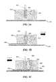
- FIG. 5A-5Cshow different configurations of a deposition head with a slot die.
- FIG. 6shows a top-down view of another 3D printing system with two cleaning zones.
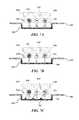
- FIG. 7A-7Cshow different configurations of the cleaning zone.
- FIG. 8shows a top-down view of a different 3D printing system with two containers.
- FIG. 9shows a top-down view of another different 3D printing system with a sensor.
- FIG. 10shows a computer system that is programmed or otherwise configured to implement methods provided herein.
- three-dimensional objectgenerally refers to an object or a part that is printed by 3D printing.
- the 3D objectmay be at least a portion of a larger 3D object or an entirety of the 3D object.
- the 3D objectmay be fabricated (e.g., printed) in accordance with a computer model of the 3D object.
- open platformgenerally refers to a structure that supports a liquid or a film of the liquid during 3D printing.
- the liquidmay have a viscosity that is sufficient to permit the liquid to remain on or adjacent to the open platform during 3D printing.
- the open platformmay be flat.
- the open platformmay include an optically transparent or semitransparent print window (e.g., glass or a polymer) to direct light through the window and to the liquid or the film of the liquid.
- the open platformmay have various shapes.
- the open platformmay be a rectangle or a ring, for example.
- the open platformmay comprise one or more walls adjacent to the open platform, such as at least 1, 2, 3, or 4 walls.
- the wallsmay enclose the open platform.
- a propertye.g., viscosity
- a liquid used for printingmay be sufficient to keep the fluid adjacent to the open platform without sufficient flow of the fluid towards the one or more walls.
- the wallsprevent flow of the liquid out of the open platform.
- the open platformmay include one or more sides that are not bounded.
- the open platformmay not be vat or a container.
- the open platformmay not be part of a vat or a container.
- the open platformmay be a substrate or slab that does not have a depression (e.g., vat or container) for retaining a liquid. In such situations, the liquid may be sufficiently viscous such that the liquid remains on the open platform.
- viscous liquidgenerally refers to a material that is usable to print a 3D object.
- the viscous liquidmay be referred to as a resin.
- the viscous liquidmay be dispensed from a nozzle and over a print window.
- the viscous liquidmay have a viscosity sufficient to be self-supporting on the print window without flowing or sufficient flowing.
- the viscosity of the viscous liquidmay range between about 4,000 centipoise (cP) to about 2,000,000 cP.
- the viscous liquidmay be pressed (e.g., by a blade or a build head) into a film of the viscous liquid on or over the print window.
- a thickness of the film of the viscous liquidmay be adjustable.
- the viscous liquidmay include a photoactive resin.
- the photoactive resinmay include a polymerizable and/or cross-linkable component (e.g., a precursor) and a photoinitiator that activates curing of the polymerizable and/or cross-linkable component, to thereby subject the polymerizable and/or cross-linkable component to polymerization and/or cross-linking.
- the photoactive resinmay include a photoinhibitor that inhibits curing of the polymerizable and/or cross-linkable component.
- the viscous liquidmay include a plurality of particles (e.g., metal, non-metal, or both)—in such a case, the viscous liquid may be a slurry or a photopolymer slurry.
- the viscous liquidmay be a paste.
- the plurality of particlesmay be added to the viscous liquid.
- the plurality of particlesmay be solids or semi-solids (e.g., gels). Examples of non-metal material include ceramic, polymeric, or composite material.
- the plurality of particlesmay be suspended throughout the viscous liquid.
- the plurality of particles in the viscous liquidmay have a distribution that is monodisperse or polydisperse.
- the viscous liquidmay contain additional optical absorbers and/or non-photoreactive components (e.g., fillers, binders, plasticizers, etc.).
- the 3D printingmay be performed with at least 1, 2, 3, 4, 5, 6, 7, 8, 9, 10 or more viscous liquids.
- a plurality of viscous liquids comprising different materialse.g., different photoactive resin and/or different plurality of particles may be used for printing a multi-material 3D object.
- the term “particles,” as used here,generally refers to any particulate material that may be melted or sintered (e.g., not completely melted).
- the particulate materialmay be in powder form.
- the particlesmay be inorganic materials.
- the inorganic materialsmay be metallic (e.g., aluminum or titanium), intermetallic (e.g., steel alloys), ceramic (e.g., metal oxides) materials, or any combination thereof.
- the term “metal” or “metallic”may refer to both metallic and intermetallic materials.
- the metallic materialsmay include ferromagnetic metals (e.g., iron and/or nickel).
- the particlesmay have various shapes and sizes.
- a particlemay be in the shape of a sphere, cuboid, or disc, or any partial shape or combination of shapes thereof.
- the particlemay have a cross-section that is circular, triangular, square, rectangular, pentagonal, hexagonal, or any partial shape or combination of shapes thereof.
- the particlesmay sinter (or coalesce) into a solid or porous object that may be at least a portion of a larger 3D object or an entirety of the 3D object.
- the 3D printingmay be performed with at least 1, 2, 3, 4, 5, 6, 7, 8, 9, 10 or more types of particles.
- the term “deposition head,” as used herein,generally refers to a part that may move across an open platform.
- the deposition headmay move across the open platform and deposit a film of a viscous liquid over a print window of the open platform.
- the film of the viscous liquidmay have a uniform thickness across the print window.
- the thickness of the filmmay be adjustable.
- the deposition headmay be coupled to a motion stage adjacent to the open platform.
- the deposition headmay have at least one nozzle to dispense at least one liquid (e.g., viscous liquid) over the print window.
- the deposition headmay have at least one wiper to form the layer of the viscous liquid or remove any excess viscous liquid from the print window.
- the deposition headmay have at least one actuator to adjust a distance between the at least one wiper the print window.
- the deposition headmay have a slot die.
- the deposition headmay retrieve any excess viscous liquid from the print window, contain the excess resin within the deposition head, and/or recycle the retrieved viscous liquid when printing subsequent portions of the 3D object.
- the deposition headmay clean the print window.
- the 3D printingmay be performed with at least 1, 2, 3, 4, 5, 6, 7, 8, 9, 10 or more deposition heads.
- Each of a plurality of deposition headsmay be in fluid communication with a separate source of viscous liquid.
- the plurality of deposition headsmay be used to deposit and cure alternating films of different viscous liquids (e.g., different photoactive resins and/or different inorganic particles). Compartmentalizing different viscous liquids in separate sources and separate deposition heads may improve printing speed and prevent cross-contamination of the different viscous liquids.
- nozzlegenerally refers to a component of the deposition head that directs the viscous liquid towards the open platform comprising the window.
- the nozzlemay include an opening for the viscous liquid to enter and an additional opening for the viscous liquid to exit.
- the nozzlemay not comprise any contraction or control mechanism to adjust flow of the viscous liquid towards the open platform.
- the nozzlemay comprise a contraction or control mechanism to adjust the flow of the viscous liquid towards the open platform.
- wipergenerally refers to a part that may be in contact with a print window of an open platform, a viscous liquid, or another wiper.
- the wipermay be a component of a deposition head.
- the wipermay be in contact with a viscous liquid to press the viscous liquid into a film.
- the wipermay be in contact with the print window to remove any excess viscous liquid.
- a distance between the wiper and the print windowmay be adjustable.
- the wipermay be a component in a cleaning zone.
- the wipermay be in contact with another wiper to remove any excess viscous liquid.
- the wipermay have various shapes, sizes, and surface textures.
- the wipermay be a blade (e.g., a squeegee blade, a doctor blade), roller, or rod (e.g., wire wound rod), for example.
- the 3D printingmay be performed with at least 1, 2, 3, 4, 5, 6, 7, 8, 9, 10 or more wipers.
- the bladeis part of the nozzle or attached to the nozzle.
- photoinitiationgenerally refers to a process of subjecting a portion of a film of a liquid (e.g., viscous liquid) to a light to cure a photoactive resin in the portion of the film of the liquid.
- the lightmay have a wavelength that activates a photoinitiator that initiates curing of a polymerizable and/or cross-linkable component in the photoactive resin.
- photoinhibitiongenerally refers to a process of subjecting a portion of a film of a liquid (e.g., a viscous liquid) to a light to inhibit curing of a photoactive resin in the portion of the film of the liquid.
- the lightmay have a wavelength that activates a photoinhibitor that inhibit curing of a polymerizable and/or cross-linkable component in the photoactive resin.
- the wavelength of the photoinhibition light and another wavelength of a photoinitiation lightmay be different.
- the photoinhibition light and the photoinitiation lightmay be projected from the same optical source.
- the photoinhibition light and the photoinitiation lightmay be projected from different optical sources.
- green bodygenerally refers to a 3D object that has a polymeric material and a plurality of particles (e.g., metal, ceramic, or both) that are encapsulated by the polymeric material.
- the plurality of particlesmay be in a polymer (or polymeric) matrix.
- the plurality of particlesmay be capable of sintering or melting.
- the green bodymay be self-supporting.
- the green bodymay be heated in a heater (e.g., in a furnace) to burn off at least a portion of the polymeric material and coalesce the plurality of particles into at least a portion of a larger 3D object or an entirety of the 3D object.
- the present disclosureprovides methods and systems for forming a 3D object. Such methods may employ application of a film of a liquid adjacent to an open platform and exposing the film to light to subject at least a portion of the film to polymerization and/or cross-linking.
- the 3D objectmay be based on a computer model of the 3D object, such as a computer-aided design (CAD) stored in a non-transitory computer storage medium (e.g., medium).
- CADcomputer-aided design
- the present disclosureprovides a system for printing a three-dimensional (3D) object.
- the systemmay comprise an open platform configured to hold a film of a viscous liquid comprising a photoactive resin.
- the open platformmay comprise a print window (also “window”).
- the systemmay comprise a deposition head comprising a nozzle in fluid communication with a source of the viscous liquid.
- the deposition headmay be configured to move across the open platform and deposit the film of the viscous liquid over the print window.
- the systemmay comprise an optical source that provides light through the print window for curing at least a portion of the film of the viscous liquid.
- the systemmay comprise a controller operatively coupled to the deposition head.
- the controllermay be programmed to (i) direct the deposition head to move across the open platform and dispense the viscous liquid through the nozzle to deposit the film over the print window, and (ii) direct the optical source to provide the light to cure the photoactive resin in at least the portion of the film of the viscous liquid, thereby printing at least a portion of the 3D object.
- the print windowmay be precluded.
- lightmay be provided to the film of the viscous liquid from above the open platform, such as directly above or from a side of the open platform.
- the windowmay be the open platform or part of the open platform. For example, at least about 10 percent (%), 15%, 20%, 25%, 30%, 35%, 40%, 45%, 50%, 55%, 60%, 65%, 70%, 75%, 80%, 85%, 90%, 95%, or more of open platform may comprise the window. As another example, at most about 95%, 90%, 85%, 80%, 75%, 70%, 65%, 60%, 55%, 50%, 45%, 40%, 35%, 30%, 25%, 20%, 15%, 10%, or less of the open platform may comprise the window. In some cases, the open platform may be the window. A surface of the open platform comprising the window may be flat.
- the windowmay be transparent or semitransparent (translucent).
- the windowmay be comprised of an optical window material, such as, for example, glass or a polymeric material (e.g., polymethylmethacrylate (PMMA)).
- the windowmay be comprised of polydimethylsiloxane (PDMS) that is permeable to oxygen.
- PDMSpolydimethylsiloxane
- the oxygen dissolved in the windowmay (i) diffuse into a contact surface between the window and the viscous liquid comprising the photoactive resin (the window-viscous liquid interface) and (ii) inhibit curing of the photoactive resin at the contact surface.
- the windowmay be positioned above the optical source for photopolymer-based 3D printing using bottom-up illumination.
- the windowmay be positioned below the optical source.
- the windowmay be positioned between a first optical source and a second optical source.
- the optical sourcemay provide the light through the print window (or above the print window) for curing the at least a portion of the film of the viscous liquid adjacent to the window.
- the optical source or another optical sourcemay provide another light through the print window (or above the print window) for inhibiting curing of at least a portion of the film of the viscous liquid.
- the viscous liquidmay be used for printing the at least the portion of the 3D object.
- the viscous liquidmay comprise a photoactive resin to form a polymeric material.
- the photoactive resinmay comprise a polymeric precursor of the polymeric material.
- the photoactive resinmay comprise at least one photoinitiator that is configured to initiate formation of the polymeric material from the polymeric precursor.
- the photoactive resinmay comprise at least one photoinhibitor that is configured to inhibit formation of the polymeric material from the polymeric precursor.
- the viscous liquidmay comprise a plurality of particles for forming the at least the portion of the 3D object.
- the viscous liquidmay be the photoactive resin.
- the viscosity of the photoactive resinmay range between about 4,000 cP to about 2,000,000 cP.
- the viscosity of the photoactive resinmay be at least about 4,000 cP, 10,000 cP, 20,000 cP, 30,000 cP, 40,000 cP, 50,000 cP, 60,000 cP, 70,000 cP, 80,000 cP, 90,000 cP, 100,000 cP, 200,000 cP, 300,000 cP, 400,000 cP, 500,000 cP, 600,000 cP, 700,000 cP, 800,000 cP, 900,000 cP, 1,000,000 cP, 2,000,000 cP, or more.
- the viscosity of the photoactive resinmay be at most about 2,000,000 cP, 1,000,000 cP, 900,000 cP, 800,000 cP, 700,000 cP, 600,000 cP, 500,000 cP, 400,000 cP, 300,000 cP, 200,000 cP, 100,000 cP, 90,000 cP, 80,000 cP, 70,000 cP, 60,000 cP, 50,000 cP, 40,000 cP, 30,000 cP, 20,000 cP, 10,000 cP, 4,000 cP, or less.
- the viscous liquidmay be a non-Newtonian fluid.
- the viscosity of the viscous liquidmay vary based on a shear rate or shear history of the viscous liquid.
- the viscous liquidmay be a Newtonian fluid.
- the viscous liquidmay comprise the photoactive resin and the plurality of particles.
- the viscosity of the viscous liquidmay range between about 4,000 cP to about 2,000,000 cP.
- the viscosity of the viscous liquidmay be at least about 4,000 cP, 10,000 cP, 20,000 cP, 30,000 cP, 40,000 cP, 50,000 cP, 60,000 cP, 70,000 cP, 80,000 cP, 90,000 cP, 100,000 cP, 200,000 cP, 300,000 cP, 400,000 cP, 500,000 cP, 600,000 cP, 700,000 cP, 800,000 cP, 900,000 cP, 1,000,000 cP, 2,000,000 cP, or more.
- the viscosity of the viscous liquidmay be at most about 2,000,000 cP, 1,000,000 cP, 900,000 cP, 800,000 cP, 700,000 cP, 600,000 cP, 500,000 cP, 400,000 cP, 300,000 cP, 200,000 cP, 100,000 cP, 90,000 cP, 80,000 cP, 70,000 cP, 60,000 cP, 50,000 cP, 40,000 cP, 30,000 cP, 20,000 cP, 10,000 cP, 4,000 cP, or less.
- the photoactive resinmay be present in an amount ranging between about 5 volume % (vol %) to about 80 vol % in the viscous liquid.
- the photoactive resinmay be present in an amount of at least about 5 vol %, 6 vol %, 7 vol %, 8 vol %, 9 vol %, 10 vol %, 11 vol %, 12 vol %, 13 vol %, 14 vol %, 15 vol %, 16 vol %, 17 vol %, 18 vol %, 19 vol %, 20 vol %, 21 vol %, 22 vol %, 23 vol %, 24 vol %, 25 vol %, 30 vol %, 35 vol %, 40 vol %, 45 vol %, 50 vol %, 55 vol %, 60 vol %, 65 vol %, 70 vol %, 75 vol %, 80 vol %, or more in the viscous liquid.
- the photoactive resinmay be present in an amount of at most about 80 vol %, 75 vol %, 70 vol %, 65 vol %, 60 vol %, 55 vol %, 50 vol %, 45 vol %, 40 vol %, 35 vol %, 30 vol %, 25 vol %, 24 vol %, 23 vol %, 22 vol %, 21 vol %, 20 vol %, 19 vol %, 18 vol %, 17 vol %, 16 vol %, 15 vol %, 14 vol %, 13 vol %, 12 vol %, 11 vol %, 10 vol %, 9 vol %, 8 vol %, 7 vol %, 6 vol %, 5 vol %, or less in the viscous liquid.
- the polymeric precursor in the photoactive resinmay comprise monomers to be polymerized into the polymeric material, oligomers to be cross-linked into the polymeric material, or both.
- the monomersmay be of the same or different types.
- An oligomermay comprise two or more monomers that are covalently linked to each other.
- the oligomermay be of any length, such as at least 2 (dimer), 3 (trimer), 4 (tetramer), 5 (pentamer), 6 (hexamer), 7, 8, 9, 10, 20, 30, 40, 50, 100, 200, 300, 400, 500, or more monomers.
- the polymeric precursormay include a dendritic precursor (monodisperse or polydisperse).
- the dendritic precursormay be a first generation (G1), second generation (G2), third generation (G3), fourth generation (G4), or higher with functional groups remaining on the surface of the dendritic precursor.
- the resulting polymeric materialmay comprise a monopolymer and/or a copolymer.
- the copolymermay be a linear copolymer or a branched copolymer.
- the copolymermay be an alternating copolymer, periodic copolymer, statistical copolymer, random copolymer, and/or block copolymer.
- Examples of monomersinclude one or more of hydroxyethyl methacrylate; n-Lauryl acrylate; tetrahydrofurfuryl methacrylate; 2,2,2-trifluoroethyl methacrylate; isobornyl methacrylate; polypropylene glycol monomethacrylates, aliphatic urethane acrylate (i.e., Rahn Genomer 1122); hydroxyethyl acrylate; n-Lauryl methacrylate; tetrahydrofurfuryl acrylate; 2,2,2-trifluoroethyl acrylate; isobornyl acrylate; polypropylene glycol monoacrylates; trimethylpropane triacrylate; trimethylpropane trimethacrylate; pentaerythritol tetraacrylate; pentaerythritol tetraacrylate; triethyleneglycol diacrylate; triethylene glycol dimethacrylate; tetrathylene
- Polymeric precursorsmay be present in an amount ranging between about 3 weight % (wt %) to about 90 wt % in the photoactive resin of the viscous liquid.
- the polymeric precursorsmay be present in an amount of at least about 3 wt %, 4 wt %, 5 wt %, 10 wt %, 15 wt %, 20 wt %, 25 wt %, 30 wt %, 35 wt %, 40 wt %, 45 wt %, 50 wt %, 55 wt %, 60 wt %, 65 wt %, 70 wt %, 75 wt %, 80 wt %, 85 wt %, 90 wt %, or more in the photoactive resin of the viscous liquid.
- the polymeric precursorsmay be present in an amount of at most about 90 wt %, 85 wt %, 80 wt %, 75 wt %, 70 wt %, 65 wt %, 60 wt %, 55 wt %, 50 wt %, 45 wt %, 40 wt %, 35 wt %, 30 wt %, 25 wt %, 20 wt %, 15 wt %, 10 wt %, 5 wt %, 4 wt %, 3 wt %, or less in the photoactive resin of the viscous liquid.
- Photopolymerization of the polymeric precursors into the polymeric materialmay be controlled by one or more photoactive species, such as the at least one photoinitiator and the at least one photoinhibitor.
- the at least one photoinitiatormay be a photon-absorbing compound that (i) is activated by a first light comprising a first wavelength and (ii) initiates photopolymerization of the polymeric precursors.
- the at least one photoinhibitormay be another photon-absorbing compound that (i) is activated by a second light comprising a second wavelength and (ii) inhibits the photopolymerization of the polymeric precursors.
- the first wavelength and the second wavelengthmay be different.
- the first light and the second lightmay be directed by the same light source.
- the first lightmay be directed by a first light source and the second light may be directed by a second light source.
- the first lightmay comprise wavelengths ranging between about 420 nanometers (nm) to about 510 nm.
- the second lightmay comprise wavelengths ranging between about 350 nm to about 410 nm.
- the first wavelength to induce photoinitiationis about 460 nm.
- the second wavelength to induce photoinhibitionis about 365 nm.
- Relative rates of the photoinitiation by the at least one photoinitiator and the photoinhibition by the at least one photoinhibitormay be controlled by adjusting the intensity and/or duration of the first light, the second light, or both. By controlling the relative rates of the photoinitiation and the photoinhibition, an overall rate and/or amount (degree) of polymerization of the polymeric precursors into the polymeric material may be controlled. Such process may be used to (i) prevent polymerization of the polymeric precursors at the window-viscous liquid interface, (ii) control the rate at which polymerization takes place in the direction away from the window, and/or (iii) control a thickness of the polymeric material within the film of the viscous liquid.
- Examples of types of the at least one photoinitiatorinclude one or more of benzophenones, thioxanthones, anthraquinones, benzoylformate esters, hydroxyacetophenones, alkylaminoacetophenones, benzil ketals, dialkoxyacetophenones, benzoin ethers, phosphine oxides acyloximino esters, alphahaloacetophenones, trichloromethyl-S-triazines, titanocenes, dibenzylidene ketones, ketocoumarins, dye sensitized photoinitiation systems, maleimides, and mixtures thereof.
- Examples of the at least one photoinitiator in the photoactive resininclude one or more of 1-hydroxy-cyclohexyl-phenyl-ketone (IrgacureTM 184; BASF, Hawthorne, N.J.); a 1:1 mixture of 1-hydroxy-cyclohexyl-phenyl-ketone and benzophenone (IrgacureTM 500; BASF); 2-hydroxy-2-methyl-1-phenyl-1-propanone (DarocurTM 1173; BASF); 2-hydroxy-1[4-(2-hydroxyethoxy)phenyl]-2-methyl-1-propanone (IrgacureTM 2959; BASF); methyl benzoylformate (DarocurTM MBF; BASF); oxy-phenyl-acetic acid 2-[2-oxo-2-phenyl-acetoxy-ethoxy]-ethyl ester; oxy-phenyl-acetic 2-[2-hydroxy-ethoxy]-ethyl ester; a mixture
- the at least one photoinitiatormay be present in an amount ranging between about 0.1 wt % to about 10 wt % in the photoactive resin.
- the at least one photoinitiatormay be present in an amount of at least about 0.1 wt %, 0.2 wt %, 0.3 wt %, 0.4 wt %, 0.5 wt %, 0.6 wt %, 0.7 wt %, 0.8 wt %, 0.9 wt %, 1 wt %, 2 wt %, 3 wt %, 4 wt %, 5 wt %, 6 wt %, 7 wt %, 8 wt %, 9 wt %, 10 wt %, or more in the photoactive resin.
- the at least one photoinitiatormay be present in an amount of at most about 10 wt %, 9 wt %, 8 wt %, 7 wt %, 6 wt %, 5 wt %, 4 wt %, 3 wt %, 2 wt %, 1 wt %, 0.9 wt %, 0.8 wt %, 0.7 wt %, 0.6 wt %, 0.5 wt %, 0.4 wt %, 0.3 wt %, 0.2 wt %, 0.1 wt %, or less in the photoactive resin.
- the at least one photoinhibitor in the photoactive resinmay comprise one or more radicals that may preferentially terminate growing polymer radicals, rather than initiating polymerization of the polymeric precursors.
- types of the at least one photoinitiatorinclude: one or more of sulfanylthiocarbonyl and other radicals generated in photoiniferter polymerizations; sulfanylthiocarbonyl radicals used in reversible addition-fragmentation chain transfer polymerization; and nitrosyl radicals used in nitroxide mediate polymerization.
- Other non-radical species that can be generated to terminate growing radical chainsmay include the numerous metal/ligand complexes used as deactivators in atom-transfer radical polymerization (ATRP).
- additional examples of the types of the at least one photoinhibitorinclude: one or more of thiocarbamates, xanthates, dithiobenzoates, hexaarylbiimidazoles, photoinitiators that generate ketyl and other radicals that tend to terminate growing polymer chains radicals (i.e., camphorquinone (CQ) and benzophenones), ATRP deactivators, and polymeric versions thereof.
- CQcamphorquinone
- ATRP deactivatorsand polymeric versions thereof.
- Examples of the at least one photoinhibitors in the photoactive resininclude one or more of zinc dimethyl dithiocarbamate; zinc diethyl dithiocarbamate; zinc dibutyl dithiocarbamate; nickel dibutyl dithiocarbamate; zinc dibenzyl dithiocarbamate; tetramethylthiuram disulfide; tetraethylthiuram disulfide (TEDS); tetramethylthiuram monosulfide; tetrabenzylthiuram disulfide; tetraisobutylthiuram disulfide; dipentamethylene thiuram hexasulfide; N,N′-dimethyl N,N′-di(4-pyridinyl)thiuram disulfide; 3-Butenyl 2-(dodecylthiocarbonothioylthio)-2-methylpropionate; 4-Cyano-4-[(dodecylsulf
- the at least one photoinhibitormay be present in an amount ranging between about 0.1 wt % to about 10 wt % in the photoactive resin.
- the at least one photoinhibitormay be present in an amount of at least about 0.1 wt %, 0.2 wt %, 0.3 wt %, 0.4 wt %, 0.5 wt %, 0.6 wt %, 0.7 wt %, 0.8 wt %, 0.9 wt %, 1 wt %, 2 wt %, 3 wt %, 4 wt %, 5 wt %, 6 wt %, 7 wt %, 7 wt %, 8 wt %, 9 wt %, 10 wt %, or more in the photoactive resin.
- the at least one photoinhibitormay be present in an amount of at most about 10 wt %, 9 wt %, 8 wt %, 7 wt %, 6 wt %, 5 wt %, 4 wt %, 3 wt %, 2 wt %, 1 wt %, 0.9 wt %, 0.8 wt %, 0.7 wt %, 0.6 wt %, 0.5 wt %, 0.4 wt %, 0.3 wt %, 0.2 wt %, 0.1 wt %, or less in the photoactive resin.
- the photoactive resinmay include a co-initiator.
- the co-initiatormay be used to enhance the polymerization rate of the polymeric precursors.
- Suitable classes of the co-initiatorsmay include: primary, secondary, and tertiary amines; alcohols; and thiols.
- co-initiatorsmay include: one or more of isoamyl 4-(dimethylamino)benzoate, 2-ethylhexyl 4-(dimethylamino)benzoate; ethyl 4-(dimethylamino)benzoate (EDMAB); 3-(dimethylamino)propyl acrylate; 2-(dimethylamino)ethyl methacrylate; 4-(dimethylamino)benzophenones, 4-(diethyl amino)benzophenones; 4,4′-Bis(diethylamino)benzophenones; methyl diethanolamine; triethylamine; hexane thiol; heptane thiol; octane thiol; nonane thiol; decane thiol; undecane thiol; dodecane thiol; isooctyl 3-mercaptopropionate; pent
- the at least one photoinitiator and the co-initiatormay be activated by the same light.
- the at least one photoinitiator and the co-initiatormay be activated by the same wavelength and/or two different wavelengths of the same light.
- the at last one photoinitiator and the co-initiatormay be activated by different lights comprising different wavelengths.
- the systemmay comprise a co-initiator light source configured to direct a co-initiation light comprising a wavelength sufficient to activate the co-initiator to the film of the viscous liquid.
- the co-initiatormay be a small molecule (e.g., a monomer). Alternatively or in addition to, the co-initiator may be an oligomer or polymer comprising a plurality of small molecules. The co-initiator may be present in an amount ranging between about 0.1 wt % to about 10 wt % in the photoactive resin.
- the co-initiatormay be present in an amount of at least about 0.1 wt %, 0.2 wt %, 0.3 wt %, 0.4 wt %, 0.5 wt %, 0.6 wt %, 0.7 wt %, 0.8 wt %, 0.9 wt %, 1 wt %, 2 wt %, 3 wt %, 4 wt %, 5 wt %, 6 wt %, 7 wt %, 8 wt %, 9 wt %, 10 wt %, or more in the photoactive resin.
- the co-initiatormay be present in an amount of at most about 10 wt %, 9 wt %, 8 wt %, 7 wt %, 6 wt %, 5 wt %, 4 wt %, 3 wt %, 2 wt %, 1 wt %, 0.9 wt %, 0.8 wt %, 0.7 wt %, 0.6 wt %, 0.5 wt %, 0.4 wt %, 0.3 wt %, 0.2 wt %, 0.1 wt %, or less in the photoactive resin.
- the photoactive resinmay comprise one or more dyes.
- the one or more dyesmay be used to attenuate light, to transfer energy to the photoactive species, or both.
- the one or more dyesmay transfer energy to the photoactive species to increase sensitivity of the photoactive resin to the first light for the photoinitiation process, the second light for the photoinhibition process, or both.
- the photoactive resincomprises at least one dye configured to absorb the second light having the second wavelength, which second wavelength is for activating the at least one photoinhibitor.
- Exposing the photoactive resin to the second lightmay initiate the at least one dye to absorb the second light and (i) reduce an amount of the second light exposed to the at least one photoinhibitor, thereby controlling the depth of penetration of the second light into the film of the viscous liquid, and/or (ii) transfer (e.g., via Förster resonance energy transfer (FRET)) some of the absorbed energy from the second light to the at least one photoinhibitor, thereby improving the efficiency of photoinhibition.
- the one or more dyesmay include compounds commonly used as ultraviolet (UV) light absorbers, including 2-hydroxyphenyl-benzophenones, 2-(2-hydroxyphenyl)-benzotriazoles, and 2-hydroxyphenyl-s-triazines.
- the one or more dyesmay include those used for histological staining or dying of fabrics, including Martius yellow, Quinoline yellow, Sudan red, Sudan I, Sudan IV, eosin, eosin Y, neutral red, and acid red.
- a concentration of the one or more dyes in the photoactive resinmay be dependent on the light absorption properties of the one or more dyes.
- the one or more dyesmay be present in an amount ranging between about 0.1 wt % to about 10 wt % in the photoactive resin.
- the one or more dyesmay be present in an amount of at least about 0.1 wt %, 0.2 wt %, 0.3 wt %, 0.4 wt %, 0.5 wt %, 0.6 wt %, 0.7 wt %, 0.8 wt %, 0.9 wt %, 1 wt %, 2 wt %, 3 wt %, 4 wt %, 5 wt %, 6 wt %, 7 wt %, 8 wt %, 9 wt %, 10 wt %, or more in the photoactive resin.
- the one or more dyesmay be present in an amount of at most about 10 wt %, 9 wt %, 8 wt %, 7 wt %, 6 wt %, 5 wt %, 4 wt %, 3 wt %, 2 wt %, 1 wt %, 0.9 wt %, 0.8 wt %, 0.7 wt %, 0.6 wt %, 0.5 wt %, 0.4 wt %, 0.3 wt %, 0.2 wt %, 0.1 wt %, or less in the photoactive resin.
- the viscous liquidmay comprise the plurality of particles for forming the at least the portion of the 3D object.
- the amount of the plurality of particles in the viscous liquidmay be sufficient to minimize shrinking of the green body during sintering.
- the plurality of particlesmay comprise any particulate material (a particle) that can be melted or sintered (e.g., not completely melted).
- the particulate materialmay be in powder form.
- the particular materialmay be inorganic materials.
- the inorganic materialsmay be metallic, intermetallic, ceramic materials, or any combination thereof.
- the one or more particlesmay comprise at least one metallic material, at least one intermetallic material, at least one ceramic material, or any combination thereof.
- powdered metalsalone may be a severe safety hazard and may explode and/or require extensive safety infrastructures
- using powdered metals that are dispersed in the viscous liquidmay avoid or substantially reduce the risks relevant to using the powdered metals that are not dispersed in a liquid medium.
- photopolymer-based 3D printing using the viscous liquid comprising the photoactive resin and the powdered metalsmay be performed without using heat, thereby avoiding or substantially reducing thermal distortion to the at least the portion of the 3D object during printing.
- the metallic materials for the particlesmay include one or more of aluminum, calcium, magnesium, barium, scandium, titanium, vanadium, chromium, manganese, iron, cobalt, nickel, copper, zinc, yttrium, niobium, molybdenum, ruthenium, rhodium, silver, cadmium, actinium, and gold.
- the particlesmay comprise a rare earth element.
- the rare earth elementmay include one or more of scandium, yttrium, and elements of the lanthanide series having atomic numbers from 57-71.
- An intermetallic materialmay be a solid-state compound exhibiting metallic bonding, defined stoichiometry and ordered crystal structure (i.e., alloys).
- the intermetallic materialsmay be in prealloyed powder form. Examples of such prealloyed powders may include, but are not limited to, brass (copper and zinc), bronze (copper and tin), duralumin (aluminum, copper, manganese, and/or magnesium), gold alloys (gold and copper), rose-gold alloys (gold, copper, and zinc), nichrome (nickel and chromium), and stainless steel (iron, carbon, and additional elements including manganese, nickel, chromium, molybdenum, boron, titanium, silicon, vanadium, tungsten, cobalt, and/or niobium).
- the prealloyed powdersmay include superalloys.
- the superalloysmay be based on elements including iron, nickel, cobalt, chromium, tungsten, molybdenum, tantalum, niobium, titanium, and/or aluminum.
- the ceramic materialsmay comprise metal (e.g., aluminum, titanium, etc.), non-metal (e.g., oxygen, nitrogen, etc.), and/or metalloid (e.g., germanium, silicon, etc.) atoms primarily held in ionic and covalent bonds.
- metale.g., aluminum, titanium, etc.
- non-metale.g., oxygen, nitrogen, etc.
- metalloide.g., germanium, silicon, etc.
- examples of the ceramic materialsinclude, but are not limited to, an aluminide, boride, beryllia, carbide, chromium oxide, hydroxide, sulfide, nitride, mullite, kyanite, ferrite, titania zirconia, yttria, and magnesia.
- the viscous liquidmay comprise a pre-ceramic material.
- the pre-ceramic materialmay be a polymer that can be heated (or pyrolyzed) to form a ceramic material.
- the pre-ceramic materialmay include polyorganozirconates, polyorganoaluminates, polysiloxanes, polysilanes, polysilazanes, polycarbosilanes, polyborosilanes, etc.
- pre-ceramic materialexamples include zirconium tetramethacrylate, zirconyl dimethacrylate, or zirconium 2-ethylhexanoate; aluminum III s-butoxide, aluminum III diisopropoxide-ethylacetoacetate; 1,3-bis(chloromethyl) 1,1,3,3-Tetrakis(trimethylsiloxy)disiloxane; 1,3-bis(3-carboxypropyl)tetramethyldisiloxane; tetraethyl-2,4,6,8-tetramethylcyclotetrasilazane; tris(trimethylsilyl)phosphate; tris(trimethylsiloxy)boron; and mixtures thereof.
- a cross-sectional dimension of the plurality of particlesmay range between about 1 nanometers (nm) to about 500 micrometers ( ⁇ m).
- the cross-sectional dimension of the plurality of particlesmay be at least about 1 nm, 2 nm, 3 nm, 4 nm, 5 nm, 6 nm, 7 nm, 8 nm, 9 nm, 10 nm, 20 nm, 30 nm, 40 nm, 50 nm, 60 nm, 70 nm, 80 nm, 90 nm, 100 nm, 200 nm, 300 nm, 400 nm, 500 nm, 600 nm, 700 nm, 800 nm, 900 nm, 1 ⁇ m, 2 ⁇ m, 3 ⁇ m, 4 ⁇ m, 5 ⁇ m, 6 ⁇ m, 7 ⁇ m, 8 ⁇ m, 9 ⁇ m, 10 ⁇ m, 20 ⁇ m, 30 ⁇ m, 40 ⁇ m,
- the cross-sectional dimension of the plurality of particlesmay be at most about 500 ⁇ m, 400 ⁇ m, 300 ⁇ m, 200 ⁇ m, 100 ⁇ m, 90 ⁇ m, 80 ⁇ m, 70 ⁇ m, 60 ⁇ m, 50 ⁇ m, 40 ⁇ m, 30 ⁇ m, 20 ⁇ m, 10 ⁇ m, 9 ⁇ m, 8 ⁇ m, 7 ⁇ m, 6 ⁇ m, 5 ⁇ m, 4 ⁇ m, 3 ⁇ m, 2 ⁇ m, 1 ⁇ m, 900 nm, 800 nm, 700 nm, 600 nm, 500 nm, 400 nm, 300 nm, 200 nm, 100 nm, 90 nm, 80 nm, 70 nm, 60 nm, 50 nm, 40 nm, 30 nm, 20 nm, 10 nm, 9 nm, 8 nm, 7 nm, 6 nm, 5 nm, 4 nm, 3
- the plurality of particlesmay be present in an amount ranging between about 5 vol % to about 90 vol % in the viscous liquid.
- the plurality of particlesmay be present in an amount of at least about 5 vol %, 10 vol %, 15 vol %, 20 vol %, 25 vol %, 30 vol %, 35 vol %, 40 vol %, 45 vol %, 50 vol %, 55 vol %, 60 vol %, 65 vol %, 70 vol %, 75 vol %, 80 vol %, 85 vol %, 90 vol %, or more in the viscous liquid.
- the plurality of particlesmay be present in an amount of at most about 90 vol %, 85 vol %, 80 vol %, 75 vol %, 70 vol %, 65 vol %, 60 vol %, 55 vol %, 50 vol %, 45 vol %, 40 vol %, 35 vol %, 30 vol %, 25 vol %, 20 vol %, 15 vol %, 10 vol %, 5 vol %, or less in the viscous liquid.
- the viscosity ( ⁇ mix ) of the viscous liquid comprising the plurality of particlesmay be dependent on a critical volume fraction (V C ) of the plurality of particles in the viscous liquid and the viscosity of the polymeric precursor ( ⁇ 0 ), as shown in Equation 1:
- the critical volume fraction (V C )may be defined as the largest amount of one or more solid materials (e.g., the plurality of particles) that can be added to a mixture (e.g., the viscous liquid) and still allow the mixture to flow freely.
- the critical volume fraction (V C )may be substantially the same or lower than the maximum packing density (or maximum packing fraction) of non-ordered particles in a given space (e.g., the viscous liquid).
- the maximum packing density of non-ordered, monodisperse spherical particlesmay range between about 60% to about 70%.
- the maximum packing density of non-ordered, monodisperse spherical particlesmay be about 64%. In some cases, the maximum packing density of non-ordered, non-spherical particles may be lower than that of the non-ordered, monodisperse spherical particles.
- the maximum packing density of the non-ordered, non-spherical particlese.g., cuboids, fibers
- the maximum packing density of non-ordered, non-spherical particlesmay be at least about 2%, 5%, 10%, 15%, 20%, 25%, 30%, 35%, 40%, 45%, 50%, 55%, 60%, or more in the viscous liquid.
- the maximum packing density of non-ordered, non-spherical particlesmay be at most about 60%, 55%, 50%, 45%, 40%, 35%, 30%, 25%, 20%, 15%, 10%, 5%, 2%, or less in the viscous liquid.
- the maximum packing density of gas or water atomized metal powders that are polydisperse in sizes and non-spherical in shapemay range between about 40% to about 60% in the viscous liquid.
- the maximum packing density of the polydisperse, non-spherical gas atomized metal powdersmay be at least about 40%, 41%, 42%, 43%, 44%, 45%, 46%, 47%, 48%, 49%, 50%, 51%, 52%, 53%, 54%, 55%, 56%, 57%, 58%, 59%, 60%, or more in the viscous liquid.
- the maximum packing density of the polydisperse, non-spherical gas atomized metal powdersmay be at most about 60%, 59%, 58%, 57%, 56%, 55%, 54%, 53%, 52%, 51%, 50%, 49%, 48%, 47%, 46%, 45%, 44%, 43%, 42%, 41%, 40%, or less in the viscous liquid.
- the maximum packing density of milled metal (e.g., titanium, tungsten, aluminum, etc.) particlesmay be about 5% to about 55% in the viscous liquid.
- the maximum packing density of milled metal particlesmay be at least about 5%, 10%, 15%, 20%, 25%, 30%, 35%, 40%, 45%, 50%, 55%, or more in the viscous liquid.
- the maximum packing density of milled metal particlesmay be at most about 55%, 50%, 45%, 40%, 35%, 30%, 25%, 20%, 15%, 10%, 5%, or less in the viscous liquid.
- the maximum packing density of milled titanium particlesis about 45% in a viscous liquid.
- the maximum packing density of milled tungsten particlesis about 15% in a viscous liquid.
- the maximum packing density of milled aluminum particlesis about 41% in a viscous liquid.
- the first light having the first wavelengthmay be directed from the light source through the window and into the viscous liquid to cure the polymeric precursor into the polymeric material.
- a thickness (l) of a printed layer comprising the polymeric materialmay be described as a function of the transmitted energy (E) from the first light, the energy required for curing (E C ), and the penetration depth (d p ) of the first light into the viscous liquid, as shown in Equation 2:
- the penetration depth (d p ) of the first lightmay be less than the cross-sectional dimension of the plurality of the particles. Since the thickness (l) of the printed layer may not be thinner than the largest cross-sectional dimension of the plurality of particles, the amount of the transmitted energy (E) from the first light may need to be at least about 3 times greater than the energy required for curing (E C ). The amount of the transmitted energy (E) from the first light may be at least about 3, 4, 5, 6, 7, 8, 9, 10, 11, 12, 13, 14, 15, 16, 17, 18, 19, 20 times or more than the energy required for curing (E C ).
- a curing inhibition layer(an inhibition layer) may be formed at the viscous liquid-window interface by shining the second light comprising the second wavelength into the viscous liquid adjacent to the window.
- the second lightmay activate the at least one photoinhibitor that can inhibit curing of the polymeric precursor at the viscous liquid-window interface, thereby preventing adhesion of the cured polymeric material to the window.
- the viscous liquidmay comprise an anti-settling component to prevent settling of the plurality of particles and keep them suspend in the viscous liquid.
- the anti-settling componentmay sterically limit the plurality of particles from moving closer to each other.
- the anti-settling componentmay not scatter light (e.g., the first light and/or the second light) to avoid negatively affecting the penetration depth of the light into the viscous liquid.
- the anti-settling componentmay be present in an amount ranging between about 5 vol % to about 90 vol % in the viscous liquid.
- the anti-settling componentmay be present in an amount of at least about 5 vol %, 10 vol %, 15 vol %, 20 vol %, 25 vol %, 30 vol %, 35 vol %, 40 vol %, 45 vol %, 50 vol %, 55 vol %, 60 vol %, 65 vol %, 70 vol %, 75 vol %, 80 vol %, 85 vol %, 90 vol %, or more in the viscous liquid.
- the anti-settling componentmay be present in an amount of at most about 90 vol %, 85 vol %, 80 vol %, 75 vol %, 70 vol %, 65 vol %, 60 vol %, 55 vol %, 50 vol %, 45 vol %, 40 vol %, 35 vol %, 30 vol %, 25 vol %, 20 vol %, or less in the viscous liquid.
- the plurality of particlesare present in an amount below the critical volume fraction (V C ) in the viscous liquid, and the anti-settling component may be added to approximately reach the critical volume fraction (V C ) in the viscous liquid.
- anti-settling componentexamples include, but are not limited to, one or more additional particles and a thixotropic additive.
- the one or more additional particlesmay be configured to prevent settling of the plurality of particles in the viscous liquid.
- the one or more additional particlesmay decrease free space and increase the overall packing density within the viscous liquid, thereby preventing the plurality of particles from settling towards the window during printing.
- the one or more additional particlesinclude micronized and/or dispersed waxes such as paraffin, carnuba, montan, Fischer tropsch wax, ethylene bis stearamide, and lignin; micronized polymers such as cellulose, high density polyethylene, polyethylene, polypropylene, oxidized polyethylene (PE), paraformaldehyde, polyethylene glycol, phenolics, and melamine-formaldehyde based materials; and microspheres made from crosslinked polystyrene, polymethyl methacrylate, and/or other copolymers.
- An example of the one or more additional particlesis Byk Ceraflour 929 (micronized, modified polyethylene wax).
- the thixotropic additivemay be a gel-like or static material that becomes fluid-like when physically disturbed. Such property may be reversible.
- the thixotropic additivemay be configured to create a network to prevent settling of the plurality of particles.
- the network of the thixotropic additivemay be easily disturbed by shearing (e.g., dispensing through the nozzle) the viscous liquid to allow flow.
- shearinge.g., dispensing through the nozzle
- the thixotropic additivemay form another network within the viscous liquid to prevent settling of the plurality of particles during printing.
- the thixotropic additiveinclude castor wax, oxidized polyethylene wax, amide wax, modified ureas, castor oil derivatives, fumed silica and alumina, Bentonite clays, and mixtures thereof.
- the anti-settling component of the viscous liquidmay be the one or more additional particles, the thixotropic additive, or both.
- the viscous liquidmay comprise at least one additional additive that is configured to prevent foaming (or induce deaeration) of the viscous liquid. Preventing foaming of the viscous liquid may improve quality of the resulting 3D object.
- the at least one additional additivemay be an amphiphilic material.
- the at least one additional additivemay be a low surface energy material to allow association with each other within the viscous liquid. Such association of the at least one additional additive may trap air bubbles present inside the viscous liquid, migrate towards the viscous liquid-air interface, and release the air bubbles.
- the at least one additional additivemay polymerize and/or cross-link with the polymeric precursor. Examples of the one additional additive include silcones, modified silicones, lauryl acrylates, hydrophobic silicas, and modified ureas.
- An example of the one additional additivemay be Evonik Tegorad 2500 (silicon acrylate).
- the viscous liquidmay comprise an extractable material.
- the extractable materialmay be soluble in the polymeric precursor and/or dispersed throughout the viscous liquid.
- curing of the polymeric precursor of the photoactive resin of the at least the portion of the viscous liquidmay create a first solid phase comprising the polymeric material and a second solid phase comprising the extractable material within the at least the portion of the 3D object.
- Such processmay be a polymerization-induced phase separation (PIPS) step.
- PIPSpolymerization-induced phase separation
- At least a portion of the plurality of particlesmay be encapsulated by the first solid phase comprising the polymeric material.
- the at least the portion of the 3D objectmay be a green body that can be heated to sinter at least a portion of the plurality of particles and burn off at least a portion of other components (i.e., organic components).
- the green bodyPrior to sintering the plurality of particles, the green body may be treated (e.g., immersed, jetted, etc.) with a solvent (liquid or vapor).
- the solventmay be an extraction solvent.
- the extractable materialmay be soluble in the solvent.
- a first solubility of the extractable material in the solventmay be higher than a second solubility of the polymeric material in the solvent.
- the solventmay be a poor solvent for the polymeric material.
- treating the green body with the solventmay solubilize and extract at least a portion of the extractable material out of the green body into the solvent, and create one or more pores in the at least the portion of the 3D object.
- the one or more poresmay be a plurality of pores.
- the green bodymay be treated with the solvent and heat at the same time.
- the one or more poresmay create at least one continuous porous network in the at least the portion of the 3D object.
- Such processmay be a solvent de-binding step.
- the deposition headmay be configured to move across the open platform and deposit the film of the viscus liquid over the print window.
- the film of the viscous liquidmay have a thickness ranging between about 1 ⁇ m to about 1000 ⁇ m.
- the film of the viscous liquidmay have a thickness of at least about 1 ⁇ m, 2 ⁇ m, 3 ⁇ m, 4 ⁇ m, 5 ⁇ m, 6 ⁇ m, 7 ⁇ m, 8 ⁇ m, 9 ⁇ m, 10 ⁇ m, 20 ⁇ m, 30 ⁇ m, 40 ⁇ m, 50 ⁇ m, 60 ⁇ m, 70 ⁇ m, 80 ⁇ m, 100 ⁇ m, 200 ⁇ m, 300 ⁇ m, 400 ⁇ m, 500 ⁇ m, 600 ⁇ m, 700 ⁇ m, 800 ⁇ m, 900 ⁇ m, 1000 ⁇ m, or more.
- the film of the viscous liquidmay have a thickness of at most about 1000 ⁇ m, 900 ⁇ m, 800 ⁇ m, 700 ⁇ m, 600 ⁇ m, 500 ⁇ m, 400 ⁇ m, 300 ⁇ m, 200 ⁇ m, 100 ⁇ m, 90 ⁇ m, 80 ⁇ m, 70 ⁇ m, 60 ⁇ m, 50 ⁇ m, 40 ⁇ m, 30 ⁇ m, 20 ⁇ m, 10 ⁇ m, 9 ⁇ m, 8 ⁇ m, 7 ⁇ m, 6 ⁇ m, 5 ⁇ m, 4 ⁇ m, 3 ⁇ m, 2 ⁇ m, 1 ⁇ m, or less.
- the thickness of the film of the viscous liquidmay have a tolerance ranging between about 1 ⁇ m to about 10 ⁇ m.
- the thickness of the film of the viscous liquidmay have a tolerance of at least about 1 ⁇ m, 2 ⁇ m, 3 ⁇ m, 4 ⁇ m, 5 ⁇ m, 6 ⁇ m, 7 ⁇ m, 8 ⁇ m, 9 ⁇ m, 10 ⁇ m, or more.
- the thickness of the film of the viscous liquidmay have a tolerance of at most about 10 ⁇ m, 9 ⁇ m, 8 ⁇ m, 7 ⁇ m, 6 ⁇ m, 5 ⁇ m, 4 ⁇ m, 3 ⁇ m, 2 ⁇ m, 1 ⁇ m, or less.
- the viscous liquidmay be stored in the source of the viscous liquid.
- the source of the viscous liquidmay be a cup, container, syringe, or any other repository that can hold the viscous liquid.
- the source of the viscous liquidmay in fluid communication (e.g., via a passageway) with the nozzle in the deposition head.
- the source of the viscous liquidmay be connected to a flow unit.
- the flow unitmay provide and control flow of the viscous liquid from the source of the viscous liquid towards the nozzle, thereby dispensing the viscous liquid.
- the flow unitmay provide and control flow of the viscous liquid in a direction away from the nozzle and towards the source of the viscous liquid, thereby retrieving the viscous liquid.
- the flow unitmay use pressure mechanisms to control the speed and direction of the flow of the viscous liquid.
- the flow unitmay be a syringe pump, vacuum pump, an actuator (e.g., linear, pneumatic, hydraulic, etc.), a compressor, or any other suitable device to exert pressure (positive or negative) to the viscous liquid in the source of the viscous liquid.
- the controllermay be operatively coupled to the flow unit the control the speed, duration, and/or direction of the flow of the viscous liquid.
- the source of the viscous liquidmay comprise a sensor (e.g., an optical sensor) to detect the volume of the viscous liquid.
- the controllermay be operatively coupled to the sensor to determine when the source of the viscous liquid may be replenished with new viscous liquid.
- the source of the viscous liquidmay be removable. The controller may determine when the source of the viscous liquid may be replaced with a new source of the viscous liquid comprising with the viscous liquid.
- the deposition headmay comprise the nozzle.
- the nozzlemay be in fluid communication with the source of the viscous liquid.
- the deposition headmay dispense the viscous liquid over the print window through the nozzle as a process of depositing the film of the viscous liquid over the print window.
- the deposition headmay retrieve any excess viscous liquid from the print window back into the source of the viscous liquid through the nozzle.
- the source of the viscous liquidmay be connected to the flow unit to provide and control flow of the viscous liquid towards or away from the nozzle of the deposition head.
- the nozzlemay comprise a nozzle flow unit that provides and controls flow of the viscous liquid towards or away from the print window. Examples of the nozzle flow unit include a piezoelectric actuator and an auger screw that is connected to an actuator.
- the deposition headmay comprise a wiper.
- the wipermay be movable along a direction towards and/or away from the print window.
- the wipermay have a variable height relative to the print window.
- the deposition headmay comprise an actuator connected to the wiper to control movement of the wiper in a direction towards and away from the print window.
- the actuatormay be a mechanical, hydraulic, pneumatic, or electro-mechanical actuator.
- the controllermay be operatively coupled to the actuator to control the movement of the wiper in a direction towards and away from the print window.
- a vertical distance between the wiper and the print window(e.g., a distance perpendicular to the print window) may be static.
- the deposition headmay comprise a plurality of wipers with different configurations.
- the deposition headmay comprise the nozzle and three wipers.
- the wiper of the deposition headmay be configured to (i) reduce or inhibit flow of the viscous liquid out of the deposition head, (ii) flatten the film of the viscous liquid, and/or (iii) remove any excess of theviscous liquid.
- the wipermay be configured to be in contact with the print window and reduce or inhibit flow of the viscous liquid out of the deposition head.
- the wipermay be movable along a direction away from the print window and configured to flatten the film of the viscous liquid.
- the wipermay flatten the film of the viscous liquid to a defined height (or thickness).
- the wipermay be movable along a direction away from the print window and configured to remove the excess of the viscous liquid.
- the wipermay comprise polymer (e.g., rubber, silicone), metal, or ceramic.
- the wipermay comprise (e.g., entirely or as a coating) one or more fluoropolymers that prevent adhesion of the viscous liquid on the wiper.
- Examples of the one or more fluoropolymersinclude polyvinylidene fluoride (PVDF), ethylenchlorotrifluoroethylene (ECTFE), ethyl enetetrafluoroethylene (ETFE), polytetrafluoroethylene (PTFE), perfluoroalkoxy (PFA), and modified fluoroalkoxy (a copolymer of tetrafluoroethylene and perfluoromethylvinylether, also known as MFA).
- PVDFpolyvinylidene fluoride
- ECTFEethylenchlorotrifluoroethylene
- ETFEethyl enetetrafluoroethylene
- PTFEpolytetrafluoroethylene
- PFAperfluoroalkoxy
- modified fluoroalkoxya copolymer of tetrafluoroethylene and perfluoromethylvinylether, also known as MFA.
- the wiper of the deposition headmay be a blade (e.g., a squeegee blade, a doctor blade).
- the blademay have various shapes.
- the blademay be straight and/or curved.
- the wipermay be a straight blade with a flat surface.
- the wipermay be a straight blade with a curved surface.
- the wipermay be a curved blade (curved along the long axis of the wiper) with a flat surface.
- the wipermay be a curved blade (curved along the long axis of the wiper) with a curved surface.
- the wipermay comprise at least one straight portion and at least one curved portion along its length.
- the wipermay be a blade comprising a straight central portion between two curved portions.
- the wipermay be a straight blade and configured perpendicular to the print window.
- the wipermay be a straight blade with a flat surface, and tilted at an angle.
- the tilted straight blademay concentrate the excess resin at the bottom of the blade.
- the straight blademay be tilted at an angle ranging between about 1 degree to about 50 degrees.
- the straight blademay be tilted at an angle of at least about 1 degree, 2 degrees, 3 degrees, 4 degrees, 5 degrees, 6 degrees, 7 degrees, 8 degrees, 9 degrees, 10 degrees, 20 degrees, 30 degrees, 40 degrees, 50 degrees, or more.
- the straight blademay be tiled at an angle of at most about 50 degrees, 40 degrees, 30 degrees, 20 degrees, 10 degrees, 9 degrees, 8 degrees, 7 degrees, 6 degrees, 5 degrees, 4 degrees, 3 degrees, 2 degrees, 1 degree, or less.
- the wipermay be a straight blade with a curved surface (a curved blade).
- a curved bladeWhen the deposition head moves to remove any excess viscous liquid from the print window, the curved blade may concentrate the excess resin in the center of the concave surface of the wiper. The curved blade may reduce or prevent the excess resin from spilling out from the sides of the blade.
- a radius of curvature of the surface of the blademay range between about 10 millimeter (mm) to about 1000 mm.
- the radius of curvature of the surface of the blademay be at least about 10 mm, 20 mm, 30 mm, 40 mm, 50 mm, 60 mm, 70 mm, 80 mm, 90 mm, 100 mm, 200 mm, 300 mm, 400 mm, 500 mm, 1000 mm, or more.
- the radius of curvature of the surface of the blademay be at most about 1000 mm, 500 mm, 400 mm, 300 mm, 200 mm, 100 mm, 90 mm, 80 mm, 70 mm, 60 mm, 50 mm, 40 mm, 30 mm, 20 mm, 10 mm, or less.
- the wiper of the deposition headmay be a roller.
- the rollermay have a surface that is flat or textured.
- the rollermay be configured to rotate clockwise and/or counterclockwise while the deposition head moves across the print window.
- the rollermay be configured to be static while the deposition head moves across the print window.
- the wiper of the deposition headmay be a rod.
- the rodmay have a surface that is flat or textured.
- the rodmay be configured to rotate clockwise and/or counterclockwise while the deposition head moves across the print window.
- the rodmay be configured to be static while the deposition head moves across the print window.
- the rodmay be a wire wound rod, also known as a Meyer rod.
- the deposition headmay comprise a slot die.
- the slot diemay be configured to move along a direction away from the print window.
- the slot diemay be height adjustable with respect to the print window.
- the slot diemay comprise a channel in fluid communication with the source of the viscous liquid.
- the channelmay comprise a first opening to receive the viscous liquid from the source of the viscous liquid.
- the channelmay comprise a second opening opposite of the first opening to dispense the viscous liquid to the print window.
- the second openingmay be an injection point.
- the channelmay have a reservoir between the first and second openings to hold a volume of the viscous liquid.
- the injection point of the slot diemay comprise a flat surface to flatten the film of the viscous liquid to a defined height (or thickness).
- the deposition head comprising the slot diemay include a separate nozzle to suction and retrieve any excess viscous liquid from the film of the viscous liquid during printing.
- the separate nozzle of the deposition head comprising the slot diemay be in fluid communication with a repository to collect the excess viscous liquid.
- the repositorymay be a recycling bin.
- the repositorymay also be in fluid communication with the slot die to send the excess viscous liquid collected in the repository back into the reservoir of the slot die. Alternatively or in addition to, the collected excess viscous liquid may be removed for reprocessing.
- the reprocessing of the collected excess viscous liquidmay comprise (i) filtering out any polymerized solid particulates, (ii) filtering out any of the plurality of particles that may be greater than a target particle size, (iii) remixing the viscous liquid to ensure homogeneity, and/or (iv) removing at least a portion of air entrapped in the viscous liquid.
- the at least the portion of air entrapped in the viscous liquidmay be removed by centrifuging the viscous liquid.
- the systemmay further comprise an additional deposition head comprising an additional nozzle.
- the additional nozzle of the additional deposition headmay be in fluid communication with an additional source of an additional viscous liquid.
- the nozzle of the deposition head of the systemmay be in fluid communication with the source of the viscous liquid and the additional source of the additional viscous liquid.
- the deposition headmay comprise a first nozzle in fluid communication with the source of the viscous liquid, and (b) a second nozzle in fluid communication with the additional source of the additional viscous liquid. The presence of the additional source of the additional viscous liquid may allow printing at least a portion of a 3D object comprising multiple materials (multi-materials) in different layers and/or in different portions within the same layer.
- the viscous liquid and the additional viscous liquidmay be the same.
- the viscous liquid and the additional viscous liquidmay be different.
- the viscous liquid and the additional viscous liquidmay comprise different types of the photoactive resin, the plurality of particles, or both.
- the viscous liquid and the additional viscous liquidmay comprise different amounts (concentrations by weight or volume) of the photoactive resin, the plurality of particles, or both.
- the viscous liquidmay comprise metallic particles
- the additional viscous liquidmay comprise ceramic particles. A first concentration of the metallic particles in the viscous liquid and a second concentration of the ceramic particles in the additional viscous liquid may be the same or different.
- a first photoactive resin in the viscous liquid and a second photoactive resin in the additional viscous liquidmay be the same or different.
- the viscous liquidmay comprise a first type of metallic particles, and the additional viscous liquid may comprise a second type of metallic particles.
- the viscous liquidmay comprise ceramic particles at a first concentration, and the additional viscous liquid may comprise the same ceramic particles at a second concentration that is different from the first concentration.
- the systemmay comprise a build head.
- the build headmay be configured to hold and/or support at least a portion (e.g., a layer) of the 3D object. During printing, the at least the portion of the 3D object may be printed on the build head.
- the build headmay be configured to move relative to the print window during printing.
- the build headmay be configured to move along
- the build headmay be connected to a build head actuator for moving the build head relative to the print window.
- the build head actuatormay be a mechanical, hydraulic, pneumatic, or electro-mechanical actuator.
- the open platform comprising the print windowmay be connected to an open platform actuator for moving the open platform relative to the build head.
- the open platform actuatormay be a mechanical, hydraulic, pneumatic, or electro-mechanical actuator.
- the controllermay be operatively coupled to the build head actuator and/or the open platform actuator to control the relative distance between the build head and the print window.
- the relative distance between the build head and the print windowmay be adjusted to adjust a thickness of a layer within the at least the portion of the 3D object.
- the systemmay comprise a cleaning zone.
- the cleaning zonemay be configured adjacent to the open platform.
- the cleaning zonemay be configured in a path of movement of the deposition head across the open platform.
- the cleaning zonemay be configured to clean the deposition head.
- Cleaning the deposition headmay (i) improve reliability and reproducibility of printing at least the portion of the 3D object, and (ii) reduce wear and tear of the deposition head.
- the deposition headmay be static or move relative to the cleaning zone while the cleaning zone cleans the deposition head.
- the cleaning zonemay comprise a wiper, a nozzle configured to provide at least one cleaning solvent, or both.
- the wiper of the cleaning zonemay be a blade (e.g., a doctor blade), a roller, or a rod.
- one or more wipers of the cleaning zonemay come in contact with one or more wipers of the deposition head and remove any excess resin remaining on the one or more wipers of the deposition head.
- one or more nozzles of the cleaning zonemay dispense or jet the at least one cleaning solvent to the one or more wipers of the deposition head for cleaning.
- the one or more nozzles of the cleaning zonemay be in fluid communication with at least one source of the at least one cleaning solvent. At least a portion of the viscous liquid may be soluble in the at least one cleaning solvent.
- the cleaning zonemay comprise a repository that can hold the excess viscous liquid that is removed from the deposition head and/or the at least one cleaning solvent.
- the systemmay comprise a repository (e.g., vat or container) adjacent to the open platform.
- the repositorymay be configured to collect the viscous liquid from the film of the deposition head.
- the repositorymay be configured to hold any excess viscous liquid that is removed from the print window by the deposition head. After removing any excess viscous liquid from the print window, the deposition head may move and use at least one wiper to collect the excess viscous liquid into the repository.
- the repositorymay be a recycling bin.
- the repositorymay be in fluid communication with the source of the viscous liquid to recycle the collected excess viscous liquid for printing. Alternatively or in addition to, the collected excess viscous liquid may be removed for reprocessing.
- the reprocessing of the collected excess viscous liquidmay comprise (i) filtering out any polymerized solid particulates, (ii) filtering out any of the plurality of particles that may be greater than a target particle size, (iii) remixing the viscous liquid to ensure homogeneity, and/or (iv) removing at least a portion of air entrapped in the viscous liquid.
- the at least the portion of air entrapped in the viscous liquidmay be removed by centrifuging the viscous liquid.
- the repositorymay comprise a sensor (e.g., an optical sensor or a weight scale) to detect when the repository is full and/or when an amount of the collected excess viscous liquid is above a predefined threshold.
- the systemmay comprise a sensor.
- the sensormay be configured to move across the open platform and/or measure a thickness of at least a portion of the film of the viscous liquid.
- the sensormay assess integrity of the film of the viscous liquid before inducing polymerization of the polymeric precursors in the photoactive resin in the film of the viscos liquid.
- the sensormay detect any variation in thickness across the film.
- the sensormay detect any irregularities (e.g., defects, empty spots, solid particles, etc.) in the film.
- the sensormay be configured to perform quality control after printing at least a portion (e.g., a layer) of the 3D object.
- the sensormay scan a remaining portion of the film of the viscous liquid after printing, and the controller that is operatively coupled to the sensor may determine if the previous printing process was successful or not.
- the sensormay be an optical profilometer (e.g., an in-line profilometer).
- the systemmay comprise a transparent film adjacent to the open platform and configured to hold the film of the viscous liquid.
- the transparent filmmay cover the print window.
- the transparent filmmay comprise one or more fluoropolymers that reduce adhesion of a cured portion of the viscous liquid on the transparent film.
- the one or more fluoropolymersinclude polyvinylidene fluoride (PVDF), ethylenchlorotrifluoroethylene (ECTFE), ethyl enetetrafluoroethylene (ETFE), polytetrafluoroethylene (PTFE), perfluoroalkoxy (PFA), and modified fluoroalkoxy (a copolymer of tetrafluoroethylene and perfluoromethylvinylether, also known as MFA).
- the transparent filmmay reduce or eliminate any undesirable force (e.g., a sliding or rotational mechanism) that may otherwise be needed to separate the cured portion of the viscous liquid and the print window. This may yield a reduced failure rate and increased printing speed.
- the systemmay comprise a motion stage adjacent to the open platform.
- the motion stagemay be coupled to the deposition head and configured to direct movement of the deposition head across the open platform.
- the motion stagemay be coupled to one or more other components of the system that move across the platform (e.g., an additional deposition head, a sensor, etc.).
- the motion stagemay be connected to an actuator that is configured to direct movement of the motion stage.
- the actuatormay be a mechanical, hydraulic, pneumatic, electro-mechanical, or magnetic actuator.
- the controllermay be operatively coupled to the actuator to control movement of the motion stage.
- the systemmay comprise an additional motion stage coupled to the open platform to direct movement of the open platform relative to other components of the system.
- the systemmay comprise the optical source that provides the light through the print window for curing the at least the portion of the film of the viscous liquid.
- the light of the optical sourcemay comprise a first wavelength for curing the photoactive resin in a first portion of the film of the viscous liquid.
- the first wavelengthmay activate the at least one photoinitiator of the photoactive resin, thereby initiating curing of the polymeric precursors into the polymeric material.
- the lightmay be a photoinitiation light, and the first portion of the film may be a photoinitiation layer.
- the optical sourcemay provide an additional light having a second wavelength for inhibiting curing of the photoactive resin in a second portion of the film of the viscous liquid.
- the first wavelength and the second wavelengthmay be different.
- the second wavelengthmay activate the at least one photoinhibitor of the photoactive resin, thereby inhibiting curing of the polymeric precursors into the polymeric material.
- the additional lightmay be a photoinhibition light
- the second portion of the film of the viscous liquidmay be a photoinhibition layer.
- a dual-wavelength projectore.g., a dual-wavelength laser
- the light of the optical sourcemay comprise a first wavelength for curing the photoactive resin in a first portion of the film of the viscous liquid.
- the first wavelengthmay activate the at least one photoinitiator of the photoactive resin, thereby initiating curing of the polymeric precursors into the polymeric material.
- the lightmay be a photoinitiation light, and the first portion of the film may be a photoinitiation layer.
- the lightmay be a patterned light.
- the systemmay further comprise an additional optical source comprising an additional light having a second wavelength for inhibiting curing of the photoactive resin in a second portion of the film of the viscous liquid. The first wavelength and the second wavelength may be different.
- the second wavelengthmay activate the at least one photoinhibitor of the photoactive resin, thereby inhibiting curing of the polymeric precursors into the polymeric material.
- the additional lightmay be a photoinhibition light, and the second portion of the film of the viscous liquid may be a photoinhibition layer.
- the additional lightmay be a flood light.
- the optical source that directs the photoinitiation lightmay be a mask-based display, such as a liquid crystal display (LCD) device, or light emitting, such as a discrete light emitting diode (LED) array device.
- the optical source that directs the photoinitiation lightmay be a digital light processing (DLP) device, including a digital micro-mirror device (DMD) for producing patterned light that can selectively illuminate and cure 3D printed structures.
- DLPdigital light processing
- DMDdigital micro-mirror device
- the initiation light directed from the DLP devicemay pass through one or more projection optics (e.g., a light projection lens) prior to illuminating through the print window and to the film of the viscous liquid.
- the one or more projection opticsmay be integrated in the DLP device.
- the one or more projection opticsmay be configured between the DLP device and the print window.
- a relative position of the one or more projection optics relative to the DLP device and the print windowmay be adjustable to adjust an area of the photoinitiation layer in the film of the viscous liquid.
- the area of the photoinitiation layermay be defined as a build area.
- the one or more projection opticsmay be on a projection optics platform.
- the projection optics platformmay be coupled to an actuator that directs movement of the projection optics platform.
- the controllermay be operatively coupled to the actuator to control movement of the projection optics platform.
- the controllermay direct the actuator (e.g., a screw-based mechanism) to adjust a relative position of the one or more projection optics to the DLP device and the print window during printing the 3D object.
- the additional optical source that directs the photoinhibition lightmay comprise a plurality of light devices (e.g., a plurality of light emitting diodes (LEDs)).
- the light devicesmay be on a light platform.
- the light platformmay be configured (i) move relative to the print window and (ii) yield a uniform projection of the photoinhibition light within the photoinhibition layer in the film of the viscous liquid adjacent to the print window.
- the position of the light platformmay be independently adjustable with respect to a position of the optical source that directs the photoinitiation light.
- the light platform comprising the plurality of light devicesmay be arranged with respect to the print window such that a peak intensity of each of the plurality of light devices is directed at a different respective position (e.g., corner or other position) of the build area.
- the build areamay have four corners and a separate beam of light (e.g., a separate LED) may be directed to each corner of the build area.
- the beams of photoinhibition light from the plurality of light devicesmay overlap to provide the uniform projection of the photoinhibition light within the photoinhibition layer.
- the light platformmay be coupled to an actuator that directs movement of the light platform.
- the controllermay be operatively coupled to the actuator to control movement of the light platform.
- the controllermay direct the actuator (e.g., a screw-based mechanism) to adjust a relative position of the plurality of light devices to the print window during printing the 3D object.
- the actuatore.g., a screw-based mechanism
- the one or more projection optics to the DLP devicemay be on the light platform.
- the photoinhibition lightmay be configured to create the photoinhibition layer in the film of the viscous liquid adjacent to the print window. In some cases, the photoinhibition light may be configured to form the photoinhibition layer in the film of the viscous liquid adjacent to the transparent film that is covering the print window. Furthermore, the photoinitiation light may be configured to cure the photoactive resin in the photoinitiation layer that resides between the photoinhibition layer and the build head. The photoactive resin in the photoinitiation layer may be cured into at least a portion of the 3D structure. In some cases, the photoinitiation light may be configured to cure the photoactive resin in the photoinitiation layer that resides between the photoinhibition layer and the at least the portion of the 3D structure adjacent to the build head.
- a thickness of the photoinitiation layer, the photoinhibition layer, or bothmay be adjusted by adjusting an intensity and duration of the photoinitiation light, the photoinhibition light, or both.
- the thickness of the photoinitiation layer, the photoinhibition layer, or bothmay be adjusted to adjust the thickness of the printed layer of the at least the portion of the 3D object.
- the thickness of the photoinitiation layer, the photoinhibition layer, or bothmay be adjusted by adjusting the speed at which the build head moves away in a direction away from the print window.
- the systemmay comprise the controller to control various parts (e.g., actuators, sensors, etc.) of different components of the 3D printing system, as described in detail above.
- various partse.g., actuators, sensors, etc.
- the present disclosureprovides a method for printing a 3D object.
- the methodmay comprise providing a deposition head adjacent to an open platform comprising a print window.
- the deposition headmay be movable across the open platform.
- the deposition headmay comprise a nozzle in fluid communication with a source of a viscous liquid comprising a photoactive resin.
- the deposition headmay comprise a wiper.
- the methodmay comprise moving the deposition head across the open platform and dispensing the viscous liquid through the nozzle to deposit a film of the viscous liquid over the print window.
- the methodmay comprise directing light through the print window to the film to cure the photoactive resin in at least a portion of the film, thereby printing at least a portion of the 3D object.
- the methodmay further comprise configuring the wiper to be in contact with the print window, and using the wiper to reduce or inhibit flow of the viscous liquid out of the deposition head while moving the deposition head to deposit the film.
- the methodmay further comprise configuring the wiper at a distance away from the print window, and using the wiper to flatten the film of the viscous liquid into a desired thickness while moving the deposition head.
- the desired thickness of the film of the viscous liquidmay be substantially the same as the distance between the wiper and the print window.
- the distance between the wiper and the print windowmay be adjustable.
- the thickness of the film of the viscous liquidmay be adjustable.
- the thickness of the filmmay be adjusted to control a thickness of the at least the portion of the 3D object.
- the methodmay further comprise moving the deposition head cross the open platform in a first direction, and using the wiper of the deposition head that is in contact with the print window to remove any excess of the viscous liquid from the print window.
- the deposition headmay further comprise an additional wiper. After moving the deposition head in the first direction and using the wiper to remove the excess of the viscous liquid from the print window, the method may further comprise moving the deposition head in the second direction opposite of the first direction and using the additional wiper to collect the excess of the viscous liquid between the additional wiper and the wiper within the deposition head.
- the excess of the viscous liquidmay be collected and used (recycled) to deposit an additional film of the viscous liquid over the print window.
- the nozzle of the deposition headmay dispense more viscous liquid into the collected excess of viscous liquid.
- the controllermay use a computer model of the 3D object, such as a computer-aided design (CAD) stored in a non-transitory computer storage medium, to determine theoretical amounts of (i) the viscous liquid used in a first printing step and (ii) the excess of the viscous liquid remaining on the print window.
- CADcomputer-aided design
- the controllermay also use the computer model of the 3D object to determine a theoretical amount of the viscous liquid needed to deposit a film of the viscous liquid for the second printing step. If the volume of the collected excess of viscous liquid is not sufficient for the second printing step, the controller may direct the nozzle to dispense more viscous liquid.
- the systemmay comprise a repository (e.g., vat or container) adjacent to the open platform. After each printing step, the deposition head may move to the repository and collect the excess viscous liquid into the repository. The collected excess viscous liquid may be reprocessed and used for printing.
- the deposition headmay be coupled to a motion stage adjacent to the open platform.
- the methodmay comprise moving the motion stage to move the deposition head across the open platform to at least deposit the film of the viscous liquid on the print window.
- the open platformmay have different shapes (e.g., rectangle or ring), and movement of the motion stage may have different shapes.
- the motion stagemay move linearly, thereby directing the deposition head in a first direction and/or in a second direction that is opposite to the first direction.
- the motion stagemay move circularly, thereby direction the deposition clockwise and/or counterclockwise.
- the methodmay comprise providing a build head for holding at least a portion of the 3D object. Prior to directing the light through the print window and to the film of the viscous liquid, the method may further comprise moving the build head towards the print window and bringing in contact with the film of the viscous liquid. Subsequent to directing the light to cure at least a portion of the photoactive resin in the film of viscous liquid between the print window and the build head, the method may further comprise moving the build head in a direction away from the print window. In some cases, the method may further comprise moving the build head in the direction away from the window while forming the 3D object. The rate of movement of the build head may be controlled to adjust a thickness of one or more layers in the 3D object.
- a surface of the build head in contact with a first layer of the 3D objectmay be smooth, knurled, or serrated to adjust contact surface area and/or frictional force between the surface and the first layer of the 3D object.
- the first layer of the 3D objectmay be a support layer for the 3D object that may be removed post-processing.
- the methodmay comprise using a plurality of viscous liquids for printing the 3D object.
- the methodmay comprise providing an additional deposition head comprising an additional nozzle.
- the additional nozzlemay be in fluid communication with an additional source of an additional viscous liquid.
- the methodmay further comprise moving the additional deposition head across the open platform and depositing a film of the additional viscous liquid over the print window.
- the methodmay comprise providing the additional source of the additional viscous liquid that is in fluid communication with the nozzle of the deposition head.
- the methodmay further comprise dispensing the additional viscous liquid through the nozzle to the print window during printing.
- the methodmay comprise providing the additional source of the additional viscous liquid that is in fluid communication with an additional nozzle in the deposition head.
- the methodmay further comprise dispensing the additional viscous liquid through the additional nozzle to the print window during printing.
- the methodmay comprise providing a cleaning zone adjacent to the open platform.
- the methodmay further comprise moving the deposition head to the cleaning zone and activating the cleaning zone to clean the deposition head.
- the deposition headmay be cleaned prior to depositing a new film of the viscous liquid.
- the deposition headmay be cleaned subsequent to printing at least a portion of the 3D object.
- the methodmay comprise providing a sensor (e.g., an optical profilometer) adjacent to the open platform.
- the methodmay further comprise moving the sensor across the open platform and using the sensor to measure a thickness of at least a portion of the film of the viscous liquid prior and/or subsequent to printing at least a portion of the 3D object.
- the sensormay detect an irregularity in the thickness and/or a defect (e.g., a hole) in the film of the viscous liquid, and the sensor may alert the controller to direct the deposition head to clean the print window and re-deposit the film of the viscous liquid.
- the methodmay comprise providing a transparent film adjacent to the print window.
- the transparent filmmay cover the print window.
- the transparent filmmay comprise one or more fluoropolymers that reduce adhesion of a cured portion of the viscous liquid on the transparent film.
- the methodmay further comprise directing the light through the print window, through the transparent film, and to the film of the viscous liquid to cure the photoactive resin in the at least the portion of the film of the viscous liquid, thereby printing at least a portion of the 3D object.
- the methodmay comprise using a plurality of wavelengths of light for printing at least a portion of the 3D object.
- the methodmay comprise directing the light comprising a first wavelength to cure the photoactive resin in a first portion of the film of the viscous liquid.
- the light comprising the first wavelengthmay activate at least one photoinitiator to initiate curing of polymeric precursors into a polymeric material to form the least the portion of the 3D object.
- the methodmay further comprise directing an additional light having a second wavelength to inhibit curing of the photoactive resin in a second portion of the film of the viscous liquid.
- the first wavelength and the second wavelengthmay be different.
- the additional lighthave a second wavelength may activate at least one photoinhibitor to inhibit curing of the polymeric precursors into the polymeric material in the second portion of the film adjacent to the print window.
- the methodmay comprise providing the light comprising the first wavelength using an optical source.
- the methodmay comprise providing the additional light comprising the second wavelength using an additional optical source.
- the methodmay further comprise adjusting a position of the additional optical source independently and relative to a position of the optical source.
- the methodmay further comprise providing a light platform to hold the additional optical source.
- the methodmay further comprise, prior to curing the photoactive resin in the first portion of the film of the viscous liquid, moving the light platform relative to the print window and yielding a uniform projection of the additional light within the second portion of the film of the viscous liquid adjacent to the print window.
- the methodmay comprise providing the light comprising the first wavelength and the additional light comprising the second wavelength by the same optical source.
- the present disclosureprovides a method for printing a 3D object.
- the methodmay comprise providing a resin (e.g., a viscous liquid) adjacent to a build surface (e.g., the open platform comprising the print window).
- the resinmay comprise a polymeric precursor.
- the resinmay comprise at least one photoinitiator that is configured to initiate formation of a polymeric material from the polymeric precursor.
- the resinmay comprise at least one photoinhibitor that is configured to inhibit formation of the polymeric material from the polymeric precursor.
- the resinmay comprise a plurality of particles (e.g., metallic, intermetallic, and/or ceramic particles) for forming at least a portion of the 3D object.
- the methodmay comprise exposing the resin (e.g., the viscous liquid) to a first light under conditions sufficient to cause the at least one photoinitiator to initiate formation of the polymeric material from the polymeric precursor.
- the polymeric materialmay encapsulate the plurality of particles.
- the methodmay comprise exposing the resin to a second light under conditions sufficient to cause the at least one photoinhibitor to inhibit formation of the polymeric material adjacent to the build surface.
- the plurality of particles encapsulated in the polymeric materialmay be usable for forming at least a portion the 3D object.
- the methodmay further comprise repeating, one or more times, (a) providing the resin to the build surface and (b) exposing the resin to (i) the first light to initiate the formation of the polymeric material in and (ii) the second light to inhibit the formation of the polymeric material adjacent to the build surface.
- the first lightmay comprise a first wavelength and the second light may comprise a second wavelength.
- the first and second wavelengthsmay be different.
- the first wavelengthmay be sufficient to activate the at least one photoinitiator, and the second wavelength may be sufficient to activate the at least one photoinhibitor.
- the first lightmay be a photoinitiation light, and the second light may be a photoinhibition light.
- the methodmay further comprise providing a build head adjacent to the build surface.
- the at least the portion of the 3D objectmay be formed adjacent to the build head. Additional portions of the 3D object may be formed adjacent to the at least the portion of the 3D object on the build head.
- the build headmay be moved along a direction away from the build surface.
- the controller operatively coupled to the build headmay be used to adjust a relative distance between the build head and the build surface, thereby adjusting a thickness of a photoinhibition layer within the resin adjacent to the build surface, a photoinitiation layer between the photoinhibition layer and the build head, or both.
- the build surfacemay comprise an optically transparent window. Accordingly, the method may comprise exposing the resin to the photoinitiation light and/or the photoinhibition light through the optically transparent window.
- the polymeric precursor of the resinmay comprise monomers. Accordingly, the method may comprise exposing the resin to the first light to induce polymerization of the monomers to generate the polymeric material. Alternatively or in addition to, the polymeric precursor of the resin may comprise oligomers. Accordingly, the method may comprise exposing the resin to the first light to induce cross-linking between the oligomers to generate the polymeric material.
- the resinmay further comprise at least one dye (e.g., an ultraviolet (UV) absorber) configured to absorb the second light (the photoinhibition light).
- the methodmay comprise exposing the resin to the second light to initiate the at least one dye to reduce an amount of the second light exposed to the at least one photoinhibitor in at least a portion of the resin.
- at least one dyee.g., an ultraviolet (UV) absorber
- the methodmay further comprise removing the green body from the build head.
- the green bodymay be separated from the build head by inserting a thin material (e.g. a steel blade) between the green body and the build head.
- a first layer of the green body that is in contact with the build headmay not comprise the plurality of particles for easy removal from the build head by the thin material.
- the methodmay further comprise washing the green body.
- the green bodymay be washed by jetting a solvent (e.g., isopropanol) to remove any excess polymeric precursor.
- a solvente.g., isopropanol
- the methodmay further comprise subjecting the green body comprising at least the polymeric material to heating (e.g., in a furnace), to thereby heat at least the plurality of particles encapsulated in the at least the polymeric material.
- the heatingmay be under conditions sufficient to sinter the plurality of particles to form a final product that is at least a portion of a 3D object or an entire 3D object.
- the organic componentse.g., the polymeric material, additives, etc.
- the green bodymay be heated in a processing chamber.
- the temperature of the processing temperaturemay be regulated with at least one heater.
- the processing chambermay be an oven or a furnace.
- the oven or furnacemay be heated with various heating approaches, such as resistive heating, convective heating and/or radiative heating. Examples of the furnace include an induction furnace, electric arc furnace, gas-fired furnace, plasma arc furnace, microwave furnace, and electric resistance furnace. Such heating may be employed at a fixed or variating heating rate from an initial temperature to a target temperature or temperature range.
- a green body comprising metallic and/or intermetallic particlesmay be heated from room temperature to a processing temperature.
- the processing temperaturemay be kept constant or substantially constant for a given period of time, or may be adjusted to one or more other temperatures.
- the processing temperaturemay be selected based on the material of the particles in the green body (e.g., the processing temperature may be higher for material having a higher melting point than other materials).
- the processing temperaturemay be sufficient to sinter but not completely melt the particles in the green body. As an alternative, the processing temperature may be sufficient to melt the particles in the green body.
- the processing temperature for heatingmay range between about 300 degrees Celsius to about 2200 degrees Celsius.
- the processing temperature for sintering the green bodymay be at least about 300 degrees Celsius, 350 degrees Celsius, 400 degrees Celsius, 450 degrees Celsius, 500 degrees Celsius, 550 degrees Celsius, 600 degrees Celsius, 650 degrees Celsius, 700 degrees Celsius, 750 degrees Celsius, 800 degrees Celsius, 850 degrees Celsius, 900 degrees Celsius, 950 degrees Celsius, 1000 degrees Celsius, 1050 degrees Celsius, 1100 degrees Celsius, 1150 degrees Celsius, 1200 degrees Celsius, 1250 degrees Celsius, 1300 degrees Celsius, 1350 degrees Celsius, 1400 degrees Celsius, 1450 degrees Celsius, 1500 degrees Celsius, 1550 degrees Celsius, 1600 degrees Celsius, 1700 degrees Celsius, 1800 degrees Celsius, 1900 degrees Celsius, 2000 degrees Celsius, 2100 degrees Celsius, 2200 degrees Celsius, or more.
- the processing temperature for sintering the green bodymay be at most about 2200 degrees Celsius, 2100 degrees Celsius, 2000 degrees Celsius, 1900 degrees Celsius, 1800 degrees Celsius, 1700 degrees Celsius, 1600 degrees Celsius, 1550 degrees Celsius, 1500 degrees Celsius, 1450 degrees Celsius, 1400 degrees Celsius, 1350 degrees Celsius, 1300 degrees Celsius, 1250 degrees Celsius, 1200 degrees Celsius, 1150 degrees Celsius, 1100 degrees Celsius, 1050 degrees Celsius, 1000 degrees Celsius, 950 degrees Celsius, 900 degrees Celsius, 850 degrees Celsius, 800 degrees Celsius, 750 degrees Celsius, 700 degrees Celsius, 650 degrees Celsius, 600 degrees Celsius, 550 degrees Celsius, 500 degrees Celsius, 450 degrees Celsius, 400 degrees Celsius, 350 degrees Celsius, 300 degrees Celsius, or less.
- a green body comprising aluminum particlesmay be heated from room temperature to a processing temperature ranging between about 350 degrees Celsius to about 700 degrees Celsius.
- a green body comprising copper particlesmay be heated from room temperature to a processing temperature of about 1000 degrees Celsius.
- a green body comprising stainless steel particlesmay be heated from room temperature to a processing temperature ranging between about 1200 degrees Celsius to about 1500 degrees Celsius.
- a green body comprising other tool steel particlesmay be heated from room temperature to a processing temperature of about 1250 degrees Celsius.
- a green body comprising tungsten heavy alloy particlesmay be heated from room temperature to a processing temperature of about 1500 degrees Celsius.
- the temperature of the processing chambermay change at a rate ranging between about 0.1 degrees Celsius per minute (degrees Celsius/min) to about 200 degrees Celsius/min.
- the temperature of the processing chambermay change at a rate of at least about 0.1 degrees Celsius/min, 0.2 degrees Celsius/min, 0.3 degrees Celsius/min, 0.4 degrees Celsius/min, 0.5 degrees Celsius/min, 1 degrees Celsius/min, 2 degrees Celsius/min, 3 degrees Celsius/min, 4 degrees Celsius/min, 5 degrees Celsius/min, 6 degrees Celsius/min, 7 degrees Celsius/min, 8 degrees Celsius/min, 9 degrees Celsius/min, 10 degrees Celsius/min, 20 degrees Celsius/min, 50 degrees Celsius/min, 100 degrees Celsius/min, 150 degrees Celsius/min, 200 degrees Celsius/min, or more.
- the temperature of the processing chambermay change at a rate of at most about 200 degrees Celsius/min, 150 degrees Celsius/min, 100 degrees Celsius/min, 50 degrees Celsius/min, 20 degrees Celsius/min, 10 degrees Celsius/min, 9 degrees Celsius/min, 8 degrees Celsius/min, 7 degrees Celsius/min, 6 degrees Celsius/min, 5 degrees Celsius/min, 4 degrees Celsius/min, 3 degrees Celsius/min, 2 degrees Celsius/min, 1 degrees Celsius/min, 0.5 degrees Celsius/min, 0.4 degrees Celsius/min, 0.3 degrees Celsius/min, 0.2 degrees Celsius/min, 0.1 degrees Celsius/min, or less.
- the processmay comprise holding at a fixed temperature between room temperature and the processing temperature for a time ranging between about 1 min to about 240 min.
- the sintering processmay comprise holding at a fixed temperature for at least about 10 min, 20 min, 30 min, 40 min, 50 min, 60 min, 90 min, 120 min, 150 min, 180 min, 210 min, 240 min, or more.
- the sintering processmay comprise holding at a fixed temperature for at most about 240 min, 210 min, 180 min, 150 min, 120 min, 90 min, 60 min, 50 min, 40 min, 30 min, 20 min, 10 min, 1 min, or less.
- the temperaturemay not be held at a processing temperature for an extended period of time (e.g., once a target temperature is reached, the temperature may be reduced).
- the sintering processmay increase the temperature to a first temperature and immediately (e.g., without holding at the first temperature for a period of time) lower the temperature to a second temperature that is lower than the first temperature.
- a green body comprising ceramic particlesmay be heated from room temperature to a processing temperature ranging between about 900 degrees Celsius to about 2000 degrees Celsius.
- the processing temperaturemay be kept constant or substantially constant for a given period of time, or may be adjusted to one or more other temperatures.
- the processing temperature for sintering the green body (including the particles)may be at least about 900 degrees Celsius, 950 degrees Celsius, 1000 degrees Celsius, 1050 degrees Celsius, 1100 degrees Celsius, 1150 degrees Celsius, 1200 degrees Celsius, 1300 degrees Celsius, 1400 degrees Celsius, 1500 degrees Celsius, 1600 degrees Celsius, 1700 degrees Celsius, 1800 degrees Celsius, 1900 degrees Celsius, 2000 degrees Celsius, or more.
- the processing temperature for sintering the green bodymay be at most about 2000 degrees Celsius, 1900 degrees Celsius, 1800 degrees Celsius, 1700 degrees Celsius, 1600 degrees Celsius, 1500 degrees Celsius, 1400 degrees Celsius, 1300 degrees Celsius, 1200 degrees Celsius, 1150 degrees Celsius, 1100 degrees Celsius, 1050 degrees Celsius, 1000 degrees Celsius, 950 degrees Celsius, 900 degrees Celsius, or less.
- a green body comprising alumina particlesmay be heated from room temperature to a processing temperature ranging between about 1500 degrees Celsius to about 1950 degrees Celsius.
- a green body comprising cemented carbide particlesmay be heated from room temperature to a processing temperature ranging between about 1700 degrees Celsius.
- a green body comprising zirconia particlesmay be heated from room temperature to a processing temperature ranging between about 1100 degrees Celsius.
- the temperature of the processing chambermay change at a rate ranging between about 0.1 degrees Celsius per minute (degrees Celsius/min) to about 200 degrees Celsius/min.
- the temperature of the processing chambermay change at a rate of at least about 0.1 degrees Celsius/min, 0.2 degrees Celsius/min, 0.3 degrees Celsius/min, 0.4 degrees Celsius/min, 0.5 degrees Celsius/min, 1 degrees Celsius/min, 2 degrees Celsius/min, 3 degrees Celsius/min, 4 degrees Celsius/min, 5 degrees Celsius/min, 6 degrees Celsius/min, 7 degrees Celsius/min, 8 degrees Celsius/min, 9 degrees Celsius/min, 10 degrees Celsius/min, 20 degrees Celsius/min, 50 degrees Celsius/min, 100 degrees Celsius/min, 150 degrees Celsius/min, 200 degrees Celsius/min, or more.
- the temperature of the processing chambermay change at a rate of at most about 200 degrees Celsius/min, 150 degrees Celsius/min, 100 degrees Celsius/min, 50 degrees Celsius/min, 20 degrees Celsius/min, 10 degrees Celsius/min, 9 degrees Celsius/min, 8 degrees Celsius/min, 7 degrees Celsius/min, 6 degrees Celsius/min, 5 degrees Celsius/min, 4 degrees Celsius/min, 3 degrees Celsius/min, 2 degrees Celsius/min, 1 degrees Celsius/min, 0.5 degrees Celsius/min, 0.4 degrees Celsius/min, 0.3 degrees Celsius/min, 0.2 degrees Celsius/min, 0.1 degrees Celsius/min, or less.
- the processmay comprise holding at a fixed temperature between room temperature and the processing temperature for a time ranging between about 1 min to about 240 min.
- the sintering processmay comprise holding at a fixed temperature for at least about 1 min, 10 min, 20 min, 30 min, 40 min, 50 min, 60 min, 90 min, 120 min, 150 min, 180 min, 210 min, 240 min, or more.
- the sintering processmay comprise holding at a fixed temperature for at most about 240 min, 210 min, 180 min, 150 min, 120 min, 90 min, 60 min, 50 min, 40 min, 30 min, 20 min, 10 min, 1 min, or less.
- the temperaturemay not be held at a processing temperature for an extended period of time (e.g., once a target temperature is reached, the temperature may be reduced).
- the sintering processmay increase the temperature to a first temperature and immediately (e.g., without holding at the first temperature for a period of time) lower the temperature to a second temperature that is lower than the first temperature.
- the green bodymay be subjected to cooling by a fluid (e.g., liquid or gas).
- the fluidmay be applied to the green body and/or the processing chamber to decrease the temperature of the green body.
- the fluidmay be subjected to flow upon application of positive or negative pressure. Examples of the fluid for cooling the green body include water, oil, hydrogen, nitrogen, argon, etc. Cooling the green body during the sintering process may control grain size within the sintered body.
- the resine.g., the viscous liquid
- the methodmay comprise additional steps of treating the green body prior to subjecting the green body to heating (e.g., sintering).
- the extractable materialmay be soluble in the polymeric precursor and/or dispersed throughout the rein.
- the methodmay comprise curing the polymeric precursor of the resin in at least a portion of the resin, thereby creating a first solid phase comprising the polymeric material and a second solid phase comprising the extractable material within the at least the portion of the 3D object.
- Such methodmay be a polymerization-induced phase separation (PIPS) process.
- the plurality of particlese.g., metallic, intermetallic, and/or ceramic particles
- the at least the portion of the 3D objectmay be a green body that can undergo heating to sinter at least a portion of the plurality of particles and burn off at least a portion of other components (i.e., organic components).
- the extractable materialmay be soluble in a solvent (e.g., isopropanol).
- the solventmay be an extraction solvent.
- a first solubility of the extractable material in the solventmay be higher than a second solubility of the polymeric material in the solvent.
- the solventmay be a poor solvent for the polymeric material.
- the methodmay further comprise (i) treating (e.g., immersed, jetted, etc.) the green body with the solvent (liquid or vapor), (ii) solubilizing and extracting at least a portion of the extractable material from the second solid phase of the green body into the solvent, and (iii) generating one or more pores in the green body.
- the one or more pores in the green bodymay be a plurality of pores.
- the methodmay further comprise treating the green body with the solvent and heat at the same time.
- the one or more poresmay create at least one continuous porous network in the green body.
- Such processmay be a solvent de-binding process.
- the solvent for the solvent de-binding processmay not significantly swell the polymeric material in the green body.
- the viscous liquidmay comprise acrylate-based polymeric precursors. Since acrylate-based polymers are of intermediate polarity, both protic polar solvents (e.g., water and many alcohols such as isopropanol) and non-polar solvents (e.g., heptane) may be used. Examples of the solvent for the solvent de-binding process include water, isopropanol, heptane, limolene, toluene, and palm oil. On the other hand, intermediate polarity solvents (e.g., acetone) may be avoided.
- protic polar solventse.g., water and many alcohols such as isopropanol
- non-polar solventse.g., heptane
- examples of the solvent for the solvent de-binding processinclude water, isopropanol, heptane, limo
- the solvent de-binding processmay involve immersing the green body in a container comprising the liquid solvent.
- a volume of the solventmay be at least about 2 times the volume of the green body.
- the volume of the solventmay be at least about 2, 3, 4, 5, 6, 7, 8, 9, 10 times or more than the volume of the green body.
- the container comprising the liquid solvent and the green bodymay be heated to a temperature ranging between about 25 degrees Celsius to about 50 degrees Celsius.
- the container comprising the liquid solvent and the green bodymay be heated (e.g., a water bath, oven, or a heating unit from one or more sides of the green body) to a temperature of at least about 25 degrees Celsius, 26 degrees Celsius, 27 degrees Celsius, 28 degrees Celsius, 29 degrees Celsius, 30 degrees Celsius, 35 degrees Celsius, 40 degrees Celsius, 45 degrees Celsius, 50 degrees Celsius, or more.
- the container comprising the liquid solvent and the green bodymay be heated to a temperature of at most about 50 degrees Celsius, 45 degrees Celsius, 40 degrees Celsius, 35 degrees Celsius, 30 degrees Celsius, 29 degrees Celsius, 28 degrees Celsius, 27 degrees Celsius, 26 degrees Celsius, 25 degrees Celsius, or less.
- the solvent de-binding processmay last between about 0.1 hours (h) to about 48 h.
- the solvent de-binding processmay last between at least about 0.1 h, 0.2 h, 0.3 h, 0.4 h, 0.5 h, 1 h, 2 h, 3 h, 4 h, 5 h, 6 h, 12 h, 18 h, 24 h, 30 h, 36 h, 42 h, 48 h, or more.
- the solvent de-bindingmay last between at most about 48 h, 42 h, 36 h, 30 h, 24 h, 18 h, 12 h, 6 h, 5 h, 4 h, 3 h, 2 h, 1 h, 0.5 h, 0.4 h, 0.3 h, 0.2 h, 0.1 h, or less.
- the solventmay be removed and the green body may be allowed to dry. A weight of the green body may be measured before and after the solvent de-binding to determine the amount of material extracted from the green body.
- the green bodymay be heated (e.g., sintered) and/or cooled as abovementioned.
- heatinge.g., sintering
- at least a portion of the organic componentse.g., the polymeric material, additives, etc.
- the presence of the at least one continuous porous network from the solvent de-binding stepmay improve the speed of the sintering process.
- the heated (e.g., sintered) particles as part of a nascent 3D objectmay be further processed to yield the 3D object. This may include, for example, performing surface treatment, such as polishing, on the nascent 3D object.
- FIG. 1shows an example of a 3D printing system 100 .
- the system 100includes an open platform 101 comprising a print window 102 to hold a film of a viscous liquid 104 , which includes a photoactive resin.
- the viscous liquid 104may also include a plurality of particles (e.g., metal, intermetallic, and/or ceramic particles).
- the system 100includes a deposition head 105 that comprises a nozzle 107 that is in fluid communication with a source of the viscous liquid 109 .
- the source of the viscous liquid 109may be a syringe.
- the syringemay be operatively coupled to a syringe pump.
- the syringe pumpcan direct the syringe in a positive direction (from the source of the viscous liquid 109 towards the nozzle 107 ) to dispense the viscous liquid.
- the syringe pumpcan direct the syringe in a negative direction (away from the nozzle 107 towards the source of the viscous liquid 109 ) to retract any excess viscous liquid in the nozzle and/or on the print window back into the syringe.
- the deposition head 105is configured to move across the open platform 101 comprising the print window 102 to deposit the film of the viscous liquid 104 .
- the system 100may comprise an additional source of an additional viscous liquid that is in fluid communication with the nozzle 107 or an additional nozzle of the deposition head 105 .
- the system 100may comprise an additional deposition head comprising an additional nozzle that is in fluid communication with an additional source of an additional viscous liquid.
- the system 100may comprise three or more deposition heads and three or more sources of the same or different viscous liquids.
- Illuminationis transmitted through the print window 102 to cure at least a portion of the film of the viscous liquid 104 to print at least a portion of a 3D structure 108 .
- the at least the portion of the 3D structure 108is shown as a block, however, in practice a wide variety of complicated shapes may be printed. In some cases, the at least the portion of the 3D structure 108 includes entirely solid structures, hollow core prints, lattice core prints, and generative design geometries.
- the at least the portion of the 3D structure 108is printed on a build head 110 , which is connected by a rod 112 to one or more 3D printing mechanisms 114 .
- the 3D printing mechanisms 114may include various mechanical structures for moving the build head 110 in a direction towards and/or away from the open platform 101 . This movement is a relative movement, and thus moving pieces can be the build head 110 , the open platform 101 , or both, in various embodiments.
- the 3D printing mechanisms 114include Cartesian (xyz) type 3D printer motion systems or delta type 3D printer motion systems.
- the 3D printing mechanisms 114include one or more controllers to direct movement of the build head 110 , the open platform 101 , or both.
- a light projection device 126 and light sources 128may be positioned below the print window 102 and in communication with the one or more controllers.
- the light sources 128can include at least 2, 3, 4, 5, 6, or more light sources.
- a single light sourcemay be used.
- the light projection device 126directs a first light having a first wavelength through the print window 102 and into the film of the viscous liquid 104 adjacent to the print window 102 .
- the first wavelength emitted by the light projection device 126is selected to produce photoinitiation and is used to create at least a portion of the 3D structure on the at least the portion of the 3D structure 108 that is adjacent to the build head 110 by curing the photoactive resin in the film of the viscous liquid 104 within a photoinitiation layer 130 .
- the light projection device 126is utilized in combination with one or more projection optics 132 (e.g. a projection lens for a digital light processing (DLP) device), such that the light output from the light projection device 126 passes through the one or more projection optics 132 prior to illuminating the film of the viscous liquid 104 adjacent to the print window 102 .
- one or more projection optics 132e.g. a projection lens for a digital light processing (DLP) device
- the light projection device 126is a DLP device including a digital micro-mirror device (DMD) for producing patterned light that can selectively illuminate and cure the photoactive resin in the photoinitiation layer 130 .
- the light projection device 126in communication with the one or more controllers, may receive instructions defining a pattern of illumination to be projected from the light projection device 126 into the photoinitiation layer 130 to cure a layer of the photoactive resin onto the at least the portion of the 3D structure 108 .
- the light sources 128direct a second light having a second wavelength into the film of the viscous liquid 104 adjacent to the open platform 101 comprising the print window 102 .
- the second lightmay be provided as multiple beams from the light sources 128 through the print window 102 simultaneously.
- the second lightmay be generated from the light sources 128 and provided as a single beam through the print window 102 .
- the second wavelength emitted by the light sources 128is selected to produce photoinhibition in the photoactive resin in the film of the viscous liquid 104 and is used to create a photoinhibition layer 134 within the film of the viscous liquid 104 directly adjacent to the print window 102 .
- the light sources 128can produce a flood light to create the photoinhibition layer 134 , the flood light being a non-patterned, high-intensity light.
- the light sources 128are light emitting diodes (LEDs) 136 .
- the light sources 128can be arranged on a light platform 138 .
- the light platform 138is mounted on adjustable axis rails 140 .
- the adjustable axis rails 140allow for movement of the light platform 138 along an axis towards or away from the print window 102 .
- the light platform 138 and the one or more projection optics 132may be moved independently.
- a relative position of the light platform comprising the light sourcesmay be adjusted to project the second light into the photoinhibition layer 134 at the respective peak intensity and/or in a uniform projection manner.
- the light platform 138functions as a heat-sink for at least the light sources 128 arranged on the light platform 138 .
- the respective thicknesses of the photoinitiation layer 130 and the photoinhibition layer 134may be adjusted by the one or more controllers. In some cases, this change in layer thickness(es) is performed for each new 3D printed layer, depending on the desired thickness of the 3D printed layer, and/or the type of viscous liquid in the film of the viscous liquid 104 .
- the thickness(es) of the photoinitiation layer 130 and the photoinhibition layer 134may be changed, for example, by changing the intensity of the respective light emitting devices ( 126 and/or 128 ), exposure times for the respective light emitting devices, or both.
- the overall rate of curing of the photoactive resin in the photoinitiation layer 130 and/or the photoinhibition layer 134may be controlled. This process can thus be used to prevent curing from occurring at the film of the viscous liquid-print window interface and control the rate at which curing of the photoactive resin takes place in the direction normal to the film of the photoactive resin-print window interface.
- FIG. 2shows a top-down view of an example of the 3D printing system.
- the 3D printing systemincludes the open platform 101 comprising the print window 102 .
- the print window 102comprises an area 103 that is to be covered by the film of the viscous liquid (not shown in FIG. 2 ).
- the 3D printing systemincludes a first deposition head 210 that is configured to move across the open platform 101 comprising the print window 102 .
- the deposition head 210is mechanically coupled to a first belt drive motion stage 212 that directs movement of the first deposition head 210 .
- the 3D printing systemalso includes a second deposition head 220 that is mechanically coupled to a second belt drive motion stage 222 that directs movement of the second deposition head 220 across the open platform 101 comprising the print window 102 .
- the open platformalso includes linear bearing rails 204 to help movement of the first deposition head 210 and the second deposition head 220 . If the first deposition head 210 is configured to move to a first direction to deposit a film of a first viscous liquid, the second deposition head 220 may be configured to move to a second direction opposite of the first direction to deposit a film of a second viscous liquid.
- the first deposition head 210may be configured to move to a first direction to deposit a film of a first viscous liquid
- the second deposition head 220may be configured to also to the first direction to deposit the film of the second viscous liquid.
- both the first deposition head 210 and the second deposition head 220may be configured to deposit a film of the first viscous liquid or the second viscous liquid, respectively, while traveling in either direction over the open platform 101 comprising the print window 102 .
- FIG. 3A-3Cshow an example of a deposition head that is implemented in different configurations.
- the deposition head 210is operatively coupled to a controller.
- the deposition head 210includes a wiper roller 330 that has a fixed vertical position to remain in contact with the print window 102 .
- the deposition head 210includes a smoother roller 332 that has an adjustable position (vertical) relative to the print window 102 .
- the smoother roller 332may have an engaged position at a specified distance away from the print window 102 , directed by the controller by using a linear actuator. In the engaged position, the smoother roller 332 flattens the viscous liquid into a film of the viscous liquid as it traverses the print window 102 .
- the smoother roller 332may have a disengaged position at a distance sufficiently far from the print window 102 to not interact with any viscous liquid on the print window 102 .
- the deposition head 210also includes an additional wiper roller 334 that has two positions.
- the additional wiper roller 334may have an engaged position at a specified distance away from the print window 102 , directed by the controller by using an additional linear actuator. In the engaged position, the additional wiper roller 334 is in contact with the print window 102 .
- the additional wiper roller 334may capture at least a portion of the excess viscous liquid as it traverses the print window 102 .
- the additional wiper roller 334may have a disengaged position at a distance sufficiently far from the print window 102 to not interact with any viscous liquid on the print window 102 .
- the deposition head 210includes a nozzle 315 that dispenses fresh viscous liquid towards the print window 102 inside the deposition head 210 .
- the nozzle 315may be configured between the wiper roller 330 and the smoother roller 332 .
- FIG. 3Ashows a configuration of the deposition head 210 .
- the controlleris configured to direct the deposition head 210 to move across the open platform 102 towards a first direction to deposit the film of the viscous liquid 322 .
- the controlleris programmed to (i) engage the smoother roller 332 towards the print window 102 to a specified distance from the print window 102 , (ii) disengage the additional wiper roller 334 away from the print window 102 , (iii) direct the nozzle 315 to dispense the viscous liquid 320 to the print window 102 , and (iv) direct the deposition head 210 to spread the viscous liquid 320 into the film of the viscous liquid 322 on the print window 102 .
- An average height of the film of the viscous liquidmay be substantially the same as the distance between the smoother roller 332 and the print window 102 .
- FIG. 3Bshows another configuration of the deposition head 210 .
- the controlleris configured to direct the deposition head 210 to move across the open platform comprising the print window 102 towards a second direction opposite of the first direction.
- the controlleris programmed to (i) disengage the smoother device 332 away from the print window 102 , (ii) maintain the additional wiper roller 334 in the disengaged position, (iii) disengage the nozzle 315 from dispensing the viscous liquid 320 , and (iv) direct the wiper roller 330 to clean the print window 102 by removing any uncured, excess viscous liquid from the print window 102 .
- FIG. 3Cshows a different configuration of the deposition head 210 .
- the controlleris configured to direct the deposition head 210 to move across the open platform comprising the print window 102 towards the first direction.
- the controlleris programmed to (i) engage the additional wiper roller 334 to be in contact with the print window 102 , and (ii) direct the additional wiper roller to contain substantially all of the uncured, excess viscous liquid within an area between the additional wipe roller 334 and the wiper roller 330 within the deposition head 210 .
- the deposition head 210may use at least the collected excess viscous liquid to print a subsequent film of the viscous liquid.
- the wiper of the deposition headmay be a blade.
- FIG. 4A-4Bshow examples of wiper blades 410 and 420 that may be used in the deposition head.
- the wiper blades that are curved 410 or straight and angled 420may be advantageous in collecting the excess liquid in a specific location in the deposition head.
- FIG. 4Ashows an example of a curved wiper blade 410 with a radius of curvature of about 100 millimeter (mm) to about 120 mm.
- FIG. 4Bshows an example of a straight wiper blade 420 that is angled towards the direction of movement of the deposition head.
- the straight wiper blade 420may concentrate the portion 435 of the excess viscous liquid 430 at one end (e.g., the bottom) of the straight wiper blade 420 .
- the straight wiper blade 420 that is angledmay concentrate the excess viscous liquid at the bottom so it can be easily removed.
- a slot die coatermay be used in place of the smoother roller and the nozzle in a deposition head.
- the deposition head 510comprises a wiper roller 512 and a slot die 520 .
- the wiper roller 512is in its disengaged position.
- a feed line 522 of the slot die 520may be in fluid communication with a source of the viscous liquid (not shown).
- the viscous liquidmay be fed from the source of the viscous liquid to the slot die 520 by a positive displacement pump or any other pressure devices.
- a vertical position of the slot die 520 relative to the print window 102may be adjusted by an actuator. In some cases, the height of the slot die 520 above the print window 102 may be adjusted in an increment of about 1 micrometer. As shown in FIG. 5B , the deposition head 510 moves to the right and the viscous liquid is fed through the feed line 522 , and the slot die 520 may deposit a film of the viscous liquid 530 to its left. The film of the viscous liquid 530 may have a substantially uniform thickness.
- the deposition headcomprising the wiper roller 512 and the slot die 520 may also include a suction nozzle 540 configured between the slot die 520 and the wiper roller 512 .
- a controller operatively coupled to the deposition head 510may be programmed to (i) engage the wiper roller 512 to be in contact with the print window 102 , (ii) direct the deposition head 510 to move to the left, in a direction opposite of the film deposition direction, (iii) use the wiper roller 512 to remove the excess viscous liquid 535 from the print window 102 , and (iv) exert a negative pressure to the suction nozzle 540 to vacuum up the excess viscous liquid 535 collected by the wiper roller 512 .
- the excess viscous liquidmay be stored, reprocessed, and sent back to the slot die for 3D printing.
- the 3D printing systemmay include a cleaning zone to clean a deposition head.
- FIG. 6shows a top-down view of another example of the 3D printing system with the cleaning zone.
- the 3D printing systemincludes the open platform 101 comprising the print window 102 .
- the print window 102comprises the area 103 that is to be covered by the film of the viscous liquid (not shown in FIG. 6 ).
- the 3D printing systemincludes a first deposition head 210 that is configured to move across the open platform 101 comprising the print window 102 .
- the deposition head 210is mechanically coupled to the first belt drive motion stage 212 that directs movement of the first deposition head 210 .
- the 3D printing systemalso includes the second deposition head 220 that is mechanically coupled to the second belt drive motion stage 222 that directs movement of the second deposition head 220 across the open platform 101 comprising the print window 102 .
- the open platformalso includes linear bearing rails 204 to help movement of the first deposition head 210 and the second deposition head 220 .
- the 3D printing systemincludes a first cleaning zone 610 adjacent to the open platform 101 to clean the deposition head 210 , and a second cleaning zone 620 adjacent to the open platform 101 to clean the deposition head 220 .
- the cleaning zone 610may comprise doctor blades 720 .
- the deposition head 210may travel to the cleaning zone 610 , and direct the wiper roller 330 , the smoother roller 332 , and the additional wiper roller 334 (herein referred to as the three rollers 330 , 332 , and 334 ) to their engaged positions.
- the three rollers 330 , 332 , and 334may rotate to remove any excess resin on the surface. In some cases, as shown in FIG.
- the cleaning zone 610may instead comprise nozzles 730 that jet a cleaning solvent 732 to the three rollers 330 , 332 , and 334 to remove any excess resin.
- the nozzles 730 of the cleaning zone 610may also jet the cleaning solvent to the nozzle 315 of the deposition head 210 to clean the nozzle 315 .
- the nozzle 315may also be in fluid communication with a reservoir of a cleaning solvent.
- the cleaning zone 610may include both the doctor blades 720 and the nozzles 730 that jet the cleaning solvent 732 to the three rollers 330 , 332 , and 334 .
- other options for cleaning the deposition headmay include: (1) an ultrasonic device to dislodge excess viscous liquid from the rollers; (2) an ultrasonic bath with the cleaning solvent; (3) purging viscous liquid lines with paraffin wax; and (4) compressed air to dislodge excess viscous liquid from the rollers and dry the rollers.
- the systemmay include a container (a resin recycling bin) adjacent to the open platform to store any viscous liquid that is collected by the deposition head.
- FIG. 8shows a top-down view of an example of the 3D printing system with the container.
- the 3D printing systemincludes the open platform comprising the print window 102 .
- the print window 102comprises the area 103 that is to be covered by the film of the viscous liquid (not shown in FIG. 8 ).
- the 3D printing systemincludes a first deposition head 210 that is configured to move across the print window 102 .
- the 3D printing systemalso includes the second deposition head 220 that is configured to move across the print window 102 .
- the 3D printing systemalso includes the first cleaning zone 610 and the second cleaning zone 620 adjacent to the open platform 101 to clean the deposition heads 210 and 220 , respectively. Furthermore, the 3D printing system includes a first container 810 configured between the cleaning zone 610 and the print window 102 to store any viscous liquid that is collected by the deposition head 210 . The 3D printing system also includes a second container 820 configured between the cleaning zone 620 and the print window 102 to store any viscous liquid that is collected by the deposition head 220 .
- the 3D printing systemincludes a sensor to detect print failure.
- the sensormay be an optical profilometer (e.g., an in-line profilometer). After printing a layer of the 3D object, the sensor may scan the remaining portion of the film of the viscous liquid. By comparing an image of the remaining portion of the film of the viscous liquid and the computer model of the 3D object based on a computer aided design (CAD), a controller operatively coupled to the sensor is able to detect if any cured material remains on the print window. If any cured material on the print window is detected, the controller may halt the printing process.
- the sensormay provide uniformity of the thickness of the deposited film of the viscous liquid.
- the controller operatively coupled to the sensormay direct the deposition head to clean the print window and re-deposit the film of the viscous liquid.
- FIG. 9shows a top down view of the 3D printing system comprising the in-line profilometer 910 mechanically coupled to a belt drive motion stage 912 that directs movement of the in-line profilometer 910 across the print window 102 .
- the 3D printing systemincludes the open platform 101 comprising the print window 102 .
- the print window 102comprises the area 103 that is to be covered by the film of the viscous liquid.
- the 3D printing systemincludes the first deposition head 210 that is configured to move across the open platform 101 comprising the print window 102 .
- the deposition head 210is mechanically coupled to the first belt drive motion stage 212 that directs movement of the first deposition head 210 .
- the 3D printing systemalso includes the second deposition head 220 that is mechanically coupled to the second belt drive motion stage 222 that directs movement of the second deposition head 220 across the open platform 101 comprising the print window 102 .
- the open platformalso includes linear bearing rails 204 to help movement of the first deposition head 210 and the second deposition head 220 .
- the 3D printing systemincludes the first cleaning zone 610 and the second cleaning zone 620 adjacent to the open platform 101 to clean the deposition head 210 and the deposition head 220 respectively.
- the present disclosureprovides computer systems that are programmed to implement methods of the disclosure.
- Computer systems of the present disclosuremay be used to regulate various operations of 3D printing, such as providing a film of a viscous liquid adjacent to an open platform and directing an optical source to provide light to the viscous liquid to cure at least a portion of the viscous liquid.
- FIG. 10shows a computer system 1001 that is programmed or otherwise configured to communicate with and regulate various aspects of a 3D printer of the present disclosure.
- the computer system 1001can communicate with the light sources, build head, one or more deposition heads, or one or more sources of one or more viscous liquids of the present disclosure.
- the computer system 1001may also communicate with the 3D printing mechanisms or one or more controllers of the present disclosure.
- the computer system 1001can be an electronic device of a user or a computer system that is remotely located with respect to the electronic device.
- the electronic devicecan be a mobile electronic device.
- the computer system 1001includes a central processing unit (CPU, also “processor” and “computer processor” herein) 1005 , which can be a single core or multi core processor, or a plurality of processors for parallel processing.
- the computer system 1001also includes memory or memory location 1010 (e.g., random-access memory, read-only memory, flash memory), electronic storage unit 1015 (e.g., hard disk), communication interface 1020 (e.g., network adapter) for communicating with one or more other systems, and peripheral devices 1025 , such as cache, other memory, data storage and/or electronic display adapters.
- the memory 1010 , storage unit 1015 , interface 1020 and peripheral devices 1025are in communication with the CPU 1005 through a communication bus (solid lines), such as a motherboard.
- the storage unit 1015can be a data storage unit (or data repository) for storing data.
- the computer system 1001can be operatively coupled to a computer network (“network”) 1030 with the aid of the communication interface 1020 .
- the network 1030can be the Internet, an internet and/or extranet, or an intranet and/or extranet that is in communication with the Internet.
- the network 1030in some cases is a telecommunication and/or data network.
- the network 1030can include one or more computer servers, which can enable distributed computing, such as cloud computing.
- the network 1030in some cases with the aid of the computer system 1001 , can implement a peer-to-peer network, which may enable devices coupled to the computer system 1001 to behave as a client or a server.
- the CPU 1005can execute a sequence of machine-readable instructions, which can be embodied in a program or software.
- the instructionsmay be stored in a memory location, such as the memory 1010 .
- the instructionscan be directed to the CPU 1005 , which can subsequently program or otherwise configure the CPU 1005 to implement methods of the present disclosure. Examples of operations performed by the CPU 1005 can include fetch, decode, execute, and writeback.
- the CPU 1005can be part of a circuit, such as an integrated circuit.
- a circuitsuch as an integrated circuit.
- One or more other components of the system 1001can be included in the circuit.
- the circuitis an application specific integrated circuit (ASIC).
- the storage unit 1015can store files, such as drivers, libraries and saved programs.
- the storage unit 1015can store user data, e.g., user preferences and user programs.
- the computer system 1001in some cases can include one or more additional data storage units that are external to the computer system 1001 , such as located on a remote server that is in communication with the computer system 1001 through an intranet or the Internet.
- the computer system 1001can communicate with one or more remote computer systems through the network 1030 .
- the computer system 1001can communicate with a remote computer system of a user.
- remote computer systemsinclude personal computers (e.g., portable PC), slate or tablet PC's (e.g., Apple® iPad, Samsung® Galaxy Tab), telephones, Smart phones (e.g., Apple® iPhone, Android-enabled device, Blackberry®), or personal digital assistants.
- the usercan access the computer system 1001 via the network 1030 .
- Methods as described hereincan be implemented by way of machine (e.g., computer processor) executable code stored on an electronic storage location of the computer system 1001 , such as, for example, on the memory 1010 or electronic storage unit 1015 .
- the machine executable or machine readable codecan be provided in the form of software.
- the codecan be executed by the processor 1005 .
- the codecan be retrieved from the storage unit 1015 and stored on the memory 1010 for ready access by the processor 1005 .
- the electronic storage unit 1015can be precluded, and machine-executable instructions are stored on memory 1010 .
- the codecan be pre-compiled and configured for use with a machine having a processer adapted to execute the code, or can be compiled during runtime.
- the codecan be supplied in a programming language that can be selected to enable the code to execute in a pre-compiled or as-compiled fashion.
- aspects of the systems and methods provided hereincan be embodied in programming.
- Various aspects of the technologymay be thought of as “products” or “articles of manufacture” typically in the form of machine (or processor) executable code and/or associated data that is carried on or embodied in a type of machine readable medium.
- Machine-executable codecan be stored on an electronic storage unit, such as memory (e.g., read-only memory, random-access memory, flash memory) or a hard disk.
- “Storage” type mediacan include any or all of the tangible memory of the computers, processors or the like, or associated modules thereof, such as various semiconductor memories, tape drives, disk drives and the like, which may provide non-transitory storage at any time for the software programming. All or portions of the software may at times be communicated through the Internet or various other telecommunication networks. Such communications, for example, may enable loading of the software from one computer or processor into another, for example, from a management server or host computer into the computer platform of an application server.
- another type of media that may bear the software elementsincludes optical, electrical and electromagnetic waves, such as used across physical interfaces between local devices, through wired and optical landline networks and over various air-links.
- a machine readable mediumsuch as computer-executable code
- a tangible storage mediumsuch as computer-executable code
- Non-volatile storage mediainclude, for example, optical or magnetic disks, such as any of the storage devices in any computer(s) or the like, such as may be used to implement the databases, etc. shown in the drawings.
- Volatile storage mediainclude dynamic memory, such as main memory of such a computer platform.
- Tangible transmission mediainclude coaxial cables; copper wire and fiber optics, including the wires that comprise a bus within a computer system.
- Carrier-wave transmission mediamay take the form of electric or electromagnetic signals, or acoustic or light waves such as those generated during radio frequency (RF) and infrared (IR) data communications.
- RFradio frequency
- IRinfrared
- Common forms of computer-readable mediatherefore include for example: a floppy disk, a flexible disk, hard disk, magnetic tape, any other magnetic medium, a CD-ROM, DVD or DVD-ROM, any other optical medium, punch cards paper tape, any other physical storage medium with patterns of holes, a RAM, a ROM, a PROM and EPROM, a FLASH-EPROM, any other memory chip or cartridge, a carrier wave transporting data or instructions, cables or links transporting such a carrier wave, or any other medium from which a computer may read programming code and/or data.
- Many of these forms of computer readable mediamay be involved in carrying one or more sequences of one or more instructions to a processor for execution.
- the computer system 1001can include or be in communication with an electronic display 1035 that comprises a user interface (UI) 1040 for providing, for example, (i) activate or deactivate a 3D printer for printing a 3D object, (ii) determining when to clean the deposition head, or (iii) determine any defects in the film of the viscous liquid.
- UIuser interface
- Examples of UI'sinclude, without limitation, a graphical user interface (GUI) and web-based user interface.
- Methods and systems of the present disclosurecan be implemented by way of one or more algorithms.
- An algorithmcan be implemented by way of software upon execution by the central processing unit 1005 .
- the algorithmcan, for example, determine a volume of the viscous liquid that must be dispensed into a pool of excess viscous liquid for a subsequent printing step.
- viscous liquid compositionscomprising a photoactive resin and metal particles are provided in Tables 1 and 2.
- viscous liquid compositionscomprising a photoactive resin and ceramic particles are provided in Tables 3 and 4.
Landscapes
- Chemical & Material Sciences (AREA)
- Engineering & Computer Science (AREA)
- Materials Engineering (AREA)
- Manufacturing & Machinery (AREA)
- Optics & Photonics (AREA)
- Physics & Mathematics (AREA)
- Mechanical Engineering (AREA)
- Ceramic Engineering (AREA)
- Civil Engineering (AREA)
- Composite Materials (AREA)
- Structural Engineering (AREA)
- Health & Medical Sciences (AREA)
- Toxicology (AREA)
- Life Sciences & Earth Sciences (AREA)
- Sustainable Development (AREA)
Abstract
Description
where α is a scaling exponent that may range between about 1 to about 2. The critical volume fraction (VC) may be defined as the largest amount of one or more solid materials (e.g., the plurality of particles) that can be added to a mixture (e.g., the viscous liquid) and still allow the mixture to flow freely. The critical volume fraction (VC) may be substantially the same or lower than the maximum packing density (or maximum packing fraction) of non-ordered particles in a given space (e.g., the viscous liquid). The maximum packing density of non-ordered, monodisperse spherical particles may range between about 60% to about 70%. In an example, the maximum packing density of non-ordered, monodisperse spherical particles may be about 64%. In some cases, the maximum packing density of non-ordered, non-spherical particles may be lower than that of the non-ordered, monodisperse spherical particles. Thus, the maximum packing density of the non-ordered, non-spherical particles (e.g., cuboids, fibers) may range between about 2% to about 60% in the viscous liquid. The maximum packing density of non-ordered, non-spherical particles may be at least about 2%, 5%, 10%, 15%, 20%, 25%, 30%, 35%, 40%, 45%, 50%, 55%, 60%, or more in the viscous liquid. The maximum packing density of non-ordered, non-spherical particles may be at most about 60%, 55%, 50%, 45%, 40%, 35%, 30%, 25%, 20%, 15%, 10%, 5%, 2%, or less in the viscous liquid.
| TABLE 1 | ||
| Parts by | ||
| Type | Components | weight |
| Monomer | Sartomer SR339 | 2.30 |
| Monomer | Sartomer SR833s | 11.51 |
| Photoinitiator | camphorquinone | 0.23 |
| Co-initiator | ethyldimethylamino benzoate | 0.14 |
| Photoinhibitor | 2,2′,4-Tris(2-chlorophenyl)-5-(3,4- | 0.23 |
| dimethoxyphenyl)-4′,5′-diphenyl-1,1′- | ||
| biimidazole | ||
| UV Absorber | 2-(2H-Benzotriazol-2-yl)-4,6-bis(2- | 0.52 |
| methyl-2-butanyl)phenol | ||
| Steric anti-settling | Byk Ceraflour 929 | 5.14 |
| additive | ||
| Metal | LPW-316-AAJM (316L stainless steel | 79.92 |
| particles) | ||
| TABLE 2 | ||
| Parts by | ||
| Type | Components | weight |
| Monomer | Sartomer SR339 | 2.75 | |
| Allnex Ebecryl | 130 | 10.98 | |
| Photoinitiator | camphorquinone | 0.27 | |
| Co-initiator | ethyldimethylamino benzoate | 0.17 | |
| Photoinhibitor | 2,2′,4-Tris(2-chlorophenyl)-5-(3,4- | 0.27 | |
| dimethoxyphenyl)-4′,5′-diphenyl-1,1′- | |||
| biimidazole | |||
| UV Absorber | Everlight Eversorb 40 | 0.48 | |
| Flow additive | Evonik Tegorad 2500 | 0.01 | |
| Steric anti-settling | Byk Ceraflour 929 | 5.14 | |
| additive | |||
| Metal | LPW-316-AAJM (316L stainless steel | ||
| particles) | 79.93 | ||
| TABLE 3 | ||
| Parts by | ||
| Type | Components | weight |
| Monomer 1 | Sartomer SR531 | 11.11 |
| Oligomer 2 | Sartomer SR368 | 6.67 |
| Oligomer 3 | Allnex Ebecryl 8311 | 4.67 |
| Dispersing aid | Gelest MCR17 | 0.07 |
| Photoinitiator | camphorquinone | 0.44 |
| Co-initiator | ethyldimethylamino benzoate | 0.27 |
| Photoinhibitor | 2,2′,4-Tris(2-chlorophenyl)-5-(3,4- | 0.44 |
| dimethoxyphenyl)-4′,5′-diphenyl-1,1′- | ||
| biimidazole | ||
| UV Absorber | 2-(2H-benzotriazol-2-yl)-4,6- | 0.48 |
| ditertpentylphenol | ||
| Visible Absorber | Quinoline Yellow | 0.01 |
| Silica particles | Novum glass I-1-38 | 75.84 |
| TABLE 4 | ||
| Parts by | ||
| Type | Components | weight |
| Monomer 1 | Sartomer SR531 | 11.32 |
| Oligomer 1 | Sartomer SR368 | 6.72 |
| Oligomer 2 | Allnex Ebecryl 8311 | 4.90 |
| Photoinitiator | camphorquinone | 0.43 |
| Co-initiator | ethyldimethylamino benzoate | 0.44 |
| Photoinhibitor | 2,2′,4-Tris(2-chlorophenyl)-5-(3,4- | 0.27 |
| dimethoxyphenyl)-4′,5′-diphenyl-1,1′- | ||
| biimidazole | ||
| UV Absorber | 2-(2H-benzotriazol-2-yl)-4,6- | 0.44 |
| ditertpentylphenol | ||
| Visible Absorber | Quinoline Yellow | 0.48 |
| Silica particles | Novum glass I-1-38 | 37.01 |
| Alumina particles | Al2O3 | 39.35 |
Claims (20)
Priority Applications (2)
| Application Number | Priority Date | Filing Date | Title |
|---|---|---|---|
| US16/016,257US10464259B2 (en) | 2017-05-15 | 2018-06-22 | Viscous film three-dimensional printing systems and methods |
| US16/539,333US11161301B2 (en) | 2017-05-15 | 2019-08-13 | Viscous film three-dimensional printing systems and methods |
Applications Claiming Priority (3)
| Application Number | Priority Date | Filing Date | Title |
|---|---|---|---|
| US201762506523P | 2017-05-15 | 2017-05-15 | |
| PCT/US2018/032837WO2018213356A1 (en) | 2017-05-15 | 2018-05-15 | Viscous film three-dimensional printing systems and methods |
| US16/016,257US10464259B2 (en) | 2017-05-15 | 2018-06-22 | Viscous film three-dimensional printing systems and methods |
Related Parent Applications (1)
| Application Number | Title | Priority Date | Filing Date |
|---|---|---|---|
| PCT/US2018/032837ContinuationWO2018213356A1 (en) | 2017-05-15 | 2018-05-15 | Viscous film three-dimensional printing systems and methods |
Related Child Applications (1)
| Application Number | Title | Priority Date | Filing Date |
|---|---|---|---|
| US16/539,333ContinuationUS11161301B2 (en) | 2017-05-15 | 2019-08-13 | Viscous film three-dimensional printing systems and methods |
Publications (2)
| Publication Number | Publication Date |
|---|---|
| US20180333912A1 US20180333912A1 (en) | 2018-11-22 |
| US10464259B2true US10464259B2 (en) | 2019-11-05 |
Family
ID=64269447
Family Applications (4)
| Application Number | Title | Priority Date | Filing Date |
|---|---|---|---|
| US16/016,257ActiveUS10464259B2 (en) | 2017-05-15 | 2018-06-22 | Viscous film three-dimensional printing systems and methods |
| US16/016,253ActiveUS10882251B2 (en) | 2017-05-15 | 2018-06-22 | Viscous film three-dimensional printing systems and methods |
| US16/016,262ActiveUS10421233B2 (en) | 2017-05-15 | 2018-06-22 | Viscous film three-dimensional printing systems and methods |
| US16/539,333Active2038-05-28US11161301B2 (en) | 2017-05-15 | 2019-08-13 | Viscous film three-dimensional printing systems and methods |
Family Applications After (3)
| Application Number | Title | Priority Date | Filing Date |
|---|---|---|---|
| US16/016,253ActiveUS10882251B2 (en) | 2017-05-15 | 2018-06-22 | Viscous film three-dimensional printing systems and methods |
| US16/016,262ActiveUS10421233B2 (en) | 2017-05-15 | 2018-06-22 | Viscous film three-dimensional printing systems and methods |
| US16/539,333Active2038-05-28US11161301B2 (en) | 2017-05-15 | 2019-08-13 | Viscous film three-dimensional printing systems and methods |
Country Status (2)
| Country | Link |
|---|---|
| US (4) | US10464259B2 (en) |
| GB (1) | GB2564956B (en) |
Cited By (6)
| Publication number | Priority date | Publication date | Assignee | Title |
|---|---|---|---|---|
| US11161301B2 (en)* | 2017-05-15 | 2021-11-02 | Holo, Inc. | Viscous film three-dimensional printing systems and methods |
| US11351735B2 (en) | 2018-12-26 | 2022-06-07 | Holo, Inc. | Sensors for three-dimensional printing systems and methods |
| US11400650B2 (en) | 2017-06-16 | 2022-08-02 | Holo, Inc. | Methods and systems for stereolithography three-dimensional printing |
| US11794411B2 (en) | 2020-12-04 | 2023-10-24 | Stratasys, Inc. | Part quality monitoring in a stereolithographic additive manufacturing system |
| US11845225B2 (en) | 2015-12-09 | 2023-12-19 | Holo, Inc. | Multi-material stereolithographic three dimensional printing |
| US12128608B2 (en) | 2020-12-04 | 2024-10-29 | Stratasys, Inc. | Thermal control in a stereolithographic 3D printer |
Families Citing this family (36)
| Publication number | Priority date | Publication date | Assignee | Title |
|---|---|---|---|---|
| DE102013217422A1 (en) | 2013-09-02 | 2015-03-05 | Carl Zeiss Industrielle Messtechnik Gmbh | Coordinate measuring machine and method for measuring and at least partially producing a workpiece |
| US10935891B2 (en) | 2017-03-13 | 2021-03-02 | Holo, Inc. | Multi wavelength stereolithography hardware configurations |
| DE102017116537A1 (en)* | 2017-07-21 | 2019-01-24 | Exone Gmbh | 3D printer with coater and coater cleaning device and method for cleaning a coater with a cleaning device |
| DE102017007785A1 (en)* | 2017-08-17 | 2019-02-21 | Laempe Mössner Sinto Gmbh | Arrangement and method for producing a 3D structure |
| WO2019164808A1 (en) | 2018-02-20 | 2019-08-29 | The Regents Of The University Of Michigan | Polymerization photoinhibitor |
| US10987859B2 (en)* | 2018-03-20 | 2021-04-27 | NEXA3D Inc. | Method and apparatus for photo-curing photo-sensitive materials for the formation of three-dimensional objects using extraction plate with continuous motion |
| WO2019206903A1 (en) | 2018-04-23 | 2019-10-31 | Carl Zeiss Industrial Metrology, Llc | Method and arrangement for producing a workpiece by using adaptive closed-loop control of additive manufacturing techniques |
| US11390027B2 (en)* | 2018-06-01 | 2022-07-19 | Formlabs, Inc. | Techniques for force sensing in additive fabrication and related systems and methods |
| US11426818B2 (en) | 2018-08-10 | 2022-08-30 | The Research Foundation for the State University | Additive manufacturing processes and additively manufactured products |
| US11192302B2 (en) | 2018-10-31 | 2021-12-07 | Carbon, Inc. | Apparatuses for additively manufacturing three-dimensional objects |
| GB2579638B (en)* | 2018-12-07 | 2021-10-27 | Xaar 3D Ltd | Methods and apparatus for the manufacture of three-dimensional objects |
| US11104066B2 (en)* | 2018-12-23 | 2021-08-31 | General Electric Company | Additive manufacturing method for functionally graded material |
| CN109747146B (en)* | 2019-02-18 | 2020-07-31 | 中国科学院化学研究所 | 3D printing device and method for preparing 3D printing structure |
| US11794412B2 (en)* | 2019-02-20 | 2023-10-24 | General Electric Company | Method and apparatus for layer thickness control in additive manufacturing |
| EP3969829A4 (en) | 2019-05-14 | 2023-01-18 | Holo, Inc. | Devices, systems and methods for thermal management |
| US11590693B2 (en) | 2019-05-31 | 2023-02-28 | The Procter & Gamble Company | Methods of making a deflection member |
| JP7074738B2 (en)* | 2019-10-18 | 2022-05-24 | 株式会社ソディック | Laminated modeling equipment |
| EP4058265A4 (en)* | 2019-11-15 | 2024-01-10 | Holo, Inc. | COMPOSITIONS AND METHODS FOR THREE-DIMENSIONAL PRINTING |
| CN111070687B (en)* | 2019-12-31 | 2022-03-18 | 上海天马微电子有限公司 | 3D printing device |
| AT16822U3 (en) | 2020-01-29 | 2020-12-15 | Tdk Electronics Ag | 3D printer for the additive manufacturing of a multilayer component, printing process and component |
| WO2021202524A1 (en)* | 2020-03-31 | 2021-10-07 | Quadratic 3D, Inc. | Systems and methods for high throughput volumetric 3d printing |
| US11155028B1 (en)* | 2020-04-24 | 2021-10-26 | Sprintray Inc. | Apparatus and method for three-dimensional printing |
| DE102020003536A1 (en) | 2020-06-13 | 2021-12-16 | Laempe Mössner Sinto Gmbh | Method for creating a 3D structure |
| US11110650B1 (en) | 2020-10-02 | 2021-09-07 | Intrepid Automation | Vat-based additive manufacturing with dispensed material |
| CN112549550B (en)* | 2020-11-16 | 2022-06-28 | 台州新森增材制造有限公司 | Cleaning method for printing platform of 3D printer |
| FR3116461B1 (en)* | 2020-11-26 | 2022-12-23 | S A S 3Dceram Sinto | Machine for manufacturing raw parts in ceramic or metallic material |
| WO2022137640A1 (en)* | 2020-12-25 | 2022-06-30 | 株式会社フジクラ | Stereolithography device and structure manufacturing method |
| CN115349178B (en)* | 2021-03-12 | 2025-09-05 | 应用材料意大利有限公司 | Method and apparatus for printing on substrates for producing solar cells |
| WO2023003819A1 (en)* | 2021-07-19 | 2023-01-26 | Quadratic 3D, Inc. | Photohardenable compositions and methods for forming an object in a volume of a photohardenable composition |
| US12370741B2 (en)* | 2021-08-13 | 2025-07-29 | General Electric Company | Material deposition assembly for additive manufacturing |
| TWI800117B (en)* | 2021-11-24 | 2023-04-21 | 遠東科技大學 | Lamination printing material containing polycrystalline alumina ceramics and adapted for digital light processing |
| EP4488035A4 (en)* | 2022-03-03 | 2025-04-09 | Fuji Corporation | MOULDING METHOD AND MOULDING DEVICE |
| WO2023166668A1 (en)* | 2022-03-03 | 2023-09-07 | 株式会社Fuji | Shaping method and shaping device |
| WO2023172605A1 (en)* | 2022-03-08 | 2023-09-14 | Kinetic 3D Llc | Devices, systems, processes, and methods relating to tankless production of three-dimensional target objects |
| CN115403711B (en)* | 2022-08-15 | 2025-04-18 | 珠海赛纳三维科技有限公司 | Transparent material composition for three-dimensional molding and preparation method and application thereof |
| CN119282399A (en)* | 2024-10-12 | 2025-01-10 | 内蒙古第一机械集团股份有限公司 | A method for improving welding deformation of high-strength alloy steel |
Citations (195)
| Publication number | Priority date | Publication date | Assignee | Title |
|---|---|---|---|---|
| US4269933A (en) | 1978-06-08 | 1981-05-26 | E. I. Du Pont De Nemours And Company | Methods of developing photopolymerizable compositions containing an 0-nitroaromatic compound as photoinhibitor |
| US4801477A (en) | 1987-09-29 | 1989-01-31 | Fudim Efrem V | Method and apparatus for production of three-dimensional objects by photosolidification |
| US4814370A (en) | 1987-01-27 | 1989-03-21 | Air Products And Chemicals, Inc. | CO2 copolymer ceramic-binder composition |
| US4961154A (en) | 1986-06-03 | 1990-10-02 | Scitex Corporation Ltd. | Three dimensional modelling apparatus |
| DE3926869A1 (en) | 1989-08-16 | 1991-02-21 | Basf Ag | Inorganic sintered mouldings |
| US5137662A (en) | 1988-11-08 | 1992-08-11 | 3-D Systems, Inc. | Method and apparatus for production of three-dimensional objects by stereolithography |
| US5143668A (en) | 1988-10-06 | 1992-09-01 | Benchmark Structural Ceramics Corporation | Process for making a reaction-sintered carbide-based composite body with controlled combustion synthesis |
| US5182056A (en) | 1988-04-18 | 1993-01-26 | 3D Systems, Inc. | Stereolithography method and apparatus employing various penetration depths |
| US5236326A (en) | 1990-07-05 | 1993-08-17 | E. I. Du Pont De Nemours And Company | Solid imaging system using photohardening inhibition |
| US5248456A (en) | 1989-06-12 | 1993-09-28 | 3D Systems, Inc. | Method and apparatus for cleaning stereolithographically produced objects |
| US5330701A (en) | 1992-02-28 | 1994-07-19 | Xform, Inc. | Process for making finely divided intermetallic |
| US5474719A (en) | 1991-02-14 | 1995-12-12 | E. I. Du Pont De Nemours And Company | Method for forming solid objects utilizing viscosity reducible compositions |
| US5531958A (en) | 1993-10-01 | 1996-07-02 | Basf Corporation | Process for improving the debinding rate of ceramic and metal injection molded products |
| US5545367A (en) | 1992-04-15 | 1996-08-13 | Soane Technologies, Inc. | Rapid prototype three dimensional stereolithography |
| US5656297A (en) | 1992-03-12 | 1997-08-12 | Alkermes Controlled Therapeutics, Incorporated | Modulated release from biocompatible polymers |
| US5676745A (en) | 1995-06-07 | 1997-10-14 | The United States Of America, As Represented By The Secretary Of Commerce | Pre-ceramic polymers in fabrication of ceramic composites |
| US5877270A (en) | 1994-03-14 | 1999-03-02 | Kabushiki Kaisha Komatsu Seisakusho | Water solvent extraction degreasing method and molded products produced therewith |
| US5922507A (en) | 1996-02-26 | 1999-07-13 | Agfa-Gevaert, N.V. | Imaging element comprising a two-phase layer having a disperse hydrophobic photopolymerisable phase |
| US5998496A (en) | 1995-10-31 | 1999-12-07 | Spectra Group Limited, Inc. | Photosensitive intramolecular electron transfer compounds |
| US6093761A (en) | 1999-04-14 | 2000-07-25 | Stanton Advanced Materials, Inc. | Binder system and method for particulate material |
| WO2001040866A2 (en) | 1999-11-29 | 2001-06-07 | Carl Johannes Fruth | Method and device for coating a substrate |
| US6259962B1 (en) | 1999-03-01 | 2001-07-10 | Objet Geometries Ltd. | Apparatus and method for three dimensional model printing |
| WO2002000569A2 (en) | 2000-06-26 | 2002-01-03 | Apex Advanced Technologies, Llc | Binder system and method for forming sintered parts by powder injection molding |
| CN1418974A (en) | 2002-12-19 | 2003-05-21 | 北京科技大学 | Method for synthesizing NiTi shape memory alloy porous material |
| US20030114936A1 (en) | 1998-10-12 | 2003-06-19 | Therics, Inc. | Complex three-dimensional composite scaffold resistant to delimination |
| US6664354B2 (en) | 1999-10-27 | 2003-12-16 | 3M Innovative Properties Company | Fluorochemical sulfonamide surfactants |
| US20040138049A1 (en) | 2003-01-10 | 2004-07-15 | Pcc Structurals, Inc. | Method and composition for solvent extraction of material from a molding |
| US6780472B2 (en) | 1996-09-13 | 2004-08-24 | 3M Innovative Properties Company | Floor finish compositions |
| US6833043B1 (en) | 1997-12-19 | 2004-12-21 | 3M Innovative Properties Company | Elastomer compositions for bonding to fluoropolymers |
| US6850334B1 (en) | 2000-01-18 | 2005-02-01 | Objet Geometries Ltd | System and method for three dimensional model printing |
| US20060054039A1 (en) | 2002-12-03 | 2006-03-16 | Eliahu Kritchman | Process of and apparratus for three-dimensional printing |
| US7022410B2 (en) | 2003-12-16 | 2006-04-04 | General Electric Company | Combinations of resin compositions and methods of use thereof |
| US7079915B2 (en)* | 2004-10-28 | 2006-07-18 | National Cheng Kung University | Method for rapid prototyping by using plane light as sources |
| US20060163774A1 (en) | 2005-01-25 | 2006-07-27 | Norbert Abels | Methods for shaping green bodies and articles made by such methods |
| US7101618B2 (en) | 2004-05-07 | 2006-09-05 | 3M Innovative Properties Company | Article comprising fluorochemical surface layer |
| US20060257785A1 (en) | 2005-05-13 | 2006-11-16 | Johnson Donald W | Method of forming a photoresist element |
| US7173778B2 (en) | 2004-05-07 | 2007-02-06 | 3M Innovative Properties Company | Stain repellent optical hard coating |
| WO2007020634A2 (en) | 2005-08-15 | 2007-02-22 | Carboshield Ltd | Resistant ceramic material and method for making same |
| US7195472B2 (en) | 2001-04-23 | 2007-03-27 | Envisiontec Gmbh | Apparatus and method for the non-destructive separation of hardened material layers from a flat construction plane |
| US7209797B2 (en) | 2002-01-03 | 2007-04-24 | Objet Geometries Ltd. | System and method for accurate printing of three dimensional models utilizing adjustment parameters |
| US7223826B2 (en) | 2003-01-30 | 2007-05-29 | 3M Innovative Properties Company | Amide-functional polymers, compositions, and methods |
| US7288514B2 (en) | 2005-04-14 | 2007-10-30 | The Clorox Company | Polymer-fluorosurfactant associative complexes |
| US7288469B2 (en) | 2004-12-03 | 2007-10-30 | Eastman Kodak Company | Methods and apparatuses for forming an article |
| US20070264481A1 (en) | 2003-12-19 | 2007-11-15 | Desimone Joseph M | Isolated and fixed micro and nano structures and methods thereof |
| US20080181977A1 (en)* | 2007-01-17 | 2008-07-31 | Sperry Charles R | Brush assembly for removal of excess uncured build material |
| US20080252682A1 (en) | 2004-09-21 | 2008-10-16 | Z Corporation | Apparatus and Methods for Servicing 3D Printers |
| US7491441B2 (en) | 2004-12-30 | 2009-02-17 | 3M Innovative Properties Company | High refractive index, durable hard coats |
| US20090196946A1 (en) | 2007-12-04 | 2009-08-06 | Sony Corporation | Stereolithography apparatus |
| US7575847B2 (en) | 2006-06-13 | 2009-08-18 | 3M Innovative Properties Company | Low refractive index composition comprising fluoropolyether urethane compound |
| US7632560B2 (en) | 2005-07-21 | 2009-12-15 | C.B.G. Acciai S.R.L. | Doctor blade coated with polymeric material and coating method |
| US20100029801A1 (en) | 2008-07-30 | 2010-02-04 | Ivoclar Vivadent Ag | Light-curing slips for the stereolithographic preparation of dental ceramics |
| US20100028994A1 (en) | 2006-07-27 | 2010-02-04 | Desimone Joseph M | Nanoparticle fabrication methods, systems, and materials for fabricating artificial red blood cells |
| JP2010030322A (en) | 2009-11-18 | 2010-02-12 | Roland Dg Corp | Optical shaping apparatus |
| US7718264B2 (en) | 2005-03-23 | 2010-05-18 | 3M Innovative Properties Company | Perfluoropolyether urethane additives having (meth)acryl groups and hard coats |
| US20100125356A1 (en) | 2008-11-18 | 2010-05-20 | Global Filtration Systems | System and Method for Manufacturing |
| US20100173096A1 (en) | 2009-01-06 | 2010-07-08 | Kritchman Eliahu M | Method and apparatus for monitoring electro-magnetic radiation power in solid freeform fabrication systems |
| US7845930B2 (en) | 2004-05-07 | 2010-12-07 | Envisiontec Gmbh | Process for the production of a three-dimensional object with an improved separation of hardened material layers from a construction plane |
| CN101956091A (en) | 2010-09-29 | 2011-01-26 | 北京科技大学 | Method for preparing titanium alloy material through gelcasting-selfpropagation high-temperature synthesis |
| US7907878B2 (en) | 2004-06-09 | 2011-03-15 | Bridgestone Corporation | Developing roller and imaging apparatus using the same |
| US7912411B2 (en) | 2004-06-09 | 2011-03-22 | Bridgestone Corporation | Developing roller and imaging apparatus using the same |
| US20110089610A1 (en) | 2009-10-19 | 2011-04-21 | Global Filtration Systems | Resin Solidification Substrate and Assembly |
| US7961154B2 (en) | 2002-12-12 | 2011-06-14 | Research In Motion Limited | Antenna with near-field radiation control |
| US20110181941A1 (en) | 2005-05-20 | 2011-07-28 | Huntsman Advanced Materials (Switzwerland) GmbH | Rapid prototyping apparatus and method of rapid prototyping |
| US20110182805A1 (en) | 2005-06-17 | 2011-07-28 | Desimone Joseph M | Nanoparticle fabrication methods, systems, and materials |
| CN102171305A (en) | 2008-10-04 | 2011-08-31 | 三键股份有限公司 | Photocurable adhesive composition |
| US20110310370A1 (en) | 2008-10-20 | 2011-12-22 | Technische Universitat Wien | Device And Method For Processing Light-Polymerizable Material For Building Up An Object In Layers |
| US20110318595A1 (en) | 2009-03-30 | 2011-12-29 | Evonik Roehm Gmbh | Coating composition, (meth)acrylic polymer and monomer mixture for producing the (meth)acrylic polymer |
| US8110135B2 (en) | 2007-10-26 | 2012-02-07 | Envisiontec Gmbh | Process and freeform fabrication system for producing a three-dimensional object |
| US20120046376A1 (en) | 2009-05-18 | 2012-02-23 | Agfa Graphics Nv | Polymerizable polymeric photoinitiators and radiation curable compositions |
| US8133551B2 (en) | 2007-10-24 | 2012-03-13 | Agfa Graphics Nv | Radiation curable inkjet printing methods |
| US20120107625A1 (en) | 2010-11-03 | 2012-05-03 | Noel Smith | Composition and process for the generation of a clear or translucent emissive coating |
| US20120195994A1 (en)* | 2011-01-31 | 2012-08-02 | Global Filtration Systems | Method and apparatus for making three-dimensional objects from multiple solidifiable materials |
| US20130000553A1 (en)* | 2009-12-02 | 2013-01-03 | Exone Gmbh | Installation for the layered construction of a shaped body, comprising a coating device cleaner |
| US20130001834A1 (en) | 2011-06-28 | 2013-01-03 | Global Filtration Systems | Apparatus and method for forming three-dimensional objects using linear solidification |
| US20130123988A1 (en) | 2010-07-16 | 2013-05-16 | Georgia Institute Of Technology | Fabricating parts from photopolymer resin |
| CN103317140A (en) | 2013-06-25 | 2013-09-25 | 武汉理工大学 | Method for manufacturing gradient composite of W-Cu system by aid of tape casting process |
| US20130252178A1 (en) | 2012-03-22 | 2013-09-26 | The Regents of the University of Colorada, a body corporate | Liquid Deposition Photolithography |
| US8551285B2 (en) | 2006-10-04 | 2013-10-08 | 3M Innovative Properties Company | Method of making multilayer polyurethane protective film |
| US20140084517A1 (en)* | 2012-09-25 | 2014-03-27 | 3D Systems, Inc. | Solid Imaging Systems, Components Thereof, and Methods of Solid Imaging |
| US8696971B2 (en) | 2006-07-18 | 2014-04-15 | Nederlandse Organisatie Voor Toegepast-Natuurwetenschappelijk Onderzoek Tno | Method and system for layerwise production of a tangible object |
| US8716377B2 (en) | 2008-05-09 | 2014-05-06 | Henkel Ag & Co. Kgaa | Polymerizable composition |
| US8734715B2 (en) | 2011-01-13 | 2014-05-27 | Ut-Battelle, Llc | Method for the preparation of ferrous low carbon porous material |
| US8741203B2 (en) | 2008-10-20 | 2014-06-03 | Ivoclar Vivadent Ag | Device and method for processing light-polymerizable material for building up an object in layers |
| US8753464B2 (en) | 2004-09-17 | 2014-06-17 | The Curators Of The University Of Missouri | Transparent composites and laminates and methods for making |
| US8753714B2 (en) | 2007-04-02 | 2014-06-17 | The Trustees Of Columbia University In The City Of New York | Forming or patterning composite microstructures using microfluidics |
| WO2014126830A2 (en) | 2013-02-12 | 2014-08-21 | Eipi Systems, Inc. | Method and apparatus for three-dimensional fabrication |
| US8829070B2 (en) | 2009-08-31 | 2014-09-09 | Kabushiki Kaisha Toshiba | Ultraviolet-curable resin material for pattern transfer and magnetic recording medium manufacturing method using the same |
| US8859642B2 (en) | 2009-01-15 | 2014-10-14 | Kaneka Corporation | Curable composition, cured article obtained therefrom and process for preparation of the same |
| US20140339741A1 (en) | 2013-05-14 | 2014-11-20 | Arian Aghababaie | Apparatus for fabrication of three dimensional objects |
| US20140361463A1 (en) | 2013-02-12 | 2014-12-11 | Eipi Systems, Inc. | Method and apparatus for three-dimensional fabrication |
| US8916335B2 (en) | 2003-10-07 | 2014-12-23 | Bridgestone Corporation | Photo-curable transfer sheet, process for the preparation of optical information recording medium using the sheet, and optical information recording medium |
| WO2015031227A1 (en) | 2013-08-27 | 2015-03-05 | Syao Kao-Chih | Stereolithography apparatus |
| US20150072293A1 (en) | 2013-08-14 | 2015-03-12 | Eipi Systems, Inc. | Continuous liquid interphase printing |
| US20150077215A1 (en) | 2012-04-26 | 2015-03-19 | Northeastern University | Device and Method to Additively Fabricate Structures Containing Embedded Electronics or Sensors |
| US20150097315A1 (en) | 2013-02-12 | 2015-04-09 | Carbon3D, Inc. | Continuous liquid interphase printing |
| CN104609859A (en) | 2015-01-19 | 2015-05-13 | 常州大学 | Method for preparing 0-3 magnetic-electricity composite ceramic through low-temperature sintering realized by induction of nanometer sintering additive through self-propagating |
| CN104725050A (en) | 2015-04-20 | 2015-06-24 | 福建华清电子材料科技有限公司 | Method for preparing high-heat-conductivity aluminum nitride ceramics by self-propagating powder |
| WO2015107066A1 (en) | 2014-01-15 | 2015-07-23 | Admatec Europe B.V. | Additive manufacturing system for manufacturing a three dimensional object |
| US20150202805A1 (en) | 2014-01-22 | 2015-07-23 | Toyota Jidosha Kabushiki Kaisha | Optical shaping apparatus and optical shaping method |
| US20150224710A1 (en) | 2014-02-10 | 2015-08-13 | Global Filtration Systems, A Dba Of Gulf Filtration Systems Inc. | Apparatus and method for forming three-dimensional objects from solidifiable paste |
| US9108358B1 (en) | 2014-04-10 | 2015-08-18 | Xerox Corporation | System for real time monitoring for defects in an object during three-dimensional printing using a terahertz sensor |
| US20150231831A1 (en) | 2014-02-20 | 2015-08-20 | Global Filtration Systems, A Dba Of Gulf Filtration Systems Inc. | Apparatus and method for forming three-dimensional objects using a tilting solidification substrate |
| US20150231828A1 (en) | 2014-02-20 | 2015-08-20 | Global Filtration Systems, A Dba Of Gulf Filtration Systems Inc. | Apparatus and method for forming three-dimensional objects using a tilting solidification substrate |
| US9120270B2 (en) | 2012-04-27 | 2015-09-01 | University Of Southern California | Digital mask-image-projection-based additive manufacturing that applies shearing force to detach each added layer |
| CN104890245A (en) | 2015-04-28 | 2015-09-09 | 北京金达雷科技有限公司 | Photosensitive resin pool, photocuring 3D (three-dimensional) printer using photosensitive resin pool and printing method |
| CN104923781A (en) | 2015-06-25 | 2015-09-23 | 武汉大学 | 3D printing method based on self-propagating reaction |
| US20150273632A1 (en) | 2014-03-31 | 2015-10-01 | Forelux Inc. | Apparatus and method for forming three-dimensional objects |
| US20150287169A1 (en) | 2014-04-08 | 2015-10-08 | Roland Dg Corporation | Image projection system and image projection method |
| US20150290881A1 (en) | 2012-11-25 | 2015-10-15 | Voxeljet Ag | Construction of a 3d printing device for producing components |
| US20150331402A1 (en) | 2014-05-13 | 2015-11-19 | Autodesk, Inc. | Intelligent 3d printing through optimization of 3d print parameters |
| US20150328839A1 (en) | 2014-05-13 | 2015-11-19 | Autodesk, Inc. | Dynamic real-time slice engine for 3d printing |
| CN105081325A (en) | 2015-08-28 | 2015-11-25 | 许昌学院 | Surface quality control device for three-dimensional (3D) part formed through metal drop printing and control method of surface quality control device |
| US20150344682A1 (en) | 2012-11-19 | 2015-12-03 | Hewlett-Packard Development Company, Lp. | Compositions for three-dimensional (3d) printing |
| US20150343745A1 (en) | 2012-12-19 | 2015-12-03 | E.I. Du Pont De Nemours And Company | Cross-linkable acid copolymer composition and its use in glass laminates |
| US20150360419A1 (en) | 2014-05-13 | 2015-12-17 | Autodesk, Inc. | 3d print adhesion reduction during cure process |
| US20160023403A1 (en) | 2014-07-28 | 2016-01-28 | Massachusetts Institute Of Technology | Systems and methods of machine vision assisted additive fabrication |
| US20160023467A1 (en) | 2014-07-22 | 2016-01-28 | Xyzprinting, Inc. | Printing head module |
| US20160046075A1 (en) | 2014-08-12 | 2016-02-18 | Carbon3D, Inc. | Three-dimensional printing with supported build plates |
| US20160067921A1 (en)* | 2014-09-08 | 2016-03-10 | Autodesk, Inc. | Three dimensional printing adhesion reduction using photoinhibition |
| US9306218B2 (en) | 2011-08-11 | 2016-04-05 | Arizona Board Of Regents On Behalf Of The University Of Arizona | High sulfur content copolymers and composite materials and electrochemical cells and optical elements using them |
| US20160121547A1 (en) | 2014-10-31 | 2016-05-05 | Roland Dg Corporation | Three-dimensional printing device |
| US20160122539A1 (en) | 2013-06-07 | 2016-05-05 | Kaneka Corporation | Curable resin composition, structural adhesive, coating material or fiber reinforced composite material using the same, foam body using the same, laminate using the same, and cured material thereof |
| US20160131974A1 (en) | 2013-06-04 | 2016-05-12 | Hitachi Chemical Company, Ltd. | Method of manufacturing transparent substrate provided with cured film, photosensitive resin composition, photosensitive element, and electrical component |
| US20160136889A1 (en) | 2014-06-23 | 2016-05-19 | Carbon3D, Inc. | Methods of producing three-dimensional objects from materials having multiple mechanisms of hardening |
| US20160141535A1 (en) | 2013-06-18 | 2016-05-19 | Isis Innovation Limited | Photoactive layer production process |
| US20160164031A1 (en) | 2013-07-24 | 2016-06-09 | 3M Innovative Properties Company | Adhesive barrier film construction |
| US20160167301A1 (en) | 2014-12-12 | 2016-06-16 | Autodesk, Inc. | Polymeric photoinitiators for 3d printing applications |
| WO2016094827A1 (en) | 2014-12-12 | 2016-06-16 | Velo3D, Inc. | Feedback control systems for three-dimensional printing |
| US20160193786A1 (en) | 2015-01-06 | 2016-07-07 | Carbon3D, Inc. | Three-dimensional printing with build plates having a rough or patterned surface and related methods |
| US20160200052A1 (en) | 2015-01-13 | 2016-07-14 | Carbon3D, Inc. | Three-dimensional printing with build plates having surface topologies for increasing permeability and related methods |
| US20160214321A1 (en) | 2015-01-28 | 2016-07-28 | Adam P. Tow | 3D Printing Syringe-Cartridge Dispensing Apparatus and Methods |
| WO2016123499A1 (en) | 2015-01-30 | 2016-08-04 | Carbon3D, Inc. | Build plates for continuous liquid interface printing having permeable base and adhesive for increasing permeability and related methods, systems and devices |
| US9415418B2 (en) | 2013-08-19 | 2016-08-16 | Board Of Regents, The University Of Texas System | Programmable deposition of thin films of a user-defined profile with nanometer scale accuracy |
| US20160271870A1 (en) | 2015-03-20 | 2016-09-22 | Chevron Phillips Chemical Company Lp | Phonon generation in bulk material for manufacturing |
| US20160271875A1 (en) | 2015-03-20 | 2016-09-22 | Chevron Phillips Chemical Company Lp | System and method for writing an article of manufacture into bulk material |
| US20160303793A1 (en) | 2015-02-05 | 2016-10-20 | Carbon3D, Inc. | Method of additive manufacturing by fabrication through multiple zones |
| US20160303795A1 (en) | 2015-04-15 | 2016-10-20 | Lehigh University | All Dimension Fabrication Apparatus and Methods |
| US20160325493A1 (en) | 2013-11-26 | 2016-11-10 | Carbon3D, Inc. | Rapid 3d continuous printing of casting molds for metals and other materials |
| US9492969B2 (en) | 2010-05-28 | 2016-11-15 | Lawrence Livermore National Security, Llc | High resolution projection micro stereolithography system and method |
| US20160368221A1 (en) | 2015-06-18 | 2016-12-22 | Roland Dg Corporation | Three-dimensional printing apparatus |
| KR20170005209A (en) | 2015-07-01 | 2017-01-12 | 한국기계연구원 | multi-photopolymerized extruding type composite 3D printer |
| CN205889910U (en) | 2016-08-11 | 2017-01-18 | 上海数造机电科技股份有限公司 | A top-exposure light-curing 3D printing device |
| US20170015058A1 (en) | 2015-07-15 | 2017-01-19 | Roland Dg Corporation | Three-dimensional printing apparatus and three-dimensional object printing method |
| WO2017011533A1 (en) | 2015-07-13 | 2017-01-19 | The Arizona Board Of Regents On Behalf Of The University Of Arizona | Copolymerization of elemental sulfur to synthesize high sulfur content polymeric materials |
| WO2017009368A1 (en) | 2015-07-15 | 2017-01-19 | Admatec Europe B.V. | Additive manufacturing device for manufacturing a three dimensional object |
| US20170022312A1 (en) | 2014-07-22 | 2017-01-26 | Full Spectrum Laser, LLC | Additive use for enhancing the performance of photopolymer resin for 3d printing |
| US9567439B1 (en) | 2011-08-11 | 2017-02-14 | The Arizona Board Of Regents On Behalf Of The University Of Arizona | Sulfur composites and polymeric materials from elemental sulfur |
| US20170080641A1 (en) | 2014-02-20 | 2017-03-23 | Global Filtration Systems, A Dba Of Gulf Filtration Systems Inc. | Apparatus and method for forming three-dimensional objects using a tilting solidification substrate |
| WO2017053783A1 (en) | 2015-09-25 | 2017-03-30 | Carbon3D, Inc. | Build plate assemblies for continuous liquid interphase printing having lighting panels and related methods, systems and devices |
| US20170087769A1 (en) | 2015-09-28 | 2017-03-30 | Apple Inc. | Three-dimensional printing plastic onto metal |
| WO2017051084A1 (en) | 2015-09-25 | 2017-03-30 | Bluestar Silicones France Sas | Crosslinkable silicone composition for the production of non-stick coatings for flexible substrates and an attachment-promoting additive contained in this composition |
| US20170087765A1 (en) | 2015-03-25 | 2017-03-30 | Dsm Ip Asset B.V. | Color and/or opacity changing liquid radiation curable resins, and methods for using the same in additive fabrication |
| US20170106603A1 (en) | 2014-03-07 | 2017-04-20 | Sgat Pty Ltd | Three dimensional printer |
| US20170106399A1 (en) | 2015-10-15 | 2017-04-20 | Board Of Regents, The University Of Texas System | Versatile process for precision nanoscale manufacturing |
| US20170113416A1 (en) | 2014-07-10 | 2017-04-27 | Carbon, Inc. | Methods and Apparatus for Continuous Liquid Interface Production with Rotation |
| US20170113406A1 (en) | 2015-10-22 | 2017-04-27 | Young Optics Inc. | Three-dimensional printing apparatus and three-dimensional printing method |
| US20170120326A1 (en) | 2013-07-11 | 2017-05-04 | Tundra Composites, LLC | Surface modified particulate and sintered or injection molded products |
| US20170120515A1 (en) | 2015-10-30 | 2017-05-04 | Carbon, Inc. | Dual cure article of manufacture with portions of differing solubility |
| US20170173881A1 (en) | 2015-12-22 | 2017-06-22 | Carbon, Inc. | Three-Dimensional Printing Using Selectively Lockable Carriers |
| US20170182708A1 (en) | 2015-12-09 | 2017-06-29 | Autodesk, Inc. | Multi-material stereolithographic three dimensional printing |
| WO2017112483A2 (en) | 2015-12-22 | 2017-06-29 | Carbon, Inc. | Accelerants for additive manufacturing with dual cure resins |
| WO2017112682A1 (en) | 2015-12-22 | 2017-06-29 | Carbon, Inc. | Fabrication of compound products from multiple intermediates by additive manufacturing with dual cure resins |
| WO2017112751A1 (en) | 2015-12-22 | 2017-06-29 | Carbon, Inc. | Blocked silicone dual cure resins for additive manufacturing |
| US20170210077A1 (en) | 2014-08-12 | 2017-07-27 | Carbon, Inc | Three-Dimensional Printing Using Carriers with Release Mechanisms |
| US9718096B2 (en) | 2013-08-19 | 2017-08-01 | Board Of Regents, The University Of Texas System | Programmable deposition of thin films of a user-defined profile with nanometer scale accuracy |
| US20170246804A1 (en) | 2013-10-11 | 2017-08-31 | Global Filtration Systems, A Dba Of Gulf Filtration Systems Inc. | Apparatus and method for forming three-dimensional objects using a curved build platform or curved solidification substrate |
| US20170246660A1 (en) | 2014-09-16 | 2017-08-31 | 3M Innovative Properties Company | Free-radical polymerization methods and articles thereby |
| US20170291356A1 (en) | 2014-09-17 | 2017-10-12 | Kabushiki Kaisha Toshiba | Stereolithographic apparatus and stereolithographic method |
| US20170297099A1 (en) | 2016-04-14 | 2017-10-19 | Desktop Metal, Inc. | Fused filament fabrication system configured to fabricate interface layers for breakaway support |
| US20170334129A1 (en) | 2014-11-19 | 2017-11-23 | Ivoclar Vivadent Ag | Stereolithography Device Having A Heating Unit |
| JP2017210620A (en) | 2013-03-15 | 2017-11-30 | スリーディー システムズ インコーポレーテッド | 3D printing material system |
| JP6241944B2 (en) | 2014-05-06 | 2017-12-06 | 公立大学法人兵庫県立大学 | Self-propagating exothermic formed body, self-propagating exothermic formed body manufacturing apparatus and manufacturing method |
| WO2017210298A1 (en) | 2016-05-31 | 2017-12-07 | Northwestern University | Method for the fabrication of three-dimensional objects and apparatus for same |
| WO2017214007A1 (en) | 2016-06-07 | 2017-12-14 | 3M Innovative Properties Company | Acrylic polyvinyl acetal film for a light directing article |
| US20170369633A1 (en) | 2014-12-23 | 2017-12-28 | 3M Innovative Properties Company | Curable and cured epoxy resin compositions |
| WO2018006018A1 (en) | 2016-07-01 | 2018-01-04 | Carbon, Inc. | Three-dimensional printing method and apparatus for reducing bubbles by de-gassing through build plate |
| US20180001552A1 (en) | 2016-06-30 | 2018-01-04 | Carbon, Inc. | Method and apparatus for three-dimensional fabrication of continuous sheets of material |
| CN107573058A (en) | 2017-09-28 | 2018-01-12 | 天津大学 | A kind of method that copper titanate lanthanum bismuth sodium dielectric material is prepared based on sol-gal process |
| US20180044448A1 (en) | 2015-02-20 | 2018-02-15 | 3M Innovative Properties Company | Addition-fragmentation oligomers |
| WO2018047479A1 (en) | 2016-09-06 | 2018-03-15 | 株式会社スリーボンド | Curable resin composition, fuel cell using same and sealing method using same |
| US20180071977A1 (en) | 2015-03-13 | 2018-03-15 | Carbon, Inc. | Three- Dimensional Printing with Flexible Build Plates |
| US20180079865A1 (en) | 2014-02-14 | 2018-03-22 | Arizona Board Of Regents On Behalf Of The University Of Arizona | CATHODE MATERIALS FOR Li-S BATTERIES |
| US20180100037A1 (en) | 2015-07-13 | 2018-04-12 | Arizona Board Of Regents On Behalf Of The University Of Arizona | Copolymerization of elemental sulfur and epoxy functional styrenics |
| US20180105649A1 (en) | 2011-08-11 | 2018-04-19 | Arizona Board Of Regents On Behalf Of The University Of Arizona | 3d-printing of ultra-high refractive index polymers |
| WO2018081053A1 (en) | 2016-10-27 | 2018-05-03 | Bridgestone Americas Tire Operations, Llc | Processes for producing cured polymeric products by additive manufacturing |
| US20180126631A1 (en) | 2015-07-23 | 2018-05-10 | Hewlett-Packard Development Company, L.P. | Three-dimensional (3d) printing build material composition |
| US20180126630A1 (en) | 2016-11-04 | 2018-05-10 | Carbon, Inc. | Continuous liquid interface production with upconversion photopolymerization |
| US20180133959A1 (en) | 2015-01-30 | 2018-05-17 | Carbon, Inc. | Build plates for continuous liquid interface printing having permeable sheets and related methods, systems and devices |
| US9975295B2 (en) | 2014-08-12 | 2018-05-22 | Carbon, Inc. | Acceleration of stereolithography |
| WO2018094131A1 (en) | 2016-11-21 | 2018-05-24 | Carbon, Inc. | Method of making three-dimensional object by delivering reactive component for subsequent cure |
| WO2018102341A1 (en) | 2016-11-30 | 2018-06-07 | Basf Se | Photocurable hardcoat compositions, methods, and articles derived therefrom |
| WO2018106472A1 (en) | 2016-12-01 | 2018-06-14 | Global Filtration Systems, A Dba Of Gulf Filtration Systems Inc. | Apparatus and method for forming three-dimensional objects using a tilting solidification substrate |
| US20180162047A1 (en) | 2016-12-14 | 2018-06-14 | Desktop Metal, Inc. | Binder distribution in additively manufactured parts |
| WO2018213356A1 (en) | 2017-05-15 | 2018-11-22 | Holo, Inc. | Viscous film three-dimensional printing systems and methods |
| WO2018232175A1 (en) | 2017-06-16 | 2018-12-20 | Holo, Inc. | Methods and systems for stereolithography three-dimensional printing |
Family Cites Families (39)
| Publication number | Priority date | Publication date | Assignee | Title |
|---|---|---|---|---|
| US4252887A (en) | 1979-08-14 | 1981-02-24 | E. I. Du Pont De Nemours And Company | Dimers derived from unsymmetrical 2,4,5-triphenylimidazole compounds as photoinitiators |
| US5184307A (en) | 1988-04-18 | 1993-02-02 | 3D Systems, Inc. | Method and apparatus for production of high resolution three-dimensional objects by stereolithography |
| US5006364A (en)* | 1989-08-24 | 1991-04-09 | E. I. Du Pont De Nemours And Company | Solid imaging method utilizing compositions comprising thermally coalescible materials |
| US5096530A (en) | 1990-06-28 | 1992-03-17 | 3D Systems, Inc. | Resin film recoating method and apparatus |
| AU4971396A (en)* | 1995-02-01 | 1996-08-21 | 3D Systems, Inc. | Rapid recoating of three-dimensional objects formed on a cross-sectional basis |
| GB9609439D0 (en) | 1996-05-04 | 1996-07-10 | Zeneca Ltd | Polymerisable composition |
| US5889910A (en)* | 1997-02-18 | 1999-03-30 | Minnesota Mining And Manufactouring Company | Bend radius control jacket |
| US6100007A (en) | 1998-04-06 | 2000-08-08 | Ciba Specialty Chemicals Corp. | Liquid radiation-curable composition especially for producing cured articles by stereolithography having high heat deflection temperatures |
| US6399010B1 (en) | 1999-02-08 | 2002-06-04 | 3D Systems, Inc. | Method and apparatus for stereolithographically forming three dimensional objects with reduced distortion |
| US6658314B1 (en) | 1999-10-06 | 2003-12-02 | Objet Geometries Ltd. | System and method for three dimensional model printing |
| US6337122B1 (en) | 2000-01-11 | 2002-01-08 | Micron Technology, Inc. | Stereolithographically marked semiconductors devices and methods |
| US7300619B2 (en) | 2000-03-13 | 2007-11-27 | Objet Geometries Ltd. | Compositions and methods for use in three dimensional model printing |
| US7275925B2 (en) | 2001-08-30 | 2007-10-02 | Micron Technology, Inc. | Apparatus for stereolithographic processing of components and assemblies |
| US7433627B2 (en) | 2005-06-28 | 2008-10-07 | Xerox Corporation | Addressable irradiation of images |
| CN100400555C (en) | 2006-08-25 | 2008-07-09 | 南京大学 | UV Curing Composite Materials and Applications |
| US7706910B2 (en) | 2007-01-17 | 2010-04-27 | 3D Systems, Inc. | Imager assembly and method for solid imaging |
| US8609204B2 (en) | 2008-06-05 | 2013-12-17 | Stratasys Ltd. | Apparatus and method for solid freeform fabrication |
| GB0821660D0 (en) | 2008-11-27 | 2008-12-31 | Univ Exeter The | Manufacturing device and method |
| DE102010020158A1 (en) | 2010-05-11 | 2011-11-17 | Fraunhofer-Gesellschaft zur Förderung der angewandten Forschung e.V. | Device and method for producing three-dimensional structures |
| US9573321B2 (en) | 2013-03-14 | 2017-02-21 | Stratasys Ltd. | System and method for three-dimensional printing |
| JP2015016610A (en) | 2013-07-10 | 2015-01-29 | ローランドディー.ジー.株式会社 | Image projection system and image projection method |
| US10532556B2 (en) | 2013-12-16 | 2020-01-14 | General Electric Company | Control of solidification in laser powder bed fusion additive manufacturing using a diode laser fiber array |
| US10086566B2 (en) | 2014-01-02 | 2018-10-02 | Old World Labs | Apparatus for production of three-dimensional objects by stereolithography |
| US20190322033A1 (en) | 2014-09-08 | 2019-10-24 | Holo, Inc. | Three dimensional printing adhesion reduction using photoinhibition |
| WO2016073952A1 (en) | 2014-11-07 | 2016-05-12 | Uvlrx Therapeutics, Inc. | High efficiency optical combiner for multiple non-coherent light sources |
| US10072921B2 (en) | 2014-12-05 | 2018-09-11 | Kla-Tencor Corporation | Methods and systems for spectroscopic beam profile metrology having a first two dimensional detector to detect collected light transmitted by a first wavelength dispersive element |
| US10308007B2 (en) | 2015-06-18 | 2019-06-04 | University Of Southern California | Mask video projection based stereolithography with continuous resin flow |
| EP3310561A4 (en)* | 2015-06-19 | 2019-02-20 | Applied Materials, Inc. | DISTRIBUTION AND COMPACTION OF MATERIAL IN ADDITIVE MANUFACTURE |
| US10232550B2 (en)* | 2015-07-31 | 2019-03-19 | The Boeing Company | Systems for additively manufacturing composite parts |
| WO2017062630A1 (en) | 2015-10-07 | 2017-04-13 | Autodesk, Inc. | Sub-pixel grayscale three-dimensional printing |
| CN105729812B (en) | 2016-04-22 | 2017-10-13 | 珠海天威飞马打印耗材有限公司 | The forming method of 3 D-printing device and three-dimensional body |
| CN105922587B (en) | 2016-05-19 | 2019-02-01 | 深圳长朗智能科技有限公司 | A kind of continuous photocuring 3D printing equipment and its application method |
| US10987865B2 (en) | 2016-07-13 | 2021-04-27 | Virginia Tech Intellectual Properties, Inc. | 3D printing systems and methods thereof |
| JP6849365B2 (en) | 2016-09-29 | 2021-03-24 | キヤノン株式会社 | Stereolithography equipment, stereolithography method and stereolithography program |
| JP6800679B2 (en) | 2016-09-29 | 2020-12-16 | キヤノン株式会社 | Stereolithography equipment, stereolithography method and stereolithography program |
| US10935891B2 (en) | 2017-03-13 | 2021-03-02 | Holo, Inc. | Multi wavelength stereolithography hardware configurations |
| GB2564956B (en) | 2017-05-15 | 2020-04-29 | Holo Inc | Viscous film three-dimensional printing systems and methods |
| US10245785B2 (en) | 2017-06-16 | 2019-04-02 | Holo, Inc. | Methods for stereolithography three-dimensional printing |
| EP3902659A4 (en) | 2018-12-26 | 2022-09-07 | Holo, Inc. | Sensors for three-dimensional printing systems and methods |
- 2018
- 2018-05-15GBGB1809886.3Apatent/GB2564956B/ennot_activeExpired - Fee Related
- 2018-06-22USUS16/016,257patent/US10464259B2/enactiveActive
- 2018-06-22USUS16/016,253patent/US10882251B2/enactiveActive
- 2018-06-22USUS16/016,262patent/US10421233B2/enactiveActive
- 2019
- 2019-08-13USUS16/539,333patent/US11161301B2/enactiveActive
Patent Citations (260)
| Publication number | Priority date | Publication date | Assignee | Title |
|---|---|---|---|---|
| US4269933A (en) | 1978-06-08 | 1981-05-26 | E. I. Du Pont De Nemours And Company | Methods of developing photopolymerizable compositions containing an 0-nitroaromatic compound as photoinhibitor |
| US4961154A (en) | 1986-06-03 | 1990-10-02 | Scitex Corporation Ltd. | Three dimensional modelling apparatus |
| US4814370A (en) | 1987-01-27 | 1989-03-21 | Air Products And Chemicals, Inc. | CO2 copolymer ceramic-binder composition |
| US4801477A (en) | 1987-09-29 | 1989-01-31 | Fudim Efrem V | Method and apparatus for production of three-dimensional objects by photosolidification |
| US5182056A (en) | 1988-04-18 | 1993-01-26 | 3D Systems, Inc. | Stereolithography method and apparatus employing various penetration depths |
| US5143668A (en) | 1988-10-06 | 1992-09-01 | Benchmark Structural Ceramics Corporation | Process for making a reaction-sintered carbide-based composite body with controlled combustion synthesis |
| US5137662A (en) | 1988-11-08 | 1992-08-11 | 3-D Systems, Inc. | Method and apparatus for production of three-dimensional objects by stereolithography |
| US5248456A (en) | 1989-06-12 | 1993-09-28 | 3D Systems, Inc. | Method and apparatus for cleaning stereolithographically produced objects |
| DE3926869A1 (en) | 1989-08-16 | 1991-02-21 | Basf Ag | Inorganic sintered mouldings |
| US5236326A (en) | 1990-07-05 | 1993-08-17 | E. I. Du Pont De Nemours And Company | Solid imaging system using photohardening inhibition |
| US5474719A (en) | 1991-02-14 | 1995-12-12 | E. I. Du Pont De Nemours And Company | Method for forming solid objects utilizing viscosity reducible compositions |
| US5330701A (en) | 1992-02-28 | 1994-07-19 | Xform, Inc. | Process for making finely divided intermetallic |
| US5656297A (en) | 1992-03-12 | 1997-08-12 | Alkermes Controlled Therapeutics, Incorporated | Modulated release from biocompatible polymers |
| US5545367A (en) | 1992-04-15 | 1996-08-13 | Soane Technologies, Inc. | Rapid prototype three dimensional stereolithography |
| US5531958A (en) | 1993-10-01 | 1996-07-02 | Basf Corporation | Process for improving the debinding rate of ceramic and metal injection molded products |
| US5877270A (en) | 1994-03-14 | 1999-03-02 | Kabushiki Kaisha Komatsu Seisakusho | Water solvent extraction degreasing method and molded products produced therewith |
| US5676745A (en) | 1995-06-07 | 1997-10-14 | The United States Of America, As Represented By The Secretary Of Commerce | Pre-ceramic polymers in fabrication of ceramic composites |
| US5998496A (en) | 1995-10-31 | 1999-12-07 | Spectra Group Limited, Inc. | Photosensitive intramolecular electron transfer compounds |
| US5922507A (en) | 1996-02-26 | 1999-07-13 | Agfa-Gevaert, N.V. | Imaging element comprising a two-phase layer having a disperse hydrophobic photopolymerisable phase |
| US6780472B2 (en) | 1996-09-13 | 2004-08-24 | 3M Innovative Properties Company | Floor finish compositions |
| US6833043B1 (en) | 1997-12-19 | 2004-12-21 | 3M Innovative Properties Company | Elastomer compositions for bonding to fluoropolymers |
| US6204316B1 (en) | 1998-04-27 | 2001-03-20 | Stanton Advanced Materials, Inc. | Binder system method for particular material |
| US20030114936A1 (en) | 1998-10-12 | 2003-06-19 | Therics, Inc. | Complex three-dimensional composite scaffold resistant to delimination |
| US6259962B1 (en) | 1999-03-01 | 2001-07-10 | Objet Geometries Ltd. | Apparatus and method for three dimensional model printing |
| US6093761A (en) | 1999-04-14 | 2000-07-25 | Stanton Advanced Materials, Inc. | Binder system and method for particulate material |
| US7662896B2 (en) | 1999-10-27 | 2010-02-16 | 3M Innovative Properties Company | Fluorochemical sulfonamide surfactants |
| US6664354B2 (en) | 1999-10-27 | 2003-12-16 | 3M Innovative Properties Company | Fluorochemical sulfonamide surfactants |
| US7417099B2 (en) | 1999-10-27 | 2008-08-26 | 3M Innovative Properties Company | Fluorochemical sulfonamide surfactants |
| US6852781B2 (en) | 1999-10-27 | 2005-02-08 | 3M Innovative Properties Company | Fluorochemical sulfonamide surfactants |
| WO2001040866A2 (en) | 1999-11-29 | 2001-06-07 | Carl Johannes Fruth | Method and device for coating a substrate |
| US6850334B1 (en) | 2000-01-18 | 2005-02-01 | Objet Geometries Ltd | System and method for three dimensional model printing |
| US6376585B1 (en) | 2000-06-26 | 2002-04-23 | Apex Advanced Technologies, Llc | Binder system and method for particulate material with debind rate control additive |
| WO2002000569A2 (en) | 2000-06-26 | 2002-01-03 | Apex Advanced Technologies, Llc | Binder system and method for forming sintered parts by powder injection molding |
| US6846862B2 (en) | 2000-06-26 | 2005-01-25 | Apex Advanced Technologies, Llc | Binder system and method for particulate material cross-reference to related application |
| US7438846B2 (en) | 2001-04-23 | 2008-10-21 | Envisiontec Gmbh | Apparatus and method for the non-destructive separation of hardened material layers from a flat construction plane |
| US7195472B2 (en) | 2001-04-23 | 2007-03-27 | Envisiontec Gmbh | Apparatus and method for the non-destructive separation of hardened material layers from a flat construction plane |
| US7209797B2 (en) | 2002-01-03 | 2007-04-24 | Objet Geometries Ltd. | System and method for accurate printing of three dimensional models utilizing adjustment parameters |
| US20060054039A1 (en) | 2002-12-03 | 2006-03-16 | Eliahu Kritchman | Process of and apparratus for three-dimensional printing |
| US7961154B2 (en) | 2002-12-12 | 2011-06-14 | Research In Motion Limited | Antenna with near-field radiation control |
| CN1418974A (en) | 2002-12-19 | 2003-05-21 | 北京科技大学 | Method for synthesizing NiTi shape memory alloy porous material |
| US20040138049A1 (en) | 2003-01-10 | 2004-07-15 | Pcc Structurals, Inc. | Method and composition for solvent extraction of material from a molding |
| US7223826B2 (en) | 2003-01-30 | 2007-05-29 | 3M Innovative Properties Company | Amide-functional polymers, compositions, and methods |
| US8916335B2 (en) | 2003-10-07 | 2014-12-23 | Bridgestone Corporation | Photo-curable transfer sheet, process for the preparation of optical information recording medium using the sheet, and optical information recording medium |
| US7022410B2 (en) | 2003-12-16 | 2006-04-04 | General Electric Company | Combinations of resin compositions and methods of use thereof |
| US20070264481A1 (en) | 2003-12-19 | 2007-11-15 | Desimone Joseph M | Isolated and fixed micro and nano structures and methods thereof |
| US7101618B2 (en) | 2004-05-07 | 2006-09-05 | 3M Innovative Properties Company | Article comprising fluorochemical surface layer |
| US7267850B2 (en) | 2004-05-07 | 2007-09-11 | 3M Innovative Properties Company | Article comprising fluorochemical surface layer |
| US7173778B2 (en) | 2004-05-07 | 2007-02-06 | 3M Innovative Properties Company | Stain repellent optical hard coating |
| US7332217B2 (en) | 2004-05-07 | 2008-02-19 | 3M Innovative Properties Company | Article and comprising fluorochemical surface layer |
| US8394313B2 (en) | 2004-05-07 | 2013-03-12 | Envisiontec Gmbh | Process for the production of a three-dimensional object with an improved separation of hardened material layers from a construction plane |
| US7845930B2 (en) | 2004-05-07 | 2010-12-07 | Envisiontec Gmbh | Process for the production of a three-dimensional object with an improved separation of hardened material layers from a construction plane |
| US7912411B2 (en) | 2004-06-09 | 2011-03-22 | Bridgestone Corporation | Developing roller and imaging apparatus using the same |
| US7907878B2 (en) | 2004-06-09 | 2011-03-15 | Bridgestone Corporation | Developing roller and imaging apparatus using the same |
| US8753464B2 (en) | 2004-09-17 | 2014-06-17 | The Curators Of The University Of Missouri | Transparent composites and laminates and methods for making |
| US20080252682A1 (en) | 2004-09-21 | 2008-10-16 | Z Corporation | Apparatus and Methods for Servicing 3D Printers |
| US7079915B2 (en)* | 2004-10-28 | 2006-07-18 | National Cheng Kung University | Method for rapid prototyping by using plane light as sources |
| US7288469B2 (en) | 2004-12-03 | 2007-10-30 | Eastman Kodak Company | Methods and apparatuses for forming an article |
| US7491441B2 (en) | 2004-12-30 | 2009-02-17 | 3M Innovative Properties Company | High refractive index, durable hard coats |
| US20060163774A1 (en) | 2005-01-25 | 2006-07-27 | Norbert Abels | Methods for shaping green bodies and articles made by such methods |
| US8147966B2 (en) | 2005-03-23 | 2012-04-03 | 3M Innovative Properties Company | Perfluoropolyether urethane additives having (meth)acryl groups and hard coats |
| US8476398B2 (en) | 2005-03-23 | 2013-07-02 | 3M Innovative Properties Company | Perfluoropolyether urethane additives having (meth)acryl groups and hard coats |
| US7718264B2 (en) | 2005-03-23 | 2010-05-18 | 3M Innovative Properties Company | Perfluoropolyether urethane additives having (meth)acryl groups and hard coats |
| US8729211B2 (en) | 2005-03-23 | 2014-05-20 | 3M Innovative Properties Company | Perfluoropolyether urethane additives having (meth)acryl groups and hard coats |
| US7288514B2 (en) | 2005-04-14 | 2007-10-30 | The Clorox Company | Polymer-fluorosurfactant associative complexes |
| US7511008B2 (en) | 2005-04-14 | 2009-03-31 | The Clorox Company | Polymer-fluorosurfactant associative complexes |
| US20060257785A1 (en) | 2005-05-13 | 2006-11-16 | Johnson Donald W | Method of forming a photoresist element |
| US20110181941A1 (en) | 2005-05-20 | 2011-07-28 | Huntsman Advanced Materials (Switzwerland) GmbH | Rapid prototyping apparatus and method of rapid prototyping |
| US20110182805A1 (en) | 2005-06-17 | 2011-07-28 | Desimone Joseph M | Nanoparticle fabrication methods, systems, and materials |
| US7632560B2 (en) | 2005-07-21 | 2009-12-15 | C.B.G. Acciai S.R.L. | Doctor blade coated with polymeric material and coating method |
| WO2007020634A2 (en) | 2005-08-15 | 2007-02-22 | Carboshield Ltd | Resistant ceramic material and method for making same |
| US7575847B2 (en) | 2006-06-13 | 2009-08-18 | 3M Innovative Properties Company | Low refractive index composition comprising fluoropolyether urethane compound |
| US8696971B2 (en) | 2006-07-18 | 2014-04-15 | Nederlandse Organisatie Voor Toegepast-Natuurwetenschappelijk Onderzoek Tno | Method and system for layerwise production of a tangible object |
| US20100028994A1 (en) | 2006-07-27 | 2010-02-04 | Desimone Joseph M | Nanoparticle fabrication methods, systems, and materials for fabricating artificial red blood cells |
| US20130336884A1 (en) | 2006-07-27 | 2013-12-19 | The University Of North Carolina At Chapel Hill | Nanoparticle fabrication methods, systems, and materials for fabricating artificial red blood cells |
| US8551285B2 (en) | 2006-10-04 | 2013-10-08 | 3M Innovative Properties Company | Method of making multilayer polyurethane protective film |
| US20080181977A1 (en)* | 2007-01-17 | 2008-07-31 | Sperry Charles R | Brush assembly for removal of excess uncured build material |
| US8753714B2 (en) | 2007-04-02 | 2014-06-17 | The Trustees Of Columbia University In The City Of New York | Forming or patterning composite microstructures using microfluidics |
| US8133551B2 (en) | 2007-10-24 | 2012-03-13 | Agfa Graphics Nv | Radiation curable inkjet printing methods |
| US8372913B2 (en) | 2007-10-24 | 2013-02-12 | Agfa Graphics Nv | Radiation curable inkjet printing methods |
| US8110135B2 (en) | 2007-10-26 | 2012-02-07 | Envisiontec Gmbh | Process and freeform fabrication system for producing a three-dimensional object |
| US20090196946A1 (en) | 2007-12-04 | 2009-08-06 | Sony Corporation | Stereolithography apparatus |
| US8716377B2 (en) | 2008-05-09 | 2014-05-06 | Henkel Ag & Co. Kgaa | Polymerizable composition |
| US20100029801A1 (en) | 2008-07-30 | 2010-02-04 | Ivoclar Vivadent Ag | Light-curing slips for the stereolithographic preparation of dental ceramics |
| CN102171305A (en) | 2008-10-04 | 2011-08-31 | 三键股份有限公司 | Photocurable adhesive composition |
| CN102171305B (en) | 2008-10-04 | 2013-07-17 | 三键股份有限公司 | Photocurable adhesive composition |
| US9796138B2 (en) | 2008-10-20 | 2017-10-24 | Ivoclar Vivadent Ag | Device and method for processing light-polymerizable material for building up an object in layers |
| US8623264B2 (en) | 2008-10-20 | 2014-01-07 | Ivoclar Vivadent Ag | Device and method for processing light-polymerizable material for building up an object in layers |
| US20110310370A1 (en) | 2008-10-20 | 2011-12-22 | Technische Universitat Wien | Device And Method For Processing Light-Polymerizable Material For Building Up An Object In Layers |
| US8741203B2 (en) | 2008-10-20 | 2014-06-03 | Ivoclar Vivadent Ag | Device and method for processing light-polymerizable material for building up an object in layers |
| US20100125356A1 (en) | 2008-11-18 | 2010-05-20 | Global Filtration Systems | System and Method for Manufacturing |
| US20100173096A1 (en) | 2009-01-06 | 2010-07-08 | Kritchman Eliahu M | Method and apparatus for monitoring electro-magnetic radiation power in solid freeform fabrication systems |
| US8859642B2 (en) | 2009-01-15 | 2014-10-14 | Kaneka Corporation | Curable composition, cured article obtained therefrom and process for preparation of the same |
| US20110318595A1 (en) | 2009-03-30 | 2011-12-29 | Evonik Roehm Gmbh | Coating composition, (meth)acrylic polymer and monomer mixture for producing the (meth)acrylic polymer |
| US20120046376A1 (en) | 2009-05-18 | 2012-02-23 | Agfa Graphics Nv | Polymerizable polymeric photoinitiators and radiation curable compositions |
| US8829070B2 (en) | 2009-08-31 | 2014-09-09 | Kabushiki Kaisha Toshiba | Ultraviolet-curable resin material for pattern transfer and magnetic recording medium manufacturing method using the same |
| US9486944B2 (en) | 2009-10-19 | 2016-11-08 | Global Filtration Systems | Resin solidification substrate and assembly |
| US20110089610A1 (en) | 2009-10-19 | 2011-04-21 | Global Filtration Systems | Resin Solidification Substrate and Assembly |
| US8372330B2 (en) | 2009-10-19 | 2013-02-12 | Global Filtration Systems | Resin solidification substrate and assembly |
| US20170021562A1 (en) | 2009-10-19 | 2017-01-26 | Global Filtration Systems, A Dba Of Gulf Filtration Systems Inc. | Resin solidification substrate and assembly |
| JP2010030322A (en) | 2009-11-18 | 2010-02-12 | Roland Dg Corp | Optical shaping apparatus |
| US20130000553A1 (en)* | 2009-12-02 | 2013-01-03 | Exone Gmbh | Installation for the layered construction of a shaped body, comprising a coating device cleaner |
| US9492969B2 (en) | 2010-05-28 | 2016-11-15 | Lawrence Livermore National Security, Llc | High resolution projection micro stereolithography system and method |
| US9367049B2 (en) | 2010-07-16 | 2016-06-14 | Georgia Tech Research Corporation | Fabricating parts from photopolymer resin |
| US20130123988A1 (en) | 2010-07-16 | 2013-05-16 | Georgia Institute Of Technology | Fabricating parts from photopolymer resin |
| CN101956091A (en) | 2010-09-29 | 2011-01-26 | 北京科技大学 | Method for preparing titanium alloy material through gelcasting-selfpropagation high-temperature synthesis |
| US20120107625A1 (en) | 2010-11-03 | 2012-05-03 | Noel Smith | Composition and process for the generation of a clear or translucent emissive coating |
| US8734715B2 (en) | 2011-01-13 | 2014-05-27 | Ut-Battelle, Llc | Method for the preparation of ferrous low carbon porous material |
| US9533450B2 (en) | 2011-01-31 | 2017-01-03 | Global Filtration Systems | Method and apparatus for making three-dimensional objects from multiple solidifiable materials |
| US8801418B2 (en) | 2011-01-31 | 2014-08-12 | Global Filtration Systems | Method and apparatus for making three-dimensional objects from multiple solidifiable materials |
| US9987804B2 (en) | 2011-01-31 | 2018-06-05 | Global Filtration Systems | Method and apparatus for making three-dimensional objects from multiple solidifiable materials |
| US9561623B2 (en) | 2011-01-31 | 2017-02-07 | Global Filtration Systems | Method and apparatus for making three-dimensional objects from multiple solidifiable materials |
| US20120195994A1 (en)* | 2011-01-31 | 2012-08-02 | Global Filtration Systems | Method and apparatus for making three-dimensional objects from multiple solidifiable materials |
| US20130001834A1 (en) | 2011-06-28 | 2013-01-03 | Global Filtration Systems | Apparatus and method for forming three-dimensional objects using linear solidification |
| US20180105649A1 (en) | 2011-08-11 | 2018-04-19 | Arizona Board Of Regents On Behalf Of The University Of Arizona | 3d-printing of ultra-high refractive index polymers |
| US9567439B1 (en) | 2011-08-11 | 2017-02-14 | The Arizona Board Of Regents On Behalf Of The University Of Arizona | Sulfur composites and polymeric materials from elemental sulfur |
| US9306218B2 (en) | 2011-08-11 | 2016-04-05 | Arizona Board Of Regents On Behalf Of The University Of Arizona | High sulfur content copolymers and composite materials and electrochemical cells and optical elements using them |
| US20130252178A1 (en) | 2012-03-22 | 2013-09-26 | The Regents of the University of Colorada, a body corporate | Liquid Deposition Photolithography |
| US20150077215A1 (en) | 2012-04-26 | 2015-03-19 | Northeastern University | Device and Method to Additively Fabricate Structures Containing Embedded Electronics or Sensors |
| US9120270B2 (en) | 2012-04-27 | 2015-09-01 | University Of Southern California | Digital mask-image-projection-based additive manufacturing that applies shearing force to detach each added layer |
| US20140084517A1 (en)* | 2012-09-25 | 2014-03-27 | 3D Systems, Inc. | Solid Imaging Systems, Components Thereof, and Methods of Solid Imaging |
| US20150344682A1 (en) | 2012-11-19 | 2015-12-03 | Hewlett-Packard Development Company, Lp. | Compositions for three-dimensional (3d) printing |
| US20150290881A1 (en) | 2012-11-25 | 2015-10-15 | Voxeljet Ag | Construction of a 3d printing device for producing components |
| US20170342182A1 (en) | 2012-12-19 | 2017-11-30 | E I Du Pont De Nemours And Company | Cross-linked polymers and their use in packaging films and injection molded articles |
| US20150343745A1 (en) | 2012-12-19 | 2015-12-03 | E.I. Du Pont De Nemours And Company | Cross-linkable acid copolymer composition and its use in glass laminates |
| US9498920B2 (en) | 2013-02-12 | 2016-11-22 | Carbon3D, Inc. | Method and apparatus for three-dimensional fabrication |
| US20140361463A1 (en) | 2013-02-12 | 2014-12-11 | Eipi Systems, Inc. | Method and apparatus for three-dimensional fabrication |
| US20150097316A1 (en) | 2013-02-12 | 2015-04-09 | Carbon3D, Inc. | Method and apparatus for three-dimensional fabrication with feed through carrier |
| US9211678B2 (en) | 2013-02-12 | 2015-12-15 | Carbon3D, Inc. | Method and apparatus for three-dimensional fabrication |
| US20160059484A1 (en) | 2013-02-12 | 2016-03-03 | Carbon3D, Inc. | Method and apparatus for three-dimensional fabrication |
| US20150102532A1 (en) | 2013-02-12 | 2015-04-16 | Carbon3D, Inc. | Method and apparatus for three-dimensional fabrication |
| US20160059487A1 (en) | 2013-02-12 | 2016-03-03 | Carbon3D, Inc. | Continuous liquid interphase printing |
| US9216546B2 (en) | 2013-02-12 | 2015-12-22 | Carbon3D, Inc. | Method and apparatus for three-dimensional fabrication with feed through carrier |
| US20150097315A1 (en) | 2013-02-12 | 2015-04-09 | Carbon3D, Inc. | Continuous liquid interphase printing |
| US9205601B2 (en) | 2013-02-12 | 2015-12-08 | Carbon3D, Inc. | Continuous liquid interphase printing |
| WO2014126830A2 (en) | 2013-02-12 | 2014-08-21 | Eipi Systems, Inc. | Method and apparatus for three-dimensional fabrication |
| US9993974B2 (en) | 2013-02-12 | 2018-06-12 | Carbon, Inc. | Method and apparatus for three-dimensional fabrication |
| US20160059486A1 (en) | 2013-02-12 | 2016-03-03 | Carbon3D, Inc. | Method and apparatus for three-dimensional fabrication with feed through carrier |
| JP2017210620A (en) | 2013-03-15 | 2017-11-30 | スリーディー システムズ インコーポレーテッド | 3D printing material system |
| US20140339741A1 (en) | 2013-05-14 | 2014-11-20 | Arian Aghababaie | Apparatus for fabrication of three dimensional objects |
| US20160131974A1 (en) | 2013-06-04 | 2016-05-12 | Hitachi Chemical Company, Ltd. | Method of manufacturing transparent substrate provided with cured film, photosensitive resin composition, photosensitive element, and electrical component |
| US20160122539A1 (en) | 2013-06-07 | 2016-05-05 | Kaneka Corporation | Curable resin composition, structural adhesive, coating material or fiber reinforced composite material using the same, foam body using the same, laminate using the same, and cured material thereof |
| US20160141535A1 (en) | 2013-06-18 | 2016-05-19 | Isis Innovation Limited | Photoactive layer production process |
| CN103317140A (en) | 2013-06-25 | 2013-09-25 | 武汉理工大学 | Method for manufacturing gradient composite of W-Cu system by aid of tape casting process |
| US20170120326A1 (en) | 2013-07-11 | 2017-05-04 | Tundra Composites, LLC | Surface modified particulate and sintered or injection molded products |
| US20160164031A1 (en) | 2013-07-24 | 2016-06-09 | 3M Innovative Properties Company | Adhesive barrier film construction |
| US20150072293A1 (en) | 2013-08-14 | 2015-03-12 | Eipi Systems, Inc. | Continuous liquid interphase printing |
| US10016938B2 (en) | 2013-08-14 | 2018-07-10 | Carbon, Inc. | Continuous liquid interphase printing |
| US9360757B2 (en) | 2013-08-14 | 2016-06-07 | Carbon3D, Inc. | Continuous liquid interphase printing |
| US9415418B2 (en) | 2013-08-19 | 2016-08-16 | Board Of Regents, The University Of Texas System | Programmable deposition of thin films of a user-defined profile with nanometer scale accuracy |
| US9718096B2 (en) | 2013-08-19 | 2017-08-01 | Board Of Regents, The University Of Texas System | Programmable deposition of thin films of a user-defined profile with nanometer scale accuracy |
| WO2015031227A1 (en) | 2013-08-27 | 2015-03-05 | Syao Kao-Chih | Stereolithography apparatus |
| US20150064298A1 (en) | 2013-08-27 | 2015-03-05 | Kao-Chih Syao | Stereolithography apparatus |
| US9452567B2 (en) | 2013-08-27 | 2016-09-27 | Kao-Chih Syao | Stereolithography apparatus |
| US20170246804A1 (en) | 2013-10-11 | 2017-08-31 | Global Filtration Systems, A Dba Of Gulf Filtration Systems Inc. | Apparatus and method for forming three-dimensional objects using a curved build platform or curved solidification substrate |
| US20160325493A1 (en) | 2013-11-26 | 2016-11-10 | Carbon3D, Inc. | Rapid 3d continuous printing of casting molds for metals and other materials |
| WO2015107066A1 (en) | 2014-01-15 | 2015-07-23 | Admatec Europe B.V. | Additive manufacturing system for manufacturing a three dimensional object |
| US20160332386A1 (en) | 2014-01-15 | 2016-11-17 | Admatec Europe B.V. | Additive manufacturing system for manufacturing a three dimensional object |
| US20150202805A1 (en) | 2014-01-22 | 2015-07-23 | Toyota Jidosha Kabushiki Kaisha | Optical shaping apparatus and optical shaping method |
| US9527244B2 (en) | 2014-02-10 | 2016-12-27 | Global Filtration Systems | Apparatus and method for forming three-dimensional objects from solidifiable paste |
| US20150224710A1 (en) | 2014-02-10 | 2015-08-13 | Global Filtration Systems, A Dba Of Gulf Filtration Systems Inc. | Apparatus and method for forming three-dimensional objects from solidifiable paste |
| US9975296B2 (en) | 2014-02-10 | 2018-05-22 | Global Filtration Systems | Apparatus and method for forming three-dimensional objects from solidifiable paste |
| US20180079865A1 (en) | 2014-02-14 | 2018-03-22 | Arizona Board Of Regents On Behalf Of The University Of Arizona | CATHODE MATERIALS FOR Li-S BATTERIES |
| US10011076B2 (en) | 2014-02-20 | 2018-07-03 | Global Filtration Systems | Apparatus and method for forming three-dimensional objects using a tilting solidification substrate |
| US20170080641A1 (en) | 2014-02-20 | 2017-03-23 | Global Filtration Systems, A Dba Of Gulf Filtration Systems Inc. | Apparatus and method for forming three-dimensional objects using a tilting solidification substrate |
| US20150231831A1 (en) | 2014-02-20 | 2015-08-20 | Global Filtration Systems, A Dba Of Gulf Filtration Systems Inc. | Apparatus and method for forming three-dimensional objects using a tilting solidification substrate |
| US20150231828A1 (en) | 2014-02-20 | 2015-08-20 | Global Filtration Systems, A Dba Of Gulf Filtration Systems Inc. | Apparatus and method for forming three-dimensional objects using a tilting solidification substrate |
| US20170106603A1 (en) | 2014-03-07 | 2017-04-20 | Sgat Pty Ltd | Three dimensional printer |
| US20150273632A1 (en) | 2014-03-31 | 2015-10-01 | Forelux Inc. | Apparatus and method for forming three-dimensional objects |
| US20150287169A1 (en) | 2014-04-08 | 2015-10-08 | Roland Dg Corporation | Image projection system and image projection method |
| US9108358B1 (en) | 2014-04-10 | 2015-08-18 | Xerox Corporation | System for real time monitoring for defects in an object during three-dimensional printing using a terahertz sensor |
| JP6241944B2 (en) | 2014-05-06 | 2017-12-06 | 公立大学法人兵庫県立大学 | Self-propagating exothermic formed body, self-propagating exothermic formed body manufacturing apparatus and manufacturing method |
| US9782934B2 (en) | 2014-05-13 | 2017-10-10 | Autodesk, Inc. | 3D print adhesion reduction during cure process |
| US20150328839A1 (en) | 2014-05-13 | 2015-11-19 | Autodesk, Inc. | Dynamic real-time slice engine for 3d printing |
| US20150360419A1 (en) | 2014-05-13 | 2015-12-17 | Autodesk, Inc. | 3d print adhesion reduction during cure process |
| US20150331402A1 (en) | 2014-05-13 | 2015-11-19 | Autodesk, Inc. | Intelligent 3d printing through optimization of 3d print parameters |
| US9676963B2 (en) | 2014-06-23 | 2017-06-13 | Carbon, Inc. | Methods of producing three-dimensional objects from materials having multiple mechanisms of hardening |
| US9982164B2 (en) | 2014-06-23 | 2018-05-29 | Carbon, Inc. | Polyurea resins having multiple mechanisms of hardening for use in producing three-dimensional objects |
| US9598606B2 (en) | 2014-06-23 | 2017-03-21 | Carbon, Inc. | Methods of producing polyurethane three-dimensional objects from materials having multiple mechanisms of hardening |
| US20170239887A1 (en) | 2014-06-23 | 2017-08-24 | Carbon, Inc. | Methods of producing three-dimensional objects from materials having multiple mechanisms of hardening |
| US9453142B2 (en) | 2014-06-23 | 2016-09-27 | Carbon3D, Inc. | Polyurethane resins having multiple mechanisms of hardening for use in producing three-dimensional objects |
| US20160136889A1 (en) | 2014-06-23 | 2016-05-19 | Carbon3D, Inc. | Methods of producing three-dimensional objects from materials having multiple mechanisms of hardening |
| US20170151718A1 (en) | 2014-06-23 | 2017-06-01 | Carbon, Inc. | Methods of producing polyurethane three-dimensional objects from materials having multiple mechanisms of hardening |
| US20160160077A1 (en) | 2014-06-23 | 2016-06-09 | Carbon3D, Inc. | Three-dimensional objects produced from materials having multiple mechanisms of hardening |
| US20170113416A1 (en) | 2014-07-10 | 2017-04-27 | Carbon, Inc. | Methods and Apparatus for Continuous Liquid Interface Production with Rotation |
| US20160023467A1 (en) | 2014-07-22 | 2016-01-28 | Xyzprinting, Inc. | Printing head module |
| US20170022312A1 (en) | 2014-07-22 | 2017-01-26 | Full Spectrum Laser, LLC | Additive use for enhancing the performance of photopolymer resin for 3d printing |
| US20160023403A1 (en) | 2014-07-28 | 2016-01-28 | Massachusetts Institute Of Technology | Systems and methods of machine vision assisted additive fabrication |
| US9975295B2 (en) | 2014-08-12 | 2018-05-22 | Carbon, Inc. | Acceleration of stereolithography |
| US20160046075A1 (en) | 2014-08-12 | 2016-02-18 | Carbon3D, Inc. | Three-dimensional printing with supported build plates |
| US20170210077A1 (en) | 2014-08-12 | 2017-07-27 | Carbon, Inc | Three-Dimensional Printing Using Carriers with Release Mechanisms |
| US20160067921A1 (en)* | 2014-09-08 | 2016-03-10 | Autodesk, Inc. | Three dimensional printing adhesion reduction using photoinhibition |
| US20180290374A1 (en) | 2014-09-08 | 2018-10-11 | Holo, Inc. | Three dimensional printing adhesion reduction using photoinhibition |
| US20170246660A1 (en) | 2014-09-16 | 2017-08-31 | 3M Innovative Properties Company | Free-radical polymerization methods and articles thereby |
| US20170291356A1 (en) | 2014-09-17 | 2017-10-12 | Kabushiki Kaisha Toshiba | Stereolithographic apparatus and stereolithographic method |
| US20160121547A1 (en) | 2014-10-31 | 2016-05-05 | Roland Dg Corporation | Three-dimensional printing device |
| US20170334129A1 (en) | 2014-11-19 | 2017-11-23 | Ivoclar Vivadent Ag | Stereolithography Device Having A Heating Unit |
| US20160167301A1 (en) | 2014-12-12 | 2016-06-16 | Autodesk, Inc. | Polymeric photoinitiators for 3d printing applications |
| WO2016094827A1 (en) | 2014-12-12 | 2016-06-16 | Velo3D, Inc. | Feedback control systems for three-dimensional printing |
| US20170369633A1 (en) | 2014-12-23 | 2017-12-28 | 3M Innovative Properties Company | Curable and cured epoxy resin compositions |
| US20160193786A1 (en) | 2015-01-06 | 2016-07-07 | Carbon3D, Inc. | Three-dimensional printing with build plates having a rough or patterned surface and related methods |
| US20160200052A1 (en) | 2015-01-13 | 2016-07-14 | Carbon3D, Inc. | Three-dimensional printing with build plates having surface topologies for increasing permeability and related methods |
| CN104609859A (en) | 2015-01-19 | 2015-05-13 | 常州大学 | Method for preparing 0-3 magnetic-electricity composite ceramic through low-temperature sintering realized by induction of nanometer sintering additive through self-propagating |
| US20160214321A1 (en) | 2015-01-28 | 2016-07-28 | Adam P. Tow | 3D Printing Syringe-Cartridge Dispensing Apparatus and Methods |
| US20180015669A1 (en) | 2015-01-30 | 2018-01-18 | Carbon, Inc. | Build plates for continuous liquid interface printing having permeable base and adhesive for increasing permeability and related methods, systems and devices |
| WO2016123499A1 (en) | 2015-01-30 | 2016-08-04 | Carbon3D, Inc. | Build plates for continuous liquid interface printing having permeable base and adhesive for increasing permeability and related methods, systems and devices |
| US20180133959A1 (en) | 2015-01-30 | 2018-05-17 | Carbon, Inc. | Build plates for continuous liquid interface printing having permeable sheets and related methods, systems and devices |
| US20160303793A1 (en) | 2015-02-05 | 2016-10-20 | Carbon3D, Inc. | Method of additive manufacturing by fabrication through multiple zones |
| US20180044448A1 (en) | 2015-02-20 | 2018-02-15 | 3M Innovative Properties Company | Addition-fragmentation oligomers |
| US20180071977A1 (en) | 2015-03-13 | 2018-03-15 | Carbon, Inc. | Three- Dimensional Printing with Flexible Build Plates |
| US20160271870A1 (en) | 2015-03-20 | 2016-09-22 | Chevron Phillips Chemical Company Lp | Phonon generation in bulk material for manufacturing |
| US20160271875A1 (en) | 2015-03-20 | 2016-09-22 | Chevron Phillips Chemical Company Lp | System and method for writing an article of manufacture into bulk material |
| US20170087765A1 (en) | 2015-03-25 | 2017-03-30 | Dsm Ip Asset B.V. | Color and/or opacity changing liquid radiation curable resins, and methods for using the same in additive fabrication |
| US20160303795A1 (en) | 2015-04-15 | 2016-10-20 | Lehigh University | All Dimension Fabrication Apparatus and Methods |
| CN104725050A (en) | 2015-04-20 | 2015-06-24 | 福建华清电子材料科技有限公司 | Method for preparing high-heat-conductivity aluminum nitride ceramics by self-propagating powder |
| CN104725050B (en) | 2015-04-20 | 2017-01-18 | 福建华清电子材料科技有限公司 | Method for preparing high-heat-conductivity aluminum nitride ceramics by self-propagating powder |
| CN104890245A (en) | 2015-04-28 | 2015-09-09 | 北京金达雷科技有限公司 | Photosensitive resin pool, photocuring 3D (three-dimensional) printer using photosensitive resin pool and printing method |
| US20160368221A1 (en) | 2015-06-18 | 2016-12-22 | Roland Dg Corporation | Three-dimensional printing apparatus |
| CN104923781B (en) | 2015-06-25 | 2017-03-29 | 武汉大学 | A kind of 3D printing method based on self-propagating reaction |
| CN104923781A (en) | 2015-06-25 | 2015-09-23 | 武汉大学 | 3D printing method based on self-propagating reaction |
| KR20170005209A (en) | 2015-07-01 | 2017-01-12 | 한국기계연구원 | multi-photopolymerized extruding type composite 3D printer |
| US20180208686A1 (en) | 2015-07-13 | 2018-07-26 | The Arizona Board Of Regents On Behalf Of The University Of Arizona | Copolymerization of elemental sulfur to synthesize high sulfur content polymeric materials |
| US20180100037A1 (en) | 2015-07-13 | 2018-04-12 | Arizona Board Of Regents On Behalf Of The University Of Arizona | Copolymerization of elemental sulfur and epoxy functional styrenics |
| WO2017011533A1 (en) | 2015-07-13 | 2017-01-19 | The Arizona Board Of Regents On Behalf Of The University Of Arizona | Copolymerization of elemental sulfur to synthesize high sulfur content polymeric materials |
| WO2017009368A1 (en) | 2015-07-15 | 2017-01-19 | Admatec Europe B.V. | Additive manufacturing device for manufacturing a three dimensional object |
| US20170015058A1 (en) | 2015-07-15 | 2017-01-19 | Roland Dg Corporation | Three-dimensional printing apparatus and three-dimensional object printing method |
| US20180200948A1 (en) | 2015-07-15 | 2018-07-19 | Admatec Europe B.V. | Additive manufacturing device for manufacturing a three dimensional object |
| US20180126631A1 (en) | 2015-07-23 | 2018-05-10 | Hewlett-Packard Development Company, L.P. | Three-dimensional (3d) printing build material composition |
| CN105081325A (en) | 2015-08-28 | 2015-11-25 | 许昌学院 | Surface quality control device for three-dimensional (3D) part formed through metal drop printing and control method of surface quality control device |
| WO2017051084A1 (en) | 2015-09-25 | 2017-03-30 | Bluestar Silicones France Sas | Crosslinkable silicone composition for the production of non-stick coatings for flexible substrates and an attachment-promoting additive contained in this composition |
| WO2017053783A1 (en) | 2015-09-25 | 2017-03-30 | Carbon3D, Inc. | Build plate assemblies for continuous liquid interphase printing having lighting panels and related methods, systems and devices |
| US20170087769A1 (en) | 2015-09-28 | 2017-03-30 | Apple Inc. | Three-dimensional printing plastic onto metal |
| US20170106399A1 (en) | 2015-10-15 | 2017-04-20 | Board Of Regents, The University Of Texas System | Versatile process for precision nanoscale manufacturing |
| US9987653B2 (en) | 2015-10-15 | 2018-06-05 | Board Of Regents, The University Of Texas System | Versatile process for precision nanoscale manufacturing |
| WO2017066546A1 (en) | 2015-10-15 | 2017-04-20 | Board Of Regents, The University Of Texas System | Versatile process for precision nanoscale manufacturing |
| US20170113406A1 (en) | 2015-10-22 | 2017-04-27 | Young Optics Inc. | Three-dimensional printing apparatus and three-dimensional printing method |
| US20170120515A1 (en) | 2015-10-30 | 2017-05-04 | Carbon, Inc. | Dual cure article of manufacture with portions of differing solubility |
| US20170182708A1 (en) | 2015-12-09 | 2017-06-29 | Autodesk, Inc. | Multi-material stereolithographic three dimensional printing |
| WO2017112483A2 (en) | 2015-12-22 | 2017-06-29 | Carbon, Inc. | Accelerants for additive manufacturing with dual cure resins |
| US20170173881A1 (en) | 2015-12-22 | 2017-06-22 | Carbon, Inc. | Three-Dimensional Printing Using Selectively Lockable Carriers |
| WO2017112751A1 (en) | 2015-12-22 | 2017-06-29 | Carbon, Inc. | Blocked silicone dual cure resins for additive manufacturing |
| WO2017112682A1 (en) | 2015-12-22 | 2017-06-29 | Carbon, Inc. | Fabrication of compound products from multiple intermediates by additive manufacturing with dual cure resins |
| US20170297099A1 (en) | 2016-04-14 | 2017-10-19 | Desktop Metal, Inc. | Fused filament fabrication system configured to fabricate interface layers for breakaway support |
| US9833839B2 (en) | 2016-04-14 | 2017-12-05 | Desktop Metal, Inc. | Fabricating an interface layer for removable support |
| WO2017210298A1 (en) | 2016-05-31 | 2017-12-07 | Northwestern University | Method for the fabrication of three-dimensional objects and apparatus for same |
| WO2017214007A1 (en) | 2016-06-07 | 2017-12-14 | 3M Innovative Properties Company | Acrylic polyvinyl acetal film for a light directing article |
| US20180001552A1 (en) | 2016-06-30 | 2018-01-04 | Carbon, Inc. | Method and apparatus for three-dimensional fabrication of continuous sheets of material |
| WO2018006018A1 (en) | 2016-07-01 | 2018-01-04 | Carbon, Inc. | Three-dimensional printing method and apparatus for reducing bubbles by de-gassing through build plate |
| WO2018006029A1 (en) | 2016-07-01 | 2018-01-04 | Carbon, Inc. | Three-dimensional printing with build plates having reduced pressure and/or channels for increased fluid flow |
| CN205889910U (en) | 2016-08-11 | 2017-01-18 | 上海数造机电科技股份有限公司 | A top-exposure light-curing 3D printing device |
| WO2018047479A1 (en) | 2016-09-06 | 2018-03-15 | 株式会社スリーボンド | Curable resin composition, fuel cell using same and sealing method using same |
| WO2018081053A1 (en) | 2016-10-27 | 2018-05-03 | Bridgestone Americas Tire Operations, Llc | Processes for producing cured polymeric products by additive manufacturing |
| US20180126630A1 (en) | 2016-11-04 | 2018-05-10 | Carbon, Inc. | Continuous liquid interface production with upconversion photopolymerization |
| WO2018094131A1 (en) | 2016-11-21 | 2018-05-24 | Carbon, Inc. | Method of making three-dimensional object by delivering reactive component for subsequent cure |
| WO2018102341A1 (en) | 2016-11-30 | 2018-06-07 | Basf Se | Photocurable hardcoat compositions, methods, and articles derived therefrom |
| WO2018106472A1 (en) | 2016-12-01 | 2018-06-14 | Global Filtration Systems, A Dba Of Gulf Filtration Systems Inc. | Apparatus and method for forming three-dimensional objects using a tilting solidification substrate |
| US20180162047A1 (en) | 2016-12-14 | 2018-06-14 | Desktop Metal, Inc. | Binder distribution in additively manufactured parts |
| US20180162048A1 (en) | 2016-12-14 | 2018-06-14 | Desktop Metal, Inc. | Decomposing polymer binders for additive manufacturing feedstock |
| WO2018213356A1 (en) | 2017-05-15 | 2018-11-22 | Holo, Inc. | Viscous film three-dimensional printing systems and methods |
| WO2018232175A1 (en) | 2017-06-16 | 2018-12-20 | Holo, Inc. | Methods and systems for stereolithography three-dimensional printing |
| CN107573058A (en) | 2017-09-28 | 2018-01-12 | 天津大学 | A kind of method that copper titanate lanthanum bismuth sodium dielectric material is prepared based on sol-gal process |
Non-Patent Citations (72)
| Title |
|---|
| "Anilox." Wikipedia, Wikimedia Foundation, May 16, 2018, en.wikipedia.org/wiki/Anilox. |
| "Capabilities." Technical Coatings International Capabilities, Mar. 14, 2017, http://www.tciinc.com/capabilities/. |
| "Flexography." Wikipedia, Wikimedia Foundation, May 23, 2018, en.wikipedia.org/wiki/Flexography. |
| "Reverse Roll Coating." Wikipedia, Wikimedia Foundation, Apr. 10, 2018, en.wikipedia.org/wiki/Reverse_roll_coating. |
| "Screen Printing." Wikipedia, Wikimedia Foundation, May 17, 2018, en.wikipedia.org/wiki/Screen_printing#1960s_to_present. |
| "Spin Coating." Wikipedia, Wikimedia Foundation, Apr. 10, 2018, en.wikipedia.org/wiki/Spin_coating. |
| Amine photochemical coinitiators, [online] [Retrieved on Aug. 4, 2014]; Retrieved from the Internet URL: httQ://www.sigmaaldrich.com/materials-science/material-scienceproducts. html?TablePage=20204246; 2 pages. |
| Benoit, et al. Development of a universal alkoxyamine for ‘living’ free radical polymerizations. J. Am. Chern. Soc., 121 (1999): 3904-3920. |
| Berg, et al. A dual-cure, solid-state photoresist combining a thermoreversible Diels-Alder network and a chain growth acrylate network. Macromolecules, 47.10 (2014): 3473-3482. |
| Chen, et al. Novel multifunctional hyperbranched polymeric photoinitiators with built-in amine coinitiators for UV curing. J. Mater. Chern., 17 (2007): 3389-3392. |
| Coenen. Industry trends are boosting Jet Printing. 2015. |
| Co-pending U.S. Appl. No. 15/919,124, filed Mar. 12, 2018. |
| Co-pending U.S. Appl. No. 16/016,253, filed Jun. 22, 2018. |
| Co-pending U.S. Appl. No. 16/016,262, filed Jun. 22, 2018. |
| Co-pending U.S. Appl. No. 16/049,288, filed Jul. 30, 2018. |
| Co-pending U.S. Appl. No. 16/202,039, filed Nov. 27, 2018. |
| Co-pending U.S. Appl. No. 16/276,148, filed Feb. 14, 2019. |
| Corrales, et al. Free radical macrophotoinitiators: an overview on recent advances. Journal of Photochemistry and Photobiology A: Chemistry, 159 (2003): 103-114. |
| Deckers, et al. Additive Manufacturing of Ceramics: A Review, J. Ceram. Sci. Tech., 05 [04] 245-260 (2014). |
| Dendukuri, et al. Continuous-Flow Lithography for High-Throughput Microparticle Synthesis. Nature Materials, 5 (May 2006): 365-369. |
| Essemtec AG. Essemtec Scorpion—Versatile High Speed Jetting of Solder Paste and Glue. YouTube Web Video. Published on Nov. 13, 2014. 2 pages. URL<https://www.youtube.com/watch?v=SZ-Kq2Gkm5Y. |
| Essemtec AG. Essemtec—Spider—Compact High Speed Jetter and Dispenser. YouTube Web Video. Published on Jul. 5, 2016. 2 pages. URL<https://www.youtube.com/watch?v=NpgBurid2wU. |
| Fairbanks, et al. Photoinitiated polymerization ofPEG-diacrylate with lithium phenyl-2,4,6-trimethylbenzoylphosphinate: polymerization rate and cytocompatibility. Biomaterials, 30 (2009): 6702-6707. |
| German, et al. Injection Molding of Metals and Ceramics. Metal Powder Industries Federation, 1997. |
| Gonsalvi, et al. Novel synthetic pathways for bis(acyl)phosphine oxide photoinitiators. Angew. Chern. Int. Ed., 51 (2012): 7895-7897. |
| Green, Industrial photoinitiators—a technical guide, CRC Press, © 2010 Taylor and Francis Group, LLC, 191 pages. |
| Houben. Equipment for printing of high viscosity liquids and molten metals. Universiteit Twente. Sep. 27, 2012. |
| Ikemura, et al. Design of a new dental adhesive—effect of a water-soluble sodium acyl phosphine oxide with crown ether on adhesion to dental hard tissues. Dental Materials Journal, 28.3 (2009): 267-276. |
| Kloxin, et al. Photodegradable hydro gels for dynamic tuning of physical and chemical properties. Science, 324 (2009): 59-63. |
| Kyzen. Stencil Cleaning & Misprinted PCB Cleaners. 2018. http://www.kyzen.com/electronics-manufacturing-cleaning/stencils-and-misprints/. |
| Lambert, et al. Design considerations for mask projection microstereolithography systems. (Jun. 22, 2016) [online] (retrieved from https://sffsymposium.engr.utexas.edu/Manuscripts/2013/2013-09-Lambert.pdf), 20 pages. |
| Lee, et al. Solvent Compatibility of Poly(dimethylsiloxane)-Based Microfluidic Devices, Anal. Chem. 75 (2003): 6544-6554. |
| Massey, L. Permeability Properties of Plastics and Elastomers—A Guide to Packaging and Barrier Materials. Published Jan. 1, 2003. pp. 1-5, 19-29. |
| Matyjaszewski, et al. Atom transfer radical polymerization. Chern. Rev., 101 (2001): 2921-2990. |
| McDonald, et al. Fabrication ofmicrofluidic systems in poly(dimethylsiloxane). Electrophoresis, 21(2000): 27-40. |
| Miller. Slot Die Coating Technology. Aug. 3, 2009. |
| Moad, et al. Living radical polymerization by the RAFT process. Aust. J. Chern., 58 (2005): 379-410. |
| Murata, et al. Photopolymerization-induced phase separation in binary blends of photocurable/linear polymers. Polymer. vol. 43, Issue 9, Apr. 2002, pp. 2845-2859. |
| Myiconnect007. Taiyo's Inkjet Solder Mask Applied with Meyer Burger's PIXDRO IP410 Printer. YouTube Web Video. Published on Feb. 13, 2015. 2 pages. URL<https://www.youtube.com/watch?v=jm_JteEkQWE. |
| Organic photoinitiators, [online] [Retrieved on Aug. 4, 2014]; Retrieved from the Internet URL: httQ://www.sigmaaldrich.com/materials-science/material-scienceproducts.html?TablePage=16374997; 1 page. |
| Otsu, et al. Polymer design by iniferter technique in radical polymerization: synthesis of AB and ABA block copolymers containing random and alternating copolymer se_guences. Polymer Journal, 17.1 (1985): 97-104. |
| Pan, et al. Rapid manufacturing in minutes: the development of a mask projection stereolithography process for high-speed fabrication. Proceedings of the ASME 2012 International Manufacturing Science and Engineering Conferences, Jun. 4-8, 2012, Notre Dame, Indiana, US, 10 pages. |
| PCT/US2018/032837 International Search Report and Written Opinion dated Sep. 24, 2018. |
| PCT/US2018/037630 International Search Report and Written Opinion dated Oct. 3, 2018. |
| Pinnau, et al. Gas and vapor properties of amorphous perfluorinated copolymer membranes based on 2,2-bistrifluoromethyl-4,5-difluoro-1 ,3-dioxole/tetrafluoroethylene. Journal of Membrane Science, 109: 125-133 (1996). |
| Raft agents, [online] [Retrieved on Aug. 4, 2014]; Retrieved from the Internet URL: h!!Q ://www. sigmaaldrich.com/materials-science/material-sc ienceproducts. htrnl?TablePage=I03936134; 4 pages. |
| Scott, et al. Two-color single-photon photoinitiation and photoinhibition for subdiffraction photolithography. Science, 324 (2009): 913-917. |
| Szczepanski, et al. A new approach to network heterogeneity: Polymerization Induced Phase Separation in photo-initiated, free-radical methacrylic systems. Polymer (Guildf). Sep. 28, 2012;53(21):4694-4701. |
| Temel, et al. Synthesis of main chain polymeric benzophenone photoinitiator via thiol-ene click chemistry and its use in free radical polymerization. J. Polym. Sci. A: Polym. Chern., 48 (2010): 5306-5312. |
| U.S. Appl. No. 14/711,703 Notice of Allowance dated Jun. 8, 2017. |
| U.S. Appl. No. 14/711,703 Office Action dated Apr. 22, 2016. |
| U.S. Appl. No. 14/711,703 Office Action dated Dec. 1, 2016. |
| U.S. Appl. No. 14/848,162 Notice of Allowance dated Oct. 3, 2018. |
| U.S. Appl. No. 14/848,162 Office Action dated Jun. 5, 2018. |
| U.S. Appl. No. 14/848,162 Office Action dated Sep. 18, 2017. |
| U.S. Appl. No. 14/967,055 Office Action dated Jul. 12, 2018. |
| U.S. Appl. No. 14/967,055 Office Action dated May 19, 2017. |
| U.S. Appl. No. 14/967,055 Office Action dated Nov. 1, 2017. |
| U.S. Appl. No. 15/983,962 Notice of Allowance dated Oct. 12, 2018. |
| U.S. Appl. No. 16/016,253 Office Action dated Feb. 21, 2019. |
| U.S. Appl. No. 16/016,253 Office Action dated Oct. 16, 2018. |
| U.S. Appl. No. 16/016,262 Office Action dated Mar. 21, 2019. |
| U.S. Appl. No. 16/016,262 Office Action dated Sep. 28, 2018. |
| U.S. Appl. No. 16/049,288 Notice of Allowance dated Jan. 3, 2019. |
| U.S. Appl. No. 16/049,288 Office Action dated Oct. 11, 2018. |
| Unknown author, "DuPont™ Teflon® AF amorphous fluoroplastic resin," (Jun. 22, 2016) [online] (retrieved from http://www2.dupont.com/Teflon_Industrial/en_US/assets/downloads/h44587.pdf), 4 pages. |
| Unknown author, "Teflon™ AF amorphous fluoroplastic resins," (Jun. 22, 2016) [online] (retrieved from https://www.chemours.com/Teflon_Industrial/en_us/assets/downloads/teflon-af-product-information.pdf), 3 pages. |
| Varma et al. Solution Combustion Synthesis of Nanoscale Materials. Chem Rev. Dec. 14, 2016;116(23):14493-14586. |
| Wei, et al. A highly efficient polyurethane-type polymeric photoinitiator containing in-chain benzophenone and coinitiator amine for photopolymerization of PU prepolymers. Macromol. Chern. Phys., 207 (2006): 2321-2328. |
| Yang, et al. Synthesis of 1 ,6-hexanediol diacrylate, 2010. |
| Yang, H. et al. "High Viscosity Jetting System for 3d Reactive Inkjet Printing." (2013). |
| Zhang, Teflon AF composite materials in membrane separation and molecular recognition in fluorous media. Ph.D. dissertation, University of Pittsburgh, 2013, 207 pages. |
Cited By (7)
| Publication number | Priority date | Publication date | Assignee | Title |
|---|---|---|---|---|
| US11845225B2 (en) | 2015-12-09 | 2023-12-19 | Holo, Inc. | Multi-material stereolithographic three dimensional printing |
| US11161301B2 (en)* | 2017-05-15 | 2021-11-02 | Holo, Inc. | Viscous film three-dimensional printing systems and methods |
| US11400650B2 (en) | 2017-06-16 | 2022-08-02 | Holo, Inc. | Methods and systems for stereolithography three-dimensional printing |
| US11351735B2 (en) | 2018-12-26 | 2022-06-07 | Holo, Inc. | Sensors for three-dimensional printing systems and methods |
| US11794411B2 (en) | 2020-12-04 | 2023-10-24 | Stratasys, Inc. | Part quality monitoring in a stereolithographic additive manufacturing system |
| US12128608B2 (en) | 2020-12-04 | 2024-10-29 | Stratasys, Inc. | Thermal control in a stereolithographic 3D printer |
| US12269215B2 (en) | 2020-12-04 | 2025-04-08 | Stratasys, Inc. | Part quality monitoring in a stereolithographic additive manufacturing system |
Also Published As
| Publication number | Publication date |
|---|---|
| US10882251B2 (en) | 2021-01-05 |
| US10421233B2 (en) | 2019-09-24 |
| US20200031044A1 (en) | 2020-01-30 |
| US20180333911A1 (en) | 2018-11-22 |
| US20180333913A1 (en) | 2018-11-22 |
| US11161301B2 (en) | 2021-11-02 |
| GB201809886D0 (en) | 2018-08-01 |
| GB2564956A (en) | 2019-01-30 |
| US20180333912A1 (en) | 2018-11-22 |
| GB2564956B (en) | 2020-04-29 |
Similar Documents
| Publication | Publication Date | Title |
|---|---|---|
| US11161301B2 (en) | Viscous film three-dimensional printing systems and methods | |
| EP3625056B1 (en) | Viscous film three-dimensional printing systems and methods | |
| US11351735B2 (en) | Sensors for three-dimensional printing systems and methods | |
| US11400650B2 (en) | Methods and systems for stereolithography three-dimensional printing | |
| US20220176622A1 (en) | Stereolithography three-dimensional printing systems and methods | |
| CN110997282B (en) | Method and system for stereolithography three-dimensional printing | |
| US20240140030A1 (en) | Systems and methods for stereolithography three-dimensional printing | |
| US20170173892A1 (en) | Apparatus and method for forming 3d objects | |
| US20220379525A1 (en) | Compositions and methods for three-dimensional printing | |
| US20240153846A1 (en) | Systems for thermal management and methods thereof | |
| US20230112036A1 (en) | Compositions and methods for particle three-dimensional printing | |
| WO2024086660A2 (en) | Systems and methods for stereolithography three-dimensional printing | |
| WO2024178383A2 (en) | Systems and methods for stereolithography three-dimensional printing |
Legal Events
| Date | Code | Title | Description |
|---|---|---|---|
| FEPP | Fee payment procedure | Free format text:ENTITY STATUS SET TO UNDISCOUNTED (ORIGINAL EVENT CODE: BIG.); ENTITY STATUS OF PATENT OWNER: SMALL ENTITY | |
| FEPP | Fee payment procedure | Free format text:ENTITY STATUS SET TO SMALL (ORIGINAL EVENT CODE: SMAL); ENTITY STATUS OF PATENT OWNER: SMALL ENTITY | |
| AS | Assignment | Owner name:HOLO, INC., CALIFORNIA Free format text:ASSIGNMENT OF ASSIGNORS INTEREST;ASSIGNORS:LIN, PIERRE;POMEROY, JONATHAN;AGHABABAIE, ARIAN;AND OTHERS;SIGNING DATES FROM 20180723 TO 20180725;REEL/FRAME:046517/0203 | |
| STPP | Information on status: patent application and granting procedure in general | Free format text:FINAL REJECTION MAILED | |
| STPP | Information on status: patent application and granting procedure in general | Free format text:RESPONSE AFTER FINAL ACTION FORWARDED TO EXAMINER | |
| FEPP | Fee payment procedure | Free format text:PETITION RELATED TO MAINTENANCE FEES GRANTED (ORIGINAL EVENT CODE: PTGR); ENTITY STATUS OF PATENT OWNER: SMALL ENTITY | |
| STPP | Information on status: patent application and granting procedure in general | Free format text:NOTICE OF ALLOWANCE MAILED -- APPLICATION RECEIVED IN OFFICE OF PUBLICATIONS | |
| STPP | Information on status: patent application and granting procedure in general | Free format text:PUBLICATIONS -- ISSUE FEE PAYMENT VERIFIED | |
| STCF | Information on status: patent grant | Free format text:PATENTED CASE | |
| AS | Assignment | Owner name:SILICON VALLEY BANK, CALIFORNIA Free format text:SECURITY INTEREST;ASSIGNOR:HOLO, INC.;REEL/FRAME:054687/0658 Effective date:20201217 | |
| AS | Assignment | Owner name:HOLO, INC., CALIFORNIA Free format text:RELEASE BY SECURED PARTY;ASSIGNOR:SILICON VALLEY BANK;REEL/FRAME:056339/0040 Effective date:20210524 | |
| AS | Assignment | Owner name:WTI FUND X, INC., CALIFORNIA Free format text:SECURITY INTEREST;ASSIGNOR:HOLO, INC.;REEL/FRAME:060893/0058 Effective date:20220822 Owner name:VENTURE LENDING & LEASING IX, INC., CALIFORNIA Free format text:SECURITY INTEREST;ASSIGNOR:HOLO, INC.;REEL/FRAME:060893/0058 Effective date:20220822 | |
| MAFP | Maintenance fee payment | Free format text:PAYMENT OF MAINTENANCE FEE, 4TH YR, SMALL ENTITY (ORIGINAL EVENT CODE: M2551); ENTITY STATUS OF PATENT OWNER: SMALL ENTITY Year of fee payment:4 | |
| AS | Assignment | Owner name:SOUTHWEST GREENE INTERNATIONAL, INC., CALIFORNIA Free format text:UCC ARTICLE 9 SALE;ASSIGNORS:VENTURE LENDING & LEASING IX, INC.;WTI FUND X, INC.;REEL/FRAME:066908/0833 Effective date:20240322 |