US10463519B2 - Delivery system for implantable medical device - Google Patents
Delivery system for implantable medical deviceDownload PDFInfo
- Publication number
- US10463519B2 US10463519B2US14/681,271US201514681271AUS10463519B2US 10463519 B2US10463519 B2US 10463519B2US 201514681271 AUS201514681271 AUS 201514681271AUS 10463519 B2US10463519 B2US 10463519B2
- Authority
- US
- United States
- Prior art keywords
- sleeve
- balloon
- body portion
- diameter
- constraining
- Prior art date
- Legal status (The legal status is an assumption and is not a legal conclusion. Google has not performed a legal analysis and makes no representation as to the accuracy of the status listed.)
- Active, expires
Links
- 239000000463materialSubstances0.000claimsabstractdescription44
- 239000013013elastic materialSubstances0.000claimsdescription2
- 238000000034methodMethods0.000description11
- 238000010586diagramMethods0.000description6
- 239000012530fluidSubstances0.000description6
- 239000010410layerSubstances0.000description6
- 238000005728strengtheningMethods0.000description5
- 230000008569processEffects0.000description4
- 230000008901benefitEffects0.000description3
- 230000001419dependent effectEffects0.000description3
- 230000007246mechanismEffects0.000description3
- 230000002411adverseEffects0.000description2
- 239000012867bioactive agentSubstances0.000description2
- 239000003795chemical substances by applicationSubstances0.000description2
- 239000003814drugSubstances0.000description2
- 238000012377drug deliveryMethods0.000description2
- 238000004519manufacturing processMethods0.000description2
- 238000002844meltingMethods0.000description2
- 230000008018meltingEffects0.000description2
- 238000012986modificationMethods0.000description2
- 230000004048modificationEffects0.000description2
- 229910001000nickel titaniumInorganic materials0.000description2
- 229920000728polyesterPolymers0.000description2
- 238000007493shaping processMethods0.000description2
- FAPWRFPIFSIZLT-UHFFFAOYSA-MSodium chlorideChemical compound[Na+].[Cl-]FAPWRFPIFSIZLT-UHFFFAOYSA-M0.000description1
- 229910000639Spring steelInorganic materials0.000description1
- 230000000712assemblyEffects0.000description1
- 238000000429assemblyMethods0.000description1
- 230000003542behavioural effectEffects0.000description1
- 238000004891communicationMethods0.000description1
- 229940039231contrast mediaDrugs0.000description1
- 239000002872contrast mediaSubstances0.000description1
- 230000008878couplingEffects0.000description1
- 238000010168coupling processMethods0.000description1
- 238000005859coupling reactionMethods0.000description1
- 230000000694effectsEffects0.000description1
- 230000001747exhibiting effectEffects0.000description1
- 239000000835fiberSubstances0.000description1
- 238000009940knittingMethods0.000description1
- 230000014759maintenance of locationEffects0.000description1
- 229910052751metalInorganic materials0.000description1
- 239000002184metalSubstances0.000description1
- 229910001092metal group alloyInorganic materials0.000description1
- 150000002739metalsChemical class0.000description1
- 210000003739neckAnatomy0.000description1
- HLXZNVUGXRDIFK-UHFFFAOYSA-Nnickel titaniumChemical compound[Ti].[Ti].[Ti].[Ti].[Ti].[Ti].[Ti].[Ti].[Ti].[Ti].[Ti].[Ni].[Ni].[Ni].[Ni].[Ni].[Ni].[Ni].[Ni].[Ni].[Ni].[Ni].[Ni].[Ni].[Ni]HLXZNVUGXRDIFK-UHFFFAOYSA-N0.000description1
- 210000000056organAnatomy0.000description1
- 229920000642polymerPolymers0.000description1
- 239000012858resilient materialSubstances0.000description1
- 230000000717retained effectEffects0.000description1
- 239000012781shape memory materialSubstances0.000description1
- 239000002356single layerSubstances0.000description1
- 239000007787solidSubstances0.000description1
- 229920000785ultra high molecular weight polyethylenePolymers0.000description1
- 210000005166vasculatureAnatomy0.000description1
- 238000009941weavingMethods0.000description1
- 238000003466weldingMethods0.000description1
Images


Classifications
- A—HUMAN NECESSITIES
- A61—MEDICAL OR VETERINARY SCIENCE; HYGIENE
- A61M—DEVICES FOR INTRODUCING MEDIA INTO, OR ONTO, THE BODY; DEVICES FOR TRANSDUCING BODY MEDIA OR FOR TAKING MEDIA FROM THE BODY; DEVICES FOR PRODUCING OR ENDING SLEEP OR STUPOR
- A61M25/00—Catheters; Hollow probes
- A61M25/10—Balloon catheters
- A—HUMAN NECESSITIES
- A61—MEDICAL OR VETERINARY SCIENCE; HYGIENE
- A61F—FILTERS IMPLANTABLE INTO BLOOD VESSELS; PROSTHESES; DEVICES PROVIDING PATENCY TO, OR PREVENTING COLLAPSING OF, TUBULAR STRUCTURES OF THE BODY, e.g. STENTS; ORTHOPAEDIC, NURSING OR CONTRACEPTIVE DEVICES; FOMENTATION; TREATMENT OR PROTECTION OF EYES OR EARS; BANDAGES, DRESSINGS OR ABSORBENT PADS; FIRST-AID KITS
- A61F2/00—Filters implantable into blood vessels; Prostheses, i.e. artificial substitutes or replacements for parts of the body; Appliances for connecting them with the body; Devices providing patency to, or preventing collapsing of, tubular structures of the body, e.g. stents
- A61F2/95—Instruments specially adapted for placement or removal of stents or stent-grafts
- A61F2/958—Inflatable balloons for placing stents or stent-grafts
- A—HUMAN NECESSITIES
- A61—MEDICAL OR VETERINARY SCIENCE; HYGIENE
- A61F—FILTERS IMPLANTABLE INTO BLOOD VESSELS; PROSTHESES; DEVICES PROVIDING PATENCY TO, OR PREVENTING COLLAPSING OF, TUBULAR STRUCTURES OF THE BODY, e.g. STENTS; ORTHOPAEDIC, NURSING OR CONTRACEPTIVE DEVICES; FOMENTATION; TREATMENT OR PROTECTION OF EYES OR EARS; BANDAGES, DRESSINGS OR ABSORBENT PADS; FIRST-AID KITS
- A61F2/00—Filters implantable into blood vessels; Prostheses, i.e. artificial substitutes or replacements for parts of the body; Appliances for connecting them with the body; Devices providing patency to, or preventing collapsing of, tubular structures of the body, e.g. stents
- A61F2/95—Instruments specially adapted for placement or removal of stents or stent-grafts
- A61F2/962—Instruments specially adapted for placement or removal of stents or stent-grafts having an outer sleeve
- A—HUMAN NECESSITIES
- A61—MEDICAL OR VETERINARY SCIENCE; HYGIENE
- A61F—FILTERS IMPLANTABLE INTO BLOOD VESSELS; PROSTHESES; DEVICES PROVIDING PATENCY TO, OR PREVENTING COLLAPSING OF, TUBULAR STRUCTURES OF THE BODY, e.g. STENTS; ORTHOPAEDIC, NURSING OR CONTRACEPTIVE DEVICES; FOMENTATION; TREATMENT OR PROTECTION OF EYES OR EARS; BANDAGES, DRESSINGS OR ABSORBENT PADS; FIRST-AID KITS
- A61F2/00—Filters implantable into blood vessels; Prostheses, i.e. artificial substitutes or replacements for parts of the body; Appliances for connecting them with the body; Devices providing patency to, or preventing collapsing of, tubular structures of the body, e.g. stents
- A61F2/95—Instruments specially adapted for placement or removal of stents or stent-grafts
- A61F2/958—Inflatable balloons for placing stents or stent-grafts
- A61F2002/9583—Means for holding the stent on the balloon, e.g. using protrusions, adhesives or an outer sleeve
- A61F2002/9586—Means for holding the stent on the balloon, e.g. using protrusions, adhesives or an outer sleeve the means being inside the balloon
- A—HUMAN NECESSITIES
- A61—MEDICAL OR VETERINARY SCIENCE; HYGIENE
- A61F—FILTERS IMPLANTABLE INTO BLOOD VESSELS; PROSTHESES; DEVICES PROVIDING PATENCY TO, OR PREVENTING COLLAPSING OF, TUBULAR STRUCTURES OF THE BODY, e.g. STENTS; ORTHOPAEDIC, NURSING OR CONTRACEPTIVE DEVICES; FOMENTATION; TREATMENT OR PROTECTION OF EYES OR EARS; BANDAGES, DRESSINGS OR ABSORBENT PADS; FIRST-AID KITS
- A61F2210/00—Particular material properties of prostheses classified in groups A61F2/00 - A61F2/26 or A61F2/82 or A61F9/00 or A61F11/00 or subgroups thereof
- A61F2210/0057—Particular material properties of prostheses classified in groups A61F2/00 - A61F2/26 or A61F2/82 or A61F9/00 or A61F11/00 or subgroups thereof stretchable
- A—HUMAN NECESSITIES
- A61—MEDICAL OR VETERINARY SCIENCE; HYGIENE
- A61F—FILTERS IMPLANTABLE INTO BLOOD VESSELS; PROSTHESES; DEVICES PROVIDING PATENCY TO, OR PREVENTING COLLAPSING OF, TUBULAR STRUCTURES OF THE BODY, e.g. STENTS; ORTHOPAEDIC, NURSING OR CONTRACEPTIVE DEVICES; FOMENTATION; TREATMENT OR PROTECTION OF EYES OR EARS; BANDAGES, DRESSINGS OR ABSORBENT PADS; FIRST-AID KITS
- A61F2230/00—Geometry of prostheses classified in groups A61F2/00 - A61F2/26 or A61F2/82 or A61F9/00 or A61F11/00 or subgroups thereof
- A61F2230/0063—Three-dimensional shapes
- A61F2230/0069—Three-dimensional shapes cylindrical
- A—HUMAN NECESSITIES
- A61—MEDICAL OR VETERINARY SCIENCE; HYGIENE
- A61F—FILTERS IMPLANTABLE INTO BLOOD VESSELS; PROSTHESES; DEVICES PROVIDING PATENCY TO, OR PREVENTING COLLAPSING OF, TUBULAR STRUCTURES OF THE BODY, e.g. STENTS; ORTHOPAEDIC, NURSING OR CONTRACEPTIVE DEVICES; FOMENTATION; TREATMENT OR PROTECTION OF EYES OR EARS; BANDAGES, DRESSINGS OR ABSORBENT PADS; FIRST-AID KITS
- A61F2250/00—Special features of prostheses classified in groups A61F2/00 - A61F2/26 or A61F2/82 or A61F9/00 or A61F11/00 or subgroups thereof
- A61F2250/0014—Special features of prostheses classified in groups A61F2/00 - A61F2/26 or A61F2/82 or A61F9/00 or A61F11/00 or subgroups thereof having different values of a given property or geometrical feature, e.g. mechanical property or material property, at different locations within the same prosthesis
- A61F2250/0048—Special features of prostheses classified in groups A61F2/00 - A61F2/26 or A61F2/82 or A61F9/00 or A61F11/00 or subgroups thereof having different values of a given property or geometrical feature, e.g. mechanical property or material property, at different locations within the same prosthesis differing in mechanical expandability, e.g. in mechanical, self- or balloon expandability
- A—HUMAN NECESSITIES
- A61—MEDICAL OR VETERINARY SCIENCE; HYGIENE
- A61M—DEVICES FOR INTRODUCING MEDIA INTO, OR ONTO, THE BODY; DEVICES FOR TRANSDUCING BODY MEDIA OR FOR TAKING MEDIA FROM THE BODY; DEVICES FOR PRODUCING OR ENDING SLEEP OR STUPOR
- A61M25/00—Catheters; Hollow probes
- A61M25/10—Balloon catheters
- A61M2025/1043—Balloon catheters with special features or adapted for special applications
- A61M2025/1059—Balloon catheters with special features or adapted for special applications having different inflatable sections mainly depending on the response to the inflation pressure, e.g. due to different material properties
Definitions
- the present inventionrelates to a delivery system for delivering an implantable medical device endoluminally into a patient's vessel and in the preferred embodiment for delivering a stent or stent graft.
- Implantable medical devicesare well known in the field of endoluminal treatment of medical conditions and comprise a wide variety of types.
- medical devicesare either self-expandable or expandable by a delivery mechanism of an introducer assembly.
- Self-expandable devicesmay be made of a material having inherent expansion properties, such as spring steel or other resilient material, including metals, metal alloys and also polymers and the like.
- Self-expandable devicesmay also be made of shape memory material, such nickel titanium alloy (for instance Nitinol). Such devices will expand into a vessel as soon they are released from the delivery constraining mechanisms.
- a problem with self-expandable devicesis that in order to ensure their proper operation they are generally sized to apply constant pressure on the vessel walls, which over time can impair the integrity of the vessel.
- Devices which are not self-expandable, that is which are expanded by a separate device,can be fitted to a vessel more precisely and more reliably, while generally avoiding some of the issues encountered with self-expanding devices.
- a common deployment method for such devicesinvolves the use of an inflatable delivery balloon. The device is loaded and crimped onto the deflated and often wrapped balloon, passed endovascularly to the treatment point and then the balloon inflated to expand the device until it presses against the vessel wall. Once expanded, the balloon is deflated and removed from the patient, leaving the device implanted in the vessel. In many instances it is preferable to use such a balloon expandable medical device.
- Such elementsprovide better retention of the medical device on the delivery balloon but usually at the expense of adding bulk to the balloon, which impairs its compressibility, as well as in some cases reducing its flexibility when deflated.
- a less flexible and a less compressed ballooncan adversely affect the trackability of the balloon through a patient's vasculature and also the size of vessel which can be treated.
- the present inventionseeks to provide an improved delivery system for delivering an implantable medical device endoluminally into a patient's vessel and to an improved method of deploying an implantable medical device.
- an endoluminal delivery deviceincluding: a catheter unit; a delivery balloon mounted on the catheter unit, the balloon including a body portion and first and second end portions coupled to the catheter unit, the body portion providing a medical device support surface; the delivery balloon being inflatable so as to cause the body portion to expand to an inflated diameter; and at least one circumferential constraining element disposed around at least a part of the body portion, the at least one circumferential constraining element acting to constrain inflation of at least one circumferential section of the body portion to a diameter less than the inflated diameter.
- a constraining elementcould be said to provide a contoured or shaped delivery balloon by a mechanism opposite to that conventional in the art, namely by constraining a part of the balloon from expansion rather than by enlarging a part of the balloon.
- the balloonwill expand under inflation pressure and will adopt a non-smooth shape as a result of the constraining elements, which non-smooth shape will provide device holding surfaces or shoulders.
- the shapewill be retained irrespective of the degree of inflation of the balloon, that is the shape will not flatten as inflation pressure is increased, contrary to many types of conventional balloon.
- the constraining elementscould have a relatively low volume structure which will not adversely affect the size of the delivery balloon and can also be made of flexible material so as not to impair the flexibility of the balloon particularly when in the deflated condition.
- the or each constraining elementis in the form of an annular band disposed circumferentially around the body portion.
- the constraining band or bandswill help generate annular inflated ribs or ridges around the balloon, at the locations free of the constraining elements, useful for holding the implantable medical device in place.
- the or each constraining elementis in the form of an annular band of woven or braided material.
- a woven or braided materialcan readily be attached to or incorporated into the balloon wall material and can also act as a strengthening element to the balloon.
- An embodimentincludes a plurality of constraining elements, disposed along the body portion of the delivery balloon.
- the constraining elementsare spaced from one another in a longitudinal direction of the balloon, that is along its axis. The number and spacing of the constraining elements will be dependent upon the nature and size of the device to be held on and deployed by the balloon.
- the or each constraining elementis in attached to or embedded within the body portion of the balloon.
- the deviceincludes a sleeve coupled to the body portion of the delivery balloon, the sleeve including the constraining element or elements.
- the sleevemay include at least one portion having a first diameter, the or each constraining element being in the form of an annular section of the sleeve having a smaller diameter than the first diameter.
- the sleevemay be in the form of an integral tubular element incorporating the at least one portion and the or each constraining element.
- the sleeveincludes a plurality of constraining elements separated from one another by a said portion of first diameter.
- the sleeveis made of a woven or braided material, the at least one portion being woven or braided to a larger diameter than the diameter of the or each constraining element.
- the sleeveis differentially expandable to provide zones expanded to the first diameter and constraining zones expanded to a second diameter smaller than the first diameter.
- first diameter and the or each constraining elementmay be made from a common material but could also be made from different materials.
- the sleevecould also perform as a balloon strengthening element, allowing the balloon to be inflated to higher pressures than prior art structures.
- the balloon body portionis made from a non-conformable material while in other embodiments the balloon body portion may be made from a conformable or elastic material.
- the balloon body portionis substantially cylindrical, although in other embodiments it may have a non-cylindrical shape, for instance tapering or the like.
- the catheter unitmay include a single catheter provided with at least one lumen therein, the catheter including an inflation and/or deflation port disposed between the first and second end portions of the balloon.
- Other embodimentsmay have a double catheter unit.
- an assemblyincluding: an endoluminal delivery device including: a catheter unit; a delivery balloon mounted on the catheter unit, the balloon including a body portion and first and second end portions coupled to the catheter unit, the body portion providing a medical device support surface; the delivery balloon being inflatable so as to cause the body portion to expand to an inflated diameter (e.g., a first diameter); and at least one circumferential constraining element disposed around at least a part of the body portion, the at least one circumferential constraining element acting to constrain inflation of at least one circumferential section of the body portion to a diameter less than the inflated diameter (e.g., a second diameter); and a medical device disposed on the delivery balloon, wherein at least a part of the medical device is located over and held by the at least one constraining element.
- an endoluminal delivery deviceincluding: a catheter unit; a delivery balloon mounted on the catheter unit, the balloon including a body portion and first and second end portions coupled to the catheter unit, the body portion providing a medical device support surface; the delivery balloon
- the medical devicemay be or include a stent structure having at least one stent ring.
- the devicemay be in the form of a series of separate stent rings or elements or in the form of a series of loosely connected stent rings or elements.
- the structure disclosed hereincould be used or designed for a variety of different designs of medical device.
- FIG. 1is a schematic diagram in cross-section of an embodiment of delivery system holding a medical device formed of a plurality of separate stent sections;
- FIG. 2is a view similar to that of FIG. 1 , holding a medical device formed of a plurality of interconnected stent sections;
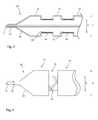
- FIG. 3is a schematic diagram in cross-section of an embodiment of delivery balloon
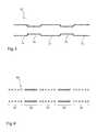
- FIG. 4is a schematic diagram of a portion of another embodiment of delivery balloon in an inflated condition
- FIG. 5is a schematic diagram in cross-section of an embodiment of sleeve for a delivery balloon
- FIG. 6is a schematic diagram in cross-section of another embodiment of sleeve for a delivery balloon
- FIGS. 7 and 8show a device deployment process using the embodiment of delivery system of FIG. 1 ;
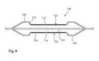
- FIG. 9is a schematic diagram in cross-section of another embodiment of a delivery balloon for administering a medicament to a patient.
- FIG. 1this shows in cross-section an embodiment of delivery apparatus 10 , upon which is mounted an implantable medical device 12 .
- the delivery apparatus 10includes a catheter unit 14 , which in this embodiment is formed of a single catheter having at least one lumen 16 therein which is fluidically coupled to an outlet port 18 .
- the catheter unit 14may also include, usefully, at least one second lumen therethrough for the passage of a guide wire (not shown) to enable the delivery device 10 to be deployed over the wire.
- a delivery balloon 20is fitted to the catheter unit 14 and typically includes first and second end portions 22 , 24 coupled to the catheter unit 14 , specifically in fluid tight manner.
- the delivery balloon 20includes conical sections 26 , 28 located between the end portions 22 , 24 and a body portion 30 of the balloon 20 .
- the body portion 30in the depicted embodiment, is substantially cylindrical save for radially constricted zones described in further detail below, and is substantially cylindrical in axial cross-section.
- the balloonincludes a balloon chamber 15 in fluid communication with the port 18 of the catheter unit 14 so as to inflatable and deflatable by fluid fed through the catheter unit 14 .
- the body portion 30includes non-constricted zones 32 which are able to expand radially outwardly on inflation of the delivery balloon 20 to a first inflated diameter D.
- the body member 30also includes constrained sections 34 , which are constrained by constraining elements described in further detail below. As will be apparent from FIG. 1 , the constrained zones 34 are able to extend radially to a second diameter d less that the first inflated diameter D of the unconstrained sections 32 . As a result, the constrained sections 34 create annular recesses in the delivery balloon 20 , for supporting the medical device 12 .
- the constrained sections 34are spaced from one another with non-constrained zones interposed between adjacent constrained sections 34 .
- the constrained sections 34are, in this example, equally spaced from one another, although it is envisaged that in other embodiments the spacing of the constrained sections 34 may be different, for example may vary along the length of the delivery balloon 20 , in dependence upon the nature of the medical device 12 carried on the delivery balloon 20 , on the desired spacing of elements of the delivery device in the patient and so on.
- the constrained sections 34may have similar dimensions but in other embodiments may have different dimensions, for example lengths and/or expanded diameters.
- the medical device 12includes a plurality of individual stent rings 36 , 38 and 40 which are separate from one another.
- Each stent ring 36 - 40may be made from a conventional stent structure, for example to have an undulating, zigzag or other shapes and each may be formed by a single such stent element or by a plurality of such annular stent elements coupled to on another.
- the stent ringscould be a braided structure.
- Medical devices 12 of such a naturethat is formed of a plurality of separate elements, can be particularly useful in the treatment of delicate vessels which require opening or recanalization and where a conventional unitary stent structure would impose undesired straightening forces on the vessel.
- a medical device formed of separate unitswill not impart any significant straightening force on the vessel and will therefore be better able to conform to any curvature in the vessel.
- the skilled personwill appreciate, though, that a medical device formed of a plurality of separate stent elements exhibits challenges in the deployment of the medical device, for instance requiring complex delivery assemblies or multiple delivery stages.
- the medical device 10can also be deployed in a single medical procedure.
- FIG. 2shows another example of use of the device 10 of FIG. 1 , in this case for the delivery of a medical device 50 formed of a plurality of stent rings 52 - 56 which in this example are connected to one another by connecting elements 58 .
- the connecting elements 58need only be loose connectors, for instance threads or weak tie bars.
- the connecting elements 58can usefully lie over the non-constrained zones 32 of the body portion 30 of the delivery balloon 20 , although in other embodiments the unconstrained zones 32 may be provided with channels or recesses for accommodating the connecting elements 58 .
- a medical device having weak connecting elementscan be particularly advantageous for deployment in weak vessels for the reasons given above.
- the delivery device 10 shown hereincan be used to deliver any of a variety of medical devices including stents, stent grafts and other implantable medical devices.
- the size, number and disposition of the constrained zones 34will vary in dependence upon the nature of the medical device to be carried and delivered by the delivery assembly 10 . Specific designs could be readily devised by the person skilled in the art from the teachings herein.
- FIG. 3shows in schematic form and in longitudinal cross-section one embodiment of delivery balloon 20 . It will be appreciated that FIG. 3 depicts only a part of the balloon 20 .
- the balloon 20is formed from one or more layers of flexible material, which may be of any of the materials commonly used for medical balloons.
- the balloonmay be made of conformable or non-conformable material, that is material which does or does not stretch when inflated to operating pressures.
- Embedded within the wall of the balloon 20are a plurality of bands of, in this example, woven, knitted or braided material 60 , having an annular form and a substantially consistent expanded diameter d.
- the bands 60preferably do not stretch when the balloon is inflated to operating pressures, or exhibit only minimal stretch compared to the non-constrained parts of the body portion of the balloon.
- the bands of constraining material 60can usefully be embedded within the wall of the delivery balloon during the fabrication of the balloon 20 .
- the balloon 20may be made from a raw tubing which is heated and inflated in a forming mold, in which the annular bands of constraining material 60 have been disposed.
- the moldwould typically have an inner mold surface consistent with the shape of the formed balloon 20 shown in FIGS. 1 to 3 .
- the raw tubingis heated to an extent sufficient to cause at least partial softening or reflow of the material forming the balloon, such that this material can flow around and into the bands of constraining material, thereby effectively embedding the constraining material into the balloon wall.
- the balloon wallmay be formed as a single layer structure but in other embodiments may be formed from a plurality of different layers with an outer layer or layers having a lower softening or melting temperature compared to an inner layer or layers.
- the person skilled in the artwill appreciate that it is not necessary for the entirety of the bands of constraining material to be embedded within the balloon wall and that in some cases at least part of the material of the bands may extend beyond the outer surface of the balloon wall, although this is not preferred.
- the structurecan be deflated and eventually removed from the mold when sufficiently cooled.
- the structurewill then be unitary.
- FIG. 3is purely exemplary. The person skilled in the art will appreciate that it is not necessary to have right angles in the various wall sections of the balloon 20 and that in practice these are likely to be much less pronounced and typically rounded.
- the structure taught hereinprovides a device which avoids the need for protrusions, ribs or the like, which can add bulk to the balloon and can also limit the radial compressibility of the balloon for deployment purposes.
- the use of woven, knitted or braided thread in the bands 60provides a structure which retains high levels of flexibility, enabling the balloon 20 to be wrapped and folded for delivery purposes, exhibiting behavioural characteristics in this regard which are very similar to conventional medical balloons.
- the bands 60 forming the constraining elementsmay be made of any suitable thread, including suture thread, polyester, ultrahigh molecular weight polyester such as Dyneema and so on.
- the non-constrained portions 32will tend to bulge outwardly radially beyond the constrained zones 34 , to cause recesses at the contained zones 34 useful for holding a medical device or part of a medical device.
- the difference in the inflated diameters of the balloon 20 between the unconstrained zones 32 and the constrained zones 34is about the thickness of the medical device or part of the medical device to be held within the constrained zones 34 .
- this difference in diametersrepresentative of the depth of the recess formed by the constraining elements 60 , should be enough to hold the medical device or portion of medical device securely therewithin. It is not necessary, although it is preferred, for the entire thickness of the medical device or portion of medical device to be housed within the recesses.
- FIG. 4shows another example of medical balloon 20 , in which the constraining elements 60 , formed of woven, knitted or braided bands of material as in the embodiment of FIG. 3 , are disposed outside of the wall of the balloon 20 , rather than being embedded therewithin. It is preferred that the constraining elements 60 are fixed to the balloon wall 20 , which may be by bonding, welding or even partial melting of one or both of the balloon wall and constraining element to cause these to fuse to one another.
- FIGS. 5 and 6show two different embodiments of sleeve structures which may be used in place of the constraining elements shown in FIGS. 3 and 4 , that is of individual annular bands of constraining material.
- FIG. 5depicts in longitudinal cross-section a constraining sleeve 70 formed, preferably, of woven, knitted or braided threads, of which a variety of materials may be used as explained above in connection with the constraining elements 60 .
- the sleeve 70 shown in FIG. 5includes zones 72 which are woven or braided to a great diameter (i.e. zones of first sleeve diameter) than interleaved zones 74 .
- the zones 72 of greater diameterwould typically be disposed at the unconstrained zones 32 of a balloon 20 , whereas the zones 74 of smaller diameter will be disposed at the constrained zones 34 of the balloon.
- the difference in diameters between the zones 72 and 74 of the sleeve 70will create the recesses and raised areas of the body portion 30 of the delivery balloon 20 .
- the entirety of the body portion 30 of the delivery balloon 20or at least the operative part thereof, will incorporate the strengthening sleeve 70 and that the zones 32 may, on inflation of the balloon, in effect be constrained by the sleeve material at the zones 72 but nevertheless be able to expand to a greater diameter than at the zones 74 .
- Provision of a sleeve 70has the advantage of simple manufacture of the balloon 20 and also provides strengthening of the balloon 20 , allowing the balloon 20 be inflated to greater pressures with lower or little risk of balloon burst.
- the sleeve 70could also extend through the conical portions 26 , 28 of the balloon and also to the necks 22 , 24 , providing strengthening along the entire the length of the balloon 20 .
- the material used for the sleeve 70is non-elastic, although it is not excluded that the material could be of elastic form.
- FIG. 6shows another embodiment of sleeve 80 , which is formed of first zones 82 interleaved with second zones 84 .
- the sleeve 80has, in this embodiment, a generally uniform diameter along its length, in contrast with the sleeve 70 , which has a varying diameter between the zones 72 and 74 .
- the sleeve 80has a structure whereby the zones 84 will expand less during inflation of a balloon incorporating the sleeve 80 . This can be achieved in several different ways. In one example, the zones 82 may have a looser weave than the zones 84 .
- the braid angle in the zones 82may be shallower than the braid angle in the zones 84 , that is the zones 82 will be braided at an angle able to expand radially outwardly to a greater extent than the zones 84 .
- the sleeve 80may be made of different materials, with the zones 84 made of a material having lower elasticity than the material used to form the zones 82 . This can be achieved by varying the material used during the weaving or knitting process or by forming separate annular bands and coupling these to one another, for example by suturing or the like.
- the sleeve 80When embedded in the wall of a balloon 20 (or disposed on the balloon 20 ), the sleeve 80 will cause the balloon 20 to expand differentially and in particular to expand less at the zones 84 , thereby creating annular recesses in the surface of the balloon for accommodating a medical device or part thereof.
- FIGS. 7 and 8show the embodiment of medical balloon 20 of FIG. 1 in the process of deployment of the medical device 12 into a patient.
- FIG. 7shows the deployment device 10 in position in vessel 90 at the target site to be treated.
- the deployment balloon 20is shown in an inflated condition, achieved by feeding inflation fluid through the lumen 16 of the catheter 14 , which exits through the outlet 18 shown in FIGS. 1 and 2 .
- Any suitable inflation fluidcan be used, including for instance saline solution, contrast media and so on.
- the medical device 12On inflation of the balloon 20 , the medical device 12 , in this example the stent rings 36 - 40 which previously have been crimped onto the folded and wrapped balloon 20 , are radially expanded to come into contact with the wall of the vessel 90 .
- the portions 32 of the balloon 20will expand radially outwardly to a greater extent than the constrained portions 34 , thereby holding the stent elements 36 - 40 in position.
- the constraining elements 60will maintain the recesses for holding the stent elements 36 - 40 .
- the balloon 20can be deflated, whereupon the entirety of the balloon will collapse radially inwardly without leaving any protrusions or ribs which could snag against the deployed medical device, allowing the balloon 20 to be withdrawn, with the catheter 14 , from the patient's vessel.
- the stent elementswill be deployed in the correct locations, at the correct spacing and with minimal risk of slippage of the medical device during the deployment process.
- FIG. 9shows another embodiment of balloon assembly 100 having a constraining sleeve 102 extending along the body portion, leaving first and second unconstrained end zones 104 , 106 in the body portion.
- the balloon wall 110includes at least one hole or port 112 therein providing passage from the balloon chamber 120 .
- the hole or holes 112are sized to allow the balloon 100 to be inflated and allow for seepage of inflation fluid from the chamber into the space 122 provided by the constraining sleeve 102 between the balloon 100 and the vessel wall.
- the agentWhen the balloon is filled with a bioactive agent, a medicament for example, the agent will be administered into the vessel between the in the space 122 and confined by the unconstrained zones 104 , 106 , thereby to provide targeted drug delivery into the patient.
- the bioactive agentcan be any of the known agents.
- the structure shown in FIG. 9has the advantage of providing a reliable contained vessel zone with a structure of delivery device which can be contracted, by folding and wrapping onto the delivery catheter, into a narrow diameter. It is to be understood that a balloon of this type could be produced with a plurality of drug delivery zones 122 , by having a plurality of constraining sleeves 102 along the body portion, similar to the arrangement shown in FIG. 1 for instance.
- the constraining sleeve or sleeves disclosed hereinmay usefully be made of materials having a fibre density of Dtex 55 . In embodiments having fibres of different densities, these could vary around Dtex 55 .
- constraining elements 60could be made or include radiopaque material.
Landscapes
- Health & Medical Sciences (AREA)
- Engineering & Computer Science (AREA)
- Biomedical Technology (AREA)
- Heart & Thoracic Surgery (AREA)
- Life Sciences & Earth Sciences (AREA)
- Veterinary Medicine (AREA)
- Animal Behavior & Ethology (AREA)
- Public Health (AREA)
- General Health & Medical Sciences (AREA)
- Cardiology (AREA)
- Oral & Maxillofacial Surgery (AREA)
- Vascular Medicine (AREA)
- Transplantation (AREA)
- Child & Adolescent Psychology (AREA)
- Biophysics (AREA)
- Pulmonology (AREA)
- Anesthesiology (AREA)
- Hematology (AREA)
- Media Introduction/Drainage Providing Device (AREA)
Abstract
Description
Claims (22)
Applications Claiming Priority (2)
| Application Number | Priority Date | Filing Date | Title |
|---|---|---|---|
| GB1406404.2 | 2014-04-09 | ||
| GB1406404.2AGB2525005B (en) | 2014-04-09 | 2014-04-09 | Delivery system for implantable medical device |
Publications (2)
| Publication Number | Publication Date |
|---|---|
| US20150290007A1 US20150290007A1 (en) | 2015-10-15 |
| US10463519B2true US10463519B2 (en) | 2019-11-05 |
Family
ID=50777080
Family Applications (1)
| Application Number | Title | Priority Date | Filing Date |
|---|---|---|---|
| US14/681,271Active2036-02-26US10463519B2 (en) | 2014-04-09 | 2015-04-08 | Delivery system for implantable medical device |
Country Status (2)
| Country | Link |
|---|---|
| US (1) | US10463519B2 (en) |
| GB (1) | GB2525005B (en) |
Cited By (3)
| Publication number | Priority date | Publication date | Assignee | Title |
|---|---|---|---|---|
| US11779481B2 (en) | 2016-05-25 | 2023-10-10 | W. L. Gore & Associates, Inc. | Controlled endoprosthesis balloon expansion |
| US11857444B2 (en) | 2014-11-26 | 2024-01-02 | W. L. Gore & Associates, Inc. | Balloon expandable endoprosthesis |
| US11865020B2 (en) | 2008-01-11 | 2024-01-09 | W. L. Gore & Associates, Inc. | Stent having adjacent elements connected by flexible webs |
Families Citing this family (18)
| Publication number | Priority date | Publication date | Assignee | Title |
|---|---|---|---|---|
| US9962528B2 (en)* | 2015-07-22 | 2018-05-08 | Cook Medical Technologies Llc | Variable diameter woven medical tube textiles and method of making same |
| US20180008444A1 (en)* | 2016-07-11 | 2018-01-11 | Cook Medical Technologies Llc | Multi-stage balloon catheter, and method of operating same in a curved passageway |
| US10653523B2 (en) | 2017-01-19 | 2020-05-19 | 4C Medical Technologies, Inc. | Systems, methods and devices for delivery systems, methods and devices for implanting prosthetic heart valves |
| US10433993B2 (en) | 2017-01-20 | 2019-10-08 | Medtronic Vascular, Inc. | Valve prosthesis having a radially-expandable sleeve integrated thereon for delivery and prevention of paravalvular leakage |
| US10561495B2 (en) | 2017-01-24 | 2020-02-18 | 4C Medical Technologies, Inc. | Systems, methods and devices for two-step delivery and implantation of prosthetic heart valve |
| US12029647B2 (en) | 2017-03-07 | 2024-07-09 | 4C Medical Technologies, Inc. | Systems, methods and devices for prosthetic heart valve with single valve leaflet |
| US12036113B2 (en) | 2017-06-14 | 2024-07-16 | 4C Medical Technologies, Inc. | Delivery of heart chamber prosthetic valve implant |
| US20200139155A1 (en)* | 2017-12-15 | 2020-05-07 | Braxx Biotech Co., Ltd | Catheter apparatus and brachytherapy system |
| US11857441B2 (en) | 2018-09-04 | 2024-01-02 | 4C Medical Technologies, Inc. | Stent loading device |
| US11351028B2 (en)* | 2018-09-04 | 2022-06-07 | 4C Medical Technologies, Inc. | Stent loading device with fluid reservoir |
| US11452628B2 (en) | 2019-04-15 | 2022-09-27 | 4C Medical Technologies, Inc. | Loading systems for collapsible prosthetic heart valve devices and methods thereof |
| CN112089951A (en)* | 2019-06-18 | 2020-12-18 | 微创神通医疗科技(上海)有限公司 | Medical balloon, balloon catheter and medical device |
| US11931253B2 (en) | 2020-01-31 | 2024-03-19 | 4C Medical Technologies, Inc. | Prosthetic heart valve delivery system: ball-slide attachment |
| US12133797B2 (en) | 2020-01-31 | 2024-11-05 | 4C Medical Technologies, Inc. | Prosthetic heart valve delivery system: paddle attachment feature |
| US12053375B2 (en) | 2020-03-05 | 2024-08-06 | 4C Medical Technologies, Inc. | Prosthetic mitral valve with improved atrial and/or annular apposition and paravalvular leakage mitigation |
| US11992403B2 (en) | 2020-03-06 | 2024-05-28 | 4C Medical Technologies, Inc. | Devices, systems and methods for improving recapture of prosthetic heart valve device with stent frame having valve support with inwardly stent cells |
| CN112827057B (en)* | 2020-12-31 | 2023-04-14 | 先健科技(深圳)有限公司 | balloon catheter |
| WO2023040321A1 (en)* | 2021-09-18 | 2023-03-23 | 上海纽脉医疗科技股份有限公司 | Prosthetic valve delivery system, blocking pieces and interventional medical apparatus |
Citations (37)
| Publication number | Priority date | Publication date | Assignee | Title |
|---|---|---|---|---|
| US5409495A (en)* | 1993-08-24 | 1995-04-25 | Advanced Cardiovascular Systems, Inc. | Apparatus for uniformly implanting a stent |
| US5484411A (en)* | 1994-01-14 | 1996-01-16 | Cordis Corporation | Spiral shaped perfusion balloon and method of use and manufacture |
| EP0714640A1 (en) | 1994-11-28 | 1996-06-05 | Advanced Cardiovascular Systems, Inc. | System and method for delivering multiple stents |
| US5620457A (en)* | 1994-11-23 | 1997-04-15 | Medinol Ltd. | Catheter balloon |
| WO1997021400A1 (en) | 1995-12-11 | 1997-06-19 | Guerin Yves Francois | Device for implanting a vascular endoprosthesis |
| EP0834293A1 (en) | 1996-10-01 | 1998-04-08 | Cordis Europa N.V. | Balloon catheter for placing a stent |
| US5836965A (en) | 1994-10-19 | 1998-11-17 | Jendersee; Brad | Stent delivery and deployment method |
| US5935135A (en)* | 1995-09-29 | 1999-08-10 | United States Surgical Corporation | Balloon delivery system for deploying stents |
| US5976181A (en) | 1997-09-22 | 1999-11-02 | Ave Connaught | Balloon mounted stent and method therefor |
| US6010480A (en) | 1993-08-23 | 2000-01-04 | Boston Scientific Corporation | Balloon catheter |
| US6022359A (en)* | 1999-01-13 | 2000-02-08 | Frantzen; John J. | Stent delivery system featuring a flexible balloon |
| US6027510A (en) | 1997-12-08 | 2000-02-22 | Inflow Dynamics Inc. | Stent delivery system |
| US6048350A (en) | 1999-06-14 | 2000-04-11 | Scimed Life Systems, Inc. | Segmented balloon delivery system |
| US6110192A (en) | 1996-09-23 | 2000-08-29 | Boston Scientific Corporation | Catheter balloon having raised radial segments |
| US6129706A (en) | 1998-12-10 | 2000-10-10 | Janacek; Jaroslav | Corrugated catheter balloon |
| EP1132059A1 (en) | 2000-03-07 | 2001-09-12 | Cordis Corporation | Balloon catheter with balloon shoulders |
| US6306162B1 (en) | 1999-12-15 | 2001-10-23 | Advanced Cardiovascular Systems, Inc. | Stent delivery system utilizing novel balloon for obtaining variable post-deployment stent characteristics |
| US20020120321A1 (en)* | 2001-02-26 | 2002-08-29 | Gunderson Richard C. | Stent retention mechanism |
| US6478807B1 (en) | 2000-06-08 | 2002-11-12 | Advanced Cardiovascular Systems, Inc. | Pre-formed expandable member having grooves |
| US20030028211A1 (en)* | 1994-02-24 | 2003-02-06 | Michael Crocker | Focalized stent implantation |
| US20030032999A1 (en) | 2001-08-07 | 2003-02-13 | Medtronic Ave, Inc. | Balloon stent assembly system and method |
| US20040138731A1 (en) | 2001-02-16 | 2004-07-15 | Johnson Eric G. | Method of balloon catheter stent delivery system with ridges |
| US6764504B2 (en) | 2001-01-04 | 2004-07-20 | Scimed Life Systems, Inc. | Combined shaped balloon and stent protector |
| US20050049608A1 (en) | 2003-06-12 | 2005-03-03 | Aznoian Harold M. | Stent delivery catheter |
| US7004963B2 (en) | 2001-09-14 | 2006-02-28 | Scimed Life Systems, Inc. | Conformable balloons |
| US7056323B2 (en) | 1999-03-31 | 2006-06-06 | Scimed Life Systems, Inc. | Stent security balloon/balloon catheter |
| US20060135980A1 (en)* | 2004-12-20 | 2006-06-22 | Scimed Life Systems, Inc. | Balloon with stepped sections and implements |
| US7083639B2 (en) | 2001-09-26 | 2006-08-01 | Medtronic Vascular, Inc. | Stent delivery catheter with grooved balloon and methods of making same |
| US20080183132A1 (en)* | 2004-10-15 | 2008-07-31 | Futurematrix Interventional, Inc. | Non-compliant medical balloon having braided or knitted reinforcement |
| US20090069878A1 (en)* | 2007-08-27 | 2009-03-12 | Boston Scientific Scimed, Inc. | Bifurcation post-dilatation balloon and methods |
| US7776078B2 (en) | 2003-05-22 | 2010-08-17 | Boston Scientfic Scimed, Inc. | Catheter balloon with improved retention |
| US7963987B2 (en) | 2007-12-28 | 2011-06-21 | Cook Medical Technologies Llc | Sequential implant delivery system |
| US20110152997A1 (en) | 2008-06-05 | 2011-06-23 | Daniel John Kelly | Delivery system for multiple stents |
| WO2011112863A1 (en) | 2010-03-12 | 2011-09-15 | Quatro Vascular Pe Ltd. | Device and method for compartmental vessel treatment |
| US8048028B2 (en) | 2005-02-17 | 2011-11-01 | Boston Scientific Scimed, Inc. | Reinforced medical balloon |
| US8333000B2 (en) | 2006-06-19 | 2012-12-18 | Advanced Cardiovascular Systems, Inc. | Methods for improving stent retention on a balloon catheter |
| US20130116655A1 (en)* | 2011-10-07 | 2013-05-09 | John E. Bacino | Balloon assemblies having controllably variable topographies |
- 2014
- 2014-04-09GBGB1406404.2Apatent/GB2525005B/enactiveActive
- 2015
- 2015-04-08USUS14/681,271patent/US10463519B2/enactiveActive
Patent Citations (40)
| Publication number | Priority date | Publication date | Assignee | Title |
|---|---|---|---|---|
| US6010480A (en) | 1993-08-23 | 2000-01-04 | Boston Scientific Corporation | Balloon catheter |
| US5409495A (en)* | 1993-08-24 | 1995-04-25 | Advanced Cardiovascular Systems, Inc. | Apparatus for uniformly implanting a stent |
| US5484411A (en)* | 1994-01-14 | 1996-01-16 | Cordis Corporation | Spiral shaped perfusion balloon and method of use and manufacture |
| US20030028211A1 (en)* | 1994-02-24 | 2003-02-06 | Michael Crocker | Focalized stent implantation |
| US5836965A (en) | 1994-10-19 | 1998-11-17 | Jendersee; Brad | Stent delivery and deployment method |
| US5620457A (en)* | 1994-11-23 | 1997-04-15 | Medinol Ltd. | Catheter balloon |
| EP0714640A1 (en) | 1994-11-28 | 1996-06-05 | Advanced Cardiovascular Systems, Inc. | System and method for delivering multiple stents |
| US5935135A (en)* | 1995-09-29 | 1999-08-10 | United States Surgical Corporation | Balloon delivery system for deploying stents |
| WO1997021400A1 (en) | 1995-12-11 | 1997-06-19 | Guerin Yves Francois | Device for implanting a vascular endoprosthesis |
| US6110192A (en) | 1996-09-23 | 2000-08-29 | Boston Scientific Corporation | Catheter balloon having raised radial segments |
| EP0834293A1 (en) | 1996-10-01 | 1998-04-08 | Cordis Europa N.V. | Balloon catheter for placing a stent |
| US5976181A (en) | 1997-09-22 | 1999-11-02 | Ave Connaught | Balloon mounted stent and method therefor |
| US6027510A (en) | 1997-12-08 | 2000-02-22 | Inflow Dynamics Inc. | Stent delivery system |
| US6129706A (en) | 1998-12-10 | 2000-10-10 | Janacek; Jaroslav | Corrugated catheter balloon |
| US6022359A (en)* | 1999-01-13 | 2000-02-08 | Frantzen; John J. | Stent delivery system featuring a flexible balloon |
| US7056323B2 (en) | 1999-03-31 | 2006-06-06 | Scimed Life Systems, Inc. | Stent security balloon/balloon catheter |
| US6048350A (en) | 1999-06-14 | 2000-04-11 | Scimed Life Systems, Inc. | Segmented balloon delivery system |
| US6306162B1 (en) | 1999-12-15 | 2001-10-23 | Advanced Cardiovascular Systems, Inc. | Stent delivery system utilizing novel balloon for obtaining variable post-deployment stent characteristics |
| EP1132059A1 (en) | 2000-03-07 | 2001-09-12 | Cordis Corporation | Balloon catheter with balloon shoulders |
| US6478807B1 (en) | 2000-06-08 | 2002-11-12 | Advanced Cardiovascular Systems, Inc. | Pre-formed expandable member having grooves |
| US6764504B2 (en) | 2001-01-04 | 2004-07-20 | Scimed Life Systems, Inc. | Combined shaped balloon and stent protector |
| US20040138731A1 (en) | 2001-02-16 | 2004-07-15 | Johnson Eric G. | Method of balloon catheter stent delivery system with ridges |
| US6942681B2 (en) | 2001-02-16 | 2005-09-13 | Cordis Corporation | Method of balloon catheter stent delivery system with ridges |
| US20020120321A1 (en)* | 2001-02-26 | 2002-08-29 | Gunderson Richard C. | Stent retention mechanism |
| US20030032999A1 (en) | 2001-08-07 | 2003-02-13 | Medtronic Ave, Inc. | Balloon stent assembly system and method |
| US7004963B2 (en) | 2001-09-14 | 2006-02-28 | Scimed Life Systems, Inc. | Conformable balloons |
| US7083639B2 (en) | 2001-09-26 | 2006-08-01 | Medtronic Vascular, Inc. | Stent delivery catheter with grooved balloon and methods of making same |
| US7776078B2 (en) | 2003-05-22 | 2010-08-17 | Boston Scientfic Scimed, Inc. | Catheter balloon with improved retention |
| US20050049608A1 (en) | 2003-06-12 | 2005-03-03 | Aznoian Harold M. | Stent delivery catheter |
| US20080183132A1 (en)* | 2004-10-15 | 2008-07-31 | Futurematrix Interventional, Inc. | Non-compliant medical balloon having braided or knitted reinforcement |
| US20060135980A1 (en)* | 2004-12-20 | 2006-06-22 | Scimed Life Systems, Inc. | Balloon with stepped sections and implements |
| US7879053B2 (en) | 2004-12-20 | 2011-02-01 | Boston Scientific Scimed, Inc. | Balloon with stepped sections and implements |
| US8048028B2 (en) | 2005-02-17 | 2011-11-01 | Boston Scientific Scimed, Inc. | Reinforced medical balloon |
| US8333000B2 (en) | 2006-06-19 | 2012-12-18 | Advanced Cardiovascular Systems, Inc. | Methods for improving stent retention on a balloon catheter |
| US20090069878A1 (en)* | 2007-08-27 | 2009-03-12 | Boston Scientific Scimed, Inc. | Bifurcation post-dilatation balloon and methods |
| US7963987B2 (en) | 2007-12-28 | 2011-06-21 | Cook Medical Technologies Llc | Sequential implant delivery system |
| US20110152997A1 (en) | 2008-06-05 | 2011-06-23 | Daniel John Kelly | Delivery system for multiple stents |
| WO2011112863A1 (en) | 2010-03-12 | 2011-09-15 | Quatro Vascular Pe Ltd. | Device and method for compartmental vessel treatment |
| US20120059401A1 (en)* | 2010-03-12 | 2012-03-08 | Quatro Vascular Pe Ltd. | Device and method for compartmental vessel treatment |
| US20130116655A1 (en)* | 2011-10-07 | 2013-05-09 | John E. Bacino | Balloon assemblies having controllably variable topographies |
Non-Patent Citations (1)
| Title |
|---|
| Great Britain Combined Examination and Search Report from corresponding Great Britain application No. GB1406404.2 dated Nov. 4, 2014 (5 pgs). |
Cited By (6)
| Publication number | Priority date | Publication date | Assignee | Title |
|---|---|---|---|---|
| US11865020B2 (en) | 2008-01-11 | 2024-01-09 | W. L. Gore & Associates, Inc. | Stent having adjacent elements connected by flexible webs |
| US12329667B2 (en) | 2008-01-11 | 2025-06-17 | W. L. Gore & Associates, Inc. | Stent having adjacent elements connected by flexible webs |
| US11857444B2 (en) | 2014-11-26 | 2024-01-02 | W. L. Gore & Associates, Inc. | Balloon expandable endoprosthesis |
| US12226329B2 (en) | 2014-11-26 | 2025-02-18 | W. L. Gore & Associates, Inc. | Balloon expandable endoprosthesis |
| US11779481B2 (en) | 2016-05-25 | 2023-10-10 | W. L. Gore & Associates, Inc. | Controlled endoprosthesis balloon expansion |
| US12427046B2 (en) | 2016-05-25 | 2025-09-30 | W. L. Gore & Associates, Inc. | Controlled endoprosthesis balloon expansion |
Also Published As
| Publication number | Publication date |
|---|---|
| GB2525005B (en) | 2016-03-09 |
| GB2525005A (en) | 2015-10-14 |
| GB201406404D0 (en) | 2014-05-21 |
| US20150290007A1 (en) | 2015-10-15 |
Similar Documents
| Publication | Publication Date | Title |
|---|---|---|
| US10463519B2 (en) | Delivery system for implantable medical device | |
| US12427046B2 (en) | Controlled endoprosthesis balloon expansion | |
| US20250152391A1 (en) | Balloon expandable endoprosthesis | |
| CN101854884A (en) | Stent deployment device and method | |
| US9980833B2 (en) | Uniform expandable and collapsible stent |
Legal Events
| Date | Code | Title | Description |
|---|---|---|---|
| AS | Assignment | Owner name:COOK MEDICAL TECHNOLOGIES LLC, INDIANA Free format text:ASSIGNMENT OF ASSIGNORS INTEREST;ASSIGNOR:WILLIAM COOK EUROPE APS;REEL/FRAME:035425/0932 Effective date:20140401 Owner name:COOK MEDICAL TECHNOLOGIES LLC, INDIANA Free format text:ASSIGNMENT OF ASSIGNORS INTEREST;ASSIGNORS:AGGERHOLM, STEEN;LYSGAARD, THOMAS;REEL/FRAME:035425/0946 Effective date:20140331 | |
| AS | Assignment | Owner name:WILLIAM COOK EUROPE APS, DENMARK Free format text:CORRECTIVE ASSIGNMENT TO CORRECT THE ASSIGNEE NAME PREVIOUSLY RECORDED AT REEL: 035425 FRAME: 0946. ASSIGNOR(S) HEREBY CONFIRMS THE ASSIGNMENT;ASSIGNORS:AGGERHOLM, STEEN;LYSGAARD, THOMAS;REEL/FRAME:035636/0090 Effective date:20140331 | |
| STPP | Information on status: patent application and granting procedure in general | Free format text:NON FINAL ACTION MAILED | |
| STPP | Information on status: patent application and granting procedure in general | Free format text:RESPONSE TO NON-FINAL OFFICE ACTION ENTERED AND FORWARDED TO EXAMINER | |
| STPP | Information on status: patent application and granting procedure in general | Free format text:NOTICE OF ALLOWANCE MAILED -- APPLICATION RECEIVED IN OFFICE OF PUBLICATIONS | |
| STPP | Information on status: patent application and granting procedure in general | Free format text:PUBLICATIONS -- ISSUE FEE PAYMENT VERIFIED | |
| STCF | Information on status: patent grant | Free format text:PATENTED CASE | |
| MAFP | Maintenance fee payment | Free format text:PAYMENT OF MAINTENANCE FEE, 4TH YEAR, LARGE ENTITY (ORIGINAL EVENT CODE: M1551); ENTITY STATUS OF PATENT OWNER: LARGE ENTITY Year of fee payment:4 | |
| AS | Assignment | Owner name:WILMINGTON TRUST, NATIONAL ASSOCIATION, AS COLLATERAL AGENT, DELAWARE Free format text:SECURITY INTEREST;ASSIGNOR:COOK MEDICAL TECHNOLOGIES LLC;REEL/FRAME:066700/0277 Effective date:20240227 |