US10463325B2 - Mobile radiographic apparatus/methods with tomosynthesis capability - Google Patents
Mobile radiographic apparatus/methods with tomosynthesis capabilityDownload PDFInfo
- Publication number
- US10463325B2 US10463325B2US16/003,653US201816003653AUS10463325B2US 10463325 B2US10463325 B2US 10463325B2US 201816003653 AUS201816003653 AUS 201816003653AUS 10463325 B2US10463325 B2US 10463325B2
- Authority
- US
- United States
- Prior art keywords
- ray
- mobile
- subject
- projection
- ray source
- Prior art date
- Legal status (The legal status is an assumption and is not a legal conclusion. Google has not performed a legal analysis and makes no representation as to the accuracy of the status listed.)
- Active, expires
Links
Images


Classifications
- A—HUMAN NECESSITIES
- A61—MEDICAL OR VETERINARY SCIENCE; HYGIENE
- A61B—DIAGNOSIS; SURGERY; IDENTIFICATION
- A61B6/00—Apparatus or devices for radiation diagnosis; Apparatus or devices for radiation diagnosis combined with radiation therapy equipment
- A61B6/44—Constructional features of apparatus for radiation diagnosis
- A61B6/4405—Constructional features of apparatus for radiation diagnosis the apparatus being movable or portable, e.g. handheld or mounted on a trolley
- A—HUMAN NECESSITIES
- A61—MEDICAL OR VETERINARY SCIENCE; HYGIENE
- A61B—DIAGNOSIS; SURGERY; IDENTIFICATION
- A61B6/00—Apparatus or devices for radiation diagnosis; Apparatus or devices for radiation diagnosis combined with radiation therapy equipment
- A61B6/02—Arrangements for diagnosis sequentially in different planes; Stereoscopic radiation diagnosis
- A61B6/025—Tomosynthesis
- A—HUMAN NECESSITIES
- A61—MEDICAL OR VETERINARY SCIENCE; HYGIENE
- A61B—DIAGNOSIS; SURGERY; IDENTIFICATION
- A61B6/00—Apparatus or devices for radiation diagnosis; Apparatus or devices for radiation diagnosis combined with radiation therapy equipment
- A61B6/02—Arrangements for diagnosis sequentially in different planes; Stereoscopic radiation diagnosis
- A61B6/03—Computed tomography [CT]
- A61B6/032—Transmission computed tomography [CT]
- A—HUMAN NECESSITIES
- A61—MEDICAL OR VETERINARY SCIENCE; HYGIENE
- A61B—DIAGNOSIS; SURGERY; IDENTIFICATION
- A61B6/00—Apparatus or devices for radiation diagnosis; Apparatus or devices for radiation diagnosis combined with radiation therapy equipment
- A61B6/40—Arrangements for generating radiation specially adapted for radiation diagnosis
- A61B6/4007—Arrangements for generating radiation specially adapted for radiation diagnosis characterised by using a plurality of source units
- A—HUMAN NECESSITIES
- A61—MEDICAL OR VETERINARY SCIENCE; HYGIENE
- A61B—DIAGNOSIS; SURGERY; IDENTIFICATION
- A61B6/00—Apparatus or devices for radiation diagnosis; Apparatus or devices for radiation diagnosis combined with radiation therapy equipment
- A61B6/40—Arrangements for generating radiation specially adapted for radiation diagnosis
- A61B6/4021—Arrangements for generating radiation specially adapted for radiation diagnosis involving movement of the focal spot
- A61B6/4028—Arrangements for generating radiation specially adapted for radiation diagnosis involving movement of the focal spot resulting in acquisition of views from substantially different positions, e.g. EBCT
- A—HUMAN NECESSITIES
- A61—MEDICAL OR VETERINARY SCIENCE; HYGIENE
- A61B—DIAGNOSIS; SURGERY; IDENTIFICATION
- A61B6/00—Apparatus or devices for radiation diagnosis; Apparatus or devices for radiation diagnosis combined with radiation therapy equipment
- A61B6/42—Arrangements for detecting radiation specially adapted for radiation diagnosis
- A61B6/4283—Arrangements for detecting radiation specially adapted for radiation diagnosis characterised by a detector unit being housed in a cassette
- A—HUMAN NECESSITIES
- A61—MEDICAL OR VETERINARY SCIENCE; HYGIENE
- A61B—DIAGNOSIS; SURGERY; IDENTIFICATION
- A61B6/00—Apparatus or devices for radiation diagnosis; Apparatus or devices for radiation diagnosis combined with radiation therapy equipment
- A61B6/46—Arrangements for interfacing with the operator or the patient
- A61B6/461—Displaying means of special interest
- A61B6/462—Displaying means of special interest characterised by constructional features of the display
- A—HUMAN NECESSITIES
- A61—MEDICAL OR VETERINARY SCIENCE; HYGIENE
- A61B—DIAGNOSIS; SURGERY; IDENTIFICATION
- A61B6/00—Apparatus or devices for radiation diagnosis; Apparatus or devices for radiation diagnosis combined with radiation therapy equipment
- A61B6/46—Arrangements for interfacing with the operator or the patient
- A61B6/461—Displaying means of special interest
- A61B6/464—Displaying means of special interest involving a plurality of displays
Definitions
- the inventionrelates generally to the field of medical imaging, and in particular to mobile radiographic imaging apparatus. More specifically, the invention relates to a mobile radiography apparatus having additional tomosynthesis capability.
- Tomographyalso referred to as x-ray computed tomography or computed tomography (CT)
- CTcomputed tomography
- Digital image processingis used to generate a three-dimensional image of the inside of an object from a series/collection of two-dimensional x-ray images taken around a single axis of rotation.
- a source/detectormakes a complete 360-degree rotation about the subject obtaining a complete volume of data from which images may be reconstructed.
- the volume of data produced by the CT systemis manipulated to generate body structures.
- the imagescan be generated in the axial or transverse plane (e.g., perpendicular to the long axis of the body) or reformatted in various planes or a volumetric three-dimensional representation.
- Tomosynthesiscombines digital image capture and processing with source/detector motion used in tomography. While there are some similarities to CT, some view it as a separate technique. As noted above, in CT, the source/detector makes a complete 360-degree rotation about the subject obtaining a complete set of data from which images may be reconstructed. In digital tomosynthesis, a small rotation angle (e.g., 30 degrees) with a small number of discrete slices/exposures (e.g., 10) are used. This incomplete set of data is digitally processed to yield images similar to tomography with a limited depth of field.
- a small rotation anglee.g. 30 degrees
- discrete slices/exposurese.g. 10
- An aspect of this applicationis to advance the art of mobile radiography.
- Another aspect of the applicationis to provide methods and/or apparatus by which mobile radiography carts can additionally include tomosynthesis capabilities.
- Another aspect of the applicationis to provide methods and/or apparatus by which mobile radiography carts can be modified to operate in a first mode to obtain at least one general radiography projection image of an object using a first type central x-ray source, and to operate in a second mode to obtain a plurality of x-ray tomosynthesis projection images of an object using a plurality of second type distributed x-ray sources.
- Another aspect of the applicationis to provide methods and/or apparatus by which mobile radiography carts can include an X-ray source assembly including a first central x-ray high power source and a second plurality of distributed x-ray lower power sources disposed in a prescribed spatial relationship.
- Another aspect of the applicationis to provide methods and/or apparatus by which mobile radiography carts can include an X-ray source assembly including a plurality of distributed x-ray power sources where at least one central source of the distributed x-ray power sources has full (e.g., standard) X-ray power.
- the present inventioncan provide a mobile radiography apparatus that can include a moveable transport frame, an adjustable support structure coupled to the moveable transport frame, an x-ray source assembly mounted to the adjustable support structure configured to direct x-ray radiation towards a subject from one or a plurality of different source positions, where the x-ray source assembly includes a first x-ray power source and a second plurality of distributed x-ray sources disposed in a prescribed spatial relationship, control circuitry at the mobile x-ray radiography apparatus and coupled to the x-ray source assembly, the control circuitry configured to receive projection image data sets for reconstruction of tomosynthesis images.
- the present inventioncan provide a method for operating a portable x-ray radiography apparatus, the method can include one or more processors performing processes for operating in a first mode, where operating in the first mode includes obtaining at least one general radiography projection image of an object using a first type central x-ray source, and generating a reconstruction of the object using the at least one general radiography projection image, and operating in a second mode, where operating in the second mode includes obtaining a plurality of x-ray tomosynthesis projection images of an object using a plurality of second type distributed x-ray sources disposed in a prescribed spatial relationship, and generating a three-dimensional reconstruction of the object using the x-ray projection images.
- FIG. 1is a diagram that shows a perspective view of a mobile radiography unit with a second display according to one embodiment of the application.
- FIG. 2is a diagram that shows a perspective view of a mobile radiography unit of FIG. 1 positioned for travel.
- FIG. 3is a diagram that shows an exemplary embodiment of a display/monitor as a second display mounted to a boom assembly of a mobile radiography unit according to the application.
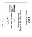
- FIG. 4is a diagram that illustrates an embodiment of a single sign on screen according to the application.
- FIGS. 5-8are diagrams that illustrate exemplary functions implemented at an embodiment of a second display of a mobile x-ray imaging apparatus.
- FIG. 9is a diagram that shows a perspective view of a mobile radiography unit that can provide a tomosynthesis capability according to embodiments of the application.
- FIG. 10is a diagram that shows exemplary mobile radiographic imaging systems including an x-ray source assembly embodiment that can include first and second radiographic x-ray sources according to the application.
- FIG. 11is a diagram that shows exemplary mobile radiographic imaging systems including an x-ray source assembly embodiment that can include first and second radiographic x-ray sources according to the application.
- FIG. 12is a flow chart that shows an exemplary method of operating exemplary mobile radiographic imaging systems for acquiring projections images and generating the reconstruction of three-dimensional tomosynthesis images.
- tomosynthesisprovides improved depiction of fine details not visible in normal radiographs due to overlying structures.
- Such exemplary benefits of tomosynthesisprovide the impetus to develop mobile tomosynthesis systems that can be utilized in the intensive care unit, emergency department, and operating rooms where moving patient is either impracticable or ill advised due to the risk of doing further damage to the patient.
- FIG. 1is a diagram that shows a perspective view of a mobile radiography unit that can use portable radiographic detectors or flat panel detectors according to embodiments of the application.
- the exemplary mobile x-ray or radiographic apparatus of FIG. 1can be employed for digital radiography (DR) and/or tomosynthesis.
- a mobile radiography apparatus 100can include a moveable transport frame 120 that includes a first display 110 and an optional second display 110 ′ to display relevant information such as obtained images and related data.
- the second display 110 ′can be pivotable mounted at the x-ray source 140 to be viewable/touchable from a 360 degree area.
- the displays 110 , 110 ′can implement or control (e.g., touch screens) functions such as generating, storing, transmitting, modifying, and printing of an obtained image(s) and can include an integral or separate control panel (not shown) to assist in implementing functions such as generating, storing, transmitting, modifying, and printing of an obtained image(s).
- controle.g., touch screens
- functionssuch as generating, storing, transmitting, modifying, and printing of an obtained image(s)
- an integral or separate control panelnot shown
- the mobile radiographic apparatus 100can have one or more wheels 115 and one or more handle grips 125 , typically provided at waist-level, arm-level, or hand-level, that help to guide the mobile radiographic apparatus 100 to its intended location.
- a self-contained battery packe.g., rechargeable
- the self-contained battery packcan provide for motorized transport.
- the mobile radiographic apparatus 100can include an area/holder for holding/storing one or more digital radiographic (DR) detectors or computed radiography cassettes.
- the area/holdercan be storage area 130 (e.g., disposed on the frame 120 ) configured to removably retain at least one digital radiography (DR) detector.
- the storage area 130can be configured to hold a plurality of detectors and can also be configured to hold one size or multiple sizes of DR detectors and/or batteries therefore.
- a support column 135that supports an x-ray source 140 , also called an x-ray tube, tube head, or generator that can be mounted to the support member 135 .
- the support membere.g., column 135
- the support membercan include a second section that extends outward a fixed/variable distance from a first section where the second section is configured to ride vertically up and down the first section to the desired height for obtaining the image.
- the support columnis rotatably attached to the moveable frame 120 .
- the tube head or x-ray source 140can be rotatably coupled to the support column 135 .
- an articulated member of the support column that bends at a joint mechanismcan allow movement of the x-ray source 140 over a range of vertical and horizontal positions.
- Height settings for the x-ray source 140can range from low height for imaging feet and lower extremities to shoulder height and above for imaging the upper body portions of patients in various positions.
- the support member 135 and x-ray source 140can be arranged close to frame 120 .
- the second display 110 ′can be in a viewable position (e.g., operable) during transport of the mobile radiographic apparatus 100 .
- the support member 135 and x-ray source 140can be extended from the frame 120 for proper positioning (e.g., by the operator, a user, or x-ray technician) and the second display 110 ′ moved to viewable position such as shown in FIG. 1 .
- FIG. 3is a diagram that shows an exemplary embodiment of a display/monitor as a second display mounted to a boom assembly of a mobile radiography unit according to the application.
- the second display 110 ′can be mounted to a collimator 345 of an x-ray source 340 of a support member 135 of a mobile radiography unit.
- the collimator 345can be rotatably mounted to the x-ray source 340 so that the collimator 345 (e.g., second display 110 ′) can swivel at least 90 degrees, at least 180 degrees or 360 degrees plus.
- the second display 110 ′is coupled to a plurality of handles for ease of positioning.
- the second display 110 ′can be mounted to (e.g., rotatably) an x-ray source 340 above a collimator 345 of a boom assembly of a mobile radiography unit.
- FIG. 4is a diagram that illustrates an embodiment of a sign on screen according to the application.
- a sign on screen 410can be displayed to provide instructions to a user. As shown in FIG.
- the single sign on screen 410can provide instructions for sign on sign on and activate the mobile x-ray system 100 such as “LOGIN: Please scan your badge or type User Name and Password at the main screen.”
- a pass key or ID badgecan include but are not intended to be limited to a card reader such as a smart card, a magnetic stripe card, bar code data, or a proximity reader compatible with access technologies such as RFID, bluetooth, wireless communication device, a proximity card, a wireless smart card, a wiegand card, a magnetic reader device/card, an optical reader device/card, an infrared reader device/card, or biometric data such as fingerprints, eye scan or the like.
- the first display 110 and the second display 110 ′can provide information such as but not limited to: (i) general information such as date, time, environment conditions, and the like; (ii) unit information such as model serial number, operating instructions, warning information, and the like; (iii) patient data, such as patient name, room number, age, blood type, and the like; (iv) indicators such as but not limited to cart power/battery indicators, detector status (e.g., on/off), wireless signal strength/connectivity, grid alignment aides, cart diagnostics and/or (v) imaging/procedure information, such as the exam type, exposure information, and the like.
- general informationsuch as date, time, environment conditions, and the like
- unit informationsuch as model serial number, operating instructions, warning information, and the like
- patient datasuch as patient name, room number, age, blood type, and the like
- indicatorssuch as but not limited to cart power/battery indicators, detector status (e.g., on/off), wireless signal strength/connectivity, grid alignment
- the first display 110 and the second display 110 ′can provide capabilities/functionality to the mobile x-ray imaging apparatus 100 such as but not limited to: (i) view and/or change x-ray exposure parameters, tube/generator/technique settings; (ii) view and/or change image information, such as a list of views (e.g., body part & projection) to perform for the patient, relevant information about those views, the ability to select a view to perform, and an x-ray image of an acquired view; (iii) display and/or change patient information, such as: Patient Name, Room number, Patient ID, date of birth (e.g., to confirm that the correct patient); (iv) display and/or change a Patient Worklist, such as a list of exams to perform and allow the user to select an exam.
- view and/or change image informationsuch as a list of views (e.g., body part & projection) to perform for the patient, relevant information about those views, the ability to select a view to perform, and an x-ray
- such a patient worklistcan be automatically updated (e.g., synchronized to a master/hospital/doctor worklist) using a wired or wireless network/connection.
- the mobile x-ray imaging apparatus 100can highlight/indicate new exams (e.g., on the second display 110 ′) upon receipt of the scheduled examination.); (v) display generator/source current values and controls to change those values, such as: kVp, mA, mAs, Time.
- the mobile x-ray system 100can include a collision avoidance system with alerts (e.g., audible, visual), and automatic maneuvering to avoid contact in the examining room (e.g., by stopping or course modification).
- alertse.g., audible, visual
- automatic maneuveringto avoid contact in the examining room (e.g., by stopping or course modification).
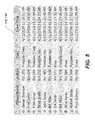
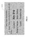
- FIGS. 5-8are diagrams that illustrate exemplary non-limiting representative functions illustrated on an embodiment of a first display and/or a second display of a mobile x-ray imaging apparatus.
- FIG. 5an example of a work list is shown on a monitor of the second display 110 ′.
- FIG. 6an example of a new examination/procedure information/requirement for that technician and/or patient is shown on a monitor of the second display 110 ′.
- an example of x-ray source controlsis shown on a monitor of the second display 110 ′.
- FIG. 8an example of newly acquired image and patient information is shown on a monitor of the second display 110 ′.
- the mobile radiographic imaging apparatuscan be operated/controlled by programmed control logic in the first or second displays.
- the programmed control logiccan include a processor and display, an integrated computer system, or a portable computer and applications to operate thereon.
- FIG. 9is a diagram that shows a perspective view of a mobile radiography unit that can provide a tomosynthesis capability according to embodiments of the application.
- a mobile radiography unitthat can further operate as a tomosynthesis system.
- an embodiment of a mobile radiographic/tomosynthesis system 900is shown that can include a movable transport frame 920 .
- Mounted to the moveable transport frame 920can be a support column that supports an x-ray source assembly 940 .
- a support column 930can include a second section 930 b that extends outward a fixed/variable distance from a first section 930 a , where the second section 930 b is configured to move (e.g., ride vertically) up and down the first section 930 a to the desired height for obtaining the projection images.
- the systemalso includes a digital x-ray detector 950 that is wirelessly (e.g., or wired, tethered) connected to a system controller 915 contained inside the moveable transport frame 920 .
- the system controller 915can implement and/or control the functionality of the mobile radiographic/tomosynthesis system 900 (e.g., functionality provided through a console or control displays 100 , 100 ′).
- the system controller 915can be provided though one or more of a conventional general purpose processor, digital computer, microprocessor, RISC processor, signal processor, CPU, arithmetic logic unit (ALU), video digital signal processor (VDSP) and/or similar computational machines, programmed according to the teachings of the application, as will be apparent to those skilled in the relevant art(s).
- a conventional general purpose processordigital computer, microprocessor, RISC processor, signal processor, CPU, arithmetic logic unit (ALU), video digital signal processor (VDSP) and/or similar computational machines, programmed according to the teachings of the application, as will be apparent to those skilled in the relevant art(s).
- a moveable mounted x-ray sourcecan, in addition, be supplied with a plurality of multiple individually controlled x-rays sources (e.g., a distributed x-ray source array).
- FIG. 9shows an embodiment of a mobile tomosynthesis system where multiple individually controlled x-rays sources comprise distributed x-ray sources (e.g., linearly distributed).
- an x-ray source assemblycan include a plurality of distributed x-ray power sources where at least one central source of the distributed x-ray power sources has full (e.g., standard) x-ray power.
- the central sourcecan have a wide range of kVp settings, such as from 50 kVp to 150 kVp. and high maximum mA output, such as from 10 mA to 400 mA, in order to accommodate many different exam types for general radiography.
- the distributed sourcescan be arrayed in a prescribed spatial relationship.
- the distributed sourcescan be a lower power x-ray sources, which means a narrow range of kVp settings, such as from 60 kVp to 120 kVp. and lower maximum mA output, such as from 1 mA to 100 mA.
- a mobile radiographic/tomosynthesis system 900can include one or more, and preferably all of the capabilities of the mobile radiographic system 100 shown in FIG.
- the x-ray source assembly 940can use collimator(s) to form beams that are directed towards the detector 950 and/or patient P.
- the x-ray source assembly 940may also include positioning, such as motors, which allow for directing the beam towards the detector 950 and/or patient P.
- the moveable transport frame 920can include a first display 910 , which can control at least the x-ray source assembly 940 . Further, the system controller 915 can coordinate operations of the x-ray source assembly 940 , detector 950 , and moveable transport frame 920 (e.g., via operator actions using the first display 910 ).
- the system controller 915can control operations of the x-ray source assembly, which may include the collimator, positioning devices and triggering of image acquisition by emission of x-rays from the sources. For example, the system controller 915 can control x-ray emission for CT imaging procedures and/or for general radiography imaging procedures. The system controller 915 also can control operations of the detector 950 , which may include triggering of the image acquisition and transmission of the acquired images back to the controller. In addition, the system controller 915 can control the movement of the transport frame 920 .
- FIG. 10is a diagram that shows exemplary mobile radiographic imaging systems including an x-ray source assembly that can include first and second (e.g., multiple) radiographic x-ray sources.
- an x-ray source assembly 1040 of a mobile radiographic imaging systemcan include a first radiographic x-ray source and collimator, and a second x-ray source comprising a distributed sources (e.g., rectangle) that can be individually adjusted (e.g., collimated) and either permanently attached or attached (e.g., detachable) when needed.
- the first radiographic x-ray sourcecan be a central one of the distributed sources.
- the first radiographic x-ray sourceis positioned at a center of the second array of distributed sources.
- the first radiographic x-ray sourcecan be a mobile/portable x-ray source/tube and be a different type of x-ray source from the second distributed array of lower power carbon-nanotube x-ray sources.
- FIG. 11is a diagram that shows exemplary mobile radiographic imaging systems including an x-ray source assembly that can include first and second (e.g., multiple) radiographic x-ray sources.
- an x-ray source assembly 1140 of a mobile radiographic imaging systemcan include a directed first radiographic x-ray source and a directed second x-ray source comprising a distributed source attachment (e.g., linear) that can be either permanently attached or attached (detachable) when needed.
- the first radiographic x-ray sourcecan be positioned at a center of the array of distributed sources.
- the first radiographic x-ray sourcecan be a central one of the distributed sources.
- the plurality of distributed x-ray sourcescan be mounted along a support.
- the plurality of distributed x-ray sourcescan have a prescribed spatial relationship, where the prescribed spatial relationship is one or more linear tracks, 2D tracks, curves, polygons, rectangles or 3D paths.
- collimated distributed sourcescan be on a curved support to maintain a single distance from a corresponding point on a detector.
- Exemplary distributed source attachmentcan have a first position for use and a second position for storage (e.g., folded) when not used.
- FIG. 12a flow chart that shows an exemplary method of acquiring projections images and generating the reconstruction of three-dimensional tomosynthesis images, will now be described.
- the method for acquiring projections images and generating the reconstruction of three-dimensional tomosynthesis imageswill be described using embodiments of mobile radiography apparatus shown in FIGS. 9-12 and can be applied to mobile x-ray systems/carts shown in FIGS. 1 and 9-12 ; however, the method of FIG. 12 is not intended to be limited thereby.
- the detector and x-ray source assemblycan be positioned (operation block 1210 ).
- the x-ray sourcecan be moved to its initial position and the detector can be positioned such that the patient P is interposed between the detector and x-ray source.
- the initial x-ray source assembly positioncan be set by the location of the transport frame and the support column.
- the height, extent and rotation positioning of the support column's first section 930 a and the second section 930can be used to position the x-ray source assembly to the initial desired location above the patient.
- a series of projections imagecan be acquired at different x-ray source positions (operation block 1220 ).
- the projection imagescan be acquired while individual x-ray sources are triggered.
- the first radiographic x-ray sourcecan operate as a central one of the distributed sources. In one embodiment, the first radiographic x-ray source can be a central one of the distributed sources.
- the acquired projection image datacan be received (e.g., transferred back from the detector to the system) by control and processing components of the system controller (operation block 1230 ).
- the projection imagescan be displayed on display 110 and/or undergo a quality check (e.g., automated or by the operator) before being further processed.
- the projection image datamay also be processed at operation block 1230 to permit raw, partially-processed or fully-processed images or tomosynthesis slices to be stored (e.g., temporality at the detector) and/or sent to remote locations.
- tomosynthesis image reconstructioncan be performed (e.g., real-time) using the acquired corrected projection image data (operation block 1240 ).
- Image reconstructioncan use processes similar to those used for conventional tomosynthesis imaging. For example, as will be appreciated by those skilled in the art, backprojection, filtered backprojection or other known reconstruction techniques may be used.
- a particular position of the source with respect to the detectorcan be determined by knowledge of the position of the x-ray source assembly and the detector based upon the values set by an operator, automatically determined such as by using a grid alignment system to adjust the values or by a tethered connection therebetween.
- the reconstruction volumecan be displayed on display 110 , 110 ′ (operation block 1250 ) and/or undergo a quality check before displaying the volume.
- the reconstruction volumecan be stored after the quality check (e.g., before display thereof).
- the displaycan be used to view underlying projection images or projection images generated by the system, or the tomosynthesis reconstructions themselves. Further, underlying data and/or reconstructed tomosynthesis images can be transmitted to a remote system.
- Exemplary mobile radiographic systemscan include a portable x-ray generator/cart/tube/source machine and a wireless digital detector.
- the portable tomosynthesis capability/systemcan be configured by adding a distributed x-ray source array (e.g., to a mobile radiographic cart).
- the mobile tomosynthesis capability/systemis configured to capture a series of relatively lower x-ray exposures of a patient's anatomy over a wide angle in rapid succession.
- the distributed x-ray source arraycan allow a sequence of images to be captured in rapid succession without requiring the x-ray source/assembly to move.
- certain exemplary embodiments hereincan provide a single imaging system including a first mode of operations for general radiography projection imaging of an object (e.g., using the capabilities described with respect to at least FIG. 1 ) and a second mode of operations for x-ray tomosynthesis imaging of an object (e.g., using the capabilities described with respect to at least FIG. 9 ).
- a mobile radiographic imaging system including a tomosynthesis capabilitycan support critically ill patients in an ICU that are currently transported out of ICU for x-ray imaging.
- ICU patientscan receive a tomosysthesis procedure in the ICU that might otherwise be transported out of ICU in order to obtain a CT exam.
- CT imagingis often needed for ICU patients in order to differentiate various types of fluids induced by plural effusions, such as blood, water, and the like, so that corrective actions can be taken.
- transporting ICU patients to the CT exam areacan be a challenging task because of their severe clinical conditions.
- visualization softwarecan be provided to facilitate interpretation of ICU-related chest abnormalities. For instance, presentation of the low exposure sequences (prior to reconstruction of the slide data) can allows the ICU physician (local or remote) to “look around” rib structures and the like.
- Applicantshave recognized that it is highly desirable to have a three-dimensional imaging modality at the bedside directly in the ICU department so a patient does not have to be moved unnecessarily.
- Applicantshave devised a portable bedside tomosynthesis, by modifying exemplary digital mobile radiographic systems, for example, by adding a combined x-ray source assembly.
- Tomosynthesisrequires features such as precise measurements of the x-ray source/tube focal point position, x-ray pointing direction, detector position and orientation, and source-to-detector distance. These features needed for tomosynthesis, however, are a challenge for portable or mobile digital imaging systems where the detector does not have any mechanical link to the x-ray source/tube.
- certain exemplary embodiments hereincan provide a system configured to detect the x-ray source/tube position and orientation relative the detector within mm precision, which can be sufficient for the tomosynthesis application.
- Embodiments disclosed hereincan be related to and/or incorporate capabilities in pending U.S. patent application Ser. No. 13/283,654, Alignment Apparatus for X-ray Imaging System, the disclosure of which is incorporated by reference in its entirety.
- suitable grid alignment methodscan use RF triangulation, optical reference markers, ultrasound, and the like for position reporting.
- Additional exemplary features of a mobile radiographic imaging system embodiments including a tomosynthesis capabilitycan include: computer aided analysis of the slide data to differentiate among various pleural and airway abnormalities; automatic detection of tube and catheter tip placements and automatic notification to the ICU physician if a tube or catheter tip is misplaced; and/or a central X-ray source on the array that has full (standard) X-ray power such that the system can be used for capturing a standard exams (e.g., portable chest-ray).
- Certain exemplary embodiments hereincan further provide a human interface device coupled to the console or system controller to allow display and/or manipulation to control such tomosynthesis capabilities.
- a mobile radiographic/tomosynthesis systemcan be focused on the chest.
- Exemplary implementations of the embodiment shown in FIG. 9can include spatial extent of spar or support for the distributed tomosynthesis x-ray sources, which can be lower power sources providing mAs per nanotube x-ray source, a number of sources, a wireless digital detector, a grid & alignment system, and a mobile cart/device with portable x-ray source/tube.
- the distributed tomosynthesis x-ray sourcescan be lower power sources providing mAs per nanotube x-ray source, a number of sources, a wireless digital detector, a grid & alignment system, and a mobile cart/device with portable x-ray source/tube.
- Various exemplary embodiments described hereincan illustrate individual modes of operation.
- more than one modecan be provided in/by a single mobile radiographic imaging system and/or methods for using the same.
- exemplary systems/methodscan use a computer program with stored instructions that perform on image data that is accessed from an electronic memory.
- a computer program of an embodiment of the present inventioncan be utilized by a suitable, general-purpose computer system, such as a personal computer or workstation.
- a suitable, general-purpose computer systemsuch as a personal computer or workstation.
- many other types of computer systemscan be used to execute the computer program of the present invention, including an arrangement of networked processors, for example.
- the computer program for performing the method of the present inventionmay be stored in a computer readable storage medium.
- This mediummay comprise, for example; magnetic storage media such as a magnetic disk such as a hard drive or removable device or magnetic tape; optical storage media such as an optical disc, optical tape, or machine readable optical encoding; solid state electronic storage devices such as random access memory (RAM), or read only memory (ROM); or any other physical device or medium employed to store a computer program.
- the computer program for performing the method of the present inventionmay also be stored on computer readable storage medium that is connected to the image processor by way of the internet or other network or communication medium. Those skilled in the art will further readily recognize that the equivalent of such a computer program product may also be constructed in hardware.
- memorycan refer to any type of temporary or more enduring data storage workspace used for storing and operating upon image data and accessible to a computer system, including a database, for example.
- the memorycould be non-volatile, using, for example, a long-term storage medium such as magnetic or optical storage. Alternately, the memory could be of a more volatile nature, using an electronic circuit, such as random-access memory (RAM) that is used as a temporary buffer or workspace by a microprocessor or other control logic processor device.
- Display datafor example, is typically stored in a temporary storage buffer that is directly associated with a display device and is periodically refreshed as needed in order to provide displayed data.
- This temporary storage buffercan also be considered to be a memory, as the term is used in the present disclosure.
- Memoryis also used as the data workspace for executing and storing intermediate and final results of calculations and other processing.
- Computer-accessible memorycan be volatile, non-volatile, or a hybrid combination of volatile and non-volatile types.
- the system processor or the mobile radiographic unitmay be implemented, for example, but not limited to using one or more of a conventional general purpose processor, digital computer, microprocessor, microcontroller, RISC (reduced instruction set computer) processor, CISC (complex instruction set computer) processor, SIMD (single instruction multiple data) processor, signal processor, central processing unit (CPU), arithmetic logic unit (ALU). GPU, video digital signal processor (VDSP) and/or similar computational machines, programmed according to the teachings of the present specification, as will be apparent to those skilled in the relevant art(s).
- RISCreduced instruction set computer
- CISCcomplex instruction set computer
- SIMDsingle instruction multiple data processor
- signal processorcentral processing unit
- CPUcentral processing unit
- ALUarithmetic logic unit
- GPUvideo digital signal processor
- VDSPvideo digital signal processor
Landscapes
- Health & Medical Sciences (AREA)
- Life Sciences & Earth Sciences (AREA)
- Engineering & Computer Science (AREA)
- Medical Informatics (AREA)
- Radiology & Medical Imaging (AREA)
- Molecular Biology (AREA)
- Biophysics (AREA)
- Nuclear Medicine, Radiotherapy & Molecular Imaging (AREA)
- Optics & Photonics (AREA)
- Pathology (AREA)
- Physics & Mathematics (AREA)
- Biomedical Technology (AREA)
- Heart & Thoracic Surgery (AREA)
- High Energy & Nuclear Physics (AREA)
- Surgery (AREA)
- Animal Behavior & Ethology (AREA)
- General Health & Medical Sciences (AREA)
- Public Health (AREA)
- Veterinary Medicine (AREA)
- Pulmonology (AREA)
- Theoretical Computer Science (AREA)
- Apparatus For Radiation Diagnosis (AREA)
- X-Ray Techniques (AREA)
Abstract
Description
Claims (20)
Priority Applications (1)
| Application Number | Priority Date | Filing Date | Title |
|---|---|---|---|
| US16/003,653US10463325B2 (en) | 2012-02-22 | 2018-06-08 | Mobile radiographic apparatus/methods with tomosynthesis capability |
Applications Claiming Priority (5)
| Application Number | Priority Date | Filing Date | Title |
|---|---|---|---|
| US201261601663P | 2012-02-22 | 2012-02-22 | |
| PCT/US2013/027025WO2013126502A1 (en) | 2012-02-22 | 2013-02-21 | Mobile radiographic apparatus/methods with tomosynthesis capability |
| US201414375944A | 2014-07-31 | 2014-07-31 | |
| US15/862,162US10016173B2 (en) | 2012-02-22 | 2018-01-04 | Mobile radiographic apparatus/methods with tomosynthesis capability |
| US16/003,653US10463325B2 (en) | 2012-02-22 | 2018-06-08 | Mobile radiographic apparatus/methods with tomosynthesis capability |
Related Parent Applications (1)
| Application Number | Title | Priority Date | Filing Date |
|---|---|---|---|
| US15/862,162ContinuationUS10016173B2 (en) | 2012-02-22 | 2018-01-04 | Mobile radiographic apparatus/methods with tomosynthesis capability |
Publications (2)
| Publication Number | Publication Date |
|---|---|
| US20180289345A1 US20180289345A1 (en) | 2018-10-11 |
| US10463325B2true US10463325B2 (en) | 2019-11-05 |
Family
ID=49006180
Family Applications (3)
| Application Number | Title | Priority Date | Filing Date |
|---|---|---|---|
| US14/375,944AbandonedUS20140369459A1 (en) | 2012-02-22 | 2013-02-21 | Mobile radiographic apparatus/methods with tomosynthesis capability |
| US15/862,162ActiveUS10016173B2 (en) | 2012-02-22 | 2018-01-04 | Mobile radiographic apparatus/methods with tomosynthesis capability |
| US16/003,653Active2033-03-21US10463325B2 (en) | 2012-02-22 | 2018-06-08 | Mobile radiographic apparatus/methods with tomosynthesis capability |
Family Applications Before (2)
| Application Number | Title | Priority Date | Filing Date |
|---|---|---|---|
| US14/375,944AbandonedUS20140369459A1 (en) | 2012-02-22 | 2013-02-21 | Mobile radiographic apparatus/methods with tomosynthesis capability |
| US15/862,162ActiveUS10016173B2 (en) | 2012-02-22 | 2018-01-04 | Mobile radiographic apparatus/methods with tomosynthesis capability |
Country Status (6)
| Country | Link |
|---|---|
| US (3) | US20140369459A1 (en) |
| EP (1) | EP2816956B1 (en) |
| JP (2) | JP2015508011A (en) |
| CN (1) | CN104125803A (en) |
| ES (1) | ES2658965T3 (en) |
| WO (1) | WO2013126502A1 (en) |
Cited By (1)
| Publication number | Priority date | Publication date | Assignee | Title |
|---|---|---|---|---|
| US11382582B1 (en) | 2021-08-02 | 2022-07-12 | Oxos Medical, Inc. | Imaging systems and methods |
Families Citing this family (21)
| Publication number | Priority date | Publication date | Assignee | Title |
|---|---|---|---|---|
| USD757270S1 (en)* | 2011-08-30 | 2016-05-24 | Canon Kabushiki Kaisha | X-ray device for medical treatment |
| JP6316307B2 (en)* | 2012-11-20 | 2018-04-25 | ケアストリーム ヘルス インク | Scanning geometry correction for tomosynthesis mobile radiation devices |
| US10660580B2 (en)* | 2013-01-23 | 2020-05-26 | Carestream Health, Inc. | Directed X-ray fields for tomosynthesis |
| JP6176832B2 (en)* | 2013-04-18 | 2017-08-09 | 東芝メディカルシステムズ株式会社 | Support device and X-ray diagnostic apparatus |
| JP6281119B2 (en)* | 2014-05-17 | 2018-02-21 | つくばテクノロジー株式会社 | Portable 3D display X-ray imaging system |
| WO2016003241A1 (en)* | 2014-07-03 | 2016-01-07 | 주식회사 바텍 | Portable x-ray photographing device |
| US20170303882A1 (en)* | 2014-10-22 | 2017-10-26 | Carestream Health, Inc. | Mobile radiographic imaging apparatus |
| FR3036528B1 (en)* | 2015-05-19 | 2017-08-18 | Biomediqa | DEVICE FOR SIGNALING THE STATUS OF AN OPEN FIELD RADIO EMITTING APPARATUS, IN PARTICULAR AN APPARATUS PROVIDED WITH AN X-RAY TUBE |
| US10918348B2 (en) | 2015-10-21 | 2021-02-16 | Micro-X Limited | Articulated arm for suspending an x-ray head |
| ES2935933T3 (en) | 2015-10-21 | 2023-03-13 | Micro X Ltd | Mobile radiographic imaging device with counterbalanced swivel arm |
| JP2017184875A (en)* | 2016-04-01 | 2017-10-12 | キヤノン株式会社 | Radiographic system, information terminal, radiographic apparatus, radiographic method, and program |
| EP3442424B1 (en)* | 2016-04-13 | 2020-10-07 | Carestream Health, Inc. | Mobile tomosynthesis system and method |
| US11570878B2 (en) | 2017-05-25 | 2023-01-31 | Micro-X Limited | Device for producing radio frequency modulated X-ray radiation |
| JP2019013672A (en) | 2017-07-10 | 2019-01-31 | キヤノン株式会社 | Radiographic apparatus and radiographic system |
| JP6971689B2 (en)* | 2017-08-03 | 2021-11-24 | キヤノンメディカルシステムズ株式会社 | Mobile X-ray diagnostic device |
| US20190274642A1 (en)* | 2018-03-12 | 2019-09-12 | Carestream Health, Inc. | Movement indicator for mobile medical imaging apparatus |
| US10743822B2 (en)* | 2018-06-29 | 2020-08-18 | Carestream Health, Inc. | Fiducial marker for geometric calibration of bed-side mobile tomosynthesis system |
| US20200163635A1 (en)* | 2018-11-27 | 2020-05-28 | General Electric Company | Mobile x-ray device for digital tomography |
| JP7294592B2 (en)* | 2018-12-03 | 2023-06-20 | ザ ユニバーシティ オブ ノース カロライナ アット チャペル ヒル | Compact X-ray device, system and method for tomosynthesis, fluoroscopy and stereotactic imaging |
| GB2582291A (en)* | 2019-03-13 | 2020-09-23 | Adaptix Ltd | An x-ray imaging apparatus |
| EP3928708A1 (en)* | 2020-06-26 | 2021-12-29 | Koninklijke Philips N.V. | Mobile imaging system capable of detecting obstacles |
Citations (97)
| Publication number | Priority date | Publication date | Assignee | Title |
|---|---|---|---|---|
| US3868565A (en) | 1973-07-30 | 1975-02-25 | Jack Kuipers | Object tracking and orientation determination means, system and process |
| US4017858A (en) | 1973-07-30 | 1977-04-12 | Polhemus Navigation Sciences, Inc. | Apparatus for generating a nutating electromagnetic field |
| US4054881A (en) | 1976-04-26 | 1977-10-18 | The Austin Company | Remote object position locater |
| US4246486A (en) | 1978-04-20 | 1981-01-20 | Siemens Aktiengesellschaft | X-ray photography device |
| US4298874A (en) | 1977-01-17 | 1981-11-03 | The Austin Company | Method and apparatus for tracking objects |
| US4314251A (en) | 1979-07-30 | 1982-02-02 | The Austin Company | Remote object position and orientation locater |
| US4752948A (en) | 1986-12-01 | 1988-06-21 | University Of Chicago | Mobile radiography alignment device |
| US4836671A (en) | 1985-04-08 | 1989-06-06 | Charles Lescrenier | Locating device |
| US5241578A (en) | 1991-12-02 | 1993-08-31 | Arch Development Corporation | Optical grid alignment system for portable radiography and portable radiography apparatus incorporating same |
| US5388143A (en) | 1993-11-26 | 1995-02-07 | Arch Development Corporation | Alignment method for radiography and radiography apparatus incorporating same |
| US5425367A (en) | 1991-09-04 | 1995-06-20 | Navion Biomedical Corporation | Catheter depth, position and orientation location system |
| US5539798A (en) | 1993-01-27 | 1996-07-23 | Kabushiki Kaisha Toshiba | X-ray radiographic apparatus |
| US5550889A (en) | 1994-11-28 | 1996-08-27 | General Electric | Alignment of an x-ray tube focal spot using a deflection coil |
| US5617462A (en) | 1995-08-07 | 1997-04-01 | Oec Medical Systems, Inc. | Automatic X-ray exposure control system and method of use |
| US5646525A (en) | 1992-06-16 | 1997-07-08 | Elbit Ltd. | Three dimensional tracking system employing a rotating field |
| US5751783A (en) | 1996-12-20 | 1998-05-12 | General Electric Company | Detector for automatic exposure control on an x-ray imaging system |
| US5949811A (en) | 1996-10-08 | 1999-09-07 | Hitachi Medical Corporation | X-ray apparatus |
| JP2000023955A (en) | 1998-07-14 | 2000-01-25 | Canon Inc | Radiography equipment |
| US6047042A (en) | 1998-03-25 | 2000-04-04 | Continental X-Ray Corporation | Automatic exposure and brightness control for fluoroscopic and radio-graphic imaging |
| US6154522A (en) | 1999-02-11 | 2000-11-28 | Mcdonnell Douglas Corporation | Method, system and apparatus for aiming a device emitting a radiant beam |
| US6175610B1 (en) | 1998-02-11 | 2001-01-16 | Siemens Aktiengesellschaft | Medical technical system controlled by vision-detected operator activity |
| US6192105B1 (en) | 1998-11-25 | 2001-02-20 | Communications & Power Industries Canada Inc. | Method and device to calibrate an automatic exposure control device in an x-ray imaging system |
| US6208710B1 (en) | 1998-07-21 | 2001-03-27 | Kabushiki Kaisha Toshiba | X-ray diagnostic apparatus and radiation diagnostic apparatus |
| US6327336B1 (en) | 2000-06-05 | 2001-12-04 | Direct Radiography Corp. | Radiogram showing location of automatic exposure control sensor |
| US6404851B1 (en) | 2000-03-30 | 2002-06-11 | General Electric Company | Method and apparatus for automatic exposure control using localized capacitive coupling in a matrix-addressed imaging panel |
| US6422750B1 (en) | 2000-12-22 | 2002-07-23 | Ge Medical Systems Global Technology Company, Llc | Digital x-ray imager alignment method |
| US20020150215A1 (en) | 2001-04-11 | 2002-10-17 | Barnes Gary T. | Mobile radiography system and process |
| US20020188194A1 (en) | 1991-01-28 | 2002-12-12 | Sherwood Services Ag | Surgical positioning system |
| US20030165216A1 (en) | 2002-03-04 | 2003-09-04 | Walker Matthew J. | Automatic exposure control for a digital image acquisition system |
| US20040101100A1 (en) | 2002-08-09 | 2004-05-27 | Toshiko Morii | Imaging method and apparatus using radiation |
| US20040105526A1 (en) | 2002-11-29 | 2004-06-03 | Zhang John Jun | Method and apparatus for aligning an X-ray source and detector at various source to image distances |
| US6760405B2 (en) | 2000-09-20 | 2004-07-06 | Koninklijke Philips Electronics N.V. | Exposure control in an x-ray image detector |
| US20050058244A1 (en) | 2000-11-15 | 2005-03-17 | Fuji Photo Film Co., Ltd. | Portable radiation imaging system and a radiation image detection device equipped with an angular signal output means |
| US20050077085A1 (en) | 2003-10-14 | 2005-04-14 | Rudolf Zeller | Tracking positions of personnel, vehicles, and inanimate objects |
| US6895268B1 (en) | 1999-06-28 | 2005-05-17 | Siemens Aktiengesellschaft | Medical workstation, imaging system, and method for mixing two images |
| US20050169425A1 (en) | 2004-01-30 | 2005-08-04 | Toru Takasawa | Radiographic imaging control apparatus and method |
| US6942385B2 (en) | 2002-07-29 | 2005-09-13 | Siemens Aktiengesellschaft | Method and device for positioning a slice level of an x-ray exposure |
| US6944266B2 (en) | 2002-11-15 | 2005-09-13 | Canon Kabushiki Kaisha | X-ray imaging apparatus |
| US6950492B2 (en) | 2003-06-25 | 2005-09-27 | Besson Guy M | Dynamic multi-spectral X-ray projection imaging |
| US7010091B2 (en) | 2002-05-28 | 2006-03-07 | Canon Kabushiki Kaisha | Photodetecting means, X-ray sensing method, X-ray sensing apparatus, and photoelectric conversion element |
| US20060109958A1 (en) | 2004-11-24 | 2006-05-25 | Ertel Jason R | Method and system of aligning x-ray detector for data acquisition |
| US20060269114A1 (en) | 2003-07-03 | 2006-11-30 | General Electric Company | Methods and systems for prescribing parameters for tomosynthesis |
| US20070001905A1 (en) | 2005-06-30 | 2007-01-04 | Esa Eronen | Detecting the position of X-ray detector |
| US20070030957A1 (en) | 2005-08-04 | 2007-02-08 | Siemens Aktiengesellschaft | Method or "device" for the determination of a position of a patient during a creation of an image of an examination area of the patient based on a medical imaging procedure |
| US20070133747A1 (en) | 2005-12-08 | 2007-06-14 | General Electric Company | System and method for imaging using distributed X-ray sources |
| US20070140419A1 (en) | 2005-09-13 | 2007-06-21 | Henri Souchay | Method and apparatus for combining images |
| US20070244388A1 (en) | 2004-12-17 | 2007-10-18 | Ryoji Sato | Position Detection System, Guidance System, Position Detection Method, Medical Device, and Medical Magnetic-Induction and Position-Detection System |
| US20070255087A1 (en) | 2004-09-13 | 2007-11-01 | Tetsuo Minai | Position Detecting Apparatus, Body-Insertable Apparatus System, and Position Detecting Same |
| WO2007149402A2 (en) | 2006-06-16 | 2007-12-27 | Gendex Corporation | Positioning system for dental intra-oral x-ray apparatus |
| US20070297569A1 (en) | 2006-06-22 | 2007-12-27 | General Electric Company | Wireless integrated automatic exposure control module |
| US20080002808A1 (en) | 2004-07-22 | 2008-01-03 | Christian De Godzinsky | Arrangement In Connection With Intra-Oral X-Ray Imaging |
| US7345274B2 (en) | 2002-05-06 | 2008-03-18 | Nilsson Goergen | Method for performing in vivo dosimetry |
| JP2008067933A (en) | 2006-09-14 | 2008-03-27 | Toshiba Corp | Digital mammography equipment |
| US20080078940A1 (en) | 2006-10-03 | 2008-04-03 | General Electric Company | Portable imaging device having shock absorbent assembly |
| US20080101536A1 (en) | 2006-10-31 | 2008-05-01 | Fujifilm Corporation | Radiation tomographic image generation apparatus |
| US20080130837A1 (en) | 2006-11-02 | 2008-06-05 | Carestream Health, Inc. | Position sensing apparatus for radiation imaging system |
| US20080198968A1 (en) | 2007-02-15 | 2008-08-21 | Canon Kabushiki Kaisha | Radiation image projection apparatus and radiation image projection method |
| US20080204012A1 (en) | 2005-09-08 | 2008-08-28 | Koninklijke Philips Electronics, N.V. | Magnetic Tracking System for an Imaging System |
| US20080240346A1 (en) | 2007-03-26 | 2008-10-02 | Fujifilm Corporation | Radiation image capturing apparatus and method of controlling radiation image capturing apparatus |
| US20080240343A1 (en) | 2007-03-30 | 2008-10-02 | General Electric Company | Portable digital tomosynthesis imaging system and method |
| US20080240357A1 (en) | 2007-03-30 | 2008-10-02 | General Electric Company | Image acquisition and processing chain for dual-energy radiography using a portable flat panel detector |
| US20090022264A1 (en)* | 2007-07-19 | 2009-01-22 | Zhou Otto Z | Stationary x-ray digital breast tomosynthesis systems and related methods |
| US20090032744A1 (en) | 2007-07-30 | 2009-02-05 | Fujifilm Corporation | Radiation image capturing system |
| US20090060145A1 (en) | 2006-04-04 | 2009-03-05 | Pierre Tranchant | Positioning adjustment of a mobile radiology facility |
| CN101396275A (en) | 2007-09-27 | 2009-04-01 | 卡尔斯特里姆保健公司 | Exposure centering apparatus for imaging system |
| US7519155B2 (en) | 2003-10-29 | 2009-04-14 | Koninklijke Philips Electronics N.V. | Device and method for adjusting imaging parameters of an X-ray apparatus |
| US20090136000A1 (en) | 2007-11-28 | 2009-05-28 | Canon Kabushiki Kaisha | Imaging apparatus |
| US20090180590A1 (en) | 2006-06-22 | 2009-07-16 | Koninklijke Philips Electronics N.V. | X-ray image apparatus and method of imaging an object under examination |
| US20090207973A1 (en) | 2008-02-15 | 2009-08-20 | Fan Yi | X-ray imaging apparatus and detector panel |
| US7581884B1 (en) | 2006-02-07 | 2009-09-01 | Barnes Gary T | Mobile radiography system and grid alignment process |
| JP2009195500A (en) | 2008-02-22 | 2009-09-03 | Fujifilm Corp | Mobile x-ray apparatus |
| US7601961B2 (en) | 2004-06-18 | 2009-10-13 | Koninklijke Philips Electronics N.V. | X-ray image detector |
| US20090257561A1 (en) | 2006-11-24 | 2009-10-15 | Tomoharu Okuno | General imaging system |
| US7613276B2 (en) | 2005-10-06 | 2009-11-03 | Fujifilm Corporation | Mammography apparatus |
| US7632016B1 (en) | 2008-07-22 | 2009-12-15 | Carestream Health, Inc. | Digital detector calibration with known exposure |
| US20090323893A1 (en) | 2008-06-27 | 2009-12-31 | Wilhelm Hanke | Mammography system and operating method |
| US20100002831A1 (en) | 2006-08-21 | 2010-01-07 | Koninklijke Philips Electronics N.V. | Portable x-ray detector with grid sensing unit and x-ray imaging system for automatic exposure setting for the portable x-ray detector |
| WO2010070560A2 (en) | 2008-12-18 | 2010-06-24 | Philips Intellectual Property & Standards Gmbh | C-arm x-ray system |
| US7794144B2 (en) | 2008-01-28 | 2010-09-14 | Reflective X-Ray Optics Llc | Optical alignment system and alignment method for radiographic X-ray imaging |
| US20100246759A1 (en) | 2009-03-31 | 2010-09-30 | Canon Kabushiki Kaisha | Radiation imaging apparatus and control method for the same |
| US20110002439A1 (en) | 2006-04-14 | 2011-01-06 | William Beaumont Hospital | Tetrahedron beam computed tomography |
| CN101946299A (en) | 2008-02-15 | 2011-01-12 | 皇家飞利浦电子股份有限公司 | Multiple energy X-ray source |
| JP2011025012A (en) | 2009-06-22 | 2011-02-10 | Morita Mfg Co Ltd | Medical x-ray ct imaging apparatus |
| US20110075793A1 (en) | 2009-09-28 | 2011-03-31 | Fujifilm Corporation | Radiography apparatus |
| US20110249805A1 (en) | 2010-04-13 | 2011-10-13 | Kralles Christopher J | Counterweight for mobile x-ray device |
| US8038347B2 (en) | 2007-12-21 | 2011-10-18 | General Electric Company | Portable tomographic diagnostic system with open gantry |
| WO2011130207A2 (en) | 2010-04-13 | 2011-10-20 | Carestream Health, Inc. | Mobile radiography unit having collapsible support column |
| US20110306864A1 (en)* | 2010-06-14 | 2011-12-15 | General Electric Company | Positioner for ultra-portable imaging system |
| US20110317816A1 (en) | 2010-06-25 | 2011-12-29 | Infimed, Inc. | Conversion of Existing Portable or Mobile Analog Radiographic Apparatus for Enabling Digital Radiographic Applications |
| JP2012008567A (en) | 2010-06-28 | 2012-01-12 | General Electric Co <Ge> | Detector state monitoring system and portable detector including the system |
| US20120039437A1 (en) | 2008-08-29 | 2012-02-16 | Hologic, Inc. | Multi-mode tomosynthesis/mammography gain calibration and image correction using gain map information from selected projection angles |
| US20120189098A1 (en)* | 2011-01-21 | 2012-07-26 | General Electric Company | X-ray system and method with digital image acquisition |
| US20120230473A1 (en) | 2011-03-08 | 2012-09-13 | Carestream Health, Inc. | Alignment apparatus for x-ray imaging system |
| US8821017B2 (en) | 2010-04-13 | 2014-09-02 | Carestream Health, Inc. | Projector as collimator light |
| US8824634B2 (en) | 2010-04-13 | 2014-09-02 | Carestream Health, Inc. | Configurable AEC sensor for an X-ray system |
| US8827554B2 (en) | 2010-04-13 | 2014-09-09 | Carestream Health, Inc. | Tube alignment for mobile radiography system |
| US8873712B2 (en) | 2010-04-13 | 2014-10-28 | Carestream Health, Inc. | Exposure control using digital radiography detector |
- 2013
- 2013-02-21EPEP13751496.4Apatent/EP2816956B1/enactiveActive
- 2013-02-21USUS14/375,944patent/US20140369459A1/ennot_activeAbandoned
- 2013-02-21CNCN201380010196.6Apatent/CN104125803A/enactivePending
- 2013-02-21JPJP2014558811Apatent/JP2015508011A/enactivePending
- 2013-02-21ESES13751496.4Tpatent/ES2658965T3/enactiveActive
- 2013-02-21WOPCT/US2013/027025patent/WO2013126502A1/enactiveApplication Filing
- 2017
- 2017-11-24JPJP2017226163Apatent/JP2018047291A/enactivePending
- 2018
- 2018-01-04USUS15/862,162patent/US10016173B2/enactiveActive
- 2018-06-08USUS16/003,653patent/US10463325B2/enactiveActive
Patent Citations (119)
| Publication number | Priority date | Publication date | Assignee | Title |
|---|---|---|---|---|
| US3868565A (en) | 1973-07-30 | 1975-02-25 | Jack Kuipers | Object tracking and orientation determination means, system and process |
| US4017858A (en) | 1973-07-30 | 1977-04-12 | Polhemus Navigation Sciences, Inc. | Apparatus for generating a nutating electromagnetic field |
| US4054881A (en) | 1976-04-26 | 1977-10-18 | The Austin Company | Remote object position locater |
| US4298874A (en) | 1977-01-17 | 1981-11-03 | The Austin Company | Method and apparatus for tracking objects |
| US4246486A (en) | 1978-04-20 | 1981-01-20 | Siemens Aktiengesellschaft | X-ray photography device |
| US4314251A (en) | 1979-07-30 | 1982-02-02 | The Austin Company | Remote object position and orientation locater |
| US4836671A (en) | 1985-04-08 | 1989-06-06 | Charles Lescrenier | Locating device |
| US4752948A (en) | 1986-12-01 | 1988-06-21 | University Of Chicago | Mobile radiography alignment device |
| US20020188194A1 (en) | 1991-01-28 | 2002-12-12 | Sherwood Services Ag | Surgical positioning system |
| US5425367A (en) | 1991-09-04 | 1995-06-20 | Navion Biomedical Corporation | Catheter depth, position and orientation location system |
| US5241578A (en) | 1991-12-02 | 1993-08-31 | Arch Development Corporation | Optical grid alignment system for portable radiography and portable radiography apparatus incorporating same |
| US5646525A (en) | 1992-06-16 | 1997-07-08 | Elbit Ltd. | Three dimensional tracking system employing a rotating field |
| US5539798A (en) | 1993-01-27 | 1996-07-23 | Kabushiki Kaisha Toshiba | X-ray radiographic apparatus |
| US5388143A (en) | 1993-11-26 | 1995-02-07 | Arch Development Corporation | Alignment method for radiography and radiography apparatus incorporating same |
| US5550889A (en) | 1994-11-28 | 1996-08-27 | General Electric | Alignment of an x-ray tube focal spot using a deflection coil |
| US5617462A (en) | 1995-08-07 | 1997-04-01 | Oec Medical Systems, Inc. | Automatic X-ray exposure control system and method of use |
| US5949811A (en) | 1996-10-08 | 1999-09-07 | Hitachi Medical Corporation | X-ray apparatus |
| US5751783A (en) | 1996-12-20 | 1998-05-12 | General Electric Company | Detector for automatic exposure control on an x-ray imaging system |
| US6175610B1 (en) | 1998-02-11 | 2001-01-16 | Siemens Aktiengesellschaft | Medical technical system controlled by vision-detected operator activity |
| US6047042A (en) | 1998-03-25 | 2000-04-04 | Continental X-Ray Corporation | Automatic exposure and brightness control for fluoroscopic and radio-graphic imaging |
| JP2000023955A (en) | 1998-07-14 | 2000-01-25 | Canon Inc | Radiography equipment |
| US6208710B1 (en) | 1998-07-21 | 2001-03-27 | Kabushiki Kaisha Toshiba | X-ray diagnostic apparatus and radiation diagnostic apparatus |
| US6192105B1 (en) | 1998-11-25 | 2001-02-20 | Communications & Power Industries Canada Inc. | Method and device to calibrate an automatic exposure control device in an x-ray imaging system |
| US6154522A (en) | 1999-02-11 | 2000-11-28 | Mcdonnell Douglas Corporation | Method, system and apparatus for aiming a device emitting a radiant beam |
| US6895268B1 (en) | 1999-06-28 | 2005-05-17 | Siemens Aktiengesellschaft | Medical workstation, imaging system, and method for mixing two images |
| US6404851B1 (en) | 2000-03-30 | 2002-06-11 | General Electric Company | Method and apparatus for automatic exposure control using localized capacitive coupling in a matrix-addressed imaging panel |
| US6327336B1 (en) | 2000-06-05 | 2001-12-04 | Direct Radiography Corp. | Radiogram showing location of automatic exposure control sensor |
| US6760405B2 (en) | 2000-09-20 | 2004-07-06 | Koninklijke Philips Electronics N.V. | Exposure control in an x-ray image detector |
| US20050058244A1 (en) | 2000-11-15 | 2005-03-17 | Fuji Photo Film Co., Ltd. | Portable radiation imaging system and a radiation image detection device equipped with an angular signal output means |
| US7156553B2 (en) | 2000-11-15 | 2007-01-02 | Fuji Photo Film Co., Ltd. | Portable radiation imaging system and a radiation image detection device equipped with an angular signal output means |
| US6422750B1 (en) | 2000-12-22 | 2002-07-23 | Ge Medical Systems Global Technology Company, Llc | Digital x-ray imager alignment method |
| US6702459B2 (en) | 2001-04-11 | 2004-03-09 | The Uab Research Foundation | Mobile radiography system and process |
| US20020150215A1 (en) | 2001-04-11 | 2002-10-17 | Barnes Gary T. | Mobile radiography system and process |
| US20030165216A1 (en) | 2002-03-04 | 2003-09-04 | Walker Matthew J. | Automatic exposure control for a digital image acquisition system |
| US7345274B2 (en) | 2002-05-06 | 2008-03-18 | Nilsson Goergen | Method for performing in vivo dosimetry |
| US7010091B2 (en) | 2002-05-28 | 2006-03-07 | Canon Kabushiki Kaisha | Photodetecting means, X-ray sensing method, X-ray sensing apparatus, and photoelectric conversion element |
| US6942385B2 (en) | 2002-07-29 | 2005-09-13 | Siemens Aktiengesellschaft | Method and device for positioning a slice level of an x-ray exposure |
| US7368724B2 (en) | 2002-08-09 | 2008-05-06 | Canon Kabushiki Kaisha | Imaging method and apparatus with exposure control |
| US20040101100A1 (en) | 2002-08-09 | 2004-05-27 | Toshiko Morii | Imaging method and apparatus using radiation |
| US6944266B2 (en) | 2002-11-15 | 2005-09-13 | Canon Kabushiki Kaisha | X-ray imaging apparatus |
| US20040105526A1 (en) | 2002-11-29 | 2004-06-03 | Zhang John Jun | Method and apparatus for aligning an X-ray source and detector at various source to image distances |
| US6950492B2 (en) | 2003-06-25 | 2005-09-27 | Besson Guy M | Dynamic multi-spectral X-ray projection imaging |
| US20060269114A1 (en) | 2003-07-03 | 2006-11-30 | General Electric Company | Methods and systems for prescribing parameters for tomosynthesis |
| US20050077085A1 (en) | 2003-10-14 | 2005-04-14 | Rudolf Zeller | Tracking positions of personnel, vehicles, and inanimate objects |
| US7519155B2 (en) | 2003-10-29 | 2009-04-14 | Koninklijke Philips Electronics N.V. | Device and method for adjusting imaging parameters of an X-ray apparatus |
| US20050169425A1 (en) | 2004-01-30 | 2005-08-04 | Toru Takasawa | Radiographic imaging control apparatus and method |
| US7120229B2 (en) | 2004-01-30 | 2006-10-10 | Canon Kabushiki Kaisha | Radiographic imaging control apparatus and method |
| US7601961B2 (en) | 2004-06-18 | 2009-10-13 | Koninklijke Philips Electronics N.V. | X-ray image detector |
| US20080002808A1 (en) | 2004-07-22 | 2008-01-03 | Christian De Godzinsky | Arrangement In Connection With Intra-Oral X-Ray Imaging |
| US20070255087A1 (en) | 2004-09-13 | 2007-11-01 | Tetsuo Minai | Position Detecting Apparatus, Body-Insertable Apparatus System, and Position Detecting Same |
| US20060109958A1 (en) | 2004-11-24 | 2006-05-25 | Ertel Jason R | Method and system of aligning x-ray detector for data acquisition |
| US20070244388A1 (en) | 2004-12-17 | 2007-10-18 | Ryoji Sato | Position Detection System, Guidance System, Position Detection Method, Medical Device, and Medical Magnetic-Induction and Position-Detection System |
| US20070001905A1 (en) | 2005-06-30 | 2007-01-04 | Esa Eronen | Detecting the position of X-ray detector |
| US20070030957A1 (en) | 2005-08-04 | 2007-02-08 | Siemens Aktiengesellschaft | Method or "device" for the determination of a position of a patient during a creation of an image of an examination area of the patient based on a medical imaging procedure |
| US20080204012A1 (en) | 2005-09-08 | 2008-08-28 | Koninklijke Philips Electronics, N.V. | Magnetic Tracking System for an Imaging System |
| US20070140419A1 (en) | 2005-09-13 | 2007-06-21 | Henri Souchay | Method and apparatus for combining images |
| US7613276B2 (en) | 2005-10-06 | 2009-11-03 | Fujifilm Corporation | Mammography apparatus |
| US20070133747A1 (en) | 2005-12-08 | 2007-06-14 | General Electric Company | System and method for imaging using distributed X-ray sources |
| US7798710B1 (en) | 2006-02-07 | 2010-09-21 | Barnes Gary T | Mobile radiography system and grid alignment |
| US7581884B1 (en) | 2006-02-07 | 2009-09-01 | Barnes Gary T | Mobile radiography system and grid alignment process |
| US7780350B2 (en) | 2006-04-04 | 2010-08-24 | Pierre Tranchant | Positioning adjustment of a mobile radiology facility |
| US20090060145A1 (en) | 2006-04-04 | 2009-03-05 | Pierre Tranchant | Positioning adjustment of a mobile radiology facility |
| US20110002439A1 (en) | 2006-04-14 | 2011-01-06 | William Beaumont Hospital | Tetrahedron beam computed tomography |
| WO2007149402A2 (en) | 2006-06-16 | 2007-12-27 | Gendex Corporation | Positioning system for dental intra-oral x-ray apparatus |
| US20070297569A1 (en) | 2006-06-22 | 2007-12-27 | General Electric Company | Wireless integrated automatic exposure control module |
| US20090180590A1 (en) | 2006-06-22 | 2009-07-16 | Koninklijke Philips Electronics N.V. | X-ray image apparatus and method of imaging an object under examination |
| US20100002831A1 (en) | 2006-08-21 | 2010-01-07 | Koninklijke Philips Electronics N.V. | Portable x-ray detector with grid sensing unit and x-ray imaging system for automatic exposure setting for the portable x-ray detector |
| JP2008067933A (en) | 2006-09-14 | 2008-03-27 | Toshiba Corp | Digital mammography equipment |
| JP2008096998A (en) | 2006-10-03 | 2008-04-24 | General Electric Co <Ge> | Portable imaging device having shock absorbent assembly |
| US20080078940A1 (en) | 2006-10-03 | 2008-04-03 | General Electric Company | Portable imaging device having shock absorbent assembly |
| US20080101536A1 (en) | 2006-10-31 | 2008-05-01 | Fujifilm Corporation | Radiation tomographic image generation apparatus |
| JP2008110098A (en) | 2006-10-31 | 2008-05-15 | Fujifilm Corp | Radiation tomographic image generator |
| US7744279B2 (en) | 2006-11-02 | 2010-06-29 | Carestream Health, Inc. | Orientation sensing apparatus for radiation imaging system |
| US20080130837A1 (en) | 2006-11-02 | 2008-06-05 | Carestream Health, Inc. | Position sensing apparatus for radiation imaging system |
| US20090257561A1 (en) | 2006-11-24 | 2009-10-15 | Tomoharu Okuno | General imaging system |
| US7490986B2 (en) | 2007-02-15 | 2009-02-17 | Canon Kabushiki Kaisha | Radiation image projection apparatus and radiation image projection method |
| US20080198968A1 (en) | 2007-02-15 | 2008-08-21 | Canon Kabushiki Kaisha | Radiation image projection apparatus and radiation image projection method |
| US20080240346A1 (en) | 2007-03-26 | 2008-10-02 | Fujifilm Corporation | Radiation image capturing apparatus and method of controlling radiation image capturing apparatus |
| US20080240357A1 (en) | 2007-03-30 | 2008-10-02 | General Electric Company | Image acquisition and processing chain for dual-energy radiography using a portable flat panel detector |
| US20080240343A1 (en) | 2007-03-30 | 2008-10-02 | General Electric Company | Portable digital tomosynthesis imaging system and method |
| JP2008253762A (en) | 2007-03-30 | 2008-10-23 | General Electric Co <Ge> | Portable digital tomosynthesis imaging system and method |
| JP2008253758A (en) | 2007-03-30 | 2008-10-23 | General Electric Co <Ge> | Image acquisition and processing chain for dual energy radiation imaging using a portable flat panel detector |
| US20090022264A1 (en)* | 2007-07-19 | 2009-01-22 | Zhou Otto Z | Stationary x-ray digital breast tomosynthesis systems and related methods |
| US20090032744A1 (en) | 2007-07-30 | 2009-02-05 | Fujifilm Corporation | Radiation image capturing system |
| US20090086926A1 (en) | 2007-09-27 | 2009-04-02 | Carestream Health, Inc. | Exposure centering apparatus for imaging system |
| CN101396275A (en) | 2007-09-27 | 2009-04-01 | 卡尔斯特里姆保健公司 | Exposure centering apparatus for imaging system |
| US20090136000A1 (en) | 2007-11-28 | 2009-05-28 | Canon Kabushiki Kaisha | Imaging apparatus |
| US7841772B2 (en) | 2007-11-28 | 2010-11-30 | Canon Kabushiki Kaisha | Imaging apparatus |
| US8038347B2 (en) | 2007-12-21 | 2011-10-18 | General Electric Company | Portable tomographic diagnostic system with open gantry |
| US7794144B2 (en) | 2008-01-28 | 2010-09-14 | Reflective X-Ray Optics Llc | Optical alignment system and alignment method for radiographic X-ray imaging |
| US20090207973A1 (en) | 2008-02-15 | 2009-08-20 | Fan Yi | X-ray imaging apparatus and detector panel |
| CN101946299A (en) | 2008-02-15 | 2011-01-12 | 皇家飞利浦电子股份有限公司 | Multiple energy X-ray source |
| JP2009195500A (en) | 2008-02-22 | 2009-09-03 | Fujifilm Corp | Mobile x-ray apparatus |
| US20090323893A1 (en) | 2008-06-27 | 2009-12-31 | Wilhelm Hanke | Mammography system and operating method |
| US7632016B1 (en) | 2008-07-22 | 2009-12-15 | Carestream Health, Inc. | Digital detector calibration with known exposure |
| US20120039437A1 (en) | 2008-08-29 | 2012-02-16 | Hologic, Inc. | Multi-mode tomosynthesis/mammography gain calibration and image correction using gain map information from selected projection angles |
| WO2010070560A2 (en) | 2008-12-18 | 2010-06-24 | Philips Intellectual Property & Standards Gmbh | C-arm x-ray system |
| US20110243303A1 (en) | 2008-12-18 | 2011-10-06 | Koninklijke Philips Electronics N.V. | C-arm x-ray system |
| CN102256547A (en) | 2008-12-18 | 2011-11-23 | 皇家飞利浦电子股份有限公司 | C-arm x-ray system |
| US20100246759A1 (en) | 2009-03-31 | 2010-09-30 | Canon Kabushiki Kaisha | Radiation imaging apparatus and control method for the same |
| JP2010233962A (en) | 2009-03-31 | 2010-10-21 | Canon Inc | Radiation imaging apparatus and control method thereof |
| JP2011025012A (en) | 2009-06-22 | 2011-02-10 | Morita Mfg Co Ltd | Medical x-ray ct imaging apparatus |
| JP2011087917A (en) | 2009-09-28 | 2011-05-06 | Fujifilm Corp | Radiography apparatus |
| US20110075793A1 (en) | 2009-09-28 | 2011-03-31 | Fujifilm Corporation | Radiography apparatus |
| US8827554B2 (en) | 2010-04-13 | 2014-09-09 | Carestream Health, Inc. | Tube alignment for mobile radiography system |
| US8867705B2 (en) | 2010-04-13 | 2014-10-21 | Carestream Health, Inc. | Display of AEC sensor location |
| US20110249805A1 (en) | 2010-04-13 | 2011-10-13 | Kralles Christopher J | Counterweight for mobile x-ray device |
| WO2011130207A2 (en) | 2010-04-13 | 2011-10-20 | Carestream Health, Inc. | Mobile radiography unit having collapsible support column |
| US8821017B2 (en) | 2010-04-13 | 2014-09-02 | Carestream Health, Inc. | Projector as collimator light |
| US9155509B2 (en) | 2010-04-13 | 2015-10-13 | Carestream Health, Inc. | Tube alignment for mobile radiography system |
| US8873712B2 (en) | 2010-04-13 | 2014-10-28 | Carestream Health, Inc. | Exposure control using digital radiography detector |
| US8824634B2 (en) | 2010-04-13 | 2014-09-02 | Carestream Health, Inc. | Configurable AEC sensor for an X-ray system |
| US20110306864A1 (en)* | 2010-06-14 | 2011-12-15 | General Electric Company | Positioner for ultra-portable imaging system |
| US20110317816A1 (en) | 2010-06-25 | 2011-12-29 | Infimed, Inc. | Conversion of Existing Portable or Mobile Analog Radiographic Apparatus for Enabling Digital Radiographic Applications |
| JP2012008567A (en) | 2010-06-28 | 2012-01-12 | General Electric Co <Ge> | Detector state monitoring system and portable detector including the system |
| US20120189098A1 (en)* | 2011-01-21 | 2012-07-26 | General Electric Company | X-ray system and method with digital image acquisition |
| US8821015B2 (en) | 2011-03-08 | 2014-09-02 | Carestream Health, Inc. | Alignment apparatus for X-ray imaging system |
| US20120230473A1 (en) | 2011-03-08 | 2012-09-13 | Carestream Health, Inc. | Alignment apparatus for x-ray imaging system |
| US9179886B2 (en) | 2011-03-08 | 2015-11-10 | Carestream Health, Inc. | Alignment apparatus for x-ray imaging system |
Non-Patent Citations (9)
| Title |
|---|
| European Search Report dated Jul. 15, 2014 for European Patent Application No. 12 754 539.0, 2 pages. |
| European Search Report dated Oct. 19, 2015 for European Application No. 13751496.4, 2 pages. |
| International Search Report & Written Opinion, International application No. PCT/US2011/032020, dated Nov. 28, 2011, 2 pages. |
| International Search Report & Written Opinion, International application No. PCT/US2011/032035, dated Dec. 20, 2011, 2 pages. |
| International Search Report dated Jun. 3, 2013 for International Application No. PCT/US2013/027025, 2 pages. |
| International Search Report, International application No. PCT/US2012/026221, dated Aug. 31, 2012, 2 pages. |
| Supplementary European Search Report completed Mar. 5, 2014 for European Patent Application No. 11 769 395.2, 2 pages. |
| Supplementary Partial European Search Report completed Apr. 29, 2014 for European Patent Application No. 11 769 406, 1 page. |
| Two-page brochure for EasyPos dental x-ray positioning system from website, Mar. 2010. hyphendev.fr file PubEasypos08v3.pdf. |
Cited By (6)
| Publication number | Priority date | Publication date | Assignee | Title |
|---|---|---|---|---|
| US11382582B1 (en) | 2021-08-02 | 2022-07-12 | Oxos Medical, Inc. | Imaging systems and methods |
| US11684330B2 (en) | 2021-08-02 | 2023-06-27 | Oxos Medical, Inc. | Imaging systems and methods |
| US11864937B2 (en) | 2021-08-02 | 2024-01-09 | Oxos Medical, Inc. | Imaging systems and methods |
| US11931193B2 (en) | 2021-08-02 | 2024-03-19 | Oxos Medical, Inc. | Imaging systems and methods |
| US12115010B2 (en) | 2021-08-02 | 2024-10-15 | Oxos Medical, Inc. | Imaging systems and methods |
| US12295763B2 (en) | 2021-08-02 | 2025-05-13 | Oxos Medical, Inc. | Imaging systems and methods |
Also Published As
| Publication number | Publication date |
|---|---|
| US20180289345A1 (en) | 2018-10-11 |
| EP2816956A4 (en) | 2015-11-18 |
| WO2013126502A1 (en) | 2013-08-29 |
| JP2015508011A (en) | 2015-03-16 |
| US10016173B2 (en) | 2018-07-10 |
| US20180140266A1 (en) | 2018-05-24 |
| EP2816956A1 (en) | 2014-12-31 |
| US20140369459A1 (en) | 2014-12-18 |
| EP2816956B1 (en) | 2018-01-17 |
| CN104125803A (en) | 2014-10-29 |
| ES2658965T3 (en) | 2018-03-13 |
| JP2018047291A (en) | 2018-03-29 |
Similar Documents
| Publication | Publication Date | Title |
|---|---|---|
| US10463325B2 (en) | Mobile radiographic apparatus/methods with tomosynthesis capability | |
| EP2922473B1 (en) | Scan geometry corrections for tomosynthesis mobile radiographic apparatus | |
| US11045162B2 (en) | Hybrid imaging apparatus and methods for interactive procedures | |
| US12336855B2 (en) | Imaging systems and methods | |
| US10743822B2 (en) | Fiducial marker for geometric calibration of bed-side mobile tomosynthesis system | |
| US10076293B2 (en) | Rapid frame-rate wireless imaging system | |
| US9808211B2 (en) | Head and neck imager | |
| US9427286B2 (en) | Method of image registration in a multi-source/single detector radiographic imaging system, and image acquisition apparatus | |
| US9795347B2 (en) | Scanning system for three-dimensional imaging | |
| EP2835103A1 (en) | Imaging system and method for portable stereoscopic tomography | |
| US20160345924A1 (en) | Method and system for quantitative imaging | |
| US10631818B2 (en) | Mobile radiography calibration for tomosynthesis using epipolar geometry | |
| CN106572830A (en) | System and method for use in mapping radiation dose applied in a patient's vascular imaging protocol | |
| US20250311996A1 (en) | Imaging systems and methods | |
| JP2016205830A (en) | Breast dedicated nuclear medicine diagnostic system |
Legal Events
| Date | Code | Title | Description |
|---|---|---|---|
| FEPP | Fee payment procedure | Free format text:ENTITY STATUS SET TO UNDISCOUNTED (ORIGINAL EVENT CODE: BIG.); ENTITY STATUS OF PATENT OWNER: LARGE ENTITY | |
| AS | Assignment | Owner name:CARESTREAM HEALTH, INC., NEW YORK Free format text:ASSIGNMENT OF ASSIGNORS INTEREST;ASSIGNORS:FOOS, DAVID H.;YORKSTON, JOHN;WANG, XIAOHUI;SIGNING DATES FROM 20180618 TO 20180620;REEL/FRAME:046279/0564 | |
| STPP | Information on status: patent application and granting procedure in general | Free format text:DOCKETED NEW CASE - READY FOR EXAMINATION | |
| AS | Assignment | Owner name:CREDIT SUISSE AG, CAYMAN ISLANDS BRANCH, NEW YORK Free format text:SECURITY INTEREST;ASSIGNORS:CARESTREAM HEALTH, INC.;CARESTREAM HEALTH HOLDINGS, INC.;CARESTREAM HEALTH CANADA HOLDINGS, INC.;AND OTHERS;REEL/FRAME:048077/0587 Effective date:20190114 Owner name:CREDIT SUISSE AG, CAYMAN ISLANDS BRANCH, NEW YORK Free format text:SECURITY INTEREST;ASSIGNORS:CARESTREAM HEALTH, INC.;CARESTREAM HEALTH HOLDINGS, INC.;CARESTREAM HEALTH CANADA HOLDINGS, INC.;AND OTHERS;REEL/FRAME:048077/0529 Effective date:20190114 | |
| STPP | Information on status: patent application and granting procedure in general | Free format text:NOTICE OF ALLOWANCE MAILED -- APPLICATION RECEIVED IN OFFICE OF PUBLICATIONS | |
| STPP | Information on status: patent application and granting procedure in general | Free format text:PUBLICATIONS -- ISSUE FEE PAYMENT VERIFIED | |
| STCF | Information on status: patent grant | Free format text:PATENTED CASE | |
| CC | Certificate of correction | ||
| AS | Assignment | Owner name:JPMORGAN CHASE BANK, N.A., ILLINOIS Free format text:GRANT OF SECURITY INTEREST IN PATENT RIGHTS - TL;ASSIGNOR:CARESTREAM HEALTH, INC.;REEL/FRAME:061579/0341 Effective date:20220930 Owner name:JPMORGAN CHASE BANK, N.A., ILLINOIS Free format text:GRANT OF SECURITY INTEREST IN PATENT RIGHTS - ABL;ASSIGNOR:CARESTREAM HEALTH, INC.;REEL/FRAME:061579/0301 Effective date:20220930 | |
| AS | Assignment | Owner name:CARESTREAM HEALTH WORLD HOLDINGS LLC, NEW YORK Free format text:RELEASE OF SECURITY INTEREST IN INTELLECTUAL PROPERTY (FIRST LIEN);ASSIGNOR:CREDIT SUISSE AG, CAYMAN ISLANDS BRANCH;REEL/FRAME:061683/0529 Effective date:20220930 Owner name:CARESTREAM HEALTH ACQUISITION, LLC, NEW YORK Free format text:RELEASE OF SECURITY INTEREST IN INTELLECTUAL PROPERTY (FIRST LIEN);ASSIGNOR:CREDIT SUISSE AG, CAYMAN ISLANDS BRANCH;REEL/FRAME:061683/0529 Effective date:20220930 Owner name:CARESTREAM HEALTH CANADA HOLDINGS, INC., NEW YORK Free format text:RELEASE OF SECURITY INTEREST IN INTELLECTUAL PROPERTY (FIRST LIEN);ASSIGNOR:CREDIT SUISSE AG, CAYMAN ISLANDS BRANCH;REEL/FRAME:061683/0529 Effective date:20220930 Owner name:CARESTREAM HEALTH HOLDINGS, INC., NEW YORK Free format text:RELEASE OF SECURITY INTEREST IN INTELLECTUAL PROPERTY (FIRST LIEN);ASSIGNOR:CREDIT SUISSE AG, CAYMAN ISLANDS BRANCH;REEL/FRAME:061683/0529 Effective date:20220930 Owner name:CARESTREAM HEALTH, INC., NEW YORK Free format text:RELEASE OF SECURITY INTEREST IN INTELLECTUAL PROPERTY (FIRST LIEN);ASSIGNOR:CREDIT SUISSE AG, CAYMAN ISLANDS BRANCH;REEL/FRAME:061683/0529 Effective date:20220930 Owner name:CARESTREAM HEALTH WORLD HOLDINGS LLC, NEW YORK Free format text:RELEASE OF SECURITY INTEREST IN INTELLECTUAL PROPERTY (SECOND LIEN);ASSIGNOR:CREDIT SUISSE AG, CAYMAN ISLANDS BRANCH;REEL/FRAME:061683/0681 Effective date:20220930 Owner name:CARESTREAM HEALTH ACQUISITION, LLC, NEW YORK Free format text:RELEASE OF SECURITY INTEREST IN INTELLECTUAL PROPERTY (SECOND LIEN);ASSIGNOR:CREDIT SUISSE AG, CAYMAN ISLANDS BRANCH;REEL/FRAME:061683/0681 Effective date:20220930 Owner name:CARESTREAM HEALTH CANADA HOLDINGS, INC., NEW YORK Free format text:RELEASE OF SECURITY INTEREST IN INTELLECTUAL PROPERTY (SECOND LIEN);ASSIGNOR:CREDIT SUISSE AG, CAYMAN ISLANDS BRANCH;REEL/FRAME:061683/0681 Effective date:20220930 Owner name:CARESTREAM HEALTH HOLDINGS, INC., NEW YORK Free format text:RELEASE OF SECURITY INTEREST IN INTELLECTUAL PROPERTY (SECOND LIEN);ASSIGNOR:CREDIT SUISSE AG, CAYMAN ISLANDS BRANCH;REEL/FRAME:061683/0681 Effective date:20220930 Owner name:CARESTREAM HEALTH, INC., NEW YORK Free format text:RELEASE OF SECURITY INTEREST IN INTELLECTUAL PROPERTY (SECOND LIEN);ASSIGNOR:CREDIT SUISSE AG, CAYMAN ISLANDS BRANCH;REEL/FRAME:061683/0681 Effective date:20220930 | |
| MAFP | Maintenance fee payment | Free format text:PAYMENT OF MAINTENANCE FEE, 4TH YEAR, LARGE ENTITY (ORIGINAL EVENT CODE: M1551); ENTITY STATUS OF PATENT OWNER: LARGE ENTITY Year of fee payment:4 |