US10463215B2 - Evacuation station - Google Patents
Evacuation stationDownload PDFInfo
- Publication number
- US10463215B2 US10463215B2US15/901,952US201815901952AUS10463215B2US 10463215 B2US10463215 B2US 10463215B2US 201815901952 AUS201815901952 AUS 201815901952AUS 10463215 B2US10463215 B2US 10463215B2
- Authority
- US
- United States
- Prior art keywords
- debris
- canister
- evacuation station
- evacuation
- air
- Prior art date
- Legal status (The legal status is an assumption and is not a legal conclusion. Google has not performed a legal analysis and makes no representation as to the accuracy of the status listed.)
- Active
Links
Images


Classifications
- A—HUMAN NECESSITIES
- A47—FURNITURE; DOMESTIC ARTICLES OR APPLIANCES; COFFEE MILLS; SPICE MILLS; SUCTION CLEANERS IN GENERAL
- A47L—DOMESTIC WASHING OR CLEANING; SUCTION CLEANERS IN GENERAL
- A47L7/00—Suction cleaners adapted for additional purposes; Tables with suction openings for cleaning purposes; Containers for cleaning articles by suction; Suction cleaners adapted to cleaning of brushes; Suction cleaners adapted to taking-up liquids
- A47L7/0085—Suction cleaners adapted for additional purposes; Tables with suction openings for cleaning purposes; Containers for cleaning articles by suction; Suction cleaners adapted to cleaning of brushes; Suction cleaners adapted to taking-up liquids adapted for special purposes not related to cleaning
- A—HUMAN NECESSITIES
- A47—FURNITURE; DOMESTIC ARTICLES OR APPLIANCES; COFFEE MILLS; SPICE MILLS; SUCTION CLEANERS IN GENERAL
- A47L—DOMESTIC WASHING OR CLEANING; SUCTION CLEANERS IN GENERAL
- A47L9/00—Details or accessories of suction cleaners, e.g. mechanical means for controlling the suction or for effecting pulsating action; Storing devices specially adapted to suction cleaners or parts thereof; Carrying-vehicles specially adapted for suction cleaners
- A47L9/009—Carrying-vehicles; Arrangements of trollies or wheels; Means for avoiding mechanical obstacles
- A—HUMAN NECESSITIES
- A47—FURNITURE; DOMESTIC ARTICLES OR APPLIANCES; COFFEE MILLS; SPICE MILLS; SUCTION CLEANERS IN GENERAL
- A47L—DOMESTIC WASHING OR CLEANING; SUCTION CLEANERS IN GENERAL
- A47L9/00—Details or accessories of suction cleaners, e.g. mechanical means for controlling the suction or for effecting pulsating action; Storing devices specially adapted to suction cleaners or parts thereof; Carrying-vehicles specially adapted for suction cleaners
- A47L9/10—Filters; Dust separators; Dust removal; Automatic exchange of filters
- A47L9/106—Dust removal
- A—HUMAN NECESSITIES
- A47—FURNITURE; DOMESTIC ARTICLES OR APPLIANCES; COFFEE MILLS; SPICE MILLS; SUCTION CLEANERS IN GENERAL
- A47L—DOMESTIC WASHING OR CLEANING; SUCTION CLEANERS IN GENERAL
- A47L9/00—Details or accessories of suction cleaners, e.g. mechanical means for controlling the suction or for effecting pulsating action; Storing devices specially adapted to suction cleaners or parts thereof; Carrying-vehicles specially adapted for suction cleaners
- A47L9/10—Filters; Dust separators; Dust removal; Automatic exchange of filters
- A47L9/12—Dry filters
- A47L9/122—Dry filters flat
- A—HUMAN NECESSITIES
- A47—FURNITURE; DOMESTIC ARTICLES OR APPLIANCES; COFFEE MILLS; SPICE MILLS; SUCTION CLEANERS IN GENERAL
- A47L—DOMESTIC WASHING OR CLEANING; SUCTION CLEANERS IN GENERAL
- A47L9/00—Details or accessories of suction cleaners, e.g. mechanical means for controlling the suction or for effecting pulsating action; Storing devices specially adapted to suction cleaners or parts thereof; Carrying-vehicles specially adapted for suction cleaners
- A47L9/10—Filters; Dust separators; Dust removal; Automatic exchange of filters
- A47L9/12—Dry filters
- A47L9/127—Dry filters tube- or sleeve-shaped
- A—HUMAN NECESSITIES
- A47—FURNITURE; DOMESTIC ARTICLES OR APPLIANCES; COFFEE MILLS; SPICE MILLS; SUCTION CLEANERS IN GENERAL
- A47L—DOMESTIC WASHING OR CLEANING; SUCTION CLEANERS IN GENERAL
- A47L9/00—Details or accessories of suction cleaners, e.g. mechanical means for controlling the suction or for effecting pulsating action; Storing devices specially adapted to suction cleaners or parts thereof; Carrying-vehicles specially adapted for suction cleaners
- A47L9/10—Filters; Dust separators; Dust removal; Automatic exchange of filters
- A47L9/14—Bags or the like; Rigid filtering receptacles; Attachment of, or closures for, bags or receptacles
- A47L9/1427—Means for mounting or attaching bags or filtering receptacles in suction cleaners; Adapters
- A47L9/1436—Connecting plates, e.g. collars, end closures
- A—HUMAN NECESSITIES
- A47—FURNITURE; DOMESTIC ARTICLES OR APPLIANCES; COFFEE MILLS; SPICE MILLS; SUCTION CLEANERS IN GENERAL
- A47L—DOMESTIC WASHING OR CLEANING; SUCTION CLEANERS IN GENERAL
- A47L9/00—Details or accessories of suction cleaners, e.g. mechanical means for controlling the suction or for effecting pulsating action; Storing devices specially adapted to suction cleaners or parts thereof; Carrying-vehicles specially adapted for suction cleaners
- A47L9/10—Filters; Dust separators; Dust removal; Automatic exchange of filters
- A47L9/14—Bags or the like; Rigid filtering receptacles; Attachment of, or closures for, bags or receptacles
- A47L9/1427—Means for mounting or attaching bags or filtering receptacles in suction cleaners; Adapters
- A47L9/1472—Means for mounting or attaching bags or filtering receptacles in suction cleaners; Adapters combined with security means, e.g. for preventing use, e.g. in case of absence of the bag
- A—HUMAN NECESSITIES
- A47—FURNITURE; DOMESTIC ARTICLES OR APPLIANCES; COFFEE MILLS; SPICE MILLS; SUCTION CLEANERS IN GENERAL
- A47L—DOMESTIC WASHING OR CLEANING; SUCTION CLEANERS IN GENERAL
- A47L9/00—Details or accessories of suction cleaners, e.g. mechanical means for controlling the suction or for effecting pulsating action; Storing devices specially adapted to suction cleaners or parts thereof; Carrying-vehicles specially adapted for suction cleaners
- A47L9/10—Filters; Dust separators; Dust removal; Automatic exchange of filters
- A47L9/16—Arrangement or disposition of cyclones or other devices with centrifugal action
- A47L9/1608—Cyclonic chamber constructions
- A—HUMAN NECESSITIES
- A47—FURNITURE; DOMESTIC ARTICLES OR APPLIANCES; COFFEE MILLS; SPICE MILLS; SUCTION CLEANERS IN GENERAL
- A47L—DOMESTIC WASHING OR CLEANING; SUCTION CLEANERS IN GENERAL
- A47L9/00—Details or accessories of suction cleaners, e.g. mechanical means for controlling the suction or for effecting pulsating action; Storing devices specially adapted to suction cleaners or parts thereof; Carrying-vehicles specially adapted for suction cleaners
- A47L9/10—Filters; Dust separators; Dust removal; Automatic exchange of filters
- A47L9/16—Arrangement or disposition of cyclones or other devices with centrifugal action
- A47L9/1616—Multiple arrangement thereof
- A47L9/1625—Multiple arrangement thereof for series flow
- A—HUMAN NECESSITIES
- A47—FURNITURE; DOMESTIC ARTICLES OR APPLIANCES; COFFEE MILLS; SPICE MILLS; SUCTION CLEANERS IN GENERAL
- A47L—DOMESTIC WASHING OR CLEANING; SUCTION CLEANERS IN GENERAL
- A47L9/00—Details or accessories of suction cleaners, e.g. mechanical means for controlling the suction or for effecting pulsating action; Storing devices specially adapted to suction cleaners or parts thereof; Carrying-vehicles specially adapted for suction cleaners
- A47L9/10—Filters; Dust separators; Dust removal; Automatic exchange of filters
- A47L9/16—Arrangement or disposition of cyclones or other devices with centrifugal action
- A47L9/1616—Multiple arrangement thereof
- A47L9/1641—Multiple arrangement thereof for parallel flow
- A—HUMAN NECESSITIES
- A47—FURNITURE; DOMESTIC ARTICLES OR APPLIANCES; COFFEE MILLS; SPICE MILLS; SUCTION CLEANERS IN GENERAL
- A47L—DOMESTIC WASHING OR CLEANING; SUCTION CLEANERS IN GENERAL
- A47L9/00—Details or accessories of suction cleaners, e.g. mechanical means for controlling the suction or for effecting pulsating action; Storing devices specially adapted to suction cleaners or parts thereof; Carrying-vehicles specially adapted for suction cleaners
- A47L9/10—Filters; Dust separators; Dust removal; Automatic exchange of filters
- A47L9/16—Arrangement or disposition of cyclones or other devices with centrifugal action
- A47L9/1658—Construction of outlets
- A47L9/1666—Construction of outlets with filtering means
- A—HUMAN NECESSITIES
- A47—FURNITURE; DOMESTIC ARTICLES OR APPLIANCES; COFFEE MILLS; SPICE MILLS; SUCTION CLEANERS IN GENERAL
- A47L—DOMESTIC WASHING OR CLEANING; SUCTION CLEANERS IN GENERAL
- A47L9/00—Details or accessories of suction cleaners, e.g. mechanical means for controlling the suction or for effecting pulsating action; Storing devices specially adapted to suction cleaners or parts thereof; Carrying-vehicles specially adapted for suction cleaners
- A47L9/10—Filters; Dust separators; Dust removal; Automatic exchange of filters
- A47L9/16—Arrangement or disposition of cyclones or other devices with centrifugal action
- A47L9/1683—Dust collecting chambers; Dust collecting receptacles
- A—HUMAN NECESSITIES
- A47—FURNITURE; DOMESTIC ARTICLES OR APPLIANCES; COFFEE MILLS; SPICE MILLS; SUCTION CLEANERS IN GENERAL
- A47L—DOMESTIC WASHING OR CLEANING; SUCTION CLEANERS IN GENERAL
- A47L9/00—Details or accessories of suction cleaners, e.g. mechanical means for controlling the suction or for effecting pulsating action; Storing devices specially adapted to suction cleaners or parts thereof; Carrying-vehicles specially adapted for suction cleaners
- A47L9/10—Filters; Dust separators; Dust removal; Automatic exchange of filters
- A47L9/19—Means for monitoring filtering operation
- A—HUMAN NECESSITIES
- A47—FURNITURE; DOMESTIC ARTICLES OR APPLIANCES; COFFEE MILLS; SPICE MILLS; SUCTION CLEANERS IN GENERAL
- A47L—DOMESTIC WASHING OR CLEANING; SUCTION CLEANERS IN GENERAL
- A47L9/00—Details or accessories of suction cleaners, e.g. mechanical means for controlling the suction or for effecting pulsating action; Storing devices specially adapted to suction cleaners or parts thereof; Carrying-vehicles specially adapted for suction cleaners
- A47L9/28—Installation of the electric equipment, e.g. adaptation or attachment to the suction cleaner; Controlling suction cleaners by electric means
- A47L9/2805—Parameters or conditions being sensed
- A47L9/281—Parameters or conditions being sensed the amount or condition of incoming dirt or dust
- A47L9/2815—Parameters or conditions being sensed the amount or condition of incoming dirt or dust using optical detectors
- A—HUMAN NECESSITIES
- A47—FURNITURE; DOMESTIC ARTICLES OR APPLIANCES; COFFEE MILLS; SPICE MILLS; SUCTION CLEANERS IN GENERAL
- A47L—DOMESTIC WASHING OR CLEANING; SUCTION CLEANERS IN GENERAL
- A47L9/00—Details or accessories of suction cleaners, e.g. mechanical means for controlling the suction or for effecting pulsating action; Storing devices specially adapted to suction cleaners or parts thereof; Carrying-vehicles specially adapted for suction cleaners
- A47L9/28—Installation of the electric equipment, e.g. adaptation or attachment to the suction cleaner; Controlling suction cleaners by electric means
- A47L9/2805—Parameters or conditions being sensed
- A47L9/2821—Pressure, vacuum level or airflow
- A—HUMAN NECESSITIES
- A47—FURNITURE; DOMESTIC ARTICLES OR APPLIANCES; COFFEE MILLS; SPICE MILLS; SUCTION CLEANERS IN GENERAL
- A47L—DOMESTIC WASHING OR CLEANING; SUCTION CLEANERS IN GENERAL
- A47L9/00—Details or accessories of suction cleaners, e.g. mechanical means for controlling the suction or for effecting pulsating action; Storing devices specially adapted to suction cleaners or parts thereof; Carrying-vehicles specially adapted for suction cleaners
- A47L9/28—Installation of the electric equipment, e.g. adaptation or attachment to the suction cleaner; Controlling suction cleaners by electric means
- A47L9/2836—Installation of the electric equipment, e.g. adaptation or attachment to the suction cleaner; Controlling suction cleaners by electric means characterised by the parts which are controlled
- A47L9/2842—Suction motors or blowers
- A—HUMAN NECESSITIES
- A47—FURNITURE; DOMESTIC ARTICLES OR APPLIANCES; COFFEE MILLS; SPICE MILLS; SUCTION CLEANERS IN GENERAL
- A47L—DOMESTIC WASHING OR CLEANING; SUCTION CLEANERS IN GENERAL
- A47L9/00—Details or accessories of suction cleaners, e.g. mechanical means for controlling the suction or for effecting pulsating action; Storing devices specially adapted to suction cleaners or parts thereof; Carrying-vehicles specially adapted for suction cleaners
- A47L9/28—Installation of the electric equipment, e.g. adaptation or attachment to the suction cleaner; Controlling suction cleaners by electric means
- A47L9/2857—User input or output elements for control, e.g. buttons, switches or displays
- A—HUMAN NECESSITIES
- A47—FURNITURE; DOMESTIC ARTICLES OR APPLIANCES; COFFEE MILLS; SPICE MILLS; SUCTION CLEANERS IN GENERAL
- A47L—DOMESTIC WASHING OR CLEANING; SUCTION CLEANERS IN GENERAL
- A47L9/00—Details or accessories of suction cleaners, e.g. mechanical means for controlling the suction or for effecting pulsating action; Storing devices specially adapted to suction cleaners or parts thereof; Carrying-vehicles specially adapted for suction cleaners
- A47L9/28—Installation of the electric equipment, e.g. adaptation or attachment to the suction cleaner; Controlling suction cleaners by electric means
- A47L9/2868—Arrangements for power supply of vacuum cleaners or the accessories thereof
- A47L9/2873—Docking units or charging stations
- A—HUMAN NECESSITIES
- A47—FURNITURE; DOMESTIC ARTICLES OR APPLIANCES; COFFEE MILLS; SPICE MILLS; SUCTION CLEANERS IN GENERAL
- A47L—DOMESTIC WASHING OR CLEANING; SUCTION CLEANERS IN GENERAL
- A47L9/00—Details or accessories of suction cleaners, e.g. mechanical means for controlling the suction or for effecting pulsating action; Storing devices specially adapted to suction cleaners or parts thereof; Carrying-vehicles specially adapted for suction cleaners
- A47L9/28—Installation of the electric equipment, e.g. adaptation or attachment to the suction cleaner; Controlling suction cleaners by electric means
- A47L9/2868—Arrangements for power supply of vacuum cleaners or the accessories thereof
- A47L9/2884—Details of arrangements of batteries or their installation
- A—HUMAN NECESSITIES
- A47—FURNITURE; DOMESTIC ARTICLES OR APPLIANCES; COFFEE MILLS; SPICE MILLS; SUCTION CLEANERS IN GENERAL
- A47L—DOMESTIC WASHING OR CLEANING; SUCTION CLEANERS IN GENERAL
- A47L2201/00—Robotic cleaning machines, i.e. with automatic control of the travelling movement or the cleaning operation
- A47L2201/02—Docking stations; Docking operations
- A47L2201/022—Recharging of batteries
- A—HUMAN NECESSITIES
- A47—FURNITURE; DOMESTIC ARTICLES OR APPLIANCES; COFFEE MILLS; SPICE MILLS; SUCTION CLEANERS IN GENERAL
- A47L—DOMESTIC WASHING OR CLEANING; SUCTION CLEANERS IN GENERAL
- A47L2201/00—Robotic cleaning machines, i.e. with automatic control of the travelling movement or the cleaning operation
- A47L2201/02—Docking stations; Docking operations
- A47L2201/024—Emptying dust or waste liquid containers
- A—HUMAN NECESSITIES
- A47—FURNITURE; DOMESTIC ARTICLES OR APPLIANCES; COFFEE MILLS; SPICE MILLS; SUCTION CLEANERS IN GENERAL
- A47L—DOMESTIC WASHING OR CLEANING; SUCTION CLEANERS IN GENERAL
- A47L2201/00—Robotic cleaning machines, i.e. with automatic control of the travelling movement or the cleaning operation
- A47L2201/04—Automatic control of the travelling movement; Automatic obstacle detection
- A—HUMAN NECESSITIES
- A47—FURNITURE; DOMESTIC ARTICLES OR APPLIANCES; COFFEE MILLS; SPICE MILLS; SUCTION CLEANERS IN GENERAL
- A47L—DOMESTIC WASHING OR CLEANING; SUCTION CLEANERS IN GENERAL
- A47L2201/00—Robotic cleaning machines, i.e. with automatic control of the travelling movement or the cleaning operation
- A47L2201/06—Control of the cleaning action for autonomous devices; Automatic detection of the surface condition before, during or after cleaning
Definitions
- This disclosurerelates to evacuating debris collected by robotic cleaners.
- Autonomous robotsare robots which can perform desired tasks in unstructured environments without continuous human guidance. Many kinds of robots are autonomous to some degree. Different robots can be autonomous in different ways. An autonomous robotic cleaner traverses a work surface without continuous human guidance to perform one or more tasks. In the field of home, office, and/or consumer-oriented robotics, mobile robots that perform household functions, such as vacuum cleaning, floor washing, lawn cutting and other such tasks, have become commercially available.
- a robotic cleanermay autonomously move across a floor surface of an environment to collect debris, such as dirt, dust, and hair, and store the collected debris in a debris bin of the robotic cleaner.
- the robotic cleanermay dock with an evacuation station to evacuate the collected debris from the debris bin and/or to charge a battery of the robotic cleaner.
- the evacuation stationmay include a base that receives the robotic cleaner in a docked position. While in the docked position, the evacuation station interfaces with the debris bin of the robotic cleaner so that the evacuation station can remove debris accumulated within the debris bin.
- the evacuation stationmay operate in one of two modes, an evacuation mode and an air filtration mode. During the evacuation mode, the evacuation station removes debris from the debris bin of a docked robotic cleaner.
- the evacuation stationfilters air about the evacuation station, regardless of whether the robotic cleaner is docked at the evacuation station.
- the evacuation stationmay pass an air flow through a particle filter to remove small particles (e.g., ⁇ 0.1 to ⁇ 0.5 micrometers) before exhausting to the environment.
- the evacuation stationmay operate in the air filtration mode when the evacuation is not evacuating debris from the debris bin.
- the air filtration modemay operate when a canister for collecting debris is not connected to the base, when the robotic cleaner is not docked with the evacuation station, or whenever debris is not being evacuated from the robotic cleaner.
- the baseincludes a ramp, a first conduit portion of a pneumatic debris intake conduit, an air mover, and a particle filter.
- the ramphas a receiving surface for receiving and supporting a robotic cleaner having a debris bin.
- the rampdefines an evacuation intake opening arranged to pneumatically interface with the debris bin of the robotic cleaner when the robotic cleaner is received on the receiving surface in a docked position.
- the first conduit portion of the pneumatic debris conduitis pneumatically connected to the evacuation intake opening.
- the air moverhas an inlet and an exhaust, with the air mover moving air received from the inlet out the exhaust.
- the particle filteris pneumatically connected to the exhaust of the air mover.
- the canisteris removably attached to the base and includes a second conduit portion of the pneumatic debris intake conduit, a separator, an exhaust conduit and a collection bin.
- the second conduit portionis arranged to pneumatically connect to or interface with the first conduit portion to form the pneumatic debris intake conduit (e.g., as a single conduit) when the canister is attached to the base.
- the separatoris in pneumatic communication with the second conduit portion of the debris intake conduit, with the separator separating debris out of a received flow of air.
- the exhaust conduitis in pneumatic communication with the separator and arranged to pneumatically connect to the inlet of the air mover when the canister is attached to the base.
- the collection binis in pneumatic communication with the separator.
- the separatordefines at least one collision wall and channels arranged to direct the flow of air from the second conduit portion of the pneumatic debris intake conduit toward the at least one collision wall to separate debris out of the flow of air.
- At least one collision wallmay define a separator bin having a substantially cylindrical shape.
- the separatorincludes an annular filter wall defining an open center region.
- the annular filter wallis arranged to receive the flow of air from the second conduit portion of the pneumatic debris intake conduit to remove debris out of the flow of air.
- the separatormay include another particle filter filtering larger particles than the other particle filter.
- the separatormay further include a filter bag arranged to receive the flow of air from the second conduit portion of the pneumatic debris intake conduit to remove debris out of the flow of air.
- the collection binincludes a debris ejection door movable between a closed position for collecting debris in the collection bin and an open position for ejecting collected debris from the collection bin.
- the canister and the basemay have a trapezoidal shaped cross section.
- the canister and the basemay define a height of the evacuation station, the canister defining greater than half of the height of the evacuation station. Additionally or alternatively, the canister defines at least two-thirds of the height of the evacuation station.
- the rampfurther includes a seal pneumatically sealing the evacuation intake opening and a collection opening of the robotic cleaner when the robotic cleaner is in the docked position.
- the rampmay further include one or more charging contacts disposed on the receiving surface and arranged to interface with one or more corresponding electrical contacts of the robotic cleaner when received in the docked position.
- the rampmay further include one or more alignment features disposed on the receiving surface and arranged to orient the received robotic cleaner so that the evacuation intake opening pneumatically interfaces with the debris bin of the robotic cleaner and the one or more charging contacts electrically connect to the electrical contacts of the robotic cleaner when received in the docked position.
- one or more alignment featuresmay include wheel ramps accepting wheels of the robotic cleaner while the robotic cleaner is moving to the docked position and wheel cradles supporting the wheels of the robotic cleaner when the robotic cleaner is in the docked position.
- the evacuation stationmay further include a controller in communication with the air mover and the one or more charging contacts.
- the controllermay activate the air mover to move air when the controller receives an indication of electrical connection between the one or more charging contacts and the one or more corresponding electrical contacts.
- the baseincludes a ramp, a first conduit portion of a pneumatic debris intake conduit, a flow control device, an air mover, and a particle filter.
- the ramphas a receiving surface for receiving and supporting a robotic cleaner having a debris bin.
- the rampdefines an evacuation intake opening arranged to pneumatically interface with the debris bin of the robotic cleaner when the robotic cleaner is received on the receiving surface in a docked position.
- the first conduit portion of the pneumatic debris intake conduitis pneumatically connected to the evacuation intake opening and the flow control device is pneumatically connected to the first conduit portion of the pneumatic debris intake conduit.
- the air moverhas an inlet and an exhaust. The inlet is pneumatically connected to the flow control device.
- the air movermoves air received from the inlet or the flow control device out the exhaust.
- the particle filteris pneumatically connected to the exhaust.
- the canisteris removable attached to the base and includes a second conduit portion of the pneumatic debris intake conduit, a separator, an exhaust conduit and a collection bin.
- the second conduit portionis arranged to pneumatically connect to or interface with the first conduit portion to form the pneumatic debris intake conduit when the canister is attached to the base.
- the separatoris in pneumatic communication with the second conduit portion of the pneumatic debris intake conduit. The separator separates debris out of a received flow of air.
- the exhaust conduitis in pneumatic communication with the separator and arranged to pneumatically connect to the inlet of the air mover when the canister is attached to the base.
- the collection binis in pneumatic communication with the separator.
- the flow control devicemoves between a first position that pneumatically connects the exhaust to the inlet of the air mover when the canister is attached to the base and a second position that pneumatically connects an environmental air inlet of the air mover to the exhaust of the air mover. Additionally or alternatively, the flow control device moves to the second position, pneumatically connecting the exhaust to the inlet of the air mover, when the canister is removed from the base.
- the flow control devicemay be spring biased toward the first position or the second position.
- the evacuation stationfurther includes a controller in communication with the flow control device and the air mover.
- the controllerexecutes operation modes including a first operation mode and a second operation mode.
- the controlleractivates the air mover and actuates the flow control device to move to the first position, pneumatically connecting the exhaust to the inlet of the air mover.
- the controlleractivates the air mover and actuates the flow control device to the second position, pneumatically connecting the environmental air inlet of the air mover to the exhaust of the air mover.
- the evacuation stationmay further include a connection sensor in communication with the controller and sensing connection of the canister to the base.
- the controllerexecutes the first operation mode when the controller receives a first indication from the connection sensor indicating that the canister is connected to the base.
- the controllerexecutes the second operation mode when the controller receives a second indication from the connection sensor indicating that the canister is disconnected from the base.
- the evacuation stationmay further include one or more charging contacts in communication with the controller, disposed on the receiving surface of the ramp, and arranged to interface with one or more corresponding electrical contacts of the robotic cleaner when received in the docked position.
- the controllerreceives an indication of electrical connection between the one or more charging contacts and the one or more corresponding electrical contacts it executes the first operation mode. Additionally or alternatively, when the controller receives an indication of electrical disconnection between the one or more charging contacts and the one or more corresponding electrical contacts, it executes the second operation mode.
- the rampfurther includes one or more alignment features disposed on the receiving surface and is arranged to orient the received robotic cleaner so that the evacuation intake opening pneumatically interfaces with the debris bin of the robotic cleaner and the one or more charging contacts electrically connected to the electrical contacts of the robotic cleaner when received in the docket position.
- the one or more alignment featuresmay include wheel ramps accepting wheels of the robotic cleaner while the robotic cleaner is moving to the docked position and wheel cradles supporting the wheels of the robotic cleaner when the robotic cleaner is in the docked position.
- the separatordefines at least one collision wall and channels arranged to direct the flow of air from the second conduit portion of the pneumatic debris intake conduit toward the at least one collision wall to separate debris out of the flow of air.
- At least one collision wallmay define a separator bin having a substantially cylindrical shape.
- the separatorincludes an annular filter wall defining an open center region.
- the annular filter wallis arranged to receive the flow of air from the second conduit portion of the pneumatic debris intake conduit to remove the debris out of the flow of air.
- the separatormay include another particle filter filtering larger particles than the other particle filter.
- the separatormay further include a filter bag arranged to receive the flow of air from the second conduit portion of the pneumatic debris intake conduit to remove debris out of the flow of air.
- the collection binincludes a debris ejection door movable between a closed position for collecting debris in the collection bin and an open position for ejecting collected debris from the collection bin.
- the canister and the basemay have a trapezoidal shaped cross section.
- the canister and the basemay define a height of the evacuation station, the canister defining greater than half of the height of the evacuation station. Additionally or alternatively, the canister defines at least two-thirds of the height of the evacuation station.
- the rampfurther includes a seal pneumatically sealing the evacuation intake opening and a collection opening of the robotic cleaner when the robotic cleaner is in the docked position.
- Yet another aspect of the disclosureprovides a method that includes receiving, at a computing device, a first indication of whether a robotic cleaner is received on a receiving surface of an evacuation station in a docked position. The method further includes receiving, at the computing device, a second indication of whether a canister of the evacuation station is connected to a base of the evacuation station.
- the methodincludes actuating a flow control valve, using the computing device, to move to a first position that pneumatically connects exhaust conduit of the canister or base to an inlet of an air mover of the canister or base and activating, using the computing device, the air mover to draw air into an evacuation intake opening defined by the evacuation station pneumatically interfacing with a debris bin of the robotic cleaner to draw debris from the debris bin of the docked robotic cleaner into the canister.
- the methodincludes actuating the flow control valve, using the computing device, to move to a second position that pneumatically connects an environmental air inlet of the air mover to a particle filter and activating, using the computing device, the air mover to draw air into the environmental air inlet and move the drawn air through the particle filter.
- the methodincludes receiving the first indication including receiving an electrical signal from one or more changing contacts disposed on the receiving surface and arranged to interface with one or more corresponding electrical contacts of the robotic cleaner when the robotic cleaner is received in the docked position.
- Receiving the second indicationincludes receiving a signal from a connection sensor sensing connection of the canister to the base.
- the connection sensorincludes an optical-interrupt sensor, a contact sensor, and/or a switch.
- the baseincludes a first conduit portion of a pneumatic debris intake conduit pneumatically connected to the evacuation intake opening.
- the air moverhas an inlet and an exhaust, the inlet is pneumatically connected to the flow control valve and the air mover moves air received from the inlet or the flow control valve out the exhaust.
- the particle filteris pneumatically connected to the exhaust.
- the canisterincludes a second conduit portion of the pneumatic debris intake conduit arranged to pneumatically connect to the first conduit portion to form the pneumatic debris intake conduit when the canister is attached to the base.
- the separatoris in pneumatic communication with the second conduit portion, the separator separating debris out of a received flow of air.
- the exhaustis in pneumatic communication with the separator and arranged to pneumatically connect to the inlet of the air mover when the canister is attached to the base and when the flow control valve is in the first position.
- the collection binis in pneumatic communication with the separator.
- Yet another aspect of the disclosureprovides a method that includes receiving a robotic cleaner on a receiving surface.
- the receiving surfacedefines an evacuation intake opening arranged to pneumatically interface with a debris bin of the robotic cleaner when the robotic cleaner is received in a docked position.
- the methodincludes drawing a flow of air from the debris bin through a pneumatic debris intake conduit using an air mover.
- the methodfurther includes directing the flow of air to a separator in communication with the pneumatic debris intake conduit.
- the separatoris defined by at least one collision wall and channels arranged to direct the flow of air from the pneumatic debris intake conduit toward the at least one collision wall to separate debris out of the flow of air.
- the methodfurther includes collecting the debris separated by the separator in a collection bin in communication with the separator.
- the methodfurther includes receiving a first indication of whether the robotic cleaner is received on the receiving surface in the docked position and receiving a second indication of whether the canister is connected to the base.
- the methodfurther includes drawing the flow of air from the debris bin and directing the flow of air to the separator.
- FIG. 1shows a perspective view of an example robotic cleaner docked with an evacuation station.
- FIG. 2Ais top view of an example robotic cleaner.
- FIG. 2Bis a bottom view of an example robotic cleaner.
- FIG. 3is a perspective view of an example ramp and base of an evacuation station.
- FIG. 4is a perspective view of an example base of an evacuation station.
- FIG. 5is a schematic view of an example base of an evacuation station.
- FIG. 6is a schematic view of an example canister of an evacuation station enclosing a filter.
- FIG. 7is a schematic view of an example canister of an evacuation station enclosing an air particle separator device.
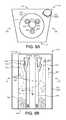
- FIG. 8Ais a schematic top view of an example canister of an evacuation station enclosing a filter and an air particle separator device.
- FIG. 8Bis a schematic side view of an example canister of an evacuation station enclosing a filter and an air particle separator device.
- FIG. 9Ais a schematic top view of an example canister of an evacuation station enclosing a two-stage air separator device.
- FIG. 9Bis a schematic side view of an example canister of an evacuation station enclosing a two-stage air separator device.
- FIG. 10Ais a schematic top view of an example canister of an evacuation station enclosing a filter bag.
- FIG. 10Bis a schematic side view of an example canister of an evacuation station enclosing a filter bag.
- FIG. 11is a schematic view of an example evacuation station.
- FIGS. 12A and 12Bare schematic views of an example flow control device for directing air flow through an air filter.
- FIG. 13is schematic view of an example controller of an evacuation station.
- FIG. 14is an example method for operating an evacuation station in first and second operation modes.
- an evacuation station 100 for evacuating debris collected by a robotic cleaner 10includes a base 120 and a canister 110 removably attached to the base 120 .
- the base 120includes a ramp 130 having a receiving surface 132 ( FIG. 3 ) for receiving and supporting a robotic cleaner 10 having a debris bin 50 .
- the ramp 130defines an evacuation intake opening 200 arranged to pneumatically interface with the debris bin 50 of the robotic cleaner 10 when robotic cleaner 10 is received on the receiving surface 132 in a docked position.
- the docked positionrefers to the receiving surface 132 in contact with and supporting wheels 22 a , of the robotic cleaner 10 .
- the ramp 130is included at an angle, ⁇ .
- the evacuation station 100may remove debris from the debris bin 50 of the robotic cleaner 10 .
- the evacuation station 100charges one or more energy storage devices (e.g., a battery 24 ) of the robotic cleaner 10 while in the docked position.
- the evacuation station 100simultaneously removes debris from the bin 50 while charging the battery 24 of the robot 10 .
- a lower portion 128 of the base 120 proximate to the ramp 130may include a profile having a radius configured to permit the robot 10 to be received and supported upon the ramp 130 .
- External surfaces of the canister 110 and the base 120may be defined by front and back walls 112 , 114 and first and second side walls 116 , 118 .
- the walls 112 , 114 , 116 , 118define a trapezoidal shaped cross section of the canister 110 and the base 120 to enable the back wall 114 of the canister 110 and the base 120 to unobtrusively abut and rest flush against a wall in the environment.
- the back wall 114may include a width (i.e., distance between the side walls 116 and 118 ) greater than a width of the front wall 112 .
- the cross section of the canister 110 and the base 120may be polygonal, rectangular, circular, elliptical or some other shape.
- the base 120 and the ramp 130 of the evacuation station 100are integral, while the canister 110 is removably attached to the base 120 (e.g., via one or more latches 124 , as shown in FIG. 4 ) to collect debris drawn from the debris bin 50 when the robot 10 is in the docked position at the evacuation station 100 .
- the one or more latches 124releasably engage with corresponding spring-loaded detents 125 ( FIG. 6 ) located on the canister 110 .
- the canister 110 and the base 120together define a height H of the evacuation station 100 .
- the canister 110includes greater than half of the defined height H. In other examples, the canister 110 includes at least two-thirds of the defined height H.
- the canister 110may attach to the base 120 when a user applies sufficient force, causing features located on the canister 110 to engage with the latches 124 disposed on the base 120 .
- a connection sensor 420( FIG. 4 ) may communicate with a controller 1300 (e.g., computing device) and sense connection of the canister 110 to the base 120 .
- the connection sensor 420includes a contact sensor (e.g., a switch or a capacitive sensor) sensing whether or not a mechanical connection exists between the one or more latches 124 and corresponding spring-loaded detents 125 located on the canister 110 .
- connection sensor 420includes an optical sensor (e.g., photointerrupter/phototransistor or infrared proximity sensor) sensing whether or not the canister 110 is connected to the base 120 .
- the canister 110may be removed or detached from the base 120 when a user pulls the canister 110 away from the base 120 releasing the latches 124 .
- the canister 110may include a handle 102 for a user to grip to transport the canister 110 .
- the canister 110detaches from the base 120 when a user pulls upward on the handle 102 .
- the canister 110includes an actuator button 102 c for releasing the latches 124 of the base 120 from the corresponding spring-loaded detents 125 located on the canister 110 when the user depresses the actuator button 102 c.
- the canister 110includes a debris ejection door button 102 a for opening a debris ejection door 662 ( FIG. 6 ) when a user presses the button 102 a to empty debris into a trash receptacle when the canister 110 is full.
- the canister 110includes a filter access door button 102 b for opening a filter access door 104 of the canister 110 when the button 102 b depresses to access a filter 650 ( FIG. 6 ) or filter bag 1050 ( FIG. 10 ) for inspection, servicing, and/or replacement.
- the buttons 102 a , 102 b , 102 cmay be located on or proximate to the handle 102 .
- the evacuation station 100may be powered by an external power source 192 via a power cord 190 .
- the external power source 192may include a wall outlet, delivering an alternating current (AC) via the power cord 190 for powering an air mover 126 ( FIG. 5 ) that causes debris to be pulled from the debris bin 50 of the robotic cleaner 10 .
- the evacuation station 100may include a DC converter 1790 ( FIG. 17 ) for powering the controller 1300 of the evacuation station 100 .
- the controller 1300receives signals and executes algorithms to determine whether or not the robotic cleaner 10 is in the docked position at the evacuation station 100 .
- the controller 1300may detect the location of the robot 10 in relation to the evacuation station 100 (via one or more sensors, such as proximity and/or contact sensors) to determine whether the robotic cleaner 10 is in the docked position.
- the controller 1300may operate the evacuation station 100 in an evacuation mode (e.g., first operation mode) to suck and collect debris from the debris bin 50 of the robotic cleaner 10 .
- an evacuation modee.g., first operation mode
- the controller 1300may operate the evacuation station 100 in an air filtration mode (e.g., second operation mode).
- an air filtration modeenvironmental air is drawn by the air mover 126 into the base 120 of the evacuation station 100 and filtered before being released to the environment.
- environmental airmay be drawn by the air mover 126 through an inlet 298 ( FIG. 5 ) of the base 120 and filtered by a particle filter 302 ( FIG. 5 ) within the base 120 and out an exhaust 300 .
- the base 120may further include a user interface 150 in communication with the controller 1300 for allowing the user to input signals for execution by the evacuation station and for displaying operation and functionality of the evacuation station 100 .
- the user interface 150may display a current capacity of the canister 110 , a remaining time for the debris bin 50 to be evacuated, a remaining time for the robot 10 to be charged, a confirmation of the robot 10 being docked, or any other pertinent parameter.
- the user interface 150 and/or controller 1300are located on the front wall 112 of the canister 110 for improved accessibility and visibility.
- FIGS. 2A and 2Billustrate an exemplary autonomous robotic cleaner 10 (also referred to as a robot) for docking with the evacuation station; however, other types of robotic cleaners are possible as well, with different components and/or different arrangements of components.
- the autonomous robotic cleaner 10includes a chassis 30 which carries an outer shell 6 .
- FIG. 2Ashows the outer shell 6 of the robot 10 connected to a front bumper 5 .
- the robot 10may move in forward and reverse drive directions; consequentially, the chassis 30 has corresponding forward and back ends 30 a , 30 b , respectively.
- the forward end 30 ais fore in the direction of primary mobility and the direction of the bumper 5 .
- the robot 10typically moves in the reverse direction primarily during escape, bounces, and obstacle avoidance.
- a collection opening 40is located toward the middle of the robot 10 and installed within the chassis 30 .
- the collection opening 40includes a first debris extractor 42 and a parallel second debris extractor 44 .
- the first debris extractor 42 and/or the parallel second debris extractor 44is/are removable.
- the collection opening 40includes a fixed first debris extractor 42 and/or a parallel second debris extractor 44 , where fixed refers to an extractor installed on and coupled to the chassis 30 , yet removable for routine maintenance.
- the debris extractors 42 and 44are composed of rubber and include flaps or vanes for collecting debris from the cleaning surface.
- the debris extractors 42 and/or 44are brushes that may be a pliable multi-vane beater or have pliable beater flaps between rows of brush bristles.
- the battery 24may be housed within the chassis 30 proximate the collection opening 40 .
- Electrical contacts 25are electrically connected to the battery 24 for providing charging current and/or voltage to the battery 24 when the robot 10 is in the docked position and is undergoing a charging event.
- the electrical contacts 25may contact associated charging contacts 252 ( FIG. 3 ) located on the ramp 130 of the evacuation station 100 .
- the forward end 30 a of the chassis 30includes a caster wheel 20 which provides additional support for the robot 10 as a third point of contact with the floor (cleaning surface) and does not hinder robot mobility.
- the removable debris bin 50is located toward the back end 30 b of the robot 10 and installed within or forms part of the outer shell 6 .
- the robot 10includes a display 8 and control panel 12 located upon the outer shell 6 .
- the display 8may display an operational mode of the robot 10 , debris capacity of the debris bin 50 , state of charge of the battery 24 , remaining life of the battery 24 , or any other parameters.
- the control panel 12may receive inputs from a user to turn on/off the robot 10 , schedule charging events for the battery 24 , select evacuation parameters for evacuating the debris bin 50 at the evacuation station 100 , or select a mode of operation for the robot 10 .
- the control panel 12may be in communication with a microprocessor 14 that executes one or more algorithms (e.g., cleaning routines) based upon the user inputs to the control panel 12 .
- the bin 50may include a bin-full detection system 250 for sensing an amount of debris present in the bin 50 .
- the bin-full detection system 250includes an emitter 252 and a detector 254 housed in the bin 50 .
- the emitter 252transmits light and the detector 254 receives reflected light.
- the bin 50includes a microprocessor 54 , which may be connected to the emitter 252 and the detector 254 , respectively, to execute an algorithm to determine whether the bin 50 is full.
- the microprocessor 54may communicate with the battery 24 and the microprocessor 14 of the robot 10 .
- the microprocessor 54may communicate with the robotic cleaner 10 from a bin serial port 56 to a robot serial port 16 .
- the robot serial port 16may be in communication with the microprocessor 14 .
- the serial ports 16 , 56may be, for example, mechanical terminals or optical devices.
- the microprocessor 54may report bin full events to the microprocessor 14 of the robotic cleaner 10 .
- the microprocessors 14 , 54may communicate with the controller 1300 to report signals when the robotic cleaner 10 has docked at the ramp 130 of the evacuation station 100 .
- the ramp 130 of the evacuation station 100may include a receiving surface 132 (having an inclination angle ⁇ with respect to the supporting ground surface) selected for facilitating access to and removal of debris residing in the debris bin 50 .
- the inclination angle ⁇may also cause debris residing in the debris bin 50 to gather at the back of the bin 50 (due to gravity) when the robot 10 is received in the docked position.
- the robot 10docks with the forward end 30 a facing the evacuation station 100 ; however other docking orientations or poses are possible as well.
- the ramp 130includes one or more charging contacts 252 disposed on the receiving surface 132 and arranged to interface with one or more corresponding electrical contacts 25 of the robotic cleaner 10 when received in the docked position.
- the controller 1300determines the robot 10 is in the docked position when the controller receives a signal indicating the charging contacts 252 are connected to the electrical contacts 25 of the robot 10 .
- the charging contacts 252may include pins, strips, plates, or other elements sufficient for conducting electrical charge.
- the charging contacts 252may guide the robotic cleaner 10 (e.g., indicate when the robotic cleaner 10 is docked).
- the ramp 130includes one or more guide alignment features 240 a - d disposed on the receiving surface 132 and arranged to orient the received robotic cleaner so that the evacuation intake opening 200 pneumatically interfaces with the debris bin 50 of the robotic cleaner 10 .
- the guide alignment features 240 a - dmay additionally be arranged to orient the received robotic cleaner so the one or more charging contacts 252 electrically connect to the electrical contacts 25 of the robotic cleaner 10 .
- the ramp 130includes wheel ramps 220 a , 220 b accepting wheels 22 a , 22 b of the robotic cleaner 10 while the robotic cleaner 10 is moving to the docked position.
- a left wheel ramp 220 aaccepts the left wheel 22 a of the robot 10 and a right wheel ramp 220 b accepts the right wheel 22 b of the robot 10 .
- Each wheel ramp 220 a , 220 bmay include an inclined surface and a pair of corresponding side walls defining a width of each wheel ramp 220 a , 220 b for retaining and aligning the wheels 22 a , 22 b of the robotic cleaner 10 upon the wheel ramps 220 a , 220 b
- the wheel ramps 220 a , 220 bmay include a width slightly greater than a width of the wheels 22 a , 22 b and may include one or more traction features for reducing slippage between the wheels 22 a , of the robotic cleaner 10 and the wheel ramps 220 a , 220 b when the robotic cleaner 10 is moving to the docked position.
- the wheel ramps 220 a , 220 bfurther function as guide alignment features for aligning the robot 10
- the one or more guide alignment featuresinclude wheel cradles 230 a , 230 b supporting the wheels 22 a , 22 b of the robotic cleaner 10 when the robotic cleaner 10 is in the docked position.
- the wheel cradles 230 a , 230 bserve to support and stabilize the wheels 22 a , 22 b when the robotic cleaner 10 is in the docked position.
- the wheel cradles 230 a , 230 binclude U-shaped depressions upon the ramp 130 having radii large enough to accept and retain the wheels 22 a , 22 b after the wheels 22 a , 22 b traverse the wheel ramps 220 a , 220 b .
- the wheel cradles 230 a , 230 bare rectangular shaped, V-shaped or other shaped depressions. Surfaces of the wheel cradles 230 a , 230 b may include a texture permitting slippage of the wheels 22 a , 22 b such that the wheels 22 a , 22 b can be rotationally aligned when at least one of the wheel cradles 230 a , 230 b accepts a corresponding wheel 22 a , 22 b .
- the cradles 230 a , 230 bmay include sensors (or features) 232 a , 232 b , respectively, indicating when the robotic cleaner 10 is in the docked position.
- the cradle sensors 232 a , 232 bmay communicate with the controller 1300 , 14 and/or 56 to determine when evacuation and/or charging events can occur.
- the cradle sensors 232 a , 232 binclude weight sensors that measure a weight of the robotic cleaner 10 when received in the docked position.
- the features 232 a , 232 bmay include biasing features that depress when the wheels 22 a , 22 b of the robot 10 are received by the cradles 230 a , 230 b , causing a signal to be transmitted to the controller 1300 , 14 and/or 54 that indicates the robot 10 is in the docked position.
- the evacuation intake opening 200is arranged to interface with the collection opening 40 of the robotic cleaner 10 .
- the evacuation intake opening 200is arranged to pneumatically interface with the debris bin 50 via the collection opening 40 so that an air flow caused by the air mover 126 draws the debris out of the debris bin 50 and through the collection and evacuation intake openings 40 , 200 , respectively, to a first conduit portion 202 a of a pneumatic debris intake conduit 202 ( FIG. 5 ) of the evacuation station 100 .
- the ramp 130also includes a seal 204 pneumatically sealing the evacuation intake opening 200 and the collection opening 40 of the robotic cleaner 10 when the robotic cleaner 10 is in the docked position.
- the drawn flow of airmay or may not cause the primary and parallel secondary debris extractors 42 , 44 , respectively, to rotate as the debris are drawn through the collection opening 40 of the robotic cleaner 10 and into the evacuation intake opening 200 of the ramp 130 .
- the base 120includes the air mover 126 having the inlet 298 and the exhaust 300 .
- the air movermoves air received from the inlet out the exhaust 300 .
- the air mover 126may include a motor and fan or impeller assembly 326 for powering the air mover 126 .
- the base 120houses a particle filter 302 pneumatically connected to the exhaust 300 of the air mover 126 .
- the particle filter 302removes small particles (e.g., between about 0.1 and about 0.5 micrometers from air received at the inlet 298 and out the exhaust 300 of the air mover 126 .
- the particle filter 302may also remove small particles (e.g., between 0.1 and about 0.5 micrometers) from environmental air received at an environmental air inlet 1230 of the air mover 126 and out the exhaust 300 of the air mover 126 .
- the particle filter 302is a high-efficiency particulate air (HEPA) filter.
- HEPAhigh-efficiency particulate air
- the particle filter 302may also be referred to as the HEPA filter and/or an air filter.
- the particle filter 302is disposable in some examples, and in other examples, the particle filter is washable to remove any small particles collected thereon.
- the base 120encloses the air mover 126 to draw a flow of air (e.g., air-debris flow 402 ) from the debris bin 50 when the robotic cleaner 10 is in the docked position and the canister 110 is attached to the base 120 .
- the first conduit portion 202 a of the pneumatic debris intake conduit 202transmits the air-debris flow 402 containing debris from the debris bin 50 to a second conduit portion 202 b of the pneumatic debris intake conduit 202 enclosed within the canister 110 .
- the second conduit portion 202 bis arranged to pneumatically interface with the first conduit portion 202 a to form the pneumatic debris intake conduit 202 when the canister 110 is attached to the base 120 .
- the pneumatic debris intake conduit 202corresponds to a single, pneumatic conduit for transporting the air-debris flow 402 that includes an air flow containing the debris drawn from the debris bin 50 of the robotic cleaner 10 through the collection and evacuation intake openings 40 , 200 , respectively.
- the canister 110includes the second conduit portion 202 b arranged to pneumatically interface with the first conduit portion 202 a to form the pneumatic debris intake conduit 202 when the canister 110 is attached to the base 120 .
- the canister 110includes an annular filter wall 650 in pneumatic communication with the second conduit portion 202 b .
- the filter wall 650may be corrugated to offer relatively greater surface area than a smooth circular wall.
- the annular filter wall 650is enclosed by a pre-filter cage 640 within the canister 110 .
- the annular filter wall 650defines an open center region 655 enclosed by an outer wall region 652 . Accordingly, the annular filter wall 650 includes an annular ring-shaped cross section.
- the annular filter wall 650corresponds to a separator that separates and/or filters debris out of the air-debris flow 402 received from the pneumatic debris intake conduit 202 .
- the air mover 126draws the air-debris flow 402 through the pneumatic debris intake conduit 202 and the annular filter wall 650 is arranged within the canister 110 to receive the air-debris flow 402 exiting the pneumatic debris intake conduit 202 at the second conduit portion 202 b .
- the annular filter wall 650collects debris from the air-debris flow 402 received from the pneumatic debris intake conduit 202 , permitting the debris-free air flow 602 to travel through the open center region 655 to the exhaust conduit 304 arranged to pneumatically connect to the inlet 298 of the air mover 126 when the canister 110 attaches to the base 120 .
- the HEPA filter 302removes any small particles (e.g., ⁇ 0.1 to ⁇ 0.5 micrometers) prior to the air exiting out to the environment at the exhaust 300 .
- a portion of the debris collected by the annular filter wall 650may be embedded upon the filter wall 650 while another portion of the debris may fall into a debris collection bin 660 within the canister 110 .
- the air-debris flow 402may be at least partially restricted from freely passing through the outer wall region 652 of the annular filter wall 650 to the open center region 655 when debris embedded upon the filter wall 650 increases. Maintenance may be performed periodically to dislodge debris from the filter wall 650 or to replace the filter wall 650 after extended use.
- the annular filter wall 650may be accessed by opening the filter access door 104 to inspect and/or replace the annular filter wall 650 as needed. For instance, the filter access door 104 may open by depressing the filter access door button 102 b located proximate the handle 102 .
- the debris collection bin 660defines a volumetric space for storing accumulated debris that falls by gravity after the annular filter wall 650 separates the debris from the air-debris flow 304 .
- the flow of aire.g., the air-debris flow 402 and/or the debris-free air flow 602
- one or more capacity sensors 170 located within the collection bin 660 or the exhaust conduit 304are utilized to detect the canister full condition, indicating that debris should be emptied from the canister 110 .
- the capacity sensors 170include light emitters/detectors arranged to detect when the debris has accumulated to a threshold level within the debris collection bin 660 indicative of the canister full condition. As the debris accumulates within the debris collection bin 660 and reaches the canister full condition, the debris at least partially blocks the air flow causing a pressure drop within the canister 110 and velocity of the flow of air to decrease.
- the capacity sensors 170include pressure sensors to monitor pressure within the canister 110 and detect the canister full condition when a threshold pressure drop occurs.
- the capacity sensors 170include velocity sensors to monitor air flow velocity within the canister 110 and detect the canister full condition when the air flow velocity falls below a threshold velocity.
- the capacity sensors 170are ultrasonic sensors whose signal changes according to the increase in density of debris within the canister so that a bin full signal only issues when the debris is compacted in the bin. This prevents light, fluffy debris stretching from top to bottom from triggering a bin full condition when much more volume is available for debris collection within the canister 110 .
- the ultrasonic capacity sensors 170are located between the vertical middle and top of the canister 110 rather than along the lower half of the canister so the signal received is not affected by debris compacting in the bottom of the canister 110 .
- the canister 110When the debris collection bin 660 is full (e.g., the canister full condition is detected), the canister 110 may be removed from the base 120 and the debris ejection door 662 may be opened to empty the debris into a trash receptacle.
- the debris ejection door 662opens when the debris ejection door button 102 a proximate the handle 102 is depressed, causing the debris ejection door 662 to swing about hinges 664 to permit the debris to empty.
- This one button press debris ejection techniqueallows a user to empty the canister 110 into a trash receptacle without having to touch the debris or any dirty surface of the canister 110 to open or close the debris ejection door 662 .
- the canister 110encloses an air particle separator device 750 (also referred to as a separator) defining at least one collision wall 756 a - h and channels arranged to direct the air-debris flow 402 received from the pneumatic debris intake conduit 202 toward the at least one collision wall 756 a - d to separate debris out of the air-debris flow 402 .
- FIG. 7illustrates an example air particle separator device 750 a including collision walls 756 a - b defining a first-stage channel 752 and collision walls 756 c - d defining a second-stage channel 754 .
- the first-stage channel 752receives the air-debris flow 402 from the second conduit portion 202 b of the pneumatic debris intake conduit 202 and directs the flow 402 by centrifugal force toward collision walls 756 a - b of the channel 752 , causing coarse debris to separate and collect within a collection bin 760 .
- the flow of air from the first-stage channel 752is received by the second-stage channel 754 .
- the second-stage channel 754directs the flow 402 upward toward collision walls 756 c - d defining the channel 754 , causing fine debris to separate and collect within the collection bin 760 .
- the air mover 126draws the debris-free air flow 602 through the exhaust conduit 304 and to the inlet 298 and out the exhaust 300 .
- small particlese.g., ⁇ 0.1 to ⁇ 0.5 micrometers
- the HEPA filter 302prior to exiting out the exhaust 300 to the environment.
- the canister 110encloses an annular filter wall 860 in pneumatic communication with an air-particle separator device 750 b for filtering and separating debris from the air-debris flow 402 received from the pneumatic debris intake conduit 202 during two stages of particle separation.
- FIG. 8Aillustrates a top view of the canister 110
- FIG. 8Billustrates a front view of the canister 110 .
- the canister 110includes a trapezoidal cross section allowing the canister 110 to rest flush against a wall in the environment to aesthetically enhance the appearance of the evacuation station 100 ; however, the canister 110 may be cylindrical with a circular cross section without limitation in other examples.
- Internal walls of the canister 110 and/or air-particle separator device 750 bmay include ribs 858 for directing air flow.
- ribsmay be disposed upon interior walls of the canister 110 in an orientation that directs debris separated by the filter 860 and/or air-particle separator device 750 b to fall away from the exhaust conduit 304 to prevent debris from being received by the inlet 298 of the air mover 126 and clogging the HEPA filter 302 .
- the air flow through the exhaust 300may be restricted if the HEPA filter 302 becomes clogged with debris.
- the filter 860may include the annular filter wall 650 defining the open center region 655 , as described above with reference to FIG. 6 .
- the air-particle separator device 750 bmay include collision walls 756 e - f defining a separator bin 852 in pneumatic communication with the open center region of the filter 860 and one or more conical separators 854 .
- the combination of the annular filter wall 860 and the air-particle separator device 750 bprovides debris to be removed from the air-debris flow 402 during two-stages of air particle separation.
- the filter 860is arranged to receive the air-debris flow 402 from the pneumatic debris intake conduit 202 .
- the filter 860separates and collects coarse debris from the received air-debris flow 402 .
- the coarse debris removed by the filter 860may accumulate within a coarse debris collection bin 862 and/or embed upon the filter 860 .
- the second stage of debris removalcommences when the air passes through the filter 860 wall and into the separator bin 852 defined by collision wall 756 e .
- the air entering the separator bin 852may be referred to as a second-stage air flow 802 .
- three conical separators 854are enclosed within the separator bin 852 ; however, the air-particle separator device 750 b may include any number of conical separators 854 .
- Each conical separator 854includes an inlet 856 for receiving the second-stage air flow 802 within the separator bin 852 .
- the conical separators 854include collision walls 756 f that angle toward each other to create a funnel (e.g., channel) that causes centrifugal force acting upon the second-stage air flow 802 to increase.
- the increasing centrifugal forcecauses the second-stage air flow 802 to spin the debris toward collision walls 756 f of the conical separators 854 , causing fine debris (e.g., dust) to separate and collect within a fine debris collection bin 864 .
- fine debrise.g., dust
- the canister 110may be removed from the base 120 and the debris ejection door 662 may be opened to empty the debris into a trash receptacle.
- a usermay open the debris ejection door 662 by depressing the debris ejection door button 102 a proximate the handle 102 , causing the debris ejection door 662 to swing about hinges 664 to permit the debris to empty from the collection bins 862 and 864 .
- This one button press debris ejection techniqueallows a user to empty the canister 110 into a trash receptacle without having to touch the debris or any dirty surface of the canister 110 to open or close the debris ejection door 662 .
- the air mover 126draws the debris-free air flow 602 from the canister 110 via the exhaust conduit 304 to the inlet 298 and out the exhaust 300 .
- small particlese.g., 0.1 to 0.5 micrometers
- within the debris-free air flow 602are removed by HEPA filter 302 prior to exiting out the exhaust 300 to the environment.
- FIGS. 9A and 9Bthe air-particle separator device 750 c is arranged in the canister 110 to receive the air-debris flow 402 from the pneumatic debris intake conduit 202 .
- FIG. 9Aillustrates a top view of the canister 110
- FIG. 9Billustrates a front view of the canister 110 .
- the canister 110includes a trapezoidal cross section allowing the canister 110 to rest flush against a wall in the environment to aesthetically enhance the appearance of the evacuation station 100 ; however, the canister 110 may include a rectangular, polygonal, circular, or other cross section without limitation in other examples. Ribs 958 may be included upon interior walls of the canister 110 and/or air-particle separator device 750 c to facilitate air flow.
- ribs 958may be disposed upon interior walls of the canister 110 and/or air-particle separator device 750 c in an orientation that directs debris separated by the air-particle separator device 750 c to fall away from the exhaust conduit 304 to prevent debris from being received by the inlet 298 of the air mover 126 and clogging the HEPA filter 302 .
- the air flow through the exhaust 300may be restricted if the HEPA filter 302 becomes clogged with debris.
- the air-particle separator device 750 cincludes one or more collision walls 756 g - h defining a first-stage separator bin 952 and one or more conical separators 954 .
- the separator bin 952includes a substantially cylindrical shape having a circular cross section. In other examples, the separator bin 952 includes a rectangular, polygonal, or other cross section.
- the first-stage separator bin 952receives the air-debris flow 402 from the pneumatic debris intake conduit 202 , wherein the separator bin 952 is arranged to channel the air-debris flow 402 toward the collision wall 756 g , causing coarse debris to separate and collect within a coarse collection bin 962 .
- the conical separators 954in pneumatic communication with the separator bin 952 , receive a second-stage air flow 902 referring to an air flow with coarse debris being removed at associated inlets 956 .
- three conical separators 954are enclosed within the first-stage separator bin 952 ; however, the air-particle separator device 750 c may include any number of conical separators 954 .
- the conical separators 954include collision walls 756 h that angle toward each other to create a funnel that causes centrifugal force acting upon the second-stage air flow 902 to increase.
- the increasing centrifugal forcedirects the second-stage air flow 902 toward the one or more collision walls 756 h , causing fine debris (e.g., dust) to separate and accumulate within a fine debris collection bin 964 .
- fine debrise.g., dust
- the canister 110may be removed from the base 120 and the debris ejection door 662 may be opened to empty the debris into a trash receptacle.
- a usermay open the debris ejection door 662 by depressing the debris ejection door button 102 a proximate the handle 102 , causing the debris ejection door 662 to swing about hinges 664 to permit the debris to empty from the collection bins 962 and 964 .
- the air mover 126draws the debris-free air flow 602 from the canister 110 via the exhaust conduit 304 to the inlet 298 and out the exhaust 300 .
- small particlese.g., 0.1 to 0.5 micrometers
- the HEPA filter 302prior to exiting out the exhaust 300 to the environment.
- the canister 110includes a filter bag 1050 arranged to receive the air-debris flow 402 from the pneumatic debris intake conduit 202 .
- the filter bag 1050corresponds to a separator that separates and filters debris out of the air-debris flow 402 received from the pneumatic debris intake conduit 202 .
- the filter bag 1050can be disposable and formed of paper or fabric that allows air to pass through but traps dirt and debris.
- FIG. 10Ashows a top view of the canister 110
- FIG. 10Bshows a side view of the canister 110 .
- the filter bag 1050while collecting debris via filtration, is porous to permit a debris-free air flow 602 to exit the filter bag 1050 via the exhaust conduit 304 . Accordingly, the debris-free air flow 602 is received by the inlet 298 of the air mover 126 and out the exhaust 300 . In some examples, small particles ( ⁇ 0.1 to ⁇ 0.5 micrometers) within the debris-free air flow 602 are removed by the HEPA filter 302 ( FIG. 5 ) disposed in the base 120 prior to exiting out the exhaust 300 ( FIG. 5 ).
- the filter bag 1050may include an inlet opening 1052 for receiving the air-debris flow 402 from the pneumatic debris intake conduit 202 exiting from the second conduit portion 202 b .
- a fitting 1054may be used to attach the inlet opening 1052 of the filter bag 1050 to an outlet of the second conduit portion 202 b of the pneumatic air-debris intake conduit 202 .
- the fitting 1054includes features that poka-yoke mating the filter bag 1050 so that the bag only mates to the fitting 1054 in a proper orientation for use and expansion within the canister 110 .
- the filter bag 1050includes a matching interface with features accommodating those on the fitting 1054 .
- the filter bag 1050is disposable, requiring replacement when the filter bag 1050 becomes full. In other examples, the filter bag 1050 may be removed from the canister 110 and collected debris may be emptied from the filter bag 1050 .
- the filter bag 1050may be accessed for inspection, maintenance and/or replacement by opening the filter access door 104 .
- the filter access door 104swings about hinges 1004 .
- the filter access door 104is opened by depressing the filter access door button 102 b located proximate the handle 102 .
- the filter bag 1050may provide varying degrees of filtration (e.g., ⁇ 0.1 microns to ⁇ 1 microns).
- the filter bag 1050includes HEPA filtration in addition to, or instead of, the HEPA filter 302 located proximate the exhaust 300 within the base 120 of the evacuation station 100 .
- the canister 110includes a filter bag detection device 1070 configured to detect whether or not the filter bag 1050 is present.
- the filter bag detection device 1070may include light emitters and detectors configured to detect the presence of the filter bag 1050 .
- the filter bag detection device 1070may relay signals to the controller 1300 .
- the filter detection device 1070detects the filter bag 1050 is not within the canister 110 , the filter detection device 1070 prevents the filter access door 104 from closing.
- the controller 1300may activate mechanical features or latches proximate the canister 110 and/or filter access door 104 to prevent the filter access door 104 from closing.
- the filter bag detection device 1070is mechanical and movable between a first position for preventing the filter access door 104 from closing and a second position for allowing the filter access door 104 to close.
- a fitting 1054swings or moves upward when the filter bag 1050 is removed and prevents the filter door 104 from closing. The fitting 1054 is depressed upon insertion of the filter bag 1050 allowing the filter door 104 to close.
- detecting when the filter bag 1050 is not present in the canister 110prevents the evacuation station 100 from operating in the evacuation mode, even if the robotic cleaner 10 is received at the ramp 130 in the docked position.
- the evacuation station 100were to operate in the evacuation mode when the filter bag 1050 is not present, debris contained in the air-debris flow 402 may become dislodged within the canister 110 , exhaust conduit 304 , and/or air mover 126 , restricting the flow of air to the exhaust 300 as well as causing damage to the motor and fan or impeller assembly 326 ( FIG. 5 ).
- the canister 110includes a trapezoidal cross section allowing the canister 110 to rest flush against a wall in the environment to aesthetically enhance the appearance of the evacuation station 100 .
- the canister 110may however, include a rectangular, polygonal, circular, or other cross section without limitation in other examples.
- the filter bag 1050expands as the collected debris accumulates therein. Expansion of the filter bag 1050 into contact with interior walls 1010 of the canister 110 may result in debris only accumulating at a bottom portion of the filter bag 1050 , thereby chocking the air flow through the filter bag 1050 .
- the filter bag 1050 and/or interior walls 1010 of the canister 110include protrusions 1080 , such as ribs, edges or ridges, disposed upon and extending away from the exterior surface of the filter bag 1050 and/or extending into the canister 110 from the interior walls 1010 .
- protrusions 1080such as ribs, edges or ridges
- the protrusions 1080 on the bag 1050abut against the interior walls 1010 of the canister 110 to prevent the filter bag 1050 from fully expanding into the interior walls 1010 .
- the protrusions 1080restrict the bag 1050 from fully expanding into flush contact with the interior walls 1010 .
- the protrusions 1080ensure that an air gap is maintained between the filter bag 1050 and the interior walls 1010 , such that the filter bag 1050 cannot fully expand into contact the interior walls 1010 .
- the protrusions 1080are elongated ribs uniformly spaced in parallel around the exterior surface of the filter bag 1050 and/or the surface of the interior walls 1010 . The spacing between adjacent protrusions 1080 is small enough to prevent the filter bag 1050 from bowing out and into contact with the interior walls.
- the canister 110is cylindrical and the protrusions 1080 are elongated ribs that run vertically down the length of the canister 110 and around the entire circumference of the canister 110 such that airflow continues to be uniform through the entire surface of the unfilled portion of bag even as debris compacts in the bottom of the bag.
- FIG. 11shows a schematic view of an example evacuation station 100 including an air particle separator device 750 and an air filtration device 1150 .
- the evacuation station 100includes a base 120 , a collection bin 1120 and a ramp 130 for docking with the autonomic robotic cleaner 10 .
- the example robotic cleaner 10 docking with the ramp 130is described above with reference to FIGS. 1-5 ; however, other types of robots 10 are possible as well.
- the base 120houses a first air mover 126 a (e.g. a motor driven vacuum impeller) and the air particle separator device 750 .
- the first air mover 126 adraws an air-debris flow 402 through a pneumatic debris intake conduit 202 to pull debris from within the debris bin 50 of the robotic 10 .
- the pneumatic debris intake conduit 202provides the air-debris flow 402 from the debris bin 50 to a single stage particle separator 1152 of the air particle separator device 750 .
- the centrifugal force created by the geometry of the single stage particle separator 1152causes the air-debris flow 402 to direct toward one or more collision walls 756 of the separator 1152 , causing particles to fall from the drawn air 402 and collect in the collection bin 1120 disposed beneath the single stage particle separator 1152 .
- a filter 1154may be disposed above the single stage particle separator 1152 to prevent debris from being drawn up and through the first air mover 126 a and damaging the first air mover 126 a.
- a second air mover 126 b of the air filtration device 1150provides suction and draws the debris-free air flow 602 from the air mover 126 a through and into the air filtration device 1150 .
- the second air mover 126 b of the air filtration device 1150includes a fan/fin/impeller that spins.
- a particle filter 302may remove small particles (e.g., ⁇ 0.1 to ⁇ 0.5 microns) from the debris-free air flow 602 .
- the particle filter 302is a HEPA filter 302 as described above with reference to FIGS. 4 and 5 . Upon passing through the air particle filter 302 , the debris-free air flow 602 may exhaust into the environment external to the evacuation station 100 .
- the air filtration device 1150may further operate as an air filter for filtering environmental air external to the evacuation station 100 .
- the second air mover 126 bmay draw the environmental air 1102 to pass through the HEPA filter 302 .
- the air filtration device 1150filters the environmental air via the HEPA filter 302 when the robot 10 is not received in the docked position, and/or the debris bin 50 of the robot 10 is not being evacuated.
- the air filtration device 1150simultaneously draws environmental air 1102 and debris-free flow 602 exiting the air particle separator device 750 through the HEPA filter 302 .
- the collection bin 1120is removably attached to the base 120 .
- the collection bin 1120includes a handle 1122 for carrying the collection bin 1120 when removed from the base 120 .
- the collection bin 1120may be detached from the base 120 when the handle 1122 is pulled by the user.
- the usermay transport the collection bin 1120 via the handle 1122 to empty the collected debris when the collection bin 1120 is full.
- the collection bin 1120may include a button-press actuated debris ejection door, similar to the debris ejection door 662 described above with reference to FIG. 6 . This one button press debris ejection technique allows a user to empty the collection bin 1120 into a trash receptacle without having to touch the debris or any dirty surface of the collection bin 1120 to open or close the debris ejection door 662 .
- an example evacuation station 100includes a flow control device 1250 in communication with a controller 1300 that selectively actuates the flow control device 1250 between a first position ( FIG. 12A ) when the evacuation station 100 operates in an evacuation mode and a second position ( FIG. 12B ) when the evacuation station 100 operates in an air filtration mode.
- the flow control device 1250is a flow control valve spring biased toward the first position or the second position. The flow control device 1250 may be actuated between the first and second positions to selectively block one air flow passage or another.
- the evacuation station 100may operate in the evacuation mode to evacuate debris from the debris bin 50 of the robotic cleaner 10 .
- the controller 1300activates an air mover 126 (motor and impeller) and actuates the flow control device 1250 to the first position, pneumatically connecting the pneumatic debris intake conduit 202 to the inlet 298 of the air mover 126 .
- An air-debris flow 402may be drawn by the air mover 126 through the pneumatic debris intake conduit 202 .
- the canister 110may enclose a filter 1260 in pneumatic communication with the pneumatic debris intake conduit 202 for filtering/separating debris out of the air-debris flow 402 . Additionally or alternatively, the canister 110 may enclose an air particle separator device 750 for separating the debris out of the air-debris flow 402 , as discussed in the examples above.
- a debris collection bin 660may store accumulated debris that fall by gravity after being separated from the air-debris flow 304 by the filter 1260 .
- the flow control device 1250 in the first positionpneumatically connects the exhaust conduit 304 to the inlet of 298 of the air mover 126 .
- a debris-free air flow 602may travel through the exhaust conduit 304 and into the air mover 126 and out the exhaust 300 when the flow control device 1250 is in the first position associated with the evacuation mode.
- the flow control device 1250while in the first position, also blocks environmental air 1202 ( FIG. 12B ) from being drawn by the air mover 126 through an environmental air inlet 1230 of the air mover 126 and out the exhaust 300 .
- the evacuation station 100may operate in the air filtration mode.
- the controller 1300activates the air mover 126 and actuates the flow control device 1250 to the second position, pneumatically connecting the environmental air inlet 1230 to the exhaust 300 of the air mover 126 while pneumatically disconnecting the inlet 298 of the air mover 126 from the exhaust conduit 304 .
- the air mover 126may draw the environmental air 1202 via the environmental air inlet 1230 to pass through an air particle filter 302 such as a HEPA filter described above.
- the environmental air 1202may travel out the exhaust 300 and back into the environment. Since the flow control device 1250 in the second position pneumatically disconnects the inlet 298 from the exhaust conduit 304 , no air flow is drawn by the air mover 126 through the pneumatic debris intake conduit 202 or the exhaust conduit 304 .
- the air particle filter 302e.g., HEPA filter
- air flow generated within the debris bin 50 of the robot 10 during the evacuation modeallows debris in the bin 50 to be sucked out and transported to the evacuation station 100 .
- the air flow within the debris bin 50must be sufficient to permit the debris to be removed while avoiding damage to the bin 50 and a robot motor (not shown) housed within the bin 50 .
- the robot motormay generate an air flow to draw debris from the collection opening 40 into the bin 50 to collect the debris within the bin 50 , while permitting the air flow to exit the bin 50 through an exhaust vent (not shown) proximate the robot motor.
- the evacuation stationcan be used, for example, with a bin such as that disclosed in U.S. patent application Ser. No. 14/566,243, filed Dec. 10, 2014 and entitled, “DEBRIS EVACUATION FOR CLEANING ROBOTS”, which is hereby incorporated by reference in its entirety.
- FIG. 13shows an example controller 1300 enclosed within the evacuation station 100 .
- the external power supply 192e.g., wall outlet
- the DC converter 1390may convert AC current from the power supply 192 into DC current for powering the controller 1300 .
- the controller 1300includes a motor module 1702 in communication with the air mover 126 using AC current from the external power supply 192 .
- the motor module 1302may further monitor operational parameters of the air mover 126 such as, but not limited to, rotational speed, output power, and electrical current.
- the motor module 1302may activate the air mover 126 .
- the motor module 1302actuates the flow control valve 1250 between the first and second positions.
- the controller 1300includes a canister module 1304 receiving a signal indicating a canister full condition when the canister 110 has reached its capacity for collecting debris.
- the canister module 1304may receive signals from the one or more capacity sensors 170 located within the canister (e.g., collection chambers or exhaust conduit 304 ) and determine when the canister full condition is received.
- an interface module 1306communicates the canister full condition to the user interface 150 by displaying a message indicating the canister full condition.
- the canister module 1304may receive a signal from the connection sensor 420 indicating if the canister 110 is attached to the base 120 or if the canister 110 is removed from the base 120 .
- a charging module 1308receives an indication of electrical connection between the one or more charging contacts 252 and the one or more a corresponding electrical contacts 25 .
- the indication of electrical connectionmay indicate the robotic cleaner 10 is received in the docked position.
- the controller 1300may execute the first operation mode (e.g., evacuation mode) when the electrical connection indication is received at the charging module 1308 .
- the charging module 1308receives an indication of electrical disconnection between the one or more charging contacts 252 and the one or more a corresponding electrical contacts 25 .
- the indication of electrical disconnectionmay indicate the robotic cleaner 10 is not received in the docked position.
- the controller 1300may execute the second operation mode (e.g., air filtration mode) when the electrical disconnection indication is received at the charging module 1308 .
- the controller 1300may detect when the charging contacts 252 located upon the ramp 130 are in contact with the electrical contacts 25 of the robotic cleaner 10 .
- the charging module 1308may determine the robotic cleaner 10 has docked with the evacuation station 100 when the electrical contacts 25 are in contact with the charging contacts 252 .
- the charging module 1308may communicate the docking determination to the motor module 1302 so that the air mover 126 may be powered to commence evacuating the debris bin 50 of the robotic cleaner 10 .
- the charging module 1308may further monitor the charge of the battery 24 of the robotic cleaner 10 based on signals communicated between the charging and electrical contacts 25 , 252 , respectively. When the battery 24 needs charging, the charging module 1308 may provide a charging current for powering the battery.
- the charging module 1308may block the supply of charging through the electrical contacts 25 of the battery 24 .
- the charging module 1308provides a state of charge or estimated charge time for the battery 24 to the interface module 1306 for display upon the user interface 150 .
- the controller 1300includes a guiding module 1310 that receives signals from the guiding device 122 (emitter 122 a and/or detector 122 b ) located on the base 120 . Based upon the signals received from the guiding device 122 , the guiding module may determine when the robot 10 is received in the docked position, determine a location of the robot 10 , and/or assist in guiding the robot 10 to toward the docked position.
- the guiding module 1310may additionally or alternatively receive signals from sensors 232 a , 232 b (e.g., weight sensors) for detecting when the robot 10 is in the docked position.
- the guiding module 1310may communicate to the motor module 1302 when the robot 10 is received in the docked position so that the air mover 126 can activated for drawing out debris from the debris bin 50 of the robot.
- a bin module 1312 of the controller 1300may indicate a capacity of the debris bin 50 of the robotic cleaner 10 .
- the bin module 1312may receive signals from the microprocessor 14 and/or 54 of the robot 10 and the capacity sensor 170 that indicate the capacity of the bin 50 , e.g., the bin full condition.
- the robot 10may dock when the battery 24 is in need of charging but the bin 50 is not full of debris.
- the bin module 1312may communicate to the motor module 1302 that evacuation is no longer needed.
- the bin module 1312may receive a signal indicating that the bin 50 no longer requires evacuation and the motor module 1302 may be notified to deactivate the air mover 126 .
- the bin module 1312may receive a collection bin identification signal from the microprocessor 14 and/or 54 of the robot 10 that indicates a model type of the debris bin 50 used by the robotic cleaner 10 .
- the interface module 1306receives operational commands input by a user to the user interface 150 , e.g., an evacuation schedule and/or charging schedule for evacuating and/or charging the robot 10 . For instance, it may be desirable to charge and/or evacuate the robot 10 at specific times even though the bin 50 is not full and/or the battery 24 is not entirely depleted.
- the interface module 1306may notify the guiding module 1310 to transmit honing signals through the guiding device 122 to call the robot 10 to dock during the time of a set charging and/or evacuation event specified by the user.
- FIG. 14provides an example arrangement of operations for a method 1400 , executable by the controller 1300 of FIG. 13 , for operating the evacuation station 100 between an evacuation mode (e.g., a first operation mode) and an air filtration mode (e.g., a second operation mode).
- the flowchartstarts at operation 1402 where the controller 1300 receives a first indication of whether the robotic cleaner 10 is received on the receiving surface 132 in the docked position, and at operation 1404 , receives a second indication of whether the canister 110 is connected to the base 120 .
- the controller 1300may receive the first and second indications of operations 1802 , 1804 , respectively, in any order or in parallel.
- the first indicationincludes the controller 1300 receiving an electrical signal from the one or more charging contacts 252 disposed on the receiving surface 132 that interface with electrical contacts 25 when the robotic cleaner 10 is in the docked position.
- the second indicationincludes the controller 1300 receiving a signal from the connection sensor 420 sensing connection of the canister 110 to the base 120 .
- the controller 1300executes the evacuation mode (first operation mode) at operation 1408 by actuating the flow control device 1250 to move to the first position ( FIG. 12A ) that pneumatically connects the evacuation intake opening 200 to the canister 110 and activates the air mover 126 to draw air into the evacuation intake opening 200 to draw debris from the debris bin 50 of the docked robotic cleaner 10 into the canister 110 .
- the controller 1300executes the air filtration mode (second operation mode) by actuating the flow control valve 1250 to move to the second position ( FIG. 12B ) that pneumatically connects the environmental air inlet 1230 ( FIGS. 12A and 12B ) to the exhaust 300 of the air mover 126 while pneumatically disconnecting the inlet 298 of the air mover 126 from the exhaust conduit 304 .
- the air filtration modesecond operation mode
- the air mover 126may draw environmental air 1202 through the environmental air inlet 1230 and the particle filter 302 and out the exhaust 300 .
- operation 1408additionally detects whether or not the evacuation mode is executing or has recently stopped executing.
- the controller 1300executes the air filtration mode even though the canister 110 is attached to the base 120 and the robotic cleaner 10 is received in the docked position.
Landscapes
- Engineering & Computer Science (AREA)
- Mechanical Engineering (AREA)
- Robotics (AREA)
- Electric Vacuum Cleaner (AREA)
- Electric Suction Cleaners (AREA)
- Filters For Electric Vacuum Cleaners (AREA)
Abstract
Description
Claims (23)
Priority Applications (4)
| Application Number | Priority Date | Filing Date | Title |
|---|---|---|---|
| US15/901,952US10463215B2 (en) | 2014-12-24 | 2018-02-22 | Evacuation station |
| US16/592,403US10595692B2 (en) | 2014-12-24 | 2019-10-03 | Evacuation station |
| US16/827,389US11969139B2 (en) | 2014-12-24 | 2020-03-23 | Evacuation station |
| US18/649,714US20240407615A1 (en) | 2014-12-24 | 2024-04-29 | Evacuation Station |
Applications Claiming Priority (3)
| Application Number | Priority Date | Filing Date | Title |
|---|---|---|---|
| US201462096771P | 2014-12-24 | 2014-12-24 | |
| US14/944,788US9931007B2 (en) | 2014-12-24 | 2015-11-18 | Evacuation station |
| US15/901,952US10463215B2 (en) | 2014-12-24 | 2018-02-22 | Evacuation station |
Related Parent Applications (1)
| Application Number | Title | Priority Date | Filing Date |
|---|---|---|---|
| US14/944,788ContinuationUS9931007B2 (en) | 2014-12-24 | 2015-11-18 | Evacuation station |
Related Child Applications (1)
| Application Number | Title | Priority Date | Filing Date |
|---|---|---|---|
| US16/592,403ContinuationUS10595692B2 (en) | 2014-12-24 | 2019-10-03 | Evacuation station |
Publications (2)
| Publication Number | Publication Date |
|---|---|
| US20180177369A1 US20180177369A1 (en) | 2018-06-28 |
| US10463215B2true US10463215B2 (en) | 2019-11-05 |
Family
ID=56151315
Family Applications (5)
| Application Number | Title | Priority Date | Filing Date |
|---|---|---|---|
| US14/944,788Active2036-08-02US9931007B2 (en) | 2014-12-24 | 2015-11-18 | Evacuation station |
| US15/901,952ActiveUS10463215B2 (en) | 2014-12-24 | 2018-02-22 | Evacuation station |
| US16/592,403ActiveUS10595692B2 (en) | 2014-12-24 | 2019-10-03 | Evacuation station |
| US16/827,389Active2036-06-12US11969139B2 (en) | 2014-12-24 | 2020-03-23 | Evacuation station |
| US18/649,714PendingUS20240407615A1 (en) | 2014-12-24 | 2024-04-29 | Evacuation Station |
Family Applications Before (1)
| Application Number | Title | Priority Date | Filing Date |
|---|---|---|---|
| US14/944,788Active2036-08-02US9931007B2 (en) | 2014-12-24 | 2015-11-18 | Evacuation station |
Family Applications After (3)
| Application Number | Title | Priority Date | Filing Date |
|---|---|---|---|
| US16/592,403ActiveUS10595692B2 (en) | 2014-12-24 | 2019-10-03 | Evacuation station |
| US16/827,389Active2036-06-12US11969139B2 (en) | 2014-12-24 | 2020-03-23 | Evacuation station |
| US18/649,714PendingUS20240407615A1 (en) | 2014-12-24 | 2024-04-29 | Evacuation Station |
Country Status (8)
| Country | Link |
|---|---|
| US (5) | US9931007B2 (en) |
| EP (2) | EP3236827B1 (en) |
| JP (3) | JP7098113B2 (en) |
| CN (3) | CN107405031B (en) |
| AU (2) | AU2015370307B2 (en) |
| CA (1) | CA2972252C (en) |
| ES (1) | ES2829919T3 (en) |
| WO (1) | WO2016105702A1 (en) |
Cited By (18)
| Publication number | Priority date | Publication date | Assignee | Title |
|---|---|---|---|---|
| USD895915S1 (en)* | 2017-09-07 | 2020-09-08 | Sharkninja Operating Llc | Side brush for robotic vacuum cleaner |
| USD903961S1 (en)* | 2020-03-10 | 2020-12-01 | Shenzhen Modern Business Trading Co., Ltd. | Robotic vacuum cleaner |
| USD906608S1 (en)* | 2020-03-25 | 2020-12-29 | Shenzhen WoMei Tech Co., Ltd. | Robotic vacuum cleaner |
| USD906236S1 (en)* | 2018-08-03 | 2020-12-29 | Techtronic Cordless Gp | Docking station for mowers |
| US11134818B2 (en) | 2018-12-14 | 2021-10-05 | Samsung Electronics Co., Ltd. | Cleaning apparatus having vacuum cleaner and docking station |
| US11234572B2 (en)* | 2018-05-01 | 2022-02-01 | Sharkninja Operating Llc | Docking station for robotic cleaner |
| WO2022131710A1 (en) | 2020-12-16 | 2022-06-23 | 엘지전자 주식회사 | Cleaner system |
| US11375866B2 (en)* | 2018-08-30 | 2022-07-05 | Irobot Corporation | Control of evacuation stations |
| US11452418B2 (en) | 2019-08-05 | 2022-09-27 | Samsung Electronics Co., Ltd. | Station of robot cleaner |
| USD965517S1 (en)* | 2020-10-19 | 2022-10-04 | Amazon Technologies, Inc. | Docking station |
| US20230055824A1 (en)* | 2020-06-25 | 2023-02-23 | Samsung Electronics Co., Ltd. | Docking station, mobile robot, and mobile robot management system for controlling docking station and mobile robot |
| USD981061S1 (en)* | 2021-04-12 | 2023-03-14 | Zhichang Technology (Suzhou) Co., Ltd. | Cleaning robot workstation |
| DE112022000449T5 (en) | 2021-02-22 | 2023-10-05 | Lg Electronics Inc. | Cleaning station |
| US11969139B2 (en) | 2014-12-24 | 2024-04-30 | Irobot Corporation | Evacuation station |
| US12296694B2 (en) | 2021-03-10 | 2025-05-13 | Techtronic Cordless Gp | Lawnmowers |
| US12369509B2 (en) | 2022-07-19 | 2025-07-29 | Techtronic Cordless Gp | Display for controlling robotic tool |
| US12425197B2 (en) | 2022-07-29 | 2025-09-23 | Techtronic Cordless Gp | Generation of a cryptography key for a robotic garden tool |
| US12443180B2 (en) | 2022-11-09 | 2025-10-14 | Techtronic Cordless Gp | Robotic lawn mowers |
Families Citing this family (176)
| Publication number | Priority date | Publication date | Assignee | Title |
|---|---|---|---|---|
| USD784640S1 (en)* | 2015-02-12 | 2017-04-18 | Irobot Corporation | Robot |
| USD790141S1 (en)* | 2015-02-12 | 2017-06-20 | Irobot Corporation | Robot |
| USD796757S1 (en)* | 2015-02-12 | 2017-09-05 | Irobot Corporation | Robot |
| USD771333S1 (en)* | 2015-02-12 | 2016-11-08 | Irobot Corporation | Cleaning robot |
| USD781512S1 (en)* | 2015-02-12 | 2017-03-14 | Irobot Corporation | Robot |
| USD771332S1 (en)* | 2015-02-12 | 2016-11-08 | Irobot Corporation | Cleaning robot |
| US9462920B1 (en) | 2015-06-25 | 2016-10-11 | Irobot Corporation | Evacuation station |
| US11163311B2 (en) | 2015-12-24 | 2021-11-02 | Partnering 3.0 | Robotic equipment including a mobile robot, method for recharging a battery of such mobile robot, and mobile robot docking station |
| FR3046245B1 (en)* | 2015-12-24 | 2018-02-16 | Partnering 3.0 | AIR QUALITY MONITORING SYSTEM AND RECEPTION STATION FOR MOBILE ROBOT EQUIPPED WITH AIR QUALITY SENSORS |
| JP6660738B2 (en)* | 2016-01-12 | 2020-03-11 | 東芝ライフスタイル株式会社 | Electric cleaning equipment |
| DE102016114338A1 (en)* | 2016-08-03 | 2018-02-08 | Miele & Cie. Kg | Charger for a household appliance and method for charging a household appliance |
| US10456002B2 (en) | 2016-12-22 | 2019-10-29 | Irobot Corporation | Cleaning bin for cleaning robot |
| US11794141B2 (en)* | 2021-01-25 | 2023-10-24 | Omachron Intellectual Property Inc. | Multiuse home station |
| US11305663B2 (en)* | 2017-03-27 | 2022-04-19 | General Electric Company | Energy efficient hands-free electric vehicle charger for autonomous vehicles in uncontrolled environments |
| US20180344116A1 (en)* | 2017-06-02 | 2018-12-06 | Irobot Corporation | Scheduling and control system for autonomous robots |
| USD835869S1 (en)* | 2017-06-14 | 2018-12-11 | Guangdong Bona Robot Co., Ltd | Cleaning robot |
| US10941555B2 (en) | 2017-06-16 | 2021-03-09 | Altan Robotech Inc. | Robotic cleaning apparatus and related methods |
| US10941553B2 (en) | 2017-06-16 | 2021-03-09 | Altan Robotech Inc. | Robotic cleaning apparatus and related methods |
| USD843671S1 (en)* | 2017-07-25 | 2019-03-19 | Sharkninja Operating Llc | Robotic vacuum cleaner |
| USD838069S1 (en) | 2017-08-17 | 2019-01-08 | Altan Robotech Inc. | Cleaning robot |
| USD840617S1 (en)* | 2017-08-31 | 2019-02-12 | Beijing Xiaomi Mobile Software Co., Ltd. | Robotic vacuum |
| US10383499B2 (en)* | 2017-08-31 | 2019-08-20 | Irobot Corporation | Wet robot docking station |
| USD877432S1 (en) | 2017-09-07 | 2020-03-03 | Sharkninja Operating Llc | Bumper for robotic vacuum cleaner |
| USD867987S1 (en)* | 2017-09-15 | 2019-11-26 | Beijing Rockrobo Technology Co., Ltd. | Base station |
| US11980334B2 (en) | 2017-09-15 | 2024-05-14 | Omachron Intellectual Property Inc. | Surface cleaning apparatus |
| CN107608360B (en)* | 2017-10-26 | 2024-09-06 | 深圳银星智能集团股份有限公司 | Mobile robot |
| CN107669216A (en)* | 2017-11-24 | 2018-02-09 | 珠海市微半导体有限公司 | Intelligent cleaning system and intelligent cleaning method |
| DE102018204172A1 (en)* | 2017-12-27 | 2019-06-27 | Robert Bosch Gmbh | Battery-suction device |
| US10737395B2 (en)* | 2017-12-29 | 2020-08-11 | Irobot Corporation | Mobile robot docking systems and methods |
| US10967749B2 (en)* | 2017-12-29 | 2021-04-06 | Irobot Corporation | Electrostatic discharge systems for autonomous mobile robots |
| DE102018100371A1 (en)* | 2018-01-09 | 2019-07-11 | Vorwerk & Co. Interholding Gmbh | Vacuum cleaning device with a filter bag and filter bag for a vacuum cleaning device |
| US11144066B1 (en)* | 2018-01-31 | 2021-10-12 | AI Incorporated | Autonomous refuse bag replacement system |
| USD890231S1 (en) | 2018-05-04 | 2020-07-14 | Irobot Corporation | Debris container |
| USD924522S1 (en) | 2018-05-04 | 2021-07-06 | Irobot Corporation | Evacuation station |
| USD908993S1 (en) | 2018-05-04 | 2021-01-26 | Irobot Corporation | Evacuation station |
| USD893561S1 (en) | 2018-05-04 | 2020-08-18 | Irobot Corporation | Debris container |
| USD930053S1 (en) | 2018-05-04 | 2021-09-07 | Irobot Corporation | Debris container |
| USD908992S1 (en) | 2018-05-04 | 2021-01-26 | Irobot Corporation | Evacuation station |
| US10842334B2 (en)* | 2018-05-04 | 2020-11-24 | Irobot Corporation | Filtering devices for evacuation stations |
| USD893562S1 (en) | 2018-05-04 | 2020-08-18 | Irobot Corporation | Debris container |
| KR102071959B1 (en)* | 2018-05-16 | 2020-04-01 | 엘지전자 주식회사 | A Recharger Deck for a Robot Vacuum Cleaner |
| GB2574198B (en)* | 2018-05-25 | 2020-11-04 | Sony Interactive Entertainment Inc | Apparatus, system and method of wireless robot charging |
| MY206343A (en)* | 2018-06-22 | 2024-12-12 | Bissell Inc | Surface cleaning apparatus and tray |
| TWI668591B (en)* | 2018-06-28 | 2019-08-11 | 廣達電腦股份有限公司 | Robotic system |
| CN115089055B (en)* | 2018-07-20 | 2024-02-13 | 尚科宁家运营有限公司 | Docking station and cleaning system for robotic cleaner |
| US11039725B2 (en) | 2018-09-05 | 2021-06-22 | Irobot Corporation | Interface for robot cleaner evacuation |
| CA3116593A1 (en)* | 2018-10-22 | 2020-04-30 | Omachron Intellectual Property Inc. | Air treatment apparatus |
| US11609573B2 (en)* | 2018-10-30 | 2023-03-21 | Florida Power & Light Company | Method for the automated docking of robotic platforms |
| CN109480713B (en)* | 2018-12-20 | 2023-09-19 | 北京享捷科技有限公司 | Dust collection device and dust collection method for sweeping robot |
| CN109480714B (en) | 2018-12-25 | 2023-10-03 | 北京享捷科技有限公司 | Dust collection and charging device and dust collection and charging method for sweeping robot |
| CN109662657A (en)* | 2019-01-07 | 2019-04-23 | 云鲸智能科技(东莞)有限公司 | Base station and docking method |
| USD948143S1 (en) | 2019-02-19 | 2022-04-05 | Sharkninja Operating Llc | Robotic vacuum cleaner |
| UA41384S (en)* | 2019-03-18 | 2020-04-27 | Бейцзін Сяомі Мо | CHARGER FOR CLEANING DEVICE |
| CN111743459B (en)* | 2019-03-29 | 2024-07-16 | 北京石头世纪科技股份有限公司 | Intelligent cleaning system, autonomous robot and base station |
| USD906607S1 (en)* | 2019-04-18 | 2020-12-29 | Zhuhai Kaihao Electronics Co., Ltd. | Robotic vacuum cleaner |
| CN110027827B (en)* | 2019-04-30 | 2024-07-26 | 深圳银星智能集团股份有限公司 | Treatment station and cleaning system |
| CN110051283B (en)* | 2019-05-17 | 2023-06-09 | 珠海市一微机器人技术有限公司 | Intelligent garbage collection robot facing sweeping robot |
| CN112043204B (en)* | 2019-06-05 | 2021-11-26 | 美智纵横科技有限责任公司 | Air treatment component and cleaning equipment with same |
| USD939436S1 (en) | 2019-06-14 | 2021-12-28 | Sharkninja Operating Llc | Auto-emptying docking station |
| USD947473S1 (en) | 2019-06-14 | 2022-03-29 | Sharkninja Operating Llc | Robot vacuum |
| DE102019004417A1 (en)* | 2019-06-25 | 2020-12-31 | Vorwerk & Co. Interholding Gmbh | Method, base station and cleaning system for vacuuming a cleaning device |
| ES2953125T3 (en)* | 2019-07-11 | 2023-11-08 | Vorwerk Co Interholding | Base station for connecting a cleaning device and procedure for operating a cleaning system |
| USD951859S1 (en)* | 2019-08-15 | 2022-05-17 | Beijing Xiaomi Mobile Software Co., Ltd. | Charging base for robot vacuum cleaner |
| CN110623605B (en)* | 2019-08-21 | 2021-11-30 | 深圳市无限动力发展有限公司 | Workstation and cleaning system |
| CN110466918B (en)* | 2019-08-21 | 2022-08-05 | 深圳市无限动力发展有限公司 | Garbage recycling station and cleaning system |
| KR102208334B1 (en)* | 2019-09-05 | 2021-01-28 | 삼성전자주식회사 | Cleaning device having vacuum cleaner and docking station and control method thereof |
| CN110601291A (en)* | 2019-09-17 | 2019-12-20 | 南通明诺电动科技股份有限公司 | Electronic quick-witted charging base of sweeping floor of magnetism formula intelligence |
| KR102774726B1 (en) | 2019-09-25 | 2025-03-04 | 삼성전자주식회사 | Robot cleaner and control method thereof |
| KR20210045784A (en)* | 2019-10-17 | 2021-04-27 | 엘지전자 주식회사 | Cleaner System |
| CN110840334B (en)* | 2019-11-05 | 2021-05-28 | 深圳市银星智能科技股份有限公司 | Machine cleaning system and maintenance method thereof |
| CN110859550A (en)* | 2019-11-07 | 2020-03-06 | 珠海格力电器股份有限公司 | Dust collection method, device, dust collection system and readable storage medium |
| CN110811437A (en)* | 2019-11-07 | 2020-02-21 | 珠海格力电器股份有限公司 | Dust collection method, dust collection device, cleaning system and readable storage medium |
| DE102019131582A1 (en)* | 2019-11-22 | 2021-05-27 | Vorwerk & Co. Interholding Gmbh | Vacuum cleaning device, system with a vacuum cleaning device and a base station and method for operating such a system |
| DE102019131662A1 (en)* | 2019-11-22 | 2021-05-27 | Vorwerk & Co. Interholding Gmbh | Base station for a soil cultivation device, drive wheel for a soil cultivation device and a system comprising a base station and a soil cultivation device |
| CN110974090B (en)* | 2019-12-24 | 2021-11-16 | 深圳市银星智能科技股份有限公司 | Emptying station and cleaning robot system with same |
| CN113017486B (en)* | 2019-12-25 | 2024-08-30 | 美智纵横科技有限责任公司 | Dust collecting station and cleaning system |
| CN111035326A (en)* | 2019-12-28 | 2020-04-21 | 尚科宁家(中国)科技有限公司 | Robot evacuation station and robot system of sweeping floor sweep |
| CN113040650A (en)* | 2019-12-28 | 2021-06-29 | 尚科宁家(中国)科技有限公司 | Dust collecting station for sweeping robot |
| CN111110123A (en)* | 2019-12-28 | 2020-05-08 | 尚科宁家(中国)科技有限公司 | Emptying station for sweeping robot |
| CN113040649B (en)* | 2019-12-28 | 2022-12-06 | 尚科宁家(中国)科技有限公司 | Dust collecting station for sweeping robot |
| KR20210086457A (en)* | 2019-12-30 | 2021-07-08 | 엘지전자 주식회사 | Charging apparatus for robot cleaner |
| CN114929080B (en)* | 2019-12-30 | 2024-05-14 | Lg电子株式会社 | Charging seat of sweeping robot |
| CN111227720A (en)* | 2020-02-26 | 2020-06-05 | 深圳市银星智能科技股份有限公司 | Intelligent cleaning system |
| WO2021177699A1 (en) | 2020-03-03 | 2021-09-10 | 엘지전자 주식회사 | Vacuum cleaner station, vacuum cleaner system, and method for controlling vacuum cleaner station |
| KR20210019940A (en) | 2020-06-22 | 2021-02-23 | 엘지전자 주식회사 | Station for cleaner and controlling method thereof |
| CN111345752B (en)* | 2020-03-12 | 2022-05-03 | 深圳市银星智能科技股份有限公司 | Robot maintenance station and robot cleaning system |
| US20210330157A1 (en) | 2020-04-22 | 2021-10-28 | Omachron Intellectual Property Inc. | Robotic vacuum cleaner with dirt enclosing member and method of using the same |
| US11445881B2 (en) | 2020-04-22 | 2022-09-20 | Omachron Intellectual Property Inc. | Robotic vacuum cleaner and docking station for a robotic vacuum cleaner |
| CN111266954B (en)* | 2020-05-08 | 2020-09-22 | 苏州高之仙自动化科技有限公司 | Workstation and dust removal system having the same |
| JP2021186004A (en)* | 2020-05-26 | 2021-12-13 | 東芝ライフスタイル株式会社 | Vacuum cleaner |
| JP1673977S (en)* | 2020-05-28 | 2020-12-07 | ||
| CN111557614B (en)* | 2020-05-29 | 2022-02-18 | 深圳市银星智能科技股份有限公司 | Cleaning base station and cleaning robot system |
| JP2021194152A (en)* | 2020-06-11 | 2021-12-27 | パナソニックIpマネジメント株式会社 | Cleaner system, autonomous travel type cleaner, holding device, and control device |
| KR20220006850A (en) | 2020-07-09 | 2022-01-18 | 엘지전자 주식회사 | Station for cleaner |
| US11529034B2 (en) | 2020-07-20 | 2022-12-20 | Omachron lntellectual Property Inca | Evacuation station for a mobile floor cleaning robot |
| US11717124B2 (en)* | 2020-07-20 | 2023-08-08 | Omachron Intellectual Property Inc. | Evacuation station for a mobile floor cleaning robot |
| WO2022016255A1 (en)* | 2020-07-20 | 2022-01-27 | Omachron Intellectual Property Inc. | An evacuation station for a mobile floor cleaning robot |
| DE102020119421A1 (en)* | 2020-07-23 | 2022-01-27 | Miele & Cie. Kg | Station for cleaning robots |
| CN111887777B (en)* | 2020-07-29 | 2023-03-07 | 深圳市普森斯科技有限公司 | Cleaning control method, device, electronic device and storage medium |
| CN111873835A (en)* | 2020-07-30 | 2020-11-03 | 孝感峰创智能科技有限公司 | Dampproofing formula morning and evening tides formula lane robot is with filling electric pile |
| JP1716815S (en)* | 2020-08-07 | 2022-06-07 | Vacuum cleaner stand with dust removal and charging functions | |
| USD969429S1 (en) | 2020-08-14 | 2022-11-08 | Irobot Corporation | Docking station |
| EP4195990A4 (en)* | 2020-08-14 | 2024-05-15 | iRobot Corporation | Evacuation dock with fluid management |
| USD1002976S1 (en)* | 2020-09-08 | 2023-10-24 | Sharkninja Operating Llc | Robot vacuum docking station |
| USD1002136S1 (en)* | 2020-09-08 | 2023-10-17 | Sharkninja Operating Llc | Robot vacuum docking station |
| US11910974B2 (en)* | 2020-10-03 | 2024-02-27 | Viabot Inc. | Conveyor stations for emptying debris collecting robots |
| CN116261415A (en) | 2020-10-08 | 2023-06-13 | Lg电子株式会社 | Vacuum cleaner base |
| CN112515555B (en)* | 2020-10-20 | 2022-05-03 | 深圳市银星智能科技股份有限公司 | Dust collection base station, cleaning robot and cleaning system |
| CN114424905A (en)* | 2020-10-29 | 2022-05-03 | 深圳市普森斯科技有限公司 | Multifunctional service station, floor sweeping robot system and control method thereof |
| CN116322452A (en)* | 2020-11-24 | 2023-06-23 | 三星电子株式会社 | Cleaning apparatus including vacuum cleaner and docking station and control method thereof |
| KR102466280B1 (en)* | 2020-12-02 | 2022-11-14 | 삼성전자주식회사 | Robot cleaner station |
| US11737625B2 (en)* | 2020-12-04 | 2023-08-29 | Omachron Intellectual Property Inc. | Evacuation station for a mobile floor cleaning robot |
| KR20220081702A (en)* | 2020-12-09 | 2022-06-16 | 엘지전자 주식회사 | Cleaner system |
| USD974292S1 (en)* | 2020-12-11 | 2023-01-03 | Samsung Electronics Co., Ltd. | Charging holder for vacuum cleaner |
| KR102814836B1 (en)* | 2020-12-11 | 2025-05-29 | 베이징 로보락 테크노로지 씨오. 엘티디. | Washing control method and device, computer readable storage medium and electronic device |
| WO2022140222A1 (en)* | 2020-12-22 | 2022-06-30 | Jones Terry G | Docking trash can for automated robotic vacuum system and method |
| US12096896B2 (en)* | 2020-12-22 | 2024-09-24 | Honeywell International Inc. | Autonomous space sterilization of air and floor with contamination index |
| CA209741S (en)* | 2021-01-04 | 2022-11-21 | Beijing Roborock Technology Co Ltd | Charging station with dust collector for sweeping machines |
| CN114869185A (en)* | 2021-02-05 | 2022-08-09 | 深圳银星智能集团股份有限公司 | Maintenance base station and cleaning robot system |
| TWD216655S (en)* | 2021-02-07 | 2022-01-11 | 大陸商北京小米移動軟件有限公司 | Base station for cleaning robot |
| CN112971648B (en)* | 2021-03-02 | 2022-08-16 | 广州科语机器人有限公司 | Cleaning system, cleaning base station and operation butt joint method thereof |
| CN112842156A (en)* | 2021-03-18 | 2021-05-28 | 广东乐生智能科技有限公司 | Intelligence dust collecting device that sweeps floor |
| CN112998583B (en)* | 2021-03-23 | 2024-08-20 | 深圳银星智能集团股份有限公司 | Base station and cleaning robot system |
| US11793379B2 (en) | 2021-03-26 | 2023-10-24 | Irobot Corporation | Floor and air cleaning systems and related methods |
| CN113080791B (en)* | 2021-03-29 | 2023-08-11 | 深圳万拓科技创新有限公司 | Dust collection base station |
| CN112890678B (en)* | 2021-03-30 | 2025-05-13 | 深圳银星智能集团股份有限公司 | Dust collection device and cleaning robot system |
| CN113080764A (en)* | 2021-04-07 | 2021-07-09 | 无锡睿米信息技术有限公司 | Cleaning equipment and self-cleaning method |
| EP4070704A1 (en)* | 2021-04-08 | 2022-10-12 | Vorwerk & Co. Interholding GmbH | Base station for a floor treating device and system comprising a base station and floor treating device |
| CN113133716B (en)* | 2021-04-09 | 2022-10-21 | 美智纵横科技有限责任公司 | Base station of cleaning device and cleaning system with base station |
| WO2022227281A1 (en)* | 2021-04-25 | 2022-11-03 | 北京石头世纪科技股份有限公司 | Dust collection pile, cleaning robot, and cleaning system |
| CN113243858B (en)* | 2021-04-26 | 2022-12-20 | 北京顺造科技有限公司 | Base station equipment and surface cleaning system |
| BE1029361B1 (en)* | 2021-05-03 | 2022-12-05 | Miele & Cie | Trolley and method for loading and unloading cleaning robots in and out of a trolley |
| CN113208515A (en)* | 2021-06-03 | 2021-08-06 | 深圳市威睿晶科电子有限公司 | Sweep and drag integrative domestic intelligence robot of sweeping floor |
| US12279745B2 (en)* | 2021-07-07 | 2025-04-22 | Irobot Corporation | Filtering devices for evacuation stations |
| AU2022306644B2 (en)* | 2021-07-09 | 2025-09-11 | Lg Electronics Inc. | Cleaner station |
| KR102712603B1 (en)* | 2021-07-09 | 2024-10-04 | 엘지전자 주식회사 | Cleaner station |
| EP4368085A4 (en) | 2021-07-09 | 2025-07-09 | Lg Electronics Inc | VACUUM CLEANING STATION |
| CN216221344U (en)* | 2021-07-16 | 2022-04-08 | 北京石头世纪科技股份有限公司 | Base station and cleaning robot system |
| KR20230013341A (en) | 2021-07-19 | 2023-01-26 | 엘지전자 주식회사 | Cleaner station |
| KR20230013340A (en)* | 2021-07-19 | 2023-01-26 | 엘지전자 주식회사 | Cleaner station |
| CN215959650U (en)* | 2021-08-02 | 2022-03-08 | 美智纵横科技有限责任公司 | Base station and cleaning system |
| EP4137025B1 (en)* | 2021-08-19 | 2025-07-30 | Vorwerk & Co. Interholding GmbH | Method for operating a base station for a cleaning device |
| KR20230040552A (en)* | 2021-09-16 | 2023-03-23 | 엘지전자 주식회사 | A vacuum cleaner, a vacuum cleaner system, and a control method of the vacuum cleaner system |
| BE1029953B1 (en)* | 2021-11-23 | 2023-06-19 | Miele & Cie | Cleaning station for vacuum robot and cleaning system |
| CA212102S (en)* | 2021-12-07 | 2023-02-07 | Beijing Roborock Technology Co Ltd | Docking station for cleaning robot |
| CN120323885A (en)* | 2021-12-31 | 2025-07-18 | 北京石头世纪科技股份有限公司 | Dust bag, self-cleaning dust collection base and dust collection system |
| CN114587217B (en)* | 2021-12-31 | 2023-07-25 | 北京石头世纪科技股份有限公司 | Self-cleaning dust collection seat and dust collection system |
| USD979869S1 (en)* | 2022-01-21 | 2023-02-28 | Sharkninja Operating Llc | Robot vacuum docking station |
| CN114343503B (en)* | 2022-01-21 | 2023-08-01 | 深圳市杉川机器人有限公司 | Sweeping robot, moving method and device thereof and storage medium |
| USD976826S1 (en)* | 2022-03-24 | 2023-01-31 | Guangyu Hua | Charger for robotic vacuum cleaner |
| USD980162S1 (en)* | 2022-03-24 | 2023-03-07 | Guangyu Hua | Charger for robotic vacuum cleaner |
| BE1030624B1 (en) | 2022-06-14 | 2024-01-23 | Miele & Cie | Cleaning station and cleaning system |
| USD1071853S1 (en)* | 2022-06-21 | 2025-04-22 | Dreame Innovation Technology (Suzhou) Co., Ltd. | Charging station for cleaning robot |
| KR102707386B1 (en)* | 2022-07-07 | 2024-09-20 | 엘지전자 주식회사 | Cleaner station and controlling method thereof |
| US20240041284A1 (en)* | 2022-08-03 | 2024-02-08 | Omachron Intellectual Property Inc. | Docking unit for a surface cleaning apparatus |
| KR102814501B1 (en) | 2022-08-26 | 2025-05-29 | 엘지전자 주식회사 | Cleaner station and the dust collection method using the cleaner station |
| EP4501194A4 (en)* | 2022-08-30 | 2025-08-27 | Samsung Electronics Co Ltd | STATION DEVICE AND METHOD FOR OPERATING A STATION DEVICE |
| KR20240044962A (en) | 2022-09-29 | 2024-04-05 | 엘지전자 주식회사 | Cleaner station |
| DE102022125143A1 (en)* | 2022-09-29 | 2024-04-04 | Miele & Cie. Kg | Method and control device for operating a cleaning device and cleaning device |
| USD1043010S1 (en)* | 2022-10-17 | 2024-09-17 | Anker Innovations Technology Co., Ltd. | Base station for a robotic cleaner |
| KR102723505B1 (en) | 2022-10-31 | 2024-10-28 | 엘지전자 주식회사 | Cleaner station |
| KR20240082733A (en)* | 2022-12-02 | 2024-06-11 | 엘지전자 주식회사 | Cleaner station |
| KR20240082734A (en) | 2022-12-02 | 2024-06-11 | 엘지전자 주식회사 | Cleaner station |
| KR20240086275A (en) | 2022-12-09 | 2024-06-18 | 엘지전자 주식회사 | Cleaner station and the dust collection method using the cleaner station |
| USD1089917S1 (en)* | 2022-12-14 | 2025-08-19 | Trifo, Inc. | Self cleaning docking station for autonomous guided deep learning cleaning apparatus |
| USD1060909S1 (en)* | 2022-12-30 | 2025-02-04 | Beijing Roborock Technology Co., Ltd. | Docking station with dust collector for cleaning robot |
| JP1771027S (en)* | 2023-01-04 | 2024-05-21 | Multi-function docking station for cleaning robots | |
| DE102023100690A1 (en) | 2023-01-13 | 2024-07-18 | Miele & Cie. Kg | Cleaning station and cleaning system |
| JP1774543S (en)* | 2023-02-15 | 2024-07-02 | Docking station with dust collector for vacuum cleaner robot | |
| TWD230649S (en)* | 2023-02-24 | 2024-04-01 | 大陸商北京石頭世紀科技股份有限公司 (中國大陸) | Docking station for cleaning robot |
| AU2024228658A1 (en)* | 2023-03-01 | 2025-10-09 | Clutterbot, Inc. | Robot vacuum system with a scoop and pusher arms |
| US20240324833A1 (en)* | 2023-03-29 | 2024-10-03 | Irobot Corporation | Integrated evacuation station and rubbish bin |
| USD1083264S1 (en)* | 2023-03-29 | 2025-07-08 | Wzs Technology Holding Inc. | Vacuum cleaner |
| USD1085595S1 (en)* | 2023-08-24 | 2025-07-22 | Guangdong Dadier intelligent robot Co., LTD | Robot vacuum cleaner |
| USD1072400S1 (en)* | 2023-09-12 | 2025-04-22 | Shenzhen Yunli Digital Technology Co., Ltd. | Base station for robotic vacuum cleaners |
| US12310545B1 (en) | 2024-08-29 | 2025-05-27 | Clutterbot, Inc. | General purpose tidying robot |
Citations (59)
| Publication number | Priority date | Publication date | Assignee | Title |
|---|---|---|---|---|
| US2770825A (en) | 1951-09-10 | 1956-11-20 | Bissell Carpet Sweeper Co | Carpet sweeper and brush cleaning combs therefor |
| US5345649A (en) | 1993-04-21 | 1994-09-13 | Whitlow William T | Fan brake for textile cleaning machine |
| US5787545A (en)* | 1994-07-04 | 1998-08-04 | Colens; Andre | Automatic machine and device for floor dusting |
| US5959423A (en) | 1995-06-08 | 1999-09-28 | Minolta Co., Ltd. | Mobile work robot system |
| US5995884A (en) | 1997-03-07 | 1999-11-30 | Allen; Timothy P. | Computer peripheral floor cleaning system and navigation method |
| US6076226A (en)* | 1997-01-27 | 2000-06-20 | Robert J. Schaap | Controlled self operated vacuum cleaning system |
| US6094775A (en) | 1997-03-05 | 2000-08-01 | Bsh Bosch Und Siemens Hausgeraete Gmbh | Multifunctional vacuum cleaning appliance |
| US20020016649A1 (en) | 2000-01-24 | 2002-02-07 | Jones Joseph L. | Robot obstacle detection system |
| US6389329B1 (en) | 1997-11-27 | 2002-05-14 | Andre Colens | Mobile robots and their control system |
| US20020120364A1 (en) | 1997-11-27 | 2002-08-29 | Andre Colens | Mobile robots and their control system |
| US20020189871A1 (en) | 1998-03-27 | 2002-12-19 | Irobot Corporation, A Delaware Corporation | Robotic platform |
| US20030025472A1 (en) | 2001-06-12 | 2003-02-06 | Jones Joseph L. | Method and system for multi-mode coverage for an autonomous robot |
| US6552729B1 (en) | 1999-01-08 | 2003-04-22 | California Institute Of Technology | Automatic generation of animation of synthetic characters |
| DE20308543U1 (en) | 2003-05-31 | 2003-08-28 | Aichner Filter GmbH, 92345 Dietfurt | Holding panel for dust filter bag of vacuum cleaner, includes resilient sheet elastomer partly covering inlet opening |
| US20040020000A1 (en) | 2000-01-24 | 2004-02-05 | Jones Joseph L. | Robot obstacle detection system |
| US6690134B1 (en) | 2001-01-24 | 2004-02-10 | Irobot Corporation | Method and system for robot localization and confinement |
| US20040049877A1 (en) | 2002-01-03 | 2004-03-18 | Jones Joseph L. | Autonomous floor-cleaning robot |
| US20040187457A1 (en) | 2001-05-28 | 2004-09-30 | Andre Colens | Robotic lawnmower |
| US20040255425A1 (en) | 2003-03-05 | 2004-12-23 | Yutaka Arai | Self-propelled cleaning device and charger using the same |
| US20050015920A1 (en) | 2003-07-24 | 2005-01-27 | Samsung Gwangju Electronics Co., Ltd. | Dust receptacle of robot cleaner and a method for removing dust collected therein |
| WO2005006935A1 (en) | 2003-07-16 | 2005-01-27 | Alfred Kärcher Gmbh & Co. Kg | Floor cleaning system |
| US20050132680A1 (en) | 2003-12-19 | 2005-06-23 | The Hoover Company | Dust bin and filter for robotic vacuum cleaner |
| WO2005055795A1 (en) | 2003-12-10 | 2005-06-23 | Vorwerk & Co. Interholding Gmbh | Automotive or drivable sweeping device and combined sweeping device/ base station device |
| US20050150519A1 (en) | 2002-07-08 | 2005-07-14 | Alfred Kaercher Gmbh & Co. Kg | Method for operating a floor cleaning system, and floor cleaning system for use of the method |
| ES2238196A1 (en) | 2005-03-07 | 2005-08-16 | Electrodomesticos Taurus, S.L. | Base station for robot vacuum cleaner, has distributor connected with removable vacuum hose, and input air filters connected with traveling unit, suction unit and shutter, where removable vacuum hose is fixed on ends of shutter |
| DE102004041021B3 (en) | 2004-08-17 | 2005-08-25 | Alfred Kärcher Gmbh & Co. Kg | Floor cleaning system with self-propelled, automatically-controlled roller brush sweeper and central dirt collection station, reverses roller brush rotation during dirt transfer and battery charging |
| US20050183229A1 (en) | 2004-01-30 | 2005-08-25 | Funai Electric Co., Ltd. | Self-propelling cleaner |
| US20050204717A1 (en) | 1999-06-17 | 2005-09-22 | Andre Colens | Device for automatically picking up objects |
| EP1719442A2 (en) | 2005-05-04 | 2006-11-08 | LG Electronics Inc. | Automatic cleaning device |
| KR20070010298A (en) | 2005-07-18 | 2007-01-24 | 엘지전자 주식회사 | Dust emptying device of robot cleaner |
| US20070157415A1 (en) | 2006-01-06 | 2007-07-12 | Samsung Electronics Co. Ltd. | Cleaner system |
| US20070157420A1 (en) | 2006-01-06 | 2007-07-12 | Samsung Electronics Co., Ltd. | Robot cleaning system |
| US20070226949A1 (en) | 2006-04-04 | 2007-10-04 | Samsung Electronics Co., Ltd | Robot cleaner system having robot cleaner and docking station |
| US20070245511A1 (en) | 2006-04-24 | 2007-10-25 | Samsung Electronics Co., Ltd. | Robot cleaning system and dust removing method of the same |
| US20080047092A1 (en)* | 2006-05-19 | 2008-02-28 | Irobot Corporation | Coverage robots and associated cleaning bins |
| US20080134458A1 (en) | 2005-02-18 | 2008-06-12 | Irobot Corporation | Autonomous surface cleaning robot for wet and dry cleaning |
| US7388343B2 (en) | 2001-06-12 | 2008-06-17 | Irobot Corporation | Method and system for multi-mode coverage for an autonomous robot |
| US7389156B2 (en) | 2005-02-18 | 2008-06-17 | Irobot Corporation | Autonomous surface cleaning robot for wet and dry cleaning |
| EP1961358A2 (en) | 2007-02-26 | 2008-08-27 | Samsung Electronics Co., Ltd. | Robot cleaner system having robot cleaner and docking station |
| EP1980188A2 (en) | 2007-03-27 | 2008-10-15 | Samsung Electronics Co., Ltd. | Robot cleaner with improved dust collector |
| US7448113B2 (en) | 2002-01-03 | 2008-11-11 | Irobert | Autonomous floor cleaning robot |
| US20080282494A1 (en) | 2005-12-02 | 2008-11-20 | Irobot Corporation | Modular robot |
| US20090049640A1 (en) | 2007-08-24 | 2009-02-26 | Samsung Electronics Co., Ltd. | Robot cleaner system having robot cleaner and docking station |
| US7706917B1 (en) | 2004-07-07 | 2010-04-27 | Irobot Corporation | Celestial navigation system for an autonomous robot |
| US7720554B2 (en) | 2004-03-29 | 2010-05-18 | Evolution Robotics, Inc. | Methods and apparatus for position estimation using reflected light sources |
| US7801645B2 (en) | 2003-03-14 | 2010-09-21 | Sharper Image Acquisition Llc | Robotic vacuum cleaner with edge and object detection system |
| US7805220B2 (en) | 2003-03-14 | 2010-09-28 | Sharper Image Acquisition Llc | Robot vacuum with internal mapping system |
| US20120011676A1 (en) | 2010-07-15 | 2012-01-19 | Samsung Electronics Co., Ltd. | Robot cleaner, maintenance station, and cleaning system having the same |
| US20120090126A1 (en) | 2009-06-30 | 2012-04-19 | Lg Electronics Inc. | Robot cleaner |
| US8239992B2 (en) | 2007-05-09 | 2012-08-14 | Irobot Corporation | Compact autonomous coverage robot |
| WO2012149572A2 (en) | 2011-04-29 | 2012-11-01 | Irobot Corporation | Robotic vacuum |
| US20120291809A1 (en) | 2011-01-07 | 2012-11-22 | Tucker Kuhe | Evacuation station system |
| US20130305483A1 (en) | 2012-05-17 | 2013-11-21 | Dyson Technology Limited | Autonomous vacuum cleaner |
| US8661605B2 (en) | 2005-12-02 | 2014-03-04 | Irobot Corporation | Coverage robot mobility |
| WO2014086306A1 (en) | 2012-12-05 | 2014-06-12 | 科沃斯机器人科技(苏州)有限公司 | Cleaning system and dust suction device |
| CN203861137U (en) | 2014-04-18 | 2014-10-08 | 江苏春花杰佳电器有限公司 | Dust collector with dust bag leakage protection device |
| WO2016093911A1 (en) | 2014-12-10 | 2016-06-16 | Irobot Corporation | Debris evacuation for cleaning robots |
| US20160183752A1 (en) | 2014-12-24 | 2016-06-30 | Irobot Corporation | Evacuation Station |
| US9725012B2 (en) | 2008-04-24 | 2017-08-08 | Irobot Corporation | Articulated joint and three areas of contact |
Family Cites Families (51)
| Publication number | Priority date | Publication date | Assignee | Title |
|---|---|---|---|---|
| JPS5891356A (en) | 1981-11-26 | 1983-05-31 | 株式会社日本自動車部品総合研究所 | Diesel engine EGR amount control method |
| JPS5891356U (en)* | 1981-12-14 | 1983-06-21 | 三菱電機株式会社 | vacuum cleaner |
| US4733431A (en)* | 1986-12-09 | 1988-03-29 | Whirlpool Corporation | Vacuum cleaner with performance monitoring system |
| CA1307956C (en) | 1988-05-10 | 1992-09-29 | Raymond G. Spain | Method for making 3d fiber reinforced metal/glass matrix composite article |
| JPH0218363U (en)* | 1988-07-20 | 1990-02-07 | ||
| JPH0723880A (en)* | 1993-07-09 | 1995-01-27 | Sharp Corp | Upright vacuum cleaner |
| DE19605780A1 (en)* | 1996-02-16 | 1997-08-21 | Branofilter Gmbh | Detection device for filter bags in vacuum cleaners |
| JP3274058B2 (en) | 1996-03-22 | 2002-04-15 | 富士通株式会社 | Optical device |
| DE19734193A1 (en) | 1997-08-07 | 1999-02-11 | Branofilter Gmbh | Detection device for filter devices in vacuum cleaners |
| US5920043A (en)* | 1997-08-19 | 1999-07-06 | Kinergy Industrial Co., Ltd. | Circuit breaker control device for a vacuum cleaners dust hopper |
| US6341404B1 (en)* | 2000-01-13 | 2002-01-29 | Royal Appliance Mfg. Co. | Upright vacuum cleaner with cyclonic airflow pathway |
| CN1116524C (en) | 2000-08-22 | 2003-07-30 | 卢咏林 | Automatically antiblocking intake head of water pump |
| JP2002125899A (en) | 2000-10-20 | 2002-05-08 | Sanyo Electric Co Ltd | Cordless electric cleaner and collecting dust device used as battery charger |
| DE10113789B4 (en)* | 2001-03-21 | 2006-09-14 | BSH Bosch und Siemens Hausgeräte GmbH | Arrangement for the disposal of dirt with a mobile vacuum cleaner |
| JP3986310B2 (en) | 2001-12-19 | 2007-10-03 | シャープ株式会社 | Parent-child type vacuum cleaner |
| KR100468107B1 (en)* | 2002-10-31 | 2005-01-26 | 삼성광주전자 주식회사 | Robot cleaner system having external charging apparatus and method for docking with the same apparatus |
| JP2004313756A (en) | 2003-03-31 | 2004-11-11 | Sanyo Electric Co Ltd | Vacuum cleaner and dust collector thereof |
| KR100554237B1 (en) | 2003-09-08 | 2006-02-22 | 삼성광주전자 주식회사 | Cyclone Separator and Vacuum Cleaner With the Same |
| JP4152291B2 (en)* | 2003-09-30 | 2008-09-17 | 三洋電機株式会社 | Vacuum cleaner |
| KR100592098B1 (en)* | 2004-02-11 | 2006-06-22 | 삼성광주전자 주식회사 | Cyclone Dust Collector of Vacuum Cleaner |
| US7779507B2 (en)* | 2004-03-11 | 2010-08-24 | Lg Electronics Inc. | Vacuum cleaner |
| JP4241493B2 (en) | 2004-04-28 | 2009-03-18 | 三洋電機株式会社 | Dust collector for vacuum cleaner |
| KR100622549B1 (en)* | 2004-11-25 | 2006-09-19 | 삼성광주전자 주식회사 | Multi Cyclone Dust Collector |
| JP2007023880A (en)* | 2005-07-15 | 2007-02-01 | Mitsubishi Electric Corp | Scroll compressor |
| KR100688613B1 (en)* | 2005-10-11 | 2007-03-02 | 삼성광주전자 주식회사 | Multi Cyclone Dust Collector for Vacuum Cleaner |
| JP2007236520A (en) | 2006-03-07 | 2007-09-20 | Toshiba Corp | Electric vacuum cleaner |
| KR20070101002A (en) | 2006-04-10 | 2007-10-16 | 이바도 | Satellite cleaning robot system |
| GB2440108A (en) | 2006-07-18 | 2008-01-23 | Dyson Technology Ltd | Suction cleaner with filter detection mechanism |
| KR100864708B1 (en)* | 2006-12-28 | 2008-10-23 | 삼성광주전자 주식회사 | Multi Cyclone Dust Collector for Vacuum Cleaner |
| GB2454227B (en)* | 2007-11-01 | 2012-02-29 | Dyson Technology Ltd | Cyclonic separating apparatus |
| US7879120B2 (en) | 2007-11-05 | 2011-02-01 | Samsung Gwangju Electronics Co., Ltd. | Vacuum cleaner |
| JP2010273819A (en) | 2009-05-28 | 2010-12-09 | Panasonic Corp | Electric vacuum cleaner |
| KR20100128839A (en)* | 2009-05-29 | 2010-12-08 | 웅진코웨이주식회사 | External charging device of the robot cleaner and robot cleaner system including the same |
| CN201572039U (en)* | 2009-08-28 | 2010-09-08 | 泰怡凯电器(苏州)有限公司 | Ground treating system |
| DE102010000607B4 (en)* | 2010-03-02 | 2022-06-15 | Vorwerk & Co. Interholding Gmbh | Household vacuum cleaner that can be used as a base station for an automatically movable suction and/or sweeping device |
| GB2481608B (en) | 2010-06-30 | 2015-03-04 | Dyson Technology Ltd | A surface treating appliance |
| KR101496913B1 (en)* | 2010-11-03 | 2015-03-02 | 삼성전자 주식회사 | Robot cleaner, automatic exhaust station and robot cleaner system having the same |
| EP2570067A1 (en) | 2011-09-01 | 2013-03-20 | Samsung Electronics Co., Ltd. | Autonomous cleaning apparatus and method of controlling the same |
| KR101970584B1 (en)* | 2011-09-01 | 2019-08-27 | 삼성전자주식회사 | Cleaning system and maintenance station thereof |
| EP2581015B1 (en)* | 2011-10-12 | 2015-01-21 | Black & Decker Inc. | A vacuum cleaner |
| EP2581022B1 (en) | 2011-10-12 | 2014-05-21 | Black & Decker Inc. | A motor, fan and cyclonic seperation apparatus arrangement |
| JP3172934U (en) | 2011-10-28 | 2012-01-12 | 聚隆生活電器(蘇州)有限公司 | Cyclone dust collector and electric vacuum cleaner using the same |
| US20130305481A1 (en)* | 2012-05-15 | 2013-11-21 | Samsung Electronics Co., Ltd. | Maintenance system and cleaning system having the same |
| CN103565349B (en)* | 2012-07-27 | 2016-03-09 | 科沃斯机器人有限公司 | the work system of intelligent cleaning robot |
| JP5362889B1 (en) | 2012-08-08 | 2013-12-11 | 株式会社東芝 | Dust collector and vacuum cleaner |
| DE102012109938A1 (en) | 2012-10-18 | 2014-04-24 | Vorwerk & Co. Interholding Gmbh | Automatic movable floor dust collection apparatus used for household application, has sensor system that monitors movement of rotor shaft and fan wheel during dust exhaustion operation in the dust collection container |
| CN203841626U (en)* | 2014-04-02 | 2014-09-24 | 江苏美的春花电器股份有限公司 | Intelligent sweeping device |
| CN203763006U (en)* | 2014-04-04 | 2014-08-13 | 向桂南 | Mopping machine |
| JP6335050B2 (en) | 2014-07-04 | 2018-05-30 | 東芝ライフスタイル株式会社 | Electric vacuum cleaner |
| JP6522905B2 (en)* | 2014-08-20 | 2019-05-29 | 東芝ライフスタイル株式会社 | Electric vacuum cleaner |
| KR101854681B1 (en)* | 2016-08-25 | 2018-06-08 | 엘지전자 주식회사 | Dust collector and vacuum cleaner having the same |
- 2015
- 2015-11-18CACA2972252Apatent/CA2972252C/enactiveActive
- 2015-11-18JPJP2017534319Apatent/JP7098113B2/enactiveActive
- 2015-11-18USUS14/944,788patent/US9931007B2/enactiveActive
- 2015-11-18WOPCT/US2015/061341patent/WO2016105702A1/enactiveApplication Filing
- 2015-11-18CNCN201580075381.2Apatent/CN107405031B/enactiveActive
- 2015-11-18CNCN201710963078.7Apatent/CN107811578B/enactiveActive
- 2015-11-18EPEP15873923.5Apatent/EP3236827B1/enactiveActive
- 2015-11-18CNCN202010920091.6Apatent/CN112057008A/enactivePending
- 2015-11-18AUAU2015370307Apatent/AU2015370307B2/enactiveActive
- 2015-11-18ESES15873923Tpatent/ES2829919T3/enactiveActive
- 2015-11-18EPEP20199035.5Apatent/EP3795048A1/enactivePending
- 2018
- 2018-02-22USUS15/901,952patent/US10463215B2/enactiveActive
- 2019
- 2019-10-03USUS16/592,403patent/US10595692B2/enactiveActive
- 2020
- 2020-03-23USUS16/827,389patent/US11969139B2/enactiveActive
- 2020-07-09AUAU2020204599Apatent/AU2020204599B2/enactiveActive
- 2020-10-15JPJP2020173936Apatent/JP7254055B2/enactiveActive
- 2021
- 2021-11-25JPJP2021191201Apatent/JP7262718B2/enactiveActive
- 2024
- 2024-04-29USUS18/649,714patent/US20240407615A1/enactivePending
Patent Citations (92)
| Publication number | Priority date | Publication date | Assignee | Title |
|---|---|---|---|---|
| US2770825A (en) | 1951-09-10 | 1956-11-20 | Bissell Carpet Sweeper Co | Carpet sweeper and brush cleaning combs therefor |
| US5345649A (en) | 1993-04-21 | 1994-09-13 | Whitlow William T | Fan brake for textile cleaning machine |
| US5787545A (en)* | 1994-07-04 | 1998-08-04 | Colens; Andre | Automatic machine and device for floor dusting |
| US5959423A (en) | 1995-06-08 | 1999-09-28 | Minolta Co., Ltd. | Mobile work robot system |
| US20020124343A1 (en) | 1997-01-27 | 2002-09-12 | Reed Norman F. | Controlled self operated vacuum cleaning system |
| US6076226A (en)* | 1997-01-27 | 2000-06-20 | Robert J. Schaap | Controlled self operated vacuum cleaning system |
| US6094775A (en) | 1997-03-05 | 2000-08-01 | Bsh Bosch Und Siemens Hausgeraete Gmbh | Multifunctional vacuum cleaning appliance |
| US5995884A (en) | 1997-03-07 | 1999-11-30 | Allen; Timothy P. | Computer peripheral floor cleaning system and navigation method |
| US6389329B1 (en) | 1997-11-27 | 2002-05-14 | Andre Colens | Mobile robots and their control system |
| US20020120364A1 (en) | 1997-11-27 | 2002-08-29 | Andre Colens | Mobile robots and their control system |
| US6532404B2 (en) | 1997-11-27 | 2003-03-11 | Colens Andre | Mobile robots and their control system |
| US20020189871A1 (en) | 1998-03-27 | 2002-12-19 | Irobot Corporation, A Delaware Corporation | Robotic platform |
| US6552729B1 (en) | 1999-01-08 | 2003-04-22 | California Institute Of Technology | Automatic generation of animation of synthetic characters |
| US20050204717A1 (en) | 1999-06-17 | 2005-09-22 | Andre Colens | Device for automatically picking up objects |
| US20020016649A1 (en) | 2000-01-24 | 2002-02-07 | Jones Joseph L. | Robot obstacle detection system |
| US20040020000A1 (en) | 2000-01-24 | 2004-02-05 | Jones Joseph L. | Robot obstacle detection system |
| US7155308B2 (en) | 2000-01-24 | 2006-12-26 | Irobot Corporation | Robot obstacle detection system |
| US6594844B2 (en) | 2000-01-24 | 2003-07-22 | Irobot Corporation | Robot obstacle detection system |
| US20050067994A1 (en) | 2001-01-24 | 2005-03-31 | Jones Joseph L. | Method and system for robot localization and confinement |
| US6965209B2 (en) | 2001-01-24 | 2005-11-15 | Irobot Corporation | Method and system for robot localization and confinement |
| US6690134B1 (en) | 2001-01-24 | 2004-02-10 | Irobot Corporation | Method and system for robot localization and confinement |
| US6781338B2 (en) | 2001-01-24 | 2004-08-24 | Irobot Corporation | Method and system for robot localization and confinement |
| US20040187457A1 (en) | 2001-05-28 | 2004-09-30 | Andre Colens | Robotic lawnmower |
| US6809490B2 (en) | 2001-06-12 | 2004-10-26 | Irobot Corporation | Method and system for multi-mode coverage for an autonomous robot |
| US7663333B2 (en) | 2001-06-12 | 2010-02-16 | Irobot Corporation | Method and system for multi-mode coverage for an autonomous robot |
| US7388343B2 (en) | 2001-06-12 | 2008-06-17 | Irobot Corporation | Method and system for multi-mode coverage for an autonomous robot |
| US7173391B2 (en) | 2001-06-12 | 2007-02-06 | Irobot Corporation | Method and system for multi-mode coverage for an autonomous robot |
| US20040207355A1 (en) | 2001-06-12 | 2004-10-21 | Jones Joseph L. | Method and system for multi-mode coverage for an autonomous robot |
| US20100049365A1 (en) | 2001-06-12 | 2010-02-25 | Irobot Corporation | Method and System for Multi-Mode Coverage For An Autonomous Robot |
| US20030025472A1 (en) | 2001-06-12 | 2003-02-06 | Jones Joseph L. | Method and system for multi-mode coverage for an autonomous robot |
| US20100257690A1 (en) | 2002-01-03 | 2010-10-14 | Irobot Corporation | Autonomous floor-cleaning robot |
| US20100257691A1 (en) | 2002-01-03 | 2010-10-14 | Irobot Corporation | Autonomous floor-cleaning robot |
| US7571511B2 (en) | 2002-01-03 | 2009-08-11 | Irobot Corporation | Autonomous floor-cleaning robot |
| US20040049877A1 (en) | 2002-01-03 | 2004-03-18 | Jones Joseph L. | Autonomous floor-cleaning robot |
| US7636982B2 (en) | 2002-01-03 | 2009-12-29 | Irobot Corporation | Autonomous floor cleaning robot |
| US7448113B2 (en) | 2002-01-03 | 2008-11-11 | Irobert | Autonomous floor cleaning robot |
| US20100263158A1 (en) | 2002-01-03 | 2010-10-21 | Irobot Corporation | Autonomous floor-cleaning robot |
| US20050150519A1 (en) | 2002-07-08 | 2005-07-14 | Alfred Kaercher Gmbh & Co. Kg | Method for operating a floor cleaning system, and floor cleaning system for use of the method |
| US20040255425A1 (en) | 2003-03-05 | 2004-12-23 | Yutaka Arai | Self-propelled cleaning device and charger using the same |
| US7805220B2 (en) | 2003-03-14 | 2010-09-28 | Sharper Image Acquisition Llc | Robot vacuum with internal mapping system |
| US7801645B2 (en) | 2003-03-14 | 2010-09-21 | Sharper Image Acquisition Llc | Robotic vacuum cleaner with edge and object detection system |
| DE20308543U1 (en) | 2003-05-31 | 2003-08-28 | Aichner Filter GmbH, 92345 Dietfurt | Holding panel for dust filter bag of vacuum cleaner, includes resilient sheet elastomer partly covering inlet opening |
| WO2005006935A1 (en) | 2003-07-16 | 2005-01-27 | Alfred Kärcher Gmbh & Co. Kg | Floor cleaning system |
| US20050015920A1 (en) | 2003-07-24 | 2005-01-27 | Samsung Gwangju Electronics Co., Ltd. | Dust receptacle of robot cleaner and a method for removing dust collected therein |
| WO2005055795A1 (en) | 2003-12-10 | 2005-06-23 | Vorwerk & Co. Interholding Gmbh | Automotive or drivable sweeping device and combined sweeping device/ base station device |
| US20050132680A1 (en) | 2003-12-19 | 2005-06-23 | The Hoover Company | Dust bin and filter for robotic vacuum cleaner |
| US20050183229A1 (en) | 2004-01-30 | 2005-08-25 | Funai Electric Co., Ltd. | Self-propelling cleaner |
| US7720554B2 (en) | 2004-03-29 | 2010-05-18 | Evolution Robotics, Inc. | Methods and apparatus for position estimation using reflected light sources |
| US7706917B1 (en) | 2004-07-07 | 2010-04-27 | Irobot Corporation | Celestial navigation system for an autonomous robot |
| DE102004041021B3 (en) | 2004-08-17 | 2005-08-25 | Alfred Kärcher Gmbh & Co. Kg | Floor cleaning system with self-propelled, automatically-controlled roller brush sweeper and central dirt collection station, reverses roller brush rotation during dirt transfer and battery charging |
| US20080140255A1 (en) | 2005-02-18 | 2008-06-12 | Irobot Corporation | Autonomous surface cleaning robot for wet and dry cleaning |
| US7389156B2 (en) | 2005-02-18 | 2008-06-17 | Irobot Corporation | Autonomous surface cleaning robot for wet and dry cleaning |
| US8387193B2 (en) | 2005-02-18 | 2013-03-05 | Irobot Corporation | Autonomous surface cleaning robot for wet and dry cleaning |
| US7761954B2 (en) | 2005-02-18 | 2010-07-27 | Irobot Corporation | Autonomous surface cleaning robot for wet and dry cleaning |
| US20080155768A1 (en) | 2005-02-18 | 2008-07-03 | Irobot Corporation | Autonomous surface cleaning robot for wet and dry cleaning |
| US20080134458A1 (en) | 2005-02-18 | 2008-06-12 | Irobot Corporation | Autonomous surface cleaning robot for wet and dry cleaning |
| ES2238196A1 (en) | 2005-03-07 | 2005-08-16 | Electrodomesticos Taurus, S.L. | Base station for robot vacuum cleaner, has distributor connected with removable vacuum hose, and input air filters connected with traveling unit, suction unit and shutter, where removable vacuum hose is fixed on ends of shutter |
| EP1719442A2 (en) | 2005-05-04 | 2006-11-08 | LG Electronics Inc. | Automatic cleaning device |
| KR20070010298A (en) | 2005-07-18 | 2007-01-24 | 엘지전자 주식회사 | Dust emptying device of robot cleaner |
| US8661605B2 (en) | 2005-12-02 | 2014-03-04 | Irobot Corporation | Coverage robot mobility |
| US20080282494A1 (en) | 2005-12-02 | 2008-11-20 | Irobot Corporation | Modular robot |
| US20070157415A1 (en) | 2006-01-06 | 2007-07-12 | Samsung Electronics Co. Ltd. | Cleaner system |
| US20070157420A1 (en) | 2006-01-06 | 2007-07-12 | Samsung Electronics Co., Ltd. | Robot cleaning system |
| US20070226949A1 (en) | 2006-04-04 | 2007-10-04 | Samsung Electronics Co., Ltd | Robot cleaner system having robot cleaner and docking station |
| US20070245511A1 (en) | 2006-04-24 | 2007-10-25 | Samsung Electronics Co., Ltd. | Robot cleaning system and dust removing method of the same |
| US20080047092A1 (en)* | 2006-05-19 | 2008-02-28 | Irobot Corporation | Coverage robots and associated cleaning bins |
| US20100107355A1 (en) | 2006-05-19 | 2010-05-06 | Irobot Corporation | Removing Debris From Cleaning Robots |
| US20080052846A1 (en) | 2006-05-19 | 2008-03-06 | Irobot Corporation | Cleaning robot roller processing |
| US20100011529A1 (en) | 2006-05-19 | 2010-01-21 | Chikyung Won | Removing debris from cleaning robots |
| US20120084937A1 (en) | 2006-05-19 | 2012-04-12 | Irobot Corporation | Removing Debris From Cleaning Robots |
| US20090044370A1 (en) | 2006-05-19 | 2009-02-19 | Irobot Corporation | Removing debris from cleaning robots |
| US20080201895A1 (en)* | 2007-02-26 | 2008-08-28 | Samsung Electronics Co., Ltd. | Robot cleaner system having robot cleaner and docking station |
| EP1961358A2 (en) | 2007-02-26 | 2008-08-27 | Samsung Electronics Co., Ltd. | Robot cleaner system having robot cleaner and docking station |
| EP1980188A2 (en) | 2007-03-27 | 2008-10-15 | Samsung Electronics Co., Ltd. | Robot cleaner with improved dust collector |
| US8239992B2 (en) | 2007-05-09 | 2012-08-14 | Irobot Corporation | Compact autonomous coverage robot |
| US20090049640A1 (en) | 2007-08-24 | 2009-02-26 | Samsung Electronics Co., Ltd. | Robot cleaner system having robot cleaner and docking station |
| US9725013B2 (en) | 2008-04-24 | 2017-08-08 | Irobot Corporation | Robotic floor cleaning apparatus with shell connected to the cleaning assembly and suspended over the drive system |
| US9725012B2 (en) | 2008-04-24 | 2017-08-08 | Irobot Corporation | Articulated joint and three areas of contact |
| US20120090126A1 (en) | 2009-06-30 | 2012-04-19 | Lg Electronics Inc. | Robot cleaner |
| US20120011676A1 (en) | 2010-07-15 | 2012-01-19 | Samsung Electronics Co., Ltd. | Robot cleaner, maintenance station, and cleaning system having the same |
| US20120291809A1 (en) | 2011-01-07 | 2012-11-22 | Tucker Kuhe | Evacuation station system |
| US8984708B2 (en) | 2011-01-07 | 2015-03-24 | Irobot Corporation | Evacuation station system |
| WO2012149572A2 (en) | 2011-04-29 | 2012-11-01 | Irobot Corporation | Robotic vacuum |
| US20130305483A1 (en) | 2012-05-17 | 2013-11-21 | Dyson Technology Limited | Autonomous vacuum cleaner |
| WO2014086306A1 (en) | 2012-12-05 | 2014-06-12 | 科沃斯机器人科技(苏州)有限公司 | Cleaning system and dust suction device |
| CN203861137U (en) | 2014-04-18 | 2014-10-08 | 江苏春花杰佳电器有限公司 | Dust collector with dust bag leakage protection device |
| WO2016093911A1 (en) | 2014-12-10 | 2016-06-16 | Irobot Corporation | Debris evacuation for cleaning robots |
| US9788698B2 (en)* | 2014-12-10 | 2017-10-17 | Irobot Corporation | Debris evacuation for cleaning robots |
| EP3229654A1 (en) | 2014-12-10 | 2017-10-18 | iRobot Corporation | Debris evacuation for cleaning robots |
| WO2016105702A1 (en) | 2014-12-24 | 2016-06-30 | Irobot Corporation | Evacuation station |
| US20160183752A1 (en) | 2014-12-24 | 2016-06-30 | Irobot Corporation | Evacuation Station |
| US9931007B2 (en) | 2014-12-24 | 2018-04-03 | Irobot Corporation | Evacuation station |
Non-Patent Citations (10)
| Title |
|---|
| Chinese Office Action in Chinese Application No. 201580075381, dated Jul. 10, 2019, 28 pages (with English translation). |
| DEEBOT D77 Instruction Manual, EcoVacs Robotics, Inc., Copyright 2013, 20 pages. |
| Hunt, Articles.courant.com [online]. "Kevin Hunt: Review: Ecovacs Deebot robotic vacuum," dated Apr. 28, 2014 [retrieved Jan. 21, 2015]. Retrieved from the Internet: URL < http://articles.courant.com/2014-04-28/business/hc-hunt-sc-cons-0424-tech-deebot-20140428-15_1_roomba-neato-robotics-mode>, 3 pages. |
| International Preliminary Report on Patentability in International Application No. PCT/US2015/050565, dated Jun. 13 2017. |
| International Preliminary Report on Patentability in International Application No. PCT/US2015/061341 dated Jun. 27, 2017, 8 pages. |
| International Search Report and Written Opinion for related PCT Application No. PCT/US2015/061341 dated Mar. 11, 2016. |
| International Search Report and Written Opinion in International Application No. PCT/US2015/050565, dated Nov. 24, 2015, 16 pages. |
| Mankoo, NewLaunches.com [online]. "Samsung NaviBot S vacuum cleaning robot makes your old sucker look near-extinction," dated Sep. 5, 2011 [retrieved on Jan. 21, 2015]. Retrieved from the Internet: URL < http://newlaunches.com/archives/samsung_navibot_s_vacuum_cleaning_robot_makes_your_old_sucker_look_nearextinction.php>, 5 pages. |
| Prindle, DigitalTrends.com [online]. "Toshiba's New Robo-Vacuum Has a Self Emptying Bin," dated Aug. 27, 2014 [retrieved on Jan. 7, 2015]. Retrieved from the Internet: URL http://www.digitaltrends.com/hom/toshiba-robotic-vacuum-self-emptying-bin/>, 4 pages. |
| Supplementary European Search Report in European Application No. 15873923.5, dated Mar. 25, 2019, 5 pages. |
Cited By (31)
| Publication number | Priority date | Publication date | Assignee | Title |
|---|---|---|---|---|
| US11969139B2 (en) | 2014-12-24 | 2024-04-30 | Irobot Corporation | Evacuation station |
| USD895915S1 (en)* | 2017-09-07 | 2020-09-08 | Sharkninja Operating Llc | Side brush for robotic vacuum cleaner |
| US11234572B2 (en)* | 2018-05-01 | 2022-02-01 | Sharkninja Operating Llc | Docking station for robotic cleaner |
| USD906236S1 (en)* | 2018-08-03 | 2020-12-29 | Techtronic Cordless Gp | Docking station for mowers |
| US12022986B2 (en) | 2018-08-30 | 2024-07-02 | Irobot Corporation | Control of evacuation stations |
| US11771288B2 (en) | 2018-08-30 | 2023-10-03 | Irobot Corporation | Control of evacuation stations |
| US11375866B2 (en)* | 2018-08-30 | 2022-07-05 | Irobot Corporation | Control of evacuation stations |
| US11134817B2 (en) | 2018-12-14 | 2021-10-05 | Samsung Electronics Co., Ltd. | Cleaning apparatus having vacuum cleaner and docking station |
| US11337573B2 (en) | 2018-12-14 | 2022-05-24 | Samsung Electronics Co., Ltd. | Cleaning apparatus having vacuum cleaner and docking station |
| US12239281B2 (en) | 2018-12-14 | 2025-03-04 | Samsung Electronics Co., Ltd. | Cleaning apparatus having vacuum cleaner and docking station |
| US11937765B2 (en) | 2018-12-14 | 2024-03-26 | Samsung Electronics Co., Ltd. | Cleaning apparatus having vacuum cleaner and docking station |
| US11382472B2 (en)* | 2018-12-14 | 2022-07-12 | Samsung Electronics Co., Ltd. | Cleaning apparatus having vacuum cleaner and docking station |
| US11382471B2 (en) | 2018-12-14 | 2022-07-12 | Samsung Electronics Co., Ltd. | Cleaning apparatus having vacuum cleaner and docking station |
| US12004703B2 (en)* | 2018-12-14 | 2024-06-11 | Samsung Electronics Co., Ltd. | Cleaning apparatus having vacuum cleaner and docking station |
| US11134818B2 (en) | 2018-12-14 | 2021-10-05 | Samsung Electronics Co., Ltd. | Cleaning apparatus having vacuum cleaner and docking station |
| US12357139B2 (en) | 2018-12-14 | 2025-07-15 | Samsung Electronics Co., Ltd. | Cleaning apparatus having vacuum cleaner and docking station |
| US11452418B2 (en) | 2019-08-05 | 2022-09-27 | Samsung Electronics Co., Ltd. | Station of robot cleaner |
| USD903961S1 (en)* | 2020-03-10 | 2020-12-01 | Shenzhen Modern Business Trading Co., Ltd. | Robotic vacuum cleaner |
| USD906608S1 (en)* | 2020-03-25 | 2020-12-29 | Shenzhen WoMei Tech Co., Ltd. | Robotic vacuum cleaner |
| USD932123S1 (en)* | 2020-03-25 | 2021-09-28 | Shenzhen WoMei Tech Co., Ltd. | Robotic vacuum cleaner |
| US20230055824A1 (en)* | 2020-06-25 | 2023-02-23 | Samsung Electronics Co., Ltd. | Docking station, mobile robot, and mobile robot management system for controlling docking station and mobile robot |
| USD965517S1 (en)* | 2020-10-19 | 2022-10-04 | Amazon Technologies, Inc. | Docking station |
| USD1042331S1 (en)* | 2020-10-19 | 2024-09-17 | Amazon Technologies, Inc. | Docking station |
| USD1008270S1 (en) | 2020-10-19 | 2023-12-19 | Amazon Technologies, Inc. | Docking station |
| WO2022131710A1 (en) | 2020-12-16 | 2022-06-23 | 엘지전자 주식회사 | Cleaner system |
| DE112022000449T5 (en) | 2021-02-22 | 2023-10-05 | Lg Electronics Inc. | Cleaning station |
| US12296694B2 (en) | 2021-03-10 | 2025-05-13 | Techtronic Cordless Gp | Lawnmowers |
| USD981061S1 (en)* | 2021-04-12 | 2023-03-14 | Zhichang Technology (Suzhou) Co., Ltd. | Cleaning robot workstation |
| US12369509B2 (en) | 2022-07-19 | 2025-07-29 | Techtronic Cordless Gp | Display for controlling robotic tool |
| US12425197B2 (en) | 2022-07-29 | 2025-09-23 | Techtronic Cordless Gp | Generation of a cryptography key for a robotic garden tool |
| US12443180B2 (en) | 2022-11-09 | 2025-10-14 | Techtronic Cordless Gp | Robotic lawn mowers |
Also Published As
| Publication number | Publication date |
|---|---|
| JP2018500998A (en) | 2018-01-18 |
| US20200281430A1 (en) | 2020-09-10 |
| CA2972252C (en) | 2023-02-28 |
| CN107811578A (en) | 2018-03-20 |
| JP2021035500A (en) | 2021-03-04 |
| JP7262718B2 (en) | 2023-04-24 |
| CN107811578B (en) | 2020-12-04 |
| US20180177369A1 (en) | 2018-06-28 |
| EP3236827A4 (en) | 2019-04-24 |
| CN107405031A (en) | 2017-11-28 |
| AU2020204599B2 (en) | 2021-09-23 |
| US20200029765A1 (en) | 2020-01-30 |
| WO2016105702A1 (en) | 2016-06-30 |
| EP3236827B1 (en) | 2020-09-30 |
| AU2015370307A1 (en) | 2017-06-15 |
| CN107405031B (en) | 2020-10-02 |
| US10595692B2 (en) | 2020-03-24 |
| EP3236827A1 (en) | 2017-11-01 |
| AU2015370307B2 (en) | 2020-04-09 |
| CA2972252A1 (en) | 2016-06-30 |
| US20240407615A1 (en) | 2024-12-12 |
| JP7098113B2 (en) | 2022-07-11 |
| US20160183752A1 (en) | 2016-06-30 |
| CN112057008A (en) | 2020-12-11 |
| AU2020204599A1 (en) | 2020-07-30 |
| JP2022019815A (en) | 2022-01-27 |
| ES2829919T3 (en) | 2021-06-02 |
| US11969139B2 (en) | 2024-04-30 |
| JP7254055B2 (en) | 2023-04-07 |
| US9931007B2 (en) | 2018-04-03 |
| EP3795048A1 (en) | 2021-03-24 |
Similar Documents
| Publication | Publication Date | Title |
|---|---|---|
| US20240407615A1 (en) | Evacuation Station | |
| EP3823507B1 (en) | Robotic cleaner debris removal docking station | |
| EP3860417B1 (en) | Robot cleaner, station and cleaning system | |
| EP3563745B1 (en) | Filtering devices for evacuation stations | |
| KR20180038514A (en) | Electric cleaning equipment | |
| JP2017055834A (en) | Vacuum cleaner | |
| US20240423434A1 (en) | Cleaner station | |
| JP2017104335A (en) | Vacuum cleaner | |
| JP2017104334A (en) | Vacuum cleaner | |
| JP2017109017A (en) | Vacuum cleaner | |
| TWI871985B (en) | Dust collecting pile, cleaning robot and cleaning system associated with the same | |
| JP7538758B2 (en) | Cleaning system | |
| JP2017055835A (en) | Vacuum cleaner |
Legal Events
| Date | Code | Title | Description |
|---|---|---|---|
| FEPP | Fee payment procedure | Free format text:ENTITY STATUS SET TO UNDISCOUNTED (ORIGINAL EVENT CODE: BIG.); ENTITY STATUS OF PATENT OWNER: LARGE ENTITY | |
| AS | Assignment | Owner name:IROBOT CORPORATION, MASSACHUSETTS Free format text:ASSIGNMENT OF ASSIGNORS INTEREST;ASSIGNORS:MORIN, RUSSELL WALTER;BURSAL, FARUK;BOESCHENSTEIN, HAROLD;REEL/FRAME:045521/0510 Effective date:20150130 | |
| STPP | Information on status: patent application and granting procedure in general | Free format text:DOCKETED NEW CASE - READY FOR EXAMINATION | |
| STPP | Information on status: patent application and granting procedure in general | Free format text:NOTICE OF ALLOWANCE MAILED -- APPLICATION RECEIVED IN OFFICE OF PUBLICATIONS | |
| STPP | Information on status: patent application and granting procedure in general | Free format text:PUBLICATIONS -- ISSUE FEE PAYMENT RECEIVED | |
| STPP | Information on status: patent application and granting procedure in general | Free format text:PUBLICATIONS -- ISSUE FEE PAYMENT VERIFIED | |
| STPP | Information on status: patent application and granting procedure in general | Free format text:WITHDRAW FROM ISSUE AWAITING ACTION | |
| STPP | Information on status: patent application and granting procedure in general | Free format text:NOTICE OF ALLOWANCE MAILED -- APPLICATION RECEIVED IN OFFICE OF PUBLICATIONS | |
| STPP | Information on status: patent application and granting procedure in general | Free format text:PUBLICATIONS -- ISSUE FEE PAYMENT VERIFIED | |
| STCF | Information on status: patent grant | Free format text:PATENTED CASE | |
| AS | Assignment | Owner name:BANK OF AMERICA, N.A., AS ADMINISTRATIVE AGENT, NORTH CAROLINA Free format text:SECURITY INTEREST;ASSIGNOR:IROBOT CORPORATION;REEL/FRAME:061878/0097 Effective date:20221002 | |
| MAFP | Maintenance fee payment | Free format text:PAYMENT OF MAINTENANCE FEE, 4TH YEAR, LARGE ENTITY (ORIGINAL EVENT CODE: M1551); ENTITY STATUS OF PATENT OWNER: LARGE ENTITY Year of fee payment:4 | |
| AS | Assignment | Owner name:IROBOT CORPORATION, MASSACHUSETTS Free format text:RELEASE BY SECURED PARTY;ASSIGNOR:BANK OF AMERICA, N.A., AS ADMINISTRATIVE AGENT;REEL/FRAME:064430/0001 Effective date:20230724 | |
| AS | Assignment | Owner name:TCG SENIOR FUNDING L.L.C., AS COLLATERAL AGENT, NEW YORK Free format text:SECURITY INTEREST;ASSIGNOR:IROBOT CORPORATION;REEL/FRAME:064532/0856 Effective date:20230807 |