US10462879B2 - Powerline communication control of light emitting diode (LED) lighting fixtures - Google Patents
Powerline communication control of light emitting diode (LED) lighting fixturesDownload PDFInfo
- Publication number
- US10462879B2 US10462879B2US15/446,364US201715446364AUS10462879B2US 10462879 B2US10462879 B2US 10462879B2US 201715446364 AUS201715446364 AUS 201715446364AUS 10462879 B2US10462879 B2US 10462879B2
- Authority
- US
- United States
- Prior art keywords
- lighting
- lighting unit
- control
- command
- led
- Prior art date
- Legal status (The legal status is an assumption and is not a legal conclusion. Google has not performed a legal analysis and makes no representation as to the accuracy of the status listed.)
- Active
Links
Images


Classifications
- H—ELECTRICITY
- H05—ELECTRIC TECHNIQUES NOT OTHERWISE PROVIDED FOR
- H05B—ELECTRIC HEATING; ELECTRIC LIGHT SOURCES NOT OTHERWISE PROVIDED FOR; CIRCUIT ARRANGEMENTS FOR ELECTRIC LIGHT SOURCES, IN GENERAL
- H05B45/00—Circuit arrangements for operating light-emitting diodes [LED]
- H05B45/10—Controlling the intensity of the light
- H05B37/0263—
- H05B33/0809—
- H05B33/0845—
- H05B33/0854—
- H—ELECTRICITY
- H05—ELECTRIC TECHNIQUES NOT OTHERWISE PROVIDED FOR
- H05B—ELECTRIC HEATING; ELECTRIC LIGHT SOURCES NOT OTHERWISE PROVIDED FOR; CIRCUIT ARRANGEMENTS FOR ELECTRIC LIGHT SOURCES, IN GENERAL
- H05B47/00—Circuit arrangements for operating light sources in general, i.e. where the type of light source is not relevant
- H05B47/10—Controlling the light source
- H05B47/175—Controlling the light source by remote control
- H05B47/185—Controlling the light source by remote control via power line carrier transmission
- H—ELECTRICITY
- H04—ELECTRIC COMMUNICATION TECHNIQUE
- H04B—TRANSMISSION
- H04B3/00—Line transmission systems
- H04B3/54—Systems for transmission via power distribution lines
- H—ELECTRICITY
- H05—ELECTRIC TECHNIQUES NOT OTHERWISE PROVIDED FOR
- H05B—ELECTRIC HEATING; ELECTRIC LIGHT SOURCES NOT OTHERWISE PROVIDED FOR; CIRCUIT ARRANGEMENTS FOR ELECTRIC LIGHT SOURCES, IN GENERAL
- H05B3/00—Ohmic-resistance heating
- H05B3/40—Heating elements having the shape of rods or tubes
- H05B3/54—Heating elements having the shape of rods or tubes flexible
- H—ELECTRICITY
- H05—ELECTRIC TECHNIQUES NOT OTHERWISE PROVIDED FOR
- H05B—ELECTRIC HEATING; ELECTRIC LIGHT SOURCES NOT OTHERWISE PROVIDED FOR; CIRCUIT ARRANGEMENTS FOR ELECTRIC LIGHT SOURCES, IN GENERAL
- H05B45/00—Circuit arrangements for operating light-emitting diodes [LED]
- H05B45/30—Driver circuits
- H05B45/37—Converter circuits
- H—ELECTRICITY
- H05—ELECTRIC TECHNIQUES NOT OTHERWISE PROVIDED FOR
- H05B—ELECTRIC HEATING; ELECTRIC LIGHT SOURCES NOT OTHERWISE PROVIDED FOR; CIRCUIT ARRANGEMENTS FOR ELECTRIC LIGHT SOURCES, IN GENERAL
- H05B47/00—Circuit arrangements for operating light sources in general, i.e. where the type of light source is not relevant
- H05B47/10—Controlling the light source
- H05B47/175—Controlling the light source by remote control
- H05B47/198—Grouping of control procedures or address assignation to light sources
Definitions
- the present inventionis related to the powerline communication control of electrical devices and, in particular, to the powerline communication control of lighting fixtures.
- Powerline communication systemsare method for enabling systems to carry data on a conductor that is also used for electric power transmission, such as a conventional 117 volt AC line, a 230 volt AC line (such as used in Europe), a 100 volt AC line (such as used in Japan), a 277 volt AC line (such as used in certain commercial applications in the United States) or a 347 volt AC line (such as used in certain commercial applications in the Canada).
- a modulated carrier signalonto the system power conductors together with the 117 volt AC power signal and separating the power signal and the communications signals at a receiving point.
- the present inventionprovides a solution to the above noted as well as other related problems associated with the prior art.
- the present inventionis directed to a powerline communication control system for controlling a light emitting diode (LED) lighting unit comprised of one or more white or red, green and blue LEDs, or combinations thereof, and the associated circuitry for controlling the light outputs of the LEDs of the fixture.
- LEDlight emitting diode
- a powerline communication control unit of the present inventionincludes a master controller that includes a lighting control command processor for receiving a lighting unit control input from a lighting controller and generating corresponding lighting unit command outputs in a lighting system command format and a power distribution system interface connected to a power distribution system for superimposing the lighting unit command outputs onto the power distribution system and a power signal present thereon as a lighting command signal according to a lighting unit command transmission mode.
- a lighting control command processorfor receiving a lighting unit control input from a lighting controller and generating corresponding lighting unit command outputs in a lighting system command format and a power distribution system interface connected to a power distribution system for superimposing the lighting unit command outputs onto the power distribution system and a power signal present thereon as a lighting command signal according to a lighting unit command transmission mode.
- the systemfurther includes at least one lighting slave unit including at least one LED lighting unit, a command receiving interface connected from the power distribution system for receiving the lighting command signal, separating the lighting command signal from the power signal and generating corresponding slave control commands, a slave control processor for converting the received slave control commands into lighting unit control commands, and a lighting unit interface for providing the lighting unit control commands to the at least one lighting unit to control the at least one lighting unit.
- at least one lighting slave unitincluding at least one LED lighting unit, a command receiving interface connected from the power distribution system for receiving the lighting command signal, separating the lighting command signal from the power signal and generating corresponding slave control commands, a slave control processor for converting the received slave control commands into lighting unit control commands, and a lighting unit interface for providing the lighting unit control commands to the at least one lighting unit to control the at least one lighting unit.
- each master controllerincludes: for each lighting controller, a corresponding lighting control conversion circuit for converting control inputs from a corresponding lighting controller into corresponding command inputs to the microprocessor.
- a master controllerincludes: a lighting controller and a lighting control conversion circuit for converting control inputs from the lighting controller into the command inputs to the microprocessor.
- a powerline communication control system for controlling a lighting fixtureincludes a master controller and at least one lighting fixture controller.
- the master controllerincludes a configurable interface, a lighting control processor and a power distribution system interface.
- the configurable interfaceis suitable for interconnecting to at least one of several different conventional dimmer controllers and the lighting control processor.
- the lighting control processoris adapted to generate a lighting unit command output in a lighting unit system command format in response to an indication of a user-adjusted setting of an interconnected one of the several different conventional dimmer controllers received from the configurable interface.
- the power distribution system interfaceis in communication with the lighting control processor and adapted for interconnection to a power distribution system.
- the power distribution system interfaceis adapted to superimpose the lighting unit system command output onto the power distribution system when connected thereto.
- the at least one lighting fixture controllerincludes a command receiving interface, a slave control processor and a lighting unit interface.
- the command receiving interfaceis adapted for interconnection to the power distribution system and for separating the lighting unit system command output from the power distribution system when connected thereto.
- the slave control processoris in communication with the command receiving interface and adapted to convert the received lighting unit system command output into a corresponding lighting unit control command.
- the lighting unit interfaceis configured for providing the lighting unit control command to at least one lighting unit.
- the lighting unit interfaceis configured to control the at least one lighting unit in response to the user-adjusted setting of the interconnected one of the conventional dimmers.
- a master controller for powerline communicationincluding a configurable interface suitable for interconnecting to one of several different conventional dimmer controllers.
- the master controllerincludes a lighting control processor and a power distribution system interface.
- the lighting control processoris in communication with the configurable interface and adapted to generate a lighting unit command output in a lighting unit system command format in response to an indication of a user-adjusted setting of an interconnected one of the several different conventional dimmer controllers received from the configurable interface.
- the power distribution system interfaceis in communication with the lighting control processor and adapted for interconnection to a power distribution system.
- the power distribution system interfaceis adapted to superimpose the lighting unit system command output onto the power distribution system when connected thereto.
- At least one embodiment described hereinprovides a process for controlling a lighting fixture, including determining a user-adjusted setting of one of a plurality of different conventional dimmer controllers.
- the processalso includes generating a lighting unit command output in a lighting unit system command format in response to the determined user-adjusted setting of the conventional dimmer controllers.
- the lighting unit command outputis distributed through a power distribution system to at least one lighting fixture.
- the lighting unit command outputis converted at the at least one lighting fixture into a corresponding lighting unit control command.
- At least one lighting unitis controlled in response to the user-adjusted setting of the interconnected one of the conventional dimmers.
- FIG. 1is a functional block diagram of an embodiment of a powerline communication control system for LED lighting fixtures
- FIG. 2is a functional block diagram of an embodiment of a master controller of a powerline communication control system for LED lighting fixtures
- FIG. 3is a functional block diagram of an embodiment of a slave LED lighting fixture unit of a powerline communication control system for LED lighting fixtures;
- FIG. 4is a functional block diagram of an alternative embodiment of a powerline communication control system for LED lighting fixtures
- FIG. 5is a functional block diagram of another embodiment of a powerline communication control system for controlling lighting fixtures.
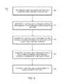
- FIG. 6is a flow diagram of an embodiment of a process for controlling lighting fixtures.
- a powerline communication control system 10 for LED lighting fixturesincludes a conventional power distribution system 12 , such as a 117 volt AC network, at least one master controller 14 and one or more LED fixture slave units 16 (three of which are diagrammatically shown in FIG. 1 but it is to be appreciated that the amount of the slave units 16 can vary depending upon the particular application).
- the control output 14 A, from each master controller 14is connected via the power distribution system 12 , so as supply a separate control input to at least one, and more preferably a plurality, of the slave unit 16
- each master controller 14receives one or more dimmer control inputs 18 A from one or more of the conventional dimmer controllers 18 .
- the dimmer controller 18may include, for example, a Digital Multiplex (DMX) controller(s), a 0-10V Dimmer(s), a TRIAC dimmer(s) or an Electronic Low Voltage (ELV) Dimmer(s) and the dimmer control inputs 18 A are conventional, standard output control signals of the corresponding types of dimmer controllers 18 . More generally, any conventional electrical controller can be accommodated by providing a suitable interface for obtaining a controller setting.
- Other controllersinclude current loop controllers as commonly used in the industrial process control of instruments. One such class of controllers is known as 4-20 mA controllers.
- the master controller 14upon receipt of the dimmer control inputs 18 A, first converts the conventional, standard control input or inputs 18 A from the one or more master controllers 18 into corresponding powerline control signals 14 A. Next, the master controller 14 imposes the powerline control signals 14 A onto the wiring of the power distribution system 12 , together with the conventional power signal 12 P present on power distribution system 12 , and also transmits the powerline control signals 14 A through the power distribution system 12 to each one of the slave units 16 .
- the powerline control signals 14 Amay be, for example, in the form of a frequency shift keyed signal (FSK), a differential frequency signal (DFSK) or a differential phase shift keyed signal (DPSK).
- the command code format of the powerline control signals 14 Amay, for example, be that of a commercially available controller format or a version thereof modified for the specific needs of a powerline communication control system 10 or may be designed specific for the powerline communication control system 10 .
- the powerline control signal 14 Amay be in the form of broadcast commands to all of the slave units 16 connected with the power distribution system 12 , so that all slave units 16 are controlled concurrently and in parallel with one another.
- the powerline control signals 14 Amay be specifically addressed to an individual slave unit 16 , or to groups of the slave units 16 , thereby allowing individualized control of one or more of the slave units 16 of the powerline communication control system 10 .
- the slave unit 16includes one or more LED lighting units 16 L (only three of which are diagrammatically shown in FIG. 1 but it is to be appreciated that the amount of the LED lighting units 16 L can vary depending upon the particular application) and a communication and power supply node 16 A.
- each communication and power supply node 16 Ahas a power and control input 16 BA, 16 BP which is connected with the power distribution system 12 in order to receive both the powerline control signals 14 A and the power signal 12 P from the power distribution system 12 .
- the communication and power supply node 16 A, of each slave unit 16initially separates the received powerline control signals 14 A from the received power signal 12 P, and then generates a DC power output 16 P from the power signal 12 P, and then supplies the generated DC power signal 16 P to the lighting units 16 L in order to power the lighting units 16 L as controlled by the master controller 14 .
- the communication and power supply node 16 A, of each slave unit 16also decodes the received powerline control signals 14 A and, in turn, then generates corresponding lighting control commands 16 C and subsequently supplies the control commands 16 C to the lighting units 16 L so as to control the operation of the lighting units 16 L.
- each master controller 14includes one or more dimmer control conversion circuits 14 B for converting the control inputs 18 A, from the corresponding dimmer controllers 18 , into the corresponding dimmer command inputs 14 C to a microprocessor 14 D which, under control of at least one program(s) residing in a resident memory (not shown for purposes of clarity) to generate the corresponding powerline control signals 14 A, which are then superimposed onto the wires of the power distribution system 12 and the power signal 12 P present thereon by a powerline interface 14 E for transmission of the slave units 16 .
- each master controller 14will also include other necessary circuitry, such as a power supply 14 F for receiving electrical power from the power distribution system 12 .
- the power and control input 16 B of each communication and power supply node 16 A of each slave unit 16includes a control input 16 BA, connected to the power distribution system 12 and to the input of a communication interface 16 B which receives the powerline control signals 14 A and the power signal 12 P from the power distribution system 12 , separates the powerline control signals 14 A from the power signal 12 P, and provides corresponding control signals 14 A to an input of a slave control microprocessor 160 .
- the slave control microprocessor 160operating under control of at least one program(s) residing in a memory (not shown for purposes of clarity), in turn, decodes control signals 14 A and generates corresponding slave control signals 16 E, which are converted into corresponding analog or digital lighting control commands 16 C, by a fixture interface 16 F, and then communicated to each one of the lighting units 16 L.
- a power input 16 BPis likewise connected to the power distribution system 12 to receive the power signal 12 with the superimposed powerline control signals 14 A and is connected to the input of a power supply 16 G which, in turn, generates DC power outputs 16 P which are supplied to the circuits of the communication and power supply node 16 A and eventually to the lighting units 16 L of the slave unit 16 .
- FIG. 4a block diagram of an alternate embodiment of the powerline communication control system 10 , according to the present invention, is shown therein.
- This embodimentas illustrated in FIG. 4 , is generally similar to the embodiments of a powerline communication control system 10 as illustrated in FIGS. 1, 2 and 3 .
- the dimmer controllers 18 and the dimmer control inputs 18 Aare replaced with a human interface controller 20 for generating human interface control inputs 20 A.
- control inputs 20 Amay be generated under the control of, for example, a knob, a slider, a keypad or some other conventional direct human input control device, thereby allowing direct human control of the slave units 16 without the associated intervention and cost of standardized, conventional dimmer controls 18 .
- FIG. 5is a functional block diagram of another embodiment of a powerline communication control system 100 for controlling lighting fixtures.
- the system 100includes a master controller, or adapter 102 , configured to interpret a response or input 103 received from a conventional controller 102 (also referred to as a legacy controller).
- a conventional controller 102also referred to as a legacy controller.
- the adapter 102includes a configurable interface 104 suitable for interconnecting to at least one of a variety of different conventional dimmer controllers.
- the adapter 102also includes a lighting control processor 106 in communication with the configurable interface 104 .
- the lighting control processor 106is adapted to generate a lighting unit command output in a lighting unit system command format in response to an input received from the conventional controller 102 .
- an input received from the controller 102provides an indication of a user-adjusted setting of the controller 102 .
- the adapter 102also includes a power distribution system interface 108 .
- the power distribution system interface 108is in communication with the lighting control processor 106 and adapted for interconnection to a power distribution system 110 .
- the power distribution system interface 108is adapted to superimpose the lighting unit system command output of the lighting control processor 106 , onto the power distribution system 110 , to all for dissemination of the lighting unit system command to one or more electrical units to be controlled.
- the adapter 102can be accommodated within a housing 112 , such as an electrical housing or box 112 adapted to accommodate a typical single or multi-gang electrical switch. Accordingly, in at least some embodiments, such an adapter 102 can be installed together with a conventional controller 102 , within a common multi-gang standard electrical box 112 .
- the box 112can be fed by an AC power feed or circuit 114 , which can be split within the box 112 (e.g., using wire connectors 116 ) to power the adapter 102 and to a second set of electrical conductors 110 providing AC facility power to the adjustable power to one or more controlled electrical devices.
- the power distribution system interface 108can be configured to convey an indication of the control setting to the one or more controlled electrical devices (e.g., lighting unit(s)) by any suitable powerline communications (PLC) protocol, such as those described herein and their equivalents.
- PLCpowerline communications
- the configurable interface 104reads an output of the conventional controller 102 .
- the configurable interface 104provides a stimulus 105 (shown in phantom) that produces a response 103 of the conventional controller 102 , suitable for determining a user-adjusted setting of the controller 102 .
- the configurable interface 104includes the one or more dimmer control conversion circuits 14 B ( FIG. 2 ).
- the lighting control processor 106e.g., the microprocessor 14 D of FIG. 2
- each conversion circuit 14 Bcan be in independently in communication with the microprocessor 14 D through a respective interface.
- the microprocessor 14 Dcan routinely monitor each of the respective inputs, for example according to a schedule, to detect changes. Upon detecting a change, the microprocessor 14 D can be configured to take a suitable action, such as generating the corresponding powerline control signals 14 A.
- the powerline communication control system 100also includes at least one device controller 120 .
- the controllercan be referred to as a powerline communication node and power supply 102 .
- the device controller 120includes a power distribution system interface 108 adapted for interconnection to the power distribution system 110 .
- the device controller 120also referred to as a command receiving interface, is further adapted to separate the lighting unit system command output from the power distribution system 110 when connected thereto.
- the device controller 120includes a powerline communication modem 122 receiving AC power including any superimposed lighting unit system command outputs.
- the powerline communication modem 122is adapted to separate the received power and command signals into a separate AC power signal and a separate lighting unit command signal.
- the device controller 120includes one or more power conversion modules 124 .
- a power conversion module 124can convert any suitable distributed power, such as AC or DC power, to any other suitable power, such as DC or AC power.
- Such power conversion modules 124are commonly referred to as one or more of power supplies, power converters, and power inverters.
- the power supply 124converts 110V AC to a DC power (e.g., 12 volts) suitable for controlling a solid state lighting unit 130 .
- any given power conversion module 124can be configured to provide more than one output (e.g., +/ ⁇ 12V, 5V, 3.3V). Such power outputs can be used to power one or more of the device controller 120 and any device modules connected thereto.
- the device controller 120includes a slave control processor 126 in communication with the command receiving interface 122 and adapted to convert the received lighting unit system command output into a corresponding lighting unit control command.
- the lighting unit control commandis forwarded to the solid state lighting unit 130 .
- the solid state lighting unit 130includes a lighting unit interface 132 adapted for interpreting the lighting unit control command and suitably driving the solid state lighting unit 130 in response to the user-adjusted setting of the interconnected one of the conventional dimmers 102 .
- the solid state lighting unit 130includes one or more LED modules or circuit boards 134 .
- Each circuit board 134can be populated with one or more lighting elements, or lamps, such as LEDs.
- One or more of the circuit board 134 and the individual LEDs, singly or in groups,can be independently addressable.
- the lighting unit system command outputscan include messages having an address portion and a command portion.
- the slave control processor 126interprets any received lighting unit system command output, for example, identifying an addressee as well as the command itself.
- the slave control processor 126converts the received lighting unit system command output into a corresponding lighting unit control command.
- the commandcan include the address, which can be interpreted to one or more interconnected lighting units 130 .
- the slave control processor 126can be preconfigured with the addresses of any interconnected lighting units 130 , selectively forwarding such messages to addressed lighting units 130 .
- a lighting unit system command outputincludes an address of the lighting unit 130 and a command to set the lighting unit 130 at an illumination level corresponding to a user-adjusted setting of the controller 102 .
- the slave control processor 126provides a suitable lighting unit control command instructing the lighting unit to illuminate at the user-desired setting.
- the lighting unit interface 132receives the command and drives the LED board(s) 134 with a corresponding current to produce the user-desired illumination.
- the lighting unit 130can remain at the desired setting until a subsequent command or instruction is received to change the illumination setting, in which instance, the lighting unit 130 will respond accordingly.
- addressesare possible, it can also be possible to provide commands without an address or with a global address, in which instance all interconnected lighting units 130 respond to the instruction. It is also possible for more than one device controller 120 to independently control the same lighting unit 130 .
- the device controller 120can receive inputs from more than one power distribution circuit 110 , or a single power distribution circuit can be interconnected to more than one device controller 120 .
- the device controller 120can simply monitor received commands without regard to their source.
- two separate controllers on a three-way controlled lighting unit 130can independently control a setting of the lighting unit, for example, according to the last command received.
- the device controller 120is configured to send commands in response to a detected change in a user-adjusted setting of an interconnected controller 102 .
- the device controller 120can be included within the lighting unit 130 .
- one or more of the power conversion module 124 and the slave control processor 126can be included in the device controller 120 , as illustrated, in the lighting unit 130 , split between the device controller 120 and lighting unit 130 , or even as separate modules.
- FIG. 6is a flow diagram of an embodiment of a process 200 for controlling lighting fixtures.
- the process 200includes determining a user-adjusted setting of a conventional dimmer controller at 205 .
- a lighting unit command outputis generated at 210 , responsive to the determined user-adjusted setting.
- the lighting unit command outputis distributed at 215 , through power distribution system to at least one lighting fixture.
- the lighting unit command outputis converted at 220 , into corresponding lighting unit control command at lighting fixture.
- the lighting unitis controlled at 225 , in response to user-adjusted setting.
- FIGS. 1 and 2generally show use of a hard wire connection for coupling the standardized, conventional dimmer control 18 to the dimmer control conversion circuit 14 B of the master controller 14 for supplying an input thereto, it is to be appreciated that such input signals can be supplied from the dimmer control 18 to the respective dimmer control conversion circuit 14 B via either a conventional wireless connection or via a conventional Ethernet connection. As such arrangements are conventional and well known in the art, a further detailed description concerning the same is not provided.
Landscapes
- Circuit Arrangement For Electric Light Sources In General (AREA)
Abstract
Description
Claims (5)
Priority Applications (1)
| Application Number | Priority Date | Filing Date | Title |
|---|---|---|---|
| US15/446,364US10462879B2 (en) | 2010-07-16 | 2017-03-01 | Powerline communication control of light emitting diode (LED) lighting fixtures |
Applications Claiming Priority (8)
| Application Number | Priority Date | Filing Date | Title |
|---|---|---|---|
| US36502610P | 2010-07-16 | 2010-07-16 | |
| PCT/US2011/044159WO2012009622A2 (en) | 2010-07-16 | 2011-07-15 | Powerline communication control of light emitting diode (led) lighting fixtures |
| US13/336,299US8410630B2 (en) | 2010-07-16 | 2011-12-23 | Powerline communication control of light emitting diode (LED) lighting fixtures |
| US13/781,003US8759999B2 (en) | 2010-07-16 | 2013-02-28 | Powerline communication control of light emitting diode (LED) lighting fixtures |
| US14/292,083US9024464B2 (en) | 2010-07-16 | 2014-05-30 | Powerline communication control of light emitting diode (LED) lighting fixtures |
| US14/675,905US9307619B2 (en) | 2010-07-16 | 2015-04-01 | Powerline communication control of light emitting diode (LED) lighting fixtures |
| US15/053,432US9622329B2 (en) | 2010-07-16 | 2016-02-25 | Powerline communication control of light emitting diode (LED) lighting fixtures |
| US15/446,364US10462879B2 (en) | 2010-07-16 | 2017-03-01 | Powerline communication control of light emitting diode (LED) lighting fixtures |
Related Parent Applications (1)
| Application Number | Title | Priority Date | Filing Date |
|---|---|---|---|
| US15/053,432ContinuationUS9622329B2 (en) | 2010-07-16 | 2016-02-25 | Powerline communication control of light emitting diode (LED) lighting fixtures |
Publications (2)
| Publication Number | Publication Date |
|---|---|
| US20170171947A1 US20170171947A1 (en) | 2017-06-15 |
| US10462879B2true US10462879B2 (en) | 2019-10-29 |
Family
ID=48669735
Family Applications (6)
| Application Number | Title | Priority Date | Filing Date |
|---|---|---|---|
| US13/336,299ActiveUS8410630B2 (en) | 2010-07-16 | 2011-12-23 | Powerline communication control of light emitting diode (LED) lighting fixtures |
| US13/781,003ActiveUS8759999B2 (en) | 2010-07-16 | 2013-02-28 | Powerline communication control of light emitting diode (LED) lighting fixtures |
| US14/292,083ActiveUS9024464B2 (en) | 2010-07-16 | 2014-05-30 | Powerline communication control of light emitting diode (LED) lighting fixtures |
| US14/675,905ActiveUS9307619B2 (en) | 2010-07-16 | 2015-04-01 | Powerline communication control of light emitting diode (LED) lighting fixtures |
| US15/053,432ActiveUS9622329B2 (en) | 2010-07-16 | 2016-02-25 | Powerline communication control of light emitting diode (LED) lighting fixtures |
| US15/446,364ActiveUS10462879B2 (en) | 2010-07-16 | 2017-03-01 | Powerline communication control of light emitting diode (LED) lighting fixtures |
Family Applications Before (5)
| Application Number | Title | Priority Date | Filing Date |
|---|---|---|---|
| US13/336,299ActiveUS8410630B2 (en) | 2010-07-16 | 2011-12-23 | Powerline communication control of light emitting diode (LED) lighting fixtures |
| US13/781,003ActiveUS8759999B2 (en) | 2010-07-16 | 2013-02-28 | Powerline communication control of light emitting diode (LED) lighting fixtures |
| US14/292,083ActiveUS9024464B2 (en) | 2010-07-16 | 2014-05-30 | Powerline communication control of light emitting diode (LED) lighting fixtures |
| US14/675,905ActiveUS9307619B2 (en) | 2010-07-16 | 2015-04-01 | Powerline communication control of light emitting diode (LED) lighting fixtures |
| US15/053,432ActiveUS9622329B2 (en) | 2010-07-16 | 2016-02-25 | Powerline communication control of light emitting diode (LED) lighting fixtures |
Country Status (6)
| Country | Link |
|---|---|
| US (6) | US8410630B2 (en) |
| EP (2) | EP2796007B1 (en) |
| AU (2) | AU2012355627B2 (en) |
| ES (1) | ES2895823T3 (en) |
| SG (2) | SG11201403529QA (en) |
| WO (1) | WO2013096063A1 (en) |
Cited By (2)
| Publication number | Priority date | Publication date | Assignee | Title |
|---|---|---|---|---|
| US11778715B2 (en) | 2020-12-23 | 2023-10-03 | Lmpg Inc. | Apparatus and method for powerline communication control of electrical devices |
| RU2804930C1 (en)* | 2023-03-22 | 2023-10-09 | Общество с ограниченной ответственностью "ЭНЕРГО-АРСЕНАЛ" | Lighting control system |
Families Citing this family (40)
| Publication number | Priority date | Publication date | Assignee | Title |
|---|---|---|---|---|
| US8410630B2 (en) | 2010-07-16 | 2013-04-02 | Lumenpulse Lighting Inc. | Powerline communication control of light emitting diode (LED) lighting fixtures |
| US9055620B1 (en)* | 2011-01-19 | 2015-06-09 | Cirrus Logic, Inc. | Consolidation of lamp power conversion and external communication control |
| US9736911B2 (en) | 2012-01-17 | 2017-08-15 | Lutron Electronics Co. Inc. | Digital load control system providing power and communication via existing power wiring |
| WO2013110024A1 (en)* | 2012-01-20 | 2013-07-25 | Osram Sylvania Inc. | Lighting driver having multiple dimming interfaces |
| CA2864464C (en) | 2012-02-15 | 2018-07-31 | Lumenpulse Lighting Inc. | Led lighting systems |
| US8768493B2 (en)* | 2012-04-25 | 2014-07-01 | Lumenpulse Lighting Inc. | Power line light controller system and method |
| JP6133412B2 (en)* | 2012-06-07 | 2017-05-24 | フィリップス ライティング ホールディング ビー ヴィ | Emergency lighting system and method |
| US9160414B2 (en)* | 2012-09-28 | 2015-10-13 | Osram Sylvania Inc. | Transient power communication |
| US9392675B2 (en) | 2013-03-14 | 2016-07-12 | Lutron Electronics Co., Inc. | Digital load control system providing power and communication via existing power wiring |
| US9521733B2 (en)* | 2013-03-27 | 2016-12-13 | Schreder | Dual-mode luminaire controllers |
| US10455654B1 (en)* | 2014-05-28 | 2019-10-22 | Cooper Technologies Company | Distributed low voltage power systems |
| US9647459B2 (en)* | 2014-05-28 | 2017-05-09 | Cooper Technologies Company | Distributed low voltage power systems |
| DE102014222231A1 (en)* | 2014-10-30 | 2016-05-04 | Tridonic Gmbh & Co Kg | Modular operating device for bulbs |
| DE102015211454A1 (en)* | 2015-06-22 | 2016-12-22 | Tridonic Gmbh & Co Kg | Sensor supply with a constant current converter for lamps |
| US20170126421A1 (en) | 2015-10-29 | 2017-05-04 | Not for Radio, LLC | Fixture data over powerline network |
| DE202016101382U1 (en)* | 2016-03-11 | 2017-06-13 | Appel-Elektronik Gmbh | lighting device |
| ITUA20163024A1 (en)* | 2016-04-29 | 2017-10-29 | St Microelectronics Srl | SEMICONDUCTOR DEVICE AND CORRESPONDING DEBUGGING PROCEDURE |
| JP2019525536A (en) | 2016-06-22 | 2019-09-05 | ソラア インコーポレーテッドSoraa Inc. | Intelligent module for intelligent network |
| US11394426B2 (en) | 2016-06-22 | 2022-07-19 | Korrus, Inc. | Intelligent modules for intelligent networks |
| US9900963B1 (en) | 2016-10-14 | 2018-02-20 | Contemporary Communications, Inc. | Lighting controller |
| US10122412B2 (en) | 2017-01-30 | 2018-11-06 | Abl Ip Holding, Llc | Power line communication system and method of auto-commissioning system nodes |
| WO2018141016A1 (en)* | 2017-02-01 | 2018-08-09 | Lionel James Barden | Improvements to monitoring and control of remote lighting sites |
| CN206640830U (en)* | 2017-02-17 | 2017-11-14 | 翰力斯有限公司 | A control system for indoor power line transmission |
| US10477650B2 (en)* | 2017-03-06 | 2019-11-12 | Usai, Llc | Digital lighting control method and system |
| US11037426B2 (en) | 2017-03-07 | 2021-06-15 | Ge-Hitachi Nuclear Energy Americas Llc | Systems and methods for combined lighting and radiation detection |
| US10455658B2 (en)* | 2017-08-23 | 2019-10-22 | Usai, Llc | Multi-mode lighting system and method |
| US10667358B1 (en)* | 2018-03-13 | 2020-05-26 | Keith Bernard Marx | Load control using AC signalling with unique signatures |
| US20190313513A1 (en)* | 2018-04-04 | 2019-10-10 | Tom Somodi | Modular LED Driving System for Architectural and Entertainment Lighting Systems |
| EP3815470B1 (en)* | 2018-06-26 | 2022-02-23 | Signify Holding B.V. | A system for configuring a lighting device |
| US11191136B2 (en) | 2018-07-16 | 2021-11-30 | Jiaxing Super Lighting Electric Appliance Co., Ltd. | LED lighting system, apparatus, and dimming method |
| US11071178B2 (en) | 2018-07-16 | 2021-07-20 | Jiaxing Super Lighting Electric Appliance Co., Ltd. | LED lighting system, apparatus, and dimming method |
| US11051386B2 (en)* | 2018-09-06 | 2021-06-29 | Lsi Industries, Inc. | Distributed intelligent network-based lighting system |
| CN110996595B (en)* | 2019-03-05 | 2021-12-24 | 联正电子(深圳)有限公司 | Integrated power distribution module and integrated power distribution monitoring system |
| EP3800792B1 (en)* | 2019-10-02 | 2022-08-03 | Zumtobel Lighting GmbH | Communication adaptor for a light trunking system, light trunking system comprising at least two such communication adaptors, and method for communicating data over such a light trunking system |
| DE102019127766B4 (en) | 2019-10-15 | 2024-01-11 | Britze Electronic Gmbh | LED lighting system |
| US12192028B2 (en)* | 2021-05-19 | 2025-01-07 | Focus Universal Inc. | System and method for a smart home system |
| WO2021158752A1 (en)* | 2020-02-05 | 2021-08-12 | Energy Focus, Inc. | Control circuit for tubular light emitting diode |
| CN212970197U (en)* | 2020-08-07 | 2021-04-13 | 漳州立达信光电子科技有限公司 | Dimmer detection circuit, light source driving circuit and lamp |
| US12096536B2 (en)* | 2022-02-02 | 2024-09-17 | Sealite Usa Llc | Powerline communications for lighting systems |
| US12089316B1 (en)* | 2023-12-14 | 2024-09-10 | Jiangmen Jinglian Technology Development Co., Ltd. | PLC signal control lamp system with adaptive power supply |
Citations (50)
| Publication number | Priority date | Publication date | Assignee | Title |
|---|---|---|---|---|
| US4815106A (en) | 1986-04-16 | 1989-03-21 | Adaptive Networks, Inc. | Power line communication apparatus |
| US4889999A (en) | 1988-09-26 | 1989-12-26 | Lutron Electronics Co., Inc. | Master electrical load control system |
| US5260974A (en) | 1991-05-10 | 1993-11-09 | Echelon Corporation | Adaptive carrier detection |
| US5455490A (en) | 1984-08-15 | 1995-10-03 | Callahan; Michael | Power and signal distribution in lighting systems |
| US5668446A (en) | 1995-01-17 | 1997-09-16 | Negawatt Technologies Inc. | Energy management control system for fluorescent lighting |
| US5828293A (en) | 1997-06-10 | 1998-10-27 | Northern Telecom Limited | Data transmission over a power line communications system |
| GB2335334A (en) | 1998-03-13 | 1999-09-15 | And Software Limited | Transmitting data over low voltage power distribution system |
| US20020065583A1 (en) | 2000-11-30 | 2002-05-30 | Matsushita Electric Works, Ltd. | Setting apparatus and setting method each for setting setting information in electric power line carrier communication terminal apparatus |
| US20020163316A1 (en) | 1997-08-26 | 2002-11-07 | Lys Ihor A. | Methods and apparatus for sensor responsive illumination of liquids |
| US20030146715A1 (en) | 2002-02-01 | 2003-08-07 | Suomi Eric W. | Extraction of accessory power from a signal supplied to a luminaire from a phase angle dimmer |
| US6664745B2 (en) | 1999-09-10 | 2003-12-16 | Richard S. Belliveau | Apparatus for digital communications with multiparameter light fixtures |
| EP1460775A1 (en) | 2003-03-18 | 2004-09-22 | Magnetek S.p.A. | Lighting control with power line modem |
| US20040225811A1 (en) | 2001-04-04 | 2004-11-11 | Fosler Ross M. | Digital addressable lighting interface bridge |
| US6867558B2 (en) | 2003-05-12 | 2005-03-15 | General Electric Company | Method and apparatus for networked lighting system control |
| US20050225976A1 (en) | 2004-04-08 | 2005-10-13 | Integrated Illumination Systems, Inc. | Marine LED lighting network and driver |
| US20060170376A1 (en) | 2005-01-24 | 2006-08-03 | Color Kinetics Incorporated | Methods and apparatus for providing workspace lighting and facilitating workspace customization |
| US20060274540A1 (en) | 2005-06-01 | 2006-12-07 | Johnson Controls Technology Company | Lighting system |
| US20070057641A1 (en) | 2005-09-09 | 2007-03-15 | Control4 Corporation | Device and method for dimming service loads |
| US7230522B2 (en) | 2004-05-06 | 2007-06-12 | Stevens Carlile R | Power line communication device and method |
| US20070233323A1 (en) | 2006-04-04 | 2007-10-04 | Panduit Corp. | Building automation system controller |
| US20070247089A1 (en) | 2004-07-15 | 2007-10-25 | E Light Limited | Lighting system and controller |
| US7307542B1 (en) | 2003-09-03 | 2007-12-11 | Vantage Controls, Inc. | System and method for commissioning addressable lighting systems |
| US20080150450A1 (en) | 2006-12-21 | 2008-06-26 | Texas Instruments Inc | Systems and methods for led based lighting |
| US20080157939A1 (en) | 2006-12-29 | 2008-07-03 | Sehat Sutardja | Power control device |
| US20080224636A1 (en) | 2007-03-12 | 2008-09-18 | Melanson John L | Power control system for current regulated light sources |
| US7456588B2 (en) | 2006-06-05 | 2008-11-25 | Osram Sylvania Inc. | Arrangement and method for providing power line communication from an AC power source to a circuit for powering a load, and electronic ballasts therefor |
| US20080297065A1 (en) | 2007-06-01 | 2008-12-04 | Honeywell International Inc. | Dual mode searchlight dimming controller systems and methods |
| WO2009013656A1 (en) | 2007-07-06 | 2009-01-29 | Koninklijke Philips Electronics N.V. | Universal dimming method and system |
| JP2009054987A (en) | 2007-08-27 | 2009-03-12 | Topco Innovation Co Ltd | Light emitting diode light source and light emitting diode lamp |
| US20090171510A1 (en) | 2008-01-02 | 2009-07-02 | Intematix Technology Center Corp. | Method and system for controlling led with power line carrier |
| US20090184662A1 (en) | 2008-01-23 | 2009-07-23 | Cree Led Lighting Solutions, Inc. | Dimming signal generation and methods of generating dimming signals |
| AU2009200556A1 (en) | 2008-02-17 | 2009-09-03 | Vukcevic, Rajko Mr | Electric Power Distribution System incorporating current multiplying DC-DC converters |
| WO2009133489A1 (en) | 2008-04-30 | 2009-11-05 | Koninklijke Philips Electronics N.V. | Methods and apparatus for encoding information on an a.c. line voltage |
| US20100090607A1 (en) | 2008-06-12 | 2010-04-15 | 3M Innovative Properties Company | Dimmer and illumination apparatus with amplitude ordered illumination of multiple strings of multiple color light emitting devices |
| US20100102747A1 (en) | 2008-10-28 | 2010-04-29 | General Electric Company | Unified 0-10v and dali dimming interface circuit |
| US20100141169A1 (en) | 2007-03-30 | 2010-06-10 | Holdip Limited | Lighting systems |
| US20100176733A1 (en) | 2009-01-14 | 2010-07-15 | Purespectrum, Inc. | Automated Dimming Methods and Systems For Lighting |
| US7865252B2 (en) | 2007-01-26 | 2011-01-04 | Autani Corporation | Upgradeable automation devices, systems, architectures, and methods |
| US20110032085A1 (en) | 2009-08-07 | 2011-02-10 | General Electric Company | Apparatus for controlling integrated lighting ballasts in a series scheme |
| US20110050132A1 (en) | 2008-05-07 | 2011-03-03 | Koninklijke Philips Electronics N.V. | Area based lighting control system including local luminaire control |
| US20110050113A1 (en) | 2008-02-15 | 2011-03-03 | Eldolab Holding B.V. | Illumination System Comprising A Light Source And A Control Unit And An Illumination Control System For Controlling A Light Source By Multiple User Interface Surfaces |
| US20110121754A1 (en) | 2006-01-20 | 2011-05-26 | Exclara Inc. | Adaptive Current Regulation for Solid State Lighting |
| US20110140611A1 (en) | 2009-12-10 | 2011-06-16 | General Electric Company | Dimming bridge module |
| US20110187275A1 (en) | 2010-02-04 | 2011-08-04 | Ywire Technologies Inc. | Lighting control switch apparatus and system |
| US20110204820A1 (en) | 2008-09-18 | 2011-08-25 | E Craftsmen Corporation | Configurable led driver/dimmer for solid state lighting applications |
| WO2011121011A1 (en) | 2010-04-01 | 2011-10-06 | Tridonic Gmbh & Co Kg | System-voltage transmission branch of an interface of an operating device for light-emitting means |
| US20110276193A1 (en) | 2010-05-04 | 2011-11-10 | Green Ballast Inc. | Energy efficient lighting system |
| US20110291583A1 (en) | 2010-06-01 | 2011-12-01 | Feng-Min Shen | Dimmer circuit applicable for led device and control method thereof |
| WO2012009622A2 (en) | 2010-07-16 | 2012-01-19 | Lumenpulse Lighting Inc. | Powerline communication control of light emitting diode (led) lighting fixtures |
| US20120133298A1 (en) | 2010-07-16 | 2012-05-31 | Lumenpulse Lighting Inc. | Powerline communication control of light emitting diode (led) lighting fixtures |
Family Cites Families (8)
| Publication number | Priority date | Publication date | Assignee | Title |
|---|---|---|---|---|
| DE10315554B3 (en) | 2003-04-05 | 2004-08-19 | Theben Ag | Dimmer module for lighting installation with programmable microprocessor control device and power stage connected in parallel with power stage of master dimmer |
| DE102006062751B4 (en) | 2006-07-21 | 2013-09-12 | Abb Ag | Multidimmer, which can be used universally as a master dimmer, as a slave dimmer or as an extension |
| US7816803B1 (en)* | 2007-08-30 | 2010-10-19 | Marvell International Ltd. | Power line control system |
| US7990082B2 (en) | 2007-10-16 | 2011-08-02 | Robert Dilley | Methods and systems for operating and controlling theatrical lighting |
| WO2011081633A1 (en) | 2009-12-31 | 2011-07-07 | Samir Gandhi | Control system for color lights |
| TWM403173U (en) | 2010-10-21 | 2011-05-01 | Semisilicon Technology Corp | Driving apparatus for LED curtain light |
| WO2013110024A1 (en)* | 2012-01-20 | 2013-07-25 | Osram Sylvania Inc. | Lighting driver having multiple dimming interfaces |
| US8768493B2 (en)* | 2012-04-25 | 2014-07-01 | Lumenpulse Lighting Inc. | Power line light controller system and method |
- 2011
- 2011-12-23USUS13/336,299patent/US8410630B2/enactiveActive
- 2012
- 2012-12-12ESES18179874Tpatent/ES2895823T3/enactiveActive
- 2012-12-12WOPCT/US2012/069321patent/WO2013096063A1/enunknown
- 2012-12-12EPEP12806309.6Apatent/EP2796007B1/enactiveActive
- 2012-12-12AUAU2012355627Apatent/AU2012355627B2/enactiveActive
- 2012-12-12SGSG11201403529QApatent/SG11201403529QA/enunknown
- 2012-12-12EPEP18179874.5Apatent/EP3399846B1/enactiveActive
- 2012-12-12SGSG10201602388PApatent/SG10201602388PA/enunknown
- 2013
- 2013-02-28USUS13/781,003patent/US8759999B2/enactiveActive
- 2014
- 2014-05-30USUS14/292,083patent/US9024464B2/enactiveActive
- 2015
- 2015-04-01USUS14/675,905patent/US9307619B2/enactiveActive
- 2015-10-09AUAU2015238893Apatent/AU2015238893B2/enactiveActive
- 2016
- 2016-02-25USUS15/053,432patent/US9622329B2/enactiveActive
- 2017
- 2017-03-01USUS15/446,364patent/US10462879B2/enactiveActive
Patent Citations (53)
| Publication number | Priority date | Publication date | Assignee | Title |
|---|---|---|---|---|
| US5455490A (en) | 1984-08-15 | 1995-10-03 | Callahan; Michael | Power and signal distribution in lighting systems |
| US4815106A (en) | 1986-04-16 | 1989-03-21 | Adaptive Networks, Inc. | Power line communication apparatus |
| US4889999A (en) | 1988-09-26 | 1989-12-26 | Lutron Electronics Co., Inc. | Master electrical load control system |
| US5260974A (en) | 1991-05-10 | 1993-11-09 | Echelon Corporation | Adaptive carrier detection |
| US5668446A (en) | 1995-01-17 | 1997-09-16 | Negawatt Technologies Inc. | Energy management control system for fluorescent lighting |
| US5828293A (en) | 1997-06-10 | 1998-10-27 | Northern Telecom Limited | Data transmission over a power line communications system |
| US20020163316A1 (en) | 1997-08-26 | 2002-11-07 | Lys Ihor A. | Methods and apparatus for sensor responsive illumination of liquids |
| GB2335334A (en) | 1998-03-13 | 1999-09-15 | And Software Limited | Transmitting data over low voltage power distribution system |
| US6664745B2 (en) | 1999-09-10 | 2003-12-16 | Richard S. Belliveau | Apparatus for digital communications with multiparameter light fixtures |
| US20020065583A1 (en) | 2000-11-30 | 2002-05-30 | Matsushita Electric Works, Ltd. | Setting apparatus and setting method each for setting setting information in electric power line carrier communication terminal apparatus |
| US20040225811A1 (en) | 2001-04-04 | 2004-11-11 | Fosler Ross M. | Digital addressable lighting interface bridge |
| US20030146715A1 (en) | 2002-02-01 | 2003-08-07 | Suomi Eric W. | Extraction of accessory power from a signal supplied to a luminaire from a phase angle dimmer |
| EP1460775A1 (en) | 2003-03-18 | 2004-09-22 | Magnetek S.p.A. | Lighting control with power line modem |
| US6867558B2 (en) | 2003-05-12 | 2005-03-15 | General Electric Company | Method and apparatus for networked lighting system control |
| US7307542B1 (en) | 2003-09-03 | 2007-12-11 | Vantage Controls, Inc. | System and method for commissioning addressable lighting systems |
| US20050225976A1 (en) | 2004-04-08 | 2005-10-13 | Integrated Illumination Systems, Inc. | Marine LED lighting network and driver |
| US7230522B2 (en) | 2004-05-06 | 2007-06-12 | Stevens Carlile R | Power line communication device and method |
| US20070247089A1 (en) | 2004-07-15 | 2007-10-25 | E Light Limited | Lighting system and controller |
| US20060170376A1 (en) | 2005-01-24 | 2006-08-03 | Color Kinetics Incorporated | Methods and apparatus for providing workspace lighting and facilitating workspace customization |
| US20060274540A1 (en) | 2005-06-01 | 2006-12-07 | Johnson Controls Technology Company | Lighting system |
| US20070057641A1 (en) | 2005-09-09 | 2007-03-15 | Control4 Corporation | Device and method for dimming service loads |
| US20110121754A1 (en) | 2006-01-20 | 2011-05-26 | Exclara Inc. | Adaptive Current Regulation for Solid State Lighting |
| US20070233323A1 (en) | 2006-04-04 | 2007-10-04 | Panduit Corp. | Building automation system controller |
| US7456588B2 (en) | 2006-06-05 | 2008-11-25 | Osram Sylvania Inc. | Arrangement and method for providing power line communication from an AC power source to a circuit for powering a load, and electronic ballasts therefor |
| US20080150450A1 (en) | 2006-12-21 | 2008-06-26 | Texas Instruments Inc | Systems and methods for led based lighting |
| US20080157939A1 (en) | 2006-12-29 | 2008-07-03 | Sehat Sutardja | Power control device |
| US7865252B2 (en) | 2007-01-26 | 2011-01-04 | Autani Corporation | Upgradeable automation devices, systems, architectures, and methods |
| US20080224636A1 (en) | 2007-03-12 | 2008-09-18 | Melanson John L | Power control system for current regulated light sources |
| US20100141169A1 (en) | 2007-03-30 | 2010-06-10 | Holdip Limited | Lighting systems |
| US20080297065A1 (en) | 2007-06-01 | 2008-12-04 | Honeywell International Inc. | Dual mode searchlight dimming controller systems and methods |
| WO2009013656A1 (en) | 2007-07-06 | 2009-01-29 | Koninklijke Philips Electronics N.V. | Universal dimming method and system |
| JP2009054987A (en) | 2007-08-27 | 2009-03-12 | Topco Innovation Co Ltd | Light emitting diode light source and light emitting diode lamp |
| US20090171510A1 (en) | 2008-01-02 | 2009-07-02 | Intematix Technology Center Corp. | Method and system for controlling led with power line carrier |
| US20090184662A1 (en) | 2008-01-23 | 2009-07-23 | Cree Led Lighting Solutions, Inc. | Dimming signal generation and methods of generating dimming signals |
| US20110050113A1 (en) | 2008-02-15 | 2011-03-03 | Eldolab Holding B.V. | Illumination System Comprising A Light Source And A Control Unit And An Illumination Control System For Controlling A Light Source By Multiple User Interface Surfaces |
| AU2009200556A1 (en) | 2008-02-17 | 2009-09-03 | Vukcevic, Rajko Mr | Electric Power Distribution System incorporating current multiplying DC-DC converters |
| US20110043124A1 (en) | 2008-04-30 | 2011-02-24 | Koninklijke Philips Electronics N.V. | Methods and apparatus for encoding information on an a.c. line voltage |
| WO2009133489A1 (en) | 2008-04-30 | 2009-11-05 | Koninklijke Philips Electronics N.V. | Methods and apparatus for encoding information on an a.c. line voltage |
| US20110050132A1 (en) | 2008-05-07 | 2011-03-03 | Koninklijke Philips Electronics N.V. | Area based lighting control system including local luminaire control |
| US20100090607A1 (en) | 2008-06-12 | 2010-04-15 | 3M Innovative Properties Company | Dimmer and illumination apparatus with amplitude ordered illumination of multiple strings of multiple color light emitting devices |
| US20110204820A1 (en) | 2008-09-18 | 2011-08-25 | E Craftsmen Corporation | Configurable led driver/dimmer for solid state lighting applications |
| US20100102747A1 (en) | 2008-10-28 | 2010-04-29 | General Electric Company | Unified 0-10v and dali dimming interface circuit |
| US20100176733A1 (en) | 2009-01-14 | 2010-07-15 | Purespectrum, Inc. | Automated Dimming Methods and Systems For Lighting |
| US20110032085A1 (en) | 2009-08-07 | 2011-02-10 | General Electric Company | Apparatus for controlling integrated lighting ballasts in a series scheme |
| US20110140611A1 (en) | 2009-12-10 | 2011-06-16 | General Electric Company | Dimming bridge module |
| US20110187275A1 (en) | 2010-02-04 | 2011-08-04 | Ywire Technologies Inc. | Lighting control switch apparatus and system |
| WO2011121011A1 (en) | 2010-04-01 | 2011-10-06 | Tridonic Gmbh & Co Kg | System-voltage transmission branch of an interface of an operating device for light-emitting means |
| US20110276193A1 (en) | 2010-05-04 | 2011-11-10 | Green Ballast Inc. | Energy efficient lighting system |
| US20110291583A1 (en) | 2010-06-01 | 2011-12-01 | Feng-Min Shen | Dimmer circuit applicable for led device and control method thereof |
| WO2012009622A2 (en) | 2010-07-16 | 2012-01-19 | Lumenpulse Lighting Inc. | Powerline communication control of light emitting diode (led) lighting fixtures |
| US20120133298A1 (en) | 2010-07-16 | 2012-05-31 | Lumenpulse Lighting Inc. | Powerline communication control of light emitting diode (led) lighting fixtures |
| US8410630B2 (en) | 2010-07-16 | 2013-04-02 | Lumenpulse Lighting Inc. | Powerline communication control of light emitting diode (LED) lighting fixtures |
| US9024464B2 (en)* | 2010-07-16 | 2015-05-05 | Lumenpulse Lighting Inc. | Powerline communication control of light emitting diode (LED) lighting fixtures |
Non-Patent Citations (1)
| Title |
|---|
| Office Action from related European Application No. 12806309.6-1804 dated May 4, 2017. |
Cited By (2)
| Publication number | Priority date | Publication date | Assignee | Title |
|---|---|---|---|---|
| US11778715B2 (en) | 2020-12-23 | 2023-10-03 | Lmpg Inc. | Apparatus and method for powerline communication control of electrical devices |
| RU2804930C1 (en)* | 2023-03-22 | 2023-10-09 | Общество с ограниченной ответственностью "ЭНЕРГО-АРСЕНАЛ" | Lighting control system |
Also Published As
| Publication number | Publication date |
|---|---|
| US20120133298A1 (en) | 2012-05-31 |
| EP2796007A1 (en) | 2014-10-29 |
| US9024464B2 (en) | 2015-05-05 |
| SG11201403529QA (en) | 2014-09-26 |
| US9307619B2 (en) | 2016-04-05 |
| SG10201602388PA (en) | 2016-05-30 |
| AU2012355627B2 (en) | 2015-07-09 |
| US20150271898A1 (en) | 2015-09-24 |
| AU2015238893B2 (en) | 2017-05-25 |
| HK1203118A1 (en) | 2015-10-16 |
| EP2796007B1 (en) | 2018-06-27 |
| US20170171947A1 (en) | 2017-06-15 |
| US8410630B2 (en) | 2013-04-02 |
| EP3399846A1 (en) | 2018-11-07 |
| US8759999B2 (en) | 2014-06-24 |
| EP3399846B1 (en) | 2021-10-13 |
| US20160262244A1 (en) | 2016-09-08 |
| AU2012355627A1 (en) | 2014-07-17 |
| US20130175946A1 (en) | 2013-07-11 |
| ES2895823T3 (en) | 2022-02-22 |
| AU2015238893A1 (en) | 2015-10-29 |
| US20140346970A1 (en) | 2014-11-27 |
| US9622329B2 (en) | 2017-04-11 |
| WO2013096063A1 (en) | 2013-06-27 |
Similar Documents
| Publication | Publication Date | Title |
|---|---|---|
| US10462879B2 (en) | Powerline communication control of light emitting diode (LED) lighting fixtures | |
| US10292244B2 (en) | Communication module | |
| CN101983540B (en) | Configurable lighting fixtures under broadcast control | |
| US20090066266A1 (en) | Integrated power and control unit for a solid-state lighting device | |
| US11778715B2 (en) | Apparatus and method for powerline communication control of electrical devices | |
| CN103781227A (en) | Intelligent light-regulating LED power supply device based on DALI | |
| EP3751965A1 (en) | System for controlling a series of lighting fixtures | |
| WO2012009622A2 (en) | Powerline communication control of light emitting diode (led) lighting fixtures | |
| US11277894B2 (en) | Universal adapter for lighting system for indoor grow application | |
| JP6941804B2 (en) | Lighting equipment control device and directing lighting system | |
| CA2895706C (en) | Powerline communication control of light emitting diode (led) lighting fixtures | |
| HK1203118B (en) | Powerline communication control of light emitting diode (led) lighting fixtures | |
| JP2016181454A (en) | Lighting control system, lighting device, and lighting control method | |
| JP2016181452A (en) | Illumination control system, illumination device, and illumination control method | |
| CN215222538U (en) | Dimming lamp controller and dimming system based on PLBUS technology | |
| KR20110104136A (en) | SMPS and lighting control device for chain LED lighting | |
| EP1631126A2 (en) | Control system for illumination devices | |
| HK1167210A (en) | A method and a device for communication over load line | |
| JPH04271389A (en) | Control system for electrically decorative signboard |
Legal Events
| Date | Code | Title | Description |
|---|---|---|---|
| AS | Assignment | Owner name:LUMENPULSE GROUP INC., CANADA Free format text:AMALGAMATION;ASSIGNORS:LUMENPULSE INC.;10191051 CANADA INC.;REEL/FRAME:043164/0186 Effective date:20170621 Owner name:LUMENPULSE INC., CANADA Free format text:AMALGAMATION;ASSIGNORS:LUMENPULSE INC.;ECLAIRAGE LUMENPULSE INC.;LUMENPULSE LIGHTING INC.;REEL/FRAME:043167/0715 Effective date:20170620 | |
| AS | Assignment | Owner name:NATIONAL BANK OF CANADA, AS SECURED PARTY, CANADA Free format text:SECURITY INTEREST (SENIOR);ASSIGNOR:LUMENPULSE GROUP INC.;REEL/FRAME:043812/0491 Effective date:20170901 Owner name:NATIONAL BANK OF CANADA, AS COLLATERAL AGENT, CANA Free format text:SECURITY INTEREST (SUBORDINATED);ASSIGNOR:LUMENPULSE GROUP INC.;REEL/FRAME:043814/0235 Effective date:20170901 | |
| STPP | Information on status: patent application and granting procedure in general | Free format text:FINAL REJECTION MAILED | |
| STPP | Information on status: patent application and granting procedure in general | Free format text:NOTICE OF ALLOWANCE MAILED -- APPLICATION RECEIVED IN OFFICE OF PUBLICATIONS | |
| AS | Assignment | Owner name:LUMENPULSE LIGHTING INC., CANADA Free format text:ASSIGNMENT OF ASSIGNORS INTEREST;ASSIGNOR:CAMPBELL, GREGORY;REEL/FRAME:050220/0720 Effective date:20111222 | |
| STPP | Information on status: patent application and granting procedure in general | Free format text:PUBLICATIONS -- ISSUE FEE PAYMENT VERIFIED | |
| STCF | Information on status: patent grant | Free format text:PATENTED CASE | |
| AS | Assignment | Owner name:LMPG INC., CANADA Free format text:CERTIFICATE OF AMENDMENT;ASSIGNOR:LUMENPULSE GROUP INC.;REEL/FRAME:056273/0473 Effective date:20210503 | |
| AS | Assignment | Owner name:NATIONAL BANK OF CANADA, CANADA Free format text:SECURITY INTEREST;ASSIGNOR:LMPG INC.;REEL/FRAME:058300/0601 Effective date:20211129 | |
| MAFP | Maintenance fee payment | Free format text:PAYMENT OF MAINTENANCE FEE, 4TH YEAR, LARGE ENTITY (ORIGINAL EVENT CODE: M1551); ENTITY STATUS OF PATENT OWNER: LARGE ENTITY Year of fee payment:4 | |
| AS | Assignment | Owner name:ROYNAT CAPITAL INC., CANADA Free format text:SECURITY INTEREST;ASSIGNORS:LMPG INC.;LUMENPULSE LIGHTING CORP.;STERNBERG LANTERNS, INC.;AND OTHERS;REEL/FRAME:064009/0205 Effective date:20230608 |