US10460600B2 - Driver behavior monitoring - Google Patents
Driver behavior monitoringDownload PDFInfo
- Publication number
- US10460600B2 US10460600B2US15/437,646US201715437646AUS10460600B2US 10460600 B2US10460600 B2US 10460600B2US 201715437646 AUS201715437646 AUS 201715437646AUS 10460600 B2US10460600 B2US 10460600B2
- Authority
- US
- United States
- Prior art keywords
- visual data
- vehicle
- driver
- monitored vehicle
- data
- Prior art date
- Legal status (The legal status is an assumption and is not a legal conclusion. Google has not performed a legal analysis and makes no representation as to the accuracy of the status listed.)
- Active
Links
Images


Classifications
- G—PHYSICS
- G08—SIGNALLING
- G08G—TRAFFIC CONTROL SYSTEMS
- G08G1/00—Traffic control systems for road vehicles
- G08G1/01—Detecting movement of traffic to be counted or controlled
- G08G1/04—Detecting movement of traffic to be counted or controlled using optical or ultrasonic detectors
- G—PHYSICS
- G06—COMPUTING OR CALCULATING; COUNTING
- G06F—ELECTRIC DIGITAL DATA PROCESSING
- G06F18/00—Pattern recognition
- G06F18/20—Analysing
- G06F18/24—Classification techniques
- G06F18/241—Classification techniques relating to the classification model, e.g. parametric or non-parametric approaches
- G06F18/2413—Classification techniques relating to the classification model, e.g. parametric or non-parametric approaches based on distances to training or reference patterns
- G06F18/24133—Distances to prototypes
- G06K9/00791—
- G06K9/00845—
- G06K9/6271—
- G—PHYSICS
- G06—COMPUTING OR CALCULATING; COUNTING
- G06V—IMAGE OR VIDEO RECOGNITION OR UNDERSTANDING
- G06V10/00—Arrangements for image or video recognition or understanding
- G06V10/40—Extraction of image or video features
- G—PHYSICS
- G06—COMPUTING OR CALCULATING; COUNTING
- G06V—IMAGE OR VIDEO RECOGNITION OR UNDERSTANDING
- G06V10/00—Arrangements for image or video recognition or understanding
- G06V10/70—Arrangements for image or video recognition or understanding using pattern recognition or machine learning
- G06V10/764—Arrangements for image or video recognition or understanding using pattern recognition or machine learning using classification, e.g. of video objects
- G—PHYSICS
- G06—COMPUTING OR CALCULATING; COUNTING
- G06V—IMAGE OR VIDEO RECOGNITION OR UNDERSTANDING
- G06V10/00—Arrangements for image or video recognition or understanding
- G06V10/70—Arrangements for image or video recognition or understanding using pattern recognition or machine learning
- G06V10/82—Arrangements for image or video recognition or understanding using pattern recognition or machine learning using neural networks
- G—PHYSICS
- G06—COMPUTING OR CALCULATING; COUNTING
- G06V—IMAGE OR VIDEO RECOGNITION OR UNDERSTANDING
- G06V20/00—Scenes; Scene-specific elements
- G06V20/50—Context or environment of the image
- G06V20/56—Context or environment of the image exterior to a vehicle by using sensors mounted on the vehicle
- G06V20/58—Recognition of moving objects or obstacles, e.g. vehicles or pedestrians; Recognition of traffic objects, e.g. traffic signs, traffic lights or roads
- G—PHYSICS
- G06—COMPUTING OR CALCULATING; COUNTING
- G06V—IMAGE OR VIDEO RECOGNITION OR UNDERSTANDING
- G06V20/00—Scenes; Scene-specific elements
- G06V20/50—Context or environment of the image
- G06V20/59—Context or environment of the image inside of a vehicle, e.g. relating to seat occupancy, driver state or inner lighting conditions
- G06V20/597—Recognising the driver's state or behaviour, e.g. attention or drowsiness
- G—PHYSICS
- G07—CHECKING-DEVICES
- G07C—TIME OR ATTENDANCE REGISTERS; REGISTERING OR INDICATING THE WORKING OF MACHINES; GENERATING RANDOM NUMBERS; VOTING OR LOTTERY APPARATUS; ARRANGEMENTS, SYSTEMS OR APPARATUS FOR CHECKING NOT PROVIDED FOR ELSEWHERE
- G07C5/00—Registering or indicating the working of vehicles
- G07C5/08—Registering or indicating performance data other than driving, working, idle, or waiting time, with or without registering driving, working, idle or waiting time
- G07C5/0808—Diagnosing performance data
- G—PHYSICS
- G07—CHECKING-DEVICES
- G07C—TIME OR ATTENDANCE REGISTERS; REGISTERING OR INDICATING THE WORKING OF MACHINES; GENERATING RANDOM NUMBERS; VOTING OR LOTTERY APPARATUS; ARRANGEMENTS, SYSTEMS OR APPARATUS FOR CHECKING NOT PROVIDED FOR ELSEWHERE
- G07C5/00—Registering or indicating the working of vehicles
- G07C5/08—Registering or indicating performance data other than driving, working, idle, or waiting time, with or without registering driving, working, idle or waiting time
- G07C5/0841—Registering performance data
- G07C5/085—Registering performance data using electronic data carriers
- G07C5/0866—Registering performance data using electronic data carriers the electronic data carrier being a digital video recorder in combination with video camera
- G—PHYSICS
- G08—SIGNALLING
- G08G—TRAFFIC CONTROL SYSTEMS
- G08G1/00—Traffic control systems for road vehicles
- G08G1/01—Detecting movement of traffic to be counted or controlled
- G08G1/0104—Measuring and analyzing of parameters relative to traffic conditions
- G08G1/0108—Measuring and analyzing of parameters relative to traffic conditions based on the source of data
- G08G1/0112—Measuring and analyzing of parameters relative to traffic conditions based on the source of data from the vehicle, e.g. floating car data [FCD]
- G—PHYSICS
- G08—SIGNALLING
- G08G—TRAFFIC CONTROL SYSTEMS
- G08G1/00—Traffic control systems for road vehicles
- G08G1/01—Detecting movement of traffic to be counted or controlled
- G08G1/0104—Measuring and analyzing of parameters relative to traffic conditions
- G08G1/0125—Traffic data processing
- G08G1/0129—Traffic data processing for creating historical data or processing based on historical data
- G—PHYSICS
- G08—SIGNALLING
- G08G—TRAFFIC CONTROL SYSTEMS
- G08G1/00—Traffic control systems for road vehicles
- G08G1/01—Detecting movement of traffic to be counted or controlled
- G08G1/0104—Measuring and analyzing of parameters relative to traffic conditions
- G08G1/0125—Traffic data processing
- G08G1/0133—Traffic data processing for classifying traffic situation
- G—PHYSICS
- G08—SIGNALLING
- G08G—TRAFFIC CONTROL SYSTEMS
- G08G1/00—Traffic control systems for road vehicles
- G08G1/01—Detecting movement of traffic to be counted or controlled
- G08G1/0104—Measuring and analyzing of parameters relative to traffic conditions
- G08G1/0137—Measuring and analyzing of parameters relative to traffic conditions for specific applications
- G—PHYSICS
- G08—SIGNALLING
- G08G—TRAFFIC CONTROL SYSTEMS
- G08G1/00—Traffic control systems for road vehicles
- G08G1/01—Detecting movement of traffic to be counted or controlled
- G08G1/015—Detecting movement of traffic to be counted or controlled with provision for distinguishing between two or more types of vehicles, e.g. between motor-cars and cycles
- G—PHYSICS
- G08—SIGNALLING
- G08G—TRAFFIC CONTROL SYSTEMS
- G08G1/00—Traffic control systems for road vehicles
- G08G1/01—Detecting movement of traffic to be counted or controlled
- G08G1/052—Detecting movement of traffic to be counted or controlled with provision for determining speed or overspeed
- B—PERFORMING OPERATIONS; TRANSPORTING
- B60—VEHICLES IN GENERAL
- B60W—CONJOINT CONTROL OF VEHICLE SUB-UNITS OF DIFFERENT TYPE OR DIFFERENT FUNCTION; CONTROL SYSTEMS SPECIALLY ADAPTED FOR HYBRID VEHICLES; ROAD VEHICLE DRIVE CONTROL SYSTEMS FOR PURPOSES NOT RELATED TO THE CONTROL OF A PARTICULAR SUB-UNIT
- B60W2420/00—Indexing codes relating to the type of sensors based on the principle of their operation
- B60W2420/40—Photo, light or radio wave sensitive means, e.g. infrared sensors
- B60W2420/403—Image sensing, e.g. optical camera
- B60W2420/42—
- B—PERFORMING OPERATIONS; TRANSPORTING
- B60—VEHICLES IN GENERAL
- B60W—CONJOINT CONTROL OF VEHICLE SUB-UNITS OF DIFFERENT TYPE OR DIFFERENT FUNCTION; CONTROL SYSTEMS SPECIALLY ADAPTED FOR HYBRID VEHICLES; ROAD VEHICLE DRIVE CONTROL SYSTEMS FOR PURPOSES NOT RELATED TO THE CONTROL OF A PARTICULAR SUB-UNIT
- B60W40/00—Estimation or calculation of non-directly measurable driving parameters for road vehicle drive control systems not related to the control of a particular sub unit, e.g. by using mathematical models
- B60W40/08—Estimation or calculation of non-directly measurable driving parameters for road vehicle drive control systems not related to the control of a particular sub unit, e.g. by using mathematical models related to drivers or passengers
- B60W40/09—Driving style or behaviour
- G—PHYSICS
- G06—COMPUTING OR CALCULATING; COUNTING
- G06Q—INFORMATION AND COMMUNICATION TECHNOLOGY [ICT] SPECIALLY ADAPTED FOR ADMINISTRATIVE, COMMERCIAL, FINANCIAL, MANAGERIAL OR SUPERVISORY PURPOSES; SYSTEMS OR METHODS SPECIALLY ADAPTED FOR ADMINISTRATIVE, COMMERCIAL, FINANCIAL, MANAGERIAL OR SUPERVISORY PURPOSES, NOT OTHERWISE PROVIDED FOR
- G06Q40/00—Finance; Insurance; Tax strategies; Processing of corporate or income taxes
- G06Q40/08—Insurance
- G—PHYSICS
- G06—COMPUTING OR CALCULATING; COUNTING
- G06V—IMAGE OR VIDEO RECOGNITION OR UNDERSTANDING
- G06V20/00—Scenes; Scene-specific elements
- G06V20/40—Scenes; Scene-specific elements in video content
- G06V20/44—Event detection
Definitions
- Certain aspects of the present disclosuregenerally relate to internet-of-things (IOT) devices and applications, and more particularly, to devices, systems and methods for transmitting a descriptor of an event, as may be used, for example, in monitoring a behavior of drivers, in unsupervised learning of action values, and in monitoring an environment of a vehicle.
- IOTinternet-of-things
- Vehiclessuch as automobiles, trucks, tractors, motorcycles, bicycles, airplanes, drones, ships, boats, submarines, and others, are typically operated and controlled by human drivers.
- a human drivermay learn how to drive a vehicle safely and efficiently in a range of conditions or contexts. For example, as an automobile driver gains experience, he may become adept at driving in challenging conditions such as rain, snow, or darkness.
- Unsafe driving behaviormay endanger the driver and other drivers and may risk damaging the vehicle. Unsafe driving behaviors may also lead to fines. For example, highway patrol officers may issue a citation for speeding. Unsafe driving behavior may also lead to accidents, which may cause physical harm, and which may, in turn, lead to an increase in insurance rates for operating a vehicle. Inefficient driving, which may include hard accelerations, may increase the costs associated with operating a vehicle.
- Driving behaviormay be monitored.
- Driver monitoringmay be done in real-time as the driver operates a vehicle, or may be done at a later time based on recorded data.
- Driver monitoring at a later timemay be useful, for example, when investigating the cause of an accident.
- Driver monitoring in real-timemay be useful to guard against unsafe driving, for example, by ensuring that a car cannot exceed a certain pre-determined speed.
- driver monitoring devicesmay process inertial sensor data, speedometer data, GPS data, and the like
- visual datasuch as camera data
- Vehicle monitoring devicespresent other technical hurdles in addition to challenges associated with video transmission and storage.
- Certain aspects of the present disclosuregenerally relate to providing, implementing, and using a method of transmitting a descriptor of an event.
- monitoring systemsmay log data relating to a visual scene.
- an enabled systemmay classify a driver behavior, such as by characterizing the behavior as “good” or “bad”.
- monitoring and/or characterization of driver behaviorsmay be automated.
- certain aspects of the present disclosuremay enable a context-sensitive classification of driver behavior.
- the present disclosurealso provides systems and methods for unsupervised learning of action values, monitoring of a driver's environment, and transmitting visual data and/or descriptors of visual data from a client to a server.
- Certain aspects of the present disclosureprovide a method of transmitting a descriptor of an event.
- the methodgenerally includes receiving visual data from a first camera at a first device; detecting the event based at least in part on the visual data and a first inference engine; determining the descriptor of the event; and transmitting a first data comprising the descriptor from the first device to a second device.
- the apparatusgenerally includes a first memory unit; a second memory unit; a first at least one processor coupled to the first memory unit; and a second at least one processor coupled to the first memory unit; in which the first at least one processor is configured to: receive visual data from a first camera; detect the event based at least in part on the visual data and a first inference engine; determine the descriptor of the event; and transmit a first data comprising the descriptor from the first device to the second memory unit.
- the apparatusgenerally includes means for receiving visual data from a first camera at a first device; means for detecting the event based at least in part on the visual data and a first inference engine; means for determining the descriptor of the event; and means for transmitting a first data comprising the descriptor from the first device to a second device
- Certain aspects of the present disclosureprovide a non-transitory computer-readable medium having program code recorded thereon for transmitting a descriptor of an event.
- the program codeis executed by a processor and generally comprises program code to: receive visual data from a first camera; detect an event based at least in part on the visual data and a first inference engine; determine the descriptor of the event; and transmit a first data comprising the descriptor to a second device.
- Certain aspects of the present disclosureprovide a method of monitoring a driver behavior.
- the methodgenerally includes receiving visual data from a camera at a first device; wherein the camera is affixed to a first vehicle; and wherein the first device is connected to the camera; determining a classification of a driving behavior based at least in part on the visual data and an inference engine; and transmitting the classification to a second device.
- the apparatusgenerally includes a first memory unit; a second memory unit; a first at least one processor coupled to the first memory unit; and a second at least one processor coupled to the first memory unit; in which the first at least one processor is configured to: receive visual data from a camera at a first device; wherein the camera is affixed to a first vehicle; and wherein the first device is connected to the camera; determine a classification of a driving behavior based at least in part on the visual data and an inference engine; and transmit the classification to a second device.
- the apparatusgenerally includes means for receiving visual data from a camera at a first device; wherein the camera is affixed to a first vehicle; and wherein the first device is connected to the camera; means for determining a classification of a driving behavior based at least in part on the visual data and an inference engine; and means for transmitting the classification to a second device.
- Certain aspects of the present disclosureprovide a non-transitory computer-readable medium having program code recorded thereon for monitoring a driver behavior.
- the program codeis executed by a processor and generally comprises program code to: receive visual data from a camera at a first device; wherein the camera is affixed to a first vehicle; and wherein the first device is connected to the camera; determine a classification of a driving behavior based at least in part on the visual data and an inference engine; and transmit the classification to a second device.
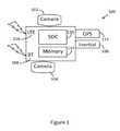
- FIG. 1illustrates an example of a device for transmitting a descriptor of an event in accordance with certain aspects of the present disclosure.
- FIG. 2illustrates an example of a driver monitoring system in accordance with certain aspects of the present disclosure.
- FIG. 3illustrates the use of global positioning information to determine a driving behavior.
- Driver monitoring systems and devicesmay have multiple applications. Insurance companies may desire aggregated driver behavior data to influence premiums. Insurance companies may also seek to reward ‘good’ behavior and dis-incentivize ‘bad’ behavior as a way of reducing the number of loss events across a population of drivers. Fleet owners, likewise, might desire a system capable of classifying driver behaviors as a part of a program to incentivize their drivers to drive safely and efficiently. Likewise, taxi aggregators may desire a driver monitoring systems as part of a program to incentivize taxi driver behavior. Furthermore, taxi or ride-sharing aggregator customers may desire access to past characterizations of driver behavior so that they may filter and select drivers based on driver behavior criteria. For example, to ensure safety, drivers of children or other vulnerable populations might be screened based on driving behavior exhibited in the past. Parents may desire to monitor the driving patterns of their kids and may further utilize methods of monitoring and characterizing driver behavior to incentivize safe driving behavior.
- Self-driving carsmay include a machine controller (which may be referred to as a computerized driving controller) that interprets sensory inputs and issues control signals to the car so that the car may be driven without a human driver or with minimal human intervention.
- machine controllersmay also exhibit unsafe or inefficient driving behaviors.
- Information relating to the driving behavior of a self-driving carmay be of interest to engineers attempting to improve a self-driving car's controller, to law-makers considering policies relating to self-driving cars, and to other interested parties.
- a driver monitoring systemmay be based on sensor data available in at an ODB-II port, which may not include vision data.
- a driver monitoring systemmay rely on inertial and/or odometer data to monitor a driver.
- Such a driver monitoring systemmay be used to maintain a desired driving behavior and/or limit an undesired behavior, but may do so in a way that does not depend on the context of the driving behavior.
- a new drivermay be limited to driving below a certain speed based on odometer measurements. Limiting the speed of a car for a new driver, however, may have unintended negative consequences. For example, if the driver is blocking an ambulance on a narrow road, the driver may be unable to overcome the speed settings and may block the ambulance.
- driver monitoring systemsmay detect driving events based on non-visual sensors, but may further include a vision sensor to capture visual data around the time of a detected event.
- a driver monitoring systemmay process inertial sensor data to detect undesired driving behaviors.
- An inertial eventmay be an event with a detectable signature on a trace of accelerometer or gyrometer data, such a transient spike in an accelerometer trace corresponding to a sudden stop by a vehicle.
- commercial-grade inertial sensorsmay be noisy, however, such a system may falsely detect irrelevant inertial events (which may be referred to as “false alarms”) that have a similar accelerometer trace but that may not correspond to a driving event of interest. For example, running over a pothole or a speed-bump may have an accelerometer reading that is similar to that of a small collision.
- an inertial sensor-based systemmay record a video clip upon detecting an inertial event, and then the video clip may be reviewed by a human operator at a later time. Due to the involvement of the human operator, such as system may be expensive and cumbersome.
- an inertial-triggered driver monitoring systemmay fail to notice a driving event that does not have a reliably detectable inertial signature. For example, an inertial-based system with a camera may fail to detect a driver running through a red light if the driver neither accelerated or decelerated through the red light.
- Certain aspects of the present disclosuremay enable the use of visual data in IOT systems and devices, such as driver behavior monitoring systems.
- Visual datamay improve existing ways or enable new ways of monitoring and characterizing driver behavior.
- visual data captured at a camera affixed to a vehiclemay be used as the basis for detecting a driving event.
- a driver monitoring system enabled in accordance with certain aspects of the present disclosuremay detect that a driver has run a red light, even if the event could not be reliably detected from inertial sensor data and/or GPS data.
- a first devicemay be configured to analyze visual data to detect an object.
- An object detectionmay refer to producing bounding boxes and object identifiers that correspond to one or more relevant objects in a scene. In a driver monitoring system, for example, it may be desirable to produce bounding boxes surrounding all or most of the visible cars, as well as visible traffic lights, traffic signs, and the like.
- a first devicemay be configured to detect (locate and identify) a traffic light in visual data across multiple frames, including frames in which only a portion of a traffic light may be visible in the field of view of a camera. The event of running a red-light may then be based on a location of the detected traffic light and its state (such as green or red).
- four of the five numbersmay indicate the coordinates of the detected object (for example, the horizontal and vertical coordinates of a top-left corner of a bounding box surrounding the object, and a height and a width of the bounding box), and one number indicating the class to which it belonged (for example, the cars may be identified with a “1” and the traffic light may be identified with a “3”).
- the output of a neural networkmay account for a calibration of a camera and may, instead of (or in addition to) representing a location of an object in coordinates of a visual field, represent the location of the objects as a distance from the camera (which may further include an angle and an indication of size).
- objectsmay be identified as having a distance relative to a specified point that is not the camera, such as the front bumper of a car.
- the class identification datamay include a probability of the object belonging to one or more classes, and/or may include a portion of visual data associated with the bounding box.
- visual informationmay be used to classify a behavior in a context-sensitive manner.
- running a red-lighttypically, running a red light may be considered a ‘bad’ driving behavior.
- a ‘bad’ driving behaviorsuch as tailgating, may not be the fault of the driver. For example, another driver may have pulled into the driver's lane at an unsafe distance ahead of the driver.
- monitoring a driver behaviormay include collecting measurements relating to the movements of a vehicle in relation to lane markings on a road, in relation other vehicles, and/or in relation to other objects such as traffic officers, traffic signals, signs, and the like.
- a classification of a driving behaviormay be based on one or more measurements determined at a first device connected to a vision sensor that is affixed to a vehicle.
- multiple measurementsmay be produced by a first inference engine running at a specialized hardware accelerator connected to a camera, as described above.
- the measurementsmay then be transmitted from the first device and received at a second device, where a number of measurements may be processed by a second inference engine.
- the second inference enginemay be a neural network that is trained to classify a driving behavior based on measurements from the first inference engine.
- FIG. 1illustrates an embodiment of the aforementioned devices, systems and methods for transmitting a descriptor of an event.
- the device 100may include input sensors (which may include a forward facing camera 102 , a driver facing camera 104 , connections to other cameras that are not physically mounted to the device, inertial sensors 106 , car OBD-II port sensor data (which may be obtained through a Bluetooth connection 108 ), and the like) and compute capability 110 .
- the compute capabilitymay be a CPU or an integrated System-on-a-chip (SOC), which may include a CPU and other specialized compute cores, such as a graphics processor (GPU), gesture recognition processor, and the like.
- SOCSystem-on-a-chip
- a driver monitoring systemmay assess the driver's behavior in real-time.
- an in-car monitoring systemsuch as the device 100 illustrated in FIG. 1 that may be mounted to a car, may perform analysis in support of a driver behavior assessment in real-time.
- real-time analysismay refer to a configuration in which visual data is processed at a rate that meets or exceeds the rate that it is captured.
- real-time analysismay refer to a configuration in which at least a sampling of the visual data is processed on a device connected to the corresponding camera soon after it is recorded.
- the driver monitoring systemin comparison with a system that does not include real-time processing, may avoid storing large amounts of sensor data since it may instead store a processed and reduced set of the data. Similarly, or in addition, because the system may transmit a reduced set of data (for example, descriptors of objects that are detected in the visual data), rather than the visual data itself, the system may incur fewer costs associated with wirelessly transmitting data to a remote server.
- a reduced set of datafor example, descriptors of objects that are detected in the visual data
- Such a systemmay still be configured to upload video data that is determined to be salient for some purpose.
- the memory capacity corresponding to three hours of high-definition video datamay instead be used to store multiple days of descriptor data alone with a reduced set of salient video data.
- Such a systemmay be less likely to be affected by wireless coverage issues because the memory storage may be sufficient to store data until the truck is again in a location with satisfactory cellular coverage, or until the truck encounters a Wi-Fi access point.
- a driver monitoring systemmay assess a driver's behavior in multiple contexts.
- a driver behaviormay be scored using more than one metric.
- FIG. 2illustrates a system of driver monitoring in accordance with certain aspects of the present disclosure.
- the systemmay include sensors 210 , profiles 230 , sensory recognition and monitoring modules 240 , assessment modules 260 , and may produce an overall grade 280 .
- Contemplated driver assessment modulesinclude speed assessment 262 , safe following distance 264 , obeying traffic signs and lights 266 , safe lane changes and lane position 268 , hard accelerations including turns 270 , responding to traffic officers, responding to road conditions 272 , and responding to emergency vehicles.
- a driver monitoring systemmay be directed to assessing whether the driver is maintaining a safe speed 262 , which may be based on traffic conditions, weather conditions, visibility, and the like.
- a driver monitoring systemmay read speed limit signs 244 using visual input 212 from a camera.
- the systemmay determine the car's speed 246 using one or more outputs of sensors 210 or sensor monitoring modules 240 , including GPS 222 , car speedometer 220 (using either an OBD-II type interface 226 or a visual camera reading of the dash), and/or visual speed assessment based on detected and computed relative motion of outside objects 256 (such as stationary sign posts).
- a driver assessment module 260may then assess whether the driver is maintaining (or has maintained if the module is run at a later time) a safe speed 262 by computing a function of the two speeds, namely the posted speed limit 244 and the current speed of the driver 246 .
- an assessment of driver speed 262may be reduced to a grade, or score.
- the gradingmay include determining (a) if the driver is over the speed limit, (b) if the driver is over the speed limit by various amounts, (c) how much the driver is over the speed limit, or (d) a function of the difference of the two speeds.
- a functionmay include legally defined traffic fine step points.
- a driver monitoring systemmay also include a determination of the driver's speed relative to speeds of other cars on the road 248 .
- the grade of the drivermay be based on the driver's speed 246 relative to the speeds of other cars 248 , as well as the posted speed limit (which may be recognized by a traffic lights and signs recognition module 244 ).
- the drivermay be graded negatively for going too slow or too fast.
- the driver grademay be more favorable if the driver is driving over the speed limit at a time when a determined percentage of other cars are also going approximately the same speed.
- a driver monitoring systemmay determine recommended speeds from signs 244 , such as signs placed near curves or in other caution areas.
- an assessment modulemay adjust the driver's grade as a function of the driver's speed and the recommended speed. For example, the driver grade for safe speed behavior may improve if the driver's speed is below the recommended speed in a given caution area, as well as below the legal speed limit of the road.
- a driver monitoring systemmay determine based on visible signage 244 and other scene identifiers that may be recognized 242 that the car is in a safety sensitive area, such as a construction zone, school zone, day-time headlights required zone, and the like.
- an assessment module 262may adjust the grade for safe speed behavior based on the recognition of the safety sensitive area. For example, the driver grade for safe speed behavior may improve if the driver's speed 246 is substantially below the speed limit in these zones (based on visible signage 244 ), even if the flow of traffic 248 is above the speed limit.
- the contribution to the grade for safe speed behaviormay be weighted higher for these more sensitive zones and weighted relatively lower for less safety sensitive areas.
- visual 212 or inertial sensors 218may be used to determine if the vehicle is on an incline, and furthermore, whether it is traveling uphill or downhill. This determination may be added as an input to an assessment module for grading driver speed 262 . For example, since a vehicle may have more problems stopping when going down a steep decline, the grading may reflect that traveling above the speed limit in these situations may have a more detrimental effect on the grade compared to travelling above the speed limit on a flat highway.
- a driver monitoring systemmay be configured to detect and classify the type of vehicle being driven.
- the systemmay estimate the type of vehicle.
- the systemmay use the information about the type of vehicle 234 to select the relevant speed limit signs 244 on roads with different speeds for different vehicle types. For example, a road may have a posted 55 MPH speed limit for trucks and a 65 MPH speed limit for cars.
- a driver monitoring systemmay also use context to infer speed limits. For example, speed limits may be inferred on roads without marked speed limits or when a driver enters a road and speed limit signs have not yet been observed.
- a visual scene identification module 242may determine that the road is a residential road and the GPS 222 may further indicate the locality. Based on these, the legal residential speed limit, such as 25 miles per hour (MPH), may be applied.
- MPHmiles per hour
- the scene detection module 242observes a school area and children present, the system may determine based on the output from the scene detection module 242 that the area is a school zone with the corresponding speed limit. The grading may be applied based on these estimated or inferred speed limits and the vehicle's measured speed 246 .
- a grading assessment for driver speed 262may also be weighted based on the method used to determine the speed limit. For example, the contribution to the grade for safe speed behavior may be weighted lower when there is low certainty from the scene identification module 242 .
- a grading assessmentmay also provide more granular feedback to the user by, for example, breaking out grades associated with different detected scenes (based on the output from a scene recognition module 242 ). That may help educate drivers as to whether they are adjusting their behavior according to different driving situations.
- a driver monitoring systemmay process stored data at a later time, in accordance with aspects of the present disclosure. For example, the system may keep track of the driver's speed 246 over time and then use an observed speed limit sign 244 to apply the speed limit over the recent past. In this example, the system may use visual 212 , inertial 218 , GPS 22 , map, or other indications to determine the length of time that that the car has been on the same street and under the same driving conditions so that the observed speed limit would apply.
- aspects of the present disclosureare directed to visually measuring the following distance 264 , which is the distance to the vehicle directly in front of the driver's car.
- a mono-camera 102may be used to identify the type of vehicle being followed, such as a sedan, van, or semi-truck.
- the following distancemay be based on feature sizes, such as width, or the relative feature sizes of multiple features associated with each type of vehicle.
- a machine learning modelsuch as a deep neural network, may be used to determine the distance based on the input pixels corresponding to the vehicle ahead. While the preceding examples utilize a mono-camera, the present disclosure is not so limiting.
- other sensorssuch as RADAR, Ultrasound (SONAR), or LIDAR, may be used to determine the distance to the vehicle ahead.
- multiple methodsmay be combined to estimate the distance.
- the visual system 212may also be used to help determine the car's velocity 246 and either alone or in conjunction with inertial sensors 218 and/or GPS 222 may determine whether and where the car came to a complete stop. For example, GPS error rates may make it difficult to assess whether the car stopped before or on the railroad tracks when waiting for a traffic light, while a visual road object recognition system 256 may more accurately make that determination.
- the driver monitoring systemmay track lane markings 250 or estimate lane separations, determine the car's position with respect to the lane markings, and assess the extent to which the driver maintains a safe lane position. For example, a driver may be graded up (or positively) for maintaining a center location, and may me graded down (or negatively) for getting too close to lane edges or crossing over lane edges outside of the context of a lane change.
- an accelerometer 218may be used to detect freeway rumble ridges, infer crossing into the shoulder, and based on the detected rumble ridges, the driver's behavior may be graded down.
- a driver monitoring systemmay assess the driver's behavior with respect to fuel inefficient maneuvers, such as hard starts or hard accelerations 270 .
- An assessment module 260may include an assessment of acceleration 270 , which may be based on a measurement of the rate of acceleration 252 using one or more of visual 212 , GPS 222 , inertial sensors 218 , or car speedometer 220 .
- the acceleration assessment module 270in accordance with certain aspects of the aforementioned systems and methods of classifying a driving behavior, may have a threshold on the amount of acceleration and may note a violation. Alternatively, or in addition, the module may note a series of gradations of acceleration behavior.
- the driver's situational responsivenesscould be inferred based on audio input 214 .
- road noisemay be used to determine traffic conditions and/or the presence of honked horns.
- multiple microphones with beam-formingmay be used to help localize the direction to the emergency vehicle, car, or train horn.
- a driver's gradewhich may be based on the aggregated descriptors, may be plotted over time.
- the driver gradesmay also be averaged to determine a score per time period, such as per hour, day, week, month, or year.
- the averagingmay be an equal weighted arithmetic average, or it may be some other averaging over time.
- the gradingmay include different weightings for the assessments of different types of driving behavior features 260 , for example, an assessment of merging safely 268 may be weighted higher than an assessment of hard starts 270 .
- the methods of grading particular behaviorsmay be modified based on driving conditions.
- the weightings of different driving behavior assessmentsmay vary based on a recognized context such as a combination of road conditions, traffic 248 , and other recognized features of the environment 242 .
- the weighting over time of safe speed behaviormay be higher for riskier environments, so that the contribution of the driver's speed behavior 262 to the overall grade 280 will be higher at these times.
- riskier environmentsmay include construction areas, poor weather conditions (such as snow), or poor visibility (such as fog).
- the weather conditionsmay be determined based on visual inference 212 , from an atmospheric sensor 216 , from a cloud service accessed via LTE 224 , or a combination thereof.
- descriptors of events in visual data and/or classifications of driving behaviorsmay be computed or stored for averaging over specified contexts, such as environments, areas, or times.
- the driver's grade 280may be based on behaviors that were monitored while the driver was in school zones, as determined by a scene recognition module 242 .
- the resolution of a picture or video clipmay be adjusted based on wireless bandwidth considerations.
- the amount of data transferred between the client and the cloudmay be adjusted based on the ratio of a remaining bandwidth in a monthly bandwidth allocation to the size of the monthly bandwidth allocation. In this example, if the ratio is high, then a high-resolution video clip recorded around the time of an event may be sent to the could for further processing. If the remaining bandwidth drops, the video resolution, and hence the video size, may be reduced for the current data transfer and/or for future data transfers in the same month.
- the systemmay assign separate grading scores for different events.
- the systemmay separate the grading of driver behavior into first, identifying ‘unsafe’ events, and second, determining whether the driver is responsible for those events.
- the systemmay determine responsibility by computing as estimate of driver fault based on a trained machine-learning model.
- a driver grading systemmay assign scores using a reinforcement learning approach.
- the machine learningmay be implemented using a Deep Neural Network, Support Vector Machine (SVM), or some combination thereof.
- Inputs to the machine learning systemmay be feature vectors over N frames, such as the last N frames prior to the detection of an unsafe event.
- the inputs to the machine learning algorithmmay be time stepped by M frames such that if at t0 the inputs are feature vectors from frames 0 . . . N, then at t1, the inputs are from M . . . N+M, and so on.
- a feature vectorcould include a car speed, a lane position, the relative position of other cars, and/or the relative position or distance to pedestrians.
- the speed and/or other data for the feature vectormay be obtained from the OBD-II port.
- the feature vectormay also include GPS data.
- the amount of data transfer from the client to the cloudmay be adjusted differently in response to bandwidth considerations based on the type of event being communicated.
- the thresholds at which different types of events are communicated to the cloudmay be adjusted differently.
- the adjustment of the amount of data transfermay be done in such as way that some event types stop reporting for the remainder of a month. For example, if the bandwidth usage ratio reaches 80%, speed limit violations may stop being reported, although hard stop events may continue to be reported. There may also be some events that continue to be reported even after the monthly limit is exceeded; for example, if a collision is detected the video clip around the collision may be sent even though the data transfer would exceed the allocated limit and may incur additional transmission costs.
- events that are not transmitted in real-time or near real-timemay be cached and transmitted later over a different link, such as Wi-Fi, or at a different time, such as the beginning of the next month.
- the cached event transmissionsmay be limited to a certain usage of the next month's bandwidth allocation. For example, the first 10% of cached events may be transmitted at the start of a new month.
- the set of cached eventsmay be graded and ranked, and the most severe events may be transmitted.
- this approachmay be used for managing the memory usage of cached event clips and data if memory storage on the device 114 nears full capacity.
- Visual indications of stationary objectsmay also be crowd sourced via the cloud, in accordance with aspects of the present disclosure.
- carsmay send their GPS coordinates to the cloud via wireless connectivity such as LTE 110 at points where they detect a change in the road characterization 242 , such as a change of speed limit or start of a construction zone.
- the cloudmay keep track of different road segments, and may provide this information to other driver monitoring systems.
- the driver monitoring systemmay periodically report the car's position to the cloud service, and the service may send back its estimate of the road features that the car should expect to observe. This may increase robustness of road feature detection. For example, it may decrease the uncertainty associated with detecting and/or recognizing traffic signs that are obscured by other vehicles. It may also increase robustness of the sensory recognition systems in night-time versus day-time lighting.
- the crowd sourced systemmay also reduce classification errors overall.
- a focal zonemay be defined based on the measured speed of the vehicle 246 .
- a focal zonemay be an area of interest of the visual scene in which objects that may interact with the vehicle in the near term are likely to be found based on the speed of the vehicle.
- a focal zonemay also refer to a range of scales in multi-resolution processing. For example, if the vehicle is traveling at slow speeds, the focal zone may be configured to search for pedestrians that would be closer than 150 feet.
- the previous exampleis directed to limiting a visual search to just searching one zone, other means for increasing computational efficiency are contemplated.
- there could be several focal zonesfor example a near focal zone, medium distance focal zone, and a far focal zone.
- different focal zonescould be associated with different priorities, and the different focal zones may be processed with different levels of computational complexity. For example, higher priority focal zones may be searched at a higher frequency compared with lower priority zones. Alternatively, or in addition, higher priority focal zones may have more complex and accurate search models than lower priority zones. Alternatively, or in addition, higher priority zones may be searched at a finer window step size than lower priority zones.
- the lower priority zonesmay be the portions of the image and image resolutions that are not identified as high priority focal zones.
- the visual system 212 and grading systems 260 and 280may be trained end-to-end. Rather than training the visual system for cars 248 , pedestrians, lanes 250 , distances, and so forth, and then a system on top to match grading scores 260 , the system may be trained end-to-end such that grading scores 260 are computed directly from sensory data 210 . Still, the training procedure may start with training certain subsystems 240 independently, and then performing full end-to-end training on a combination of subsystems 240 and sensory inputs 210 , such as by back propagation. This training procedure may result in the detection of more fine-tuned visual features which may be the basis for more accurate driver assessment scores 260 .
- a driving behaviormay be classified directly based at least in part on visual data from the camera.
- This configurationcontrasts with some exemplary embodiments described above that may first detect an event and determine a descriptor of the event at a first device, then transmit the descriptor to a second device where it may be used to classify a driving behavior. Instead, in some embodiments, the step of determining a descriptor may be skipped.
- a cameramay be affixed to a vehicle, and a device may be attached to the camera through a shared memory, a wired connection, a wireless connection such as Bluetooth, and the like.
- a split systemmay achieve a desired classification performance based on less training data in comparison an end-to-end system.
- a split systemmay be include separate modules, each of which may detect events relating on one aspect of driving behavior. For example, one module may detect other cars or trucks on the road, while a second module may detect traffic lights. In some embodiments, these two modules may share some common processing steps, such as a common trunk of a deep learning network.
- Each of these modulesmay be trained with a number of examples covering a variety of relevant objects that might be encountered. For example, a car and truck detecting inference engine may be trained on labeled car and truck data.
- an end-to-end systemmay be considered to achieve a desired classification performance after it may reliably classify driving behavior as safe or unsafe. Relevant training data (such as sensor data corresponding to unsafe driving scenarios) may be less frequently encountered in comparison to, for example, visual data containing other cars or trucks. For this reason, an end-to-end inference engine may be more challenging to train.
- a crowd sourced reinforcement learning approachmay be used.
- the driver monitoring systemmay crowd source issued traffic infractions across drivers, and use those to label unsafe or inappropriate driving actions.
- the visual systemmay also identify police cars.
- a reinforcement learning rulemay use training examples in which drivers were near police cars. The learning rule may be based on rewarding the driver behaviors for which the drivers did not receive an infraction, and penalizing the driver behaviors for which the drivers did receive an infraction.
- the sensor data preceding the accidentmay be used as an input to a reinforcement learning rule to adjust the grading system inference engine.
- the infractions, traffic accidents, and the likemay be used as a supervisory signal and crowd sourced to train an inference engine that outputs an estimate of the probability of a traffic accident or infraction based on the input sensor data.
- An updated modelmay be pushed out periodically to the driver monitor systems to improve the quality of the systems.
- the updated modelmay be used to update or replace an inference engine on the device.
- an enabled deviceConfigured with an updated inference engine, an enabled device may exhibit improve driver behavior monitoring. For example, it may subsequently upload a higher ratio of relevant to irrelevant video clips to a cloud server.
- the driver monitor systemmay also utilize a prediction engine to forecast different paths that the driver could take or could have taken in a given situation, and compute the infraction and/or accident probabilities along those paths, and then score the driver based on the path taken compared with the other paths. The score may be compared with the best path, the top percentile best path, the average path, or other measures.
- crowd sourced driver statisticsmay be used to determine safe and typical behaviors.
- driver behaviormay be assessed based on these determined safe and typical behaviors.
- the driver behavior distributionsmay be determined for different maneuvers and events.
- Statistical analysis or machine learning methodsmay be used based on the determined driver behavior distributions to determine driver grades.
- the lane position for a drivermay be measured across drivers, either in general or based on scene recognition determined similar contexts, such as United States freeways.
- the distribution of the lane positionsmay then be formed with the mean and standard deviation computed, and the driver grade may be a function of the standard deviation and mean or median, such as the number of standard deviations away from the mean.
- a value closer to the meanmay be graded higher while a value farther from the mean would be graded lower.
- the grademay be scaled by the standard deviation of the distribution of lane positions across drivers in a similar context.
- the distribution of lane changes or freeway merge temporal pathsmay be computed across drivers. Then the grade may be based on a deviation from typical paths.
- the paths across driversmay have grades assigned based on how close they come to another vehicle. In these examples, the driver's path may be compared against a dictionary of paths aggregated across multiple drivers and a grade may be assigned based on the typical outcome of drivers with similar paths.
- crowd-sourced datamay include descriptors of events or objects detected by a number of devices.
- a deviceconfigured according to certain aspects of the present disclosure may transmit data relating to a car's lane position to a second device.
- the second devicemay be a cloud server.
- the cloud servermay also interact with other similarly configured devices from other cars and may thereby receive data regarding lane positions, for example, from a sample of cars on the road.
- the second devicemay create an inference engine. For example, it may train a neural network to detect abnormal lane positions, where a cluster of received lane position data may be used to determine what a normal lane position could be.
- an inference engine determined at a second devicemay learn that some abnormal lane positions are actually characteristic of safe or responsive driving.
- the second devicemay have trained a reinforcement learning model that may output a safe or unsafe action based on visual data, and an inferred action of the driver may be compared to the output of the model.
- the reinforcement learning modelmay output a description of a visual scene corresponding to a safe action being taken in response to a first description of the visual scene.
- the reinforcement learning modelmay be based on a sequence of previously detected objects that were detected in visual data by a deployed device.
- determiningencompasses a wide variety of actions. For example, “determining” may include calculating, computing, processing, deriving, investigating, looking up (e.g., looking up in a table, a database or another data structure), ascertaining and the like. Additionally, “determining” may include receiving (e.g., receiving information), accessing (e.g., accessing data in a memory) and the like. Furthermore, “determining” may include resolving, selecting, choosing, establishing and the like.
- certain aspectsmay comprise a computer program product for performing the operations presented herein.
- a computer program productmay comprise a computer-readable medium having instructions stored (and/or encoded) thereon, the instructions being executable by one or more processors to perform the operations described herein.
- the computer program productmay include packaging material.
- modules and/or other appropriate means for performing the methods and techniques described hereincan be downloaded and/or otherwise obtained by a user terminal and/or base station as applicable.
- a user terminal and/or base stationcan be coupled to a server to facilitate the transfer of means for performing the methods described herein.
- various methods described hereincan be provided via storage means (e.g., RAM, ROM, a physical storage medium such as a compact disc (CD) or floppy disk, etc.), such that a user terminal and/or base station can obtain the various methods upon coupling or providing the storage means to the device.
- storage meanse.g., RAM, ROM, a physical storage medium such as a compact disc (CD) or floppy disk, etc.
- CDcompact disc
- floppy disketc.
- any other suitable technique for providing the methods and techniques described herein to a devicecan be utilized.
Landscapes
- Engineering & Computer Science (AREA)
- Physics & Mathematics (AREA)
- General Physics & Mathematics (AREA)
- Theoretical Computer Science (AREA)
- Multimedia (AREA)
- Analytical Chemistry (AREA)
- Chemical & Material Sciences (AREA)
- Evolutionary Computation (AREA)
- Computer Vision & Pattern Recognition (AREA)
- Artificial Intelligence (AREA)
- Medical Informatics (AREA)
- General Health & Medical Sciences (AREA)
- Databases & Information Systems (AREA)
- Software Systems (AREA)
- Health & Medical Sciences (AREA)
- Computing Systems (AREA)
- Data Mining & Analysis (AREA)
- General Engineering & Computer Science (AREA)
- Evolutionary Biology (AREA)
- Bioinformatics & Computational Biology (AREA)
- Bioinformatics & Cheminformatics (AREA)
- Life Sciences & Earth Sciences (AREA)
- Traffic Control Systems (AREA)
- Automation & Control Theory (AREA)
- Mathematical Physics (AREA)
- Transportation (AREA)
- Mechanical Engineering (AREA)
Abstract
Description
Claims (26)
Priority Applications (6)
| Application Number | Priority Date | Filing Date | Title |
|---|---|---|---|
| US15/437,646US10460600B2 (en) | 2016-01-11 | 2017-02-21 | Driver behavior monitoring |
| US16/507,894US11024165B2 (en) | 2016-01-11 | 2019-07-10 | Driver behavior monitoring |
| US16/704,520US11113961B2 (en) | 2016-01-11 | 2019-12-05 | Driver behavior monitoring |
| US16/725,763US11074813B2 (en) | 2016-01-11 | 2019-12-23 | Driver behavior monitoring |
| US17/330,635US11990036B2 (en) | 2016-01-11 | 2021-05-26 | Driver behavior monitoring |
| US18/659,547US12406576B2 (en) | 2016-01-11 | 2024-05-09 | Driver behavior monitoring |
Applications Claiming Priority (3)
| Application Number | Priority Date | Filing Date | Title |
|---|---|---|---|
| US201662277470P | 2016-01-11 | 2016-01-11 | |
| PCT/US2017/013062WO2017123665A1 (en) | 2016-01-11 | 2017-01-11 | Driver behavior monitoring |
| US15/437,646US10460600B2 (en) | 2016-01-11 | 2017-02-21 | Driver behavior monitoring |
Related Parent Applications (1)
| Application Number | Title | Priority Date | Filing Date |
|---|---|---|---|
| PCT/US2017/013062ContinuationWO2017123665A1 (en) | 2016-01-11 | 2017-01-11 | Driver behavior monitoring |
Related Child Applications (1)
| Application Number | Title | Priority Date | Filing Date |
|---|---|---|---|
| US16/507,894ContinuationUS11024165B2 (en) | 2016-01-11 | 2019-07-10 | Driver behavior monitoring |
Publications (2)
| Publication Number | Publication Date |
|---|---|
| US20170200061A1 US20170200061A1 (en) | 2017-07-13 |
| US10460600B2true US10460600B2 (en) | 2019-10-29 |
Family
ID=59276202
Family Applications (5)
| Application Number | Title | Priority Date | Filing Date |
|---|---|---|---|
| US15/437,646ActiveUS10460600B2 (en) | 2016-01-11 | 2017-02-21 | Driver behavior monitoring |
| US16/507,894ActiveUS11024165B2 (en) | 2016-01-11 | 2019-07-10 | Driver behavior monitoring |
| US16/704,520ActiveUS11113961B2 (en) | 2016-01-11 | 2019-12-05 | Driver behavior monitoring |
| US16/725,763ActiveUS11074813B2 (en) | 2016-01-11 | 2019-12-23 | Driver behavior monitoring |
| US17/330,635Active2037-11-09US11990036B2 (en) | 2016-01-11 | 2021-05-26 | Driver behavior monitoring |
Family Applications After (4)
| Application Number | Title | Priority Date | Filing Date |
|---|---|---|---|
| US16/507,894ActiveUS11024165B2 (en) | 2016-01-11 | 2019-07-10 | Driver behavior monitoring |
| US16/704,520ActiveUS11113961B2 (en) | 2016-01-11 | 2019-12-05 | Driver behavior monitoring |
| US16/725,763ActiveUS11074813B2 (en) | 2016-01-11 | 2019-12-23 | Driver behavior monitoring |
| US17/330,635Active2037-11-09US11990036B2 (en) | 2016-01-11 | 2021-05-26 | Driver behavior monitoring |
Country Status (1)
| Country | Link |
|---|---|
| US (5) | US10460600B2 (en) |
Cited By (40)
| Publication number | Priority date | Publication date | Assignee | Title |
|---|---|---|---|---|
| US20190311226A1 (en)* | 2018-04-10 | 2019-10-10 | Pony.ai, Inc. | Enhanced training information generation |
| CN113012431A (en)* | 2021-02-25 | 2021-06-22 | 青岛海信网络科技股份有限公司 | Method and device for detecting highway traffic incident |
| WO2021138341A1 (en)* | 2019-12-31 | 2021-07-08 | Beijing Didi Infinity Technology And Development Co., Ltd. | Pattern-based adaptation model for detecting contact information requests in a vehicle |
| US20210206315A1 (en)* | 2018-05-15 | 2021-07-08 | Robert Bosch Gmbh | Ecu and lane departure warning system |
| US20210331668A1 (en)* | 2020-04-28 | 2021-10-28 | Microsoft Technology Licensing, Llc | Drive safety forecast for future drives |
| US11238319B2 (en)* | 2019-03-14 | 2022-02-01 | Visteon Global Technologies, Inc. | Method and control unit for detecting a region of interest |
| US11250335B2 (en)* | 2015-10-26 | 2022-02-15 | NetraDyne, Inc. | Joint processing for embedded data inference |
| US11330399B2 (en) | 2020-04-28 | 2022-05-10 | Microsoft Technology Licensing, Llc | Anomaly predictor for physical safety of group members |
| US11370446B2 (en)* | 2018-08-06 | 2022-06-28 | Honda Motor Co., Ltd. | System and method for learning and predicting naturalistic driving behavior |
| US11495028B2 (en)* | 2018-09-28 | 2022-11-08 | Intel Corporation | Obstacle analyzer, vehicle control system, and methods thereof |
| US11529950B2 (en)* | 2018-04-10 | 2022-12-20 | Pony Ai Inc. | Enhanced training information generation |
| US11584379B2 (en)* | 2018-08-06 | 2023-02-21 | Honda Motor Co., Ltd. | System and method for learning naturalistic driving behavior based on vehicle dynamic data |
| US11620987B2 (en) | 2019-12-31 | 2023-04-04 | Beijing Didi Infinity Technology And Development Co., Ltd. | Generation of training data for verbal harassment detection |
| US11664043B2 (en) | 2019-12-31 | 2023-05-30 | Beijing Didi Infinity Technology And Development Co., Ltd. | Real-time verbal harassment detection system |
| US11670286B2 (en) | 2019-12-31 | 2023-06-06 | Beijing Didi Infinity Technology And Development Co., Ltd. | Training mechanism of verbal harassment detection systems |
| US12106613B2 (en) | 2020-11-13 | 2024-10-01 | Samsara Inc. | Dynamic delivery of vehicle event data |
| US12117546B1 (en) | 2020-03-18 | 2024-10-15 | Samsara Inc. | Systems and methods of remote object tracking |
| US12126917B1 (en) | 2021-05-10 | 2024-10-22 | Samsara Inc. | Dual-stream video management |
| US12128919B2 (en) | 2020-11-23 | 2024-10-29 | Samsara Inc. | Dash cam with artificial intelligence safety event detection |
| US12137143B1 (en) | 2019-04-26 | 2024-11-05 | Samsara Inc. | Event detection system |
| US12140445B1 (en) | 2020-12-18 | 2024-11-12 | Samsara Inc. | Vehicle gateway device and interactive map graphical user interfaces associated therewith |
| US12150186B1 (en) | 2024-04-08 | 2024-11-19 | Samsara Inc. | Connection throttling in a low power physical asset tracking system |
| US12165336B1 (en) | 2019-04-26 | 2024-12-10 | Samsara Inc. | Machine-learned model based event detection |
| US12168445B1 (en) | 2020-11-13 | 2024-12-17 | Samsara Inc. | Refining event triggers using machine learning model feedback |
| US12172653B1 (en) | 2021-01-28 | 2024-12-24 | Samsara Inc. | Vehicle gateway device and interactive cohort graphical user interfaces associated therewith |
| US12179629B1 (en) | 2020-05-01 | 2024-12-31 | Samsara Inc. | Estimated state of charge determination |
| US12197610B2 (en) | 2022-06-16 | 2025-01-14 | Samsara Inc. | Data privacy in driver monitoring system |
| US12213090B1 (en) | 2021-05-03 | 2025-01-28 | Samsara Inc. | Low power mode for cloud-connected on-vehicle gateway device |
| US12228944B1 (en) | 2022-04-15 | 2025-02-18 | Samsara Inc. | Refining issue detection across a fleet of physical assets |
| US12260616B1 (en) | 2024-06-14 | 2025-03-25 | Samsara Inc. | Multi-task machine learning model for event detection |
| US12269498B1 (en) | 2022-09-21 | 2025-04-08 | Samsara Inc. | Vehicle speed management |
| US12289181B1 (en) | 2020-05-01 | 2025-04-29 | Samsara Inc. | Vehicle gateway device and interactive graphical user interfaces associated therewith |
| US12306010B1 (en) | 2022-09-21 | 2025-05-20 | Samsara Inc. | Resolving inconsistencies in vehicle guidance maps |
| US12327445B1 (en) | 2024-04-02 | 2025-06-10 | Samsara Inc. | Artificial intelligence inspection assistant |
| US12344168B1 (en) | 2022-09-27 | 2025-07-01 | Samsara Inc. | Systems and methods for dashcam installation |
| US12346712B1 (en) | 2024-04-02 | 2025-07-01 | Samsara Inc. | Artificial intelligence application assistant |
| US12375578B1 (en) | 2020-02-20 | 2025-07-29 | Samsara Inc. | Device arrangement for deriving a communication data scheme |
| US12391256B1 (en)* | 2019-04-26 | 2025-08-19 | Samsara Inc. | Baseline event detection system |
| US12426007B1 (en) | 2022-04-29 | 2025-09-23 | Samsara Inc. | Power optimized geolocation |
| US12445285B1 (en) | 2022-09-28 | 2025-10-14 | Samsara Inc. | ID token monitoring system |
Families Citing this family (147)
| Publication number | Priority date | Publication date | Assignee | Title |
|---|---|---|---|---|
| US9774604B2 (en) | 2015-01-16 | 2017-09-26 | Zingbox, Ltd. | Private cloud control |
| GB201501510D0 (en)* | 2015-01-29 | 2015-03-18 | Apical Ltd | System |
| SG10201806013QA (en) | 2015-02-05 | 2018-08-30 | Uber Technologies Inc | Programmatically determining location information in connection with a transport service |
| US10212178B2 (en) | 2015-04-07 | 2019-02-19 | Zingbox, Ltd. | Packet analysis based IoT management |
| ES2984381T3 (en) | 2015-09-17 | 2024-10-29 | Cambridge Mobile Telematics Inc | Systems and methods for detecting and evaluating distracted drivers |
| US9940530B2 (en)* | 2015-12-29 | 2018-04-10 | Thunder Power New Energy Vehicle Development Company Limited | Platform for acquiring driver behavior data |
| US10460600B2 (en) | 2016-01-11 | 2019-10-29 | NetraDyne, Inc. | Driver behavior monitoring |
| WO2017123665A1 (en) | 2016-01-11 | 2017-07-20 | Netradyne Inc. | Driver behavior monitoring |
| US11691565B2 (en) | 2016-01-22 | 2023-07-04 | Cambridge Mobile Telematics Inc. | Systems and methods for sensor-based detection, alerting and modification of driving behaviors |
| US9786104B2 (en)* | 2016-01-25 | 2017-10-10 | Smartdrive Systems, Inc. | Systems and method to trigger vehicle events based on contextual information |
| WO2017154967A1 (en)* | 2016-03-11 | 2017-09-14 | 日本電気株式会社 | Abnormal travel detecting device, abnormal travel detecting method, storage medium storing program for same, and abnormal travel detecting system |
| US9928875B2 (en)* | 2016-03-22 | 2018-03-27 | Nec Corporation | Efficient video annotation with optical flow based estimation and suggestion |
| US10407078B2 (en)* | 2016-04-26 | 2019-09-10 | Sivalogeswaran Ratnasingam | Dynamic learning driving system and method |
| US11072339B2 (en)* | 2016-06-06 | 2021-07-27 | Truemotion, Inc. | Systems and methods for scoring driving trips |
| WO2017218585A1 (en) | 2016-06-13 | 2017-12-21 | Surround.IO Corporation | Method and system for providing auto space management using virtuous cycle |
| WO2018009567A1 (en) | 2016-07-05 | 2018-01-11 | Nauto Global Limited | System and method for automatic driver identification |
| US10832331B1 (en)* | 2016-07-11 | 2020-11-10 | State Farm Mutual Automobile Insurance Company | Systems and methods for allocating fault to autonomous vehicles |
| US11322018B2 (en) | 2016-07-31 | 2022-05-03 | NetraDyne, Inc. | Determining causation of traffic events and encouraging good driving behavior |
| WO2018031678A1 (en) | 2016-08-09 | 2018-02-15 | Nauto Global Limited | System and method for precision localization and mapping |
| US20180043829A1 (en)* | 2016-08-10 | 2018-02-15 | Surround.IO Corporation | Method and Apparatus for Providing Automatic Mirror Setting Via Inward Facing Cameras |
| EP4032728B1 (en) | 2016-08-26 | 2025-06-18 | Netradyne, Inc. | Recording video of an operator and a surrounding visual field |
| US10733460B2 (en)* | 2016-09-14 | 2020-08-04 | Nauto, Inc. | Systems and methods for safe route determination |
| EP3513265B1 (en)* | 2016-09-14 | 2024-09-18 | Nauto, Inc. | Method for near-collision determination |
| US10304191B1 (en)* | 2016-10-11 | 2019-05-28 | Zoox, Inc. | Three dimensional bounding box estimation from two dimensional images |
| CN109891471B (en)* | 2016-11-01 | 2022-02-08 | 三菱电机株式会社 | Information prompt method |
| CN110178104A (en) | 2016-11-07 | 2019-08-27 | 新自动公司 | System and method for determining driver distraction |
| US10380348B2 (en) | 2016-11-21 | 2019-08-13 | ZingBox, Inc. | IoT device risk assessment |
| AU2017382381A1 (en) | 2016-12-22 | 2019-08-01 | Xevo Inc. | Method and system for providing artificial intelligence analytic (AIA) services using operator fingerprints and cloud data |
| US10371542B2 (en) | 2017-02-17 | 2019-08-06 | Uber Technologies, Inc. | System and methods for performing multivariate optimizations based on location data |
| US10223598B2 (en)* | 2017-02-20 | 2019-03-05 | Volkswagen Aktiengesellschaft | Method of generating segmented vehicle image data, corresponding system, and vehicle |
| US10614326B2 (en)* | 2017-03-06 | 2020-04-07 | Honda Motor Co., Ltd. | System and method for vehicle control based on object and color detection |
| US10252461B2 (en)* | 2017-03-27 | 2019-04-09 | International Business Machines Corporation | Cognitive-based driving anomaly detection based on spatio-temporal landscape-specific driving models |
| US11055605B2 (en)* | 2017-04-25 | 2021-07-06 | Nec Corporation | Detecting dangerous driving situations by parsing a scene graph of radar detections |
| US11250054B1 (en)* | 2017-05-10 | 2022-02-15 | Waylens, Inc. | Dynamic partitioning of input frame buffer to optimize resources of an object detection and recognition system |
| US10453150B2 (en) | 2017-06-16 | 2019-10-22 | Nauto, Inc. | System and method for adverse vehicle event determination |
| CN109272003A (en)* | 2017-07-17 | 2019-01-25 | 华东师范大学 | A kind of method and apparatus for eliminating unknown error in deep learning model |
| JP6974465B2 (en)* | 2017-07-18 | 2021-12-01 | パイオニア株式会社 | Controls, control methods, and programs |
| US11070568B2 (en) | 2017-09-27 | 2021-07-20 | Palo Alto Networks, Inc. | IoT device management visualization |
| WO2019068042A1 (en) | 2017-09-29 | 2019-04-04 | Netradyne Inc. | Multiple exposure event determination |
| US12282327B2 (en)* | 2017-10-02 | 2025-04-22 | Allstate Insurance Company | Data processing system with machine learning engine for providing driving data analysis and vehicle control functions |
| EP3695666B1 (en) | 2017-10-12 | 2023-11-29 | Netradyne, Inc. | Detection of driving actions that mitigate risk |
| US11082296B2 (en) | 2017-10-27 | 2021-08-03 | Palo Alto Networks, Inc. | IoT device grouping and labeling |
| GB2568060B (en)* | 2017-11-02 | 2020-02-12 | Jaguar Land Rover Ltd | Controller for a vehicle |
| US11110932B2 (en) | 2017-11-03 | 2021-09-07 | Toyota Research Institute, Inc. | Methods and systems for predicting object action |
| US11003916B2 (en)* | 2017-11-03 | 2021-05-11 | Toyota Research Institute, Inc. | Systems and methods for object historical association |
| US10559211B2 (en) | 2017-11-27 | 2020-02-11 | Uber Technologies, Inc. | Real-time service provider progress monitoring |
| US11386598B2 (en)* | 2017-12-05 | 2022-07-12 | Samsung Electronica Da Amazonia Ltda. | Method and system for sensor data recognition using data enrichment for the learning process |
| US11273836B2 (en) | 2017-12-18 | 2022-03-15 | Plusai, Inc. | Method and system for human-like driving lane planning in autonomous driving vehicles |
| DE102017223200A1 (en)* | 2017-12-19 | 2019-06-19 | Robert Bosch Gmbh | Method for satellite-based determination of a position of a vehicle |
| US10134285B1 (en)* | 2017-12-29 | 2018-11-20 | Forward Thinking Systems, LLC | FleetCam integration |
| US10423886B2 (en) | 2017-12-29 | 2019-09-24 | Forward Thinking Systems, LLC | Electronic logs with compliance support and prediction |
| DE102018200814B3 (en)* | 2018-01-18 | 2019-07-18 | Audi Ag | Method for operating a fully automatic guidance of a motor vehicle trained vehicle guidance system of the motor vehicle and motor vehicle |
| US11620419B2 (en) | 2018-01-24 | 2023-04-04 | Toyota Research Institute, Inc. | Systems and methods for identifying human-based perception techniques |
| US11568236B2 (en) | 2018-01-25 | 2023-01-31 | The Research Foundation For The State University Of New York | Framework and methods of diverse exploration for fast and safe policy improvement |
| JP6911946B2 (en)* | 2018-01-30 | 2021-07-28 | 日本電気株式会社 | Information processing equipment, control methods, and programs |
| KR102452702B1 (en)* | 2018-02-27 | 2022-10-11 | 현대자동차주식회사 | Apparatus and method for deciding driver's driving tendency |
| US11392131B2 (en) | 2018-02-27 | 2022-07-19 | Nauto, Inc. | Method for determining driving policy |
| US11328219B2 (en)* | 2018-04-12 | 2022-05-10 | Baidu Usa Llc | System and method for training a machine learning model deployed on a simulation platform |
| US10868612B2 (en)* | 2018-04-25 | 2020-12-15 | Honeywell International Inc. | Sending environmental data on an uplink |
| CN108596266A (en)* | 2018-05-02 | 2018-09-28 | 深圳市易成自动驾驶技术有限公司 | Blending decision method, device based on semi-supervised learning and storage medium |
| US11042156B2 (en) | 2018-05-14 | 2021-06-22 | Honda Motor Co., Ltd. | System and method for learning and executing naturalistic driving behavior |
| JP7098000B2 (en) | 2018-06-18 | 2022-07-08 | パロ アルト ネットワークス,インコーポレイテッド | Pattern matching based detection in IoT security |
| CN110633593A (en)* | 2018-06-21 | 2019-12-31 | 北京嘀嘀无限科技发展有限公司 | Malignant event prediction method and system |
| US20210312725A1 (en)* | 2018-07-14 | 2021-10-07 | Moove.Ai | Vehicle-data analytics |
| US20200074761A1 (en)* | 2018-08-31 | 2020-03-05 | Denso Ten Limited | On-vehicle device, data collection system, and data collection apparatus |
| US20200076895A1 (en)* | 2018-08-31 | 2020-03-05 | Denso Ten Limited | Data collection apparatus, on-vehicle device, data collection system, and data collection method |
| US20200077292A1 (en)* | 2018-08-31 | 2020-03-05 | Denso Ten Limited | Data collection apparatus, data collection system, data collection method, and on-vehicle device |
| EP3847571A4 (en) | 2018-09-04 | 2022-06-01 | Palo Alto Networks, Inc. | LEARN AN IOT APPLICATION |
| WO2020051168A1 (en) | 2018-09-04 | 2020-03-12 | Cambridge Mobile Telematics Inc. | Systems and methods for classifying driver behavior |
| US11040714B2 (en)* | 2018-09-28 | 2021-06-22 | Intel Corporation | Vehicle controller and method for controlling a vehicle |
| KR102492637B1 (en)* | 2018-10-08 | 2023-01-30 | 주식회사 에이치엘클레무브 | Method for analyzing driving propensity, apparatus thereof and vehicle control system |
| US10999299B2 (en) | 2018-10-09 | 2021-05-04 | Uber Technologies, Inc. | Location-spoofing detection system for a network service |
| CN119782027A (en) | 2018-10-15 | 2025-04-08 | 帕洛阿尔托网络公司 | Multi-dimensional periodic detection of IoT device behavior |
| WO2020080566A1 (en)* | 2018-10-17 | 2020-04-23 | 엘지전자 주식회사 | Electronic control device and communication device |
| WO2020084467A1 (en)* | 2018-10-22 | 2020-04-30 | 5Dt, Inc | Operator behavior recognition system |
| US11948348B2 (en)* | 2018-10-23 | 2024-04-02 | 5DT, Inc. | Operator behavior monitoring system |
| JP7361466B2 (en)* | 2018-11-21 | 2023-10-16 | 本田技研工業株式会社 | Evaluation methods and programs |
| DE102018219998A1 (en)* | 2018-11-22 | 2020-05-28 | Robert Bosch Gmbh | Methods for data classification and transmission in vehicles |
| US10771787B2 (en)* | 2018-11-30 | 2020-09-08 | Toyota Motor North America, Inc. | Dynamic data compression systems and methods for use with vehicle data |
| US11537811B2 (en)* | 2018-12-04 | 2022-12-27 | Tesla, Inc. | Enhanced object detection for autonomous vehicles based on field view |
| JP7234614B2 (en)* | 2018-12-10 | 2023-03-08 | トヨタ自動車株式会社 | Anomaly detection device, anomaly detection system and anomaly detection program |
| US11451571B2 (en)* | 2018-12-12 | 2022-09-20 | Palo Alto Networks, Inc. | IoT device risk assessment and scoring |
| US11597394B2 (en)* | 2018-12-17 | 2023-03-07 | Sri International | Explaining behavior by autonomous devices |
| US11361500B2 (en)* | 2018-12-21 | 2022-06-14 | The Regents Of The University Of Michigan | Reconstructing 3D video using particle filtering to aggregate crowd responses |
| US11689573B2 (en) | 2018-12-31 | 2023-06-27 | Palo Alto Networks, Inc. | Multi-layered policy management |
| US10912509B2 (en)* | 2019-02-25 | 2021-02-09 | University of Central Oklahoma | Portable intelligent driver's health monitoring system for safety on the road |
| US11222219B2 (en)* | 2019-04-15 | 2022-01-11 | Qualcomm Incorporated | Proximate vehicle localization and identification |
| JP2022533183A (en)* | 2019-05-17 | 2022-07-21 | アイオイ ニッセイ ドーワ インシュアランス サービシズ ユーエスエイ コーポレイション | Systems and methods for calculating vehicle driver responsibilities |
| US11511737B2 (en) | 2019-05-23 | 2022-11-29 | Systomix, Inc. | Apparatus and method for processing vehicle signals to compute a behavioral hazard measure |
| US10685248B1 (en) | 2019-05-30 | 2020-06-16 | Moj.Io, Inc. | Computing system with driver behavior detection mechanism and method of operation thereof |
| DE102019208212A1 (en)* | 2019-06-05 | 2020-12-10 | Audi Ag | Method for operating a motor vehicle, computer program product and motor vehicle |
| FR3097507B1 (en)* | 2019-06-19 | 2021-05-28 | Psa Automobiles Sa | Motor vehicle control method and system |
| FR3098325A1 (en)* | 2019-07-02 | 2021-01-08 | Psa Automobiles Sa | Method for detecting an anomaly affecting an exterior part of a motor vehicle |
| FR3098326A1 (en)* | 2019-07-02 | 2021-01-08 | Psa Automobiles Sa | Method for detecting an anomaly affecting an exterior part of a motor vehicle |
| TWI705016B (en)* | 2019-07-22 | 2020-09-21 | 緯創資通股份有限公司 | Driving alarm system, driving alarm method and electronic device using the same |
| EP3786918B1 (en)* | 2019-08-30 | 2023-11-08 | Zenuity AB | Method and arrangement for determining a current location speed-limit in a road-vehicle |
| US10754893B1 (en) | 2019-09-09 | 2020-08-25 | Forward Thinking Systems, LLC | Providing access to vehicle videos |
| DE102019214198A1 (en)* | 2019-09-18 | 2021-03-18 | Robert Bosch Gmbh | Event-based detection and tracking of objects |
| US11334797B2 (en)* | 2019-10-28 | 2022-05-17 | Denso International America, Inc. | System and method for predicting and interpreting driving behavior |
| US11203348B2 (en) | 2019-10-28 | 2021-12-21 | Denso International America, Inc. | System and method for predicting and interpreting driving behavior |
| WO2021102334A1 (en) | 2019-11-20 | 2021-05-27 | NetraDyne, Inc. | Virtual safety manager |
| US11989952B2 (en)* | 2019-12-10 | 2024-05-21 | Samsung Electronics Co., Ltd. | Systems and methods for trajectory prediction |
| EP4091125A4 (en)* | 2020-01-16 | 2023-10-04 | Roads and Transport Authority | Automated road testing method |
| US11447147B2 (en)* | 2020-02-11 | 2022-09-20 | Dish Network L.L.C. | System and method to detect driver behavior and employ driver incentives |
| US11494517B2 (en) | 2020-02-12 | 2022-11-08 | Uber Technologies, Inc. | Computer system and device for controlling use of secure media recordings |
| FR3107875A1 (en)* | 2020-03-05 | 2021-09-10 | Psa Automobiles Sa | Method and device for controlling the activation of vehicle indicators |
| JP2021144600A (en)* | 2020-03-13 | 2021-09-24 | 株式会社日立国際電気 | Traffic obstruction factor detection system and determination criterion update method |
| US11407428B2 (en)* | 2020-03-23 | 2022-08-09 | Toyota Motor North America, Inc. | Transport safety |
| US20210326699A1 (en)* | 2020-04-21 | 2021-10-21 | Inrix, Inc. | Travel speed prediction |
| US11440555B2 (en) | 2020-05-18 | 2022-09-13 | Verizon Connect Development Limited | Systems and methods for detecting and classifying an unsafe maneuver of a vehicle |
| US11900657B2 (en) | 2020-05-21 | 2024-02-13 | Verizon Connect Development Limited | System for automatic stop sign violation identification |
| US11115799B1 (en) | 2020-06-01 | 2021-09-07 | Palo Alto Networks, Inc. | IoT device discovery and identification |
| US12302451B2 (en) | 2020-06-01 | 2025-05-13 | Palo Alto Networks, Inc. | IoT security policy on a firewall |
| US12300001B2 (en) | 2020-07-15 | 2025-05-13 | Visual Defence Inc. | System and method for traffic signage inspection through collection, processing and transmission of data |
| US12165439B2 (en) | 2020-07-15 | 2024-12-10 | Visual Defence Inc. | System and method for interactively reporting of roadway incidents on an AI device |
| US11481991B2 (en)* | 2020-07-15 | 2022-10-25 | Visual Defence Inc. | System and method for detecting and transmitting incidents of interest of a roadway to a remote server |
| US12156091B2 (en) | 2020-07-15 | 2024-11-26 | Visual Defence Inc. | System and method for optimizing collection and transmission of surveying data across a road network |
| GB2597692A (en)* | 2020-07-29 | 2022-02-09 | Sony Europe Bv | Systems, devices and methods for operating a vehicle with sensors monitoring parameters |
| US20230267741A1 (en)* | 2020-07-30 | 2023-08-24 | Konica Minolta, Inc. | Analysis system and control method for analysis system |
| US11613271B2 (en) | 2020-08-18 | 2023-03-28 | Allstate Insurance Company | Driver behavior tracking and prediction |
| US11798321B2 (en)* | 2020-08-28 | 2023-10-24 | ANI Technologies Private Limited | Driver score determination for vehicle drivers |
| US11597395B2 (en)* | 2020-09-16 | 2023-03-07 | Toyota Motor Engineering & Manufacturing North America, Inc. | Systems and methods to manage vehicles under anomalous driving behavior |
| US20230377456A1 (en)* | 2020-10-20 | 2023-11-23 | Darryl Kenneth Paschall | Mobile real time 360-degree traffic data and video recording and tracking system and method based on artifical intelligence (ai) |
| CN112201055A (en)* | 2020-11-10 | 2021-01-08 | 上海悦充网络科技有限公司 | Vehicle driving danger induction identification processing method and system |
| MX2023001144A (en) | 2020-12-15 | 2023-04-14 | Selex Es Inc | Systems and methods for electronic signature tracking. |
| CN112291534A (en)* | 2020-12-15 | 2021-01-29 | 成都运达科技股份有限公司 | Automatic pushing function simulation method for CCTV monitoring scene of urban rail full-automatic operation system |
| US12282846B2 (en) | 2020-12-23 | 2025-04-22 | Here Global B.V. | Method, apparatus, and computer program product for surveillance of road environments via deep learning |
| US20220230482A1 (en)* | 2021-01-19 | 2022-07-21 | Anatera Inc | Rating system for driver performance using passenger data |
| JPWO2022176136A1 (en)* | 2021-02-18 | 2022-08-25 | ||
| US12141235B2 (en)* | 2021-04-16 | 2024-11-12 | Toyota Research Institute, Inc. | Systems and methods for dataset and model management for multi-modal auto-labeling and active learning |
| US11772674B2 (en) | 2021-06-08 | 2023-10-03 | Telelingo Llc | Systems and methods for increasing the safety of voice conversations between drivers and remote parties |
| US12084088B2 (en)* | 2021-07-29 | 2024-09-10 | Waymo Llc | Pedestrian intent yielding |
| DE22868062T1 (en)* | 2021-09-09 | 2024-10-24 | Leonardo Us Cyber And Security Solutions, Llc | SYSTEMS AND METHODS FOR ELECTRONIC SIGNATURE TRACKING AND ANALYSIS |
| US11594042B1 (en)* | 2021-09-13 | 2023-02-28 | Verizon Patent And Licensing Inc. | Systems and methods for utilizing models to detect dangerous tracks for vehicles |
| US12172576B2 (en)* | 2021-10-26 | 2024-12-24 | Ford Global Technologies, Llc | System and method for approaching vehicle detection |
| US11552975B1 (en) | 2021-10-26 | 2023-01-10 | Palo Alto Networks, Inc. | IoT device identification with packet flow behavior machine learning model |
| US11386325B1 (en) | 2021-11-12 | 2022-07-12 | Samsara Inc. | Ensemble neural network state machine for detecting distractions |
| US11352014B1 (en)* | 2021-11-12 | 2022-06-07 | Samsara Inc. | Tuning layers of a modular neural network |
| US12301600B2 (en) | 2022-01-18 | 2025-05-13 | Palo Alto Networks, Inc. | IoT device identification by machine learning with time series behavioral and statistical features |
| US12347315B2 (en) | 2022-01-24 | 2025-07-01 | Leonardo Us Cyber And Security Solutions Llc | Systems and methods for parking management |
| US12344264B2 (en) | 2022-04-20 | 2025-07-01 | Toyota Jidosha Kabushiki Kaisha | Generating and depicting a graphic of a phantom vehicle |
| CN114973033B (en)* | 2022-05-30 | 2024-03-01 | 青岛科技大学 | Unmanned aerial vehicle automatic detection target and tracking method |
| US20220351527A1 (en)* | 2022-07-01 | 2022-11-03 | Intel Corporation | Driver fault influence vector characterization |
| GB2621601A (en)* | 2022-08-17 | 2024-02-21 | Continental Automotive Tech Gmbh | System and method for evaluation of the driving of a driver operating a vehicle |
| US12266254B2 (en)* | 2022-09-15 | 2025-04-01 | International Business Machines Corporation | Corroborating device-detected anomalous behavior |
| US20240278791A1 (en)* | 2023-02-21 | 2024-08-22 | Ohio State Innovation Foundation | System and methods for detecting abnormal following vehicles |
| CN117935528B (en)* | 2024-03-20 | 2024-06-18 | 安徽领云物联科技有限公司 | Regional vehicle management and control system based on artificial intelligence |
Citations (64)
| Publication number | Priority date | Publication date | Assignee | Title |
|---|---|---|---|---|
| US5808728A (en) | 1994-10-21 | 1998-09-15 | Mitsubishi Denki Kabushiki Kaisha | Vehicle environment monitoring system |
| US6768944B2 (en) | 2002-04-09 | 2004-07-27 | Intelligent Technologies International, Inc. | Method and system for controlling a vehicle |
| US7113867B1 (en) | 2000-11-26 | 2006-09-26 | Mobileye Technologies Limited | System and method for detecting obstacles to vehicle motion and determining time to contact therewith using sequences of images |
| US7254482B2 (en) | 2001-12-28 | 2007-08-07 | Matsushita Electric Industrial Co., Ltd. | Vehicle information recording system |
| US20070193811A1 (en) | 1992-05-05 | 2007-08-23 | Automotive Technologies International, Inc. | Vehicular Occupant Protection System Control Arrangement and Method Using Multiple Sensor Systems |
| US20080111666A1 (en) | 2006-11-09 | 2008-05-15 | Smartdrive Systems Inc. | Vehicle exception event management systems |
| US20090140887A1 (en) | 2007-11-29 | 2009-06-04 | Breed David S | Mapping Techniques Using Probe Vehicles |
| US20090265069A1 (en) | 2008-04-17 | 2009-10-22 | Herman Desbrunes | Land vehicle braking system |
| US20090284361A1 (en)* | 2008-05-19 | 2009-11-19 | John Boddie | Driver scoring system with lane changing detection and warning system |
| US20090299857A1 (en)* | 2005-10-25 | 2009-12-03 | Brubaker Curtis M | System and method for obtaining revenue through the display of hyper-relevant advertising on moving objects |
| US20090319113A1 (en) | 2008-06-20 | 2009-12-24 | Gm Global Technology Operations, Inc. | Path generation algorithm for automated lane centering and lane changing control system |
| US20100017115A1 (en) | 2007-03-21 | 2010-01-21 | Sidharta Gautama | System and method for position determination |
| US20100045799A1 (en)* | 2005-02-04 | 2010-02-25 | Bangjun Lei | Classifying an Object in a Video Frame |
| US20100052883A1 (en)* | 2008-08-26 | 2010-03-04 | Gm Global Technology Operations, Inc. | Methods and systems for controlling external visual indicators for vehicles |
| US20100104199A1 (en) | 2008-04-24 | 2010-04-29 | Gm Global Technology Operations, Inc. | Method for detecting a clear path of travel for a vehicle enhanced by object detection |
| US20100198494A1 (en) | 2009-02-03 | 2010-08-05 | Telenav, Inc. | Navigation system having adaptive coverage and method of operation thereof |
| US20100238262A1 (en)* | 2009-03-23 | 2010-09-23 | Kurtz Andrew F | Automated videography systems |
| US20100245532A1 (en)* | 2009-03-26 | 2010-09-30 | Kurtz Andrew F | Automated videography based communications |
| US7957559B2 (en) | 2006-07-14 | 2011-06-07 | Hitachi, Ltd. | Apparatus and system for recognizing environment surrounding vehicle |
| US20110170744A1 (en) | 2010-01-08 | 2011-07-14 | University Of Washington | Video-based vehicle detection and tracking using spatio-temporal maps |
| US8031062B2 (en) | 2008-01-04 | 2011-10-04 | Smith Alexander E | Method and apparatus to improve vehicle situational awareness at intersections |
| US20120033896A1 (en)* | 2010-08-08 | 2012-02-09 | Geoffrey Louis Barrows | Visual Motion Processing with Offset Downsampling |
| US20120062743A1 (en) | 2009-02-27 | 2012-03-15 | Magna Electronics Inc. | Alert system for vehicle |
| US20120194357A1 (en) | 2003-05-05 | 2012-08-02 | American Traffic Solutions, Inc. | Traffic violation detection, recording, and evidence processing systems and methods |
| US8446781B1 (en) | 2006-11-13 | 2013-05-21 | Google Inc. | Multi-rank partial width memory modules |
| US20130332004A1 (en) | 2012-06-07 | 2013-12-12 | Zoll Medical Corporation | Systems and methods for video capture, user feedback, reporting, adaptive parameters, and remote data access in vehicle safety monitoring |
| US20140025285A1 (en)* | 2012-07-18 | 2014-01-23 | Ford Global Technologies, Llc | False Warning Supression in a Collision Avoidance System |
| US20140028878A1 (en) | 2012-07-30 | 2014-01-30 | Nokia Corporation | Method, apparatus and computer program product for processing of multimedia content |
| US20140065485A1 (en) | 2012-09-06 | 2014-03-06 | Shin-Etsu Chemical Co., Ltd. | Negative electrode material for lithium ion batteries |
| US8676492B2 (en) | 2006-01-19 | 2014-03-18 | GM Global Technology Operations LLC | Map-aided vision-based lane sensing |
| US20140098060A1 (en) | 2012-10-04 | 2014-04-10 | Zonar Systems, Inc. | Mobile Computing Device for Fleet Telematics |
| US20140136046A1 (en) | 2011-05-24 | 2014-05-15 | Bae Systems Plc | Vehicle navigation |
| US20140236414A1 (en)* | 2013-02-21 | 2014-08-21 | Google Inc. | Method to Detect Nearby Aggressive Drivers and Adjust Driving Modes |
| US20150025784A1 (en)* | 2013-07-19 | 2015-01-22 | Honda Motor Co., Ltd. | Intelligent forward collision warning system |
| US8954226B1 (en)* | 2013-10-18 | 2015-02-10 | State Farm Mutual Automobile Insurance Company | Systems and methods for visualizing an accident involving a vehicle |
| US20150049193A1 (en) | 2011-04-25 | 2015-02-19 | Magna International Inc. | Method and system for dynamically calibrating vehicular cameras |
| US20150112800A1 (en)* | 2013-10-18 | 2015-04-23 | State Farm Mutual Automobile Insurance Company | Targeted advertising using vehicle information |
| US20150112545A1 (en)* | 2013-10-18 | 2015-04-23 | State Farm Mutual Automobile Insurance Company | Synchronization of vehicle sensor information |
| US20150112731A1 (en)* | 2013-10-18 | 2015-04-23 | State Farm Mutual Automobile Insurance Company | Risk assessment for an automated vehicle |
| US20150112730A1 (en)* | 2013-10-18 | 2015-04-23 | State Farm Mutual Automobile Insurance Company | Assessing risk using vehicle environment information |
| US20150112504A1 (en)* | 2013-10-18 | 2015-04-23 | State Farm Mutual Automobile Insurance Company | Vehicle sensor collection of other vehicle information |
| US20150168174A1 (en)* | 2012-06-21 | 2015-06-18 | Cellepathy Ltd. | Navigation instructions |
| US20150178578A1 (en) | 2013-12-19 | 2015-06-25 | Harman International Industries, Incorporated | Vehicle behavior analysis |
| US20150178998A1 (en)* | 2013-12-20 | 2015-06-25 | Ford Global Technologies, Llc | Fault handling in an autonomous vehicle |
| US20150175168A1 (en) | 2013-12-22 | 2015-06-25 | Lytx, Inc. | Autonomous driving comparison and evaluation |
| US20150183372A1 (en) | 2013-07-26 | 2015-07-02 | Lytx, Inc. | Managing the camera acquiring interior data |
| US20150193885A1 (en)* | 2014-01-06 | 2015-07-09 | Harman International Industries, Incorporated | Continuous identity monitoring for classifying driving data for driving performance analysis |
| US20150193855A1 (en) | 2014-01-07 | 2015-07-09 | Tektronix, Inc. | Model handset model churn in a mobile network by tracking unique subscribers over time |
| US9111453B1 (en)* | 2013-08-01 | 2015-08-18 | Mohammad A. Alselimi | Traffic management server and a traffic recording apparatus |
| US9147352B1 (en) | 2011-01-12 | 2015-09-29 | Carlo M. Cotrone | Digital sheet music distribution system and method |
| US9147353B1 (en) | 2013-05-29 | 2015-09-29 | Allstate Insurance Company | Driving analysis using vehicle-to-vehicle communication |
| US20150281305A1 (en) | 2014-03-31 | 2015-10-01 | Gopro, Inc. | Selectively uploading videos to a cloud environment |
| US20150329045A1 (en)* | 2014-05-15 | 2015-11-19 | Fritz B. Harris | Vehcile detection and warning system |
| US20150332590A1 (en) | 2013-02-04 | 2015-11-19 | Magna Electronics Inc. | Vehicular vision system |
| US20150355336A1 (en) | 2014-01-22 | 2015-12-10 | Empire Technology Development Llc | Relative gps data refinement |
| US20160150070A1 (en)* | 2013-07-18 | 2016-05-26 | Secure4Drive Communication Ltd. | Method and device for assisting in safe driving of a vehicle |
| US20160343254A1 (en)* | 2015-05-22 | 2016-11-24 | Toyota Motor Engineering & Manufacturing North America, Inc. | Vehicular headlight warning system |
| US20160357262A1 (en)* | 2015-06-05 | 2016-12-08 | Arafat M.A. ANSARI | Smart vehicle |
| US20160358477A1 (en)* | 2015-06-05 | 2016-12-08 | Arafat M.A. ANSARI | Smart vehicle |
| US20160357188A1 (en)* | 2015-06-05 | 2016-12-08 | Arafat M.A. ANSARI | Smart vehicle |
| US9594371B1 (en) | 2014-02-21 | 2017-03-14 | Smartdrive Systems, Inc. | System and method to detect execution of driving maneuvers |
| US20170279957A1 (en)* | 2013-08-23 | 2017-09-28 | Cellepathy Inc. | Transportation-related mobile device context inferences |
| US20180120859A1 (en)* | 2016-10-31 | 2018-05-03 | Mobileye Vision Technologies Ltd. | Systems and methods for navigating lane merges and lane splits |
| US10176524B1 (en)* | 2015-10-26 | 2019-01-08 | Allstate Insurance Company | Vehicle-to-vehicle incident information collection |
Family Cites Families (97)
| Publication number | Priority date | Publication date | Assignee | Title |
|---|---|---|---|---|
| US6760061B1 (en)* | 1997-04-14 | 2004-07-06 | Nestor Traffic Systems, Inc. | Traffic sensor |
| AU761072C (en)* | 1998-11-23 | 2003-07-10 | Nestor, Inc. | Traffic light violation prediction and recording system |
| US6681195B1 (en) | 2000-03-22 | 2004-01-20 | Laser Technology, Inc. | Compact speed measurement system with onsite digital image capture, processing, and portable display |
| US8531520B2 (en) | 2002-04-05 | 2013-09-10 | Siemens Industry, Inc. | System and method for traffic monitoring |
| US8068036B2 (en) | 2002-07-22 | 2011-11-29 | Ohanes Ghazarian | Intersection vehicle collision avoidance system |
| WO2005003885A2 (en) | 2003-07-07 | 2005-01-13 | Sensomatix Ltd. | Traffic information system |
| US20100033571A1 (en) | 2006-09-28 | 2010-02-11 | Pioneer Corporation | Traffic information detector, traffic information detecting method, traffic information detecting program, and recording medium |
| JP4349410B2 (en)* | 2006-12-01 | 2009-10-21 | トヨタ自動車株式会社 | Vehicle lighting device |
| US9302678B2 (en) | 2006-12-29 | 2016-04-05 | Robotic Research, Llc | Robotic driving system |
| US9043138B2 (en) | 2007-09-07 | 2015-05-26 | Green Driver, Inc. | System and method for automated updating of map information |
| KR101431264B1 (en) | 2007-11-01 | 2014-08-20 | 엘지전자 주식회사 | Traffic information receiving terminal, traffic light information providing method and signal guidance method |
| US8144030B1 (en)* | 2008-03-10 | 2012-03-27 | Lipke Douglas D | Personal signal device with automatic switching based on orientation |
| US7831407B2 (en) | 2008-07-24 | 2010-11-09 | Gm Global Technology Operations, Inc. | Adaptive vehicle control system with driving style recognition based on vehicle U-turn maneuvers |
| JP5057166B2 (en) | 2008-10-30 | 2012-10-24 | アイシン・エィ・ダブリュ株式会社 | Safe driving evaluation system and safe driving evaluation program |
| US8306725B2 (en) | 2008-12-05 | 2012-11-06 | Electronics And Telecommunications Research Institute | Apparatus for informing economical speed of vehicle and method thereof |
| US20100157061A1 (en)* | 2008-12-24 | 2010-06-24 | Igor Katsman | Device and method for handheld device based vehicle monitoring and driver assistance |
| US20100198491A1 (en) | 2009-02-05 | 2010-08-05 | Paccar Inc | Autonomic vehicle safety system |
| CA2754159C (en) | 2009-08-11 | 2012-05-15 | Certusview Technologies, Llc | Systems and methods for complex event processing of vehicle-related information |
| US8773281B2 (en) | 2009-09-15 | 2014-07-08 | Ohanes D. Ghazarian | Intersection vehicle collision avoidance system |
| US9677530B2 (en) | 2009-09-21 | 2017-06-13 | Ford Global Technologies, Llc | Assisted direct start engine control for enhanced launch performance |
| US9688286B2 (en) | 2009-09-29 | 2017-06-27 | Omnitracs, Llc | System and method for integrating smartphone technology into a safety management platform to improve driver safety |
| US8559673B2 (en) | 2010-01-22 | 2013-10-15 | Google Inc. | Traffic signal mapping and detection |
| KR101746197B1 (en) | 2010-06-25 | 2017-06-12 | 가부시키가이샤 한도오따이 에네루기 켄큐쇼 | Manufacturing method and test method of semiconductor device |
| US8823556B2 (en) | 2010-09-02 | 2014-09-02 | Honda Motor Co., Ltd. | Method of estimating intersection control |
| US8620032B2 (en) | 2011-05-10 | 2013-12-31 | GM Global Technology Operations LLC | System and method for traffic signal detection |
| AU2012264478A1 (en) | 2011-06-01 | 2013-12-19 | Bae Systems Plc | Heterogeneous data fusion using gaussian processes |
| JP5397452B2 (en) | 2011-11-01 | 2014-01-22 | トヨタ自動車株式会社 | Driving assistance device |
| TWI455073B (en)* | 2011-12-14 | 2014-10-01 | Ind Tech Res Inst | Road-condition warning device, system and method for a vehicle |
| US20140310075A1 (en) | 2013-04-15 | 2014-10-16 | Flextronics Ap, Llc | Automatic Payment of Fees Based on Vehicle Location and User Detection |
| US20130338914A1 (en) | 2012-06-14 | 2013-12-19 | Wavemarket Inc. | System and method for notifying vehicle driver of localized driving conditions |
| US9691115B2 (en) | 2012-06-21 | 2017-06-27 | Cellepathy Inc. | Context determination using access points in transportation and other scenarios |
| US9129519B2 (en) | 2012-07-30 | 2015-09-08 | Massachussetts Institute Of Technology | System and method for providing driver behavior classification at intersections and validation on large naturalistic data sets |
| US9158980B1 (en) | 2012-09-19 | 2015-10-13 | Google Inc. | Use of relationship between activities of different traffic signals in a network to improve traffic signal state estimation |
| US8855904B1 (en) | 2012-10-10 | 2014-10-07 | Google Inc. | Use of position logs of vehicles to determine presence and behaviors of traffic controls |
| EP2722687B1 (en) | 2012-10-22 | 2015-04-29 | Sick Ag | Safety device for a vehicle |
| DE102012111740A1 (en)* | 2012-12-03 | 2014-06-05 | Continental Teves Ag & Co. Ohg | Method for supporting a traffic light phase assistant detecting a traffic light of a vehicle |
| US9081650B1 (en)* | 2012-12-19 | 2015-07-14 | Allstate Insurance Company | Traffic based driving analysis |
| US9104535B1 (en)* | 2012-12-19 | 2015-08-11 | Allstate Insurance Company | Traffic based driving analysis |
| US9535878B1 (en)* | 2012-12-19 | 2017-01-03 | Allstate Insurance Company | Driving event data analysis |
| US9524269B1 (en)* | 2012-12-19 | 2016-12-20 | Allstate Insurance Company | Driving event data analysis |
| KR101968349B1 (en) | 2012-12-20 | 2019-04-11 | 울산대학교 산학협력단 | Method for detecting lane boundary by visual information |
| US9275308B2 (en) | 2013-05-31 | 2016-03-01 | Google Inc. | Object detection using deep neural networks |
| US8645535B1 (en) | 2013-08-05 | 2014-02-04 | Phantom Technologies, Inc. | Detecting profile changes based on device behavior |
| US20150039175A1 (en) | 2013-08-05 | 2015-02-05 | Ford Global Technololgies, LLC | Vehicle operations monitoring |
| US20150039350A1 (en) | 2013-08-05 | 2015-02-05 | Ford Global Technologies, Llc | Vehicle operations monitoring |
| CN108076432B (en) | 2013-12-27 | 2020-05-08 | 华为技术有限公司 | Broadcast control bandwidth allocation and data transceiver method and device |
| EP3316231B1 (en)* | 2014-01-06 | 2021-11-10 | iOnRoad Technologies, Limited | Alert generation correlating between head mounted imaging data and external device |
| US9248832B2 (en) | 2014-01-30 | 2016-02-02 | Mobileye Vision Technologies Ltd. | Systems and methods for detecting traffic signal details |
| US9514366B2 (en)* | 2014-02-03 | 2016-12-06 | Xerox Corporation | Vehicle detection method and system including irrelevant window elimination and/or window score degradation |
| US10803525B1 (en) | 2014-02-19 | 2020-10-13 | Allstate Insurance Company | Determining a property of an insurance policy based on the autonomous features of a vehicle |
| US10796369B1 (en) | 2014-02-19 | 2020-10-06 | Allstate Insurance Company | Determining a property of an insurance policy based on the level of autonomy of a vehicle |
| US10692370B2 (en) | 2014-03-03 | 2020-06-23 | Inrix, Inc. | Traffic obstruction detection |
| US9507345B2 (en) | 2014-04-10 | 2016-11-29 | Nissan North America, Inc. | Vehicle control system and method |
| CN106536299B (en)* | 2014-05-22 | 2019-06-28 | 御眼视觉技术有限公司 | System and method for braking vehicle based on detection object |
| US9883370B2 (en)* | 2014-07-28 | 2018-01-30 | Dan Kerning | Security and public safety application for a mobile device with enhanced incident reporting capabilities |
| US9454889B2 (en)* | 2014-07-28 | 2016-09-27 | Dan Kerning | Security and public safety application for a mobile device |
| US9707960B2 (en) | 2014-07-31 | 2017-07-18 | Waymo Llc | Traffic signal response for autonomous vehicles |
| US20160140438A1 (en) | 2014-11-13 | 2016-05-19 | Nec Laboratories America, Inc. | Hyper-class Augmented and Regularized Deep Learning for Fine-grained Image Classification |
| US10157423B1 (en) | 2014-11-13 | 2018-12-18 | State Farm Mutual Automobile Insurance Company | Autonomous vehicle operating style and mode monitoring |
| US10535260B2 (en) | 2014-12-18 | 2020-01-14 | Ford Global Technologies, Llc | Rules of the road advisor using vehicle telematics |
| US9959624B2 (en) | 2014-12-22 | 2018-05-01 | Volkswagen Ag | Early detection of turning condition identification using perception technology |
| JP6716857B2 (en)* | 2014-12-26 | 2020-07-01 | 株式会社リコー | Mobile object, measuring system, measuring method and program |
| US9740945B2 (en) | 2015-01-14 | 2017-08-22 | Magna Electronics Inc. | Driver assistance system for vehicle |
| EP3322178B1 (en) | 2015-07-10 | 2021-03-10 | Panasonic Intellectual Property Management Co., Ltd. | Imaging device |
| US20170021863A1 (en)* | 2015-07-20 | 2017-01-26 | Dura Operating, Llc | System and method for verifying road position information for a motor vehicle |
| KR101730321B1 (en) | 2015-08-03 | 2017-04-27 | 엘지전자 주식회사 | Driver assistance apparatus and control method for the same |
| US9701241B2 (en) | 2015-09-17 | 2017-07-11 | Volkswagen AG and Audi AG | Early detection of turning and automatic response by the vehicle |
| US9751506B2 (en) | 2015-10-27 | 2017-09-05 | GM Global Technology Operations LLC | Algorithms for avoiding automotive crashes at left and right turn intersections |
| US10053010B2 (en)* | 2015-12-04 | 2018-08-21 | Dura Operating, Llc | Dynamic perspective shifting system and method |
| US10800455B2 (en)* | 2015-12-17 | 2020-10-13 | Ford Global Technologies, Llc | Vehicle turn signal detection |
| US10460600B2 (en) | 2016-01-11 | 2019-10-29 | NetraDyne, Inc. | Driver behavior monitoring |
| WO2017123665A1 (en) | 2016-01-11 | 2017-07-20 | Netradyne Inc. | Driver behavior monitoring |
| US10373019B2 (en) | 2016-01-13 | 2019-08-06 | Ford Global Technologies, Llc | Low- and high-fidelity classifiers applied to road-scene images |
| JP6612135B2 (en) | 2016-01-14 | 2019-11-27 | 日立オートモティブシステムズ株式会社 | Vehicle detection device and light distribution control device |
| US20170206434A1 (en) | 2016-01-14 | 2017-07-20 | Ford Global Technologies, Llc | Low- and high-fidelity classifiers applied to road-scene images |
| US10232848B2 (en) | 2016-01-29 | 2019-03-19 | Toyota Motor Engineering & Manufacturing North America, Inc. | Detection of left turn across path/opposite direction oncoming objects |
| US10032085B2 (en) | 2016-02-24 | 2018-07-24 | Audi Ag | Method and system to identify traffic lights by an autonomous vehicle |
| US10449967B1 (en) | 2016-03-01 | 2019-10-22 | Allstate Insurance Company | Vehicle to vehicle telematics |
| US10073459B2 (en) | 2016-03-14 | 2018-09-11 | Volkswagen Ag | Automated vehicle with optimized driving profiles |
| WO2017165627A1 (en) | 2016-03-23 | 2017-09-28 | Netradyne Inc. | Advanced path prediction |
| US10029696B1 (en) | 2016-03-25 | 2018-07-24 | Allstate Insurance Company | Context-based grading |
| US9672734B1 (en) | 2016-04-08 | 2017-06-06 | Sivalogeswaran Ratnasingam | Traffic aware lane determination for human driver and autonomous vehicle driving system |
| US10407078B2 (en) | 2016-04-26 | 2019-09-10 | Sivalogeswaran Ratnasingam | Dynamic learning driving system and method |
| WO2017214528A1 (en) | 2016-06-10 | 2017-12-14 | Continental Automotive Systems, Inc. | System and method for situation analysis of an autonomous lane change maneuver |
| US10088676B2 (en)* | 2016-06-30 | 2018-10-02 | Paypal, Inc. | Enhanced safety through augmented reality and shared data |
| US10269242B2 (en) | 2016-07-12 | 2019-04-23 | Ford Global Technologies, Llc | Autonomous police vehicle |
| US20180017799A1 (en) | 2016-07-13 | 2018-01-18 | Ford Global Technologies, Llc | Heads Up Display For Observing Vehicle Perception Activity |
| KR101966655B1 (en) | 2016-09-30 | 2019-04-09 | 주식회사 피엘케이 테크놀로지 | Vehicle collision warning prevention method using optical flow analysis |
| US11004000B1 (en) | 2017-01-30 | 2021-05-11 | Waymo Llc | Predicting trajectory intersection by another road user |
| EP3548846B1 (en) | 2017-03-01 | 2022-04-13 | Mobileye Vision Technologies Ltd. | Systems and methods for navigating with sensing uncertainty |
| US10621860B2 (en) | 2017-03-02 | 2020-04-14 | Veniam, Inc. | Systems and methods for characterizing and managing driving behavior in the context of a network of moving things, including for use in autonomous vehicles |
| EP4357869A3 (en) | 2017-03-20 | 2024-06-12 | Mobileye Vision Technologies Ltd. | Trajectory selection for an autonomous vehicle |
| US10650256B2 (en) | 2017-04-18 | 2020-05-12 | nuTonomy Inc. | Automatically perceiving travel signals |
| US10409288B2 (en) | 2017-05-03 | 2019-09-10 | Toyota Research Institute, Inc. | Systems and methods for projecting a location of a nearby object into a map according to a camera image |
| US10304329B2 (en) | 2017-06-28 | 2019-05-28 | Zendrive, Inc. | Method and system for determining traffic-related characteristics |
| EP3695666B1 (en) | 2017-10-12 | 2023-11-29 | Netradyne, Inc. | Detection of driving actions that mitigate risk |
| US10475338B1 (en) | 2018-09-27 | 2019-11-12 | Melodie Noel | Monitoring and reporting traffic information |
- 2017
- 2017-02-21USUS15/437,646patent/US10460600B2/enactiveActive
- 2019
- 2019-07-10USUS16/507,894patent/US11024165B2/enactiveActive
- 2019-12-05USUS16/704,520patent/US11113961B2/enactiveActive
- 2019-12-23USUS16/725,763patent/US11074813B2/enactiveActive
- 2021
- 2021-05-26USUS17/330,635patent/US11990036B2/enactiveActive
Patent Citations (79)
| Publication number | Priority date | Publication date | Assignee | Title |
|---|---|---|---|---|
| US20070193811A1 (en) | 1992-05-05 | 2007-08-23 | Automotive Technologies International, Inc. | Vehicular Occupant Protection System Control Arrangement and Method Using Multiple Sensor Systems |
| US5808728A (en) | 1994-10-21 | 1998-09-15 | Mitsubishi Denki Kabushiki Kaisha | Vehicle environment monitoring system |
| US7113867B1 (en) | 2000-11-26 | 2006-09-26 | Mobileye Technologies Limited | System and method for detecting obstacles to vehicle motion and determining time to contact therewith using sequences of images |
| US7254482B2 (en) | 2001-12-28 | 2007-08-07 | Matsushita Electric Industrial Co., Ltd. | Vehicle information recording system |
| US6768944B2 (en) | 2002-04-09 | 2004-07-27 | Intelligent Technologies International, Inc. | Method and system for controlling a vehicle |
| US20120194357A1 (en) | 2003-05-05 | 2012-08-02 | American Traffic Solutions, Inc. | Traffic violation detection, recording, and evidence processing systems and methods |
| US20100045799A1 (en)* | 2005-02-04 | 2010-02-25 | Bangjun Lei | Classifying an Object in a Video Frame |
| US8134596B2 (en)* | 2005-02-04 | 2012-03-13 | British Telecommunications Public Limited Company | Classifying an object in a video frame |
| US20090299857A1 (en)* | 2005-10-25 | 2009-12-03 | Brubaker Curtis M | System and method for obtaining revenue through the display of hyper-relevant advertising on moving objects |
| US20160140614A1 (en)* | 2005-10-25 | 2016-05-19 | Curtis M. Brubaker | System and method for obtaining revenue through the display of hyper-relevant advertising on moving objects |
| US8676492B2 (en) | 2006-01-19 | 2014-03-18 | GM Global Technology Operations LLC | Map-aided vision-based lane sensing |
| US7957559B2 (en) | 2006-07-14 | 2011-06-07 | Hitachi, Ltd. | Apparatus and system for recognizing environment surrounding vehicle |
| US20080111666A1 (en) | 2006-11-09 | 2008-05-15 | Smartdrive Systems Inc. | Vehicle exception event management systems |
| US8446781B1 (en) | 2006-11-13 | 2013-05-21 | Google Inc. | Multi-rank partial width memory modules |
| US20100017115A1 (en) | 2007-03-21 | 2010-01-21 | Sidharta Gautama | System and method for position determination |
| US20090140887A1 (en) | 2007-11-29 | 2009-06-04 | Breed David S | Mapping Techniques Using Probe Vehicles |
| US8031062B2 (en) | 2008-01-04 | 2011-10-04 | Smith Alexander E | Method and apparatus to improve vehicle situational awareness at intersections |
| US20090265069A1 (en) | 2008-04-17 | 2009-10-22 | Herman Desbrunes | Land vehicle braking system |
| US20100104199A1 (en) | 2008-04-24 | 2010-04-29 | Gm Global Technology Operations, Inc. | Method for detecting a clear path of travel for a vehicle enhanced by object detection |
| US20090284361A1 (en)* | 2008-05-19 | 2009-11-19 | John Boddie | Driver scoring system with lane changing detection and warning system |
| US20090319113A1 (en) | 2008-06-20 | 2009-12-24 | Gm Global Technology Operations, Inc. | Path generation algorithm for automated lane centering and lane changing control system |
| US20100052883A1 (en)* | 2008-08-26 | 2010-03-04 | Gm Global Technology Operations, Inc. | Methods and systems for controlling external visual indicators for vehicles |
| US20100198494A1 (en) | 2009-02-03 | 2010-08-05 | Telenav, Inc. | Navigation system having adaptive coverage and method of operation thereof |
| US20120062743A1 (en) | 2009-02-27 | 2012-03-15 | Magna Electronics Inc. | Alert system for vehicle |
| US20100238262A1 (en)* | 2009-03-23 | 2010-09-23 | Kurtz Andrew F | Automated videography systems |
| US20100245532A1 (en)* | 2009-03-26 | 2010-09-30 | Kurtz Andrew F | Automated videography based communications |
| US20110170744A1 (en) | 2010-01-08 | 2011-07-14 | University Of Washington | Video-based vehicle detection and tracking using spatio-temporal maps |
| US20120033896A1 (en)* | 2010-08-08 | 2012-02-09 | Geoffrey Louis Barrows | Visual Motion Processing with Offset Downsampling |
| US9147352B1 (en) | 2011-01-12 | 2015-09-29 | Carlo M. Cotrone | Digital sheet music distribution system and method |
| US20150049193A1 (en) | 2011-04-25 | 2015-02-19 | Magna International Inc. | Method and system for dynamically calibrating vehicular cameras |
| US20140136046A1 (en) | 2011-05-24 | 2014-05-15 | Bae Systems Plc | Vehicle navigation |
| US20130332004A1 (en) | 2012-06-07 | 2013-12-12 | Zoll Medical Corporation | Systems and methods for video capture, user feedback, reporting, adaptive parameters, and remote data access in vehicle safety monitoring |
| US20150168174A1 (en)* | 2012-06-21 | 2015-06-18 | Cellepathy Ltd. | Navigation instructions |
| US20150241231A1 (en)* | 2012-06-21 | 2015-08-27 | Cellepathy Ltd. | Navigation instructions |
| US20140025285A1 (en)* | 2012-07-18 | 2014-01-23 | Ford Global Technologies, Llc | False Warning Supression in a Collision Avoidance System |
| US9626867B2 (en)* | 2012-07-18 | 2017-04-18 | Ford Global Technologies, Llc | False warning suppression in a collision avoidance system |
| US20140028878A1 (en) | 2012-07-30 | 2014-01-30 | Nokia Corporation | Method, apparatus and computer program product for processing of multimedia content |
| US20140065485A1 (en) | 2012-09-06 | 2014-03-06 | Shin-Etsu Chemical Co., Ltd. | Negative electrode material for lithium ion batteries |
| US20140098060A1 (en) | 2012-10-04 | 2014-04-10 | Zonar Systems, Inc. | Mobile Computing Device for Fleet Telematics |
| US20150332590A1 (en) | 2013-02-04 | 2015-11-19 | Magna Electronics Inc. | Vehicular vision system |
| US20140236414A1 (en)* | 2013-02-21 | 2014-08-21 | Google Inc. | Method to Detect Nearby Aggressive Drivers and Adjust Driving Modes |
| US9147353B1 (en) | 2013-05-29 | 2015-09-29 | Allstate Insurance Company | Driving analysis using vehicle-to-vehicle communication |
| US20160150070A1 (en)* | 2013-07-18 | 2016-05-26 | Secure4Drive Communication Ltd. | Method and device for assisting in safe driving of a vehicle |
| US9501935B2 (en)* | 2013-07-19 | 2016-11-22 | Honda Motor Co., Ltd. | Intelligent forward collision warning system |
| US20150025784A1 (en)* | 2013-07-19 | 2015-01-22 | Honda Motor Co., Ltd. | Intelligent forward collision warning system |
| US20150183372A1 (en) | 2013-07-26 | 2015-07-02 | Lytx, Inc. | Managing the camera acquiring interior data |
| US20150248836A1 (en)* | 2013-08-01 | 2015-09-03 | Mohammad A. Alselimi | Traffic management server and a traffic recording apparatus |
| US9111453B1 (en)* | 2013-08-01 | 2015-08-18 | Mohammad A. Alselimi | Traffic management server and a traffic recording apparatus |
| US20170279957A1 (en)* | 2013-08-23 | 2017-09-28 | Cellepathy Inc. | Transportation-related mobile device context inferences |
| US20150112545A1 (en)* | 2013-10-18 | 2015-04-23 | State Farm Mutual Automobile Insurance Company | Synchronization of vehicle sensor information |
| US20150112504A1 (en)* | 2013-10-18 | 2015-04-23 | State Farm Mutual Automobile Insurance Company | Vehicle sensor collection of other vehicle information |
| US20150112800A1 (en)* | 2013-10-18 | 2015-04-23 | State Farm Mutual Automobile Insurance Company | Targeted advertising using vehicle information |
| US8954226B1 (en)* | 2013-10-18 | 2015-02-10 | State Farm Mutual Automobile Insurance Company | Systems and methods for visualizing an accident involving a vehicle |
| US20150254781A1 (en)* | 2013-10-18 | 2015-09-10 | State Farm Mutual Automobile Insurance Company | Synchronization of vehicle sensor information |
| US9147219B2 (en)* | 2013-10-18 | 2015-09-29 | State Farm Mutual Automobile Insurance Company | Synchronization of vehicle sensor information |
| US9892567B2 (en)* | 2013-10-18 | 2018-02-13 | State Farm Mutual Automobile Insurance Company | Vehicle sensor collection of other vehicle information |
| US20150112730A1 (en)* | 2013-10-18 | 2015-04-23 | State Farm Mutual Automobile Insurance Company | Assessing risk using vehicle environment information |
| US20150112731A1 (en)* | 2013-10-18 | 2015-04-23 | State Farm Mutual Automobile Insurance Company | Risk assessment for an automated vehicle |
| US9959764B1 (en)* | 2013-10-18 | 2018-05-01 | State Farm Mutual Automobile Insurance Company | Synchronization of vehicle sensor information |
| US9361650B2 (en)* | 2013-10-18 | 2016-06-07 | State Farm Mutual Automobile Insurance Company | Synchronization of vehicle sensor information |
| US9477990B1 (en)* | 2013-10-18 | 2016-10-25 | State Farm Mutual Automobile Insurance Company | Creating a virtual model of a vehicle event based on sensor information |
| US9262787B2 (en)* | 2013-10-18 | 2016-02-16 | State Farm Mutual Automobile Insurance Company | Assessing risk using vehicle environment information |
| US9275417B2 (en)* | 2013-10-18 | 2016-03-01 | State Farm Mutual Automobile Insurance Company | Synchronization of vehicle sensor information |
| US20150112543A1 (en)* | 2013-10-18 | 2015-04-23 | State Farm Mutual Automobile Insurance Company | Synchronization of vehicle sensor information |
| US20150178578A1 (en) | 2013-12-19 | 2015-06-25 | Harman International Industries, Incorporated | Vehicle behavior analysis |
| US20150178998A1 (en)* | 2013-12-20 | 2015-06-25 | Ford Global Technologies, Llc | Fault handling in an autonomous vehicle |
| US20150175168A1 (en) | 2013-12-22 | 2015-06-25 | Lytx, Inc. | Autonomous driving comparison and evaluation |
| US20150193885A1 (en)* | 2014-01-06 | 2015-07-09 | Harman International Industries, Incorporated | Continuous identity monitoring for classifying driving data for driving performance analysis |
| US20150193855A1 (en) | 2014-01-07 | 2015-07-09 | Tektronix, Inc. | Model handset model churn in a mobile network by tracking unique subscribers over time |
| US20150355336A1 (en) | 2014-01-22 | 2015-12-10 | Empire Technology Development Llc | Relative gps data refinement |
| US9594371B1 (en) | 2014-02-21 | 2017-03-14 | Smartdrive Systems, Inc. | System and method to detect execution of driving maneuvers |
| US20150281305A1 (en) | 2014-03-31 | 2015-10-01 | Gopro, Inc. | Selectively uploading videos to a cloud environment |
| US20150329045A1 (en)* | 2014-05-15 | 2015-11-19 | Fritz B. Harris | Vehcile detection and warning system |
| US20160343254A1 (en)* | 2015-05-22 | 2016-11-24 | Toyota Motor Engineering & Manufacturing North America, Inc. | Vehicular headlight warning system |
| US20160357188A1 (en)* | 2015-06-05 | 2016-12-08 | Arafat M.A. ANSARI | Smart vehicle |
| US20160358477A1 (en)* | 2015-06-05 | 2016-12-08 | Arafat M.A. ANSARI | Smart vehicle |
| US20160357262A1 (en)* | 2015-06-05 | 2016-12-08 | Arafat M.A. ANSARI | Smart vehicle |
| US10176524B1 (en)* | 2015-10-26 | 2019-01-08 | Allstate Insurance Company | Vehicle-to-vehicle incident information collection |
| US20180120859A1 (en)* | 2016-10-31 | 2018-05-03 | Mobileye Vision Technologies Ltd. | Systems and methods for navigating lane merges and lane splits |
Non-Patent Citations (5)
| Title |
|---|
| European Patent Office, Extended Search Reported dated Jul. 1, 2019, re Application No. 17837484.9-1207 / PCT/US2017044755, 10 pgs. |
| International Search Report & Written Opinion dated Mar. 23, 2017 for International Application No. PCT/US2017/023781. |
| International Search Report & Written Opinion dated Mar. 30, 2017 in Int'l PCT Patent Serial No. PCT/US17/13062. |
| International Search Report & Written Opinion dated Oct. 17, 2017 for International Application No. PCT/US2017/044755. |
| International Search Report & Written Opinion dated Oct. 3, 2017 for International Application No. PCT/US2017/045932. |
Cited By (49)
| Publication number | Priority date | Publication date | Assignee | Title |
|---|---|---|---|---|
| US12056623B2 (en) | 2015-10-26 | 2024-08-06 | NetraDyne, Inc. | Joint processing for embedded data inference |
| US11250335B2 (en)* | 2015-10-26 | 2022-02-15 | NetraDyne, Inc. | Joint processing for embedded data inference |
| US11529950B2 (en)* | 2018-04-10 | 2022-12-20 | Pony Ai Inc. | Enhanced training information generation |
| US10769494B2 (en)* | 2018-04-10 | 2020-09-08 | Pony Ai Inc. | Enhanced training information generation |
| US20190311226A1 (en)* | 2018-04-10 | 2019-10-10 | Pony.ai, Inc. | Enhanced training information generation |
| US20210206315A1 (en)* | 2018-05-15 | 2021-07-08 | Robert Bosch Gmbh | Ecu and lane departure warning system |
| US11763681B2 (en)* | 2018-05-15 | 2023-09-19 | Robert Bosch Gmbh | ECU and lane departure warning system |
| US11584379B2 (en)* | 2018-08-06 | 2023-02-21 | Honda Motor Co., Ltd. | System and method for learning naturalistic driving behavior based on vehicle dynamic data |
| US11370446B2 (en)* | 2018-08-06 | 2022-06-28 | Honda Motor Co., Ltd. | System and method for learning and predicting naturalistic driving behavior |
| US11495028B2 (en)* | 2018-09-28 | 2022-11-08 | Intel Corporation | Obstacle analyzer, vehicle control system, and methods thereof |
| US11238319B2 (en)* | 2019-03-14 | 2022-02-01 | Visteon Global Technologies, Inc. | Method and control unit for detecting a region of interest |
| US12391256B1 (en)* | 2019-04-26 | 2025-08-19 | Samsara Inc. | Baseline event detection system |
| US12137143B1 (en) | 2019-04-26 | 2024-11-05 | Samsara Inc. | Event detection system |
| US12165336B1 (en) | 2019-04-26 | 2024-12-10 | Samsara Inc. | Machine-learned model based event detection |
| US12438947B1 (en) | 2019-04-26 | 2025-10-07 | Samsara Inc. | Event detection system |
| US11670286B2 (en) | 2019-12-31 | 2023-06-06 | Beijing Didi Infinity Technology And Development Co., Ltd. | Training mechanism of verbal harassment detection systems |
| WO2021138341A1 (en)* | 2019-12-31 | 2021-07-08 | Beijing Didi Infinity Technology And Development Co., Ltd. | Pattern-based adaptation model for detecting contact information requests in a vehicle |
| US11664043B2 (en) | 2019-12-31 | 2023-05-30 | Beijing Didi Infinity Technology And Development Co., Ltd. | Real-time verbal harassment detection system |
| US11620987B2 (en) | 2019-12-31 | 2023-04-04 | Beijing Didi Infinity Technology And Development Co., Ltd. | Generation of training data for verbal harassment detection |
| US12375578B1 (en) | 2020-02-20 | 2025-07-29 | Samsara Inc. | Device arrangement for deriving a communication data scheme |
| US12117546B1 (en) | 2020-03-18 | 2024-10-15 | Samsara Inc. | Systems and methods of remote object tracking |
| US11330399B2 (en) | 2020-04-28 | 2022-05-10 | Microsoft Technology Licensing, Llc | Anomaly predictor for physical safety of group members |
| US20210331668A1 (en)* | 2020-04-28 | 2021-10-28 | Microsoft Technology Licensing, Llc | Drive safety forecast for future drives |
| US11560144B2 (en)* | 2020-04-28 | 2023-01-24 | Microsoft Technology Licensing, Llc | Drive safety forecast for future drives |
| US12289181B1 (en) | 2020-05-01 | 2025-04-29 | Samsara Inc. | Vehicle gateway device and interactive graphical user interfaces associated therewith |
| US12179629B1 (en) | 2020-05-01 | 2024-12-31 | Samsara Inc. | Estimated state of charge determination |
| US12106613B2 (en) | 2020-11-13 | 2024-10-01 | Samsara Inc. | Dynamic delivery of vehicle event data |
| US12168445B1 (en) | 2020-11-13 | 2024-12-17 | Samsara Inc. | Refining event triggers using machine learning model feedback |
| US12367718B1 (en) | 2020-11-13 | 2025-07-22 | Samsara, Inc. | Dynamic delivery of vehicle event data |
| US12128919B2 (en) | 2020-11-23 | 2024-10-29 | Samsara Inc. | Dash cam with artificial intelligence safety event detection |
| US12140445B1 (en) | 2020-12-18 | 2024-11-12 | Samsara Inc. | Vehicle gateway device and interactive map graphical user interfaces associated therewith |
| US12172653B1 (en) | 2021-01-28 | 2024-12-24 | Samsara Inc. | Vehicle gateway device and interactive cohort graphical user interfaces associated therewith |
| CN113012431A (en)* | 2021-02-25 | 2021-06-22 | 青岛海信网络科技股份有限公司 | Method and device for detecting highway traffic incident |
| US12213090B1 (en) | 2021-05-03 | 2025-01-28 | Samsara Inc. | Low power mode for cloud-connected on-vehicle gateway device |
| US12126917B1 (en) | 2021-05-10 | 2024-10-22 | Samsara Inc. | Dual-stream video management |
| US12228944B1 (en) | 2022-04-15 | 2025-02-18 | Samsara Inc. | Refining issue detection across a fleet of physical assets |
| US12426007B1 (en) | 2022-04-29 | 2025-09-23 | Samsara Inc. | Power optimized geolocation |
| US12197610B2 (en) | 2022-06-16 | 2025-01-14 | Samsara Inc. | Data privacy in driver monitoring system |
| US12269498B1 (en) | 2022-09-21 | 2025-04-08 | Samsara Inc. | Vehicle speed management |
| US12306010B1 (en) | 2022-09-21 | 2025-05-20 | Samsara Inc. | Resolving inconsistencies in vehicle guidance maps |
| US12344168B1 (en) | 2022-09-27 | 2025-07-01 | Samsara Inc. | Systems and methods for dashcam installation |
| US12445285B1 (en) | 2022-09-28 | 2025-10-14 | Samsara Inc. | ID token monitoring system |
| US12327445B1 (en) | 2024-04-02 | 2025-06-10 | Samsara Inc. | Artificial intelligence inspection assistant |
| US12346712B1 (en) | 2024-04-02 | 2025-07-01 | Samsara Inc. | Artificial intelligence application assistant |
| US12150186B1 (en) | 2024-04-08 | 2024-11-19 | Samsara Inc. | Connection throttling in a low power physical asset tracking system |
| US12328639B1 (en) | 2024-04-08 | 2025-06-10 | Samsara Inc. | Dynamic geofence generation and adjustment for asset tracking and monitoring |
| US12256021B1 (en) | 2024-04-08 | 2025-03-18 | Samsara Inc. | Rolling encryption and authentication in a low power physical asset tracking system |
| US12253617B1 (en) | 2024-04-08 | 2025-03-18 | Samsara Inc. | Low power physical asset location determination |
| US12260616B1 (en) | 2024-06-14 | 2025-03-25 | Samsara Inc. | Multi-task machine learning model for event detection |
Also Published As
| Publication number | Publication date |
|---|---|
| US20200135016A1 (en) | 2020-04-30 |
| US11074813B2 (en) | 2021-07-27 |
| US20200111350A1 (en) | 2020-04-09 |
| US20210280056A1 (en) | 2021-09-09 |
| US11990036B2 (en) | 2024-05-21 |
| US20190333371A1 (en) | 2019-10-31 |
| US11113961B2 (en) | 2021-09-07 |
| US20170200061A1 (en) | 2017-07-13 |
| US11024165B2 (en) | 2021-06-01 |
Similar Documents
| Publication | Publication Date | Title |
|---|---|---|
| US12406576B2 (en) | Driver behavior monitoring | |
| US11990036B2 (en) | Driver behavior monitoring | |
| US12106661B2 (en) | Determining causation of traffic events and encouraging good driving behavior | |
| JP7499256B2 (en) | System and method for classifying driver behavior - Patents.com | |
| US12351184B2 (en) | Multiple exposure event determination | |
| US11314209B2 (en) | Detection of driving actions that mitigate risk | |
| US11967230B2 (en) | System and method for using V2X and sensor data | |
| US11820387B2 (en) | Detecting driving behavior of vehicles | |
| US11836985B2 (en) | Identifying suspicious entities using autonomous vehicles | |
| US11380105B2 (en) | Identification and classification of traffic conflicts |
Legal Events
| Date | Code | Title | Description |
|---|---|---|---|
| AS | Assignment | Owner name:NETRADYNE INC., CALIFORNIA Free format text:ASSIGNMENT OF ASSIGNORS INTEREST;ASSIGNORS:JULIAN, DAVID JONATHAN;AGRAWAL, AVNEESH;REEL/FRAME:043591/0815 Effective date:20170110 | |
| AS | Assignment | Owner name:SILICON VALLEY BANK, CALIFORNIA Free format text:SECURITY INTEREST;ASSIGNOR:NETRADYNE, INC.;REEL/FRAME:047798/0554 Effective date:20181214 | |
| STPP | Information on status: patent application and granting procedure in general | Free format text:NON FINAL ACTION MAILED | |
| STPP | Information on status: patent application and granting procedure in general | Free format text:NOTICE OF ALLOWANCE MAILED -- APPLICATION RECEIVED IN OFFICE OF PUBLICATIONS | |
| AS | Assignment | Owner name:NETRADYNE, INC., CALIFORNIA Free format text:ASSIGNMENT OF ASSIGNORS INTEREST;ASSIGNORS:JULIAN, DAVID JONATHAN;AGRAWAL, AVNEESH;REEL/FRAME:049648/0761 Effective date:20190626 | |
| STPP | Information on status: patent application and granting procedure in general | Free format text:AWAITING TC RESP, ISSUE FEE PAYMENT VERIFIED | |
| STPP | Information on status: patent application and granting procedure in general | Free format text:PUBLICATIONS -- ISSUE FEE PAYMENT VERIFIED | |
| STCF | Information on status: patent grant | Free format text:PATENTED CASE | |
| AS | Assignment | Owner name:SILICON VALLEY BANK, CALIFORNIA Free format text:SECURITY INTEREST;ASSIGNOR:NETRADYNE, INC.;REEL/FRAME:055530/0593 Effective date:20210304 | |
| FEPP | Fee payment procedure | Free format text:ENTITY STATUS SET TO UNDISCOUNTED (ORIGINAL EVENT CODE: BIG.); ENTITY STATUS OF PATENT OWNER: LARGE ENTITY | |
| MAFP | Maintenance fee payment | Free format text:PAYMENT OF MAINTENANCE FEE, 4TH YEAR, LARGE ENTITY (ORIGINAL EVENT CODE: M1551); ENTITY STATUS OF PATENT OWNER: LARGE ENTITY Year of fee payment:4 |