US10459321B2 - Distortion matching polarization conversion systems and methods thereof - Google Patents
Distortion matching polarization conversion systems and methods thereofDownload PDFInfo
- Publication number
- US10459321B2 US10459321B2US15/348,186US201615348186AUS10459321B2US 10459321 B2US10459321 B2US 10459321B2US 201615348186 AUS201615348186 AUS 201615348186AUS 10459321 B2US10459321 B2US 10459321B2
- Authority
- US
- United States
- Prior art keywords
- distortion
- light
- polarization
- light path
- compensated
- Prior art date
- Legal status (The legal status is an assumption and is not a legal conclusion. Google has not performed a legal analysis and makes no representation as to the accuracy of the status listed.)
- Active, expires
Links
Images


Classifications
- G—PHYSICS
- G02—OPTICS
- G02B—OPTICAL ELEMENTS, SYSTEMS OR APPARATUS
- G02B27/00—Optical systems or apparatus not provided for by any of the groups G02B1/00 - G02B26/00, G02B30/00
- G02B27/28—Optical systems or apparatus not provided for by any of the groups G02B1/00 - G02B26/00, G02B30/00 for polarising
- G02B27/283—Optical systems or apparatus not provided for by any of the groups G02B1/00 - G02B26/00, G02B30/00 for polarising used for beam splitting or combining
- G—PHYSICS
- G02—OPTICS
- G02B—OPTICAL ELEMENTS, SYSTEMS OR APPARATUS
- G02B27/00—Optical systems or apparatus not provided for by any of the groups G02B1/00 - G02B26/00, G02B30/00
- G02B27/28—Optical systems or apparatus not provided for by any of the groups G02B1/00 - G02B26/00, G02B30/00 for polarising
- G02B27/286—Optical systems or apparatus not provided for by any of the groups G02B1/00 - G02B26/00, G02B30/00 for polarising for controlling or changing the state of polarisation, e.g. transforming one polarisation state into another
- G—PHYSICS
- G02—OPTICS
- G02F—OPTICAL DEVICES OR ARRANGEMENTS FOR THE CONTROL OF LIGHT BY MODIFICATION OF THE OPTICAL PROPERTIES OF THE MEDIA OF THE ELEMENTS INVOLVED THEREIN; NON-LINEAR OPTICS; FREQUENCY-CHANGING OF LIGHT; OPTICAL LOGIC ELEMENTS; OPTICAL ANALOGUE/DIGITAL CONVERTERS
- G02F1/00—Devices or arrangements for the control of the intensity, colour, phase, polarisation or direction of light arriving from an independent light source, e.g. switching, gating or modulating; Non-linear optics
- G02F1/01—Devices or arrangements for the control of the intensity, colour, phase, polarisation or direction of light arriving from an independent light source, e.g. switching, gating or modulating; Non-linear optics for the control of the intensity, phase, polarisation or colour
- G02F1/0136—Devices or arrangements for the control of the intensity, colour, phase, polarisation or direction of light arriving from an independent light source, e.g. switching, gating or modulating; Non-linear optics for the control of the intensity, phase, polarisation or colour for the control of polarisation, e.g. state of polarisation [SOP] control, polarisation scrambling, TE-TM mode conversion or separation
- G—PHYSICS
- G03—PHOTOGRAPHY; CINEMATOGRAPHY; ANALOGOUS TECHNIQUES USING WAVES OTHER THAN OPTICAL WAVES; ELECTROGRAPHY; HOLOGRAPHY
- G03B—APPARATUS OR ARRANGEMENTS FOR TAKING PHOTOGRAPHS OR FOR PROJECTING OR VIEWING THEM; APPARATUS OR ARRANGEMENTS EMPLOYING ANALOGOUS TECHNIQUES USING WAVES OTHER THAN OPTICAL WAVES; ACCESSORIES THEREFOR
- G03B21/00—Projectors or projection-type viewers; Accessories therefor
- G03B21/14—Details
- G03B21/142—Adjusting of projection optics
- G—PHYSICS
- G03—PHOTOGRAPHY; CINEMATOGRAPHY; ANALOGOUS TECHNIQUES USING WAVES OTHER THAN OPTICAL WAVES; ELECTROGRAPHY; HOLOGRAPHY
- G03B—APPARATUS OR ARRANGEMENTS FOR TAKING PHOTOGRAPHS OR FOR PROJECTING OR VIEWING THEM; APPARATUS OR ARRANGEMENTS EMPLOYING ANALOGOUS TECHNIQUES USING WAVES OTHER THAN OPTICAL WAVES; ACCESSORIES THEREFOR
- G03B21/00—Projectors or projection-type viewers; Accessories therefor
- G03B21/14—Details
- G03B21/147—Optical correction of image distortions, e.g. keystone
- G—PHYSICS
- G03—PHOTOGRAPHY; CINEMATOGRAPHY; ANALOGOUS TECHNIQUES USING WAVES OTHER THAN OPTICAL WAVES; ELECTROGRAPHY; HOLOGRAPHY
- G03B—APPARATUS OR ARRANGEMENTS FOR TAKING PHOTOGRAPHS OR FOR PROJECTING OR VIEWING THEM; APPARATUS OR ARRANGEMENTS EMPLOYING ANALOGOUS TECHNIQUES USING WAVES OTHER THAN OPTICAL WAVES; ACCESSORIES THEREFOR
- G03B21/00—Projectors or projection-type viewers; Accessories therefor
- G03B21/14—Details
- G03B21/20—Lamp housings
- G03B21/2073—Polarisers in the lamp house
- G—PHYSICS
- G03—PHOTOGRAPHY; CINEMATOGRAPHY; ANALOGOUS TECHNIQUES USING WAVES OTHER THAN OPTICAL WAVES; ELECTROGRAPHY; HOLOGRAPHY
- G03B—APPARATUS OR ARRANGEMENTS FOR TAKING PHOTOGRAPHS OR FOR PROJECTING OR VIEWING THEM; APPARATUS OR ARRANGEMENTS EMPLOYING ANALOGOUS TECHNIQUES USING WAVES OTHER THAN OPTICAL WAVES; ACCESSORIES THEREFOR
- G03B35/00—Stereoscopic photography
- G03B35/18—Stereoscopic photography by simultaneous viewing
- G03B35/22—Stereoscopic photography by simultaneous viewing using single projector with stereoscopic-base-defining system
- G—PHYSICS
- G03—PHOTOGRAPHY; CINEMATOGRAPHY; ANALOGOUS TECHNIQUES USING WAVES OTHER THAN OPTICAL WAVES; ELECTROGRAPHY; HOLOGRAPHY
- G03B—APPARATUS OR ARRANGEMENTS FOR TAKING PHOTOGRAPHS OR FOR PROJECTING OR VIEWING THEM; APPARATUS OR ARRANGEMENTS EMPLOYING ANALOGOUS TECHNIQUES USING WAVES OTHER THAN OPTICAL WAVES; ACCESSORIES THEREFOR
- G03B2205/00—Adjustment of optical system relative to image or object surface other than for focusing
- G03B2205/0092—
Definitions
- This disclosuregenerally relates to polarization systems, and more particularly to distortion matching in polarization conversion systems.
- Three-dimensional imagerycan be synthesized using polarization control following the projector and also employing polarization controlling eyewear, as generally discussed in U.S. Pat. No. 4,792,850 entitled “Method and system employing a push-pull liquid crystal modulator” filed Nov. 25, 1987, and in U.S. Pat. No. 7,905,602 entitled “Polarization conversion system for stereoscopic projection” filed Sep. 28, 2007, both of which are herein incorporated by reference in their entireties.
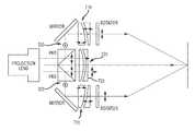
- FIG. 1A conventional implementation of polarization control at the projector is shown in FIG. 1 .
- nearly parallel raysemerge from the output of the lens 10 , appearing to originate from a pupil 12 inside of the lens 10 , and converge to form spots on a screen 14 .
- Ray bundles A, B, and C in FIG. 1are bundles forming spots at the bottom, center, and top of a screen 14 , respectively.
- the light 20 emerging from the projection lensis randomly polarized, depicted in FIG. 1 as both s- and p-polarized light (s-polarized light is conventionally represented as ‘o’; p-polarized light is represented with a double arrow-ended line).
- the light 20passes through a linear polarizer 22 , resulting in a single polarization state after the polarizer 22 .
- the orthogonal polarization stateis absorbed (or reflected), and the light flux after the polarizer 22 is typically less than half of the original flux, thus resulting in a dimmer final image.
- the polarization switch 30is synchronized with the image frame, and the polarization state 24 emerging from the polarization switch is alternated, producing images of alternately orthogonal polarization at the screen.
- Polarization-selective eyewearallows images of one polarization to pass to the left eye, and images of the orthogonal polarization to pass to the right eye. By presenting different images to each eye, 3D imagery can be synthesized.
- This conventional systemhas been used in theaters.
- the conventional systemrequires that greater than 50% of the light is absorbed by the polarizer, and the resulting image is greater than 50% dimmer than that of a typical 2D theater.
- the dimmer imagemay limit the size of theater used for 3D applications and/or may provide a less desirable viewing experience for the audience.
- an optical systemmay include a polarization conversion system.
- the polarization conversion systemmay include at least a polarization beam splitter (PBS) operable to receive randomly-polarized light bundles from a projector lens, and direct first light bundles having a first state of polarization (SOP) along a first light path, and direct second light bundles having a second SOP along a second light path, a polarization rotator located on the first light path, the polarization rotator being operable to translate the first SOP to the second SOP and a polarization switch operable to receive first and second light bundles from the first and second light paths respectively, and to selectively translate the polarization states of the first and second light bundles to one of a first output SOP and a second output SOP.
- PBSpolarization beam splitter
- the polarization switchmay include first and second polarization switch panels, the first polarization switch panel receiving light from the first light path, and the second polarization switch panel receiving light from the second light path.
- the polarization conversion systemmay also include at least one of the following: providing a curved surface on the fold mirror with optical power that compensates for the magnification difference; (2) adding a Fresnel or diffractive surface with optical power to the reflecting element to compensate for the magnification difference; (3) adding a refractive element (lens) between the reflecting element and polarization switch, or between the PBS and reflecting element; or (4) addition of a telephoto lens.
- optical systemshaving at least one polarization beam splitter (PBS).
- the PBSis operable to receive randomly-polarized light bundles from a projector lens.
- the PBSis further operable to direct light bundles having a state of polarization (SOP) along a light path and operable to direct other light bundles having a different SOP along different light paths.
- the light pathshave optical path lengths which may differ.
- Each light pathproduces an image having a distortion which may differ from the distortion of an image produced by a different light path.
- a compensation in a light pathis operable to convert a non-compensated distortion of an image into a compensated distortion that more closely matches the distortion of images in other light paths.
- a compensationmay remove distortion from a light path, and in some embodiments, a compensation may add distortion to a light path. In some embodiments, the non-compensated distortion and/or the compensated distortion in a light path may be equivalent to substantially no distortion.
- a compensationmay create a vertical tilt in a lens, a half-lens, or a lens pair in a light path.
- a compensationmay be achieved by adjusting a mounting location associated with the optical system, by a mechanical device such as a shim or a hinge, or by some other process or device.
- FIG. 1is a schematic diagram illustrating a polarization conversion system, in accordance with the present disclosure
- FIG. 2is a schematic diagram illustrating a polarization conversion system, in accordance with the present disclosure
- FIG. 3is a schematic diagram illustrating a polarization conversion system with no lens tilt, in accordance with the present disclosure
- FIG. 4Ais a diagram illustrating reflected light path distortion on-screen in a polarization conversion system with no lens tilt, in accordance with the present disclosure
- FIG. 4Bis a diagram illustrating transmitted light path distortion on-screen in a polarization conversion system with no lens tilt, in accordance with the present disclosure
- FIG. 5is a schematic diagram illustrating a polarization conversion system with lens tilt, in accordance with the present disclosure
- FIG. 6Ais a diagram illustrating reflected light path distortion on-screen in a polarization conversion system with lens tilt, in accordance with the present disclosure
- FIG. 6Bis a diagram illustrating transmitted light path distortion on-screen in a polarization conversion system with lens tilt, in accordance with the present disclosure
- FIG. 7is a schematic diagram illustrating a stacked polarization system with tilted lens pairs for distortion matching, in accordance with the present disclosure
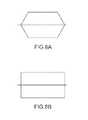
- FIG. 8Ais a diagram illustrating light path distortion on-screen in a stacked polarization system with no distortion matching, in accordance with the present disclosure.
- FIG. 8Bis a diagram illustrating light path distortion on-screen in a stacked polarization system with tilted lens pairs for distortion matching, in accordance with the present disclosure.
- an optical systemmay include a polarization conversion system.
- the polarization conversion systemmay include at least a polarization beam splitter (PBS) operable to receive randomly-polarized light bundles from a projector lens, and direct first light bundles having a first state of polarization (SOP) along a first light path, and direct second light bundles having a second SOP along a second light path, a polarization rotator located on the first light path, the polarization rotator being operable to translate the first SOP to the second SOP and a polarization switch operable to receive first and second light bundles from the first and second light paths respectively, and to selectively translate the polarization states of the first and second light bundles to one of a first output SOP and a second output SOP.
- PBSpolarization beam splitter
- the polarization switchmay include first and second polarization switch panels, the first polarization switch panel receiving light from the first light path, and the second polarization switch panel receiving light from the second light path.
- the polarization conversion systemmay also include at least one of the following: providing a curved surface on the fold mirror 116 with optical power that compensates for the magnification difference; (2) adding a Fresnel or diffractive surface with optical power to the reflecting element to compensate for the magnification difference; (3) adding a refractive element (lens) between the reflecting element and polarization switch, or between the PBS and reflecting element; or (4) addition of a telephoto lens.
- polarization conversion systemsthat receive light from a projector are described.
- the polarization conversion systemspresent a brighter screen image in cinematic applications utilizing polarized light for three-dimensional viewing.
- Polarization-preserving stereoscopic cinema systemshave been generally described in several patents and patent applications, for example U.S. Pat. No. 7,905,602 entitled “Polarization conversion system for stereoscopic projection” filed Sep. 28, 2007, U.S. Pat. No. 7,857,455 entitled “Combining P and S rays for bright stereoscopic projection” filed Oct. 18, 2006, U.S. Pat. No. 8,727,536 entitled “Polarization conversion system and method for projecting polarization encoded imagery” filed May 9, 2008, WO 2013/010167 entitled “Optical systems with compact back focal lengths” filed Jul. 16, 2012, and U.S. Pat. No. 8,220,934 entitled “Polarization conversion system for stereoscopic projection” filed Mar. 14, 2011, all of which are herein incorporated by reference in their entireties.
- Randomly polarized light from a projectoris split into orthogonal polarization states, re-directed and manipulated to produce matching polarization states, and overlaid on-screen for viewing.
- These systemsmay actively switch polarization states, for example with liquid-crystal switches or use passive components in dual projector configurations or one projector per eye which may provide greater image brightness.
- Three-dimensional (3D) imagerycan be synthesized using polarization control following the projector and polarization controlling eyewear (see, e.g., U.S. Pat. No. 4,792,850 to Lipton, which is herein incorporated by reference in its entirety).
- FIG. 1A conventional implementation of polarization control at the projector is shown in FIG. 1 .
- nearly parallel raysemerge from the output of the lens 10 , appearing to originate from a pupil 12 inside of the lens 10 , and converge to form spots on a screen 14 .
- Ray bundles A, B, and C in FIG. 1are bundles forming spots at the bottom, center, and top of a screen 14 , respectively.
- the light 20 emerging from the projection lensis randomly polarized, depicted in FIG. 1 as both s- and p-polarized light (s-polarized light is conventionally represented as ‘o’; p-polarized light is represented with a double arrow-ended line).
- the light 20passes through a linear polarizer 22 , resulting in a single polarization state after the polarizer 22 .
- the orthogonal polarization stateis absorbed (or reflected), and the light flux after the polarizer 22 is typically less than half of the original flux, thus resulting in a dimmer final image.
- the polarization switch 30is synchronized with the image frame, and the polarization state 24 emerging from the polarization switch is alternated, producing images of alternately orthogonal polarization at the screen.
- Polarization-selective eyewearallows images of one polarization to pass to the left eye, and images of the orthogonal polarization to pass to the right eye. By presenting different images to each eye, 3D imagery can be synthesized.
- This conventional systemhas been used in theaters.
- the conventional systemrequires that greater than 50% of the light is absorbed by the polarizer, and the resulting image is greater than 50% dimmer than that of a typical 2D theater.
- the dimmer imagemay limit the size of theater used for 3D applications and/or may provide a less desirable viewing experience for the audience.
- FIG. 2is a schematic diagram showing a polarization conversion system (PCS) 100 for cinematic projection.
- An embodiment of the polarization conversion system 100includes a polarizing beam splitter (PBS) 112 , a polarization rotator 114 , for example a half-wave plate, a reflecting element 116 , for example a fold mirror, and a polarization switch 120 , arranged as shown.
- the polarization conversion system 100may receive images from a conventional projector with a projection lens 122 .
- ray bundles A, B, and Cemerge randomly polarized from the lens 122 and are projected toward a screen 130 to form an image.
- a PBS 112is inserted in place of the polarizer 22 shown in FIG. 1 .
- the PBS 112transmits P-polarized light 124 , and reflects S-polarized light 126 .
- the P-polarized light 124passes through the polarization switch (bundles A, B, and C) and is rotated by the polarization switch in alternating frames, same as bundles A, B, and C in FIG. 1 .
- the S-polarized light 126 reflected by the PBS 112passes through a polarization rotator 114 (e.g., a half-wave plate, preferably achromatic in some embodiments) and is rotated to p-polarized light 128 .
- the new p-polarized light 128passes to a fold mirror 116 .
- the fold mirror 116reflects the new p-polarized light 128 and passes it to polarization switch 120 .
- the polarization switch 120acting on p-polarized ray bundles A′, B′, and C′, rotates the polarization of the ray bundles in alternating frames, in synchronization with the rotation of bundles A, B, and C.
- the position of bundles A′, B′, and C′ at the screenmay be adjusted (e.g., by adjusting the tilt of the fold mirror 116 ) to closely or exactly coincide with the positions of bundles A, B, and C at the screen. Since nearly all of the randomly polarized light 106 from the projection lens 122 is imaged at the screen 130 with a single polarization state, the resulting image of the system in FIG. 2 is approximately two times brighter than the image at the screen for the system in FIG. 1 .
- the PBS 112 in FIG. 2is depicted as a plate.
- the PBS platemay be constructed using a wire grid layer on glass (e.g., Proflux polarizer from Moxtek in Orem, Utah), polarization recycling film (e.g., Double Brightness Enhancing Film from 3M in St. Paul, Minn.), polarization recycling film on glass (for flatness), or a multi-dielectric layer on glass.
- the PBS 112 in FIG. 2could alternatively be implemented as a glass cube (with wire grid, polarization recycling film, or dielectric layers along the diagonal) to reduce astigmatism in the final image associated with light passing through a tilted plate.
- the tilted plate PBS 112 in FIG. 2may, in various embodiments, be implemented with spherical, aspherical, cylindrical or toroidal surfaces to reduce astigmatism in the final image at the screen 130 .
- De-centered spherical, aspherical, cylindrical or toroidal surfaces on the plate, and/or additional de-centered spherical, aspherical, cylindrical or toroidal elements in the optical path after the platecan be implemented to reduce astigmatism in the final image. See, e.g., “Simple method of correcting the aberrations of a beamsplitter in converging light,” V. Doherty and D. Shafer, Proc. SPIE, Vol. 0237, pp.
- a second flat platemay be inserted into the system after the tilted PBS plate 112 and its tilt adjusted to reduce or correct astigmatism in the final image.
- the polarization rotator 114 in FIG. 2may be an achromatic half-wave plate.
- the half-wave platemay be implemented with polymer films (e.g., Achromatic Retardation Plate from ColorLink, Inc., Boulder, Colo.), quartz plates, or a static liquid crystal device optionally patterned to account for geometric polarization alteration.
- the half-wave plate 114may be positioned as shown in FIG. 2 , or in other embodiments, it may be positioned between the fold mirror 116 and polarization switch 120 , intersecting ray bundles A′, B′, and C′.
- This implementationmay be desirable, as bundles A′, B′, and C′ reflect from the fold mirror 116 in s-polarization state and mirrors often have a higher reflection for s-polarized light.
- the half-wave plate 114should be located such that bundles A′ and C do not overlap at the plate.
- the polarization rotator 114is located in the second light path, it may alternatively be placed in the first light path instead, and the polarization conversion system will operate in a similar manner in accordance with the principles of the present disclosure.
- the fold mirror 116may be replaced with a PBS element (e.g., wire grid plate).
- a purer polarizationmay be maintained after the PBS element.
- Polarization switch 120may be a switch as taught by U.S. Pat. No. 4,792,850; a switch as taught by any of the switches of commonly-assigned U.S. Pat. No. 7,528,906 entitled “Achromatic Polarization Switches” filed Jun. 14, 2006; hereby incorporated by reference in its entirety, or any other polarization switch known in the art that selectively transforms an incoming state of polarization.
- the polarization switch 120can be split, for example, to increase yield of the device. If the polarization switch 120 is split, it is desirable that the two devices are located such that there is no overlap of bundles A′ and C in FIG. 2 .
- Splitting the polarization switch 120allows one portion to be relocated in the A′, B′, C′ optical path between the half-wave plate 114 and fold mirror 116 .
- Placing the polarization switch 120 heremay call for the fold mirror 116 to have better polarization preserving properties (e.g., a Silflex coating from Oerlikon in Golden, Colo.) as this may be the last element in the A′, B′, C′ optical path prior to the screen.
- the optical path of ray bundle A′is longer than that of ray bundle A (similarly B′-B and C′-C) resulting in a magnification difference between the images produced by A′, B′, C′ and A, B, C.
- This magnification differencemay be unacceptable to an audience, especially for wide angle and short-throw projection systems.
- Some techniques for correcting this magnification differencemay include (1) providing a curved surface on the fold mirror 116 with optical power that compensates for the magnification difference; this solution is achromatic, which is desirable; (2) adding a Fresnel or diffractive surface with optical power to the fold mirror 116 to compensate for the magnification difference (which may or may not be achromatic); (3) adding a refractive element (lens) between the fold mirror 116 and polarization switch 120 , or between the PBS 112 and fold mirror 116 ; a singlet lens is unlikely to be achromatic, but a doublet solution can be achromatic; (4) addition of a telephoto lens as illustrated in FIGS. 3 and 4 ; or (5) any combination of at least two of the above techniques.
- p-polarized lightis transmitted toward the polarization switch 120 , while s-polarized light is directed toward half-wave plate 114 , it should be apparent to a person of ordinary skill in the art that an alternative configuration may be employed in which s-polarized light is transmitted toward the polarization switch 120 , while p-polarized light is directed toward the half-wave plate 114 .
- FIG. 3depicts a polarization conversion system which may be used for creating stereoscopic imagery in digital cinema.
- the two optical paths(a reflected path 320 and a transmitted path 330 ) may have different optical path lengths. Without some form of compensation, the two images produced by the two optical paths may not overlay well on-screen.
- a lens pair 350may be included in the transmitted path 330 , for example, to change the magnification of the transmitted path image to better match the reflected path image.
- FIG. 4A and FIG. 4Bdepict the image distortions, magnified 100 ⁇ , in the two optical paths when the throw distance becomes very short.
- FIG. 4Ashows the trapezoidal distortion of the image in the reflected path 320
- FIG. 4Bshows the relatively undistorted nature of the image in the transmitted path 330 .
- the reflected path imageagain can be excessively trapezoidal resulting in overlay difficulties.
- the mismatch in distortion of the two optical pathscan be overcome in short throw and low throw ratio situations by introducing a matching trapezoidal distortion in the transmitted optical path 330 that substantially matches the distortion in the reflected optical path 320 .
- trapezoidal distortionmay be removed from the reflected optical path 320 to better match the transmitted path 330 .
- a compensationmay be included in one or both of the light paths to convert the native (non-compensated) distortion into compensated distortions that more closely match.
- FIG. 5is similar to FIG. 3 , except that in FIG. 5 a single lens 520 in the lens pair 350 is tilted by approximately 1.5 degrees in the transmitted path 330 .
- the lensmay be tilted by a mechanical shim, by a hinge, by an adjustment of mechanical mounting locations, or by any number of mechanical means. For example, a 2.9 millimeter shim may be placed at location 510 to achieve the tilt.
- FIG. 6A and FIG. 6Bdepict the image distortions, magnified 100 ⁇ , in the two optical paths when the throw distance becomes very short and a single lens 520 in a lens pair 350 is tilted by approximately 1.5 degrees.
- FIG. 6Ais similar to FIG. 4A and shows the trapezoidal distortion of the image in the reflected path 320
- FIG. 6Bshows the compensated distortion of the image in the transmitted path 330 .
- the images in the reflected path 320 and the transmitted path 330are now better overlaid because compensating trapezoidal distortion has been introduced in the transmitted path 330 that is similar to the distortion in the reflected path 320 , resulting in significant image overlay improvement in the corners in a short throw environment.
- This type of distortion matchingcan be used with single or multiple projector systems to improve image overlay at the screen.
- FIG. 7depicts such a system where two lens pairs 710 are included, one for each reflected path 320 , to reduce the trapezoidal distortion in each of the reflected paths 320 . Additionally depicted is an optional lens pair 720 in the transmitted path 330 for further magnification matching. Note that the lens pairs 710 in the reflected paths 320 may be lens halves, as depicted in FIG. 7 , or the lens pairs 710 may be full lenses. FIG.
- FIG. 8Aillustrates light path distortion on-screen in a stacked polarization system with no distortion matching
- FIG. 8Billustrates light path distortion on-screen in a stacked polarization system with tilted lens pairs for distortion matching, as depicted in FIG. 7 .
- the terms “substantially” and “approximately”provide an industry-accepted tolerance for its corresponding term and/or relativity between items. Such an industry-accepted tolerance ranges from zero to ten percent and corresponds to, but is not limited to, component values, angles, et cetera. Such relativity between items ranges between approximately zero percent to ten percent.
Landscapes
- Physics & Mathematics (AREA)
- General Physics & Mathematics (AREA)
- Optics & Photonics (AREA)
- Nonlinear Science (AREA)
Abstract
Description
Claims (12)
Priority Applications (1)
| Application Number | Priority Date | Filing Date | Title |
|---|---|---|---|
| US15/348,186US10459321B2 (en) | 2015-11-10 | 2016-11-10 | Distortion matching polarization conversion systems and methods thereof |
Applications Claiming Priority (2)
| Application Number | Priority Date | Filing Date | Title |
|---|---|---|---|
| US201562253274P | 2015-11-10 | 2015-11-10 | |
| US15/348,186US10459321B2 (en) | 2015-11-10 | 2016-11-10 | Distortion matching polarization conversion systems and methods thereof |
Publications (2)
| Publication Number | Publication Date |
|---|---|
| US20170131624A1 US20170131624A1 (en) | 2017-05-11 |
| US10459321B2true US10459321B2 (en) | 2019-10-29 |
Family
ID=58663961
Family Applications (1)
| Application Number | Title | Priority Date | Filing Date |
|---|---|---|---|
| US15/348,186Active2037-06-30US10459321B2 (en) | 2015-11-10 | 2016-11-10 | Distortion matching polarization conversion systems and methods thereof |
Country Status (2)
| Country | Link |
|---|---|
| US (1) | US10459321B2 (en) |
| WO (1) | WO2017083526A1 (en) |
Citations (351)
| Publication number | Priority date | Publication date | Assignee | Title |
|---|---|---|---|---|
| US1128979A (en) | 1912-06-01 | 1915-02-16 | Walter Hess | Stereoscopic picture. |
| US1970311A (en) | 1931-02-14 | 1934-08-14 | Bell Telephone Labor Inc | Projection of images for viewing in stereoscopic relief |
| US2133121A (en) | 1936-04-02 | 1938-10-11 | Richard I Stearns | Stereoscopic screen and method stereoscopic vision |
| US2247969A (en) | 1937-12-31 | 1941-07-01 | Adlake Co | Edge glow lighting system |
| US2480178A (en) | 1946-05-08 | 1949-08-30 | Ivan H Zinberg | Light conductor |
| US2810905A (en) | 1949-08-23 | 1957-10-22 | Sperry Rand Corp | High frequency directive beam apparatus |
| US3409351A (en) | 1966-02-07 | 1968-11-05 | Douglas F. Winnek | Composite stereography |
| US3715154A (en) | 1970-03-11 | 1973-02-06 | Agfa Gevaert Ag | Three-dimensional picture projection |
| US4057323A (en) | 1974-08-30 | 1977-11-08 | Ward Jr Robertson | Projection screen |
| US4528617A (en) | 1982-02-08 | 1985-07-09 | Sheltered Workshop For The Disabled, Inc. | Light distribution apparatus |
| US4542958A (en) | 1983-01-13 | 1985-09-24 | Vasco, Ltd. | Variable aspect display |
| US4804253A (en) | 1986-05-15 | 1989-02-14 | General Electric Company | Lenticular filter for display devices |
| US4807978A (en) | 1987-09-10 | 1989-02-28 | Hughes Aircraft Company | Color display device and method using holographic lenses |
| US4829365A (en) | 1986-03-07 | 1989-05-09 | Dimension Technologies, Inc. | Autostereoscopic display with illuminating lines, light valve and mask |
| US4914553A (en) | 1984-07-26 | 1990-04-03 | Sharp Kabushiki Kaisha | Lighting device |
| US5278608A (en) | 1992-05-19 | 1994-01-11 | Eastman Kodak Company | Electronically printed depth photography system with improved viewing range |
| WO1994006249A1 (en) | 1992-09-09 | 1994-03-17 | Eichenlaub Jesse B | Stroboscopic illumination system for video displays |
| WO1994006249B1 (en) | 1993-09-07 | 1994-04-14 | Stroboscopic illumination system for video displays | |
| US5347644A (en) | 1992-06-11 | 1994-09-13 | Sedlmayr Steven R | Three-dimensional image display device and systems and methods for implementation thereof |
| US5349419A (en) | 1992-04-15 | 1994-09-20 | Fuji Photo Film Co., Ltd. | Method and apparatus for recording stereoscopic images |
| US5355188A (en)* | 1993-09-09 | 1994-10-11 | In Focus Systems, Inc. | Method and apparatus for distortion correction in optical projectors |
| EP0653891A1 (en) | 1993-11-12 | 1995-05-17 | Sharp Kabushiki Kaisha | Three-dimensional projection display apparatus |
| EP0656555A1 (en) | 1993-12-01 | 1995-06-07 | SHARP Corporation | Display for 3D images |
| WO1995020811A1 (en) | 1994-01-31 | 1995-08-03 | Sdl, Inc. | Laser illuminated display system |
| US5459592A (en) | 1992-04-24 | 1995-10-17 | Sharp Kabushiki Kaisha | Projection display system including a collimating tapered waveguide or lens with the normal to optical axis angle increasing toward the lens center |
| WO1995027915A1 (en) | 1994-04-11 | 1995-10-19 | Minnesota, Mining And Manufacture Company | Tapered multilayer luminaire device |
| US5466926A (en) | 1992-01-27 | 1995-11-14 | Kabushiki Kaisha Toshiba | Colored microlens array and method of manufacturing same |
| JPH0870475A (en) | 1994-06-23 | 1996-03-12 | Sanyo Electric Co Ltd | Method and device for encoding and decoding stereoscopic animation |
| US5510831A (en) | 1994-02-10 | 1996-04-23 | Vision Iii Imaging, Inc. | Autostereoscopic imaging apparatus and method using suit scanning of parallax images |
| US5528720A (en) | 1992-03-23 | 1996-06-18 | Minnesota Mining And Manufacturing Co. | Tapered multilayer luminaire devices |
| EP0721131A2 (en) | 1994-12-29 | 1996-07-10 | Sharp Kabushiki Kaisha | Observer tracking autostereoscopic display and method of tracking an observer |
| JPH08211334A (en) | 1994-10-21 | 1996-08-20 | Sharp Corp | Light sources, 3D displays and directional displays |
| JPH08254617A (en) | 1995-01-30 | 1996-10-01 | Hoshi Seisakusho:Kk | Surface light emitting device |
| US5581402A (en) | 1993-11-22 | 1996-12-03 | Eastman Kodak Company | Method for producing an improved stereoscopic picture and stereoscopic picture obtained according to this method |
| JPH08340556A (en) | 1995-06-14 | 1996-12-24 | Mitsubishi Electric Corp | 3D image display device |
| US5588526A (en) | 1994-04-01 | 1996-12-31 | Insight, Inc. | Flat box system with multiple view optics |
| CN1142869A (en) | 1993-12-21 | 1997-02-12 | 美国3M公司 | Reflective polarizer with brightness enhancement |
| US5697006A (en) | 1992-02-06 | 1997-12-09 | Fuji Photo Film Co., Ltd. | Method and apparatus for recording stereoscopic images and lenticular recording material used therefor |
| US5703667A (en) | 1996-05-31 | 1997-12-30 | Shimada Precision, Co., Ltd. | Light guide plates and light guide plate assembly utilizing diffraction grating |
| US5727107A (en) | 1995-08-03 | 1998-03-10 | Nitto Denko Corporation | Light guide plate, surface light source device, polarized light source device and liquid crystal display |
| EP0830984A2 (en) | 1996-09-19 | 1998-03-25 | Hella KG Hueck & Co. | Vehicle light |
| EP0833183A1 (en) | 1996-09-27 | 1998-04-01 | Sharp Kabushiki Kaisha | LCD spatial light modulator as electronic parallax barrier |
| WO1998021620A1 (en) | 1996-11-14 | 1998-05-22 | Philips Electronics N.V. | Autostereoscopic display apparatus |
| US5771066A (en) | 1997-01-03 | 1998-06-23 | Barnea; Daniel I. | Three dimensional display device |
| US5796451A (en) | 1993-10-23 | 1998-08-18 | Samsung Display Devices Co., Ltd. | Liquid crystal cell with an external color filter |
| EP0860729A2 (en) | 1997-02-20 | 1998-08-26 | Canon Kabushiki Kaisha | Image display system, information processing apparatus, and method of controlling the same |
| US5808792A (en) | 1995-02-09 | 1998-09-15 | Sharp Kabushiki Kaisha | Autostereoscopic display and method of controlling an autostereoscopic display |
| US5875055A (en) | 1995-06-29 | 1999-02-23 | Canon Kabushiki Kaisha | Stereoscopic image display method and stereoscopic image display apparatus using the same |
| WO1999011074A1 (en) | 1997-08-22 | 1999-03-04 | HEINRICH-HERTZ-INSTITUT FüR NACHRICHTENTECHNIK BERLIN GMBH | Device for automatically adjusting an autostereoscopic flat screen |
| US5896225A (en) | 1993-05-24 | 1999-04-20 | Deutsche Thomson Brandt Gmbh | Device for stereoscopic image observation within an increased observation area |
| US5903388A (en) | 1992-06-11 | 1999-05-11 | Sedlmayr Steven R | High efficiency electromagnetic beam projector and systems and method for implementation thereof |
| US5933276A (en) | 1994-04-13 | 1999-08-03 | Board Of Trustees, University Of Arkansas, N.A. | Aberration-free directional image window sheet |
| EP0939273A1 (en) | 1998-02-26 | 1999-09-01 | Nitto Denko Corporation | Light guide plate, planar light source unit and reflection-type liquid-crystal display device |
| US5956001A (en) | 1996-03-15 | 1999-09-21 | Sharp Kabushiki Kaisha | Image display device |
| US5959702A (en) | 1996-10-04 | 1999-09-28 | Goodman; John Mott | Lensless video projector |
| US5971559A (en) | 1994-08-12 | 1999-10-26 | Enplas Corporation | Surface light source device |
| US6008484A (en) | 1996-09-27 | 1999-12-28 | Sharp Kabushiki Kaisha | Observer tracking directional display and observer tracking illumination system |
| US6023315A (en) | 1995-07-04 | 2000-02-08 | Sharp Kabushiki Kaisha | Spatial light modulator and directional display |
| JP2000048618A (en) | 1998-07-29 | 2000-02-18 | Casio Comput Co Ltd | Lighting panel and display device using the same |
| US6044196A (en) | 1992-03-23 | 2000-03-28 | Minnesota Mining & Manufacturing, Co. | Luminaire device |
| US6055013A (en) | 1997-02-04 | 2000-04-25 | Sharp Kabushiki Kaisha | Autostereoscopic display |
| US6061179A (en) | 1996-01-23 | 2000-05-09 | Canon Kabushiki Kaisha | Stereoscopic image display apparatus with two-/three-dimensional image display switching function |
| US6064424A (en) | 1996-02-23 | 2000-05-16 | U.S. Philips Corporation | Autostereoscopic display apparatus |
| US6075557A (en) | 1997-04-17 | 2000-06-13 | Sharp Kabushiki Kaisha | Image tracking system and method and observer tracking autostereoscopic display |
| JP2000200049A (en) | 1998-11-02 | 2000-07-18 | Sony Corp | Reflection type display device |
| US6094216A (en) | 1995-05-22 | 2000-07-25 | Canon Kabushiki Kaisha | Stereoscopic image display method, and stereoscopic image display apparatus using the method |
| US6108059A (en) | 1998-03-10 | 2000-08-22 | Sony Corporation | Reflective display having a laminated structure of a polarizer and quarter wave plate being attached to a light guide plate |
| US6118584A (en) | 1995-07-05 | 2000-09-12 | U.S. Philips Corporation | Autostereoscopic display apparatus |
| US6128054A (en) | 1996-09-06 | 2000-10-03 | Central Research Laboratories Limited | Apparatus for displaying an image |
| US6144118A (en) | 1998-09-18 | 2000-11-07 | General Scanning, Inc. | High-speed precision positioning apparatus |
| US6169853B1 (en)* | 1998-01-05 | 2001-01-02 | Asahi Kogaku Kogyo Kabushiki Kaisha | Zooming optical system |
| US6172723B1 (en) | 1997-11-10 | 2001-01-09 | Canon Kabushiki Kaisha | Reflection type LCD pixel having outer low reflectivity region surrounding high reflectivity region upon which microlens light is focussed |
| JP2001093321A (en) | 1999-09-22 | 2001-04-06 | Hitachi Ltd | Illumination device and display device using the same |
| US6219113B1 (en) | 1996-12-17 | 2001-04-17 | Matsushita Electric Industrial Co., Ltd. | Method and apparatus for driving an active matrix display panel |
| WO2001027528A1 (en) | 1999-10-08 | 2001-04-19 | 3M Innovative Properties Company | Display illumination device and method of enhancing brightness in a display illumination device |
| US6224214B1 (en) | 1997-03-27 | 2001-05-01 | Litton Systems, Inc. | Autostereo projection system |
| US6232592B1 (en) | 1998-07-10 | 2001-05-15 | Canon Kabushiki Kaisha | Light guide member, illumination device, and image reading apparatus using them |
| US20010001566A1 (en) | 1996-07-12 | 2001-05-24 | Richard Robert Moseley | Directional display for a directional display having an angular intensity profile compensator |
| US6256447B1 (en) | 1998-12-31 | 2001-07-03 | Physical Optics Corporation | Backlight for correcting diagonal line distortion |
| US6262786B1 (en) | 1996-05-27 | 2001-07-17 | C.R.F. Societa Consortile Per Azioni | Devices with micro-filters and micro-choppers for dynamic selection of colours and images |
| CN1307481A (en) | 1998-04-27 | 2001-08-08 | 普雷西斯药品公司 | Methods for treating hot flashes and gynaecomastia |
| WO2001061241A1 (en) | 2000-02-16 | 2001-08-23 | 3M Innovative Properties Company | Wedge light extractor with risers |
| US6295109B1 (en) | 1997-12-26 | 2001-09-25 | Sharp Kabushiki Kaisha | LCD with plurality of pixels having reflective and transmissive regions |
| JP2001281456A (en) | 2000-03-30 | 2001-10-10 | Enplas Corp | Light transmission plate, surface light source device and display device |
| US6302541B1 (en) | 1998-06-20 | 2001-10-16 | Christoph Grossmann | Method and device for autostereoscopy |
| US6305813B1 (en) | 1999-08-11 | 2001-10-23 | North American Lighting, Inc. | Display device using a light guide for exterior automotive lighting |
| WO2001079923A1 (en) | 2000-04-18 | 2001-10-25 | 3M Innovative Properties Company | Transflective display with non-inverting image |
| US20010050686A1 (en) | 2000-02-15 | 2001-12-13 | U.S. Philips Corporation | Autostereoscopic display driver |
| US20020018299A1 (en) | 2000-03-17 | 2002-02-14 | Stephen Daniell | Optical reproduction system |
| JP2002049004A (en) | 2000-07-31 | 2002-02-15 | Mixed Reality Systems Laboratory Inc | Display controller and method |
| US6373637B1 (en) | 2000-09-13 | 2002-04-16 | Eastman Kodak Company | Diagonal lenticular image system |
| US6377295B1 (en) | 1996-09-12 | 2002-04-23 | Sharp Kabushiki Kaisha | Observer tracking directional display |
| US6422713B1 (en) | 2000-10-17 | 2002-07-23 | Ford Global Technologies, Inc. | Thin-sheet collimation optics for diode laser illumination systems for use in night vision and exterior lighting applications |
| US20020113866A1 (en) | 1996-01-31 | 2002-08-22 | Naosato Taniguchi | Stereoscopic image display apparatus whose observation area is widened |
| US20020113246A1 (en) | 2001-01-25 | 2002-08-22 | Hideo Nagai | Light-emitting unit, light-emitting unit assembly, and lighting apparatus produced using a plurality of light-emitting units |
| US6456340B1 (en) | 1998-08-12 | 2002-09-24 | Pixonics, Llc | Apparatus and method for performing image transforms in a digital display system |
| US6464365B1 (en) | 1999-07-23 | 2002-10-15 | Bae Systems Information And Electronic Systems Integration Inc. | Light collimator for liquid crystal displays |
| US6476850B1 (en) | 1998-10-09 | 2002-11-05 | Kenneth Erbey | Apparatus for the generation of a stereoscopic display |
| US20030046839A1 (en) | 1999-02-10 | 2003-03-13 | Dai Nippon Printing Co., Ltd. | Display apparatus |
| US20030117790A1 (en) | 2001-12-21 | 2003-06-26 | Au Optronics Corp. | Backlight unit of liquid crystal display |
| US20030133191A1 (en) | 2002-01-16 | 2003-07-17 | Kazuo Morita | Three-dimensional observation apparatus |
| US20030137821A1 (en) | 2002-01-23 | 2003-07-24 | Fujitsu Display Technologies Corp. | Light guide plate, light source device equipped therewith and display device |
| US20030137738A1 (en) | 2002-01-18 | 2003-07-24 | Fuji Photo Optical Co., Ltd. | Optical device with barrier layer, optical system, and projector apparatus |
| JP2003215705A (en) | 2001-11-06 | 2003-07-30 | Samsung Electronics Co Ltd | Illumination system and projection system adopting the same |
| US6654156B1 (en) | 1998-12-23 | 2003-11-25 | Holographic Imaging Llc | Image display system |
| CN1466005A (en) | 2002-06-20 | 2004-01-07 | 三星电子株式会社 | Lighting device for flat panel display |
| US20040008877A1 (en) | 2002-02-15 | 2004-01-15 | Ocular Sciences, Inc. | Systems and methods for inspection of ophthalmic lenses |
| US20040021809A1 (en) | 2000-07-11 | 2004-02-05 | Ken Sumiyoshi | Liquid crystal display device |
| EP1394593A1 (en) | 2002-08-27 | 2004-03-03 | Nec Corporation | 3D image / 2D image switching display apparatus and portable terminal device |
| US20040042233A1 (en) | 2002-08-30 | 2004-03-04 | Fujitsu Display Technologies Corporation | Lighting unit and display device |
| US20040046709A1 (en) | 2002-09-05 | 2004-03-11 | Kazutora Yoshino | 3 Dimensional image projector and holodeck |
| CN1487332A (en) | 2002-09-17 | 2004-04-07 | ������������ʽ���� | autostereoscopic display |
| US6724452B1 (en) | 1997-06-12 | 2004-04-20 | Fujitsu Display Technologies Corporation | Vertically aligned (VA) liquid crystal display device |
| US6731355B2 (en) | 2002-03-08 | 2004-05-04 | Citizen Electronics Co., Ltd. | Lighting panel for a display |
| US6736512B2 (en) | 2000-02-21 | 2004-05-18 | Sony International (Europe) Gmbh | Pixel element for a three-dimensional screen |
| US20040105264A1 (en) | 2002-07-12 | 2004-06-03 | Yechezkal Spero | Multiple Light-Source Illuminating System |
| US20040108971A1 (en) | 1998-04-09 | 2004-06-10 | Digilens, Inc. | Method of and apparatus for viewing an image |
| US20040109303A1 (en) | 2002-12-04 | 2004-06-10 | Eugene Olczak | Polarization sensitive optical substrate |
| US20040135741A1 (en) | 2002-10-31 | 2004-07-15 | Pioneer Corporation | Apparatus and method for displaying three-dimensional image |
| US20040170011A1 (en) | 2002-11-04 | 2004-09-02 | Samsung Electronics Co., Ltd. | Backlight unit |
| US6801243B1 (en) | 1997-07-23 | 2004-10-05 | Koninklijke Philips Electronics N.V. | Lenticular screen adaptor |
| US6816158B1 (en) | 1998-10-30 | 2004-11-09 | Lemelson Jerome H | Three-dimensional display system |
| JP2004319364A (en) | 2003-04-18 | 2004-11-11 | Alps Electric Co Ltd | Lighting system and liquid crystal display device |
| US6825985B2 (en) | 2001-07-13 | 2004-11-30 | Mems Optical, Inc. | Autostereoscopic display with rotated microlens and method of displaying multidimensional images, especially color images |
| US20040263969A1 (en) | 2002-11-25 | 2004-12-30 | Lenny Lipton | Lenticular antireflection display |
| US20040263968A1 (en) | 2003-04-21 | 2004-12-30 | Masanori Kobayashi | Method and apparatus for displaying three-dimensional stereo image using light deflector |
| US20050007753A1 (en) | 2001-06-01 | 2005-01-13 | Van Hees Antonius Johannes Maria | Compact illumination system and display device |
| US6847488B2 (en) | 2001-04-07 | 2005-01-25 | Cambridge Flat Projection Displays Limited | Far-field display |
| US6847354B2 (en) | 2000-03-23 | 2005-01-25 | The United States Of America As Represented By The Administrator Of The National Aeronautics And Space Administration | Three dimensional interactive display |
| US6859240B1 (en) | 2000-01-27 | 2005-02-22 | Mems Optical Inc. | Autostereoscopic display |
| GB2405542A (en) | 2003-08-30 | 2005-03-02 | Sharp Kk | Multiple view directional display having display layer and parallax optic sandwiched between substrates. |
| US6867828B2 (en) | 1999-10-08 | 2005-03-15 | International Business Machines Corporation | Light guide apparatus, a backlight apparatus and a liquid crystal display apparatus |
| US6870671B2 (en) | 2000-10-03 | 2005-03-22 | Cambridge 3D Display Limited | Flat-panel display |
| US6883919B2 (en) | 2000-11-25 | 2005-04-26 | Cambridge Flat Projection Displays Limited | Achromatic flat-panel display |
| JP2005116266A (en) | 2003-10-06 | 2005-04-28 | Seiko Epson Corp | Lighting device, display device, and projector |
| US20050094295A1 (en) | 2002-01-31 | 2005-05-05 | Tomoyoshi Yamashita | Light deflection element and light source apparatus using the same |
| US20050110980A1 (en) | 2003-03-14 | 2005-05-26 | Fujitsu Limited | Measurement method by OTDR and terminal station apparatus |
| JP2005135844A (en) | 2003-10-31 | 2005-05-26 | Sony Corp | Optical element and backlight device |
| US20050135116A1 (en) | 2003-12-17 | 2005-06-23 | 3M Innovative Properties Company | Illumination device |
| JP2005183030A (en) | 2003-12-16 | 2005-07-07 | Seiko Epson Corp | Light guide plate and lighting device |
| US20050174768A1 (en) | 2004-02-11 | 2005-08-11 | 3M Innovative Properties Company | Illumination system |
| US20050180167A1 (en) | 2002-03-28 | 2005-08-18 | Hoelen Christoph G.A. | Compact lighting system and display device |
| US20050190345A1 (en) | 2004-02-27 | 2005-09-01 | Dubin Matthew B. | Electro-optical dimming system |
| JP2005259361A (en) | 2004-03-09 | 2005-09-22 | Goyo Paper Working Co Ltd | Surface light source device |
| US20050237488A1 (en) | 2004-04-22 | 2005-10-27 | Futoshi Yamasaki | Image display apparatus |
| CN1696788A (en) | 2004-05-11 | 2005-11-16 | 株式会社日立显示器 | LCD Monitor |
| US20050254127A1 (en) | 2004-05-12 | 2005-11-17 | Allan Evans | Time-sequential colour projection |
| US20050264717A1 (en) | 2004-05-25 | 2005-12-01 | Ko-Wei Chien | Three-dimensional display system and method thereof |
| US20050276071A1 (en) | 2002-09-19 | 2005-12-15 | Mitsubishi Denki Kabushiki Kaisha | Display unit and electronic apparatus with display unit |
| US20050274956A1 (en) | 2004-05-26 | 2005-12-15 | Bhat Jerome C | LED chip with integrated fast switching diode for ESD protection |
| US20050280637A1 (en) | 2004-06-18 | 2005-12-22 | Nec Corporation | Input and output device and terminal device |
| JP2006004877A (en) | 2004-06-21 | 2006-01-05 | Nippon Leiz Co Ltd | Light guide plate, and flat illumination device |
| US20060012845A1 (en) | 2004-07-13 | 2006-01-19 | Imation Corp. | Spatial light modulator device with diffusive element |
| JP2006031941A (en) | 2004-07-12 | 2006-02-02 | Sharp Corp | Planar light source unit |
| EP1634119A1 (en) | 2003-06-06 | 2006-03-15 | Cambridge Flat Projection Displays Limited | Scanning backlight for flat-panel display |
| US20060056166A1 (en) | 2004-09-09 | 2006-03-16 | Yeo Terence E | Enhanced LCD backlight |
| US20060114664A1 (en) | 2004-12-01 | 2006-06-01 | Seiko Epson Corporation | Light source device and image display device |
| US7058252B2 (en) | 2001-08-06 | 2006-06-06 | Ocuity Limited | Optical switching apparatus |
| US20060139447A1 (en) | 2004-12-23 | 2006-06-29 | Unkrich Mark A | Eye detection system and method for control of a three-dimensional display |
| US20060158729A1 (en) | 2003-02-21 | 2006-07-20 | Koninklijke Philips Electronics N.V. | Autostereoscopic display |
| US20060176912A1 (en) | 2005-02-07 | 2006-08-10 | Anikitchev Serguei G | Apparatus for projecting a line of light from a diode-laser array |
| US7091931B2 (en) | 2001-08-17 | 2006-08-15 | Geo-Rae Co., Ltd. | Method and system of stereoscopic image display for guiding a viewer's eye motion using a three-dimensional mouse |
| CN1823292A (en) | 2003-07-10 | 2006-08-23 | 奥库提有限公司 | directional display device |
| CN1826553A (en) | 2003-07-23 | 2006-08-30 | 夏普株式会社 | Liquid crystal display device |
| US7101048B2 (en) | 2001-09-25 | 2006-09-05 | Cambridge Flat Protection Displays Limited | Flat-panel projection display |
| US20060203200A1 (en) | 2003-03-07 | 2006-09-14 | Jun Koide | Illumination optical system and projection display optical system |
| US20060215129A1 (en) | 2003-04-16 | 2006-09-28 | Upstream Engineering Oy | 2D/3D data projector |
| US20060221642A1 (en) | 2005-03-31 | 2006-10-05 | Casio Computer Co., Ltd. | Illuminator for emitting at least two lights having directivity and display apparatus using same |
| US20060227427A1 (en) | 2003-09-22 | 2006-10-12 | Gene Dolgoff | Omnidirectional lenticular and barrier-grid image displays and methods for making them |
| US20060244918A1 (en) | 2005-04-27 | 2006-11-02 | Actuality Systems, Inc. | Minimized-thickness angular scanner of electromagnetic radiation |
| US20060250580A1 (en) | 2005-05-03 | 2006-11-09 | Eastman Kodak Company | Display apparatus using LCD panel |
| US7136031B2 (en) | 2000-12-18 | 2006-11-14 | Byoungho Lee | Reflecting three-dimensional display system |
| US20060262376A1 (en) | 2005-05-19 | 2006-11-23 | Jonathan Mather | Display |
| US20060269213A1 (en) | 2005-05-31 | 2006-11-30 | Bright View Electronics Co., Ltd. | Illumination apparatus providing longitudinal illumination |
| US20060284974A1 (en) | 2005-04-08 | 2006-12-21 | Lenny Lipton | Autostereoscopic display with planar pass-through |
| US20060291053A1 (en) | 2006-01-23 | 2006-12-28 | Colorlink, Inc. | Achromatic Polarization Switches |
| US20060291243A1 (en) | 2005-06-24 | 2006-12-28 | Nec Corporation | Optical member, light source apparatus, display apparatus, and terminal apparatus |
| US20070008406A1 (en) | 2005-07-08 | 2007-01-11 | Samsung Electronics Co., Ltd. | High resolution 2D-3D switchable autostereoscopic display apparatus |
| US20070013624A1 (en) | 2005-07-13 | 2007-01-18 | Grant Bourhill | Display |
| US20070035706A1 (en) | 2005-06-20 | 2007-02-15 | Digital Display Innovations, Llc | Image and light source modulation for a digital display system |
| US20070035829A1 (en) | 2003-09-30 | 2007-02-15 | Ocuity Limited | Directional display apparatus |
| US20070035964A1 (en) | 2002-12-06 | 2007-02-15 | General Electric Company | Brightness enhancement film with improved view angle |
| CN2872404Y (en) | 2006-03-06 | 2007-02-21 | 胡国辉 | High-brightness light-conductive board |
| US20070081110A1 (en) | 2005-10-10 | 2007-04-12 | Eastman Kodak Company | Backlight unit with linearly reduced divergence |
| US20070085105A1 (en) | 2005-10-18 | 2007-04-19 | Goldeneye, Inc. | Light emitting diode and side emitting lens |
| US7215475B2 (en) | 2003-07-10 | 2007-05-08 | Ocuity Limited | Lens array structure |
| US7215391B2 (en) | 2004-07-16 | 2007-05-08 | United Microelectronics Corp. | Liquid crystal on silicon display with micro color filters positioned on the top surface of the transparent substrate |
| US20070109401A1 (en) | 2005-11-14 | 2007-05-17 | Real D | Monitor with integral interdigitation |
| US20070115552A1 (en) | 2005-09-02 | 2007-05-24 | Colorlink, Inc. | Polarization beam splitter and combiner |
| US20070115551A1 (en) | 2005-04-01 | 2007-05-24 | Alexis Spilman | Space-variant waveplate for polarization conversion, methods and applications |
| US7239293B2 (en) | 1998-01-21 | 2007-07-03 | New York University | Autostereoscopic display |
| US20070153160A1 (en) | 2005-12-29 | 2007-07-05 | Hye-Sun Lee | Liquid crystal display device and method of fabricating the same |
| US20070183466A1 (en) | 2006-02-09 | 2007-08-09 | Samsung Electronics Co., Ltd. | Laser display device |
| US20070183018A1 (en) | 2003-02-27 | 2007-08-09 | Arkady Khachaturove | System for recovering input polarization state of optical beam at proportional intensity |
| US20070188667A1 (en) | 2003-12-18 | 2007-08-16 | Seereal Technologies Gmbh | Multi-user autostereoscopic display with position tracking |
| US20070189701A1 (en) | 2006-02-10 | 2007-08-16 | Chakmakjian Stephen H | Optical devices for guiding illumination |
| CN101029975A (en) | 2006-02-27 | 2007-09-05 | 三星电子株式会社 | High resolution 2d-3d switchable autostereoscopic display apparatus |
| US20070223252A1 (en) | 2006-03-24 | 2007-09-27 | Junwon Lee | Illumination apparatus and film |
| CN101049028A (en) | 2004-09-21 | 2007-10-03 | 夏普株式会社 | multi-view display |
| JP2007273288A (en) | 2006-03-31 | 2007-10-18 | Nippon Leiz Co Ltd | Light guide plate and flat lighting system |
| JP2007286652A (en) | 2003-07-23 | 2007-11-01 | Sharp Corp | Liquid crystal display |
| CN200983052Y (en) | 2006-11-27 | 2007-11-28 | 比亚迪股份有限公司 | A backlight module for 3D LCD |
| CN101114080A (en) | 2006-07-26 | 2008-01-30 | 三星电子株式会社 | Light-emitting device and display device using the light-emitting device |
| CN101142823A (en) | 2005-03-17 | 2008-03-12 | 皇家飞利浦电子股份有限公司 | Autostereoscopic display device and its color filter |
| US20080079662A1 (en) | 2006-10-03 | 2008-04-03 | Kabushiki Kaisha Toshiba. | Stereoscopic display apparatus |
| US20080084519A1 (en) | 2006-10-06 | 2008-04-10 | 3M Innovative Properties Company | Stereoscopic 3d liquid crystal display apparatus with scanning backlight |
| US7365908B2 (en) | 2001-11-08 | 2008-04-29 | Eugene Dolgoff | Tiling of panels for multiple-image displays |
| US7375886B2 (en) | 2004-04-19 | 2008-05-20 | Stereographics Corporation | Method and apparatus for optimizing the viewing distance of a lenticular stereogram |
| US20080128728A1 (en) | 2004-09-10 | 2008-06-05 | Luminus Devices, Inc. | Polarized light-emitting devices and methods |
| US7410286B2 (en) | 2001-08-02 | 2008-08-12 | Microsoft Corporation | Flat-panel display using tapered waveguide |
| JP2008204874A (en) | 2007-02-21 | 2008-09-04 | Fujifilm Corp | Surface lighting device |
| US20080225236A1 (en)* | 2006-09-29 | 2008-09-18 | Colorlink, Inc. | Polarization conversion systems for stereoscopic projection |
| US20080225205A1 (en) | 2007-03-13 | 2008-09-18 | Microsoft Corporation | Display With Focussed Illumination |
| US7430358B2 (en) | 2005-04-20 | 2008-09-30 | Wavefront Technology, Inc. | Elliptical diffusers used in displays |
| US20080259012A1 (en) | 1994-10-25 | 2008-10-23 | Fergason James L | Optical display system and method, active and passive dithering using birefringence, color image superpositioning and display enhancement with phase coordinated polarization switching |
| US20080291359A1 (en) | 2007-05-08 | 2008-11-27 | Junji Miyashita | Optical member, backlight unit and display apparatus |
| US20080297459A1 (en) | 2004-01-15 | 2008-12-04 | Hitachi Chemical Co., Ltd. | Reflector and Backlight Device |
| US20080297431A1 (en) | 2004-02-13 | 2008-12-04 | Mitsubishi Electric Corporation | Liquid Crystal Display Apparatus and Information Device |
| US20080304282A1 (en) | 2007-06-11 | 2008-12-11 | Xiang-Dong Mi | Backlight containing formed birefringence reflective polarizer |
| US20080316768A1 (en) | 2005-02-05 | 2008-12-25 | Cambridge Flat Projection Displays Limited | Flat Panel Lens |
| CN100449353C (en) | 2005-08-04 | 2009-01-07 | 三星电子株式会社 | High-Resolution Autostereoscopic Displays |
| US20090016057A1 (en) | 2006-12-29 | 2009-01-15 | Oy Modines Ltd | Incoupling structure for lighting applications |
| US20090014700A1 (en) | 2005-09-29 | 2009-01-15 | W.P.R.W.M.D.M., L.L.C. | Equipment handling apparatus and method |
| CN101364004A (en) | 2007-08-07 | 2009-02-11 | 碧森科技股份有限公司 | Light guide plate of backlight unit with patterns |
| US20090040426A1 (en) | 2004-01-20 | 2009-02-12 | Jonathan Mather | Directional backlight, a multiple view display and a multi-direction display |
| US7492346B2 (en) | 1999-03-12 | 2009-02-17 | Panasonic Corporation | Surface lighting device and portable terminal using the same |
| US20090067156A1 (en) | 2004-01-17 | 2009-03-12 | Sharp Kabushiki Kaisha | Illumination system and display device |
| US7528893B2 (en) | 2007-05-18 | 2009-05-05 | 3M Innovative Properties Company | Backlight for liquid crystal display |
| US20090135623A1 (en) | 2007-11-27 | 2009-05-28 | Minebea Co., Ltd. | Spread illuminating apparatus |
| US20090140656A1 (en) | 2005-08-12 | 2009-06-04 | Seiji Kohashikawa | Light source control device, illuminaton device, and liquid crystal display device |
| US7545429B2 (en) | 2000-11-30 | 2009-06-09 | Microsoft Corporation | Flat-panel camera |
| US20090160757A1 (en) | 2007-12-20 | 2009-06-25 | Real D | Intra-pixel illumination system |
| US20090167651A1 (en) | 2005-07-28 | 2009-07-02 | Light Prescriptions Innovators, Llc | Etendue-conserving illumination-optics for backlights and frontlights |
| US20090190079A1 (en) | 2002-03-19 | 2009-07-30 | Seiko Epson Corporation | Electro-optic device, electronic instrument, and projection display |
| US20090190072A1 (en) | 2008-01-23 | 2009-07-30 | Takayuki Nagata | Wavelength separator, planar illumination device and liquid crystal display device using the wavelength separator |
| US20090225380A1 (en) | 2005-05-06 | 2009-09-10 | Seereal Technologies S.A. | Device for holographic reconstruction of three-dimensional scenes |
| US7614777B2 (en) | 2006-04-10 | 2009-11-10 | Hitachi Displays, Ltd. | Liquid crystal display device |
| US20090278936A1 (en) | 2004-12-11 | 2009-11-12 | Siegmund Pastoor | Method for autostereoscopically producing three-dimensional image information from scanned sub-pixel extracts and device for carrying out said method |
| US20090290203A1 (en) | 2004-12-23 | 2009-11-26 | Seereal Technologies Gmbh | Method and Device for Computing Computer-Generated Video Holograms |
| KR20090132304A (en) | 2008-06-20 | 2009-12-30 | 주식회사 하이닉스반도체 | Manufacturing method of nonvolatile memory device which suppresses read disturb |
| US7660047B1 (en) | 2008-09-03 | 2010-02-09 | Microsoft Corporation | Flat panel lens |
| US20100034987A1 (en) | 2006-10-27 | 2010-02-11 | Hideki Fujii | White polyester film for light reflective plate |
| US20100040280A1 (en) | 2008-08-15 | 2010-02-18 | Real D | Enhanced ghost compensation for stereoscopic imagery |
| CN101660689A (en) | 2008-08-25 | 2010-03-03 | 乐金显示有限公司 | Backlight unit and liquid crystal display device having the same |
| US20100091254A1 (en) | 2006-10-02 | 2010-04-15 | Microsoft Corporation | Flat-Panel Optical Projection Apparatus with Reduced Distortion |
| US20100091093A1 (en) | 2008-10-03 | 2010-04-15 | Real D | Optimal depth mapping |
| US20100165598A1 (en) | 2008-12-31 | 2010-07-01 | National Tsing Hua University (Taiwan) | Microstructural polarized light-guide device |
| US7750982B2 (en) | 2008-03-19 | 2010-07-06 | 3M Innovative Properties Company | Autostereoscopic display with fresnel lens element and double sided prism film adjacent a backlight having a light transmission surface with left and right eye light sources at opposing ends modulated at a rate of at least 90 hz |
| US20100177387A1 (en) | 2009-01-15 | 2010-07-15 | Microsoft Corporation | End reflector for a flat panel lens |
| JP2010160527A (en) | 2008-04-03 | 2010-07-22 | Sumitomo Chemical Co Ltd | Liquid crystal display |
| US20100182542A1 (en) | 2009-01-19 | 2010-07-22 | Hitachi Displays, Ltd. | Liquid crystal display device |
| US20100188438A1 (en) | 2007-07-20 | 2010-07-29 | Lg Innotek Co., Ltd. | Backlight and Liquid Crystal Display Device |
| US20100188602A1 (en) | 2009-01-28 | 2010-07-29 | Sharp Laboratories Of America, Inc. | Area active backlight with steerable light source |
| US7771102B2 (en) | 2007-06-07 | 2010-08-10 | Fujifilm Corporation | Planar lighting device |
| US20100214135A1 (en) | 2009-02-26 | 2010-08-26 | Microsoft Corporation | Dynamic rear-projected user interface |
| US20100220260A1 (en) | 2009-03-02 | 2010-09-02 | Hitachi Displays, Ltd. | Liquid crystal display device |
| US20100231498A1 (en) | 2009-03-13 | 2010-09-16 | Microsoft Corporation | Image display via multiple light guide sections |
| US20100278480A1 (en) | 2009-04-21 | 2010-11-04 | Vasylyev Sergiy V | Light collection and illumination systems employing planar waveguide |
| US20100277575A1 (en) | 2009-04-30 | 2010-11-04 | Tetracam, Inc. | Method and apparatus for providing a 3d image via a media device |
| US20100289870A1 (en) | 2009-05-13 | 2010-11-18 | Seereal Technologies S.A. | 3D Display Device with Controllable Device for Tracking Visibility Regions |
| US20100295920A1 (en) | 2009-05-21 | 2010-11-25 | Mcgowan James William | Method and apparatus for enabling improved eye contact in video teleconferencing applications |
| US20100295930A1 (en) | 2007-04-20 | 2010-11-25 | Stunny 3D, Llc | Stereoscopic method and a device for implementation thereof |
| US20100302135A1 (en) | 2007-11-19 | 2010-12-02 | Honeywell International Inc. | Backlight systems for liquid crystal displays |
| US20100300608A1 (en) | 2009-05-28 | 2010-12-02 | Microsoft Corporation | Making an optic with a cladding |
| US20100309296A1 (en) | 2009-06-03 | 2010-12-09 | Au Optronics Corporation | Autostereoscopic Display Apparatus |
| US20100321953A1 (en) | 2009-05-01 | 2010-12-23 | Zane Coleman | Light emitting devices and applications thereof |
| US20110013417A1 (en) | 2007-03-30 | 2011-01-20 | Honeywell International Inc. | Luminaire having a two-way waveguide |
| KR20110006773A (en) | 2009-07-15 | 2011-01-21 | 삼성전자주식회사 | Display and Television |
| US20110019112A1 (en) | 1991-02-21 | 2011-01-27 | Gene Dolgoff | Projection System with Enhanced Brightness |
| US20110032483A1 (en) | 2009-08-07 | 2011-02-10 | Hruska Curtis R | Multi-segment optical retarder for creating 3d images |
| US20110032724A1 (en) | 2009-08-10 | 2011-02-10 | Harison Toshiba Lighting Corp. | Light emitting device and method for manufacturing same, lighting fixture, and lighting system |
| KR20110017918A (en) | 2008-06-18 | 2011-02-22 | 쓰리엠 이노베이티브 프로퍼티즈 컴파니 | Film that enables autostereoscopic methods |
| US20110043142A1 (en) | 2009-08-21 | 2011-02-24 | Microsoft Corporation | Scanning collimation of light via flat panel lamp |
| US20110044579A1 (en) | 2009-08-21 | 2011-02-24 | Microsoft Corporation | Efficient collimation of light with optical wedge |
| US20110043501A1 (en) | 2009-01-15 | 2011-02-24 | Tyler Jon Daniel | Material Simulation Device |
| US20110044056A1 (en) | 2009-08-21 | 2011-02-24 | Microsoft Corporation | Light collector for an illumination optic |
| WO2011020962A1 (en) | 2009-08-18 | 2011-02-24 | Screen Research | Method for manufacturing a projection screen, and corresponding screen |
| US20110051237A1 (en) | 2009-08-25 | 2011-03-03 | Sony Corporation | Stereoscopic image displaying device and a method of manufacturing the same |
| WO2011068907A1 (en) | 2009-12-01 | 2011-06-09 | Luminit Llc | Projection screen for displaying two-dimensional and three-dimensional motion pictures and method of use thereof |
| KR20110067534A (en) | 2009-12-14 | 2011-06-22 | 엘지전자 주식회사 | Optical assembly, backlight unit and display device having same |
| US20110188120A1 (en) | 2010-01-29 | 2011-08-04 | Beam Engineering For Advanced Measurement Co. | Broadband optics for manipulating light beams and images |
| US20110187635A1 (en) | 2010-02-04 | 2011-08-04 | Hong Seok Lee | Three-dimensional image display apparatus and method |
| CN102147079A (en) | 2010-01-20 | 2011-08-10 | 三星电子株式会社 | Backlight assembly having a plurality of light guide plates |
| US20110216266A1 (en) | 2010-03-02 | 2011-09-08 | Microsoft Corporation | Wedge backlight with diffraction grating |
| US8016475B2 (en) | 2006-10-10 | 2011-09-13 | Microsoft Corporation | Prismatic film backlight |
| US20110221998A1 (en) | 2010-03-12 | 2011-09-15 | Hitachi Displays, Ltd. | Illuminating device and liquid crystal display device |
| US20110228183A1 (en) | 2010-03-16 | 2011-09-22 | Sony Corporation | Display device and electronic apparatus |
| US20110235359A1 (en) | 2003-05-14 | 2011-09-29 | Jian-Qiang Liu | Waveguide display |
| US20110242277A1 (en) | 2010-03-30 | 2011-10-06 | Do Minh N | Systems and methods for embedding a foreground video into a background feed based on a control input |
| US20110242298A1 (en) | 2009-08-21 | 2011-10-06 | Microsoft Corporation | Private video presentation |
| US20110242150A1 (en) | 2010-03-31 | 2011-10-06 | Samsung Electronics Co., Ltd. | Backlight unit, 3d display having the same, and method of forming 3d image |
| US20110255303A1 (en) | 2010-04-16 | 2011-10-20 | Anthony John Nichol | Illumination device comprising a film-based lightguide |
| JP2011216281A (en) | 2010-03-31 | 2011-10-27 | Shimada Precision Kk | Light guide plate using diffraction grating, and direct backlight device for liquid crystal television |
| US20110285927A1 (en) | 2010-05-24 | 2011-11-24 | Schultz John C | Directional Backlight with Reduced Crosstalk |
| WO2011149739A2 (en) | 2010-05-26 | 2011-12-01 | Microsoft Corporation | Shadow elimination in the backlight for a 3-d display |
| US20110310232A1 (en) | 2010-06-21 | 2011-12-22 | Microsoft Corporation | Spatial and temporal multiplexing display |
| US20120002136A1 (en) | 2006-09-26 | 2012-01-05 | Takayuki Nagata | Planar illumination device and liquid crystal display device using the same |
| US20120002295A1 (en) | 2009-02-25 | 2012-01-05 | Carl Zeiss Ag | Display device comprising multifunction glass, production method, and optical element having a fresnel structure |
| US20120008067A1 (en) | 2010-07-09 | 2012-01-12 | Samsung Electronics Co., Ltd. | Backlight unit and display device including the same |
| US20120013720A1 (en) | 2010-07-14 | 2012-01-19 | Shinichi Kadowaki | Display device |
| US20120062991A1 (en) | 2009-05-28 | 2012-03-15 | Koninklijke Philips Electronics N.V. | Autostereoscopic display device |
| US20120063166A1 (en) | 2010-09-13 | 2012-03-15 | Teledyne Lighting And Display Products, Inc. | Collimating waveguide apparatus and method |
| US20120075285A1 (en) | 2010-09-28 | 2012-03-29 | Nintendo Co., Ltd. | Storage medium having stored therein image processing program, image processing apparatus, image processing system, and image processing method |
| US20120081920A1 (en) | 2010-09-30 | 2012-04-05 | Global Lighting Technology Inc. | Backlight module |
| US20120086776A1 (en) | 2010-10-08 | 2012-04-12 | 3Dv Co. Ltd | 3D display system with active shutter plate |
| US20120106193A1 (en) | 2010-10-29 | 2012-05-03 | Kim Guk-Hyun | Backlight assembly and display apparatus having the same |
| EP2451180A2 (en) | 2010-11-05 | 2012-05-09 | Samsung Electronics Co., Ltd. | Display apparatus and method |
| US20120112006A1 (en)* | 2009-03-12 | 2012-05-10 | Ppg Industries Ohio, Inc. | Method of applying an electric conductive layer to selected portions of a mounting frame |
| US20120127573A1 (en) | 2010-11-19 | 2012-05-24 | Reald Inc. | Directional flat illuminators |
| US20120154450A1 (en) | 2010-12-16 | 2012-06-21 | 3M Innovative Properties Company | Dual-orientation autostereoscopic backlight and display |
| US20120162966A1 (en) | 2010-12-28 | 2012-06-28 | Lg Electronics Inc. | Display apparatus |
| US20120169838A1 (en) | 2011-01-05 | 2012-07-05 | Hitoshi Sekine | Three-dimensional video conferencing system with eye contact |
| US8223296B2 (en) | 2008-08-25 | 2012-07-17 | Lg Display Co. Ltd. | Backlight unit and liquid crystal display device having the same |
| US20120206050A1 (en) | 2002-07-12 | 2012-08-16 | Yechezkal Evan Spero | Detector Controlled Illuminating System |
| US8251562B2 (en) | 2006-07-21 | 2012-08-28 | Fujifilm Corporation | Unitary light guide plate, light guide plate unit, planar lighting device and liquid crystal display device |
| US20120236484A1 (en) | 2009-12-01 | 2012-09-20 | Hideyuki Miyake | Foldable mobile terminal |
| US20120243204A1 (en) | 2010-11-19 | 2012-09-27 | Reald Inc. | Efficient polarized directional backlight |
| US20120243261A1 (en) | 2011-03-23 | 2012-09-27 | Sony Corporation | Light-source circuit unit, illumination device, and display device |
| CN202486493U (en) | 2012-02-07 | 2012-10-10 | 天津三多水科技有限公司 | Projection curtain |
| WO2012158574A1 (en) | 2011-05-13 | 2012-11-22 | Reald Inc. | Efficient polarized directional backlight |
| US20120293721A1 (en) | 2010-02-10 | 2012-11-22 | Sharp Kabushiki Kaisha | Backlight device, liquid crystal display device and television receiver |
| US20120314145A1 (en) | 2010-11-19 | 2012-12-13 | Reald Inc. | Segmented directional backlight and related methods of backlight illumination |
| KR20130002646A (en) | 2011-06-29 | 2013-01-08 | 엘지전자 주식회사 | Mobile terminal and control method for mobile terminal |
| JP2013015619A (en) | 2011-07-01 | 2013-01-24 | Japan Display West Co Ltd | Display device |
| US20130101253A1 (en) | 2011-10-19 | 2013-04-25 | Milan Momcilo Popovich | Compact wearable display |
| US20130107340A1 (en) | 2011-10-31 | 2013-05-02 | Yoon Kean Wong | Autostereoscopic Steering Light-Guide Three-Dimensional Displays |
| US8447190B2 (en) | 2009-01-30 | 2013-05-21 | Fujitsu Limited | Distortion compensating apparatus, optical receiving apparatus, and optical transmitting and receiving system |
| US20130135588A1 (en) | 2011-11-29 | 2013-05-30 | Milan Momcilo Popovich | 3D display apparatus |
| US20130169701A1 (en) | 2002-03-13 | 2013-07-04 | Dolby Laboratories Licensing Corporation | Display with red, green, and blue light sources |
| US8502253B2 (en) | 2011-04-28 | 2013-08-06 | Lg Innotek Co., Ltd. | Light emitting device package |
| US8540372B2 (en) | 2010-02-24 | 2013-09-24 | Reald Inc. | Waveplate compensation in projection polarization conversion systems |
| JP2013540083A (en) | 2010-10-22 | 2013-10-31 | エス.シー. ジョンソン アンド サン、インコーポレイテッド | Compressible bag with multiple crushable channels across the bottom |
| US20130294684A1 (en) | 2008-10-24 | 2013-11-07 | Reald Inc. | Stereoscopic image format with depth information |
| US20130307946A1 (en) | 2012-05-18 | 2013-11-21 | Reald Inc. | Crosstalk suppression in a directional backlight |
| US20130307831A1 (en) | 2012-05-18 | 2013-11-21 | Reald Inc. | Wide angle imaging directional backlights |
| US20130321599A1 (en) | 2012-05-18 | 2013-12-05 | Reald Inc. | Directional display apparatus |
| US20130328866A1 (en) | 2010-11-19 | 2013-12-12 | Reald Inc. | Spatially multiplexed imaging directional backlight displays |
| US20130335821A1 (en) | 2012-05-18 | 2013-12-19 | Reald Inc. | Source conditioning for imaging directional backlights |
| US20140009508A1 (en) | 2012-05-18 | 2014-01-09 | Reald Inc. | Controlling light sources of a directional backlight |
| US20140022619A1 (en) | 2012-07-23 | 2014-01-23 | Reald Inc. | Observer tracking autostereoscopic display |
| US20140036361A1 (en) | 2012-05-18 | 2014-02-06 | Reald Inc. | Directionally illuminated waveguide arrangement |
| US20140126238A1 (en) | 2012-11-07 | 2014-05-08 | Wistron Corporation | Light source module and manufacturing method thereof |
| US8752995B2 (en) | 2011-08-24 | 2014-06-17 | Lg Innotek Co., Ltd. | Light emitting module and backlight unit having the same |
| US20140240828A1 (en) | 2013-02-22 | 2014-08-28 | Reald Inc. | Directional Backlight |
| US20140253879A1 (en) | 2007-05-09 | 2014-09-11 | Reald Inc. | Polarization conversion system and method for projecting polarization encoded imagery |
| US20140340728A1 (en) | 2012-01-31 | 2014-11-20 | Alphamicron Incorporated | Electronically dimmable optical device |
| KR20140139730A (en) | 2013-05-28 | 2014-12-08 | 주식회사 포디컬쳐 | Method for classifying elements of face using depth difference |
| US20140368602A1 (en) | 2013-06-17 | 2014-12-18 | Reald Inc. | Controlling light sources of a directional backlight |
| US20150103318A1 (en)* | 2013-04-02 | 2015-04-16 | Masterimage 3D Asia, Llc. | Stereoscopic image apparatus |
| US9197884B2 (en) | 2010-08-09 | 2015-11-24 | Lg Electronics Inc. | System, apparatus, and method for displaying 3-dimensional image and location tracking device |
| US20160216527A1 (en)* | 2015-01-27 | 2016-07-28 | Microsoft Technology Licensing, Llc | Imaging apparatus |
- 2016
- 2016-11-10WOPCT/US2016/061344patent/WO2017083526A1/ennot_activeCeased
- 2016-11-10USUS15/348,186patent/US10459321B2/enactiveActive
Patent Citations (407)
| Publication number | Priority date | Publication date | Assignee | Title |
|---|---|---|---|---|
| US1128979A (en) | 1912-06-01 | 1915-02-16 | Walter Hess | Stereoscopic picture. |
| US1970311A (en) | 1931-02-14 | 1934-08-14 | Bell Telephone Labor Inc | Projection of images for viewing in stereoscopic relief |
| US2133121A (en) | 1936-04-02 | 1938-10-11 | Richard I Stearns | Stereoscopic screen and method stereoscopic vision |
| US2247969A (en) | 1937-12-31 | 1941-07-01 | Adlake Co | Edge glow lighting system |
| US2480178A (en) | 1946-05-08 | 1949-08-30 | Ivan H Zinberg | Light conductor |
| US2810905A (en) | 1949-08-23 | 1957-10-22 | Sperry Rand Corp | High frequency directive beam apparatus |
| US3409351A (en) | 1966-02-07 | 1968-11-05 | Douglas F. Winnek | Composite stereography |
| US3715154A (en) | 1970-03-11 | 1973-02-06 | Agfa Gevaert Ag | Three-dimensional picture projection |
| US4057323A (en) | 1974-08-30 | 1977-11-08 | Ward Jr Robertson | Projection screen |
| US4528617A (en) | 1982-02-08 | 1985-07-09 | Sheltered Workshop For The Disabled, Inc. | Light distribution apparatus |
| US4542958A (en) | 1983-01-13 | 1985-09-24 | Vasco, Ltd. | Variable aspect display |
| US4914553A (en) | 1984-07-26 | 1990-04-03 | Sharp Kabushiki Kaisha | Lighting device |
| US4829365A (en) | 1986-03-07 | 1989-05-09 | Dimension Technologies, Inc. | Autostereoscopic display with illuminating lines, light valve and mask |
| US4804253A (en) | 1986-05-15 | 1989-02-14 | General Electric Company | Lenticular filter for display devices |
| US4807978A (en) | 1987-09-10 | 1989-02-28 | Hughes Aircraft Company | Color display device and method using holographic lenses |
| US20110019112A1 (en) | 1991-02-21 | 2011-01-27 | Gene Dolgoff | Projection System with Enhanced Brightness |
| US5466926A (en) | 1992-01-27 | 1995-11-14 | Kabushiki Kaisha Toshiba | Colored microlens array and method of manufacturing same |
| US5850580A (en) | 1992-02-06 | 1998-12-15 | Fuji Photo Film Co., Ltd. | Method and apparatus for recording stereoscopic images and lenticular recording material used thereof |
| US5697006A (en) | 1992-02-06 | 1997-12-09 | Fuji Photo Film Co., Ltd. | Method and apparatus for recording stereoscopic images and lenticular recording material used therefor |
| US6335999B1 (en) | 1992-03-23 | 2002-01-01 | Minnesota Mining & Mfg. Co. | Multilayer luminaire device |
| US7587117B2 (en) | 1992-03-23 | 2009-09-08 | 3M Innovative Properties Company | Luminaire device |
| US5528720A (en) | 1992-03-23 | 1996-06-18 | Minnesota Mining And Manufacturing Co. | Tapered multilayer luminaire devices |
| US20070025680A1 (en) | 1992-03-23 | 2007-02-01 | 3M Innovative Properties Company | Luminaire device |
| US6044196A (en) | 1992-03-23 | 2000-03-28 | Minnesota Mining & Manufacturing, Co. | Luminaire device |
| US5349419A (en) | 1992-04-15 | 1994-09-20 | Fuji Photo Film Co., Ltd. | Method and apparatus for recording stereoscopic images |
| US5459592A (en) | 1992-04-24 | 1995-10-17 | Sharp Kabushiki Kaisha | Projection display system including a collimating tapered waveguide or lens with the normal to optical axis angle increasing toward the lens center |
| US5278608A (en) | 1992-05-19 | 1994-01-11 | Eastman Kodak Company | Electronically printed depth photography system with improved viewing range |
| US5347644A (en) | 1992-06-11 | 1994-09-13 | Sedlmayr Steven R | Three-dimensional image display device and systems and methods for implementation thereof |
| US5903388A (en) | 1992-06-11 | 1999-05-11 | Sedlmayr Steven R | High efficiency electromagnetic beam projector and systems and method for implementation thereof |
| WO1994006249A1 (en) | 1992-09-09 | 1994-03-17 | Eichenlaub Jesse B | Stroboscopic illumination system for video displays |
| US5896225A (en) | 1993-05-24 | 1999-04-20 | Deutsche Thomson Brandt Gmbh | Device for stereoscopic image observation within an increased observation area |
| WO1994006249B1 (en) | 1993-09-07 | 1994-04-14 | Stroboscopic illumination system for video displays | |
| US5355188A (en)* | 1993-09-09 | 1994-10-11 | In Focus Systems, Inc. | Method and apparatus for distortion correction in optical projectors |
| US5796451A (en) | 1993-10-23 | 1998-08-18 | Samsung Display Devices Co., Ltd. | Liquid crystal cell with an external color filter |
| EP0653891A1 (en) | 1993-11-12 | 1995-05-17 | Sharp Kabushiki Kaisha | Three-dimensional projection display apparatus |
| US5581402A (en) | 1993-11-22 | 1996-12-03 | Eastman Kodak Company | Method for producing an improved stereoscopic picture and stereoscopic picture obtained according to this method |
| US6014164A (en) | 1993-12-01 | 2000-01-11 | Sharp Kabushiki Kaisha | Display for 3D images |
| EP0656555A1 (en) | 1993-12-01 | 1995-06-07 | SHARP Corporation | Display for 3D images |
| EP0656555B1 (en) | 1993-12-01 | 2003-03-19 | Sharp Kabushiki Kaisha | Display for 3D images |
| CN1142869A (en) | 1993-12-21 | 1997-02-12 | 美国3M公司 | Reflective polarizer with brightness enhancement |
| WO1995020811A1 (en) | 1994-01-31 | 1995-08-03 | Sdl, Inc. | Laser illuminated display system |
| US5510831A (en) | 1994-02-10 | 1996-04-23 | Vision Iii Imaging, Inc. | Autostereoscopic imaging apparatus and method using suit scanning of parallax images |
| US5588526A (en) | 1994-04-01 | 1996-12-31 | Insight, Inc. | Flat box system with multiple view optics |
| WO1995027915A1 (en) | 1994-04-11 | 1995-10-19 | Minnesota, Mining And Manufacture Company | Tapered multilayer luminaire device |
| US5933276A (en) | 1994-04-13 | 1999-08-03 | Board Of Trustees, University Of Arkansas, N.A. | Aberration-free directional image window sheet |
| JPH0870475A (en) | 1994-06-23 | 1996-03-12 | Sanyo Electric Co Ltd | Method and device for encoding and decoding stereoscopic animation |
| US5971559A (en) | 1994-08-12 | 1999-10-26 | Enplas Corporation | Surface light source device |
| US6061489A (en) | 1994-10-12 | 2000-05-09 | Sharp Kabushiki Kaisha | Light source and display |
| JPH08211334A (en) | 1994-10-21 | 1996-08-20 | Sharp Corp | Light sources, 3D displays and directional displays |
| US20080259012A1 (en) | 1994-10-25 | 2008-10-23 | Fergason James L | Optical display system and method, active and passive dithering using birefringence, color image superpositioning and display enhancement with phase coordinated polarization switching |
| JPH08237691A (en) | 1994-12-29 | 1996-09-13 | Sharp Corp | Observer tracking type autostereoscopic display device and observer tracking method |
| EP0721131A2 (en) | 1994-12-29 | 1996-07-10 | Sharp Kabushiki Kaisha | Observer tracking autostereoscopic display and method of tracking an observer |
| US5959664A (en) | 1994-12-29 | 1999-09-28 | Sharp Kabushiki Kaisha | Observer tracking autostereoscopic display and method of tracking an observer |
| JPH08254617A (en) | 1995-01-30 | 1996-10-01 | Hoshi Seisakusho:Kk | Surface light emitting device |
| US5808792A (en) | 1995-02-09 | 1998-09-15 | Sharp Kabushiki Kaisha | Autostereoscopic display and method of controlling an autostereoscopic display |
| US6094216A (en) | 1995-05-22 | 2000-07-25 | Canon Kabushiki Kaisha | Stereoscopic image display method, and stereoscopic image display apparatus using the method |
| JPH08340556A (en) | 1995-06-14 | 1996-12-24 | Mitsubishi Electric Corp | 3D image display device |
| US5875055A (en) | 1995-06-29 | 1999-02-23 | Canon Kabushiki Kaisha | Stereoscopic image display method and stereoscopic image display apparatus using the same |
| US6023315A (en) | 1995-07-04 | 2000-02-08 | Sharp Kabushiki Kaisha | Spatial light modulator and directional display |
| US6118584A (en) | 1995-07-05 | 2000-09-12 | U.S. Philips Corporation | Autostereoscopic display apparatus |
| US5727107A (en) | 1995-08-03 | 1998-03-10 | Nitto Denko Corporation | Light guide plate, surface light source device, polarized light source device and liquid crystal display |
| US6061179A (en) | 1996-01-23 | 2000-05-09 | Canon Kabushiki Kaisha | Stereoscopic image display apparatus with two-/three-dimensional image display switching function |
| US20020113866A1 (en) | 1996-01-31 | 2002-08-22 | Naosato Taniguchi | Stereoscopic image display apparatus whose observation area is widened |
| US6064424A (en) | 1996-02-23 | 2000-05-16 | U.S. Philips Corporation | Autostereoscopic display apparatus |
| US5956001A (en) | 1996-03-15 | 1999-09-21 | Sharp Kabushiki Kaisha | Image display device |
| US6262786B1 (en) | 1996-05-27 | 2001-07-17 | C.R.F. Societa Consortile Per Azioni | Devices with micro-filters and micro-choppers for dynamic selection of colours and images |
| US5703667A (en) | 1996-05-31 | 1997-12-30 | Shimada Precision, Co., Ltd. | Light guide plates and light guide plate assembly utilizing diffraction grating |
| US20010001566A1 (en) | 1996-07-12 | 2001-05-24 | Richard Robert Moseley | Directional display for a directional display having an angular intensity profile compensator |
| US6128054A (en) | 1996-09-06 | 2000-10-03 | Central Research Laboratories Limited | Apparatus for displaying an image |
| US6377295B1 (en) | 1996-09-12 | 2002-04-23 | Sharp Kabushiki Kaisha | Observer tracking directional display |
| EP0830984A2 (en) | 1996-09-19 | 1998-03-25 | Hella KG Hueck & Co. | Vehicle light |
| US6008484A (en) | 1996-09-27 | 1999-12-28 | Sharp Kabushiki Kaisha | Observer tracking directional display and observer tracking illumination system |
| US5969850A (en) | 1996-09-27 | 1999-10-19 | Sharp Kabushiki Kaisha | Spatial light modulator, directional display and directional light source |
| EP0833183A1 (en) | 1996-09-27 | 1998-04-01 | Sharp Kabushiki Kaisha | LCD spatial light modulator as electronic parallax barrier |
| US5959702A (en) | 1996-10-04 | 1999-09-28 | Goodman; John Mott | Lensless video projector |
| WO1998021620A1 (en) | 1996-11-14 | 1998-05-22 | Philips Electronics N.V. | Autostereoscopic display apparatus |
| US6219113B1 (en) | 1996-12-17 | 2001-04-17 | Matsushita Electric Industrial Co., Ltd. | Method and apparatus for driving an active matrix display panel |
| US5771066A (en) | 1997-01-03 | 1998-06-23 | Barnea; Daniel I. | Three dimensional display device |
| US6055013A (en) | 1997-02-04 | 2000-04-25 | Sharp Kabushiki Kaisha | Autostereoscopic display |
| EP0860729A2 (en) | 1997-02-20 | 1998-08-26 | Canon Kabushiki Kaisha | Image display system, information processing apparatus, and method of controlling the same |
| US6481849B2 (en) | 1997-03-27 | 2002-11-19 | .Litton Systems, Inc. | Autostereo projection system |
| US6224214B1 (en) | 1997-03-27 | 2001-05-01 | Litton Systems, Inc. | Autostereo projection system |
| US6075557A (en) | 1997-04-17 | 2000-06-13 | Sharp Kabushiki Kaisha | Image tracking system and method and observer tracking autostereoscopic display |
| US6724452B1 (en) | 1997-06-12 | 2004-04-20 | Fujitsu Display Technologies Corporation | Vertically aligned (VA) liquid crystal display device |
| US6801243B1 (en) | 1997-07-23 | 2004-10-05 | Koninklijke Philips Electronics N.V. | Lenticular screen adaptor |
| WO1999011074A1 (en) | 1997-08-22 | 1999-03-04 | HEINRICH-HERTZ-INSTITUT FüR NACHRICHTENTECHNIK BERLIN GMBH | Device for automatically adjusting an autostereoscopic flat screen |
| US6172723B1 (en) | 1997-11-10 | 2001-01-09 | Canon Kabushiki Kaisha | Reflection type LCD pixel having outer low reflectivity region surrounding high reflectivity region upon which microlens light is focussed |
| US6295109B1 (en) | 1997-12-26 | 2001-09-25 | Sharp Kabushiki Kaisha | LCD with plurality of pixels having reflective and transmissive regions |
| US6169853B1 (en)* | 1998-01-05 | 2001-01-02 | Asahi Kogaku Kogyo Kabushiki Kaisha | Zooming optical system |
| US7239293B2 (en) | 1998-01-21 | 2007-07-03 | New York University | Autostereoscopic display |
| EP0939273A1 (en) | 1998-02-26 | 1999-09-01 | Nitto Denko Corporation | Light guide plate, planar light source unit and reflection-type liquid-crystal display device |
| US6199995B1 (en) | 1998-02-26 | 2001-03-13 | Nitto Denko Corporation | Light guide plate, planer light source unit and reflection-type liquid-crystal display device |
| US6108059A (en) | 1998-03-10 | 2000-08-22 | Sony Corporation | Reflective display having a laminated structure of a polarizer and quarter wave plate being attached to a light guide plate |
| US20040108971A1 (en) | 1998-04-09 | 2004-06-10 | Digilens, Inc. | Method of and apparatus for viewing an image |
| CN1307481A (en) | 1998-04-27 | 2001-08-08 | 普雷西斯药品公司 | Methods for treating hot flashes and gynaecomastia |
| US6302541B1 (en) | 1998-06-20 | 2001-10-16 | Christoph Grossmann | Method and device for autostereoscopy |
| US6232592B1 (en) | 1998-07-10 | 2001-05-15 | Canon Kabushiki Kaisha | Light guide member, illumination device, and image reading apparatus using them |
| JP2000048618A (en) | 1998-07-29 | 2000-02-18 | Casio Comput Co Ltd | Lighting panel and display device using the same |
| US6456340B1 (en) | 1998-08-12 | 2002-09-24 | Pixonics, Llc | Apparatus and method for performing image transforms in a digital display system |
| US6144118A (en) | 1998-09-18 | 2000-11-07 | General Scanning, Inc. | High-speed precision positioning apparatus |
| US6476850B1 (en) | 1998-10-09 | 2002-11-05 | Kenneth Erbey | Apparatus for the generation of a stereoscopic display |
| US6816158B1 (en) | 1998-10-30 | 2004-11-09 | Lemelson Jerome H | Three-dimensional display system |
| JP2000200049A (en) | 1998-11-02 | 2000-07-18 | Sony Corp | Reflection type display device |
| US6654156B1 (en) | 1998-12-23 | 2003-11-25 | Holographic Imaging Llc | Image display system |
| US6256447B1 (en) | 1998-12-31 | 2001-07-03 | Physical Optics Corporation | Backlight for correcting diagonal line distortion |
| US20030046839A1 (en) | 1999-02-10 | 2003-03-13 | Dai Nippon Printing Co., Ltd. | Display apparatus |
| US7492346B2 (en) | 1999-03-12 | 2009-02-17 | Panasonic Corporation | Surface lighting device and portable terminal using the same |
| US6464365B1 (en) | 1999-07-23 | 2002-10-15 | Bae Systems Information And Electronic Systems Integration Inc. | Light collimator for liquid crystal displays |
| US6305813B1 (en) | 1999-08-11 | 2001-10-23 | North American Lighting, Inc. | Display device using a light guide for exterior automotive lighting |
| JP2001093321A (en) | 1999-09-22 | 2001-04-06 | Hitachi Ltd | Illumination device and display device using the same |
| CN1377453A (en) | 1999-10-08 | 2002-10-30 | 3M创新有限公司 | Display illumination device and method of enhancing brightness in a display illumination device |
| US6867828B2 (en) | 1999-10-08 | 2005-03-15 | International Business Machines Corporation | Light guide apparatus, a backlight apparatus and a liquid crystal display apparatus |
| WO2001027528A1 (en) | 1999-10-08 | 2001-04-19 | 3M Innovative Properties Company | Display illumination device and method of enhancing brightness in a display illumination device |
| US6859240B1 (en) | 2000-01-27 | 2005-02-22 | Mems Optical Inc. | Autostereoscopic display |
| US20010050686A1 (en) | 2000-02-15 | 2001-12-13 | U.S. Philips Corporation | Autostereoscopic display driver |
| WO2001061241A1 (en) | 2000-02-16 | 2001-08-23 | 3M Innovative Properties Company | Wedge light extractor with risers |
| US6736512B2 (en) | 2000-02-21 | 2004-05-18 | Sony International (Europe) Gmbh | Pixel element for a three-dimensional screen |
| US20020018299A1 (en) | 2000-03-17 | 2002-02-14 | Stephen Daniell | Optical reproduction system |
| US6847354B2 (en) | 2000-03-23 | 2005-01-25 | The United States Of America As Represented By The Administrator Of The National Aeronautics And Space Administration | Three dimensional interactive display |
| US6663254B2 (en) | 2000-03-30 | 2003-12-16 | Enplas Corporation | Light guide plate, surface light source device and display |
| JP2001281456A (en) | 2000-03-30 | 2001-10-10 | Enplas Corp | Light transmission plate, surface light source device and display device |
| JP3968742B2 (en) | 2000-03-30 | 2007-08-29 | 株式会社エンプラス | Light guide plate, surface light source device and display device |
| CN1454329A (en) | 2000-04-18 | 2003-11-05 | 3M创新有限公司 | Transflective display with non-inverting image |
| WO2001079923A1 (en) | 2000-04-18 | 2001-10-25 | 3M Innovative Properties Company | Transflective display with non-inverting image |
| US20040021809A1 (en) | 2000-07-11 | 2004-02-05 | Ken Sumiyoshi | Liquid crystal display device |
| JP2002049004A (en) | 2000-07-31 | 2002-02-15 | Mixed Reality Systems Laboratory Inc | Display controller and method |
| US6373637B1 (en) | 2000-09-13 | 2002-04-16 | Eastman Kodak Company | Diagonal lenticular image system |
| US6870671B2 (en) | 2000-10-03 | 2005-03-22 | Cambridge 3D Display Limited | Flat-panel display |
| US6422713B1 (en) | 2000-10-17 | 2002-07-23 | Ford Global Technologies, Inc. | Thin-sheet collimation optics for diode laser illumination systems for use in night vision and exterior lighting applications |
| US6883919B2 (en) | 2000-11-25 | 2005-04-26 | Cambridge Flat Projection Displays Limited | Achromatic flat-panel display |
| US7545429B2 (en) | 2000-11-30 | 2009-06-09 | Microsoft Corporation | Flat-panel camera |
| US7136031B2 (en) | 2000-12-18 | 2006-11-14 | Byoungho Lee | Reflecting three-dimensional display system |
| US20020113246A1 (en) | 2001-01-25 | 2002-08-22 | Hideo Nagai | Light-emitting unit, light-emitting unit assembly, and lighting apparatus produced using a plurality of light-emitting units |
| US6847488B2 (en) | 2001-04-07 | 2005-01-25 | Cambridge Flat Projection Displays Limited | Far-field display |
| US20050007753A1 (en) | 2001-06-01 | 2005-01-13 | Van Hees Antonius Johannes Maria | Compact illumination system and display device |
| US6825985B2 (en) | 2001-07-13 | 2004-11-30 | Mems Optical, Inc. | Autostereoscopic display with rotated microlens and method of displaying multidimensional images, especially color images |
| US7410286B2 (en) | 2001-08-02 | 2008-08-12 | Microsoft Corporation | Flat-panel display using tapered waveguide |
| US7058252B2 (en) | 2001-08-06 | 2006-06-06 | Ocuity Limited | Optical switching apparatus |
| US7091931B2 (en) | 2001-08-17 | 2006-08-15 | Geo-Rae Co., Ltd. | Method and system of stereoscopic image display for guiding a viewer's eye motion using a three-dimensional mouse |
| US7101048B2 (en) | 2001-09-25 | 2006-09-05 | Cambridge Flat Protection Displays Limited | Flat-panel projection display |
| JP2003215705A (en) | 2001-11-06 | 2003-07-30 | Samsung Electronics Co Ltd | Illumination system and projection system adopting the same |
| US7365908B2 (en) | 2001-11-08 | 2008-04-29 | Eugene Dolgoff | Tiling of panels for multiple-image displays |
| US20030117790A1 (en) | 2001-12-21 | 2003-06-26 | Au Optronics Corp. | Backlight unit of liquid crystal display |
| US20030133191A1 (en) | 2002-01-16 | 2003-07-17 | Kazuo Morita | Three-dimensional observation apparatus |
| US20030137738A1 (en) | 2002-01-18 | 2003-07-24 | Fuji Photo Optical Co., Ltd. | Optical device with barrier layer, optical system, and projector apparatus |
| US20030137821A1 (en) | 2002-01-23 | 2003-07-24 | Fujitsu Display Technologies Corp. | Light guide plate, light source device equipped therewith and display device |
| US7073933B2 (en) | 2002-01-23 | 2006-07-11 | Sharp Kabushiki Kaisha | Light guide plate, light source device equipped therewith and display device |
| JP2003215349A (en) | 2002-01-23 | 2003-07-30 | Fujitsu Display Technologies Corp | Light guide plate, and light source device and display device provided with the same |
| KR20030064258A (en) | 2002-01-23 | 2003-07-31 | 후지쯔 디스플레이 테크놀로지스 코포레이션 | Light guide plate, light source device equipped therewith and display device |
| US20050094295A1 (en) | 2002-01-31 | 2005-05-05 | Tomoyoshi Yamashita | Light deflection element and light source apparatus using the same |
| US20040008877A1 (en) | 2002-02-15 | 2004-01-15 | Ocular Sciences, Inc. | Systems and methods for inspection of ophthalmic lenses |
| US6731355B2 (en) | 2002-03-08 | 2004-05-04 | Citizen Electronics Co., Ltd. | Lighting panel for a display |
| US20130169701A1 (en) | 2002-03-13 | 2013-07-04 | Dolby Laboratories Licensing Corporation | Display with red, green, and blue light sources |
| US20090190079A1 (en) | 2002-03-19 | 2009-07-30 | Seiko Epson Corporation | Electro-optic device, electronic instrument, and projection display |
| US20050180167A1 (en) | 2002-03-28 | 2005-08-18 | Hoelen Christoph G.A. | Compact lighting system and display device |
| CN1466005A (en) | 2002-06-20 | 2004-01-07 | 三星电子株式会社 | Lighting device for flat panel display |
| US20040105264A1 (en) | 2002-07-12 | 2004-06-03 | Yechezkal Spero | Multiple Light-Source Illuminating System |
| US20120206050A1 (en) | 2002-07-12 | 2012-08-16 | Yechezkal Evan Spero | Detector Controlled Illuminating System |
| EP1394593B1 (en) | 2002-08-27 | 2010-06-02 | Nec Corporation | 3D image / 2D image switching display apparatus |
| EP1394593A1 (en) | 2002-08-27 | 2004-03-03 | Nec Corporation | 3D image / 2D image switching display apparatus and portable terminal device |
| US20040042233A1 (en) | 2002-08-30 | 2004-03-04 | Fujitsu Display Technologies Corporation | Lighting unit and display device |
| US20040046709A1 (en) | 2002-09-05 | 2004-03-11 | Kazutora Yoshino | 3 Dimensional image projector and holodeck |
| CN1487332A (en) | 2002-09-17 | 2004-04-07 | ������������ʽ���� | autostereoscopic display |
| US20050276071A1 (en) | 2002-09-19 | 2005-12-15 | Mitsubishi Denki Kabushiki Kaisha | Display unit and electronic apparatus with display unit |
| US20040135741A1 (en) | 2002-10-31 | 2004-07-15 | Pioneer Corporation | Apparatus and method for displaying three-dimensional image |
| US20040170011A1 (en) | 2002-11-04 | 2004-09-02 | Samsung Electronics Co., Ltd. | Backlight unit |
| US20040263969A1 (en) | 2002-11-25 | 2004-12-30 | Lenny Lipton | Lenticular antireflection display |
| US20040109303A1 (en) | 2002-12-04 | 2004-06-10 | Eugene Olczak | Polarization sensitive optical substrate |
| US20070035964A1 (en) | 2002-12-06 | 2007-02-15 | General Electric Company | Brightness enhancement film with improved view angle |
| US20060158729A1 (en) | 2003-02-21 | 2006-07-20 | Koninklijke Philips Electronics N.V. | Autostereoscopic display |
| US20070183018A1 (en) | 2003-02-27 | 2007-08-09 | Arkady Khachaturove | System for recovering input polarization state of optical beam at proportional intensity |
| US20060203200A1 (en) | 2003-03-07 | 2006-09-14 | Jun Koide | Illumination optical system and projection display optical system |
| US20050110980A1 (en) | 2003-03-14 | 2005-05-26 | Fujitsu Limited | Measurement method by OTDR and terminal station apparatus |
| US7215415B2 (en) | 2003-03-14 | 2007-05-08 | Fujitsu Limited | Measurement method by OTDR and terminal station apparatus |
| US20060215129A1 (en) | 2003-04-16 | 2006-09-28 | Upstream Engineering Oy | 2D/3D data projector |
| JP2004319364A (en) | 2003-04-18 | 2004-11-11 | Alps Electric Co Ltd | Lighting system and liquid crystal display device |
| US20040263968A1 (en) | 2003-04-21 | 2004-12-30 | Masanori Kobayashi | Method and apparatus for displaying three-dimensional stereo image using light deflector |
| US20110235359A1 (en) | 2003-05-14 | 2011-09-29 | Jian-Qiang Liu | Waveguide display |
| US7944428B2 (en) | 2003-06-06 | 2011-05-17 | Microsoft Corporation | Scanning backlight for flat-panel display |
| EP1634119B1 (en) | 2003-06-06 | 2012-08-08 | Cambridge Flat Projection Displays Limited | Flat-panel display comprising a scanning backlight |
| US20060132423A1 (en) | 2003-06-06 | 2006-06-22 | Travis Adrian R L | Scanning backlight for flat-panel display |
| EP1634119A1 (en) | 2003-06-06 | 2006-03-15 | Cambridge Flat Projection Displays Limited | Scanning backlight for flat-panel display |
| US20110187293A1 (en) | 2003-06-06 | 2011-08-04 | Microsoft Corporation | Scanning backlight for flat-panel display |
| US7215475B2 (en) | 2003-07-10 | 2007-05-08 | Ocuity Limited | Lens array structure |
| CN1823292A (en) | 2003-07-10 | 2006-08-23 | 奥库提有限公司 | directional display device |
| CN100591141C (en) | 2003-07-10 | 2010-02-17 | 友达光电股份有限公司 | Lens array structure and display device |
| JP2007286652A (en) | 2003-07-23 | 2007-11-01 | Sharp Corp | Liquid crystal display |
| CN1826553A (en) | 2003-07-23 | 2006-08-30 | 夏普株式会社 | Liquid crystal display device |
| GB2405542A (en) | 2003-08-30 | 2005-03-02 | Sharp Kk | Multiple view directional display having display layer and parallax optic sandwiched between substrates. |
| US20060227427A1 (en) | 2003-09-22 | 2006-10-12 | Gene Dolgoff | Omnidirectional lenticular and barrier-grid image displays and methods for making them |
| US20070035829A1 (en) | 2003-09-30 | 2007-02-15 | Ocuity Limited | Directional display apparatus |
| JP2005116266A (en) | 2003-10-06 | 2005-04-28 | Seiko Epson Corp | Lighting device, display device, and projector |
| JP2005135844A (en) | 2003-10-31 | 2005-05-26 | Sony Corp | Optical element and backlight device |
| JP2005183030A (en) | 2003-12-16 | 2005-07-07 | Seiko Epson Corp | Light guide plate and lighting device |
| US7052168B2 (en) | 2003-12-17 | 2006-05-30 | 3M Innovative Properties Company | Illumination device |
| US20050135116A1 (en) | 2003-12-17 | 2005-06-23 | 3M Innovative Properties Company | Illumination device |
| TW200528780A (en) | 2003-12-17 | 2005-09-01 | 3M Innovative Properties Co | Illumination device |
| US20070188667A1 (en) | 2003-12-18 | 2007-08-16 | Seereal Technologies Gmbh | Multi-user autostereoscopic display with position tracking |
| CN1910399B (en) | 2004-01-15 | 2013-05-15 | 日立化成株式会社 | Reflector and backlight device |
| US20080297459A1 (en) | 2004-01-15 | 2008-12-04 | Hitachi Chemical Co., Ltd. | Reflector and Backlight Device |
| US20090067156A1 (en) | 2004-01-17 | 2009-03-12 | Sharp Kabushiki Kaisha | Illumination system and display device |
| US20090040426A1 (en) | 2004-01-20 | 2009-02-12 | Jonathan Mather | Directional backlight, a multiple view display and a multi-direction display |
| US20050174768A1 (en) | 2004-02-11 | 2005-08-11 | 3M Innovative Properties Company | Illumination system |
| US20080297431A1 (en) | 2004-02-13 | 2008-12-04 | Mitsubishi Electric Corporation | Liquid Crystal Display Apparatus and Information Device |
| US20050190345A1 (en) | 2004-02-27 | 2005-09-01 | Dubin Matthew B. | Electro-optical dimming system |
| JP2005259361A (en) | 2004-03-09 | 2005-09-22 | Goyo Paper Working Co Ltd | Surface light source device |
| US7375886B2 (en) | 2004-04-19 | 2008-05-20 | Stereographics Corporation | Method and apparatus for optimizing the viewing distance of a lenticular stereogram |
| US20050237488A1 (en) | 2004-04-22 | 2005-10-27 | Futoshi Yamasaki | Image display apparatus |
| CN1696788A (en) | 2004-05-11 | 2005-11-16 | 株式会社日立显示器 | LCD Monitor |
| US20050254127A1 (en) | 2004-05-12 | 2005-11-17 | Allan Evans | Time-sequential colour projection |
| US20050264717A1 (en) | 2004-05-25 | 2005-12-01 | Ko-Wei Chien | Three-dimensional display system and method thereof |
| US20050274956A1 (en) | 2004-05-26 | 2005-12-15 | Bhat Jerome C | LED chip with integrated fast switching diode for ESD protection |
| US20050280637A1 (en) | 2004-06-18 | 2005-12-22 | Nec Corporation | Input and output device and terminal device |
| JP2006004877A (en) | 2004-06-21 | 2006-01-05 | Nippon Leiz Co Ltd | Light guide plate, and flat illumination device |
| JP2006031941A (en) | 2004-07-12 | 2006-02-02 | Sharp Corp | Planar light source unit |
| US20060012845A1 (en) | 2004-07-13 | 2006-01-19 | Imation Corp. | Spatial light modulator device with diffusive element |
| US7215391B2 (en) | 2004-07-16 | 2007-05-08 | United Microelectronics Corp. | Liquid crystal on silicon display with micro color filters positioned on the top surface of the transparent substrate |
| US20060056166A1 (en) | 2004-09-09 | 2006-03-16 | Yeo Terence E | Enhanced LCD backlight |
| US20080128728A1 (en) | 2004-09-10 | 2008-06-05 | Luminus Devices, Inc. | Polarized light-emitting devices and methods |
| CN101049028A (en) | 2004-09-21 | 2007-10-03 | 夏普株式会社 | multi-view display |
| US20060114664A1 (en) | 2004-12-01 | 2006-06-01 | Seiko Epson Corporation | Light source device and image display device |
| US20090278936A1 (en) | 2004-12-11 | 2009-11-12 | Siegmund Pastoor | Method for autostereoscopically producing three-dimensional image information from scanned sub-pixel extracts and device for carrying out said method |
| US20090290203A1 (en) | 2004-12-23 | 2009-11-26 | Seereal Technologies Gmbh | Method and Device for Computing Computer-Generated Video Holograms |
| US20060139447A1 (en) | 2004-12-23 | 2006-06-29 | Unkrich Mark A | Eye detection system and method for control of a three-dimensional display |
| US7976208B2 (en) | 2005-02-05 | 2011-07-12 | Microsoft Corporation | Flat panel lens |
| US20080316768A1 (en) | 2005-02-05 | 2008-12-25 | Cambridge Flat Projection Displays Limited | Flat Panel Lens |
| US20060176912A1 (en) | 2005-02-07 | 2006-08-10 | Anikitchev Serguei G | Apparatus for projecting a line of light from a diode-laser array |
| CN101142823A (en) | 2005-03-17 | 2008-03-12 | 皇家飞利浦电子股份有限公司 | Autostereoscopic display device and its color filter |
| US20060221642A1 (en) | 2005-03-31 | 2006-10-05 | Casio Computer Co., Ltd. | Illuminator for emitting at least two lights having directivity and display apparatus using same |
| CN101598863A (en) | 2005-03-31 | 2009-12-09 | 卡西欧计算机株式会社 | Driving method of display device |
| JP2006310269A (en) | 2005-03-31 | 2006-11-09 | Casio Comput Co Ltd | Illumination device that emits at least two illumination lights having directivity and display device using the same |
| CN1866112A (en) | 2005-03-31 | 2006-11-22 | 卡西欧计算机株式会社 | Lighting device and display device using the same |
| US20090174700A1 (en) | 2005-03-31 | 2009-07-09 | Casio Computer Co., Ltd. | Illuminator for emitting at least two lights having directivity and display apparatus using same |
| CN101598863B (en) | 2005-03-31 | 2013-07-17 | 卡西欧计算机株式会社 | Display device |
| US20070115551A1 (en) | 2005-04-01 | 2007-05-24 | Alexis Spilman | Space-variant waveplate for polarization conversion, methods and applications |
| US20060284974A1 (en) | 2005-04-08 | 2006-12-21 | Lenny Lipton | Autostereoscopic display with planar pass-through |
| US7430358B2 (en) | 2005-04-20 | 2008-09-30 | Wavefront Technology, Inc. | Elliptical diffusers used in displays |
| US20060244918A1 (en) | 2005-04-27 | 2006-11-02 | Actuality Systems, Inc. | Minimized-thickness angular scanner of electromagnetic radiation |
| US20060250580A1 (en) | 2005-05-03 | 2006-11-09 | Eastman Kodak Company | Display apparatus using LCD panel |
| US20090225380A1 (en) | 2005-05-06 | 2009-09-10 | Seereal Technologies S.A. | Device for holographic reconstruction of three-dimensional scenes |
| US20060262376A1 (en) | 2005-05-19 | 2006-11-23 | Jonathan Mather | Display |
| US20060269213A1 (en) | 2005-05-31 | 2006-11-30 | Bright View Electronics Co., Ltd. | Illumination apparatus providing longitudinal illumination |
| US20070035706A1 (en) | 2005-06-20 | 2007-02-15 | Digital Display Innovations, Llc | Image and light source modulation for a digital display system |
| US20060291243A1 (en) | 2005-06-24 | 2006-12-28 | Nec Corporation | Optical member, light source apparatus, display apparatus, and terminal apparatus |
| US20070008406A1 (en) | 2005-07-08 | 2007-01-11 | Samsung Electronics Co., Ltd. | High resolution 2D-3D switchable autostereoscopic display apparatus |
| US20070013624A1 (en) | 2005-07-13 | 2007-01-18 | Grant Bourhill | Display |
| US20090167651A1 (en) | 2005-07-28 | 2009-07-02 | Light Prescriptions Innovators, Llc | Etendue-conserving illumination-optics for backlights and frontlights |
| CN100449353C (en) | 2005-08-04 | 2009-01-07 | 三星电子株式会社 | High-Resolution Autostereoscopic Displays |
| US7750981B2 (en) | 2005-08-04 | 2010-07-06 | Samsung Electronics Co., Ltd. | High-resolution autostereoscopic display |
| US20090140656A1 (en) | 2005-08-12 | 2009-06-04 | Seiji Kohashikawa | Light source control device, illuminaton device, and liquid crystal display device |
| US20070115552A1 (en) | 2005-09-02 | 2007-05-24 | Colorlink, Inc. | Polarization beam splitter and combiner |
| US20090014700A1 (en) | 2005-09-29 | 2009-01-15 | W.P.R.W.M.D.M., L.L.C. | Equipment handling apparatus and method |
| US20070081110A1 (en) | 2005-10-10 | 2007-04-12 | Eastman Kodak Company | Backlight unit with linearly reduced divergence |
| US20070085105A1 (en) | 2005-10-18 | 2007-04-19 | Goldeneye, Inc. | Light emitting diode and side emitting lens |
| US20070109401A1 (en) | 2005-11-14 | 2007-05-17 | Real D | Monitor with integral interdigitation |
| US20070153160A1 (en) | 2005-12-29 | 2007-07-05 | Hye-Sun Lee | Liquid crystal display device and method of fabricating the same |
| US20060291053A1 (en) | 2006-01-23 | 2006-12-28 | Colorlink, Inc. | Achromatic Polarization Switches |
| US20070183466A1 (en) | 2006-02-09 | 2007-08-09 | Samsung Electronics Co., Ltd. | Laser display device |
| US20070189701A1 (en) | 2006-02-10 | 2007-08-16 | Chakmakjian Stephen H | Optical devices for guiding illumination |
| CN101029975A (en) | 2006-02-27 | 2007-09-05 | 三星电子株式会社 | High resolution 2d-3d switchable autostereoscopic display apparatus |
| CN2872404Y (en) | 2006-03-06 | 2007-02-21 | 胡国辉 | High-brightness light-conductive board |
| US20070223252A1 (en) | 2006-03-24 | 2007-09-27 | Junwon Lee | Illumination apparatus and film |
| JP2007273288A (en) | 2006-03-31 | 2007-10-18 | Nippon Leiz Co Ltd | Light guide plate and flat lighting system |
| US7614777B2 (en) | 2006-04-10 | 2009-11-10 | Hitachi Displays, Ltd. | Liquid crystal display device |
| US8251562B2 (en) | 2006-07-21 | 2012-08-28 | Fujifilm Corporation | Unitary light guide plate, light guide plate unit, planar lighting device and liquid crystal display device |
| CN101114080A (en) | 2006-07-26 | 2008-01-30 | 三星电子株式会社 | Light-emitting device and display device using the light-emitting device |
| US20120002136A1 (en) | 2006-09-26 | 2012-01-05 | Takayuki Nagata | Planar illumination device and liquid crystal display device using the same |
| US20080225236A1 (en)* | 2006-09-29 | 2008-09-18 | Colorlink, Inc. | Polarization conversion systems for stereoscopic projection |
| US20130169935A1 (en) | 2006-09-29 | 2013-07-04 | Reald Inc. | Polarization conversion systems for stereoscopic projection |
| US20100091254A1 (en) | 2006-10-02 | 2010-04-15 | Microsoft Corporation | Flat-Panel Optical Projection Apparatus with Reduced Distortion |
| US20080079662A1 (en) | 2006-10-03 | 2008-04-03 | Kabushiki Kaisha Toshiba. | Stereoscopic display apparatus |
| US20080084519A1 (en) | 2006-10-06 | 2008-04-10 | 3M Innovative Properties Company | Stereoscopic 3d liquid crystal display apparatus with scanning backlight |
| US20080086289A1 (en) | 2006-10-06 | 2008-04-10 | 3M Innovative Properties Company | Method of designing a matched light guide for a stereoscopic 3d liquid crystal display |
| US8016475B2 (en) | 2006-10-10 | 2011-09-13 | Microsoft Corporation | Prismatic film backlight |
| US20100034987A1 (en) | 2006-10-27 | 2010-02-11 | Hideki Fujii | White polyester film for light reflective plate |
| CN200983052Y (en) | 2006-11-27 | 2007-11-28 | 比亚迪股份有限公司 | A backlight module for 3D LCD |
| US20090016057A1 (en) | 2006-12-29 | 2009-01-15 | Oy Modines Ltd | Incoupling structure for lighting applications |
| JP2008204874A (en) | 2007-02-21 | 2008-09-04 | Fujifilm Corp | Surface lighting device |
| US20080225205A1 (en) | 2007-03-13 | 2008-09-18 | Microsoft Corporation | Display With Focussed Illumination |
| US20110013417A1 (en) | 2007-03-30 | 2011-01-20 | Honeywell International Inc. | Luminaire having a two-way waveguide |
| US20100295930A1 (en) | 2007-04-20 | 2010-11-25 | Stunny 3D, Llc | Stereoscopic method and a device for implementation thereof |
| US20080291359A1 (en) | 2007-05-08 | 2008-11-27 | Junji Miyashita | Optical member, backlight unit and display apparatus |
| US20140253879A1 (en) | 2007-05-09 | 2014-09-11 | Reald Inc. | Polarization conversion system and method for projecting polarization encoded imagery |
| US7528893B2 (en) | 2007-05-18 | 2009-05-05 | 3M Innovative Properties Company | Backlight for liquid crystal display |
| US7771102B2 (en) | 2007-06-07 | 2010-08-10 | Fujifilm Corporation | Planar lighting device |
| US20080304282A1 (en) | 2007-06-11 | 2008-12-11 | Xiang-Dong Mi | Backlight containing formed birefringence reflective polarizer |
| EP2003394A2 (en) | 2007-06-11 | 2008-12-17 | Rohm and Haas Denmark Finance A/S | Backlight containing formed birefringence reflective polarizer |
| US20100188438A1 (en) | 2007-07-20 | 2010-07-29 | Lg Innotek Co., Ltd. | Backlight and Liquid Crystal Display Device |
| CN101364004A (en) | 2007-08-07 | 2009-02-11 | 碧森科技股份有限公司 | Light guide plate of backlight unit with patterns |
| US20100302135A1 (en) | 2007-11-19 | 2010-12-02 | Honeywell International Inc. | Backlight systems for liquid crystal displays |
| US20090135623A1 (en) | 2007-11-27 | 2009-05-28 | Minebea Co., Ltd. | Spread illuminating apparatus |
| US20090160757A1 (en) | 2007-12-20 | 2009-06-25 | Real D | Intra-pixel illumination system |
| US20090190072A1 (en) | 2008-01-23 | 2009-07-30 | Takayuki Nagata | Wavelength separator, planar illumination device and liquid crystal display device using the wavelength separator |
| US7750982B2 (en) | 2008-03-19 | 2010-07-06 | 3M Innovative Properties Company | Autostereoscopic display with fresnel lens element and double sided prism film adjacent a backlight having a light transmission surface with left and right eye light sources at opposing ends modulated at a rate of at least 90 hz |
| JP2010160527A (en) | 2008-04-03 | 2010-07-22 | Sumitomo Chemical Co Ltd | Liquid crystal display |
| KR20110017918A (en) | 2008-06-18 | 2011-02-22 | 쓰리엠 이노베이티브 프로퍼티즈 컴파니 | Film that enables autostereoscopic methods |
| KR20090132304A (en) | 2008-06-20 | 2009-12-30 | 주식회사 하이닉스반도체 | Manufacturing method of nonvolatile memory device which suppresses read disturb |
| US20100040280A1 (en) | 2008-08-15 | 2010-02-18 | Real D | Enhanced ghost compensation for stereoscopic imagery |
| US8223296B2 (en) | 2008-08-25 | 2012-07-17 | Lg Display Co. Ltd. | Backlight unit and liquid crystal display device having the same |
| CN101660689A (en) | 2008-08-25 | 2010-03-03 | 乐金显示有限公司 | Backlight unit and liquid crystal display device having the same |
| US20100053771A1 (en) | 2008-09-03 | 2010-03-04 | Microsoft Corporation | Flat panel lens |
| US7660047B1 (en) | 2008-09-03 | 2010-02-09 | Microsoft Corporation | Flat panel lens |
| US20100091093A1 (en) | 2008-10-03 | 2010-04-15 | Real D | Optimal depth mapping |
| US20130294684A1 (en) | 2008-10-24 | 2013-11-07 | Reald Inc. | Stereoscopic image format with depth information |
| US20100165598A1 (en) | 2008-12-31 | 2010-07-01 | National Tsing Hua University (Taiwan) | Microstructural polarized light-guide device |
| US20100177387A1 (en) | 2009-01-15 | 2010-07-15 | Microsoft Corporation | End reflector for a flat panel lens |
| US20110043501A1 (en) | 2009-01-15 | 2011-02-24 | Tyler Jon Daniel | Material Simulation Device |
| US20100182542A1 (en) | 2009-01-19 | 2010-07-22 | Hitachi Displays, Ltd. | Liquid crystal display device |
| US20100188602A1 (en) | 2009-01-28 | 2010-07-29 | Sharp Laboratories Of America, Inc. | Area active backlight with steerable light source |
| US8447190B2 (en) | 2009-01-30 | 2013-05-21 | Fujitsu Limited | Distortion compensating apparatus, optical receiving apparatus, and optical transmitting and receiving system |
| US20120002295A1 (en) | 2009-02-25 | 2012-01-05 | Carl Zeiss Ag | Display device comprising multifunction glass, production method, and optical element having a fresnel structure |
| US20100214135A1 (en) | 2009-02-26 | 2010-08-26 | Microsoft Corporation | Dynamic rear-projected user interface |
| US20100220260A1 (en) | 2009-03-02 | 2010-09-02 | Hitachi Displays, Ltd. | Liquid crystal display device |
| US8325295B2 (en) | 2009-03-02 | 2012-12-04 | Hitachi Displays, Ltd. | Liquid crystal display device |
| US20120112006A1 (en)* | 2009-03-12 | 2012-05-10 | Ppg Industries Ohio, Inc. | Method of applying an electric conductive layer to selected portions of a mounting frame |
| US20100231498A1 (en) | 2009-03-13 | 2010-09-16 | Microsoft Corporation | Image display via multiple light guide sections |
| US20100278480A1 (en) | 2009-04-21 | 2010-11-04 | Vasylyev Sergiy V | Light collection and illumination systems employing planar waveguide |
| US20100277575A1 (en) | 2009-04-30 | 2010-11-04 | Tetracam, Inc. | Method and apparatus for providing a 3d image via a media device |
| US20100321953A1 (en) | 2009-05-01 | 2010-12-23 | Zane Coleman | Light emitting devices and applications thereof |
| US20100289870A1 (en) | 2009-05-13 | 2010-11-18 | Seereal Technologies S.A. | 3D Display Device with Controllable Device for Tracking Visibility Regions |
| US20100295920A1 (en) | 2009-05-21 | 2010-11-25 | Mcgowan James William | Method and apparatus for enabling improved eye contact in video teleconferencing applications |
| US20100300608A1 (en) | 2009-05-28 | 2010-12-02 | Microsoft Corporation | Making an optic with a cladding |
| US8216405B2 (en) | 2009-05-28 | 2012-07-10 | Microsoft Corporation | Making an optic with a cladding |
| US20120062991A1 (en) | 2009-05-28 | 2012-03-15 | Koninklijke Philips Electronics N.V. | Autostereoscopic display device |
| US20100309296A1 (en) | 2009-06-03 | 2010-12-09 | Au Optronics Corporation | Autostereoscopic Display Apparatus |
| KR20110006773A (en) | 2009-07-15 | 2011-01-21 | 삼성전자주식회사 | Display and Television |
| US20110032483A1 (en) | 2009-08-07 | 2011-02-10 | Hruska Curtis R | Multi-segment optical retarder for creating 3d images |
| US20110032724A1 (en) | 2009-08-10 | 2011-02-10 | Harison Toshiba Lighting Corp. | Light emitting device and method for manufacturing same, lighting fixture, and lighting system |
| WO2011020962A1 (en) | 2009-08-18 | 2011-02-24 | Screen Research | Method for manufacturing a projection screen, and corresponding screen |
| US20110242298A1 (en) | 2009-08-21 | 2011-10-06 | Microsoft Corporation | Private video presentation |
| US20110044579A1 (en) | 2009-08-21 | 2011-02-24 | Microsoft Corporation | Efficient collimation of light with optical wedge |
| JP2013502693A (en) | 2009-08-21 | 2013-01-24 | マイクロソフト コーポレーション | Scanning collimation of light by flat panel lamp |
| US8354806B2 (en) | 2009-08-21 | 2013-01-15 | Microsoft Corporation | Scanning collimation of light via flat panel lamp |
| WO2011022342A2 (en) | 2009-08-21 | 2011-02-24 | Microsoft Corporation | Scanning collimation of light via flat panel lamp |
| US7970246B2 (en) | 2009-08-21 | 2011-06-28 | Microsoft Corporation | Efficient collimation of light with optical wedge |
| US20110044056A1 (en) | 2009-08-21 | 2011-02-24 | Microsoft Corporation | Light collector for an illumination optic |
| KR20120049890A (en) | 2009-08-21 | 2012-05-17 | 마이크로소프트 코포레이션 | Efficient collimation of light with optical wedge |
| US20110043142A1 (en) | 2009-08-21 | 2011-02-24 | Microsoft Corporation | Scanning collimation of light via flat panel lamp |
| US20110051237A1 (en) | 2009-08-25 | 2011-03-03 | Sony Corporation | Stereoscopic image displaying device and a method of manufacturing the same |
| US20120236484A1 (en) | 2009-12-01 | 2012-09-20 | Hideyuki Miyake | Foldable mobile terminal |
| WO2011068907A1 (en) | 2009-12-01 | 2011-06-09 | Luminit Llc | Projection screen for displaying two-dimensional and three-dimensional motion pictures and method of use thereof |
| KR20110067534A (en) | 2009-12-14 | 2011-06-22 | 엘지전자 주식회사 | Optical assembly, backlight unit and display device having same |
| US8556491B2 (en) | 2010-01-20 | 2013-10-15 | Samsung Display Co., Ltd. | Backlight assembly having a plurality of light guide plates |
| CN102147079A (en) | 2010-01-20 | 2011-08-10 | 三星电子株式会社 | Backlight assembly having a plurality of light guide plates |
| US20110188120A1 (en) | 2010-01-29 | 2011-08-04 | Beam Engineering For Advanced Measurement Co. | Broadband optics for manipulating light beams and images |
| US20110187635A1 (en) | 2010-02-04 | 2011-08-04 | Hong Seok Lee | Three-dimensional image display apparatus and method |
| US20120293721A1 (en) | 2010-02-10 | 2012-11-22 | Sharp Kabushiki Kaisha | Backlight device, liquid crystal display device and television receiver |
| US8540372B2 (en) | 2010-02-24 | 2013-09-24 | Reald Inc. | Waveplate compensation in projection polarization conversion systems |
| US20110216266A1 (en) | 2010-03-02 | 2011-09-08 | Microsoft Corporation | Wedge backlight with diffraction grating |
| US20110221998A1 (en) | 2010-03-12 | 2011-09-15 | Hitachi Displays, Ltd. | Illuminating device and liquid crystal display device |
| US20110228183A1 (en) | 2010-03-16 | 2011-09-22 | Sony Corporation | Display device and electronic apparatus |
| US20110242277A1 (en) | 2010-03-30 | 2011-10-06 | Do Minh N | Systems and methods for embedding a foreground video into a background feed based on a control input |
| JP2011216281A (en) | 2010-03-31 | 2011-10-27 | Shimada Precision Kk | Light guide plate using diffraction grating, and direct backlight device for liquid crystal television |
| US20110242150A1 (en) | 2010-03-31 | 2011-10-06 | Samsung Electronics Co., Ltd. | Backlight unit, 3d display having the same, and method of forming 3d image |
| US20110255303A1 (en) | 2010-04-16 | 2011-10-20 | Anthony John Nichol | Illumination device comprising a film-based lightguide |
| US20110285927A1 (en) | 2010-05-24 | 2011-11-24 | Schultz John C | Directional Backlight with Reduced Crosstalk |
| WO2011149739A2 (en) | 2010-05-26 | 2011-12-01 | Microsoft Corporation | Shadow elimination in the backlight for a 3-d display |
| US20110292321A1 (en) | 2010-05-26 | 2011-12-01 | Microsoft Corporation | Shadow elimination in the backlight for a 3-d display |
| US8477261B2 (en) | 2010-05-26 | 2013-07-02 | Microsoft Corporation | Shadow elimination in the backlight for a 3-D display |
| US20110310232A1 (en) | 2010-06-21 | 2011-12-22 | Microsoft Corporation | Spatial and temporal multiplexing display |
| US20120008067A1 (en) | 2010-07-09 | 2012-01-12 | Samsung Electronics Co., Ltd. | Backlight unit and display device including the same |
| US20120013720A1 (en) | 2010-07-14 | 2012-01-19 | Shinichi Kadowaki | Display device |
| US9197884B2 (en) | 2010-08-09 | 2015-11-24 | Lg Electronics Inc. | System, apparatus, and method for displaying 3-dimensional image and location tracking device |
| US8534901B2 (en) | 2010-09-13 | 2013-09-17 | Teledyne Reynolds, Inc. | Collimating waveguide apparatus and method |
| US20120063166A1 (en) | 2010-09-13 | 2012-03-15 | Teledyne Lighting And Display Products, Inc. | Collimating waveguide apparatus and method |
| US20120075285A1 (en) | 2010-09-28 | 2012-03-29 | Nintendo Co., Ltd. | Storage medium having stored therein image processing program, image processing apparatus, image processing system, and image processing method |
| US20120081920A1 (en) | 2010-09-30 | 2012-04-05 | Global Lighting Technology Inc. | Backlight module |
| US8651725B2 (en) | 2010-09-30 | 2014-02-18 | Global Lighting Technology Inc. | Backlight module |
| US20120086776A1 (en) | 2010-10-08 | 2012-04-12 | 3Dv Co. Ltd | 3D display system with active shutter plate |
| JP2013540083A (en) | 2010-10-22 | 2013-10-31 | エス.シー. ジョンソン アンド サン、インコーポレイテッド | Compressible bag with multiple crushable channels across the bottom |
| US8714804B2 (en) | 2010-10-29 | 2014-05-06 | Samsung Display Co., Ltd | Backlight assembly and display apparatus having the same |
| US20120106193A1 (en) | 2010-10-29 | 2012-05-03 | Kim Guk-Hyun | Backlight assembly and display apparatus having the same |
| EP2451180A2 (en) | 2010-11-05 | 2012-05-09 | Samsung Electronics Co., Ltd. | Display apparatus and method |
| KR20120048301A (en) | 2010-11-05 | 2012-05-15 | 삼성전자주식회사 | Display apparatus and method |
| US20120314145A1 (en) | 2010-11-19 | 2012-12-13 | Reald Inc. | Segmented directional backlight and related methods of backlight illumination |
| US20120299913A1 (en) | 2010-11-19 | 2012-11-29 | ReaID Inc. | Directional flat illuminators |
| US20130328866A1 (en) | 2010-11-19 | 2013-12-12 | Reald Inc. | Spatially multiplexed imaging directional backlight displays |
| US20120243204A1 (en) | 2010-11-19 | 2012-09-27 | Reald Inc. | Efficient polarized directional backlight |
| US20120127573A1 (en) | 2010-11-19 | 2012-05-24 | Reald Inc. | Directional flat illuminators |
| US20120154450A1 (en) | 2010-12-16 | 2012-06-21 | 3M Innovative Properties Company | Dual-orientation autostereoscopic backlight and display |
| US20120162966A1 (en) | 2010-12-28 | 2012-06-28 | Lg Electronics Inc. | Display apparatus |
| US20120169838A1 (en) | 2011-01-05 | 2012-07-05 | Hitoshi Sekine | Three-dimensional video conferencing system with eye contact |
| US20120243261A1 (en) | 2011-03-23 | 2012-09-27 | Sony Corporation | Light-source circuit unit, illumination device, and display device |
| US8502253B2 (en) | 2011-04-28 | 2013-08-06 | Lg Innotek Co., Ltd. | Light emitting device package |
| WO2012158574A1 (en) | 2011-05-13 | 2012-11-22 | Reald Inc. | Efficient polarized directional backlight |
| KR20130002646A (en) | 2011-06-29 | 2013-01-08 | 엘지전자 주식회사 | Mobile terminal and control method for mobile terminal |
| JP2013015619A (en) | 2011-07-01 | 2013-01-24 | Japan Display West Co Ltd | Display device |
| US8752995B2 (en) | 2011-08-24 | 2014-06-17 | Lg Innotek Co., Ltd. | Light emitting module and backlight unit having the same |
| US20130101253A1 (en) | 2011-10-19 | 2013-04-25 | Milan Momcilo Popovich | Compact wearable display |
| US20130107340A1 (en) | 2011-10-31 | 2013-05-02 | Yoon Kean Wong | Autostereoscopic Steering Light-Guide Three-Dimensional Displays |
| US20130135588A1 (en) | 2011-11-29 | 2013-05-30 | Milan Momcilo Popovich | 3D display apparatus |
| US20140340728A1 (en) | 2012-01-31 | 2014-11-20 | Alphamicron Incorporated | Electronically dimmable optical device |
| CN202486493U (en) | 2012-02-07 | 2012-10-10 | 天津三多水科技有限公司 | Projection curtain |
| US20130307831A1 (en) | 2012-05-18 | 2013-11-21 | Reald Inc. | Wide angle imaging directional backlights |
| US20130335821A1 (en) | 2012-05-18 | 2013-12-19 | Reald Inc. | Source conditioning for imaging directional backlights |
| US20140009508A1 (en) | 2012-05-18 | 2014-01-09 | Reald Inc. | Controlling light sources of a directional backlight |
| US20130321599A1 (en) | 2012-05-18 | 2013-12-05 | Reald Inc. | Directional display apparatus |
| US20140036361A1 (en) | 2012-05-18 | 2014-02-06 | Reald Inc. | Directionally illuminated waveguide arrangement |
| US20130307946A1 (en) | 2012-05-18 | 2013-11-21 | Reald Inc. | Crosstalk suppression in a directional backlight |
| US9350980B2 (en) | 2012-05-18 | 2016-05-24 | Reald Inc. | Crosstalk suppression in a directional backlight |
| US20140022619A1 (en) | 2012-07-23 | 2014-01-23 | Reald Inc. | Observer tracking autostereoscopic display |
| US20140126238A1 (en) | 2012-11-07 | 2014-05-08 | Wistron Corporation | Light source module and manufacturing method thereof |
| US20140240828A1 (en) | 2013-02-22 | 2014-08-28 | Reald Inc. | Directional Backlight |
| US20150103318A1 (en)* | 2013-04-02 | 2015-04-16 | Masterimage 3D Asia, Llc. | Stereoscopic image apparatus |
| KR20140139730A (en) | 2013-05-28 | 2014-12-08 | 주식회사 포디컬쳐 | Method for classifying elements of face using depth difference |
| US20140368602A1 (en) | 2013-06-17 | 2014-12-18 | Reald Inc. | Controlling light sources of a directional backlight |
| US20160216527A1 (en)* | 2015-01-27 | 2016-07-28 | Microsoft Technology Licensing, Llc | Imaging apparatus |
Non-Patent Citations (111)
| Title |
|---|
| 3M™ ePrivacy Filter software professional version; http://www.cdw.com/shop/products/3M-ePrivacy-Filter-software-professional-version/3239412.aspx?cm_mmc=ShoppingFeeds-_-ChannelIntelligence-_-Software-_-3239412_3MT%20ePrivacy%20Filter%20software%20professional%20version_3MF-EPFPRO&cpncode=37-7582919&srccode=cii_10191459#PO; Copyright 2007-2016. |
| AU-2011329639 Australia Patent Examination Report No. 1 dated Mar. 6, 2014. |
| AU-2013262869 Australian Office Action of Australian Patent Office dated Feb. 22, 2016. |
| AU-2015258258 Australian Office Action of Australian Patent Office dated Jun. 9, 2016. |
| Bahadur, "Liquid crystals applications and uses," World Scientific, vol. 1, pp. 178 (1990). |
| CA-2817044 Canadian office action dated Jul. 14, 2016. |
| CN-201180065590.0 Office first action dated Dec. 31, 2014. |
| CN-201180065590.0 Office second action dated Oct. 21, 2015. |
| CN-201180065590.0 Office Third action dated Jun. 6, 2016. |
| CN-201280034488.9 1st Office Action from the State Intellectual Property Office of P.R. China dated Jun. 11, 2015. |
| CN-201280034488.9 2d Office Action from the State Intellectual Property Office of P.R. China dated Mar. 22, 2016. |
| CN-201380026045.X Chinese First Office Action of Chinese Patent Office dated Aug. 29, 2016. |
| CN-201380026046.4 Chinese 1st Office Action of the State Intellectual Property Office of P.R. China dated Oct. 24, 2016. |
| CN-201380026047.9 Chinese 1st Office Action of the State Intellectual Property Office of P.R. dated Dec. 18, 2015. |
| CN-201380026047.9 Chinese 2d Office Action of the State Intellectual Property Office of P.R. dated Jul. 12, 2016. |
| CN-201380026050.0 Chinese 1st Office Action of the State Intellectual Property Office of P.R. dated Jun. 3, 2016. |
| CN-201380026058.7 Chinese 1st Office Action of the State Intellectual Property Office of P.R. China dated Nov. 2, 2016. |
| CN-201380026059.1 Chinese 1st Office Action of the State Intellectual Property Office of P.R. dated Apr. 25, 2016. |
| CN-201380026076.5 Office first action dated May 11, 2016. |
| CN-201380049451.8 Chinese Office Action of the State Intellectual Property Office of P.R. dated Apr. 5, 2016. |
| CN-201380063047.6 Chinese Office Action of the State Intellectual Property Office of P.R. China dated Oct. 9, 2016. |
| CN-201380063055.0 Chinese 1st Office Action of the State Intellectual Property Office of P.R. dated Jun. 23, 2016. |
| CN-201480023023.2 Office action dated Aug. 12, 2016. |
| EP-07864751.8 European Search Report dated Jun. 1, 2012. |
| EP-07864751.8 Supplementary European Search Report dated May 29, 2015. |
| EP-09817048.3 European Search Report dated Apr. 29, 2016. |
| EP-11842021.5 Office Action dated Dec. 17, 2014. |
| EP-11842021.5 Office Action dated Oct. 2, 2015. |
| EP-11842021.5 Office Action dated Sep. 2, 2016. |
| EP-13758536.0 European Extended Search Report of European Patent Office dated Feb. 4, 2016. |
| EP-13790013.0 European Extended Search Report of European Patent Office dated Jan. 26, 2016. |
| EP-13790141.9 European Extended Search Report of European Patent Office dated Feb. 11, 2016. |
| EP-13790195.5 European Extended Search Report of European Patent Office dated Mar. 2, 2016. |
| EP-13790267.2 European Extended Search Report of European Patent Office dated Feb. 25, 2016. |
| EP-13790274.8 European Extended Search Report of European Patent Office dated Feb. 8, 2016. |
| EP-13790775.4 European Extended Search Report of European Patent Office dated Oct. 9, 2015. |
| EP-13790775.4 Office Action dated Aug. 29, 2016. |
| EP-13790809.1 European Extended Search Report of European Patent Office dated Feb. 16, 2016. |
| EP-13790942.0 European Extended Search Report of European Patent Office dated May 23, 2016. |
| EP-13791332.3 European Extended Search Report of European Patent Office dated Feb. 1, 2016. |
| EP-13791437.0 European Extended Search Report of European Patent Office dated Oct. 14, 2015. |
| EP-13822472.0 European Extended Search Report of European Patent Office dated Mar. 2, 2016. |
| EP-13843659.7 European Extended Search Report of European Patent Office dated May 10, 2016. |
| EP-13844510.1 European Extended Search Report of European Patent Office dated May 13, 2016. |
| EP-13865893.5 European Extended Search Report of European Patent Office dated Oct. 6, 2016. |
| EP-14754859.8 European Extended Search Report of European Patent Office dated Oct. 14, 2016. |
| EP-16150248.9 European Extended Search Report of European Patent Office dated Jun. 16, 2016. |
| Ian Sexton et al: "Stereoscopic and autostereoscopic display-systems",—IEEE Signal Processing Magazine, May 1, 1999 (May 1, 1999 ), pp. 85-99, XP055305471, Retrieved from the Internet: RL:http://ieeexplore.ieee.org/iel5/79/16655/00768575.pdf [retrieved on Sep. 26, 2016]. |
| JP-2009538527 Reasons for rejection dated Jul. 17, 2012 with translation. |
| JP-200980150139.1 1st Office Action dated Feb. 11, 2014. |
| JP-200980150139.1 2d Office Action dated Apr. 5, 2015. |
| JP-2013540083 Notice of reasons for rejection dated Jun. 30, 2015. |
| JP-2013540083 Notice of reasons for rejection with translation dated Jun. 21, 2016. |
| Kalantar, et al. "Backlight Unit With Double Surface Light Emission," J. Soc. Inf. Display, vol. 12, Issue 4, pp. 379-387 (Dec. 2004). |
| KR-20117010839 1st Office action (translated) dated Aug. 28, 2015. |
| KR-20117010839 2d Office action (translated) dated Apr. 28, 2016. |
| L. LIPTON: "Stereographics: Developers' Handbook", STEREOGRAPHICS DEVELOPERS HANDBOOK, XX, XX, 1 January 1997 (1997-01-01), XX, pages complete, XP002239311 |
| Languy et al., "Performance comparison of four kinds of flat nonimaging Fresnel lenses made of polycarbonates and polymethyl methacrylate for concentrated photovoltaics", Optics Letters, 36, pp. 2743-2745. |
| Lipton, "Stereographics: Developers' Handbook", Stereographic Developers Handbook, Jan. 1, 1997, XP002239311, p. 42-49. |
| Marjanovic, M.,"Interlace, Interleave, and Field Dominance," http://www.mir.com/DMG/interl.html, pp. 1-5 (2001). |
| PCT/DE98/02576 International search report and written opinion of international searching authority dated Mar. 4, 1999 (WO99/11074). |
| PCT/US2007/85475 International preliminary report on patentability dated May 26, 2009. |
| PCT/US2007/85475 International search report and written opinion dated Apr. 10, 2008. |
| PCT/US2009/060686 international preliminary report on patentability dated Apr. 19, 2011. |
| PCT/US2009/060686 international search report and written opinion of international searching authority dated Dec. 10, 2009. |
| PCT/US2011/061511 International Preliminary Report on Patentability dated May 21, 2013. |
| PCT/US2011/061511 International search report and written opinion of international searching authority dated Jun. 29, 2012. |
| PCT/US2012/037677 International search report and written opinion of international searching authority dated Jun. 29, 2012. |
| PCT/US2012/042279 International search report and written opinion of international searching authority dated Feb. 26, 2013. |
| PCT/US2012/052189 International search report and written opinion of the international searching authority dated Jan. 29, 2013. |
| PCT/US2013/041192 International search report and written opinion of international searching authority dated Aug. 28, 2013. |
| PCT/US2013/041228 International search report and written opinion of international searching authority dated Aug. 23, 2013. |
| PCT/US2013/041235 International search report and written opinion of international searching authority dated Aug. 23, 2013. |
| PCT/US2013/041237 International search report and written opinion of international searching authority dated May 15, 2013. |
| PCT/US2013/041548 International search report and written opinion of international searching authority dated Aug. 27, 2013. |
| PCT/US2013/041619 International search report and written opinion of international searching authority dated Aug. 27, 2013. |
| PCT/US2013/041655 International search report and written opinion of international searching authority dated Aug. 27, 2013. |
| PCT/US2013/041683 International search report and written opinion of international searching authority dated Aug. 27, 2013. |
| PCT/US2013/041697 International search report and written opinion of international searching authority dated Aug. 23, 2013. |
| PCT/US2013/041703 International search report and written opinion of international searching authority dated Aug. 27, 2013. |
| PCT/US2013/049969 International search report and written opinion of international searching authority dated Oct. 23, 2013. |
| PCT/US2013/063125 International search report and written opinion of international searching authority dated Jan. 20, 2014. |
| PCT/US2013/063133 International search report and written opinion of international searching authority dated Jan. 20, 2013. |
| PCT/US2013/077288 International search report and written opinion of international searching authority dated Apr. 18, 2014. |
| PCT/US2014/017779 International search report and written opinion of international searching authority dated May 28, 2014. |
| PCT/US2014/042721 International search report and written opinion of international searching authority dated Oct. 10, 2014. |
| PCT/US2014/057860 International Preliminary Report on Patentability dated Apr. 5, 2016. |
| PCT/US2014/057860 International search report and written opinion of international searching authority dated Jan. 5, 2015. |
| PCT/US2014/060312 International search report and written opinion of international searching authority dated Jan. 19, 2015. |
| PCT/US2014/060368 International search report and written opinion of international searching authority dated Jan. 14, 2015. |
| PCT/US2014/065020 International search report and written opinion of international searching authority dated May 21, 2015. |
| PCT/US2015/000327 International search report and written opinion of international searching authority dated Apr. 25, 2016. |
| PCT/US2015/021583 International search report and written opinion of international searching authority dated Sep. 10, 2015. |
| PCT/US2015/038024 International search report and written opinion of international searching authority dated Dec. 30, 2015. |
| PCT/US2016/027297 International search report and written opinion of international searching authority dated Jul. 26, 2017. |
| PCT/US2016/027350 International search report and written opinion of the international searching authority dated Jul. 25, 2016. |
| PCT/US2016/034418 International search report and written opinion of the international searching authority dated Sep. 7, 2016. |
| PCT/US2016/061344 International search report and written opinion of international searching authority dated Dec. 22, 2016. |
| Robinson et al., U.S. Appl. No. 14/751,878 entitled "Directional privacy display" filed Jun. 26, 2016. |
| Robinson et al., U.S. Appl. No. 15/097,750, entitled "Wide angle imaging directional backlights" filed Apr. 13, 2016. |
| Robinson et al., U.S. Appl. No. 15/098,084 entitled "Wide angle imaging directional backlights" filed Apr. 13, 2016. |
| Robinson et al., U.S. Appl. No. 15/165,960 entitled "Wide Angle Imaging Directional Backlights" filed May 26, 2016. |
| Robinson et al., U.S. Appl. No. 15/290,543 entitled "Wide angle imaging directional backlights" filed Oct. 11, 2016. |
| Robinson, U.S. Appl. No. 13/300,293 entitled "Directional flat illuminators" filed Nov. 18, 2011. |
| RU-2013122560 First office action dated Jan. 1, 2014. |
| RU-2013122560 Second office action dated Apr. 10, 2015. |
| Tabiryan et al., "The Promise of Diffractive Waveplates," Optics and Photonics News, vol. 21, Issue 3, pp. 40-45 (Mar. 2010). |
| Travis, et al. "Backlight for view-sequential autostereo 3D", Microsoft E&DD Applied Sciences, (date unknown), 25 pages. |
| Travis, et al. "Collimated light from a waveguide for a display," Optics Express, vol. 17, No. 22, pp. 19714-19719 (2009). |
| Williams S P et al., "New Computational Control Techniques and Increased Understanding for Stereo 3-D Displays", Proceedings of SPIE, SPIE, US, vol. 1256, Jan. 1, 1990, XP000565512, p. 75, 77, 79. |
| WILLIAMS S. P., PARRISH R. V.: "NEW COMPUTATIONAL CONTROL TECHNIQUES AND INCREASED UNDERSTANDING FOR STEREO 3-D DISPLAYS.", VISUAL COMMUNICATIONS AND IMAGE PROCESSING; 20-1-2004 - 20-1-2004; SAN JOSE, vol. 1256., 1 January 1990 (1990-01-01), pages 73 - 82., XP000565512, ISBN: 978-1-62841-730-2, DOI: 10.1117/12.19891 |
Also Published As
| Publication number | Publication date |
|---|---|
| US20170131624A1 (en) | 2017-05-11 |
| WO2017083526A1 (en) | 2017-05-18 |
Similar Documents
| Publication | Publication Date | Title |
|---|---|---|
| US11143948B2 (en) | Polarization conversion systems for stereoscopic projection | |
| US10739611B2 (en) | 3D projection system | |
| US8540372B2 (en) | Waveplate compensation in projection polarization conversion systems | |
| CN203433207U (en) | Polarization conversion system and projection system using polarized lights to code stereo image | |
| US10459321B2 (en) | Distortion matching polarization conversion systems and methods thereof | |
| BR202013017275U2 (en) | polarization conversion systems for stereoscopic projection | |
| RU138095U1 (en) | POLARIZATION TRANSFORMATION SYSTEM FOR STEREOSCOPIC PROJECTION |
Legal Events
| Date | Code | Title | Description |
|---|---|---|---|
| AS | Assignment | Owner name:REALD INC., CALIFORNIA Free format text:ASSIGNMENT OF ASSIGNORS INTEREST;ASSIGNORS:SCHUCK, MILLER;MCKNIGHT, DOUGLAS J.;SIGNING DATES FROM 20160602 TO 20161028;REEL/FRAME:040908/0151 | |
| AS | Assignment | Owner name:JEFFERIES FINANCE LLC, AS COLLATERAL AGENT, NEW YORK Free format text:SECURITY INTEREST;ASSIGNORS:REALD INC.;RHOMBUS INTERMEDIATE HOLDINGS, LP;REALD HOLDINGS, INC;AND OTHERS;REEL/FRAME:047723/0767 Effective date:20181130 Owner name:JEFFERIES FINANCE LLC, AS COLLATERAL AGENT, NEW YO Free format text:SECURITY INTEREST;ASSIGNORS:REALD INC.;RHOMBUS INTERMEDIATE HOLDINGS, LP;REALD HOLDINGS, INC;AND OTHERS;REEL/FRAME:047723/0767 Effective date:20181130 | |
| AS | Assignment | Owner name:JEFFERIES FINANCE LLC, AS COLLATERAL AGENT, NEW YORK Free format text:SECURITY INTEREST;ASSIGNORS:REALD INC.;RHOMBUS INTERMEDIATE HOLDINGS, LP;REALD HOLDINGS, INC;AND OTHERS;REEL/FRAME:047740/0085 Effective date:20181130 Owner name:JEFFERIES FINANCE LLC, AS COLLATERAL AGENT, NEW YO Free format text:SECURITY INTEREST;ASSIGNORS:REALD INC.;RHOMBUS INTERMEDIATE HOLDINGS, LP;REALD HOLDINGS, INC;AND OTHERS;REEL/FRAME:047740/0085 Effective date:20181130 | |
| STPP | Information on status: patent application and granting procedure in general | Free format text:FINAL REJECTION MAILED | |
| STPP | Information on status: patent application and granting procedure in general | Free format text:RESPONSE AFTER FINAL ACTION FORWARDED TO EXAMINER | |
| STPP | Information on status: patent application and granting procedure in general | Free format text:NOTICE OF ALLOWANCE MAILED -- APPLICATION RECEIVED IN OFFICE OF PUBLICATIONS | |
| STPP | Information on status: patent application and granting procedure in general | Free format text:PUBLICATIONS -- ISSUE FEE PAYMENT VERIFIED | |
| STCF | Information on status: patent grant | Free format text:PATENTED CASE | |
| AS | Assignment | Owner name:HPS INVESTMENT PARTNERS, LLC, AS THE SUCCESSOR-IN-INTEREST, NEW YORK Free format text:SECURITY INTEREST;ASSIGNOR:JEFFERIES FINANCE LLC, AS COLLATERAL AGENT;REEL/FRAME:052622/0104 Effective date:20200506 Owner name:CORTLAND CAPITAL MARKET SERVICES LLC, AS THE SUCCESSOR COLLATERAL AGENT, ILLINOIS Free format text:ASSIGNMENT OF SECURITY INTEREST IN COLLATERAL;ASSIGNOR:JEFFERIES FINANCE LLC, AS COLLATERAL AGENT;REEL/FRAME:052623/0086 Effective date:20200506 | |
| AS | Assignment | Owner name:REALD SPARK, LLC, CALIFORNIA Free format text:RELEASE OF SECURITY INTEREST RECORDED AT REEL/FRAME 047740/0085;ASSIGNOR:CORTLAND CAPITAL MARKET SERVICES, LLC;REEL/FRAME:054593/0247 Effective date:20201120 Owner name:COLORLINK, INC., CALIFORNIA Free format text:RELEASE OF SECURITY INTEREST RECORDED AT REEL/FRAME 047740/0085;ASSIGNOR:CORTLAND CAPITAL MARKET SERVICES, LLC;REEL/FRAME:054593/0247 Effective date:20201120 Owner name:REALD DDMG ACQUISITION, LLC, CALIFORNIA Free format text:RELEASE OF SECURITY INTEREST RECORDED AT REEL/FRAME 047740/0085;ASSIGNOR:CORTLAND CAPITAL MARKET SERVICES, LLC;REEL/FRAME:054593/0247 Effective date:20201120 Owner name:REALD INC., CALIFORNIA Free format text:RELEASE OF SECURITY INTEREST RECORDED AT REEL/FRAME 047740/0085;ASSIGNOR:CORTLAND CAPITAL MARKET SERVICES, LLC;REEL/FRAME:054593/0247 Effective date:20201120 Owner name:RHOMBUS INTERMEDIATE HOLDINGS, LP, CALIFORNIA Free format text:RELEASE OF SECURITY INTEREST RECORDED AT REEL/FRAME 047740/0085;ASSIGNOR:CORTLAND CAPITAL MARKET SERVICES, LLC;REEL/FRAME:054593/0247 Effective date:20201120 | |
| MAFP | Maintenance fee payment | Free format text:PAYMENT OF MAINTENANCE FEE, 4TH YR, SMALL ENTITY (ORIGINAL EVENT CODE: M2551); ENTITY STATUS OF PATENT OWNER: SMALL ENTITY Year of fee payment:4 |