US10459063B2 - Ranging and angle of arrival antenna system for a mobile robot - Google Patents
Ranging and angle of arrival antenna system for a mobile robotDownload PDFInfo
- Publication number
- US10459063B2 US10459063B2US15/435,058US201715435058AUS10459063B2US 10459063 B2US10459063 B2US 10459063B2US 201715435058 AUS201715435058 AUS 201715435058AUS 10459063 B2US10459063 B2US 10459063B2
- Authority
- US
- United States
- Prior art keywords
- robot
- antenna
- angle
- beacon
- ranging
- Prior art date
- Legal status (The legal status is an assumption and is not a legal conclusion. Google has not performed a legal analysis and makes no representation as to the accuracy of the status listed.)
- Active, expires
Links
Images


Classifications
- G—PHYSICS
- G01—MEASURING; TESTING
- G01S—RADIO DIRECTION-FINDING; RADIO NAVIGATION; DETERMINING DISTANCE OR VELOCITY BY USE OF RADIO WAVES; LOCATING OR PRESENCE-DETECTING BY USE OF THE REFLECTION OR RERADIATION OF RADIO WAVES; ANALOGOUS ARRANGEMENTS USING OTHER WAVES
- G01S5/00—Position-fixing by co-ordinating two or more direction or position line determinations; Position-fixing by co-ordinating two or more distance determinations
- G01S5/02—Position-fixing by co-ordinating two or more direction or position line determinations; Position-fixing by co-ordinating two or more distance determinations using radio waves
- G01S5/0205—Details
- G01S5/021—Calibration, monitoring or correction
- G—PHYSICS
- G01—MEASURING; TESTING
- G01S—RADIO DIRECTION-FINDING; RADIO NAVIGATION; DETERMINING DISTANCE OR VELOCITY BY USE OF RADIO WAVES; LOCATING OR PRESENCE-DETECTING BY USE OF THE REFLECTION OR RERADIATION OF RADIO WAVES; ANALOGOUS ARRANGEMENTS USING OTHER WAVES
- G01S1/00—Beacons or beacon systems transmitting signals having a characteristic or characteristics capable of being detected by non-directional receivers and defining directions, positions, or position lines fixed relatively to the beacon transmitters; Receivers co-operating therewith
- G01S1/02—Beacons or beacon systems transmitting signals having a characteristic or characteristics capable of being detected by non-directional receivers and defining directions, positions, or position lines fixed relatively to the beacon transmitters; Receivers co-operating therewith using radio waves
- G01S1/68—Marker, boundary, call-sign, or like beacons transmitting signals not carrying directional information
- G—PHYSICS
- G01—MEASURING; TESTING
- G01S—RADIO DIRECTION-FINDING; RADIO NAVIGATION; DETERMINING DISTANCE OR VELOCITY BY USE OF RADIO WAVES; LOCATING OR PRESENCE-DETECTING BY USE OF THE REFLECTION OR RERADIATION OF RADIO WAVES; ANALOGOUS ARRANGEMENTS USING OTHER WAVES
- G01S3/00—Direction-finders for determining the direction from which infrasonic, sonic, ultrasonic, or electromagnetic waves, or particle emission, not having a directional significance, are being received
- G01S3/02—Direction-finders for determining the direction from which infrasonic, sonic, ultrasonic, or electromagnetic waves, or particle emission, not having a directional significance, are being received using radio waves
- G01S3/023—Monitoring or calibrating
- G—PHYSICS
- G01—MEASURING; TESTING
- G01S—RADIO DIRECTION-FINDING; RADIO NAVIGATION; DETERMINING DISTANCE OR VELOCITY BY USE OF RADIO WAVES; LOCATING OR PRESENCE-DETECTING BY USE OF THE REFLECTION OR RERADIATION OF RADIO WAVES; ANALOGOUS ARRANGEMENTS USING OTHER WAVES
- G01S3/00—Direction-finders for determining the direction from which infrasonic, sonic, ultrasonic, or electromagnetic waves, or particle emission, not having a directional significance, are being received
- G01S3/02—Direction-finders for determining the direction from which infrasonic, sonic, ultrasonic, or electromagnetic waves, or particle emission, not having a directional significance, are being received using radio waves
- G01S3/14—Systems for determining direction or deviation from predetermined direction
- G01S3/46—Systems for determining direction or deviation from predetermined direction using antennas spaced apart and measuring phase or time difference between signals therefrom, i.e. path-difference systems
- G01S3/48—Systems for determining direction or deviation from predetermined direction using antennas spaced apart and measuring phase or time difference between signals therefrom, i.e. path-difference systems the waves arriving at the antennas being continuous or intermittent and the phase difference of signals derived therefrom being measured
- G—PHYSICS
- G01—MEASURING; TESTING
- G01S—RADIO DIRECTION-FINDING; RADIO NAVIGATION; DETERMINING DISTANCE OR VELOCITY BY USE OF RADIO WAVES; LOCATING OR PRESENCE-DETECTING BY USE OF THE REFLECTION OR RERADIATION OF RADIO WAVES; ANALOGOUS ARRANGEMENTS USING OTHER WAVES
- G01S5/00—Position-fixing by co-ordinating two or more direction or position line determinations; Position-fixing by co-ordinating two or more distance determinations
- G01S5/02—Position-fixing by co-ordinating two or more direction or position line determinations; Position-fixing by co-ordinating two or more distance determinations using radio waves
- G01S5/10—Position of receiver fixed by co-ordinating a plurality of position lines defined by path-difference measurements, e.g. omega or decca systems
- G—PHYSICS
- G01—MEASURING; TESTING
- G01S—RADIO DIRECTION-FINDING; RADIO NAVIGATION; DETERMINING DISTANCE OR VELOCITY BY USE OF RADIO WAVES; LOCATING OR PRESENCE-DETECTING BY USE OF THE REFLECTION OR RERADIATION OF RADIO WAVES; ANALOGOUS ARRANGEMENTS USING OTHER WAVES
- G01S5/00—Position-fixing by co-ordinating two or more direction or position line determinations; Position-fixing by co-ordinating two or more distance determinations
- G01S5/02—Position-fixing by co-ordinating two or more direction or position line determinations; Position-fixing by co-ordinating two or more distance determinations using radio waves
- G01S5/12—Position-fixing by co-ordinating two or more direction or position line determinations; Position-fixing by co-ordinating two or more distance determinations using radio waves by co-ordinating position lines of different shape, e.g. hyperbolic, circular, elliptical or radial
- H—ELECTRICITY
- H01—ELECTRIC ELEMENTS
- H01Q—ANTENNAS, i.e. RADIO AERIALS
- H01Q1/00—Details of, or arrangements associated with, antennas
- H01Q1/08—Means for collapsing antennas or parts thereof
- H01Q1/084—Pivotable antennas
- H—ELECTRICITY
- H01—ELECTRIC ELEMENTS
- H01Q—ANTENNAS, i.e. RADIO AERIALS
- H01Q3/00—Arrangements for changing or varying the orientation or the shape of the directional pattern of the waves radiated from an antenna or antenna system
- H01Q3/02—Arrangements for changing or varying the orientation or the shape of the directional pattern of the waves radiated from an antenna or antenna system using mechanical movement of antenna or antenna system as a whole
- H01Q3/08—Arrangements for changing or varying the orientation or the shape of the directional pattern of the waves radiated from an antenna or antenna system using mechanical movement of antenna or antenna system as a whole for varying two co-ordinates of the orientation
- H—ELECTRICITY
- H01—ELECTRIC ELEMENTS
- H01Q—ANTENNAS, i.e. RADIO AERIALS
- H01Q9/00—Electrically-short antennas having dimensions not more than twice the operating wavelength and consisting of conductive active radiating elements
- H01Q9/04—Resonant antennas
- H01Q9/30—Resonant antennas with feed to end of elongated active element, e.g. unipole
- Y—GENERAL TAGGING OF NEW TECHNOLOGICAL DEVELOPMENTS; GENERAL TAGGING OF CROSS-SECTIONAL TECHNOLOGIES SPANNING OVER SEVERAL SECTIONS OF THE IPC; TECHNICAL SUBJECTS COVERED BY FORMER USPC CROSS-REFERENCE ART COLLECTIONS [XRACs] AND DIGESTS
- Y10—TECHNICAL SUBJECTS COVERED BY FORMER USPC
- Y10S—TECHNICAL SUBJECTS COVERED BY FORMER USPC CROSS-REFERENCE ART COLLECTIONS [XRACs] AND DIGESTS
- Y10S901/00—Robots
- Y10S901/01—Mobile robot
Definitions
- This specificationrelates generally to a ranging and angle of arrival (AOA) antenna system for a mobile robot.
- AOAangle of arrival
- a mobile lawn-mowing robotcan navigate about an environment to mow a confined area in that environment.
- the robotcan determine its location within the environment by detecting beacons within the environment.
- the beaconscan be passive beacons that reflect signals emitted by the robot or active beacons that emit signals detected by the robot.
- the robotcan use these signals from the beacons to restrict its movement to a confined area within the environment and/or to enable systematic coverage of the lawn area.
- a mobile robotin one aspect, includes a chassis, a shell moveably mounted on the chassis, and a cutting assembly mounted to the chassis.
- the mobile robotalso includes a communication system that includes an antenna module disposed on a rear portion of the mobile robot.
- the antenna moduleincludes a base assembly, and an antenna assembly mounted to the base assembly by a spring.
- the antenna assemblyincludes a ranging antenna, and at least three angle antennas arranged axisymmetrically about the ranging antenna, such that the ranging antenna and the three angle antennas define a tetrahedral geometry for determining an angle of arrival for one or more incident signals.
- a systemin another aspect, includes a network of devices, and a mobile robot.
- the mobile robotincludes a chassis, a shell moveably mounted on the chassis, and a cutting assembly mounted to the chassis.
- the mobile robotalso includes a communication system that includes an antenna module disposed on a rear portion of the mobile robot.
- the antenna moduleincludes a base assembly and an antenna assembly mounted to the base assembly by a spring.
- the antenna assemblyincludes a ranging antenna, and at least three angle antennas arranged axisymmetrically about the ranging antenna, such that the ranging antenna and the three angle antennas define a tetrahedral geometry for determining an angle of arrival for one or more incident signals.
- a method for computing one or more calibration parameters associated with a pair of antennas disposed on a mobile robotincludes receiving, by each of the pair of antennas for each of a plurality of locations of the pair of antennas relative to a transmitter, a wireless signal generated by the transmitter. The method also includes determining a phase difference of arrival (PDOA) of the wireless signal between the two antennas for each of the plurality of locations to obtain a set of PDOA values, and computing the one or more calibration parameters based on the set of PDOA values.
- PDOAphase difference of arrival
- each pair of two of the angle antennasmay be separated by less than one half wavelength of the one or more incident signals.
- the ranging antenna and each of the at least three angle antennamay be separated by less than one half wavelength of the one or more incident signals.
- the top of the antenna assemblymay be positioned at a height of at least 400 mm.
- the springmay be preloaded.
- the incident signalsmay have a frequency between 5925 MHz and 7250 MHz.
- the network of devicesmay include at least one of a beacon, a set of beacons, a server, and a user device.
- the plurality of locations of the pair of antennamay include locations at different azimuth angles with respect to the transmitter.
- the one or more calibration parametersmay include a PDOA offset that is computed as a mean of the set of PDOA values.
- the one or more calibration parametersmay include a distance offset between the two antennas in the pair along a plane on which the antennas are disposed.
- the distance offsetmay be computed based on an amplitude of a function that represents the set of PDOA values.
- the one or more calibration parametersmay include an angle offset between the two antennas in the pair along a plane on which the antennas are disposed.
- the angle offsetmay be computed based on a phase of a function that represents the set of PDOA values.
- the plurality of locations of the one of the antenna in the pair of antennamay include locations at different elevation angles with respect to the transmitter.
- the one or more calibration parametersmay include a vertical offset between the two antennas in the pair along a direction perpendicular to the plane on which the antennas are disposed.
- the methodmay include adjusting the one or more calibration parameters to account for distortions introduced in the wireless signal by a channel between the transmitter and the pair of antennas.
- adjusting the one or more calibration parametersmay include accessing, a set of pre-computed correction parameters associated with the one or more calibration parameters, and adjusting the one or more calibration parameters using the corresponding correction parameters.
- adjusting the one or more calibration parametersmay include accessing, a set of pre-computed correction parameters associated with the set of PDOA values, adjusting the set of PDOA values using the corresponding correction parameters, and computing the one or more calibration parameters based on the adjusted set of PDOA values.
- the angle of arrivalmay be calibrated using parameters determined from the ranging antenna and the three angle antennas.
- An antenna moduleis mounted to the rear portion of a mobile lawn-mowing robot to assist with determining ranging information and angle of arrival information from one or more beacons that are paired with the robot.
- An antenna moduleis mounted to the rear portion of a mobile lawn-mowing robot to assist with determining ranging information and angle of arrival information from one or more beacons that are paired with the robot.
- substantial real estate on the mobile robotis not needed to collect signals for determining the range and angle of arrival information.
- calibration techniquesare employable to improve the accuracy of the ranging and angle of arrival information.
- calibration techniquescan be used to account for the positions of the antenna element being offset within the antenna module. Techniques can also account for signal distortion, for example, caused by structural components of the mobile robot, the signaling environment, etc.
- the mobile lawn mowing robots, antenna modules, etc. or operational aspects thereof, described hereincan include, or be controlled by, one or more computer program products that includes instructions that are stored on one or more non-transitory machine-readable storage media, and that are executable on one or more processing devices to control (e.g., to coordinate) the operations described herein.
- the mobile lawn mowing robots, or operational aspects thereof, described hereincan be implemented as part of a system or method that can include one or more processing devices and memory to store executable instructions to implement various operations.
- FIG. 1Aillustrates a first mobile lawn mowing robot and first beacons located in a first lawn and a second mobile lawn mowing robot and second beacons located in a second lawn.
- FIG. 1Billustrates a mobile robot and beacons located in a lawn.
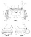
- FIG. 2Ais an isometric view of a mobile lawn mowing robot including an antenna module.
- FIG. 2Bis a bottom view of a mobile lawn mowing robot.
- FIG. 2Cis a back view of a mobile lawn mowing robot.
- FIG. 2Dis a front view of a mobile lawn mowing robot.
- FIG. 2Eis a side view of a mobile lawn mowing robot.
- FIG. 3is a block diagram of computational components of a mobile lawn-mowing robot.
- FIG. 4is a front, cut-away, view of a beacon showing components thereof in block diagram form.
- FIG. 5is a block diagram of a network of devices, including a mobile lawn-mowing robot, a server, a set of beacons, and a user device.
- FIG. 6is an isometric view of an antenna module comprising an antenna assembly and a base assembly.
- FIG. 7is an isometric view of an antenna assembly.
- FIG. 8is an isometric view of antenna assembly components.
- FIG. 9is an exploded isometric view of the antenna assembly components of
- FIG. 8is a diagrammatic representation of FIG. 8 .
- FIGS. 10A and Bpresent calibration layouts for an antenna assembly.
- FIG. 11is a flowchart describing operations of an antenna assembly calibration process.
- Described hereinare example mobile lawn-mowing robots (hereinafter also referred to as robots) configured to traverse mowable surfaces, such as lawns, fields, and other mowable areas, to perform various mowing operations including, but not limited to, cutting grass.
- beaconsthat can communicate with the robots to enable navigation of the robots about the lawns.
- a beaconcan be exclusively paired to one or more robots such that only a robot paired with the beacon can localize to the beacon.
- Such robot and beacon pairingscan be achieved, for example, by using techniques described in U.S. patent application Ser. No. 14/807,485, entitled “Pairing a Beacon with a Mobile Robot” which are incorporated by reference herein in its entirety. After pairing the robots with corresponding beacon sets, the robots can navigate using wideband, ultra-wideband, etc. signals emitted by the paired beacons. Communication operations between the robots and other devices, including beacons, are further described herein.
- FIG. 1Ashows an environment 104 that includes a first lawn 106 and a second lawn 108 .
- First mobile lawn mowing robot 100(referred to as first robot 100 ) is configured to execute mowing operations while navigating around lawn 106 .
- Second mobile lawn mowing robot 102(referred to as second robot 102 ) is configured to execute mowing operations while navigating around lawn 108 .
- Robots 100 , 102each includes a control system, which can include one or more processing devices or controllers that are programmed to control robot operation. Each robot's control system is programmed, for example, to pair the robot 100 , 102 to a corresponding set of beacons.
- robot 100is paired to beacons 110 a , 110 b , and 110 c (beacons 110 ) on first lawn 106
- robot 102is paired to beacons 112 a , 112 b , 112 c , and 112 d (beacons 112 ) on second lawn 108
- Beacons 110 , 112each also includes a control system, which can include one or more processing devices or controllers programmed to control operation of the beacon, including operations to communicate with and pair with robots 100 , 102 .
- pairingincludes establishing a relationship between a robot and its paired beacons so that the robot recognizes, for navigation and localization, signals from the paired beacons only, and not signals from other beacons to which the robot is not paired.
- the robotcan use the signals from its paired beacons to identify the boundary as the robot navigates around the lawn automatically (e.g., without user input).
- robot 100uses beacons 110 to identify the boundary of its lawn 106
- robot 102uses beacons 112 to identify the boundary of its lawn 108 .
- Information about a lawn boundaryis determined during a perimeter teaching operation that a user facilitates. The information is stored in memory in the robot. Together with the beacon signals, the information allows the robot to navigate around the lawn automatically, while not crossing the lawn boundary.
- signals transmitted between a robot and its paired beaconsinclude wideband, ultra-wideband, etc. signals.
- Wideband signalsmay include radio frequency signals having a frequency between 5925 and 7250 MHz.
- the ultra-wideband signalsmay include radio frequency signals having a bandwidth that exceeds 500 MHz, and an operating frequency between 3.1 GHz and 10.6 GHz.
- the usermay need to replace a beacon in the set of beacons or to add a beacon to the set of beacons already assigned to the system.
- the robotuses signals from beacons to accurately estimate its location within the lawn.
- the usermay need to replace a beacon if the beacon becomes damaged or otherwise unusable to ensure that the robot can detect a sufficient number of signals from the beacons during its mowing operations.
- the usermay need to add a beacon to the set of beacons placed on the lawn. For example, as shown in FIG. 1B , during navigation, robot 120 may navigate about a lawn 122 using beacons 124 a , 124 b , 124 c paired to the robot 120 .
- robot 120When robot 120 enters portion 128 of the lawn 122 , robot 120 may be unable to detect or may receive an insufficiently strong signal from the beacon 124 a , which emits a wireless signal 125 that may be blocked or attenuated by a house 126 as the wireless signal 125 travels toward the portion 128 .
- a usermay wish to add a new beacon that can emit a wireless signal detectable by robot 120 in the portion 128 . Adding the new beacon in the portion 126 to the set of beacons 124 a , 124 b , 124 c paired to robot 120 can improve the accuracy of the estimation of the robot's location in the portion 126 .
- second robot 102can be configured such that the second robot 102 does not communicate with beacons with which the second robot 102 is not paired.
- the second robot 102can be configured such that the second robot does not communicate with the first beacons 110 , which are not paired with the second robot 102 .
- first robot 100which is not paired with the second beacons 112 , can be configured such that the first robot 100 does not communicate with the second beacons 112 .
- the environment 104also includes a beacon 114 that is not paired with the first robot 100 or the second robot 102 .
- the beacon 114is in communication range of both robots 100 and 102 (e.g., the robots 100 , 102 can detect wideband, ultra-wideband, etc. signals emitted by the beacon 114 ), and can be paired with either of those robots.
- first robot 100can add the beacon 114 to the set of beacons already paired with the robot 100 .
- Beacon 114can replace an existing beacon or augment the existing beacons to improve localization and navigation of the first robot 100 .
- the robot 100may be unable to detect signals from three beacons at a location on lawn 106 , or the signals from one of the beacons may be weak in that area.
- Beacon 114may be added to that area of the lawn and paired to robot 100 to provide the robot 100 with better beacon signals from that area as described above.
- robots 100 , 102can include systems that allow the robots to navigate through the environment 104 , to perform mowing operations on the lawns 106 , 108 , and to communicate with devices (e.g., the first beacons 110 , the second beacons 112 , and the beacon 114 ), etc.
- the robot 200includes drive wheels 202 a , 202 b drivable by motors (not shown) to maneuver the robot 200 about a surface (e.g. the first lawn 106 , the second lawn 108 ).
- Caster wheels 204 a , 204 b and the drive wheels 202 a , 202 bsupport a chassis 206 of the robot 200 above the surface.
- the robot 200detects contact with obstacles in the environment and determines attributes of that contact, such as a location of the contact with the body of the robot. This object location detection ability allows the robot to automatically select a maneuver, such as a turn, a back up maneuver, etc., to navigate around the obstacle.
- the robot 200includes a shell 208 and an antenna module 210 connected to the chassis 206 .
- the robot 200has a stop button 212 and a lid 230 .
- the lid 230can be opened to access an internal compartment of the robot 200 , which may include an ignition (not shown), etc.
- the robot 200also includes a handle 214 disposed on a rear edge, allowing for a user to manually move the robot 200 for various situations including perimeter training, power failure, etc.
- the robot 200has cutting blades 216 , which are driven by a motor (not shown), for cutting grass.
- the cutting blades 216are mounted on a cutting assembly 218 that is connected to the chassis 206 of the robot 200 .
- the shell 208is connected to the chassis 206 by suspension posts 220 a - 220 d (of which posts 220 a and 220 c are viewable in FIG. 2B ).
- the suspension posts 220 a - 220 dallow the shell 208 to move both laterally (e.g., horizontally) and axially (e.g., vertically) relative to the chassis 206 of the robot 200 .
- the robot 200further includes a battery container 222 in the aft portion of the robot 200 .
- the battery container 222can be removed by pulling a handle 224 in order to service, replace, etc. one or more batteries.
- FIG. 2Ddepicts a front view of the robot 200 .
- FIG. 2Edepicts a side view of the robot 200 .
- FIG. 3depicts a block diagram of systems included in the robot 200 to perform the operations described herein.
- the robot 200includes a controller 226 (e.g., an electronic processor or one or more other appropriate processing devices) that can execute stored instructions to control the navigation, mowing, communication, etc. operations of the robot 200 .
- the controller 226may be disposed at a single location (e.g., a bottom surface of the robot (shown in FIG. 2B ) or distributed among multiple locations.
- a communications system 304 operable with the controller 226can include a wireless transceiver—such as, for example, a wideband, ultra-wideband, etc.
- the communications system 304includes an antenna module (e.g., the antenna module 210 shown in FIG. 2 ). Additional aspects of the communications system including its design, mounting, calibration data, and operation are described herein.
- the robot 200also includes a memory 302 , which is accessible to controller 226 , stores information locally on the robot (e.g., executable instructions, collected data, etc.).
- the beacons described hereininclude systems to implement communications and pairing with a robot.
- FIG. 4is a schematic front view of an example beacon 400 including appropriate systems to support the communications, pairing operations, etc.
- the beacon 400can be attached to a stake 402 that can be placed into a lawn so that the position of the beacon 400 is fixed in the environment.
- the beacon 400can include an adhesive that can be affixed in the outdoor environment to already existing structures (e.g., the side of a house, a fence post, or a tree).
- a controller 404e.g., an electronic processor or one or more other appropriate processing devices
- the communications system 406can include a wireless transceiver that can emit wireless signals, such as wideband, ultra-wideband, etc. signals, into the environment.
- the communications system 406can also use the wireless transceiver to receive wireless signals emitted into the environment by, for example, the robot 200 .
- the controller 404can control the communications system 406 to emit wireless signals for different purposes and functions. For example, during a pairing operation to pair the robot 200 with the beacon 400 , the communications system 406 can be controlled to emit a broadcast that the robot 200 can receive (via the antenna module 210 ) and be identified to initiate pairing operations with the beacon 400 . The communications system 406 can be controlled to transmit a message that the controller 226 of the robot 200 can use to determine a distance between the robot 200 and the beacon 400 . During navigation and mowing operations of the robot 200 , the beacon 400 can emit wireless signals that the robot 200 receives (again via the antenna module 210 ) and uses to localize itself within the environment. A memory 408 that is accessible to the controller 404 permits local storage of information.
- the beacon 400can also include additional portions for other functionality, for example, the beacon can include a replaceable power source 410 (e.g., a battery) that provides power to the various beacon systems.
- the controller 404can monitor a power level of the power source 410 .
- the communications system 406can transmit status updates about the power level of the power source 410 .
- the robot 200 and the beacon 400can be part of a network 500 of devices.
- the devices in the network 500can use one or more wireless protocols, techniques, etc. to communicate with other devices in the network.
- the communications system 304(that includes the antenna module 210 ) of the robot 200 allows the robot to wirelessly communicate with a server 505 , a user device 510 (e.g., a mobile device, a smart phone, a computer, etc.), and the beacon 400 .
- the network 500can also include other beacons 515 paired with the robot 200 .
- the communications system 304can communicate with the server 505 using, for example, a Wi-Fi transceiver in communication with the antenna module 210 .
- the communications system 304can also communicate with the communications system 406 of the beacon 400 using wideband, ultra-wideband, etc. signals.
- the network describedincludes a robot, a beacon set, a server, and a user device, it will be appreciated additional devices may be included in the network by employing one or more communication techniques (e.g., RF communication).
- the memory 302 of the Robot 200 and the memory 408 of the beacon 400can store various information transmitted through the network 500 .
- the memory 302can store a robot address 520 unique to the robot 200 .
- the robot address 520is a unique identifier (e.g., a serial number) for the robot 200 that can be sent with wireless signals (e.g., wideband, ultra-wideband signals, etc.) transmitted by the communications system 304 (e.g., using the antenna module 210 ).
- the memory 408 of the beacon 400when the robot 200 is paired with the beacon 400 , can also store the robot address 520 . By storing the robot address 520 , the memory 408 enables the beacon 400 to be uniquely paired to the robot 200 .
- the memory 408 of the beacon 400stores a beacon address 525 unique to the beacon 400 . Similar to the robot address 520 , the beacon address 525 is a unique identifier for the beacon 400 .
- the beacon 400can transmit the beacon address 525 with wireless transmissions of its communications system 406 .
- the memory 302can store the beacon address 525 .
- the memory 408can enable the beacon 400 to be paired to the robot 200 such that other robots cannot pair to the beacon 400 .
- the memory 302enables the robot 200 to be paired to the beacon 400 such that, during navigation and mowing operations, the robot 200 can communicate with the beacon 400 .
- the robot 200 and the beacon 400can also both store a predefined address that is not specific to any beacon or robot.
- the communications system 304 and the communications system 406can communicate with one another using the predefined address prior to the robot 200 receiving the beacon address 525 and the beacon 400 receiving the robot address 520 .
- a passcode 530can be stored in both the memory 302 of the robot 200 and the memory 408 of the beacon 400 .
- the passcode 530may be entered into, for example, a user interface of the other robot to allow the other robot to pair with the beacon 400 .
- calibration data 550can be stored for later retrieval and application to collected signals.
- Calibration data 550can represent various parameters for signal correction, for example, ranging and angular calibration data can be stored and retrieved to account of position offsets (e.g., antenna element spacing), angles (e.g., antenna element orientation), etc.
- position offsetse.g., antenna element spacing
- anglese.g., antenna element orientation
- the calibration data 550is presentable on the user interface 545 for inspection, trouble-shooting, etc.
- the calibration data 550is transferrable to other components of the network 500 of devices (e.g., provided to the user device 510 , server 505 , etc.).
- the calibration data 550may also be provided to one or more of the paired beacons for storage, comparison with other calibration data, maintenance issues, etc.
- the other beacons 515form part of a set of beacons already paired with the robot 200 .
- these beaconsmay have been previously paired to the robot by a user or during manufacture of the robot and beacons.
- the other beacons 515each include a beacon address.
- Each of the other beacons 515includes a memory to store its unique beacon address.
- the memory 408can store beacon addresses 535 of the other beacons 515 so that the other beacons are exclusively paired to the robot 200 .
- the controller 226can cause the communications system 304 to propagate the beacon addresses 535 to each of other beacons paired to the robot 200 .
- the memories of the other beacons 515 and the memory 408 of the beacon 400can also store the other beacon addresses 535 .
- the memories of the other beacons 515can also store the passcode 530 .
- the server 505can store the robot address 520 , the beacon address 525 , the passcode 530 , and the other beacon addresses 535 in memory storage associated with a user account 540 .
- the robot 200can communicate the information stored in the user account 540 by communicating with the server 505 using the communications system 304 .
- the information stored in the user account 540can serve as a backup to storage elsewhere on the network.
- the usercan interact with the user interface 545 .
- the user interface 545may include, but is not limited to, the stop button 212 , an array of light indicators, and an array of buttons to control the operations of the robot 200 , etc.
- the user device 510can communicate with the communications system 304 of the robot 200 using, for example, a Bluetooth, a Wi-Fi, etc. connection or may employ one or more other types of electromagnetic communications (e.g., using the antenna module 210 , a laser based system, etc.).
- the usercan additionally or alternatively use the user device 510 to view information and enter information pertaining to the operations of the robot 200 .
- the usercan invoke the user interface 545 and/or the user device 510 to, for example, confirm various operations associated with pairing the robot 200 with the beacon 400 and enter the passcode 530 to allow for pairing to occur.
- the usercan also use the user interface 545 of the robot 200 or the user device 510 to view and respond to errors and requests transmitted by the communications system 304 of the robot 200 .
- FIGS. 6, 7, 8 , and- 9depict physical aspects of the robot communications system 304 , in particular the antenna module 210 , and functionality provided thereby.
- the communications system 304enables the controller 226 (shown in FIG. 3 ) to exchange signals with the various devices on the network 500 , which may include the beacon set 515 , the server 505 , and the user device 510 (as shown in FIG. 5 ).
- the antenna module 210(of the communication system 304 ) is presented and includes an antenna assembly 612 mounted to a base assembly 600 .
- the antenna assembly 612connects to the base assembly 600 through an interference fit with an array of fins 606 disposed on the base assembly 600 .
- the fins 606provide support, strength, and reduce complexity for injection-molded tooling.
- a cable harness or similar mechanismcan be inserted through one or more of the fins to assist with support.
- the array of fins 606serves to mechanically isolate the electronic connections between the antenna assembly 612 and the base assembly 600 .
- One or more materialsmay be employed to produce the fins (e.g., one or multiple plastics).
- the base assembly 600includes an electronic interface 610 , which connects to the controller 226 of the robot 200 .
- the electronic interface 610enables signal received from the antenna assembly 612 to be provided to the controller 226 , and allows the controller 226 to provide signals to the antenna assembly 612 for transmission.
- the base assembly 600attaches to a rear portion of the chassis 206 via mounting posts 608 a, b, c, d .
- Such mountingallows the antenna module 210 to be removed from one robot and attached to another robot. Along with transferring its capability from one robot to another, removal of the antenna module 210 may be warranted for other operations (e.g., service module components, perform a calibration operations, etc.).
- FIG. 7presents a view of the antenna assembly 612 .
- a housing 602protects the internal hardware of the antenna assembly 612 along with providing other functionality (e.g., provides a radome for antenna elements so incident waves and transmitted waves can propagate through the radome material with appropriate levels of reflection and loss).
- a spring 604is disposed below the housing 602 and interfaces with the mounting fins 606 of the base assembly 600 ( FIG. 6 ). In general, the spring 604 provides a flexible coupling that allows the assembly 612 to be deflected (e.g., up to 90 degrees in any direction), for example, upon encountering one or more obstacles in the yard that are not detected by a bumper sensor of the robot 200 .
- the spring 604also provides other functionality such as returning the antenna assembly 612 to a calibrated position with respect to a coordinate system of the robot (e.g., Cartesian coordinate system) upon disengaging with the obstacle(s). Such functionality allows relatively high antenna heights to be realized without considerable impairment to mobility.
- the spring 604is coupled to the mounting fins 606 through a threaded interface to reduce the probability of decoupling of the parts.
- a threaded interface arrangementcan cause the coil of the spring to tighten due to the winding direction of the spring; for example, when being unscrewed from the threaded interface.
- the housing 602may include external component, for example an array of light indicators configured to give visual alerts to a user.
- One or more components of the robot 200can be employed for setting antenna height.
- the spring 604can be used to position the antenna assembly at a reasonable height for signaling operations (e.g., provide sufficient line of site for communications with beacons and other devices) while not extending to a height that could hinder operations of the robot (e.g., hinder mowing operations by having the antenna assembly 612 getting tangled in low-hanging tree or bush branches).
- the top of the housing 602can have a height between 400 mm and 500 mm (e.g., 436 mm) above the surface (e.g., the ground) that the robot 200 is positioned.
- Dimensions of the housing 602may also assist in performing such operations, for example, the cylindrical shaped housing can have an outer diameter between 30 mm to 50 mm (e.g., 35 mm). In some arrangements the outer diameter may exceed 50 mm.
- Characteristics of the spring 604may also be set to provide operational assistance.
- the spring 604can be preloaded to ensure that the antenna assembly 612 does not sway or move during normal operation of the robot 200 , but will bend down if a force (larger than the preload) acts upon the spring.
- the force required to overcome the preloadcan range between 0.5 N to 2.5 N, for example 1 N.
- one or more antenna layoutscan be employed to achieve design objectives, as illustrated by the components of the antenna assembly 612 shown in the figure.
- multiple antenna elementsmay be included the housing 602 for identifying the angle of arrival (AOA) of an incident electromagnetic wave.
- the antenna elements employedcan allow for the three dimensional (3D) AOA to be determined to assist with identifying particular sources (e.g., a paired beacon), ranging to a source, etc.
- antenna elementsare positioned to form a tetrahedral geometry in which three antenna elements define the base of the tetrahedral and a central antenna element is positioned above the base.
- FIG. 9provides an exploded view of the 3D RF AOA system 800 included in the antenna assembly 612 .
- three antenna elements 804 a , 804 b , and 804 c(referred to as angle antennas) provide the base of the tetrahedral and are axisymmetrically position around another antenna element 802 (referred to as the ranging antenna), which is positioned above the triangular base of antenna elements 804 a , 804 b , and 804 c .
- the three antenna elements 804 a , 804 b , and 804 care used to receive signals to determine AOA while the ranging antenna element 802 is used to determine range.
- Employing such a tetrahedral geometry with four antenna elementsremoves ambiguity in determining the angle of arrival of an incident wave (which can be experienced when using less antenna elements such as a two-element system).
- the top of the ranging antenna 802can have an approximate height between 375 mm and 475 mm (e.g., 413 mm) above the surface that the robot is positioned.
- the height of each of the three angle antennas 804 a , 804 b , and 804 ccan be between 360 mm and 460 mm (e.g., 396 mm).
- the 3D RF AOA system 800includes a holder 812 comprising an upper portion 806 and a lower portion 808 .
- the upper portion 806 of the holder 812is designed to hold the main antenna 802 .
- the geometry of the upper portion 806allows the main antenna 802 to be installed by snapping the main antenna into place.
- the main antenna 802employs a rectangular slot antenna design and the holder 812 is produced from plastic, however, other materials or combinations of materials may be used to produce the components of the 3D RF AOA system.
- acrylic-styrene-acrylonitrile (ASA) polymers or other types of amorphous plasticsare employable for producing the structures of the 3D RF AOA system, the antenna assembly 612 , the base assembly 600 , etc.
- One or more portions of the housing 602e.g., a radome portion of the housing
- the upper portion 806 of the holder 812 , the lower portion 808 of the holder 812 , etc.can include a thin-walled polypropylene or one or more other materials that have properties for appropriate electromagnetic wave propagation.
- each angle antennais held in place by a respective plastic finger 900 a - 900 c , each positioned to form the base of the tetrahedral geometry and oriented to reduce blocking the reception of the other antenna elements, reduce incident wave reflections, etc.
- a reduced amount of materialscan be used to produce the portions of the holder 812 (e.g., thickness of the fingers 900 a - c ) to reduce incident wave reflections.
- Materialscan be selected for attempting to match free space impedance (e.g., select materials with appropriate permeability and permittivity) to reduce reflections and thereby reduce system measurement error.
- the three angle antennas 804 a - 804 care axisymmetrically arranged around the ranging antenna 802 to form a tetrahedral shape with the vertices of the tetrahedron defined by the tip of each antenna.
- the separation distance between each of the four antennas 802 , 804 a - 804 cis chosen to be less than one half wavelength of the communication system operating frequency. For example, in some implementations, an equal distance separates each pair of antenna elements.
- Using a separation distance between 0.5 and 1.5 cmcorresponds to operating frequencies between 10 and 30 GHz, however, other separation distances may be used for operating frequencies in high or lower radio communication bands (e.g., 6.5 GHz, between 5925 MHz and 7250 MHz, etc.). While some implementations can used unequal separation distances between the antenna elements, typically one common separation distance is used to define the tetrahedral geometry. Setting the antenna separation distance to be less than one half wavelength also allows phase differences (measured at two antenna elements) to be determined without phase wraparound. For systems that employ techniques to account for wraparound of measured phases, antenna separation may be increased to distances larger than one half wavelength.
- This element tetrahedral geometryremoves the directional ambiguity by measuring incident waves with four antenna elements rather than two elements. Once measured, techniques such as time difference of arrival (TDOA), phase difference of arrival (PDOA), etc. can be executed individually or in combination to determine the angle of arrival of the incident wave absent ambiguity.
- TDOAtime difference of arrival
- PDOAphase difference of arrival
- additional informationcan be collected to determine the orientation of the tetrahedron geometry of the antenna elements relative to other geometries.
- the orientation of the AOA system 800 relative to the geometry of the beaconscan be determined from a range measure between the AOA system 800 and one or more beacons. With the range(s) determined, a location of the AOA system 800 based on the location(s) of the beacon(s) can be determined.
- One or more techniquesmay be employed to determine such a range; for example, circuitry (e.g., a DW1000 low power single chip radio transceiver from DecaWave of Dublin, Ireland) may be incorporated into the communications system 304 of robot 200 , one or more beacons, etc.
- the range between the devicescan be determined.
- a DW1000 chipis incorporated into each antenna module (e.g., a DW1000 chip is incorporated for each of the antenna elements 802 , 804 a - 804 c , for a total of four DW1000 ICs).
- the angle of arrival informatione.g., from the phase difference of arrival for the four antenna elements 802 , 804 a - 804 c
- a distinct orientation of the tetrahedron configurationcan be determined in 3D space with reference to the location of a transmitting node (for example, the beacon 400 ).
- the 3D RF AOA system 800enables the robot 200 to receive and transmit wireless signals in one or more frequency bands (e.g., high frequency (HF), very high frequency (VHF), extremely high frequency (EHF), etc.), use one or more radio technology techniques (e.g., wide band, ultra-wideband, etc.), protocols (e.g., wireless protocols such as Wi-Fi, Bluetooth, etc.), etc.
- HFhigh frequency
- VHFvery high frequency
- EHFextremely high frequency
- radio technology techniquese.g., wide band, ultra-wideband, etc.
- protocolse.g., wireless protocols such as Wi-Fi, Bluetooth, etc.
- the wide range of devices the 3D RF AOA system 800 can communicate withallows for a wide range of applications.
- the robot 200is able to receive and transmit signals to communicate with a beacon (e.g., beacon 400 ) or a set of beacons (e.g., beacons 515 ) in order to pair the robot 200 and the one or more beacons, thereby creating an exclusive interaction between the paired devices.
- the robot 200is able to receive and transmit signals to communicate with one or more beacons to determine the location of the robot 200 .
- the 3D RF AOA system 800is able to uniquely solve for the location of the robot 200 in 3D space in reference to the transmitting beacon. The accuracy of the calculated location can be improved through performing similar operations with a set of beacons (e.g., beacon set 515 ) arranged throughout a mowable surface.
- location determination of the robot 200can include using information from a movement sensor that generates movement signals indicative of a distance travelled by the robot, a speed of the robot, an acceleration of the robot, etc.
- a movement sensorcan also detect relative rotations around one or more axes (e.g., an inertial measurement unit (IMU)).
- the controller 226can use the movement signals to perform Simultaneous Localization and Mapping (SLAM) techniques that the robot 200 can use, in addition to the beacon-based localization techniques, to estimate its position within the environment. Based on the movement signals and/or other collected information (e.g., from one or more beacons), the controller 226 can generate a map of the environment and determine the pose of the robot.
- SLAMSimultaneous Localization and Mapping
- the movement signalscan include data from, for example, encoders associated with a drive of the robot, an optical mouse sensor, an IMU, an accelerometer, a gyroscope disposed on the robot, etc.
- the data of the movement signalscan be used as dead reckoning data that the controller 226 uses to determine relative positions of the robot.
- the controller 226using the movement signals, can determine a relative position of the robot 200 measured relative to previous positions of the robot. Accurate over relatively short distances, dead reckoning can be prone to drift errors that accumulate over time. Accumulated drift can affect both the distance computations and the heading computations.
- the robot 200can provide other types of functionality, for example, the module could include a GPS receiver for robot communicating (e.g., with radio frequency signals) to communicate with a GPS satellite network for determining the global position of the robot. Once attained, the GPS information can be used to determine the global position of the robot in addition to its relative position on a mowable surface. Along with position information, wireless signals can be used for transmitting and receiving other types of information.
- the robot 200can use the antenna module 210 to send status information, maintenance alerts, etc.
- the robot 200can wirelessly receive information from one or more beacons regarding beacon status (e.g., battery life), maintenance alert, etc.
- Communications with the robot 200can also include one or more computing devices (e.g., servers, mobile devices, computer systems, etc.) for exchanging information.
- informationcan be exchanged between the robot 200 and the server 505 (shown in FIG. 5 ) regarding the user account 540 , etc.
- Various types of informationmay be transmitted, for example, images, video, audio, etc., can be collected and exchanged among devices (e.g., the robot 200 , the server 505 , the beacons, other computing devices, etc.).
- One or more commands, instructional data, etc.may be exchanged between a computing device (e.g., the user device 510 shown in FIG. 5 ) and the robot 200 .
- One or more network architectures and network devicesmay establish communications with the robot 200 ; for example, the robot 200 can receive and transmit RF signals to communicate with a variety of objects connected to the Internet of Things (IoT).
- the robot 200can communicate with the IoT such that robot operations are halted if an individual (e.g., a child) is in the vicinity, the robot 200 can communicate with IoT to coordinate operations with a sprinkler system, etc.
- the robot 200can receive and transmit RF signals to communicate with other robots (e.g. robot 100 or robot 102 ).
- Other network based applicationscan also be initiated by establishing such communications, for example, a network (e.g., a mesh network) can be established among the multiple robots to exchange data among the robots, other devices connected to the network, etc.
- the 3D RF AOA systemcan be calibrated to accurately output a calculated position of the robot 200 relative to one or more transmitting nodes (e.g. beacon 400 ).
- a transmitting nodese.g. beacon 400
- techniquesmay be employed for calibrating AOA measurements to accurate provide azimuth and elevation angles.
- One or more set-upsmay be employed to calibrate the system; for example, a radio frequency source can transmit calibration signals towards the antenna module 210 as the source travels along a circular path at the center of which the antenna module is positioned.
- a radio frequency sourcecan transmit calibration signals towards the antenna module 210 as the source travels along a circular path at the center of which the antenna module is positioned.
- a radio frequency sourceis positioned in a stationary location (e.g., e.g., in a compact range, an anechoic chamber, etc.) and the antenna module 210 is rotated about an axis to present each aspect to the source.
- the antenna module 210is mounted to the robot 200 and is rotated (clockwise or counter-clockwise) about an axis 1000 .
- a turntable 1002rotates to present the different aspects of the antenna module 210 , which is centered on the axis 1000 so each azimuthal aspect of the antenna module is present at the same distance from the radio frequency source.
- the radio frequency sourcecan adjusted so incident signals are transmitted at different elevation angle (e.g., signal 1004 is presented at a positive elevation angle, signal 1006 is presented with zero elevation angle, signal 1008 is presented with a negative elevation angle).
- signals with different elevation anglescan be transmitted towards the antenna module 210 to collect different data sets for calibrating the 3D RF AOA system.
- the antenna module 210can be calibrated absent the robot 200 .
- the antenna module 210is rotated about an axis 1010 (e.g., counter-clockwise) by a turntable 1012 to azimuthally present different aspects to a radio source that transmits signals at a particular elevation angle (e.g., a positive elevation angle signal 1014 , a zero elevation angle signal 1016 , a negative elevation angle signal 1018 ).
- a particular elevation anglee.g., a positive elevation angle signal 1014 , a zero elevation angle signal 1016 , a negative elevation angle signal 1018 .
- Various techniquescan be employed for calibrating the 3D AOA system, for example, a collection of three techniques may be utilized. For example, one calibration technique can be employed to address less than optimal positioning for the antenna elements contained in the antenna module. Along with this calibration, two techniques can be employed to address distortion; a first distortion correction technique (referred to as input correction) applies calibration values from the initial calibration technique (regarding antenna element positioning) to measured data. A second distortion correction technique (referred to as output correction) accounts for differences between expected phase values (to be received from the radio frequency source signals) and the measured phase values.
- input correctionapplies calibration values from the initial calibration technique (regarding antenna element positioning) to measured data.
- a second distortion correction technique(referred to as output correction) accounts for differences between expected phase values (to be received from the radio frequency source signals) and the measured phase values.
- the phase difference between a pair of antenna elementscan be measured as the antenna module 201 is rotated about the turntable 1010 ).
- the measured phase difference between these two elementsshould be a sine wave.
- the measured phase differencecan differ from the expected (or ideal) phase difference. For example, amplitude differences (between the sine waves representing measured and expected phase differences) represents an error in distance between the two antenna elements.
- a phase difference(again between the sine waves representing the measured and expected phase differences) represents an error in angle between the two antenna elements.
- An offset between the two sine wavesrepresents an error in the height difference in the two antenna elements.
- a non-zero average of the measured phase difference between the pair of antenna elementsrepresents an offset in the phase difference of arrival of the signals.
- Such calibration quantitiescan be determined for incident signals transmitted for different elevation angles. For example, along with determining the calibration quantities for a zero-elevation angle signal (e.g., signal 1016 ), calibration quantities can be determined for one or more signals with positive elevation angle signals (e.g., signal 1014 ) and for negative elevation angle signals (e.g., signal 1018 ). In some arrangements, interpolation techniques can be employed to attain calibration quantities for elevation angles that are not included in the measurements.
- distortion correction techniquesBy identifying these differences between the expected and measured, quantities can be determined to apply to signals received at the antenna module when mounted to the robot under operation.
- Such corrections applied to signals collected during robot operationsare referred to as distortion correction techniques.
- two distortion techniquesare employed, a first referred to as an input distortion correction technique and a second referred to as an output distortion correction technique.
- the output distortion correction techniquephase difference of arrival (pdoa) signals are measured from one or more pairs of antenna elements in the antenna module 210 .
- An inverse mapis created from interpolated ground truth data, and the map is used to provide corrected azimuth and elevation.
- the input distortion correction techniquea map is created for translating ideal pdoa signals to measured pdoa signals.
- An inverse mapis created for mapping from pdoa signals to ideal pdoa signals. Once created, the inverse map is stored and later retrieved to map pdoa signals (measured during robot operation) to the ideal pdoa signals. From this mapping, azimuth and elevation angles are calculated and returned.
- the phase difference of arrival between the three angle antennas 804 a - 804 c to the ranging antenna 802provides both azimuth and elevation angles of the incoming signal. If the transmitter orbits the axis of the ranging antenna 802 , or if the 3D RF AOA system 800 is rotated around this axis, the ideal response in the phase difference of arrival (pdoa) is a sine wave. The real response is only an approximation of a sine wave, and the process of calibrating the 3D RF AOA system 800 involves mapping the real response to the ideal response in order to output an accurate azimuth and elevation of the incoming signal.
- FIG. 11is a flowchart of an example process 1100 for computing one or more calibration parameters associated with a pair of antennas disposed on a mobile robot.
- the process 1100can be executed at the antenna module 210 described above.
- the operations of the process 1100can be executed for each pair of antennas in the antenna module 210 (e.g., a pair including the ranging antenna 802 and one of the angle antenna 804 a - 804 c , a pair including two of the angle antenna 804 a - 804 c , etc.).
- Operations of the process 1100includes receiving, by each of the pair of antennas for each of a plurality of locations of the pair of antennas relative to a transmitter, a wireless signal generated by the transmitter ( 1102 ).
- the pair of antennascan be kept static, and the transmitter can be moved to a plurality of locations at various azimuth angles with respect to the antenna array.
- the transmittercan be kept static, and the pair of antennas can be rotated (e.g., relative to one another) to obtain the plurality of locations of the pair of antennas relative to the transmitter.
- Operations of the processalso includes determining, a phase difference of arrival (PDOA) of the wireless signal between the two antennas for each of the plurality of locations to obtain a set of PDOA values ( 1104 ).
- PDOAphase difference of arrival
- the pair of antennas(which may also be referred to as an antenna array) is rotated with respect to a fixed transmitter to multiple locations at a fixed elevation angle (e.g., substantially zero elevation), and the PDOA values for each of the locations are collected to obtain the set of PDOA values.
- the expected variation of the PDOA values, as the pair of antennas or the transmitter moves in a substantially circular path relative to one anothercan be represented by a periodic signal such as a sine wave.
- Operations of the process 1100also includes computing the one or more calibration parameters based on the set of PDOA values ( 1106 ). For example, if the set of PDOA values are expected to vary in a sinusoidal pattern, the obtained PDOA values are fit to a sine wave, which is then used to find the calibration parameters. For example, an average or mean of the set of PDOA values may represent the reference level of a sine wave, and therefore represent an offset associated with the set of PDOA values.
- the one or more calibration parameterscan be of various types.
- one or more calibration parameterscan include a distance offset between the two antennas in the pair along a plane on which the antennas are disposed. In such cases, the distance offset may be computed based on an amplitude of the function that represents the set of PDOA values.
- calibration parameterscan account for an angle offset between the two antennas in the pair along a plane on which the antennas are disposed. In such cases, the angle offset may be computed based on a phase of a function that represents the set of PDOA values.
- the amplitude of the sine wavecan be proportional to the distance between the antennas in the x-y plane, and the phase of the sine wave gives the relative angle of antennas in the x-y plane.
- the one or more calibration parametersinclude a vertical offset between the two antennas.
- the vertical offsetcan be the distance between the two antennas in the pair along a direction perpendicular to the plane on which the antennas are disposed. This can be calculated, for example, by rotating the pair of antenna and transmitter relative to one another at a non-zero elevation, and obtaining the PDOA values for the corresponding plurality of locations. The vertical offset can then be calculated by comparing the vertical shift between the function representing the PDOA values at the non-zero elevation, and the function representing the PDOA values at the zero elevation.
- the vertical shift between sine wavescan represent the vertical offset (or the distance in the z direction) between the two antennas.
- the distance offset, angle offset, and the vertical offset between the antennascan be represented using Cartesian coordinates x, y, and z, respectively.
- the calibration outputsmay be affected by distortions inherent in the system.
- distortionscan be introduced in the wireless signal as the signal travels the medium between the transmitter and the antennas.
- Such distortionsmay cause the PDOA variations to deviate from the expected pattern, and/or have undesirable statistical qualities such as zero mean.
- such distortionsmay be corrected using one or more pre-computed correction parameters that are determined, for example, by comparing a particular set of PDOA responses to a ground truth or ideal response that may be available for the medium.
- the distortion correctionis performed on the calculated calibration parameters.
- the calibration parameters corresponding to the azimuth and elevationare calculated from PDOA values as described above, and the calculated calibration parameters are then corrected for distortions using, for example, a look-up table, correction map, etc.
- the correction mapcan be generated by measuring PDOA data under a controlled setting (e.g., by rotating an antenna array over a 360 degree range of azimuth angles), interpolating available ground truth data to smooth out the distribution of the measured PDOA data, and mapping the ground truth to the measured PDOA.
- An inverse mapcan then be created by mapping the measured PDOA to ground truth. This can then be stored as a look-up table, correction map, etc. for use in correcting calibration parameters during run time.
- the distortion correctionis performed on the PDOA values prior to using the PDOA values for calculating the calibration parameters.
- corrected PDOA valuesare generated using correction parameters pre-computed using ground truth data on PDOA values.
- the correction parameterscan be stored, for example, in the form of a look-up table or correction map.
- such a correction mapcan be generated by measuring PDOA data under a controlled setting (e.g., by rotating an antenna array over a 360 degree range of azimuth angles), interpolating the available ground truth data to smooth out the distribution of the measured PDOA data, and mapping the ideal PDOA data to the measured PDOA data.
- An inverse correction mapcan then be created by mapping the measured PDOA data to the ideal PDOA data.
- Such an inverse mapcan be stored as a look-up table, and used for looking up a corrected PDOA value corresponding to a measured PDOA value.
- the calibration parameters for the azimuth and elevation anglescan then be calculated using the corrected PDOA value.
- the examples described hereincan be implemented in a variety of ways without departing from the scope of the specification. While a single robot has been described to pair with a set of beacons, the robot can also be configured to pair with multiple sets of beacons. In such cases, the robot can maintain multiple different lawns. Each lawn may contain a different set of beacons which will also have a different map associated with it. The user may select one of the stored maps to use during a mowing operation such that the user can select between the various sets of beacons paired with the robot.
- the robot 200can include a user interface 545 that can receive user interface data from the controller 226 to display information pertaining to the operations of the robot 200 . Therefore, the user, in addition or as an alternative to using the user device 510 , can view the information on a user interface 545 of the robot 200 and can interact with the user interface 545 to control operations of the robot 200 . For example, the user can use the user interface 545 to confirm the pairing between the robot 200 and the beacon 400 .
- a set of beaconscan include three or more beacons, as described in some implementations herein. In some cases, the set of beacons can include fewer than three beacons.
- the robotcan navigate using the signals emitted from the set of beacons including fewer than three beacons and can use on-board movement sensors to also execute dead reckoning processes to improve accuracy of its estimate of its location.
- the robots described hereincan be controlled, at least in part, using one or more computer program products, e.g., one or more computer programs tangibly embodied in one or more information carriers, such as one or more non-transitory machine-readable media, for execution by, or to control the operation of, one or more data processing apparatus, e.g., a programmable processor, a computer, multiple computers, and/or programmable logic components.
- one or more computer program productse.g., one or more computer programs tangibly embodied in one or more information carriers, such as one or more non-transitory machine-readable media, for execution by, or to control the operation of, one or more data processing apparatus, e.g., a programmable processor, a computer, multiple computers, and/or programmable logic components.
- a computer programcan be written in any form of programming language, including compiled or interpreted languages, and it can be deployed in any form, including as a stand-alone program or as a module, component, subroutine, or other unit suitable for use in a computing environment.
- Operations associated with controlling the robots described hereincan be performed by one or more programmable processors executing one or more computer programs to perform the functions described herein. Control over all or part of the robots described herein can be implemented using special purpose logic circuitry, e.g., an FPGA (field programmable gate array) and/or an ASIC (application-specific integrated circuit).
- special purpose logic circuitrye.g., an FPGA (field programmable gate array) and/or an ASIC (application-specific integrated circuit).
- processors suitable for the execution of a computer programinclude, by way of example, both general and special purpose microprocessors, and any one or more processors of any kind of digital computer.
- a processorwill receive instructions and data from a read-only storage area or a random access storage area or both.
- Elements of a computerinclude one or more processors for executing instructions and one or more storage area devices for storing instructions and data.
- a computerwill also include, or be operatively coupled to receive data from, or transfer data to, or both, one or more machine-readable storage media, such as mass PCBs for storing data, e.g., magnetic, magneto-optical disks, or optical disks.
- Machine-readable storage media suitable for embodying computer program instructions and datainclude all forms of non-volatile storage area, including by way of example, semiconductor storage area devices, e.g., EPROM, EEPROM, and flash storage area devices; magnetic disks, e.g., internal hard disks or removable disks; magneto-optical disks; and CD-ROM and DVD-ROM disks.
- semiconductor storage area devicese.g., EPROM, EEPROM, and flash storage area devices
- magnetic diskse.g., internal hard disks or removable disks
- magneto-optical diskse.g., CD-ROM and DVD-ROM disks.
Landscapes
- Engineering & Computer Science (AREA)
- Physics & Mathematics (AREA)
- General Physics & Mathematics (AREA)
- Radar, Positioning & Navigation (AREA)
- Remote Sensing (AREA)
- Computer Networks & Wireless Communication (AREA)
- Manipulator (AREA)
- Robotics (AREA)
- Mechanical Engineering (AREA)
- Aviation & Aerospace Engineering (AREA)
- Automation & Control Theory (AREA)
- Control Of Position, Course, Altitude, Or Attitude Of Moving Bodies (AREA)
Abstract
Description
Claims (20)
Priority Applications (1)
| Application Number | Priority Date | Filing Date | Title |
|---|---|---|---|
| US15/435,058US10459063B2 (en) | 2016-02-16 | 2017-02-16 | Ranging and angle of arrival antenna system for a mobile robot |
Applications Claiming Priority (2)
| Application Number | Priority Date | Filing Date | Title |
|---|---|---|---|
| US201662295832P | 2016-02-16 | 2016-02-16 | |
| US15/435,058US10459063B2 (en) | 2016-02-16 | 2017-02-16 | Ranging and angle of arrival antenna system for a mobile robot |
Publications (2)
| Publication Number | Publication Date |
|---|---|
| US20170234961A1 US20170234961A1 (en) | 2017-08-17 |
| US10459063B2true US10459063B2 (en) | 2019-10-29 |
Family
ID=59562075
Family Applications (1)
| Application Number | Title | Priority Date | Filing Date |
|---|---|---|---|
| US15/435,058Active2037-10-16US10459063B2 (en) | 2016-02-16 | 2017-02-16 | Ranging and angle of arrival antenna system for a mobile robot |
Country Status (1)
| Country | Link |
|---|---|
| US (1) | US10459063B2 (en) |
Families Citing this family (16)
| Publication number | Priority date | Publication date | Assignee | Title |
|---|---|---|---|---|
| US10459063B2 (en) | 2016-02-16 | 2019-10-29 | Irobot Corporation | Ranging and angle of arrival antenna system for a mobile robot |
| US11290323B2 (en) | 2017-04-13 | 2022-03-29 | Qualcomm Incorporated | Configuring multi-channel transmission for ranging accuracy |
| US10942249B2 (en)* | 2017-12-22 | 2021-03-09 | Nxp B.V. | Method and system for determining a location of a mobile device |
| CN111324111B (en)* | 2018-12-13 | 2022-11-01 | 苏州科瓴精密机械科技有限公司 | Method for recognizing boundary signal and robot system |
| KR102649597B1 (en)* | 2019-01-02 | 2024-03-20 | 한국전자통신연구원 | Method for determining location information of signal source using unmaned vehicle and apparatus for the same |
| CN110740505B (en)* | 2019-10-18 | 2024-11-22 | 深圳市微能信息科技有限公司 | Positioning circuit, positioning system and positioning method based on Bluetooth AOA communication |
| DE102020000339A1 (en) | 2020-01-17 | 2021-07-22 | Asmar Jungblut | Location system |
| EP4103365B1 (en)* | 2020-02-13 | 2025-04-02 | Jabil Inc. | Apparatus, system, and method for a phased array antenna for an autonomous robot |
| US11262430B2 (en)* | 2020-06-16 | 2022-03-01 | Silicon Laboratories Inc. | Positioning and self-calibration mechanism using moving AoA locator |
| US11456530B2 (en) | 2020-06-16 | 2022-09-27 | Silicon Laboratories Inc. | Positioning and self-calibration mechanism using moving AoA locator |
| KR20220018174A (en)* | 2020-08-06 | 2022-02-15 | 엘지전자 주식회사 | Mowing Robot |
| CN114355283A (en)* | 2020-10-14 | 2022-04-15 | Oppo广东移动通信有限公司 | UWB module calibration method, device, electronic equipment and storage medium |
| CN114545322A (en)* | 2020-11-26 | 2022-05-27 | Oppo广东移动通信有限公司 | Method, device and equipment for determining angle of arrival (AOA) and storage medium |
| EP4327989A4 (en) | 2021-10-13 | 2024-12-04 | Samsung Electronics Co., Ltd. | MOBILE ROBOT |
| WO2024074200A1 (en)* | 2022-10-05 | 2024-04-11 | HELLA GmbH & Co. KGaA | Distance determination between two bluetooth devices |
| CN116505992B (en)* | 2023-06-25 | 2023-09-15 | 西安安森智能仪器股份有限公司 | Wireless communication method |
Citations (335)
| Publication number | Priority date | Publication date | Assignee | Title |
|---|---|---|---|---|
| US2751030A (en) | 1952-11-13 | 1956-06-19 | Null Fay Edison | Light sensitive automatically controlled steering system |
| US3128840A (en) | 1962-04-23 | 1964-04-14 | Barrett Electronics Corp | Random control for power-driven unit |
| US3385041A (en) | 1965-08-31 | 1968-05-28 | Donald R. Douglas | Comb attachment for lawnmowers |
| US3457575A (en) | 1965-12-23 | 1969-07-29 | Bissell Inc | Sweeper for carpeted and smooth floors |
| US3550714A (en) | 1964-10-20 | 1970-12-29 | Mowbot Inc | Lawn mower |
| US3674316A (en) | 1970-05-14 | 1972-07-04 | Robert J De Brey | Particle monitor |
| US3924389A (en) | 1973-03-27 | 1975-12-09 | Stanley B Kita | Automatic lawn mower |
| US3937174A (en) | 1972-12-21 | 1976-02-10 | Hermann Haaga | Sweeper having at least one side brush |
| US3946543A (en) | 1971-12-10 | 1976-03-30 | Templeton William E | Power mower with hydraulic drive |
| US4119900A (en) | 1973-12-21 | 1978-10-10 | Ito Patent-Ag | Method and system for the automatic orientation and control of a robot |
| US4133404A (en) | 1975-04-25 | 1979-01-09 | Agile Systems, Inc. | Automatic lawn mower |
| US4163977A (en) | 1977-12-21 | 1979-08-07 | Polstorff Jurgen K | Double loop receiver-transmitter combination |
| US4306329A (en) | 1978-12-31 | 1981-12-22 | Nintendo Co., Ltd. | Self-propelled cleaning device with wireless remote-control |
| US4328545A (en) | 1978-08-01 | 1982-05-04 | Imperial Chemical Industries Limited | Driverless vehicle autoguide by light signals and two directional detectors |
| US4369543A (en) | 1980-04-14 | 1983-01-25 | Jen Chen | Remote-control radio vacuum cleaner |
| GB2142447A (en) | 1983-06-28 | 1985-01-16 | Kubota Ltd | Automatic steering of a work vehicle |
| US4513469A (en) | 1983-06-13 | 1985-04-30 | Godfrey James O | Radio controlled vacuum cleaner |
| US4556313A (en) | 1982-10-18 | 1985-12-03 | United States Of America As Represented By The Secretary Of The Army | Short range optical rangefinder |
| US4603753A (en) | 1983-08-29 | 1986-08-05 | Kubota, Ltd. | Automatic running work vehicle |
| US4626995A (en) | 1984-03-26 | 1986-12-02 | Ndc Technologies, Inc. | Apparatus and method for optical guidance system for automatic guided vehicle |
| JPS62120510A (en) | 1985-11-21 | 1987-06-01 | Hitachi Ltd | Control method for automatic cleaner |
| US4674048A (en) | 1983-10-26 | 1987-06-16 | Automax Kabushiki-Kaisha | Multiple robot control system using grid coordinate system for tracking and completing travel over a mapped region containing obstructions |
| US4679152A (en) | 1985-02-20 | 1987-07-07 | Heath Company | Navigation system and method for a mobile robot |
| JPS62154008A (en) | 1985-12-27 | 1987-07-09 | Hitachi Ltd | Self-propelled robot travel control method |
| US4696074A (en) | 1984-11-21 | 1987-09-29 | Alfredo Cavalli | Multi-purpose household appliance particularly for cleaning floors, carpets, laid carpetings, and the like |
| US4700301A (en) | 1983-11-02 | 1987-10-13 | Dyke Howard L | Method of automatically steering agricultural type vehicles |
| US4700427A (en) | 1985-10-17 | 1987-10-20 | Knepper Hans Reinhard | Method of automatically steering self-propelled floor-cleaning machines and floor-cleaning machine for practicing the method |
| US4716621A (en) | 1985-07-26 | 1988-01-05 | Dulevo S.P.A. | Floor and bounded surface sweeper machine |
| JPS6327598A (en) | 1986-06-25 | 1988-02-05 | Mitsubishi Heavy Ind Ltd | Combustion of emulsion fuel composed of ultra-heavy oil and water |
| US4733431A (en) | 1986-12-09 | 1988-03-29 | Whirlpool Corporation | Vacuum cleaner with performance monitoring system |
| US4756049A (en) | 1985-06-21 | 1988-07-12 | Murata Kaiki Kabushiki Kaisha | Self-propelled cleaning truck |
| JPS63183032A (en) | 1987-01-26 | 1988-07-28 | 松下電器産業株式会社 | cleaning robot |
| US4767237A (en) | 1986-08-26 | 1988-08-30 | Minnesota Mining And Manufacturing Company | Marking tape with wire conductors and methods for use |
| US4769700A (en) | 1981-11-20 | 1988-09-06 | Diffracto Ltd. | Robot tractors |
| JPS63241610A (en) | 1987-03-30 | 1988-10-06 | Hitachi Ltd | Self-propelled robot travel control method |
| US4777416A (en) | 1986-05-16 | 1988-10-11 | Denning Mobile Robotics, Inc. | Recharge docking system for mobile robot |
| US4782550A (en) | 1988-02-12 | 1988-11-08 | Von Schrader Company | Automatic surface-treating apparatus |
| US4811228A (en) | 1985-09-17 | 1989-03-07 | Inik Instrument Och Elektronik | Method of navigating an automated guided vehicle |
| US4854000A (en) | 1988-05-23 | 1989-08-08 | Nobuko Takimoto | Cleaner of remote-control type |
| US4887415A (en) | 1988-06-10 | 1989-12-19 | Martin Robert L | Automated lawn mower or floor polisher |
| US4893025A (en) | 1988-12-30 | 1990-01-09 | Us Administrat | Distributed proximity sensor system having embedded light emitters and detectors |
| JPH026312A (en) | 1988-03-12 | 1990-01-10 | Kao Corp | Metal sulfide carbon composite material and its manufacturing method |
| US4909024A (en) | 1989-02-14 | 1990-03-20 | Trim-A-Lawn Corporation | Apparatus for trimming lawns |
| US4912643A (en) | 1986-10-30 | 1990-03-27 | Institute For Industrial Research And Standards | Position sensing apparatus |
| US4918441A (en) | 1988-12-22 | 1990-04-17 | Ford New Holland, Inc. | Non-contact sensing unit for row crop harvester guidance system |
| US4919224A (en) | 1988-05-16 | 1990-04-24 | Industrial Technology Research Institute | Automatic working vehicular system |
| US4933864A (en) | 1988-10-04 | 1990-06-12 | Transitions Research Corporation | Mobile robot navigation employing ceiling light fixtures |
| US4962453A (en) | 1989-02-07 | 1990-10-09 | Transitions Research Corporation | Autonomous vehicle for working on a surface and method of controlling same |
| US4974283A (en) | 1987-12-16 | 1990-12-04 | Hako-Werke Gmbh & Co. | Hand-guided sweeping machine |
| US5002145A (en) | 1988-01-29 | 1991-03-26 | Nec Corporation | Method and apparatus for controlling automated guided vehicle |
| US5017415A (en) | 1989-09-18 | 1991-05-21 | Minnesota Mining And Manufacturing Company | Self-dispensing spaced electronic markers |
| US5086535A (en) | 1990-10-22 | 1992-02-11 | Racine Industries, Inc. | Machine and method using graphic data for treating a surface |
| US5093955A (en) | 1990-08-29 | 1992-03-10 | Tennant Company | Combined sweeper and scrubber |
| US5109566A (en) | 1990-06-28 | 1992-05-05 | Matsushita Electric Industrial Co., Ltd. | Self-running cleaning apparatus |
| US5142985A (en) | 1990-06-04 | 1992-09-01 | Motorola, Inc. | Optical detection device |
| US5164579A (en) | 1979-04-30 | 1992-11-17 | Diffracto Ltd. | Method and apparatus for electro-optically determining the dimension, location and attitude of objects including light spot centroid determination |
| US5163202A (en) | 1988-03-24 | 1992-11-17 | Matsushita Electric Industrial Co. Ltd. | Dust detector for vacuum cleaner |
| US5165064A (en) | 1991-03-22 | 1992-11-17 | Cyberotics, Inc. | Mobile robot guidance and navigation system |
| US5163273A (en) | 1991-04-01 | 1992-11-17 | Wojtkowski David J | Automatic lawn mower vehicle |
| US5204814A (en) | 1990-11-13 | 1993-04-20 | Mobot, Inc. | Autonomous lawn mower |
| US5208521A (en) | 1991-09-07 | 1993-05-04 | Fuji Jukogyo Kabushiki Kaisha | Control system for a self-moving vehicle |
| US5216777A (en) | 1990-11-26 | 1993-06-08 | Matsushita Electric Industrial Co., Ltd. | Fuzzy control apparatus generating a plurality of membership functions for determining a drive condition of an electric vacuum cleaner |
| US5239720A (en) | 1991-10-24 | 1993-08-31 | Advance Machine Company | Mobile surface cleaning machine |
| US5261139A (en) | 1992-11-23 | 1993-11-16 | Lewis Steven D | Raised baseboard brush for powered floor sweeper |
| US5279672A (en) | 1992-06-29 | 1994-01-18 | Windsor Industries, Inc. | Automatic controlled cleaning machine |
| US5293955A (en) | 1991-12-30 | 1994-03-15 | Goldstar Co., Ltd. | Obstacle sensing apparatus for a self-propelled cleaning robot |
| US5303448A (en) | 1992-07-08 | 1994-04-19 | Tennant Company | Hopper and filter chamber for direct forward throw sweeper |
| US5319828A (en) | 1992-11-04 | 1994-06-14 | Tennant Company | Low profile scrubber |
| US5321614A (en) | 1991-06-06 | 1994-06-14 | Ashworth Guy T D | Navigational control apparatus and method for autonomus vehicles |
| US5324948A (en) | 1992-10-27 | 1994-06-28 | The United States Of America As Represented By The United States Department Of Energy | Autonomous mobile robot for radiologic surveys |
| US5341540A (en) | 1989-06-07 | 1994-08-30 | Onet, S.A. | Process and autonomous apparatus for the automatic cleaning of ground areas through the performance of programmed tasks |
| US5353224A (en) | 1990-12-07 | 1994-10-04 | Goldstar Co., Ltd. | Method for automatically controlling a travelling and cleaning operation of vacuum cleaners |
| US5369347A (en) | 1992-03-25 | 1994-11-29 | Samsung Electronics Co., Ltd. | Self-driven robotic cleaning apparatus and driving method thereof |
| US5410479A (en) | 1992-08-17 | 1995-04-25 | Coker; William B. | Ultrasonic furrow or crop row following sensor |
| GB2283838A (en) | 1993-11-11 | 1995-05-17 | Gordon Mcleish Crowe | Motorized carriers |
| US5438721A (en) | 1991-11-13 | 1995-08-08 | Ssi Medical Services, Inc. | Apparatus and method for managing waste from patient care, maintenance and treatment |
| US5440216A (en) | 1993-06-08 | 1995-08-08 | Samsung Electronics Co., Ltd. | Robot cleaner |
| US5444965A (en) | 1990-09-24 | 1995-08-29 | Colens; Andre | Continuous and autonomous mowing system |
| US5446356A (en) | 1993-09-09 | 1995-08-29 | Samsung Electronics Co., Ltd. | Mobile robot |
| US5454129A (en) | 1994-09-01 | 1995-10-03 | Kell; Richard T. | Self-powered pool vacuum with remote controlled capabilities |
| WO1995026512A1 (en) | 1994-03-29 | 1995-10-05 | Aktiebolaget Electrolux | Method and device for sensing of obstacles for an autonomous device |
| US5455982A (en) | 1994-04-22 | 1995-10-10 | Advance Machine Company | Hard and soft floor surface cleaning apparatus |
| US5467273A (en) | 1992-01-12 | 1995-11-14 | State Of Israel, Ministry Of Defence, Rafael Armament Development Authority | Large area movement robot |
| US5465525A (en) | 1993-12-29 | 1995-11-14 | Tomokiyo White Ant Co. Ltd. | Intellectual working robot of self controlling and running |
| JPH0816776A (en) | 1994-06-30 | 1996-01-19 | Tokyo Koku Keiki Kk | Graphic display circuit having smoothing processing circuit |
| JPH0829239A (en) | 1994-07-18 | 1996-02-02 | Kokan Keisoku Kk | Conveyor weighing machine |
| US5497529A (en) | 1993-07-20 | 1996-03-12 | Boesi; Anna M. | Electrical apparatus for cleaning surfaces by suction in dwelling premises |
| JPH0889451A (en) | 1994-09-26 | 1996-04-09 | Nippon Yusoki Co Ltd | Self-mobile cleaner |
| US5507067A (en) | 1994-05-12 | 1996-04-16 | Newtronics Pty Ltd. | Electronic vacuum cleaner control system |
| JPH08152916A (en) | 1994-11-30 | 1996-06-11 | Matsushita Electric Ind Co Ltd | Mobile work robot |
| US5528888A (en) | 1993-12-27 | 1996-06-25 | Fuji Jukogyo Kabushiki Kaisha | Autonomous mowing vehicle and apparatus for detecting boundary of mowed field |
| US5534762A (en) | 1993-09-27 | 1996-07-09 | Samsung Electronics Co., Ltd. | Self-propelled cleaning robot operable in a cordless mode and a cord mode |
| US5537017A (en) | 1992-05-22 | 1996-07-16 | Siemens Aktiengesellschaft | Self-propelled device and process for exploring an area with the device |
| US5539953A (en) | 1992-01-22 | 1996-07-30 | Kurz; Gerhard | Floor nozzle for vacuum cleaners |
| US5548511A (en) | 1992-10-29 | 1996-08-20 | White Consolidated Industries, Inc. | Method for controlling self-running cleaning apparatus |
| US5553349A (en) | 1994-02-21 | 1996-09-10 | Aktiebolaget Electrolux | Vacuum cleaner nozzle |
| US5555587A (en) | 1995-07-20 | 1996-09-17 | The Scott Fetzer Company | Floor mopping machine |
| US5560077A (en) | 1994-11-25 | 1996-10-01 | Crotchett; Diane L. | Vacuum dustpan apparatus |
| US5568589A (en) | 1992-03-09 | 1996-10-22 | Hwang; Jin S. | Self-propelled cleaning machine with fuzzy logic control |
| US5611106A (en) | 1996-01-19 | 1997-03-18 | Castex Incorporated | Carpet maintainer |
| US5611108A (en) | 1994-04-25 | 1997-03-18 | Windsor Industries, Inc. | Floor cleaning apparatus with slidable flap |
| US5613261A (en) | 1994-04-14 | 1997-03-25 | Minolta Co., Ltd. | Cleaner |
| JPH0995636A (en) | 1995-09-29 | 1997-04-08 | Canon Inc | Ink, recording method using the same, and device using the ink |
| US5621291A (en) | 1994-03-31 | 1997-04-15 | Samsung Electronics Co., Ltd. | Drive control method of robotic vacuum cleaner |
| US5622236A (en) | 1992-10-30 | 1997-04-22 | S. C. Johnson & Son, Inc. | Guidance system for self-advancing vehicle |
| EP0774702A2 (en) | 1995-11-07 | 1997-05-21 | Friendly Machines Ltd. | A boundary detection system for an automated robot |
| US5634237A (en) | 1995-03-29 | 1997-06-03 | Paranjpe; Ajit P. | Self-guided, self-propelled, convertible cleaning apparatus |
| US5634239A (en) | 1995-05-16 | 1997-06-03 | Aktiebolaget Electrolux | Vacuum cleaner nozzle |
| JPH09179625A (en) | 1995-12-26 | 1997-07-11 | Hitachi Electric Syst:Kk | Method for controlling traveling of autonomous traveling vehicle and controller therefor |
| JPH09185410A (en) | 1996-01-08 | 1997-07-15 | Hitachi Electric Syst:Kk | Method and device for controlling traveling of autonomous traveling vehicle |
| US5650702A (en) | 1994-07-07 | 1997-07-22 | S. C. Johnson & Son, Inc. | Controlling system for self-propelled floor cleaning vehicles |
| US5652489A (en) | 1994-08-26 | 1997-07-29 | Minolta Co., Ltd. | Mobile robot control system |
| EP0792726A1 (en) | 1995-09-18 | 1997-09-03 | Fanuc Ltd. | Teach pendant |
| US5682213A (en) | 1994-07-01 | 1997-10-28 | Adaptive Optics Associates, Inc. | Optical illuminator for liquid crystal displays |
| US5682313A (en) | 1994-06-06 | 1997-10-28 | Aktiebolaget Electrolux | Method for localization of beacons for an autonomous device |
| US5682839A (en) | 1993-07-15 | 1997-11-04 | Perimeter Technologies Incorporated | Electronic animal confinement system |
| WO1997041451A1 (en) | 1996-04-30 | 1997-11-06 | Aktiebolaget Electrolux | System and device for a self orienting device |
| WO1997040734A1 (en) | 1996-04-30 | 1997-11-06 | Aktiebolaget Electrolux (Publ) | Autonomous device |
| US5709007A (en) | 1996-06-10 | 1998-01-20 | Chiang; Wayne | Remote control vacuum cleaner |
| US5761762A (en) | 1995-07-13 | 1998-06-09 | Eishin Technology Co., Ltd. | Cleaner and bowling maintenance machine using the same |
| US5781960A (en) | 1996-04-25 | 1998-07-21 | Aktiebolaget Electrolux | Nozzle arrangement for a self-guiding vacuum cleaner |
| US5786602A (en) | 1979-04-30 | 1998-07-28 | Sensor Adaptive Machines, Inc. | Method and apparatus for electro-optically determining the dimension, location and attitude of objects |
| US5787545A (en) | 1994-07-04 | 1998-08-04 | Colens; Andre | Automatic machine and device for floor dusting |
| US5794297A (en) | 1994-03-31 | 1998-08-18 | Hoky Contico, L.L.C. | Cleaning members for cleaning areas near walls used in floor cleaner |
| US5812267A (en) | 1996-07-10 | 1998-09-22 | The United States Of America As Represented By The Secretary Of The Navy | Optically based position location system for an autonomous guided vehicle |
| US5819008A (en) | 1995-10-18 | 1998-10-06 | Rikagaku Kenkyusho | Mobile robot sensor system |
| US5825981A (en) | 1996-03-11 | 1998-10-20 | Komatsu Ltd. | Robot system and robot control device |
| US5841259A (en) | 1993-08-07 | 1998-11-24 | Samsung Electronics Co., Ltd. | Vacuum cleaner and control method thereof |
| US5839156A (en) | 1995-12-19 | 1998-11-24 | Kwangju Electronics Co., Ltd. | Remote controllable automatic moving vacuum cleaner |
| WO1998053456A1 (en) | 1997-05-19 | 1998-11-26 | Creator Ltd. | Apparatus and methods for controlling household appliances |
| WO1999016078A1 (en) | 1997-09-19 | 1999-04-01 | Hitachi, Ltd. | Synchronous integrated circuit device |
| WO1999028800A1 (en) | 1997-11-27 | 1999-06-10 | Solar & Robotics | Improvements to mobile robots and their control system |
| US5916111A (en) | 1995-02-10 | 1999-06-29 | Husqvarna Ab | Self cleaning cutting head for mowers |
| US5926909A (en) | 1996-08-28 | 1999-07-27 | Mcgee; Daniel | Remote control vacuum cleaner and charging system |
| WO1999038237A1 (en) | 1998-01-08 | 1999-07-29 | Aktiebolaget Electrolux | Docking system for a self-propelled working tool |
| WO1999038056A1 (en) | 1998-01-08 | 1999-07-29 | Aktiebolaget Electrolux | Electronic search system |
| US5935179A (en) | 1996-04-30 | 1999-08-10 | Aktiebolaget Electrolux | System and device for a self orienting device |
| US5942869A (en) | 1997-02-13 | 1999-08-24 | Honda Giken Kogyo Kabushiki Kaisha | Mobile robot control device |
| US5940930A (en) | 1997-05-12 | 1999-08-24 | Samsung Kwang-Ju Electronics Co., Ltd. | Remote controlled vacuum cleaner |
| US5943733A (en) | 1995-03-31 | 1999-08-31 | Dulevo International S.P.A. | Sucking and filtering vehicle for dust and trash collecting |
| US5943730A (en) | 1997-11-24 | 1999-08-31 | Tennant Company | Scrubber vac-fan seal |
| US5959423A (en) | 1995-06-08 | 1999-09-28 | Minolta Co., Ltd. | Mobile work robot system |
| US5974348A (en) | 1996-12-13 | 1999-10-26 | Rocks; James K. | System and method for performing mobile robotic work operations |
| WO1999059042A1 (en) | 1998-05-11 | 1999-11-18 | Friendly Machines Ltd. | Area coverage with an autonomous robot |
| US6009358A (en) | 1997-06-25 | 1999-12-28 | Thomas G. Xydis | Programmable lawn mower |
| WO2000004430A1 (en) | 1998-07-20 | 2000-01-27 | The Procter & Gamble Company | Robotic system |
| DE19932552A1 (en) | 1999-07-13 | 2000-02-24 | Gunter Arnold | Automatically controlled lawn mower with facility to respond to grass detection so as to avoid cutting or contact with other objects or plants |
| US6041471A (en) | 1998-04-09 | 2000-03-28 | Madvac International Inc. | Mobile walk-behind sweeper |
| US6049745A (en) | 1997-02-10 | 2000-04-11 | Fmc Corporation | Navigation system for automatic guided vehicle |
| JP3051023B2 (en) | 1994-06-10 | 2000-06-12 | 東芝セラミックス株式会社 | Processing method and apparatus for high-precision analysis of impurities in siliconaceous analysis sample |
| US6076025A (en) | 1997-01-29 | 2000-06-13 | Honda Giken Kogyo K.K. | Mobile robot steering method and control device |
| US6073427A (en) | 1998-06-11 | 2000-06-13 | Nichols; Stephen W. | Method and apparatus for counting crops |
| US6076227A (en) | 1997-08-25 | 2000-06-20 | U.S. Philips Corporation | Electrical surface treatment device with an acoustic surface type detector |
| GB2344745A (en) | 1998-12-18 | 2000-06-21 | Notetry Ltd | Robotic vacuum cleaner with cyclonic separating apparatus |
| WO2000038026A1 (en) | 1998-12-18 | 2000-06-29 | Dyson Limited | Sensors arrangement |
| WO2000038029A1 (en) | 1998-12-18 | 2000-06-29 | Dyson Limited | Autonomous vehicular appliance, especially vacuum cleaner |
| US6108076A (en) | 1998-12-21 | 2000-08-22 | Trimble Navigation Limited | Method and apparatus for accurately positioning a tool on a mobile machine using on-board laser and positioning system |
| US6108067A (en) | 1995-12-27 | 2000-08-22 | Sharp Kabushiki Kaisha | Liquid crystal display element having opposite signal voltage input directions |
| US6112143A (en) | 1998-08-06 | 2000-08-29 | Caterpillar Inc. | Method and apparatus for establishing a perimeter defining an area to be traversed by a mobile machine |
| US6124694A (en) | 1999-03-18 | 2000-09-26 | Bancroft; Allen J. | Wide area navigation for a robot scrubber |
| US6133730A (en) | 1998-04-22 | 2000-10-17 | Winn; William E. | Apparatus for positioning a detection device for monitoring a rotatable machine element |
| US6140146A (en) | 1999-08-03 | 2000-10-31 | Intermec Ip Corp. | Automated RFID transponder manufacturing on flexible tape substrates |
| US6166706A (en) | 1998-11-04 | 2000-12-26 | Checkpoint Systems, Inc. | Rotating field antenna with a magnetically coupled quadrature loop |
| WO2000078410A1 (en) | 1999-06-17 | 2000-12-28 | Solar & Robotics S.A. | Device for automatically picking up objects |
| WO2001006905A1 (en) | 1999-07-24 | 2001-02-01 | The Procter & Gamble Company | Robotic system |
| WO2001006904A1 (en) | 1999-07-23 | 2001-02-01 | Dyson Limited | Robotic floor cleaning device |
| US6226830B1 (en) | 1997-08-20 | 2001-05-08 | Philips Electronics North America Corp. | Vacuum cleaner with obstacle avoidance |
| US6240342B1 (en) | 1998-02-03 | 2001-05-29 | Siemens Aktiengesellschaft | Path planning process for a mobile surface treatment unit |
| US6255793B1 (en) | 1995-05-30 | 2001-07-03 | Friendly Robotics Ltd. | Navigation method and system for autonomous machines with markers defining the working area |
| US6259979B1 (en) | 1997-10-17 | 2001-07-10 | Apogeum Ab | Method and device for association of anonymous reflectors to detected angle positions |
| US6285930B1 (en) | 2000-02-28 | 2001-09-04 | Case Corporation | Tracking improvement for a vision guidance system |
| JP2001258807A (en) | 2000-03-16 | 2001-09-25 | Sharp Corp | Self-propelled vacuum cleaner |
| JP2001275908A (en) | 2000-03-30 | 2001-10-09 | Matsushita Seiko Co Ltd | Cleaning device |
| US6300737B1 (en) | 1997-09-19 | 2001-10-09 | Aktiebolaget Electrolux | Electronic bordering system |
| US20010047231A1 (en) | 1998-12-29 | 2001-11-29 | Friendly Robotics Ltd. | Method for operating a robot |
| USD451931S1 (en) | 2000-03-21 | 2001-12-11 | Friendly Robotics Ltd. | Robotic lawnmower |
| US20020011813A1 (en) | 2000-05-02 | 2002-01-31 | Harvey Koselka | Autonomous floor mopping apparatus |
| US20020016649A1 (en) | 2000-01-24 | 2002-02-07 | Jones Joseph L. | Robot obstacle detection system |
| JP2002078650A (en) | 2000-09-08 | 2002-03-19 | Matsushita Electric Ind Co Ltd | Self-travelling cleaner |
| US6374155B1 (en) | 1999-11-24 | 2002-04-16 | Personal Robotics, Inc. | Autonomous multi-platform robot system |
| US20020049517A1 (en)* | 1999-03-19 | 2002-04-25 | Ruffner Bryan John | Multifunctional mobile appliance |
| US6385515B1 (en) | 2000-06-15 | 2002-05-07 | Case Corporation | Trajectory path planner for a vision guidance system |
| WO2002039864A1 (en) | 2000-10-30 | 2002-05-23 | Aasen Torbjoern | Mobile robot |
| WO2002039868A1 (en) | 2000-11-17 | 2002-05-23 | Duplex Cleaning Machines Pty. Limited | Sensors for robotic devices |
| US6408226B1 (en) | 2001-04-24 | 2002-06-18 | Sandia Corporation | Cooperative system and method using mobile robots for testing a cooperative search controller |
| JP2002204768A (en) | 2001-01-12 | 2002-07-23 | Matsushita Electric Ind Co Ltd | Self-propelled vacuum cleaner |
| WO2002058527A1 (en) | 2001-01-25 | 2002-08-01 | Koninklijke Philips Electronics N.V. | Robot for vacuum cleaning surfaces via a cycloid movement |
| WO2002062194A1 (en) | 2001-02-07 | 2002-08-15 | Zucchetti Centro Sistemi S.P.A. | Automatic floor cleaning device |
| US6438456B1 (en) | 2001-04-24 | 2002-08-20 | Sandia Corporation | Portable control device for networked mobile robots |
| US6442476B1 (en) | 1998-04-15 | 2002-08-27 | Research Organisation | Method of tracking and sensing position of objects |
| US20020120364A1 (en) | 1997-11-27 | 2002-08-29 | Andre Colens | Mobile robots and their control system |
| US6444003B1 (en) | 2001-01-08 | 2002-09-03 | Terry Lee Sutcliffe | Filter apparatus for sweeper truck hopper |
| US6443509B1 (en) | 2000-03-21 | 2002-09-03 | Friendly Robotics Ltd. | Tactile sensor |
| WO2002067744A1 (en) | 2001-02-28 | 2002-09-06 | Aktiebolaget Electrolux | Wheel support arrangement for an autonomous cleaning apparatus |
| WO2002067745A1 (en) | 2001-02-28 | 2002-09-06 | Aktiebolaget Electrolux | Obstacle sensing system for an autonomous cleaning apparatus |
| WO2002075470A1 (en) | 2001-03-15 | 2002-09-26 | Aktiebolaget Electrolux | Energy-efficient navigation of an autonomous surface treatment apparatus |
| WO2002074150A1 (en) | 2001-03-16 | 2002-09-26 | Vision Robotics Corporation | Autonomous mobile canister vacuum cleaner |
| WO2002075469A1 (en) | 2001-03-15 | 2002-09-26 | Aktiebolaget Electrolux | Method and device for determining position of an autonomous apparatus |
| WO2002075356A1 (en) | 2001-03-15 | 2002-09-26 | Aktiebolaget Electrolux | Sonar transducer |
| US6463368B1 (en) | 1998-08-10 | 2002-10-08 | Siemens Aktiengesellschaft | Method and device for determining a path around a defined reference position |
| US20020156556A1 (en) | 1999-07-12 | 2002-10-24 | Ruffner Bryan J. | Multifunctional mobile appliance |
| US20020160845A1 (en) | 2000-03-16 | 2002-10-31 | Simonsen Carl Petter | Training device for golf strokes |
| JP2002323925A (en) | 2001-04-26 | 2002-11-08 | Matsushita Electric Ind Co Ltd | Mobile work robot |
| US20020173877A1 (en) | 2001-01-16 | 2002-11-21 | Zweig Stephen Eliot | Mobile robotic with web server and digital radio links |
| JP3356170B1 (en) | 2001-06-05 | 2002-12-09 | 松下電器産業株式会社 | Cleaning robot |
| JP2002355206A (en) | 2001-06-04 | 2002-12-10 | Matsushita Electric Ind Co Ltd | Self-propelled vacuum cleaner |
| JP2002360471A (en) | 2001-06-05 | 2002-12-17 | Matsushita Electric Ind Co Ltd | Self-propelled vacuum cleaner |
| JP2002360482A (en) | 2002-03-15 | 2002-12-17 | Matsushita Electric Ind Co Ltd | Self-propelled vacuum cleaner |
| US6496754B2 (en) | 2000-11-17 | 2002-12-17 | Samsung Kwangju Electronics Co., Ltd. | Mobile robot and course adjusting method thereof |
| WO2002101477A2 (en) | 2001-06-12 | 2002-12-19 | Irobot Corporation | Method and system for multi-mode coverage for an autonomous robot |
| JP2003005296A (en) | 2001-06-18 | 2003-01-08 | Noritsu Koki Co Ltd | Photo processing equipment |
| JP2003010076A (en) | 2001-06-27 | 2003-01-14 | Figla Co Ltd | Vacuum cleaner |
| US6507773B2 (en) | 2001-06-14 | 2003-01-14 | Sharper Image Corporation | Multi-functional robot with remote and video system |
| US20030023356A1 (en) | 2000-02-02 | 2003-01-30 | Keable Stephen J. | Autonomous mobile apparatus for performing work within a predefined area |
| US20030019071A1 (en) | 2001-07-30 | 2003-01-30 | Field Bruce F | Cleaner cartridge |
| JP2003036116A (en) | 2001-07-25 | 2003-02-07 | Toshiba Tec Corp | Autonomous mobile robot |
| JP2003038401A (en) | 2001-08-01 | 2003-02-12 | Toshiba Tec Corp | Cleaning equipment |
| JP2003038402A (en) | 2001-08-02 | 2003-02-12 | Toshiba Tec Corp | Cleaning equipment |
| FR2828589A1 (en) | 2001-08-07 | 2003-02-14 | France Telecom | ELECTRIC CONNECTION SYSTEM BETWEEN A VEHICLE AND A CHARGING STATION OR THE LIKE |
| JP2003061882A (en) | 2001-08-28 | 2003-03-04 | Matsushita Electric Ind Co Ltd | Self-propelled vacuum cleaner |
| US6535793B2 (en) | 2000-05-01 | 2003-03-18 | Irobot Corporation | Method and system for remote control of mobile robot |
| US20030055337A1 (en) | 2001-09-14 | 2003-03-20 | Lin Gregory Sharat | Dual-frequency ultrasonic array transducer and method of harmonic imaging |
| US20030060928A1 (en) | 2001-09-26 | 2003-03-27 | Friendly Robotics Ltd. | Robotic vacuum cleaner |
| WO2003026474A2 (en) | 2001-09-26 | 2003-04-03 | Friendly Robotics Ltd. | Robotic vacuum cleaner |
| US6548982B1 (en) | 1999-11-19 | 2003-04-15 | Regents Of The University Of Minnesota | Miniature robotic vehicles and methods of controlling same |
| WO2003040846A1 (en) | 2001-11-03 | 2003-05-15 | Dyson Ltd | An autonomous machine |
| WO2003040845A1 (en) | 2001-11-03 | 2003-05-15 | Dyson Ltd | An autonomous machine |
| US6574536B1 (en) | 1996-01-29 | 2003-06-03 | Minolta Co., Ltd. | Moving apparatus for efficiently moving on floor with obstacle |
| US6571415B2 (en) | 2000-12-01 | 2003-06-03 | The Hoover Company | Random motion cleaner |
| US6580246B2 (en) | 2001-08-13 | 2003-06-17 | Steven Jacobs | Robot touch shield |
| US6580978B1 (en) | 2002-04-15 | 2003-06-17 | United Defense, Lp | Path following using bounded beacon-aided inertial navigation |
| US6584376B1 (en) | 1999-08-31 | 2003-06-24 | Swisscom Ltd. | Mobile robot and method for controlling a mobile robot |
| EP1331537A1 (en) | 2002-01-24 | 2003-07-30 | iRobot Corporation | Method and system for robot localization and confinement of workspace |
| WO2003065140A2 (en) | 2002-01-31 | 2003-08-07 | Solar & Robotics Sa | Improvement to a method for controlling an autonomous mobile robot et related device |
| US6611120B2 (en) | 2001-04-18 | 2003-08-26 | Samsung Gwangju Electronics Co., Ltd. | Robot cleaning system using mobile communication network |
| US20030182914A1 (en) | 2002-03-27 | 2003-10-02 | Kubota Corporation | Lawn mower for directing grass clippings to a grass catcher |
| US20030192144A1 (en) | 2002-04-16 | 2003-10-16 | Samsung Gwangju Electronics Co., Ltd. | Robot vacuum cleaner with air agitation |
| US20030216834A1 (en) | 2000-05-01 | 2003-11-20 | Allard James R. | Method and system for remote control of mobile robot |
| US6661239B1 (en) | 2001-01-02 | 2003-12-09 | Irobot Corporation | Capacitive sensor systems and methods with increased resolution and automatic calibration |
| US6658693B1 (en) | 2000-10-12 | 2003-12-09 | Bissell Homecare, Inc. | Hand-held extraction cleaner with turbine-driven brush |
| US20030233177A1 (en) | 2002-03-21 | 2003-12-18 | James Johnson | Graphical system configuration program for material handling |
| US20030234325A1 (en) | 2002-04-05 | 2003-12-25 | Mark Marino | Station control system for a driverless vehicle |
| WO2004004533A1 (en) | 2002-07-08 | 2004-01-15 | Alfred Kärcher GmbH & Co. | Method for operating a floor cleaning system, and floor cleaning system associated with said method |
| WO2004006034A2 (en) | 2002-07-08 | 2004-01-15 | Alfred Kärcher Gmbh & Co. Kg | Floor treatment system |
| US20040020000A1 (en) | 2000-01-24 | 2004-02-05 | Jones Joseph L. | Robot obstacle detection system |
| US6690134B1 (en) | 2001-01-24 | 2004-02-10 | Irobot Corporation | Method and system for robot localization and confinement |
| US20040030450A1 (en) | 2002-04-22 | 2004-02-12 | Neal Solomon | System, methods and apparatus for implementing mobile robotic communication interface |
| US20040030571A1 (en) | 2002-04-22 | 2004-02-12 | Neal Solomon | System, method and apparatus for automated collective mobile robotic vehicles used in remote sensing surveillance |
| US20040030448A1 (en) | 2002-04-22 | 2004-02-12 | Neal Solomon | System, methods and apparatus for managing external computation and sensor resources applied to mobile robotic network |
| US20040031113A1 (en) | 2002-08-14 | 2004-02-19 | Wosewick Robert T. | Robotic surface treating device with non-circular housing |
| US20040036618A1 (en) | 2001-12-28 | 2004-02-26 | Nanya Technology Corporation | Portable liquid level detector |
| US20040049877A1 (en) | 2002-01-03 | 2004-03-18 | Jones Joseph L. | Autonomous floor-cleaning robot |
| US20040068416A1 (en) | 2002-04-22 | 2004-04-08 | Neal Solomon | System, method and apparatus for implementing a mobile sensor network |
| US20040068351A1 (en) | 2002-04-22 | 2004-04-08 | Neal Solomon | System, methods and apparatus for integrating behavior-based approach into hybrid control model for use with mobile robotic vehicles |
| US20040068415A1 (en) | 2002-04-22 | 2004-04-08 | Neal Solomon | System, methods and apparatus for coordination of and targeting for mobile robotic vehicles |
| US20040076324A1 (en) | 2002-08-16 | 2004-04-22 | Burl Michael Christopher | Systems and methods for the automated sensing of motion in a mobile robot using visual data |
| US20040088079A1 (en) | 2001-01-26 | 2004-05-06 | Erwan Lavarec | Method and device for obstacle detection and distance measurement by infrared radiation |
| US6748297B2 (en) | 2002-10-31 | 2004-06-08 | Samsung Gwangju Electronics Co., Ltd. | Robot cleaner system having external charging apparatus and method for docking with the charging apparatus |
| US20040111184A1 (en) | 2002-09-13 | 2004-06-10 | Chiappetta Mark J. | Navigational control system for a robotic device |
| US20040111196A1 (en) | 2002-03-28 | 2004-06-10 | Dean Jason A. | Programmable lawn mower |
| WO2004058028A2 (en) | 2002-12-23 | 2004-07-15 | Alfred Kärcher Gmbh & Co. Kg | Mobile soil cultivation appliance |
| US6764373B1 (en) | 1999-10-29 | 2004-07-20 | Sony Corporation | Charging system for mobile robot, method for searching charging station, mobile robot, connector, and electrical connection structure |
| US20040158357A1 (en) | 2003-02-06 | 2004-08-12 | Samsung Gwangju Electronics Co., Ltd | Robot cleaner system having external recharging apparatus and method for docking robot cleaner with external recharging apparatus |
| US20040156541A1 (en) | 2003-02-07 | 2004-08-12 | Jeon Kyong-Hui | Location mark detecting method for robot cleaner and robot cleaner using the method |
| US20040187457A1 (en) | 2001-05-28 | 2004-09-30 | Andre Colens | Robotic lawnmower |
| US20040204792A1 (en) | 2003-03-14 | 2004-10-14 | Taylor Charles E. | Robotic vacuum with localized cleaning algorithm |
| US20040200505A1 (en) | 2003-03-14 | 2004-10-14 | Taylor Charles E. | Robot vac with retractable power cord |
| US20040220000A1 (en) | 2001-08-27 | 2004-11-04 | Sting Free Company | Vibration dampening grip cover for the handle of an implement |
| US6830120B1 (en) | 1996-01-25 | 2004-12-14 | Penguin Wax Co., Ltd. | Floor working machine with a working implement mounted on a self-propelled vehicle for acting on floor |
| US20050000543A1 (en) | 2003-03-14 | 2005-01-06 | Taylor Charles E. | Robot vacuum with internal mapping system |
| US6841963B2 (en) | 2001-08-07 | 2005-01-11 | Samsung Gwangju Electronics Co., Ltd. | Robot cleaner, system thereof and method for controlling same |
| US20050010331A1 (en) | 2003-03-14 | 2005-01-13 | Taylor Charles E. | Robot vacuum with floor type modes |
| US20050020374A1 (en) | 2003-07-24 | 2005-01-27 | Min Chia Wang | Hand grip |
| US6870792B2 (en) | 2000-04-04 | 2005-03-22 | Irobot Corporation | Sonar Scanner |
| US20050097952A1 (en) | 2003-11-12 | 2005-05-12 | Steph James C. | Conductive sensor for fluid level sensing |
| US20050108999A1 (en) | 2003-11-21 | 2005-05-26 | Ariens Company | Lawnmower tilt sensor apparatus and method |
| US6901624B2 (en) | 2001-06-05 | 2005-06-07 | Matsushita Electric Industrial Co., Ltd. | Self-moving cleaner |
| WO2005055795A1 (en) | 2003-12-10 | 2005-06-23 | Vorwerk & Co. Interholding Gmbh | Automotive or drivable sweeping device and combined sweeping device/ base station device |
| US20050156562A1 (en) | 2004-01-21 | 2005-07-21 | Irobot Corporation | Autonomous robot auto-docking and energy management systems and methods |
| WO2005077244A1 (en) | 2004-02-04 | 2005-08-25 | S. C. Johnson & Son, Inc. | Surface treating device with cartridge-based cleaning system |
| USD510066S1 (en) | 2004-05-05 | 2005-09-27 | Irobot Corporation | Base station for robot |
| US6956348B2 (en) | 2004-01-28 | 2005-10-18 | Irobot Corporation | Debris sensor for cleaning apparatus |
| US20050251292A1 (en) | 2000-01-24 | 2005-11-10 | Irobot Corporation | Obstacle following sensor scheme for a mobile robot |
| US20050259017A1 (en)* | 2004-05-19 | 2005-11-24 | Korkut Yegin | Dual band loop antenna |
| US6971140B2 (en) | 2002-10-22 | 2005-12-06 | Lg Electronics Inc. | Brush assembly of cleaner |
| US20050278094A1 (en) | 2002-03-06 | 2005-12-15 | Swinbanks Malcolm A | Active suspension for a marine platform |
| US20050287038A1 (en) | 2004-06-24 | 2005-12-29 | Zivthan Dubrovsky | Remote control scheduler and method for autonomous robotic device |
| US7069124B1 (en) | 2002-10-28 | 2006-06-27 | Workhorse Technologies, Llc | Robotic modeling of voids |
| WO2006068403A1 (en) | 2004-12-22 | 2006-06-29 | Yujin Robotics Co., Ltd. | Cleaning robot having double suction device |
| EP1704766A1 (en) | 2005-03-23 | 2006-09-27 | Wolf-Garten AG | Measuring device and method for the analysis of soil surface for a lawn treating robot |
| US20060293794A1 (en) | 2005-06-28 | 2006-12-28 | Harwig Jeffrey L | RFID navigational system for robotic floor treater |
| US20070016328A1 (en) | 2005-02-18 | 2007-01-18 | Andrew Ziegler | Autonomous surface cleaning robot for wet and dry cleaning |
| US7203576B1 (en) | 2004-02-09 | 2007-04-10 | Orbit Irrigation Products, Inc. | Moisture sensor timer |
| US20070142964A1 (en) | 2004-02-03 | 2007-06-21 | Shai Abramson | Robot docking station and robot for use therewith |
| US20070276590A1 (en) | 2006-05-24 | 2007-11-29 | Raytheon Company | Beacon-Augmented Pose Estimation |
| USD559867S1 (en) | 2007-03-16 | 2008-01-15 | F Robotics Acquisitions Ltd. | Robotic lawnmower |
| US20080039974A1 (en) | 2006-03-17 | 2008-02-14 | Irobot Corporation | Robot Confinement |
| US20080097645A1 (en) | 2006-09-29 | 2008-04-24 | F Robotics Acquisitions Ltd. | System and method for determining the location of a machine |
| USD573610S1 (en) | 2007-03-16 | 2008-07-22 | F Robotics Acquisitions Ltd. | Robotic lawnmower deck |
| US20080183349A1 (en) | 2006-12-06 | 2008-07-31 | F Robotics Acquisitions Ltd. | Autonomous Robot |
| US7441392B2 (en) | 2005-09-02 | 2008-10-28 | Husqvarna Ab | Cutting height adjustment for lawn mower |
| US7481036B2 (en) | 2005-09-02 | 2009-01-27 | Husqvarna Ab | Accessible lawn mower deck |
| US7525287B2 (en) | 2004-10-08 | 2009-04-28 | Husqvarna Zenoah Co., Ltd. | Battery pack for driving electric motor of compact engine starting device, engine starting device driven by the battery pack, and manual working machine having the engine starting device |
| JP4320612B2 (en) | 2004-04-28 | 2009-08-26 | トヨタ車体株式会社 | Wheelchair fixing device |
| US20100059000A1 (en) | 2006-11-24 | 2010-03-11 | Husqvarna Ab | Arrangement related to a motor-driven tool |
| US20100102525A1 (en) | 2008-10-29 | 2010-04-29 | Husqvarna Outdoor Products Inc. | Wheel height adjuster for walk-behind mower |
| US20110234153A1 (en) | 2010-03-29 | 2011-09-29 | F Robotics Acquisitions Ltd. | Robotic Lawnmower and Charging and Control Systems Therefor |
| USD652431S1 (en) | 2011-03-18 | 2012-01-17 | Husqvarna Ab | Robotic lawnmower |
| USD656163S1 (en) | 2011-03-08 | 2012-03-20 | Husqvarna Ab | Robotic lawnmower |
| US8136333B1 (en) | 2000-03-21 | 2012-03-20 | F Robotics Acquisitions Ltd. | Lawnmower cutting deck and releasable blade |
| US20120258741A1 (en) | 2011-04-07 | 2012-10-11 | Compass Auto Tracker, Llc. | Apparatus and Method for Using a Wireless Mobile Handset Application to Locate Beacons |
| US20120290165A1 (en) | 2011-05-09 | 2012-11-15 | Chien Ouyang | Flexible Robotic Mower |
| US20130006419A1 (en) | 2010-03-17 | 2013-01-03 | Husqvarna Ab | Method and system for navigating a robotic garden tool |
| US20130030609A1 (en) | 2010-04-14 | 2013-01-31 | Husqvarna Ab | Robotic Garden Tool Following Wires at a Distance Using Multiple Signals |
| US20130066484A1 (en) | 2010-03-17 | 2013-03-14 | Husqvarna Ab | Method and System for Guiding a Robotic Garden Tool to a Predetermined Position |
| US20130069835A1 (en)* | 2011-09-19 | 2013-03-21 | Laird Technologies, Inc. | Multiband antenna assemblies with matching networks |
| US20130076304A1 (en) | 2010-05-19 | 2013-03-28 | Husqvarna Ab | Effective Charging by Multiple Contact Points |
| US20130110322A1 (en) | 2010-07-07 | 2013-05-02 | Husqvarna Ab | Communication and Safety Device for Boundary Aided Systems |
| US20130152538A1 (en) | 2010-08-31 | 2013-06-20 | Husqvarna Consumer Outdoor Products N.A., Inc. | Center rear discharge deck |
| US20130184924A1 (en) | 2010-10-01 | 2013-07-18 | Husqvarna Ab | Method and system for guiding a robotic garden tool |
| US20130249179A1 (en) | 2010-12-28 | 2013-09-26 | Husqvarna Consumer Outdoor Products N.A., Inc. | Short turn radius steering system |
| US20130253701A1 (en) | 2005-12-02 | 2013-09-26 | Irobot Corporation | Robot system |
| US20130261867A1 (en) | 2012-03-30 | 2013-10-03 | Scott Thomas Burnett | System and method for implementing force field deterrent for robot |
| US20140117892A1 (en) | 2011-06-20 | 2014-05-01 | Husqvarna Uk Limited | Speed Control for Power Tools |
| US20140249571A1 (en) | 2011-10-17 | 2014-09-04 | Tokai Medical Products, Inc. | Filter device for capturing embolic material |
| WO2015051821A1 (en) | 2013-10-07 | 2015-04-16 | Decawave Ltd. | A receiver for use in an ultra-wideband communication system |
| US20150289111A1 (en) | 2014-04-07 | 2015-10-08 | At&T Intellectual Property I, L.P. | Determining Indoor Location of Devices Using Reference Points and Sensors |
| EP2946650A1 (en) | 2014-05-19 | 2015-11-25 | Outils Wolf (Société par Actions Simplifiée) | Method for implementing a soil-treatment robot and corresponding system |
| US20160065719A1 (en) | 2014-08-28 | 2016-03-03 | Samsung Electronics Co., Ltd. | Mobile apparatus for generating beacon signal and service method using the same |
| US9471063B2 (en) | 2011-08-11 | 2016-10-18 | Chien Ouyang | Robotic lawn mower with network sensors |
| US20170085293A1 (en) | 2010-03-22 | 2017-03-23 | Decawave Ltd. | Measuring Angle of Incidence in an Ultrawideband Communication System |
| US20170212205A1 (en)* | 2016-01-22 | 2017-07-27 | GM Global Technology Operations LLC | Angle of arrival estimation |
| US20170234961A1 (en) | 2016-02-16 | 2017-08-17 | Irobot Corporation | Ranging and angle of arrival antenna system for a mobile robot |
| JP6327598B2 (en) | 2013-10-30 | 2018-05-23 | 株式会社オカムラ | Chair |
| US20190195981A1 (en)* | 2017-12-22 | 2019-06-27 | Nxp B.V. | Method and system for determining a location of a mobile device |
- 2017
- 2017-02-16USUS15/435,058patent/US10459063B2/enactiveActive
Patent Citations (418)
| Publication number | Priority date | Publication date | Assignee | Title |
|---|---|---|---|---|
| US2751030A (en) | 1952-11-13 | 1956-06-19 | Null Fay Edison | Light sensitive automatically controlled steering system |
| US3128840A (en) | 1962-04-23 | 1964-04-14 | Barrett Electronics Corp | Random control for power-driven unit |
| US3550714A (en) | 1964-10-20 | 1970-12-29 | Mowbot Inc | Lawn mower |
| US3385041A (en) | 1965-08-31 | 1968-05-28 | Donald R. Douglas | Comb attachment for lawnmowers |
| US3457575A (en) | 1965-12-23 | 1969-07-29 | Bissell Inc | Sweeper for carpeted and smooth floors |
| US3674316A (en) | 1970-05-14 | 1972-07-04 | Robert J De Brey | Particle monitor |
| US3946543A (en) | 1971-12-10 | 1976-03-30 | Templeton William E | Power mower with hydraulic drive |
| US3937174A (en) | 1972-12-21 | 1976-02-10 | Hermann Haaga | Sweeper having at least one side brush |
| US3924389A (en) | 1973-03-27 | 1975-12-09 | Stanley B Kita | Automatic lawn mower |
| US4119900A (en) | 1973-12-21 | 1978-10-10 | Ito Patent-Ag | Method and system for the automatic orientation and control of a robot |
| US4133404A (en) | 1975-04-25 | 1979-01-09 | Agile Systems, Inc. | Automatic lawn mower |
| US4163977A (en) | 1977-12-21 | 1979-08-07 | Polstorff Jurgen K | Double loop receiver-transmitter combination |
| US4328545A (en) | 1978-08-01 | 1982-05-04 | Imperial Chemical Industries Limited | Driverless vehicle autoguide by light signals and two directional detectors |
| US4306329A (en) | 1978-12-31 | 1981-12-22 | Nintendo Co., Ltd. | Self-propelled cleaning device with wireless remote-control |
| US5164579A (en) | 1979-04-30 | 1992-11-17 | Diffracto Ltd. | Method and apparatus for electro-optically determining the dimension, location and attitude of objects including light spot centroid determination |
| US5786602A (en) | 1979-04-30 | 1998-07-28 | Sensor Adaptive Machines, Inc. | Method and apparatus for electro-optically determining the dimension, location and attitude of objects |
| US4369543A (en) | 1980-04-14 | 1983-01-25 | Jen Chen | Remote-control radio vacuum cleaner |
| US4769700A (en) | 1981-11-20 | 1988-09-06 | Diffracto Ltd. | Robot tractors |
| US4556313A (en) | 1982-10-18 | 1985-12-03 | United States Of America As Represented By The Secretary Of The Army | Short range optical rangefinder |
| US4513469A (en) | 1983-06-13 | 1985-04-30 | Godfrey James O | Radio controlled vacuum cleaner |
| GB2142447A (en) | 1983-06-28 | 1985-01-16 | Kubota Ltd | Automatic steering of a work vehicle |
| US4545453A (en) | 1983-06-28 | 1985-10-08 | Kubota, Ltd. | Automatic running work vehicle |
| US4603753A (en) | 1983-08-29 | 1986-08-05 | Kubota, Ltd. | Automatic running work vehicle |
| US4674048A (en) | 1983-10-26 | 1987-06-16 | Automax Kabushiki-Kaisha | Multiple robot control system using grid coordinate system for tracking and completing travel over a mapped region containing obstructions |
| US4700301A (en) | 1983-11-02 | 1987-10-13 | Dyke Howard L | Method of automatically steering agricultural type vehicles |
| US4626995A (en) | 1984-03-26 | 1986-12-02 | Ndc Technologies, Inc. | Apparatus and method for optical guidance system for automatic guided vehicle |
| US4696074A (en) | 1984-11-21 | 1987-09-29 | Alfredo Cavalli | Multi-purpose household appliance particularly for cleaning floors, carpets, laid carpetings, and the like |
| US4679152A (en) | 1985-02-20 | 1987-07-07 | Heath Company | Navigation system and method for a mobile robot |
| US4756049A (en) | 1985-06-21 | 1988-07-12 | Murata Kaiki Kabushiki Kaisha | Self-propelled cleaning truck |
| US4716621A (en) | 1985-07-26 | 1988-01-05 | Dulevo S.P.A. | Floor and bounded surface sweeper machine |
| US4811228A (en) | 1985-09-17 | 1989-03-07 | Inik Instrument Och Elektronik | Method of navigating an automated guided vehicle |
| US4700427A (en) | 1985-10-17 | 1987-10-20 | Knepper Hans Reinhard | Method of automatically steering self-propelled floor-cleaning machines and floor-cleaning machine for practicing the method |
| JPS62120510A (en) | 1985-11-21 | 1987-06-01 | Hitachi Ltd | Control method for automatic cleaner |
| JPS62154008A (en) | 1985-12-27 | 1987-07-09 | Hitachi Ltd | Self-propelled robot travel control method |
| US4777416A (en) | 1986-05-16 | 1988-10-11 | Denning Mobile Robotics, Inc. | Recharge docking system for mobile robot |
| JPS6327598A (en) | 1986-06-25 | 1988-02-05 | Mitsubishi Heavy Ind Ltd | Combustion of emulsion fuel composed of ultra-heavy oil and water |
| US4767237A (en) | 1986-08-26 | 1988-08-30 | Minnesota Mining And Manufacturing Company | Marking tape with wire conductors and methods for use |
| US4912643A (en) | 1986-10-30 | 1990-03-27 | Institute For Industrial Research And Standards | Position sensing apparatus |
| US4733431A (en) | 1986-12-09 | 1988-03-29 | Whirlpool Corporation | Vacuum cleaner with performance monitoring system |
| JPS63183032A (en) | 1987-01-26 | 1988-07-28 | 松下電器産業株式会社 | cleaning robot |
| JPS63241610A (en) | 1987-03-30 | 1988-10-06 | Hitachi Ltd | Self-propelled robot travel control method |
| US4974283A (en) | 1987-12-16 | 1990-12-04 | Hako-Werke Gmbh & Co. | Hand-guided sweeping machine |
| US5002145A (en) | 1988-01-29 | 1991-03-26 | Nec Corporation | Method and apparatus for controlling automated guided vehicle |
| US4782550A (en) | 1988-02-12 | 1988-11-08 | Von Schrader Company | Automatic surface-treating apparatus |
| JPH026312A (en) | 1988-03-12 | 1990-01-10 | Kao Corp | Metal sulfide carbon composite material and its manufacturing method |
| US5163202A (en) | 1988-03-24 | 1992-11-17 | Matsushita Electric Industrial Co. Ltd. | Dust detector for vacuum cleaner |
| US4919224A (en) | 1988-05-16 | 1990-04-24 | Industrial Technology Research Institute | Automatic working vehicular system |
| US4854000A (en) | 1988-05-23 | 1989-08-08 | Nobuko Takimoto | Cleaner of remote-control type |
| US4887415A (en) | 1988-06-10 | 1989-12-19 | Martin Robert L | Automated lawn mower or floor polisher |
| US4933864A (en) | 1988-10-04 | 1990-06-12 | Transitions Research Corporation | Mobile robot navigation employing ceiling light fixtures |
| US4918441A (en) | 1988-12-22 | 1990-04-17 | Ford New Holland, Inc. | Non-contact sensing unit for row crop harvester guidance system |
| US4893025A (en) | 1988-12-30 | 1990-01-09 | Us Administrat | Distributed proximity sensor system having embedded light emitters and detectors |
| US4962453A (en) | 1989-02-07 | 1990-10-09 | Transitions Research Corporation | Autonomous vehicle for working on a surface and method of controlling same |
| US4909024A (en) | 1989-02-14 | 1990-03-20 | Trim-A-Lawn Corporation | Apparatus for trimming lawns |
| US5341540A (en) | 1989-06-07 | 1994-08-30 | Onet, S.A. | Process and autonomous apparatus for the automatic cleaning of ground areas through the performance of programmed tasks |
| US5017415A (en) | 1989-09-18 | 1991-05-21 | Minnesota Mining And Manufacturing Company | Self-dispensing spaced electronic markers |
| US5142985A (en) | 1990-06-04 | 1992-09-01 | Motorola, Inc. | Optical detection device |
| US5284522A (en) | 1990-06-28 | 1994-02-08 | Matsushita Electric Industrial Co., Ltd. | Self-running cleaning control method |
| US5109566A (en) | 1990-06-28 | 1992-05-05 | Matsushita Electric Industrial Co., Ltd. | Self-running cleaning apparatus |
| US5093955A (en) | 1990-08-29 | 1992-03-10 | Tennant Company | Combined sweeper and scrubber |
| US5444965A (en) | 1990-09-24 | 1995-08-29 | Colens; Andre | Continuous and autonomous mowing system |
| US5086535A (en) | 1990-10-22 | 1992-02-11 | Racine Industries, Inc. | Machine and method using graphic data for treating a surface |
| US5204814A (en) | 1990-11-13 | 1993-04-20 | Mobot, Inc. | Autonomous lawn mower |
| US5216777A (en) | 1990-11-26 | 1993-06-08 | Matsushita Electric Industrial Co., Ltd. | Fuzzy control apparatus generating a plurality of membership functions for determining a drive condition of an electric vacuum cleaner |
| US5353224A (en) | 1990-12-07 | 1994-10-04 | Goldstar Co., Ltd. | Method for automatically controlling a travelling and cleaning operation of vacuum cleaners |
| US5165064A (en) | 1991-03-22 | 1992-11-17 | Cyberotics, Inc. | Mobile robot guidance and navigation system |
| US5163273A (en) | 1991-04-01 | 1992-11-17 | Wojtkowski David J | Automatic lawn mower vehicle |
| US5321614A (en) | 1991-06-06 | 1994-06-14 | Ashworth Guy T D | Navigational control apparatus and method for autonomus vehicles |
| US5208521A (en) | 1991-09-07 | 1993-05-04 | Fuji Jukogyo Kabushiki Kaisha | Control system for a self-moving vehicle |
| US5239720A (en) | 1991-10-24 | 1993-08-31 | Advance Machine Company | Mobile surface cleaning machine |
| US5438721A (en) | 1991-11-13 | 1995-08-08 | Ssi Medical Services, Inc. | Apparatus and method for managing waste from patient care, maintenance and treatment |
| US5293955A (en) | 1991-12-30 | 1994-03-15 | Goldstar Co., Ltd. | Obstacle sensing apparatus for a self-propelled cleaning robot |
| US5467273A (en) | 1992-01-12 | 1995-11-14 | State Of Israel, Ministry Of Defence, Rafael Armament Development Authority | Large area movement robot |
| US5539953A (en) | 1992-01-22 | 1996-07-30 | Kurz; Gerhard | Floor nozzle for vacuum cleaners |
| US5568589A (en) | 1992-03-09 | 1996-10-22 | Hwang; Jin S. | Self-propelled cleaning machine with fuzzy logic control |
| US5369347A (en) | 1992-03-25 | 1994-11-29 | Samsung Electronics Co., Ltd. | Self-driven robotic cleaning apparatus and driving method thereof |
| US5537017A (en) | 1992-05-22 | 1996-07-16 | Siemens Aktiengesellschaft | Self-propelled device and process for exploring an area with the device |
| US5279672A (en) | 1992-06-29 | 1994-01-18 | Windsor Industries, Inc. | Automatic controlled cleaning machine |
| US5303448A (en) | 1992-07-08 | 1994-04-19 | Tennant Company | Hopper and filter chamber for direct forward throw sweeper |
| US5410479A (en) | 1992-08-17 | 1995-04-25 | Coker; William B. | Ultrasonic furrow or crop row following sensor |
| US5324948A (en) | 1992-10-27 | 1994-06-28 | The United States Of America As Represented By The United States Department Of Energy | Autonomous mobile robot for radiologic surveys |
| US5548511A (en) | 1992-10-29 | 1996-08-20 | White Consolidated Industries, Inc. | Method for controlling self-running cleaning apparatus |
| US5622236A (en) | 1992-10-30 | 1997-04-22 | S. C. Johnson & Son, Inc. | Guidance system for self-advancing vehicle |
| US5319828A (en) | 1992-11-04 | 1994-06-14 | Tennant Company | Low profile scrubber |
| US5261139A (en) | 1992-11-23 | 1993-11-16 | Lewis Steven D | Raised baseboard brush for powered floor sweeper |
| US5440216A (en) | 1993-06-08 | 1995-08-08 | Samsung Electronics Co., Ltd. | Robot cleaner |
| US5682839A (en) | 1993-07-15 | 1997-11-04 | Perimeter Technologies Incorporated | Electronic animal confinement system |
| US5497529A (en) | 1993-07-20 | 1996-03-12 | Boesi; Anna M. | Electrical apparatus for cleaning surfaces by suction in dwelling premises |
| US5841259A (en) | 1993-08-07 | 1998-11-24 | Samsung Electronics Co., Ltd. | Vacuum cleaner and control method thereof |
| US5446356A (en) | 1993-09-09 | 1995-08-29 | Samsung Electronics Co., Ltd. | Mobile robot |
| US5534762A (en) | 1993-09-27 | 1996-07-09 | Samsung Electronics Co., Ltd. | Self-propelled cleaning robot operable in a cordless mode and a cord mode |
| GB2283838A (en) | 1993-11-11 | 1995-05-17 | Gordon Mcleish Crowe | Motorized carriers |
| US5528888A (en) | 1993-12-27 | 1996-06-25 | Fuji Jukogyo Kabushiki Kaisha | Autonomous mowing vehicle and apparatus for detecting boundary of mowed field |
| US5465525A (en) | 1993-12-29 | 1995-11-14 | Tomokiyo White Ant Co. Ltd. | Intellectual working robot of self controlling and running |
| US5553349A (en) | 1994-02-21 | 1996-09-10 | Aktiebolaget Electrolux | Vacuum cleaner nozzle |
| US5867800A (en) | 1994-03-29 | 1999-02-02 | Aktiebolaget Electrolux | Method and device for sensing of obstacles for an autonomous device |
| WO1995026512A1 (en) | 1994-03-29 | 1995-10-05 | Aktiebolaget Electrolux | Method and device for sensing of obstacles for an autonomous device |
| US5621291A (en) | 1994-03-31 | 1997-04-15 | Samsung Electronics Co., Ltd. | Drive control method of robotic vacuum cleaner |
| US5794297A (en) | 1994-03-31 | 1998-08-18 | Hoky Contico, L.L.C. | Cleaning members for cleaning areas near walls used in floor cleaner |
| US5613261A (en) | 1994-04-14 | 1997-03-25 | Minolta Co., Ltd. | Cleaner |
| US5455982A (en) | 1994-04-22 | 1995-10-10 | Advance Machine Company | Hard and soft floor surface cleaning apparatus |
| US5611108A (en) | 1994-04-25 | 1997-03-18 | Windsor Industries, Inc. | Floor cleaning apparatus with slidable flap |
| US5507067A (en) | 1994-05-12 | 1996-04-16 | Newtronics Pty Ltd. | Electronic vacuum cleaner control system |
| US5542146A (en) | 1994-05-12 | 1996-08-06 | Electrolux Corporation | Electronic vacuum cleaner control system |
| US5515572A (en) | 1994-05-12 | 1996-05-14 | Electrolux Corporation | Electronic vacuum cleaner control system |
| US5682313A (en) | 1994-06-06 | 1997-10-28 | Aktiebolaget Electrolux | Method for localization of beacons for an autonomous device |
| JP3051023B2 (en) | 1994-06-10 | 2000-06-12 | 東芝セラミックス株式会社 | Processing method and apparatus for high-precision analysis of impurities in siliconaceous analysis sample |
| JPH0816776A (en) | 1994-06-30 | 1996-01-19 | Tokyo Koku Keiki Kk | Graphic display circuit having smoothing processing circuit |
| US5682213A (en) | 1994-07-01 | 1997-10-28 | Adaptive Optics Associates, Inc. | Optical illuminator for liquid crystal displays |
| US5787545A (en) | 1994-07-04 | 1998-08-04 | Colens; Andre | Automatic machine and device for floor dusting |
| US5650702A (en) | 1994-07-07 | 1997-07-22 | S. C. Johnson & Son, Inc. | Controlling system for self-propelled floor cleaning vehicles |
| JPH0829239A (en) | 1994-07-18 | 1996-02-02 | Kokan Keisoku Kk | Conveyor weighing machine |
| US5652489A (en) | 1994-08-26 | 1997-07-29 | Minolta Co., Ltd. | Mobile robot control system |
| US5454129A (en) | 1994-09-01 | 1995-10-03 | Kell; Richard T. | Self-powered pool vacuum with remote controlled capabilities |
| JPH0889451A (en) | 1994-09-26 | 1996-04-09 | Nippon Yusoki Co Ltd | Self-mobile cleaner |
| US5560077A (en) | 1994-11-25 | 1996-10-01 | Crotchett; Diane L. | Vacuum dustpan apparatus |
| JPH08152916A (en) | 1994-11-30 | 1996-06-11 | Matsushita Electric Ind Co Ltd | Mobile work robot |
| US5916111A (en) | 1995-02-10 | 1999-06-29 | Husqvarna Ab | Self cleaning cutting head for mowers |
| US5634237A (en) | 1995-03-29 | 1997-06-03 | Paranjpe; Ajit P. | Self-guided, self-propelled, convertible cleaning apparatus |
| US5943733A (en) | 1995-03-31 | 1999-08-31 | Dulevo International S.P.A. | Sucking and filtering vehicle for dust and trash collecting |
| US5634239A (en) | 1995-05-16 | 1997-06-03 | Aktiebolaget Electrolux | Vacuum cleaner nozzle |
| US20050007057A1 (en) | 1995-05-30 | 2005-01-13 | Friendly Robotics, Ltd. | Navigation method and system for autonomous machines with markers defining the working area |
| US6850024B2 (en) | 1995-05-30 | 2005-02-01 | F Robotics Acquisitions Ltd. | Navigation method and system for autonomous machines with markers defining the working area |
| US6417641B2 (en) | 1995-05-30 | 2002-07-09 | Friendly Robotics Ltd. | Navigation method and system for autonomous machines with markers defining the working area |
| US6255793B1 (en) | 1995-05-30 | 2001-07-03 | Friendly Robotics Ltd. | Navigation method and system for autonomous machines with markers defining the working area |
| US20020140393A1 (en) | 1995-05-30 | 2002-10-03 | Friendly Robotics, Ltd. | Navigation method and system for autonomous machines with markers defining the working area |
| US6984952B2 (en) | 1995-05-30 | 2006-01-10 | F Robotics Acquisitions Ltd. | Navigation method and system for autonomous machines with markers defining the working area |
| US5959423A (en) | 1995-06-08 | 1999-09-28 | Minolta Co., Ltd. | Mobile work robot system |
| US5761762A (en) | 1995-07-13 | 1998-06-09 | Eishin Technology Co., Ltd. | Cleaner and bowling maintenance machine using the same |
| US5555587A (en) | 1995-07-20 | 1996-09-17 | The Scott Fetzer Company | Floor mopping machine |
| EP0792726A1 (en) | 1995-09-18 | 1997-09-03 | Fanuc Ltd. | Teach pendant |
| JPH0995636A (en) | 1995-09-29 | 1997-04-08 | Canon Inc | Ink, recording method using the same, and device using the ink |
| US5819008A (en) | 1995-10-18 | 1998-10-06 | Rikagaku Kenkyusho | Mobile robot sensor system |
| EP0774702A2 (en) | 1995-11-07 | 1997-05-21 | Friendly Machines Ltd. | A boundary detection system for an automated robot |
| US5839156A (en) | 1995-12-19 | 1998-11-24 | Kwangju Electronics Co., Ltd. | Remote controllable automatic moving vacuum cleaner |
| JPH09179625A (en) | 1995-12-26 | 1997-07-11 | Hitachi Electric Syst:Kk | Method for controlling traveling of autonomous traveling vehicle and controller therefor |
| US6108067A (en) | 1995-12-27 | 2000-08-22 | Sharp Kabushiki Kaisha | Liquid crystal display element having opposite signal voltage input directions |
| JPH09185410A (en) | 1996-01-08 | 1997-07-15 | Hitachi Electric Syst:Kk | Method and device for controlling traveling of autonomous traveling vehicle |
| US5611106A (en) | 1996-01-19 | 1997-03-18 | Castex Incorporated | Carpet maintainer |
| US6830120B1 (en) | 1996-01-25 | 2004-12-14 | Penguin Wax Co., Ltd. | Floor working machine with a working implement mounted on a self-propelled vehicle for acting on floor |
| US6574536B1 (en) | 1996-01-29 | 2003-06-03 | Minolta Co., Ltd. | Moving apparatus for efficiently moving on floor with obstacle |
| US5825981A (en) | 1996-03-11 | 1998-10-20 | Komatsu Ltd. | Robot system and robot control device |
| US5781960A (en) | 1996-04-25 | 1998-07-21 | Aktiebolaget Electrolux | Nozzle arrangement for a self-guiding vacuum cleaner |
| US5935179A (en) | 1996-04-30 | 1999-08-10 | Aktiebolaget Electrolux | System and device for a self orienting device |
| WO1997041451A1 (en) | 1996-04-30 | 1997-11-06 | Aktiebolaget Electrolux | System and device for a self orienting device |
| US5940927A (en) | 1996-04-30 | 1999-08-24 | Aktiebolaget Electrolux | Autonomous surface cleaning apparatus |
| JPH11510935A (en) | 1996-04-30 | 1999-09-21 | アクティボラゲット エレクトロルクス | System and device for self-orienting device |
| WO1997040734A1 (en) | 1996-04-30 | 1997-11-06 | Aktiebolaget Electrolux (Publ) | Autonomous device |
| JPH11508810A (en) | 1996-04-30 | 1999-08-03 | アクティエボラゲット エレクトロルクス | Automatic equipment |
| US5709007A (en) | 1996-06-10 | 1998-01-20 | Chiang; Wayne | Remote control vacuum cleaner |
| US5812267A (en) | 1996-07-10 | 1998-09-22 | The United States Of America As Represented By The Secretary Of The Navy | Optically based position location system for an autonomous guided vehicle |
| US5926909A (en) | 1996-08-28 | 1999-07-27 | Mcgee; Daniel | Remote control vacuum cleaner and charging system |
| US5974348A (en) | 1996-12-13 | 1999-10-26 | Rocks; James K. | System and method for performing mobile robotic work operations |
| JP3375843B2 (en) | 1997-01-29 | 2003-02-10 | 本田技研工業株式会社 | Robot autonomous traveling method and autonomous traveling robot control device |
| US6076025A (en) | 1997-01-29 | 2000-06-13 | Honda Giken Kogyo K.K. | Mobile robot steering method and control device |
| US6049745A (en) | 1997-02-10 | 2000-04-11 | Fmc Corporation | Navigation system for automatic guided vehicle |
| US5942869A (en) | 1997-02-13 | 1999-08-24 | Honda Giken Kogyo Kabushiki Kaisha | Mobile robot control device |
| US5940930A (en) | 1997-05-12 | 1999-08-24 | Samsung Kwang-Ju Electronics Co., Ltd. | Remote controlled vacuum cleaner |
| WO1998053456A1 (en) | 1997-05-19 | 1998-11-26 | Creator Ltd. | Apparatus and methods for controlling household appliances |
| US6009358A (en) | 1997-06-25 | 1999-12-28 | Thomas G. Xydis | Programmable lawn mower |
| US6226830B1 (en) | 1997-08-20 | 2001-05-08 | Philips Electronics North America Corp. | Vacuum cleaner with obstacle avoidance |
| US6076227A (en) | 1997-08-25 | 2000-06-20 | U.S. Philips Corporation | Electrical surface treatment device with an acoustic surface type detector |
| WO1999016078A1 (en) | 1997-09-19 | 1999-04-01 | Hitachi, Ltd. | Synchronous integrated circuit device |
| US6300737B1 (en) | 1997-09-19 | 2001-10-09 | Aktiebolaget Electrolux | Electronic bordering system |
| US6259979B1 (en) | 1997-10-17 | 2001-07-10 | Apogeum Ab | Method and device for association of anonymous reflectors to detected angle positions |
| US5943730A (en) | 1997-11-24 | 1999-08-31 | Tennant Company | Scrubber vac-fan seal |
| WO1999028800A1 (en) | 1997-11-27 | 1999-06-10 | Solar & Robotics | Improvements to mobile robots and their control system |
| JP2001525567A (en) | 1997-11-27 | 2001-12-11 | ソーラー・アンド・ロボティクス | Improvement of mobile robot and its control system |
| US20020120364A1 (en) | 1997-11-27 | 2002-08-29 | Andre Colens | Mobile robots and their control system |
| US6532404B2 (en) | 1997-11-27 | 2003-03-11 | Colens Andre | Mobile robots and their control system |
| US6525509B1 (en) | 1998-01-08 | 2003-02-25 | Aktiebolaget Electrolux | Docking system for a self-propelled working tool |
| US6465982B1 (en) | 1998-01-08 | 2002-10-15 | Aktiebolaget Electrolux | Electronic search system |
| US6586908B2 (en) | 1998-01-08 | 2003-07-01 | Aktiebolaget Electrolux | Docking system for a self-propelled working tool |
| WO1999038237A1 (en) | 1998-01-08 | 1999-07-29 | Aktiebolaget Electrolux | Docking system for a self-propelled working tool |
| WO1999038056A1 (en) | 1998-01-08 | 1999-07-29 | Aktiebolaget Electrolux | Electronic search system |
| US6240342B1 (en) | 1998-02-03 | 2001-05-29 | Siemens Aktiengesellschaft | Path planning process for a mobile surface treatment unit |
| US6041471A (en) | 1998-04-09 | 2000-03-28 | Madvac International Inc. | Mobile walk-behind sweeper |
| US6442476B1 (en) | 1998-04-15 | 2002-08-27 | Research Organisation | Method of tracking and sensing position of objects |
| US6133730A (en) | 1998-04-22 | 2000-10-17 | Winn; William E. | Apparatus for positioning a detection device for monitoring a rotatable machine element |
| US7349759B2 (en) | 1998-05-11 | 2008-03-25 | F Robotics Acquisitions Ltd. | Area coverage with an autonomous robot |
| US20030208304A1 (en) | 1998-05-11 | 2003-11-06 | Ehud Peless | Area coverage with an autonomous robot |
| US6615108B1 (en) | 1998-05-11 | 2003-09-02 | F. Robotics Acquisitions Ltd. | Area coverage with an autonomous robot |
| US20080167753A1 (en) | 1998-05-11 | 2008-07-10 | Ehud Peless | Area Coverage With An Autonomous Robot |
| US7155309B2 (en) | 1998-05-11 | 2006-12-26 | F Robotics Ltd. | Area coverage with an autonomous robot |
| WO1999059042A1 (en) | 1998-05-11 | 1999-11-18 | Friendly Machines Ltd. | Area coverage with an autonomous robot |
| US20070150109A1 (en) | 1998-05-11 | 2007-06-28 | Ehud Peless | Area coverage with an autonomous robot |
| US6885912B2 (en) | 1998-05-11 | 2005-04-26 | F Robotics Acquistions Ltd. | Area coverage with an autonomous robot |
| US20050113990A1 (en) | 1998-05-11 | 2005-05-26 | Ehud Peless | Area coverage with an autonomous robot |
| US6073427A (en) | 1998-06-11 | 2000-06-13 | Nichols; Stephen W. | Method and apparatus for counting crops |
| WO2000004430A1 (en) | 1998-07-20 | 2000-01-27 | The Procter & Gamble Company | Robotic system |
| US6112143A (en) | 1998-08-06 | 2000-08-29 | Caterpillar Inc. | Method and apparatus for establishing a perimeter defining an area to be traversed by a mobile machine |
| US6463368B1 (en) | 1998-08-10 | 2002-10-08 | Siemens Aktiengesellschaft | Method and device for determining a path around a defined reference position |
| US6166706A (en) | 1998-11-04 | 2000-12-26 | Checkpoint Systems, Inc. | Rotating field antenna with a magnetically coupled quadrature loop |
| US6671592B1 (en) | 1998-12-18 | 2003-12-30 | Dyson Limited | Autonomous vehicular appliance, especially vacuum cleaner |
| GB2344745A (en) | 1998-12-18 | 2000-06-21 | Notetry Ltd | Robotic vacuum cleaner with cyclonic separating apparatus |
| WO2000038029A1 (en) | 1998-12-18 | 2000-06-29 | Dyson Limited | Autonomous vehicular appliance, especially vacuum cleaner |
| WO2000038026A1 (en) | 1998-12-18 | 2000-06-29 | Dyson Limited | Sensors arrangement |
| WO2000036962A1 (en) | 1998-12-18 | 2000-06-29 | Dyson Limited | Vacuum cleaner |
| JP2002532178A (en) | 1998-12-18 | 2002-10-02 | ダイソン・リミテッド | Vacuum cleaner |
| US6108076A (en) | 1998-12-21 | 2000-08-22 | Trimble Navigation Limited | Method and apparatus for accurately positioning a tool on a mobile machine using on-board laser and positioning system |
| US20010047231A1 (en) | 1998-12-29 | 2001-11-29 | Friendly Robotics Ltd. | Method for operating a robot |
| US6339735B1 (en) | 1998-12-29 | 2002-01-15 | Friendly Robotics Ltd. | Method for operating a robot |
| US6493613B2 (en) | 1998-12-29 | 2002-12-10 | Friendly Robotics Ltd. | Method for operating a robot |
| US6124694A (en) | 1999-03-18 | 2000-09-26 | Bancroft; Allen J. | Wide area navigation for a robot scrubber |
| US20020049517A1 (en)* | 1999-03-19 | 2002-04-25 | Ruffner Bryan John | Multifunctional mobile appliance |
| WO2000078410A1 (en) | 1999-06-17 | 2000-12-28 | Solar & Robotics S.A. | Device for automatically picking up objects |
| US20050204717A1 (en) | 1999-06-17 | 2005-09-22 | Andre Colens | Device for automatically picking up objects |
| US20020156556A1 (en) | 1999-07-12 | 2002-10-24 | Ruffner Bryan J. | Multifunctional mobile appliance |
| US6611738B2 (en) | 1999-07-12 | 2003-08-26 | Bryan J. Ruffner | Multifunctional mobile appliance |
| DE19932552A1 (en) | 1999-07-13 | 2000-02-24 | Gunter Arnold | Automatically controlled lawn mower with facility to respond to grass detection so as to avoid cutting or contact with other objects or plants |
| US6605156B1 (en) | 1999-07-23 | 2003-08-12 | Dyson Limited | Robotic floor cleaning device |
| JP2003505127A (en) | 1999-07-23 | 2003-02-12 | ダイソン・リミテッド | Robot type floor cleaner |
| WO2001006904A1 (en) | 1999-07-23 | 2001-02-01 | Dyson Limited | Robotic floor cleaning device |
| WO2001006905A1 (en) | 1999-07-24 | 2001-02-01 | The Procter & Gamble Company | Robotic system |
| US6140146A (en) | 1999-08-03 | 2000-10-31 | Intermec Ip Corp. | Automated RFID transponder manufacturing on flexible tape substrates |
| US6584376B1 (en) | 1999-08-31 | 2003-06-24 | Swisscom Ltd. | Mobile robot and method for controlling a mobile robot |
| US6764373B1 (en) | 1999-10-29 | 2004-07-20 | Sony Corporation | Charging system for mobile robot, method for searching charging station, mobile robot, connector, and electrical connection structure |
| US20030137268A1 (en) | 1999-11-19 | 2003-07-24 | Regents Of The University Of Minnesota | Miniature robotic vehicles and methods of controlling same |
| US6548982B1 (en) | 1999-11-19 | 2003-04-15 | Regents Of The University Of Minnesota | Miniature robotic vehicles and methods of controlling same |
| US6374155B1 (en) | 1999-11-24 | 2002-04-16 | Personal Robotics, Inc. | Autonomous multi-platform robot system |
| US6496755B2 (en) | 1999-11-24 | 2002-12-17 | Personal Robotics, Inc. | Autonomous multi-platform robot system |
| US20020016649A1 (en) | 2000-01-24 | 2002-02-07 | Jones Joseph L. | Robot obstacle detection system |
| US20040020000A1 (en) | 2000-01-24 | 2004-02-05 | Jones Joseph L. | Robot obstacle detection system |
| US20050251292A1 (en) | 2000-01-24 | 2005-11-10 | Irobot Corporation | Obstacle following sensor scheme for a mobile robot |
| US6594844B2 (en) | 2000-01-24 | 2003-07-22 | Irobot Corporation | Robot obstacle detection system |
| US20030023356A1 (en) | 2000-02-02 | 2003-01-30 | Keable Stephen J. | Autonomous mobile apparatus for performing work within a predefined area |
| US6285930B1 (en) | 2000-02-28 | 2001-09-04 | Case Corporation | Tracking improvement for a vision guidance system |
| US20020160845A1 (en) | 2000-03-16 | 2002-10-31 | Simonsen Carl Petter | Training device for golf strokes |
| JP2001258807A (en) | 2000-03-16 | 2001-09-25 | Sharp Corp | Self-propelled vacuum cleaner |
| US8136333B1 (en) | 2000-03-21 | 2012-03-20 | F Robotics Acquisitions Ltd. | Lawnmower cutting deck and releasable blade |
| US6443509B1 (en) | 2000-03-21 | 2002-09-03 | Friendly Robotics Ltd. | Tactile sensor |
| USD451931S1 (en) | 2000-03-21 | 2001-12-11 | Friendly Robotics Ltd. | Robotic lawnmower |
| JP2001275908A (en) | 2000-03-30 | 2001-10-09 | Matsushita Seiko Co Ltd | Cleaning device |
| US6870792B2 (en) | 2000-04-04 | 2005-03-22 | Irobot Corporation | Sonar Scanner |
| US6535793B2 (en) | 2000-05-01 | 2003-03-18 | Irobot Corporation | Method and system for remote control of mobile robot |
| US6845297B2 (en) | 2000-05-01 | 2005-01-18 | Irobot Corporation | Method and system for remote control of mobile robot |
| US20030216834A1 (en) | 2000-05-01 | 2003-11-20 | Allard James R. | Method and system for remote control of mobile robot |
| US6741054B2 (en) | 2000-05-02 | 2004-05-25 | Vision Robotics Corporation | Autonomous floor mopping apparatus |
| US20020011813A1 (en) | 2000-05-02 | 2002-01-31 | Harvey Koselka | Autonomous floor mopping apparatus |
| US6385515B1 (en) | 2000-06-15 | 2002-05-07 | Case Corporation | Trajectory path planner for a vision guidance system |
| JP2002078650A (en) | 2000-09-08 | 2002-03-19 | Matsushita Electric Ind Co Ltd | Self-travelling cleaner |
| US6658693B1 (en) | 2000-10-12 | 2003-12-09 | Bissell Homecare, Inc. | Hand-held extraction cleaner with turbine-driven brush |
| US6938298B2 (en) | 2000-10-30 | 2005-09-06 | Turbjorn Aasen | Mobile cleaning robot for floors |
| WO2002039864A1 (en) | 2000-10-30 | 2002-05-23 | Aasen Torbjoern | Mobile robot |
| US6999850B2 (en) | 2000-11-17 | 2006-02-14 | Mcdonald Murray | Sensors for robotic devices |
| US6496754B2 (en) | 2000-11-17 | 2002-12-17 | Samsung Kwangju Electronics Co., Ltd. | Mobile robot and course adjusting method thereof |
| WO2002039868A1 (en) | 2000-11-17 | 2002-05-23 | Duplex Cleaning Machines Pty. Limited | Sensors for robotic devices |
| US6571415B2 (en) | 2000-12-01 | 2003-06-03 | The Hoover Company | Random motion cleaner |
| US6940291B1 (en) | 2001-01-02 | 2005-09-06 | Irobot Corporation | Capacitive sensor systems and methods with increased resolution and automatic calibration |
| US6661239B1 (en) | 2001-01-02 | 2003-12-09 | Irobot Corporation | Capacitive sensor systems and methods with increased resolution and automatic calibration |
| US6444003B1 (en) | 2001-01-08 | 2002-09-03 | Terry Lee Sutcliffe | Filter apparatus for sweeper truck hopper |
| JP2002204768A (en) | 2001-01-12 | 2002-07-23 | Matsushita Electric Ind Co Ltd | Self-propelled vacuum cleaner |
| US20020173877A1 (en) | 2001-01-16 | 2002-11-21 | Zweig Stephen Eliot | Mobile robotic with web server and digital radio links |
| US6781338B2 (en) | 2001-01-24 | 2004-08-24 | Irobot Corporation | Method and system for robot localization and confinement |
| US6690134B1 (en) | 2001-01-24 | 2004-02-10 | Irobot Corporation | Method and system for robot localization and confinement |
| WO2002058527A1 (en) | 2001-01-25 | 2002-08-01 | Koninklijke Philips Electronics N.V. | Robot for vacuum cleaning surfaces via a cycloid movement |
| US20040088079A1 (en) | 2001-01-26 | 2004-05-06 | Erwan Lavarec | Method and device for obstacle detection and distance measurement by infrared radiation |
| WO2002062194A1 (en) | 2001-02-07 | 2002-08-15 | Zucchetti Centro Sistemi S.P.A. | Automatic floor cleaning device |
| WO2002067744A1 (en) | 2001-02-28 | 2002-09-06 | Aktiebolaget Electrolux | Wheel support arrangement for an autonomous cleaning apparatus |
| WO2002067745A1 (en) | 2001-02-28 | 2002-09-06 | Aktiebolaget Electrolux | Obstacle sensing system for an autonomous cleaning apparatus |
| WO2002075469A1 (en) | 2001-03-15 | 2002-09-26 | Aktiebolaget Electrolux | Method and device for determining position of an autonomous apparatus |
| US7206677B2 (en) | 2001-03-15 | 2007-04-17 | Aktiebolaget Electrolux | Efficient navigation of autonomous carriers |
| WO2002075470A1 (en) | 2001-03-15 | 2002-09-26 | Aktiebolaget Electrolux | Energy-efficient navigation of an autonomous surface treatment apparatus |
| WO2002075356A1 (en) | 2001-03-15 | 2002-09-26 | Aktiebolaget Electrolux | Sonar transducer |
| WO2002074150A1 (en) | 2001-03-16 | 2002-09-26 | Vision Robotics Corporation | Autonomous mobile canister vacuum cleaner |
| US6611120B2 (en) | 2001-04-18 | 2003-08-26 | Samsung Gwangju Electronics Co., Ltd. | Robot cleaning system using mobile communication network |
| US6438456B1 (en) | 2001-04-24 | 2002-08-20 | Sandia Corporation | Portable control device for networked mobile robots |
| US6408226B1 (en) | 2001-04-24 | 2002-06-18 | Sandia Corporation | Cooperative system and method using mobile robots for testing a cooperative search controller |
| JP2002323925A (en) | 2001-04-26 | 2002-11-08 | Matsushita Electric Ind Co Ltd | Mobile work robot |
| US20040187457A1 (en) | 2001-05-28 | 2004-09-30 | Andre Colens | Robotic lawnmower |
| JP2002355206A (en) | 2001-06-04 | 2002-12-10 | Matsushita Electric Ind Co Ltd | Self-propelled vacuum cleaner |
| JP2002360471A (en) | 2001-06-05 | 2002-12-17 | Matsushita Electric Ind Co Ltd | Self-propelled vacuum cleaner |
| JP3356170B1 (en) | 2001-06-05 | 2002-12-09 | 松下電器産業株式会社 | Cleaning robot |
| US6901624B2 (en) | 2001-06-05 | 2005-06-07 | Matsushita Electric Industrial Co., Ltd. | Self-moving cleaner |
| US6809490B2 (en) | 2001-06-12 | 2004-10-26 | Irobot Corporation | Method and system for multi-mode coverage for an autonomous robot |
| US20030025472A1 (en) | 2001-06-12 | 2003-02-06 | Jones Joseph L. | Method and system for multi-mode coverage for an autonomous robot |
| WO2002101477A2 (en) | 2001-06-12 | 2002-12-19 | Irobot Corporation | Method and system for multi-mode coverage for an autonomous robot |
| US6507773B2 (en) | 2001-06-14 | 2003-01-14 | Sharper Image Corporation | Multi-functional robot with remote and video system |
| US6611734B2 (en) | 2001-06-14 | 2003-08-26 | Sharper Image Corporation | Robot capable of gripping objects |
| US6604022B2 (en) | 2001-06-14 | 2003-08-05 | Sharper Image Corporation | Robot for autonomous operation |
| JP2003005296A (en) | 2001-06-18 | 2003-01-08 | Noritsu Koki Co Ltd | Photo processing equipment |
| JP2003010076A (en) | 2001-06-27 | 2003-01-14 | Figla Co Ltd | Vacuum cleaner |
| JP2003036116A (en) | 2001-07-25 | 2003-02-07 | Toshiba Tec Corp | Autonomous mobile robot |
| US20030019071A1 (en) | 2001-07-30 | 2003-01-30 | Field Bruce F | Cleaner cartridge |
| JP2003038401A (en) | 2001-08-01 | 2003-02-12 | Toshiba Tec Corp | Cleaning equipment |
| JP2003038402A (en) | 2001-08-02 | 2003-02-12 | Toshiba Tec Corp | Cleaning equipment |
| US6841963B2 (en) | 2001-08-07 | 2005-01-11 | Samsung Gwangju Electronics Co., Ltd. | Robot cleaner, system thereof and method for controlling same |
| FR2828589A1 (en) | 2001-08-07 | 2003-02-14 | France Telecom | ELECTRIC CONNECTION SYSTEM BETWEEN A VEHICLE AND A CHARGING STATION OR THE LIKE |
| US6580246B2 (en) | 2001-08-13 | 2003-06-17 | Steven Jacobs | Robot touch shield |
| US20040220000A1 (en) | 2001-08-27 | 2004-11-04 | Sting Free Company | Vibration dampening grip cover for the handle of an implement |
| JP2003061882A (en) | 2001-08-28 | 2003-03-04 | Matsushita Electric Ind Co Ltd | Self-propelled vacuum cleaner |
| US20030055337A1 (en) | 2001-09-14 | 2003-03-20 | Lin Gregory Sharat | Dual-frequency ultrasonic array transducer and method of harmonic imaging |
| US20030060928A1 (en) | 2001-09-26 | 2003-03-27 | Friendly Robotics Ltd. | Robotic vacuum cleaner |
| WO2003026474A2 (en) | 2001-09-26 | 2003-04-03 | Friendly Robotics Ltd. | Robotic vacuum cleaner |
| US20030120389A1 (en) | 2001-09-26 | 2003-06-26 | F Robotics Acquisitions Ltd. | Robotic vacuum cleaner |
| WO2003040845A1 (en) | 2001-11-03 | 2003-05-15 | Dyson Ltd | An autonomous machine |
| WO2003040846A1 (en) | 2001-11-03 | 2003-05-15 | Dyson Ltd | An autonomous machine |
| US7085624B2 (en) | 2001-11-03 | 2006-08-01 | Dyson Technology Limited | Autonomous machine |
| GB2382157A (en) | 2001-11-20 | 2003-05-21 | Bryan J Ruffner | Multifunctional mobile appliance |
| US20040036618A1 (en) | 2001-12-28 | 2004-02-26 | Nanya Technology Corporation | Portable liquid level detector |
| US20040049877A1 (en) | 2002-01-03 | 2004-03-18 | Jones Joseph L. | Autonomous floor-cleaning robot |
| US6883201B2 (en) | 2002-01-03 | 2005-04-26 | Irobot Corporation | Autonomous floor-cleaning robot |
| EP1331537A1 (en) | 2002-01-24 | 2003-07-30 | iRobot Corporation | Method and system for robot localization and confinement of workspace |
| WO2003065140A2 (en) | 2002-01-31 | 2003-08-07 | Solar & Robotics Sa | Improvement to a method for controlling an autonomous mobile robot et related device |
| US20050278094A1 (en) | 2002-03-06 | 2005-12-15 | Swinbanks Malcolm A | Active suspension for a marine platform |
| JP2002360482A (en) | 2002-03-15 | 2002-12-17 | Matsushita Electric Ind Co Ltd | Self-propelled vacuum cleaner |
| US20030233177A1 (en) | 2002-03-21 | 2003-12-18 | James Johnson | Graphical system configuration program for material handling |
| US20030182914A1 (en) | 2002-03-27 | 2003-10-02 | Kubota Corporation | Lawn mower for directing grass clippings to a grass catcher |
| US20040111196A1 (en) | 2002-03-28 | 2004-06-10 | Dean Jason A. | Programmable lawn mower |
| US20030234325A1 (en) | 2002-04-05 | 2003-12-25 | Mark Marino | Station control system for a driverless vehicle |
| US6580978B1 (en) | 2002-04-15 | 2003-06-17 | United Defense, Lp | Path following using bounded beacon-aided inertial navigation |
| US20030192144A1 (en) | 2002-04-16 | 2003-10-16 | Samsung Gwangju Electronics Co., Ltd. | Robot vacuum cleaner with air agitation |
| JP2003310489A (en) | 2002-04-16 | 2003-11-05 | Samsung Kwangju Electronics Co Ltd | Robot vacuum cleaner |
| US20040134337A1 (en) | 2002-04-22 | 2004-07-15 | Neal Solomon | System, methods and apparatus for mobile software agents applied to mobile robotic vehicles |
| US20040134336A1 (en) | 2002-04-22 | 2004-07-15 | Neal Solomon | System, methods and apparatus for aggregating groups of mobile robotic vehicles |
| US20040068416A1 (en) | 2002-04-22 | 2004-04-08 | Neal Solomon | System, method and apparatus for implementing a mobile sensor network |
| US20040068351A1 (en) | 2002-04-22 | 2004-04-08 | Neal Solomon | System, methods and apparatus for integrating behavior-based approach into hybrid control model for use with mobile robotic vehicles |
| US20040068415A1 (en) | 2002-04-22 | 2004-04-08 | Neal Solomon | System, methods and apparatus for coordination of and targeting for mobile robotic vehicles |
| US20040030448A1 (en) | 2002-04-22 | 2004-02-12 | Neal Solomon | System, methods and apparatus for managing external computation and sensor resources applied to mobile robotic network |
| US20040030571A1 (en) | 2002-04-22 | 2004-02-12 | Neal Solomon | System, method and apparatus for automated collective mobile robotic vehicles used in remote sensing surveillance |
| US20040030449A1 (en) | 2002-04-22 | 2004-02-12 | Neal Solomon | Methods and apparatus for multi robotic system involving coordination of weaponized unmanned underwater vehicles |
| US20040030450A1 (en) | 2002-04-22 | 2004-02-12 | Neal Solomon | System, methods and apparatus for implementing mobile robotic communication interface |
| WO2004004533A1 (en) | 2002-07-08 | 2004-01-15 | Alfred Kärcher GmbH & Co. | Method for operating a floor cleaning system, and floor cleaning system associated with said method |
| WO2004006034A2 (en) | 2002-07-08 | 2004-01-15 | Alfred Kärcher Gmbh & Co. Kg | Floor treatment system |
| US20040031113A1 (en) | 2002-08-14 | 2004-02-19 | Wosewick Robert T. | Robotic surface treating device with non-circular housing |
| US20040076324A1 (en) | 2002-08-16 | 2004-04-22 | Burl Michael Christopher | Systems and methods for the automated sensing of motion in a mobile robot using visual data |
| US7024278B2 (en) | 2002-09-13 | 2006-04-04 | Irobot Corporation | Navigational control system for a robotic device |
| US20040111184A1 (en) | 2002-09-13 | 2004-06-10 | Chiappetta Mark J. | Navigational control system for a robotic device |
| US6971140B2 (en) | 2002-10-22 | 2005-12-06 | Lg Electronics Inc. | Brush assembly of cleaner |
| US7069124B1 (en) | 2002-10-28 | 2006-06-27 | Workhorse Technologies, Llc | Robotic modeling of voids |
| US6748297B2 (en) | 2002-10-31 | 2004-06-08 | Samsung Gwangju Electronics Co., Ltd. | Robot cleaner system having external charging apparatus and method for docking with the charging apparatus |
| WO2004058028A2 (en) | 2002-12-23 | 2004-07-15 | Alfred Kärcher Gmbh & Co. Kg | Mobile soil cultivation appliance |
| US20040158357A1 (en) | 2003-02-06 | 2004-08-12 | Samsung Gwangju Electronics Co., Ltd | Robot cleaner system having external recharging apparatus and method for docking robot cleaner with external recharging apparatus |
| US20040156541A1 (en) | 2003-02-07 | 2004-08-12 | Jeon Kyong-Hui | Location mark detecting method for robot cleaner and robot cleaner using the method |
| US20040200505A1 (en) | 2003-03-14 | 2004-10-14 | Taylor Charles E. | Robot vac with retractable power cord |
| US20050000543A1 (en) | 2003-03-14 | 2005-01-06 | Taylor Charles E. | Robot vacuum with internal mapping system |
| US20040211444A1 (en) | 2003-03-14 | 2004-10-28 | Taylor Charles E. | Robot vacuum with particulate detector |
| US20040204792A1 (en) | 2003-03-14 | 2004-10-14 | Taylor Charles E. | Robotic vacuum with localized cleaning algorithm |
| US20040236468A1 (en) | 2003-03-14 | 2004-11-25 | Taylor Charles E. | Robot vacuum with remote control mode |
| US20040244138A1 (en) | 2003-03-14 | 2004-12-09 | Taylor Charles E. | Robot vacuum |
| US20050010331A1 (en) | 2003-03-14 | 2005-01-13 | Taylor Charles E. | Robot vacuum with floor type modes |
| US20050020374A1 (en) | 2003-07-24 | 2005-01-27 | Min Chia Wang | Hand grip |
| US20050097952A1 (en) | 2003-11-12 | 2005-05-12 | Steph James C. | Conductive sensor for fluid level sensing |
| US20050108999A1 (en) | 2003-11-21 | 2005-05-26 | Ariens Company | Lawnmower tilt sensor apparatus and method |
| WO2005055795A1 (en) | 2003-12-10 | 2005-06-23 | Vorwerk & Co. Interholding Gmbh | Automotive or drivable sweeping device and combined sweeping device/ base station device |
| US20050156562A1 (en) | 2004-01-21 | 2005-07-21 | Irobot Corporation | Autonomous robot auto-docking and energy management systems and methods |
| US6956348B2 (en) | 2004-01-28 | 2005-10-18 | Irobot Corporation | Debris sensor for cleaning apparatus |
| US7729801B2 (en) | 2004-02-03 | 2010-06-01 | F Robotics Acquisitions Ltd. | Robot docking station and robot for use therewith |
| US20110130875A1 (en) | 2004-02-03 | 2011-06-02 | F Robotics Acquisitions Ltd. | Robot docking station and robot for use therewith |
| US20070142964A1 (en) | 2004-02-03 | 2007-06-21 | Shai Abramson | Robot docking station and robot for use therewith |
| WO2005077244A1 (en) | 2004-02-04 | 2005-08-25 | S. C. Johnson & Son, Inc. | Surface treating device with cartridge-based cleaning system |
| US7203576B1 (en) | 2004-02-09 | 2007-04-10 | Orbit Irrigation Products, Inc. | Moisture sensor timer |
| JP4320612B2 (en) | 2004-04-28 | 2009-08-26 | トヨタ車体株式会社 | Wheelchair fixing device |
| USD510066S1 (en) | 2004-05-05 | 2005-09-27 | Irobot Corporation | Base station for robot |
| US20050259017A1 (en)* | 2004-05-19 | 2005-11-24 | Korkut Yegin | Dual band loop antenna |
| US20050287038A1 (en) | 2004-06-24 | 2005-12-29 | Zivthan Dubrovsky | Remote control scheduler and method for autonomous robotic device |
| US7525287B2 (en) | 2004-10-08 | 2009-04-28 | Husqvarna Zenoah Co., Ltd. | Battery pack for driving electric motor of compact engine starting device, engine starting device driven by the battery pack, and manual working machine having the engine starting device |
| WO2006068403A1 (en) | 2004-12-22 | 2006-06-29 | Yujin Robotics Co., Ltd. | Cleaning robot having double suction device |
| US20070016328A1 (en) | 2005-02-18 | 2007-01-18 | Andrew Ziegler | Autonomous surface cleaning robot for wet and dry cleaning |
| EP1704766A1 (en) | 2005-03-23 | 2006-09-27 | Wolf-Garten AG | Measuring device and method for the analysis of soil surface for a lawn treating robot |
| US20060293794A1 (en) | 2005-06-28 | 2006-12-28 | Harwig Jeffrey L | RFID navigational system for robotic floor treater |
| US7441392B2 (en) | 2005-09-02 | 2008-10-28 | Husqvarna Ab | Cutting height adjustment for lawn mower |
| US7481036B2 (en) | 2005-09-02 | 2009-01-27 | Husqvarna Ab | Accessible lawn mower deck |
| US20130253701A1 (en) | 2005-12-02 | 2013-09-26 | Irobot Corporation | Robot system |
| US20090254218A1 (en) | 2006-03-17 | 2009-10-08 | Sandin Paul E | Robot confinement |
| US8781627B2 (en) | 2006-03-17 | 2014-07-15 | Irobot Corporation | Robot confinement |
| US9043953B2 (en) | 2006-03-17 | 2015-06-02 | Irobot Corporation | Lawn care robot |
| US9043952B2 (en) | 2006-03-17 | 2015-06-02 | Irobot Corporation | Lawn care robot |
| US8634960B2 (en) | 2006-03-17 | 2014-01-21 | Irobot Corporation | Lawn care robot |
| US20080039974A1 (en) | 2006-03-17 | 2008-02-14 | Irobot Corporation | Robot Confinement |
| US8954193B2 (en) | 2006-03-17 | 2015-02-10 | Irobot Corporation | Lawn care robot |
| US20140102061A1 (en) | 2006-03-17 | 2014-04-17 | Irobot Corporation | Lawn Care Robot |
| US20150006015A1 (en) | 2006-03-17 | 2015-01-01 | Irobot Corporation | Robot Confinement |
| US8868237B2 (en) | 2006-03-17 | 2014-10-21 | Irobot Corporation | Robot confinement |
| US20140102062A1 (en) | 2006-03-17 | 2014-04-17 | Irobot Corporation | Lawn Care Robot |
| US20070276590A1 (en) | 2006-05-24 | 2007-11-29 | Raytheon Company | Beacon-Augmented Pose Estimation |
| US20120041594A1 (en) | 2006-09-29 | 2012-02-16 | F Robotics Acquisitions Ltd. | System and Method for Determining the Location of a Machine |
| US8046103B2 (en) | 2006-09-29 | 2011-10-25 | F Robotics Acquisitions Ltd. | System and method for determining the location of a machine |
| US20080097645A1 (en) | 2006-09-29 | 2008-04-24 | F Robotics Acquisitions Ltd. | System and method for determining the location of a machine |
| US8532822B2 (en) | 2006-09-29 | 2013-09-10 | F Robotics Acquisitions Ltd. | System and method for determining the location of a machine |
| US8413616B2 (en) | 2006-11-24 | 2013-04-09 | Husqvarna Ab | Arrangement related to a motor-driven tool |
| US20100059000A1 (en) | 2006-11-24 | 2010-03-11 | Husqvarna Ab | Arrangement related to a motor-driven tool |
| US20080183349A1 (en) | 2006-12-06 | 2008-07-31 | F Robotics Acquisitions Ltd. | Autonomous Robot |
| US20120226381A1 (en) | 2006-12-06 | 2012-09-06 | F Robotics Acquisitions Ltd. | Autonomous robot |
| US8306659B2 (en) | 2006-12-06 | 2012-11-06 | F Robotics Acquisitions Ltd. | Autonomous robot |
| US20130274920A1 (en) | 2006-12-06 | 2013-10-17 | F Robotics Acquisitions Ltd. | Autonomous robot |
| USD559867S1 (en) | 2007-03-16 | 2008-01-15 | F Robotics Acquisitions Ltd. | Robotic lawnmower |
| USD573610S1 (en) | 2007-03-16 | 2008-07-22 | F Robotics Acquisitions Ltd. | Robotic lawnmower deck |
| US8069639B2 (en) | 2008-10-29 | 2011-12-06 | Husqvarna Outdoor Products Inc. | Wheel height adjuster for walk-behind mower |
| US20100102525A1 (en) | 2008-10-29 | 2010-04-29 | Husqvarna Outdoor Products Inc. | Wheel height adjuster for walk-behind mower |
| US20130006419A1 (en) | 2010-03-17 | 2013-01-03 | Husqvarna Ab | Method and system for navigating a robotic garden tool |
| US20130066484A1 (en) | 2010-03-17 | 2013-03-14 | Husqvarna Ab | Method and System for Guiding a Robotic Garden Tool to a Predetermined Position |
| US20170085293A1 (en) | 2010-03-22 | 2017-03-23 | Decawave Ltd. | Measuring Angle of Incidence in an Ultrawideband Communication System |
| US20110234153A1 (en) | 2010-03-29 | 2011-09-29 | F Robotics Acquisitions Ltd. | Robotic Lawnmower and Charging and Control Systems Therefor |
| US20130030609A1 (en) | 2010-04-14 | 2013-01-31 | Husqvarna Ab | Robotic Garden Tool Following Wires at a Distance Using Multiple Signals |
| US20130076304A1 (en) | 2010-05-19 | 2013-03-28 | Husqvarna Ab | Effective Charging by Multiple Contact Points |
| US20130110322A1 (en) | 2010-07-07 | 2013-05-02 | Husqvarna Ab | Communication and Safety Device for Boundary Aided Systems |
| US8635841B2 (en) | 2010-08-31 | 2014-01-28 | Husqvarna Consumer Outdoor Products, N.A., Inc. | Center rear discharge deck |
| US20130152538A1 (en) | 2010-08-31 | 2013-06-20 | Husqvarna Consumer Outdoor Products N.A., Inc. | Center rear discharge deck |
| US20130184924A1 (en) | 2010-10-01 | 2013-07-18 | Husqvarna Ab | Method and system for guiding a robotic garden tool |
| US20130249179A1 (en) | 2010-12-28 | 2013-09-26 | Husqvarna Consumer Outdoor Products N.A., Inc. | Short turn radius steering system |
| USD656163S1 (en) | 2011-03-08 | 2012-03-20 | Husqvarna Ab | Robotic lawnmower |
| USD652431S1 (en) | 2011-03-18 | 2012-01-17 | Husqvarna Ab | Robotic lawnmower |
| US20120258741A1 (en) | 2011-04-07 | 2012-10-11 | Compass Auto Tracker, Llc. | Apparatus and Method for Using a Wireless Mobile Handset Application to Locate Beacons |
| US20120290165A1 (en) | 2011-05-09 | 2012-11-15 | Chien Ouyang | Flexible Robotic Mower |
| US20140117892A1 (en) | 2011-06-20 | 2014-05-01 | Husqvarna Uk Limited | Speed Control for Power Tools |
| US9471063B2 (en) | 2011-08-11 | 2016-10-18 | Chien Ouyang | Robotic lawn mower with network sensors |
| US20130069835A1 (en)* | 2011-09-19 | 2013-03-21 | Laird Technologies, Inc. | Multiband antenna assemblies with matching networks |
| US20140249571A1 (en) | 2011-10-17 | 2014-09-04 | Tokai Medical Products, Inc. | Filter device for capturing embolic material |
| US20130261867A1 (en) | 2012-03-30 | 2013-10-03 | Scott Thomas Burnett | System and method for implementing force field deterrent for robot |
| WO2015051821A1 (en) | 2013-10-07 | 2015-04-16 | Decawave Ltd. | A receiver for use in an ultra-wideband communication system |
| JP6327598B2 (en) | 2013-10-30 | 2018-05-23 | 株式会社オカムラ | Chair |
| US20150289111A1 (en) | 2014-04-07 | 2015-10-08 | At&T Intellectual Property I, L.P. | Determining Indoor Location of Devices Using Reference Points and Sensors |
| EP2946650A1 (en) | 2014-05-19 | 2015-11-25 | Outils Wolf (Société par Actions Simplifiée) | Method for implementing a soil-treatment robot and corresponding system |
| US20160065719A1 (en) | 2014-08-28 | 2016-03-03 | Samsung Electronics Co., Ltd. | Mobile apparatus for generating beacon signal and service method using the same |
| US20170212205A1 (en)* | 2016-01-22 | 2017-07-27 | GM Global Technology Operations LLC | Angle of arrival estimation |
| US20170234961A1 (en) | 2016-02-16 | 2017-08-17 | Irobot Corporation | Ranging and angle of arrival antenna system for a mobile robot |
| US20190195981A1 (en)* | 2017-12-22 | 2019-06-27 | Nxp B.V. | Method and system for determining a location of a mobile device |
Non-Patent Citations (47)
| Title |
|---|
| "Electrolux—Designed for the well-lived home (Welcome to the Electrolux Trilobite)," Retrieved from the Internet: URL<http://www.electroluxusa.com/node57.as[?currentURL=node142.asp%3F >. Accessed Mar. 2005, 2 pages. |
| "EVac Robotic Vacuum," S1727 Instruction Manual, Sharper Image Corp, Copyright 2004, 13 pages. |
| "Put Your Roomba . . . On, Automatic" webpages: http://www.acomputeredge.com/roomba, accessed Apr. 2005, 3 pages. |
| "Zoombot Remote Controlled Vaccuum-RV-500 NEW Roomba 2," eBay website: http://cgi.ebay.com/ws/eBayISAPI.dll?ViewItem&category=43526&item=4373497618&rd=1, accessed Apr. 2005, 7 pages. |
| Angle et al., U.S. Appl. No. 60/177,703, filed Jan. 24, 2000, available at http://portal.uspto.gov/external/portal/pair , accessed Jul. 11, 2012, 16 pages. |
| Bohn et al. "Super-distributed RFID Tag Infrastructures," Lecture Notes in Computer Science, Springer Verlag, Berlin, DE, vol. 3295, Nov. 11, 2004, pp. 1-12. |
| Campbell et al., U.S. Appl. No. 60/741,442, filed Dec. 2, 2005, available at http://patentscope.wipo.int/search/docservicepdf_pct/id00000005206306.pdf, accessed Jul. 11, 2012, 130 pages. |
| Caracciolo et al., "Trajectory Tracking Control of a Four-Wheel Differentially Driven Mobile Robot," IEEE Int. Conf. Robotics and Automation, Detroit, MI, 1999, pp. 2632-2638. |
| Casey et al., U.S. Appl. No. 60/582,992, filed Jun. 25, 2004, available at http://portal.uspto.gov/external/portal/pair, accessed Jul. 11, 2012, 24 pages. |
| Domnitcheva "Smart Vacuum Cleaner—An Autonomous Location-Aware Cleaning Device," Proceedings of the International Conference on Ubiquitous Computing, Sep. 10, 2004, pp. 1-2. |
| Doty and Harrison, "Sweep Strategies for a Sensory-Driven, Behavior-Based Vacuum Cleaning Agent," AAAI 1993 Fall Symposium Series, Instantiating Real-World Agents, Oct. 22-24, 1993, pp. 1-6. |
| Everyday Robots, "Everyday Robots: Reviews, Discussion and News for Consumers," Aug. 2004, Retrieved from the Internet: URL<www.everydayrobots.com/index.php?option=content&task=view&id=9>, retrieved Sep. 2012, 4 pages. |
| Evolution Robotics, "NorthStar-Low-cost Indoor Localization—How it Works," E Evolution Robotics, 2005, 2 pages. |
| Facts on Trilobite, webpage, Retrieved from the Internet: URL<http://trilobiteelectroluxse/presskit_en/model11335asp?print=yes&pressID=>, accessed Dec. 2003, 2 pages. |
| Final Office Action issued in U.S. Appl. No. 11/688,225, dated Nov. 10, 2011, 45 pages. |
| Gat, "Robust Low-Computation Sensor-driven Control for Task-Directed Navigation," Proc of IEEE International Conference on Robotics and Automation, Sacramento, CA, Apr. 1991, pp. 2484-2489. |
| Hicks and Hall, "A Survey of Robot Lawn Mowers", http://www.robotics.uc.edu/papers/paper2000/lawnmower.pdf, 2000, 8 pages. |
| Hitachi: News release: "The home cleaning robot of the autonomous movement type (experimental machine) is developed," May 29, 2003, Retrieved from the Internet: URL<www.i4u.com./japanreleases/hitachirobot.htm>, retrieved Mar. 2005, 5 pages. |
| International Preliminary Report on Patentability dated Sep. 23, 2008 from International Application No. PCT/US2007/064326, dated Sep. 23, 2008, 10 pages. |
| International Preliminary Report on Patentability issued in International Application No. PCT/US2007/064323, dated Sep. 23, 2008, 10 pages. |
| International Search Report and Written Opinion in International Application No. PCT/US2015/050775, dated Dec. 23, 2015, 12 pages. |
| International Search Report and Written Opinion issued in PCT/US2007/064323, dated Jun. 16, 2008, 14 pages. |
| International Search Report and Written Opinion issued in PCT/US2007/064326, dated Jul. 17, 2008, 6 pages. |
| International Search Report and Written Opinion issued in PCT/US2016/043541, dated Oct. 7, 2016, 8 pages. |
| Invitation to Pay Additional Fees issued in International Application No. PCT/US2007/064326, dated Apr. 18, 2008, 9 pages. |
| Kahney, "Wired News: Robot Vacs are in the House," Jun. 2003, Retrieved from the Internet: URLwww.wired.com/news/technology/o.1282.59237.00.html, accessed Mar. 2005, 5 pages. |
| Karcher "Karcher RoboCleaner RC 3000," Retrieved from the Internet: URL<www.robocleaner.de/english/screen3.html>. 4 pages, Dec. 2003. |
| Karcher USA, "RC3000 Robotic Cleaner," 2005, Retrieved from the Internet: URL http://www.karcher-usa.com/showproducts.php?op=view prod¶m1=143¶m2=¶m3=, accessed Mar. 2005, 3 pages. |
| Karcher, "Product Manual Download ‘Karch’," available at www.karcher.com, 2004, 16 pages. |
| Karcher, RC 3000 Cleaning Robot-User Manual Manufacturer: Alfred-Karcher GmbH & Co, Cleaning Systems, Alfred Karcher-Str 28-40, PO Box 160, D-71349 Winnenden, Germany, Dec. 2002, 8 pages. |
| Kimura et al., "Stuck Evasion Control for Active Wheel Passive-Joint Snake-like Mobile Robot ‘Genbu’," Proceedings of the 2004 IEEE International Conference on Robotics 8 Automation, New Orleans, LA, Apr. 2004, 6 pages. |
| KOOLVAC Robotic Vacuum Cleaner Owner's Manual, Koolatron, 2004, 13 pages. |
| Kozlowski and Pazderski, "Modeling and Control of a 4-wheel Skid-steering Mobile Robot," International J. of Applied Mathematics and Computer Science, 2004, 14(4):477-496. |
| Kubitz et al., "Application of radio frequency identification devices to support navigation of autonomous mobile robots" Vehicular Technology Conference, vol. 1, May 4, 1997, pp. 126-130. |
| Matthies et al., "Detecting Water Hazards for Autonomous Off-Road Navigation," Proceedings of SPIE Conference 5083. Unmanned Ground Vehicle Technology V, Orlando, FL, Apr. 2003, pp. 231-242. |
| Morland,"Autonomous Lawnmower Control," Downloaded from the internet at: http://cns.bu.edu/˜cjmorlan/robotics/lawnmower/report.pdf, Jul. 2002, 10 pages. |
| Non-final Office Action issued in U.S. Appl. No. 11/688,213, dated Jan. 27, 2011, 27 pages. |
| Non-final Office Action issued in U.S. Appl. No. 11/688,225, dated Feb. 24, 2011, 30 pages. |
| Non-final Office Action issued in U.S. Appl. No. 12/488,094, dated Jan. 26, 2011, 25 pages. |
| Non-final Office Action issued in U.S. Appl. No. 12/488,094, dated Jul. 28, 2011, 13 pages. |
| On Robo, "Robot Reviews Samsung Robot Vacuum (VC-RP30W)," 2005, Retrieved from the Internet: URL www.onrobo.com/reviews/AT_Home/vacuum_cleaners/on00vcrb30rosam/index.htm, accessed Mar. 2005, 2 pages. |
| RoboMaid Sweeps Your Floors So You Won't Have to, the Official Site, Retrieved from the Internet: URLhttp://therobomaid.com/, accessed Mar. 2005, 2 pages. |
| Robotic Vacuum Cleaner-Blue, Retrieved from the Internet: URL http://www.sharperimage.com/us/en/catalog/productview.jhtml?sku=S1727BLU, accessed Mar. 2005, 2 pages. |
| Schofield, "Neither Master nor Slave—A Practical Study in the Development and Employment of Cleaning Robots, Emerging Technologies and Factory Automation," 1999 Proceedings ETFA '99 1999 7th IEEE International Conference on Barcelona, Spain, Oct. 1999, pp. 1427-1434. |
| TheRobotStore.com, "Friendly Robotics Robotic Vacuum RV400—The Robot Store," www.therobotstore.com/s.nl/sc.9/category.-109/it.A/id.43/.f, accessed Apr. 2005, 1 page. |
| Thrun, "Learning Occupancy Grid Maps With Forward Sensor Models," Autonomous Robots 15, Sep. 1, 2003, 28 pages. |
| Wigley, "The Electric Lawn", in The American Lawn, Princeton Architectural Press New York with Canadian Centre for Architecture Montreal, 1999, pp. 155-195. |
Also Published As
| Publication number | Publication date |
|---|---|
| US20170234961A1 (en) | 2017-08-17 |
Similar Documents
| Publication | Publication Date | Title |
|---|---|---|
| US10459063B2 (en) | Ranging and angle of arrival antenna system for a mobile robot | |
| US10708876B2 (en) | System and method for determining location information for a mobile radio transmitter | |
| US10281922B2 (en) | Method and system for mobile work system confinement and localization | |
| CN112859128B (en) | Method for determining robot position, method for operating robot, and green field processing system | |
| US11115798B2 (en) | Pairing a beacon with a mobile robot | |
| US20180216941A1 (en) | Indoor mobile robot position and posture measurement system based on photoelectric scanning and measurement method | |
| US7916577B2 (en) | Method and system for recognizing location by using sound sources with different frequencies | |
| US10379172B2 (en) | Magnetic field localization and navigation | |
| US7385551B2 (en) | Polarization sensitive synthetic aperture radar system and method for local positioning | |
| CN102859901B (en) | Geo-location adjustment spot-beam overlap | |
| US9423798B2 (en) | Method for positioning a mobile robot and a mobile robot implementing the same | |
| US20180067503A1 (en) | Orientation control method for drone | |
| CN106255065A (en) | Smart mobile phone and the seamless alignment system of mobile terminal indoor and outdoor and method thereof | |
| US11994595B2 (en) | Systems and methods for determining orientation of an electronically steerable antenna | |
| CN111295567A (en) | Course determining method, device, storage medium and movable platform | |
| CN117818935A (en) | Unmanned aerial vehicle wireless charging navigation system with multiple information sources integrated | |
| US20150160329A1 (en) | Determining location and orientation of directional tranceivers | |
| EP4399549A2 (en) | Gnss positioning methods and devices using ppp-rtk, rtk, ssr, or like correction data | |
| JP2014112059A (en) | System for providing position information to moving body, and position information providing method | |
| CN113251994A (en) | Device and method for detecting transmitting direction of mobile communication phased array antenna | |
| CN102890283A (en) | Comprehensive location method and comprehensive location system of point-to-point location and GPS (Global Positioning System) satellite location of unmanned aerial vehicle | |
| CN113985375B (en) | Millimeter wave radar calibration method and device, nonvolatile storage medium and processor | |
| CN115915925B (en) | Guide outdoor robotic work tools to the outdoor robotic work tool interaction station | |
| Wang et al. | Design of an accurate yet low-cost distributed module for vehicular relative positioning: Hardware prototype design and algorithms | |
| KR20190140328A (en) | Electronic scanner to detect moving target |
Legal Events
| Date | Code | Title | Description |
|---|---|---|---|
| AS | Assignment | Owner name:IROBOT CORPORATION, MASSACHUSETTS Free format text:ASSIGNMENT OF ASSIGNORS INTEREST;ASSIGNORS:STELTZ, ERIK;LENSER, SCOTT;SHAMLIAN, STEVEN;AND OTHERS;SIGNING DATES FROM 20170227 TO 20170309;REEL/FRAME:041565/0317 | |
| STPP | Information on status: patent application and granting procedure in general | Free format text:NON FINAL ACTION MAILED | |
| STPP | Information on status: patent application and granting procedure in general | Free format text:RESPONSE TO NON-FINAL OFFICE ACTION ENTERED AND FORWARDED TO EXAMINER | |
| STPP | Information on status: patent application and granting procedure in general | Free format text:NOTICE OF ALLOWANCE MAILED -- APPLICATION RECEIVED IN OFFICE OF PUBLICATIONS | |
| STPP | Information on status: patent application and granting procedure in general | Free format text:PUBLICATIONS -- ISSUE FEE PAYMENT VERIFIED | |
| STCF | Information on status: patent grant | Free format text:PATENTED CASE | |
| AS | Assignment | Owner name:BANK OF AMERICA, N.A., AS ADMINISTRATIVE AGENT, NORTH CAROLINA Free format text:SECURITY INTEREST;ASSIGNOR:IROBOT CORPORATION;REEL/FRAME:061878/0097 Effective date:20221002 | |
| MAFP | Maintenance fee payment | Free format text:PAYMENT OF MAINTENANCE FEE, 4TH YEAR, LARGE ENTITY (ORIGINAL EVENT CODE: M1551); ENTITY STATUS OF PATENT OWNER: LARGE ENTITY Year of fee payment:4 | |
| AS | Assignment | Owner name:IROBOT CORPORATION, MASSACHUSETTS Free format text:RELEASE BY SECURED PARTY;ASSIGNOR:BANK OF AMERICA, N.A., AS ADMINISTRATIVE AGENT;REEL/FRAME:064430/0001 Effective date:20230724 | |
| AS | Assignment | Owner name:TCG SENIOR FUNDING L.L.C., AS COLLATERAL AGENT, NEW YORK Free format text:SECURITY INTEREST;ASSIGNOR:IROBOT CORPORATION;REEL/FRAME:064532/0856 Effective date:20230807 |