US10458670B2 - HVAC controller with checkout utility - Google Patents
HVAC controller with checkout utilityDownload PDFInfo
- Publication number
- US10458670B2 US10458670B2US15/887,965US201815887965AUS10458670B2US 10458670 B2US10458670 B2US 10458670B2US 201815887965 AUS201815887965 AUS 201815887965AUS 10458670 B2US10458670 B2US 10458670B2
- Authority
- US
- United States
- Prior art keywords
- control panel
- zone
- zone control
- zones
- wiring terminals
- Prior art date
- Legal status (The legal status is an assumption and is not a legal conclusion. Google has not performed a legal analysis and makes no representation as to the accuracy of the status listed.)
- Active, expires
Links
Images


Classifications
- F—MECHANICAL ENGINEERING; LIGHTING; HEATING; WEAPONS; BLASTING
- F24—HEATING; RANGES; VENTILATING
- F24F—AIR-CONDITIONING; AIR-HUMIDIFICATION; VENTILATION; USE OF AIR CURRENTS FOR SCREENING
- F24F11/00—Control or safety arrangements
- F24F11/30—Control or safety arrangements for purposes related to the operation of the system, e.g. for safety or monitoring
- F—MECHANICAL ENGINEERING; LIGHTING; HEATING; WEAPONS; BLASTING
- F24—HEATING; RANGES; VENTILATING
- F24F—AIR-CONDITIONING; AIR-HUMIDIFICATION; VENTILATION; USE OF AIR CURRENTS FOR SCREENING
- F24F11/00—Control or safety arrangements
- F24F11/50—Control or safety arrangements characterised by user interfaces or communication
- F—MECHANICAL ENGINEERING; LIGHTING; HEATING; WEAPONS; BLASTING
- F24—HEATING; RANGES; VENTILATING
- F24F—AIR-CONDITIONING; AIR-HUMIDIFICATION; VENTILATION; USE OF AIR CURRENTS FOR SCREENING
- F24F11/00—Control or safety arrangements
- F24F11/62—Control or safety arrangements characterised by the type of control or by internal processing, e.g. using fuzzy logic, adaptive control or estimation of values
- F24F11/63—Electronic processing
- F—MECHANICAL ENGINEERING; LIGHTING; HEATING; WEAPONS; BLASTING
- F24—HEATING; RANGES; VENTILATING
- F24F—AIR-CONDITIONING; AIR-HUMIDIFICATION; VENTILATION; USE OF AIR CURRENTS FOR SCREENING
- F24F11/00—Control or safety arrangements
- F24F11/70—Control systems characterised by their outputs; Constructional details thereof
- F24F11/80—Control systems characterised by their outputs; Constructional details thereof for controlling the temperature of the supplied air
- G—PHYSICS
- G06—COMPUTING OR CALCULATING; COUNTING
- G06F—ELECTRIC DIGITAL DATA PROCESSING
- G06F3/00—Input arrangements for transferring data to be processed into a form capable of being handled by the computer; Output arrangements for transferring data from processing unit to output unit, e.g. interface arrangements
- G06F3/01—Input arrangements or combined input and output arrangements for interaction between user and computer
- G06F3/048—Interaction techniques based on graphical user interfaces [GUI]
- G06F3/0481—Interaction techniques based on graphical user interfaces [GUI] based on specific properties of the displayed interaction object or a metaphor-based environment, e.g. interaction with desktop elements like windows or icons, or assisted by a cursor's changing behaviour or appearance
- G06F3/0482—Interaction with lists of selectable items, e.g. menus
- G—PHYSICS
- G06—COMPUTING OR CALCULATING; COUNTING
- G06F—ELECTRIC DIGITAL DATA PROCESSING
- G06F3/00—Input arrangements for transferring data to be processed into a form capable of being handled by the computer; Output arrangements for transferring data from processing unit to output unit, e.g. interface arrangements
- G06F3/01—Input arrangements or combined input and output arrangements for interaction between user and computer
- G06F3/048—Interaction techniques based on graphical user interfaces [GUI]
- G06F3/0487—Interaction techniques based on graphical user interfaces [GUI] using specific features provided by the input device, e.g. functions controlled by the rotation of a mouse with dual sensing arrangements, or of the nature of the input device, e.g. tap gestures based on pressure sensed by a digitiser
- G06F3/0488—Interaction techniques based on graphical user interfaces [GUI] using specific features provided by the input device, e.g. functions controlled by the rotation of a mouse with dual sensing arrangements, or of the nature of the input device, e.g. tap gestures based on pressure sensed by a digitiser using a touch-screen or digitiser, e.g. input of commands through traced gestures
- F—MECHANICAL ENGINEERING; LIGHTING; HEATING; WEAPONS; BLASTING
- F24—HEATING; RANGES; VENTILATING
- F24F—AIR-CONDITIONING; AIR-HUMIDIFICATION; VENTILATION; USE OF AIR CURRENTS FOR SCREENING
- F24F11/00—Control or safety arrangements
- F24F11/50—Control or safety arrangements characterised by user interfaces or communication
- F24F11/52—Indication arrangements, e.g. displays
- F—MECHANICAL ENGINEERING; LIGHTING; HEATING; WEAPONS; BLASTING
- F24—HEATING; RANGES; VENTILATING
- F24F—AIR-CONDITIONING; AIR-HUMIDIFICATION; VENTILATION; USE OF AIR CURRENTS FOR SCREENING
- F24F11/00—Control or safety arrangements
- F24F11/62—Control or safety arrangements characterised by the type of control or by internal processing, e.g. using fuzzy logic, adaptive control or estimation of values
- F24F11/63—Electronic processing
- F24F11/64—Electronic processing using pre-stored data
- F—MECHANICAL ENGINEERING; LIGHTING; HEATING; WEAPONS; BLASTING
- F24—HEATING; RANGES; VENTILATING
- F24F—AIR-CONDITIONING; AIR-HUMIDIFICATION; VENTILATION; USE OF AIR CURRENTS FOR SCREENING
- F24F11/00—Control or safety arrangements
- F24F11/62—Control or safety arrangements characterised by the type of control or by internal processing, e.g. using fuzzy logic, adaptive control or estimation of values
- F24F11/63—Electronic processing
- F24F11/65—Electronic processing for selecting an operating mode
- F—MECHANICAL ENGINEERING; LIGHTING; HEATING; WEAPONS; BLASTING
- F24—HEATING; RANGES; VENTILATING
- F24F—AIR-CONDITIONING; AIR-HUMIDIFICATION; VENTILATION; USE OF AIR CURRENTS FOR SCREENING
- F24F2110/00—Control inputs relating to air properties
- F24F2110/10—Temperature
Definitions
- the present inventionrelates generally to HVAC equipment and more particularly to zone control panels for controlling HVAC equipment.
- HVAC equipmentmay, for example, provide conditioning such as heating, cooling, ventilation, filtration, humidification, and/or dehumidification to improve the environment within the residential and/or commercial building.
- a buildingmay be divided into two or more zones that may be relatively independently conditioned in order to provide more precise control of the environment throughout the building.
- a thermostat or other controllermay be located within each zone, and each thermostat or other controller may be electrically connected to a zone control panel that is configured to receive signals (e.g. requests) from the thermostats and provide appropriate commands to HVAC equipment in response to the requests.
- a zone control panelmay be programmed or customized for a particular application.
- a needremains for zone control panels that are easy and intuitive to use.
- a zone control panelmay be configured to have an easy to use menu structure having, for example, a configuration mode and/or a checkout mode.
- the configuration modemay, if present, include a number of single level menu screens without any sub-menu levels, but this is not required in all embodiments.
- the checkout modemay, if present, include a number of single level menu screens without any sub-menu levels, but again, this is not required in all embodiments.
- buttonsmay be provided that have unique and constant functions for manipulating the single level menus and/or for setting one or more parameters specified in the menus of the zone controller. For example, there may be a forward button for traversing forward through the single level menu screens, a back button for traversing backwards through the single level menu screens, and one or more parameter select buttons for selecting and/or changing the value of selected parameters via the menu screens.
- these buttonsmay be dedicated to performing these tasks, and may be marked with indicia that indicate to the user the dedicated task. While this is not required in all embodiments, when so provided, this may increase the intuitive nature of the zone control panel user interface.
- a mode selectormay be provided, which may allow a user to select a particular mode of the zone control panel, such as a configuration mode and/or a checkout mode.
- the mode selectormay be a separate dedicated button on the zone control panel, but this is not required in all embodiments.
- a mode indicatormay be provided to provide a visual indication of the selected mode, but again this is not required in all embodiments.
- the zone control panelmay display only the menu screens that are associated with the selected mode.
- the zone control panelmay be configured to determine if changes were made to one or more parameters of the zone control panel via the menu screens. If changes were made, the zone control panel may query the user as to whether the changes should be saved or not. For example, and in one illustrative embodiment, a mode selector is used to select a particular mode. Once in the selected mode, the user may move about the menu screens for that particular mode, and review and/or change one or more parameter values, as desired. The zone control panel may track if any changes were made to any of the zone control parameters. If changes were made, the zone control panel may query the user as to whether the changes should be saved. If the user answers in the affirmative, the changes are saved. If the user answers in the negative, the changes are discarded. This query may be provided prior to exiting the selected mode, but this is not required. If no changes were made by the user, the zone control panel may simply exit the selected mode without querying the user.
- a mode selectoris used to select a particular mode. Once in the selected mode, the user may move
- one or more of the menu screensmay enable a user to select a number of zones that the zone control panel should control.
- a zone control panelmay be capable of controlling four zones, but a particular building may only have three zones.
- the usermay use one or more menu screens to select the number of zones that are actually present in the building.
- the zone control panelmay then control the zones based, at least in part, on the number of selected zones, rather than on the four zone capability of the illustrative zone controller.
- the zone control panelmay have a controller that uses a control algorithm that accepts as an input the number of zones to actually control. The control algorithm may control the zones differently depending on the number of selected zones.
- a zone control panelmay be provided that allows a user to specify a thermostat type for each or selected zones. By knowing the thermostat type, the zone control panel may interpret the signals received from each connected thermostat based on the indicated thermostat type. This may simplify, for example, the setup and/or configuration of the zone control panel.
- FIG. 1is a block diagram of an illustrative but non-limiting zone control panel in accordance with the present invention
- FIG. 2is a front view of the illustrative but non-limiting zone control panel of FIG. 1 ;
- FIG. 3is a diagrammatic schematic view of an illustrative but non-limiting HVAC control system in accordance with the present invention.
- FIG. 4is a front view of a portion of the illustrative zone control panel of FIG. 1 , showing an operating condition
- FIGS. 5 through 22are front views of a portion of the illustrative zone control panel of FIG. 1 , showing aspects of a zone control panel configuration mode in accordance with the present invention
- FIGS. 23 through 43are front views of a portion of the illustrative zone control panel of FIG. 1 , showing aspects of a zone control panel checkout mode in accordance with the present invention
- FIGS. 44 through 49are front views of a portion of a zone control panel, showing examples of mode selection and mode indicator elements
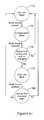
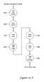
- FIG. 50is a flow diagram showing an illustrative method that may be carried out using the illustrative zone control panel of FIG. 1 ;
- FIG. 51is a flow diagram showing an illustrative method that may be carried out using the illustrative zone control panel of FIG. 1 ;
- FIG. 52is a flow diagram showing an illustrative method that may be carried out using the illustrative zone control panel of FIG. 1 ;
- FIG. 53is a flow diagram showing an illustrative method that may be carried out using the illustrative zone control panel of FIG. 1 ;
- FIG. 54is a flow diagram showing an illustrative method that may be carried out using the illustrative zone control panel of FIG. 1 ;
- FIG. 55is a flow diagram showing an illustrative method that may be carried out using the illustrative zone control panel of FIG. 1 ;
- FIG. 56is a flow diagram showing an illustrative method that may be carried out using the illustrative zone control panel of FIG. 1 ;
- FIG. 57is a flow diagram showing an illustrative method that may be carried out using the illustrative zone control panel of FIG. 1 ;
- FIG. 58shows aspects of a method that may be carried out using the illustrative zone control panel of FIG. 1 ;
- FIG. 59shows aspects of a method that may be carried out using the illustrative zone control panel of FIG. 1 ;
- FIG. 60is a flow diagram showing an illustrative method that may be carried out using the illustrative zone control panel of FIG. 1 ;
- FIGS. 61A-61Dprovide a flow diagram showing an illustrative zone control panel configuration mode that may be carried out using the illustrative zone control panel of FIG. 1 ;
- FIGS. 62A-62Bprovide a flow diagram showing an illustrative zone control panel checkout mode that may be carried out using the illustrative zone control panel of FIG. 1 .
- the present inventionpertains generally to multi-zone HVAC systems, in which two or more thermostats are connected to a zone control panel.
- the two or more thermostatswhich may each be located within a distinct zone of a conditioned space, may provide the zone control panel with calls for heat, cooling, filtration, ventilation, fan, and/or the like.
- the zone control panelmay, in turn, provide appropriate instructions or signals to the appropriate HVAC equipment such as heating equipment, air conditioning equipment, ventilation equipment, humidification and/or dehumidification equipment, and/or the like. If the thermostats placed within different zones make different calls for heating, cooling and the like, the zone control panel may provide appropriate instructions or signals to open or close particular zone dampers, typically within the duct work of the HVAC system.
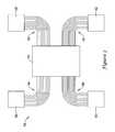
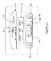
- FIG. 1is a block diagram of an illustrative but non-limiting zone control panel 10 .
- zone control panel 10may include a user interface 12 that may be used to configure, program and/or operate zone control panel 10 or at least certain features thereof.
- Zone control panel 10may include a controller 14 .
- Controller 14may include, for example, a memory and a microprocessor. The memory may be used to store menus, operating instructions and other programming, parameter values and the like, for controlling the zone control panel 10 and the user interface 12 .
- User interface 12may also include a display 16 and a control pad 18 , if desired. While the control pad 18 is shown separate from display 16 in FIG.
- control pad 18 or parts thereofmay be implemented as part of the display 16 , such as when the display 16 is a touch screen type display, if desired.
- display 16may be any suitable display including, for example, a liquid crystal display, an alphanumeric display, a fixed segment display, a dot matrix display, a touch screen display, or any other suitable display, as desired. More generally, display 16 may be any type of display that conveys appropriate information to a user.
- Controller 14may be adapted to, for example, display menus, operating parameters and the like on display 16 and to accept inputs from control pad 18 .
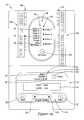
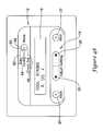
- FIG. 2is a front view of an illustrative embodiment of zone control panel 10 .
- control pad 18may include a back button 20 and a next button 22 that may be used to, for example, select among menu items or perhaps to select between sub-menus within a larger menu, if desired.
- the illustrative control pad 18may also include a first arrow button 24 and a second arrow button 26 . In some cases, first arrow button 24 and/or second arrow button 26 may be used to, for example, select and/or change a parameter or a parameter value.
- control pad 18may include distinct mechanical buttons such as back button 20 , next button 22 , first arrow button 24 and second arrow button 26 . However, and as indicated above, it is contemplated that at least part of control pad 18 could instead be implemented using a touch screen or may be implemented as soft keys, if desired. If control pad 18 is implemented as part of a touch screen, display 16 may also be formed as part of the same touch screen.
- user interface 12may include a mode button 28 .
- a buttonmay include an electro-mechanical button or any other type of button as desired. It will be appreciated that in some cases, zone control panel 10 may be switched between two or more different modes such as a setup or configuration mode, an operational mode and a checkout mode, for example. Mode button 28 may be configured to permit a user to toggle or cycle between these and potentially other operational modes, if desired.
- the mode button 28 , back button 20 , next button 22 , first arrow button 24 and/or second arrow button 26may have unique and constant functions for manipulating the single level menus and/or for setting one or more parameters specified in the menus of the zone control panel 10 . That is, and in some embodiments, these buttons may be dedicated to performing these tasks, and in some cases, may be marked with distinct markings or indicia that indicate to the user the dedicated task. While this is not required in all embodiments, when so provided, this may increase the intuitive nature of the zone control panel user interface.
- user interface 12may also include a mode indicator light set 30 that may provide visual confirmation of the particular mode selected.
- mode light set 30includes an operational mode light 32 , a configuration mode light 34 and a checkout mode light 36 . As mode button 28 is pressed to move between these modes, the appropriate mode light may be illuminated. Any suitable light source may be used, although in some cases, operational mode light 32 , configuration mode light 34 and checkout mode light 36 may each include one or more LEDs.
- Zone control panel 10may include a secondary control panel 38 .
- Secondary control panel 38may, as illustrated, include a bank of HVAC status lights 40 .
- the HVAC status lights 40may be used to, for example, indicate whether the heating equipment is running, and if so, if the first stage, second stage or third stage heating equipment is running.
- HVAC status lights 40may be used to indicate the operational status of the cooling equipment, fan, ventilation equipment, and/or the like.
- HVAC status lights 40may also be used to verify that zone control panel 10 is able to communicate with and/or is properly connected to the appropriate HVAC equipment.
- secondary control panel 38may also, if desired, include a bank of zone lights 42 .
- zone lights 42may be used to indicate which zone dampers are open or closed, whether or not zone control panel 10 is able to communicate with each of the zone dampers within each zone, and/or which zones are currently serving heating, cooling or ventilation demands, for example.
- both HVAC status lights 40 and zone lights 42may be LEDs, although this is not required.
- Secondary control panel 38may also include an emergency heat button 44 that can be used to, for example, put the HVAC equipment into an emergency heating mode.
- the illustrative zone control panel 10may also include a first bank 46 of connection points and a second bank 48 of connection points. In some cases, one or both of first bank 46 and/or second bank 48 of connection points, or portions thereof, may be used for electrically connecting each of the remotely located thermostats to zone control panel 10 . In some cases, one or both of first bank 46 and/or second bank 48 of connection points, or portions thereof, may be used for electrically connecting zone HVAC equipment and zone dampers to zone control panel 10 .
- zone control panel 10may include a first bank 50 of apertures disposed along first bank 46 of connection points and a second bank 52 of apertures disposed along second bank 48 of connection points.
- first bank 50 of apertures and/or second bank 52 of aperturesmay be adapted to provide ventilation.
- first bank 50 of apertures and/or second bank 52 of aperturesmay be absent.
- first bank 50 of apertures and/or second bank 52 of aperturesmay be adapted to accommodate one or more indicator lights.
- indicator lightsif present, may be used to help confirm electrical connections between zone control panel 10 and one or more pieces of HVAC equipment, one or more zone dampers, and/or the like.
- zone control panel 10is shown without any covers, in order to illustrate particular features of zone control panel 10 . It will be recognized, however, that zone control panel 10 may include one or more covers that may fit over part or all of zone control panel 10 in order to protect zone control panel 10 from dust, to prevent inadvertent access to controls underneath the cover(s), or even to provide a more aesthetically pleasing appearance. If included, one or more covers may snap fit onto zone control panel 10 . In some cases, for example, a cover may be configured to hide essentially all of zone control panel 10 , except for secondary control panel 38 .
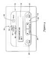
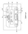
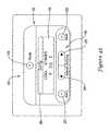
- FIG. 3is a diagrammatic schematic view of an illustrative but non-limiting HVAC control system in accordance with the present invention.
- the illustrative HVAC control system 54includes a first thermostat 56 , a second thermostat 58 , a third thermostat 60 and a fourth thermostat 62 all connected to zone control panel 10 .
- first thermostat 56is connected through a total of eleven wires 64
- second thermostat 58is connected through a total of eleven wires 66
- third thermostat 60is connected through a total of eleven wires 68
- fourth thermostat 62is connected through a total of eleven wires 70 .
- each thermostatmay instead be connected through two, three, four, five, six, seven, eight, nine, ten, or even more than eleven wires, depending on the type of HVAC equipment being controlled and the exact functionality of the thermostats.
- one or more of the thermostatsmay be connected to the zone control panel 10 via a wireless connection.
- zone control panel 10 in general and user interface 12 in particularmay be configured for ease of use.
- Zone control panel 10may be configured, for example, to operate via one or more menus that each includes a number of menu screens.
- zone control panel 10may be configured to permit a user to scroll through a menu, from one menu screen to the next, while staying on a single menu level, without hierarchal sub-menus.
- a single level menumay be considered as including a number of menu screens that may be sequentially viewed, sometimes either in a forwards direction and/or a backwards direction, easily and intuitively.
- a series of menu screensmay be viewed sequentially but one or more menu screens may be skipped if, for example, a particular menu screen is not applicable as a result of an option selection or parameter value set in a previous menu screen.
- a menumay include several menu modes.
- Zone control panel 10may, for example, be configured to permit a user to select and then travel through several menu modes.
- Each menu modemay include a sequential series of menu screens, as referenced above.
- the following Figuresprovide examples of menu screens that demonstrate the easy-to-use and intuitive nature of the illustrative zone control panel 10 .
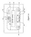
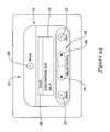
- FIG. 4shows a portion of zone control panel 10 , illustrating a particular operating condition.
- FIG. 4shows user interface 12 , including display 16 .
- Zone control panel 10is illustrated in a DATS (Discharge Air Temperature Sensor) mode. In some instances, this may be considered as the normal run mode, as zone control panel 10 is not in a configuration mode, in which configuration parameters may be set, and is not in a checkout mode, in which connections between zone panel 10 and other equipment may be confirmed.
- DATSCharge Air Temperature Sensor
- controller 14may be configured or programmed to display a current sensor reading for a discharge air temperature sensor of the HVAC system, as well as displaying easy-to-read text confirming (in addition to operational mode light 32 being lit) what mode zone control panel 10 is in, as well as explaining the meaning and/or context of the sensor reading being displayed on display 16 .
- a usermay be able to cause zone control panel 10 to enter a configuration mode by, for example, pressing mode button 28 .
- mode button 28is a dedicated mode select button that has the single function of selecting the mode of the user interface 12 and/or zone control panel 10 .
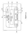
- FIGS. 5 through 22show various menu screens that may be displayed upon user interface 12 when zone control panel 10 is in its configuration mode.
- FIG. 5shows the menu screen that may appear when mode button 28 is pushed once while zone control panel 10 is in its DATS mode.
- operational mode light 32is no longer illuminated while configuration mode light 34 is now illuminated.
- display 16a user is being asked to specify the type of system that zone control panel 10 is connected to.
- controller 14( FIG. 1 ) asks the user to pick between a conventional system and a heat pump system. It is contemplated that additional options may be provided, such as a geothermal system or perhaps an HVAC system that is entirely powered by site-generated electricity such as solar or wind power. In some cases, controller 14 may be programmed to default to a particular setting, and the user may then toggle between the default setting and other setting(s). As illustrated, a conventional system is now selected, but a user may toggle to the heat pump option simply by pressing second arrow button 26 . Once a system type is selected, a user may move to the next menu screen in sequence by pressing next button 22 .
- FIG. 6provides a view of zone control panel 10 displaying the next menu screen.
- controller 14( FIG. 1 ) asks the user to configure the number of cooling stages.
- Display 16provides both a textual description of the parameter to be set as well as the parameter values to choose from, thereby assisting the user in operating zone control panel 10 .
- what is displayed in a particular menu screenmay be dependent upon previous parameter selections. For example, selecting a number of cooling stages may depend, at least in part, on the previous selection of a conventional system type. If another system type had been selected, it should be recognized that controller 14 may instead be requesting a different parameter selection at this point.
- controller 14( FIG. 1 ) permits a user to specify whether there are 0, 1 or 2 cooling stages that may be controlled via zone control panel 10 . In some cases, these options may be different. In some instances, a user may, for example, be asked to choose whether there are 0 or 1 cooling stages only. Perhaps more than 2 cooling stages may be present, and thus controller 14 may permit a user to select between 0, 1, 2, 3, 4 or even more cooling stages. A user may scroll back and forth between the options displayed on display 16 by pressing either the first arrow button 24 and/or the second arrow button 26 . As shown, one cooling stage has been selected. Once the number of cooling stages has been selected, a user may move to the next menu screen in sequence by pressing next button 22 .
- FIG. 7provides a view of zone control panel 10 displaying the next menu screen.
- controller 14( FIG. 1 ) asks the user to configure the number of heating stages.
- Display 16provides both a textual description of the parameter to be set as well as the parameter values to choose from, thereby assisting the user in using zone control panel 10 .
- what is displayed in a particular menu screenmay be dependent upon previous parameter selections. For example, selecting a number of heating stages may depend, at least in part, on the previous selection of a conventional system type. If another system type had been selected, it should be recognized that controller 14 may instead be requesting a different parameter selection at this point.
- controller 14permits a user to specify whether there are 0, 1, 2, or 3 heating stages that may be controlled via zone control panel 10 . In some cases, these options may be different. In some instances, a user may, for example, be asked to choose whether there are 0 or 1 heating stages only. Perhaps more than 3 heating stages may be present, and thus controller 14 may permit a user to select between an appropriate number of heating stages. A user may scroll back and forth between the options displayed on display 16 by pressing either the first arrow button 24 and/or the second arrow button 26 . As shown, one heating stage has been selected. Once the number of heating stages has been set, a user may move to the next menu screen in sequence by pressing next button 22 . Note also, that a user may move to a previous menu screen by pressing the back button 20 , at which time the user may change a previous parameter selection if desired.
- one or more of the menu screensmay enable a user to select a number of zones that the zone control panel 10 should control.
- the zone control panel 10may be capable of controlling four zones, but a particular building may only have three zones.
- the usermay use one or more menu screens to select the number of zones that are actually installed and/or connected in the building.
- the zone control panelmay then control the zones based, at least in part, on the number of selected zones, rather than on the four zone capability of the illustrative zone control panel 10 .
- the controller 14 of the zone control panel 10may uses a control algorithm that accepts as an input the number of zones to actually control. The control algorithm may control the zones differently depending on the number of selected zones.
- FIG. 8provides a view of zone control panel 10 displaying the next menu screen from FIG. 7 .
- controller 14( FIG. 1 ) asks the user to specify how many different zones are to be controlled via zone control panel 10 .
- Display 16provides textual information identifying the parameter to be set as well as options for its numerical value. In some cases, this may make zone control panel 10 easier and more intuitive to use.
- controller 14may display a numerical value that can be incremented by pressing the second arrow button 26 and/or decremented by pressing the first arrow button 24 , rather than simply presenting predetermined options that a user may scroll between.
- display 16may provide visual representations of the button or buttons that may be used to set or change the displayed parameter.
- display 16shows a left arrow on the left side of the displayed parameter value (corresponding to left arrow button 24 ) and a right arrow on the right side of the displayed parameter value (corresponding to right arrow button 26 ).
- the left arrow on the left side of the display 16may be similar to the indicia or markings on the left arrow button 24
- the right arrow on the right side of the display 16may be similar to the indicia or markings on the right arrow button 26 .
- a usermay be better informed as to how to change the value of the displayed parameter.
- buttonsmay be considered as helping the user to understand operation of zone control panel 10 and thus may help make zone control panel 10 more intuitive and easy-to-use.
- the userhas specified that four zones are present. Once this has been set, a user may move to the next menu screen in sequence by pressing next button 22 .
- FIG. 9provides a view of zone control panel 10 displaying the next menu screen from FIG. 8 .
- controller 14( FIG. 1 ) asks the user whether he or she wishes to travel through the advanced configuration menu screens.
- Display 16provides both a textual description of the question as well as the available answers to toggle between in order to assist the user.
- a usermay toggle back and forth between NO and YES options displayed on display 16 by pressing either the first arrow button 24 and/or the second arrow button 26 .
- a userhas selected NO. Pressing the next button 22 will cause controller 14 to advance to a menu screen represented in FIG. 19 .
- controller 10will display the first of one or more advanced configuration menu screens as shown in FIG. 11 .
- controller 14( FIG. 1 ) asks the user to specify whether heat fan control should be controlled by the HVAC equipment itself or if zone control panel 10 should be configured to override the HVAC equipment.
- Display 16provides both a textual description of the question as well as the available answers to toggle between in order to make zone control panel 10 easier to use.
- a usermay toggle between the options displayed on display 16 by pressing either the first arrow button 24 and/or the second arrow button 26 .
- a userhas specified that the HVAC equipment should control the heat fan. Once this has been set, a user may move to the next menu screen in sequence by pressing next button 22 .
- FIG. 12provides a view of zone control panel 10 displaying the next menu screen from FIG. 11 .
- controller 14FIG. 1
- Display 16provides both a textual description of the parameter to be set as well as the parameter values to choose from, thereby providing ease of use.
- a usermay toggle back and forth between options displayed on display 16 by pressing either the first arrow button 24 and/or the second arrow button 26 .
- a userhas selected a purge time of 2 minutes. Once this has been set, a user may move to the next menu screen in sequence by pressing next button 22 .
- FIG. 13provides a view of zone control panel 10 displaying the next menu screen.
- controller 14FIG. 1
- Display 16improves ease of use by providing both a textual description of the parameter to be set as well as the parameter values to choose from.
- a usermay toggle back and forth between options displayed on display 16 by pressing either the first arrow button 24 and/or the second arrow button 26 .
- a userhas specified that the HVAC equipment provide fan control during purge time. Once this has been set, a user may move to the next menu screen in sequence by pressing next button 22 .
- FIG. 14provides a view of zone control panel 10 displaying the next menu screen.
- controller 14FIG. 1
- Display 16provides both a textual description of the parameter to be set as well as the parameter values to choose from, thereby making zone control panel 10 easier to use.
- a usermay toggle back and forth between options displayed on display 16 by pressing either the first arrow button 24 and/or the second arrow button 26 .
- a userhas specified that the dampers remain unchanged during purge time. Once this has been set, a user may move to the next menu screen in sequence by pressing next button 22 .
- FIG. 15provides a view of zone control panel 10 displaying the next menu screen.
- controller 14FIG. 1
- Display 16provides both a textual description of the parameter to be set as well as the parameter values to choose from in order to assist a user.
- a usermay toggle back and forth between options displayed on display 16 by pressing either the first arrow button 24 and/or the second arrow button 26 .
- a userhas specified a twenty minute changeover delay. Once this has been set, a user may move to the next menu screen in sequence by pressing next button 22 .
- FIG. 16provides a view of zone control panel 10 displaying the next menu screen.
- controller 14FIG. 1
- Display 16provides both a textual description of the parameter to be set as well as the parameter values to choose from in order to make zone control panel 10 easier to use.
- a usermay toggle back and forth between options displayed on display 16 by pressing either the first arrow button 24 and/or the second arrow button 26 .
- a userhas specified that there is a discharge temperature sensor. Once this has been set, a user may move to the next menu screen in sequence by pressing next button 22 .
- FIG. 17provides a view of zone control panel 10 displaying the next menu screen.
- controller 14( FIG. 1 ) asks the user to set a high limit lockout value for the discharge air temperature.
- Display 16improves usability by providing both a textual description of the parameter to be set as well as the parameter values to choose from.
- controller 14may display a numerical value that can be incremented by pressing the second arrow button 26 and/or decremented by pressing the first arrow button 24 , rather than simply presenting predetermined options that a user may toggle between
- display 16may provide visual representations of the button or buttons that may be used to set or change the displayed parameter.
- a userhas set a high limit lockout temperature of 160 degrees Fahrenheit. Once this has been set, a user may move to the next menu screen in sequence by pressing next button 22 .
- FIG. 18provides a view of zone control panel 10 displaying the next menu screen.
- controller 14( FIG. 1 ) asks the user to set a low limit lockout value for the discharge air temperature.
- Display 16provides both a textual description of the parameter to be set as well as the parameter values to choose from to improve usability.
- controller 14may display a numerical value that can be incremented by pressing the second arrow button 26 and/or decremented by pressing the first arrow button 24 , rather than simply presenting predetermined options that a user may toggle between.
- display 16may also provide visual representations of the button or buttons that may be used to set or change the displayed parameter.
- a userhas set a low limit lockout temperature of 40 degrees Fahrenheit. Once this has been set, a user may move to the next menu screen in sequence by pressing next button 22 .
- FIG. 19provides a view of zone control panel 10 displaying the next menu screen.
- FIG. 19is the next menu screen that will be displayed. Or, if the user passes through the advanced configuration menu screens and, in leaving FIG. 18 , presses next button 22 , FIG. 19 may be the next menu screen to be displayed.
- controller 14( FIG. 1 ) asks the user if he or she wishes to save any changes that may have been made within the configuration mode.
- Display 16provides both a textual description of the question being asked as well as the possible answers to choose from, thereby assisting a user.
- a usermay toggle back and forth between options displayed on display 16 by pressing either the first arrow button 24 and/or the second arrow button 26 . In some instances, a user may decide to discard any changes made if, for example, they did not intend to make any changes, or if they are not certain if they made the appropriate changes.
- a userhas elected to discard any changes that may have been intentionally or even unintentionally made within the configuration mode.
- Pressing the next button 22causes the next menu screen to be displayed, as shown in FIG. 20 .
- display 16indicates that zone control panel 10 is exiting the configuration mode.
- zone control panel 10In the case where a user wants to save the changes made while zone control panel 10 was in the configuration mode. As shown in FIG. 21 , a user may toggle between options displayed on display 16 , and thereby select YES, by pressing either the first arrow button 24 and/or the second arrow button 26 . Once this has been set, a user may move to the next menu screen in sequence by pressing next button 22 . As shown in FIG. 22 , controller 14 ( FIG. 1 ) may cause display 16 to provide confirmation that the changes are, in fact, being saved.
- a userhas moved sequentially from menu screen to menu screen, i.e., from FIG. 4 to FIG. 5 , from FIG. 5 to FIG. 6 , and so on. It should be recognized that a user may also move sequentially backwards through the menu. For example, a user could be at the menu screen depicted in FIG. 8 , for example, and return to the menu screen depicted in FIG. 7 simply by pressing the back button 20 . In some instances, a user may move forwards and backwards as desired.
- a usermay scroll through one or more menu screens without making any changes to whatever parameter or setting is shown in a particular menu screen.
- some menu screensmay provide a default setting for a particular parameter. If the default setting is appropriate for a particular situation, a user may scroll through that particular menu screen using the next button 22 and/or the back button 20 , as appropriate, without making any selections or changing any parameter values.
- the controller 14may track whether any changes were indeed made, and if not, the menu screen shown in FIG. 19 may be skipped, and instead the menu screen shown in FIG. 20 may be displayed.
- the controllermay exit the configuration mode.
- the controller 14may track whether any changes were made by the user while in the configuration mode, and if so, the menu screen shown in FIG. 19 may displayed in order to query the user as to whether the changes should be saved. If no changes were made, the controller 14 may skip to the menu screen shown in FIG. 20 .
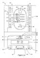
- FIGS. 23 through 43show various illustrative menu screens that may be displayed upon user interface 12 when zone control panel 10 is in its checkout mode.
- FIG. 23shows the menu screen that may appear when mode button 28 is pushed twice from a point in time while zone control panel 10 is in its DATS mode.
- checkout mode light 36is now illuminated while both operational mode light 32 and configuration mode light 34 are both off.
- zone control panel 10may be connected to one or more temperature sensors.
- controller 10FIG. 1
- controller 10FIG. 1
- FIG. 24demonstrates that a discharge temperature sensor is connected to zone control panel 10 and appears to be functioning correctly. A user may move from the menu screen depicted in FIG. 23 to the menu screen depicted in FIG. 24 simply by pressing the next button 22 .
- the checkout modepermits a user, technician or other individual to make sure that the zone control panel 10 is correctly connected to any and/or all HVAC equipment that zone control panel 10 is expected to control, as well as to make sure that the HVAC equipment is functioning correctly.
- zone control panel 10is configured to permit these checks to be made easily and intuitively, without requiring a complicated, hard-to-use, hierarchal menu.
- the menu screen depicted in FIG. 25may, for example, be reached from the menu screen depicted in FIG. 24 by pushing the next button 22 . It will be recognized that at least some of the equipment options tested in this series of menu screens may be dependent on how choices were previously made in the configuration mode, if any changes or choices were made. For example, with respect to testing heat stages, it will be remembered that in the menu screen shown in FIG. 7 , a user selected a single heat stage. Consequently, only one heat stage is tested in the illustrative checkout mode. If the user had previously selected two heat stages, both could now be tested.
- FIG. 25provides a view of zone control panel 10 displaying a menu screen in which controller 14 ( FIG. 1 ) permits a user to test the heating equipment.
- Display 16provides an indication of what HVAC equipment is to be tested, as well as providing options that can be toggled between using the first arrow button 24 and/or the second arrow button 26 . In this case, a user can toggle between not energizing the heat, and energizing first stage heat. As shown in FIG. 25 , no heat is being energized.
- heat 1 light 72is not lit. However, if a user decides to energize the first heat stage, they can so do by toggling to the desired selection, as seen in FIG. 26 . In FIG. 26 , it can be seen that the heat 1 light 72 has now been lit. In some instances, the heat 1 light 72 may be red, but this is not required. It should be noted that in the illustrated example, and as seen in FIGS. 25 through 30 , all of the zone dampers are open as indicated by the zone lights 42 all being lit. In some cases, these lights may be green, but this is not required. Other colors may also be used.
- a dark black fill patternindicates a red color
- a gray fill patternindicates a green color
- FIG. 27provides a view of zone control panel 10 displaying a menu screen in which controller 14 ( FIG. 1 ) permits a user to test the cooling equipment.
- controller 14FIG. 1
- FIG. 27provides a view of zone control panel 10 displaying a menu screen in which controller 14 ( FIG. 1 ) permits a user to test the cooling equipment.
- controller 14FIG. 1
- FIG. 27provides a view of zone control panel 10 displaying a menu screen in which controller 14 ( FIG. 1 ) permits a user to test the cooling equipment.
- controller 14FIG. 1
- Display 16provides an indication of what HVAC equipment is to be tested, as well as providing options that can be toggled between using the first arrow button 24 and/or the second arrow button 26 . In this case, a user can toggle between not energizing the cooling equipment, and energizing first stage cooling. As shown in FIG. 27 , no equipment is being tested.
- cool 1 light 74is not lit. However, if a user decides to test the first cooling stage, they can so do by toggling to the desired selection, as seen in FIG. 28 . In FIG. 28 , it can be seen that the cool 1 light 74 has now been lit. In some instances, a fan light 76 may also be lit when the cooling equipment is operating. In some cases, cool 1 light 74 and/or fan light 76 may be green, but this is not required. Once the cooling equipment has been satisfactorily tested, a user may scroll to the menu screen shown in FIG. 29 by pressing the next button 22 .
- FIG. 29provides a view of zone control panel 10 displaying a menu screen in which controller 14 ( FIG. 1 ) permits a user to test the HVAC fan.
- Display 16provides an indication of what HVAC equipment is to be tested, as well as providing options that can be toggled between using the first arrow button 24 and/or the second arrow button 26 . In this case, a user can toggle between not energizing the fan, and energizing the fan. As shown in FIG. 29 , no equipment is being energized.
- FIGS. 31 through 38illustrate menu screens in which a user is permitted to selectively open and/or close the dampers relating to each of the zones that are connected to zone control panel 10 , thereby testing the connections as well as the dampers themselves.
- the fanmay be energized during the damper test, as evidenced by fan light 76 .
- secondary control panel 38is configured to provide information pertaining to a total of four zones, but it will be recognized that in some instances, secondary control panel 38 may be configured to accommodate a greater number of zones if desired.
- the configuration modesee FIG. 8
- the userspecified that there were a total of four zones connected.
- each zone damperdefaults to open, but this is not required.
- FIG. 31provides a view of zone control panel 10 displaying a menu screen in which controller 14 ( FIG. 1 ) permits a user to test the zone one damper.
- Display 16provides an indication of what HVAC equipment is to be tested, as well as providing options that can be toggled between using the first arrow button 24 and/or the second arrow button 26 . In this case, a user can toggle between opening the damper and closing the damper. As shown in FIG. 31 , the damper is left open.
- zone 1 light 78is lit green indicating that the damper is open. However, if a user decides to close the first zone damper, they can so do by toggling to the desired selection, as seen in FIG. 32 . In FIG. 32 , it can be seen that the zone 1 light 78 has now changed colors to red. In some instances, a green light may indicate an open damper while a red light may indicate a closed damper, but this is not required.
- FIG. 33provides a view of zone control panel 10 displaying a menu screen in which controller 14 ( FIG. 1 ) permits a user to test the zone two damper.
- Display 16provides an indication of what HVAC equipment is to be tested, as well as providing options that can be toggled between using the first arrow button 24 and/or the second arrow button 26 . In this case, a user can toggle between opening the damper and closing the damper. As shown in FIG. 33 , the damper is left open.
- zone 2 light 80is lit green.
- a userdecides to close the second zone damper, they can so do by toggling to the desired selection, as seen in FIG. 34 .
- the zone 2 light 80has now changed colors or red, indicating that the zone two damper is closed.
- a green lightmay indicate an open damper while a red light may indicate a closed damper, but this is not required.
- FIG. 35provides a view of zone control panel 10 displaying a menu screen in which controller 14 ( FIG. 1 ) permits a user to test the zone three damper.
- Display 16provides an indication of what HVAC equipment is to be tested, as well as providing options that can be toggled between using the first arrow button 24 and/or the second arrow button 26 . In this case, a user can toggle between opening the damper and closing the damper. As shown in FIG. 35 , the damper is left open.
- zone 3 light 82is lit green.
- a userdecides to close the third zone damper, they can so do by toggling to the desired selection, as seen in FIG. 36 .
- the zone 3 light 82has now changed colors to red.
- a green lightmay indicate an open damper while a red light may indicate a closed damper, but this is not required.
- FIG. 37provides a view of zone control panel 10 displaying a menu screen in which controller 14 ( FIG. 1 ) permits a user to test the zone four damper.
- Display 16provides an indication of what HVAC equipment is to be tested, as well as providing options that can be toggled between using the first arrow button 24 and/or the second arrow button 26 . In this case, a user can toggle between opening the damper and closing the damper. As shown in FIG. 37 , the damper is left open.
- zone 4 light 84is lit green.
- a userdecides to close the fourth zone damper, they can so do by toggling to the desired selection, as seen in FIG. 38 .
- the zone 4 light 84has now changed colors to red.
- a green lightmay indicate an open damper while a red light may indicate a closed damper, but this is not required.
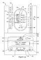
- FIGS. 39 through 42illustrate menu screens in which a user is permitted to check connections between zone control panel 10 and the thermostats that are connected to zone control panel 10 .
- each of the thermostatssuch as first thermostat 56 , second thermostat 58 , third thermostat 60 and fourth thermostat 62 (see FIG. 3 ) may be individually set to a particular operating condition.
- Zone control panel 10is configured to permit an individual to scroll through a series of menu screens to confirm that zone control panel 10 is receiving appropriate signals from each of the thermostats and therefore a user is able to easily confirm that each of the thermostats are correctly connected (e.g. wired) to zone control panel 10 and that each of the thermostats are functioning correctly.
- controller 14( FIG. 1 ) is providing a menu screen in which display 16 provides information relating to the signals being received from the thermostat for zone one. It can be seen that the thermostat in zone one has been set to call for the fan to operate, as indicated by the G pin being energized. If the zone control panel indicates that a different pin is energized, such as a W1 pin, then the user may need to diagnose a wiring error between the thermostat and the zone control panel. Pushing the next button 22 may result in the display of the menu screen shown in FIG. 40 .
- controller 14( FIG. 1 ) is providing a menu screen in which display 16 provides information relating to the signals being received from the thermostat in zone two. It can be seen that the thermostat in zone two has been set to call for first stage heating, as indicated by the W1 pin being energized. Again, if the zone control panel indicates that a different pin is energized, then the user may need to diagnose a wiring error between the thermostat and the zone control panel. Pushing the next button 22 will permit a user to scroll to the menu screen shown in FIG. 41 .
- controller 14( FIG. 1 ) is providing a menu screen in which display 16 provides information relating to the signals being received from the thermostat in zone three. It can be seen that the thermostat in zone three has been set to call for first and second stage heating, as indicated by the W1 pin and the W2 pin being energized. Like above, if the zone control panel indicates that a different pin or set of pins is energized, then the user may need to diagnose a wiring error between the thermostat and the zone control panel. Pushing the next button 22 will permit a user to scroll to the menu screen shown in FIG. 42 .
- controller 14( FIG. 1 ) is providing a menu screen in which display 16 provides information relating to the signals being received from the thermostat in zone four. It can be seen that the thermostat in zone four has been set to call for first stage cooling, and that the fan is operational, as indicated by the Y1 pin and the G pin being energized. If the zone control panel indicates that a different pin or set of pins is energized, then the user may need to diagnose a wiring error between the thermostat and the zone control panel. Pushing the next button 22 will permit a user to scroll to the menu screen shown in FIG. 43 .
- controller 14( FIG. 1 ) is providing a menu screen in which display 16 provides a user with information regarding how to exit the checkout mode.
- a usercould decide to scroll backwards through one or more menu screens by pushing the back button 20 an appropriate number of times if, for example, he/she wanted to recheck and/or change one or more items within the checkout mode.
- the usermay do so by pressing the next button 22 .
- a userhas moved sequentially from menu screen to menu screen, i.e., from FIG. 30 to FIG. 31 , from FIG. 31 to FIG. 32 , and so on. It will be recognized that a user may also move sequentially backwards through the menu. For example, a user could be at the menu screen depicted in FIG. 35 , for example, and return to the menu screen depicted in FIG. 34 simply by pressing the back button 20 . In some instances, a user may move forwards and backwards as desired.
- a usermay scroll through one or more menu screens within the checkout mode without selecting/changing any equipment, zone damper and/or thermostat tests, if desired, by using the next button 22 and/or the back button 20 , as appropriate. For example, perhaps all equipment, zone dampers and thermostats have already been tested, and an error was found. Once the error has been corrected, a user may wish to test only the affected equipment, zone damper or thermostat without taking the time to retest everything else.
- a usermay change between one or more modes programmed or otherwise present within zone control panel 10 via mode selector button 28 and may receive visible confirmation of the selected mode via mode light set 30 , which may, if desired, include one or more of operational mode light 32 , configuration mode light 34 and checkout mode light 36 .
- mode light set 30may, if desired, include one or more of operational mode light 32 , configuration mode light 34 and checkout mode light 36 .
- FIGS. 44 through 49provide illustrative alternatives to one or both of mode selector button 28 and mode indicator light set 30 .
- zone control panel 10may include mode selector button 28 but not include mode indicator light set 30 .
- FIG. 44shows a portion of zone control panel 10 in which display 16 includes an additional display section 86 .
- controller 14may generate an alphanumeric or iconic image within display section 86 that informs a user as to what mode zone control panel 10 is in.
- additional display section 86may be adjacent to display 16 .
- additional display section 86may be an integral part of display 16 .
- the additional display section 86may be considered a mode indicator.
- display section 86could display an image of a hard hat to denote the configuration mode, or perhaps an image of a checkmark to denote the checkout mode. Any informative icon or clip art could be used, as desired.
- zone control panel 10is in the DATS, or operational, mode.
- controller 14( FIG. 1 ) indicates the mode by displaying “DATS”, or some other indicator, within display section 86 while in FIG. 4 , controller 14 provides similar information by illuminating operational mode light 32 .
- FIG. 45shows a portion of zone control panel 10 in which additional display section 86 provides an indication that zone control panel 10 is in the configuration mode.
- controller 14( FIG. 1 ) indicates the mode by displaying “Config”, or some other indicator, within display section 86 . This can be compared to FIG. 6 , in which controller 14 provides similar information by illuminating configuration mode light 34 .
- FIG. 46shows a portion of zone control panel 10 in which additional display section 86 provides an indication that zone control panel 10 is in the checkout mode.
- controller 14( FIG. 1 ) indicates the mode by displaying “Check Out”, or some other indicator, within display section 86 . This can be compared to FIG. 23 , in which controller 14 provides similar information by illuminating checkout mode light 36 .
- FIGS. 47 through 49show a portion of zone control panel 10 including another illustrative mode selector and mode indicator.
- user interface 12may include a mode selector 88 that may be a rotary dial or switch.
- a rotary dial or switchmay include an electro-mechanical rotary dial or switch, or any other type of rotary dial or switch as desired.
- mode selector 88may include one or more detents (not shown) that may assist a user in rotating mode selector 88 an appropriate amount.
- User interface 12may also include a mode indicator including a pointer 90 that may be a marking on mode selector 88 , an indentation within mode selector 88 , or the like.
- Indiciasuch as a DATS mode indicia 92 , a configuration mode indicia 94 and a checkout mode indicia 96 may be disposed proximate mode selector 88 such that pointer 90 in combination with the aforementioned indicia provide an indication of the mode that has been selected.
- zone control panel 10is in the DATS, or operational, mode.
- Mode selector 88has been rotated such that pointer 90 points to (or aligns with) DATS mode indicia 92 , thereby showing what mode has been selected. This can be compared with the menu screen shown in FIG. 4 , in which controller 14 provides similar information by illuminating operational mode light 32 .
- zone control panel 10is in the configuration mode.
- Mode selector 88has been rotated such that pointer 90 points to (or aligns with) configuration mode indicia 94 , thereby showing what mode has been selected. This can be compared to FIG. 6 , in which controller 14 provides similar information by illuminating configuration mode light 34 .
- zone control panel 10is in the checkout mode.
- Mode selector 88has been rotated such that pointer 90 points to (or aligns with) checkout mode indicia 96 , thereby showing what mode has been selected. This can be compared to FIG. 23 , in which controller 14 provides similar information by illuminating checkout mode light 36 .
- mode selector 88has been illustrated as a rotary dial or switch. In some instances, it is contemplated that mode selector 88 could instead be a slider switch.
- a slider switchcould be mounted in an orientation such that its motion is vertical.
- a slider switchcould have an upper position corresponding to DATS mode indicia 92 , an intermediate position corresponding to configuration mode indicia 94 and a lower position corresponding to checkout mode indicia 96 . It is also contemplated that such a slider switch could be mounted in a horizontal or any other orientation, as desired.
- zone control panel 10may have more or less than three distinct modes.
- zone control panel 10may have a history mode, which would permit a user to review operational data going back any desired period of time, such as a day, a week, a month or the like.
- zone control panel 10may be configured to include a future mode, which may permit an additional mode to be programmed into zone control panel 10 at some future date. Any number of potential modes are contemplated, which may be dependent on the desired application and/or expected use of the zone control panel 10 .
- FIG. 50shows a method that may be carried out using illustrative zone control panel 10 .
- a first modemay be selected using a mode selector such as mode selector 28 ( FIG. 2 ) or mode selector 88 ( FIGS. 47-49 ), for example.
- Controlpasses to block 100 , where a visual indication of the selected mode is provided.
- controller 14FIG. 1
- a visual indication of the selected modemay be provided via mode selector 88 in combination with pointer 90 and indicia 92 , 94 and 96 ( FIGS. 47-49 ).
- Controlthen passes to block 102 , where a selected menu that corresponds to the selected mode is displayed.
- controller 14may display one or more menu screens that correspond to the selected mode on display 16 .
- FIG. 51shows a method that may be carried out using illustrative zone control panel 10 .
- a first modemay be selected using a mode selector such as those discussed above with respect to FIG. 50 .
- Controlpasses to block 100 , where a visual indication of the selected mode is provided as discussed above.
- a selected menuthat corresponds to the selected mode may be displayed.
- a second modemay be selected using a mode selector.
- Controlpasses to block 108 , where a visual indication of the selected mode is provided as discussed above.
- a selected menu that corresponds to the selected modemay be displayed, as discussed above.
- FIG. 52is a flow diagram that outlines how a user may, if desired, navigate between different modes using zone control panel 10 .
- zone control panel 10may be considered as being in a normal or operational mode.
- Controlpasses to block 114 as a mode button (such as mode selector 28 or mode selector 88 ) is pressed once.
- zone control panel 10is in a configuration mode as previously discussed. If the mode button is pressed again, control passes to block 116 , where controller 14 determines if the user is still at the first configuration step and if no changes have been made. If not, control returns to block 112 . If the answer is yes, control passes to block 118 where zone control panel 10 enters a checkout mode. If the mode button is pressed again, control passes to block 120 where controller 14 ( FIG. 1 ) determines if the user is still at an initial or first checkout step. In either event, pressing the mode button while in the checkout mode causes control to return to block 112 .
- controller 14FIG. 1
- FIG. 53is a flow diagram that illustrates some navigational aspects of, for example, the configuration mode.
- an eventhas occurred that may cause zone control panel 10 to exit the configuration mode. Examples of such events include declining entry into an advanced configuration mode, pressing the next button 22 ( FIG. 2 ) at a last configuration mode menu screen, pressing the mode button anytime after entering the configuration mode, and/or an inactivity timeout.
- a determinationis made as to whether any parameters or parameter values have been changed while zone control panel 10 was in the configuration mode. If no changes were made, zone control panel 10 exits the configuration mode.
- a querymay, for example, be provided on display 16 ( FIG. 1 ), such as shown in FIG. 21 .
- the changes are not to be savedthe changes are discarded and zone control panel 10 exits the configuration mode.
- the changesare saved and then zone control panel 10 exits the configuration mode.
- the display 16may show a confirmation message to the user that the changes are being saved, as shown in, for example, FIG. 22 .
- FIG. 54shows an illustrative method that may be carried out using illustrative zone control panel 10 .
- a menu select buttonmay be pushed to select a menu mode.
- Controlpasses to block 132 , where controller 14 ( FIG. 1 ) displays a menu that corresponds to the menu mode that was selected at block 130 .
- the menumay be displayed on display 16 ( FIG. 1 ), but this is not required.
- push buttonsmay be pushed to move along a single menu level menu structure. In some cases, at optional block 136 , changes may be made to programmable parameters that are identified by the menu structure.
- Controlpasses to block 138 , where pressing the mode select button causes zone control panel 10 to exit the menu mode.
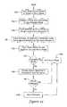
- FIG. 55shows another illustrative method that may be carried out using illustrative zone control panel 10 .
- a menu select buttonmay be pushed to select a menu mode.
- the menu select buttonmay correspond to the mode button 28 discussed above, and the menu mode may correspond a corresponding mode of the zone control panel 10 .
- Controlthen passes to block 132 , where controller 14 ( FIG. 1 ) displays a menu that corresponds to the menu mode that was selected at block 130 .
- push buttonsmay be pushed to move along a single menu level menu structure. In some cases, at optional block 136 , changes may be made to programmable parameters that are identified by the menu structure. Control passes to block 138 , where pressing the mode select button causes zone control panel 10 to exit the selected menu mode.
- control passes to decision block 140where controller 14 ( FIG. 1 ) determines whether any changes were made. If no changes were made, control passes to block 144 and the selected menu mode is exited. However, if changes were made, control passes to block 142 , where zone control panel 10 displays a query asking whether or not the changes should be saved. At decision block 146 , controller 14 examines the answer. If the changes are not to be saved, control passes to block 144 and the selected menu mode is exited. If the changes are to be saved, control passes to block 148 and the changes are saved. In some cases, the menu mode may be exited after the changes are saved.
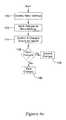
- FIG. 56shows another illustrative method that may be carried out using illustrative zone control panel 10 .
- a number of connected zonesmay be inputted.
- zone control panel 10may be configured to accommodate a particular maximum number of zones.
- zone control panel 10may be connected to a number of zones that is less than the maximum number of zones.
- controller 14FIG. 1
- controller 14FIG. 1
- controller 14FIG. 1
- controller 14FIG. 1
- controller 14may display a query on display 16 ( FIG. 1 ), and a user may input an answer using control pad 18 ( FIG. 1 ), as previously discussed.
- Controlthen passes to block 152 , where zone control panel 10 controls the number of connected zones.
- the zone control panelmay have a controller that uses a control algorithm that accepts as an input the number of zones to actually control, as previously discussed. The control algorithm may control the zones differently depending on the number of selected zones.
- FIG. 57shows yet another illustrative method that may be carried out using illustrative zone control panel 10 .
- a number of connected zonesmay be inputted, if desired. In some cases, the number of connected zones may be less than the maximum number of zones.
- Controlpasses to block 154 , where a thermostat type may be inputted for each of the connected zones.
- controller 14FIG. 1
- controller 14may display a query on display 16 ( FIG. 1 ), and a user may input an answer using control pad 18 ( FIG. 1 ), as previously discussed.
- a thermostat controlling a particular zonemay be set up as a conventional thermostat, a heat pump thermostat, and/or any other suitable thermostat type.
- Controlpasses to block 156 , where zone control panel 10 operates in accordance with the number of connected zones (as inputted at block 150 ) as well as the types of thermostats (as inputted at block 154 ). In some cases, different thermostat types will make a heating call or a cooling call, for example, by energizing different pins or pin combinations.
- the pins energized by a conventional thermostatmay be different from the pins energized by a heat pump thermostat. Informing zone control panel 10 of the number and types of zones and/or the types of thermostats connected to zone control panel 10 , controller 14 ( FIG. 1 ) may be better suited to operating the HVAC system to which it may be connected.
- FIG. 58shows some aspects of the methods shown in FIGS. 56 and 57 .
- the number of installed and/or connected zonesmay be utilized in various control algorithms used by zone control panel 10 . For example, and as shown, if only one zone is installed, zone control panel 10 may use that number in operational control algorithms. Similarly, if there are two, three or four zones installed and/or connected, that number will be used in the operational control algorithms.
- the operational control algorithmsmay control the zones differently depending on the number of selected zones.
- zone 1 light 78may be a first color (e.g. green) to signify that the damper is open and a second color (e.g. red) to signify that the damper is closed.
- Zone 2 light 80 , zone 3 light 82 and zone 4 light 84may remain off, or not illuminated.
- zone 1 light 78 and zone 2 light 80may be illuminated if two zones are connected while zone 3 light 82 and zone 4 light 84 remain off. If three zones are present, zone 1 light 78 , zone 2 light 80 and zone 3 light 82 may be illuminated while zone 4 light 84 may remain off. If four zones are installed and/or connected, of course all four zone lights 78 , 80 , 82 and 84 may be illuminated.
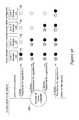
- FIG. 59shows some aspects of the methods shown in FIGS. 56 and 57 .
- a thermostat typehas been specified for a particular zone. Depending on what type of thermostat has been specified, it will be recognized that zone control panel 10 may receive different inputs for a particular desired effect.
- the specified thermostat typeis a conventional thermostat
- its active inputsmay include energizing the Y1 pin for a cooling call and the W1 pin for a heating call. If there are two cooling stages and/or two heating stages, block 162 may include energizing the Y1 and the Y2 pins for second stage cooling and/or energizing the W1 and the W2 pins for second stage heating, for example.
- zone control panel 10may be configured to accommodate other or future thermostat types, if desired.
- FIG. 60shows an illustrative method that may be carried out using illustrative zone control panel 10 .
- menu settingsmay be displayed. This may include displaying a menu screen or a sequence of menu screens on a display such as display 16 ( FIG. 1 ).
- changesmay be inputted to the menu settings. In some instances, this may include a user inputting changes using user interface 12 , as discussed with respect to previous Figures.
- Controlpasses to block 174 , where controller 14 ( FIG. 1 ) asks if changes should be saved.
- controlmay pass to optional decision block 176 , where zone control panel 10 may determine the answer to the question asked at block 174 . If the answer is no, control may pass to optional block 178 where the changes are discarded. Otherwise, control may pass to optional block 180 , where the changes are saved.
- FIGS. 61A-61Dshow an illustrative sequence of menu screens that may be scrolled through while zone control panel 10 is in a configuration mode. It will be recognized that while the menu screens are in a particular sequence, not all menu screens may be accessed and displayed, depending at least in part on how previous settings were or were not changed. For example, if a particular menu screen requests information regarding HVAC system type, and a user answers conventional, any menu screens pertaining to heat pump settings may be skipped. It should also be recognized that these are only illustrative menu screens, and that other menu screens may be employed, and in a different order, if desired.
- menu screensmay be scrolled through either forwards or backwards using the back button 20 ( FIG. 2 ) and/or the next button 22 ( FIG. 2 ), as desired.
- the menu screensmay prompt the user to scroll backwards and correct their answer to the system type question.
- menu screen 182pertains to system type, i.e., conventional, heat pump, or perhaps other system types as well.
- menu screen 184 and menu screen 186deal with fuel types and number of compressors, respectively, and may be skipped if the system type is conventional.
- Menu screen 188 and menu screen 190pertain to the number of cooling stages and the number of heating stages, respectively.
- Menu screen 192pertains to the number of duel fuel stages and menu screen 194 deals with the number of auxiliary stages, respectively. It will be recognized that menu screen 192 , for example, may be skipped if a user answers no to the duel fuel enabled question posed in menu screen 184 .
- Menu screen 196pertains to specifying a number of zones that are to be controlled by the zone control panel 10 .
- Menu screen 198 and menu screen 200pertain to stage 2 control and stage 3 control, respectively.
- Menu screen 202permits a user to enter to skip an advanced settings portion of the menu, if desired. A number of the following menu screens may be skipped if a user does not enter the advanced settings portion.
- Menu screens 204 , 206 , 208 , 210 and 212pertain to heat fan, stage 2 timer, stage 3 timer, purge timer and purge fan settings, respectively.
- Menu screens 214 , 216 , 218 , 220 , 222 , 224 , 226 and 228pertain to purge damper, auto change delay, DATS enablement, DATS high limit, DATS low limit, MStg DATS Inhibit, Duel fuel changeover and ODTemp enablement, respectively.
- Menu screens 230 , 232 and 234pertain to MStg OD lockout, Duel fuel OD Trip, and MStg OD trip, respectively.
- Menu screen 236permits a user to enter and/or display information pertaining to the thermostat type connected to zone one.
- menu screens 238 , 240 and 242permit a user to enter and/or display information pertaining to the thermostat types connected to zones two, three, and four, respectively.
- menu screen 242may be the final menu screen in sequence within the configuration mode.
- FIGS. 62A-62Bshow an illustrative sequence of menu screens that may be scrolled through while zone control panel 10 is in a checkout mode. It will be recognized that while the menu screens are in a particular sequence, not all menu screens may be accessed and displayed, depending at least in part on how previous settings were or were not changed in the configuration mode. Further, it should be recognized that the menu screens may be scrolled through either forwards or backwards using the back button 20 ( FIG. 2 ) and/or the next button 22 ( FIG. 2 ), as desired. It should also be recognized that these are only illustrative menu screens, and that other menu screens may be employed, and in a different order, if desired.
- Menu screen 244pertains to testing an outdoor temperature sensor, if one is present, while menu screen 246 pertains to testing the discharge air temperature sensor.
- the heating equipmentmay be tested at menu screen 248 . It will be recognized that if only a single heating stage was specified in the configuration mode, only a single heating stage may be tested in menu screen 248 . If additional heating stages were specified, they may be tested here as well.
- Emergency heatif present, may be tested in menu screen 250 . If no emergency heat capability is present, menu screen 250 may be skipped. Similarly, any and all installed and specified cooling stages may be tested in menu screen 252 while the fan may be tested in menu screen 254 .
- the zone one, zone two, zone three and zone four dampersmay be tested in menu screens 256 , 258 , 260 and 262 , respectively, assuming that all four zones are present and have been configured accordingly.
- the thermostats in zone one, zone two, zone three and zone four, if present and configured accordingly,may be tested in menu screens 264 , 266 , 268 and 270 , respectively.
Landscapes
- Engineering & Computer Science (AREA)
- General Engineering & Computer Science (AREA)
- Theoretical Computer Science (AREA)
- Human Computer Interaction (AREA)
- Chemical & Material Sciences (AREA)
- Combustion & Propulsion (AREA)
- Mechanical Engineering (AREA)
- Physics & Mathematics (AREA)
- General Physics & Mathematics (AREA)
- Signal Processing (AREA)
- Fuzzy Systems (AREA)
- Mathematical Physics (AREA)
- Air Conditioning Control Device (AREA)
Abstract
Description
Claims (38)
Priority Applications (1)
| Application Number | Priority Date | Filing Date | Title |
|---|---|---|---|
| US15/887,965US10458670B2 (en) | 2006-11-30 | 2018-02-02 | HVAC controller with checkout utility |
Applications Claiming Priority (5)
| Application Number | Priority Date | Filing Date | Title |
|---|---|---|---|
| US11/564,879US7693591B2 (en) | 2006-11-30 | 2006-11-30 | HVAC zone control panel with checkout utility |
| US11/697,771US7904830B2 (en) | 2006-11-30 | 2007-04-09 | HVAC zone control panel |
| US12/964,542US9310091B2 (en) | 2006-11-30 | 2010-12-09 | HVAC controller with checkout utility |
| US15/073,220US10145578B2 (en) | 2006-11-30 | 2016-03-17 | HVAC controller with checkout utility |
| US15/887,965US10458670B2 (en) | 2006-11-30 | 2018-02-02 | HVAC controller with checkout utility |
Related Parent Applications (1)
| Application Number | Title | Priority Date | Filing Date |
|---|---|---|---|
| US15/073,220ContinuationUS10145578B2 (en) | 2006-11-30 | 2016-03-17 | HVAC controller with checkout utility |
Publications (2)
| Publication Number | Publication Date |
|---|---|
| US20180180316A1 US20180180316A1 (en) | 2018-06-28 |
| US10458670B2true US10458670B2 (en) | 2019-10-29 |
Family
ID=46328653
Family Applications (9)
| Application Number | Title | Priority Date | Filing Date |
|---|---|---|---|
| US11/697,771Active2028-11-05US7904830B2 (en) | 2006-11-30 | 2007-04-09 | HVAC zone control panel |
| US12/964,542Active2031-02-02US9310091B2 (en) | 2006-11-30 | 2010-12-09 | HVAC controller with checkout utility |
| US15/073,220Active2027-06-30US10145578B2 (en) | 2006-11-30 | 2016-03-17 | HVAC controller with checkout utility |
| US15/845,328Active2027-02-21US10612802B2 (en) | 2006-11-30 | 2017-12-18 | Zone control panel with saving changes feature |
| US15/887,965Active2027-02-07US10458670B2 (en) | 2006-11-30 | 2018-02-02 | HVAC controller with checkout utility |
| US15/887,954Active2027-01-17US10429091B2 (en) | 2006-11-30 | 2018-02-02 | HVAC controller with checkout utility |
| US15/887,950Active2027-02-27US10690365B2 (en) | 2006-11-30 | 2018-02-02 | HVAC controller with checkout utility |
| US15/887,936ActiveUS10101053B2 (en) | 2006-11-30 | 2018-02-02 | HVAC controller with checkout utility |
| US16/028,260Expired - Fee RelatedUS10690367B2 (en) | 2006-11-30 | 2018-07-05 | Zone control panel |
Family Applications Before (4)
| Application Number | Title | Priority Date | Filing Date |
|---|---|---|---|
| US11/697,771Active2028-11-05US7904830B2 (en) | 2006-11-30 | 2007-04-09 | HVAC zone control panel |
| US12/964,542Active2031-02-02US9310091B2 (en) | 2006-11-30 | 2010-12-09 | HVAC controller with checkout utility |
| US15/073,220Active2027-06-30US10145578B2 (en) | 2006-11-30 | 2016-03-17 | HVAC controller with checkout utility |
| US15/845,328Active2027-02-21US10612802B2 (en) | 2006-11-30 | 2017-12-18 | Zone control panel with saving changes feature |
Family Applications After (4)
| Application Number | Title | Priority Date | Filing Date |
|---|---|---|---|
| US15/887,954Active2027-01-17US10429091B2 (en) | 2006-11-30 | 2018-02-02 | HVAC controller with checkout utility |
| US15/887,950Active2027-02-27US10690365B2 (en) | 2006-11-30 | 2018-02-02 | HVAC controller with checkout utility |
| US15/887,936ActiveUS10101053B2 (en) | 2006-11-30 | 2018-02-02 | HVAC controller with checkout utility |
| US16/028,260Expired - Fee RelatedUS10690367B2 (en) | 2006-11-30 | 2018-07-05 | Zone control panel |
Country Status (1)
| Country | Link |
|---|---|
| US (9) | US7904830B2 (en) |
Cited By (3)
| Publication number | Priority date | Publication date | Assignee | Title |
|---|---|---|---|---|
| US10982876B2 (en)* | 2013-01-22 | 2021-04-20 | Air Distribution Technologies Ip, Llc | Wireless damper testing and control system |
| USD977343S1 (en) | 2021-03-09 | 2023-02-07 | Research Products Corporation | Heating ventilation and air conditioning controller |
| USD977996S1 (en) | 2020-12-18 | 2023-02-14 | Research Products Corporation | Heating ventilation and air conditioning controller |
Families Citing this family (134)
| Publication number | Priority date | Publication date | Assignee | Title |
|---|---|---|---|---|
| US8033479B2 (en) | 2004-10-06 | 2011-10-11 | Lawrence Kates | Electronically-controlled register vent for zone heating and cooling |
| US7904830B2 (en) | 2006-11-30 | 2011-03-08 | Honeywell International Inc. | HVAC zone control panel |
| US7784704B2 (en) | 2007-02-09 | 2010-08-31 | Harter Robert J | Self-programmable thermostat |
| JP4257549B2 (en)* | 2007-07-17 | 2009-04-22 | トヨタ自動車株式会社 | Operating device |
| US8352080B2 (en) | 2008-10-27 | 2013-01-08 | Lennox Industries Inc. | Communication protocol system and method for a distributed-architecture heating, ventilation and air conditioning network |
| US8560125B2 (en) | 2008-10-27 | 2013-10-15 | Lennox Industries | Communication protocol system and method for a distributed-architecture heating, ventilation and air conditioning network |
| US8661165B2 (en) | 2008-10-27 | 2014-02-25 | Lennox Industries, Inc. | Device abstraction system and method for a distributed architecture heating, ventilation and air conditioning system |
| US9152155B2 (en) | 2008-10-27 | 2015-10-06 | Lennox Industries Inc. | Device abstraction system and method for a distributed-architecture heating, ventilation and air conditioning system |
| US8437877B2 (en) | 2008-10-27 | 2013-05-07 | Lennox Industries Inc. | System recovery in a heating, ventilation and air conditioning network |
| US9678486B2 (en) | 2008-10-27 | 2017-06-13 | Lennox Industries Inc. | Device abstraction system and method for a distributed-architecture heating, ventilation and air conditioning system |
| US8762666B2 (en) | 2008-10-27 | 2014-06-24 | Lennox Industries, Inc. | Backup and restoration of operation control data in a heating, ventilation and air conditioning network |
| US8600558B2 (en) | 2008-10-27 | 2013-12-03 | Lennox Industries Inc. | System recovery in a heating, ventilation and air conditioning network |
| US8655490B2 (en) | 2008-10-27 | 2014-02-18 | Lennox Industries, Inc. | System and method of use for a user interface dashboard of a heating, ventilation and air conditioning network |
| US8437878B2 (en) | 2008-10-27 | 2013-05-07 | Lennox Industries Inc. | Alarm and diagnostics system and method for a distributed architecture heating, ventilation and air conditioning network |
| US8994539B2 (en) | 2008-10-27 | 2015-03-31 | Lennox Industries, Inc. | Alarm and diagnostics system and method for a distributed-architecture heating, ventilation and air conditioning network |
| US8452906B2 (en) | 2008-10-27 | 2013-05-28 | Lennox Industries, Inc. | Communication protocol system and method for a distributed-architecture heating, ventilation and air conditioning network |
| US9651925B2 (en) | 2008-10-27 | 2017-05-16 | Lennox Industries Inc. | System and method for zoning a distributed-architecture heating, ventilation and air conditioning network |
| US8239066B2 (en) | 2008-10-27 | 2012-08-07 | Lennox Industries Inc. | System and method of use for a user interface dashboard of a heating, ventilation and air conditioning network |
| US9325517B2 (en) | 2008-10-27 | 2016-04-26 | Lennox Industries Inc. | Device abstraction system and method for a distributed-architecture heating, ventilation and air conditioning system |
| US8977794B2 (en) | 2008-10-27 | 2015-03-10 | Lennox Industries, Inc. | Communication protocol system and method for a distributed-architecture heating, ventilation and air conditioning network |
| US8352081B2 (en) | 2008-10-27 | 2013-01-08 | Lennox Industries Inc. | Communication protocol system and method for a distributed-architecture heating, ventilation and air conditioning network |
| US8694164B2 (en) | 2008-10-27 | 2014-04-08 | Lennox Industries, Inc. | Interactive user guidance interface for a heating, ventilation and air conditioning system |
| US8744629B2 (en) | 2008-10-27 | 2014-06-03 | Lennox Industries Inc. | System and method of use for a user interface dashboard of a heating, ventilation and air conditioning network |
| US9432208B2 (en) | 2008-10-27 | 2016-08-30 | Lennox Industries Inc. | Device abstraction system and method for a distributed architecture heating, ventilation and air conditioning system |
| US9261888B2 (en) | 2008-10-27 | 2016-02-16 | Lennox Industries Inc. | System and method of use for a user interface dashboard of a heating, ventilation and air conditioning network |
| US8874815B2 (en) | 2008-10-27 | 2014-10-28 | Lennox Industries, Inc. | Communication protocol system and method for a distributed architecture heating, ventilation and air conditioning network |
| US8615326B2 (en) | 2008-10-27 | 2013-12-24 | Lennox Industries Inc. | System and method of use for a user interface dashboard of a heating, ventilation and air conditioning network |
| US8892797B2 (en) | 2008-10-27 | 2014-11-18 | Lennox Industries Inc. | Communication protocol system and method for a distributed-architecture heating, ventilation and air conditioning network |
| US8725298B2 (en) | 2008-10-27 | 2014-05-13 | Lennox Industries, Inc. | Alarm and diagnostics system and method for a distributed architecture heating, ventilation and conditioning network |
| US8548630B2 (en) | 2008-10-27 | 2013-10-01 | Lennox Industries, Inc. | Alarm and diagnostics system and method for a distributed-architecture heating, ventilation and air conditioning network |
| US8774210B2 (en) | 2008-10-27 | 2014-07-08 | Lennox Industries, Inc. | Communication protocol system and method for a distributed-architecture heating, ventilation and air conditioning network |
| US8295981B2 (en) | 2008-10-27 | 2012-10-23 | Lennox Industries Inc. | Device commissioning in a heating, ventilation and air conditioning network |
| US8798796B2 (en) | 2008-10-27 | 2014-08-05 | Lennox Industries Inc. | General control techniques in a heating, ventilation and air conditioning network |
| US8442693B2 (en) | 2008-10-27 | 2013-05-14 | Lennox Industries, Inc. | System and method of use for a user interface dashboard of a heating, ventilation and air conditioning network |
| US9268345B2 (en) | 2008-10-27 | 2016-02-23 | Lennox Industries Inc. | System and method of use for a user interface dashboard of a heating, ventilation and air conditioning network |
| US8543243B2 (en) | 2008-10-27 | 2013-09-24 | Lennox Industries, Inc. | System and method of use for a user interface dashboard of a heating, ventilation and air conditioning network |
| US8433446B2 (en) | 2008-10-27 | 2013-04-30 | Lennox Industries, Inc. | Alarm and diagnostics system and method for a distributed-architecture heating, ventilation and air conditioning network |
| US8655491B2 (en) | 2008-10-27 | 2014-02-18 | Lennox Industries Inc. | Alarm and diagnostics system and method for a distributed architecture heating, ventilation and air conditioning network |
| US8463442B2 (en) | 2008-10-27 | 2013-06-11 | Lennox Industries, Inc. | Alarm and diagnostics system and method for a distributed architecture heating, ventilation and air conditioning network |
| US8802981B2 (en) | 2008-10-27 | 2014-08-12 | Lennox Industries Inc. | Flush wall mount thermostat and in-set mounting plate for a heating, ventilation and air conditioning system |
| US9632490B2 (en) | 2008-10-27 | 2017-04-25 | Lennox Industries Inc. | System and method for zoning a distributed architecture heating, ventilation and air conditioning network |
| US8855825B2 (en) | 2008-10-27 | 2014-10-07 | Lennox Industries Inc. | Device abstraction system and method for a distributed-architecture heating, ventilation and air conditioning system |
| US8463443B2 (en) | 2008-10-27 | 2013-06-11 | Lennox Industries, Inc. | Memory recovery scheme and data structure in a heating, ventilation and air conditioning network |
| US8788100B2 (en) | 2008-10-27 | 2014-07-22 | Lennox Industries Inc. | System and method for zoning a distributed-architecture heating, ventilation and air conditioning network |
| US9377768B2 (en) | 2008-10-27 | 2016-06-28 | Lennox Industries Inc. | Memory recovery scheme and data structure in a heating, ventilation and air conditioning network |
| US8452456B2 (en) | 2008-10-27 | 2013-05-28 | Lennox Industries Inc. | System and method of use for a user interface dashboard of a heating, ventilation and air conditioning network |
| US8600559B2 (en) | 2008-10-27 | 2013-12-03 | Lennox Industries Inc. | Method of controlling equipment in a heating, ventilation and air conditioning network |
| US8255086B2 (en) | 2008-10-27 | 2012-08-28 | Lennox Industries Inc. | System recovery in a heating, ventilation and air conditioning network |
| US8564400B2 (en) | 2008-10-27 | 2013-10-22 | Lennox Industries, Inc. | Communication protocol system and method for a distributed-architecture heating, ventilation and air conditioning network |
| USD648641S1 (en) | 2009-10-21 | 2011-11-15 | Lennox Industries Inc. | Thin cover plate for an electronic system controller |
| USD648642S1 (en) | 2009-10-21 | 2011-11-15 | Lennox Industries Inc. | Thin cover plate for an electronic system controller |
| US20110107422A1 (en)* | 2009-10-30 | 2011-05-05 | Patrick Choy Ming Wong | Email worm detection methods and devices |
| US8260444B2 (en) | 2010-02-17 | 2012-09-04 | Lennox Industries Inc. | Auxiliary controller of a HVAC system |
| US9500382B2 (en) | 2010-04-21 | 2016-11-22 | Honeywell International Inc. | Automatic calibration of a demand control ventilation system |
| US8918218B2 (en) | 2010-04-21 | 2014-12-23 | Honeywell International Inc. | Demand control ventilation system with remote monitoring |
| US9255720B2 (en)* | 2010-04-21 | 2016-02-09 | Honeywell International Inc. | Demand control ventilation system with commissioning and checkout sequence control |
| US8727611B2 (en) | 2010-11-19 | 2014-05-20 | Nest Labs, Inc. | System and method for integrating sensors in thermostats |
| US8843239B2 (en) | 2010-11-19 | 2014-09-23 | Nest Labs, Inc. | Methods, systems, and related architectures for managing network connected thermostats |
| US8918219B2 (en) | 2010-11-19 | 2014-12-23 | Google Inc. | User friendly interface for control unit |
| US8510255B2 (en) | 2010-09-14 | 2013-08-13 | Nest Labs, Inc. | Occupancy pattern detection, estimation and prediction |
| US9104211B2 (en) | 2010-11-19 | 2015-08-11 | Google Inc. | Temperature controller with model-based time to target calculation and display |
| US8719720B2 (en) | 2010-09-24 | 2014-05-06 | Honeywell International Inc. | Economizer controller plug and play system recognition with automatic user interface population |
| US9453655B2 (en) | 2011-10-07 | 2016-09-27 | Google Inc. | Methods and graphical user interfaces for reporting performance information for an HVAC system controlled by a self-programming network-connected thermostat |
| US10346275B2 (en) | 2010-11-19 | 2019-07-09 | Google Llc | Attributing causation for energy usage and setpoint changes with a network-connected thermostat |
| US10241527B2 (en) | 2010-11-19 | 2019-03-26 | Google Llc | Thermostat graphical user interface |
| US9552002B2 (en) | 2010-11-19 | 2017-01-24 | Google Inc. | Graphical user interface for setpoint creation and modification |
| US11334034B2 (en) | 2010-11-19 | 2022-05-17 | Google Llc | Energy efficiency promoting schedule learning algorithms for intelligent thermostat |
| US9268344B2 (en) | 2010-11-19 | 2016-02-23 | Google Inc. | Installation of thermostat powered by rechargeable battery |
| US9459018B2 (en) | 2010-11-19 | 2016-10-04 | Google Inc. | Systems and methods for energy-efficient control of an energy-consuming system |
| US8195313B1 (en) | 2010-11-19 | 2012-06-05 | Nest Labs, Inc. | Thermostat user interface |
| US9046898B2 (en) | 2011-02-24 | 2015-06-02 | Google Inc. | Power-preserving communications architecture with long-polling persistent cloud channel for wireless network-connected thermostat |
| US9256230B2 (en) | 2010-11-19 | 2016-02-09 | Google Inc. | HVAC schedule establishment in an intelligent, network-connected thermostat |
| US9075419B2 (en) | 2010-11-19 | 2015-07-07 | Google Inc. | Systems and methods for a graphical user interface of a controller for an energy-consuming system having spatially related discrete display elements |
| US9092039B2 (en) | 2010-11-19 | 2015-07-28 | Google Inc. | HVAC controller with user-friendly installation features with wire insertion detection |
| US9448567B2 (en) | 2010-11-19 | 2016-09-20 | Google Inc. | Power management in single circuit HVAC systems and in multiple circuit HVAC systems |
| US8850348B2 (en) | 2010-12-31 | 2014-09-30 | Google Inc. | Dynamic device-associated feedback indicative of responsible device usage |
| US8944338B2 (en) | 2011-02-24 | 2015-02-03 | Google Inc. | Thermostat with self-configuring connections to facilitate do-it-yourself installation |
| JP5787998B2 (en)* | 2011-06-14 | 2015-09-30 | 三菱電機株式会社 | Air conditioning management device |
| US9115908B2 (en) | 2011-07-27 | 2015-08-25 | Honeywell International Inc. | Systems and methods for managing a programmable thermostat |
| US9939824B2 (en)* | 2011-10-07 | 2018-04-10 | Honeywell International Inc. | Thermostat with remote access feature |
| US8893032B2 (en) | 2012-03-29 | 2014-11-18 | Google Inc. | User interfaces for HVAC schedule display and modification on smartphone or other space-limited touchscreen device |
| US9222693B2 (en) | 2013-04-26 | 2015-12-29 | Google Inc. | Touchscreen device user interface for remote control of a thermostat |
| CA3044757C (en) | 2011-10-21 | 2021-11-09 | Google Llc | User-friendly, network connected learning thermostat and related systems and methods |
| CN106440187A (en) | 2011-10-21 | 2017-02-22 | 谷歌公司 | Energy efficiency promoting schedule learning algorithms for intelligent thermostat |
| JP6121431B2 (en) | 2011-10-21 | 2017-04-26 | グーグル インコーポレイテッド | Automatic control schedule acquisition in the intelligent controller |
| US20130158720A1 (en)* | 2011-12-15 | 2013-06-20 | Honeywell International Inc. | Hvac controller with performance log |
| BR102012000622A2 (en)* | 2012-01-10 | 2015-06-02 | Electrolux Do Brasil Sa | System for operating and diagnostics control of an air conditioner and air conditioner |
| US9091453B2 (en) | 2012-03-29 | 2015-07-28 | Google Inc. | Enclosure cooling using early compressor turn-off with extended fan operation |
| CN106288191B (en) | 2012-03-29 | 2020-08-25 | 谷歌有限责任公司 | Processing and reporting usage information for a network-connected thermostat-controlled HVAC system |
| US9098096B2 (en) | 2012-04-05 | 2015-08-04 | Google Inc. | Continuous intelligent-control-system update using information requests directed to user devices |
| US10054964B2 (en) | 2012-05-07 | 2018-08-21 | Google Llc | Building control unit method and controls |
| US8620841B1 (en) | 2012-08-31 | 2013-12-31 | Nest Labs, Inc. | Dynamic distributed-sensor thermostat network for forecasting external events |
| US9046414B2 (en) | 2012-09-21 | 2015-06-02 | Google Inc. | Selectable lens button for a hazard detector and method therefor |
| US9208676B2 (en) | 2013-03-14 | 2015-12-08 | Google Inc. | Devices, methods, and associated information processing for security in a smart-sensored home |
| US9520252B2 (en) | 2012-09-21 | 2016-12-13 | Google Inc. | Adaptable hazard detector mounting plate |
| US8708242B2 (en) | 2012-09-21 | 2014-04-29 | Nest Labs, Inc. | Thermostat system with software-repurposable wiring terminals adaptable for HVAC systems of different ranges of complexity |
| GB2507103A (en)* | 2012-10-19 | 2014-04-23 | Nicoventures Holdings Ltd | Electronic inhalation device |
| JP6170760B2 (en)* | 2013-07-01 | 2017-07-26 | アズビル株式会社 | Calorie display device and method |
| US10060642B2 (en) | 2014-10-22 | 2018-08-28 | Honeywell International Inc. | Damper fault detection |
| US9845963B2 (en) | 2014-10-31 | 2017-12-19 | Honeywell International Inc. | Economizer having damper modulation |
| JP1529042S (en)* | 2014-12-15 | 2015-07-21 | ||
| USD768719S1 (en)* | 2015-02-27 | 2016-10-11 | Samsung Electronics Co., Ltd. | Display screen or portion thereof with graphical user interface |
| USD770515S1 (en)* | 2015-02-27 | 2016-11-01 | Samsung Electronics Co., Ltd. | Display screen or portion thereof with graphical user interface |
| AU2016257459B2 (en) | 2015-05-04 | 2019-04-04 | Johnson Controls Technology Company | Multi-function home control system with control system hub and remote sensors |
| US10677484B2 (en) | 2015-05-04 | 2020-06-09 | Johnson Controls Technology Company | User control device and multi-function home control system |
| USD769315S1 (en)* | 2015-07-09 | 2016-10-18 | Monthly Gift Inc. | Display screen or portion thereof with graphical user interface |
| US10760809B2 (en) | 2015-09-11 | 2020-09-01 | Johnson Controls Technology Company | Thermostat with mode settings for multiple zones |
| US10410300B2 (en) | 2015-09-11 | 2019-09-10 | Johnson Controls Technology Company | Thermostat with occupancy detection based on social media event data |
| US9702582B2 (en) | 2015-10-12 | 2017-07-11 | Ikorongo Technology, LLC | Connected thermostat for controlling a climate system based on a desired usage profile in comparison to other connected thermostats controlling other climate systems |
| US10655881B2 (en) | 2015-10-28 | 2020-05-19 | Johnson Controls Technology Company | Thermostat with halo light system and emergency directions |
| US10345781B2 (en) | 2015-10-28 | 2019-07-09 | Johnson Controls Technology Company | Multi-function thermostat with health monitoring features |
| US10546472B2 (en) | 2015-10-28 | 2020-01-28 | Johnson Controls Technology Company | Thermostat with direction handoff features |
| USD816116S1 (en)* | 2015-11-24 | 2018-04-24 | Ayori Selassie | Computer display with graphical user interface |
| CN106895546B (en)* | 2015-12-18 | 2020-09-01 | 松下知识产权经营株式会社 | Air conditioner control method, terminal device, and operation control system |
| WO2017117137A1 (en)* | 2015-12-28 | 2017-07-06 | BOT Home Automation, Inc. | Wireless entrance communication device |
| USD843394S1 (en)* | 2016-01-04 | 2019-03-19 | Sony Corporation | Display panel or screen with graphical user interface |
| JP6252607B2 (en)* | 2016-01-21 | 2017-12-27 | ダイキン工業株式会社 | Remote control device |
| US9735518B1 (en)* | 2016-02-12 | 2017-08-15 | Honeywell International Inc. | Wall mountable connector terminal configuration |
| CN106052022A (en)* | 2016-05-27 | 2016-10-26 | 珠海格力电器股份有限公司 | Air conditioner |
| USD803238S1 (en)* | 2016-06-12 | 2017-11-21 | Apple Inc. | Display screen or portion thereof with graphical user interface |
| CN106545982B (en)* | 2016-10-31 | 2019-04-30 | 邯郸美的制冷设备有限公司 | Air conditioner wind outlet status visualization device, method for visualizing and air conditioner |
| US11162698B2 (en) | 2017-04-14 | 2021-11-02 | Johnson Controls Tyco IP Holdings LLP | Thermostat with exhaust fan control for air quality and humidity control |
| USD842333S1 (en) | 2017-06-04 | 2019-03-05 | Apple Inc. | Display screen or portion thereof with graphical user interface |
| CN109812929B (en) | 2017-11-20 | 2023-03-28 | 开利公司 | Air conditioning system |
| CA183998S (en)* | 2018-04-16 | 2019-07-17 | Beijing Kuaimajiabian Technology Co Ltd | Display screen with graphical user interface |
| US10845080B2 (en) | 2018-05-21 | 2020-11-24 | Johnson Controls Technology Company | Heating, ventilation, and/or air conditioning network address control systems |
| US10830488B2 (en) | 2018-05-21 | 2020-11-10 | Johnson Controls Technology Company | Control board systems and methods for diagnosis of HVAC components |
| US11067307B2 (en)* | 2018-10-10 | 2021-07-20 | Ademco Inc. | Thermostat user interface with smart menu structure |
| CN109489120B (en)* | 2018-11-16 | 2021-12-03 | 广东美的制冷设备有限公司 | Air conditioner, control method thereof, mobile terminal, server and storage medium |
| US11107390B2 (en) | 2018-12-21 | 2021-08-31 | Johnson Controls Technology Company | Display device with halo |
| US11408626B2 (en)* | 2019-01-11 | 2022-08-09 | Johnson Controls Tyco IP Holdings LLP | Central plant control system with dynamic computation reduction |
| US11713895B2 (en) | 2019-01-14 | 2023-08-01 | Research Products Corporation | Multi-zone environmental control system |
| TWI684903B (en)* | 2019-01-23 | 2020-02-11 | 捷準科技股份有限公司 | Intelligent control panel |
| CN110057032B (en)* | 2019-04-22 | 2021-01-19 | 宁波奥克斯电气股份有限公司 | Air conditioner and false touch prevention control method thereof |
Citations (150)
| Publication number | Priority date | Publication date | Assignee | Title |
|---|---|---|---|---|
| US2958065A (en) | 1959-03-17 | 1960-10-25 | Jr William H Flanagan | Electrical assembly |
| US3147054A (en) | 1962-06-14 | 1964-09-01 | Rca Corp | Test point extender for circuit boards |
| US3664414A (en) | 1970-07-06 | 1972-05-23 | Carrier Corp | Furnace having multiple speed motor and accessory control system |
| US3892104A (en) | 1973-09-20 | 1975-07-01 | David J Klee | Cryogenic freezer with variable speed gas control system |
| US4071745A (en) | 1977-03-04 | 1978-01-31 | Hall B C | Programmable time varying control system and method |
| US4205381A (en) | 1977-08-31 | 1980-05-27 | United Technologies Corporation | Energy conservative control of heating, ventilating, and air conditioning (HVAC) systems |
| US4308953A (en) | 1980-02-20 | 1982-01-05 | Shell Container Systems | Electrically conductive container |
| US4335320A (en) | 1980-02-13 | 1982-06-15 | W. A. Brown & Son, Inc. | Multi-zone energy supply controller |
| US4338791A (en) | 1980-10-14 | 1982-07-13 | General Electric Company | Microcomputer control for heat pump system |
| US4495986A (en) | 1982-06-21 | 1985-01-29 | Carrier Corporation | Method of operating a variable volume multizone air conditioning unit |
| US4501125A (en) | 1983-12-05 | 1985-02-26 | The Trane Company | Temperature conditioning system staging control and method |
| US4530395A (en) | 1982-10-14 | 1985-07-23 | Parker Electronics, Inc. | Single zone HVAC controlled for operation in multiple zone arrangement |
| US4751458A (en) | 1984-04-02 | 1988-06-14 | American Telephone And Telegraph Company, At&T Bell Laboratories | Test pads for integrated circuit chips |
| US4759726A (en) | 1985-08-13 | 1988-07-26 | Reed Devices, Inc. | Screwless type electrical terminal block |
| US4795088A (en) | 1987-06-11 | 1989-01-03 | Mitsubishi Denki Kabushiki Kaisha | Air conditioning system |
| US4830095A (en) | 1988-03-18 | 1989-05-16 | Friend Dennis M | Temperature control system for air conditioning system |
| US4843084A (en) | 1987-02-12 | 1989-06-27 | Parker Electronics, Inc. | Thermostat control system |
| US4932466A (en) | 1989-01-11 | 1990-06-12 | Trol-A-Temp | Relay panel and system for controlling zoned heating and cooling systems |
| US5024265A (en) | 1989-12-18 | 1991-06-18 | Honeywell Inc. | Zone control system providing synchronization of system operation with the zone of greatest demand |
| USD319429S (en) | 1988-09-30 | 1991-08-27 | Lutron Electronics Co., Inc. | Wall-mounted lighting control panel |
| US5042265A (en) | 1990-07-16 | 1991-08-27 | American Standard Inc. | Controlling HVAC test functions |
| US5092394A (en) | 1989-01-11 | 1992-03-03 | Richard Foster | Switching panel and system for controlling zoned heating and cooling systems |
| US5129234A (en) | 1991-01-14 | 1992-07-14 | Lennox Industries Inc. | Humidity control for regulating compressor speed |
| USD329226S (en) | 1990-04-27 | 1992-09-08 | Casablanca Acquisition Corp. | Remote control for combined ceiling fan and light fixture |
| US5161608A (en) | 1990-09-19 | 1992-11-10 | Osheroff Gene W | Air conditioning system for a building |
| US5169121A (en) | 1990-12-24 | 1992-12-08 | Mitsubishi Electronics America, Inc. | Damper control mechanism |
| US5170935A (en) | 1991-11-27 | 1992-12-15 | Massachusetts Institute Of Technology | Adaptable control of HVAC systems |
| US5181653A (en) | 1992-03-03 | 1993-01-26 | Foster Glenn D | Residential heating and air conditioning control system |
| US5245835A (en) | 1992-08-10 | 1993-09-21 | Electric Power Research Institute, Inc. | Method and apparatus for interior space conditioning with improved zone control |
| US5249596A (en) | 1992-03-06 | 1993-10-05 | Carrier Corporation | Residential heating and air conditioning barometric bypass damper |
| US5303767A (en) | 1993-01-22 | 1994-04-19 | Honeywell Inc. | Control method and system for controlling temperatures |
| US5318104A (en) | 1991-06-27 | 1994-06-07 | Honeywell Inc. | Error based zone controller |
| US5344069A (en) | 1991-11-30 | 1994-09-06 | Kabushiki Kaisha Toshiba | Air conditioning apparatus for distributing primarily-conditioned air to rooms |
| US5348078A (en) | 1993-07-08 | 1994-09-20 | Steven D. Dushane | Dwelling heating and air conditioning system |
| US5481481A (en) | 1992-11-23 | 1996-01-02 | Architectural Engergy Corporation | Automated diagnostic system having temporally coordinated wireless sensors |
| US5495887A (en) | 1993-05-21 | 1996-03-05 | Erie Manufacturing (Canada) Co. Limited | Temperature control system and controller therefor |
| US5637835A (en) | 1995-05-26 | 1997-06-10 | The Foxboro Company | Automatic test detection of unsoldered thru-hole connector leads |
| US5671351A (en) | 1995-04-13 | 1997-09-23 | Texas Instruments Incorporated | System and method for automated testing and monitoring of software applications |
| US5751572A (en) | 1996-06-22 | 1998-05-12 | Carrier Corporation | HVAC communication network |
| US5816059A (en) | 1997-01-13 | 1998-10-06 | Ficchi, Jr.; Vincent E. | Artificial input controller for HVAC system |
| US5818194A (en) | 1996-04-01 | 1998-10-06 | Emerson Electric Co. | Direct replacement variable speed blower motor |
| US5829674A (en) | 1997-05-02 | 1998-11-03 | Carrier Corporation | Zone system control |
| US5860473A (en) | 1994-07-12 | 1999-01-19 | Trol-A-Temp Division Of Trolex Corp. | Multi-zone automatic changeover heating, cooling and ventilating control system |
| US5944098A (en) | 1997-07-17 | 1999-08-31 | Jackson; Ronald E. | Zone control for HVAC system |
| US5963045A (en) | 1995-12-29 | 1999-10-05 | Hewlett Packard Company | Method for testing circuit board assemblies |
| US5983890A (en) | 1998-01-09 | 1999-11-16 | Canadian Gas Research Institute | Fireplace having multi-zone heating control |
| WO2000002289A1 (en) | 1998-07-02 | 2000-01-13 | Ulrich Weitzel | Line distributor for telecommunications and security installations |
| US6015142A (en) | 1997-09-12 | 2000-01-18 | Johnson Controls, Inc. | Spring module for return-to-normal actuator |
| US6073907A (en) | 1997-11-07 | 2000-06-13 | Erie Manufacturing Company | Removable and interchangeable valve actuator system |
| US6089034A (en) | 1998-11-12 | 2000-07-18 | Daimlerchrysler Corporation | Controller for reversible air conditioning and heat pump HVAC system for electric vehicles |
| US6179214B1 (en) | 1999-07-21 | 2001-01-30 | Carrier Corporation | Portable plug-in control module for use with the service modules of HVAC systems |
| US6196467B1 (en) | 1997-02-19 | 2001-03-06 | Dushane Steve | Wireless programming or programmable thermostat mobile unit for multiple separate controller or programmable fixed units and programming transmission method |
| USD449279S1 (en) | 2000-10-09 | 2001-10-16 | Honeywell International Inc. | Electrical equipment housing cover |
| SI20556A (en) | 2000-04-10 | 2001-10-31 | Aljoša ROVAN | Temperature controller with a user-friendly interface and two-way communication |
| US6354093B2 (en) | 2000-01-07 | 2002-03-12 | Traulsen & Company, Inc. | Control system and related methods for refrigeration and freezer units |
| US6369407B1 (en) | 1999-02-09 | 2002-04-09 | Rohm Co., Ltd. | Semiconductor device |
| US6402043B1 (en) | 2001-10-18 | 2002-06-11 | John F. Cockerill | Method for controlling HVAC units |
| US20030028271A1 (en) | 2001-08-06 | 2003-02-06 | Peterson Gregory A. | Appliance control system with solid state appliance controller |
| US6540148B1 (en) | 2001-07-27 | 2003-04-01 | Johnson Controls Technology Company | Method and apparatus for sequencing multistage systems of known relative capacities |
| US6574581B1 (en) | 1994-10-25 | 2003-06-03 | Honeywell International Inc. | Profile based method for deriving a temperature setpoint using a ‘delta’ based on cross-indexing a received price-point level signal |
| US20030103075A1 (en) | 2001-12-03 | 2003-06-05 | Rosselot Robert Charles | System and method for control of conference facilities and equipment |
| US6581846B1 (en) | 2002-03-06 | 2003-06-24 | Howard B. Rosen | Thermostat including a vacation mode in which electrical devices within and proximate the conditioned space are operated by the thermostat to provide an occupied appearance |
| US20030124884A1 (en) | 2001-12-28 | 2003-07-03 | Yazaki Corporation | Structure of installation |
| US20030134528A1 (en) | 2002-01-16 | 2003-07-17 | Yazaki Corporation | Method of mounting terminal and terminal mounting structure |
| US6684264B1 (en) | 2000-06-16 | 2004-01-27 | Husky Injection Molding Systems, Ltd. | Method of simplifying machine operation |
| US6705533B2 (en) | 2001-04-20 | 2004-03-16 | Gas Research Institute | Digital modulation for a gas-fired heater |
| US6711471B2 (en) | 2002-03-22 | 2004-03-23 | Honeywell International Inc. | Zone of greatest demand controller, apparatus, and method |
| US6725914B2 (en) | 2001-11-05 | 2004-04-27 | Bart Petterson | Double duct changeover HVAC system |
| US6757589B1 (en) | 1999-09-21 | 2004-06-29 | Phil A. Parker | Service panel with utility controller |
| US20040194484A1 (en) | 2002-11-07 | 2004-10-07 | Shazhou Zou | Affordable and easy to install multi-zone HVAC system |
| US6826454B2 (en) | 2001-09-19 | 2004-11-30 | Louis E. Sulfstede | Air conditioning diagnostic analyzer |
| US6832938B2 (en) | 2002-12-13 | 2004-12-21 | Tyco Electronics Corporation | Electrical connector with integral wire release member |
| US20040256472A1 (en) | 2003-05-05 | 2004-12-23 | Lux Products Corporation, A Corporation Of New Jersey | Programmable thermostat incorporating air quality protection |
| US20040262410A1 (en) | 2003-04-11 | 2004-12-30 | Hull Gerry G. | Graphical thermostat and sensor |
| US6851621B1 (en) | 2003-08-18 | 2005-02-08 | Honeywell International Inc. | PDA diagnosis of thermostats |
| US20050040248A1 (en) | 2003-08-18 | 2005-02-24 | Wacker Paul C. | PDA configuration of thermostats |
| US20050043907A1 (en) | 1998-05-18 | 2005-02-24 | Eckel David P. | Network based multiple sensor and control device with temperature sensing and control |
| US20050040250A1 (en) | 2003-08-18 | 2005-02-24 | Wruck Richard A. | Transfer of controller customizations |
| US20050049307A1 (en) | 2000-12-15 | 2005-03-03 | Starnes William Herbert | Organic thiol metal-free stabilizers and plasticizers for halogen-containing polymers |
| US6874693B2 (en) | 2002-12-20 | 2005-04-05 | Honeywell International Inc. | Method and apparatus for controlling a multi-source heating system |
| US6879881B1 (en) | 2003-10-17 | 2005-04-12 | Russell G. Attridge, Jr. | Variable air volume system including BTU control function |
| US6888441B2 (en) | 2003-08-28 | 2005-05-03 | Emerson Electric Co. | Apparatus adapted to be releasably connectable to the sub base of a thermostat |
| US20050098639A1 (en) | 2003-11-12 | 2005-05-12 | Lux Products Corporation | Temperature control system |
| US6895308B2 (en) | 2001-11-21 | 2005-05-17 | Siemens Building Technologies, Inc. | Controller for devices in a control network |
| US20050103875A1 (en) | 2003-11-14 | 2005-05-19 | Ranco Incorporated Of Delaware | Thermostat with configurable service contact information and reminder timers |
| US20050119765A1 (en) | 2003-12-01 | 2005-06-02 | Bergman Gabriel A. | Controller interface with multiple day programming |
| US20050150238A1 (en) | 2004-01-12 | 2005-07-14 | American Standard International, Inc. | Controlling airflow in an air conditioning system for control of system discharge temperature and humidity |
| US20050154496A1 (en) | 2004-01-08 | 2005-07-14 | Maple Chase Company | Appliance diagnostic display apparatus and network incorporating same |
| US20050159924A1 (en) | 2004-01-20 | 2005-07-21 | Shah Rajendra K. | Ordered record of system-wide fault in an HVAC system |
| US20050159847A1 (en) | 2004-01-20 | 2005-07-21 | Shah Rajendra K. | Service and diagnostic tool for HVAC systems |
| US20050156049A1 (en) | 2004-01-20 | 2005-07-21 | Van Ostrand William F. | Control of multi-zone and multi-stage HVAC system |
| US20050228607A1 (en) | 2004-04-13 | 2005-10-13 | Richard Simons | Remote testing of HVAC systems |
| US6957696B1 (en) | 2001-01-25 | 2005-10-25 | Krumnow Mark J | Combination radiant and forced air climate control system |
| US6964174B2 (en) | 2004-01-20 | 2005-11-15 | Carrier Corporation | Method and system for determining relative duct sizes by zone in an HVAC system |
| US6967565B2 (en) | 2003-06-27 | 2005-11-22 | Hx Lifespace, Inc. | Building automation system |
| US20050284622A1 (en) | 2004-06-28 | 2005-12-29 | Nichols Steven C | Dynamic fluid delivery system with compensation |
| US20050288824A1 (en) | 2004-06-23 | 2005-12-29 | Fisher James L | Radio frequency enabled control of environmental zones |
| US20060004492A1 (en) | 2004-07-01 | 2006-01-05 | Terlson Brad A | Devices and methods for providing configuration information to a controller |
| US6986708B2 (en) | 2002-05-17 | 2006-01-17 | Airfixture L.L.C. | Method and apparatus for delivering conditioned air using dual plenums |
| US6990393B2 (en) | 1999-09-21 | 2006-01-24 | Parker Phil A | Service panel with utility controller |
| US6997390B2 (en) | 2003-03-21 | 2006-02-14 | Home Comfort Zones, Inc. | Retrofit HVAC zone climate control system |
| US7017827B2 (en) | 2004-01-20 | 2006-03-28 | Carrier Corporation | Method and system for automatically optimizing zone duct damper positions |
| US7026727B2 (en) | 2002-12-20 | 2006-04-11 | Honeywell International Inc. | Power supply with multiple transformer current sharing |
| US7025328B2 (en) | 2004-06-24 | 2006-04-11 | Johnson Controls Technology Company | Damper actuator system |
| US7047092B2 (en) | 2003-04-08 | 2006-05-16 | Coraccess Systems | Home automation contextual user interface |
| US20060185373A1 (en) | 2005-02-23 | 2006-08-24 | Butler William P | Interactive control system for an HVAC system |
| US7106019B2 (en) | 2001-02-27 | 2006-09-12 | Regal-Beloit Corporation | Digital communication link |
| US7130719B2 (en) | 2002-03-28 | 2006-10-31 | Robertshaw Controls Company | System and method of controlling an HVAC system |
| US7146253B2 (en) | 2003-03-24 | 2006-12-05 | Smartway Solutions, Inc. | Device and method for interactive programming of a thermostat |
| US7156316B2 (en) | 2004-10-06 | 2007-01-02 | Lawrence Kates | Zone thermostat for zone heating and cooling |
| US20070045429A1 (en) | 2005-08-31 | 2007-03-01 | Ranco Incorporated Of Delaware | Time of day zoning climate control system and method |
| US20070050732A1 (en) | 2005-08-31 | 2007-03-01 | Ranco Incorporated Of Delaware | Proportional scroll bar for menu driven thermostat |
| US7188481B2 (en) | 2002-10-30 | 2007-03-13 | Honeywell International Inc. | Adjustable damper actuator |
| US20070057075A1 (en) | 2005-09-14 | 2007-03-15 | Arzel Zoning Technology, Inc. | System and method for heat pump oriented zone control |
| US7191607B2 (en) | 2002-10-23 | 2007-03-20 | Morton Curtis | Air conditioning system with moisture control |
| US20070063059A1 (en)* | 2005-09-14 | 2007-03-22 | Arzel Zoning Technology, Inc. | System and method for heat pump oriented zone control |
| US20070157639A1 (en) | 2006-01-06 | 2007-07-12 | York International Corporation | HVAC system analysis tool |
| US7272452B2 (en) | 2004-03-31 | 2007-09-18 | Siemens Vdo Automotive Corporation | Controller with configurable connections between data processing components |
| US20070220907A1 (en) | 2006-03-21 | 2007-09-27 | Ehlers Gregory A | Refrigeration monitor unit |
| US20070228183A1 (en) | 2006-03-28 | 2007-10-04 | Kennedy Kimberly A | Thermostat |
| US20070246553A1 (en) | 2006-04-22 | 2007-10-25 | International Controls And Measurements Corp. | Reconfigurable programmable thermostat |
| USD562262S1 (en) | 2007-04-24 | 2008-02-19 | Honeywell International, Inc. | HVAC control device |
| USD562261S1 (en) | 2007-04-24 | 2008-02-19 | Honeywell International Inc. | HVAC control device |
| US20080048046A1 (en) | 2006-08-24 | 2008-02-28 | Ranco Inc. Of Delaware | Networked appliance information display apparatus and network incorporating same |
| US20080051024A1 (en) | 2006-08-25 | 2008-02-28 | Siemens Building Technologies, Inc. | Damper actuator assembly with speed control |
| USD563325S1 (en) | 2007-04-24 | 2008-03-04 | Honeywell International Inc. | HVAC control device |
| US7360370B2 (en) | 2004-01-20 | 2008-04-22 | Carrier Corporation | Method of verifying proper installation of a zoned HVAC system |
| US20080128523A1 (en) | 2006-11-30 | 2008-06-05 | Honeywell International Inc. | Hvac zone control panel |
| US20080134087A1 (en) | 2006-11-30 | 2008-06-05 | Honeywell International Inc. | Hvac zone control panel |
| US20080134098A1 (en) | 2006-11-30 | 2008-06-05 | Honeywell International Inc. | Hvac zone control panel |
| USD571734S1 (en) | 2007-04-24 | 2008-06-24 | Honeywell International Inc. | Electrical equipment housing cover |
| US20080161977A1 (en) | 2006-12-29 | 2008-07-03 | Honeywell International Inc. | HVAC Zone Controller |
| US7396254B2 (en) | 2006-05-15 | 2008-07-08 | Deere & Company | Flexible electrical connector/housing assembly |
| US7419406B2 (en) | 2003-10-28 | 2008-09-02 | Gecko Alliance Group Inc. | Bathing unit controller |
| US20080223943A1 (en) | 2007-03-15 | 2008-09-18 | Honeywell International Inc. | Variable Speed Blower Control In An HVAC System Having A Plurality of Zones |
| US20080251590A1 (en)* | 2007-04-13 | 2008-10-16 | Honeywell International Inc. | Hvac staging control |
| USD590352S1 (en) | 2006-10-05 | 2009-04-14 | Lutron Electronics Co., Inc. | Load control device |
| US7558648B2 (en) | 2006-11-30 | 2009-07-07 | Honeywell International Inc. | HVAC zone control panel with zone configuration |
| US7565225B2 (en) | 2007-07-09 | 2009-07-21 | Venstar, Inc. | Environment, lighting and security control system |
| US7645158B2 (en) | 2006-12-29 | 2010-01-12 | Honeywell International Inc. | Terminal block and test pad for an HVAC controller |
| US7693591B2 (en) | 2006-11-30 | 2010-04-06 | Honeywell International Inc. | HVAC zone control panel with checkout utility |
| US7693583B2 (en) | 2006-11-30 | 2010-04-06 | Honeywell International Inc. | HVAC zone control panel with constant function buttons |
| US7755908B2 (en) | 2005-04-21 | 2010-07-13 | Autonetworks Technologies, Ltd. | Electric connection box |
| US7758353B2 (en) | 2008-03-14 | 2010-07-20 | Motorola, Inc. | Circuit board connector assembly and method for assembling such an assembly |
| US8038075B1 (en) | 2004-06-08 | 2011-10-18 | Walsh Emmet M | Air damper balancing system and method |
| US20120290136A1 (en) | 2011-05-13 | 2012-11-15 | Johnson Controls Technology Company | Speed adjustment of an actuator for an hvac system |
| US8356761B2 (en) | 2008-07-31 | 2013-01-22 | Siemens Industry, Inc. | Communication powered building automation system actuator |
| US20130049644A1 (en) | 2011-08-22 | 2013-02-28 | Hansen Corporation | Actuator for an airflow damper |
| US20130146272A1 (en) | 2011-12-13 | 2013-06-13 | Ronald E. Jackson | Barometric relief air zone damper |
| US20160131381A1 (en)* | 2014-11-10 | 2016-05-12 | Belimo Holding Ag | Method for controlling operation of an hvac system |
Family Cites Families (4)
| Publication number | Priority date | Publication date | Assignee | Title |
|---|---|---|---|---|
| US6207899B1 (en) | 1999-07-20 | 2001-03-27 | Laymon Gillespie | Thermostat cover |
| DE10057360C2 (en) | 2000-11-18 | 2003-10-23 | Danfoss As | Procedure for checking a heating system |
| US7083109B2 (en) | 2003-08-18 | 2006-08-01 | Honeywell International Inc. | Thermostat having modulated and non-modulated provisions |
| US8196185B2 (en)* | 2007-08-27 | 2012-06-05 | Honeywell International Inc. | Remote HVAC control with a customizable overview display |
- 2007
- 2007-04-09USUS11/697,771patent/US7904830B2/enactiveActive
- 2010
- 2010-12-09USUS12/964,542patent/US9310091B2/enactiveActive
- 2016
- 2016-03-17USUS15/073,220patent/US10145578B2/enactiveActive
- 2017
- 2017-12-18USUS15/845,328patent/US10612802B2/enactiveActive
- 2018
- 2018-02-02USUS15/887,965patent/US10458670B2/enactiveActive
- 2018-02-02USUS15/887,954patent/US10429091B2/enactiveActive
- 2018-02-02USUS15/887,950patent/US10690365B2/enactiveActive
- 2018-02-02USUS15/887,936patent/US10101053B2/enactiveActive
- 2018-07-05USUS16/028,260patent/US10690367B2/ennot_activeExpired - Fee Related
Patent Citations (183)
| Publication number | Priority date | Publication date | Assignee | Title |
|---|---|---|---|---|
| US2958065A (en) | 1959-03-17 | 1960-10-25 | Jr William H Flanagan | Electrical assembly |
| US3147054A (en) | 1962-06-14 | 1964-09-01 | Rca Corp | Test point extender for circuit boards |
| US3664414A (en) | 1970-07-06 | 1972-05-23 | Carrier Corp | Furnace having multiple speed motor and accessory control system |
| US3892104A (en) | 1973-09-20 | 1975-07-01 | David J Klee | Cryogenic freezer with variable speed gas control system |
| US4071745A (en) | 1977-03-04 | 1978-01-31 | Hall B C | Programmable time varying control system and method |
| US4205381A (en) | 1977-08-31 | 1980-05-27 | United Technologies Corporation | Energy conservative control of heating, ventilating, and air conditioning (HVAC) systems |
| US4335320A (en) | 1980-02-13 | 1982-06-15 | W. A. Brown & Son, Inc. | Multi-zone energy supply controller |
| US4308953A (en) | 1980-02-20 | 1982-01-05 | Shell Container Systems | Electrically conductive container |
| US4338791A (en) | 1980-10-14 | 1982-07-13 | General Electric Company | Microcomputer control for heat pump system |
| US4495986A (en) | 1982-06-21 | 1985-01-29 | Carrier Corporation | Method of operating a variable volume multizone air conditioning unit |
| US4530395A (en) | 1982-10-14 | 1985-07-23 | Parker Electronics, Inc. | Single zone HVAC controlled for operation in multiple zone arrangement |
| US4501125A (en) | 1983-12-05 | 1985-02-26 | The Trane Company | Temperature conditioning system staging control and method |
| US4751458A (en) | 1984-04-02 | 1988-06-14 | American Telephone And Telegraph Company, At&T Bell Laboratories | Test pads for integrated circuit chips |
| US4759726A (en) | 1985-08-13 | 1988-07-26 | Reed Devices, Inc. | Screwless type electrical terminal block |
| US4843084A (en) | 1987-02-12 | 1989-06-27 | Parker Electronics, Inc. | Thermostat control system |
| US4795088A (en) | 1987-06-11 | 1989-01-03 | Mitsubishi Denki Kabushiki Kaisha | Air conditioning system |
| US4830095A (en) | 1988-03-18 | 1989-05-16 | Friend Dennis M | Temperature control system for air conditioning system |
| USD319429S (en) | 1988-09-30 | 1991-08-27 | Lutron Electronics Co., Inc. | Wall-mounted lighting control panel |
| US4932466A (en) | 1989-01-11 | 1990-06-12 | Trol-A-Temp | Relay panel and system for controlling zoned heating and cooling systems |
| US5092394A (en) | 1989-01-11 | 1992-03-03 | Richard Foster | Switching panel and system for controlling zoned heating and cooling systems |
| US5024265A (en) | 1989-12-18 | 1991-06-18 | Honeywell Inc. | Zone control system providing synchronization of system operation with the zone of greatest demand |
| USD329226S (en) | 1990-04-27 | 1992-09-08 | Casablanca Acquisition Corp. | Remote control for combined ceiling fan and light fixture |
| US5042265A (en) | 1990-07-16 | 1991-08-27 | American Standard Inc. | Controlling HVAC test functions |
| US5161608A (en) | 1990-09-19 | 1992-11-10 | Osheroff Gene W | Air conditioning system for a building |
| US5169121A (en) | 1990-12-24 | 1992-12-08 | Mitsubishi Electronics America, Inc. | Damper control mechanism |
| US5129234A (en) | 1991-01-14 | 1992-07-14 | Lennox Industries Inc. | Humidity control for regulating compressor speed |
| US5318104A (en) | 1991-06-27 | 1994-06-07 | Honeywell Inc. | Error based zone controller |
| US5170935A (en) | 1991-11-27 | 1992-12-15 | Massachusetts Institute Of Technology | Adaptable control of HVAC systems |
| US5344069A (en) | 1991-11-30 | 1994-09-06 | Kabushiki Kaisha Toshiba | Air conditioning apparatus for distributing primarily-conditioned air to rooms |
| US5181653A (en) | 1992-03-03 | 1993-01-26 | Foster Glenn D | Residential heating and air conditioning control system |
| US5249596A (en) | 1992-03-06 | 1993-10-05 | Carrier Corporation | Residential heating and air conditioning barometric bypass damper |
| US5245835A (en) | 1992-08-10 | 1993-09-21 | Electric Power Research Institute, Inc. | Method and apparatus for interior space conditioning with improved zone control |
| US5481481A (en) | 1992-11-23 | 1996-01-02 | Architectural Engergy Corporation | Automated diagnostic system having temporally coordinated wireless sensors |
| US5303767A (en) | 1993-01-22 | 1994-04-19 | Honeywell Inc. | Control method and system for controlling temperatures |
| US5495887A (en) | 1993-05-21 | 1996-03-05 | Erie Manufacturing (Canada) Co. Limited | Temperature control system and controller therefor |
| US5348078A (en) | 1993-07-08 | 1994-09-20 | Steven D. Dushane | Dwelling heating and air conditioning system |
| US5449319A (en) | 1993-07-08 | 1995-09-12 | Steven D. Dushane | Dwelling heating and air conditioning system |
| US5860473A (en) | 1994-07-12 | 1999-01-19 | Trol-A-Temp Division Of Trolex Corp. | Multi-zone automatic changeover heating, cooling and ventilating control system |
| US6574581B1 (en) | 1994-10-25 | 2003-06-03 | Honeywell International Inc. | Profile based method for deriving a temperature setpoint using a ‘delta’ based on cross-indexing a received price-point level signal |
| US5671351A (en) | 1995-04-13 | 1997-09-23 | Texas Instruments Incorporated | System and method for automated testing and monitoring of software applications |
| US5637835A (en) | 1995-05-26 | 1997-06-10 | The Foxboro Company | Automatic test detection of unsoldered thru-hole connector leads |
| US5963045A (en) | 1995-12-29 | 1999-10-05 | Hewlett Packard Company | Method for testing circuit board assemblies |
| US5818194A (en) | 1996-04-01 | 1998-10-06 | Emerson Electric Co. | Direct replacement variable speed blower motor |
| US5751572A (en) | 1996-06-22 | 1998-05-12 | Carrier Corporation | HVAC communication network |
| US5816059A (en) | 1997-01-13 | 1998-10-06 | Ficchi, Jr.; Vincent E. | Artificial input controller for HVAC system |
| US6196467B1 (en) | 1997-02-19 | 2001-03-06 | Dushane Steve | Wireless programming or programmable thermostat mobile unit for multiple separate controller or programmable fixed units and programming transmission method |
| US5829674A (en) | 1997-05-02 | 1998-11-03 | Carrier Corporation | Zone system control |
| US5944098A (en) | 1997-07-17 | 1999-08-31 | Jackson; Ronald E. | Zone control for HVAC system |
| US6015142A (en) | 1997-09-12 | 2000-01-18 | Johnson Controls, Inc. | Spring module for return-to-normal actuator |
| US6073907A (en) | 1997-11-07 | 2000-06-13 | Erie Manufacturing Company | Removable and interchangeable valve actuator system |
| US5983890A (en) | 1998-01-09 | 1999-11-16 | Canadian Gas Research Institute | Fireplace having multi-zone heating control |
| US20050043907A1 (en) | 1998-05-18 | 2005-02-24 | Eckel David P. | Network based multiple sensor and control device with temperature sensing and control |
| WO2000002289A1 (en) | 1998-07-02 | 2000-01-13 | Ulrich Weitzel | Line distributor for telecommunications and security installations |
| US6089034A (en) | 1998-11-12 | 2000-07-18 | Daimlerchrysler Corporation | Controller for reversible air conditioning and heat pump HVAC system for electric vehicles |
| US6369407B1 (en) | 1999-02-09 | 2002-04-09 | Rohm Co., Ltd. | Semiconductor device |
| US6179214B1 (en) | 1999-07-21 | 2001-01-30 | Carrier Corporation | Portable plug-in control module for use with the service modules of HVAC systems |
| US6990393B2 (en) | 1999-09-21 | 2006-01-24 | Parker Phil A | Service panel with utility controller |
| US6775593B1 (en) | 1999-09-21 | 2004-08-10 | Philip A. Parker | Service panel with utility controller |
| US6757589B1 (en) | 1999-09-21 | 2004-06-29 | Phil A. Parker | Service panel with utility controller |
| US6354093B2 (en) | 2000-01-07 | 2002-03-12 | Traulsen & Company, Inc. | Control system and related methods for refrigeration and freezer units |
| SI20556A (en) | 2000-04-10 | 2001-10-31 | Aljoša ROVAN | Temperature controller with a user-friendly interface and two-way communication |
| US6684264B1 (en) | 2000-06-16 | 2004-01-27 | Husky Injection Molding Systems, Ltd. | Method of simplifying machine operation |
| USD449279S1 (en) | 2000-10-09 | 2001-10-16 | Honeywell International Inc. | Electrical equipment housing cover |
| USD454544S1 (en) | 2000-10-09 | 2002-03-19 | Honeywell International Inc. | Electrical equipment housing |
| US20050049307A1 (en) | 2000-12-15 | 2005-03-03 | Starnes William Herbert | Organic thiol metal-free stabilizers and plasticizers for halogen-containing polymers |
| US6957696B1 (en) | 2001-01-25 | 2005-10-25 | Krumnow Mark J | Combination radiant and forced air climate control system |
| US7106019B2 (en) | 2001-02-27 | 2006-09-12 | Regal-Beloit Corporation | Digital communication link |
| US6705533B2 (en) | 2001-04-20 | 2004-03-16 | Gas Research Institute | Digital modulation for a gas-fired heater |
| US6540148B1 (en) | 2001-07-27 | 2003-04-01 | Johnson Controls Technology Company | Method and apparatus for sequencing multistage systems of known relative capacities |
| US6856841B2 (en) | 2001-08-06 | 2005-02-15 | Emerson Electric Co. | Appliance control system with solid state appliance controller |
| US20030028271A1 (en) | 2001-08-06 | 2003-02-06 | Peterson Gregory A. | Appliance control system with solid state appliance controller |
| US6826454B2 (en) | 2001-09-19 | 2004-11-30 | Louis E. Sulfstede | Air conditioning diagnostic analyzer |
| US6402043B1 (en) | 2001-10-18 | 2002-06-11 | John F. Cockerill | Method for controlling HVAC units |
| US6725914B2 (en) | 2001-11-05 | 2004-04-27 | Bart Petterson | Double duct changeover HVAC system |
| US6895308B2 (en) | 2001-11-21 | 2005-05-17 | Siemens Building Technologies, Inc. | Controller for devices in a control network |
| US20030103075A1 (en) | 2001-12-03 | 2003-06-05 | Rosselot Robert Charles | System and method for control of conference facilities and equipment |
| US20030124884A1 (en) | 2001-12-28 | 2003-07-03 | Yazaki Corporation | Structure of installation |
| US20030134528A1 (en) | 2002-01-16 | 2003-07-17 | Yazaki Corporation | Method of mounting terminal and terminal mounting structure |
| US6581846B1 (en) | 2002-03-06 | 2003-06-24 | Howard B. Rosen | Thermostat including a vacation mode in which electrical devices within and proximate the conditioned space are operated by the thermostat to provide an occupied appearance |
| US6711471B2 (en) | 2002-03-22 | 2004-03-23 | Honeywell International Inc. | Zone of greatest demand controller, apparatus, and method |
| US7130719B2 (en) | 2002-03-28 | 2006-10-31 | Robertshaw Controls Company | System and method of controlling an HVAC system |
| US6986708B2 (en) | 2002-05-17 | 2006-01-17 | Airfixture L.L.C. | Method and apparatus for delivering conditioned air using dual plenums |
| US7191607B2 (en) | 2002-10-23 | 2007-03-20 | Morton Curtis | Air conditioning system with moisture control |
| US7188481B2 (en) | 2002-10-30 | 2007-03-13 | Honeywell International Inc. | Adjustable damper actuator |
| US20040194484A1 (en) | 2002-11-07 | 2004-10-07 | Shazhou Zou | Affordable and easy to install multi-zone HVAC system |
| US7832465B2 (en) | 2002-11-07 | 2010-11-16 | Shazhou Zou | Affordable and easy to install multi-zone HVAC system |
| US6832938B2 (en) | 2002-12-13 | 2004-12-21 | Tyco Electronics Corporation | Electrical connector with integral wire release member |
| US6874693B2 (en) | 2002-12-20 | 2005-04-05 | Honeywell International Inc. | Method and apparatus for controlling a multi-source heating system |
| US7026727B2 (en) | 2002-12-20 | 2006-04-11 | Honeywell International Inc. | Power supply with multiple transformer current sharing |
| US6997390B2 (en) | 2003-03-21 | 2006-02-14 | Home Comfort Zones, Inc. | Retrofit HVAC zone climate control system |
| US7146253B2 (en) | 2003-03-24 | 2006-12-05 | Smartway Solutions, Inc. | Device and method for interactive programming of a thermostat |
| US7047092B2 (en) | 2003-04-08 | 2006-05-16 | Coraccess Systems | Home automation contextual user interface |
| US20040262410A1 (en) | 2003-04-11 | 2004-12-30 | Hull Gerry G. | Graphical thermostat and sensor |
| US20040256472A1 (en) | 2003-05-05 | 2004-12-23 | Lux Products Corporation, A Corporation Of New Jersey | Programmable thermostat incorporating air quality protection |
| US7150408B2 (en) | 2003-05-05 | 2006-12-19 | Lux Products Corporation | Programmable thermostat incorporating air quality protection |
| US6967565B2 (en) | 2003-06-27 | 2005-11-22 | Hx Lifespace, Inc. | Building automation system |
| US20050040248A1 (en) | 2003-08-18 | 2005-02-24 | Wacker Paul C. | PDA configuration of thermostats |
| US6851621B1 (en) | 2003-08-18 | 2005-02-08 | Honeywell International Inc. | PDA diagnosis of thermostats |
| US7222800B2 (en) | 2003-08-18 | 2007-05-29 | Honeywell International Inc. | Controller customization management system |
| US20050040250A1 (en) | 2003-08-18 | 2005-02-24 | Wruck Richard A. | Transfer of controller customizations |
| US7055759B2 (en) | 2003-08-18 | 2006-06-06 | Honeywell International Inc. | PDA configuration of thermostats |
| US20050040249A1 (en) | 2003-08-18 | 2005-02-24 | Wacker Paul C. | Pda diagnosis of thermostats |
| US6888441B2 (en) | 2003-08-28 | 2005-05-03 | Emerson Electric Co. | Apparatus adapted to be releasably connectable to the sub base of a thermostat |
| US6879881B1 (en) | 2003-10-17 | 2005-04-12 | Russell G. Attridge, Jr. | Variable air volume system including BTU control function |
| US7419406B2 (en) | 2003-10-28 | 2008-09-02 | Gecko Alliance Group Inc. | Bathing unit controller |
| US20050098639A1 (en) | 2003-11-12 | 2005-05-12 | Lux Products Corporation | Temperature control system |
| US20050103875A1 (en) | 2003-11-14 | 2005-05-19 | Ranco Incorporated Of Delaware | Thermostat with configurable service contact information and reminder timers |
| US7000849B2 (en) | 2003-11-14 | 2006-02-21 | Ranco Incorporated Of Delaware | Thermostat with configurable service contact information and reminder timers |
| US20050119765A1 (en) | 2003-12-01 | 2005-06-02 | Bergman Gabriel A. | Controller interface with multiple day programming |
| US7114554B2 (en) | 2003-12-01 | 2006-10-03 | Honeywell International Inc. | Controller interface with multiple day programming |
| US7188002B2 (en) | 2004-01-08 | 2007-03-06 | Maple Chase Company | Appliance diagnostic display apparatus and network incorporating same |
| US20050154496A1 (en) | 2004-01-08 | 2005-07-14 | Maple Chase Company | Appliance diagnostic display apparatus and network incorporating same |
| US20050150238A1 (en) | 2004-01-12 | 2005-07-14 | American Standard International, Inc. | Controlling airflow in an air conditioning system for control of system discharge temperature and humidity |
| US7228693B2 (en) | 2004-01-12 | 2007-06-12 | American Standard International Inc. | Controlling airflow in an air conditioning system for control of system discharge temperature and humidity |
| US20070225868A1 (en) | 2004-01-16 | 2007-09-27 | Honeywell International Inc. | Devices and methods for providing configuration information to a controller |
| US7377450B2 (en) | 2004-01-20 | 2008-05-27 | Carrier Corporation | Control of multi-zone and multi-stage HVAC system |
| US7308384B2 (en) | 2004-01-20 | 2007-12-11 | Carrier Corporation | Ordered record of system-wide fault in an HVAC system |
| US6964174B2 (en) | 2004-01-20 | 2005-11-15 | Carrier Corporation | Method and system for determining relative duct sizes by zone in an HVAC system |
| US7017827B2 (en) | 2004-01-20 | 2006-03-28 | Carrier Corporation | Method and system for automatically optimizing zone duct damper positions |
| US7360370B2 (en) | 2004-01-20 | 2008-04-22 | Carrier Corporation | Method of verifying proper installation of a zoned HVAC system |
| US20050159924A1 (en) | 2004-01-20 | 2005-07-21 | Shah Rajendra K. | Ordered record of system-wide fault in an HVAC system |
| US7212887B2 (en) | 2004-01-20 | 2007-05-01 | Carrier Corporation | Service and diagnostic tool for HVAC systems |
| US20050159847A1 (en) | 2004-01-20 | 2005-07-21 | Shah Rajendra K. | Service and diagnostic tool for HVAC systems |
| US20050156049A1 (en) | 2004-01-20 | 2005-07-21 | Van Ostrand William F. | Control of multi-zone and multi-stage HVAC system |
| US7272452B2 (en) | 2004-03-31 | 2007-09-18 | Siemens Vdo Automotive Corporation | Controller with configurable connections between data processing components |
| US20050228607A1 (en) | 2004-04-13 | 2005-10-13 | Richard Simons | Remote testing of HVAC systems |
| US8332178B2 (en) | 2004-04-13 | 2012-12-11 | Honeywell International Inc. | Remote testing of HVAC systems |
| US8038075B1 (en) | 2004-06-08 | 2011-10-18 | Walsh Emmet M | Air damper balancing system and method |
| US7130720B2 (en) | 2004-06-23 | 2006-10-31 | Fisher James L | Radio frequency enabled control of environmental zones |
| US20050288824A1 (en) | 2004-06-23 | 2005-12-29 | Fisher James L | Radio frequency enabled control of environmental zones |
| US7606635B2 (en) | 2004-06-23 | 2009-10-20 | Honeywell International Inc. | Radio frequency enabled control of environmental zones |
| US7025328B2 (en) | 2004-06-24 | 2006-04-11 | Johnson Controls Technology Company | Damper actuator system |
| US20050284622A1 (en) | 2004-06-28 | 2005-12-29 | Nichols Steven C | Dynamic fluid delivery system with compensation |
| US7320362B2 (en) | 2004-06-28 | 2008-01-22 | Honeywell International Inc. | Dynamic fluid delivery system with compensation |
| US20060004492A1 (en) | 2004-07-01 | 2006-01-05 | Terlson Brad A | Devices and methods for providing configuration information to a controller |
| US7156316B2 (en) | 2004-10-06 | 2007-01-02 | Lawrence Kates | Zone thermostat for zone heating and cooling |
| US20060185373A1 (en) | 2005-02-23 | 2006-08-24 | Butler William P | Interactive control system for an HVAC system |
| US7296426B2 (en) | 2005-02-23 | 2007-11-20 | Emerson Electric Co. | Interactive control system for an HVAC system |
| US7755908B2 (en) | 2005-04-21 | 2010-07-13 | Autonetworks Technologies, Ltd. | Electric connection box |
| US20070045429A1 (en) | 2005-08-31 | 2007-03-01 | Ranco Incorporated Of Delaware | Time of day zoning climate control system and method |
| US20070050732A1 (en) | 2005-08-31 | 2007-03-01 | Ranco Incorporated Of Delaware | Proportional scroll bar for menu driven thermostat |
| US20070057075A1 (en) | 2005-09-14 | 2007-03-15 | Arzel Zoning Technology, Inc. | System and method for heat pump oriented zone control |
| US20070063059A1 (en)* | 2005-09-14 | 2007-03-22 | Arzel Zoning Technology, Inc. | System and method for heat pump oriented zone control |
| US20070157639A1 (en) | 2006-01-06 | 2007-07-12 | York International Corporation | HVAC system analysis tool |
| US20070220907A1 (en) | 2006-03-21 | 2007-09-27 | Ehlers Gregory A | Refrigeration monitor unit |
| US20070228183A1 (en) | 2006-03-28 | 2007-10-04 | Kennedy Kimberly A | Thermostat |
| US20070246553A1 (en) | 2006-04-22 | 2007-10-25 | International Controls And Measurements Corp. | Reconfigurable programmable thermostat |
| US7396254B2 (en) | 2006-05-15 | 2008-07-08 | Deere & Company | Flexible electrical connector/housing assembly |
| US20080048046A1 (en) | 2006-08-24 | 2008-02-28 | Ranco Inc. Of Delaware | Networked appliance information display apparatus and network incorporating same |
| US20080051024A1 (en) | 2006-08-25 | 2008-02-28 | Siemens Building Technologies, Inc. | Damper actuator assembly with speed control |
| USD590352S1 (en) | 2006-10-05 | 2009-04-14 | Lutron Electronics Co., Inc. | Load control device |
| US20080128523A1 (en) | 2006-11-30 | 2008-06-05 | Honeywell International Inc. | Hvac zone control panel |
| US7693591B2 (en) | 2006-11-30 | 2010-04-06 | Honeywell International Inc. | HVAC zone control panel with checkout utility |
| US20170262153A1 (en) | 2006-11-30 | 2017-09-14 | Honeywell International Inc. | Hvac zone control panel |
| US7904830B2 (en) | 2006-11-30 | 2011-03-08 | Honeywell International Inc. | HVAC zone control panel |
| US20080134098A1 (en) | 2006-11-30 | 2008-06-05 | Honeywell International Inc. | Hvac zone control panel |
| US9310091B2 (en) | 2006-11-30 | 2016-04-12 | Honeywell International Inc. | HVAC controller with checkout utility |
| US7558648B2 (en) | 2006-11-30 | 2009-07-07 | Honeywell International Inc. | HVAC zone control panel with zone configuration |
| US20080134087A1 (en) | 2006-11-30 | 2008-06-05 | Honeywell International Inc. | Hvac zone control panel |
| US20180106493A1 (en) | 2006-11-30 | 2018-04-19 | Honeywell International Inc. | Zone control panel with saving changes feature |
| US7913180B2 (en) | 2006-11-30 | 2011-03-22 | Honeywell International Inc. | HVAC zone control panel with mode navigation |
| US20160195296A1 (en) | 2006-11-30 | 2016-07-07 | Honeywell International Inc. | Hvac controller with checkout utility |
| US7693583B2 (en) | 2006-11-30 | 2010-04-06 | Honeywell International Inc. | HVAC zone control panel with constant function buttons |
| US20180313560A1 (en) | 2006-11-30 | 2018-11-01 | Honeywell International Inc. | Zone control panel |
| US7645158B2 (en) | 2006-12-29 | 2010-01-12 | Honeywell International Inc. | Terminal block and test pad for an HVAC controller |
| US7957839B2 (en) | 2006-12-29 | 2011-06-07 | Honeywell International Inc. | HVAC zone controller |
| US20080161977A1 (en) | 2006-12-29 | 2008-07-03 | Honeywell International Inc. | HVAC Zone Controller |
| US7766246B2 (en) | 2007-03-15 | 2010-08-03 | Honeywell International Inc. | Variable speed blower control in an HVAC system having a plurality of zones |
| US20080223943A1 (en) | 2007-03-15 | 2008-09-18 | Honeywell International Inc. | Variable Speed Blower Control In An HVAC System Having A Plurality of Zones |
| US20080251590A1 (en)* | 2007-04-13 | 2008-10-16 | Honeywell International Inc. | Hvac staging control |
| US7819331B2 (en) | 2007-04-13 | 2010-10-26 | Honeywell International Inc. | HVAC staging control |
| USD571734S1 (en) | 2007-04-24 | 2008-06-24 | Honeywell International Inc. | Electrical equipment housing cover |
| USD570791S1 (en) | 2007-04-24 | 2008-06-10 | Honeywell International Inc. | HVAC control device |
| USD562262S1 (en) | 2007-04-24 | 2008-02-19 | Honeywell International, Inc. | HVAC control device |
| USD562261S1 (en) | 2007-04-24 | 2008-02-19 | Honeywell International Inc. | HVAC control device |
| USD563325S1 (en) | 2007-04-24 | 2008-03-04 | Honeywell International Inc. | HVAC control device |
| US7565225B2 (en) | 2007-07-09 | 2009-07-21 | Venstar, Inc. | Environment, lighting and security control system |
| US7758353B2 (en) | 2008-03-14 | 2010-07-20 | Motorola, Inc. | Circuit board connector assembly and method for assembling such an assembly |
| US8356761B2 (en) | 2008-07-31 | 2013-01-22 | Siemens Industry, Inc. | Communication powered building automation system actuator |
| US20120290136A1 (en) | 2011-05-13 | 2012-11-15 | Johnson Controls Technology Company | Speed adjustment of an actuator for an hvac system |
| US20130049644A1 (en) | 2011-08-22 | 2013-02-28 | Hansen Corporation | Actuator for an airflow damper |
| US20130146272A1 (en) | 2011-12-13 | 2013-06-13 | Ronald E. Jackson | Barometric relief air zone damper |
| US20160131381A1 (en)* | 2014-11-10 | 2016-05-12 | Belimo Holding Ag | Method for controlling operation of an hvac system |
Non-Patent Citations (101)
| Title |
|---|
| ABB "Enclosures and Cable Systems Overview," 10 pages, Nov. 2002. |
| ABB Installation Material, 2 pages, prior to Nov. 30, 2006. |
| ABB, "To Measure is to Know, DIN Rail Mounted Electricity Meters," 12 pages, Jan. 2006. |
| Aprilaire Zone Comfort Control System, Safety & Installation Instructions, Model 6404, Research Products Corporation, 20 pages, 2005. |
| Aprilaire Zone Control System, Existing Home Damper Installation Instructions, Research Products Corporation, 2011. |
| Aprilaire Zone Control System, Round Damper Installation InstA7:G70ructions, Research Products Corporation, 2 pages, 2001. |
| Aprilaire, "Intelligent Zoned Comfort Control System," Owner's Manual Model 6504, pp. 1-12, prior to Nov. 30, 2006. |
| Aprilaire, "Model 6404 & 6403 Zoned Comfort Control, Safety & Installation Instructions," 20 pages, Nov. 3, 2015. |
| Aprilaire, "Zoned Comfort Control System, Safety and Installation Instructions, Model 6404," 20 pages, Feb. 2005. |
| Aqua-Air Marine Conditioning Systems, "Aqua-Air Tempwise 2001 Direct Expansion Digital Thermostat, Operating Manual," 33 pages, Jan. 14, 2004. |
| Aqua-Air Operating Manual for Aqua-Air Tempwise 2001 Chillwater Digital Thermostat, Jan. 14, 2004, 26 pages. |
| Arzel Zoning Technology Inc., "Product Catalog," 8 pages, 2006. |
| Azel Technologies Inc., "i-Link, Intelligent Linking Concept for Zoning Controls in Hydronic Heating Systems," www.azeltec.com, 4 pages, 2006. |
| Azel Technologies Inc., "i-Link, SP-82/83/84/85/86 Multi-Zone Switching Relays, Installation and Operating Instructions," 4 pages, 2006. |
| Azel Technologies Inc., "Universal Dual Display Setpoint Temperature Controls, DST 777 Single Stage/Dual Stage Setpoint Temperature Control," www.azeltec.com, 2 pages, 2006. |
| Azel Technologies Inc., i-Link, Intelligent Linking Concept for Zoning Controls in Hydronic Heating Systems, 4 pages, on or before Oct. 15, 2006. |
| Azel Technologies, DST-777S, DST-777D, Setpoint Temperature Controls, Installation and Operating Instructions, 4 pgs. on or before Oct. 15, 2006. |
| Barometric Bypass Damper, Installation Instructions, DAMPBAR08X14/DAMPBAR08X24, 1998. |
| Belimo, CMB120-3, On/Off, Floating Point, Non-Spring Return, 100 to 240 VAC, pp. 313-314, May 2010. |
| Belimo, Installation and Operation, Non-Spring Return, pp. 362-370, May 2010. |
| Bryant Heating & Cooling Systems, "Model 340MAV, 350MAV, 355MAV, Condensing Gas Furnace, User's Information Manual," 2 pages, prior to Nov. 30, 2006. |
| Bryant, "Installation and Start-Up Instructions, Evolution Control SYSTXBBUIDO1," 12 pages, Feb. 2004. |
| Bryant, "Thermidistat Control,TSTAT Installation and Start-Up Instructions," pp. 1-12, Aug. 1999. |
| Bryant, Evolution Control, Homeowners Guide, 35 pages, 2004. |
| Bryant, Evolution Control, Installation and Startup Instructions, 12 pages, 2004. |
| Bryant, Evolution Control, Installation Instructions, 20 pages, 2005. |
| Bryant, Evolution Control, Zone Control Homeowner's Guide, 42 pages, 2004. |
| Carrier, "3V Control System, VVT Zone Controller, Pressure Dependent Controller, Installation, Start-Up and Configuration Instructions," pp. 1-60, Oct. 2004. |
| Carrier, "58MVB 4-Way Multipoise Variable-Capacity Condensing Gas Furnace, Installation, Start-Up and Operating Instructions," 2 pages, Aug. 2005. |
| Carrier, "Comfort Zone II, A Guide to Operating Your Residential Zoning System, Owner's Guide," 24 pages, Feb. 1998. |
| Carrier, "Zone CC(2,4,8)KIT-B, Installation and Start-Up Instructions," Catalog No. 809-538, Form ZONEKIT-14SI, pp. 1-28, Dec. 1999. |
| Carrier, Comfort Zone II, Owner's Guide, 24 pages, 1998. |
| Carrier, ZoneCC, Installation and Start-Up Instructions; 28 pages, 1999. |
| Dampact, Direct-Drive Replacement Damper Actuator for Residential Zone Dampers, Installation Instructions, 4 pages, 1995. |
| Dampact, Replacement Direct Drive Replacement Actuator, Installation Instructions, 2 pages, 2003. |
| Drew, "Proper Staging Techniques for Multi-Stage Thermostats," XCI Corporation, 4 pages, Dec. 2002. |
| Durozone, "ED3 Zoning Panel," 2 pages, 2004. |
| EWC Control Inc., Model NCM 300 Zone Control System Technical Bulletin, pp. 1-12, 2000. |
| EWC Control Inc., Model UZC4 Zone Control Technical Bulletin, pp. 1-24, Dec. 12, 2005. |
| GE ECM, "The X13 Blower Demo," pp. 1-13, 2006. |
| GE Industrial Systems, "Troubleshooting GE ECM Driven Systems," 2 pages, prior to Nov. 30, 2006. |
| hittp://www.weinstall.ca/two_stage_heating.htm, "Clarkson Comfort Zone Two Stage Heating Variable Speed Furnace Systems," 2 pages, printed Jan. 26, 2007. |
| Honeywell International Inc. v. Research Products Corporation, Case No. 3:17-cv-00723-wmc (W.D. Wis.); Section 102/103 Invalidity Contentions for U.S. Pat. No. 7,957,839; 189 pages, 2018. |
| Honeywell International Inc. v. Research Products Corporation, Case No. 3:17-cv-00723-wmc (W.D. Wis.); Section 103 Invalidity Contentions for U.S. Pat. No. 7,913,180, 90 pages, 2018. |
| Honeywell International Inc. v. Research Products Corporation, Case No. 3:17-cv-00723-wmc (W.D. Wis.); Section 103 Invalidity Contentions for U.S. Pat. No. 9,310,091, 176 pages, 2018. |
| Honeywell International Inc. v. Research Products Corporation, Case No. 3:17-cv-00723-wmc (W.D. Wis.); Section 103 Invalidity Contentions for U.S. Pat. No. 9,664,409, 117 pages, 2018. |
| Honeywell International Inc. v. Research Products Corporation, Case No. 3:17-cv-00723-wmc (W.D. Wis.); Section 103 Invalidity Contentions for U.S. Pat. No. 9,732,980, 89 pages, 2018. |
| Honeywell International Inc. v. Research Products Corporation, Case No. 3:17-cv-00723-wmc (W.D. Wis.); Section 103 Invalidity Contentions forU.S. Pat. No. 7,645,158, pp. 157 pages, 2018. |
| Honeywell, "EMM-3 Electronic MiniZone Panel Product Data," pp. 1-12, Oct. 2002. |
| Honeywell, "EMM-3U Universal Electronic Minizone Panel, Product Data," pp. 1-16, Nov. 2002. |
| Honeywell, "TZ-4 TotalZone Zone Control Panel, Product Data," pp. 1-20, Dec. 2002. |
| http://www.appliancemagazine.com/printphp?article=1463&zone=211&first=1, Appliance Magazine.com, "High-Efficiency HVAC Motor," 1 page, Jul. 2006. |
| http://www.ewccontrols.com/ultrazone/new_stuff.htm, "Newest Product, UZC4," 3 pages, Oct. 20, 2005. |
| http://www.geindustrial.com/cwc/products?id=ecm&famid=23, GE Consumer and Industrial Electrical Distribution, GE ECM 2.3 Series Product Information, 2 pages, printed Feb. 28, 2007. |
| http://www.geindustrial.com/cwc/products?pnlid=4&id=ecmph, GE Consumer and Industrial Electrical Distribution, ECM Product Information, 1 page, printed Feb. 28, 2007. |
| http://www.hvac-talk.com/vbb/printthread.php?t=99837&pp=40, "HVAC-Talk: Heating, Air & Refrigeration Disscussion," 5 pages, on or before Nov. 30, 2006. |
| http://www.hvac-talk.com/vbb/showthread.php?t=121627&hightlight=zone+timer, "Multi Stage Control—Zone Board or Tstat," 2 pages, Nov. 17, 2006. |
| http://www.hvac-talk.com/vbb/showthread.php?t=75867&highlight=DEHUM+zone+control, "Update on 4-Zone Arzel + Tappan Installation," 5 pages, May 2005. |
| http://www.jacksonsystems.com/index.php?module=z600, Jackson Systems, LLC, "Coming in March, Residential and Light Commercial Zone Control (Z-600) Two Position," 2 pages, at least as early as Feb. 8, 2007. |
| http://www.lennoxcommercial.com/support/faq.asp?a=a&category2&question=76, Lennox, "What is a Variable Speed Furnace?" 2 pages, 2007. |
| http://www.westinghousehvac.com/wh92_2stgvarspd.asp, Westinghouse Cooling and Heating, "92.1%* AFUE Two-Stage Variable Speed Gas Furnace," 2 pages, printed Jan. 26, 2007. |
| Jackson Systems, "Z-600 Zone Control Comfort System," 4 pages, at least as early as Dec. 29, 2006. |
| Lennox Industries Inc., G61 MPV Series Unit, Installation Instructions, 2 pages, Sep. 2006. |
| Lennox Industries Inc., Harmony III Zone Control System, Homeowner's Manual, 6 pages, Jan. 2005. |
| Lennox Industries Inc., Harmony III Zone Control System, Installation Instructions, 30 pages, Jan. 2006. |
| Lennox, "Harmony III Zoning System, Dave Lennox Signature Collection," 4 pages, May 2005. |
| Notice of Allowance from U.S. Appl. No. 15/887,954, dated May 20, 2019, 9 pages. |
| Office Action from U.S. Appl. No. 15/845,328, dated Jul. 10, 2019, 7 pages. |
| Prosecution History from U.S. Appl. No. 11/697,771, dated Jun. 8, 2007 through Feb. 1, 2011, 92 pages. |
| Prosecution History from U.S. Appl. No. 12/964,542, dated May 7, 2014 through Mar. 16, 2016, 73 pages. |
| Prosecution History from U.S. Appl. No. 15/073,220, dated Jan. 9, 2018 through Nov. 1, 2018, 32 pages. |
| Prosecution History from U.S. Appl. No. 15/887,936, dated Mar. 1, 2018 through Jul. 18, 2018, 36 pages. |
| Prosecution History from U.S. Appl. No. 15/887,950, dated Apr. 6, 2018 through Apr. 6, 2018, 16 pages. |
| Prosecution History from U.S. Appl. No. 15/887,954, dated Apr. 6, 2018 through May 20, 2019, 19 pages. |
| Reliable Controls, Mach2 System Controller, 2 pages, 2006. |
| Reliable Controls, Mach-Zone Unitary Controller, 2 pages, 2005. |
| RobertShaw, "Slimzone Premier Zone Control Panel," 2 pages, 2004. |
| Robertshaw, "SlimZone Premier Zone Control System," Installation and Operation Manual, pp. 1-32, prior to Nov. 30, 2006. |
| RobertShaw, The Zone Control Book, Uni-Line North America, 44 pages, 1999. |
| Schneider Electric, "Square DQO Load Centers and Circuit Breakers, Unsurpassed Circuit Protection and Application Flexibility," 8 pages, 2004. |
| Seimens, RWD62U, Technical Instructions, 11 pages, Jan. 14, 2005. |
| Siemens, "3144 Building Technologies, HVAC Products, Universal Controllers RMU710, RMU720, and RMU730," pp. 1-15, Feb. 13, 2006. |
| Siemens, OpenAir, Installation Instructions, 6 pages, Sep. 1, 2003. |
| Siemens, OpenAir, Technical Instructions, 14 pages, Jun. 10, 2004. |
| Square D, "QO Load Centers and Circuit Breakers, Unsurpassed Circuit Protection and Application Flexibility," 8 pages, 2004. |
| Taco Hydronic Components and Systems, Electronic Controls Catalog #100-5.0, 4 pages, Sep. 1, 2003. |
| Taco Power Controls, PC700-2 Boiler Reset Control, Instruction Sheet, 8 pages, 2004. |
| Taco, Inc., "PC700-2 Boiler Reset Control, Instruction Sheet," pp. 1-8, Mar. 1, 2004. |
| Taco, Power Controls, Electronic Controls, 2 pages, 1997. |
| Tekmar, Data Brochure, Control Enclosures, 2 pages, 1995. |
| Tekmar, Data Brochure, Zone Control 369, 32 pages, 2000. |
| Tekmar, User Brochure, Zone Control 369, 8 pages, 2000. |
| Trane, "Tracker Version 12 Building Automation System," pp. 1-32, May 2003. |
| U.S. Appl. No. 15/845,328, filed Dec. 18, 2017. |
| Variable Speed Motor Control Installation Instructions, pp. 1-29, Jul. 2006. |
| Wattmaster Controls, WattMaster VAV System, Operator Interfaces Technical Guide, 36 pages, 2004. |
| White Rodgers, "CZ-4 Master Control Panel," 6 pages, at least as early as Dec. 29, 2006. |
| XCI Controls, SmartZone System Manual, 20 pages, Oct. 3, 2005. |
| Zonefirst, "Masterzone Heat Pump Zoning System, Model MMH3," 2 pages, prior to Nov. 30, 2006. |
| Zonefirst, Mini-Masterzone Zoning System—3 Zones, Installation and Operating Instructions, 4 pages, 2003. |
| Zonex, "DIGI3U 3-Zone Universal Controller for G/E or Heat Pump Applications," 2 pages, at least as early as Dec. 2, 2006. |
Cited By (6)
| Publication number | Priority date | Publication date | Assignee | Title |
|---|---|---|---|---|
| US10982876B2 (en)* | 2013-01-22 | 2021-04-20 | Air Distribution Technologies Ip, Llc | Wireless damper testing and control system |
| USD977996S1 (en) | 2020-12-18 | 2023-02-14 | Research Products Corporation | Heating ventilation and air conditioning controller |
| USD1038778S1 (en) | 2020-12-18 | 2024-08-13 | Research Products Corporation | Heating ventilation and air conditioning controller |
| USD1051740S1 (en) | 2020-12-18 | 2024-11-19 | Research Products Corporation | Heating ventilation and air conditioning controller |
| USD977343S1 (en) | 2021-03-09 | 2023-02-07 | Research Products Corporation | Heating ventilation and air conditioning controller |
| USD1047710S1 (en) | 2021-03-09 | 2024-10-22 | Research Products Corporation | Heating ventilation and air conditioning controller |
Also Published As
| Publication number | Publication date |
|---|---|
| US20180106493A1 (en) | 2018-04-19 |
| US7904830B2 (en) | 2011-03-08 |
| US10429091B2 (en) | 2019-10-01 |
| US20180313560A1 (en) | 2018-11-01 |
| US20080134087A1 (en) | 2008-06-05 |
| US20180156485A1 (en) | 2018-06-07 |
| US10690367B2 (en) | 2020-06-23 |
| US10145578B2 (en) | 2018-12-04 |
| US20180163986A1 (en) | 2018-06-14 |
| US20180180315A1 (en) | 2018-06-28 |
| US20110077780A1 (en) | 2011-03-31 |
| US10101053B2 (en) | 2018-10-16 |
| US9310091B2 (en) | 2016-04-12 |
| US10612802B2 (en) | 2020-04-07 |
| US20160195296A1 (en) | 2016-07-07 |
| US20180180316A1 (en) | 2018-06-28 |
| US10690365B2 (en) | 2020-06-23 |
Similar Documents
| Publication | Publication Date | Title |
|---|---|---|
| US10458670B2 (en) | HVAC controller with checkout utility | |
| US7558648B2 (en) | HVAC zone control panel with zone configuration | |
| US7693583B2 (en) | HVAC zone control panel with constant function buttons | |
| US7913180B2 (en) | HVAC zone control panel with mode navigation | |
| US20170262153A1 (en) | Hvac zone control panel | |
| US7693591B2 (en) | HVAC zone control panel with checkout utility | |
| US9056539B2 (en) | Display apparatus and method having parameter display toggle capability for an environmental control system | |
| JP3979292B2 (en) | Air conditioner setback timer, air conditioning system, and setback timer display setting method | |
| US20110007016A1 (en) | Display apparatus and method having parameter toggle capability for an environmental control system | |
| US20070045433A1 (en) | Thermostat display system providing animated icons | |
| CA2619069A1 (en) | Proportional scroll bar for menu driven thermostat | |
| KR100505232B1 (en) | Time Schedule Setting Method for a Air-Conditioner |
Legal Events
| Date | Code | Title | Description |
|---|---|---|---|
| FEPP | Fee payment procedure | Free format text:ENTITY STATUS SET TO UNDISCOUNTED (ORIGINAL EVENT CODE: BIG.); ENTITY STATUS OF PATENT OWNER: LARGE ENTITY | |
| STPP | Information on status: patent application and granting procedure in general | Free format text:DOCKETED NEW CASE - READY FOR EXAMINATION | |
| AS | Assignment | Owner name:JPMORGAN CHASE BANK, N.A., AS ADMINISTRATIVE AGENT, NEW YORK Free format text:SECURITY INTEREST;ASSIGNOR:ADEMCO INC.;REEL/FRAME:047337/0577 Effective date:20181025 Owner name:JPMORGAN CHASE BANK, N.A., AS ADMINISTRATIVE AGENT Free format text:SECURITY INTEREST;ASSIGNOR:ADEMCO INC.;REEL/FRAME:047337/0577 Effective date:20181025 | |
| AS | Assignment | Owner name:ADEMCO INC., MINNESOTA Free format text:ASSIGNMENT OF ASSIGNORS INTEREST;ASSIGNOR:HONEYWELL INTERNATIONAL INC.;REEL/FRAME:047785/0166 Effective date:20180729 | |
| STPP | Information on status: patent application and granting procedure in general | Free format text:NOTICE OF ALLOWANCE MAILED -- APPLICATION RECEIVED IN OFFICE OF PUBLICATIONS | |
| STPP | Information on status: patent application and granting procedure in general | Free format text:AWAITING TC RESP., ISSUE FEE NOT PAID | |
| STPP | Information on status: patent application and granting procedure in general | Free format text:NOTICE OF ALLOWANCE MAILED -- APPLICATION RECEIVED IN OFFICE OF PUBLICATIONS | |
| STPP | Information on status: patent application and granting procedure in general | Free format text:PUBLICATIONS -- ISSUE FEE PAYMENT VERIFIED | |
| STCF | Information on status: patent grant | Free format text:PATENTED CASE | |
| MAFP | Maintenance fee payment | Free format text:PAYMENT OF MAINTENANCE FEE, 4TH YEAR, LARGE ENTITY (ORIGINAL EVENT CODE: M1551); ENTITY STATUS OF PATENT OWNER: LARGE ENTITY Year of fee payment:4 | |
| AS | Assignment | Owner name:RESIDEO LLC, DELAWARE Free format text:CHANGE OF NAME;ASSIGNOR:ADEMCO INC.;REEL/FRAME:071546/0001 Effective date:20241227 |