US10458668B2 - Air quality based ventilation control for HVAC systems - Google Patents
Air quality based ventilation control for HVAC systemsDownload PDFInfo
- Publication number
- US10458668B2 US10458668B2US15/452,084US201715452084AUS10458668B2US 10458668 B2US10458668 B2US 10458668B2US 201715452084 AUS201715452084 AUS 201715452084AUS 10458668 B2US10458668 B2US 10458668B2
- Authority
- US
- United States
- Prior art keywords
- air quality
- user
- building
- controller
- ventilation
- Prior art date
- Legal status (The legal status is an assumption and is not a legal conclusion. Google has not performed a legal analysis and makes no representation as to the accuracy of the status listed.)
- Active, expires
Links
Images


Classifications
- F—MECHANICAL ENGINEERING; LIGHTING; HEATING; WEAPONS; BLASTING
- F24—HEATING; RANGES; VENTILATING
- F24F—AIR-CONDITIONING; AIR-HUMIDIFICATION; VENTILATION; USE OF AIR CURRENTS FOR SCREENING
- F24F11/00—Control or safety arrangements
- F24F11/0001—Control or safety arrangements for ventilation
- F—MECHANICAL ENGINEERING; LIGHTING; HEATING; WEAPONS; BLASTING
- F24—HEATING; RANGES; VENTILATING
- F24F—AIR-CONDITIONING; AIR-HUMIDIFICATION; VENTILATION; USE OF AIR CURRENTS FOR SCREENING
- F24F11/00—Control or safety arrangements
- F24F11/30—Control or safety arrangements for purposes related to the operation of the system, e.g. for safety or monitoring
- F—MECHANICAL ENGINEERING; LIGHTING; HEATING; WEAPONS; BLASTING
- F24—HEATING; RANGES; VENTILATING
- F24F—AIR-CONDITIONING; AIR-HUMIDIFICATION; VENTILATION; USE OF AIR CURRENTS FOR SCREENING
- F24F11/00—Control or safety arrangements
- F24F11/50—Control or safety arrangements characterised by user interfaces or communication
- F24F11/52—Indication arrangements, e.g. displays
- F—MECHANICAL ENGINEERING; LIGHTING; HEATING; WEAPONS; BLASTING
- F24—HEATING; RANGES; VENTILATING
- F24F—AIR-CONDITIONING; AIR-HUMIDIFICATION; VENTILATION; USE OF AIR CURRENTS FOR SCREENING
- F24F11/00—Control or safety arrangements
- F24F11/62—Control or safety arrangements characterised by the type of control or by internal processing, e.g. using fuzzy logic, adaptive control or estimation of values
- G—PHYSICS
- G05—CONTROLLING; REGULATING
- G05B—CONTROL OR REGULATING SYSTEMS IN GENERAL; FUNCTIONAL ELEMENTS OF SUCH SYSTEMS; MONITORING OR TESTING ARRANGEMENTS FOR SUCH SYSTEMS OR ELEMENTS
- G05B15/00—Systems controlled by a computer
- G05B15/02—Systems controlled by a computer electric
- G—PHYSICS
- G05—CONTROLLING; REGULATING
- G05B—CONTROL OR REGULATING SYSTEMS IN GENERAL; FUNCTIONAL ELEMENTS OF SUCH SYSTEMS; MONITORING OR TESTING ARRANGEMENTS FOR SUCH SYSTEMS OR ELEMENTS
- G05B19/00—Programme-control systems
- G05B19/02—Programme-control systems electric
- G05B19/04—Programme control other than numerical control, i.e. in sequence controllers or logic controllers
- G05B19/048—Monitoring; Safety
- F—MECHANICAL ENGINEERING; LIGHTING; HEATING; WEAPONS; BLASTING
- F24—HEATING; RANGES; VENTILATING
- F24F—AIR-CONDITIONING; AIR-HUMIDIFICATION; VENTILATION; USE OF AIR CURRENTS FOR SCREENING
- F24F11/00—Control or safety arrangements
- F24F11/50—Control or safety arrangements characterised by user interfaces or communication
- F24F11/56—Remote control
- F24F11/58—Remote control using Internet communication
- F—MECHANICAL ENGINEERING; LIGHTING; HEATING; WEAPONS; BLASTING
- F24—HEATING; RANGES; VENTILATING
- F24F—AIR-CONDITIONING; AIR-HUMIDIFICATION; VENTILATION; USE OF AIR CURRENTS FOR SCREENING
- F24F11/00—Control or safety arrangements
- F24F11/62—Control or safety arrangements characterised by the type of control or by internal processing, e.g. using fuzzy logic, adaptive control or estimation of values
- F24F11/63—Electronic processing
- F24F11/65—Electronic processing for selecting an operating mode
- F—MECHANICAL ENGINEERING; LIGHTING; HEATING; WEAPONS; BLASTING
- F24—HEATING; RANGES; VENTILATING
- F24F—AIR-CONDITIONING; AIR-HUMIDIFICATION; VENTILATION; USE OF AIR CURRENTS FOR SCREENING
- F24F11/00—Control or safety arrangements
- F24F11/0001—Control or safety arrangements for ventilation
- F24F2011/0002—Control or safety arrangements for ventilation for admittance of outside air
- F—MECHANICAL ENGINEERING; LIGHTING; HEATING; WEAPONS; BLASTING
- F24—HEATING; RANGES; VENTILATING
- F24F—AIR-CONDITIONING; AIR-HUMIDIFICATION; VENTILATION; USE OF AIR CURRENTS FOR SCREENING
- F24F2110/00—Control inputs relating to air properties
- F24F2110/10—Temperature
- F—MECHANICAL ENGINEERING; LIGHTING; HEATING; WEAPONS; BLASTING
- F24—HEATING; RANGES; VENTILATING
- F24F—AIR-CONDITIONING; AIR-HUMIDIFICATION; VENTILATION; USE OF AIR CURRENTS FOR SCREENING
- F24F2110/00—Control inputs relating to air properties
- F24F2110/10—Temperature
- F24F2110/12—Temperature of the outside air
- F—MECHANICAL ENGINEERING; LIGHTING; HEATING; WEAPONS; BLASTING
- F24—HEATING; RANGES; VENTILATING
- F24F—AIR-CONDITIONING; AIR-HUMIDIFICATION; VENTILATION; USE OF AIR CURRENTS FOR SCREENING
- F24F2110/00—Control inputs relating to air properties
- F24F2110/20—Humidity
- F—MECHANICAL ENGINEERING; LIGHTING; HEATING; WEAPONS; BLASTING
- F24—HEATING; RANGES; VENTILATING
- F24F—AIR-CONDITIONING; AIR-HUMIDIFICATION; VENTILATION; USE OF AIR CURRENTS FOR SCREENING
- F24F2110/00—Control inputs relating to air properties
- F24F2110/20—Humidity
- F24F2110/22—Humidity of the outside air
- F—MECHANICAL ENGINEERING; LIGHTING; HEATING; WEAPONS; BLASTING
- F24—HEATING; RANGES; VENTILATING
- F24F—AIR-CONDITIONING; AIR-HUMIDIFICATION; VENTILATION; USE OF AIR CURRENTS FOR SCREENING
- F24F2110/00—Control inputs relating to air properties
- F24F2110/50—Air quality properties
- F—MECHANICAL ENGINEERING; LIGHTING; HEATING; WEAPONS; BLASTING
- F24—HEATING; RANGES; VENTILATING
- F24F—AIR-CONDITIONING; AIR-HUMIDIFICATION; VENTILATION; USE OF AIR CURRENTS FOR SCREENING
- F24F2110/00—Control inputs relating to air properties
- F24F2110/50—Air quality properties
- F24F2110/52—Air quality properties of the outside air
- F—MECHANICAL ENGINEERING; LIGHTING; HEATING; WEAPONS; BLASTING
- F24—HEATING; RANGES; VENTILATING
- F24F—AIR-CONDITIONING; AIR-HUMIDIFICATION; VENTILATION; USE OF AIR CURRENTS FOR SCREENING
- F24F2130/00—Control inputs relating to environmental factors not covered by group F24F2110/00
- F—MECHANICAL ENGINEERING; LIGHTING; HEATING; WEAPONS; BLASTING
- F24—HEATING; RANGES; VENTILATING
- F24F—AIR-CONDITIONING; AIR-HUMIDIFICATION; VENTILATION; USE OF AIR CURRENTS FOR SCREENING
- F24F2130/00—Control inputs relating to environmental factors not covered by group F24F2110/00
- F24F2130/10—Weather information or forecasts
- G—PHYSICS
- G05—CONTROLLING; REGULATING
- G05B—CONTROL OR REGULATING SYSTEMS IN GENERAL; FUNCTIONAL ELEMENTS OF SUCH SYSTEMS; MONITORING OR TESTING ARRANGEMENTS FOR SUCH SYSTEMS OR ELEMENTS
- G05B2219/00—Program-control systems
- G05B2219/20—Pc systems
- G05B2219/26—Pc applications
- G05B2219/2614—HVAC, heating, ventillation, climate control
- G—PHYSICS
- G05—CONTROLLING; REGULATING
- G05B—CONTROL OR REGULATING SYSTEMS IN GENERAL; FUNCTIONAL ELEMENTS OF SUCH SYSTEMS; MONITORING OR TESTING ARRANGEMENTS FOR SUCH SYSTEMS OR ELEMENTS
- G05B2219/00—Program-control systems
- G05B2219/20—Pc systems
- G05B2219/26—Pc applications
- G05B2219/2642—Domotique, domestic, home control, automation, smart house
- Y—GENERAL TAGGING OF NEW TECHNOLOGICAL DEVELOPMENTS; GENERAL TAGGING OF CROSS-SECTIONAL TECHNOLOGIES SPANNING OVER SEVERAL SECTIONS OF THE IPC; TECHNICAL SUBJECTS COVERED BY FORMER USPC CROSS-REFERENCE ART COLLECTIONS [XRACs] AND DIGESTS
- Y02—TECHNOLOGIES OR APPLICATIONS FOR MITIGATION OR ADAPTATION AGAINST CLIMATE CHANGE
- Y02B—CLIMATE CHANGE MITIGATION TECHNOLOGIES RELATED TO BUILDINGS, e.g. HOUSING, HOUSE APPLIANCES OR RELATED END-USER APPLICATIONS
- Y02B30/00—Energy efficient heating, ventilation or air conditioning [HVAC]
- Y02B30/70—Efficient control or regulation technologies, e.g. for control of refrigerant flow, motor or heating
- Y02B30/78—
Definitions
- the present disclosurerelates generally to HVAC controllers and more particularly to HVAC controllers configured to determine ventilation needs of a building based, at least in part, on a measure of air quality.
- the present disclosurerelates generally to HVAC controllers and more particularly to HVAC controllers configured to determine ventilation needs of a building based, at least in part, on a measure of air quality.
- a building controllermay be configured to communicate with and control one or more components of an HVAC system.
- the building controllermay include, for example, an input/output port for sending and/or receiving data over a network; a memory for storing one or more operating parameters including one or more user-specified air quality thresholds, and a user interface.
- the building controllermay also include a controller coupled to the input/output port, the memory, and the user interface.
- the controllermay be configured to receive and accept one or more user-specified air quality thresholds from a user via the user interface. Additionally, the controller may be configured to receive a first signal indicative of a measure of indoor air quality and a second signal indicative of a measure of outdoor air quality.
- the controllermay be configured to determine if ventilation of the building is desired based, at least in part, on the one or more user-specified air quality thresholds stored in the memory and one or more of the measure of indoor air quality and the measure of outdoor air quality. In some instances, the controller may provide an alert on the user interface of the building controller when the controller determines that ventilation of the building is desired. In some cases, the alert may notify the user that window ventilation is desired. In some cases, an alert may be provided on a user interface of a mobile computing device (such as a mobile phone, tablet computer, lap top computer, etc.) when the controller determines that ventilation of the building is desired.
- a mobile computing devicesuch as a mobile phone, tablet computer, lap top computer, etc.
- a servermay be provided.
- the servermay be connectable to a building controller located within a building over a network.
- the servermay include a data storage device for storing data indicative of environmental conditions inside of and outside of the building. This data may be retrieved from any number of sources including, for example, the building controller for environmental conditions inside of the building, other servers such as servers hosting weather, smog and other data, and/or any other suitable source of data.
- the controllermay be configured to monitor the data indicative of environmental conditions inside of and outside of the building and determine if ventilation of the building is desired based, at least in part, on the data indicative of environmental conditions inside of and outside of the building, and in some cases on one or more user-specified air quality thresholds.
- the servermay include an input/output block for providing an alert to a user when the controller determines that ventilation of the building is desired.
- the servermay provide an alert to the building controller for presentation to a user of the building controller and/or to a mobile computing device for presentation to a user of the mobile computing device.
- FIG. 1is a schematic view of an illustrative HVAC system servicing a building or structure
- FIG. 2is a schematic view of an illustrative ventilation system that may be incorporated into the HVAC system shown in FIG. 1 ;
- FIG. 3is a schematic view of an illustrative HVAC control system that may facilitate access and/or control of the HVAC system of FIG. 1 ;
- FIG. 4is a schematic block diagram of an illustrative HVAC controller
- FIG. 5is a schematic block diagram of an illustrative web server
- FIGS. 6-17are exemplary screens that may be displayed via a user interface of an HVAC controller and/or mobile device.
- FIG. 1is a schematic view of a building 2 including one or more operable windows 5 .
- the illustrative building 2has a heating, ventilation, and air conditioning (HVAC) system 4 .
- HVACheating, ventilation, and air conditioning
- FIG. 1shows a typical forced air type HVAC system, other types of HVAC systems are contemplated including, but not limited to, boiler systems, radiant heating systems, electric heating systems, cooling systems, heat pump systems, and/or any other suitable type of HVAC system, as desired.
- the illustrative HVAC system 4 of FIG. 1includes one or more HVAC components 6 , a system of ductwork and air vents including a supply air duct 10 and a return air duct 14 , and one or more HVAC controllers 18 . While the HVAC system 4 shown in FIG.
- the HVAC components 1is primarily located within the building 2 , it will be generally understood that, in some embodiments, one or more of the HVAC components may be positioned outside of the building such as on a rooftop of the building.
- the one or more HVAC components 6may include, but are not limited to, a furnace, a heat pump, an electric heat pump, a geothermal heat pump, an electric heating unit, an air conditioning unit, a damper, a valve, and/or the like.
- the one or more HVAC componentsmay include one or more indoor air quality (IAQ) components including, but not limited to, a humidifier, a dehumidifier, an air exchanger, an economizer, one or more dampers and/or valves, and/or the like.
- IAQindoor air quality
- the HVAC system 4may also include a ventilation system (e.g. an air exchanger, an economizer, etc.) that is adapted to ventilate the building 2 with fresh air from outside the building, and may be a mechanical/forced air ventilator or a natural ventilation system.
- a ventilation systeme.g. an air exchanger, an economizer, etc.
- one or more operable windows 5may be used (i.e. opened), at least in part, to ventilate the building.
- at least one of the one or more windows 5may be a power operated window that is configured to open and/or close upon receiving a signal or command from the HVAC controller 18 .
- the HVAC controller(s) 18may be configured to control the comfort level in the building 2 or structure by activating and deactivating the HVAC component(s) 6 in a controlled manner. Additionally, it is contemplated that the HVAC controller(s) may be configured to at least partially control the indoor air quality in the building or structure by activating and deactivating one or more IAQ components, as described herein. In some cases, the HVAC controller 18 may notify the user as to when one or more windows may be opened and/or closed to ventilate the building 2 or structure. The HVAC controller(s) 18 may be configured to control the HVAC component(s) 6 via a wired or wireless communication link 20 .
- the HVAC controller(s) 18may be a thermostat, such as, for example, a wall mountable thermostat, but this is not required in all embodiments.
- a thermostatmay include (e.g. within the thermostat housing) or have access to a temperature sensor for sensing an ambient temperature at or near the thermostat.
- the temperature sensormay be located remotely from the thermostat.
- the HVAC controller(s) 18may be a zone controller, or may include multiple zone controllers each monitoring and/or controlling the comfort level within a particular zone in the building or other structure.
- the HVAC component(s) 6may provide heated air (and/or cooled air) via the ductwork throughout the building 2 .
- the HVAC component(s) 6may be in fluid communication with every room and/or zone in the building 2 via the ductwork 10 and 14 , but this is not required.
- an HVAC component 6e.g. forced warm air furnace
- the heated airmay be forced through supply air duct 10 by a blower or fan 22 .
- the cooler air from each zonemay be returned to the HVAC component 6 (e.g. forced warm air furnace) for heating via return air ducts 14 .
- an HVAC component 6e.g. air conditioning unit
- the cooled airmay be forced through supply air duct 10 by the blower or fan 22 .
- the warmer air from each zonemay be returned to the HVAC component 6 (e.g. air conditioning unit) for cooling via return air ducts 14 .
- the HVAC system 4may include an internet gateway or other device that may allow one or more of the HVAC components 6 , as described herein, to communicate over a wide area network (WAN) such as, for example, the Internet.
- WANwide area network
- the system of vents or ductwork 10 and/or 14can include one or more dampers 24 to regulate the flow of air, but this is not required.
- one or more dampers 24may be coupled to one or more HVAC controller(s) 18 , and can be coordinated with the operation of one or more HVAC components 6 .
- the one or more HVAC controller(s) 18may actuate dampers 24 to an open position, a closed position, and/or a partially open position to modulate the flow of air from the one or more HVAC components to an appropriate room and/or zone in the building or other structure.
- the dampers 24may be particularly useful in zoned HVAC systems, and may be used to control which zone(s) receives conditioned air from the HVAC component(s) 6 .
- one or more air filters 30may be used to remove dust and other pollutants from the air inside the building 2 .
- the air filter(s) 30is installed in the return air duct 14 , and may filter the air prior to the air entering the HVAC component 6 , but it is contemplated that any other suitable location for the air filter(s) 30 may be used.
- the presence of the air filter(s) 30may not only improve the indoor air quality, but may also protect the HVAC components 6 from dust and other particulate matter that would otherwise be permitted to enter the HVAC component.
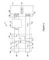
- FIG. 2provides a schematic view of an exemplary ventilation system 50 that may be incorporated into the HVAC system 4 as described herein with reference to FIG. 1 .
- the ventilation system 50may be a demand control ventilation system such as shown and described in U.S. Pat. No. 8,364,318 entitled “DEMAND CONTROL VENTILATION SYSTEM WITH FAN SPEED CONTROL”, which is incorporated herein by reference in its entirety for all purposes, but this is not required. It will be generally understood that different types of ventilation systems may be incorporated in to the HVAC system 4 , as described herein, depending upon the building design and the ventilation needs of the building.
- the ventilation system 50may be located upstream of the one or more HVAC components 6 such as, for example, a heating and/or an air conditioning unit, but this is not required.
- the ventilation system 50may include an outside air intake 58 and/or an exhaust vent 60 .
- a return air stream 62may be provided for drawing return air from the inside space of the building 2 through one or more return registers 64 .
- the illustrative HVAC system 4also includes a fan 69 , which may be a single, multiple or infinitely variable multiple speed fan, which can be controlled by a controller (e.g. HVAC controller 18 ) to induce a desired air flow through one or more HVAC components 6 such as, for example, a furnace or air conditioning unit and to the building 2 as shown at 66 through one or more supply registers 68 .
- a controllere.g. HVAC controller 18
- the ventilation system 50may employ one or more dampers to control air flows within the various ducts of the ventilation system 50 of the HVAC system 4 .
- dampersmay include an exhaust damper 70 to regulate the fraction of the return air stream 62 that is exhausted 71 from the building 2 , an intake damper 72 to regulate the flow of an incoming outside air stream 73 into the building 2 , and/or a return damper 74 to regulate the flow of the retained return air stream 75 to mix with the incoming outside air stream 73 .
- the dampers 70 , 72 , and/or 74may be mechanically coupled together to open and close in a coordinated manner, but this is not required.
- dampers 70 and 72may open and close together or in sequence, and damper 74 may open and close in an opposite manner to dampers 70 and 72 . It will be generally understood that more or fewer of the dampers 70 , 72 , and 74 may be employed, depending on the HVAC system 4 , the size of the building 2 , and/or the building's ventilation requirements.
- the ventilation system 50including the dampers 70 , 72 , 74 and associated duct work, may be included in an economizer. Under some conditions, such an economizer may be used to provide free cooling by mixing cooler incoming outside air 73 with the sometimes warmer retained return air 75 to provide a cooler mixed air stream 82 .
- the HVAC system 4may include a heat exchanger generally shown at 84 to transfer heat energy between the incoming outside air stream 73 and the exhausted air stream 71 , which may be useful under some operating conditions.
- FIG. 3is a schematic view of an illustrative HVAC control system 100 that facilitates remote access and/or control of the HVAC system 4 , as shown in FIG. 1 .
- the HVC system 4may incorporate a ventilation system such as, for example, ventilation system 50 as shown in FIG. 2 .
- the illustrative HVAC control system 100may include an HVAC controller, as for example, HVAC controller 18 (see FIG. 1 ) that is configured to communicate with and control one or more components 6 of the HVAC system 4 .
- the HVAC controller 18may be configured to communicate with and/or control the one or more dampers 70 , 72 , and/or 74 of the ventilation system 50 of the HVAC system 4 to ventilate and, in some instances, provide free heating and/or cooling to the building 2 .
- the HVAC controller 18may communicate with the one or more components 6 of the HVAC system 4 and/or the one or more dampers of the ventilation system 50 via a wired or wireless link. Additionally, the HVAC controller 18 may be adapted to communicate over one or more wired or wireless networks that may facilitate remote access and/or control of the HVAC controller 18 via another device such as a smart phone, a PDA, a tablet computer, a laptop or personal computer, wireless network-enabled key fobs, an e-reader and/or the like. As shown in FIG. 3 , the HVAC controller 18 may include a first communications port 102 for communicating over a first network 104 , and in some cases, a second communications port 106 for communicating over a second network 108 .
- the first network 104may be a wireless local area network (LAN), and the second network 108 (when provided) may be a wide area network or global network (WAN) including, for example, the Internet.
- the wireless local area network 104may provide a wireless access point and/or a network host device that is separate from the HVAC controller 18 .
- the wireless local area network 104may provide a wireless access point and/or a network host device that is part of the HVAC controller 18 .
- the wireless local area network 54may be an ad-hoc wireless network, but this is not required.
- remote access and/or control of the HVAC controller 18may be provided over the first network 104 and/or the second network 108 .
- a variety of remote wireless devices 112may be used to access and/or control the HVAC controller 18 from a remote location (e.g. remote from HVAC Controller 18 ) over the first network 104 and/or second network 108 including, but not limited to, mobile phones including smart phones, PDAs, tablet computers, laptop or personal computers, wireless network-enabled key fobs, e-readers and the like.
- the remote wireless devices 112are configured to communicate wirelessly over the first network 104 and/or second network 108 with the HVAC controller 18 via one or more wireless communication protocols including, but not limited to, cellular communication, ZigBee, REDLINKTM, Bluetooth, WiFi, IrDA, dedicated short range communication (DSRC), EnOcean, and/or any other suitable common or proprietary wireless protocol, as desired.
- wireless communication protocolsincluding, but not limited to, cellular communication, ZigBee, REDLINKTM, Bluetooth, WiFi, IrDA, dedicated short range communication (DSRC), EnOcean, and/or any other suitable common or proprietary wireless protocol, as desired.
- the HVAC controller 18may be programmed to communicate over the second network 108 with an external web service hosted by one or more external servers 116 .
- an external web serviceis Honeywell's TOTAL CONNECTTM web service.
- the HVAC controller 18may be configured to upload selected data via the network 108 to the external web service where it may be collected and stored on the external server 66 .
- the datamay be indicative of the performance of the HVAC system 4 .
- the datamay be indicative of indoor air quality and/or outdoor air quality (e.g. temperature, humidity, CO concentration, particulate contamination (dust, pollen, etc)).
- the HVAC controller 18may be configured to receive and/or download selected data, settings and/or services including software updates from the external web service over the second network 108 .
- the data, settings and/or servicesmay be received automatically from the web service, downloaded periodically in accordance with a control algorithm, and/or downloaded in response to a user request.
- the HVAC controller 18may be configured to receive and/or download an HVAC operating schedule and operating parameter settings such as, for example, temperature set points, humidity set points, comfort and/or economy settings, user-specified air quality thresholds, start times, end times, schedules, window frost protection settings, and/or the like.
- the HVAC controller 18may receive outdoor air quality data.
- Exemplary outdoor air quality datamay include, but is not limited to a current outdoor temperature and/or outdoor humidity, weather related data, pollen forecast and/or pollen count, a current air pollutant concentration, an air quality index and/or air quality alert, a smog alert, and/or the like.
- An air pollutant concentrationmay include an ozone concentration, a particulate matter concentration, a carbon monoxide concentration, a nitrogen oxides (NO x ) concentration, a sulfur dioxide concentration, and/or a lead concentration, but not limited to these.
- the weather related datamay include a current weather forecast and/or may include severe weather alerts and other outdoor air quality risks such as, for example, a UV index, a heat index, a heat advisory, a wind chill, wind direction and/or wind speed.
- the weather datamay be provided to the HVAC controller 18 by a different external server such as, for example, a web server maintained by the National Weather Service.
- the external server 66may collect appropriate air quality data from one or more other servers, and may deliver data to the HVAC controller 18 .
- the HVAC controller 18may perform some or all of the determination of whether ventilation is desired based on internal and/or external air quality.
- the external server 66may perform some or all of the determination of whether ventilation is desired based on internal and/or external air quality, and may communicate results to the HVAC controller 18 . These are just some examples.
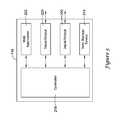
- FIG. 4is a schematic view of an illustrative HVAC controller 18 of a thermal comfort control system.
- the HVAC controller 18may be a thermostat, but this is not required.
- the HVAC controller 18may be accessed and/or controlled from a remote location over a network 108 ( FIG. 3 ) using a mobile wireless device 112 such as, for example, a smart phone, a PDA, a tablet computer, a laptop or personal computer, a wireless network-enabled key fob, an e-reader, and/or the like.
- the illustrative HVAC controller 18may include an input port 102 for communicating with one or more internal and/or remotely located sensors.
- the input port 102may be in communication with one or more internal sensors.
- the input port 102may be adapted to receive a signal indicative of a measure related to an environmental condition inside or outside of the building.
- the input port 102may receive the measure related to an environmental condition inside or outside of the building over a wireless network such, as for example, a wireless LAN, but this is not required.
- the network port 106may be a wired communications port.
- the network port 106may be a wireless communications port including a wireless transceiver for sending and/or receiving signals over a wireless network such as for example a wireless local area network (LAN) or a wide area network (WAN) such as, for example, the Internet 108 .
- LANwireless local area network
- WANwide area network
- the network port 106may be in communication with a wired or wireless router or gateway for connecting to the network 108 , but this is not required.
- the router or gatewaymay be integral to the HVAC controller 18 or may be provided as a separate device.
- the illustrative HVAC controller 18may include a processor (e.g. microprocessor, microcontroller, etc.) 114 and a memory 122 .
- the processor 114may be in communication the input port 102 and/or the network port 106 and with the memory 122 .
- the processor 114 and the memory 122may be situated within a housing 120 that may include at least one bracket for mounting the HVAC controller 18 to a wall located within the building or structure.
- the HVAC controller 18may include a user interface 118 including a display, but this is not required. In some instances, the user interface 118 may be secured relative to the housing 120 . In other instances, the user interface 118 may be located at a remote device such as any one of the remote devices disclosed herein.
- HVAC controller 18may include a timer (not shown). The timer may be integral to the processor 114 or may be a separate component.
- the HVAC controller 18may optionally include an input/output block (I/O block) 128 for receiving one or more signals from the HVAC system 4 and/or for providing one or more control signals to the HVAC system 4 .
- the I/O block 128may communicate with one or more HVAC components 6 of the HVAC system 4 .
- the I/O block 128may communicate with another controller, which is in communication with one or more HVAC components of the HVAC system 4 , such as a zone control panel in a zoned HVAC system, equipment interface module (EIM), or any other suitable building control device.
- EIMequipment interface module
- the illustrative HVAC controller 18may include an internal temperature sensor 130 located within the housing 120 , but this is not required.
- the HVAC controllermay also include an internal humidity sensor 132 located within the housing 120 , but this is also not required.
- the temperature sensor 130 and/or the humidity sensor 132may be coupled to the input port 102 which, in turn, is coupled to the processor 114 .
- the HVAC controller 18may communicate with one or more remote temperature sensors, humidity sensors, occupancy and/or other sensors located throughout the building or structure via, for example, the input port 102 and/or network port 106 . Additionally, in some cases, the HVAC controller may communicate with a temperature sensor and/or humidity sensor located outside of the building or structure for sensing an outdoor temperature and/or humidity if desired.
- the HVAC controller 18may receive at least one of a measure related to an indoor temperature inside the building or structure, a measure related to an indoor humidity inside the building or structure, and a measure related to an outdoor temperature and/or outdoor humidity outside of the building or structure.
- the HVAC controller 18may receive outdoor air quality related data including data indicative of an outdoor air quality parameter via the network port 106 .
- the outdoor air quality related datamay include a current outdoor temperature and/or outdoor humidity, weather related data, pollen forecast and/or pollen count, a current air pollutant concentration, an air quality index and/or air quality alert, a smog alert, and/or the like.
- An air pollutant concentrationmay include an ozone concentration, a particulate matter concentration, a carbon monoxide concentration, a nitrogen oxides (NO x ) concentration, a sulfur dioxide concentration, and/or a lead concentration, but not limited to these. Because of their possible effect on public health, these six common air pollutants are monitored by different agencies and reported by to the Environmental Protection Agency (EPA).
- EPAEnvironmental Protection Agency
- the weather related datamay include a current or future weather forecast and/or may include severe weather alerts and other outdoor air quality risks such as, for example, a UV index, a heat index, a wind chill, wind direction and/or wind speed. Severe weather alerts may include, but are not limited to, such as for example, a thunderstorm watch or warning, a tornado watch or warning, a flash flood watch or warning, and/or the like. These are just some examples of outdoor air quality related data that may be received by the HVAC controller 18 . Such severe weather alerts and/or information about other air quality risks may be displayed as an alert to the user via the display of the HVAC controller 18 .
- an air quality alertmay also be displayed to the user via the display of the HVAC controller 18 .
- the air quality alertmay indicate the short term and/or long term health risks associated with the air quality alert.
- the processor 114may operate in accordance with an algorithm that controls or at least partially controls one or more HVAC components of an HVAC system such as, for example, HVAC system 4 shown in FIG. 1 .
- the processor 114may operate in accordance with a control algorithm that provides temperature set point changes, humidity set point changes, schedule changes, air quality thresholds, start and end time changes, window frost protection setting changes, operating mode changes, ventilation changes, and/or the like.
- At least a portion of the control algorithmmay be stored locally in the memory 122 of the HVAC controller 18 and, in some cases, may be received from an external web service over the second network 108 .
- the control algorithm (or portion thereof) stored locally in the memory 122 of the HVAC controller 18may be periodically updated in accordance with a predetermined schedule (e.g.
- control algorithmmay include settings such as set points.
- the processor 114may operate according to a first operating mode having a first temperature set point, a second operating mode having a second temperature set point, a third operating mode having a third temperature set point, and/or the like.
- the first operating modemay correspond to an occupied mode and the second operating mode may correspond to an unoccupied mode.
- the third operating modemay correspond to a holiday or vacation mode wherein the building or structure in which the HVAC system 4 is located may be unoccupied for an extended period of time.
- the third operating modemay correspond to a sleep mode wherein the building occupants are either asleep or inactive for a period of time. These are just some examples. It will be understood that the processor 114 may be capable of operating in additional modes as necessary or desired.
- the number of operating modes and the operating parameter settings associated with each of the operating modesmay be established locally through a user interface, and/or through an external web service and delivered to the HVAC controller via the second network 108 where they may be stored in the memory 122 for reference by the processor 114 .
- the processor 114may operate according to one or more predetermined operating parameter settings associated with a user profile for an individual user.
- the user profilemay be stored in the memory 122 of the HVAC controller 18 and/or may be hosted by an external web service and stored on an external web server.
- the user profilemay include one or more user-selected settings for one or more operating modes that may be designated by the user.
- the user profilemay include one or more air quality thresholds that may be specified by the user and which, in some cases may be utilized by the processor to determine and/or anticipate the ventilation needs of the building for when the HVAC system 4 is operating in a selected operating mode.
- the processor 114may operate according to a first operating mode having a first temperature set point associated with a first user profile, a second operating mode having a second temperature set point associated with the first user profile, a third operating mode having a third temperature set point associated with the first user profile, and/or the like.
- the first operating modemay correspond to an occupied mode
- the second operating modemay correspond to an unoccupied mode
- the third operating modemay correspond to a vacation or extended away mode wherein the building or structure in which the HVAC system 4 is located may be unoccupied for an extended period of time.
- multiple user profilesmay be associated with the HVAC controller 18 .
- the processor 114may be programmed to include a set of rules for determining which individual user profile takes precedence for controlling the HVAC system when both user profiles are active.
- the user interface 118when provided, may be any suitable user interface that permits the HVAC controller 18 to display and/or solicit information, as well as accept one or more user interactions with the HVAC controller 18 .
- the user interface 118may permit a user to locally enter data such as temperature set points, humidity set points, air quality thresholds for one or more air quality parameters, starting times, ending times, schedule times, diagnostic limits, responses to alerts, and the like.
- the user interface 118may be a physical user interface that is accessible at the HVAC controller 18 , and may include a display and/or a distinct keypad.
- the displaymay be any suitable display.
- a displaymay include or may be a liquid crystal display (LCD), and in some cases a fixed segment display or a dot matrix LCD display.
- the user interface 118may be a touch screen LCD panel that functions as both display and keypad. The touch screen LCD panel may be adapted to solicit values for a number of operating parameters and/or to receive such values, but this is not required.
- the user interface 118may be a dynamic graphical user interface.
- the user interface 118need not be physically accessible to a user at the HVAC controller 18 .
- the user interface 118may be a virtual user interface that is accessible via the first network 104 and/or second network 108 using a mobile wireless device such as one of those devices 112 previously described herein.
- the virtual user interfacemay include one or more web pages that are broadcasted over the first network 104 (e.g. LAN) by an internal web server implemented by the processor 114 . When so provided, the virtual user interface may be accessed over the first network 104 using a remote wireless device 112 such as any one of those listed above.
- the processor 114may be configured to display information relevant to the current operating status of the HVAC system 4 including the current operating mode, temperature set point, actual temperature within the building, outside temperature, outside humidity, and/or the like. Additionally, the processor 114 may be configured to display information relevant to the current indoor and/or outdoor air quality including an air quality index or alert, air pollutant concentrations, UV index, wind direction and wind speed, smog alerts, pollen forecast and/or pollen count, weather forecast data including any weather related alerts, and/or the like. In some instances, this information may be displayed to the user via a dashboard that displays multiple data and alerts in a single screen.
- the dashboardmaybe a user interactive dashboard that may permit a user to select a data item or alert for additional information.
- the processor 114may also be configured to display or transmit one or more messages to the user regarding the ventilation needs and/or status of the building. Additionally, the processor 114 may be configured to receive and accept any user inputs entered via the virtual user interface 118 including temperature set points, humidity set points, air quality thresholds, starting times, ending times, schedule times, window frost protection settings, diagnostic limits, responses to alerts, and the like.
- the virtual user interfacemay include one or more web pages that are broadcasted over the second network 108 (e.g. WAN or the Internet) by an external server (e.g. web server 116 ).
- the one or more web pages forming the virtual user interfacemay be hosted by an external web service and associated with a user account having one or more user profiles.
- the external server 116may receive and accept any user inputs entered via the virtual user interface and associate the user inputs with a user's account on the external web service.
- the external web servermay update the control algorithm, as applicable, and transmit at least a portion of the updated control algorithm over the second network 108 to the HVAC controller 18 where it is received via the second network port 106 and may be stored in the memory 122 for execution by the processor 114 .
- the memory 122 of the illustrative HVAC controller 18may be in communication with the processor 114 .
- the memory 122may be used to store any desired information, such as the aforementioned control algorithm, set points, schedule times, air quality thresholds, and the like.
- the memory 122may be any suitable type of storage device including, but not limited to, RAM, ROM, EPROM, flash memory, a hard drive, and/or the like.
- the processor 114may store information within the memory 122 , and may subsequently retrieve the stored information from the memory 122 .
- the processor 114may be programmed to determine, at least in part, the ventilation needs of the building or structure 2 .
- the ventilation needs of the buildingmay include a current or future time period when ventilation may be desirable or beneficial. Additionally, the ventilation needs may include a current or future time period when ventilation is not required or recommended. It will be generally understood that in some cases a current time period may overlap, at least in part, with a future time period.
- the processor 114may be programmed to determine and/or predict when window ventilation is recommended to ventilate the building to improve and/or maintain an indoor air quality of the building 2 .
- the processor 114may be configured to determine and/or predict when operation of a ventilation system such as that shown in FIG. 2 and/or an economizer is desired to improve and/or maintain an indoor air quality of the building 2 .
- the processor 114may also be programmed to determine if a combination of window ventilation and mechanical ventilation is desirable. Additionally, the processor 114 may be configured to determine and/or predict when ventilation (window, mechanical, or a combination thereof) is no longer needed and/or recommended.
- the processor 114may be programmed to determine and/or predict the ventilation needs of the building or structure 2 based on a number of different parameters indicative of indoor or outdoor air quality including, but not limited to an indoor temperature, an indoor humidity, an outdoor temperature, an outdoor humidity, a current or future weather forecast, a pollen forecast and/or pollen count, a current air pollutant concentration, an air quality index and/or air quality alert, a smog alert, one or more user-specified air quality thresholds, and/or the like. In some instances, the processor 114 may determine that ventilation is needed at a current time (e.g. now) and for some predetermined amount of time into the future extending beyond the current time. The predetermined period of time may range from about 15 minutes up to about 5 days, but not limited to this.
- the processor 114may be programmed to determine and/or predict the ventilation needs of the building 2 based, at least in part, on a measure indicative of indoor air quality, a measure indicative of outdoor air quality, and a user-specified air quality threshold.
- the user-specified air quality thresholdmay be accepted from a user via the user interface 118 of the HVAC controller 18 and stored in the memory 122 .
- the user-specified air quality thresholdmay relate to an indoor air quality parameter and/or an outdoor air quality parameter.
- Exemplary indoor air quality parametersmay include an indoor temperature and an indoor humidity.
- Exemplary outdoor air quality parametersmay include a current outdoor temperature and/or outdoor humidity, weather related data, pollen forecast and/or pollen count, a current air pollutant concentration, an air quality index and/or air quality alert, a smog alert, and/or the like.
- An air pollutant concentrationmay include an ozone concentration, a particulate matter concentration, a carbon monoxide concentration, a nitrogen oxides (NO x ) concentration, a sulfur dioxide concentration, and/or a lead concentration, but not limited to these.
- the weather related datamay include a current or future weather forecast and/or may include severe weather alerts and other outdoor air quality risks such as, for example, a UV index, a heat index, a wind chill, wind direction and/or wind speed.
- Severe weather alertsmay include, but are not limited to, such as for example, a thunderstorm watch or warning, a tornado watch or warning, a flash flood watch or warning, and/or the like. These are just some examples.
- the user-specified air quality parameter thresholdrelates to an outdoor air quality parameter such as discussed herein.
- the processor 114may be programmed to solicit and accept one or more air quality thresholds from a user via the user interface 118 of the HVAC controller 18 .
- the one or more air quality thresholds specified by the usermay be based on the user's needs and/or desired comfort level. For example, an allergy suffer may specify a lower threshold for a pollen count than someone who does not suffer from pollen allergies. Similarly, someone having poor respiratory health or an elderly person may specify a lower threshold for a smog alert level or air quality index level than an average adult having a good overall health profile. In yet another example, someone who cannot tolerate high humidity may specify a lower humidity threshold. These are just some examples.
- the processor 114may be configured to rely on default values determined by the manufacturer or installer, which in some cases may be based on the needs of the average population.
- the default valuesmay be stored in the memory 122 where they may be retrieved by the processor 114 .
- the default values for one or more air quality parametersmay be altered by the processor 114 upon receiving a user-specified air quality parameter threshold from a user via the user interface 118 of the HVAC controller 18 .
- the processor 114may receive one or more signals indicative of an indoor air quality and/or outdoor air quality via the input port 102 and/or network port 106 .
- the processor 114may receive a first signal indicative of a measure of indoor air quality from either an internal sensor such as, for example, internal temperature sensor 130 or internal humidity sensor 132 and/or a from a temperature or humidity sensor external to the HVAC controller 18 , but located within the building 2 via the input port 102 .
- the processor 114may receive a second signal indicative of a measure of outdoor air quality via the input put 102 and/or, the network port 106 .
- the second signal indicative of a measure of outdoor air qualitymay be received from a sensor such as, for example, a temperature or humidity sensor located outside of the building or structure 2 , and may be indicative of an outdoor temperature, outdoor humidity and/or any other suitable outdoor air quality parameter.
- a sensorsuch as, for example, a temperature or humidity sensor located outside of the building or structure 2 , and may be indicative of an outdoor temperature, outdoor humidity and/or any other suitable outdoor air quality parameter.
- the processor 114may be programmed to receive a variety of weather related data and/or air quality data via the network port 106 .
- the processor 114may receive data indicative of a pollen forecast and/or a pollen count, a smog alert level, an air quality index level, an air pollutant concentration level, a dew point, a wind speed and/or wind direction, current weather conditions, a future weather forecast, any weather related alerts including a severe weather alert, wind chill advisory, heat advisory and/or the like, a UV index value, a chance percent of precipitation, and/or any other suitable weather related data via the network port 106 .
- the various datamay be received from one or more external servers 66 that host such data such as, for example, a web server hosted by the NOAA's National Weather Service, AccuWeather.com (www.accuweather.com), California's South Coast Air Quality Management District, Colorado's Air Quality Control Commission, the National Allergy Bureau, and/or a web service (such Honeywell's TOTAL CONNECTTM Web Service) that collects and aggregates the appropriate data.
- a web servicesuch as, for example, a web server hosted by the NOAA's National Weather Service, AccuWeather.com (www.accuweather.com), California's South Coast Air Quality Management District, Colorado's Air Quality Control Commission, the National Allergy Bureau, and/or a web service (such Honeywell's TOTAL CONNECTTM Web Service) that collects and aggregates the appropriate data.
- regional air quality management agencies or reporting agenciesmay provide data indicative of smog alert levels, air quality index levels, air pollutant concentrations, and/or pollen counts.
- the processor 114may utilize the weather and/or air quality data received via the network when determining and/or anticipating the current and/or future ventilation needs of the building 2 .
- the processor 114may receive data indicative of current weather conditions and may determine and/or anticipate the ventilation needs of the building 2 based, at least in part, on the current weather conditions in addition to a user-specified air quality threshold parameter value and measures related to an indoor air quality and an outdoor air quality.
- the processor 114may receive data indicative of a smog alert level and may determine and/or anticipate the ventilation needs of the building 2 based, at least part, on the smog alert level.
- the processor 114may receive data indicative of a current pollen count and may determine and/or anticipate the ventilations needs of the building 2 based, at least in part, on the current pollen count. In still yet another example, the processor 114 may receive indicative of one or more air pollutant concentrations and may determine and/or anticipate the ventilation needs of the building 2 based, at least in part, on the air pollutant concentrations. These are just some examples.
- the processor 114may be programmed to determine and/or anticipate the ventilation needs of the building 2 based on a combination of a number of different parameters including, but not limited to one or more measures related to an indoor air quality and/or an outdoor air quality, one or more user specified air quality thresholds, and weather and/or air quality related data.
- the processor 114may be programmed to compare the weather and/or air quality data received via the network port 106 to air quality thresholds, including any user-specified air quality thresholds, that are stored in the in memory 122 and, based at least in part on the comparison, determine and/or anticipate the current and/or future ventilation needs of the building 2 . For example, if the processor 114 determines that an air quality index value is lower than a user-specified threshold for an air quality index, then the processor 114 may determine that ventilating with fresh air from the outside is recommended or desired. Ventilation of the building may be accomplished by opening one or more windows 5 in the building 2 and/or by operating a ventilation system which draws in fresh air from outside the building 2 as shown and described in reference to FIG. 2 .
- ventilation of the buildingmay be accomplished by automatically opening one or more power operated windows 5 in the building 2 .
- the processor 114may display a message to the user via the user interface 118 of the HVAC controller recommending that the user manually open one or more windows 5 in the building 2 for ventilation.
- the processor 114may transmit a message to the user via SMS text message or email recommending that the user manually open one or more windows 5 in the building 2 for ventilation.
- the processormay display or transmit a message to the user recommending that the user close any open windows 5 or cease operation of any ventilation equipment.
- the processor 114may display or transmit a message notifying the user that ventilation is no longer necessary and/or recommended and may automatically close one or more windows and/or cease operation of a ventilation system associated with the building 2 . Additionally, in some cases, the processor 114 may cause the HVAC controller 18 to control one or more HVAC controller to regulate the environmental conditions within the building according to an operating schedule previously stored in the memory of the HVAC controller 18 .
- the processor 114may be configured to prioritize a user-specified air quality parameter threshold over measures related to an indoor air quality and an outdoor air quality when determining the ventilation needs of the building 2 . For example, if the outdoor temperature is lower than an indoor temperature, it would be generally expected that the processor 114 may determine that window ventilation is recommended. However, if a pollen count is higher than a user-specified threshold parameter value for the pollen count then, based on the higher priority assigned to the user specified threshold parameter which, in this case, is a pollen count, the processor 114 may determine that window or other ventilation is not recommended. This is just one example.
- the processor 114may be configured to solicit and accept user-determined priority for a number of different parameters including, but not limited to, one or more measures related to an indoor air quality and/or an outdoor air quality, one or more user specified air quality thresholds, and/or a variety of weather and/or air quality related data.
- the processor 114may be programmed to assign a user-determined priority or weight to a number of different parameters related to an indoor air quality and/or an outdoor air quality.
- the processor 114may use the weighted indoor air quality parameter values and/or outdoor air quality parameter values when determining the indoor air quality and the outdoor air quality and/or when comparing the indoor air quality to the outdoor air quality when determining the ventilation needs of the building 2 .
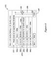
- Equation 1is an exemplary equation that may be used by the processor 114 when determining an outdoor air quality.
- Each of the parameters used to determine an outdoor air quality valuemay be assigned a weight based, at least in part, on a user-determined priority for each of the different parameters.
- the outdoor air quality valuemay be at least a function of the sum of each of the different parameter values and in some cases, may be an average value. A normalization factor could also be used.
- Outdoor Air Qualityw t Outdoor Air Temp+ w hum Outdoor Humidity+ w p Pollen Count+ w AQI Air Quality Index Eq. 1
- Equation 2is an exemplary equation that may be used by the processor 114 when determining an outdoor air quality.
- Each of the parameters used to determine an outdoor air quality valuemay be assigned a weight based, at least in part, on a user-determined priority for each of the different parameters.
- the outdoor air quality valuemay be at least a function of the sum of each of the different parameter values and in some cases, may be an average value. A normalization factor could also be used.
- Indoor Air Qualityw t Indoor Air Temp+ w hum. Indoor Humidity+ w co2 CO 2 +w CO CO Eq. 2
- the processor 114may be programmed to ventilate the building or recommend ventilation of the building when the processor 114 determines that the outdoor air quality is greater than the indoor air quality.
- ventilating the building 2maybe less energy efficient than continuing to operate the HVAC system 4 according to its current program.
- the processor 114may be configured to prompt the user to enter their preference as to ventilating the building using outside air to maintain or improve the indoor air quality, even when it is less energy efficient to do so.
- the processor 114may present an option to the user via the user interface 118 for the user to override a more energy efficient operation of the HVAC system 4 in favor of increasing the indoor air quality of the building 2 .
- the override of a more energy efficient operation configuration in favor of maintaining or increasing the indoor air qualityis temporary.
- the processor 114may also be programmed to determine an amount of time in which ventilation is needed and/or recommend based on one or more user-specified air quality parameter thresholds and/or any weather related or air quality data, as described herein.
- the amount of time determined for ventilationmay be based, at least in part, on one or more user-specified air quality thresholds and any weather and/or air quality data received via the network port 106 .
- the processor 114may also be configured to predict when ventilation is recommended based, at least in part, on any weather and/or air quality data received via the network port 106 .
- the processor 114may be configured to automatically transmit one or more command signals to an IAQ component or other HVAC component 6 via the input/output block 128 to ventilate the building 2 .
- the building 2may be ventilated by opening one more powered windows and/or operation of mechanical ventilation system.
- the processor 114may be configured to notify the user that ventilation is recommended and/or needed.
- the processor 114may be configured to notify that the user that the building 2 is currently being ventilation and may provide an amount of time for ventilation.
- the processor 114may be configured to transmit a data package to a user via the input port 102 and/or network port 106 .
- the data package transmitted to the usermay be in the form of a SMS text message or an email, and may notify the user to operate an IAQ component or that window ventilation is recommended.
- the processor 114may be configured to display a message or alert to the user via the user interface 118 of the HVAC controller 18 indicating the need for ventilation.
- the messagemay instruct the user to operate any IAQ components such as, for example, a mechanical ventilation system and/or economizer or, in some cases, may indicate that window ventilation is recommended.
- the messagemay notify the user that the HVAC controller 18 is commencing operation of any ventilation equipment and/or opening any power operated windows 5 located within the building 2 .
- the messagemay indicate the length of time desired or needed for adequate ventilation and/or may include a prediction as to when conditions for ventilation may be favorable.
- Another pre-set or customized programmay be selected by a user when the building is occupied above typical levels (e.g., when the occupants are hosting a gathering), and may cause the processor 114 transmit one or more command signals to an IAQ component or other HVAC component 6 to increase ventilation, lower indoor humidity and, in some cases, lower the temperature within the building.
- Still another pre-set or customized programmay be selected by a user for operating the HVAC components 6 , including any IAQ components during allergy season when pollen count levels are expected to be elevated, and may cause the processor 114 to transmit one or more command signals to an IAQ component or other HVAC component 6 to minimize outdoor ventilation and increase the blower speed within the building 2 when the pollen count has reached a pre-determined level.
- the HVAC controller 18may be programmed to communicate over the network 108 with an external web service hosted by one or more external servers 116 .
- an external web serviceis Honeywell's TOTAL CONNECTTM web service.
- the server 116may be configured to determine the ventilation needs of the building in which the HVAC controller 18 is located based, at least in part, on data received from one or more sensors indicative of the environmental conditions inside of the building, outside of the building, and/or weather related data including air quality data sometimes received from another web server such as a National Weather Service web server which may also be in communication with the server 116 and/or HVAC controller 18 .
- the server 116may also be configured to receive one or more user specified air quality thresholds that may provided by the user via the user interface 118 of the HVAC controller 18 and/or via one or more remote devices 112 .
- the one or more user specified air quality thresholdsmay also be used by the server 116 when determining the ventilation needs of the building 2 .
- the user interface 118may be located at the HVAC controller 18 or provided at a remote device 112 .
- FIG. 5is a schematic view of an external server 116 for hosting an external web service as discussed herein.
- the external server 116may be in communication with the HVAC controller 18 over a network 108 such as, for example, the Internet.
- the external server 116can include at least one input/output port 220 for sending and/or receiving data over the network 108 to and from the HVAC controller 18 and/or another remote device 112 .
- the external server 116may send and/or receive data to and from another web server over the network 108 via the input/output port 220 .
- a usermay respond to alerts and may enter or change various HVAC operating parameters including, but not limited, to temperature set points, humidity set points, starting times, ending times, schedule times, diagnostic limits, and/or the like, as well as respond to one or more alerts. Additionally, through the one or more web pages, a user may provide one or more air quality thresholds as discussed herein.
- an applicationmay be downloaded to a remote device 112 . The application may connect to the external server 116 and provide the virtual user interface 118 on the remote device.
- the controller 218may be programmed to determine if a combination of window ventilation and mechanical ventilation is desired. Additionally, the processor 114 may be configured to determine and/or anticipate when ventilation is no longer needed and/or recommended. The controller 218 may be programmed to determine and/or anticipate the ventilation needs of the building or structure 2 based on a number of different parameters indicative of indoor or outdoor air quality including, but not limited to an indoor temperature, an indoor humidity, an outdoor temperature, an outdoor humidity, a pollen forecast and/or a pollen count, a smog alert level, an air quality index level, a dew point, a wind speed and/or wind direction, current weather conditions, a future weather forecast, a chance percent of precipitation, a user-specified air quality parameter threshold value, and/or the like.
- indoor or outdoor air qualityincluding, but not limited to an indoor temperature, an indoor humidity, an outdoor temperature, an outdoor humidity, a pollen forecast and/or a pollen count, a smog alert level, an air quality index level, a dew point,
- the controller 218may be programmed to determine the ventilation needs of the building 2 based, at least in part, on a measure indicative of indoor air quality, a measure indicative of outdoor air quality, and one or more user-specified air quality thresholds.
- the user-specified air quality threshold(s)may be accepted from user via the user interface 118 of the HVAC controller 18 and stored in the memory 122 .
- the user interface 118may be provided by one or more web pages served up by the server 116 over a network 108 , which may be accessed at the HVAC controller 18 or by using a remote device 112 .
- the HVAC controller 18 and/or remote device 112may execute an application (app) that provides the user interface.
- the user-specified air quality thresholdmay relate to an indoor air quality parameter and/or an outdoor air quality parameter.
- Exemplary indoor air quality parametersmay include an indoor temperature and an indoor humidity.
- Exemplary outdoor air quality parametersmay include a current outdoor temperature and/or outdoor humidity, weather related data, pollen forecast and/or pollen count, a current air pollutant concentration, an air quality index and/or air quality alert, a smog alert, and/or the like.
- An air pollutant concentrationmay include an ozone concentration, a particulate matter concentration, a carbon monoxide concentration, a nitrogen oxides (NO x ) concentration, a sulfur dioxide concentration, and/or a lead concentration, but not limited to these.
- the weather related datamay include a current weather forecast and/or may include severe weather alerts and other outdoor air quality risks such as, for example, a UV index, a heat index, a wind chill, wind direction and/or wind speed. Severe weather alerts may include, but are not limited to, such as for example, a thunderstorm watch or warning, a tornado watch or warning, a flash flood watch or warning, and/or the like. These are just some examples.
- the user-specified air quality parameter thresholdrelates to an outdoor air quality parameter such as discussed herein.
- the controller 218 of the server 116may be programmed to solicit and accept one or more air quality parameter threshold(s) from a user via the user interface 118 of the HVAC controller 18 and/or via a virtual user interface on a remote device 112 .
- the one or more air quality parameter threshold(s) specified by the usermay be based on the user's needs and/or desired comfort level. For example, an allergy suffer may specify a lower threshold value for a pollen count than someone who does not suffer from allergies. Similarly, someone having poor respiratory health or an elderly person may specify a lower threshold value for a smog alert level or air quality index level than the average adult having a good overall health profile. In yet another example, someone who cannot tolerate high humidity may specify a lower threshold value for indoor humidity. These are just some examples.
- the controller 218may be configured to rely on default values determined by the manufacturer or the installer for a variety of air quality parameters. These default values may be stored in the data storage device 214 where they may be retrieved by the controller 218 . The default values for one or more air quality thresholds may be altered by the controller 218 upon receiving a user-specified air quality parameter threshold from a user via the user interface 118 of the HVAC controller 18 or via a virtual user interface.
- the controller 218may receive one or more signals indicative of an indoor air quality and/or outdoor air quality transmitted over the network 108 via the input/output port 220 .
- the one or more signals indicative of an indoor air quality and/or outdoor air qualitymay be transmitted by the HVAC controller 18 to the server 116 where they may be received by the controller 218 via the input/output port 220 .
- the one or more signals indicative of an indoor air quality and/or outdoor air qualitymay be transmitted by one or more network enabled sensors (e.g. sensors) which may be capable of transmitting and/or receiving signals indicative of indoor and/or outdoor environmental conditions over a network such as, for example, network 108 where they may be received by the controller 218 via the input/output port.
- the signalsmay be incorporated into a data transmission package which may contain additional data, but this is not required.
- the controller 218may be programmed to receive a variety of weather related data and/or air quality data via an additional input/output port 220 .
- the controller 218may receive data indicative of a pollen forecast and/or a pollen count, a smog alert level, an air quality index level, an air pollutant concentration level, a dew point, a wind speed and/or wind direction, current weather conditions, a future weather forecast, any weather related alerts including a severe weather alert, wind chill advisory, heat advisory, and/or the like, a UV index value, a chance percent of precipitation, and/or any other suitable weather related from another web server via the input/output port 220 .
- the various datamay be received from one or more external servers 66 that host such data such as, for example, a web server hosted by the NOAA's National Weather Service, AccuWeather.com (www.accuweather.com), California's South Coast Air Quality Management District, Colorado's Air Quality Control Commission, the National Allergy Bureau, and/or a web service (such Honeywell's TOTAL CONNECTTM Web Service) that collects and aggregates the appropriate data.
- a web servicesuch as, for example, a web server hosted by the NOAA's National Weather Service, AccuWeather.com (www.accuweather.com), California's South Coast Air Quality Management District, Colorado's Air Quality Control Commission, the National Allergy Bureau, and/or a web service (such Honeywell's TOTAL CONNECTTM Web Service) that collects and aggregates the appropriate data.
- regional air quality management agencies or reporting agenciesmay provide data indicative of smog alert levels, air quality index levels, air pollutant concentrations, and/or pollen counts.
- the controller 218may utilize any weather and/or air quality data received via the network when determining the ventilation needs of the building. For example, in some cases, the controller 218 may receive data indicative of current weather conditions and may determine the ventilation needs of the building 2 based, at least in part, on the current weather conditions in addition to a user-specified air quality threshold parameter value and measures related to an indoor air quality value received from the HVAC controller 18 . Similarly, the controller 218 may receive data indicative of a smog alert level and may determine and/or predict the ventilation needs of the building 2 based, at least part, on the smog alert level in addition to a user-specified air quality threshold.
- the controller 218may receive data indicative of a current pollen count and may determine and/or predict the ventilations needs of the building 2 based, at least in part, on the current pollen count in addition to a user-specified air quality threshold. In still yet another example, the controller 218 may receive indicative of one or more air pollutant concentrations and may determine and/or predict the ventilation needs of the building 2 based, at least in part, on the air pollutant concentrations. These are just some examples.
- the controller 218may be programmed to determine and/or anticipate the ventilation needs of the building 2 based on a combination of two or more different parameters including, but not limited to one or more measures related to an indoor air quality, one or more measures related to an outdoor air quality, and/or one or more user specified air quality thresholds.
- the controller 218may be programmed to compare the weather and/or air quality data received via the input/output port 220 to the air quality thresholds, including any user-specified air quality thresholds stored in the in memory 122 and, based at least in part on the comparison, determine the ventilation needs of the building 2 . In one example, if the controller 218 determines that an air quality index value is lower than a user-specified threshold for an air quality index, then the controller 218 may determine that ventilating with fresh air from the outside of the building is desirable or recommended. Ventilation of the building may be accomplished by, for example, opening one or more windows of the building and/or by operating a ventilation system which draws in fresh air from outside the building as shown and described in reference to FIG. 2 .
- ventilation of the buildingmay be accomplished by automatically opening one or more power operated windows 5 in the building 2 .
- the controller 218may display a message to the user via the user interface 118 of the HVAC controller recommending that the use manually open one or more windows 5 in the building 2 for ventilation.
- the controller 218may transmit a message to the user via SMS text message or email recommending that the user manually open one or more windows 5 in the building 2 for ventilation.
- the processormay display or transmit a message to the user recommending that the user close any open windows 5 or cease operation of any ventilation equipment.
- the controller 218may display or transmit a message notifying the user that ventilation is no longer necessary and/or recommended and may automatically close one or more windows and/or cease operation of a ventilation system associated with the building 2 . Additionally, in some cases, the controller 218 may cause the HVAC controller 18 to control one or more HVAC controller to regulate the environmental conditions within the building 2 according to an operating schedule previously stored on the server.
- the controller 218may be configured to prioritize user-specified air quality thresholds when determining the ventilation needs of the building. For example, if the outdoor temperature is lower than an indoor temperature, it would be generally expected that the controller 218 may determine that window (or other) ventilation is recommended. However, if a pollen count is higher than a user-specified parameter threshold for the pollen count, then based on the higher priority assigned to the user specified parameter threshold of pollen count (in this example), the controller 218 may determine that window (or other) ventilation is not recommended. This is just one example.
- the controller 218may be configured to display one or more web pages that are configured to solicit and/or accept a user-determined priority for two or more different parameters including, but not limited to, one or more measures related to an indoor air quality and/or an outdoor air quality.
- the controller 218when determining the ventilation needs of the building, may be programmed to assign a user-determined priority or weight to a number of different parameters related to an indoor air quality and/or an outdoor air quality.
- the processor 114may use the weighted indoor air quality parameter values and/or outdoor air quality parameter values when determining the indoor air quality and the outdoor air quality and/or when comparing the indoor air quality to the outdoor air quality when determining the ventilation needs of the building 2 .
- the controller 218may be configured to utilize Equations 1 and 2 when determining the ventilation needs of the building 2 , as described herein.
- the controller 218may be programmed to ventilate the building or recommend ventilation of the building when the controller 218 determines that the outdoor air quality is greater than the indoor air quality. Under certain circumstances, ventilating the building 2 maybe less energy efficient than continuing to operate the HVAC system 4 according to its current program. In some instances, the controller 218 may be configured to display one or more web pages that are configured to prompt the user to enter their preference as to ventilating the building using outside air to maintain or improve the indoor air quality, even when it is less energy efficient to do so. In other words, the controller 218 may display an option to the user via the one or more web pages forming the user interface 118 for the user to override a more energy efficient operation of the HVAC system 4 in favor of increasing the indoor air quality of the building 2 . In many cases, the override of a more energy efficient operation configuration in favor of maintaining or increasing the indoor air quality is temporary.
- the controller 218may also be programmed to determine an amount of time in which ventilation is needed and/or recommend based on one or more user-specified air quality parameter thresholds and/or any weather related or air quality data, as described herein.
- the amount of time determined for ventilationmay be based, at least in part, on one or more user-specified air quality thresholds and any weather and/or air quality data received via the input/output port 220 .
- the controller 218may also be configured to predict when ventilation is recommended based, at least in part, on any weather and/or air quality data received via the input/output port 220 .
- the controller 218may transmit a data package to the HVAC controller 18 via the input/output port 220 , including a command to operate an IAQ component or other HVAC component 6 of the HVAC system 4 of the building 2 .
- the building 2may be ventilated by opening one more powered windows and/or operation of mechanical ventilation system.
- the controller 218may notify the user of the building that ventilation is recommended and/or needed and may specify an amount of time needed or recommended for adequate ventilation. Additionally, the controller 218 may notify the user that the building is currently being ventilated.
- the controller 218may be configured to transmit a data package to a user via the input/output port 220 .
- the data packagemay be in the form of a SMS text message or an email, and may instruct the user to operate an IAQ component or indicate that window ventilation is recommended.
- the controller 218may be configured to display a message or alert on the user interface 118 of the HVAC controller 18 indicating the desirability of ventilation.
- the user interface 118may be located at the HVAC controller 18 and/or provided at a remote device 112 such as any of those remote devices described herein.
- the messagemay instruct the user to operate any IAQ components such as, for example, a mechanical ventilation system and/or economizer or, in some cases, may indicate that window ventilation is recommended.
- the messagemay notify the user that the HVAC controller 18 is commencing operation of any ventilation equipment and/or opening any power operated windows 5 located within the building 2 . Additionally, the message may indicate the length of time desired or needed for adequate ventilation and/or may include a prediction as to when conditions for ventilation may be favorable.
- the controller 218may be programmed to follow one or more pre-set or customized programs for ventilating the building 2 .
- the pre-set or customized programsmay be utilized ventilate the building 2 under selected conditions, and may be selected by the user through the user interface 118 of the HVAC controller 18 .
- a first pre-set or custom programmay be selected by a user when a building occupant is ill, and may cause the controller 218 to control transmit one or more command signals via the input/output port 220 to an IAQ component or other HVAC component 6 to increase ventilation and humidity and, in some cases, maintain an elevated temperature overnight.
- Another pre-set or customized programmay be selected by a user when the building is occupied above typical levels (e.g., when the occupants are hosting a gathering), and may cause the controller 218 transmit one or more command signals via the input/output port 220 to an IAQ component or other HVAC component 6 to increase ventilation, lower indoor humidity and, in some cases, lower the temperature within the building.
- Still another pre-set or customized programmay be selected by a user for operating the HVAC components 6 , including any IAQ components during allergy season when pollen count levels are expected to be elevated, and may cause the controller 218 to transmit one or more command signals via the input/output port 220 to an IAQ component or other HVAC component 6 to minimize outdoor ventilation and increase the blower speed within the building 2 when the pollen count has reached a pre-determined level.
- FIGS. 6-7show exemplary screens 250 , 260 that may be displayed by the HVAC controller 18 and/or server 116 via a user interface (e.g. user interface 118 ), and that may be used to solicit and/or accept one or more air quality thresholds from a user.
- screen 260 of FIG. 7may be accessed through a menu screen such as, for example, menu screen 250 shown in FIG. 6 .
- Menu screen 250may include a table or a drop down menu 256 that includes one or more menu options 258 a - 258 e that may be selected by a user.
- the menu optionscan include an “Air Quality Settings” option 258 c .
- the “Air Quality Settings” menu option 258 cmay be available under an advanced setting menu option such as for example, menu option 258 e , but this is not required.
- selection of the “Air Quality Settings” menu option 258 cmay cause the processor 114 or controller 218 to display at least one additional screen 260 , shown in FIG. 7 , which may prompt select a user to select an air quality parameter from a menu including one or more selectable options 268 a - 268 f , where each selectable option 268 a - 268 f corresponds to a different air quality parameter.
- the one or more selectable options 268 a - 268 fmay be displayed in a table or in a drop down menu as shown, although this is not required. As shown in FIG.
- selectable options 268 a - 268 fmay correspond to an air quality index, a smog alert level, a pollen count, air pollutant concentration(s), a chance of precipitation, and a dew point, respectively. It will be generally understood that selectable options 268 a - 268 f may correspond to other air quality parameters depending upon the application and/or the needs of the consumer (e.g. humidity, etc.).
- selection of the “Air Quality Index” option 268 amay cause the processor 114 or controller 218 to display screen 270 , as shown in FIG. 8 , which may include a user prompt 272 that instructs the user to select an air quality threshold value.
- Screen 270may display a table 276 including a list of air quality index values and/or range of index values 280 a - 280 e .
- the table 276also include a descriptor 284 a - 284 e associated with each index value or range of index values 280 a - 280 e .
- the air quality index values or range of index values 280 a - 280 e and their related descriptors 284 a - 284 emay vary by country or region if desired. In some cases, the air quality index values or range of index values 280 a - 280 e and their related descriptors 284 a - 284 e may be color coded, but this is not required. In the example shown, the air quality index values or range of index values 280 a - 280 e include quantitative values, and their related descriptors 284 a - 284 e include qualitative descriptions. The qualitative descriptions 284 a - 284 e may aid a user in making a proper selection.
- screen 270may include a slider bar 288 including an indicator 292 that may interact with the index values 280 a - 280 e listed in table 276 .
- the usermay use the indicator 292 slider bar 288 to select an air quality threshold value.
- the indicator 292may indicate the actual air quality index value.
- a usermay simply select the desired air quality index value or range of values from the list of such values displayed by table 276 .
- the usermay select the done button 296 . Selection of the done button 296 may cause the processor 114 or controller 218 to store the air quality index threshold value in the memory 122 or 214 . Additionally, selection of the done button 296 may cause the processor 114 or controller 218 to return to the previous screen 260 from which the user may select another air quality parameter for inputting another user-specified air quality parameter threshold, as desired.
- the processor 114 or controller 218may display at least one additional screen 300 , as shown in FIG. 9 , that may prompt a user to assign a ranking or prioritize one or more air quality parameters.
- Screen 300may include a natural language prompt 302 that may prompt the user to assign a ranking or priority level on using a ranking scale 304 that may be displayed on screen 300 .
- the ranking scale 304 displayed on screen 300may be a star ranking scale, a ranking scale of 1 to 10, or a ranking scale of 1 to 5 (shown). These are just some examples. Other ranking scales may be utilized.
- ranking scale 304may include qualitative labels 306 a , 306 b indicating the high and low ends of the scales.
- a ranking scale 304may be displayed for each different air quality parameter 308 a - 308 d identified on screen 300 .
- each of the ranking scalesmay include a slider bar 310 and a slider control 312 that may be manipulated by a user to assign a ranking to each of the different air quality parameters. This is just one example.
- Other selection features, such as radio buttons,may be displayed and utilized by the user to assign a ranking or priority to one or more air quality parameters.
- the processor 114 or controller 218may programmed to only prompt a user to rank or prioritize a number of different air quality parameters.
- the processor 114 or the controller 218may be configured to display yet another screen 314 that may prompt a user to indicate their preference for prioritizing indoor air quality over energy efficiency. This may be applicable when the processor 114 or controller 218 determines that the outdoor air quality is greater than the indoor air quality, but energy efficiency of the building 2 may be compromised or decreased if ventilation is commenced.
- Screen 314may display a user prompt 316 that may query a user about their preference.
- Screen 314may include a first checkbox 318 a labeled “Yes” and a second checkbox 318 b labeled “No” that a user may user to indicate their preference.
- the processor 114 and the controller 218may be configured to store the user's preference in a memory.
- FIG. 11shows another exemplary screen 320 that may be displayed by the HVAC controller 18 and/or server 116 via a user interface (e.g. user interface 118 ).
- Screen 320may be displayed upon selection of the “IAQ Programs” selection option 258 d displayed on menu screen 250 shown in FIG. 6 .
- screen 320includes one or more selectable IAQ program options 324 a - 324 c that may be selected by a user.
- Each of the selectable IAQ program options 324 a - 324 ccorrespond to a pre-set or customized IAQ program that may be executed by the processor 114 or, in some cases, the controller 218 for operating one or more IAQ components or other HVAC components 6 for managing the indoor air quality of the building 2 under selected conditions.
- each of the selectable IAQ program options 324 a - 324 cinclude a descriptor which may aid a user in selecting the most appropriate program for the user's selected conditions.
- screen 320may also include a button labeled “Help” that when selected may cause the processor 114 or controller 218 to display additional information about each of the selectable options 324 a - 324 c .
- the usermay select the done button 332 .
- Selection of the done button 332may cause the processor 114 or controller 218 to execute the selected IAQ program. Additionally, selection of the done button 332 may cause the processor 114 or controller 218 to return to a previous screen (e.g. menu screen 250 ) from which the user may select another option, as desired.
- FIG. 12show exemplary screens that may be displayed to a user upon determining that ventilation is needed or desired.
- screen 400includes a user prompt 406 indicating that window ventilation is recommended.
- Screen 412 of FIG. 13includes a user prompt 416 instructing the user to operate a ventilation system.
- user prompt 416may include a recommended duration for operation of the ventilation system, but this is not required.
- screen 450may include a user message 456 predicting when conditions for ventilation are favorable.
- screen 450may also include a natural language prompt 460 that may query the user about ventilating the building.
- Screen 450may include a first checkbox 462 a labeled “Yes” and a second checkbox 462 b labeled “No” that a user may use to indicate their preference.
- the processor 114 or controller 218may send a signal to one or more IAQ components or one or more powered windows to ventilate the building.
- the exemplary screen 470 shown in FIG. 15is similar to that shown in FIG. 14 .
- screen 470includes a user message 476 that informs the user that ventilation conditions are favorable for a predetermined amount of time (e.g. next 36 hours). Ventilation may be carried out by operation of any mechanical ventilation equipment and/or by opening one or more manual or powered windows.
- the user message 476may also include a time indictor 480 indicating the amount of time the building is being ventilated. The amount of time displayed by the time indicator may vary depending upon the ventilation needs of the building 2 determined by the processor 114 or controller 218 , and may range from a few hours to several days.
- FIGS. 16 and 17show exemplary screens 500 , 530 that may be displayed by the processor 114 or controller 218 upon determining that ventilation is no longer needed and/or recommended.
- screen 500includes a first user message 506 that notifies a user that ventilation is no longer needed. Additionally, screen 500 may also include a second user message 510 that instructs a user to close any open windows.
- screen 530includes a first user message 536 that alerts a user that ventilation is no longer needed and/or recommended.
- the first user message 536may include a symbol 538 such as an exclamation point or other alert symbol displayed adjacent to and/or associated with the first user message. The symbol may visually alert the user that the user message 536 is being displayed.
- screen 530may include a second user message 540 that may query the user about resuming a normal or scheduled operation of the HVAC system 4 .
- Screen 530may include a first checkbox 542 a labeled “Yes” and a second checkbox 542 b labeled “No” that a user may use to indicate their preference.
- the processor 114 or controller 218may cause the HVAC controller 18 to send a signal to one or more HVAC components to resume operation according to an operating schedule of the HVAC systemn4 stored in memory.
- the notifications, alerts, and/or messages shown in connection with screens 400 , 412 , 450 , 470 , 500 and/or 530may also be transmitted via SMS text message or email to a user's remote device.
Landscapes
- Engineering & Computer Science (AREA)
- General Engineering & Computer Science (AREA)
- Mechanical Engineering (AREA)
- Chemical & Material Sciences (AREA)
- Combustion & Propulsion (AREA)
- Physics & Mathematics (AREA)
- Signal Processing (AREA)
- Mathematical Physics (AREA)
- Fuzzy Systems (AREA)
- Human Computer Interaction (AREA)
- Automation & Control Theory (AREA)
- General Physics & Mathematics (AREA)
- Air Conditioning Control Device (AREA)
Abstract
Description
Outdoor Air Quality=wtOutdoor Air Temp+whumOutdoor Humidity+wpPollen Count+wAQIAir Quality Index Eq. 1
Indoor Air Quality=wtIndoor Air Temp+whum.Indoor Humidity+wco2CO2+wCOCO Eq. 2
In some cases, the
Claims (17)
Priority Applications (1)
| Application Number | Priority Date | Filing Date | Title |
|---|---|---|---|
| US15/452,084US10458668B2 (en) | 2013-07-26 | 2017-03-07 | Air quality based ventilation control for HVAC systems |
Applications Claiming Priority (2)
| Application Number | Priority Date | Filing Date | Title |
|---|---|---|---|
| US13/952,256US9618224B2 (en) | 2013-07-26 | 2013-07-26 | Air quality based ventilation control for HVAC systems |
| US15/452,084US10458668B2 (en) | 2013-07-26 | 2017-03-07 | Air quality based ventilation control for HVAC systems |
Related Parent Applications (1)
| Application Number | Title | Priority Date | Filing Date |
|---|---|---|---|
| US13/952,256ContinuationUS9618224B2 (en) | 2013-07-26 | 2013-07-26 | Air quality based ventilation control for HVAC systems |
Publications (2)
| Publication Number | Publication Date |
|---|---|
| US20170176030A1 US20170176030A1 (en) | 2017-06-22 |
| US10458668B2true US10458668B2 (en) | 2019-10-29 |
Family
ID=52391144
Family Applications (2)
| Application Number | Title | Priority Date | Filing Date |
|---|---|---|---|
| US13/952,256Active2034-11-04US9618224B2 (en) | 2013-07-26 | 2013-07-26 | Air quality based ventilation control for HVAC systems |
| US15/452,084Active2033-12-05US10458668B2 (en) | 2013-07-26 | 2017-03-07 | Air quality based ventilation control for HVAC systems |
Family Applications Before (1)
| Application Number | Title | Priority Date | Filing Date |
|---|---|---|---|
| US13/952,256Active2034-11-04US9618224B2 (en) | 2013-07-26 | 2013-07-26 | Air quality based ventilation control for HVAC systems |
Country Status (1)
| Country | Link |
|---|---|
| US (2) | US9618224B2 (en) |
Cited By (9)
| Publication number | Priority date | Publication date | Assignee | Title |
|---|---|---|---|---|
| US20160187899A1 (en)* | 2013-07-29 | 2016-06-30 | Ambi Labs Limited | Climate controller |
| US20190108746A1 (en)* | 2017-10-05 | 2019-04-11 | Tamkang University | Indoor air quality control system |
| CN111503855A (en)* | 2020-04-29 | 2020-08-07 | 四川虹美智能科技有限公司 | Control system and control method of multi-split air conditioner |
| US11703818B2 (en) | 2020-08-03 | 2023-07-18 | Trane International Inc. | Systems and methods for indoor air quality based on dynamic people modeling to simulate or monitor airflow impact on pathogen spread in an indoor space and to model an indoor space with pathogen killing technology, and systems and methods to control administration of a pathogen killing technology |
| US20230366581A1 (en)* | 2022-05-11 | 2023-11-16 | Lennox Industries Inc. | Hvac system with indoor air quality monitoring and mitigation |
| US12018853B2 (en) | 2021-03-31 | 2024-06-25 | International Business Machines Corporation | Smart ventilation for air quality control |
| US12066192B2 (en) | 2018-11-29 | 2024-08-20 | Broan-Nutone Llc | Smart indoor air venting system |
| US12339021B2 (en) | 2022-01-19 | 2025-06-24 | Carrier Corporation | Method for increasing equipment effectiveness for healthy buildings |
| US12405018B2 (en) | 2019-01-07 | 2025-09-02 | Broan-Nutone Llc | System and method for controlling indoor air quality |
Families Citing this family (188)
| Publication number | Priority date | Publication date | Assignee | Title |
|---|---|---|---|---|
| US9722813B2 (en) | 2008-09-08 | 2017-08-01 | Tendril Networks, Inc. | Consumer directed energy management systems and methods |
| US8798796B2 (en)* | 2008-10-27 | 2014-08-05 | Lennox Industries Inc. | General control techniques in a heating, ventilation and air conditioning network |
| US10303035B2 (en) | 2009-12-22 | 2019-05-28 | View, Inc. | Self-contained EC IGU |
| US20210063836A1 (en) | 2017-04-26 | 2021-03-04 | View, Inc. | Building network |
| WO2018200702A1 (en) | 2017-04-26 | 2018-11-01 | View, Inc. | Tintable window system computing platform |
| US10678279B2 (en) | 2012-08-01 | 2020-06-09 | Tendril Oe, Llc | Optimization of energy use through model-based simulations |
| US9423779B2 (en) | 2013-02-06 | 2016-08-23 | Tendril Networks, Inc. | Dynamically adaptive personalized smart energy profiles |
| US9310815B2 (en) | 2013-02-12 | 2016-04-12 | Tendril Networks, Inc. | Setpoint adjustment-based duty cycling |
| US10070280B2 (en)* | 2016-02-12 | 2018-09-04 | Crowdcomfort, Inc. | Systems and methods for leveraging text messages in a mobile-based crowdsourcing platform |
| US9625922B2 (en) | 2013-07-10 | 2017-04-18 | Crowdcomfort, Inc. | System and method for crowd-sourced environmental system control and maintenance |
| US11394462B2 (en) | 2013-07-10 | 2022-07-19 | Crowdcomfort, Inc. | Systems and methods for collecting, managing, and leveraging crowdsourced data |
| US10541751B2 (en) | 2015-11-18 | 2020-01-21 | Crowdcomfort, Inc. | Systems and methods for providing geolocation services in a mobile-based crowdsourcing platform |
| US10796085B2 (en) | 2013-07-10 | 2020-10-06 | Crowdcomfort, Inc. | Systems and methods for providing cross-device native functionality in a mobile-based crowdsourcing platform |
| US10379551B2 (en) | 2013-07-10 | 2019-08-13 | Crowdcomfort, Inc. | Systems and methods for providing augmented reality-like interface for the management and maintenance of building systems |
| US9618224B2 (en) | 2013-07-26 | 2017-04-11 | Honeywell International Inc. | Air quality based ventilation control for HVAC systems |
| KR20150038978A (en)* | 2013-10-01 | 2015-04-09 | 엘지전자 주식회사 | heating, ventilation, and/or air conditioning controller |
| US10228837B2 (en)* | 2014-01-24 | 2019-03-12 | Honeywell International Inc. | Dashboard framework for gadgets |
| US9503623B2 (en) | 2014-06-03 | 2016-11-22 | Applied Minds, Llc | Color night vision cameras, systems, and methods thereof |
| US11743071B2 (en) | 2018-05-02 | 2023-08-29 | View, Inc. | Sensing and communications unit for optically switchable window systems |
| US20170154517A1 (en)* | 2014-07-04 | 2017-06-01 | Koninklijke Philips N.V. | Air quality alert system and method |
| US10871756B2 (en)* | 2014-08-26 | 2020-12-22 | Johnson Solid State, Llc | Temperature control system and methods for operating same |
| JP6459336B2 (en)* | 2014-09-19 | 2019-01-30 | パナソニックIpマネジメント株式会社 | Air information management device |
| US20160116181A1 (en)* | 2014-10-28 | 2016-04-28 | Airadvice For Homes, Inc. | Indoor air quality sense and control system |
| US20170350611A1 (en)* | 2014-12-24 | 2017-12-07 | Koninklijke Philips N.V. | Arrangement and method for air management of a room |
| US10247434B2 (en) | 2015-01-19 | 2019-04-02 | Lennox Industries Inc. | HVAC system and an HVAC controller configured to operate the HVAC system based on air pollutant data and user comfort |
| CN105635091A (en)* | 2015-02-12 | 2016-06-01 | 北京神器科技有限公司 | Remote calling method and system |
| FI128643B (en) | 2015-03-16 | 2020-09-30 | Air D Fin Oy | Intelligent ventilation system |
| CN104776557B (en)* | 2015-03-26 | 2018-02-13 | 深圳市久怡科技有限公司 | A kind of air treating method and device |
| CN104819599A (en)* | 2015-05-19 | 2015-08-05 | 周明 | Tiered energy use regional comprehensive energy recycling system |
| US10149114B2 (en) | 2015-07-07 | 2018-12-04 | Crowdcomfort, Inc. | Systems and methods for providing geolocation services in a mobile-based crowdsourcing platform |
| US10444712B2 (en)* | 2015-07-13 | 2019-10-15 | Tata Consultancy Services Limited | Method and system to optimize energy consumption in a zone with a multi-air handling unit (AHU) setup |
| CN105180368A (en)* | 2015-09-18 | 2015-12-23 | 珠海汉朗环境科技有限公司 | Air purifier and replacement reminding method and device of filter net of air purifier |
| KR20170038424A (en)* | 2015-09-30 | 2017-04-07 | 코웨이 주식회사 | System and method of estimating air quality using survey and air quality estimating server |
| US20170167743A1 (en)* | 2015-12-14 | 2017-06-15 | Carrier Corporation | System and method to reduce particulate pollutants in a conditioned space |
| US9989960B2 (en)* | 2016-01-19 | 2018-06-05 | Honeywell International Inc. | Alerting system |
| US11680721B2 (en) | 2016-02-12 | 2023-06-20 | Goodman Manufacturing Company LP | Systems and methods for controlling a heating and air-conditioning (HVAC) system |
| US11686488B2 (en) | 2016-02-12 | 2023-06-27 | Goodman Manufacturing Company LP | Systems and methods for controlling rate of change of air temperature in a building |
| US12228299B2 (en)* | 2016-02-12 | 2025-02-18 | Goodman Manufacturing Company LP | System for controlling target air temperature in a target time in a building |
| US10641508B2 (en)* | 2016-02-12 | 2020-05-05 | Goodman Manufacturing Company LP | Systems and methods for air temperature control using a target time based control plan |
| CN105823169B (en)* | 2016-03-16 | 2018-09-18 | 积成电子股份有限公司 | A kind of Body Comfort Index improvement system based on air quality |
| EP3436749A4 (en) | 2016-04-01 | 2019-12-11 | Tendril Networks, Inc. | ORCHESTRATED ENERGY |
| US9952189B1 (en) | 2016-12-20 | 2018-04-24 | Esmart Tech, Inc | Identifying inaccuracy in air quality detection |
| WO2017192185A1 (en)* | 2016-05-06 | 2017-11-09 | Esmart Tech, Inc. | Identifying inaccuracy in air quality detection |
| FR3051270B1 (en)* | 2016-05-10 | 2018-05-25 | Peugeot Citroen Automobiles Sa | DEVICE FOR PROVIDING INFORMATION RELATING TO AIR QUALITY, IN PARTICULAR FOR AN AIR DEPOLLUTION DEVICE OF A SYSTEM |
| US10911255B2 (en)* | 2016-05-31 | 2021-02-02 | Honeywell International Inc. | Devices, methods, and systems for hands free facility status alerts |
| CN106123207A (en)* | 2016-06-20 | 2016-11-16 | 珠海格力电器股份有限公司 | Control method and control device of fresh air machine |
| US20180031265A1 (en)* | 2016-07-26 | 2018-02-01 | James P. Janniello | Air vent controller |
| CN117433136A (en)* | 2016-09-02 | 2024-01-23 | 皇家飞利浦有限公司 | Air treatment device, sensor arrangement and method of operation |
| US10650621B1 (en) | 2016-09-13 | 2020-05-12 | Iocurrents, Inc. | Interfacing with a vehicular controller area network |
| EP3521715B1 (en)* | 2016-09-29 | 2021-08-25 | Mitsubishi Electric Corporation | Ventilation system |
| WO2018091340A1 (en)* | 2016-11-16 | 2018-05-24 | Koninklijke Philips N.V. | Control device and operating method for air treatment apparatuses |
| JP6671538B2 (en)* | 2017-03-07 | 2020-03-25 | 三菱電機株式会社 | Air conditioner maintenance system and air conditioner maintenance method |
| US10458669B2 (en) | 2017-03-29 | 2019-10-29 | Johnson Controls Technology Company | Thermostat with interactive installation features |
| EP3601895B1 (en) | 2017-03-31 | 2023-03-01 | Honeywell International Inc. | Method for providing a comfort dashboard and non-transitory computer-readable medium |
| US11025563B2 (en) | 2017-04-13 | 2021-06-01 | Johnson Controls Technology Company | Space-aware network switch |
| EP3610204A4 (en)* | 2017-04-14 | 2021-05-12 | Johnson Controls Technology Company | Multi-function thermostat with intelligent supply fan control for maximizing air quality and optimizing energy usage |
| WO2018191635A1 (en) | 2017-04-14 | 2018-10-18 | Johnson Controls Technology Company | Thermostat with occupancy detection via proxy |
| US10837665B2 (en) | 2017-04-14 | 2020-11-17 | Johnson Controls Technology Company | Multi-function thermostat with intelligent ventilator control for frost/mold protection and air quality control |
| US10866003B2 (en) | 2017-04-14 | 2020-12-15 | Johnson Controls Technology Company | Thermostat with preemptive heating, cooling, and ventilation in response to elevated occupancy detection via proxy |
| WO2018191510A1 (en)* | 2017-04-14 | 2018-10-18 | Johnson Controls Technology Company | Multi-function thermostat with air quality display |
| US11162698B2 (en) | 2017-04-14 | 2021-11-02 | Johnson Controls Tyco IP Holdings LLP | Thermostat with exhaust fan control for air quality and humidity control |
| US11747698B2 (en) | 2017-04-26 | 2023-09-05 | View, Inc. | Tandem vision window and media display |
| US11747696B2 (en) | 2017-04-26 | 2023-09-05 | View, Inc. | Tandem vision window and media display |
| US12339557B2 (en) | 2017-04-26 | 2025-06-24 | View, Inc. | Configuration associated with media display of a facility |
| US11892738B2 (en) | 2017-04-26 | 2024-02-06 | View, Inc. | Tandem vision window and media display |
| US11513412B2 (en) | 2017-04-26 | 2022-11-29 | View, Inc. | Displays for tintable windows |
| US10399409B2 (en)* | 2017-05-16 | 2019-09-03 | GM Global Technology Operations LLC | System and method for reducing volatile organic compounds within a vehicle |
| US11725840B2 (en)* | 2017-06-16 | 2023-08-15 | Emerson Electric Co. | Wirelessly configuring climate control system controls |
| US12422157B2 (en) | 2017-06-16 | 2025-09-23 | Copeland Comfort Control Lp | Wirelessly configuring climate control system controls |
| US20180374331A1 (en)* | 2017-06-27 | 2018-12-27 | Honeywell International Inc. | Device displaying cognitive function limitations |
| CN107728678A (en)* | 2017-07-11 | 2018-02-23 | 合肥青空净化科技有限公司 | Door system and its method with ambient temperature and humidity Intelligent adjustment and purification of air |
| EP3444535A1 (en)* | 2017-08-15 | 2019-02-20 | Koninklijke Philips N.V. | Ventilation unit, system and method |
| CN107477785B (en)* | 2017-08-18 | 2021-08-20 | 广东美的制冷设备有限公司 | Air conditioner and control method and device thereof |
| JP7033425B2 (en)* | 2017-10-03 | 2022-03-10 | リンナイ株式会社 | Ventilation system |
| EP3567322A1 (en)* | 2018-05-08 | 2019-11-13 | Koninklijke Philips N.V. | Smart air purification |
| EP3701197A1 (en)* | 2017-10-26 | 2020-09-02 | Koninklijke Philips N.V. | Smart air purification |
| CN107990483B (en)* | 2017-11-07 | 2018-12-11 | 珠海格力电器股份有限公司 | Intelligent air conditioner control method, air conditioner and mobile phone |
| WO2019091987A1 (en)* | 2017-11-09 | 2019-05-16 | Koninklijke Philips N.V. | Smart air purification |
| US10760803B2 (en) | 2017-11-21 | 2020-09-01 | Emerson Climate Technologies, Inc. | Humidifier control systems and methods |
| CN109959036A (en)* | 2017-12-14 | 2019-07-02 | 博西华电器(江苏)有限公司 | Air cleaning control method, device and kitchen ventilator for kitchen ventilator |
| KR102472214B1 (en)* | 2018-02-28 | 2022-11-30 | 삼성전자주식회사 | Compound control apparatus and method thereof in air conditioning system |
| US11131474B2 (en) | 2018-03-09 | 2021-09-28 | Johnson Controls Tyco IP Holdings LLP | Thermostat with user interface features |
| US10704798B2 (en)* | 2018-04-09 | 2020-07-07 | Wayne Roen | Environmental monitoring system |
| US11994313B2 (en) | 2018-04-20 | 2024-05-28 | Copeland Lp | Indoor air quality sensor calibration systems and methods |
| WO2019204779A1 (en) | 2018-04-20 | 2019-10-24 | Emerson Climate Technologies, Inc. | Indoor air quality and occupant monitoring systems and methods |
| US12018852B2 (en) | 2018-04-20 | 2024-06-25 | Copeland Comfort Control Lp | HVAC filter usage analysis system |
| WO2019204792A1 (en) | 2018-04-20 | 2019-10-24 | Emerson Climate Technologies, Inc. | Coordinated control of standalone and building indoor air quality devices and systems |
| WO2019204790A1 (en) | 2018-04-20 | 2019-10-24 | Emerson Climate Technologies, Inc. | Systems and methods with variable mitigation thresholds |
| WO2019204785A1 (en) | 2018-04-20 | 2019-10-24 | Emerson Climate Technologies, Inc. | Particulate-matter-size-based fan control system |
| US12078373B2 (en)* | 2018-04-20 | 2024-09-03 | Copeland Lp | Systems and methods for adjusting mitigation thresholds |
| US11371726B2 (en) | 2018-04-20 | 2022-06-28 | Emerson Climate Technologies, Inc. | Particulate-matter-size-based fan control system |
| US11486593B2 (en) | 2018-04-20 | 2022-11-01 | Emerson Climate Technologies, Inc. | Systems and methods with variable mitigation thresholds |
| US12259148B2 (en) | 2018-04-20 | 2025-03-25 | Copeland Lp | Computerized HVAC filter evaluation system |
| CN108592303B (en)* | 2018-04-27 | 2021-04-27 | 广东美的制冷设备有限公司 | Control method of air conditioner and air conditioner |
| US20190346170A1 (en)* | 2018-05-14 | 2019-11-14 | Scientific Environmental Design, Inc. | Task ambient hvac system for distributed space conditioning |
| EP3621050B1 (en) | 2018-09-05 | 2022-01-26 | Honeywell International Inc. | Method and system for improving infection control in a facility |
| KR102623190B1 (en)* | 2018-09-12 | 2024-01-11 | 엘지전자 주식회사 | Artificial intelligence device and artificial intelligence system for caring air state of indoor |
| US11466886B2 (en)* | 2018-09-12 | 2022-10-11 | Lg Electronics Inc. | Artificial intelligence device and artificial intelligence system for managing indoor air condition |
| US11960261B2 (en) | 2019-07-12 | 2024-04-16 | Johnson Controls Tyco IP Holdings LLP | HVAC system with sustainability and emissions controls |
| US12007732B2 (en) | 2019-07-12 | 2024-06-11 | Johnson Controls Tyco IP Holdings LLP | HVAC system with building infection control |
| US12393992B2 (en) | 2018-10-18 | 2025-08-19 | Tyco Fire & Security Gmbh | Systems and methods for assessing and controlling sustainability of an energy plant |
| US11892185B1 (en)* | 2019-01-04 | 2024-02-06 | Renu, Inc. | HVAC system having learning and prediction modeling |
| EP3908823A4 (en) | 2019-01-10 | 2022-10-12 | Travera LLC | CALIBRATION OF A FUNCTIONAL BIOMARKER INSTRUMENT |
| EP3912007A4 (en) | 2019-01-10 | 2022-11-02 | Travera LLC | IDENTIFICATION OF CANCER THERAPIES |
| US10978199B2 (en) | 2019-01-11 | 2021-04-13 | Honeywell International Inc. | Methods and systems for improving infection control in a building |
| US10866007B2 (en) | 2019-01-11 | 2020-12-15 | Johnson Controls Technology Company | Cascaded indoor air quality and outdoor air flow economizer system |
| US11713895B2 (en) | 2019-01-14 | 2023-08-01 | Research Products Corporation | Multi-zone environmental control system |
| US11592199B2 (en) | 2019-01-28 | 2023-02-28 | Enerallies, Inc. | Energy efficiency and comfort optimization through extreme weather adaptivity and AI |
| US11761660B2 (en) | 2019-01-30 | 2023-09-19 | Johnson Controls Tyco IP Holdings LLP | Building control system with feedback and feedforward total energy flow compensation |
| CN111765604B (en)* | 2019-04-01 | 2021-10-08 | 珠海格力电器股份有限公司 | Control method and device of air conditioner |
| KR20200118949A (en)* | 2019-04-09 | 2020-10-19 | 삼성전자주식회사 | Portable Apparatus for measuring Air Quality and the Method for Displaying related to Air Quality thereof |
| SG11202111332TA (en)* | 2019-04-22 | 2021-11-29 | Panasonic Ip Man Co Ltd | Air conditioning system |
| WO2020217616A1 (en)* | 2019-04-25 | 2020-10-29 | パナソニックIpマネジメント株式会社 | Ventilation system and ventilation method |
| US11631493B2 (en) | 2020-05-27 | 2023-04-18 | View Operating Corporation | Systems and methods for managing building wellness |
| FR3096762B1 (en)* | 2019-05-29 | 2024-01-19 | Thierry Abgrall | Device for predictive control of devices in a home or building, to save energy and obtain optimum comfort in terms of temperature, humidity, pollution and pollen. |
| US12176596B2 (en) | 2019-05-31 | 2024-12-24 | View, Inc. | Building antenna |
| CN110332655B (en)* | 2019-06-27 | 2020-10-23 | 武汉裕大华纺织服装集团有限公司 | An intelligent control system for temperature and humidity in spinning workshop |
| US11714393B2 (en) | 2019-07-12 | 2023-08-01 | Johnson Controls Tyco IP Holdings LLP | Building control system with load curtailment optimization |
| US12264828B2 (en) | 2019-07-12 | 2025-04-01 | Tyco Fire & Security Gmbh | Air quality control and disinfection system |
| CN114364926B (en) | 2019-07-12 | 2024-04-05 | 江森自控泰科知识产权控股有限责任合伙公司 | HVAC systems with design and operation tools for infection control in buildings |
| US11274842B2 (en) | 2019-07-12 | 2022-03-15 | Johnson Controls Tyco IP Holdings LLP | Systems and methods for optimizing ventilation, filtration, and conditioning schemes for buildings |
| US11137163B2 (en)* | 2019-07-16 | 2021-10-05 | Airthinx, Inc | Environment monitoring and management systems and methods |
| WO2021016397A1 (en) | 2019-07-24 | 2021-01-28 | Uplight, Inc. | Adaptive thermal comfort learning for optimized hvac control |
| US11243003B2 (en) | 2019-08-13 | 2022-02-08 | Trane International Inc. | Demand control ventilation with predictive humidity control |
| CN110513769B (en)* | 2019-08-23 | 2021-10-29 | 郑州海尔空调器有限公司 | Air conditioner, control device and control method |
| EP4451081A3 (en)* | 2019-09-09 | 2024-11-13 | Alisea S.r.l. | Systems and methods for artificial intelligence-based maintenance of an air conditioning system |
| US11326800B2 (en)* | 2019-10-17 | 2022-05-10 | Honeywell International Inc. | Apparatuses and methods for air quality maintenance by ventilation based on pollutant forecast |
| KR102635535B1 (en)* | 2019-11-05 | 2024-02-13 | 엘지전자 주식회사 | Artificial intelligence device and operating method thereof |
| DE102019219810A1 (en)* | 2019-12-17 | 2021-06-17 | Robert Bosch Gmbh | Monitoring manual ventilation |
| CN111322739B (en)* | 2019-12-18 | 2021-09-03 | 重庆大学 | Window-opening type three-constant system based on internet meteorological data |
| TW202206925A (en) | 2020-03-26 | 2022-02-16 | 美商視野公司 | Access and messaging in a multi client network |
| US11536476B2 (en)* | 2020-05-12 | 2022-12-27 | Johnson Controls Tyco IP Holdings LLP | Building system with flexible facility operation |
| US11620594B2 (en) | 2020-06-12 | 2023-04-04 | Honeywell International Inc. | Space utilization patterns for building optimization |
| US11783658B2 (en) | 2020-06-15 | 2023-10-10 | Honeywell International Inc. | Methods and systems for maintaining a healthy building |
| US20210390474A1 (en) | 2020-06-15 | 2021-12-16 | Honeywell International Inc. | Dashboard for multi site management system |
| US11914336B2 (en) | 2020-06-15 | 2024-02-27 | Honeywell International Inc. | Platform agnostic systems and methods for building management systems |
| US11783652B2 (en) | 2020-06-15 | 2023-10-10 | Honeywell International Inc. | Occupant health monitoring for buildings |
| US11184739B1 (en) | 2020-06-19 | 2021-11-23 | Honeywel International Inc. | Using smart occupancy detection and control in buildings to reduce disease transmission |
| US11823295B2 (en) | 2020-06-19 | 2023-11-21 | Honeywell International, Inc. | Systems and methods for reducing risk of pathogen exposure within a space |
| US12142385B2 (en) | 2020-06-22 | 2024-11-12 | Honeywell International Inc. | Methods and systems for reducing a risk of spread of disease among people in a space |
| US12131828B2 (en) | 2020-06-22 | 2024-10-29 | Honeywell Internationa Inc. | Devices, systems, and methods for assessing facility compliance with infectious disease guidance |
| DE102020116651B4 (en)* | 2020-06-24 | 2023-06-01 | Aco Ahlmann Se & Co. Kg | Building protection system and procedures |
| US20210407690A1 (en) | 2020-06-25 | 2021-12-30 | Johnson Controls Technology Company | Systems and methods for a trusted consumer service |
| US11619414B2 (en) | 2020-07-07 | 2023-04-04 | Honeywell International Inc. | System to profile, measure, enable and monitor building air quality |
| US11564148B2 (en)* | 2020-07-08 | 2023-01-24 | Trane International Inc. | Systems and methods for seamlessly transferring a radio connection between components of a climate control system |
| BE1028467B1 (en) | 2020-07-10 | 2022-02-08 | Renson Ventilation Nv | CONTROL DEVICE AND PROCEDURE FOR CONTROL OF PERSONAL ENVIRONMENTAL COMFORT |
| TW202219665A (en)* | 2020-07-27 | 2022-05-16 | 美商視野公司 | Atmospheric adjustment in an enclosure |
| US11402113B2 (en) | 2020-08-04 | 2022-08-02 | Honeywell International Inc. | Methods and systems for evaluating energy conservation and guest satisfaction in hotels |
| US20200378638A1 (en)* | 2020-08-16 | 2020-12-03 | Atharva Deepak Keni | System, method and computer program product of air management control |
| FR3114376B1 (en)* | 2020-09-21 | 2022-11-25 | Commissariat Energie Atomique | Method and system for advising on the advisability of operating an opening in order to improve thermal comfort and/or air quality |
| US11946660B2 (en)* | 2020-09-22 | 2024-04-02 | Research Products Corporation | System and method using connected dampers for dehumidifying air |
| JP6974779B1 (en)* | 2020-09-30 | 2021-12-01 | ダイキン工業株式会社 | Air conditioner |
| US11894145B2 (en) | 2020-09-30 | 2024-02-06 | Honeywell International Inc. | Dashboard for tracking healthy building performance |
| US11854369B2 (en)* | 2020-10-16 | 2023-12-26 | Allstate Insurance Company | Multi-computer processing system for compliance monitoring and control |
| CN112377990B (en)* | 2020-11-11 | 2023-11-07 | 青岛海信日立空调系统有限公司 | Air conditioner and control method for purifying function of air conditioner |
| US11796202B2 (en) | 2020-11-17 | 2023-10-24 | Enerallies, Inc. | Intelligent ventilation monitoring, controls and optimization |
| CN112539528B (en)* | 2020-11-19 | 2022-07-19 | 青岛海尔空调器有限总公司 | Method, device and air conditioner for air conditioner dehumidification control |
| US20220243947A1 (en)* | 2021-02-03 | 2022-08-04 | Venstar, Inc. | Programmable thermostat having an indoor air quality (iaq) sensor |
| WO2022173648A1 (en)* | 2021-02-12 | 2022-08-18 | Delos Living Llc | Systems and methods for determining a humidity set point |
| US11662115B2 (en) | 2021-02-26 | 2023-05-30 | Honeywell International Inc. | Hierarchy model builder for building a hierarchical model of control assets |
| US11372383B1 (en)* | 2021-02-26 | 2022-06-28 | Honeywell International Inc. | Healthy building dashboard facilitated by hierarchical model of building control assets |
| US12142382B2 (en) | 2021-03-01 | 2024-11-12 | Honeywell International Inc. | Airborne infection early warning system |
| US11474489B1 (en) | 2021-03-29 | 2022-10-18 | Honeywell International Inc. | Methods and systems for improving building performance |
| US11906182B2 (en)* | 2021-04-02 | 2024-02-20 | Carrier Corporation | Scoring a building's atmospheric environment |
| CN113091265B (en)* | 2021-04-14 | 2023-03-21 | 青岛海尔空调器有限总公司 | Method for controlling air conditioning system and air conditioning system |
| US12261434B2 (en) | 2022-02-10 | 2025-03-25 | Tyco Fire & Security Gmbh | Control system with multi-factor carbon emissions optimization |
| US12398905B2 (en) | 2021-05-28 | 2025-08-26 | Tyco Fire & Security Gmbh | Building control system with multi-objective control of carbon emissions and occupant comfort |
| WO2022266451A1 (en) | 2021-06-17 | 2022-12-22 | Research Products Corporation | Whole building air quality control system |
| BR202021012321U2 (en)* | 2021-06-22 | 2023-01-03 | Jose Marcos Nabhan | CO2 SENSOR FOR CAR CABIN DECONTAMINATION AND ALERT ISSUE |
| US20240310066A1 (en)* | 2021-06-28 | 2024-09-19 | Qatar Foundation For Education, Science And Community Development | Air quality monitoring and management system and method of controlling the same |
| US20230042065A1 (en)* | 2021-08-06 | 2023-02-09 | Johnson Controls Tyco IP Holdings LLP | Indoor air quality (iaq) analysis system |
| US12072117B2 (en) | 2021-09-17 | 2024-08-27 | Airthinx, Inc | Environment management systems and methods |
| US12038187B2 (en) | 2021-09-28 | 2024-07-16 | Honeywell International Inc. | Multi-sensor platform for a building |
| CN113883634B (en)* | 2021-10-12 | 2022-11-25 | 南京师范大学 | Use method of fresh air control system based on outdoor particulate matter balance point concentration |
| IT202100029369A1 (en)* | 2021-11-19 | 2023-05-19 | Fybra S R L | Method and system for controlling the air quality of an internal environment of a building |
| GB2608658B (en)* | 2021-11-25 | 2023-07-12 | Zapcarbon Ltd | Apparatus, method and computer program for remote monitoring of environmental conditions within a plurality of buildings |
| US12422155B2 (en)* | 2022-01-31 | 2025-09-23 | Tyco Fire & Security Gmbh | Thermostat with epidemic control ventilation |
| WO2023150048A1 (en)* | 2022-02-02 | 2023-08-10 | Broan-Nutone Llc | Indoor air quality management apparatus and method |
| US20250257892A1 (en)* | 2022-04-27 | 2025-08-14 | Broan-Nutone Llc | Indoor air quality management apparatus and method |
| US12261448B2 (en) | 2022-06-07 | 2025-03-25 | Honeywell International Inc. | Low power sensor with energy harvesting |
| CN115031365B (en)* | 2022-06-17 | 2023-11-28 | 广东欧科空调制冷有限公司 | New fan intelligent control method and system based on weather prediction |
| CN115264853A (en)* | 2022-07-04 | 2022-11-01 | 青岛海尔空调器有限总公司 | A kind of ventilation method of air conditioner and window linkage and air conditioner controller |
| EP4325305A1 (en)* | 2022-08-17 | 2024-02-21 | Mitsubishi Electric R&D Centre Europe B.V. | Method for controlling a building automation system |
| US12431621B2 (en) | 2023-01-26 | 2025-09-30 | Honeywell International Inc. | Compact dual band antenna |
| BE1031331B1 (en) | 2023-02-09 | 2024-09-16 | Renson | A computer-implemented method for repeatedly controlling a comfort system in a building |
| GB2634105A (en)* | 2023-09-29 | 2025-04-02 | Ademco 1 Ltd | Systems and methods for LLM-based location control |
| FR3154789A1 (en)* | 2023-10-27 | 2025-05-02 | Axima Concept | Process for configuring an air handling unit |
| US20250305697A1 (en)* | 2024-03-29 | 2025-10-02 | Respired Limited | Building Ventilation System and Method for Ventilating a Building |
Citations (64)
| Publication number | Priority date | Publication date | Assignee | Title |
|---|---|---|---|---|
| US4266599A (en) | 1978-11-17 | 1981-05-12 | The Trane Company | Method and apparatus for controlling comfort conditions including setback |
| US4308911A (en) | 1979-11-13 | 1982-01-05 | Mandl William J | Residential monitoring and control system |
| US4338791A (en) | 1980-10-14 | 1982-07-13 | General Electric Company | Microcomputer control for heat pump system |
| US4353409A (en) | 1979-12-26 | 1982-10-12 | The Trane Company | Apparatus and method for controlling a variable air volume temperature conditioning system |
| US4567939A (en) | 1984-02-02 | 1986-02-04 | Dumbeck Robert F | Computer controlled air conditioning systems |
| US5261596A (en)* | 1991-06-14 | 1993-11-16 | Matsushita Electric Industrial Co., Ltd. | Air quality conditioning system |
| US5292280A (en)* | 1992-02-14 | 1994-03-08 | Johnson Service Co. | Method and apparatus for controlling ventilation rates and indoor air quality in an HVAC system |
| US5462485A (en)* | 1993-12-03 | 1995-10-31 | Extraction Systems, Inc. | Controlling air quality |
| US5822997A (en) | 1995-12-08 | 1998-10-20 | Gas Research Institute | Thermostat setback recovery method and apparatus |
| US5902183A (en) | 1996-11-15 | 1999-05-11 | D'souza; Melanius | Process and apparatus for energy conservation in buildings using a computer controlled ventilation system |
| US5909378A (en) | 1997-04-09 | 1999-06-01 | De Milleville; Hugues | Control apparatus and method for maximizing energy saving in operation of HVAC equipment and the like |
| US6216756B1 (en) | 1999-03-22 | 2001-04-17 | Howard Carl Mason | Log processing apparatus |
| US6269650B1 (en) | 1997-07-10 | 2001-08-07 | Allan Shaw | Air conditioning control system for variable evaporator temperature |
| US6478233B1 (en) | 2000-12-29 | 2002-11-12 | Honeywell International Inc. | Thermal comfort controller having an integral energy savings estimator |
| US20040083029A1 (en)* | 2002-10-28 | 2004-04-29 | Bicknell Kirby N. | Method of determining indoor or outdoor temperature limits |
| US20040117330A1 (en) | 2002-03-28 | 2004-06-17 | Ehlers Gregory A. | System and method for controlling usage of a commodity |
| US20040230344A1 (en) | 2002-12-31 | 2004-11-18 | Gallupe Gary W. | Swimming pool and spa heater control system and method |
| JP2005003321A (en) | 2003-06-13 | 2005-01-06 | Daikin Ind Ltd | Ventilation system |
| US20050021710A1 (en) | 2000-06-16 | 2005-01-27 | Johnson Daniel T. | Notification system |
| US20050038567A1 (en) | 2000-03-29 | 2005-02-17 | Tsutomu Maeda | Remote monitoring system for air conditioners |
| US6941193B2 (en) | 2003-02-12 | 2005-09-06 | Awi Licensing Company | Sensor system for measuring and monitoring indoor air quality |
| US6968295B1 (en) | 2002-12-31 | 2005-11-22 | Ingersoll-Rand Company, Ir Retail Solutions Division | Method of and system for auditing the energy-usage of a facility |
| JP2006329584A (en) | 2005-05-30 | 2006-12-07 | Nitta Ind Corp | Totally hot air exchanger and its operation control method |
| JP2007172406A (en) | 2005-12-22 | 2007-07-05 | E-Cubic Co Ltd | Energy consumption calculation system and energy consumption appropriateness information output device |
| US20070264927A1 (en)* | 2005-02-15 | 2007-11-15 | Choi Ho S | Vantilating system and method for controlling the same |
| US7302313B2 (en) | 2001-02-07 | 2007-11-27 | Aircuity, Inc. | Air quality monitoring systems and methods |
| US20080015740A1 (en) | 2001-09-10 | 2008-01-17 | Osann Robert Jr | Temperature control system with multiple networked sensors |
| US20080217418A1 (en) | 2007-03-06 | 2008-09-11 | American Standard International Inc. | Temperature compensation method for thermostats |
| CN201126229Y (en) | 2007-10-29 | 2008-10-01 | 广州大学 | Energy-saving controller for automatic ventilation air-conditioning equipment |
| US7434413B2 (en) | 2005-01-10 | 2008-10-14 | Honeywell International Inc. | Indoor air quality and economizer control methods and controllers |
| JP2009076106A (en) | 2008-12-24 | 2009-04-09 | E-Cubic Co Ltd | Energy consumption appropriateness information output device and method, and power consumption appropriateness information output device and method |
| US20090308372A1 (en) | 2008-06-11 | 2009-12-17 | Honeywell International Inc. | Selectable efficiency versus comfort for modulating furnace |
| US20100025483A1 (en) | 2008-07-31 | 2010-02-04 | Michael Hoeynck | Sensor-Based Occupancy and Behavior Prediction Method for Intelligently Controlling Energy Consumption Within a Building |
| US20100036531A1 (en) | 2006-12-28 | 2010-02-11 | Carrier Corporation | Methods and systems for controlling air conditioning systems having a cooling mode and a free-cooling mode |
| US20100070086A1 (en) | 2008-09-15 | 2010-03-18 | Johnson Controls Technology Company | Indoor air quality controllers and user interfaces |
| US20100070082A1 (en) | 2006-12-27 | 2010-03-18 | Carrier Corporation | Methods and systems for controlling an air conditioning system operating in free cooling mode |
| JP2010065937A (en) | 2008-09-11 | 2010-03-25 | Mitsubishi Electric Corp | Air conditioner |
| US20100102973A1 (en) | 2008-10-27 | 2010-04-29 | Lennox Industries, Inc. | Alarm and diagnostics system and method for a distributed-architecture heating, ventilation and air conditioning network |
| US20100211224A1 (en) | 2008-12-19 | 2010-08-19 | EnaGea LLC | Heating and cooling control methods and systems |
| US7839275B2 (en) | 2004-11-09 | 2010-11-23 | Truveon Corp. | Methods, systems and computer program products for controlling a climate in a building |
| US20100304193A1 (en) | 2009-05-26 | 2010-12-02 | Gm Global Technology Operations, Inc. | Methods and systems for conditioning energy storage systems of vehicles |
| US20100318227A1 (en) | 2009-05-08 | 2010-12-16 | Ecofactor, Inc. | System, method and apparatus for just-in-time conditioning using a thermostat |
| WO2010144451A2 (en) | 2009-06-08 | 2010-12-16 | George Josmon C | Environment control system |
| JP2011007366A (en) | 2009-06-23 | 2011-01-13 | Yamatake Corp | Air conditioning operation device and air conditioning operation method |
| US20110035061A1 (en) | 2009-07-30 | 2011-02-10 | Lutron Electronics Co., Inc. | Load Control System Having An Energy Savings Mode |
| US20110223850A1 (en) | 2011-05-16 | 2011-09-15 | EchoFirst Inc. | Method and system of ventilation for a healthy home configured for efficient energy usage and conservation of energy resources |
| CN102235728A (en) | 2010-05-10 | 2011-11-09 | 张锦辉 | Energy-saving system for communication base station and control method thereof |
| US8063775B2 (en) | 2008-04-11 | 2011-11-22 | Bay Controls, Llc | Energy management system |
| US8121734B2 (en) | 2006-02-10 | 2012-02-21 | Danfoss A/S | Method and system for controlling the climate in a house |
| WO2012024692A2 (en) | 2010-08-20 | 2012-02-23 | Federspiel Clifford C | Energy-optimal control decisions for hvac systems |
| WO2012047938A2 (en) | 2010-10-04 | 2012-04-12 | Global Solar Water And Power Systems, Inc. | Multiplatform heating ventilation and air conditioning control system |
| US20120095601A1 (en) | 2009-07-30 | 2012-04-19 | Lutron Electronics Co., Inc. | Dynamic Keypad for Controlling Energy-Savings Modes of a Load Control System |
| US8165721B2 (en) | 2011-10-02 | 2012-04-24 | John Alexander Petit | Intelliaire climate controller |
| US20120145802A1 (en) | 2004-01-07 | 2012-06-14 | Honeywell International Inc. | Intelligent circulation control methods and systems |
| US20120165993A1 (en) | 2010-10-28 | 2012-06-28 | University Of Virginia Patent Foundation | Self-Programming Thermostat System, Method and Computer Program Product |
| US8239066B2 (en) | 2008-10-27 | 2012-08-07 | Lennox Industries Inc. | System and method of use for a user interface dashboard of a heating, ventilation and air conditioning network |
| US20120221151A1 (en) | 2008-07-14 | 2012-08-30 | Ecofactor, Inc. | System and method for using a wireless device as a sensor for an energy management system |
| US20120232702A1 (en) | 2011-03-11 | 2012-09-13 | Honeywell International Inc. | Setpoint optimization for air handling units |
| US20120239603A1 (en) | 2009-11-20 | 2012-09-20 | Zerogroup Holding Ou | method and system for controlling environmental conditions of different entities |
| US20120245740A1 (en) | 2009-11-20 | 2012-09-27 | Zerogroup Holding Oü | Method and system for controlling environmental conditions of entity |
| US20120259470A1 (en) | 2011-04-05 | 2012-10-11 | Neil Nijhawan | Building temperature control appliance recieving real time weather forecast data and method |
| US20130174646A1 (en)* | 2012-01-09 | 2013-07-11 | David Martin | Networked air quality monitoring |
| US9593861B1 (en)* | 2014-02-13 | 2017-03-14 | Dust Free, Lp | Controlling and monitoring indoor air quality (IAQ) devices |
| US9618224B2 (en) | 2013-07-26 | 2017-04-11 | Honeywell International Inc. | Air quality based ventilation control for HVAC systems |
- 2013
- 2013-07-26USUS13/952,256patent/US9618224B2/enactiveActive
- 2017
- 2017-03-07USUS15/452,084patent/US10458668B2/enactiveActive
Patent Citations (64)
| Publication number | Priority date | Publication date | Assignee | Title |
|---|---|---|---|---|
| US4266599A (en) | 1978-11-17 | 1981-05-12 | The Trane Company | Method and apparatus for controlling comfort conditions including setback |
| US4308911A (en) | 1979-11-13 | 1982-01-05 | Mandl William J | Residential monitoring and control system |
| US4353409A (en) | 1979-12-26 | 1982-10-12 | The Trane Company | Apparatus and method for controlling a variable air volume temperature conditioning system |
| US4338791A (en) | 1980-10-14 | 1982-07-13 | General Electric Company | Microcomputer control for heat pump system |
| US4567939A (en) | 1984-02-02 | 1986-02-04 | Dumbeck Robert F | Computer controlled air conditioning systems |
| US5261596A (en)* | 1991-06-14 | 1993-11-16 | Matsushita Electric Industrial Co., Ltd. | Air quality conditioning system |
| US5292280A (en)* | 1992-02-14 | 1994-03-08 | Johnson Service Co. | Method and apparatus for controlling ventilation rates and indoor air quality in an HVAC system |
| US5462485A (en)* | 1993-12-03 | 1995-10-31 | Extraction Systems, Inc. | Controlling air quality |
| US5822997A (en) | 1995-12-08 | 1998-10-20 | Gas Research Institute | Thermostat setback recovery method and apparatus |
| US5902183A (en) | 1996-11-15 | 1999-05-11 | D'souza; Melanius | Process and apparatus for energy conservation in buildings using a computer controlled ventilation system |
| US5909378A (en) | 1997-04-09 | 1999-06-01 | De Milleville; Hugues | Control apparatus and method for maximizing energy saving in operation of HVAC equipment and the like |
| US6269650B1 (en) | 1997-07-10 | 2001-08-07 | Allan Shaw | Air conditioning control system for variable evaporator temperature |
| US6216756B1 (en) | 1999-03-22 | 2001-04-17 | Howard Carl Mason | Log processing apparatus |
| US20050038567A1 (en) | 2000-03-29 | 2005-02-17 | Tsutomu Maeda | Remote monitoring system for air conditioners |
| US20050021710A1 (en) | 2000-06-16 | 2005-01-27 | Johnson Daniel T. | Notification system |
| US6478233B1 (en) | 2000-12-29 | 2002-11-12 | Honeywell International Inc. | Thermal comfort controller having an integral energy savings estimator |
| US7302313B2 (en) | 2001-02-07 | 2007-11-27 | Aircuity, Inc. | Air quality monitoring systems and methods |
| US20080015740A1 (en) | 2001-09-10 | 2008-01-17 | Osann Robert Jr | Temperature control system with multiple networked sensors |
| US20040117330A1 (en) | 2002-03-28 | 2004-06-17 | Ehlers Gregory A. | System and method for controlling usage of a commodity |
| US20040083029A1 (en)* | 2002-10-28 | 2004-04-29 | Bicknell Kirby N. | Method of determining indoor or outdoor temperature limits |
| US20040230344A1 (en) | 2002-12-31 | 2004-11-18 | Gallupe Gary W. | Swimming pool and spa heater control system and method |
| US6968295B1 (en) | 2002-12-31 | 2005-11-22 | Ingersoll-Rand Company, Ir Retail Solutions Division | Method of and system for auditing the energy-usage of a facility |
| US6941193B2 (en) | 2003-02-12 | 2005-09-06 | Awi Licensing Company | Sensor system for measuring and monitoring indoor air quality |
| JP2005003321A (en) | 2003-06-13 | 2005-01-06 | Daikin Ind Ltd | Ventilation system |
| US20120145802A1 (en) | 2004-01-07 | 2012-06-14 | Honeywell International Inc. | Intelligent circulation control methods and systems |
| US7839275B2 (en) | 2004-11-09 | 2010-11-23 | Truveon Corp. | Methods, systems and computer program products for controlling a climate in a building |
| US7434413B2 (en) | 2005-01-10 | 2008-10-14 | Honeywell International Inc. | Indoor air quality and economizer control methods and controllers |
| US20070264927A1 (en)* | 2005-02-15 | 2007-11-15 | Choi Ho S | Vantilating system and method for controlling the same |
| JP2006329584A (en) | 2005-05-30 | 2006-12-07 | Nitta Ind Corp | Totally hot air exchanger and its operation control method |
| JP2007172406A (en) | 2005-12-22 | 2007-07-05 | E-Cubic Co Ltd | Energy consumption calculation system and energy consumption appropriateness information output device |
| US8121734B2 (en) | 2006-02-10 | 2012-02-21 | Danfoss A/S | Method and system for controlling the climate in a house |
| US20100070082A1 (en) | 2006-12-27 | 2010-03-18 | Carrier Corporation | Methods and systems for controlling an air conditioning system operating in free cooling mode |
| US20100036531A1 (en) | 2006-12-28 | 2010-02-11 | Carrier Corporation | Methods and systems for controlling air conditioning systems having a cooling mode and a free-cooling mode |
| US20080217418A1 (en) | 2007-03-06 | 2008-09-11 | American Standard International Inc. | Temperature compensation method for thermostats |
| CN201126229Y (en) | 2007-10-29 | 2008-10-01 | 广州大学 | Energy-saving controller for automatic ventilation air-conditioning equipment |
| US8063775B2 (en) | 2008-04-11 | 2011-11-22 | Bay Controls, Llc | Energy management system |
| US20090308372A1 (en) | 2008-06-11 | 2009-12-17 | Honeywell International Inc. | Selectable efficiency versus comfort for modulating furnace |
| US20120221151A1 (en) | 2008-07-14 | 2012-08-30 | Ecofactor, Inc. | System and method for using a wireless device as a sensor for an energy management system |
| US20100025483A1 (en) | 2008-07-31 | 2010-02-04 | Michael Hoeynck | Sensor-Based Occupancy and Behavior Prediction Method for Intelligently Controlling Energy Consumption Within a Building |
| JP2010065937A (en) | 2008-09-11 | 2010-03-25 | Mitsubishi Electric Corp | Air conditioner |
| US20100070086A1 (en) | 2008-09-15 | 2010-03-18 | Johnson Controls Technology Company | Indoor air quality controllers and user interfaces |
| US20100102973A1 (en) | 2008-10-27 | 2010-04-29 | Lennox Industries, Inc. | Alarm and diagnostics system and method for a distributed-architecture heating, ventilation and air conditioning network |
| US8239066B2 (en) | 2008-10-27 | 2012-08-07 | Lennox Industries Inc. | System and method of use for a user interface dashboard of a heating, ventilation and air conditioning network |
| US20100211224A1 (en) | 2008-12-19 | 2010-08-19 | EnaGea LLC | Heating and cooling control methods and systems |
| JP2009076106A (en) | 2008-12-24 | 2009-04-09 | E-Cubic Co Ltd | Energy consumption appropriateness information output device and method, and power consumption appropriateness information output device and method |
| US20100318227A1 (en) | 2009-05-08 | 2010-12-16 | Ecofactor, Inc. | System, method and apparatus for just-in-time conditioning using a thermostat |
| US20100304193A1 (en) | 2009-05-26 | 2010-12-02 | Gm Global Technology Operations, Inc. | Methods and systems for conditioning energy storage systems of vehicles |
| WO2010144451A2 (en) | 2009-06-08 | 2010-12-16 | George Josmon C | Environment control system |
| JP2011007366A (en) | 2009-06-23 | 2011-01-13 | Yamatake Corp | Air conditioning operation device and air conditioning operation method |
| US20110035061A1 (en) | 2009-07-30 | 2011-02-10 | Lutron Electronics Co., Inc. | Load Control System Having An Energy Savings Mode |
| US20120095601A1 (en) | 2009-07-30 | 2012-04-19 | Lutron Electronics Co., Inc. | Dynamic Keypad for Controlling Energy-Savings Modes of a Load Control System |
| US20120245740A1 (en) | 2009-11-20 | 2012-09-27 | Zerogroup Holding Oü | Method and system for controlling environmental conditions of entity |
| US20120239603A1 (en) | 2009-11-20 | 2012-09-20 | Zerogroup Holding Ou | method and system for controlling environmental conditions of different entities |
| CN102235728A (en) | 2010-05-10 | 2011-11-09 | 张锦辉 | Energy-saving system for communication base station and control method thereof |
| WO2012024692A2 (en) | 2010-08-20 | 2012-02-23 | Federspiel Clifford C | Energy-optimal control decisions for hvac systems |
| WO2012047938A2 (en) | 2010-10-04 | 2012-04-12 | Global Solar Water And Power Systems, Inc. | Multiplatform heating ventilation and air conditioning control system |
| US20120165993A1 (en) | 2010-10-28 | 2012-06-28 | University Of Virginia Patent Foundation | Self-Programming Thermostat System, Method and Computer Program Product |
| US20120232702A1 (en) | 2011-03-11 | 2012-09-13 | Honeywell International Inc. | Setpoint optimization for air handling units |
| US20120259470A1 (en) | 2011-04-05 | 2012-10-11 | Neil Nijhawan | Building temperature control appliance recieving real time weather forecast data and method |
| US20110223850A1 (en) | 2011-05-16 | 2011-09-15 | EchoFirst Inc. | Method and system of ventilation for a healthy home configured for efficient energy usage and conservation of energy resources |
| US8165721B2 (en) | 2011-10-02 | 2012-04-24 | John Alexander Petit | Intelliaire climate controller |
| US20130174646A1 (en)* | 2012-01-09 | 2013-07-11 | David Martin | Networked air quality monitoring |
| US9618224B2 (en) | 2013-07-26 | 2017-04-11 | Honeywell International Inc. | Air quality based ventilation control for HVAC systems |
| US9593861B1 (en)* | 2014-02-13 | 2017-03-14 | Dust Free, Lp | Controlling and monitoring indoor air quality (IAQ) devices |
Non-Patent Citations (4)
| Title |
|---|
| Ackerly et al., "Occupant Response to Window Control Signaling Systems," Center for the Built Environment , CBE, Summary Report, 28 pages, Apr. 2011. |
| Bourgeois et al., "Hybrid Ventilation of Canadian Non-Domestic Buildings: A Procedure for Assessing IAQ, Comfort and Energy Conservation," Air Distribution in Rooms, (ROOMVENT 2000), pp. 761-766, Jul. 9-12, 2000. |
| Henze et al., "HVAC Control Algorithms for Mixed Mode Buildings," United States Green Building Council Green Building Research Fund Final Report, 133 pages, May 25, 2002. |
| Prosecution History from U.S. Appl. No. 13/952,256, dated Nov. 5, 2015 through Nov. 30, 2016, 87 pp. |
Cited By (13)
| Publication number | Priority date | Publication date | Assignee | Title |
|---|---|---|---|---|
| US20160187899A1 (en)* | 2013-07-29 | 2016-06-30 | Ambi Labs Limited | Climate controller |
| US11036245B2 (en)* | 2013-07-29 | 2021-06-15 | Ambi Labs Limited | Climate controller |
| US20190108746A1 (en)* | 2017-10-05 | 2019-04-11 | Tamkang University | Indoor air quality control system |
| US10636271B2 (en)* | 2017-10-05 | 2020-04-28 | Tamkang University | Indoor air quality control system |
| US12066192B2 (en) | 2018-11-29 | 2024-08-20 | Broan-Nutone Llc | Smart indoor air venting system |
| US12405018B2 (en) | 2019-01-07 | 2025-09-02 | Broan-Nutone Llc | System and method for controlling indoor air quality |
| CN111503855A (en)* | 2020-04-29 | 2020-08-07 | 四川虹美智能科技有限公司 | Control system and control method of multi-split air conditioner |
| CN111503855B (en)* | 2020-04-29 | 2021-06-29 | 四川虹美智能科技有限公司 | Control system and control method of multi-split air conditioner |
| US11703818B2 (en) | 2020-08-03 | 2023-07-18 | Trane International Inc. | Systems and methods for indoor air quality based on dynamic people modeling to simulate or monitor airflow impact on pathogen spread in an indoor space and to model an indoor space with pathogen killing technology, and systems and methods to control administration of a pathogen killing technology |
| US12018853B2 (en) | 2021-03-31 | 2024-06-25 | International Business Machines Corporation | Smart ventilation for air quality control |
| US12339021B2 (en) | 2022-01-19 | 2025-06-24 | Carrier Corporation | Method for increasing equipment effectiveness for healthy buildings |
| US20230366581A1 (en)* | 2022-05-11 | 2023-11-16 | Lennox Industries Inc. | Hvac system with indoor air quality monitoring and mitigation |
| US12405023B2 (en)* | 2022-05-11 | 2025-09-02 | Lennox Industries Inc. | HVAC system with indoor air quality monitoring and mitigation |
Also Published As
| Publication number | Publication date |
|---|---|
| US20170176030A1 (en) | 2017-06-22 |
| US20150032264A1 (en) | 2015-01-29 |
| US9618224B2 (en) | 2017-04-11 |
Similar Documents
| Publication | Publication Date | Title |
|---|---|---|
| US10458668B2 (en) | Air quality based ventilation control for HVAC systems | |
| US11934214B2 (en) | Comfort controller with user feedback | |
| US10900682B2 (en) | HVAC controller with indoor air quality scheduling | |
| US10613555B2 (en) | HVAC controller with wireless network based occupancy detection and control | |
| US10635119B2 (en) | Method and system for configuring wireless sensors in an HVAC system | |
| US10063387B2 (en) | Method for controlling an HVAC system using a proximity aware mobile device | |
| US9823672B2 (en) | Remote application for controlling an HVAC system | |
| EP3488157B1 (en) | Geofence plus schedule for a building controller | |
| US20140156087A1 (en) | Hvac controller that facilitates installer setup via a remote user interface | |
| US10253994B2 (en) | HVAC controller with ventilation review mode | |
| US9477241B2 (en) | HVAC controller with proximity based message latency control | |
| US10151504B2 (en) | Mobile device for building control with adaptive user interface | |
| US20160116181A1 (en) | Indoor air quality sense and control system | |
| US20150148963A1 (en) | Setup routine to facilitate user setup of an hvac controller | |
| US20180017278A1 (en) | Dehumidification control system | |
| US10302322B2 (en) | Triage of initial schedule setup for an HVAC controller | |
| US20240318858A1 (en) | Customizable routines for building control system |
Legal Events
| Date | Code | Title | Description |
|---|---|---|---|
| AS | Assignment | Owner name:JPMORGAN CHASE BANK, N.A., AS ADMINISTRATIVE AGENT, NEW YORK Free format text:SECURITY INTEREST;ASSIGNOR:ADEMCO INC.;REEL/FRAME:047337/0577 Effective date:20181025 Owner name:JPMORGAN CHASE BANK, N.A., AS ADMINISTRATIVE AGENT Free format text:SECURITY INTEREST;ASSIGNOR:ADEMCO INC.;REEL/FRAME:047337/0577 Effective date:20181025 | |
| AS | Assignment | Owner name:ADEMCO INC., MINNESOTA Free format text:ASSIGNMENT OF ASSIGNORS INTEREST;ASSIGNOR:HONEYWELL INTERNATIONAL INC.;REEL/FRAME:047785/0166 Effective date:20180729 | |
| STPP | Information on status: patent application and granting procedure in general | Free format text:FINAL REJECTION MAILED | |
| STPP | Information on status: patent application and granting procedure in general | Free format text:RESPONSE AFTER FINAL ACTION FORWARDED TO EXAMINER | |
| STPP | Information on status: patent application and granting procedure in general | Free format text:NOTICE OF ALLOWANCE MAILED -- APPLICATION RECEIVED IN OFFICE OF PUBLICATIONS | |
| STPP | Information on status: patent application and granting procedure in general | Free format text:NOTICE OF ALLOWANCE MAILED -- APPLICATION RECEIVED IN OFFICE OF PUBLICATIONS | |
| STPP | Information on status: patent application and granting procedure in general | Free format text:PUBLICATIONS -- ISSUE FEE PAYMENT VERIFIED | |
| STCF | Information on status: patent grant | Free format text:PATENTED CASE | |
| MAFP | Maintenance fee payment | Free format text:PAYMENT OF MAINTENANCE FEE, 4TH YEAR, LARGE ENTITY (ORIGINAL EVENT CODE: M1551); ENTITY STATUS OF PATENT OWNER: LARGE ENTITY Year of fee payment:4 | |
| AS | Assignment | Owner name:RESIDEO LLC, DELAWARE Free format text:CHANGE OF NAME;ASSIGNOR:ADEMCO INC.;REEL/FRAME:071546/0001 Effective date:20241227 |