US10458593B2 - Mast systems for autonomous mobile robots - Google Patents
Mast systems for autonomous mobile robotsDownload PDFInfo
- Publication number
- US10458593B2 US10458593B2US16/106,628US201816106628AUS10458593B2US 10458593 B2US10458593 B2US 10458593B2US 201816106628 AUS201816106628 AUS 201816106628AUS 10458593 B2US10458593 B2US 10458593B2
- Authority
- US
- United States
- Prior art keywords
- flexible member
- robot
- elongate flexible
- image capture
- autonomous mobile
- Prior art date
- Legal status (The legal status is an assumption and is not a legal conclusion. Google has not performed a legal analysis and makes no representation as to the accuracy of the status listed.)
- Active
Links
- 229920000642polymerPolymers0.000claimsdescription10
- 239000004753textileSubstances0.000claimsdescription10
- 239000010410layerSubstances0.000description28
- 230000007246mechanismEffects0.000description19
- 230000033001locomotionEffects0.000description14
- 239000000463materialSubstances0.000description9
- 238000003860storageMethods0.000description8
- 230000003287optical effectEffects0.000description7
- 238000004590computer programMethods0.000description6
- 239000012636effectorSubstances0.000description6
- 238000004891communicationMethods0.000description5
- 239000004744fabricSubstances0.000description4
- 238000012544monitoring processMethods0.000description4
- 230000005540biological transmissionEffects0.000description3
- 239000004033plasticSubstances0.000description3
- 229920003023plasticPolymers0.000description3
- 230000007704transitionEffects0.000description3
- 239000004677NylonSubstances0.000description2
- 230000006870functionEffects0.000description2
- 238000003032molecular dockingMethods0.000description2
- 229920001778nylonPolymers0.000description2
- 229920001084poly(chloroprene)Polymers0.000description2
- 229920000515polycarbonatePolymers0.000description2
- 239000004417polycarbonateSubstances0.000description2
- -1polypropylenePolymers0.000description2
- 230000004044responseEffects0.000description2
- 239000002356single layerSubstances0.000description2
- 230000000007visual effectEffects0.000description2
- 239000004698PolyethyleneSubstances0.000description1
- 239000004743PolypropyleneSubstances0.000description1
- 229910000831SteelInorganic materials0.000description1
- NIXOWILDQLNWCW-UHFFFAOYSA-Nacrylic acid groupChemical groupC(C=C)(=O)ONIXOWILDQLNWCW-UHFFFAOYSA-N0.000description1
- XECAHXYUAAWDEL-UHFFFAOYSA-Nacrylonitrile butadiene styreneChemical compoundC=CC=C.C=CC#N.C=CC1=CC=CC=C1XECAHXYUAAWDEL-UHFFFAOYSA-N0.000description1
- 239000004676acrylonitrile butadiene styreneSubstances0.000description1
- 229920000122acrylonitrile butadiene styrenePolymers0.000description1
- 229910052782aluminiumInorganic materials0.000description1
- XAGFODPZIPBFFR-UHFFFAOYSA-NaluminiumChemical compound[Al]XAGFODPZIPBFFR-UHFFFAOYSA-N0.000description1
- 230000000712assemblyEffects0.000description1
- 238000000429assemblyMethods0.000description1
- 230000015572biosynthetic processEffects0.000description1
- 239000000969carrierSubstances0.000description1
- 238000004140cleaningMethods0.000description1
- 230000001186cumulative effectEffects0.000description1
- 230000007423decreaseEffects0.000description1
- 238000001514detection methodMethods0.000description1
- 229920001971elastomerPolymers0.000description1
- 229920005570flexible polymerPolymers0.000description1
- 230000002401inhibitory effectEffects0.000description1
- 230000004807localizationEffects0.000description1
- 238000007726management methodMethods0.000description1
- 238000004519manufacturing processMethods0.000description1
- 238000013507mappingMethods0.000description1
- 238000005259measurementMethods0.000description1
- 229910052751metalInorganic materials0.000description1
- 239000002184metalSubstances0.000description1
- 238000000034methodMethods0.000description1
- 238000012986modificationMethods0.000description1
- 230000004048modificationEffects0.000description1
- 150000003071polychlorinated biphenylsChemical class0.000description1
- 229920000728polyesterPolymers0.000description1
- 229920000573polyethylenePolymers0.000description1
- 229920001155polypropylenePolymers0.000description1
- 230000008569processEffects0.000description1
- 238000012545processingMethods0.000description1
- 239000004065semiconductorSubstances0.000description1
- 239000010959steelSubstances0.000description1
- 238000012546transferMethods0.000description1
Images


Classifications
- F—MECHANICAL ENGINEERING; LIGHTING; HEATING; WEAPONS; BLASTING
- F16—ENGINEERING ELEMENTS AND UNITS; GENERAL MEASURES FOR PRODUCING AND MAINTAINING EFFECTIVE FUNCTIONING OF MACHINES OR INSTALLATIONS; THERMAL INSULATION IN GENERAL
- F16M—FRAMES, CASINGS OR BEDS OF ENGINES, MACHINES OR APPARATUS, NOT SPECIFIC TO ENGINES, MACHINES OR APPARATUS PROVIDED FOR ELSEWHERE; STANDS; SUPPORTS
- F16M11/00—Stands or trestles as supports for apparatus or articles placed thereon ; Stands for scientific apparatus such as gravitational force meters
- F16M11/20—Undercarriages with or without wheels
- F16M11/24—Undercarriages with or without wheels changeable in height or length of legs, also for transport only, e.g. by means of tubes screwed into each other
- F16M11/40—Undercarriages with or without wheels changeable in height or length of legs, also for transport only, e.g. by means of tubes screwed into each other by means of coilable or bendable legs or spiral shaped legs
- A—HUMAN NECESSITIES
- A47—FURNITURE; DOMESTIC ARTICLES OR APPLIANCES; COFFEE MILLS; SPICE MILLS; SUCTION CLEANERS IN GENERAL
- A47L—DOMESTIC WASHING OR CLEANING; SUCTION CLEANERS IN GENERAL
- A47L9/00—Details or accessories of suction cleaners, e.g. mechanical means for controlling the suction or for effecting pulsating action; Storing devices specially adapted to suction cleaners or parts thereof; Carrying-vehicles specially adapted for suction cleaners
- A47L9/009—Carrying-vehicles; Arrangements of trollies or wheels; Means for avoiding mechanical obstacles
- A—HUMAN NECESSITIES
- A47—FURNITURE; DOMESTIC ARTICLES OR APPLIANCES; COFFEE MILLS; SPICE MILLS; SUCTION CLEANERS IN GENERAL
- A47L—DOMESTIC WASHING OR CLEANING; SUCTION CLEANERS IN GENERAL
- A47L9/00—Details or accessories of suction cleaners, e.g. mechanical means for controlling the suction or for effecting pulsating action; Storing devices specially adapted to suction cleaners or parts thereof; Carrying-vehicles specially adapted for suction cleaners
- A47L9/28—Installation of the electric equipment, e.g. adaptation or attachment to the suction cleaner; Controlling suction cleaners by electric means
- A47L9/2805—Parameters or conditions being sensed
- A—HUMAN NECESSITIES
- A47—FURNITURE; DOMESTIC ARTICLES OR APPLIANCES; COFFEE MILLS; SPICE MILLS; SUCTION CLEANERS IN GENERAL
- A47L—DOMESTIC WASHING OR CLEANING; SUCTION CLEANERS IN GENERAL
- A47L9/00—Details or accessories of suction cleaners, e.g. mechanical means for controlling the suction or for effecting pulsating action; Storing devices specially adapted to suction cleaners or parts thereof; Carrying-vehicles specially adapted for suction cleaners
- A47L9/28—Installation of the electric equipment, e.g. adaptation or attachment to the suction cleaner; Controlling suction cleaners by electric means
- A47L9/2836—Installation of the electric equipment, e.g. adaptation or attachment to the suction cleaner; Controlling suction cleaners by electric means characterised by the parts which are controlled
- A47L9/2852—Elements for displacement of the vacuum cleaner or the accessories therefor, e.g. wheels, casters or nozzles
- B—PERFORMING OPERATIONS; TRANSPORTING
- B25—HAND TOOLS; PORTABLE POWER-DRIVEN TOOLS; MANIPULATORS
- B25J—MANIPULATORS; CHAMBERS PROVIDED WITH MANIPULATION DEVICES
- B25J18/00—Arms
- B25J18/06—Arms flexible
- B—PERFORMING OPERATIONS; TRANSPORTING
- B25—HAND TOOLS; PORTABLE POWER-DRIVEN TOOLS; MANIPULATORS
- B25J—MANIPULATORS; CHAMBERS PROVIDED WITH MANIPULATION DEVICES
- B25J19/00—Accessories fitted to manipulators, e.g. for monitoring, for viewing; Safety devices combined with or specially adapted for use in connection with manipulators
- B25J19/02—Sensing devices
- B25J19/021—Optical sensing devices
- B25J19/023—Optical sensing devices including video camera means
- B—PERFORMING OPERATIONS; TRANSPORTING
- B25—HAND TOOLS; PORTABLE POWER-DRIVEN TOOLS; MANIPULATORS
- B25J—MANIPULATORS; CHAMBERS PROVIDED WITH MANIPULATION DEVICES
- B25J5/00—Manipulators mounted on wheels or on carriages
- B25J5/007—Manipulators mounted on wheels or on carriages mounted on wheels
- B—PERFORMING OPERATIONS; TRANSPORTING
- B65—CONVEYING; PACKING; STORING; HANDLING THIN OR FILAMENTARY MATERIAL
- B65H—HANDLING THIN OR FILAMENTARY MATERIAL, e.g. SHEETS, WEBS, CABLES
- B65H75/00—Storing webs, tapes, or filamentary material, e.g. on reels
- B65H75/02—Cores, formers, supports, or holders for coiled, wound, or folded material, e.g. reels, spindles, bobbins, cop tubes, cans, mandrels or chucks
- B65H75/34—Cores, formers, supports, or holders for coiled, wound, or folded material, e.g. reels, spindles, bobbins, cop tubes, cans, mandrels or chucks specially adapted or mounted for storing and repeatedly paying-out and re-storing lengths of material provided for particular purposes, e.g. anchored hoses, power cables
- B65H75/38—Cores, formers, supports, or holders for coiled, wound, or folded material, e.g. reels, spindles, bobbins, cop tubes, cans, mandrels or chucks specially adapted or mounted for storing and repeatedly paying-out and re-storing lengths of material provided for particular purposes, e.g. anchored hoses, power cables involving the use of a core or former internal to, and supporting, a stored package of material
- B65H75/40—Cores, formers, supports, or holders for coiled, wound, or folded material, e.g. reels, spindles, bobbins, cop tubes, cans, mandrels or chucks specially adapted or mounted for storing and repeatedly paying-out and re-storing lengths of material provided for particular purposes, e.g. anchored hoses, power cables involving the use of a core or former internal to, and supporting, a stored package of material mobile or transportable
- B65H75/42—Cores, formers, supports, or holders for coiled, wound, or folded material, e.g. reels, spindles, bobbins, cop tubes, cans, mandrels or chucks specially adapted or mounted for storing and repeatedly paying-out and re-storing lengths of material provided for particular purposes, e.g. anchored hoses, power cables involving the use of a core or former internal to, and supporting, a stored package of material mobile or transportable attached to, or forming part of, mobile tools, machines or vehicles
- B65H75/425—Cores, formers, supports, or holders for coiled, wound, or folded material, e.g. reels, spindles, bobbins, cop tubes, cans, mandrels or chucks specially adapted or mounted for storing and repeatedly paying-out and re-storing lengths of material provided for particular purposes, e.g. anchored hoses, power cables involving the use of a core or former internal to, and supporting, a stored package of material mobile or transportable attached to, or forming part of, mobile tools, machines or vehicles attached to, or forming part of a vehicle, e.g. truck, trailer, vessel
- B—PERFORMING OPERATIONS; TRANSPORTING
- B65—CONVEYING; PACKING; STORING; HANDLING THIN OR FILAMENTARY MATERIAL
- B65H—HANDLING THIN OR FILAMENTARY MATERIAL, e.g. SHEETS, WEBS, CABLES
- B65H75/00—Storing webs, tapes, or filamentary material, e.g. on reels
- B65H75/02—Cores, formers, supports, or holders for coiled, wound, or folded material, e.g. reels, spindles, bobbins, cop tubes, cans, mandrels or chucks
- B65H75/34—Cores, formers, supports, or holders for coiled, wound, or folded material, e.g. reels, spindles, bobbins, cop tubes, cans, mandrels or chucks specially adapted or mounted for storing and repeatedly paying-out and re-storing lengths of material provided for particular purposes, e.g. anchored hoses, power cables
- B65H75/38—Cores, formers, supports, or holders for coiled, wound, or folded material, e.g. reels, spindles, bobbins, cop tubes, cans, mandrels or chucks specially adapted or mounted for storing and repeatedly paying-out and re-storing lengths of material provided for particular purposes, e.g. anchored hoses, power cables involving the use of a core or former internal to, and supporting, a stored package of material
- B65H75/44—Constructional details
- B65H75/4402—Guiding arrangements to control paying-out and re-storing of the material
- B—PERFORMING OPERATIONS; TRANSPORTING
- B65—CONVEYING; PACKING; STORING; HANDLING THIN OR FILAMENTARY MATERIAL
- B65H—HANDLING THIN OR FILAMENTARY MATERIAL, e.g. SHEETS, WEBS, CABLES
- B65H75/00—Storing webs, tapes, or filamentary material, e.g. on reels
- B65H75/02—Cores, formers, supports, or holders for coiled, wound, or folded material, e.g. reels, spindles, bobbins, cop tubes, cans, mandrels or chucks
- B65H75/34—Cores, formers, supports, or holders for coiled, wound, or folded material, e.g. reels, spindles, bobbins, cop tubes, cans, mandrels or chucks specially adapted or mounted for storing and repeatedly paying-out and re-storing lengths of material provided for particular purposes, e.g. anchored hoses, power cables
- B65H75/38—Cores, formers, supports, or holders for coiled, wound, or folded material, e.g. reels, spindles, bobbins, cop tubes, cans, mandrels or chucks specially adapted or mounted for storing and repeatedly paying-out and re-storing lengths of material provided for particular purposes, e.g. anchored hoses, power cables involving the use of a core or former internal to, and supporting, a stored package of material
- B65H75/44—Constructional details
- B65H75/4481—Arrangements or adaptations for driving the reel or the material
- B65H75/4486—Electric motors
- E—FIXED CONSTRUCTIONS
- E04—BUILDING
- E04C—STRUCTURAL ELEMENTS; BUILDING MATERIALS
- E04C3/00—Structural elongated elements designed for load-supporting
- E04C3/005—Girders or columns that are rollable, collapsible or otherwise adjustable in length or height
- F—MECHANICAL ENGINEERING; LIGHTING; HEATING; WEAPONS; BLASTING
- F16—ENGINEERING ELEMENTS AND UNITS; GENERAL MEASURES FOR PRODUCING AND MAINTAINING EFFECTIVE FUNCTIONING OF MACHINES OR INSTALLATIONS; THERMAL INSULATION IN GENERAL
- F16M—FRAMES, CASINGS OR BEDS OF ENGINES, MACHINES OR APPARATUS, NOT SPECIFIC TO ENGINES, MACHINES OR APPARATUS PROVIDED FOR ELSEWHERE; STANDS; SUPPORTS
- F16M11/00—Stands or trestles as supports for apparatus or articles placed thereon ; Stands for scientific apparatus such as gravitational force meters
- F16M11/02—Heads
- F16M11/04—Means for attachment of apparatus; Means allowing adjustment of the apparatus relatively to the stand
- F16M11/043—Allowing translations
- F16M11/046—Allowing translations adapted to upward-downward translation movement
- F—MECHANICAL ENGINEERING; LIGHTING; HEATING; WEAPONS; BLASTING
- F16—ENGINEERING ELEMENTS AND UNITS; GENERAL MEASURES FOR PRODUCING AND MAINTAINING EFFECTIVE FUNCTIONING OF MACHINES OR INSTALLATIONS; THERMAL INSULATION IN GENERAL
- F16M—FRAMES, CASINGS OR BEDS OF ENGINES, MACHINES OR APPARATUS, NOT SPECIFIC TO ENGINES, MACHINES OR APPARATUS PROVIDED FOR ELSEWHERE; STANDS; SUPPORTS
- F16M11/00—Stands or trestles as supports for apparatus or articles placed thereon ; Stands for scientific apparatus such as gravitational force meters
- F16M11/02—Heads
- F16M11/18—Heads with mechanism for moving the apparatus relatively to the stand
- F—MECHANICAL ENGINEERING; LIGHTING; HEATING; WEAPONS; BLASTING
- F16—ENGINEERING ELEMENTS AND UNITS; GENERAL MEASURES FOR PRODUCING AND MAINTAINING EFFECTIVE FUNCTIONING OF MACHINES OR INSTALLATIONS; THERMAL INSULATION IN GENERAL
- F16M—FRAMES, CASINGS OR BEDS OF ENGINES, MACHINES OR APPARATUS, NOT SPECIFIC TO ENGINES, MACHINES OR APPARATUS PROVIDED FOR ELSEWHERE; STANDS; SUPPORTS
- F16M11/00—Stands or trestles as supports for apparatus or articles placed thereon ; Stands for scientific apparatus such as gravitational force meters
- F16M11/42—Stands or trestles as supports for apparatus or articles placed thereon ; Stands for scientific apparatus such as gravitational force meters with arrangement for propelling the support stands on wheels
- G—PHYSICS
- G03—PHOTOGRAPHY; CINEMATOGRAPHY; ANALOGOUS TECHNIQUES USING WAVES OTHER THAN OPTICAL WAVES; ELECTROGRAPHY; HOLOGRAPHY
- G03B—APPARATUS OR ARRANGEMENTS FOR TAKING PHOTOGRAPHS OR FOR PROJECTING OR VIEWING THEM; APPARATUS OR ARRANGEMENTS EMPLOYING ANALOGOUS TECHNIQUES USING WAVES OTHER THAN OPTICAL WAVES; ACCESSORIES THEREFOR
- G03B17/00—Details of cameras or camera bodies; Accessories therefor
- G03B17/56—Accessories
- G03B17/561—Support related camera accessories
- G—PHYSICS
- G03—PHOTOGRAPHY; CINEMATOGRAPHY; ANALOGOUS TECHNIQUES USING WAVES OTHER THAN OPTICAL WAVES; ELECTROGRAPHY; HOLOGRAPHY
- G03B—APPARATUS OR ARRANGEMENTS FOR TAKING PHOTOGRAPHS OR FOR PROJECTING OR VIEWING THEM; APPARATUS OR ARRANGEMENTS EMPLOYING ANALOGOUS TECHNIQUES USING WAVES OTHER THAN OPTICAL WAVES; ACCESSORIES THEREFOR
- G03B29/00—Combinations of cameras, projectors or photographic printing apparatus with non-photographic non-optical apparatus, e.g. clocks or weapons; Cameras having the shape of other objects
- A—HUMAN NECESSITIES
- A47—FURNITURE; DOMESTIC ARTICLES OR APPLIANCES; COFFEE MILLS; SPICE MILLS; SUCTION CLEANERS IN GENERAL
- A47L—DOMESTIC WASHING OR CLEANING; SUCTION CLEANERS IN GENERAL
- A47L2201/00—Robotic cleaning machines, i.e. with automatic control of the travelling movement or the cleaning operation
- A47L2201/04—Automatic control of the travelling movement; Automatic obstacle detection
- B—PERFORMING OPERATIONS; TRANSPORTING
- B65—CONVEYING; PACKING; STORING; HANDLING THIN OR FILAMENTARY MATERIAL
- B65H—HANDLING THIN OR FILAMENTARY MATERIAL, e.g. SHEETS, WEBS, CABLES
- B65H2701/00—Handled material; Storage means
- B65H2701/30—Handled filamentary material
- B65H2701/37—Tapes
- B65H2701/371—Curved tapes, e.g. "Spreizband"
- F—MECHANICAL ENGINEERING; LIGHTING; HEATING; WEAPONS; BLASTING
- F16—ENGINEERING ELEMENTS AND UNITS; GENERAL MEASURES FOR PRODUCING AND MAINTAINING EFFECTIVE FUNCTIONING OF MACHINES OR INSTALLATIONS; THERMAL INSULATION IN GENERAL
- F16M—FRAMES, CASINGS OR BEDS OF ENGINES, MACHINES OR APPARATUS, NOT SPECIFIC TO ENGINES, MACHINES OR APPARATUS PROVIDED FOR ELSEWHERE; STANDS; SUPPORTS
- F16M11/00—Stands or trestles as supports for apparatus or articles placed thereon ; Stands for scientific apparatus such as gravitational force meters
- F16M11/02—Heads
- F16M11/04—Means for attachment of apparatus; Means allowing adjustment of the apparatus relatively to the stand
- F16M11/06—Means for attachment of apparatus; Means allowing adjustment of the apparatus relatively to the stand allowing pivoting
- F16M11/10—Means for attachment of apparatus; Means allowing adjustment of the apparatus relatively to the stand allowing pivoting around a horizontal axis
- F—MECHANICAL ENGINEERING; LIGHTING; HEATING; WEAPONS; BLASTING
- F16—ENGINEERING ELEMENTS AND UNITS; GENERAL MEASURES FOR PRODUCING AND MAINTAINING EFFECTIVE FUNCTIONING OF MACHINES OR INSTALLATIONS; THERMAL INSULATION IN GENERAL
- F16M—FRAMES, CASINGS OR BEDS OF ENGINES, MACHINES OR APPARATUS, NOT SPECIFIC TO ENGINES, MACHINES OR APPARATUS PROVIDED FOR ELSEWHERE; STANDS; SUPPORTS
- F16M11/00—Stands or trestles as supports for apparatus or articles placed thereon ; Stands for scientific apparatus such as gravitational force meters
- F16M11/02—Heads
- F16M11/04—Means for attachment of apparatus; Means allowing adjustment of the apparatus relatively to the stand
- F16M11/06—Means for attachment of apparatus; Means allowing adjustment of the apparatus relatively to the stand allowing pivoting
- F16M11/12—Means for attachment of apparatus; Means allowing adjustment of the apparatus relatively to the stand allowing pivoting in more than one direction
- G—PHYSICS
- G03—PHOTOGRAPHY; CINEMATOGRAPHY; ANALOGOUS TECHNIQUES USING WAVES OTHER THAN OPTICAL WAVES; ELECTROGRAPHY; HOLOGRAPHY
- G03B—APPARATUS OR ARRANGEMENTS FOR TAKING PHOTOGRAPHS OR FOR PROJECTING OR VIEWING THEM; APPARATUS OR ARRANGEMENTS EMPLOYING ANALOGOUS TECHNIQUES USING WAVES OTHER THAN OPTICAL WAVES; ACCESSORIES THEREFOR
- G03B17/00—Details of cameras or camera bodies; Accessories therefor
- G03B17/56—Accessories
Definitions
- This specificationrelates to mast systems for autonomous mobile robots.
- Autonomous mobile robotscan be operated in environments to perform tasks such as floor cleaning, lawn mowing, or patrolling.
- autonomous mobile robotscan house drive mechanisms that propel the robots autonomously through their environments. As the robots autonomously move, the drive mechanisms can be controlled to maneuver the robots about obstacles in the environments.
- an autonomous mobile robotincludes a body, a drive configured to maneuver the body across a floor surface, an image capture device, an interface cable connecting the image capture device to a controller of the robot, and an elongate flexible member having a portion coupled to the image capture device.
- the interface cableis configured to be retractably spooled within the body, and the flexible member is configured to be at least partially coiled within the body of the robot.
- the portion of the flexible memberis vertically movable with the image capture device away from the body when the flexible member is being uncoiled and extended along a longitudinal axis.
- the flexible memberis configured to form a conduit around a portion of the interface cable between the body and the image capture device and to support the image capture device above the body of the robot when the portion of the flexible member and the image capture device move away from the body.
- a protractible and retractable mast system for an autonomous mobile robotincludes an elongate flexible member including a first lateral end and a second lateral end, and a fastener having a first portion extending along a length of the first lateral end and a second portion extending along a length of the second lateral end.
- the flexible memberis configured to be at least partially coiled within a body of the robot, and a portion of the flexible member is vertically movable away from the body when the flexible member is being uncoiled.
- the fasteneris configured to connect the first lateral end to the second lateral end when the flexible member is being uncoiled, and disconnect the first lateral end from the second lateral end when the flexible member is being coiled.
- the flexible memberincludes a section having a first lateral end and a second lateral end.
- the section of the flexible membercan be configured such that a distance between the first lateral end and the second lateral end when the section of the flexible member is coiled is larger than a distance between the first lateral end and the second lateral end when the section of the flexible member is uncoiled.
- the flexible memberis configured to be substantially flat when coiled within the body.
- the flexible membercan be configured to be curled about the longitudinal axis to form the conduit when uncoiled and vertically extended from the body.
- a top surface of the image capture deviceis configured to be flush with a top surface of the body when the flexible member and image capture device are retracted within the body.
- the flexible memberincludes a first lateral edge configured to be fastened to a second lateral edge of the flexible member to form the conduit around the portion of the interface cable.
- the interface cable and the flexible membercan be configured to be separately spooled within the body when the first lateral end of the flexible member is unfastened from the second lateral end of the flexible member.
- the flexible memberincludes a first lateral edge and a second lateral edge.
- the robot or the mast systemcan further include a fastener having a first portion extending along a length of the first lateral edge and a second portion extending along a length of the second lateral edge.
- the fastenercan be configured to connect the first lateral edge to the second lateral edge to form the conduit around the portion of the interface cable when the flexible member is being uncoiled, and disconnect the first lateral edge from the second lateral edge when the flexible member is being coiled within the body.
- the fastenerincludes a zipper, a hook-and-loop fastener, or a magnetic fastener.
- the robot or the mast systemfurther includes a fastening and unfastening device positioned below a top surface of the body.
- the fastening and unfastening devicecan be configured to connect the first portion of the fastener to the second portion of the fastener such that the flexible member forms the conduit around the portion of the interface cable when the image capture device moves vertically away from the body.
- the fastening and unfastening devicecan be configured to disconnect the first portion of the fastener from the second portion of the fastener when the portion of the flexible member is retracted toward the body.
- the fasteneris attached to an outer cloth layer of the flexible member.
- the robot or the mast systemfurther includes a spool assembly having an outer portion about which the flexible member is configured to be coiled, and an inner portion about which the interface cable is configured to be coiled.
- the spool assemblydefines a slit through the outer portion of the spool assembly.
- the interface cablecan extend through the slit to engage the inner portion of the spool assembly.
- the interface cableis configured to contact an inner surface of the outer portion of the spool assembly when the interface cable is coiled about the inner portion of the spool assembly.
- the inner surface of the outer portioncan face the inner portion of the spool assembly.
- the robot or the mast systemfurther includes a drive roller contacting the flexible member.
- the drive rollercan be rotatable in a first direction to cause the flexible member to be uncoiled and to move vertically away from the body, and in a second direction to cause the flexible member to be coiled and to cause the portion of the flexible member to retract toward the body.
- the robot or the mast systemfurther includes a motor positioned within the drive roller and between outer lateral ends of the drive roller. The motor can be configured to rotate the drive roller in the first direction or the second direction.
- the robot or the mast systemfurther includes a compressor roller positioned to contact the flexible member to compress another portion of the flexible member against the drive roller.
- the robot or the mast systemfurther includes a ramp extending away from the drive roller from a first end proximate the drive roller to a second end proximate a location on the body through which the flexible member is movable to an exterior of the body.
- the rampcan be configured to contact the flexible member to inhibit the flexible member from buckling.
- the portion of the flexible memberis positioned proximate a first longitudinal end of the flexible member, and another portion of the flexible member is positioned proximate a second longitudinal end of the flexible member.
- the robot or the mast systemcan further include a spring to apply tension to the flexible member at the other portion of the flexible member.
- the robot or the mast systemfurther includes a sensor to detect motion of the flexible member.
- the controllercan be configured to determine a length of an uncoiled portion or a length of a coiled portion of the flexible member based on the detected motion of the flexible member.
- the sensorincludes an encoder operably connected to a motor to drive the flexible member away from the body of the robot.
- the sensorincludes an optical sensor to detect motion of the flexible member.
- a height of the body of the robot above the floor surfaceis between 0.15 and 0.35 meters, an area footprint of the body of the robot is less than 0.5 meters, and the image capture device is movable to a height above the floor surface between 0.5 and 2.5 meters.
- the robot or the mast systemfurther includes a rigid nest positioned within the body of the robot.
- the rigid nestcan be to receive the image capture device when the image capture device is in a fully retracted position.
- the flexible member and a sensor mounted to the flexible membercan be easily retracted into the body of the robot so that the sensor can be operated in privacy modes in which the sensor cannot monitor the environment. This can improve comfort of occupants in the environment when privacy is desired.
- the flexible membercan also occupy a relatively small amount of space when the flexible member is in a retracted state and coiled within the body of the robot.
- the flexible memberwhen coiled, can be substantially flat so that the flexible member can be tightly coiled within the body.
- a size of the robot bodycan be more compact. This enables the robot to fit more easily in tight spaces in an environment of the robot, thus improving obstacle avoidance and allowing the robot to be more easily stored when not in use.
- the interface cablecan be retracted in a controlled manner that can inhibit tangles and kinks to the cable as the cable is drawn into the body.
- the cablecan be spooled within the body, thereby allowing the cable to be more neatly arranged within the body. Improved management of the cable can reduce the risk that the cable is damaged during the retraction process.
- FIGS. 1A and 1Care perspective views of an autonomous mobile robot monitoring a door of an environment.
- FIGS. 1B and 1Dare side views of a mast system isolated from the robot of FIGS. 1A and 1C , respectively.
- FIGS. 2A and 2Bare rear perspective and bottom views of an autonomous mobile robot.
- FIGS. 2C and 2Dare rear views of the robot of FIG. 2A with a mast system of the robot in a retracted state and a protracted state, respectively.
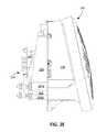
- FIG. 2Eis a partial cutaway front view of the robot of FIG. 2A , with a left portion of the front view showing internal components isolated from the robot and a right portion of the front view showing an exterior of the robot.
- FIG. 3Ais a cross-sectional view of a flexible member through section lines 3 A- 3 A shown in FIG. 1D .
- FIG. 3Bis a cross-sectional view of a flexible member and an interface cable through section lines 3 B- 3 B shown in FIG. 1D .
- FIG. 4is a front view of a flexible member.
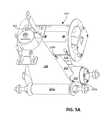
- FIGS. 5A and 5Bare perspective and side views, respectively, of a mast system.
- FIGS. 6A-6Dare perspective, perspective exploded, front cross-sectional, and side cross-sectional views, respectively, of a spool assembly of the mast system of FIG. 3A .
- FIGS. 7A-7Care perspective, perspective exploded views, and front cross-sectional, respectively, of a drive roller assembly of the mast system of FIG. 3A .
- a monitoring systemincludes an autonomous mobile robot 100 including an image capture device 102 such as a camera to capture digital imagery of an environment 10 of the robot 100 .
- the monitoring systemprovides data, e.g., digital imagery data, that enables remote surveillance and monitoring of locations throughout the environment 10 .
- the robot 100operates in an autonomous manner without user intervention by autonomously traversing the environment 10 while capturing imagery using the image capture device 102 .
- the image capture device 102is moved vertically relative to a floor surface 20 to enable the image capture device 102 to capture imagery of the environment 10 at different heights.
- the robot 100monitors a door 30 in the environment 10 by directing its image capture device 102 at the door 30 to capture imagery of the door 30 .
- the robot 100includes a mast system 104 that enables the image capture device 102 to be moved vertically.
- the mast system 104includes a flexible member 106 that supports the image capture device 102 above a body 108 of the robot 100 .
- the flexible member 106is a vertically extendible member that is capable of being retracted into the body 108 or protracted from the body 108 to move the image capture device 102 to different heights.
- FIG. 1Bshows a configuration of the mast system 104 of the robot 100 for positioning the image capture device 102 at a height H 1 above the floor surface 20 as depicted in FIG. 1A .
- the flexible member 106is controllable so that the image capture device 102 moves vertically (from the lower height H 1 to the greater height H 2 as depicted in FIG. 1C .) away from the height H 1 , e.g., toward a height H 2 depicted in FIG. 1C .
- FIG. 1Dshows a configuration of the mast system 104 of the robot 100 in which the image capture device 102 is positioned at a height H 2 above the floor surface 20 as depicted in FIG. 1C . As shown in FIG.
- the flexible member 106is controllable so that the image capture device 102 moves vertically towards the floor surface 20 from the height H 2 , e.g., toward the height H 1 (so that the image capture device 102 is lowered from the greater height H 2 to the lower height H 1 ).
- the flexible member 106can be drawn into or fed out of the robot 100 from a spooled configuration within the body 108 of the robot 100 .
- the flexible member 106can occupy a relatively small amount of space within the body 108 of the robot 100 , thus enabling the robot 100 to have a smaller overall profile.
- FIGS. 2A-2Eillustrate an example of the robot 100 .
- the robot 100includes a drive that is operable to maneuver the robot 100 about a floor surface (e.g., the floor surface 20 shown in FIGS. 1A and 1C ).
- the drive of the robot 100includes any suitable mechanism or system for actively and controllably causing the robot 100 to transit through the environment 10 .
- the driveincludes drive wheels 110 a , 110 b that support the body 108 of the robot 100 above the floor surface and one or more motors 112 (represented by dashed lined boxes to indicate their locations within the body 108 ) engaged to the drive wheels 110 a , 110 b .
- the drive wheels 110 a , 110 bare rotatably driven by the one or more motors 112 .
- the one or more motors 112are controllable by a controller 114 (represented by a dashed line box to indicate its location within the body 108 ) of the robot 100 .
- the one or more motors 112includes two distinct motors, with one motor being operable to control rotation of the drive wheel 110 a , another motor being operable to control rotation of the drive wheel 110 b.
- the robot 100has a substantially trapezoidal profile such that a center of mass of the robot 100 is closer to the floor surface 20 for added stability as the robot 100 transits along the floor surface 20 .
- the body 108houses electromechanical systems of the robot 100 , including the one or more motors 112 , the controller 114 , portions of the mast system 104 , and other systems enabling autonomous function of the robot 100 .
- the electromechanical systemsinclude a power system, a sensor system, or both.
- the power systemincludes a battery and a battery charging system configured to electrically connect the battery to a docking station.
- the robot 100is capable of operating with energy stored on the battery to move about the environment 10 and capture digital imagery and is connectable to the docking station to recharge the battery.
- the sensor systemincludes an image sensor of the image capture device 102 .
- the image capture device 102includes the image sensor, a housing for the image sensor, a lens to transmit received light from the environment 10 to the image sensor, and other components enabling operation of the image sensor for image capture.
- the sensor systemalso includes sensors (e.g., navigation sensors) usable by the controller 114 to navigate about the environment 10 .
- the navigation sensorsgenerate signals for estimating a position of the robot 100 within the environment 10 , for detecting objects and obstacles within the environment 10 , and for generating a robot map, e.g., an occupancy map of the enclosure space 10 .
- These navigation sensorsinclude, for example, dead reckoning sensors, obstacle detection and avoidance (ODOA) sensors, simultaneous localization and mapping (SLAM) sensors, etc.
- the navigation sensorsinclude, in some cases, the image sensor of the image capture device 102 for visual identification of features and landmarks used in calculating robot pose on the robot map.
- the navigation sensorsalternatively or additionally include proximity sensors, contact sensors, motion sensors, cliff sensors, or a combination thereof.
- the robot 100further includes a rear stability wheel 116 , e.g., a caster wheel, that extends rearward from the body 108 and cooperates with the drive wheels 110 a , 110 b to support the body 108 above the floor surface.
- the stability wheel 116is movable relative to the body 108
- the robot 100includes a motor operably connected to the stability wheel 116 to move the stability wheel 116 relative to the body 108 .
- the stability wheel 116is movable into an interior of the robot 100 .
- a footprint of the robot 100 on the floor surfaceis defined by exterior components of the robot 100 , such as the body 108 and the drive wheels 110 a , 110 b .
- the area of the footprintis less than 0.5 square meters, e.g., less than 0.1 square meters, less than 0.3 square meters, less than 0.05 square meters.
- the smaller area footprintcan enable the robot 100 to be easily stored when it is not being operated and to more easily transit between rooms of an environment. If the environment is cluttered, e.g., having many obstacles and having relatively small traversable areas, the smaller area footprint of the robot 100 can enable the robot 100 to maneuver between and around the obstacles without contacting the obstacles.
- the body 108includes an opening 118 through which the image capture device 102 and the flexible member 106 extend from within the body 108 to outside of the body 108 or retract from outside of the body 108 to within the body 108 .
- a distal portion 120 of the flexible member 106e.g., a distal end of the flexible member 106 , is coupled to the image capture device 102 such that movement of the distal portion 120 causes movement of the image capture device 102 .
- the flexible member 106is attached to a housing 122 of the image capture device 102 .
- the housing 122is a rigid structure, e.g., formed from a metal such as aluminum or steel or formed from a rigid polymer such as a polycarbonate, acrylonitrile butadiene styrene, or nylon, that supports the image capture device 102 .
- the distal portion 120 of the flexible member 106is wrapped around an outer surface of a bottom portion 124 of the housing 122 to attach the flexible member 106 to the housing 122 .
- FIG. 2Cillustrates the robot 100 with the image capture device 102 and the flexible member 106 are in fully retracted positions.
- a top surface 119 of the image capture device 102is substantially flush or entirely flush with a top surface 121 of the body 108 .
- the image capture device 102is positioned between 0 and 1 cm from the top surface 121 of the body 108 , e.g., between 0 and 0.3 cm, 0.3 cm and 0.7 cm, or 0.7 cm and 1 cm from the top surface 121 of the body 108 , when the image capture device 102 is in the fully retracted position.
- an image sensor of the image capture device 102is positioned within the body 108 such that the image sensor cannot capture digital imagery of the environment 10 .
- the image capture device 102can be placed into the fully retracted position, for example, to provide privacy for human occupants of the environment 10 .
- the image capture device 102can be placed into the fully retracted position to protect the image capture device 102 as the robot 100 traverses the environment 10 or when the robot 100 is stored.
- the robot 100has a more compact profile when the image capture device 102 is fully retracted, thereby enabling the robot 100 to be more easily stored.
- FIG. 2Dillustrates the robot 100 when the image capture device 102 and the flexible member 106 are in fully protracted positions.
- the flexible member 106 and the image capture device 102are movable along a longitudinal axis A 1 , e.g., a vertical axis extending through the opening 118 from which the flexible member 106 is protracted.
- a maximum height H 3 of the flexible member 106 above the floor surfaceis between 0.5 and 2.5 meters, e.g., between 0.5 and 1.5 meters, 1.0 and 2.0 meters, or 1.5 and 2.5 meters.
- the maximum height H 3 of the flexible member 106corresponds to the maximum height of the image capture device 102 in the fully protracted position.
- the body 108 of the robot 100has a height H 4 above the floor surface between 0.15 and 0.5 meters, e.g., between 0.15 and 0.3 meters, 0.15 and 0.4 meters, or 0.15 and 0.35 meters.
- the height H 4corresponds to the height of the image capture device 102 in the fully retracted position.
- the height H 4 of the body 108is between 10 and 40% of the maximum height H 3 of the flexible member 106 , e.g., between 10 and 30%, 15 and 35%, or 20 and 40% of the maximum height H 3 .
- the mast system 104includes portions housed within the body 108 that cooperate with one another to extend the flexible member 106 from the body 108 or retract the flexible member into the body 108 .
- the mast system 104includes a spool assembly 200 , a drive roller assembly 202 , and one or more compressing rollers 204 a , 204 b (collectively referred to as compressing rollers 204 ).
- the flexible member 106is routed through the body 108 of the robot 100 along an outer surface of the drive roller assembly 202 , along outer surfaces of the one or more compressing rollers 204 , and along an outer surface of the spool assembly 200 .
- an interface cable 138e.g., a ribbon cable as shown in FIG.
- the mast system 104is further described with respect to FIGS. 5A, 5B, 6A-6D, and 7A-7C .
- the mast system 104coils and uncoils the flexible member 106 to retract or protract, respectively, the flexible member 106 .
- the distal portion 120 (shown in FIG. 2D ) of the flexible member 106 and the image capture device 102are retracted into the body 108 as the flexible member 106 is coiled, and are protracted from the body 108 as the flexible member 106 is uncoiled.
- a lengthwise section of the flexible member 106is capable of being coiled within the body 108 when the section of the flexible member 106 is in a flattened configuration. When the lengthwise section of the flexible member 106 is uncoiled, the lengthwise section is transitioned from the flattened configuration to a curled configuration.
- FIG. 3Ashows a cross-section of a lengthwise section of the flexible member 106 along section lines 3 A- 3 A in FIG. 1D according to some implementations.
- the lengthwise section of the flexible member 106is in the flattened configuration.
- the flexible member 106is generally a heterogeneous layered structure, including multiple distinct layers having different material properties.
- the flexible member 106includes an outer layer 128 laminated on an inner layer 130 .
- the outer layer 128is formed of a textile or cloth, such as a nylon, an acrylic, a canvas, or a polyester fabric.
- the outer layer 128is formed of a rubber or rubber-like material such as, for example, neoprene or polychloroprene.
- the inner layer 130is formed of a polymer, such as polycarbonate, polypropylene, or polyethylene.
- the outer layer 128is less rigid than the inner layer 130 .
- the outer layer 128has a thickness T 1 between 0.1 and 1 mm, e.g., between 0.1 and 0.8 mm, 0.2 and 0.9 mm, or 0.3 mm and 1 mm.
- the inner layer 130has a thickness T 2 between 0.1 and 1 mm, e.g., between 0.1 and 0.8 mm, 0.2 and 0.9 mm, or 0.3 mm and 1 mm.
- the overall thickness of the flexible material 106e.g., the sum of the thicknesses T 1 and T 2 , is between 0.2 and 2 mm, e.g., between 0.2 and 1.6 mm, 0.4 and 1.8 mm, or 0.6 mm and 2 mm.
- the thickness T 1 of the outer layer 128is between 30% and 70% of the overall thickness of the flexible member 106 , e.g., between 35% and 65%, 40% and 60%, or 45% and 55% of the overall thickness of the flexible member 106 .
- the thickness T 2 of the inner layer 130is between 30% and 70% of the overall thickness of the flexible member 106 , e.g., between 35% and 65%, 40% and 60%, or 45% and 55% of the overall thickness of the flexible member 106 .
- the section of the flexible member 106is substantially flat in the flattened configuration.
- a flatness of the flexible member 106is between 0.1 and 1 mm, e.g., between 0.1 mm and 0.5 mm or 0.5 mm and 1 mm.
- a first lateral edge 132 a of the outer layer 128e.g., corresponding to a first lateral edge of the flexible member 106
- a second lateral edge 132 b of the outer layer 128e.g., corresponding to a second lateral edge of the flexible member 106 are brought together and affixed or fastened to one another.
- the robot 100includes a fastener for affixing or fastening the first and second lateral edges 132 a , 132 b together when the lengthwise section is curled about the longitudinal axis A 1 .
- the fastenerincludes multiple distinct portions, with one portion being attached to the first lateral edge 132 a and another portion being attached to the second lateral edge 132 b .
- the outer layer 128includes a fastener portion 134 a attached to the first lateral edge 132 a and a fastener portion 134 b attached to the second lateral edge 132 b .
- the fastener portion 134 aextends along a length of the first lateral edge 132 a
- the fastener portion 134 bextends along a length of the second lateral edge 132 b.
- the fastener portions 134 a , 134 bform a zipper mechanism.
- the zipper mechanismcorresponds to a zipper mechanism for connecting garments, fabrics, and other flexible textile materials.
- the zipper mechanismis a standard intermeshed zipper.
- the zipper mechanismincludes interlocking clasps arranged on both of the lateral edges 132 a , 132 b .
- the fastener portion 134 acorresponds to one of the sets of clasps of the zipper mechanism, and the fastener portion 134 b corresponds to the other of the sets of clasps of the zipper mechanism.
- the fastener portions 134 a , 134 bare configured to be interlocked to connect the lateral edges 132 a , 132 b to one another.
- the zipper mechanismcorresponds to a zipper mechanism for connecting plastic materials.
- the zipper mechanismincludes interlocking plastic material for connecting the lateral edges 132 a , 132 b .
- the zipper mechanismincludes a first portion that press-fits into a second portion, the first portion corresponding to one of the fastener portions 134 a , 134 b and the second portion corresponding to the other of the fastener portions 134 a , 134 b .
- the zipper mechanismincludes a ridge (e.g., the fastener portion 134 a ) along one of the lateral edges 132 a , 132 b and a cavity (e.g., the fastener portion 134 b ) along the other of the lateral edges 132 a , 132 b .
- the lateral edges 132 a , 132 bare connected to one another when the cavity receives the ridge and thereby forms a press-fit connection with the ridge.
- the fastener portions 134 a , 134 bare affixed or fastened to one another through a hook-and-loop mechanism, with one of the fastener portions 134 a , 134 b including hook-engageable material and the other of the fastener portions 134 a , 134 b including hooks.
- the fastener portions 134 a , 134 binclude magnetically attractive material. The fastener portions 134 a , 134 b are magnetically attracted to one another and thus join the lateral edges 132 a , 132 b when the fastener portions 134 a , 134 b are brought in close proximity to one another.
- FIG. 3Bshows a cross-section of the flexible member 106 and components enclosed within the flexible member 106 along section lines 3 B- 3 B in FIG. 1D .
- the flexible member 106is in the curled configuration. In the curled configuration, the flexible member 106 is curled around the longitudinal axis A 1 (shown in FIGS. 2C and 2D ) and forms a conduit 136 around a portion the cable 138 (illustrated in FIG. 3B as a cross section of the cable).
- the cable 138provides an interface between the controller 114 and the image capture device 102 .
- the cable 138electrically connects the image capture device 102 to the controller 114 of the robot.
- the cable 138includes a data communication cable such that data indicative of the imagery captured by the image capture device 102 is transmittable to the controller 114 and such that the controller 114 can transmit control signals to operate the image capture device 102 .
- the cable 138further includes a power cable that enables power from a power source of the robot 100 to be delivered to the image capture device 102 . Referring briefly to FIG.
- the cable 138when the image capture device 102 is protracted from the body 108 , the cable 138 extends along at least a length of the protracted section of the flexible member 106 , e.g., the length of the flexible member 106 between the body 108 and the image capture device 102 .
- the cable 138thus provides electrical communication between the image capture device 102 and the controller 114 to enable control of the image capture device 102 as the image capture device 102 is protracted from the body 108 .
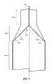
- FIG. 4shows multiple lengthwise sections 140 a , 140 b , 140 c of the flexible member 106 illustrating the transition from the flattened configuration to the curled configuration (and vice versa).
- the lengthwise sections 140 a , 140 b , 140 care positioned along the longitudinal axis A 1 . Only portions of the section 140 a and the section 140 c are visible.
- the section 140 ais arranged in the curled configuration, and the section 140 c is arranged in the flattened configuration.
- the section 140 aextends at least from the distal portion 120 (shown in FIG. 2D ) to proximate the body 108 .
- the section 140 ain the curled configuration, surrounds a portion of the cable 138 extending out of the body 108 , e.g., due to protraction of the image capture device 102 out of the body 108 .
- the fastener portion 134 ais connected to the fastener portion 134 b along the section 140 a to form the conduit 136 .
- Thisthereby connects the first and second lateral edges 132 a , 132 b along the section 140 a as the flexible member 106 is uncoiled.
- the inner layer 130radially supports the outer layer 128 along the section 140 a of the flexible member 106 .
- Thisallows the conduit 136 to be substantially cylindrical along the length of the section, e.g., along the length of the protracted section of the flexible member 106 .
- the conduit 136is substantially cylindrical between the body 108 and the image capture device 102 .
- the flexible member 106is rigid and capable of supporting the image capture device 102 above the body 108 of the robot 100 without collapsing or buckling when the distal portion 120 and the image capture device 102 are moved away from the body along the longitudinal axis A 1 (shown in FIGS. 2C and 2D ).
- the flexible member 106has a buckling strength in the curled configuration higher than a buckling strength in the flattened configuration.
- the wall thickness of the flexible member 106is enlarged without an increase in diameter of the curled formation of the extended flexible member 106 , thereby increasing resistance to buckling under an increased weight of a payload atop the flexible member 106 .
- the payloadis the image capture device 102 , and in other implementations, the payload may be larger, heavier payloads, such as, for example, a wireless router, a router repeater, a wirelessly connected audio media device, or a tablet and/or telephony device.
- the ratio of wall thickness to diameter of the extended, curled flexible member 106may be at or between 1:5 and 1:20, e.g., between 1:7 and 1:18, 1:8 and 1:16 and 1:9 and 1:14.
- the section 140 c of the flexible member 106in the flattened configuration, is flattened so that it can be coiled within the body 108 .
- a lengthwise section of the flexible member 106can be unfurled and transitioned from a curled configuration to a flattened configuration.
- the section 140 b of the flexible member 106is in a transition state between the curled configuration and the flattened configuration in which the section 140 b of the flexible member 106 is curled about the longitudinal axis A 1 but has a smaller curvature than the section 140 a of the flexible member 106 and a larger curvature than the section 140 c of the flexible member 106 .
- the curvature of the section 140 bdecreases from its end connected to the section 140 a to its end connected to the section 140 c .
- the portion of the section 140 b closer to the section 140 ais flatter than the portion of the section 140 b closer to the section 140 c . If the flexible member 106 is uncoiled, at least a portion of the section 140 b is transitioned to the curled configuration. If the flexible member 106 is coiled, at least a portion of the section 140 b is transitioned to the flattened configuration.
- the conduit 136has a diameter D 1 between 0.5 cm and 2.5 cm, e.g., between 0.5 and 2 cm, 0.75 and 1.5 cm, or 1 and 1.25 cm.
- a circumference of the conduit 136is between 3.14 cm and 15.7 cm, e.g., between 4 and 15 cm, 4.5 and 12 cm, or 5 and 10 cm.
- the circumference of the conduit 136is defined by the sum of a width W 1 of the flexible member 106 and the widths of the fastener portions 134 a , 134 b when the fastener portions 134 a , 134 b are connected to one another.
- the width W 1 of the flexible member 106is between 60 and 120 mm, e.g., between 70 and 110 mm, 80 and 100 mm, or 90 and 100 mm.
- FIGS. 5A and 5Billustrate an example of a mechanism of the mast system 104 to coil the flexible member 106 while unfastening the lateral edges 132 a , 132 b of the flexible member 106 or to uncoil the flexible member 106 while fastening the lateral edges 132 a , 132 b of the flexible member 106 .
- the mast system 104includes a fastening and unfastening device 201 positioned below a top surface of the body 108 , e.g., the top surface 121 of the body 108 (shown in FIG. 2C ).
- the device 201is configured to engage the first fastener portion 134 a and the second fastener portion 134 b to zip the fastener portion 134 a , 134 b , thereby connecting the lateral edges 132 a , 132 b of the flexible member 106 .
- the device 201causes, one-by-one, clasps of the first fastener portion 134 a to be engaged to clasps of the second fastener portion 134 b .
- the device 201is a passive device.
- the device 201is stationary and passively engaged to the flexible member 106 as the flexible member 106 moves along the device 201 .
- the first and second fastener portions 134 a , 134 bare the toothed sides of a zipper and the device 201 is a stationary protrusion holding the zipper slider within the body of the robot 100 so that the teeth enmesh and unzip as the flexible member 106 extends and protracts (e.g., furls and unfurls).
- the device 201is an active device.
- the device 201includes an actuator configured to actuate the device 201 .
- the controller 114is configured to control the actuator to engage the first and second fastener portions 134 a , 134 b such that the first and second fastener portions 134 a , 134 b are connected to one another.
- the device 201is configured to connect the first fastener portion 134 a with the second fastener portion 134 b to form the conduit 136 when the distal portion 120 of the flexible member 106 and the image capture device 102 (not shown in FIG. 5A but shown in FIG. 5B ) are extended away from the body 108 .
- the device 201connects the first and second fastener portions 134 a , 134 b at least along a length of the protracted portion of the flexible member 106 .
- the device 201is also configured to disconnect the first fastener portion 134 a with the second fastener portion 134 b when the distal portion 120 and the image capture device 102 are retracted toward the body 108 .
- the device 201disconnects the first and second fastener portions 134 a , 134 b at least along a length of the retracted portion of the flexible member 106 .
- the mast system 104includes a ramp 203 shaped to facilitate transition of a section of the flexible member 106 from a flattened configuration to a curled configuration when the distal portion 120 is extended from the body 108 or from a curled configuration to a flattened configuration when the distal portion 120 is retracted toward the body 108 .
- the ramp 203is a rigid structure that shapes the flexible member 106 as the flexible member 106 passes over the ramp 203 .
- the ramp 203extends away from the drive roller assembly 202 from a first end 205 a proximate the drive roller assembly 202 to a second end 205 b proximate a location on the body 108 through which the flexible member 106 is movable to an exterior of the body 108 , e.g., proximate the opening 118 .
- Tension in the flexible member 106tends to draw the flexible member 106 against the ramp 203 .
- the ramp 203encourages the flexible member 106 to curl into the curled configuration as the flexible member 106 is extended from the body 108 , and encourages the flexible member 106 to flatten into the flattened configuration as the flexible member 106 is retracted into the body 108 .
- the ramp 203is configured to contact the flexible member 106 to inhibit the flexible member 106 from buckling and to control the curvature of the flexible member 106 as the flexible member 106 is moved along the ramp 203 .
- a curvature of the ramp 203increases along a length of the ramp 203 from the first end 205 a toward the second end 205 b of the ramp 203 .
- the ramp 203serves to separate the flexible member 106 from the cable 138 .
- the cable 138is separated from the flexible member 106 at a location above the ramp 203 .
- the flexible member 106follows a path from the opening 118 to the spool assembly 200 distinct from a path of the flexible member 106 from the opening 118 to the spool assembly 200 .
- the path for the flexible member 106extends from the opening 118 (shown in FIG. 2C ), along the ramp 203 , the drive roller assembly 202 , and the compressing rollers 204 , and to the spool assembly 200 .
- the path for the cable 138extends from the opening 118 directly to the spool assembly 200 , e.g., above the ramp 203 .
- the cable 138can be separately spooled from the flexible member 106 on the spool assembly 200 , thereby preventing the cable 138 and the 106 from becoming entangled.
- the robot 100includes a rigid nest 211 positioned within the body 108 of the robot 100 to receive the image capture device 102 .
- the rigid nest 211receives the image capture device 102 when the image capture device 102 is in the fully retracted position.
- the rigid nest 211defines the fully retracted position of the image capture device 102 by inhibiting further retraction of the image capture device 102 .
- the cable 138is coiled when the flexible member 106 is coiled about the spool assembly 200 , and is uncoiled when the flexible member 106 is uncoiled from the spool assembly 200 .
- the flexible member 106 and the cable 138are separately spooled about the spool assembly 200 , with the flexible member 106 being coiled about an outer portion of the spool assembly 200 and the cable 138 being coiled about an inner portion of the spool assembly 200 .
- the flexible member 106is coiled about an outer spool 206
- the cable 138is coiled about an inner spool 208 .
- the inner spool 208is telescoped within the outer spool 206 .
- the inner spool 208 and the outer spool 206are concentric.
- a central axis of the outer spool 206is coincident with a central axis of the inner spool 208 .
- These central axescorrespond to a rotational axis A 2 of the spool assembly 200 .
- An outer surface of the outer spool 206 about which the flexible member 106 is coiledhas a diameter D 2 (shown in FIG. 6D ) between 40 and 80 mm, e.g., between 45 mm and 75 mm, 50 and 70 mm, or 55 and 65 mm.
- An outer surface of the inner spool 208 about which the cable 138 is coiledhas a diameter D 3 (shown in FIG. 6D ) between 5 and 30 mm, e.g., between 5 and 20 mm, 10 and 25 mm, or 15 and 30 mm.
- the diameter D 3is between 10% and 50% of the diameter D 2 , e.g., between 10% and 35%, 15% and 40%, 20% and 45%, or 25% and 50% of the diameter D 1 .
- the cable 138is routed through an opening 210 (shown in FIG. 6A ) along the outer spool 206 .
- the opening 210provides the cable 138 with access to an interior of the spool assembly 200 where the inner spool 208 is located.
- the opening 210is a slit on the outer spool 206 extending parallel to the rotational axis A 2 .
- the cable 138extends through the opening 210 to engage the inner spool 208 .
- the inner spool 208is fixed to the body 108 of the robot 100 .
- the spool assembly 200includes a spring assembly 212 .
- the spring assembly 212includes a spring 216 positioned within a housing 218 fixed to a mounting device 214 fixed to the body 108 (not shown) of the robot 100 .
- the spring 216is a clock spring or other spring that is energized in response to rotation.
- the spring 216has a first end coupled to the housing 218 or the mounting device 214 and a second end coupled to a drive axle 217 .
- the drive axle 217is rotatable relative to the inner spool 208 and is rotationally coupled to the outer spool 206 .
- the spring 216is arranged to bias the drive axle 217 , cause rotation of the drive axle 217 , and thereby cause rotation of the outer spool 206 .
- the spring 216is also configured to be tensioned in response to rotation of the drive axle 217 .
- the drive axle 217has a first end rotatably coupled to the spring assembly 212 and a second end rotatably coupled to the inner spool 208 .
- the outer spool 206is rotationally coupled to the drive axle 217 at a center portion of the drive axle 217 .
- the spring 216is tensioned when the outer spool 206 is rotated in a first direction and is configured to rotate the outer spool 206 in a second direction when the spring 216 is released.
- the outer spool 206rotates relative to the inner spool 208 in the first direction to feed out the flexible member 106 .
- the outer spool 206rotates relative to the inner spool 208 in the second direction to draw in the flexible member 106 and wind the flexible member 106 about the outer spool 206 .
- the cable 138is contained within the outer spool 206 when coiled within the body 108 (not shown).
- the cable 138is fed out of the outer spool 206 through rotation of the outer spool 206 as an inner surface 220 of the outer spool 206 contacts the cable 138 .
- This contactensures that the cable 138 is driven by rotation of the outer spool 206 .
- the cable 138is drawn into the outer spool 206 through rotation of the outer spool 206 and is wound about the inner spool 208 due to contact between the cable 138 and the inner surface 220 of the outer spool 206 .
- the cable 138 and the flexible member 106are attached to the spool assembly 200 such that a tension in the flexible member 106 is greater than a tension in the cable 138 .
- the cable 138is slack while the flexible member 106 is taut.
- the cable 138can be less prone to damage when the flexible member 106 is protracted and retracted.
- the flexible member 106 and the cable 138are coiled about the spool assembly 200 , the flexible member 106 is wound more tightly around the outer spool 206 than the cable 138 is wound about the inner spool 208 .
- the cable 138when coiled about the inner spool 208 , is arranged around the inner spool 208 such that the cable 138 follows a path along the inner surface 220 of the outer spool 206 facing the inner spool 208 . Slack in the cable 138 can cause the cable 138 to be biased radially outward from the inner spool 208 . As a result, the cable 138 contacts the inner surface 220 of the outer spool 206 when the cable 138 is coiled about the inner spool 208 . This contact can provide friction between the outer spool 206 and the cable 138 so that rotation of the outer spool 206 causes the cable 138 to be coiled or uncoiled.
- the drive roller assembly 202includes a drive roller 221 rotatable to coil or uncoil the flexible member 106 and the cable 138 .
- the drive roller assembly 202includes a motor 222 operable to rotate the drive roller 221 .
- the motor 222is positioned within drive roller 221 . This can reduce the amount of space in the body 108 required for housing the drive roller assembly 202 .
- the drive roller assembly 202further includes a motor mount 224 positioned on one end of the drive roller 221 .
- the motor mount 224is configured to mount the motor 222 to the body 108 of the robot 100 .
- the drive roller assembly 202also includes a bearing 226 positioned on the motor mount 224 to allow for rotation between the drive roller 221 and the motor mount 224 .
- a drive coupler 228 of the drive roller assembly 202couples a shaft 230 of the motor 222 to the drive roller 221 .
- the drive coupler 228thus enables rotation of the motor shaft 230 to cause rotation of drive roller 221 .
- the motor 222is operably connected to the controller 114 so that the controller 114 can control rotation of the motor 222 and thereby control a height of the image capture device 102 .
- the controller 114operates the motor 222 to control an amount of the flexible member 106 that is protracted from the body 108 of the robot 100 .
- the protracted amountdefines the height of the image capture device 102 above the floor surface.
- the motor 222is configured to be driven to rotate the motor shaft 230 and hence the drive roller 221 is in a first direction, e.g., clockwise in the perspective as shown in FIG. 5B , to cause the flexible member 106 and the cable 138 to be uncoiled from the spool assembly 200 .
- the compressing rollers 204compress a portion of the flexible member 106 against the drive roller 221 to maintain contact between the flexible member 106 and an outer surface 232 of the drive roller 221 when the drive roller 221 is rotated.
- the compressing rollers 204provide a normal force on the flexible member 106 against the drive roller 221 , thereby providing friction between the flexible member 106 and the drive roller 221 .
- the motor 222is also configured to be driven to rotate the motor shaft 230 and hence the drive roller 221 in a second direction, e.g., counterclockwise in the perspective as shown in FIG. 5B , to cause the flexible member 106 and the cable 138 to be coiled about the spool assembly 200 .
- Rotation of the drive roller 221applies a force to a portion of the flexible member 106 that moves the portion of the flexible member 106 toward the spool assembly 200 .
- the drive roller 221feeds the portion of the flexible member 106 to the spool assembly 200 .
- the spring 216rotates the spool assembly 200 to draw in the portion of the flexible member 106 as the drive roller 221 feeds the portion of the flexible member 106 to the spool assembly 200 .
- the spring 216allows for a non-motorized way of rotating the spool assembly 200 .
- the robot 100can monitor the position of the flexible member 106 during retraction and protraction of the flexible member 106 .
- the robot 100includes a sensor to detect motion of the flexible member 106 as the flexible member 106 is coiled and uncoiled.
- the controller 114is configured to determine a length of an uncoiled portion or a length of a coiled portion of the flexible member 106 based on the motion of the flexible member 106 detected by the sensor.
- an encoder associated with the motor 222measures the amount of the flexible member 106 fed out of or drawn into the spool assembly 200 .
- the sensorincludes an optical sensor 209 (shown in FIG.
- the optical sensor 209is an optical motion sensor that tracks cumulative motions of the flexible member 106 .
- the controller 114is configured to determine the height of the distal portion 120 of the flexible member 106 based on this tracked motion.
- the environment 10includes one or more enclosed spaces such as a set of multiple rooms or spaces defined by a structure or a building, e.g., a home, a residential dwelling, a single family home, a multi-family dwelling, a unit of a duplex, apartment, or condominium, a mobile home, or a commercial living space, an office, a studio, a manufacturing plant, etc.
- enclosed spacessuch as a set of multiple rooms or spaces defined by a structure or a building, e.g., a home, a residential dwelling, a single family home, a multi-family dwelling, a unit of a duplex, apartment, or condominium, a mobile home, or a commercial living space, an office, a studio, a manufacturing plant, etc.
- data indicative of the digital imagery generated by the image capture device 102is transmitted to a remote computing device.
- the remote computing deviceincludes a display to present the digital imagery to a user so that the user can monitor an object captured in the digital imagery.
- data representing the captured images and/or detected conditionsare transmitted to a network, e.g., the Internet.
- the dataare accessible by a user terminal through a portal on the network.
- the user terminalis operable to present views of the enclosure space formed from imagery captured by the robot from multiple locations and directions. The views include views of the enclosure space from multiple vantage points to provide the user with a visual representation of surroundings of the robot within the enclosure space.
- the flexible member 106is described as being movable vertically away from the body 108 of the robot 100 .
- the flexible member 106is movable both vertically and horizontally away from the body 108 of the robot 100 .
- the image capture device 102moves along an axis at a non-perpendicular angle relative to the floor surface 20 .
- the image capture device 102is moved horizontally away from the body 108 of the robot 100 . This type of movement allows the image capture device 102 to be repositioned to capture imagery in areas that the robot 100 cannot reach through movement along the floor surface 20 , e.g., under furniture, around corners, etc.
- the fastener portions 134 a , 134 bare described as being attached to the outer layer 128 .
- the fastener portions 134 a , 134 bare integral to the outer layer 128 .
- the fastener portions 134 a , 134 bare formed from the same material that forms the outer layer 128 .
- the fastener portions 134 a , 134 bcorrespond to, in some cases, plastic features that, when mated with one another, connect lateral ends of the outer layer 128 .
- the flexible member 106includes a single layer configured to be curled about the longitudinal axis and configured to support the image capture device 102 .
- the single layerincludes, in some cases, integral fastener portions 134 a , 134 b.
- the robot 100includes a data communication cable separate from a power delivery cable.
- the data communication cable and the power delivery cableare spooled about a single spool, e.g., the inner spool 208 .
- the data communication cable and the power delivery cableare each spooled about its own distinct spool, e.g., positioned within the outer spool 206 .
- the image capture device 102is described to be supported by the distal portion 120 of the flexible member 106
- another sensoris supported by the distal portion 120 .
- the sensorprovides a measurement that varies with location within the environment 10 , e.g., varying with height and floor surface location.
- the sensorincludes one or more of a temperature sensor that measures a temperature within the environment 10 , a moisture sensor that measures a moisture content of the environment 10 , a pressure sensor such a barometer that measures a barometric pressure of the environment 10 , an air quality sensor that measures an air quality of the environment 10 , or a light sensor to detect ambient light in the environment 10 .
- the distal portion 120 of the flexible member 106includes a mechanical end effector, such as a gripper, a suction cup, a rotatable member, or other end effector.
- the end effectoris controllable by the controller 114 to perform an operation in the environment 10 in which the end effector interacts with an object in the environment 10 .
- the mechanical end effectoris a gripper
- the end effectoris operable to grasp an object
- the robot 100is movable to reposition the grasped object in the environment 10 .
- cable 138is described as an electrical cable, in some implementations, the cable 138 enables transmission of data or power through another medium.
- cable 138can be an optical cable that enables transmission of an optical signal indicative of data to be transmitted from the image capture device 102 to the controller 114 .
- the image capture device 102is electrically isolated from the controller 114 , and the cable 138 is absent.
- the image capture device 102is powered by a battery supported by the distal portion 120 of the flexible member 106 and communicates data wirelessly to the controller 114 .
- the image capture device 102is operated by the controller 114 by receiving wireless command signals from the controller 114 .
- only the flexible member 106is spooled about the spool assembly 200 .
- Such examplescan simplify the mast system 104 , as only a single member, e.g., the flexible member 106 , rather than multiple members, e.g., the flexible member 106 and the cable 138 , is coiled and uncoiled to move the image capture device 102 vertically.
- compressing rollers 204 a , 204 bare shown, in some implementations, a single compressing roller is present.
- the compressing roller 204 a proximate the ramp 203is present while the compressing roller 204 b is absent. This can further reduce the amount of space occupied by the mast system 104 .
- two or more compressing rollersare used to compress the flexible member 106 against the drive roller assembly 202 .
- the mast system 104includes two or more distinct spool assemblies.
- the spool 208is separate from the spool 206 and positioned outside of the spool 206 .
- Corresponding springse.g., similar to the spring 216 , are coupled to the spools 206 , 208 .
- the cable 138 and the flexible member 106are described as being coiled about spools within the robot 100 , in some implementations, the cable 138 or the flexible member 106 is stored in another configuration within the robot 100 .
- the flexible member 106 or the cable 138is folded within a confined space in the body 108 of the robot 100 .
- the robot 100includes another motor distinct from the motor 222 .
- This other motoris configured to drive the outer spool 206 of the spool assembly 200 so that the outer spool 206 is rotated during retraction of the flexible member 106 .
- the motor 222is connected through a transmission system to the spool assembly 200 . In this regard, the motor 222 , when driven, causes rotation of the both the drive roller 202 and the outer spool 206 .
- the mast system 104is usable with other devices in which a portion of the device is protractible or retractable.
- the mast system 104is part of a stationary support system for an image capture device, such as a tripod or monopod.
- the mast system 104is part of a stationary image capture system mounted to the environment 10 , e.g., for a home security system or commercial security system.
- the payloadis a device other than an image capture device.
- the mast system 104may raise and lower devices during use and non-use states.
- the mast system 104may be part of a mobile or stationary apparatus or system that raises and lowers a wireless router or router repeater dynamically to improve signal strength within an environment when and where weaknesses are detected.
- the mast system 104may be a stand-alone system for providing a retractable, protractable support mast for a payload.
- the robots described hereincan be controlled, at least in part, using one or more computer program products, e.g., one or more computer programs tangibly embodied in one or more information carriers, such as one or more non-transitory machine-readable media, for execution by, or to control the operation of, one or more data processing apparatus, e.g., a programmable processor, a computer, multiple computers, and/or programmable logic components.
- one or more computer program productse.g., one or more computer programs tangibly embodied in one or more information carriers, such as one or more non-transitory machine-readable media, for execution by, or to control the operation of, one or more data processing apparatus, e.g., a programmable processor, a computer, multiple computers, and/or programmable logic components.
- Operations associated with controlling the robots described hereincan be performed by one or more programmable processors executing one or more computer programs to perform the functions described herein.
- a computer programcan be written in any form of programming language, including compiled or interpreted languages, and it can be deployed in any form, including as a stand-alone program or as a module, component, subroutine, or other unit suitable for use in a computing environment.
- Control over all or part of the robots described hereincan be implemented using special purpose logic circuitry, e.g., an FPGA (field programmable gate array) and/or an ASIC (application-specific integrated circuit).
- FPGAfield programmable gate array
- ASICapplication-specific integrated circuit
- the controllers described hereincan include one or more processors.
- processors suitable for the execution of a computer programinclude, by way of example, both general and special purpose microprocessors, and any one or more processors of any kind of digital computer.
- a processorwill receive instructions and data from a read-only storage area or a random access storage area or both.
- Elements of a computerinclude one or more processors for executing instructions and one or more storage area devices for storing instructions and data.
- a computerwill also include, or be operatively coupled to receive data from, or transfer data to, or both, one or more machine-readable storage media, such as mass PCBs for storing data, e.g., magnetic, magneto-optical disks, or optical disks.
- Machine-readable storage media suitable for embodying computer program instructions and datainclude all forms of non-volatile storage area, including by way of example, semiconductor storage area devices, e.g., EPROM, EEPROM, and flash storage area devices; magnetic disks, e.g., internal hard disks or removable disks; magneto-optical disks; and CD-ROM and DVD-ROM disks.
- semiconductor storage area devicese.g., EPROM, EEPROM, and flash storage area devices
- magnetic diskse.g., internal hard disks or removable disks
- magneto-optical diskse.g., CD-ROM and DVD-ROM disks.
Landscapes
- Engineering & Computer Science (AREA)
- Mechanical Engineering (AREA)
- General Engineering & Computer Science (AREA)
- Robotics (AREA)
- Architecture (AREA)
- Physics & Mathematics (AREA)
- General Physics & Mathematics (AREA)
- Multimedia (AREA)
- Civil Engineering (AREA)
- Structural Engineering (AREA)
- Manipulator (AREA)
Abstract
Description
Claims (25)
Priority Applications (1)
| Application Number | Priority Date | Filing Date | Title |
|---|---|---|---|
| US16/106,628US10458593B2 (en) | 2017-06-12 | 2018-08-21 | Mast systems for autonomous mobile robots |
Applications Claiming Priority (2)
| Application Number | Priority Date | Filing Date | Title |
|---|---|---|---|
| US15/620,658US10100968B1 (en) | 2017-06-12 | 2017-06-12 | Mast systems for autonomous mobile robots |
| US16/106,628US10458593B2 (en) | 2017-06-12 | 2018-08-21 | Mast systems for autonomous mobile robots |
Related Parent Applications (1)
| Application Number | Title | Priority Date | Filing Date |
|---|---|---|---|
| US15/620,658ContinuationUS10100968B1 (en) | 2017-06-12 | 2017-06-12 | Mast systems for autonomous mobile robots |
Publications (2)
| Publication Number | Publication Date |
|---|---|
| US20190032842A1 US20190032842A1 (en) | 2019-01-31 |
| US10458593B2true US10458593B2 (en) | 2019-10-29 |
Family
ID=63761246
Family Applications (2)
| Application Number | Title | Priority Date | Filing Date |
|---|---|---|---|
| US15/620,658ActiveUS10100968B1 (en) | 2017-06-12 | 2017-06-12 | Mast systems for autonomous mobile robots |
| US16/106,628ActiveUS10458593B2 (en) | 2017-06-12 | 2018-08-21 | Mast systems for autonomous mobile robots |
Family Applications Before (1)
| Application Number | Title | Priority Date | Filing Date |
|---|---|---|---|
| US15/620,658ActiveUS10100968B1 (en) | 2017-06-12 | 2017-06-12 | Mast systems for autonomous mobile robots |
Country Status (2)
| Country | Link |
|---|---|
| US (2) | US10100968B1 (en) |
| WO (1) | WO2018231271A1 (en) |
Cited By (1)
| Publication number | Priority date | Publication date | Assignee | Title |
|---|---|---|---|---|
| US20200180142A1 (en)* | 2018-12-11 | 2020-06-11 | Irobot Corporation | Mast Systems for Autonomous Mobile Robots |
Families Citing this family (13)
| Publication number | Priority date | Publication date | Assignee | Title |
|---|---|---|---|---|
| WO2018157061A1 (en)* | 2017-02-27 | 2018-08-30 | River Front Services, Inc. | Structural tape deployment apparatus |
| US10100968B1 (en)* | 2017-06-12 | 2018-10-16 | Irobot Corporation | Mast systems for autonomous mobile robots |
| US10859368B2 (en)* | 2018-11-14 | 2020-12-08 | Wilkinson Egwu | Smart lawn sensor adapted to monitor lawn height and system of providing lawn care |
| CN109571405B (en)* | 2018-12-13 | 2021-06-18 | 杭州申昊科技股份有限公司 | An intelligent inspection robot for underground cable network management |
| US11130235B2 (en) | 2019-02-15 | 2021-09-28 | Boston Dynamics, Inc. | Work mode and travel mode for mobile robots |
| US11358845B1 (en)* | 2019-03-15 | 2022-06-14 | Amazon Technologies, Inc. | Electromagnetic noise cancellation apparatus for cable deployed at varying length |
| US11249482B2 (en) | 2019-08-09 | 2022-02-15 | Irobot Corporation | Mapping for autonomous mobile robots |
| US11327483B2 (en) | 2019-09-30 | 2022-05-10 | Irobot Corporation | Image capture devices for autonomous mobile robots and related systems and methods |
| FR3103128B1 (en)* | 2019-11-19 | 2022-07-29 | Meropy | Autonomous robot |
| US11571813B2 (en) | 2020-02-28 | 2023-02-07 | Irobot Corporation | Systems and methods for managing a semantic map in a mobile robot |
| CN111396727B (en)* | 2020-04-24 | 2021-05-28 | 江苏食品药品职业技术学院 | A sliding multi-angle adjustment video camera for computer |
| CN113927624B (en)* | 2021-10-18 | 2023-04-07 | 九江学院 | Extendable quadruped robot based on rollable thin-walled tube |
| CN117958649A (en)* | 2023-03-27 | 2024-05-03 | 北京石头创新科技有限公司 | Self-contained equipment and control method thereof, storage medium, and computer equipment |
Citations (149)
| Publication number | Priority date | Publication date | Assignee | Title |
|---|---|---|---|---|
| US2967465A (en)* | 1958-01-20 | 1961-01-10 | Nat Paper Can & Tube Company | Continuous spool assembly machine |
| US3144215A (en)* | 1961-01-19 | 1964-08-11 | Dehavilland Aircraft Canada | Coilable extensible apparatus |
| US3144104A (en)* | 1961-08-03 | 1964-08-11 | Dehavilland Aircraft Canada | Coilable tube device |
| US3252173A (en) | 1963-12-11 | 1966-05-24 | Eli I Robinsky | Continuously extensible and roll-up structure |
| US3503164A (en) | 1968-01-03 | 1970-03-31 | Fairchild Hiller Corp | Tubular extendable structure |
| US3696568A (en) | 1970-10-28 | 1972-10-10 | Fairchild Hiller Corp | Collapsible, extendible double tubular structure |
| US3832240A (en)* | 1970-08-01 | 1974-08-27 | Tokyo Shibaura Electric Co | Production of extendible rods |
| US4096459A (en) | 1973-09-24 | 1978-06-20 | Herman Lowenhar | Two wire transmission line using tubular extendible structures |
| US4777416A (en) | 1986-05-16 | 1988-10-11 | Denning Mobile Robotics, Inc. | Recharge docking system for mobile robot |
| US4857912A (en) | 1988-07-27 | 1989-08-15 | The United States Of America As Represented By The Secretary Of The Navy | Intelligent security assessment system |
| US5084828A (en) | 1989-09-29 | 1992-01-28 | Healthtech Services Corp. | Interactive medication delivery system |
| US5199931A (en)* | 1991-11-27 | 1993-04-06 | Fitness Master, Inc. | Exercise machine for simulating stair climbing |
| US5201814A (en) | 1992-01-23 | 1993-04-13 | Conoco Inc. | Breakaway coupling device |
| US5448696A (en) | 1990-11-30 | 1995-09-05 | Hitachi, Ltd. | Map information system capable of displaying layout information |
| US5732401A (en) | 1996-03-29 | 1998-03-24 | Intellitecs International Ltd. | Activity based cost tracking systems |
| US5793900A (en) | 1995-12-29 | 1998-08-11 | Stanford University | Generating categorical depth maps using passive defocus sensing |
| US5802494A (en) | 1990-07-13 | 1998-09-01 | Kabushiki Kaisha Toshiba | Patient monitoring system |
| US5808663A (en) | 1997-01-21 | 1998-09-15 | Dell Computer Corporation | Multimedia carousel for video conferencing and multimedia presentation applications |
| US6208379B1 (en) | 1996-02-20 | 2001-03-27 | Canon Kabushiki Kaisha | Camera display control and monitoring system |
| US6217975B1 (en) | 1996-03-25 | 2001-04-17 | Rolatube Technology Limited | Extendible member |
| US6256938B1 (en) | 1987-04-30 | 2001-07-10 | Rolatube Technology Limited | Elongate hollow element |
| US6272237B1 (en) | 1995-10-11 | 2001-08-07 | Fujitsu Limited | Image processing apparatus |
| US20010020837A1 (en) | 1999-12-28 | 2001-09-13 | Junichi Yamashita | Information processing device, information processing method and storage medium |
| US6292713B1 (en) | 1999-05-20 | 2001-09-18 | Compaq Computer Corporation | Robotic telepresence system |
| US20010024233A1 (en) | 1996-10-15 | 2001-09-27 | Shinya Urisaka | Camera control system, camera server, camera client, control method, and storage medium |
| US20010037163A1 (en) | 2000-05-01 | 2001-11-01 | Irobot Corporation | Method and system for remote control of mobile robot |
| US20020016649A1 (en) | 2000-01-24 | 2002-02-07 | Jones Joseph L. | Robot obstacle detection system |
| JP2002046088A (en) | 2000-08-03 | 2002-02-12 | Matsushita Electric Ind Co Ltd | Robot device |
| US6389329B1 (en) | 1997-11-27 | 2002-05-14 | Andre Colens | Mobile robots and their control system |
| US6415203B1 (en) | 1999-05-10 | 2002-07-02 | Sony Corporation | Toboy device and method for controlling the same |
| US20020097322A1 (en) | 2000-11-29 | 2002-07-25 | Monroe David A. | Multiple video display configurations and remote control of multiple video signals transmitted to a monitoring station over a network |
| US20020103576A1 (en) | 1999-05-10 | 2002-08-01 | Sony Corporation | Robot and its control method |
| US20020120364A1 (en) | 1997-11-27 | 2002-08-29 | Andre Colens | Mobile robots and their control system |
| US20020128746A1 (en) | 2001-02-27 | 2002-09-12 | International Business Machines Corporation | Apparatus, system and method for a remotely monitored and operated avatar |
| US6454708B1 (en) | 1999-04-15 | 2002-09-24 | Nexan Limited | Portable remote patient telemonitoring system using a memory card or smart card |
| US20020165790A1 (en) | 2001-05-04 | 2002-11-07 | Allen Bancroft | Methods for facilitating a retail environment |
| US20020199007A1 (en) | 2001-06-12 | 2002-12-26 | Tom Clayton | Virtual private network software system |
| US6509926B1 (en) | 2000-02-17 | 2003-01-21 | Sensormatic Electronics Corporation | Surveillance apparatus for camera surveillance system |
| US20030023348A1 (en) | 1999-01-20 | 2003-01-30 | Sony Corporation | Robot apparatus and motion control method |
| US20030025472A1 (en) | 2001-06-12 | 2003-02-06 | Jones Joseph L. | Method and system for multi-mode coverage for an autonomous robot |
| US20030037250A1 (en) | 2001-06-29 | 2003-02-20 | Doodlebug Online, Inc. | System and method for securely accessing data on content servers using dual encrypted paths from a central authorization host |
| US20030045203A1 (en) | 1999-11-30 | 2003-03-06 | Kohtaro Sabe | Robot apparatus, control method thereof, and method for judging character of robot apparatus |
| US20030060930A1 (en) | 2000-10-13 | 2003-03-27 | Masahiro Fujita | Robot device and behavior control method for robot device |
| US6542788B2 (en) | 1999-12-31 | 2003-04-01 | Sony Corporation | Robot apparatus capable of selecting transmission destination, and control method therefor |
| US20030078696A1 (en) | 1999-10-29 | 2003-04-24 | Sony Corporation | Robot system, robot apparatus and cover for robot apparatus |
| US20030109960A1 (en) | 2000-07-25 | 2003-06-12 | Illah Nourbakhsh | Socially Interactive Autonomous Robot |
| US20030137268A1 (en) | 1999-11-19 | 2003-07-24 | Regents Of The University Of Minnesota | Miniature robotic vehicles and methods of controlling same |
| US6602574B1 (en) | 1998-06-04 | 2003-08-05 | Rolatube Technology Limited | Extendable, rollable member |
| US20030151658A1 (en) | 2002-02-11 | 2003-08-14 | Telbotics Inc. | Video conferencing apparatus |
| US20030167403A1 (en) | 1999-03-02 | 2003-09-04 | Mccurley Kevin Snow | Secure user-level tunnels on the internet |
| US20030182117A1 (en) | 2002-01-31 | 2003-09-25 | Sanyo Electric Co., Ltd. | Information processing method, information processing system, information processing apparatus, health care terminal apparatus, and recording medium |
| US20030185556A1 (en) | 2002-03-28 | 2003-10-02 | Pelco | Retractable camera mounting mechanism |
| US6658325B2 (en) | 2001-01-16 | 2003-12-02 | Stephen Eliot Zweig | Mobile robotic with web server and digital radio links |
| US20030229474A1 (en) | 2002-03-29 | 2003-12-11 | Kaoru Suzuki | Monitoring apparatus |
| US20040019406A1 (en) | 2002-07-25 | 2004-01-29 | Yulun Wang | Medical tele-robotic system |
| US20040020000A1 (en) | 2000-01-24 | 2004-02-05 | Jones Joseph L. | Robot obstacle detection system |
| US6690134B1 (en) | 2001-01-24 | 2004-02-10 | Irobot Corporation | Method and system for robot localization and confinement |
| US20040049877A1 (en) | 2002-01-03 | 2004-03-18 | Jones Joseph L. | Autonomous floor-cleaning robot |
| US20040073368A1 (en) | 2002-05-10 | 2004-04-15 | Hector Gonzalez-Banos | Real-time target tracking of an unpredictable target amid unknown obstacles |
| US20040078219A1 (en) | 2001-12-04 | 2004-04-22 | Kimberly-Clark Worldwide, Inc. | Healthcare networks with biosensors |
| US20040089090A1 (en) | 2002-03-14 | 2004-05-13 | Kabushiki Kaisha Toshiba | Robot system |
| US20040093650A1 (en) | 2000-12-04 | 2004-05-13 | Martins Goesta | Robot system |
| US20040102166A1 (en) | 2002-11-26 | 2004-05-27 | Ge Medical Systems Information Technologies, Inc. | Computer-equipped mobility device for connecting to a network |
| US20040111273A1 (en) | 2002-09-24 | 2004-06-10 | Yoshiaki Sakagami | Receptionist robot system |
| US20040117063A1 (en) | 2001-10-22 | 2004-06-17 | Kohtaro Sabe | Robot apparatus and control method thereof |
| US20040113777A1 (en) | 2002-11-29 | 2004-06-17 | Kabushiki Kaisha Toshiba | Security system and moving robot |
| US20040137911A1 (en) | 2002-08-06 | 2004-07-15 | Richard Hull | Method and apparatus for providing information about a real-world space |
| US20040174129A1 (en) | 2003-03-06 | 2004-09-09 | Yulun Wang | Medical tele-robotic system with a head worn device |
| US20040187457A1 (en) | 2001-05-28 | 2004-09-30 | Andre Colens | Robotic lawnmower |
| US20040202351A1 (en)* | 2003-01-11 | 2004-10-14 | Samsung Electronics Co., Ltd. | Mobile robot, and system and method for autnomous navigation of the same |
| US20040210347A1 (en) | 2002-05-20 | 2004-10-21 | Tsutomu Sawada | Robot device and robot control method |
| US20050009469A1 (en) | 2002-12-20 | 2005-01-13 | Sakari Kotola | Client software download in bluetooth device bonding |
| US20050026631A1 (en) | 2003-07-31 | 2005-02-03 | Hewlett-Packard Development Company, L.P. | Method and apparatus for providing information about a real-world space |
| US20050035862A1 (en) | 2001-05-08 | 2005-02-17 | Wildman Timothy D. | Article locating and tracking apparatus and method |
| US20050046373A1 (en) | 2001-11-03 | 2005-03-03 | Aldred Micheal David | Autonomous machine |
| US20050071047A1 (en) | 2002-05-31 | 2005-03-31 | Fujitsu Limited | Remote-controlled robot and robot self-position identification method |
| US20050091684A1 (en)* | 2003-09-29 | 2005-04-28 | Shunichi Kawabata | Robot apparatus for supporting user's actions |
| US20050125098A1 (en) | 2003-12-09 | 2005-06-09 | Yulun Wang | Protocol for a remotely controlled videoconferencing robot |
| EP1548532A1 (en) | 2002-10-01 | 2005-06-29 | Fujitsu Limited | Robot |
| US6914622B1 (en) | 1997-05-07 | 2005-07-05 | Telbotics Inc. | Teleconferencing robot with swiveling video monitor |
| US20050156562A1 (en) | 2004-01-21 | 2005-07-21 | Irobot Corporation | Autonomous robot auto-docking and energy management systems and methods |
| US20050171636A1 (en) | 2004-01-30 | 2005-08-04 | Funai Electric Co., Ltd. | Autonomous mobile robot cleaner system |
| US20050197739A1 (en) | 2004-01-16 | 2005-09-08 | Kuniaki Noda | Behavior controlling system and behavior controlling method for robot |
| US20050204717A1 (en) | 1999-06-17 | 2005-09-22 | Andre Colens | Device for automatically picking up objects |
| US20050216124A1 (en) | 2004-02-26 | 2005-09-29 | Kabushiki Kaisha Toshiba | Mobile robot for monitoring a subject |
| US20050216126A1 (en)* | 2004-03-27 | 2005-09-29 | Vision Robotics Corporation | Autonomous personal service robot |
| US20050222711A1 (en) | 2004-04-01 | 2005-10-06 | Kabushiki Kaisha Toshiba | Robot and a robot control method |
| US20050231357A1 (en) | 2002-04-30 | 2005-10-20 | Kenji Kanayama | Imaging apparatus, imaging system, imaging apparatus control method and control program, and recording medium in which the same program has been recorded |
| US20050234729A1 (en) | 2002-06-05 | 2005-10-20 | Koninkliijke Phillips Electronic N.V. | Mobile unit and method of controlling a mobile unit |
| US20050251292A1 (en)* | 2000-01-24 | 2005-11-10 | Irobot Corporation | Obstacle following sensor scheme for a mobile robot |
| US6980956B1 (en) | 1999-01-07 | 2005-12-27 | Sony Corporation | Machine apparatus and its driving method, and recorded medium |
| US20060005254A1 (en) | 2004-06-09 | 2006-01-05 | Ross Alan D | Integration of policy compliance enforcement and device authentication |
| US20060006316A1 (en) | 2004-07-09 | 2006-01-12 | Funai Electric Co., Ltd. | Self-running robot |
| US20060041333A1 (en) | 2004-05-17 | 2006-02-23 | Takashi Anezaki | Robot |
| US20060047803A1 (en) | 2004-06-30 | 2006-03-02 | Nokia Inc. | Method and system for dynamic device address management |
| US20060052676A1 (en) | 2004-09-07 | 2006-03-09 | Yulun Wang | Tele-presence system that allows for remote monitoring/observation and review of a patient and their medical records |
| US20060082642A1 (en) | 2002-07-25 | 2006-04-20 | Yulun Wang | Tele-robotic videoconferencing in a corporate environment |
| US20060091297A1 (en) | 2004-10-29 | 2006-05-04 | Anderson Noel W | Method and system for obstacle detection |
| US20060129848A1 (en) | 2004-04-08 | 2006-06-15 | Texas Instruments Incorporated | Methods, apparatus, and systems for securing SIM (subscriber identity module) personalization and other data on a first processor and secure communication of the SIM data to a second processor |
| US20060195226A1 (en) | 2003-08-07 | 2006-08-31 | Matsushita Electric Industrial Co., Ltd. | Mobile robot system and program for controlling the same |
| US20060217837A1 (en) | 2005-03-23 | 2006-09-28 | Kabushiki Kaisha Toshiba | Robot device, movement method of robot device, and program |
| US20060259193A1 (en) | 2005-05-12 | 2006-11-16 | Yulun Wang | Telerobotic system with a dual application screen presentation |
| US20060261207A1 (en)* | 2005-04-19 | 2006-11-23 | Woodruff Christopher D | Apparatus and methods for providing a retractable mast |
| US20070008918A1 (en) | 2005-07-08 | 2007-01-11 | Meshnetworks, Inc. | Application layer presentation of routing and link quality data adapted for use in controlling movement of moveable devices |
| US20070027579A1 (en)* | 2005-06-13 | 2007-02-01 | Kabushiki Kaisha Toshiba | Mobile robot and a mobile robot control method |
| US20070043459A1 (en) | 1999-12-15 | 2007-02-22 | Tangis Corporation | Storing and recalling information to augment human memories |
| US20070046237A1 (en)* | 2005-04-25 | 2007-03-01 | Sridhar Lakshmanan | Miniature surveillance robot |
| US20070055116A1 (en) | 1998-09-18 | 2007-03-08 | Clark Richard A | Mobile clinical workstation |
| US20070061041A1 (en)* | 2003-09-02 | 2007-03-15 | Zweig Stephen E | Mobile robot with wireless location sensing apparatus |
| US20070060105A1 (en) | 2005-08-31 | 2007-03-15 | Puneet Batta | System and method for optimizing a wireless connection between wireless devices |
| US20070064092A1 (en) | 2005-09-09 | 2007-03-22 | Sandbeg Roy B | Mobile video teleconferencing system and control method |
| US7199817B2 (en) | 2000-07-26 | 2007-04-03 | Smiths Detection Inc. | Methods and systems for networked camera control |
| US20070198130A1 (en)* | 2006-02-22 | 2007-08-23 | Yulun Wang | Graphical interface for a remote presence system |
| US7289881B2 (en) | 2001-08-07 | 2007-10-30 | Omron Corporation | Information collection apparatus, information collection method, information collection program, recording medium containing information collection program, and information collection system |
| US20070266508A1 (en)* | 2002-01-03 | 2007-11-22 | Irobot Corporation | Autonomous Floor Cleaning Robot |
| US7340100B2 (en) | 2002-08-09 | 2008-03-04 | Honda Giken Kogyo Kabushiki Kaisha | Posture recognition apparatus and autonomous robot |
| US20080055409A1 (en) | 2004-07-23 | 2008-03-06 | Vicon Industries Inc. | Surveillance Camera System |
| US20080140255A1 (en)* | 2005-02-18 | 2008-06-12 | Irobot Corporation | Autonomous surface cleaning robot for wet and dry cleaning |
| US7389156B2 (en) | 2005-02-18 | 2008-06-17 | Irobot Corporation | Autonomous surface cleaning robot for wet and dry cleaning |
| US7388981B2 (en) | 2003-02-27 | 2008-06-17 | Hewlett-Packard Development Company, L.P. | Telepresence system with automatic preservation of user head size |
| US7388343B2 (en)* | 2001-06-12 | 2008-06-17 | Irobot Corporation | Method and system for multi-mode coverage for an autonomous robot |
| US7388879B2 (en) | 2000-08-28 | 2008-06-17 | Sony Corporation | Communication device and communication method network system and robot apparatus |
| US20080167542A1 (en)* | 2007-01-05 | 2008-07-10 | Lampropoulos Fred P | Measuring and testing device for retractable medical devices |
| US20080215185A1 (en)* | 2006-11-13 | 2008-09-04 | Jacobsen Stephen C | Unmanned ground robotic vehicle having an alternatively extendible and retractable sensing appendage |
| US7467026B2 (en) | 2003-09-22 | 2008-12-16 | Honda Motor Co. Ltd. | Autonomously moving robot management system |
| US7515992B2 (en) | 2004-01-06 | 2009-04-07 | Sony Corporation | Robot apparatus and emotion representing method therefor |
| US7551980B2 (en) | 2003-04-01 | 2009-06-23 | Honda Motor Co., Ltd. | Apparatus, process, and program for controlling movable robot control |
| US7593546B2 (en) | 2003-03-11 | 2009-09-22 | Hewlett-Packard Development Company, L.P. | Telepresence system with simultaneous automatic preservation of user height, perspective, and vertical gaze |
| US20090249222A1 (en) | 2008-03-25 | 2009-10-01 | Square Products Corporation | System and method for simultaneous media presentation |
| US7624438B2 (en) | 2003-08-20 | 2009-11-24 | Eric White | System and method for providing a secure connection between networked computers |
| US7631834B1 (en) | 2006-02-24 | 2009-12-15 | Stealth Robotics, Llc | Aerial robot with dispensable conductive filament |
| US7702420B2 (en) | 2004-07-07 | 2010-04-20 | Panasonic Corporation | Method for making mobile unit accompany objective person |
| US7706917B1 (en) | 2004-07-07 | 2010-04-27 | Irobot Corporation | Celestial navigation system for an autonomous robot |
| US20100277584A1 (en)* | 2007-02-12 | 2010-11-04 | Price Larry J | Systems and Methods for Video Surveillance |
| US20110012003A1 (en)* | 2005-04-19 | 2011-01-20 | Geo Systems, Inc. | Apparatus and methods for providing a retractible mast |
| US8077963B2 (en) | 2004-07-13 | 2011-12-13 | Yulun Wang | Mobile robot with a head-based movement mapping scheme |
| US20120159597A1 (en)* | 1997-07-01 | 2012-06-21 | Thomas C Douglass | Methods for remote monitoring and control of security devices over a computer network |
| US20120173018A1 (en)* | 2010-12-30 | 2012-07-05 | Irobot Corporation | Mobile Human Interface Robot |
| US20130117867A1 (en)* | 2011-11-06 | 2013-05-09 | Hei Tao Fung | Theft Prevention for Networked Robot |
| US8515577B2 (en) | 2002-07-25 | 2013-08-20 | Yulun Wang | Medical tele-robotic system with a master remote station with an arbitrator |
| US20140009561A1 (en)* | 2010-11-12 | 2014-01-09 | Crosswing Inc. | Customizable robotic system |
| US20140048672A1 (en)* | 2005-04-19 | 2014-02-20 | Geo Systems, Inc. | Apparatus and methods for providing a retractable mast |
| US20140122116A1 (en) | 2005-07-06 | 2014-05-01 | Alan H. Smythe | System and method for providing audio data to assist in electronic medical records management |
| US20140230949A1 (en)* | 2011-06-09 | 2014-08-21 | Rtl Materials Ltd | Coilable extendible member and methods |
| US8863369B2 (en) | 2011-09-13 | 2014-10-21 | Composite Technology Development, Inc. | Slit tube locking longeron |
| US9198728B2 (en) | 2005-09-30 | 2015-12-01 | Intouch Technologies, Inc. | Multi-camera mobile teleconferencing platform |
| US20160010333A1 (en)* | 2013-02-15 | 2016-01-14 | Tendeg Llc | Collapsible Roll-Out Truss |
| US9376600B2 (en) | 2008-06-27 | 2016-06-28 | Liberman Disbributing and Manufacturing Co. | Extendable self-supporting material |
| US10100968B1 (en)* | 2017-06-12 | 2018-10-16 | Irobot Corporation | Mast systems for autonomous mobile robots |
- 2017
- 2017-06-12USUS15/620,658patent/US10100968B1/enactiveActive
- 2017-10-30WOPCT/US2017/059086patent/WO2018231271A1/ennot_activeCeased
- 2018
- 2018-08-21USUS16/106,628patent/US10458593B2/enactiveActive
Patent Citations (182)
| Publication number | Priority date | Publication date | Assignee | Title |
|---|---|---|---|---|
| US2967465A (en)* | 1958-01-20 | 1961-01-10 | Nat Paper Can & Tube Company | Continuous spool assembly machine |
| US3144215A (en)* | 1961-01-19 | 1964-08-11 | Dehavilland Aircraft Canada | Coilable extensible apparatus |
| US3144104A (en)* | 1961-08-03 | 1964-08-11 | Dehavilland Aircraft Canada | Coilable tube device |
| US3252173A (en) | 1963-12-11 | 1966-05-24 | Eli I Robinsky | Continuously extensible and roll-up structure |
| US3503164A (en) | 1968-01-03 | 1970-03-31 | Fairchild Hiller Corp | Tubular extendable structure |
| US3832240A (en)* | 1970-08-01 | 1974-08-27 | Tokyo Shibaura Electric Co | Production of extendible rods |
| US3696568A (en) | 1970-10-28 | 1972-10-10 | Fairchild Hiller Corp | Collapsible, extendible double tubular structure |
| US4096459A (en) | 1973-09-24 | 1978-06-20 | Herman Lowenhar | Two wire transmission line using tubular extendible structures |
| US4777416A (en) | 1986-05-16 | 1988-10-11 | Denning Mobile Robotics, Inc. | Recharge docking system for mobile robot |
| US6256938B1 (en) | 1987-04-30 | 2001-07-10 | Rolatube Technology Limited | Elongate hollow element |
| US4857912A (en) | 1988-07-27 | 1989-08-15 | The United States Of America As Represented By The Secretary Of The Navy | Intelligent security assessment system |
| US5084828A (en) | 1989-09-29 | 1992-01-28 | Healthtech Services Corp. | Interactive medication delivery system |
| US5802494A (en) | 1990-07-13 | 1998-09-01 | Kabushiki Kaisha Toshiba | Patient monitoring system |
| US5448696A (en) | 1990-11-30 | 1995-09-05 | Hitachi, Ltd. | Map information system capable of displaying layout information |
| US5199931A (en)* | 1991-11-27 | 1993-04-06 | Fitness Master, Inc. | Exercise machine for simulating stair climbing |
| US5201814A (en) | 1992-01-23 | 1993-04-13 | Conoco Inc. | Breakaway coupling device |
| US6272237B1 (en) | 1995-10-11 | 2001-08-07 | Fujitsu Limited | Image processing apparatus |
| US5793900A (en) | 1995-12-29 | 1998-08-11 | Stanford University | Generating categorical depth maps using passive defocus sensing |
| US6208379B1 (en) | 1996-02-20 | 2001-03-27 | Canon Kabushiki Kaisha | Camera display control and monitoring system |
| US6217975B1 (en) | 1996-03-25 | 2001-04-17 | Rolatube Technology Limited | Extendible member |
| US5732401A (en) | 1996-03-29 | 1998-03-24 | Intellitecs International Ltd. | Activity based cost tracking systems |
| US20010024233A1 (en) | 1996-10-15 | 2001-09-27 | Shinya Urisaka | Camera control system, camera server, camera client, control method, and storage medium |
| US6529234B2 (en) | 1996-10-15 | 2003-03-04 | Canon Kabushiki Kaisha | Camera control system, camera server, camera client, control method, and storage medium |
| US5808663A (en) | 1997-01-21 | 1998-09-15 | Dell Computer Corporation | Multimedia carousel for video conferencing and multimedia presentation applications |
| US7123285B2 (en) | 1997-05-07 | 2006-10-17 | Telbotics Inc. | Teleconferencing robot with swiveling video monitor |
| US6914622B1 (en) | 1997-05-07 | 2005-07-05 | Telbotics Inc. | Teleconferencing robot with swiveling video monitor |
| US20120159597A1 (en)* | 1997-07-01 | 2012-06-21 | Thomas C Douglass | Methods for remote monitoring and control of security devices over a computer network |
| US6389329B1 (en) | 1997-11-27 | 2002-05-14 | Andre Colens | Mobile robots and their control system |
| US6532404B2 (en) | 1997-11-27 | 2003-03-11 | Colens Andre | Mobile robots and their control system |
| US20020120364A1 (en) | 1997-11-27 | 2002-08-29 | Andre Colens | Mobile robots and their control system |
| US6602574B1 (en) | 1998-06-04 | 2003-08-05 | Rolatube Technology Limited | Extendable, rollable member |
| US20070055116A1 (en) | 1998-09-18 | 2007-03-08 | Clark Richard A | Mobile clinical workstation |
| US6980956B1 (en) | 1999-01-07 | 2005-12-27 | Sony Corporation | Machine apparatus and its driving method, and recorded medium |
| US20030023348A1 (en) | 1999-01-20 | 2003-01-30 | Sony Corporation | Robot apparatus and motion control method |
| US20030167403A1 (en) | 1999-03-02 | 2003-09-04 | Mccurley Kevin Snow | Secure user-level tunnels on the internet |
| US6454708B1 (en) | 1999-04-15 | 2002-09-24 | Nexan Limited | Portable remote patient telemonitoring system using a memory card or smart card |
| US20020103576A1 (en) | 1999-05-10 | 2002-08-01 | Sony Corporation | Robot and its control method |
| US6415203B1 (en) | 1999-05-10 | 2002-07-02 | Sony Corporation | Toboy device and method for controlling the same |
| US6445978B1 (en) | 1999-05-10 | 2002-09-03 | Sony Corporation | Robot device and method for controlling the same |
| US6292713B1 (en) | 1999-05-20 | 2001-09-18 | Compaq Computer Corporation | Robotic telepresence system |
| US20050204717A1 (en) | 1999-06-17 | 2005-09-22 | Andre Colens | Device for automatically picking up objects |
| US20030078696A1 (en) | 1999-10-29 | 2003-04-24 | Sony Corporation | Robot system, robot apparatus and cover for robot apparatus |
| US20030137268A1 (en) | 1999-11-19 | 2003-07-24 | Regents Of The University Of Minnesota | Miniature robotic vehicles and methods of controlling same |
| US7117190B2 (en) | 1999-11-30 | 2006-10-03 | Sony Corporation | Robot apparatus, control method thereof, and method for judging character of robot apparatus |
| US20030045203A1 (en) | 1999-11-30 | 2003-03-06 | Kohtaro Sabe | Robot apparatus, control method thereof, and method for judging character of robot apparatus |
| US20070043459A1 (en) | 1999-12-15 | 2007-02-22 | Tangis Corporation | Storing and recalling information to augment human memories |
| US20010020837A1 (en) | 1999-12-28 | 2001-09-13 | Junichi Yamashita | Information processing device, information processing method and storage medium |
| US6542788B2 (en) | 1999-12-31 | 2003-04-01 | Sony Corporation | Robot apparatus capable of selecting transmission destination, and control method therefor |
| US20050251292A1 (en)* | 2000-01-24 | 2005-11-10 | Irobot Corporation | Obstacle following sensor scheme for a mobile robot |
| US20040020000A1 (en) | 2000-01-24 | 2004-02-05 | Jones Joseph L. | Robot obstacle detection system |
| US6594844B2 (en) | 2000-01-24 | 2003-07-22 | Irobot Corporation | Robot obstacle detection system |
| US20020016649A1 (en) | 2000-01-24 | 2002-02-07 | Jones Joseph L. | Robot obstacle detection system |
| US7155308B2 (en) | 2000-01-24 | 2006-12-26 | Irobot Corporation | Robot obstacle detection system |
| US7430455B2 (en) | 2000-01-24 | 2008-09-30 | Irobot Corporation | Obstacle following sensor scheme for a mobile robot |
| US20090292393A1 (en) | 2000-01-24 | 2009-11-26 | Irobot Corporation, A Massachusetts Corporation | Obstacle Following Sensor Scheme For A Mobile Robot |
| US6509926B1 (en) | 2000-02-17 | 2003-01-21 | Sensormatic Electronics Corporation | Surveillance apparatus for camera surveillance system |
| US20010037163A1 (en) | 2000-05-01 | 2001-11-01 | Irobot Corporation | Method and system for remote control of mobile robot |
| US20030109960A1 (en) | 2000-07-25 | 2003-06-12 | Illah Nourbakhsh | Socially Interactive Autonomous Robot |
| US7199817B2 (en) | 2000-07-26 | 2007-04-03 | Smiths Detection Inc. | Methods and systems for networked camera control |
| JP2002046088A (en) | 2000-08-03 | 2002-02-12 | Matsushita Electric Ind Co Ltd | Robot device |
| US7388879B2 (en) | 2000-08-28 | 2008-06-17 | Sony Corporation | Communication device and communication method network system and robot apparatus |
| US20030060930A1 (en) | 2000-10-13 | 2003-03-27 | Masahiro Fujita | Robot device and behavior control method for robot device |
| US6718232B2 (en) | 2000-10-13 | 2004-04-06 | Sony Corporation | Robot device and behavior control method for robot device |
| US20020097322A1 (en) | 2000-11-29 | 2002-07-25 | Monroe David A. | Multiple video display configurations and remote control of multiple video signals transmitted to a monitoring station over a network |
| US20040093650A1 (en) | 2000-12-04 | 2004-05-13 | Martins Goesta | Robot system |
| US6658325B2 (en) | 2001-01-16 | 2003-12-02 | Stephen Eliot Zweig | Mobile robotic with web server and digital radio links |
| US6965209B2 (en) | 2001-01-24 | 2005-11-15 | Irobot Corporation | Method and system for robot localization and confinement |
| US6690134B1 (en) | 2001-01-24 | 2004-02-10 | Irobot Corporation | Method and system for robot localization and confinement |
| US20050067994A1 (en) | 2001-01-24 | 2005-03-31 | Jones Joseph L. | Method and system for robot localization and confinement |
| US7196487B2 (en) | 2001-01-24 | 2007-03-27 | Irobot Corporation | Method and system for robot localization and confinement |
| US6781338B2 (en) | 2001-01-24 | 2004-08-24 | Irobot Corporation | Method and system for robot localization and confinement |
| US20020128746A1 (en) | 2001-02-27 | 2002-09-12 | International Business Machines Corporation | Apparatus, system and method for a remotely monitored and operated avatar |
| US20020165790A1 (en) | 2001-05-04 | 2002-11-07 | Allen Bancroft | Methods for facilitating a retail environment |
| US20050035862A1 (en) | 2001-05-08 | 2005-02-17 | Wildman Timothy D. | Article locating and tracking apparatus and method |
| US20040187457A1 (en) | 2001-05-28 | 2004-09-30 | Andre Colens | Robotic lawnmower |
| US20020199007A1 (en) | 2001-06-12 | 2002-12-26 | Tom Clayton | Virtual private network software system |
| US20040207355A1 (en) | 2001-06-12 | 2004-10-21 | Jones Joseph L. | Method and system for multi-mode coverage for an autonomous robot |
| US6809490B2 (en) | 2001-06-12 | 2004-10-26 | Irobot Corporation | Method and system for multi-mode coverage for an autonomous robot |
| US20030025472A1 (en) | 2001-06-12 | 2003-02-06 | Jones Joseph L. | Method and system for multi-mode coverage for an autonomous robot |
| US7388343B2 (en)* | 2001-06-12 | 2008-06-17 | Irobot Corporation | Method and system for multi-mode coverage for an autonomous robot |
| US7173391B2 (en) | 2001-06-12 | 2007-02-06 | Irobot Corporation | Method and system for multi-mode coverage for an autonomous robot |
| US20100049365A1 (en) | 2001-06-12 | 2010-02-25 | Irobot Corporation | Method and System for Multi-Mode Coverage For An Autonomous Robot |
| US20030037250A1 (en) | 2001-06-29 | 2003-02-20 | Doodlebug Online, Inc. | System and method for securely accessing data on content servers using dual encrypted paths from a central authorization host |
| US7289881B2 (en) | 2001-08-07 | 2007-10-30 | Omron Corporation | Information collection apparatus, information collection method, information collection program, recording medium containing information collection program, and information collection system |
| US20040117063A1 (en) | 2001-10-22 | 2004-06-17 | Kohtaro Sabe | Robot apparatus and control method thereof |
| US20050046373A1 (en) | 2001-11-03 | 2005-03-03 | Aldred Micheal David | Autonomous machine |
| US20040078219A1 (en) | 2001-12-04 | 2004-04-22 | Kimberly-Clark Worldwide, Inc. | Healthcare networks with biosensors |
| US20070266508A1 (en)* | 2002-01-03 | 2007-11-22 | Irobot Corporation | Autonomous Floor Cleaning Robot |
| US20040049877A1 (en) | 2002-01-03 | 2004-03-18 | Jones Joseph L. | Autonomous floor-cleaning robot |
| US7448113B2 (en) | 2002-01-03 | 2008-11-11 | Irobert | Autonomous floor cleaning robot |
| US7636982B2 (en) | 2002-01-03 | 2009-12-29 | Irobot Corporation | Autonomous floor cleaning robot |
| US20080307590A1 (en) | 2002-01-03 | 2008-12-18 | Irobot Corporation | Autonomous Floor-Cleaning Robot |
| US7571511B2 (en) | 2002-01-03 | 2009-08-11 | Irobot Corporation | Autonomous floor-cleaning robot |
| US20100257690A1 (en) | 2002-01-03 | 2010-10-14 | Irobot Corporation | Autonomous floor-cleaning robot |
| US20100257691A1 (en) | 2002-01-03 | 2010-10-14 | Irobot Corporation | Autonomous floor-cleaning robot |
| US20100263158A1 (en) | 2002-01-03 | 2010-10-21 | Irobot Corporation | Autonomous floor-cleaning robot |
| US20030182117A1 (en) | 2002-01-31 | 2003-09-25 | Sanyo Electric Co., Ltd. | Information processing method, information processing system, information processing apparatus, health care terminal apparatus, and recording medium |
| US20030151658A1 (en) | 2002-02-11 | 2003-08-14 | Telbotics Inc. | Video conferencing apparatus |
| US20040089090A1 (en) | 2002-03-14 | 2004-05-13 | Kabushiki Kaisha Toshiba | Robot system |
| US20030185556A1 (en) | 2002-03-28 | 2003-10-02 | Pelco | Retractable camera mounting mechanism |
| US20030229474A1 (en) | 2002-03-29 | 2003-12-11 | Kaoru Suzuki | Monitoring apparatus |
| US20050231357A1 (en) | 2002-04-30 | 2005-10-20 | Kenji Kanayama | Imaging apparatus, imaging system, imaging apparatus control method and control program, and recording medium in which the same program has been recorded |
| US6917855B2 (en) | 2002-05-10 | 2005-07-12 | Honda Motor Co., Ltd. | Real-time target tracking of an unpredictable target amid unknown obstacles |
| US20040073368A1 (en) | 2002-05-10 | 2004-04-15 | Hector Gonzalez-Banos | Real-time target tracking of an unpredictable target amid unknown obstacles |
| US20040210347A1 (en) | 2002-05-20 | 2004-10-21 | Tsutomu Sawada | Robot device and robot control method |
| US20050071047A1 (en) | 2002-05-31 | 2005-03-31 | Fujitsu Limited | Remote-controlled robot and robot self-position identification method |
| US20050234729A1 (en) | 2002-06-05 | 2005-10-20 | Koninkliijke Phillips Electronic N.V. | Mobile unit and method of controlling a mobile unit |
| US20060082642A1 (en) | 2002-07-25 | 2006-04-20 | Yulun Wang | Tele-robotic videoconferencing in a corporate environment |
| US20040019406A1 (en) | 2002-07-25 | 2004-01-29 | Yulun Wang | Medical tele-robotic system |
| US8515577B2 (en) | 2002-07-25 | 2013-08-20 | Yulun Wang | Medical tele-robotic system with a master remote station with an arbitrator |
| US7289883B2 (en) | 2002-07-25 | 2007-10-30 | Intouch Technologies, Inc. | Apparatus and method for patient rounding with a remote controlled robot |
| US20040137911A1 (en) | 2002-08-06 | 2004-07-15 | Richard Hull | Method and apparatus for providing information about a real-world space |
| US7340100B2 (en) | 2002-08-09 | 2008-03-04 | Honda Giken Kogyo Kabushiki Kaisha | Posture recognition apparatus and autonomous robot |
| US20040111273A1 (en) | 2002-09-24 | 2004-06-10 | Yoshiaki Sakagami | Receptionist robot system |
| EP1548532A1 (en) | 2002-10-01 | 2005-06-29 | Fujitsu Limited | Robot |
| US20040102166A1 (en) | 2002-11-26 | 2004-05-27 | Ge Medical Systems Information Technologies, Inc. | Computer-equipped mobility device for connecting to a network |
| US20040113777A1 (en) | 2002-11-29 | 2004-06-17 | Kabushiki Kaisha Toshiba | Security system and moving robot |
| US20050009469A1 (en) | 2002-12-20 | 2005-01-13 | Sakari Kotola | Client software download in bluetooth device bonding |
| US20040202351A1 (en)* | 2003-01-11 | 2004-10-14 | Samsung Electronics Co., Ltd. | Mobile robot, and system and method for autnomous navigation of the same |
| US7388981B2 (en) | 2003-02-27 | 2008-06-17 | Hewlett-Packard Development Company, L.P. | Telepresence system with automatic preservation of user head size |
| US20040174129A1 (en) | 2003-03-06 | 2004-09-09 | Yulun Wang | Medical tele-robotic system with a head worn device |
| US7593546B2 (en) | 2003-03-11 | 2009-09-22 | Hewlett-Packard Development Company, L.P. | Telepresence system with simultaneous automatic preservation of user height, perspective, and vertical gaze |
| US7551980B2 (en) | 2003-04-01 | 2009-06-23 | Honda Motor Co., Ltd. | Apparatus, process, and program for controlling movable robot control |
| US20050026631A1 (en) | 2003-07-31 | 2005-02-03 | Hewlett-Packard Development Company, L.P. | Method and apparatus for providing information about a real-world space |
| US20060195226A1 (en) | 2003-08-07 | 2006-08-31 | Matsushita Electric Industrial Co., Ltd. | Mobile robot system and program for controlling the same |
| US7624438B2 (en) | 2003-08-20 | 2009-11-24 | Eric White | System and method for providing a secure connection between networked computers |
| US20070061041A1 (en)* | 2003-09-02 | 2007-03-15 | Zweig Stephen E | Mobile robot with wireless location sensing apparatus |
| US7467026B2 (en) | 2003-09-22 | 2008-12-16 | Honda Motor Co. Ltd. | Autonomously moving robot management system |
| US20050091684A1 (en)* | 2003-09-29 | 2005-04-28 | Shunichi Kawabata | Robot apparatus for supporting user's actions |
| US20050125098A1 (en) | 2003-12-09 | 2005-06-09 | Yulun Wang | Protocol for a remotely controlled videoconferencing robot |
| US7515992B2 (en) | 2004-01-06 | 2009-04-07 | Sony Corporation | Robot apparatus and emotion representing method therefor |
| US20050197739A1 (en) | 2004-01-16 | 2005-09-08 | Kuniaki Noda | Behavior controlling system and behavior controlling method for robot |
| US20050156562A1 (en) | 2004-01-21 | 2005-07-21 | Irobot Corporation | Autonomous robot auto-docking and energy management systems and methods |
| US7332890B2 (en) | 2004-01-21 | 2008-02-19 | Irobot Corporation | Autonomous robot auto-docking and energy management systems and methods |
| US20050171636A1 (en) | 2004-01-30 | 2005-08-04 | Funai Electric Co., Ltd. | Autonomous mobile robot cleaner system |
| US20050216124A1 (en) | 2004-02-26 | 2005-09-29 | Kabushiki Kaisha Toshiba | Mobile robot for monitoring a subject |
| US20050216126A1 (en)* | 2004-03-27 | 2005-09-29 | Vision Robotics Corporation | Autonomous personal service robot |
| US7228203B2 (en) | 2004-03-27 | 2007-06-05 | Vision Robotics Corporation | Autonomous personal service robot |
| US8359122B2 (en) | 2004-03-27 | 2013-01-22 | Vision Robotics Corporation | Autonomous personal service robot |
| US20050222711A1 (en) | 2004-04-01 | 2005-10-06 | Kabushiki Kaisha Toshiba | Robot and a robot control method |
| US20060129848A1 (en) | 2004-04-08 | 2006-06-15 | Texas Instruments Incorporated | Methods, apparatus, and systems for securing SIM (subscriber identity module) personalization and other data on a first processor and secure communication of the SIM data to a second processor |
| US20060041333A1 (en) | 2004-05-17 | 2006-02-23 | Takashi Anezaki | Robot |
| US20060005254A1 (en) | 2004-06-09 | 2006-01-05 | Ross Alan D | Integration of policy compliance enforcement and device authentication |
| US20060047803A1 (en) | 2004-06-30 | 2006-03-02 | Nokia Inc. | Method and system for dynamic device address management |
| US7702420B2 (en) | 2004-07-07 | 2010-04-20 | Panasonic Corporation | Method for making mobile unit accompany objective person |
| US7706917B1 (en) | 2004-07-07 | 2010-04-27 | Irobot Corporation | Celestial navigation system for an autonomous robot |
| US20060006316A1 (en) | 2004-07-09 | 2006-01-12 | Funai Electric Co., Ltd. | Self-running robot |
| US8077963B2 (en) | 2004-07-13 | 2011-12-13 | Yulun Wang | Mobile robot with a head-based movement mapping scheme |
| US20080055409A1 (en) | 2004-07-23 | 2008-03-06 | Vicon Industries Inc. | Surveillance Camera System |
| US20060052676A1 (en) | 2004-09-07 | 2006-03-09 | Yulun Wang | Tele-presence system that allows for remote monitoring/observation and review of a patient and their medical records |
| US20060091297A1 (en) | 2004-10-29 | 2006-05-04 | Anderson Noel W | Method and system for obstacle detection |
| US20080155768A1 (en) | 2005-02-18 | 2008-07-03 | Irobot Corporation | Autonomous surface cleaning robot for wet and dry cleaning |
| US20080140255A1 (en)* | 2005-02-18 | 2008-06-12 | Irobot Corporation | Autonomous surface cleaning robot for wet and dry cleaning |
| US7389156B2 (en) | 2005-02-18 | 2008-06-17 | Irobot Corporation | Autonomous surface cleaning robot for wet and dry cleaning |
| US7761954B2 (en) | 2005-02-18 | 2010-07-27 | Irobot Corporation | Autonomous surface cleaning robot for wet and dry cleaning |
| US20060217837A1 (en) | 2005-03-23 | 2006-09-28 | Kabushiki Kaisha Toshiba | Robot device, movement method of robot device, and program |
| US20110012003A1 (en)* | 2005-04-19 | 2011-01-20 | Geo Systems, Inc. | Apparatus and methods for providing a retractible mast |
| US20140048672A1 (en)* | 2005-04-19 | 2014-02-20 | Geo Systems, Inc. | Apparatus and methods for providing a retractable mast |
| US20060261207A1 (en)* | 2005-04-19 | 2006-11-23 | Woodruff Christopher D | Apparatus and methods for providing a retractable mast |
| US20070046237A1 (en)* | 2005-04-25 | 2007-03-01 | Sridhar Lakshmanan | Miniature surveillance robot |
| US20060259193A1 (en) | 2005-05-12 | 2006-11-16 | Yulun Wang | Telerobotic system with a dual application screen presentation |
| US20070027579A1 (en)* | 2005-06-13 | 2007-02-01 | Kabushiki Kaisha Toshiba | Mobile robot and a mobile robot control method |
| US20140122116A1 (en) | 2005-07-06 | 2014-05-01 | Alan H. Smythe | System and method for providing audio data to assist in electronic medical records management |
| US20070008918A1 (en) | 2005-07-08 | 2007-01-11 | Meshnetworks, Inc. | Application layer presentation of routing and link quality data adapted for use in controlling movement of moveable devices |
| US20070060105A1 (en) | 2005-08-31 | 2007-03-15 | Puneet Batta | System and method for optimizing a wireless connection between wireless devices |
| US7643051B2 (en) | 2005-09-09 | 2010-01-05 | Roy Benjamin Sandberg | Mobile video teleconferencing system and control method |
| US20070064092A1 (en) | 2005-09-09 | 2007-03-22 | Sandbeg Roy B | Mobile video teleconferencing system and control method |
| US9198728B2 (en) | 2005-09-30 | 2015-12-01 | Intouch Technologies, Inc. | Multi-camera mobile teleconferencing platform |
| US20070198130A1 (en)* | 2006-02-22 | 2007-08-23 | Yulun Wang | Graphical interface for a remote presence system |
| US7631834B1 (en) | 2006-02-24 | 2009-12-15 | Stealth Robotics, Llc | Aerial robot with dispensable conductive filament |
| US20080215185A1 (en)* | 2006-11-13 | 2008-09-04 | Jacobsen Stephen C | Unmanned ground robotic vehicle having an alternatively extendible and retractable sensing appendage |
| US20080167542A1 (en)* | 2007-01-05 | 2008-07-10 | Lampropoulos Fred P | Measuring and testing device for retractable medical devices |
| US20100277584A1 (en)* | 2007-02-12 | 2010-11-04 | Price Larry J | Systems and Methods for Video Surveillance |
| US20090249222A1 (en) | 2008-03-25 | 2009-10-01 | Square Products Corporation | System and method for simultaneous media presentation |
| US9376600B2 (en) | 2008-06-27 | 2016-06-28 | Liberman Disbributing and Manufacturing Co. | Extendable self-supporting material |
| US20140009561A1 (en)* | 2010-11-12 | 2014-01-09 | Crosswing Inc. | Customizable robotic system |
| US20120173018A1 (en)* | 2010-12-30 | 2012-07-05 | Irobot Corporation | Mobile Human Interface Robot |
| US20140230949A1 (en)* | 2011-06-09 | 2014-08-21 | Rtl Materials Ltd | Coilable extendible member and methods |
| US8863369B2 (en) | 2011-09-13 | 2014-10-21 | Composite Technology Development, Inc. | Slit tube locking longeron |
| US20130117867A1 (en)* | 2011-11-06 | 2013-05-09 | Hei Tao Fung | Theft Prevention for Networked Robot |
| US20160010333A1 (en)* | 2013-02-15 | 2016-01-14 | Tendeg Llc | Collapsible Roll-Out Truss |
| US10100968B1 (en)* | 2017-06-12 | 2018-10-16 | Irobot Corporation | Mast systems for autonomous mobile robots |
Non-Patent Citations (36)
| Title |
|---|
| "Facts on the Trilobite," Electrolux, accessed online <http://trilobite.electrolux.se/presskit_en/node1335.asp?print=yes&pressID=> Dec. 12, 2003, 2 pages. |
| "Meet iRobot, the smartest webcam on wheels," Telefriend, Wired Magazine, Issue 8.09, Sep. 2000, 4 pages. |
| "Welcome to the Electrolux Trilobite," Electrolux, accessed online <http://electroluxusa.com/node57.asp?currentURL=node142.asp%3F> Mar. 18, 2005, 2 pages. |
| Aly et al., "CompactKdt: Compact Signatures for Accurate Large Scale Object Recognition," IEEE Workshop on Applications of Computer Vision (WACV), Colorado, Jan. 2012, pp. 505-512. |
| Baker et al., "PCASSO: Applying and Extending State-of-the-Art Security in the Healthcare Domain," 1997 ACSA conf. Pgs. |
| Baltus et al., "Towards Personal Service Robots for the Elderly," Computer Science and Robotics, 2002. |
| Brooks , Sections from "Flesh & Machines, How Robots will Change Us" "Remote Presence," p. 131-147 Feb. 2002. |
| Cyberneticzoo.com, "STEM," Space Manipulartor Arm, http:cyberneticzoo.com/tag/storable-tubular-extendible-member/, 1970-"STEM" Space Manipulator Arm-George Klein, Spar Aerospace, Aug. 24, 2014. |
| Cyberneticzoo.com, "STEM," Space Manipulartor Arm, http:cyberneticzoo.com/tag/storable-tubular-extendible-member/, 1970—"STEM" Space Manipulator Arm—George Klein, Spar Aerospace, Aug. 24, 2014. |
| Doty, K. L., and Harrison, R. R., "Sweep Strategies for a Sensory-Driven, Behavior-Based Vacuum Cleaning Agent," AAAI 1993 Fall Symposium Series, Instantiating Real-World Agents, Research Triangle Park, Raleigh, NC, Oct. 22-24, 1993, pp. 1-6. |
| Everett, H.R., "Sensors for Mobile Robots," AK Peters, Ltd., Wellesley, MA. (1995). |
| George Klein, "STEM" Space Manipulator Arm, Spar Aerospace (Canadian), 1970, 13 pages (Year: 1970).* |
| Goel et al., "Systematic Floor Coverage of Unknown Environments Using Rectangular Regions and Localization Certainty," 2013 IEEE/RSJ International Conference on Intelligent Robots and Systems (IROS 2013), Tokyo, Japan, Nov. 3-7, 2013, pp. 1-8. |
| Goncalves et al., "A Visual Front-end for Simultaneous Localization and Mapping," Proceedings of the 2005 IEEE International Conference on Robotics and Automation, Barcelona, Spain, Apr. 2005, pp. 44-49. |
| Gutmann et al., "A Constant-Time Algorithm for Vector Field SLAM Using an Exactly Sparse Extended Information Filter," IEEE Transactions on Robotics (vol. 28 , Issue: 3 ), Jan. 2, 2012, pp. 650-667. |
| Gutmann et al., "Challenges of designing a low-cost indoor localization system using active beacons," Technologies for Practical Robot Applications (TePRA), 2013 IEEE International Conference on, Apr. 22-23, 2013, pp. 1-6. |
| Gutmann et al., "Localization in a vector field map," 2012 IEEE/RSJ International Conference on Intelligent Robots and Systems, pp. 3144-3151. |
| Gutmann et al., "The Social Impact of a Systematic Floor Cleaner," Advanced Robotics and its Social Impacts (ARSO), 2012 IEEE Workshop on, 2012, pp. 50-53. |
| Gutmann et al., "Vector Field SLAM," IEEE Transactions on Robotics, 2012, pp. 650-667. |
| Hitachi: News release: The home cleaning robot of the autonomous movement type (experimental machine) is developed. May 29, 2003. Accessed online Mar. 18, 2005 <http://www.i4u.com/japanreleases/hitachirobot.htm> 5 pages. |
| Honda Motor Co., Ltd., English Translation of JP11212642, dated Aug. 9, 1999, 31 pages. |
| International Search Report and Written Opinion in International Patent Application No. PCT/US2017/59086, dated Jan. 26, 2018, 8 pages. |
| Jeong, WooYeon et al., "CV-SLAM: A new Ceiling Vision-based SLAM technique," 2005 IEEE/RSJ International Conference on Intelligent Robots and Systems, Aug. 2-6, 2005, pp. 3195-3200. |
| Jones, J., Roth, D. (Jan. 2, 2004). Robot Programming: A Practical Guide to Behavior-Based Robotics. McGraw-Hill Education Tab; 288 pages. |
| Karcher RC 3000 Robotic Cleaner, Product page, accessed online <http://www.karcher-usa.com/showproducts.php?op=view_prod¶m1=143¶m2=¶m3=> Mar. 18, 2005, 3 pages. |
| Karcher RoboCleaner RC 3000, Dec. 12, 2003, 4 pages. |
| Karcher, Product Manual Download, 2003, 16 pages. |
| Karlsson et al., "The vSLAM Algorithm for Navigation in Natural Environments," Korean Robotics Society Review, vol. 2, No. 1, pp. 51-67, 2005. |
| Masys et al. "Patient-Centered Access to Secure Systems Online (PCASSO): A Secure Approach to Clinical Data Access via the World Wide Web," Proc pf 1997 AMIA Fall Symp. pp. 340-343. |
| Munich et al., "Application of Visual Pattern Recognition to Robotics and Automation," IEEE Robotics & Automation Magazine, pp. 72-77, 2006. |
| Munich et al., "SIFT-ing Through Features with ViPR," IEEE Robotics & Automation Magazine, Sep. 2006, pp. 72-77. |
| Prassler, et al., English Translation of DE19849978, dated Feb. 8, 2001, 16 pages. |
| Stanford, "Pervasive Health Care Applications Face Tough Security Challenges," Pervasive Computing, 2002 IEEE, pp. 8-12. |
| Urquart, "InTouch's robotic Companion 'beams up' healthcare experts", Medical Device Daily, vol. 7, No. 39, Feb. 27, 2003, p. 1,4. |
| Urquart, "InTouch's robotic Companion ‘beams up’ healthcare experts", Medical Device Daily, vol. 7, No. 39, Feb. 27, 2003, p. 1,4. |
| Yamamoto et al., "Optical Sensing for Robot Perception and Localization," IEEE Workshop on Advanced Robotics and its Social Impacts, 2005, Jun. 12-15, 2005, pp. 14-17. |
Cited By (2)
| Publication number | Priority date | Publication date | Assignee | Title |
|---|---|---|---|---|
| US20200180142A1 (en)* | 2018-12-11 | 2020-06-11 | Irobot Corporation | Mast Systems for Autonomous Mobile Robots |
| US11110595B2 (en)* | 2018-12-11 | 2021-09-07 | Irobot Corporation | Mast systems for autonomous mobile robots |
Also Published As
| Publication number | Publication date |
|---|---|
| US10100968B1 (en) | 2018-10-16 |
| WO2018231271A1 (en) | 2018-12-20 |
| US20190032842A1 (en) | 2019-01-31 |
Similar Documents
| Publication | Publication Date | Title |
|---|---|---|
| US10458593B2 (en) | Mast systems for autonomous mobile robots | |
| US11110595B2 (en) | Mast systems for autonomous mobile robots | |
| US11718195B2 (en) | Automatic electric vehicle charging device | |
| KR102238352B1 (en) | Station apparatus and moving robot system | |
| US9252584B2 (en) | Apparatus and method for providing tethered electrical power to autonomous mobile robots | |
| US9866035B2 (en) | Rotatable coupling | |
| US6548982B1 (en) | Miniature robotic vehicles and methods of controlling same | |
| US10271623B1 (en) | Smart self-driving systems with motorized wheels | |
| US12043421B2 (en) | Landing pad for aerial vehicles | |
| US9577418B2 (en) | Cable system | |
| US20140277847A1 (en) | Accessory robot for mobile device | |
| US20060261207A1 (en) | Apparatus and methods for providing a retractable mast | |
| US20110012003A1 (en) | Apparatus and methods for providing a retractible mast | |
| US9533558B2 (en) | Automatic vehicle cover | |
| US20210408963A1 (en) | System, method and device for robotic cleaning of solar panels | |
| EP3906857B1 (en) | Systems and methods for a mobile medical device drive platform | |
| US20230044050A1 (en) | Landing pad for aerial vehicles | |
| US20200142397A1 (en) | Movable robot | |
| KR101788261B1 (en) | Power supply and cable connection drone including power supply using rail system | |
| US20210331728A1 (en) | Unmanned movable platforms | |
| CN110328687A (en) | Mechanical arm and robot | |
| CN217780411U (en) | Cable retractable device for tethered UAV system | |
| KR20200027261A (en) | A life-saving device | |
| KR102861512B1 (en) | Moving robot apparatus | |
| JP2007004527A (en) | Power relay system |
Legal Events
| Date | Code | Title | Description |
|---|---|---|---|
| FEPP | Fee payment procedure | Free format text:ENTITY STATUS SET TO UNDISCOUNTED (ORIGINAL EVENT CODE: BIG.); ENTITY STATUS OF PATENT OWNER: LARGE ENTITY | |
| AS | Assignment | Owner name:IROBOT CORPORATION, MASSACHUSETTS Free format text:ASSIGNMENT OF ASSIGNORS INTEREST;ASSIGNORS:CHOW, PATRICK;ROMANOV, NIKOLAI;REEL/FRAME:046750/0364 Effective date:20170612 | |
| STPP | Information on status: patent application and granting procedure in general | Free format text:NON FINAL ACTION MAILED | |
| STPP | Information on status: patent application and granting procedure in general | Free format text:RESPONSE TO NON-FINAL OFFICE ACTION ENTERED AND FORWARDED TO EXAMINER | |
| STPP | Information on status: patent application and granting procedure in general | Free format text:NOTICE OF ALLOWANCE MAILED -- APPLICATION RECEIVED IN OFFICE OF PUBLICATIONS | |
| STPP | Information on status: patent application and granting procedure in general | Free format text:PUBLICATIONS -- ISSUE FEE PAYMENT VERIFIED | |
| STCF | Information on status: patent grant | Free format text:PATENTED CASE | |
| AS | Assignment | Owner name:BANK OF AMERICA, N.A., AS ADMINISTRATIVE AGENT, NORTH CAROLINA Free format text:SECURITY INTEREST;ASSIGNOR:IROBOT CORPORATION;REEL/FRAME:061878/0097 Effective date:20221002 | |
| MAFP | Maintenance fee payment | Free format text:PAYMENT OF MAINTENANCE FEE, 4TH YEAR, LARGE ENTITY (ORIGINAL EVENT CODE: M1551); ENTITY STATUS OF PATENT OWNER: LARGE ENTITY Year of fee payment:4 | |
| AS | Assignment | Owner name:IROBOT CORPORATION, MASSACHUSETTS Free format text:RELEASE BY SECURED PARTY;ASSIGNOR:BANK OF AMERICA, N.A., AS ADMINISTRATIVE AGENT;REEL/FRAME:064430/0001 Effective date:20230724 | |
| AS | Assignment | Owner name:TCG SENIOR FUNDING L.L.C., AS COLLATERAL AGENT, NEW YORK Free format text:SECURITY INTEREST;ASSIGNOR:IROBOT CORPORATION;REEL/FRAME:064532/0856 Effective date:20230807 |