US10458179B2 - Solar-powered window covering - Google Patents
Solar-powered window coveringDownload PDFInfo
- Publication number
- US10458179B2 US10458179B2US15/220,969US201615220969AUS10458179B2US 10458179 B2US10458179 B2US 10458179B2US 201615220969 AUS201615220969 AUS 201615220969AUS 10458179 B2US10458179 B2US 10458179B2
- Authority
- US
- United States
- Prior art keywords
- cells
- slat
- slats
- window covering
- tiltable
- Prior art date
- Legal status (The legal status is an assumption and is not a legal conclusion. Google has not performed a legal analysis and makes no representation as to the accuracy of the status listed.)
- Expired - Fee Related, expires
Links
- 238000000034methodMethods0.000claimsabstractdescription38
- 239000000463materialSubstances0.000claimsdescription13
- 230000008878couplingEffects0.000claimsdescription4
- 238000010168coupling processMethods0.000claimsdescription4
- 238000005859coupling reactionMethods0.000claimsdescription4
- 230000009286beneficial effectEffects0.000description5
- 230000001105regulatory effectEffects0.000description2
- 239000010454slateSubstances0.000description2
- 239000010409thin filmSubstances0.000description2
- 229920000742CottonPolymers0.000description1
- 239000004677NylonSubstances0.000description1
- XAGFODPZIPBFFR-UHFFFAOYSA-NaluminiumChemical compound[Al]XAGFODPZIPBFFR-UHFFFAOYSA-N0.000description1
- 229910052782aluminiumInorganic materials0.000description1
- 230000000712assemblyEffects0.000description1
- 238000000429assemblyMethods0.000description1
- 238000004364calculation methodMethods0.000description1
- 239000003638chemical reducing agentSubstances0.000description1
- 239000011248coating agentSubstances0.000description1
- 238000000576coating methodMethods0.000description1
- 239000002131composite materialSubstances0.000description1
- 230000005611electricityEffects0.000description1
- 229920002457flexible plasticPolymers0.000description1
- 229920001778nylonPolymers0.000description1
- 239000004033plasticSubstances0.000description1
- 229920003023plasticPolymers0.000description1
- 150000003071polychlorinated biphenylsChemical class0.000description1
- 229920000728polyesterPolymers0.000description1
- 229920000642polymerPolymers0.000description1
- 238000001228spectrumMethods0.000description1
- 239000000758substrateSubstances0.000description1
- 230000000007visual effectEffects0.000description1
- 239000002023woodSubstances0.000description1
Images


Classifications
- E—FIXED CONSTRUCTIONS
- E06—DOORS, WINDOWS, SHUTTERS, OR ROLLER BLINDS IN GENERAL; LADDERS
- E06B—FIXED OR MOVABLE CLOSURES FOR OPENINGS IN BUILDINGS, VEHICLES, FENCES OR LIKE ENCLOSURES IN GENERAL, e.g. DOORS, WINDOWS, BLINDS, GATES
- E06B9/00—Screening or protective devices for wall or similar openings, with or without operating or securing mechanisms; Closures of similar construction
- E06B9/24—Screens or other constructions affording protection against light, especially against sunshine; Similar screens for privacy or appearance; Slat blinds
- E06B9/26—Lamellar or like blinds, e.g. venetian blinds
- E06B9/38—Other details
- E06B9/386—Details of lamellae
- E—FIXED CONSTRUCTIONS
- E06—DOORS, WINDOWS, SHUTTERS, OR ROLLER BLINDS IN GENERAL; LADDERS
- E06B—FIXED OR MOVABLE CLOSURES FOR OPENINGS IN BUILDINGS, VEHICLES, FENCES OR LIKE ENCLOSURES IN GENERAL, e.g. DOORS, WINDOWS, BLINDS, GATES
- E06B9/00—Screening or protective devices for wall or similar openings, with or without operating or securing mechanisms; Closures of similar construction
- E06B9/24—Screens or other constructions affording protection against light, especially against sunshine; Similar screens for privacy or appearance; Slat blinds
- E06B9/26—Lamellar or like blinds, e.g. venetian blinds
- E06B9/28—Lamellar or like blinds, e.g. venetian blinds with horizontal lamellae, e.g. non-liftable
- E06B9/30—Lamellar or like blinds, e.g. venetian blinds with horizontal lamellae, e.g. non-liftable liftable
- E06B9/32—Operating, guiding, or securing devices therefor
- E06B9/322—Details of operating devices, e.g. pulleys, brakes, spring drums, drives
- H—ELECTRICITY
- H02—GENERATION; CONVERSION OR DISTRIBUTION OF ELECTRIC POWER
- H02S—GENERATION OF ELECTRIC POWER BY CONVERSION OF INFRARED RADIATION, VISIBLE LIGHT OR ULTRAVIOLET LIGHT, e.g. USING PHOTOVOLTAIC [PV] MODULES
- H02S20/00—Supporting structures for PV modules
- H02S20/20—Supporting structures directly fixed to an immovable object
- H02S20/22—Supporting structures directly fixed to an immovable object specially adapted for buildings
- H—ELECTRICITY
- H02—GENERATION; CONVERSION OR DISTRIBUTION OF ELECTRIC POWER
- H02S—GENERATION OF ELECTRIC POWER BY CONVERSION OF INFRARED RADIATION, VISIBLE LIGHT OR ULTRAVIOLET LIGHT, e.g. USING PHOTOVOLTAIC [PV] MODULES
- H02S20/00—Supporting structures for PV modules
- H02S20/30—Supporting structures being movable or adjustable, e.g. for angle adjustment
- H02S20/32—Supporting structures being movable or adjustable, e.g. for angle adjustment specially adapted for solar tracking
- H—ELECTRICITY
- H02—GENERATION; CONVERSION OR DISTRIBUTION OF ELECTRIC POWER
- H02S—GENERATION OF ELECTRIC POWER BY CONVERSION OF INFRARED RADIATION, VISIBLE LIGHT OR ULTRAVIOLET LIGHT, e.g. USING PHOTOVOLTAIC [PV] MODULES
- H02S30/00—Structural details of PV modules other than those related to light conversion
- H02S30/10—Frame structures
- H—ELECTRICITY
- H02—GENERATION; CONVERSION OR DISTRIBUTION OF ELECTRIC POWER
- H02S—GENERATION OF ELECTRIC POWER BY CONVERSION OF INFRARED RADIATION, VISIBLE LIGHT OR ULTRAVIOLET LIGHT, e.g. USING PHOTOVOLTAIC [PV] MODULES
- H02S30/00—Structural details of PV modules other than those related to light conversion
- H02S30/20—Collapsible or foldable PV modules
- E—FIXED CONSTRUCTIONS
- E06—DOORS, WINDOWS, SHUTTERS, OR ROLLER BLINDS IN GENERAL; LADDERS
- E06B—FIXED OR MOVABLE CLOSURES FOR OPENINGS IN BUILDINGS, VEHICLES, FENCES OR LIKE ENCLOSURES IN GENERAL, e.g. DOORS, WINDOWS, BLINDS, GATES
- E06B9/00—Screening or protective devices for wall or similar openings, with or without operating or securing mechanisms; Closures of similar construction
- E06B9/24—Screens or other constructions affording protection against light, especially against sunshine; Similar screens for privacy or appearance; Slat blinds
- E06B2009/2476—Solar cells
- E—FIXED CONSTRUCTIONS
- E06—DOORS, WINDOWS, SHUTTERS, OR ROLLER BLINDS IN GENERAL; LADDERS
- E06B—FIXED OR MOVABLE CLOSURES FOR OPENINGS IN BUILDINGS, VEHICLES, FENCES OR LIKE ENCLOSURES IN GENERAL, e.g. DOORS, WINDOWS, BLINDS, GATES
- E06B9/00—Screening or protective devices for wall or similar openings, with or without operating or securing mechanisms; Closures of similar construction
- E06B9/24—Screens or other constructions affording protection against light, especially against sunshine; Similar screens for privacy or appearance; Slat blinds
- E06B9/26—Lamellar or like blinds, e.g. venetian blinds
- E06B9/28—Lamellar or like blinds, e.g. venetian blinds with horizontal lamellae, e.g. non-liftable
- E06B2009/285—Means for actuating a rod (being tilt rod or lift rod)
- Y—GENERAL TAGGING OF NEW TECHNOLOGICAL DEVELOPMENTS; GENERAL TAGGING OF CROSS-SECTIONAL TECHNOLOGIES SPANNING OVER SEVERAL SECTIONS OF THE IPC; TECHNICAL SUBJECTS COVERED BY FORMER USPC CROSS-REFERENCE ART COLLECTIONS [XRACs] AND DIGESTS
- Y02—TECHNOLOGIES OR APPLICATIONS FOR MITIGATION OR ADAPTATION AGAINST CLIMATE CHANGE
- Y02B—CLIMATE CHANGE MITIGATION TECHNOLOGIES RELATED TO BUILDINGS, e.g. HOUSING, HOUSE APPLIANCES OR RELATED END-USER APPLICATIONS
- Y02B10/00—Integration of renewable energy sources in buildings
- Y02B10/10—Photovoltaic [PV]
- Y—GENERAL TAGGING OF NEW TECHNOLOGICAL DEVELOPMENTS; GENERAL TAGGING OF CROSS-SECTIONAL TECHNOLOGIES SPANNING OVER SEVERAL SECTIONS OF THE IPC; TECHNICAL SUBJECTS COVERED BY FORMER USPC CROSS-REFERENCE ART COLLECTIONS [XRACs] AND DIGESTS
- Y02—TECHNOLOGIES OR APPLICATIONS FOR MITIGATION OR ADAPTATION AGAINST CLIMATE CHANGE
- Y02E—REDUCTION OF GREENHOUSE GAS [GHG] EMISSIONS, RELATED TO ENERGY GENERATION, TRANSMISSION OR DISTRIBUTION
- Y02E10/00—Energy generation through renewable energy sources
- Y02E10/50—Photovoltaic [PV] energy
Definitions
- This inventionrelates generally to the field of home automation, and more specifically to automated window coverings.
- a solar powered window covering systemthat overcomes the limitations discussed above.
- the systemgenerally includes a motorized window covering with one or more photovoltaic (PV) cells incorporated into a strategically positioned slat of the window covering.
- the slatis positioned to maximize exposure time to sunlight, and the PV cells slide along the slat based on a tilt of the slat to minimize the angle of incidence of sunlight on the PV cells.
- PVphotovoltaic
- a solar powered window covering systemin one embodiment, includes a headrail, which includes a motor, a gearbox, and one or more tiltable slats. At least one slat includes sliding tracks. The system further includes one or more PV cells movably disposed within the sliding tracks. The PV cells slide in the tracks with regard to an amount of sunlight incident on the cells.
- a method of operating a solar powered window coveringincludes detecting a tilt of at least one window covering slat.
- the slatincludes one or more PV cells disposed in sliding tracks in the slat, and the tilt indicates an amount of sunlight incident on the cells.
- the methodalso includes sliding the PV cells in the tracks with regard to the amount of sunlight incident on the cells.
- Another method of operating a solar powered windowincludes detecting an amount of electrical current generated by a first PV cell disposed in sliding tracks in a window covering slat, and detecting an amount of electrical current generated by a second PV cell disposed in the sliding tracks. The amounts of current are compared, and the PV cells are slid in the tracks in a direction associated with the cell with the largest current.
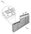
- FIG. 1depicts one embodiment of a solar-powered window covering
- FIG. 2depicts a partial embodiment of a window covering with PV cells mounted to a window blind slat having an inclinometer
- FIG. 3depicts an embodiment of a solar-powered window covering system using a potentiometer that detects a tilt of window covering slats;
- FIG. 4depicts one embodiment of a suitable motor and gearbox for use in a solar-powered window covering
- FIGS. 5A-Bdepict an embodiment of a mechanically adjustable PV cell for use with a solar-powered window covering system
- FIGS. 6A-Cdepict an embodiment of a slat having an internal motor and gear that slides PV cells in tracks on the slat;
- FIG. 7depicts one embodiment of sliding tracks in a slat for a solar-powered window covering system
- FIG. 8depicts an embodiment of sliding tracks around a slat for a solar-powered window covering system
- FIG. 9depicts an example embodiment of a structure in which a solar-powered window covering according to the claimed invention is beneficial
- FIG. 10depicts a digital display and user interface used with some embodiments of the claimed invention.
- FIGS. 11A-Cdepict an alternative embodiment of a mechanism that slides PV cells in tracks along a window blind slat, according to the claimed invention
- FIG. 12depicts one alternative embodiment of tracks in a window covering slat
- FIG. 13depicts an example embodiment of a method for operating a solar powered window covering according to the claimed invention
- FIG. 14depicts another example method for operating a solar powered window covering according to the claimed invention.
- FIG. 15depicts yet another example method for operating a solar powered window covering according to the claimed invention.
- FIG. 16depicts another embodiment of a method for operating a solar powered window covering according to the claimed invention.
- FIG. 17depicts one more embodiment of a method for operating a solar powered window covering according to the claimed invention.
- off-the-shelfmeans “pre-manufactured” and/or “pre-assembled.”
- FIG. 1depicts one embodiment of a solar-powered window covering.
- Window covering system 100includes window covering 101 , headrail 102 , motor and gearbox 103 , one or more tiltable slats 104 , sliding tracks 105 , and photovoltaic (PV) cells 106 .
- at least one slat 104includes sliding track 104 .
- PV cells 106are movably disposed within sliding tracks 105 , and PV cells 106 slide in tracks 105 with regard to an amount of sunlight incident on PV cells 106 .
- window covering 101includes a set of horizontal slats. However, in some embodiments, window covering 101 includes a set of vertical slats.
- Headrail 102is similar to typical headrails used in known window covering systems. Headrail 102 includes a tilt assembly, including a tilt rod and motor and gearbox 103 , and a housing. Headrail 102 mounts window covering 101 over a window associated with system 100 . In some embodiments, headrail 102 also houses a battery for powering motor and gearbox 103 .
- Motor and gearbox 103are, in some embodiments, any of a variety of off-the-shelf motor-and-gearbox assemblies for motorized adjustment of a window covering.
- motor and gearbox 103are automated and remotely controlled, such as the motor and gearbox provided in the Automation Kit sold by MySmartBlinds, a window blind automation retailer.
- Motor and gearbox 103are powered in a variety of ways.
- motor and gearbox 103are battery-powered.
- motor and gearbox 103are powered directly by solar power, with a battery as backup power.
- motor and gearbox 103are powered by mains power and supplemented by battery and/or solar power.
- Slats 104are, in some embodiments, any of a variety of off-the-shelf window blind slats, such as wood slats, aluminum slats, plastic slats, and/or slats made of composite materials.
- slats 104are hollow, and house components for sliding PV cells 106 in tracks 105 (described below in more detail with regard to FIGS. 6A-C ).
- Tracks 105are incorporated with slats 104 to guide PV cells 106 along slats 104 and, in some embodiments, to hold PV cells 106 to slats 104 .
- tracks 105are cut into slats 104 .
- tracks 105include endcaps on slats 104 . Embodiments of tracks 105 are described in more detail with regard to FIGS. 7 and 8 .
- PV cells 106are any of a variety of off-the-shelf flexible PV cells. PV cells 106 are flexible enough to curve around an edge of slats 104 . In some embodiments, PV cells 106 are flexible enough to curve 180° with diameter ranging from 1/16-inch to 1 ⁇ 4-inch. In one such embodiment, PV cells 106 are thin-film solar cells mounted to a flexible plastic substrate.
- PV cells 106slide in tracks 105 across and around slats 104 to maximize an amount of sunlight absorbed by PV cells 106 while still allowing for window covering 101 to be tilted in any desired way.
- window covering 101is tilted so that slats 104 are perpendicular to a window associated with system 100 .
- PV cells 106are positioned on a top side of slats 104 .
- a useradjusts slats 104 to reduce light let into a room associated with system 100 by tilting slats 104 so that slats 104 are nearly parallel to the window, and the top side of slats 104 faces into the room.
- PV cells 106detect the changed tilt and slide in tracks 105 to a bottom side of slats 104 facing the window.
- PV cells 105are positioned on several slats 104 .
- PV cells 105are positioned on all slats 104 .
- PV cells 105are positioned on only a few slats 104 of window covering 101 .
- PV cells 105are positioned on one slat 104 .
- PV cells 104are positioned on a slat 104 with maximum exposure to sunlight (as is described in more detail with regard to FIG. 9 ).
- PV cells 105are controlled in any of a variety of ways. In some embodiments, a position of PV cells 105 on slats 104 is controlled electromechanically via microcontroller and motor. In other embodiments, the position of PV cells 105 on slats 104 is controlled mechanically. Some such electromechanical and mechanical means are described in further detail below with regard to FIGS. 4-6C .
- PV cells 106provide power for operating system 100 . In some embodiments, PV cells 106 directly power motor and gearbox 103 . In the same or other embodiments, PV cells 106 charge a battery that powers motor and gearbox 103 . Additionally, in the same or other embodiments, PV cells 106 power a motor that slides PV cells 106 along slats 104 .
- the batteryis fully charged and the motor and/or motor and gearbox 103 are unused, but PV cells 106 are converting sunlight into power.
- Some embodimentsaddress such cases by including wiring connecting PV cells 106 to a common electricity circuit for a structure associated with system 100 .
- PV cells 106are used to power other electrical devices around the structure, and/or are send power back to a power grid associated with the structure.
- PV cells 106are networked to additional backup batteries.
- system 100includes a light-impermeable covering positioned over PV cells 106 .
- a userdoes not intend to use or adjust a window covering for an extended period of time, such as when the user goes on vacation. In such cases, it is useful to cover PV cells 106 to prevent cells 106 from generating power.
- the coveringis incorporated into each corresponding slat 104 , and slides in tracks 105 to cover PV cells 106 . In another embodiment, the covering is detachable from slats 104 .
- FIG. 2depicts a partial embodiment of a window covering with PV cells mounted to a window blind slat having an inclinometer.
- Window covering 200includes slats 201 , sliding tracks 202 in one slat 201 , PV cells 203 , and inclinometer 204 coupled to at least on slat 201 .
- Inclinometer 204indicated an amount of sunlight incident on PV cells 203 by detecting a tilt of slats 201 .
- Inclinometer 204is any of a variety of off-the-shelf MEMS inclinometers.
- inclinometer 204is hardwired to a microcontroller associated with window covering 200 (not shown, but similar to that described below with regard to FIG. 4 ), and communicates an angle of tilt of slats 201 with the microcontroller.
- the microcontrollerprocesses the tilt information and instructs PV cells 203 to slide in tracks 202 based on the tilt information.
- the microcontrollerstores information about a location on the earth relative to the sun of window covering 200 .
- the microcontrollerstores date and time information, and associates the date and time information with a position of the sun in the sky relative to window covering 200 . Based on tilt information sent to the microcontroller from inclinometer 204 , and based on the position of the sun in the sky, the microcontroller sends instructions to adjust PV cells 203 to maximize power generated by PV cells 203 .
- the sunis at its apex in the sky
- inclinometer 204indicates a top side 201 a of slats 201 is perpendicular to light emanating from the sun. Based on that indication, PV cells 203 are slid in tracks 202 to the top side 201 a .
- inclinometer 204indicates a bottom side of slats 201 is perpendicular to light emanating from the sun. Based on that indication, PV cells 203 are slid in tracks 202 to the bottom side of slats 201 .
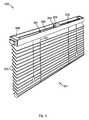
- FIG. 3depicts an embodiment of a solar-powered window covering system using a potentiometer that detects a tilt of window covering slats.
- System 300includes window covering 301 , headrail 302 , motor and gearbox 303 , potentiometer 304 , slats 305 , tilt rod 306 , strings 307 , and battery 308 .
- Potentiometer 304is coupled to strings 307 (as depicted, via tilt rod 306 ), and strings 307 tilt slats 305 .
- Potentiometer 304indicates an amount of sunlight incident on PV cells associated with system 300 (not shown, but similar to that described above with regard to FIGS. 1-2 ) by detecting a tilt of slats 305 .
- Potentiometer 304is any of a variety of off-the-shelf potentiometers.
- Tilt rod 306extends through motor and gearbox 303 and across headrail 302 .
- Tilt rod 306is made of any of a variety of materials suitable for sustaining rotational strain.
- String 307is coupled to tilt rod 306 and provides support for slats 305 .
- String 307is made of any of a variety of materials, such as nylon, polyester, cotton, or other polymers commonly used for string.
- Battery 308is any of a variety of off-the-shelf rechargeable batteries.
- Battery 308stores at least enough energy to power motor and gearbox 303 for 6-12 months of regular use. For example, in one embodiment, battery 308 stores enough power for 10 adjustments per day for 12 months before needing a recharge (without solar charging). As depicted, battery 308 is positioned in headrail 302 . However, in other embodiments, battery 308 is positioned outside headrail 302 . In yet other embodiments, battery 308 is housed inside motor and gearbox 303 .
- potentiometer 304is indirectly coupled to string 307 via tilt rod 306 .
- potentiometer 304is directly coupled to tilt rod 306 .
- potentiometer 304is directly coupled to string 307 .
- Potentiometer 304indicates a tilt of slats 305 by conveying a voltage to a microcontroller (not shown, but similar to the microcontroller described below with regard to FIG. 4 ).
- the microcontrollerstores an algorithm that associates a voltage indicated by potentiometer 304 with a tilt of slats 305 .
- the microcontrollercalculates the tilt of slats 305 and slides the PV cells in tracks in slats 305 (not depicted but similar to that described above with regard to FIGS. 1-2 ), maximizing an amount of sunlight incident on the PV cells.
- the microcontrollerstores a table that associates the voltage indicated by potentiometer 304 with the tilt of the slats.
- FIG. 4depicts one embodiment of a suitable motor and gearbox for use in a solar-powered window covering.
- Motor and gearbox 400includes motor 401 , gears 402 , printed circuit board (PCB) 403 , microcontroller 404 , transceiver 405 , antenna 406 , output shaft 407 , and tilt rod coupler 408 .
- microcontroller 404is programmed with instructs to instruct motor 401 to tilt slats (not shown, but similar to those depicted in FIGS. 1-3 ) to maximize a current generated by one or more PV cells on the slats (not depicted, but similar to those depicted in FIGS. 1-3 ).
- Motor 401is any of a variety of off-the-shelf and/or custom manufactured DC motors capable of handling loads up to the combined weight of the slats. However, depending on the gear ratio of gears 402 relative to output shaft 407 (described in more detail below), motor 401 can have a maximum load capacity of much less than the combined weight of the slats. Motor 401 is powered in a variety of ways. In some embodiments, motor 401 is directly powered by the PV cells. In the same or other embodiments, motor 401 is indirectly powered by the PV cells via a battery charged by the PV cells. Similarly, some embodiments include powering motor 401 via mains power.
- Gears 402have one or more stages of gears to reduce the gear ratio of motor 401 .
- the gear ratiomay be between 100:1 and 1000:1.
- the gear ratiois 720:1 (i.e., seven hundred and twenty turns of the motor 401 produces a single turn of tilt rod coupler 408 ).
- PCB 403is any of a variety of off-the-shelf and/or custom manufactured PCBs. As depicted, PCB 403 is oriented vertically in motor and gearbox 400 . However, PCB 403 is oriented in a variety of other ways in other embodiments. For example, in one embodiment, PCB 403 is mounted above motor 401 and gears 402 . In another embodiment, PCB 403 is mounted below motor 401 and gears 402 . In yet another embodiment, PCB 403 is housed and mounted separately from motor and gearbox 400 in a headrail of the solar-powered window covering. PCB 403 networks microcontroller 404 with transceiver 405 and motor 401 .
- Components networked to PCB 403are powered in a variety of ways, such as directly by the PV cells, indirectly by the PV cells via a battery, or at least in part by mains power.
- Microcontroller 404 and transceiver 405are any of a variety of off-the-shelf and/or custom manufactured devices.
- transceiver 405is one or more of a WiFi transceiver, Bluetooth transceiver, Zigbee transceiver, or Z-wave transceiver.
- transceiver 405is a SureFi transceiver (SureFi is a long-range, low data wireless spread spectrum frequency hopping protocol on the 902-928 MHz ISM band).
- Antenna 406is an antenna suitable for use with transceiver 405 .
- output shaft 407drives gears 402 coupled to output shaft 407 .
- Output shaft 407drives a tilt rod (not shown, but similar to that depicted above with regard to FIGS. 1 and 3 ).
- output shaft 407extends the length of motor and gearbox 400 .
- Output shaft 407includes a through-channel, extending the length of the output shaft 407 , to enable the tilt rod to pass therethrough.
- the through-channel(along with any required adapter inserts) includes tilt rod coupler 408 that interlocks with, and applies torque to, the tilt rod.
- output shaft 407rides on bearing surfaces at each end of motor and gearbox 400 .
- Microcontroller 404stores instructions for operating motor 401 and, in some embodiments, for sliding the PV cells in tracks along the slats.
- microcontroller 404receives tilt information about the slats, such as from an inclinometer or potentiometer (similar to those described above with regard to FIGS. 2-3 , respectively). Based on the tilt information, microcontroller 404 instructs the PV cells to adjust position by sliding in the tracks.
- microcontroller 404also controls power allocation of power generated by the PV cells. For example, in some embodiments, microcontroller 404 directs power from the PV cells to charge a battery.
- microcontroller 404diverts power from charging the PV cells to power motor 401 . In embodiments where the PV cells do not generate enough power to fully power motor 401 , microcontroller 404 additionally draws power from the battery to power motor 401 .
- FIGS. 5A-Bdepict an embodiment of a mechanically adjustable PV cell for use with a solar-powered window covering system.
- PV cells 501are positioned on window covering slat 502 .
- Rigid coupling member 503couples PV cells 501 to outside edge 504 b of slat 504 above PV cells 501 and slat 502 .
- Coupling member 503forces PV cells 501 to slide in tracks (not shown, but similar to the tracks described above with regard to FIGS. 1-2 ) when a tilt of the window covering is adjusted.
- Slats 502 and 504are hung from a headrail by string 506 , and PV cells 501 transmit.
- FIG. 5Bdepicts slats 502 , 504 tilted such that top sides 502 a , 504 a of each slat faces window side 507 of the window covering system.
- slats 502 , 504are tilted as such, a distance between center point 502 b and outside edge 504 b increases, whereas a length of rigid coupler 503 remains fixed.
- PV cells 501are pulled by rigid coupler 503 over a larger section of top side 502 a .
- This embodimentis particularly beneficial where PV cells 501 cover a portion of width 502 c when slat 502 is horizontally tilted that is less in length than inter-slat spacing 508 .
- FIGS. 6A-Cdepict an embodiment of a slat having an internal motor and gear that slides PV cells in tracks on the slat.
- slat 601includes PV cells 602 , motor 603 , gear 604 , and power transfer rod 605 .
- Motor 603 , gear 604 and power transfer rod 605are embedded in slat 601 .
- Motor 603 and gear 604force PV cells 602 to slide in tracks (depicted in FIG. 6B , and similar to those depicted in FIGS. 1-2 above) when a tilt of a window covering associated with slat 601 is adjusted.
- Motor 603is a DC micro-motor having a thickness ranging from 1-6 mm. In some embodiments, several motors 603 are necessary to slide PV cells 602 in the tracks. PV cells 602 are mounted to flexible material 602 a . In some embodiments, motor 603 is coupled to several gears 604 disposed along power transfer rod 605 . Additionally, in some alternative embodiments, motor 603 transfers power to gear 604 via a horizontal gear. In some embodiments, a gear ratio between motor 603 and gear 604 ranges from 1:1 to 1000:1 (motor rotations:gear rotations). Gear 604 is positioned in the sliding track.
- flexible material 602 aincludes perforations 602 b to fit over teeth of gear 604 . As gear 604 rotates, gear 604 engages flexible material 602 a and slides PV cells 602 in sliding track 606 . As depicted in FIG. 6C , in some embodiments, flexible material 602 a includes teeth 607 protruding into track 606 that engage teeth of gear 604 .
- FIG. 7depicts one embodiment of sliding tracks in a slat for a solar-powered window covering system.
- Slat 701includes track 702 .
- Flexible material 703includes flanged track guide 704 and PV cells 705 .
- Flanged track guide 704fits into track 702 and prevents flexible material 703 from disengaging with, and falling off of, slat 701 .
- FIG. 8depicts another embodiment of sliding tracks in a slat for a solar-powered window covering system.
- Slat 801includes track 802 positioned at outside edge 801 a , around slat 801 .
- Flexible material 803fits into track 802 between slat 801 and track 802 .
- FIG. 9depicts an example embodiment of a structure where a solar-powered window covering according to the claimed invention is beneficial.
- Structure 901includes window 902 .
- Sunlight 903is partially obstructed by awning 904 if structure 901 .
- portion 902 a of window 902does not receive sunlight for some of the day, whereas portion 902 b receives sunlight throughout the entire day.
- FIG. 10depicts a digital display and user interface used with some embodiments of the claimed invention.
- Control unit 1000includes case 1001 and user interface 1002 .
- User interface 1002indicates, tilt 1004 of an associated window covering, and position 1003 of the sun in the sky.
- user interface 1002receives inputs from a user.
- Control unit 1000is, in some embodiments, programmed with position 1003 of the sun in the sky based on a date and time, and is further programmed with corresponding ideal tilts 1004 for respective positions 1003 of the sun in the sky.
- tilt 1004is related to position 1003 by an algorithm including an angle of the sun above the horizon and an orientation of a window covering with respect to the sun.
- FIGS. 11A-Cdepict an alternative embodiment of a mechanism that slides PV cells in tracks along a window blind slat, according to the claimed invention.
- slat 1101includes gears 1102 , 1103 embedded in slat 1101 .
- Gear 1102engages PV cells 1104
- gear 1103engages gear 1102 and string 1105 .
- String 1105passes through slat 1101 and engages gear 1103 .
- Motion of gear 1103 across string 1105 as slat 1101 is tiltedrotates gear 1103 , in turn rotating gear 1105 and sliding PV cells 1102 in tracks on slat 1101 across slat 1101 .
- string 1105engages gear 1103 by friction rollers 1106 , 1107 .
- String 1105passes between rollers 1106 , 1107 , in contact with each, such that motion of rollers 1106 , 1107 across string 1105 causes rollers 1106 , 1107 to rotate.
- Roller 1106is coupled to gear 1103 , either directly or indirectly through a gear ratio reducer, which reduces the number of rotations of roller 1106 per rotation of gear 1103 .
- FIG. 12depicts one alternative embodiment of tracks in a window covering slat.
- tracks 1201run along both a length and width of slat 1202 .
- PV cells 1203slide in tracks 1202 along two dimensions of slat 1202 .
- FIG. 13depicts an example embodiment of a method for operating a solar powered window covering according to the claimed invention.
- Method 1300includes, at 1301 , detecting a tilt of at least one window covering slate.
- the slatincludes one or more PV cells disposed in sliding tracks in the slate, the and tilt indicates an amount of sunlight incident on the PV cells.
- the PV cellsare slid in the tracks with regard to the amount of sunlight incident on the cells, maximizing the amount of incident sunlight.
- Method 1300also includes adjusting the tilt of the slats to maximize the amount of incident sunlight.
- detecting the tiltincludes detecting a position of one or more strings that tilt the slat, such as using a potentiometer (similar to that described with regard to FIG. 3 ).
- Method 1300is accomplished in any of a variety of ways using any of a variety of components. For example, in some embodiments, Method 1300 is accomplished using the components described above with regard to FIGS. 1-8 and 11A -D.
- FIG. 14depicts another example method for operating a solar powered window covering according to the claimed invention.
- Method 1400includes, at block 1401 , obtaining a position of the sun in the sky.
- a slatis positioned in the window covering to maximize an amount of time the slat is exposed to sunlight relative to the entire window covering.
- a tilt of the slatis detected.
- the slatincludes one or more PV cells.
- the PV cellsare slid in the tracks with regard to the amount of sunlight incident on the cells, maximizing the amount of incident sunlight. Sliding the PV cells is also based on the position of the sun in the sky. Similar to method 1300 , method 1400 is accomplished in any of a variety of ways using any of a variety of components, such as those described with regard to FIGS. 1-8 and 10-11D .
- FIG. 15depicts yet another example method for operating a solar powered window covering according to the claimed invention.
- Method 1500includes, at block 1501 , detecting an amount of electrical current generated by a first PV cell disposed in sliding tracks in a window covering slat.
- an amount of electrical current generated by a second PV cell disposed in the sliding tracksis detected.
- the amounts of currentare compared.
- the PV cellsare slid in the tracks in a direction associated with the cell with the largest current.
- Method 1500is accomplished, for example, by calculations performed by a processor.
- the processorassociates the PV cells with an orientation relative to each other cell and relative to the slat.
- the processorcalculates which PV cells are generating the most current, and slide the entire set of PV cells along the current gradient in the direction of increasing current.
- a previously measured current for all the PV cellsis compared to a new current for the new position of the PV cells.
- the PV cellsare continuously slid in the same direction until the new current is less than the previous current.
- comparing the amounts of currentcomparing the amounts of current to a minimum threshold.
- the PV cellsare slid in the direction when at least one of the currents is above the minimum threshold. In other embodiments, a minimum current difference must be met before the PV cells are repositioned.
- FIG. 16depicts another embodiment of a method for operating a solar powered window covering according to the claimed invention.
- Method 1600includes, at block 1601 , detecting an amount of electrical current generated by a first PV cell disposed in sliding tracks in a window covering slat.
- an amount of electrical current generated by a second PV cell disposed in the sliding tracksis detected.
- the amounts of currentare compared.
- a position of the sin in the skyis obtained.
- the PV cellsare slid in the tracks in a direction associated with the cell with the largest current. The sliding is additionally based on the position of the sin in the sky.
- FIG. 17depicts one more embodiment of a method for operating a solar powered window covering according to the claimed invention.
- a slatis positioned in a window covering to maximize an amount tome the slat is exposed to sunlight relative to the entire window covering.
- an amount of electrical current generated by a first PV cell disposed in sliding tracks in the window covering slatis detected.
- an amount of electrical current generated by a second PV cell disposed in the sliding tracksis detected.
- the amounts of currentare compared.
- the PV cellsare slid in the tracks in a direction associated with the cell with the largest current.
Landscapes
- Engineering & Computer Science (AREA)
- Structural Engineering (AREA)
- Architecture (AREA)
- Civil Engineering (AREA)
- Life Sciences & Earth Sciences (AREA)
- Sustainable Development (AREA)
- Blinds (AREA)
Abstract
Description
Claims (20)
Priority Applications (2)
| Application Number | Priority Date | Filing Date | Title |
|---|---|---|---|
| US15/220,969US10458179B2 (en) | 2016-07-27 | 2016-07-27 | Solar-powered window covering |
| PCT/US2017/043917WO2018022737A2 (en) | 2016-07-27 | 2017-07-26 | Solar-powered window covering |
Applications Claiming Priority (1)
| Application Number | Priority Date | Filing Date | Title |
|---|---|---|---|
| US15/220,969US10458179B2 (en) | 2016-07-27 | 2016-07-27 | Solar-powered window covering |
Publications (2)
| Publication Number | Publication Date |
|---|---|
| US20180030781A1 US20180030781A1 (en) | 2018-02-01 |
| US10458179B2true US10458179B2 (en) | 2019-10-29 |
Family
ID=61009318
Family Applications (1)
| Application Number | Title | Priority Date | Filing Date |
|---|---|---|---|
| US15/220,969Expired - Fee RelatedUS10458179B2 (en) | 2016-07-27 | 2016-07-27 | Solar-powered window covering |
Country Status (2)
| Country | Link |
|---|---|
| US (1) | US10458179B2 (en) |
| WO (1) | WO2018022737A2 (en) |
Cited By (6)
| Publication number | Priority date | Publication date | Assignee | Title |
|---|---|---|---|---|
| US10934770B2 (en)* | 2016-07-20 | 2021-03-02 | Navus Consulting Cc | Slat for a blind and blind formed therefrom |
| US20220049545A1 (en)* | 2020-08-12 | 2022-02-17 | Thuytrinh Pham | Power Generating Blind Assembly |
| US20220205315A1 (en)* | 2020-12-30 | 2022-06-30 | Hall Labs Llc | Multiple independent shade array |
| US20240191909A1 (en)* | 2013-05-12 | 2024-06-13 | Sigmagen, Inc. | Solar photovoltaic blinds and curtains for residential and commercial buildings |
| US20240418035A1 (en)* | 2022-12-19 | 2024-12-19 | Morgan Solar Inc. | Solar window blind systems |
| US20250075557A1 (en)* | 2020-12-24 | 2025-03-06 | Kyocera Corporation | Blind apparatus |
Families Citing this family (12)
| Publication number | Priority date | Publication date | Assignee | Title |
|---|---|---|---|---|
| US10458179B2 (en)* | 2016-07-27 | 2019-10-29 | Hall Labs Llc | Solar-powered window covering |
| US10113360B2 (en)* | 2016-12-09 | 2018-10-30 | Hall Labs Llc | Roll-up wall tensioning |
| KR101935802B1 (en)* | 2017-01-11 | 2019-01-07 | 엘지전자 주식회사 | Window blind |
| KR102206065B1 (en)* | 2017-06-01 | 2021-01-21 | (주)엘지하우시스 | Blind slat assembly having ability of solar generation |
| US20190162014A1 (en)* | 2017-09-29 | 2019-05-30 | Gleason Partners Llc | Solar transparent pv window awning power actuated to adjust to sun position making existing windows more efficient produce electricity and reduce building air conditioning usage |
| US10892703B2 (en) | 2018-05-18 | 2021-01-12 | Nextracker Inc. | Methods and systems for detecting shading for solar trackers |
| US10560050B2 (en)* | 2018-06-15 | 2020-02-11 | Evolusun, Inc. | Innovative energy generating photovoltaic awning |
| US11658607B2 (en)* | 2018-10-17 | 2023-05-23 | Scuola universitaria professionale della Svizzera italiana (SUPSI) | Building-integrated photovoltaic apparatus, in particular for windows and the like, a method and a slat for said apparatus |
| AT523955A3 (en)* | 2020-06-15 | 2022-01-15 | Noah Roshdy | External sun protection for windows (venetian blind) with solar slats to generate electricity |
| WO2022117669A1 (en)* | 2020-12-02 | 2022-06-09 | Dalton Wilson Michael | Smart remote system |
| JP2025014095A (en)* | 2021-12-24 | 2025-01-29 | 京セラ株式会社 | Blind device and control method |
| US20230208344A1 (en)* | 2021-12-24 | 2023-06-29 | Josefina Cruz | Optimally-placed, wall-mounted solar device |
Citations (86)
| Publication number | Priority date | Publication date | Assignee | Title |
|---|---|---|---|---|
| US3039155A (en)* | 1959-10-07 | 1962-06-19 | Victor S Iacovoni | Awning window |
| US4091592A (en)* | 1977-04-29 | 1978-05-30 | The United States Of America As Represented By The United States Department Of Energy | Low heat transfer, high strength window materials |
| US4159710A (en)* | 1976-09-20 | 1979-07-03 | U.S. Philips Corporation | Solar collector comprising solar tracking means |
| US4304218A (en)* | 1979-08-24 | 1981-12-08 | Jon Karlsson | Solar energy collector |
| US5221363A (en)* | 1991-02-28 | 1993-06-22 | Lockheed Missiles & Space Company, Inc. | Solar cell window fitting |
| US5413161A (en)* | 1993-09-09 | 1995-05-09 | Corazzini; Warren | Solar powered window shade |
| US5517094A (en)* | 1993-07-20 | 1996-05-14 | Harmonic Design, Inc. | Head rail-mounted mini-blind actuator |
| US5532560A (en)* | 1994-11-08 | 1996-07-02 | Sun Dial Industries, Inc. | Photosensitive automatic blind controller |
| US5698958A (en)* | 1993-06-11 | 1997-12-16 | Harmonic Design, Inc. | Head rail-mounted actuator for window coverings |
| US5760558A (en)* | 1995-07-24 | 1998-06-02 | Popat; Pradeep P. | Solar-powered, wireless, retrofittable, automatic controller for venetian blinds and similar window converings |
| US5793174A (en)* | 1996-09-06 | 1998-08-11 | Hunter Douglas Inc. | Electrically powered window covering assembly |
| US5818183A (en)* | 1994-12-06 | 1998-10-06 | Auto-Tilt Enterprises, Ltd. | Blind tilt controller |
| US6060852A (en)* | 1993-06-11 | 2000-05-09 | Harmonic Design, Inc. | Head rail-mounted actuator for window covering |
| US6239910B1 (en)* | 1999-02-12 | 2001-05-29 | Architectural Energy Corporation | Mini-optical light shelf daylighting system |
| US6378248B1 (en)* | 2000-09-25 | 2002-04-30 | Robert L. Jordal | Dual panel jalousie assembly with independent panel movement |
| US20030168056A1 (en)* | 2002-03-08 | 2003-09-11 | Fidler John Frederick | Venetian blind type solar heater |
| US6789597B2 (en)* | 2002-03-07 | 2004-09-14 | Industrial Technology Research Institute | Electromagnetic clutch-controlled electric blind |
| US6812662B1 (en)* | 2002-04-01 | 2004-11-02 | Harmonic Design, Inc. | Photoelectric power supply system for motorized window coverings |
| US20050022946A1 (en)* | 2003-07-31 | 2005-02-03 | Douglas Domel | Drive mechanism for motorized window coverings |
| US20050102934A1 (en)* | 2003-11-13 | 2005-05-19 | Winarski Tyson Y. | Window that generates solar-power electricity |
| US7077123B2 (en)* | 2001-02-20 | 2006-07-18 | Jaervinen Simo | Isolation shield system, insolation shield and method |
| US20070056579A1 (en)* | 2005-09-09 | 2007-03-15 | Straka Christopher W | Energy Channeling Sun Shade System and Apparatus |
| US20070163732A1 (en)* | 2006-01-13 | 2007-07-19 | Konvin Associates Ltd. | Method and device for controlling the passage of radiant energy into architectural structures |
| US20070251569A1 (en)* | 2006-01-25 | 2007-11-01 | Intematix Corporation | Solar modules with tracking and concentrating features |
| US20090114264A1 (en)* | 2007-10-25 | 2009-05-07 | Gianrocco Giampietro | Fixed-geometry and/or variable-geometry surfaces for capturing solar energy by means of photovoltaic cells, films, and panels, in particular for watercraft |
| GB2455753A (en)* | 2007-12-20 | 2009-06-24 | Enecsys Ltd | Blind with photovoltaic panels |
| US7617857B2 (en)* | 2006-02-02 | 2009-11-17 | Brad Froese | Illuminated window blind assembly |
| US20100243025A1 (en)* | 2009-03-27 | 2010-09-30 | Bhatia Sneha P | Window[s] Treatment |
| US20100275534A1 (en)* | 2009-05-04 | 2010-11-04 | Raymond Henry Ruskin | Continuous circuit overlay solar shingles |
| US20110007498A1 (en)* | 2009-07-10 | 2011-01-13 | Osram Gesellschaft Mit Beschraenkter Haftung | Illumination device with a solar cell |
| US20110030761A1 (en)* | 2009-08-10 | 2011-02-10 | Kalkanoglu Husnu M | Roofing products, photovoltaic roofing elements and systems using them |
| US20110048656A1 (en)* | 2009-08-28 | 2011-03-03 | Electronics And Telecommunications Research Institute | Blind device using solar cells |
| US20110126992A1 (en)* | 2008-06-04 | 2011-06-02 | Mariana Yordanova | Blind device for light protection and displaying of information |
| US20110214712A1 (en)* | 2008-08-06 | 2011-09-08 | Scott Frazier | Solar energy conversion |
| US20110251720A1 (en)* | 2007-11-16 | 2011-10-13 | Somfy Sas | Method for the automated control of a sun-shading device |
| US20110253319A1 (en)* | 2010-04-16 | 2011-10-20 | Schaupp John F | Blind or shade |
| US20120011782A1 (en)* | 2009-01-27 | 2012-01-19 | Kolaas Tore | Fenestration system with solar cells |
| US20120073765A1 (en)* | 2010-09-17 | 2012-03-29 | Lutron Electronics Co., Inc. | Motorized Venetian Blind System |
| US20120152469A1 (en)* | 2010-01-14 | 2012-06-21 | Lg Hausys, Ltd. | Photovoltaic blind window |
| WO2012087019A2 (en)* | 2010-12-23 | 2012-06-28 | (주)테라솔라 | 2-axis tracking apparatus and sunshade apparatus comprising same |
| US20120167872A1 (en)* | 2010-12-29 | 2012-07-05 | Chia-Yen Lin | Solar Energy Collecting Device |
| US20120173143A1 (en)* | 2008-09-15 | 2012-07-05 | Trex Enterprises Corp. | Celestial compass kit |
| US20120216964A1 (en)* | 2011-02-27 | 2012-08-30 | Peng Xu | Shading devices |
| US20120273023A1 (en)* | 2011-04-28 | 2012-11-01 | Ely Jonathan | Collapsible reflector for solar panel |
| US20120299470A1 (en)* | 2010-01-07 | 2012-11-29 | Sharp Kabushiki Kaisha | Illumination device having multiple light emitting panels |
| US8338694B2 (en)* | 2008-06-07 | 2012-12-25 | Sun Synchrony | Solar energy collection system |
| US8365800B2 (en)* | 2008-12-22 | 2013-02-05 | Samsung Electronics Co., Ltd. | Blind with solar batteries and control method thereof |
| US8365468B2 (en)* | 2008-02-11 | 2013-02-05 | Eastern Metal Supply, Inc. | Metal bahama style storm shutter |
| US8413705B2 (en)* | 2008-09-09 | 2013-04-09 | Jean-Louis Castel | Orientable panel of a roofing device |
| US20130146123A1 (en)* | 2009-06-03 | 2013-06-13 | Ken Hyun Park | Solar Panel Tracking and Mounting System |
| US8471464B2 (en)* | 2010-02-17 | 2013-06-25 | Sharp Kabushiki Kaisha | Integrated illumination apparatus and method of manufacturing same |
| US8477081B2 (en)* | 2009-01-21 | 2013-07-02 | Palo Alto Research Center Incorporated | Louver device |
| US20130199515A1 (en)* | 2012-01-24 | 2013-08-08 | Mbc Ventures, Inc. | Skylight energy management system |
| US20130206213A1 (en)* | 2012-02-15 | 2013-08-15 | Alta Devices, Inc. | Photovoltaic module containing shingled photovoltaic tiles and fabrication processes thereof |
| US8525462B2 (en)* | 2005-03-08 | 2013-09-03 | Mechoshade Systems, Inc. | Automated shade control method and system |
| US8528621B2 (en)* | 2012-02-01 | 2013-09-10 | Murphy-Farrell Development L.L.L.P. | Solar window shade |
| US20130247954A1 (en)* | 2010-10-29 | 2013-09-26 | Sma Solar Technology Ag | Window or Door Having a Photovoltaic Module |
| US20130278989A1 (en)* | 2010-12-15 | 2013-10-24 | Switch Materials, Inc. | Variable transmittance optical devices |
| US20140020852A1 (en)* | 2011-03-10 | 2014-01-23 | Venetian Solar Aps | Window shutter unit for external mounting on a building |
| US8678067B2 (en)* | 2008-12-30 | 2014-03-25 | Koninklijke Philips N.V. | Posture-adjustable solar-collecting window blind |
| US20140102510A1 (en)* | 2012-10-12 | 2014-04-17 | Cogenra Solar, Inc. | Concentrating solar energy collector |
| US20140111007A1 (en)* | 2012-10-19 | 2014-04-24 | Institute Of Nuclear Energy Research Atomic Energy Council, Executive Yuan | Flexible thin film solar shutter |
| US20140116497A1 (en)* | 2012-10-31 | 2014-05-01 | Wyatt Sanders | Building Integrated Solar Aperture Fixtures |
| US8723466B2 (en)* | 2010-09-17 | 2014-05-13 | Lutron Electronics Co., Inc. | Motorized venetian blind system |
| US8820388B2 (en)* | 2010-10-18 | 2014-09-02 | Qmotion Incorporated | Motorizable shade system and method |
| US8837049B2 (en)* | 2012-03-26 | 2014-09-16 | Mbc Ventures, Inc. | Window blind solar energy management system |
| US8939190B2 (en)* | 2010-10-18 | 2015-01-27 | QMotion Limited | Motorizable tilt shade system and method |
| US20150096607A1 (en)* | 2012-05-09 | 2015-04-09 | iTouch Energy Limited | Solar cell module and systems incorporating same |
| US20150101761A1 (en)* | 2013-05-12 | 2015-04-16 | Solexel, Inc. | Solar photovoltaic blinds and curtains for residential and commercial buildings |
| US9057535B2 (en)* | 2006-07-10 | 2015-06-16 | Mbc Ventures, Inc. | Solar energy conversion devices and systems |
| US9091115B2 (en)* | 2010-10-18 | 2015-07-28 | Qmotion Incorporated | Motorizable tilt shade system and method |
| US9163452B2 (en)* | 2010-04-30 | 2015-10-20 | Hangzhou Wokasolar Technology Co., Ltd. | Multi-slat combination blind of rotating type |
| US20150348401A1 (en)* | 2014-04-08 | 2015-12-03 | David R. Hall | Universal Multi-Function Wall Switch |
| US20160064588A1 (en)* | 2014-08-28 | 2016-03-03 | James B. Paull | Concentrator lens for directing light to a photovoltaic target or mirrored surface and a dynamic window apparatus utilizing the same |
| US20170138124A1 (en)* | 2014-07-02 | 2017-05-18 | Sharp Kabushiki Kaisha | Daylighting slat and daylighting device |
| US20170149375A1 (en)* | 2015-05-18 | 2017-05-25 | Alion Energy, Inc. | Systems and methods for rotating photovoltaic modules |
| WO2017086810A1 (en)* | 2015-11-20 | 2017-05-26 | "Moa" Spółka Cywilna | Photovoltaic louver |
| US9695634B2 (en)* | 2011-12-07 | 2017-07-04 | Philips Lighting Holding B.V. | Auto-calibration of blinds systems in buildings |
| US20170204658A1 (en)* | 2014-02-07 | 2017-07-20 | Solarswing Holding B.V. | Orienting device, solar tracking system and method therefor |
| US20180023338A1 (en)* | 2016-07-22 | 2018-01-25 | Bruce M. Werner | Various Systems of Sculptural Slats and Methods of Manufacture Thereof |
| US20180030781A1 (en)* | 2016-07-27 | 2018-02-01 | David R. Hall | Solar-Powered Window Covering |
| US20180076762A1 (en)* | 2016-09-09 | 2018-03-15 | David R. Hall | Photovoltaic Modular System |
| US20180097471A1 (en)* | 2010-12-31 | 2018-04-05 | Certainteed Corporation | Photovoltaic Roofing Elements And Photovoltaic Roofing Systems |
| US20180195766A1 (en)* | 2017-01-11 | 2018-07-12 | Lg Electronics Inc. | Window blind |
| US20180204967A1 (en)* | 2017-01-18 | 2018-07-19 | David R. Hall | Segmented Solar Module |
| US20180283734A1 (en)* | 2017-03-24 | 2018-10-04 | Elliot Tarabour | Solar collection apparatus with elongated slats, integrated tracking and decoupled axes |
- 2016
- 2016-07-27USUS15/220,969patent/US10458179B2/ennot_activeExpired - Fee Related
- 2017
- 2017-07-26WOPCT/US2017/043917patent/WO2018022737A2/ennot_activeCeased
Patent Citations (95)
| Publication number | Priority date | Publication date | Assignee | Title |
|---|---|---|---|---|
| US3039155A (en)* | 1959-10-07 | 1962-06-19 | Victor S Iacovoni | Awning window |
| US4159710A (en)* | 1976-09-20 | 1979-07-03 | U.S. Philips Corporation | Solar collector comprising solar tracking means |
| US4091592A (en)* | 1977-04-29 | 1978-05-30 | The United States Of America As Represented By The United States Department Of Energy | Low heat transfer, high strength window materials |
| US4304218A (en)* | 1979-08-24 | 1981-12-08 | Jon Karlsson | Solar energy collector |
| US5221363A (en)* | 1991-02-28 | 1993-06-22 | Lockheed Missiles & Space Company, Inc. | Solar cell window fitting |
| US5698958A (en)* | 1993-06-11 | 1997-12-16 | Harmonic Design, Inc. | Head rail-mounted actuator for window coverings |
| US6060852A (en)* | 1993-06-11 | 2000-05-09 | Harmonic Design, Inc. | Head rail-mounted actuator for window covering |
| US5907227A (en)* | 1993-06-11 | 1999-05-25 | Harmonic Design, Inc. | Head rail-mounted actuator for window coverings |
| US5517094A (en)* | 1993-07-20 | 1996-05-14 | Harmonic Design, Inc. | Head rail-mounted mini-blind actuator |
| US5413161A (en)* | 1993-09-09 | 1995-05-09 | Corazzini; Warren | Solar powered window shade |
| US5532560A (en)* | 1994-11-08 | 1996-07-02 | Sun Dial Industries, Inc. | Photosensitive automatic blind controller |
| US5818183A (en)* | 1994-12-06 | 1998-10-06 | Auto-Tilt Enterprises, Ltd. | Blind tilt controller |
| US5760558A (en)* | 1995-07-24 | 1998-06-02 | Popat; Pradeep P. | Solar-powered, wireless, retrofittable, automatic controller for venetian blinds and similar window converings |
| US5793174A (en)* | 1996-09-06 | 1998-08-11 | Hunter Douglas Inc. | Electrically powered window covering assembly |
| US6239910B1 (en)* | 1999-02-12 | 2001-05-29 | Architectural Energy Corporation | Mini-optical light shelf daylighting system |
| US6378248B1 (en)* | 2000-09-25 | 2002-04-30 | Robert L. Jordal | Dual panel jalousie assembly with independent panel movement |
| US7077123B2 (en)* | 2001-02-20 | 2006-07-18 | Jaervinen Simo | Isolation shield system, insolation shield and method |
| US6789597B2 (en)* | 2002-03-07 | 2004-09-14 | Industrial Technology Research Institute | Electromagnetic clutch-controlled electric blind |
| US20030168056A1 (en)* | 2002-03-08 | 2003-09-11 | Fidler John Frederick | Venetian blind type solar heater |
| US6812662B1 (en)* | 2002-04-01 | 2004-11-02 | Harmonic Design, Inc. | Photoelectric power supply system for motorized window coverings |
| US20050022946A1 (en)* | 2003-07-31 | 2005-02-03 | Douglas Domel | Drive mechanism for motorized window coverings |
| US20050102934A1 (en)* | 2003-11-13 | 2005-05-19 | Winarski Tyson Y. | Window that generates solar-power electricity |
| US8525462B2 (en)* | 2005-03-08 | 2013-09-03 | Mechoshade Systems, Inc. | Automated shade control method and system |
| US20070056579A1 (en)* | 2005-09-09 | 2007-03-15 | Straka Christopher W | Energy Channeling Sun Shade System and Apparatus |
| US20070163732A1 (en)* | 2006-01-13 | 2007-07-19 | Konvin Associates Ltd. | Method and device for controlling the passage of radiant energy into architectural structures |
| US20090151878A1 (en)* | 2006-01-13 | 2009-06-18 | Konvin Associates Ltd. | Method and device for controlling the passage of radiant energy into architectural structures |
| US20070251569A1 (en)* | 2006-01-25 | 2007-11-01 | Intematix Corporation | Solar modules with tracking and concentrating features |
| US7617857B2 (en)* | 2006-02-02 | 2009-11-17 | Brad Froese | Illuminated window blind assembly |
| US9057535B2 (en)* | 2006-07-10 | 2015-06-16 | Mbc Ventures, Inc. | Solar energy conversion devices and systems |
| US20090114264A1 (en)* | 2007-10-25 | 2009-05-07 | Gianrocco Giampietro | Fixed-geometry and/or variable-geometry surfaces for capturing solar energy by means of photovoltaic cells, films, and panels, in particular for watercraft |
| US8624529B2 (en)* | 2007-11-16 | 2014-01-07 | Somfy Sas | Method for the automated control of a solar protection installation |
| US20110251720A1 (en)* | 2007-11-16 | 2011-10-13 | Somfy Sas | Method for the automated control of a sun-shading device |
| GB2455753A (en)* | 2007-12-20 | 2009-06-24 | Enecsys Ltd | Blind with photovoltaic panels |
| US8365468B2 (en)* | 2008-02-11 | 2013-02-05 | Eastern Metal Supply, Inc. | Metal bahama style storm shutter |
| US20110126992A1 (en)* | 2008-06-04 | 2011-06-02 | Mariana Yordanova | Blind device for light protection and displaying of information |
| US9261630B2 (en)* | 2008-06-07 | 2016-02-16 | Sun Synchrony, Inc. | Solar energy collection system |
| US8338694B2 (en)* | 2008-06-07 | 2012-12-25 | Sun Synchrony | Solar energy collection system |
| US20160258654A1 (en)* | 2008-06-07 | 2016-09-08 | Sun Synchrony, Inc. | Solar energy collection system |
| US20110214712A1 (en)* | 2008-08-06 | 2011-09-08 | Scott Frazier | Solar energy conversion |
| US9217582B2 (en)* | 2008-08-06 | 2015-12-22 | Mbc Ventures, Inc. | Solar energy conversion |
| US8413705B2 (en)* | 2008-09-09 | 2013-04-09 | Jean-Louis Castel | Orientable panel of a roofing device |
| US20120173143A1 (en)* | 2008-09-15 | 2012-07-05 | Trex Enterprises Corp. | Celestial compass kit |
| US8365800B2 (en)* | 2008-12-22 | 2013-02-05 | Samsung Electronics Co., Ltd. | Blind with solar batteries and control method thereof |
| US8678067B2 (en)* | 2008-12-30 | 2014-03-25 | Koninklijke Philips N.V. | Posture-adjustable solar-collecting window blind |
| US8477081B2 (en)* | 2009-01-21 | 2013-07-02 | Palo Alto Research Center Incorporated | Louver device |
| US20120011782A1 (en)* | 2009-01-27 | 2012-01-19 | Kolaas Tore | Fenestration system with solar cells |
| US20100243025A1 (en)* | 2009-03-27 | 2010-09-30 | Bhatia Sneha P | Window[s] Treatment |
| US20100275534A1 (en)* | 2009-05-04 | 2010-11-04 | Raymond Henry Ruskin | Continuous circuit overlay solar shingles |
| US20130146123A1 (en)* | 2009-06-03 | 2013-06-13 | Ken Hyun Park | Solar Panel Tracking and Mounting System |
| US20110007498A1 (en)* | 2009-07-10 | 2011-01-13 | Osram Gesellschaft Mit Beschraenkter Haftung | Illumination device with a solar cell |
| US20110030761A1 (en)* | 2009-08-10 | 2011-02-10 | Kalkanoglu Husnu M | Roofing products, photovoltaic roofing elements and systems using them |
| US20110048656A1 (en)* | 2009-08-28 | 2011-03-03 | Electronics And Telecommunications Research Institute | Blind device using solar cells |
| US20120299470A1 (en)* | 2010-01-07 | 2012-11-29 | Sharp Kabushiki Kaisha | Illumination device having multiple light emitting panels |
| US20120152469A1 (en)* | 2010-01-14 | 2012-06-21 | Lg Hausys, Ltd. | Photovoltaic blind window |
| US8678069B2 (en)* | 2010-01-14 | 2014-03-25 | Lg Hausys, Ltd. | Photovoltaic blind window |
| US8471464B2 (en)* | 2010-02-17 | 2013-06-25 | Sharp Kabushiki Kaisha | Integrated illumination apparatus and method of manufacturing same |
| US20110253319A1 (en)* | 2010-04-16 | 2011-10-20 | Schaupp John F | Blind or shade |
| US9163452B2 (en)* | 2010-04-30 | 2015-10-20 | Hangzhou Wokasolar Technology Co., Ltd. | Multi-slat combination blind of rotating type |
| US8723466B2 (en)* | 2010-09-17 | 2014-05-13 | Lutron Electronics Co., Inc. | Motorized venetian blind system |
| US20120073765A1 (en)* | 2010-09-17 | 2012-03-29 | Lutron Electronics Co., Inc. | Motorized Venetian Blind System |
| US9091115B2 (en)* | 2010-10-18 | 2015-07-28 | Qmotion Incorporated | Motorizable tilt shade system and method |
| US8939190B2 (en)* | 2010-10-18 | 2015-01-27 | QMotion Limited | Motorizable tilt shade system and method |
| US8820388B2 (en)* | 2010-10-18 | 2014-09-02 | Qmotion Incorporated | Motorizable shade system and method |
| US20130247954A1 (en)* | 2010-10-29 | 2013-09-26 | Sma Solar Technology Ag | Window or Door Having a Photovoltaic Module |
| US20130278989A1 (en)* | 2010-12-15 | 2013-10-24 | Switch Materials, Inc. | Variable transmittance optical devices |
| WO2012087019A2 (en)* | 2010-12-23 | 2012-06-28 | (주)테라솔라 | 2-axis tracking apparatus and sunshade apparatus comprising same |
| US20120167872A1 (en)* | 2010-12-29 | 2012-07-05 | Chia-Yen Lin | Solar Energy Collecting Device |
| US20180097471A1 (en)* | 2010-12-31 | 2018-04-05 | Certainteed Corporation | Photovoltaic Roofing Elements And Photovoltaic Roofing Systems |
| US20120216964A1 (en)* | 2011-02-27 | 2012-08-30 | Peng Xu | Shading devices |
| US20140020852A1 (en)* | 2011-03-10 | 2014-01-23 | Venetian Solar Aps | Window shutter unit for external mounting on a building |
| US20120273023A1 (en)* | 2011-04-28 | 2012-11-01 | Ely Jonathan | Collapsible reflector for solar panel |
| US9695634B2 (en)* | 2011-12-07 | 2017-07-04 | Philips Lighting Holding B.V. | Auto-calibration of blinds systems in buildings |
| US20130199515A1 (en)* | 2012-01-24 | 2013-08-08 | Mbc Ventures, Inc. | Skylight energy management system |
| US8528621B2 (en)* | 2012-02-01 | 2013-09-10 | Murphy-Farrell Development L.L.L.P. | Solar window shade |
| US20130206213A1 (en)* | 2012-02-15 | 2013-08-15 | Alta Devices, Inc. | Photovoltaic module containing shingled photovoltaic tiles and fabrication processes thereof |
| US8837049B2 (en)* | 2012-03-26 | 2014-09-16 | Mbc Ventures, Inc. | Window blind solar energy management system |
| US9244261B2 (en)* | 2012-03-26 | 2016-01-26 | Mbc Ventures, Inc. | Window blind solar energy management system |
| US20150096607A1 (en)* | 2012-05-09 | 2015-04-09 | iTouch Energy Limited | Solar cell module and systems incorporating same |
| US20140102510A1 (en)* | 2012-10-12 | 2014-04-17 | Cogenra Solar, Inc. | Concentrating solar energy collector |
| US20140111007A1 (en)* | 2012-10-19 | 2014-04-24 | Institute Of Nuclear Energy Research Atomic Energy Council, Executive Yuan | Flexible thin film solar shutter |
| US20140116497A1 (en)* | 2012-10-31 | 2014-05-01 | Wyatt Sanders | Building Integrated Solar Aperture Fixtures |
| US20150101761A1 (en)* | 2013-05-12 | 2015-04-16 | Solexel, Inc. | Solar photovoltaic blinds and curtains for residential and commercial buildings |
| US20170204658A1 (en)* | 2014-02-07 | 2017-07-20 | Solarswing Holding B.V. | Orienting device, solar tracking system and method therefor |
| US20150348401A1 (en)* | 2014-04-08 | 2015-12-03 | David R. Hall | Universal Multi-Function Wall Switch |
| US20170138124A1 (en)* | 2014-07-02 | 2017-05-18 | Sharp Kabushiki Kaisha | Daylighting slat and daylighting device |
| US20160064588A1 (en)* | 2014-08-28 | 2016-03-03 | James B. Paull | Concentrator lens for directing light to a photovoltaic target or mirrored surface and a dynamic window apparatus utilizing the same |
| US20170149375A1 (en)* | 2015-05-18 | 2017-05-25 | Alion Energy, Inc. | Systems and methods for rotating photovoltaic modules |
| WO2017086810A1 (en)* | 2015-11-20 | 2017-05-26 | "Moa" Spółka Cywilna | Photovoltaic louver |
| US20180023338A1 (en)* | 2016-07-22 | 2018-01-25 | Bruce M. Werner | Various Systems of Sculptural Slats and Methods of Manufacture Thereof |
| US20180030781A1 (en)* | 2016-07-27 | 2018-02-01 | David R. Hall | Solar-Powered Window Covering |
| US20180076762A1 (en)* | 2016-09-09 | 2018-03-15 | David R. Hall | Photovoltaic Modular System |
| US10205421B2 (en)* | 2016-09-09 | 2019-02-12 | Hall Labs LL | Photovoltaic modular system |
| US20180195766A1 (en)* | 2017-01-11 | 2018-07-12 | Lg Electronics Inc. | Window blind |
| US20180204967A1 (en)* | 2017-01-18 | 2018-07-19 | David R. Hall | Segmented Solar Module |
| US20180283734A1 (en)* | 2017-03-24 | 2018-10-04 | Elliot Tarabour | Solar collection apparatus with elongated slats, integrated tracking and decoupled axes |
Cited By (8)
| Publication number | Priority date | Publication date | Assignee | Title |
|---|---|---|---|---|
| US20240191909A1 (en)* | 2013-05-12 | 2024-06-13 | Sigmagen, Inc. | Solar photovoltaic blinds and curtains for residential and commercial buildings |
| US12352469B2 (en)* | 2013-05-12 | 2025-07-08 | Sigmagen, Inc. | Solar photovoltaic blinds and curtains for residential and commercial buildings |
| US10934770B2 (en)* | 2016-07-20 | 2021-03-02 | Navus Consulting Cc | Slat for a blind and blind formed therefrom |
| US20220049545A1 (en)* | 2020-08-12 | 2022-02-17 | Thuytrinh Pham | Power Generating Blind Assembly |
| US20250075557A1 (en)* | 2020-12-24 | 2025-03-06 | Kyocera Corporation | Blind apparatus |
| US20220205315A1 (en)* | 2020-12-30 | 2022-06-30 | Hall Labs Llc | Multiple independent shade array |
| US20240418035A1 (en)* | 2022-12-19 | 2024-12-19 | Morgan Solar Inc. | Solar window blind systems |
| US12359503B2 (en)* | 2022-12-19 | 2025-07-15 | Morgan Solar Inc. | Solar window blind systems |
Also Published As
| Publication number | Publication date |
|---|---|
| WO2018022737A2 (en) | 2018-02-01 |
| US20180030781A1 (en) | 2018-02-01 |
| WO2018022737A3 (en) | 2019-08-22 |
Similar Documents
| Publication | Publication Date | Title |
|---|---|---|
| US10458179B2 (en) | Solar-powered window covering | |
| US12378818B2 (en) | Pre-winding a motorized roller shade | |
| JP6693008B2 (en) | Tracking blind device using solar module | |
| CN104329008B (en) | Electrically driven curtain processing means | |
| GB2455753A (en) | Blind with photovoltaic panels | |
| US20160118929A1 (en) | Solar Panel Rack Assembly | |
| CN205477094U (en) | Louver board subassembly | |
| WO2011014662A1 (en) | Load control system having an energy savings mode | |
| WO2012037447A2 (en) | Motorized venetian blind system | |
| CN106414888B (en) | Method for automatically controlling motorized curtains | |
| EP2199528A2 (en) | Blind with solar batteries and control method thereof | |
| US20040217731A1 (en) | Photoelectric power supply system for motorized window coverings | |
| CN106639838B (en) | Shutter automatic regulating system and method | |
| CN107269211A (en) | The method for controlling electrically driven curtain | |
| KR102081324B1 (en) | Sunlight-tracking type vertical blind apparatus | |
| WO2013019787A1 (en) | Load control system that operates in an energy-savings mode when an electric vehicle charger is charging a vehicle | |
| US20230019165A1 (en) | Solar panel window shade device and system | |
| CN102251738B (en) | Pairglass windows solar system | |
| WO2023000092A1 (en) | Photovoltaic window blind system | |
| CN212176991U (en) | Indoor light automatic regulating equipment | |
| KR20100116959A (en) | Blind with solar cells | |
| EP4073338B1 (en) | Automated motorized blind system | |
| KR20000065915A (en) | Blinder apparatus adapting at sunlight | |
| KR20120072317A (en) | Two axis sun tracking apparatus and shading system including said two axis sun tracking apparatus | |
| CN202000874U (en) | Solar window shutter |
Legal Events
| Date | Code | Title | Description |
|---|---|---|---|
| AS | Assignment | Owner name:HALL LABS LLC, UTAH Free format text:ASSIGNMENT OF ASSIGNORS INTEREST;ASSIGNOR:BRIMHALL, EMILY;REEL/FRAME:046131/0139 Effective date:20180619 Owner name:HALL LABS LLC, UTAH Free format text:ASSIGNMENT OF ASSIGNORS INTEREST;ASSIGNOR:BRIMHALL, EMILY;REEL/FRAME:046131/0196 Effective date:20180619 | |
| AS | Assignment | Owner name:HALL LABS LLC, UTAH Free format text:ASSIGNMENT OF ASSIGNORS INTEREST;ASSIGNOR:CARLSON, AUSTIN;REEL/FRAME:046221/0119 Effective date:20180621 | |
| AS | Assignment | Owner name:HALL LABS LLC, UTAH Free format text:ASSIGNMENT OF ASSIGNORS INTEREST;ASSIGNOR:HALL, DAVID R.;REEL/FRAME:047058/0053 Effective date:20180911 | |
| AS | Assignment | Owner name:HALL LABS LLC, UTAH Free format text:ASSIGNMENT OF ASSIGNORS INTEREST;ASSIGNOR:HALL, DAVID R.;REEL/FRAME:047132/0022 Effective date:20180911 | |
| AS | Assignment | Owner name:HALL LABS LLC, UTAH Free format text:ASSIGNMENT OF ASSIGNORS INTEREST;ASSIGNOR:KNIGHT, JEDEDIAH;REEL/FRAME:046989/0983 Effective date:20180926 Owner name:HALL LABS LLC, UTAH Free format text:ASSIGNMENT OF ASSIGNORS INTEREST;ASSIGNOR:FOX, JOE;REEL/FRAME:047157/0931 Effective date:20180811 Owner name:HALL LABS LLC, UTAH Free format text:ASSIGNMENT OF ASSIGNORS INTEREST;ASSIGNOR:MILES, JEROME;REEL/FRAME:047157/0172 Effective date:20180619 | |
| AS | Assignment | Owner name:HALL LABS LLC, UTAH Free format text:ASSIGNMENT OF ASSIGNORS INTEREST;ASSIGNOR:DUNCAN, JOSEPH;REEL/FRAME:047222/0495 Effective date:20181018 | |
| AS | Assignment | Owner name:HALL LABS, LLC, UTAH Free format text:ASSIGNMENT OF ASSIGNORS INTEREST;ASSIGNOR:CARLSON, AUSTIN;REEL/FRAME:047758/0233 Effective date:20180621 | |
| AS | Assignment | Owner name:HALL LABS LLC, UTAH Free format text:ASSIGNMENT OF ASSIGNORS INTEREST;ASSIGNOR:REES, KEVIN;REEL/FRAME:047813/0473 Effective date:20181218 | |
| STPP | Information on status: patent application and granting procedure in general | Free format text:DOCKETED NEW CASE - READY FOR EXAMINATION | |
| STPP | Information on status: patent application and granting procedure in general | Free format text:NON FINAL ACTION MAILED | |
| STPP | Information on status: patent application and granting procedure in general | Free format text:NOTICE OF ALLOWANCE MAILED -- APPLICATION RECEIVED IN OFFICE OF PUBLICATIONS | |
| STPP | Information on status: patent application and granting procedure in general | Free format text:PUBLICATIONS -- ISSUE FEE PAYMENT VERIFIED | |
| STCF | Information on status: patent grant | Free format text:PATENTED CASE | |
| AS | Assignment | Owner name:THE REGENTS OF THE UNIVERSITY OF CALIFORNIA, CALIFORNIA Free format text:ASSIGNMENT OF ASSIGNORS INTEREST;ASSIGNOR:MEINHART, CARL;REEL/FRAME:055408/0965 Effective date:20201202 | |
| AS | Assignment | Owner name:HALL LABS LLC, UTAH Free format text:ASSIGNMENT OF ASSIGNORS INTEREST;ASSIGNOR:FOX, JOE;REEL/FRAME:060392/0783 Effective date:20220622 | |
| FEPP | Fee payment procedure | Free format text:MAINTENANCE FEE REMINDER MAILED (ORIGINAL EVENT CODE: REM.); ENTITY STATUS OF PATENT OWNER: SMALL ENTITY | |
| LAPS | Lapse for failure to pay maintenance fees | Free format text:PATENT EXPIRED FOR FAILURE TO PAY MAINTENANCE FEES (ORIGINAL EVENT CODE: EXP.); ENTITY STATUS OF PATENT OWNER: SMALL ENTITY | |
| STCH | Information on status: patent discontinuation | Free format text:PATENT EXPIRED DUE TO NONPAYMENT OF MAINTENANCE FEES UNDER 37 CFR 1.362 | |
| FP | Lapsed due to failure to pay maintenance fee | Effective date:20231029 |