US10456314B2 - Range of motion device - Google Patents
Range of motion deviceDownload PDFInfo
- Publication number
- US10456314B2 US10456314B2US15/295,588US201615295588AUS10456314B2US 10456314 B2US10456314 B2US 10456314B2US 201615295588 AUS201615295588 AUS 201615295588AUS 10456314 B2US10456314 B2US 10456314B2
- Authority
- US
- United States
- Prior art keywords
- orthosis
- joint
- toe
- gear
- foot
- Prior art date
- Legal status (The legal status is an assumption and is not a legal conclusion. Google has not performed a legal analysis and makes no representation as to the accuracy of the status listed.)
- Active, expires
Links
- 230000001351cycling effectEffects0.000claims1
- 210000003371toeAnatomy0.000description45
- 210000002683footAnatomy0.000description31
- 210000001519tissueAnatomy0.000description24
- 210000001503jointAnatomy0.000description12
- 238000000034methodMethods0.000description8
- 230000008901benefitEffects0.000description7
- 239000000463materialSubstances0.000description7
- 238000005452bendingMethods0.000description5
- 238000010586diagramMethods0.000description5
- 208000014674injuryDiseases0.000description5
- 239000006096absorbing agentSubstances0.000description4
- 230000009286beneficial effectEffects0.000description4
- 238000012544monitoring processMethods0.000description4
- 230000008859changeEffects0.000description3
- 230000006378damageEffects0.000description3
- 230000007423decreaseEffects0.000description3
- 230000003247decreasing effectEffects0.000description3
- 210000004872soft tissueAnatomy0.000description3
- 238000001356surgical procedureMethods0.000description3
- 230000008733traumaEffects0.000description3
- 206010020880HypertrophyDiseases0.000description2
- 229920000954PolyglycolidePolymers0.000description2
- 208000027418Wounds and injuryDiseases0.000description2
- 239000002131composite materialSubstances0.000description2
- 230000001627detrimental effectEffects0.000description2
- 230000000694effectsEffects0.000description2
- 210000001255halluxAnatomy0.000description2
- 238000001746injection mouldingMethods0.000description2
- 210000003127kneeAnatomy0.000description2
- 210000003041ligamentAnatomy0.000description2
- 210000001872metatarsal boneAnatomy0.000description2
- 230000003278mimic effectEffects0.000description2
- 230000004048modificationEffects0.000description2
- 238000012986modificationMethods0.000description2
- 210000003205muscleAnatomy0.000description2
- 239000004033plasticSubstances0.000description2
- 229920003023plasticPolymers0.000description2
- 230000000750progressive effectEffects0.000description2
- 230000004044responseEffects0.000description2
- 230000003068static effectEffects0.000description2
- 210000002435tendonAnatomy0.000description2
- 210000001226toe jointAnatomy0.000description2
- 210000000707wristAnatomy0.000description2
- 102000007469ActinsHuman genes0.000description1
- 108010085238ActinsProteins0.000description1
- 208000009043Chemical BurnsDiseases0.000description1
- 206010063601Exposure to extreme temperatureDiseases0.000description1
- 206010023230Joint stiffnessDiseases0.000description1
- 206010062575Muscle contractureDiseases0.000description1
- 102000003505MyosinHuman genes0.000description1
- 108060008487MyosinProteins0.000description1
- 239000002253acidSubstances0.000description1
- 229910052782aluminiumInorganic materials0.000description1
- XAGFODPZIPBFFR-UHFFFAOYSA-NaluminiumChemical compound[Al]XAGFODPZIPBFFR-UHFFFAOYSA-N0.000description1
- 210000003484anatomyAnatomy0.000description1
- 210000003423ankleAnatomy0.000description1
- 210000000544articulatio talocruralisAnatomy0.000description1
- 229920002988biodegradable polymerPolymers0.000description1
- 239000004621biodegradable polymerSubstances0.000description1
- 230000000740bleeding effectEffects0.000description1
- 239000006227byproductSubstances0.000description1
- 230000006835compressionEffects0.000description1
- 238000007906compressionMethods0.000description1
- 238000012790confirmationMethods0.000description1
- 210000002808connective tissueAnatomy0.000description1
- 238000010276constructionMethods0.000description1
- 230000008602contractionEffects0.000description1
- 208000006111contractureDiseases0.000description1
- 125000004122cyclic groupChemical group0.000description1
- 239000000806elastomerSubstances0.000description1
- 229920001971elastomerPolymers0.000description1
- 210000001513elbowAnatomy0.000description1
- 210000002310elbow jointAnatomy0.000description1
- 210000003414extremityAnatomy0.000description1
- 210000003811fingerAnatomy0.000description1
- 210000001624hipAnatomy0.000description1
- 150000001261hydroxy acidsChemical class0.000description1
- 238000003384imaging methodMethods0.000description1
- 210000000281joint capsuleAnatomy0.000description1
- 230000037231joint healthEffects0.000description1
- 210000000629knee jointAnatomy0.000description1
- 230000007246mechanismEffects0.000description1
- 229910052751metalInorganic materials0.000description1
- 239000002184metalSubstances0.000description1
- 238000012806monitoring deviceMethods0.000description1
- 230000000399orthopedic effectEffects0.000description1
- 239000004633polyglycolic acidSubstances0.000description1
- 229920000642polymerPolymers0.000description1
- 102000004169proteins and genesHuman genes0.000description1
- 108090000623proteins and genesProteins0.000description1
- 238000010319rehabilitative therapyMethods0.000description1
- 231100000241scarToxicity0.000description1
- 238000000926separation methodMethods0.000description1
- 210000002832shoulderAnatomy0.000description1
- 210000000323shoulder jointAnatomy0.000description1
- 229910001220stainless steelInorganic materials0.000description1
- 239000010935stainless steelSubstances0.000description1
- 239000000126substanceSubstances0.000description1
Images


Classifications
- A—HUMAN NECESSITIES
- A61—MEDICAL OR VETERINARY SCIENCE; HYGIENE
- A61H—PHYSICAL THERAPY APPARATUS, e.g. DEVICES FOR LOCATING OR STIMULATING REFLEX POINTS IN THE BODY; ARTIFICIAL RESPIRATION; MASSAGE; BATHING DEVICES FOR SPECIAL THERAPEUTIC OR HYGIENIC PURPOSES OR SPECIFIC PARTS OF THE BODY
- A61H1/00—Apparatus for passive exercising; Vibrating apparatus; Chiropractic devices, e.g. body impacting devices, external devices for briefly extending or aligning unbroken bones
- A61H1/02—Stretching or bending or torsioning apparatus for exercising
- A61H1/0237—Stretching or bending or torsioning apparatus for exercising for the lower limbs
- A61H1/0266—Foot
- A—HUMAN NECESSITIES
- A61—MEDICAL OR VETERINARY SCIENCE; HYGIENE
- A61H—PHYSICAL THERAPY APPARATUS, e.g. DEVICES FOR LOCATING OR STIMULATING REFLEX POINTS IN THE BODY; ARTIFICIAL RESPIRATION; MASSAGE; BATHING DEVICES FOR SPECIAL THERAPEUTIC OR HYGIENIC PURPOSES OR SPECIFIC PARTS OF THE BODY
- A61H1/00—Apparatus for passive exercising; Vibrating apparatus; Chiropractic devices, e.g. body impacting devices, external devices for briefly extending or aligning unbroken bones
- A61H1/02—Stretching or bending or torsioning apparatus for exercising
- A61H2001/0207—Nutating movement of a body part around its articulation
- A—HUMAN NECESSITIES
- A61—MEDICAL OR VETERINARY SCIENCE; HYGIENE
- A61H—PHYSICAL THERAPY APPARATUS, e.g. DEVICES FOR LOCATING OR STIMULATING REFLEX POINTS IN THE BODY; ARTIFICIAL RESPIRATION; MASSAGE; BATHING DEVICES FOR SPECIAL THERAPEUTIC OR HYGIENIC PURPOSES OR SPECIFIC PARTS OF THE BODY
- A61H1/00—Apparatus for passive exercising; Vibrating apparatus; Chiropractic devices, e.g. body impacting devices, external devices for briefly extending or aligning unbroken bones
- A61H1/02—Stretching or bending or torsioning apparatus for exercising
- A61H1/0237—Stretching or bending or torsioning apparatus for exercising for the lower limbs
- A61H1/0266—Foot
- A61H2001/027—Toes
- A—HUMAN NECESSITIES
- A61—MEDICAL OR VETERINARY SCIENCE; HYGIENE
- A61H—PHYSICAL THERAPY APPARATUS, e.g. DEVICES FOR LOCATING OR STIMULATING REFLEX POINTS IN THE BODY; ARTIFICIAL RESPIRATION; MASSAGE; BATHING DEVICES FOR SPECIAL THERAPEUTIC OR HYGIENIC PURPOSES OR SPECIFIC PARTS OF THE BODY
- A61H2201/00—Characteristics of apparatus not provided for in the preceding codes
- A61H2201/14—Special force transmission means, i.e. between the driving means and the interface with the user
- A—HUMAN NECESSITIES
- A61—MEDICAL OR VETERINARY SCIENCE; HYGIENE
- A61H—PHYSICAL THERAPY APPARATUS, e.g. DEVICES FOR LOCATING OR STIMULATING REFLEX POINTS IN THE BODY; ARTIFICIAL RESPIRATION; MASSAGE; BATHING DEVICES FOR SPECIAL THERAPEUTIC OR HYGIENIC PURPOSES OR SPECIFIC PARTS OF THE BODY
- A61H2201/00—Characteristics of apparatus not provided for in the preceding codes
- A61H2201/50—Control means thereof
- A61H2201/5007—Control means thereof computer controlled
- Y—GENERAL TAGGING OF NEW TECHNOLOGICAL DEVELOPMENTS; GENERAL TAGGING OF CROSS-SECTIONAL TECHNOLOGIES SPANNING OVER SEVERAL SECTIONS OF THE IPC; TECHNICAL SUBJECTS COVERED BY FORMER USPC CROSS-REFERENCE ART COLLECTIONS [XRACs] AND DIGESTS
- Y10—TECHNICAL SUBJECTS COVERED BY FORMER USPC
- Y10T—TECHNICAL SUBJECTS COVERED BY FORMER US CLASSIFICATION
- Y10T29/00—Metal working
- Y10T29/49—Method of mechanical manufacture
- Y10T29/49826—Assembling or joining
Definitions
- the present inventionrelates to an adjustable orthosis for stretching tissue in the human body.
- the present inventionrelates to an adjustable orthosis which can be used for stretching tissue such as ligaments, tendons or muscles around a joint during flexion or extension of the joint.
- a jointIn a joint, the range of motion depends upon the anatomy and condition of that joint and on the particular genetics of each individual. Many joints primarily move either in flexion or extension, although some joints also are capable of rotational movement in varying degrees. Flexion is to bend the joint and extension is to straighten the joint; however, in the orthopedic convention some joints only flex. Some joints, such as the knee, may exhibit a slight internal or external rotation during flexion or extension.
- ROM orthosisrange-of-motion
- ROM orthosesare devices commonly used during physical rehabilitative therapy to increase the range-of-motion over which the patient can flex or extend the joint.
- Commercially available ROM orthosesare typically attached on opposite members of the joint and apply a torque to rotate the joint in opposition to the contraction. The force is gradually increased to increase the working range or angle of joint motion.
- Exemplary orthosesinclude U.S. Pat. No. 6,921,377 (“Finger Orthosis”), U.S. Pat. No. 6,770,047 (“Method of using a neck brace”), U.S. Pat. No. 6,599,263 (“Shoulder Orthosis”), U.S. Pat. No. 6,113,562 (“Shoulder Orthosis”), U.S. Pat. No.
- ROM orthothes required manual operationmay not have been capable of accurately simulating the natural range of motion of a healthy joint, or may not have allowed for easy adjustment of the treatment protocol (e.g., force applied, range of motion exercised, duration of treatment, etc.).
- the treatment protocole.g., force applied, range of motion exercised, duration of treatment, etc.
- the present inventionprovides an orthosis for stretching tissue around a joint of a patient by causing the joint to flex or move through a range of motion.
- the range of motion through which the joint is movedis predetermined and well controlled. That is, the range of motion a joint experiences as it moves through one cycle of movement may be substantially the same as the range of motion that the joint travels through in a second cycle of movement during a treatment session.
- the range of motion through which the joint is exercisedmay be accomplished through flexion or extension of the joint, or through combinations of both flexion and extension.
- the range of motionmay be predetermined and well controlled by being capable of duplicating or at least approximating the range of movement a joint experiences in a treatment session, even if the range of motion varies between individual cycles of motion during a session.
- the range of motion a joint experiencesmay vary in a predetermined and well controlled manner under this invention by gradually increasing or decreasing the range of motion the joint passes through over time, or by introducing motion in a different plane or direction, such as by combining flexing or bending movement with rotational movement, such as with an ankle, knee, elbow, or shoulder joint.
- the inventionmay be configured such that the range of motion through which the joint moves during a treatment session may be controlled to some extent, but not predetermined.
- the range of motion through which the joint moves during a treatment sessionmay be controlled to some extent, but not predetermined.
- other componentsmay be designed to allow for flexibility of the overall system in response to joint stiffness, limited range of motion, adhesions, or other patient-related factors. This may happen, for instance, if cushioning or flexibility is provided in the invention to account for differences in joint flexibility over time or between patients.
- the settings of the devicemay be established to recreate substantially the same underlying movement of some component parts, changes in the treated joint over time may mean that the range of motion through which it moves may change.
- a patient fitted with a joint treatment apparatusis expected to gradually increase range of motion in the joint over time.
- the joint and surrounding tissuemay not be capable of a wide range of motion without risking damage to the joint or surrounding tissue.
- a force absorber or cushioning devicemay be used to limit the amount of force exerted on a joint, or at least reduce it to a lower level than may have been exerted if the device did not utilize a force absorber or cushioning device.
- the force absorber or cushioning devicemay bend, deflect, compress, or otherwise absorb some of this energy.
- operation of the force absorber or cushioning devicewill decrease and the range of motion the joint travels through will increase.
- the orthosisincludes a first member affixable to a first body portion, such as a foot of a user.
- the first memberhas a first extension member extending therefrom.
- a second member affixable to the second body portion, such as on at least one toe on the footis also included.
- the second memberincludes a second extension member having an arcuate shape extending therefrom. The second and first members are operatively connected, such that the second extension member travels through the first extension member along an arcuate path when the second member is moved from a first position to a second position relative to the first member.
- the range of motion generated by an orthosis of the present inventionmay be created or carried out in several ways.
- a portion of the devicefollows an arcuate path.
- arcuate pathis to be interpreted broadly to include, for example, known or defined geometric paths, such as all or part of an arc of a circle, ellipse, oval, parabola, or other mathematically definable curves or portions of geometrically defined curved shapes.
- Relative movement of component parts of an orthosis of the present inventionmay utilize cams and followers, inter-connecting gears, or other structures or systems to cause the joint to move at least partially through a desired range of motion.
- some alternative embodiments described belowmay utilize one or more components moving in a linear or even in an angular direction. Additionally, two or more components may be moveable such that the net effect of these movements results in forces being exerted on the joint generally in the direction of the natural movement of the joint.
- the orthosismay also have a drive assembly that provides for continuous, cyclic operation of the orthosis through ranges of motion over time.
- the length of time or number of cycles that the orthosis exercises the range of motion of the jointmay be varied according to a desired treatment protocol, patient comfort, or other factors.
- the amount of movement or force exerted on the jointmay be varied during operation of the drive assembly.
- the drive assemblymay be mounted onto the first extension member, thereby engaging the second extension member.
- the drive assemblycan be manually or automatically actuated to selectively move the second extension member relative to the first extension member.
- FIG. 1is a schematic diagram of an orthosis of the present invention
- FIG. 2is a schematic diagram of the orthosis of FIG. 1 in an extended position
- FIG. 3is a schematic diagram of the orthosis of FIG. 1 in a flexed position
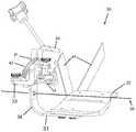
- FIG. 4is an isometric view of an orthosis of the present invention.
- FIG. 5is a front view of the orthosis of FIG. 4 ;
- FIG. 6is a side view of the orthosis of FIG. 4 ;
- FIG. 7is a sectional view of a drive assembly of the orthosis of FIG. 4 ;
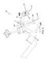
- FIG. 8is a section view of an adjustable second cuff for the orthosis of FIG. 4 .
- FIG. 9is a schematic diagram of an embodiment of an orthosis of the present invention.
- FIG. 10illustrates another embodiment of the invention utilizing a cushion or spring
- FIG. 11is an embodiment of the invention illustrating the use of a cam surface
- FIG. 12is an embodiment of the invention utilizing a slideable arcuate surface
- FIG. 13illustrates features of an orthosis of the invention where the relative positions of component parts of the orthosis are adjustable
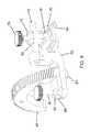
- FIG. 14is an illustration of the use of gears with an arcuate or cam surface of an orthosis of the invention.
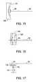
- FIG. 15is a schematic diagram of an embodiment of the invention using an arcuate path and gear or cam follower
- FIG. 16illustrates the use of a multi-slotted component to control movement of the orthosis
- FIG. 17illustrates an embodiment of the invention where linear movement of a component is translated into rotational and translational movement of another component of the orthosis.
- the present inventionrelates to an orthosis for causing a joint to flex or move through a range of motion.
- One exemplary application of an orthosis of the present inventionis in treatment of a toe of a patient's foot. While the invention is believed to provide significant improvements in this area of treatment, it may likewise be of benefit in treating other joints, such as ankles, knees, hips, fingers, wrists, elbows, shoulders, or the spine.
- Each toe in the footextends from the metatarsal bone and is formed by the proximal phalanx, middle phalanx, and distal phalanx, each of which is respectively pivotally connected to form a joint there between.
- the orthosis of the present inventionmay be configured to flex or extend (or both) a toe joint, where the joint defines an inner sector on the flexor side that decreases in angle as the joint is flexed (bent) and an outer sector on the extensor side that decreases in angle as the joint is extended (straightened).
- FIG. 1a schematic of the orthosis 10 of the present invention.
- the orthosis 10includes a first member 12 attachable to a first body portion, such as a user's foot.
- the shape and configuration of the first member 12may be selected to support or conform generally to a patient's foot.
- the first member 12may be a platform that contacts or supports the underside of a user's foot. Sidewalls or curved edges may be provided to help position, cradle, or securely hold the foot in proper position.
- the first member 12may have a profile or shape that generally conforms to a user's arch, shoe size, or foot width so that it fits more comfortably, holds the foot securely in place, or improves alignment of the device so that the range of motion imparted by the device corresponds to a joint's healthy range of motion.
- This conforming shape or profilemay be accomplished, for instance, by providing interchangeable platforms corresponding to different foot sizes and shapes.
- the interchangeable platformmay be selectively removed and replaced by an interchangeable platform of a different size.
- the first member 12may have adjustable surfaces that can be resized or repositioned to better support or correspond to a patient's foot.
- the overall length of the first member 12may be adjustable, or the width of the first member 12 near the toes may be adjusted to account for different foot widths.
- raised walls or edges that support the feetmay be selectively moveable so that they can be moved to accommodate different foot sizes. Once the foot is in place and the edges are moved to their desired position, they may be selectively locked or secured in place to help hold the foot in place.
- the first member 12may be configured with an arch, which in some instances also may be adjustable such as by having interchangeable arch inserts, by configuring the arch to be inflatable, or the like.
- the first member 12is operatively associated with or connected to a second member 14 so that the first and second members 12 and 14 may move or rotate with respect to each other.
- the supporting surface of the first member 12may be offset from the supporting surface of the second member 14 .
- This amount of offset providedmay vary from patient to patient or from joint to joint, and in some cases an offset may not be provided.
- the second member 14may be attachable to a second body portion, such as at least one toe on the foot so that the relative movement of the two members also causes movement of the joint.
- the orthosis 10may have an axis of rotation 16 that is aligned with the axis of rotation of the joint. In this manner, the instantaneous axis of rotation (IAR) of the first and second members 12 and 14 may better match the IAR of the treated joint. As will be discussed in greater detail below, while the axis of rotation 16 of the device is illustrated in FIGS.
- the axis of rotation 16may also shift or move depending on the relative positioning of the first and second members 12 and 14 in a manner that corresponds to changing axis of rotation that a joint may experience through its range of motion.
- the first and second members 12 and 14are operatively connected to each other, offset from the orthosis axis 16 .
- the first member 12 of the orthosis 10includes a first extension member 18 extending therefrom.
- the second member 14 of the orthosis 10includes a second extension member 20 extending therefrom and having an arcuate shape.
- the first and second extension members 18 and 20are operatively connected at point “P,” such that in operation the second extension member 20 travels along an arcuate path about and substantially through point “P.”
- the arcuate shape of the second extension member 20results in the toe rotating about the orthosis axis 16 , or alternatively about a moving IAR, when the second member 14 is moved from a first position to a second position relative to the first member 12 .
- the first extension member 18can extend substantially vertically from the first member 12 or extend at an angle ⁇ from the first member 12 .
- the angle ⁇ and the radius of curvature of the second extension member 20are configured such that of the orthosis axis 16 is aligned with the axis of rotation of the joint.
- first extension 18having a substantially linear shape, extending at an angle ⁇ from the first member 12 .
- first extension member 18can be any shape extending from the first member 12 which aligns orthosis axis 16 with the axis of rotation of the joint.
- the axis of rotation of the jointmay change or move slightly. Therefore, in some instances it may be desirable for the orthosis to mimic the IAR of the joint. As will be illustrated in detail below, this can be accomplished in several ways.
- One modification of the embodiment of the invention shown in FIG. 1may be for the second extension member 20 not to have a constant radius of curvature.
- the orthosis 10further includes a drive assembly 22 , which is illustrated in FIG. 1 at or near point “P.”
- the drive assembly 22is operably connected to the first and second extension members 18 and 20 for applying force to the first and second members 12 and 14 to pivot the second body portion about the orthosis axis 16 .
- the drive assembly 22may be configured or disposed to interact with or operate on one of the first or second members 12 and 14 independently.
- the first and second members 12 and 14may be affixed to the first and second body portions, respectively, tightly enough so that the first and second members 12 and 14 can apply torque to extend the joint.
- the second extension member 20is moved through the drive assembly 22 from a first position to a second position, relative to the first extension member 18 , rotating the second member 14 and the second body portion about the orthosis axis 16 stretching the joint.
- the second extension member 20travels at least partially through point “P” and may travel substantially through this point for a large range of motion.
- first and second members 12 and 14are affixed to the first and second body portions, the outward pivoting movement of the second member 14 causes the joint to be extended as desired.
- the orthosis 10may then be maintained in the second position for a predetermined treatment time providing a constant stretch to the joint.
- the orthosismay alternatively be configured to impart a constant force or load on the joint or may utilize the techniques of Static Progressive Stretch as described in co-pending application Ser. No. 11/203,516, entitled “Range of Motion System and Method”, and filed on Aug. 12, 2005, the entirety of which is incorporated by reference.
- the second member 14may then be moved back to the first position, relieving the joint.
- the second member 14can be rotated to a third position, increasing the stretch on the joint, or partially reducing it to allow limited relaxation of the surrounding tissue.
- the second member 14can be rotated at discrete time intervals to incrementally increase, reduce, or vary the stretch of the joint through the treatment cycle.
- the second arm 14is returned to the first position for removal of the orthosis 10 .
- first and second members 12 and 14are affixed to the first and second body portions, respectively, tightly enough so that the first and second members 12 and 14 can apply torque to extend the joint.
- a cuff, strap, laces, or other retaining devicemay be used to securely associate respective body portions of the joint with the first and second members 12 , 14 .
- the second extension member 20is moved through the drive assembly 22 from the first position to a second position, relative to the first extension member 18 , rotating the second member 14 and the second body portion about the orthosis axis 16 stretching the joint.
- the second extension member 20travels substantially through point “P.” Because the first and second members 12 and 14 are affixed to the first and second body portions, the inward pivoting movement of the second member 14 causes the joint to be flexed as desired.
- the orthosis 10is maintained in the second position for a predetermined treatment time providing a constant stretch to the joint.
- the second member 14After the expiration of the treatment time, the second member 14 is moved back to the first position, relieving the joint.
- the second member 14can be rotated to a third position, thereby increasing, decreasing, or otherwise varying the stretch on the joint.
- the second member 14can be rotated at discrete time intervals to incrementally increase the stretch of the joint through the treatment cycle.
- the second arm 14After completion of the treatment cycle, the second arm 14 is returned to the first position for removal of the orthosis 10 .
- FIGS. 4-6further illustrate several aspects of the invention more concretely.
- An orthosis 30 of the present inventionincludes a first member 31 having a first cuff 32 attachable to a user's foot and a second member 33 having a second cuff 34 attachable to a toe of the user's foot, wherein the second member 33 is rotatable with respect to the first member 31 about an axis of rotation 36 .
- the first and second members 31 and 33are attached to the foot and toe of the user with the first and second cuffs 32 and 34 , such that as the second member 33 is rotated about the axis of rotation 36 , the toe is rotated about a joint axis.
- a first extension member 38is affixed to and extends from the first member 31 , wherein a drive assembly 40 is positioned on an end portion of the first extension member 38 .
- a second extension member 42is similarly affixed to and extends from the second member 33 , wherein the second extension member 42 has an arcuate shape.
- the second extension member 42engages the drive assembly 40 of the first extension member 38 at a point “P.”
- An actuation of the drive assembly 40operates to move the second extension member 42 through the drive assembly 40 , such that the second cuff 34 travels along an arcuate path “A” with respect to the first member 31 .
- the arcuate shape of the second extension member 42results in the toe rotating about the joint axis, as the second cuff 34 is moved along the arcuate path “A.”
- the drive assembly 40can be actuated to move the second cuff 34 and toe from a first position to a second position relative to the first cuff 32 .
- the term “cuff” as used hereinmeans any suitable structure for transmitting the force of the orthosis 30 to the limb portion it engages.
- the first extension member 38can extend substantially vertically from the first member 31 or extend at an angle ⁇ from the first member 31 , where the angle ⁇ and the radius of curvature of the second extension member 42 (if constant) can be configured such that of the axis of rotation 36 is aligned with the joint axis of ration.
- the curvature of the second extension member 42need not be constant, and therefore the axis of rotation may shift or move in a manner that preferably mimics or approximates the moving IAR the joint would normally have.
- Another potential benefit of the orthosis 30 having the capability of a moving IARis when multiple joints are being treated by the device. For instance, the range of motion of the tip of a toe or finger may involve cooperative motion of two or more joints.
- the curvature of the second extension member 42may be complex in order to better approximate a moving IAR.
- the drive assembly 40can include a housing 50 having a worm gear 52 therein.
- a first miter gear 54is attached to the worm gear 52 such that a rotation of the first miter gear 54 rotates the worm gear 52 .
- the drive assembly 40further includes a drive shaft 56 have a knob 58 at one end and a second miter gear 60 at an opposite end.
- the second miter gear 60is positioned within the housing 50 , in engagement with the first miter gear 54 .
- a rotation of the knob 58rotates the drive shaft 56 and the second miter gear 60 , which in turn rotates the first miter gear 54 and the worm gear 52 .
- a gear surface 62 of the second extension member 42includes a plurality of teeth 64 .
- the second extension member 42is positioned throughout the housing 50 , such that the worm gear 52 engages the teeth 64 of the second extension member 42 .
- a rotation of the knob 58rotates the worm gear 52 , which in turn moves the second extension member 42 through the housing 50 .
- the drive assembly 40 for orthosis 30 in accordance with the present inventioncan be actuated by a motor instead of by a manually actuatable member, such as the knob 58 .
- the motormay be configured an adapted with gearing that causes the orthosis to cycle through a range of motion in a predetermined manner, or alternatively maybe controlled by a programmable logic controller (PLC).
- PLCprogrammable logic controller
- an electric motoris mounted to the drive shaft 56 for rotation of the second miter gear 60 .
- a battery or other source of energyprovides electric power to the motor.
- the motorcan be supplied with external power.
- a microprocessorcontrols the operation of the motor.
- the microprocessor and motor togethercan be used to cycle the second cuff 34 through a plurality of positions that cause the joint to undergo a range of motion, either by extension, by flexion, or both.
- the microprocessormay be used to move the second cuff 34 in one pivotal direction a certain amount, hold there while tissue stretches, then move further in that direction; or in any other manner.
- the orthosiscan be set to cycle to one end of the joint's range of motion and hold there for a predetermined period of time, then cycle to the other end of the joint's range of motion and hold there.
- the programming and control of the microprocessoris within the skill of the art as it relates to driving the motor to control the second cuff 34 to move in known manners.
- This embodimentis ideally suited for continuous passive motion exercise, because the orthosis is portable and because the motor can be programmed with the desired sequence of movements.
- the present inventioncan further include a monitor for use with the orthosis 30 , which provides assurances the patient is properly using the orthosis 30 during his/her exercise period
- the monitorcan have a position sensor, a temperature sensor, a force sensor, a clock or timer, or a device type sensor for monitoring the patient's implementation of a protocol.
- the information obtained from these monitoring devicesmay be stored for later analysis or confirmation of proper use or may be transmitted in real-time during use of the device.
- the data obtained from the monitorcan be analyzed by a healthcare professional or technician and the protocol can be adjusted accordingly.
- the orthosis 30is operated to rotate a toe about a joint axis in the following manner.
- the first cuff 32is fastened about the foot with one or more straps, laces, or similar retaining device.
- the second cuff 34is fastened securely to the toe of the user, such that the joint and joint axis 36 is interposed between the first and second cuffs 32 and 34 .
- the orthosis 30is attached to the foot and toe in a first position.
- the drive assembly 40is actuated to move the second extension member 42 , such that the second cuff 34 travels along an arcuate path from the first position to a second position, relative to the first cuff 32 , rotating the toe about the joint axis stretching the joint.
- the orthosis 30is maintained in the second position for a predetermined treatment time providing a constant stretch to the joint.
- the second cuff 34is moved back to the first position, relieving the joint.
- the second cuff 34can be rotated to a third position, thereby increasing or decreasing the stretch on the joint.
- the second cuff 34can be rotated at discrete time intervals to incrementally increase the stretch of the joint through the treatment cycle.
- the second arm memberis returned to the first position for removal of the orthosis 30 .
- the second member 33can include an attachment bracket 70 for adjustably attaching the second cuff 34 to the second extension member 42 .
- the attachment bracket 70can include a toe rod 72 extending therefrom.
- the second cuff 34can be slideably mounted on the toe rod 72 to position second cuff 34 over the toe.
- the toe rod 72can be of sufficient length such that the second cuff 34 can be slidingly positioned on a selected toe on the foot of the user, for example, the big toe, minimus toe, or any toe therebetween.
- the second cuff 34can be positioned on the toe rod 72 with a first bracket 74 , where the toe rod 72 passes through a passage 76 in the first bracket 74 .
- a set screw 78is provided to secure the first bracket 74 to the toe rod 72 . When the set screw 78 is loosened, the first bracket 74 is free to slide along the toe rod 72 . A tightening of the set screw 78 secures the first bracket 74 in place on the toe rod 72 .
- the second cuff 34can further include a second bracket 80 , where the second bracket 80 can be pivotally mounted to the first bracket 74 .
- the second bracket 80can be attached to the first bracket 74 with a pin or screw connector, allowing the second bracket 80 to rotate with respect to the first bracket 74 .
- a compressive forcemay be applied to the connective tissue surrounding the joint. It may be desirable to control the compressive force, distracting the joint as the joint is flexed or extended. “Distraction” is defined by one dictionary as “Separation of the surfaces of a joint by extension without injury or dislocation of the parts.” (Taber's Cyclopedic Medical Dictionary, 16th Edition, 1989, page 521), and involves stretching rather than compressing the joint capsule, soft tissue, ligaments, and tendons.
- the second bracket 80can be slideably mounted to the first bracket 74 .
- the second bracket 80can be mounted to the first bracket 74 with a dovetail joint 82 , allowing the second bracket 80 to slide with respect to the first bracket 74 .
- the sliding movement of the second cuff 34helps to limit the distractive or compressive forces which can be imparted on the joint by the rotation of the second cuff 34 with respect to the first cuff 32 .
- the attachment bracket 70can be pivotally mounted to the second extension member 42 .
- the attachment bracket 70can be attached to the second extension member 42 with a pin or screw connector 84 , allowing the attachment bracket 70 to rotate with respect to the second extension member 42 .
- the second extension member 42further includes a extension bracket 86 having a slotted portion 88 .
- a set screw 90is positionable through the slotted portion 88 , engaging the attachment bracket 70 , such that the set screw 90 can be used to control the pivotal position of the attachment bracket 70 with respect to the second extension member 42 .
- the adjustable connection of the second cuff 34 to the attachment bracket 70 and the pivotal connection of the attachment bracket 70 to the second extension member 42can be used to align the second cuff 34 with the toe.
- the alignment of the second cuff 34 on the toecan be used to substantially limit the force applied to the toe to that of a torque about the joint axis 36 .
- the orthosis 30In operation of the orthosis 30 to extend the joint, the orthosis starts at a more flexed position.
- the first and second cuffs 32 and 34are clamped onto the foot and toe portions, respectively, by straps 44 , tightly enough so that the first and second members 31 and 33 can apply torque to extend the joint.
- the second extension member 42is moved through the drive assembly 40 from the first position to a second position, relative to the first extension member 38 , rotating the second cuff 34 and the toe about the orthosis axis 36 stretching the joint.
- the second extension member 42travels along an arcuate path “A” about and substantially through point “P.”
- the orthosis 30is maintained in the second position for a predetermined treatment time providing a constant stretch to the joint.
- the second cuff 34moves along the first bracket 74 . Because the first and second members 31 and 33 are clamped onto the foot and toe as described above, the outward pivoting movement of the second cuff 34 causes the joint to be extended as desired. However, this extension of the joint can place strong distractive forces on the soft tissues around the joint. The sliding movement of the second cuff 34 helps to limit these distractive forces by counteracting the outward movement. Thus, the detrimental effects of strong distractive forces normally generated in forced extension of a joint are avoided, being replaced with the beneficial effects of limited and controlled distraction.
- the orthosis 30starts at a more extended position.
- the first and second cuffs 32 and 34are clamped onto the foot and toe portions, respectively, by straps 44 , tightly enough so that the first and second members 31 and 33 can apply torque to extend the joint.
- the second extension member 42is moved through the drive assembly 40 from the first position to a second position, relative to the first extension member 38 , rotating the second cuff 34 and the toe about the orthosis axis 36 stretching the joint.
- the second extension member 42travels along an arcuate path “A” about and substantially through point “P.”
- the orthosis 30is maintained in the second position for a predetermined treatment time providing a constant stretch to the joint.
- the second cuff 34moves along the first bracket 74 . Because the first and second members 31 and 33 are clamped onto the foot and toe as described above, the inward pivoting movement of the second cuff 34 causes the joint to be flexed as desired. However, this flexion of the joint can place strong compressive forces on the soft tissues around the joint. The sliding movement of the second cuff 34 helps to limit these compressive forces by counteracting the inward movement. Thus, the detrimental effects of strong compressive forces normally generated in forced flexion of a joint are avoided, being replaced with the beneficial effects of limited and controlled compression.
- FIG. 9schematically illustrates an embodiment of an orthosis 91 of the invention having a first member 92 and a second member 94 , both of which preferably having sufficient structure or component parts to hold body members near the treated joint or joints.
- the second memberhas a first pivoting contact point 96 about which the geared body member may rotate.
- the first pivoting contact 96does not move in relation to the first body member 92 , but as indicated in FIG. 10 one alternative embodiment may allow relative movement that can be resisted by a flexible device 106 such as a spring, compressed gas, foamed material, elastomer or the like.
- the second membermay have an additional pivot contact 98 , preferably disposed at a location at or near the opposite end of the second member 94 from where the first pivoting contact 96 is located.
- the second pivoting contact 98may be configured with a drive assembly 100 that causes the second member 94 to follow a predetermined path.
- the second pivoting contact 98 in the embodiment of FIG. 9is configured to move relative to the first member 92 in order to cause the joint to move from a first position to second one.
- the drive assembly 100 illustrated in FIG. 9is an arm or linkage 101 connected between the second pivot connection 98 and a rotating wheel 102 .
- the wheel 102may be configured so that the linkage 101 can be selectively connected to it in different radial distances from the center of rotation of the wheel. This allows the range of motion to be adjustable by the care provider, physician, or patient. As the wheel 102 is rotated, the linkage 101 moves in a manner that causes the second member 94 to move in a particular way.
- the second member 94(or alternatively the first member 92 ) may also have a sliding contact surface 104 .
- the sliding contact surface 104allows the joint to rotate or move according to its natural instantaneous axis of rotation. Thus, if the second pivot contact 98 moves in a manner that does not always exactly correspond to the axis of rotation of the joint, the sliding contact surface 104 may move or adjust accordingly.
- Another potential advantage of the sliding contact surface 104is that is may help facilitate proper alignment of the joint in the orthosis during initial setup.
- FIG. 10illustrates some variations that may also be used in orthosis of the invention.
- the first and or second pivot contactmay be configured with a cushion or spring 106 that allows one or both ends of the second member to impart some flexibility in the force imparted to the joint.
- the cushion or spring 106may be made of a variety of suitable materials and constructions to permit some flexibility in the movement of the pivot points 96 , 98 .
- the orthosis 91can be used in different treatment protocols than just by holding the joint in a prescribed location for a period of time.
- the orthosiscan utilize the principles of static progressive stretch as described in copending application Ser. No. 11/203,516, entitled “Range of Motion System and Method”, and filed on Aug. 12, 2005, the entirety of which is incorporated by reference.
- an orthosis 91 configured with a spring or cushion 106can be moved from an initial position to a second position that is determined not by position of the joint but instead by the amount of force the orthosis 91 imparts on the joint.
- the jointmay then be subjected to this loading, and over time as the surrounding tissue stretches the joint will move and the imparted forces will be reduced.
- FIG. 10illustrates the cushion or spring 106 associated with the first pivot contact 96 , it is not required to be associated with it. Instead, for example, the cushion or spring 106 may be associated with the second pivot 98 so that it can flex or move in response to resistive forces of the joint and nearby tissue. Likewise, there may be a spring or cushion 106 associated with both pivot contacts 96 , 98 .
- FIGS. 9 and 10Another notable variation between the embodiments of FIGS. 9 and 10 is that the rotating wheel 102 in FIG. 9 has multiple single point connections for connecting the linkage 101 at different distances from the center of rotation of the wheel.
- the embodiment of FIG. 10illustrates that an elongated slot 108 may be used to connect the linkage 101 .
- the advantage of utilizing multiple single point connectionsmay be ease of use and the ability to quickly confirm the orthosis 91 is properly configured for a prescribed treatment protocol, whereas one potential advantage of utilizing an elongated slot 108 is the ability to quickly adjust the settings without disassembling the device.
- FIG. 11illustrates an embodiment of the invention where the rotating wheel 102 is a cam surface 112 .
- This embodimentis similar to the use of cams and followers as described in U.S. Pat. No. 5,514,143, which is incorporated herein in its entirety.
- the cam surface 112may have varying distance from the center or rotation of the wheel 102 . If the wheel 102 is circular, for example, the center of rotation may be located somewhere different from the geometric center of the circle or at the center or rotation of the shape. As it rotates, the circumferential outer surface causes the linkage 101 to move to the second member 98 in a desired manner. Additionally, the outer edge of the “wheel” 102 need not be round, but instead may be a cam surface 112 of varying distance from the center or rotation. Likewise, the outer surface may have varying radii of curvature as shown in FIG. 11 .
- FIGS. 12 and 13further illustrate that a cam surface 112 may be used to move the second member 92 in a desired, perhaps complex way. As is the case for other embodiments described herein, performance of the cam surface 112 may be enhanced because of the ability to better mimic or replicate a moving axis of rotation of the treated tissue and joint.
- the cam surface 112is associated with the first member 92 .
- Linkages or arms 101 of the second member 94have cam followers 113 that trace the cam surface 112 and cause the second member 94 to move in a more complex manner than just by rotation around a fixed axis.
- the cam surface 112 of FIG. 12also is associated with a slot 100 that allows the relative location of the first and second members 92 and 94 to be adjusted or moved without decoupling the cam followers 113 from the cam surface 112 .
- the slot 110allows for horizontal adjustment repositioning.
- vertical slotsmay also be provided, either alone or in combination with a horizontal slot.
- FIG. 13illustrates an example where the linkage 100 is a cam surface 112 that passes through two or more points 114 , 116 that are stationary or fixed relative to the first member 92 when the orthosis 91 is in use (i.e. after alignment is completed).
- this embodimentmay be configured to permit horizontal adjustment, such as by providing slot 110 , and likewise may be configured to be vertically adjustable.
- this embodimentalso illustrates that the first and second members 92 and 94 may be represented by rotation about a pivot 118 .
- the use of horizontal, vertical, and rotational adjustment of the relative positions of the first and second members 92 and 94may allow greater fitting of the orthosis 91 to the treated tissue and joint.
- FIG. 14is an exploded view of how the cam surface 112 and cam followers 113 may utilize a geared surface 120 . Utilizing a geared surface 120 may allow for a drive assembly 100 to automate the movement of the orthosis 91 .
- FIGS. 15 and 16schematically illustrate other ways in which potentially complex movement of the second member 94 may be controlled.
- FIG. 15illustrates that the cam surface may not be directly formed from a component part of either the first or second members, but instead maybe associated with some other structure.
- the orthosis 91may be operatively connected to a base unit 122 having a plurality of cam surfaces 124 corresponding to different ranges of motion for related joints, such as when the orthosis 91 can be used to treat a plurality of different toes or a patient. Once the orthosis 91 is placed on the patient, the second member 94 will be positioned to securely hold one of the toes on the patient's foot and to engage with the cam surface 124 corresponding to that toe.
- FIG. 16shows that multiple cam surfaces or slots 126 may be formed in a side panel 128 .
- the side panel 128may have a sliding engagement of the second member 94 . As the second member 94 moves, the engagement with the side panel 128 controls position and movement.
- one or more sides or edges of a slot 126 of the embodiment of FIG. 16may be geared to allow implementation of a drive assembly 100 .
- FIG. 17illustrates an embodiment where movement of at least part of a linkage 101 may be linear, but when combined with a rotational pivot 130 , sliding slot 132 , and possibly other components or combinations described herein, the net effect on the second member 94 is once again a controlled movement in a desired manner.
- the components of the present inventionare rigid members made of, for example, aluminum, stainless steel, polymeric, or composite materials.
- the member and extensionsare sufficiently rigid to transmit the necessary forces. It should be understood that any material of sufficient rigidity might be used.
- some componentscan be made by injection molding. Generally, for injection molding, tool and die metal molds of the components are prepared. Hot, melted plastic material is injected into the molds. The plastic is allowed to cool, forming components. The components are removed from the molds and assembled.
- the componentscan be made of polymeric or composite materials such that the device can be disposable.
- the componentscan be made of a biodegradable material such as a biodegradable polymer.
- a biodegradable materialsuch as a biodegradable polymer.
- PHA'spoly (hydroxyacids)
- PLApolyactic acid
- PGApolyglycolic acid
- the devicecan be made of a nonmagnetic material.
- the devicecan be used as a positioning device for use in imaging devices, such as a MRI device. It is also contemplated that the device can be used as a positioning device for use during surgical procedures, where it may be necessary to adjust and hold the position of the joint.
Landscapes
- Health & Medical Sciences (AREA)
- Epidemiology (AREA)
- Pain & Pain Management (AREA)
- Physical Education & Sports Medicine (AREA)
- Rehabilitation Therapy (AREA)
- Life Sciences & Earth Sciences (AREA)
- Animal Behavior & Ethology (AREA)
- General Health & Medical Sciences (AREA)
- Public Health (AREA)
- Veterinary Medicine (AREA)
- Orthopedics, Nursing, And Contraception (AREA)
- Prostheses (AREA)
Abstract
Description
Claims (12)
Priority Applications (1)
| Application Number | Priority Date | Filing Date | Title |
|---|---|---|---|
| US15/295,588US10456314B2 (en) | 2005-10-28 | 2016-10-17 | Range of motion device |
Applications Claiming Priority (4)
| Application Number | Priority Date | Filing Date | Title |
|---|---|---|---|
| US11/261,424US8066656B2 (en) | 2005-10-28 | 2005-10-28 | Range of motion device |
| US13/305,020US8287479B2 (en) | 2005-10-28 | 2011-11-28 | Range of motion device |
| US13/651,936US9468578B2 (en) | 2005-10-28 | 2012-10-15 | Range of motion device |
| US15/295,588US10456314B2 (en) | 2005-10-28 | 2016-10-17 | Range of motion device |
Related Parent Applications (1)
| Application Number | Title | Priority Date | Filing Date |
|---|---|---|---|
| US13/651,936ContinuationUS9468578B2 (en) | 2005-10-28 | 2012-10-15 | Range of motion device |
Publications (2)
| Publication Number | Publication Date |
|---|---|
| US20170100297A1 US20170100297A1 (en) | 2017-04-13 |
| US10456314B2true US10456314B2 (en) | 2019-10-29 |
Family
ID=37997444
Family Applications (4)
| Application Number | Title | Priority Date | Filing Date |
|---|---|---|---|
| US11/261,424Active2026-01-16US8066656B2 (en) | 2004-03-08 | 2005-10-28 | Range of motion device |
| US13/305,020ActiveUS8287479B2 (en) | 2005-10-28 | 2011-11-28 | Range of motion device |
| US13/651,936Active2027-01-18US9468578B2 (en) | 2005-10-28 | 2012-10-15 | Range of motion device |
| US15/295,588Active2027-01-06US10456314B2 (en) | 2005-10-28 | 2016-10-17 | Range of motion device |
Family Applications Before (3)
| Application Number | Title | Priority Date | Filing Date |
|---|---|---|---|
| US11/261,424Active2026-01-16US8066656B2 (en) | 2004-03-08 | 2005-10-28 | Range of motion device |
| US13/305,020ActiveUS8287479B2 (en) | 2005-10-28 | 2011-11-28 | Range of motion device |
| US13/651,936Active2027-01-18US9468578B2 (en) | 2005-10-28 | 2012-10-15 | Range of motion device |
Country Status (1)
| Country | Link |
|---|---|
| US (4) | US8066656B2 (en) |
Cited By (1)
| Publication number | Priority date | Publication date | Assignee | Title |
|---|---|---|---|---|
| US20220175567A1 (en)* | 2006-03-20 | 2022-06-09 | Bonutti Research, Inc. | Elbow Orthosis |
Families Citing this family (20)
| Publication number | Priority date | Publication date | Assignee | Title |
|---|---|---|---|---|
| US6113562A (en) | 1998-06-01 | 2000-09-05 | Peter M. Bonutti | Shoulder orthosis |
| US6502577B1 (en) | 2000-09-18 | 2003-01-07 | Peter M. Bonutti | Method for moving finger joints |
| US6503213B2 (en) | 2000-12-01 | 2003-01-07 | Peter M. Bonutti | Method of using a neck brace |
| US6575926B2 (en) | 2000-12-15 | 2003-06-10 | Bonutti 2003 Trust-A | Myofascial strap |
| US7452342B2 (en) | 2004-03-08 | 2008-11-18 | Bonutti Research Inc. | Range of motion device |
| US8066656B2 (en) | 2005-10-28 | 2011-11-29 | Bonutti Research, Inc. | Range of motion device |
| US8012108B2 (en) | 2005-08-12 | 2011-09-06 | Bonutti Research, Inc. | Range of motion system and method |
| US8920346B2 (en) | 2007-02-05 | 2014-12-30 | Bonutti Research Inc. | Knee orthosis |
| EP2178475A1 (en) | 2007-07-25 | 2010-04-28 | Bonutti Research Inc. | Orthosis apparatus and method of using an orthosis apparatus |
| US8905950B2 (en) | 2008-03-04 | 2014-12-09 | Bonutti Research, Inc. | Shoulder ROM orthosis |
| CN103158081B (en)* | 2011-12-12 | 2015-01-28 | 鸿富锦精密工业(深圳)有限公司 | Clamping adjusting device and rotating adjusting mechanism thereof |
| FR2991224B1 (en)* | 2012-06-04 | 2014-06-27 | Commissariat Energie Atomique | ARM OF EXOSQUELET WITH ACTUATOR |
| US9402759B2 (en) | 2013-02-05 | 2016-08-02 | Bonutti Research, Inc. | Cervical traction systems and method |
| DE102013108701A1 (en)* | 2013-08-12 | 2015-02-12 | Franz Freuler | therapy device |
| US10420691B2 (en) | 2016-02-24 | 2019-09-24 | Richard Stewart | Knee range of motion device utilizing tangential joint translation and distraction |
| EP3357474A1 (en)* | 2017-02-07 | 2018-08-08 | Fundación Tecnalia Research & Innovation | Rehabilitation device for a joint |
| US11844738B2 (en) | 2018-08-17 | 2023-12-19 | Troy Bruesewitz | Therapy device for neck and spine |
| CN109124987B (en)* | 2018-09-12 | 2020-11-13 | 衢州学院 | A fully automatic ankle full range of activities and weight-bearing rehabilitation device |
| WO2020118348A1 (en)* | 2018-12-12 | 2020-06-18 | VFAS International Holdings Pty Ltd | Foot and ankle surgical method and apparatus therefor |
| CN109481132B (en)* | 2018-12-21 | 2021-03-23 | 上海市东方医院 | A kind of rheumatoid arthritis nursing device and nursing method thereof |
Citations (286)
| Publication number | Priority date | Publication date | Assignee | Title |
|---|---|---|---|---|
| US432327A (en) | 1890-07-15 | William i | ||
| US433227A (en) | 1890-07-29 | Thirds to charles it | ||
| DE405327C (en) | 1924-03-19 | 1924-10-31 | Fritz Groenert | Stretching device to remedy shortened tendons |
| US2191283A (en) | 1938-07-02 | 1940-02-20 | Harry H Leiter | Splint |
| US2206902A (en) | 1935-04-29 | 1940-07-09 | Kost Alwin | Foot corrective device |
| US2223276A (en) | 1937-12-17 | 1940-11-26 | Thomas C Ward | Cervical splint |
| US2237252A (en) | 1939-09-27 | 1941-04-01 | Harry Herschel Leiter | Surgical arm rest and support therefor |
| US2246689A (en) | 1938-05-09 | 1941-06-24 | Kost Alwin | Mechanical movement |
| US2250493A (en) | 1940-06-10 | 1941-07-29 | George M Milne | Foot and leg exercising device |
| US2395936A (en) | 1944-10-12 | 1946-03-05 | Oleisky Isadore | Posture correcting device |
| US2590729A (en) | 1948-06-16 | 1952-03-25 | Scognamillo Engineering Compan | Rotary compressor |
| US2590739A (en) | 1949-07-26 | 1952-03-25 | Wagner Hugo | Orthopedic bone aligning and fixing mechanism |
| US2811154A (en) | 1953-07-20 | 1957-10-29 | William M Scholl | Stretchable bandage |
| US2820455A (en) | 1953-12-28 | 1958-01-21 | Newton J Hall | Neck brace |
| US2829562A (en) | 1953-02-03 | 1958-04-08 | Rue Richard M La | Cartridge feeding mechanism |
| US2832334A (en) | 1956-05-23 | 1958-04-29 | Stephen H Whitelaw | Therapeutic device for use in manipulative treatment of joints of the human body |
| US2844038A (en)* | 1955-05-04 | 1958-07-22 | Hoffman Electronics Corp | Bi-directional mechanical limit stop system or the like |
| US3083708A (en) | 1960-08-08 | 1963-04-02 | Jobst Institute | Sleeve or legging for stimulating flow of fluids within an animal body |
| US3338237A (en) | 1964-10-20 | 1967-08-29 | Sconce Jerry Wayne | Pneumatic splint |
| US3351055A (en) | 1963-11-26 | 1967-11-07 | Jobst Institute | Pressure bandage-splint and method of forming same |
| US3548818A (en) | 1968-03-14 | 1970-12-22 | David Kaplan | Shoulder brace |
| US3580248A (en) | 1968-12-02 | 1971-05-25 | Leighton W Larson | Bivalved cast |
| US3698389A (en) | 1971-05-21 | 1972-10-17 | Guedel Co Inc | Elbow locking device |
| US3701349A (en) | 1971-05-13 | 1972-10-31 | Leighton W Larson | Bi-valved cast |
| US3724452A (en) | 1971-03-04 | 1973-04-03 | Green T | Cervical brace |
| US3760056A (en) | 1970-09-23 | 1973-09-18 | Bogert R | Method for custom fitting an inflatable bladder to a wearer{3 s foot |
| US3795243A (en) | 1973-01-29 | 1974-03-05 | J Miller | Ambulatory traction device for cervical problems |
| US3811434A (en) | 1972-10-26 | 1974-05-21 | Jacobson S Mfg | Inflatable splint |
| US3814419A (en) | 1973-06-04 | 1974-06-04 | L Bjorklund | Arm exercising device |
| US3832997A (en) | 1972-08-30 | 1974-09-03 | Lambda Dev Ltd | Orthopedic device for combination with a plaster cast |
| US3856004A (en) | 1973-12-26 | 1974-12-24 | Comfort Care Prod | Clavicle brace |
| US3955565A (en) | 1973-12-05 | 1976-05-11 | Johnson Jr Glenn W | Orthopedic apparatus |
| US3970316A (en) | 1975-03-27 | 1976-07-20 | Diversified Products, Inc. | Golf swing restrictor |
| US3976057A (en) | 1974-12-23 | 1976-08-24 | Clarence F. Bates | Joint flexing apparatus |
| US4076022A (en) | 1976-12-20 | 1978-02-28 | James Walker | Therapeutic foot and leg protector |
| US4084267A (en) | 1975-09-18 | 1978-04-18 | Viennatone Gesellschaft M.B.H. | Drive for an orthosis or a prosthesis |
| US4108170A (en) | 1977-03-24 | 1978-08-22 | Spann Donald C | Patient support strap |
| US4180870A (en) | 1975-04-15 | 1980-01-01 | Fa Wilh. Jul. Teufel | Universal-orthese |
| DE2829562A1 (en) | 1978-07-05 | 1980-01-17 | Klaus Muenich | Machine for exercising part of human body - has motor reversing switch actuated by lever coupled to winch drum |
| US4214577A (en) | 1978-02-27 | 1980-07-29 | Hoy Mansell I | Orthosis for exercising joint |
| US4229001A (en) | 1979-02-23 | 1980-10-21 | Roman Michael P | Therapeutic exercise device |
| US4237873A (en) | 1978-12-11 | 1980-12-09 | Hoyt Laurance J Sr | Cerebral palsy arm and hand brace |
| US4241731A (en) | 1978-05-11 | 1980-12-30 | Pauley James H | Universal arm support |
| US4273113A (en) | 1979-10-29 | 1981-06-16 | World Medical Marketing Corporation | Foot exerciser |
| US4285773A (en) | 1977-08-27 | 1981-08-25 | Alberta Oil Sands Technology And Research Authority | Apparatus and process for recovery of hydrocarbon from inorganic host materials |
| US4310154A (en) | 1980-04-21 | 1982-01-12 | Kauffman Peter T | Exercising device for the fingers, wrist and forearm |
| US4320748A (en) | 1980-11-20 | 1982-03-23 | Orthomedics, Inc. | Fracture brace |
| US4363481A (en) | 1980-11-20 | 1982-12-14 | Erickson David T | Exercise device |
| US4370977A (en) | 1981-05-04 | 1983-02-01 | Kenneth D. Driver | Knee and elbow brace |
| US4383523A (en) | 1980-06-13 | 1983-05-17 | Schurman John R | Cervical brace |
| US4417569A (en) | 1981-10-19 | 1983-11-29 | Alexander Mencher | Universal functional shoulder orthosis |
| US4441489A (en) | 1981-03-10 | 1984-04-10 | National Research Development Corporation | Orthopaedic splints |
| US4454871A (en) | 1980-09-29 | 1984-06-19 | Med-Con, Inc. | Ankle-foot orthosis |
| US4456002A (en) | 1982-09-27 | 1984-06-26 | L M B Hand Rehab Products | Spring metacarpophalangeal flexion splint (knuckle splint) |
| US4456001A (en) | 1982-07-02 | 1984-06-26 | Electro-Biology, Inc. | Apparatus for equine hoof treatment |
| US4502470A (en) | 1982-09-16 | 1985-03-05 | Kiser John L | Physiologic device and method of treating the leg extremities |
| US4502681A (en) | 1980-08-08 | 1985-03-05 | Olle Blomqvist | Apparatus for carrying out quadriceps training |
| US4508111A (en) | 1981-07-23 | 1985-04-02 | Dynasplint Systems, Inc. | Adjustable splint |
| US4509509A (en) | 1983-07-11 | 1985-04-09 | Jean Bouvet | Apparatus for treating the joints of the human body |
| SU1158195A1 (en) | 1983-09-20 | 1985-05-30 | 9-Я Городская Клиническая Больница Г.Запорожья | Apparatus for developing contractures of upper limb |
| US4538600A (en) | 1983-10-27 | 1985-09-03 | Dynasplint Systems, Inc. | Adjustable splint |
| US4538595A (en) | 1984-02-21 | 1985-09-03 | Hajianpour Muhamad A | Passive exercising device |
| US4558692A (en) | 1984-06-25 | 1985-12-17 | Greiner Donn B | Passive leg exerciser |
| US4570619A (en) | 1982-10-27 | 1986-02-18 | Jung Corporation | Clavicle brace |
| US4576151A (en) | 1984-03-19 | 1986-03-18 | Carmichael Hoagy C | Orthopedic leg appliance |
| US4589406A (en) | 1983-08-11 | 1986-05-20 | Florek Florian F | Orthopaedic appliance for use in treating acromioclavicular joint injuries |
| EP0181688A2 (en) | 1984-10-30 | 1986-05-21 | SEGAL, David | Limb exerciser |
| EP0181668A1 (en) | 1984-11-02 | 1986-05-21 | North American Philips Corporation | Method and apparatus for measuring the apparent frequency shift of ultrasound pulses in tissue |
| US4612919A (en) | 1984-10-03 | 1986-09-23 | Best Walter E | Adjustable limb support |
| US4628913A (en) | 1984-01-13 | 1986-12-16 | United States Manufacturing Co. | Cervical thoracic orthosis |
| US4641639A (en) | 1985-12-09 | 1987-02-10 | Rigoberto Padilla | Ambulatory brace assembly |
| US4653479A (en) | 1985-01-17 | 1987-03-31 | Empi, Inc. | Interrupted drive limb motion apparatus |
| US4665905A (en) | 1986-06-09 | 1987-05-19 | Brown Charles S | Dynamic elbow and knee extension brace |
| US4693239A (en) | 1986-01-21 | 1987-09-15 | Orthomedics, Inc. | Orthosis |
| US4716889A (en) | 1981-10-23 | 1988-01-05 | Toronto Medical Corp. | Device for imparting continuous passive motion to human joints |
| US4718665A (en) | 1986-07-15 | 1988-01-12 | Soma Dynamics Corporation | Exercise device |
| US4727865A (en) | 1985-03-07 | 1988-03-01 | Hill Byrne Christopher R | Replaceable rigid cast with integral fasteners |
| US4739334A (en) | 1986-09-30 | 1988-04-19 | The United States Of America As Represented By The Secretary Of The Air Force | Electro-optical beamforming network for phased array antennas |
| DE8806231U1 (en) | 1988-05-11 | 1988-06-23 | Heinrich Caroli KG, 7630 Lahr | Double joint splint for treatment after knee surgery |
| WO1988004543A1 (en) | 1984-06-15 | 1988-06-30 | Spademan Richard George | Self-adjusting cuff device |
| US4765320A (en) | 1987-05-11 | 1988-08-23 | Smith & Nephew Rolyan, Inc. | Dynamic low profile splint |
| SU1426580A1 (en) | 1987-02-04 | 1988-09-30 | Научно-исследовательский институт травматологии и ортопедии | Arrangement for mechanotherapy of fingers of the hand |
| US4788941A (en) | 1987-05-14 | 1988-12-06 | Villeneuve Gerald P | Safety belt |
| US4790301A (en) | 1987-10-23 | 1988-12-13 | Krister Silfverskiold | Device for and method of dynamic splinting |
| US4793334A (en) | 1986-07-22 | 1988-12-27 | Mcguinness Charles G | Cervical brace |
| US4805601A (en) | 1985-03-15 | 1989-02-21 | Eischen Sr Clement G | Device for lower limb extremity having weight-response pressure chambers |
| US4809688A (en) | 1986-04-22 | 1989-03-07 | Empresa Cubana Importadora Y. Exportadora Of Products Medicos, T/A Medicuba | Sinergic splint for early mobilization of the flexor tendons of the hand |
| US4834073A (en) | 1987-02-20 | 1989-05-30 | Medical Technology, Inc. | Passive motion exerciser |
| US4844094A (en) | 1987-05-29 | 1989-07-04 | Royce Medical Company | Ankle brace |
| US4844455A (en) | 1987-12-21 | 1989-07-04 | Har-Tru Corporation | Tennis net tightening apparatus |
| US4844454A (en) | 1988-07-15 | 1989-07-04 | Rogers Stephen A | Portable, manually operable knee exerciser |
| US4848326A (en) | 1988-06-20 | 1989-07-18 | Robert Lonardo | Knee contracture correction device |
| US4862877A (en) | 1987-11-18 | 1989-09-05 | Lmb Hand Rehab Products, Inc. | Hand splint for wrist support with optional support of MP joints and thumb and IP finger assists |
| US4865024A (en) | 1988-10-21 | 1989-09-12 | Hensley Dvid E | Extension deceleration orthosis |
| US4869267A (en) | 1988-05-10 | 1989-09-26 | Royce Medical Company | Adjustable tension ankle support |
| US4869499A (en) | 1989-01-17 | 1989-09-26 | Schiraldo Donald R | Toe exercise device |
| US4884454A (en) | 1988-11-14 | 1989-12-05 | Lifting Technologies, Inc. | Manbasket testing apparatus and method |
| US4913755A (en) | 1988-03-16 | 1990-04-03 | Royce Medical Company | Method of forming orthopaedic gel pads |
| US4913135A (en) | 1986-12-16 | 1990-04-03 | Mattingly Leslie G | Cervical brace |
| US4930497A (en) | 1989-01-23 | 1990-06-05 | Toronto Medical Corp. | Apparatus for imparting continuous passive motion to a lower limb |
| EP0380060A2 (en) | 1989-01-24 | 1990-08-01 | Robert D. Singer | Electronic range of motion apparatus for orthosis, prothesis and CPM machine |
| US4953543A (en) | 1988-08-09 | 1990-09-04 | Royce Medical Company | Cruciate ligament leg brace |
| US4955396A (en) | 1988-02-05 | 1990-09-11 | Northwest Marine Technology, Inc. | Method for tagging macro-organisms |
| US4955369A (en) | 1988-10-27 | 1990-09-11 | Bledsoe Gary R | Dynamically shiftable counter shear force knee brace |
| US4957281A (en) | 1989-01-30 | 1990-09-18 | Wright State University | Rotator cuff therapeutic exercise apparatus |
| US4964402A (en) | 1988-08-17 | 1990-10-23 | Royce Medical Company | Orthopedic device having gel pad with phase change material |
| US4991234A (en) | 1989-10-10 | 1991-02-12 | Bert Greenberg | Body support band |
| US4996979A (en) | 1989-10-13 | 1991-03-05 | Royce Medical Company | Soft-goods type, formable orthopaedic cast |
| US5005563A (en) | 1990-06-18 | 1991-04-09 | Veale Charles J | Mobile-cervical extension and supporting apparatus |
| US5018514A (en) | 1987-06-11 | 1991-05-28 | Brace Technologies, Inc. | Knee brace |
| US5019050A (en) | 1989-05-30 | 1991-05-28 | Lynn Karen K | Securing device and method |
| US5025782A (en) | 1990-02-12 | 1991-06-25 | Ambulatory Traction Inc. | Adjustable rack and pinion knee brace |
| US5027801A (en) | 1987-05-29 | 1991-07-02 | Royce Medical Company | Orthopaedic gel pad assembly |
| US5027802A (en) | 1989-06-16 | 1991-07-02 | Donohue Patrick T | Multi-mode digital traction system |
| US5027688A (en) | 1988-05-18 | 1991-07-02 | Yamaha Corporation | Brace type angle-detecting device for musical tone control |
| US5036838A (en) | 1990-07-16 | 1991-08-06 | Applied Technology International, Ltd. | Foam plastic orthopedic fabric |
| US5036837A (en) | 1990-02-09 | 1991-08-06 | Bio-Tec, Inc. | Dynamic extension splint |
| SU1671296A1 (en) | 1988-11-21 | 1991-08-23 | Ленинградский научно-исследовательский детский ортопедический институт им.Г.И.Турнера | Orthopedic appliance for upper limb |
| US5052379A (en) | 1989-04-27 | 1991-10-01 | Soma Dynamics Corporation | Combination brace and wearable exercise apparatus for body joints |
| US5052375A (en) | 1990-02-21 | 1991-10-01 | John G. Stark | Instrumented orthopedic restraining device and method of use |
| FR2661333A1 (en) | 1990-04-25 | 1991-10-31 | Caruana Patrick | Muscle exercise apparatus with multiple articulations |
| US5070866A (en) | 1990-10-25 | 1991-12-10 | Alexander William K | Woven back support belt with rigidity control |
| US5078128A (en) | 1990-06-27 | 1992-01-07 | Royce Medical Company | Removable leg walker |
| US5088481A (en) | 1990-10-10 | 1992-02-18 | Darco International Inc. | Casted foot medical boot with dual pivot points |
| US5100403A (en) | 1990-06-08 | 1992-03-31 | Smith & Nephew Richards, Inc. | Dynamic elbow support |
| US5102411A (en) | 1990-06-08 | 1992-04-07 | Hotchkiss Robert N | Dynamic elbow support |
| US5116359A (en) | 1990-12-05 | 1992-05-26 | Moore Joseph L | Head, neck and shoulder therapeutic exercise device |
| US5125400A (en) | 1985-12-16 | 1992-06-30 | Aircast Incorporated | Ankle brace having multiple inflatable aircells |
| US5135470A (en) | 1988-05-25 | 1992-08-04 | Bryan Reeves | Shoulder and back support brace |
| US5139475A (en) | 1990-08-14 | 1992-08-18 | Francis Robicsek | Medical appliance for treating venous insufficiency |
| US5141489A (en) | 1991-07-26 | 1992-08-25 | Sereboff Joel L | Cervical brace |
| CA2066151A1 (en) | 1991-04-17 | 1992-10-18 | Peter M. Bonutti | Orthosis with joint distraction |
| EP0510840A1 (en) | 1991-04-24 | 1992-10-28 | Peter M. Bonutti | Orthosis with distraction through range of motion |
| US5163451A (en) | 1990-12-19 | 1992-11-17 | Sutter Corporation | Rehabilitation patient positioning method |
| US5167612A (en) | 1990-07-30 | 1992-12-01 | Bonutti Peter M | Adjustable orthosis |
| US5191903A (en) | 1991-06-06 | 1993-03-09 | Donohue Patrick T | Digital traction system |
| US5197942A (en) | 1992-01-13 | 1993-03-30 | Harold Brady | Customized foot orthosis |
| US5201702A (en) | 1990-04-17 | 1993-04-13 | Mars Suzanne P | Brace for supporting the head in an upright position |
| US5201772A (en) | 1991-01-31 | 1993-04-13 | Maxwell Scott M | System for resisting limb movement |
| US5203321A (en) | 1990-12-11 | 1993-04-20 | Sutter Corporation | Passive anatomic ankle-foot exerciser |
| US5211161A (en) | 1991-01-22 | 1993-05-18 | Compagnie Generale De Materiel Orthopedique | Three axis passive motion exerciser |
| US5213095A (en) | 1991-02-06 | 1993-05-25 | Dague Lawrence M | Coupling apparatus for scuba gear |
| US5218954A (en) | 1992-07-09 | 1993-06-15 | Bemmelen Paul S Van | Arterial assist device and method |
| US5226245A (en) | 1991-09-20 | 1993-07-13 | Lamont William D | Protective boot structure |
| US5232435A (en) | 1992-02-04 | 1993-08-03 | Saul Leibinsohn | Splint |
| US5252102A (en) | 1989-01-24 | 1993-10-12 | Electrobionics Corporation | Electronic range of motion apparatus, for orthosis, prosthesis, and CPM machine |
| US5252101A (en) | 1992-01-24 | 1993-10-12 | Breslow, Morrison, Terzian & Associates, Inc. | Simulated toy commode |
| US5261125A (en) | 1992-01-08 | 1993-11-16 | Rudolph Cartwright | Head impact force diversion system |
| US5277695A (en) | 1991-11-08 | 1994-01-11 | Aircast, Inc. | Adjustable ankle compress |
| US5297540A (en) | 1992-01-29 | 1994-03-29 | Jace Systems, Inc. | Continuous passive motion orthosis device for a toe |
| US5312322A (en) | 1992-11-02 | 1994-05-17 | The United States Of America As Represented By The Secretary Of The Navy | Three point extension splint to treat flexion contractures about limb synovial hinge joints |
| US5316022A (en) | 1992-08-28 | 1994-05-31 | Schiek Sr James W | Sports belt with cinchable fastener system |
| US5323435A (en) | 1993-07-16 | 1994-06-21 | Combustion Engineering Inc. | Control rod housing support bars with wing assemblies |
| US5328448A (en) | 1993-03-16 | 1994-07-12 | Gray Sr Richard O | Finger joint therapy apparatus |
| US5327882A (en) | 1992-09-03 | 1994-07-12 | Toronto Medical Corp. | Continuous passive motion device |
| USRE34661E (en) | 1988-05-10 | 1994-07-12 | Royce Medical Company | Gel and air cushion ankle brace |
| US5329705A (en) | 1993-02-16 | 1994-07-19 | Royce Medical Company | Footgear with pressure relief zones |
| US5348530A (en) | 1993-07-29 | 1994-09-20 | Royce Medical Company | Pneumatic ankle brace with bladder and pump arrangement |
| US5349956A (en) | 1991-12-04 | 1994-09-27 | Apogee Medical Products, Inc. | Apparatus and method for use in medical imaging |
| US5352216A (en) | 1989-10-26 | 1994-10-04 | Alcare Co., Ltd. | Stretch fabric for medical use |
| US5354260A (en) | 1993-05-13 | 1994-10-11 | Novamedix, Ltd. | Slipper with an inflatable foot pump |
| US5364323A (en) | 1993-09-09 | 1994-11-15 | Tony Liu | Multi-directional rotatable wrist exerciser |
| US5370133A (en) | 1994-02-22 | 1994-12-06 | Darco International, Inc. | Lower leg, ankle and foot immobilization brace with uniform, adjustable compression |
| US5372597A (en) | 1993-05-12 | 1994-12-13 | Smith & Nephew Richards, Inc. | Supination-pronation device |
| US5376091A (en) | 1990-06-08 | 1994-12-27 | Smith & Nephew Richards, Inc. | Dynamic finger support |
| US5378223A (en) | 1992-10-23 | 1995-01-03 | Royce Medical Company | Orthopedic support pad and method for providing semi-permanent relief zones |
| US5385536A (en) | 1993-03-01 | 1995-01-31 | Wayne Z. Burkhead | Orthopedic brace for arm and shoulder |
| US5389065A (en) | 1993-06-15 | 1995-02-14 | Aircast, Inc. | Ankle brace with ATF compression |
| US5391132A (en) | 1992-09-16 | 1995-02-21 | Greenwald; Dale R. | Free standing rotator cuff development device |
| US5399152A (en) | 1990-09-13 | 1995-03-21 | Habermeyer; Peter | Apparatus for treating fractures in extremities |
| US5403265A (en) | 1993-11-03 | 1995-04-04 | Lunax Corporation | Pressure sock |
| US5407422A (en) | 1994-10-04 | 1995-04-18 | Sharon C. Hanson | Pelvic belt |
| US5407420A (en) | 1992-11-12 | 1995-04-18 | Smith & Nephew Donjoy, Inc. | Fully adjustable shoulder brace |
| US5417643A (en) | 1993-10-27 | 1995-05-23 | Danninger Medical Technology, Inc. | Continuous passive motion exercise device |
| US5419757A (en) | 1992-12-28 | 1995-05-30 | Daneshvar; Yousef | Support containing shaped balloons |
| US5421874A (en) | 1993-06-22 | 1995-06-06 | Genesis Composites, L.C. | Composite microsphere and lubricant mixture |
| US5435009A (en) | 1992-10-01 | 1995-07-25 | Huntleigh Technology Plc | Inflatable compression garment |
| US5437611A (en) | 1993-12-01 | 1995-08-01 | Orthotic Rehabilitation Products, Inc. | Dynamic brace joint |
| US5437619A (en) | 1993-06-30 | 1995-08-01 | Empi, Inc. | Range-of-motion splint with eccentric spring |
| US5452205A (en) | 1991-09-16 | 1995-09-19 | Jace Systems, Inc. | Universal controller for continuous passive motion devices |
| US5453082A (en) | 1991-09-20 | 1995-09-26 | Lamont; William D. | Protective medical boot with pneumatically adjustable orthotic splint |
| US5456286A (en) | 1993-08-17 | 1995-10-10 | A. W. Chesterton Co. | Shaft seal coolant flow control |
| US5464385A (en) | 1990-06-27 | 1995-11-07 | Royce Medical Company | Walker with open heel |
| US5466250A (en) | 1991-01-23 | 1995-11-14 | Aircast, Inc. | Automatic fluid compress and circulating system |
| US5466213A (en) | 1993-07-06 | 1995-11-14 | Massachusetts Institute Of Technology | Interactive robotic therapist |
| US5472407A (en) | 1993-10-13 | 1995-12-05 | Schenck; Robert R. | Motorized dynamic traction device |
| US5472413A (en) | 1994-10-07 | 1995-12-05 | Pro Orthopedic Devices, Inc. | Universal fit knee and elbow braces with spiders |
| US5472410A (en) | 1994-04-22 | 1995-12-05 | Deroyal/Lmb, Inc. | Adjustable flexion and extension joint orthoses |
| US5492133A (en) | 1992-02-19 | 1996-02-20 | Aircast, Inc. | Improved flexible fastening strap |
| US5503622A (en) | 1994-04-18 | 1996-04-02 | Wehr; Maxon P. | Method of making an ankle encompassing pressure orthosis |
| US5503908A (en) | 1992-12-22 | 1996-04-02 | Kimberly-Clark Corporation | Self-adhesive nonwoven elastic compressible composite material |
| US5503619A (en) | 1990-07-30 | 1996-04-02 | Bonutti; Peter M. | Orthosis for bending wrists |
| US5518009A (en) | 1994-11-28 | 1996-05-21 | Ruiz-Gonzalez; Susan | Apparatus for treating colic in infants |
| US5520181A (en) | 1993-11-24 | 1996-05-28 | Technology Funding Secured Investors Ii | Positioning device for producing movement in the shoulder |
| US5520620A (en) | 1993-04-26 | 1996-05-28 | Johnson; Lanny L. | Shoulder brace |
| US5527269A (en) | 1993-12-24 | 1996-06-18 | Medi Bayreuth Gmbh & Co. | Ankle joint orthesis |
| US5531669A (en) | 1994-11-18 | 1996-07-02 | Center For Prosthetics Orthotics, Inc. | Cervical brace with interlock assembly |
| US5535274A (en) | 1991-10-19 | 1996-07-09 | Cellport Labs, Inc. | Universal connection for cellular telephone interface |
| US5538486A (en) | 1994-06-03 | 1996-07-23 | Hoggan Health Industries, Inc. | Instrumented therapy cord |
| US5571077A (en) | 1994-10-18 | 1996-11-05 | Lake Medical Products, Inc. | Self-supporting foot orthosis with pivotally mounted cover |
| US5575764A (en) | 1994-12-14 | 1996-11-19 | Van Dyne; Leonard A. | Prosthetic joint with dynamic torque compensator |
| US5577998A (en) | 1995-02-03 | 1996-11-26 | Aircast, Incorporated | Walking brace |
| US5605535A (en) | 1995-05-01 | 1997-02-25 | Lepage; Jeffrey A. | Ankle positioning splint |
| US5609570A (en) | 1993-07-12 | 1997-03-11 | Lamed, Inc. | Protective medical boot and orthotic splint |
| US5620411A (en) | 1992-02-19 | 1997-04-15 | Tecnol Medical Products, Inc. | Ankle brace walker |
| US5626537A (en) | 1993-11-23 | 1997-05-06 | Danyo; J. Joseph | Exercise compliance apparatus and method |
| US5647378A (en) | 1996-04-23 | 1997-07-15 | Farnum; Randal J. | Invalid support belt |
| US5653680A (en) | 1995-08-10 | 1997-08-05 | Cruz; Mark K. | Active wrist brace |
| US5662595A (en) | 1995-09-19 | 1997-09-02 | Chesher; Stephen P. | Supination-pronation orthosis for a joint |
| US5681269A (en) | 1995-12-13 | 1997-10-28 | Smith & Nephew Rolyan Inc. | Joint extension splint |
| US5685830A (en) | 1990-07-30 | 1997-11-11 | Bonutti; Peter M. | Adjustable orthosis having one-piece connector section for flexing |
| US5749840A (en) | 1989-12-07 | 1998-05-12 | Ultraflex Systems, Inc. | Dynamic splint |
| US5755679A (en) | 1994-10-20 | 1998-05-26 | Selner; Allen J. | Apparatus for foot stabilizer |
| US5772619A (en) | 1995-04-07 | 1998-06-30 | Corbett; Blake | Pivotal brace for prosthesis |
| US5778565A (en) | 1995-11-28 | 1998-07-14 | Royce Medical Company | Versatile orthopaedic or post-operative footgear having removable toe piece |
| US5788659A (en) | 1996-12-13 | 1998-08-04 | Haas; Michael John | Shoulder traction device for relocating a dislocated shoulder |
| US5792084A (en) | 1993-08-10 | 1998-08-11 | Smith & Nephew, Inc. | Knee brace having an inflatable pad circumscribing the patella |
| US5820577A (en) | 1996-09-26 | 1998-10-13 | Taylor; Terrence M. | Finger exercise device |
| US5823975A (en) | 1990-02-21 | 1998-10-20 | Stark; John G. | Local monitoring system for an instrumented orthopedic restraining device and method therefor |
| US5833639A (en) | 1995-10-27 | 1998-11-10 | Johnson & Johnson Professional, Inc. | Short leg walker |
| US5839139A (en) | 1997-04-24 | 1998-11-24 | John Fink | Heel elevator for the prevention of heel and foot ulcerations |
| US5848979A (en) | 1996-07-18 | 1998-12-15 | Peter M. Bonutti | Orthosis |
| US5865773A (en) | 1998-01-28 | 1999-02-02 | Koledin; Michael J. | Cervical extrication collar |
| US5882323A (en) | 1997-09-18 | 1999-03-16 | Belkin; Julie | Polycentric hinged ulnar deviation hand splint |
| US5882320A (en) | 1997-07-11 | 1999-03-16 | Peterson; Lloyd E. | Disposable cast or bandage protector |
| US5919148A (en) | 1996-03-27 | 1999-07-06 | Marko; Alexei J. | Apparatus and method for evaluation of shoulder stability |
| US5929782A (en) | 1990-02-21 | 1999-07-27 | Stark; John G. | Communication system for an instrumented orthopedic restraining device and method therefor |
| US5940992A (en) | 1998-03-16 | 1999-08-24 | Darco International, Inc. | Surgical shoe for avoiding heel strike and for reducing weight bearing from the heel of a foot |
| US5943705A (en) | 1998-03-05 | 1999-08-31 | Sink; Michael D. | Athletic equipment attachment strap |
| US5951499A (en) | 1996-09-27 | 1999-09-14 | Orthologic Corp. | Continuous passive motion device for upper extremity forearm therapy |
| US5954678A (en) | 1997-08-25 | 1999-09-21 | Cruz; Mark | Orthosis for an anatomical joint |
| US5980435A (en) | 1993-07-09 | 1999-11-09 | Kinetecs, Inc. | Methods of therapy or controlled exercise using a jointed brace |
| US6001075A (en) | 1997-12-12 | 1999-12-14 | Ex. P.H. | Dynamic splint |
| US6007500A (en) | 1998-01-28 | 1999-12-28 | Quintinskie, Jr.; John J. | Shoulder, rotator cuff, and elbow stretching machine |
| US6021780A (en) | 1998-07-09 | 2000-02-08 | Darco International, Inc. | Immobilization brace with overlapping ventilation ports within semi-flexible boot and foam sheet material liner |
| US6027468A (en) | 1998-03-18 | 2000-02-22 | Aircast, Inc. | Walking brace with enhanced shock absorbency |
| US6053169A (en) | 1999-02-22 | 2000-04-25 | Hunt; Dermot A. | Medical strap for treating injured patient |
| US6059576A (en) | 1997-11-21 | 2000-05-09 | Brann; Theodore L. | Training and safety device, system and method to aid in proper movement during physical activity |
| US6076266A (en) | 1996-03-07 | 2000-06-20 | Trimble Navigation Limited | Theodolite with a disengageable adjustment mechanism |
| US6093162A (en) | 1998-11-16 | 2000-07-25 | Fairleigh; Angela | Dynamic splint for post-operative treatment of flexible implant arthroplasty of the fingers |
| US6099489A (en) | 1997-10-16 | 2000-08-08 | Beiersdorf Ag | Medical bandage |
| US6113562A (en) | 1998-06-01 | 2000-09-05 | Peter M. Bonutti | Shoulder orthosis |
| US6142964A (en) | 1997-03-27 | 2000-11-07 | Bodyworks Properties Limited | Multi-planar brace |
| US6142965A (en) | 1997-02-25 | 2000-11-07 | Mathewson; Paul R. | Variably adjustable bi-directional derotation bracing system |
| US6155994A (en) | 1997-03-06 | 2000-12-05 | Myopoint, Inc. | Methods and equipment for treating or preventing muscle pain or injury |
| US6179747B1 (en) | 1999-01-22 | 2001-01-30 | Lillie P. Kelley | One piece face and neck exerciser |
| US6179800B1 (en) | 1994-06-08 | 2001-01-30 | Brunel University | Splint |
| US6199956B1 (en) | 1998-01-28 | 2001-03-13 | Betek Bergbau- Und Hartmetalltechnik Karl-Heinz-Simon Gmbh & Co. Kg | Round-shank bit for a coal cutting machine |
| JP2001087296A (en) | 1999-09-21 | 2001-04-03 | Hideki Shiraishi | Dynamic splint with towing (fulcrum) movable outrigger |
| US6228044B1 (en) | 1999-01-05 | 2001-05-08 | Rose Biomedical Research | Methods and apparatus for treating plantar ulcerations |
| US6267742B1 (en) | 1998-09-29 | 2001-07-31 | Brown Medical Industries | Biplanar foot dorsiflexion collapsible posterior splint |
| US20010047209A1 (en) | 2000-03-14 | 2001-11-29 | Solomon Alexander G. | Control device for the therapeutic mobilization of joints |
| US20020029784A1 (en) | 1999-06-11 | 2002-03-14 | Izex Technologies, Inc. | Database management for an orthopedic treatment system |
| US6384755B1 (en) | 1999-04-09 | 2002-05-07 | Hewlett-Packard Company | Method and apparatus for analog to digital conversion using an impedance device as an identifier |
| US6409691B1 (en) | 1999-08-02 | 2002-06-25 | Daos Limited | Liquid brace |
| US6436058B1 (en) | 2000-06-15 | 2002-08-20 | Dj Orthopedics, Llc | System and method for implementing rehabilitation protocols for an orthopedic restraining device |
| US6485447B1 (en) | 2000-05-25 | 2002-11-26 | Salix Medical, Inc. | Foot support device with adjustable forefoot rocker angle |
| US20020183655A1 (en) | 2001-05-31 | 2002-12-05 | Li-Qun Zhang | Portable intelligent stretching device |
| US6491694B1 (en) | 1994-12-05 | 2002-12-10 | Smith & Nephew, Inc. | External fixator for distal radius fractures |
| US6502577B1 (en) | 2000-09-18 | 2003-01-07 | Peter M. Bonutti | Method for moving finger joints |
| US6503213B2 (en) | 2000-12-01 | 2003-01-07 | Peter M. Bonutti | Method of using a neck brace |
| US6506172B1 (en) | 2000-10-10 | 2003-01-14 | Dynasplint Systems, Inc. | Supinator/pronator therapy system to bring mobility to wrist, forearm and/or elbow |
| US6509659B1 (en) | 2001-10-24 | 2003-01-21 | Motorola, Inc. | Cable or module identification apparatus and method |
| US6572571B2 (en) | 2000-08-31 | 2003-06-03 | Richard Dean Lowe | Limb stabilizer |
| US6575926B2 (en) | 2000-12-15 | 2003-06-10 | Bonutti 2003 Trust-A | Myofascial strap |
| US6637429B2 (en) | 2000-11-20 | 2003-10-28 | Annette M. Mundrick | Pediatric abdominal support |
| WO2004007314A1 (en) | 2002-07-17 | 2004-01-22 | Reckitt Benckiser (Uk) Limited | Water soluble container |
| WO2004073143A1 (en) | 2003-02-11 | 2004-08-26 | Randall Family Trust | Electric machine having an axial air gap |
| US20040215120A1 (en) | 2003-04-24 | 2004-10-28 | Jensen Jeffrey L. | Apparatus and method for applying a total contact cast |
| US6890285B2 (en) | 2001-10-01 | 2005-05-10 | Tariq Rahman | Brace compliance monitor |
| US20050197605A1 (en) | 2004-03-08 | 2005-09-08 | Bonutti Boris P. | Orthosis |
| US7101347B2 (en) | 2000-03-14 | 2006-09-05 | Orthorehab., Inc. | Combination pro/supination and flexion therapeutic mobilization device |
| US20070038161A1 (en) | 2005-08-12 | 2007-02-15 | Bonutti Peter M | Range of motion system and method |
| US7182738B2 (en) | 2003-04-23 | 2007-02-27 | Marctec, Llc | Patient monitoring apparatus and method for orthosis and other devices |
| US20070055190A1 (en) | 2004-03-08 | 2007-03-08 | Bonutti Boris P | Range of motion device |
| US7204814B2 (en) | 2003-05-29 | 2007-04-17 | Muscle Tech Ltd. | Orthodynamic rehabilitator |
| US20070100267A1 (en) | 2005-10-28 | 2007-05-03 | Bonutti Boris P | Range of motion device |
| US20070197605A1 (en) | 2004-08-14 | 2007-08-23 | Sanofi-Aventis Deutschland Gmbh | Arylcycloakyl-substituted alkanoic acid derivatives useful as peroxisome proliferator-activated receptor (ppar) ligands for the treatment of hyperlipidemia and diabetes |
| US20070219476A1 (en) | 2006-03-20 | 2007-09-20 | Bonutti Boris P | Elbow orthosis |
| US20070219475A1 (en) | 2006-03-17 | 2007-09-20 | Bonutti Boris P | Ankle orthosis |
| WO2007109638A2 (en) | 2006-03-20 | 2007-09-27 | Marctec, Llc | Elbow orthosis |
| WO2008036895A2 (en) | 2006-09-21 | 2008-03-27 | Marctec, Llc | Range of motion device |
| US20080188356A1 (en) | 2007-02-05 | 2008-08-07 | Bonutti Boris P | Knee orthosis |
| US7473234B1 (en) | 2004-05-24 | 2009-01-06 | Deroyal Industries, Inc. | Brace with worm gear |
| US7517330B2 (en) | 2002-04-25 | 2009-04-14 | Ultraflex Systems, Inc. | Ambulating knee joint |
| JP4261657B2 (en) | 1998-12-22 | 2009-04-30 | キヤノン株式会社 | Manufacturing method of color filter |
Family Cites Families (5)
| Publication number | Priority date | Publication date | Assignee | Title |
|---|---|---|---|---|
| US3583397A (en)* | 1968-09-25 | 1971-06-08 | George A Baddour | Finger traction device |
| US4039183A (en) | 1976-04-21 | 1977-08-02 | Ritshyo Kogyo Kabushiki Kaisha | Wrist exercise and strengthening device |
| US4807601A (en) | 1985-12-20 | 1989-02-28 | Empi, Inc. | Live display appartus for setting extenson and flexion limits in continuous passive motion (CPM) system |
| US5156589A (en) | 1986-09-05 | 1992-10-20 | Karl Otto Braun Kg | Cohesive bandage |
| US6196956B1 (en) | 1996-07-25 | 2001-03-06 | William C. Brown | Constant velocity universal joint for therapy devices |
- 2005
- 2005-10-28USUS11/261,424patent/US8066656B2/enactiveActive
- 2011
- 2011-11-28USUS13/305,020patent/US8287479B2/enactiveActive
- 2012
- 2012-10-15USUS13/651,936patent/US9468578B2/enactiveActive
- 2016
- 2016-10-17USUS15/295,588patent/US10456314B2/enactiveActive
Patent Citations (322)
| Publication number | Priority date | Publication date | Assignee | Title |
|---|---|---|---|---|
| US432327A (en) | 1890-07-15 | William i | ||
| US433227A (en) | 1890-07-29 | Thirds to charles it | ||
| DE405327C (en) | 1924-03-19 | 1924-10-31 | Fritz Groenert | Stretching device to remedy shortened tendons |
| US2206902A (en) | 1935-04-29 | 1940-07-09 | Kost Alwin | Foot corrective device |
| US2223276A (en) | 1937-12-17 | 1940-11-26 | Thomas C Ward | Cervical splint |
| US2246689A (en) | 1938-05-09 | 1941-06-24 | Kost Alwin | Mechanical movement |
| US2191283A (en) | 1938-07-02 | 1940-02-20 | Harry H Leiter | Splint |
| US2237252A (en) | 1939-09-27 | 1941-04-01 | Harry Herschel Leiter | Surgical arm rest and support therefor |
| US2250493A (en) | 1940-06-10 | 1941-07-29 | George M Milne | Foot and leg exercising device |
| US2395936A (en) | 1944-10-12 | 1946-03-05 | Oleisky Isadore | Posture correcting device |
| US2590729A (en) | 1948-06-16 | 1952-03-25 | Scognamillo Engineering Compan | Rotary compressor |
| US2590739A (en) | 1949-07-26 | 1952-03-25 | Wagner Hugo | Orthopedic bone aligning and fixing mechanism |
| US2829562A (en) | 1953-02-03 | 1958-04-08 | Rue Richard M La | Cartridge feeding mechanism |
| US2811154A (en) | 1953-07-20 | 1957-10-29 | William M Scholl | Stretchable bandage |
| US2820455A (en) | 1953-12-28 | 1958-01-21 | Newton J Hall | Neck brace |
| US2844038A (en)* | 1955-05-04 | 1958-07-22 | Hoffman Electronics Corp | Bi-directional mechanical limit stop system or the like |
| US2832334A (en) | 1956-05-23 | 1958-04-29 | Stephen H Whitelaw | Therapeutic device for use in manipulative treatment of joints of the human body |
| US3083708A (en) | 1960-08-08 | 1963-04-02 | Jobst Institute | Sleeve or legging for stimulating flow of fluids within an animal body |
| US3351055A (en) | 1963-11-26 | 1967-11-07 | Jobst Institute | Pressure bandage-splint and method of forming same |
| US3338237A (en) | 1964-10-20 | 1967-08-29 | Sconce Jerry Wayne | Pneumatic splint |
| US3548818A (en) | 1968-03-14 | 1970-12-22 | David Kaplan | Shoulder brace |
| US3580248A (en) | 1968-12-02 | 1971-05-25 | Leighton W Larson | Bivalved cast |
| US3760056A (en) | 1970-09-23 | 1973-09-18 | Bogert R | Method for custom fitting an inflatable bladder to a wearer{3 s foot |
| US3724452A (en) | 1971-03-04 | 1973-04-03 | Green T | Cervical brace |
| US3701349A (en) | 1971-05-13 | 1972-10-31 | Leighton W Larson | Bi-valved cast |
| US3698389A (en) | 1971-05-21 | 1972-10-17 | Guedel Co Inc | Elbow locking device |
| US3832997A (en) | 1972-08-30 | 1974-09-03 | Lambda Dev Ltd | Orthopedic device for combination with a plaster cast |
| US3811434A (en) | 1972-10-26 | 1974-05-21 | Jacobson S Mfg | Inflatable splint |
| US3795243A (en) | 1973-01-29 | 1974-03-05 | J Miller | Ambulatory traction device for cervical problems |
| US3814419A (en) | 1973-06-04 | 1974-06-04 | L Bjorklund | Arm exercising device |
| US3955565A (en) | 1973-12-05 | 1976-05-11 | Johnson Jr Glenn W | Orthopedic apparatus |
| US3856004A (en) | 1973-12-26 | 1974-12-24 | Comfort Care Prod | Clavicle brace |
| US3976057A (en) | 1974-12-23 | 1976-08-24 | Clarence F. Bates | Joint flexing apparatus |
| US3970316A (en) | 1975-03-27 | 1976-07-20 | Diversified Products, Inc. | Golf swing restrictor |
| US4180870A (en) | 1975-04-15 | 1980-01-01 | Fa Wilh. Jul. Teufel | Universal-orthese |
| US4084267A (en) | 1975-09-18 | 1978-04-18 | Viennatone Gesellschaft M.B.H. | Drive for an orthosis or a prosthesis |
| US4076022A (en) | 1976-12-20 | 1978-02-28 | James Walker | Therapeutic foot and leg protector |
| US4108170A (en) | 1977-03-24 | 1978-08-22 | Spann Donald C | Patient support strap |
| US4285773A (en) | 1977-08-27 | 1981-08-25 | Alberta Oil Sands Technology And Research Authority | Apparatus and process for recovery of hydrocarbon from inorganic host materials |
| US4214577A (en) | 1978-02-27 | 1980-07-29 | Hoy Mansell I | Orthosis for exercising joint |
| US4241731A (en) | 1978-05-11 | 1980-12-30 | Pauley James H | Universal arm support |
| DE2829562A1 (en) | 1978-07-05 | 1980-01-17 | Klaus Muenich | Machine for exercising part of human body - has motor reversing switch actuated by lever coupled to winch drum |
| US4237873A (en) | 1978-12-11 | 1980-12-09 | Hoyt Laurance J Sr | Cerebral palsy arm and hand brace |
| US4229001A (en) | 1979-02-23 | 1980-10-21 | Roman Michael P | Therapeutic exercise device |
| US4273113A (en) | 1979-10-29 | 1981-06-16 | World Medical Marketing Corporation | Foot exerciser |
| US4310154A (en) | 1980-04-21 | 1982-01-12 | Kauffman Peter T | Exercising device for the fingers, wrist and forearm |
| US4383523A (en) | 1980-06-13 | 1983-05-17 | Schurman John R | Cervical brace |
| US4502681A (en) | 1980-08-08 | 1985-03-05 | Olle Blomqvist | Apparatus for carrying out quadriceps training |
| US4454871A (en) | 1980-09-29 | 1984-06-19 | Med-Con, Inc. | Ankle-foot orthosis |
| US4320748A (en) | 1980-11-20 | 1982-03-23 | Orthomedics, Inc. | Fracture brace |
| US4363481A (en) | 1980-11-20 | 1982-12-14 | Erickson David T | Exercise device |
| US4441489A (en) | 1981-03-10 | 1984-04-10 | National Research Development Corporation | Orthopaedic splints |
| US4370977A (en) | 1981-05-04 | 1983-02-01 | Kenneth D. Driver | Knee and elbow brace |
| US4508111A (en) | 1981-07-23 | 1985-04-02 | Dynasplint Systems, Inc. | Adjustable splint |
| US4417569A (en) | 1981-10-19 | 1983-11-29 | Alexander Mencher | Universal functional shoulder orthosis |
| US4716889A (en) | 1981-10-23 | 1988-01-05 | Toronto Medical Corp. | Device for imparting continuous passive motion to human joints |
| US4456001A (en) | 1982-07-02 | 1984-06-26 | Electro-Biology, Inc. | Apparatus for equine hoof treatment |
| US4502470A (en) | 1982-09-16 | 1985-03-05 | Kiser John L | Physiologic device and method of treating the leg extremities |
| US4456002A (en) | 1982-09-27 | 1984-06-26 | L M B Hand Rehab Products | Spring metacarpophalangeal flexion splint (knuckle splint) |
| US4570619A (en) | 1982-10-27 | 1986-02-18 | Jung Corporation | Clavicle brace |
| US4509509A (en) | 1983-07-11 | 1985-04-09 | Jean Bouvet | Apparatus for treating the joints of the human body |
| US4589406A (en) | 1983-08-11 | 1986-05-20 | Florek Florian F | Orthopaedic appliance for use in treating acromioclavicular joint injuries |
| SU1158195A1 (en) | 1983-09-20 | 1985-05-30 | 9-Я Городская Клиническая Больница Г.Запорожья | Apparatus for developing contractures of upper limb |
| US4538600A (en) | 1983-10-27 | 1985-09-03 | Dynasplint Systems, Inc. | Adjustable splint |
| US4628913A (en) | 1984-01-13 | 1986-12-16 | United States Manufacturing Co. | Cervical thoracic orthosis |
| US4538595A (en) | 1984-02-21 | 1985-09-03 | Hajianpour Muhamad A | Passive exercising device |
| US4576151A (en) | 1984-03-19 | 1986-03-18 | Carmichael Hoagy C | Orthopedic leg appliance |
| WO1988004543A1 (en) | 1984-06-15 | 1988-06-30 | Spademan Richard George | Self-adjusting cuff device |
| US4558692A (en) | 1984-06-25 | 1985-12-17 | Greiner Donn B | Passive leg exerciser |
| US4612919A (en) | 1984-10-03 | 1986-09-23 | Best Walter E | Adjustable limb support |
| US4606542A (en) | 1984-10-30 | 1986-08-19 | David Segal | Limb muscle exercising |
| EP0181688A2 (en) | 1984-10-30 | 1986-05-21 | SEGAL, David | Limb exerciser |
| EP0181668A1 (en) | 1984-11-02 | 1986-05-21 | North American Philips Corporation | Method and apparatus for measuring the apparent frequency shift of ultrasound pulses in tissue |
| US4653479A (en) | 1985-01-17 | 1987-03-31 | Empi, Inc. | Interrupted drive limb motion apparatus |
| US4727865A (en) | 1985-03-07 | 1988-03-01 | Hill Byrne Christopher R | Replaceable rigid cast with integral fasteners |
| US4805601A (en) | 1985-03-15 | 1989-02-21 | Eischen Sr Clement G | Device for lower limb extremity having weight-response pressure chambers |
| US4641639A (en) | 1985-12-09 | 1987-02-10 | Rigoberto Padilla | Ambulatory brace assembly |
| US5125400A (en) | 1985-12-16 | 1992-06-30 | Aircast Incorporated | Ankle brace having multiple inflatable aircells |
| US4693239A (en) | 1986-01-21 | 1987-09-15 | Orthomedics, Inc. | Orthosis |
| US4809688A (en) | 1986-04-22 | 1989-03-07 | Empresa Cubana Importadora Y. Exportadora Of Products Medicos, T/A Medicuba | Sinergic splint for early mobilization of the flexor tendons of the hand |
| US4665905A (en) | 1986-06-09 | 1987-05-19 | Brown Charles S | Dynamic elbow and knee extension brace |
| US4718665A (en) | 1986-07-15 | 1988-01-12 | Soma Dynamics Corporation | Exercise device |
| US4793334A (en) | 1986-07-22 | 1988-12-27 | Mcguinness Charles G | Cervical brace |
| US4739334A (en) | 1986-09-30 | 1988-04-19 | The United States Of America As Represented By The Secretary Of The Air Force | Electro-optical beamforming network for phased array antennas |
| US4913135A (en) | 1986-12-16 | 1990-04-03 | Mattingly Leslie G | Cervical brace |
| SU1426580A1 (en) | 1987-02-04 | 1988-09-30 | Научно-исследовательский институт травматологии и ортопедии | Arrangement for mechanotherapy of fingers of the hand |
| US4834073A (en) | 1987-02-20 | 1989-05-30 | Medical Technology, Inc. | Passive motion exerciser |
| US4765320A (en) | 1987-05-11 | 1988-08-23 | Smith & Nephew Rolyan, Inc. | Dynamic low profile splint |
| US4788941A (en) | 1987-05-14 | 1988-12-06 | Villeneuve Gerald P | Safety belt |
| US5027801A (en) | 1987-05-29 | 1991-07-02 | Royce Medical Company | Orthopaedic gel pad assembly |
| US4844094A (en) | 1987-05-29 | 1989-07-04 | Royce Medical Company | Ankle brace |
| US5018514A (en) | 1987-06-11 | 1991-05-28 | Brace Technologies, Inc. | Knee brace |
| US4790301A (en) | 1987-10-23 | 1988-12-13 | Krister Silfverskiold | Device for and method of dynamic splinting |
| US4862877A (en) | 1987-11-18 | 1989-09-05 | Lmb Hand Rehab Products, Inc. | Hand splint for wrist support with optional support of MP joints and thumb and IP finger assists |
| US4844455A (en) | 1987-12-21 | 1989-07-04 | Har-Tru Corporation | Tennis net tightening apparatus |
| US4955396A (en) | 1988-02-05 | 1990-09-11 | Northwest Marine Technology, Inc. | Method for tagging macro-organisms |
| US4913755A (en) | 1988-03-16 | 1990-04-03 | Royce Medical Company | Method of forming orthopaedic gel pads |
| USRE34661E (en) | 1988-05-10 | 1994-07-12 | Royce Medical Company | Gel and air cushion ankle brace |
| US4869267A (en) | 1988-05-10 | 1989-09-26 | Royce Medical Company | Adjustable tension ankle support |
| DE8806231U1 (en) | 1988-05-11 | 1988-06-23 | Heinrich Caroli KG, 7630 Lahr | Double joint splint for treatment after knee surgery |
| US5027688A (en) | 1988-05-18 | 1991-07-02 | Yamaha Corporation | Brace type angle-detecting device for musical tone control |
| US5135470A (en) | 1988-05-25 | 1992-08-04 | Bryan Reeves | Shoulder and back support brace |
| US4848326A (en) | 1988-06-20 | 1989-07-18 | Robert Lonardo | Knee contracture correction device |
| US4844454A (en) | 1988-07-15 | 1989-07-04 | Rogers Stephen A | Portable, manually operable knee exerciser |
| US4953543A (en) | 1988-08-09 | 1990-09-04 | Royce Medical Company | Cruciate ligament leg brace |
| US4964402A (en) | 1988-08-17 | 1990-10-23 | Royce Medical Company | Orthopedic device having gel pad with phase change material |
| US4865024A (en) | 1988-10-21 | 1989-09-12 | Hensley Dvid E | Extension deceleration orthosis |
| US4955369A (en) | 1988-10-27 | 1990-09-11 | Bledsoe Gary R | Dynamically shiftable counter shear force knee brace |
| US4884454A (en) | 1988-11-14 | 1989-12-05 | Lifting Technologies, Inc. | Manbasket testing apparatus and method |
| SU1671296A1 (en) | 1988-11-21 | 1991-08-23 | Ленинградский научно-исследовательский детский ортопедический институт им.Г.И.Турнера | Orthopedic appliance for upper limb |
| US4869499A (en) | 1989-01-17 | 1989-09-26 | Schiraldo Donald R | Toe exercise device |
| US4930497A (en) | 1989-01-23 | 1990-06-05 | Toronto Medical Corp. | Apparatus for imparting continuous passive motion to a lower limb |
| US5252102A (en) | 1989-01-24 | 1993-10-12 | Electrobionics Corporation | Electronic range of motion apparatus, for orthosis, prosthesis, and CPM machine |
| EP0380060A2 (en) | 1989-01-24 | 1990-08-01 | Robert D. Singer | Electronic range of motion apparatus for orthosis, prothesis and CPM machine |
| US4957281A (en) | 1989-01-30 | 1990-09-18 | Wright State University | Rotator cuff therapeutic exercise apparatus |
| US5052379A (en) | 1989-04-27 | 1991-10-01 | Soma Dynamics Corporation | Combination brace and wearable exercise apparatus for body joints |
| US5019050A (en) | 1989-05-30 | 1991-05-28 | Lynn Karen K | Securing device and method |
| US5027802A (en) | 1989-06-16 | 1991-07-02 | Donohue Patrick T | Multi-mode digital traction system |
| US4991234A (en) | 1989-10-10 | 1991-02-12 | Bert Greenberg | Body support band |
| US4996979A (en) | 1989-10-13 | 1991-03-05 | Royce Medical Company | Soft-goods type, formable orthopaedic cast |
| US5352216A (en) | 1989-10-26 | 1994-10-04 | Alcare Co., Ltd. | Stretch fabric for medical use |
| US5749840A (en) | 1989-12-07 | 1998-05-12 | Ultraflex Systems, Inc. | Dynamic splint |
| US5036837A (en) | 1990-02-09 | 1991-08-06 | Bio-Tec, Inc. | Dynamic extension splint |
| US5025782A (en) | 1990-02-12 | 1991-06-25 | Ambulatory Traction Inc. | Adjustable rack and pinion knee brace |
| US5929782A (en) | 1990-02-21 | 1999-07-27 | Stark; John G. | Communication system for an instrumented orthopedic restraining device and method therefor |
| US6184797B1 (en) | 1990-02-21 | 2001-02-06 | John G. Stark | Communication system for an instrumented orthopedic restraining device and method therefor |
| US6296595B1 (en) | 1990-02-21 | 2001-10-02 | Izex Technologies, Inc. | Method of optimizing isometric exercise |
| US5052375A (en) | 1990-02-21 | 1991-10-01 | John G. Stark | Instrumented orthopedic restraining device and method of use |
| US5823975A (en) | 1990-02-21 | 1998-10-20 | Stark; John G. | Local monitoring system for an instrumented orthopedic restraining device and method therefor |
| US5201702A (en) | 1990-04-17 | 1993-04-13 | Mars Suzanne P | Brace for supporting the head in an upright position |
| FR2661333A1 (en) | 1990-04-25 | 1991-10-31 | Caruana Patrick | Muscle exercise apparatus with multiple articulations |
| US5102411A (en) | 1990-06-08 | 1992-04-07 | Hotchkiss Robert N | Dynamic elbow support |
| US5100403A (en) | 1990-06-08 | 1992-03-31 | Smith & Nephew Richards, Inc. | Dynamic elbow support |
| US5376091A (en) | 1990-06-08 | 1994-12-27 | Smith & Nephew Richards, Inc. | Dynamic finger support |
| US5005563A (en) | 1990-06-18 | 1991-04-09 | Veale Charles J | Mobile-cervical extension and supporting apparatus |
| US5078128A (en) | 1990-06-27 | 1992-01-07 | Royce Medical Company | Removable leg walker |
| US5464385A (en) | 1990-06-27 | 1995-11-07 | Royce Medical Company | Walker with open heel |
| US5036838A (en) | 1990-07-16 | 1991-08-06 | Applied Technology International, Ltd. | Foam plastic orthopedic fabric |
| US5365947A (en) | 1990-07-30 | 1994-11-22 | Bonutti Peter M | Adjustable orthosis |
| US5503619A (en) | 1990-07-30 | 1996-04-02 | Bonutti; Peter M. | Orthosis for bending wrists |
| US5167612A (en) | 1990-07-30 | 1992-12-01 | Bonutti Peter M | Adjustable orthosis |
| US5685830A (en) | 1990-07-30 | 1997-11-11 | Bonutti; Peter M. | Adjustable orthosis having one-piece connector section for flexing |
| US5611764A (en) | 1990-07-30 | 1997-03-18 | Peter M. Bonutti | Method of increasing range of motion |
| US5213094A (en) | 1990-07-30 | 1993-05-25 | Bonutti Peter M | Orthosis with joint distraction |
| US5453075A (en) | 1990-07-30 | 1995-09-26 | Peter M. Bonutti | Orthosis with distraction through range of motion |
| US5456268A (en) | 1990-07-30 | 1995-10-10 | Bonutti; Peter M. | Adjustable orthosis |
| US5285773A (en) | 1990-07-30 | 1994-02-15 | Peter M. Bonutti | Orthosis with distraction through range of motion |
| CA2065669A1 (en) | 1990-07-30 | 1993-10-10 | Peter M. Bonutti | Adjustable Orthosis |
| US5395303A (en)* | 1990-07-30 | 1995-03-07 | Peter M. Bonutti | Orthosis with distraction through range of motion |
| US5139475A (en) | 1990-08-14 | 1992-08-18 | Francis Robicsek | Medical appliance for treating venous insufficiency |
| US5399152A (en) | 1990-09-13 | 1995-03-21 | Habermeyer; Peter | Apparatus for treating fractures in extremities |
| US5088481A (en) | 1990-10-10 | 1992-02-18 | Darco International Inc. | Casted foot medical boot with dual pivot points |
| US5070866A (en) | 1990-10-25 | 1991-12-10 | Alexander William K | Woven back support belt with rigidity control |
| US5116359A (en) | 1990-12-05 | 1992-05-26 | Moore Joseph L | Head, neck and shoulder therapeutic exercise device |
| US5203321A (en) | 1990-12-11 | 1993-04-20 | Sutter Corporation | Passive anatomic ankle-foot exerciser |
| US5163451A (en) | 1990-12-19 | 1992-11-17 | Sutter Corporation | Rehabilitation patient positioning method |
| US5211161A (en) | 1991-01-22 | 1993-05-18 | Compagnie Generale De Materiel Orthopedique | Three axis passive motion exerciser |
| US5466250A (en) | 1991-01-23 | 1995-11-14 | Aircast, Inc. | Automatic fluid compress and circulating system |
| US5201772A (en) | 1991-01-31 | 1993-04-13 | Maxwell Scott M | System for resisting limb movement |
| US5213095A (en) | 1991-02-06 | 1993-05-25 | Dague Lawrence M | Coupling apparatus for scuba gear |
| CA2066151A1 (en) | 1991-04-17 | 1992-10-18 | Peter M. Bonutti | Orthosis with joint distraction |
| EP0510840A1 (en) | 1991-04-24 | 1992-10-28 | Peter M. Bonutti | Orthosis with distraction through range of motion |
| US5191903A (en) | 1991-06-06 | 1993-03-09 | Donohue Patrick T | Digital traction system |
| US5141489A (en) | 1991-07-26 | 1992-08-25 | Sereboff Joel L | Cervical brace |
| US5452205A (en) | 1991-09-16 | 1995-09-19 | Jace Systems, Inc. | Universal controller for continuous passive motion devices |
| US5453082A (en) | 1991-09-20 | 1995-09-26 | Lamont; William D. | Protective medical boot with pneumatically adjustable orthotic splint |
| US5226245A (en) | 1991-09-20 | 1993-07-13 | Lamont William D | Protective boot structure |
| US5535274A (en) | 1991-10-19 | 1996-07-09 | Cellport Labs, Inc. | Universal connection for cellular telephone interface |
| US5277695A (en) | 1991-11-08 | 1994-01-11 | Aircast, Inc. | Adjustable ankle compress |
| US5349956A (en) | 1991-12-04 | 1994-09-27 | Apogee Medical Products, Inc. | Apparatus and method for use in medical imaging |
| US5261125A (en) | 1992-01-08 | 1993-11-16 | Rudolph Cartwright | Head impact force diversion system |
| US5197942A (en) | 1992-01-13 | 1993-03-30 | Harold Brady | Customized foot orthosis |
| US5252101A (en) | 1992-01-24 | 1993-10-12 | Breslow, Morrison, Terzian & Associates, Inc. | Simulated toy commode |
| US5297540A (en) | 1992-01-29 | 1994-03-29 | Jace Systems, Inc. | Continuous passive motion orthosis device for a toe |
| US5232435A (en) | 1992-02-04 | 1993-08-03 | Saul Leibinsohn | Splint |
| US5492133A (en) | 1992-02-19 | 1996-02-20 | Aircast, Inc. | Improved flexible fastening strap |
| US5620411A (en) | 1992-02-19 | 1997-04-15 | Tecnol Medical Products, Inc. | Ankle brace walker |
| US5218954A (en) | 1992-07-09 | 1993-06-15 | Bemmelen Paul S Van | Arterial assist device and method |
| US5316022A (en) | 1992-08-28 | 1994-05-31 | Schiek Sr James W | Sports belt with cinchable fastener system |
| US5327882A (en) | 1992-09-03 | 1994-07-12 | Toronto Medical Corp. | Continuous passive motion device |
| US5391132A (en) | 1992-09-16 | 1995-02-21 | Greenwald; Dale R. | Free standing rotator cuff development device |
| US5435009A (en) | 1992-10-01 | 1995-07-25 | Huntleigh Technology Plc | Inflatable compression garment |
| US5378223A (en) | 1992-10-23 | 1995-01-03 | Royce Medical Company | Orthopedic support pad and method for providing semi-permanent relief zones |
| US5312322A (en) | 1992-11-02 | 1994-05-17 | The United States Of America As Represented By The Secretary Of The Navy | Three point extension splint to treat flexion contractures about limb synovial hinge joints |
| US5407420A (en) | 1992-11-12 | 1995-04-18 | Smith & Nephew Donjoy, Inc. | Fully adjustable shoulder brace |
| US5503908A (en) | 1992-12-22 | 1996-04-02 | Kimberly-Clark Corporation | Self-adhesive nonwoven elastic compressible composite material |
| US5419757A (en) | 1992-12-28 | 1995-05-30 | Daneshvar; Yousef | Support containing shaped balloons |
| US5329705A (en) | 1993-02-16 | 1994-07-19 | Royce Medical Company | Footgear with pressure relief zones |
| US5761834A (en) | 1993-02-16 | 1998-06-09 | Royce Medical Company | Footgear with pressure relief zones |
| US5385536A (en) | 1993-03-01 | 1995-01-31 | Wayne Z. Burkhead | Orthopedic brace for arm and shoulder |
| US5328448A (en) | 1993-03-16 | 1994-07-12 | Gray Sr Richard O | Finger joint therapy apparatus |
| US5520620A (en) | 1993-04-26 | 1996-05-28 | Johnson; Lanny L. | Shoulder brace |
| US5372597A (en) | 1993-05-12 | 1994-12-13 | Smith & Nephew Richards, Inc. | Supination-pronation device |
| US5354260A (en) | 1993-05-13 | 1994-10-11 | Novamedix, Ltd. | Slipper with an inflatable foot pump |
| US5389065A (en) | 1993-06-15 | 1995-02-14 | Aircast, Inc. | Ankle brace with ATF compression |
| US5421874A (en) | 1993-06-22 | 1995-06-06 | Genesis Composites, L.C. | Composite microsphere and lubricant mixture |
| US5437619A (en) | 1993-06-30 | 1995-08-01 | Empi, Inc. | Range-of-motion splint with eccentric spring |
| US5466213A (en) | 1993-07-06 | 1995-11-14 | Massachusetts Institute Of Technology | Interactive robotic therapist |
| US5980435A (en) | 1993-07-09 | 1999-11-09 | Kinetecs, Inc. | Methods of therapy or controlled exercise using a jointed brace |
| US5609570A (en) | 1993-07-12 | 1997-03-11 | Lamed, Inc. | Protective medical boot and orthotic splint |
| US5323435A (en) | 1993-07-16 | 1994-06-21 | Combustion Engineering Inc. | Control rod housing support bars with wing assemblies |
| US5348530A (en) | 1993-07-29 | 1994-09-20 | Royce Medical Company | Pneumatic ankle brace with bladder and pump arrangement |
| US5792084A (en) | 1993-08-10 | 1998-08-11 | Smith & Nephew, Inc. | Knee brace having an inflatable pad circumscribing the patella |
| US5456286A (en) | 1993-08-17 | 1995-10-10 | A. W. Chesterton Co. | Shaft seal coolant flow control |
| US5364323A (en) | 1993-09-09 | 1994-11-15 | Tony Liu | Multi-directional rotatable wrist exerciser |
| US5472407A (en) | 1993-10-13 | 1995-12-05 | Schenck; Robert R. | Motorized dynamic traction device |
| US5417643A (en) | 1993-10-27 | 1995-05-23 | Danninger Medical Technology, Inc. | Continuous passive motion exercise device |
| US5403265A (en) | 1993-11-03 | 1995-04-04 | Lunax Corporation | Pressure sock |
| US5626537A (en) | 1993-11-23 | 1997-05-06 | Danyo; J. Joseph | Exercise compliance apparatus and method |
| US5520181A (en) | 1993-11-24 | 1996-05-28 | Technology Funding Secured Investors Ii | Positioning device for producing movement in the shoulder |
| US5437611A (en) | 1993-12-01 | 1995-08-01 | Orthotic Rehabilitation Products, Inc. | Dynamic brace joint |
| US5527269A (en) | 1993-12-24 | 1996-06-18 | Medi Bayreuth Gmbh & Co. | Ankle joint orthesis |
| US5370133A (en) | 1994-02-22 | 1994-12-06 | Darco International, Inc. | Lower leg, ankle and foot immobilization brace with uniform, adjustable compression |
| US5520628A (en) | 1994-04-18 | 1996-05-28 | Wehr; Maxon P. | Ankle encompassing pressure orthosis |
| US5503622A (en) | 1994-04-18 | 1996-04-02 | Wehr; Maxon P. | Method of making an ankle encompassing pressure orthosis |
| US5472410A (en) | 1994-04-22 | 1995-12-05 | Deroyal/Lmb, Inc. | Adjustable flexion and extension joint orthoses |
| US5538486A (en) | 1994-06-03 | 1996-07-23 | Hoggan Health Industries, Inc. | Instrumented therapy cord |
| US6179800B1 (en) | 1994-06-08 | 2001-01-30 | Brunel University | Splint |
| US5407422A (en) | 1994-10-04 | 1995-04-18 | Sharon C. Hanson | Pelvic belt |
| US5472413A (en) | 1994-10-07 | 1995-12-05 | Pro Orthopedic Devices, Inc. | Universal fit knee and elbow braces with spiders |
| US5665059A (en) | 1994-10-18 | 1997-09-09 | Therapy Concepts, Inc. | Pivotally adjustable self-supporting foot orthosis |
| US5571077A (en) | 1994-10-18 | 1996-11-05 | Lake Medical Products, Inc. | Self-supporting foot orthosis with pivotally mounted cover |
| US5755679A (en) | 1994-10-20 | 1998-05-26 | Selner; Allen J. | Apparatus for foot stabilizer |
| US5531669A (en) | 1994-11-18 | 1996-07-02 | Center For Prosthetics Orthotics, Inc. | Cervical brace with interlock assembly |
| US5518009A (en) | 1994-11-28 | 1996-05-21 | Ruiz-Gonzalez; Susan | Apparatus for treating colic in infants |
| US6491694B1 (en) | 1994-12-05 | 2002-12-10 | Smith & Nephew, Inc. | External fixator for distal radius fractures |
| US5575764A (en) | 1994-12-14 | 1996-11-19 | Van Dyne; Leonard A. | Prosthetic joint with dynamic torque compensator |
| US5577998A (en) | 1995-02-03 | 1996-11-26 | Aircast, Incorporated | Walking brace |
| US5772619A (en) | 1995-04-07 | 1998-06-30 | Corbett; Blake | Pivotal brace for prosthesis |
| US5605535A (en) | 1995-05-01 | 1997-02-25 | Lepage; Jeffrey A. | Ankle positioning splint |
| US5653680A (en) | 1995-08-10 | 1997-08-05 | Cruz; Mark K. | Active wrist brace |
| US5662595A (en) | 1995-09-19 | 1997-09-02 | Chesher; Stephen P. | Supination-pronation orthosis for a joint |
| US5833639A (en) | 1995-10-27 | 1998-11-10 | Johnson & Johnson Professional, Inc. | Short leg walker |
| US5778565A (en) | 1995-11-28 | 1998-07-14 | Royce Medical Company | Versatile orthopaedic or post-operative footgear having removable toe piece |
| US5681269A (en) | 1995-12-13 | 1997-10-28 | Smith & Nephew Rolyan Inc. | Joint extension splint |
| US6076266A (en) | 1996-03-07 | 2000-06-20 | Trimble Navigation Limited | Theodolite with a disengageable adjustment mechanism |
| US5919148A (en) | 1996-03-27 | 1999-07-06 | Marko; Alexei J. | Apparatus and method for evaluation of shoulder stability |
| US5647378A (en) | 1996-04-23 | 1997-07-15 | Farnum; Randal J. | Invalid support belt |
| US5848979A (en) | 1996-07-18 | 1998-12-15 | Peter M. Bonutti | Orthosis |
| US5820577A (en) | 1996-09-26 | 1998-10-13 | Taylor; Terrence M. | Finger exercise device |
| US5951499A (en) | 1996-09-27 | 1999-09-14 | Orthologic Corp. | Continuous passive motion device for upper extremity forearm therapy |
| US5788659A (en) | 1996-12-13 | 1998-08-04 | Haas; Michael John | Shoulder traction device for relocating a dislocated shoulder |
| US6142965A (en) | 1997-02-25 | 2000-11-07 | Mathewson; Paul R. | Variably adjustable bi-directional derotation bracing system |
| US6155994A (en) | 1997-03-06 | 2000-12-05 | Myopoint, Inc. | Methods and equipment for treating or preventing muscle pain or injury |
| US6142964A (en) | 1997-03-27 | 2000-11-07 | Bodyworks Properties Limited | Multi-planar brace |
| US5839139A (en) | 1997-04-24 | 1998-11-24 | John Fink | Heel elevator for the prevention of heel and foot ulcerations |
| US5882320A (en) | 1997-07-11 | 1999-03-16 | Peterson; Lloyd E. | Disposable cast or bandage protector |
| US5954678A (en) | 1997-08-25 | 1999-09-21 | Cruz; Mark | Orthosis for an anatomical joint |
| US5882323A (en) | 1997-09-18 | 1999-03-16 | Belkin; Julie | Polycentric hinged ulnar deviation hand splint |
| US6099489A (en) | 1997-10-16 | 2000-08-08 | Beiersdorf Ag | Medical bandage |
| US6059576A (en) | 1997-11-21 | 2000-05-09 | Brann; Theodore L. | Training and safety device, system and method to aid in proper movement during physical activity |
| US6001075A (en) | 1997-12-12 | 1999-12-14 | Ex. P.H. | Dynamic splint |
| US6007500A (en) | 1998-01-28 | 1999-12-28 | Quintinskie, Jr.; John J. | Shoulder, rotator cuff, and elbow stretching machine |
| US5865773A (en) | 1998-01-28 | 1999-02-02 | Koledin; Michael J. | Cervical extrication collar |
| US6199956B1 (en) | 1998-01-28 | 2001-03-13 | Betek Bergbau- Und Hartmetalltechnik Karl-Heinz-Simon Gmbh & Co. Kg | Round-shank bit for a coal cutting machine |
| US5943705A (en) | 1998-03-05 | 1999-08-31 | Sink; Michael D. | Athletic equipment attachment strap |
| US5940992A (en) | 1998-03-16 | 1999-08-24 | Darco International, Inc. | Surgical shoe for avoiding heel strike and for reducing weight bearing from the heel of a foot |
| US6027468A (en) | 1998-03-18 | 2000-02-22 | Aircast, Inc. | Walking brace with enhanced shock absorbency |
| US20040153010A1 (en) | 1998-06-01 | 2004-08-05 | Bonutti Peter M. | Shoulder orthosis |
| US6113562A (en) | 1998-06-01 | 2000-09-05 | Peter M. Bonutti | Shoulder orthosis |
| US6929616B2 (en) | 1998-06-01 | 2005-08-16 | Bonutti Ip, Llc | Shoulder orthosis |
| US6599263B1 (en) | 1998-06-01 | 2003-07-29 | Bonutti 2003 Trust A | Shoulder orthosis |
| US6021780A (en) | 1998-07-09 | 2000-02-08 | Darco International, Inc. | Immobilization brace with overlapping ventilation ports within semi-flexible boot and foam sheet material liner |
| US6267742B1 (en) | 1998-09-29 | 2001-07-31 | Brown Medical Industries | Biplanar foot dorsiflexion collapsible posterior splint |
| US6093162A (en) | 1998-11-16 | 2000-07-25 | Fairleigh; Angela | Dynamic splint for post-operative treatment of flexible implant arthroplasty of the fingers |
| JP4261657B2 (en) | 1998-12-22 | 2009-04-30 | キヤノン株式会社 | Manufacturing method of color filter |
| US6228044B1 (en) | 1999-01-05 | 2001-05-08 | Rose Biomedical Research | Methods and apparatus for treating plantar ulcerations |
| US6682497B2 (en) | 1999-01-05 | 2004-01-27 | Jeffrey L. Jensen | Methods and apparatus for treating plantar ulcerations |
| US6179747B1 (en) | 1999-01-22 | 2001-01-30 | Lillie P. Kelley | One piece face and neck exerciser |
| US6053169A (en) | 1999-02-22 | 2000-04-25 | Hunt; Dermot A. | Medical strap for treating injured patient |
| US6384755B1 (en) | 1999-04-09 | 2002-05-07 | Hewlett-Packard Company | Method and apparatus for analog to digital conversion using an impedance device as an identifier |
| US6371123B1 (en) | 1999-06-11 | 2002-04-16 | Izex Technology, Inc. | System for orthopedic treatment protocol and method of use thereof |
| US20020029784A1 (en) | 1999-06-11 | 2002-03-14 | Izex Technologies, Inc. | Database management for an orthopedic treatment system |
| US6409691B1 (en) | 1999-08-02 | 2002-06-25 | Daos Limited | Liquid brace |
| JP2001087296A (en) | 1999-09-21 | 2001-04-03 | Hideki Shiraishi | Dynamic splint with towing (fulcrum) movable outrigger |
| US20010047209A1 (en) | 2000-03-14 | 2001-11-29 | Solomon Alexander G. | Control device for the therapeutic mobilization of joints |
| US7101347B2 (en) | 2000-03-14 | 2006-09-05 | Orthorehab., Inc. | Combination pro/supination and flexion therapeutic mobilization device |
| US6743187B2 (en) | 2000-03-14 | 2004-06-01 | Orthorehab, Inc. | Control device for the therapeutic mobilization of joints |
| US6485447B1 (en) | 2000-05-25 | 2002-11-26 | Salix Medical, Inc. | Foot support device with adjustable forefoot rocker angle |
| US6436058B1 (en) | 2000-06-15 | 2002-08-20 | Dj Orthopedics, Llc | System and method for implementing rehabilitation protocols for an orthopedic restraining device |
| US6572571B2 (en) | 2000-08-31 | 2003-06-03 | Richard Dean Lowe | Limb stabilizer |
| US7404804B2 (en) | 2000-09-18 | 2008-07-29 | Bonutti Research Inc. | Finger orthosis |
| US6921377B2 (en) | 2000-09-18 | 2005-07-26 | Bonutti Ip, Llc | Finger orthosis |
| US6502577B1 (en) | 2000-09-18 | 2003-01-07 | Peter M. Bonutti | Method for moving finger joints |
| US6506172B1 (en) | 2000-10-10 | 2003-01-14 | Dynasplint Systems, Inc. | Supinator/pronator therapy system to bring mobility to wrist, forearm and/or elbow |
| US6637429B2 (en) | 2000-11-20 | 2003-10-28 | Annette M. Mundrick | Pediatric abdominal support |
| US6770047B2 (en) | 2000-12-01 | 2004-08-03 | Bonutti 2003 Trust-A | Method of using a neck brace |
| US6503213B2 (en) | 2000-12-01 | 2003-01-07 | Peter M. Bonutti | Method of using a neck brace |
| US20080091132A1 (en) | 2000-12-01 | 2008-04-17 | Bonutti Peter M | Neck brace and method of using same to treat spinal disc disorders |
| US7306573B2 (en) | 2000-12-01 | 2007-12-11 | Marctec, Llc | Neck brace |
| US6958048B2 (en) | 2000-12-15 | 2005-10-25 | Bonutti Ip. Llc | Myofascial strap |
| US6575926B2 (en) | 2000-12-15 | 2003-06-10 | Bonutti 2003 Trust-A | Myofascial strap |
| US20060036205A1 (en) | 2000-12-15 | 2006-02-16 | Bonutti Peter M | Myofascial strap |
| US6599255B2 (en) | 2001-05-31 | 2003-07-29 | Rehabilitation Institute Of Chicago | Portable intelligent stretching device |
| US20020183655A1 (en) | 2001-05-31 | 2002-12-05 | Li-Qun Zhang | Portable intelligent stretching device |
| US6890285B2 (en) | 2001-10-01 | 2005-05-10 | Tariq Rahman | Brace compliance monitor |
| US6509659B1 (en) | 2001-10-24 | 2003-01-21 | Motorola, Inc. | Cable or module identification apparatus and method |
| US7517330B2 (en) | 2002-04-25 | 2009-04-14 | Ultraflex Systems, Inc. | Ambulating knee joint |
| WO2004007314A1 (en) | 2002-07-17 | 2004-01-22 | Reckitt Benckiser (Uk) Limited | Water soluble container |
| WO2004073143A1 (en) | 2003-02-11 | 2004-08-26 | Randall Family Trust | Electric machine having an axial air gap |
| US20070135738A1 (en) | 2003-04-23 | 2007-06-14 | Bonutti Peter M | Patient monitoring apparatus and method for orthosis and other devices |
| US7182738B2 (en) | 2003-04-23 | 2007-02-27 | Marctec, Llc | Patient monitoring apparatus and method for orthosis and other devices |
| US6974431B2 (en) | 2003-04-24 | 2005-12-13 | Medefficiency, Inc. | Apparatus and method for applying a total contact cast |
| US20040215120A1 (en) | 2003-04-24 | 2004-10-28 | Jensen Jeffrey L. | Apparatus and method for applying a total contact cast |
| US7204814B2 (en) | 2003-05-29 | 2007-04-17 | Muscle Tech Ltd. | Orthodynamic rehabilitator |
| US20070055190A1 (en) | 2004-03-08 | 2007-03-08 | Bonutti Boris P | Range of motion device |
| US8206329B2 (en) | 2004-03-08 | 2012-06-26 | Bonutti Research, Inc. | Range of motion device |
| US7112179B2 (en) | 2004-03-08 | 2006-09-26 | Marc Tec, Llc | Orthosis |
| WO2005086741A2 (en) | 2004-03-08 | 2005-09-22 | Bonutti Ip, Llc | Orthosis |
| US20050197605A1 (en) | 2004-03-08 | 2005-09-08 | Bonutti Boris P. | Orthosis |
| US7473234B1 (en) | 2004-05-24 | 2009-01-06 | Deroyal Industries, Inc. | Brace with worm gear |
| US20070197605A1 (en) | 2004-08-14 | 2007-08-23 | Sanofi-Aventis Deutschland Gmbh | Arylcycloakyl-substituted alkanoic acid derivatives useful as peroxisome proliferator-activated receptor (ppar) ligands for the treatment of hyperlipidemia and diabetes |
| US20070038161A1 (en) | 2005-08-12 | 2007-02-15 | Bonutti Peter M | Range of motion system and method |
| WO2007051168A2 (en) | 2005-10-28 | 2007-05-03 | Bonutti Research Inc. | Range of motion device |
| US20070100267A1 (en) | 2005-10-28 | 2007-05-03 | Bonutti Boris P | Range of motion device |
| US9468578B2 (en)* | 2005-10-28 | 2016-10-18 | Bonutti Research Inc. | Range of motion device |
| US20070219475A1 (en) | 2006-03-17 | 2007-09-20 | Bonutti Boris P | Ankle orthosis |
| WO2007109638A2 (en) | 2006-03-20 | 2007-09-27 | Marctec, Llc | Elbow orthosis |
| US20070219476A1 (en) | 2006-03-20 | 2007-09-20 | Bonutti Boris P | Elbow orthosis |
| US8591443B2 (en) | 2006-03-20 | 2013-11-26 | Bonutti Research, Inc. | Elbow orthosis |
| WO2008036895A2 (en) | 2006-09-21 | 2008-03-27 | Marctec, Llc | Range of motion device |
| US20080188356A1 (en) | 2007-02-05 | 2008-08-07 | Bonutti Boris P | Knee orthosis |
Non-Patent Citations (9)
| Title |
|---|
| Advertising materials from the Internet on Jun. 5, 1998 entitled: "Make DonJoy's Quadrant Your First Choice for Effective Post-Operative Shoulder Treatment". "Quadrant Brace Specifications". |
| Advertising materials from the Internet on Jun. 5, 1998 entitled: "Quadrant by Smith & Nephew DonJoy". "Entering a New Plane". |
| Advertising materials from the Internet on Jun. 5, 1998 entitled: "UltraslingTM by DonJoy". |
| Dynasplint Systems Inc., "Practitioner Information for Dynasplint LPS Orthosis-Knee Extension", date known but prior to Aug. 23, 1991. |
| Joint Active Systems, Inc., JAS; The Proven Approach to Restoring ROM (online), Copyright 2004 www.jointactivesystems.com. |
| Neporent et al. "Weight Training for Dummies" 1997, p. 294. |
| Non-Final Office Action dated Jul. 30, 2015 relating to U.S. Appl. No. 14/454,442, 6 pages. |
| Publication by UE Tech, Technology Meeting Human Needs, Rehabilitation Product Catalog, vol. 7, publication date unknown, but prior to Oct. 13, 1998. |
| Taber's Cyclopedic Medical Dictionary 16th Edition (1989) (#34), p. 521, definition of distraction. |
Cited By (1)
| Publication number | Priority date | Publication date | Assignee | Title |
|---|---|---|---|---|
| US20220175567A1 (en)* | 2006-03-20 | 2022-06-09 | Bonutti Research, Inc. | Elbow Orthosis |
Also Published As
| Publication number | Publication date |
|---|---|
| US20070100267A1 (en) | 2007-05-03 |
| US9468578B2 (en) | 2016-10-18 |
| US8287479B2 (en) | 2012-10-16 |
| US8066656B2 (en) | 2011-11-29 |
| US20120071805A1 (en) | 2012-03-22 |
| US20170100297A1 (en) | 2017-04-13 |
| US20130041294A1 (en) | 2013-02-14 |
Similar Documents
| Publication | Publication Date | Title |
|---|---|---|
| US10456314B2 (en) | Range of motion device | |
| US7981067B2 (en) | Range of motion device | |
| US11266520B2 (en) | Ankle orthosis | |
| US9320669B2 (en) | Range of motion system | |
| US9980871B2 (en) | Knee orthosis | |
| AU2007299684B2 (en) | Range of motion device |
Legal Events
| Date | Code | Title | Description |
|---|---|---|---|
| AS | Assignment | Owner name:BONUTTI RESEARCH, INC, ILLINOIS Free format text:ASSIGNMENT OF ASSIGNORS INTEREST;ASSIGNOR:MARCTEC, LLC;REEL/FRAME:040149/0223 Effective date:20071107 Owner name:BONUTTI IP, LLC, ILLINOIS Free format text:ASSIGNMENT OF ASSIGNORS INTEREST;ASSIGNORS:BONUTTI, BORIS P.;BONUTTI, PETER M.;RUHOLL, KEVIN R.;SIGNING DATES FROM 20051207 TO 20060109;REEL/FRAME:040148/0964 Owner name:MARCTEC, LLC, ILLINOIS Free format text:CHANGE OF NAME;ASSIGNOR:BONUTTI IP, LLC;REEL/FRAME:040503/0111 Effective date:20060418 | |
| STPP | Information on status: patent application and granting procedure in general | Free format text:NON FINAL ACTION MAILED | |
| STPP | Information on status: patent application and granting procedure in general | Free format text:RESPONSE TO NON-FINAL OFFICE ACTION ENTERED AND FORWARDED TO EXAMINER | |
| STPP | Information on status: patent application and granting procedure in general | Free format text:NOTICE OF ALLOWANCE MAILED -- APPLICATION RECEIVED IN OFFICE OF PUBLICATIONS | |
| STPP | Information on status: patent application and granting procedure in general | Free format text:AWAITING TC RESP., ISSUE FEE NOT PAID | |
| STPP | Information on status: patent application and granting procedure in general | Free format text:NOTICE OF ALLOWANCE MAILED -- APPLICATION RECEIVED IN OFFICE OF PUBLICATIONS | |
| STPP | Information on status: patent application and granting procedure in general | Free format text:PUBLICATIONS -- ISSUE FEE PAYMENT VERIFIED | |
| STCF | Information on status: patent grant | Free format text:PATENTED CASE | |
| MAFP | Maintenance fee payment | Free format text:PAYMENT OF MAINTENANCE FEE, 4TH YR, SMALL ENTITY (ORIGINAL EVENT CODE: M2551); ENTITY STATUS OF PATENT OWNER: SMALL ENTITY Year of fee payment:4 |