US10456264B2 - Humeral implant anchor system - Google Patents
Humeral implant anchor systemDownload PDFInfo
- Publication number
- US10456264B2 US10456264B2US15/192,628US201615192628AUS10456264B2US 10456264 B2US10456264 B2US 10456264B2US 201615192628 AUS201615192628 AUS 201615192628AUS 10456264 B2US10456264 B2US 10456264B2
- Authority
- US
- United States
- Prior art keywords
- base member
- anchor
- disposed
- proximal
- shoulder assembly
- Prior art date
- Legal status (The legal status is an assumption and is not a legal conclusion. Google has not performed a legal analysis and makes no representation as to the accuracy of the status listed.)
- Active
Links
Images


Classifications
- A—HUMAN NECESSITIES
- A61—MEDICAL OR VETERINARY SCIENCE; HYGIENE
- A61F—FILTERS IMPLANTABLE INTO BLOOD VESSELS; PROSTHESES; DEVICES PROVIDING PATENCY TO, OR PREVENTING COLLAPSING OF, TUBULAR STRUCTURES OF THE BODY, e.g. STENTS; ORTHOPAEDIC, NURSING OR CONTRACEPTIVE DEVICES; FOMENTATION; TREATMENT OR PROTECTION OF EYES OR EARS; BANDAGES, DRESSINGS OR ABSORBENT PADS; FIRST-AID KITS
- A61F2/00—Filters implantable into blood vessels; Prostheses, i.e. artificial substitutes or replacements for parts of the body; Appliances for connecting them with the body; Devices providing patency to, or preventing collapsing of, tubular structures of the body, e.g. stents
- A61F2/02—Prostheses implantable into the body
- A61F2/30—Joints
- A61F2/40—Joints for shoulders
- A61F2/4014—Humeral heads or necks; Connections of endoprosthetic heads or necks to endoprosthetic humeral shafts
- A—HUMAN NECESSITIES
- A61—MEDICAL OR VETERINARY SCIENCE; HYGIENE
- A61B—DIAGNOSIS; SURGERY; IDENTIFICATION
- A61B17/00—Surgical instruments, devices or methods
- A61B17/16—Instruments for performing osteoclasis; Drills or chisels for bones; Trepans
- A61B17/1662—Instruments for performing osteoclasis; Drills or chisels for bones; Trepans for particular parts of the body
- A61B17/1684—Instruments for performing osteoclasis; Drills or chisels for bones; Trepans for particular parts of the body for the shoulder
- A—HUMAN NECESSITIES
- A61—MEDICAL OR VETERINARY SCIENCE; HYGIENE
- A61B—DIAGNOSIS; SURGERY; IDENTIFICATION
- A61B17/00—Surgical instruments, devices or methods
- A61B17/16—Instruments for performing osteoclasis; Drills or chisels for bones; Trepans
- A61B17/17—Guides or aligning means for drills, mills, pins or wires
- A61B17/1739—Guides or aligning means for drills, mills, pins or wires specially adapted for particular parts of the body
- A61B17/1778—Guides or aligning means for drills, mills, pins or wires specially adapted for particular parts of the body for the shoulder
- A—HUMAN NECESSITIES
- A61—MEDICAL OR VETERINARY SCIENCE; HYGIENE
- A61F—FILTERS IMPLANTABLE INTO BLOOD VESSELS; PROSTHESES; DEVICES PROVIDING PATENCY TO, OR PREVENTING COLLAPSING OF, TUBULAR STRUCTURES OF THE BODY, e.g. STENTS; ORTHOPAEDIC, NURSING OR CONTRACEPTIVE DEVICES; FOMENTATION; TREATMENT OR PROTECTION OF EYES OR EARS; BANDAGES, DRESSINGS OR ABSORBENT PADS; FIRST-AID KITS
- A61F2/00—Filters implantable into blood vessels; Prostheses, i.e. artificial substitutes or replacements for parts of the body; Appliances for connecting them with the body; Devices providing patency to, or preventing collapsing of, tubular structures of the body, e.g. stents
- A61F2/02—Prostheses implantable into the body
- A61F2/30—Joints
- A61F2/40—Joints for shoulders
- A61F2/4003—Replacing only the epiphyseal or metaphyseal parts of the humerus, i.e. endoprosthesis not comprising an entire humeral shaft
- A—HUMAN NECESSITIES
- A61—MEDICAL OR VETERINARY SCIENCE; HYGIENE
- A61F—FILTERS IMPLANTABLE INTO BLOOD VESSELS; PROSTHESES; DEVICES PROVIDING PATENCY TO, OR PREVENTING COLLAPSING OF, TUBULAR STRUCTURES OF THE BODY, e.g. STENTS; ORTHOPAEDIC, NURSING OR CONTRACEPTIVE DEVICES; FOMENTATION; TREATMENT OR PROTECTION OF EYES OR EARS; BANDAGES, DRESSINGS OR ABSORBENT PADS; FIRST-AID KITS
- A61F2/00—Filters implantable into blood vessels; Prostheses, i.e. artificial substitutes or replacements for parts of the body; Appliances for connecting them with the body; Devices providing patency to, or preventing collapsing of, tubular structures of the body, e.g. stents
- A61F2/02—Prostheses implantable into the body
- A61F2/30—Joints
- A61F2/40—Joints for shoulders
- A61F2/4059—Humeral shafts
- A—HUMAN NECESSITIES
- A61—MEDICAL OR VETERINARY SCIENCE; HYGIENE
- A61F—FILTERS IMPLANTABLE INTO BLOOD VESSELS; PROSTHESES; DEVICES PROVIDING PATENCY TO, OR PREVENTING COLLAPSING OF, TUBULAR STRUCTURES OF THE BODY, e.g. STENTS; ORTHOPAEDIC, NURSING OR CONTRACEPTIVE DEVICES; FOMENTATION; TREATMENT OR PROTECTION OF EYES OR EARS; BANDAGES, DRESSINGS OR ABSORBENT PADS; FIRST-AID KITS
- A61F2/00—Filters implantable into blood vessels; Prostheses, i.e. artificial substitutes or replacements for parts of the body; Appliances for connecting them with the body; Devices providing patency to, or preventing collapsing of, tubular structures of the body, e.g. stents
- A61F2/02—Prostheses implantable into the body
- A61F2/30—Joints
- A61F2/3094—Designing or manufacturing processes
- A—HUMAN NECESSITIES
- A61—MEDICAL OR VETERINARY SCIENCE; HYGIENE
- A61F—FILTERS IMPLANTABLE INTO BLOOD VESSELS; PROSTHESES; DEVICES PROVIDING PATENCY TO, OR PREVENTING COLLAPSING OF, TUBULAR STRUCTURES OF THE BODY, e.g. STENTS; ORTHOPAEDIC, NURSING OR CONTRACEPTIVE DEVICES; FOMENTATION; TREATMENT OR PROTECTION OF EYES OR EARS; BANDAGES, DRESSINGS OR ABSORBENT PADS; FIRST-AID KITS
- A61F2/00—Filters implantable into blood vessels; Prostheses, i.e. artificial substitutes or replacements for parts of the body; Appliances for connecting them with the body; Devices providing patency to, or preventing collapsing of, tubular structures of the body, e.g. stents
- A61F2/02—Prostheses implantable into the body
- A61F2/30—Joints
- A61F2/46—Special tools for implanting artificial joints
- A61F2/4603—Special tools for implanting artificial joints for insertion or extraction of endoprosthetic joints or of accessories thereof
- A61F2/4612—Special tools for implanting artificial joints for insertion or extraction of endoprosthetic joints or of accessories thereof of shoulders
- A—HUMAN NECESSITIES
- A61—MEDICAL OR VETERINARY SCIENCE; HYGIENE
- A61F—FILTERS IMPLANTABLE INTO BLOOD VESSELS; PROSTHESES; DEVICES PROVIDING PATENCY TO, OR PREVENTING COLLAPSING OF, TUBULAR STRUCTURES OF THE BODY, e.g. STENTS; ORTHOPAEDIC, NURSING OR CONTRACEPTIVE DEVICES; FOMENTATION; TREATMENT OR PROTECTION OF EYES OR EARS; BANDAGES, DRESSINGS OR ABSORBENT PADS; FIRST-AID KITS
- A61F2/00—Filters implantable into blood vessels; Prostheses, i.e. artificial substitutes or replacements for parts of the body; Appliances for connecting them with the body; Devices providing patency to, or preventing collapsing of, tubular structures of the body, e.g. stents
- A61F2/02—Prostheses implantable into the body
- A61F2/30—Joints
- A61F2/46—Special tools for implanting artificial joints
- A61F2/4637—Special tools for implanting artificial joints for connecting or disconnecting two parts of a prosthesis
- A—HUMAN NECESSITIES
- A61—MEDICAL OR VETERINARY SCIENCE; HYGIENE
- A61F—FILTERS IMPLANTABLE INTO BLOOD VESSELS; PROSTHESES; DEVICES PROVIDING PATENCY TO, OR PREVENTING COLLAPSING OF, TUBULAR STRUCTURES OF THE BODY, e.g. STENTS; ORTHOPAEDIC, NURSING OR CONTRACEPTIVE DEVICES; FOMENTATION; TREATMENT OR PROTECTION OF EYES OR EARS; BANDAGES, DRESSINGS OR ABSORBENT PADS; FIRST-AID KITS
- A61F2/00—Filters implantable into blood vessels; Prostheses, i.e. artificial substitutes or replacements for parts of the body; Appliances for connecting them with the body; Devices providing patency to, or preventing collapsing of, tubular structures of the body, e.g. stents
- A61F2/02—Prostheses implantable into the body
- A61F2/30—Joints
- A61F2002/30001—Additional features of subject-matter classified in A61F2/28, A61F2/30 and subgroups thereof
- A61F2002/30108—Shapes
- A61F2002/30199—Three-dimensional shapes
- A61F2002/30289—Three-dimensional shapes helically-coiled
- A—HUMAN NECESSITIES
- A61—MEDICAL OR VETERINARY SCIENCE; HYGIENE
- A61F—FILTERS IMPLANTABLE INTO BLOOD VESSELS; PROSTHESES; DEVICES PROVIDING PATENCY TO, OR PREVENTING COLLAPSING OF, TUBULAR STRUCTURES OF THE BODY, e.g. STENTS; ORTHOPAEDIC, NURSING OR CONTRACEPTIVE DEVICES; FOMENTATION; TREATMENT OR PROTECTION OF EYES OR EARS; BANDAGES, DRESSINGS OR ABSORBENT PADS; FIRST-AID KITS
- A61F2/00—Filters implantable into blood vessels; Prostheses, i.e. artificial substitutes or replacements for parts of the body; Appliances for connecting them with the body; Devices providing patency to, or preventing collapsing of, tubular structures of the body, e.g. stents
- A61F2/02—Prostheses implantable into the body
- A61F2/30—Joints
- A61F2002/30001—Additional features of subject-matter classified in A61F2/28, A61F2/30 and subgroups thereof
- A61F2002/30316—The prosthesis having different structural features at different locations within the same prosthesis; Connections between prosthetic parts; Special structural features of bone or joint prostheses not otherwise provided for
- A61F2002/30329—Connections or couplings between prosthetic parts, e.g. between modular parts; Connecting elements
- A61F2002/30405—Connections or couplings between prosthetic parts, e.g. between modular parts; Connecting elements made by screwing complementary threads machined on the parts themselves
- A61F2002/30408—Conical threadings
- A61F2002/30415—
- A61F2002/30418—
- A—HUMAN NECESSITIES
- A61—MEDICAL OR VETERINARY SCIENCE; HYGIENE
- A61F—FILTERS IMPLANTABLE INTO BLOOD VESSELS; PROSTHESES; DEVICES PROVIDING PATENCY TO, OR PREVENTING COLLAPSING OF, TUBULAR STRUCTURES OF THE BODY, e.g. STENTS; ORTHOPAEDIC, NURSING OR CONTRACEPTIVE DEVICES; FOMENTATION; TREATMENT OR PROTECTION OF EYES OR EARS; BANDAGES, DRESSINGS OR ABSORBENT PADS; FIRST-AID KITS
- A61F2/00—Filters implantable into blood vessels; Prostheses, i.e. artificial substitutes or replacements for parts of the body; Appliances for connecting them with the body; Devices providing patency to, or preventing collapsing of, tubular structures of the body, e.g. stents
- A61F2/02—Prostheses implantable into the body
- A61F2/30—Joints
- A61F2/40—Joints for shoulders
- A61F2/4003—Replacing only the epiphyseal or metaphyseal parts of the humerus, i.e. endoprosthesis not comprising an entire humeral shaft
- A61F2002/4007—Replacing only the epiphyseal or metaphyseal parts of the humerus, i.e. endoprosthesis not comprising an entire humeral shaft implanted without ablation of the whole natural humeral head
- A—HUMAN NECESSITIES
- A61—MEDICAL OR VETERINARY SCIENCE; HYGIENE
- A61F—FILTERS IMPLANTABLE INTO BLOOD VESSELS; PROSTHESES; DEVICES PROVIDING PATENCY TO, OR PREVENTING COLLAPSING OF, TUBULAR STRUCTURES OF THE BODY, e.g. STENTS; ORTHOPAEDIC, NURSING OR CONTRACEPTIVE DEVICES; FOMENTATION; TREATMENT OR PROTECTION OF EYES OR EARS; BANDAGES, DRESSINGS OR ABSORBENT PADS; FIRST-AID KITS
- A61F2/00—Filters implantable into blood vessels; Prostheses, i.e. artificial substitutes or replacements for parts of the body; Appliances for connecting them with the body; Devices providing patency to, or preventing collapsing of, tubular structures of the body, e.g. stents
- A61F2/02—Prostheses implantable into the body
- A61F2/30—Joints
- A61F2/40—Joints for shoulders
- A61F2/4014—Humeral heads or necks; Connections of endoprosthetic heads or necks to endoprosthetic humeral shafts
- A61F2002/4018—Heads or epiphyseal parts of humerus
- A—HUMAN NECESSITIES
- A61—MEDICAL OR VETERINARY SCIENCE; HYGIENE
- A61F—FILTERS IMPLANTABLE INTO BLOOD VESSELS; PROSTHESES; DEVICES PROVIDING PATENCY TO, OR PREVENTING COLLAPSING OF, TUBULAR STRUCTURES OF THE BODY, e.g. STENTS; ORTHOPAEDIC, NURSING OR CONTRACEPTIVE DEVICES; FOMENTATION; TREATMENT OR PROTECTION OF EYES OR EARS; BANDAGES, DRESSINGS OR ABSORBENT PADS; FIRST-AID KITS
- A61F2/00—Filters implantable into blood vessels; Prostheses, i.e. artificial substitutes or replacements for parts of the body; Appliances for connecting them with the body; Devices providing patency to, or preventing collapsing of, tubular structures of the body, e.g. stents
- A61F2/02—Prostheses implantable into the body
- A61F2/30—Joints
- A61F2/40—Joints for shoulders
- A61F2/4059—Humeral shafts
- A61F2002/4062—Proximal or metaphyseal parts of shafts
- A—HUMAN NECESSITIES
- A61—MEDICAL OR VETERINARY SCIENCE; HYGIENE
- A61F—FILTERS IMPLANTABLE INTO BLOOD VESSELS; PROSTHESES; DEVICES PROVIDING PATENCY TO, OR PREVENTING COLLAPSING OF, TUBULAR STRUCTURES OF THE BODY, e.g. STENTS; ORTHOPAEDIC, NURSING OR CONTRACEPTIVE DEVICES; FOMENTATION; TREATMENT OR PROTECTION OF EYES OR EARS; BANDAGES, DRESSINGS OR ABSORBENT PADS; FIRST-AID KITS
- A61F2/00—Filters implantable into blood vessels; Prostheses, i.e. artificial substitutes or replacements for parts of the body; Appliances for connecting them with the body; Devices providing patency to, or preventing collapsing of, tubular structures of the body, e.g. stents
- A61F2/02—Prostheses implantable into the body
- A61F2/30—Joints
- A61F2/40—Joints for shoulders
- A61F2/4059—Humeral shafts
- A61F2002/407—Intermediate parts of shafts
- A61F2002/4074—Connections of proximal or metaphyseal parts to distal or diaphyseal parts
- A—HUMAN NECESSITIES
- A61—MEDICAL OR VETERINARY SCIENCE; HYGIENE
- A61F—FILTERS IMPLANTABLE INTO BLOOD VESSELS; PROSTHESES; DEVICES PROVIDING PATENCY TO, OR PREVENTING COLLAPSING OF, TUBULAR STRUCTURES OF THE BODY, e.g. STENTS; ORTHOPAEDIC, NURSING OR CONTRACEPTIVE DEVICES; FOMENTATION; TREATMENT OR PROTECTION OF EYES OR EARS; BANDAGES, DRESSINGS OR ABSORBENT PADS; FIRST-AID KITS
- A61F2220/00—Fixations or connections for prostheses classified in groups A61F2/00 - A61F2/26 or A61F2/82 or A61F9/00 or A61F11/00 or subgroups thereof
- A61F2220/0008—Fixation appliances for connecting prostheses to the body
Definitions
- the present disclosurerelates to stemmed and stemless humeral components of a shoulder joint prosthesis.
- the head of the humerusinteracts with the glenoid cavity of the scapula in a manner similar to a “ball and socket” joint. Over time, it may become necessary to replace the shoulder joint with a prosthetic shoulder joint including a humeral component.
- the humeral componentis a single body implant having a humeral head and a stem.
- the stemis configured to be inserted into an intramedullary canal of the humerus.
- insertion of the stemdisadvantageously requires bone to be removed to fit the stem to the canal due to patient-to-patient anatomical variation.
- Another disadvantage of this approachis that integration of the stem into the bone through a natural process of bone ingrowth can make it difficult to remove the humeral component if it becomes necessary to replace the humeral component with another device. Even when no removal was expected, this approach had the disadvantage of only achieving implant security after sufficient time had passed to allow for sufficient bone ingrowth.
- a stemless humeral componentmay be used to address some of the disadvantages of conventional humeral components.
- Stemless humeral componentscan decrease the amount of bone loss in preparing the humerus to receive the component and decrease the complexity of the joint replacement procedure.
- Stemless humeral component designscan be more challenging to secure to the humerus.
- Conventional stemless designsrely on bone ingrowth for strength. While such designs perform well over time, there is a risk in the early days and weeks after surgery where such ingrowth has not yet occurred that the stem and stemless humeral component will be dislodged from the humerus. Dislodgement may also occur due to excessive wear, forces applied thereto during a revision surgery or other high load conditions.
- stemless humeral component or prosthesisdesigned to preserve bone in initial implantation while enhancing initial pull-out resistance.
- enhanced initial dislodgement resistancewill also provide excellent long term fixation.
- the present disclosurerelates to various embodiments of a stemless humeral shoulder assembly that can minimize bone loss and provide excellent initial pull-out resistance and long term fixation.
- the humeral shoulder assemblies described hereinprovide adequate compression, increase rotational and longitudinal stability, and encourage bone ingrowth.
- a prosthesis mounting systemhaving a base member adapted to be driven into bone.
- the base membercan include a central portion having a lumen extending along a longitudinal axis and a peripheral portion connected to the central portion.
- the prosthetic mounting systemcan include an anchor having an inner passage sized to be advanced along the longitudinal axis of the base member.
- the anchorcan have at least one thread surrounding the inner passage. When the anchor is coupled with the base member, the thread extends outward of the central portion of the base member.
- a stemless humeral shoulder assemblyin one embodiment, includes a base member and an anchor member.
- the base memberhas a distal end that can be embedded in bone and a proximal end that can be disposed at a bone surface.
- the base memberhas a plurality of spaced apart arms projecting from the proximal end to the distal end.
- the anchor memberis advanceable into the base member to a position disposed within the arms.
- the anchor memberis configured to project circumferentially into the arms and into a space between the arms.
- the anchor memberis exposed between the arms when advanced into the base member.
- the assemblyincludes a recess projecting distally from a proximal end of the anchor member to within the base member. The recess is configured to receive a mounting member of an anatomical or reverse joint interface.
- a humeral shoulder assemblyin another embodiment, includes a stem and an anchor.
- the stemhas a proximal region to be disposed in the metaphysis of a humerus, a distal end configured to be disposed in a canal of a humerus and a proximal end.
- the proximal endis to be disposed at a bone surface.
- the proximal region of the stemhas a plurality of spaced apart projections disposed adjacent to the proximal end.
- the anchoris advanceable into the stem to a position disposed within the projections.
- the anchoris configured to project circumferentially into the projections and into a space between the projections.
- the anchoris exposed between the projections when advanced into the stem.
- the humeral shoulder assemblyincludes a recess that projects distally from a proximal end of the anchor to within the stem. The recess is configured to couple with an articular component.
- a prosthesis mounting systemin another embodiment, includes a stem and an anchor.
- the stemis adapted to be driven into bone.
- the stemhas a central portion that includes a lumen.
- the lumenextends along a longitudinal axis.
- a peripheral portion of the stemis connected to the central portion.
- the stemextends distally of the central portion.
- the anchorhas an inner passage sized to be advanced along the longitudinal axis.
- the anchorhaving at least one thread surrounding the inner passage. When the anchor is coupled with a proximal portion of the stem, the thread extends outward of the central portion of the base member.
- Certain aspects of the disclosureare directed toward methods for treating a shoulder joint.
- the methodscan include accessing a humeral head, resecting the humeral head, driving a base member into the humeral head, and advancing an anchor member into the base member.
- an anchor memberWhen the anchor member is advanced into the base member, a lateral projection of the anchor member can be disposed through the base member and can be embedded in bone adjacent to the base member.
- the methodscan also include securing a joint interface to the base member and/or the anchor member.
- an end portion of a humerusis accessed.
- a stemis driven into the end portion of the humerus such that a portion of the stem extends into a canal of the humerus.
- An anchor memberis advanced into the stem such that a lateral projection thereof is disposed through the stem and is embedded in bone adjacent to the stem.
- a joint interfaceis secured to the stem and/or the anchor member.
- the stemless humeral componentcan be modular to provide more options for the surgeon during a revision surgery.
- the modular humeral componentcan include a stemless fixation component adapted to be secured in the head of the humerus and a spherical head removably attached to the fixation component.
- the modular approachcan make it easier to convert an anatomic shoulder prosthesis to a reverse shoulder prosthesis.
- the anchor membercan include a helical structure advanceable to engage corresponding surfaces of the arms.
- the anchorcan include a cylindrical sleeve and the helical structure can include at least one thread (e.g., one thread, two threads, three threads, or four threads) projecting laterally therefrom.
- FIG. 1Ais a perspective view of one embodiment of a stemless humeral shoulder assembly shown mounted in a humerus;
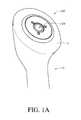
- FIG. 1Bis a cross-sectional view of FIG. 1A , showing the stemless humeral shoulder assembly disposed in the humeral head;
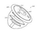
- FIG. 2is a perspective view of the stemless humeral shoulder assembly of FIGS. 1A and 1B ;
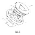
- FIG. 3is an exploded view of the stemless humeral shoulder assembly of FIG. 2 ;
- FIG. 4is a top view of the base member of the shoulder assembly of FIG. 2 ;
- FIG. 5is a first side view the base member of FIG. 4 ;
- FIG. 6is a second side view of the base member of FIG. 4 ;
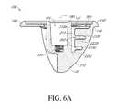
- FIG. 6Ais a cross-section of the base member shown in FIG. 6 through line 6 A- 6 A in FIG. 4 ;
- FIG. 7is a top perspective view of an anchor member of the shoulder assembly of FIG. 2 ;
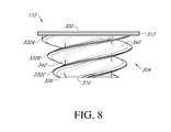
- FIG. 8is a side view of the anchor member of FIG. 7 ;
- FIG. 9is a bottom view of the anchor member of FIG. 7 ;
- FIGS. 10A-10Hillustrate steps of various methods of implantation of the stemless humeral shoulder assembly of FIG. 2 ;
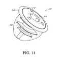
- FIG. 11is a top perspective view of another embodiment of a stemless humeral shoulder assembly
- FIG. 12is a top perspective view of a base member of the stemless humeral shoulder assembly of FIG. 11 ;
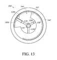
- FIG. 13is a top view of the base member of FIG. 12 ;
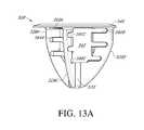
- FIG. 13Ais a side view of the base member of FIG. 12 ;
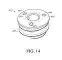
- FIG. 14is a top perspective view of an anchor member of the stemless humeral shoulder assembly of FIG. 11 ;
- FIG. 15is a top view of the anchor member of FIG. 14 ;
- FIGS. 16A-16Cillustrate steps of various methods of implantation of the stemless humeral shoulder assembly of FIG. 11 ;
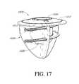
- FIG. 17is a top perspective view of another embodiment of a stemless humeral shoulder assembly
- FIG. 18is a top perspective view of a base member of the stemless humeral shoulder assembly of FIG. 17 ;
- FIG. 19is a top view of the base member of FIG. 18 ;
- FIG. 20is a side view of the base member of FIG. 18 ;
- FIG. 21is a bottom view of the base member of FIG. 18 ;
- FIG. 22is a cross-sectional view of the base member of FIG. 19 along line 22 - 22 ;
- FIG. 23is a top perspective view of an anchor member of the stemless humeral shoulder assembly of FIG. 17 ;
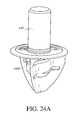
- FIGS. 24A-24Billustrate tool and component combinations that can be provided in various methods of implantation of the stemless humeral shoulder assembly of FIG. 17 ;
- FIG. 25illustrates an adaptor or centering pin that can be used to align a driver with a base member, as discussed herein;
- FIG. 26illustrates the performance of various embodiments of stemless humeral shoulder assemblies
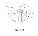
- FIG. 27is a cross-sectional view of another embodiment of a shoulder assembly having a locking device disposed between a base member and an anchor member thereof to reduce or eliminate disengagement of the anchor member from the base member;
- FIG. 27Ais an enlarged view of the locking device shown in FIG. 27 taken through line 27 A- 27 A;
- FIG. 28is a top perspective view of an anchor member assembly of the shoulder assembly of FIG. 27 ;
- FIG. 29is a side view of a shoulder assembly having another embodiment of a locking device
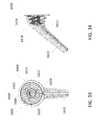
- FIG. 30is a side view of an anchor member of the shoulder assembly of FIG. 29 ;
- FIG. 31is a top view of a shoulder assembly having another embodiment of a locking device.
- FIG. 32is a bottom perspective view of a tool for actuating a locking structure of the locking device of the shoulder assembly of FIG. 31 from a disengaged configuration to an engaged configuration.
- FIGS. 33 and 34are a top perspective and side views of a humeral implant including the anchor member.
- FIG. 35is a side view of a stem of the humeral implant of FIG. 33 without anchor member.
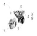
- FIG. 36is a view showing the components of a stemless humeral implant having one or more surfaces formed by additive manufacturing.
- FIG. 37is a top perspective view of another embodiment of a humeral implant with a stem, at least a portion of the implant being formed by additive manufacturing.
- FIG. 1Ashows a humeral shoulder assembly 100 that has been implanted in an exposed face F of a humerus H.
- the assembly 100has a recess 104 in which further components of a prosthetic shoulder joint can be secured.
- the configuration of the assembly including the recess 104enable the humerus H and a corresponding scapula to be fitted with either an anatomical shoulder or a reverse shoulder configuration either initially or as part of a revision procedure.
- FIG. 1Bshows that in certain applications, the shoulder assembly 100 can be fully retained within a head h of the humerus H. In other words, the distal-most portion of the assembly 100 is disposed in the humeral head h.
- the assembly 100does not have members that protrude beyond the head h into the intramedullary canal. This arrangement is less invasive and simplifies the procedure compared to a procedure involving a humeral component with a stem, as discussed elsewhere herein.
- FIGS. 2-9elaborate on advantageous structures and variations of the shoulder assembly 100 that can be employed in the stemless approach of FIGS. 1A-1B . Methods of using the shoulder assembly 100 are discussed below in connection with FIGS. 10A-10H . Shoulder assemblies capable of being at least partly delivered over a guide wire are discussed below in connection with FIGS. 11-16C .
- FIGS. 17-24Billustrate shoulder assemblies where a joint interface mounting platform or recess is disposed on a base member and an anchor member is provided primarily or solely for bone securement function.
- FIG. 25shows an adaptor that can be used in connection with several embodiments and methods of applying shoulder assemblies.
- FIG. 26illustrates the performance of certain embodiments compared to a prior art design. While incremental differences in these embodiments and methods are discussed below, it is to be understood that features of each embodiment can be combined with features of the other embodiments, as appropriate.
- FIGS. 2 and 3show more detail of components of the shoulder assembly 100 that among other features and advantages provides an anchor member with an inwardly positioned cylindrical member that reinforces outwardly positioned helical structures as discussed below.
- the assembly 100has a base member 108 and an anchor member 112 .
- FIG. 3shows that the base member 108 and anchor member 112 are separable components that can be applied to the patient separately, e.g., assembled in multiple steps within the bone as discussed below.
- the base member 108has a distal end 120 and a proximal end 124 .
- the distal end 120is configured to be embedded in the head of a humerus.
- the proximal end 124is configured to be disposed adjacent to a face of the humerus or another bone surface.
- the base member 108has a plurality of spaced apart arms 128 projecting from the proximal end 124 to the distal end 120 .
- the base member 108also has a central portion, e.g., a cylindrical member 130 , that forms part of the recess 104 , as discussed in more detail below.
- the arms 128are equally spaced about the cylindrical member 130 .
- the arms 128can be spaced apart by about 120 degrees.
- the base member 108 and the other base members discussed belowcan have three arms.
- the base member 108 and the other base members discussed belowcan have one or a plurality of arms 128 .
- the base member 108 and the other base members discussed belowcan have two, three, four, five, or six arms.
- the arms 128preferably are thin in the circumferential direction such that large gaps are provided between the arms.
- FIGS. 3 and 4show the proximal end 124 of the base member 108 in more detail.
- the proximal end 124can include a peripheral member 140 disposed about the outer periphery of the proximal end 124 .
- the peripheral member 140can be coupled with proximal ends 144 of the arms 128 (see FIGS. 5-6A ) to provide a unitary structure.
- the peripheral member 140comprises an annular structure 145 that is tapered such that a convex surface 146 is provided between proximal and distal portions of the peripheral member 140 .
- the convex surface 146extends from a bone engaging side of the peripheral member 140 to a proximal side of the peripheral member 140 .
- the proximal side of the peripheral member 140is disposed adjacent to but may be spaced from another joint component, such as a portion of an assembly including an anatomical or reverse shoulder joint humeral interface.
- the proximal end 124can include a plurality of guide members 148 that can be coupled with the peripheral member 140 .
- the guide members 148can include plate-like projections extending radially inwardly from an arcuate segment of the peripheral member 140 .
- the guide members 148can be coupled with, attached to or a monolithic extension of an inner edge of the peripheral member 140 .
- the base member 108includes three guide members 148 .
- the guide members 148can include an angled or lead surface 152 that is angled relative to a transverse plane of the proximal end 124 .
- a transverse plane of the proximal end 124is a plane that extends perpendicular to a longitudinal axis A (see FIGS. 5 and 6A ) of the cylindrical member 130 .
- the angle of the lead surface 152is selected to match the angle of a distal face of a helical structure of the anchor member 112 as discussed further below in connection with FIGS. 6A and 8 .
- each of the guide members 148includes a flat surface 156 .
- Each of the flat surfaces 156can be disposed on a transverse plane of the proximal end 124 .
- the flat surfaces 156can extend between an outer portion 160 coupled with the peripheral member 140 and an inner portion 168 disposed adjacent to the cylindrical member 130 .
- each inner portion 168 of three guide members 148is spaced from the cylindrical member 130 by a corresponding gap 172 .
- the gaps 172partly define an annular volume (projecting distally into the page in FIG. 4 ) in which a cylindrical portion of the anchor member can be disposed, as discussed further below.
- FIG. 3shows that the flat surface 156 can be disposed at an elevation distal of (or below) the proximal-most aspect of the peripheral member 140 .
- the distance between the proximal-most aspect of the peripheral member 140 and the flat surface 156can provide a space into which at least a portion of the anchor member 112 can be recessed.
- a proximal end 180 of the cylindrical member 130is disposed at about the same elevation of the proximal-most aspect of the peripheral member 140 .
- an outside surface of the cylindrical member 130 and an inside surface of the peripheral member 140define side surfaces of an annular space into which a proximal portion of the anchor member 112 can be received.
- annular space bounded by the outside surface of the cylindrical member 130 and the inside surface of the peripheral member 140provides a substantially flush, e.g., stepless, profile or transition from the inner and proximal-most aspect of the peripheral member 140 to an outer periphery 182 A of the anchor member 112 and from an inner periphery 182 B of the anchor member to the proximal end 180 of the cylindrical member 130 .
- the flush profileenables other components of a shoulder joint to be drawn down adjacent to but preferably spaced from the assembly 100 .
- FIG. 4shows that the guide members 148 generally are spaced apart by arcuate openings 192 .
- the openings 192extend from a lower end of one of the angled surfaces 152 to an end of an adjacent guide member 148 .
- the openings 192permit laterally extending portions of the anchor member 112 to be advanced into the base member 108 .
- the laterally extending projectionsinclude one or more, e.g., three, threads that can be advanced through the openings to engage with the base member 108 at a position distal of the guide members 148 .
- FIG. 4shows that the arms 128 are disposed distal of but accessible through the openings 192 .
- the arms 128are located at a circumferential position between the angled surface 152 of a first guide member 148 and a non-angled surface of a second guide member 148 , where the second guide member is adjacent to the first guide member.
- the circumferential position of the arms 128is closer to the circumferential position of the non-angled surface of the second guide member 148 as shown.
- the circumferential positionis determined by projecting these structures to the plane upon which the non-angled surface 148 is disposed.
- FIG. 6Ashows that a proximal portion of the arms 128 is located distal of the distal-most aspect of the angled surface 152 .
- FIG. 6Ashows one of the arms 128 in more detail.
- the arms 128are each identical.
- the armsdiffer from each other.
- the armsdiffer from each other in having slots advanced distally from a first arm to a next arm in the direction of rotation of an anchor member to accommodate the path of the helical member or thread, as discussed below in connection with those embodiments.
- the arms 128have a plurality of slots 202 , e.g., three slots disposed between proximal and distal ends thereof.
- proximal-most slot 202can be different from the two slots 202 disposed distal thereof in that the proximal-most slot 202 is bounded by a lower surface 218 A discussed below but not by a corresponding upper edge formed in the arm 128 .
- the arm 128is coupled with the peripheral member 140 at a proximal end 144 of the arm 128 .
- a unitary structureis provided. In such a structure, a continuous structure can be provided from within the peripheral member 140 to within a proximal portion of the arm 128 so that there are no welds or joining lines or boundaries in this area. Such an arrangement simplifies the structure and eliminates potential areas for concentration of stress and potentially failure.
- An outer edge 210 of the arms 128provides a continuously arcuate sloping surface in one embodiment.
- the sloping surfacecan facilitate insertion of the base member 108 into an exposed humeral face F as discussed above and further below in connection with FIGS. 10A-10H .
- An inner edge 214 of the arm 128can include one or a plurality of, e.g., three, laterally extending faces or surfaces 218 A, 218 B, 218 C.
- the angle of the surfaces 152 , 218 A, 218 B, 218 Ccan be configured to facilitate advancement of a lateral extent of the anchor member 112 along a helical path. For example, initial advancement of a lateral portion of the anchor member 112 can cause a leading edge surface of the anchor member 112 to slide along the surface 152 shown in FIG. 6A . Continued advancement can cause the leading edge surface of the anchor member 112 to approach and then slide across the surface 218 A shown in FIG. 6A . Continued advancement can cause the leading edge surface of the anchor member 112 to approach and then slide across a surface 218 B of an arm 128 disposed adjacent to and on a first side of the arm 128 shown in FIG. 6A .
- At least some of the surfaces 218 A, 218 B, 218 Ccan be disposed in laterally projecting recesses or channels of the arms 128 .
- the surface 218 Bextends laterally outwardly from the inner edge 214 of the arms 128 .
- a corresponding surface 222 Bcan extend outwardly from the inner edge 214 adjacent to the surface 218 B.
- the surfaces 218 B, 222 Bcan be substantially parallel along their length.
- the surfaces 218 B, 222 Bcan be spaced apart by a short distal-proximal distance. The short distal-proximal distance can be about the same as the thickness of lateral protrusions (e.g., threads) of the anchor member 112 discussed below.
- both of the surfaces 218 B, 222 Bplay a role in guiding the advancement of the anchor member 112 .
- the face 222 Bcan have an angled surface similar to that of the surface 218 B.
- the angle of the face 222 Bcan be the same angle as that of the face 218 B.
- each of the faces 218 A, 218 B, 218 Chas a length as measured radially away from the axis A that differs from the length of the other faces.
- the distal-most face 218 Ccan have the shortest length.
- the proximal-most face 218 Acan have the longest length.
- a face 218 B disposed between the distal- and proximal-most faces 218 C, 218 Acan have an intermediate length.
- These lengthscan correspond to the tapered profile of the base member 108 , e.g., with the arms 128 having a generally convex shape from proximal to distal as viewed from the side.
- the lengths of the faces 218 A, 218 B, 218 Ccan correspond to the profile of the lateral projection of the anchor member 112 , which is some embodiments may be tapered.
- the proximal-most face 218 Adoes not have a corresponding face on the arm 128 disposed proximal thereof.
- a lower surface of the guide member 148 disposed adjacent to but clockwise of the arm 128can abut a proximal side of a thread while a distal side of the thread advances along the face 218 A.
- each of the faces 218 A, 218 B, 218 Chas a corresponding surface that together guide a thread of the anchor member 112 as discussed further below.
- each armhas a plurality of, e.g., three faces 218 A, 218 B, 218 C.
- the face 218 A of each of the arms 128is disposed at the same elevation as the corresponding face 218 A of adjacent arms 128 .
- the face 218 B of each of the arms 128is disposed at the same elevation as the corresponding face 218 B of adjacent arms 128 .
- the face 218 C of each of the arms 128is disposed at the same elevation as the corresponding face 218 C of adjacent arms 128 .
- This constructiondefines a plurality of helical paths on the base 108 for guiding helical members, as appropriate for certain embodiments.
- a first helical pathis defined by a face 218 A of a first arm 128 , a face 218 B of a second arm 128 adjacent to but disposed clockwise of (as defined above) the first arm, and a face 218 C of a third arm 128 adjacent to but disposed counter-clockwise of (as defined above) the first arm.
- the first helical pathalso includes the lead surface 152 disposed above and circumferentially between the first and third arms 128 .
- a second helical pathcan extend from a surface 152 to the second arm 128 to a face 218 C of the first arm 128 .
- a third helical pathcan extend from a surface 152 of the third arm 128 to a face 218 C of the second arm 128 .
- Each of the surfaces on the helical pathscan have substantially the same angle relative to a transverse plane of the base 108 . In some embodiments, the angle of the faces 218 A, 218 B, 218 C can be different.
- three left-handed helical pathscan be provided, each one commencing with an oppositely oriented surface similar to the surfaces 152 and traversing counter-clockwise to a face 218 A below and on the arm 128 immediately counter-clockwise of the oppositely oriented surface, then to the face 218 B on the next arm 128 and then to the face 218 C on the next arm 128 .
- the “next arm 128 ”is the arm circumferentially spaced from and immediately counter-clockwise of the arm from which the path extends.
- FIG. 5shows that a gap 232 A is provided between the inner edge 214 and the cylindrical member 130 below the face 218 A.
- a gap 232 Bis provided between the inner edge 214 and the cylindrical member 130 below the face 218 B.
- a gap 232 Cis provided between the inner edge 214 and the cylindrical member 130 below the face 218 C.
- the gap 232 Cis substantially the same width as the gaps 232 A, 232 B.
- the gaps 232 A, 232 B, 232 Care substantially the same as the gap 172 .
- the gaps 172 , 232 A, 232 B, 232 Cdefine part of a cylindrical space configured to receive part of the anchor member 112 as discussed further below.
- the gap 232 Cenables a distal portion of the anchor member 112 to be advanced distal of the face 218 C.
- FIG. 6Ashows that in some embodiments, the cylindrical member 130 has a threaded recess 250 formed in a lower portion thereof.
- the threaded recess 250enables a component to be advanced into engagement with the base member 108 .
- the componentcan be another component of a prosthetic joint or can be a tool used in placement of one or more components of the shoulder assembly 100 .
- the recess 250can engage a guide tool 432 (see FIG. 25 ) in one technique, discussed in more detail in connection with FIG. 10F .
- FIGS. 2 and 7-9illustrate features of the anchor member 112 which, as discussed above, is advanceable into the base member 108 to a position disposed within the arms 128 .
- the anchor member 112includes a proximal face 300 , a helical structure 304 disposed distally of the proximal face 300 , and a cylindrical sleeve 308 configured to be disposed around the recess 104 .
- the sleeve 308is configured to be advanced over and receive the cylindrical member 130 as discussed further below.
- the proximal face 300comprises the proximal side of a disc structure 312 disposed at the proximal end of the anchor member 112 .
- the disc structure 312is configured to be disposed in a space partly bounded by the flat surfaces 156 , the inner face of the peripheral member 140 , and the outer face at the proximal end 180 of the cylinder member 130 of the base member 108 (see FIG. 3 ).
- the disc structure 312can have a thickness (proximal-to-distal distance) substantially the same as the distance from the flat surfaces 156 to the proximal most aspect of the peripheral member 140 .
- the anchor member 112is configured such that regions 320 ( FIG. 9 ) of the distal surface of the disc structure 312 are advanced into a position to abut the flat surfaces 156 of the base member 108 when the shoulder assembly 100 is assembled.
- FIGS. 8 and 9show the helical structure 304 in more detail.
- the helical structure 304includes three spaced apart helical protrusions 332 A, 332 B, 332 C.
- the anchor member 112has a triple lead configuration.
- Other embodimentscan have a single lead (as in the embodiments discussed in connection with FIGS. 11 and 17 below), a double lead, or a quadruple lead configuration.
- Distal ends of the three helical protrusions 332 A, 332 B, 332 Ccan be seen in FIG. 9 .
- Each of these helical protrusions 332 A, 332 B, 332 Chas progressively larger diameter from a distal end to a proximal end thereof in the illustrated embodiment.
- the larger size toward the proximal endenables the helical protrusions to project farther laterally into the faces 218 A, 218 B, 218 C of the arms 128 .
- the smaller size toward the distal endenables the disruption of bone toward the distal end to be minimized.
- the helical protrusionscan be threads in some embodiment.
- FIG. 8shows distal and proximal faces 336 , 340 of one of the helical protrusions.
- the distal face 336is configured to be advanced along one or guided by one of the helical paths described above.
- the distal face 336is angled relative to a transverse (e.g., perpendicular) cross-sectional plane of the anchor member 112 , which angle may be selected to match the lead surface 152 , as discussed above.
- the distal face 336can slide along the lead surface 152 , one of the faces 218 A, one of the faces 218 B, and one of the faces 218 C.
- the proximal face 340can slide along or be guided by the surface 228 B ( FIG. 6A ) or another distally-oriented face disposed in one of the arms 128 or on a lower surface of the guide member 148 .
- FIG. 8shows that a spiral or helical surface 342 extends between adjacent helical protrusions 332 A, 332 B, 332 C.
- the spiral surface 342can extend from the base of a distal surface 336 of the helical protrusion 332 B to the base of the proximal surface of the helical protrusion 332 C.
- the spiral surface 342has a proximal to distal dimension that is about the same as the proximal-distal dimension of the side surface 214 between the surfaces 218 A, 228 B (See FIG. 6A ).
- the proximal to distal dimension of the spiral surface 342is about 50% larger than and in some cases twice as large as the proximal to distal dimension of the helical protrusions 332 A, 332 B, 332 C.
- FIG. 2shows that the anchor member 112 projects into the arms 128 and into a space between the arms when the anchor member and the base member are assembled.
- the anchor member 112is exposed between the arms 128 when advanced into the base member 108 .
- a plurality of elongate segments 352 of the helical protrusions 332 A, 332 B, 332 Care not covered by the faces 218 A, 218 B, 218 C, 222 B of the arms 128 but rather are located in an open area between the arms.
- the exposed segments 352create areas of engagement with the bone that vastly increase the initial pull-out force of the assembly 100 when initially placed. This improved initial pullout force greatly reduces the chance of dislodgement, as discussed below in connection with FIG. 26 .
- Some additional unique features of the assembly 100include helical surfaces in the anchor member 112 that mate only in very small and spaced apart areas of the base member 108 while exposing a majority of the helical surface to allow the exposed areas to be disposed directly in the bone for direct contact therewith.
- a portion of the helical surfaceis disposed within the arms 128 and not exposed but a majority of the helical surface is exposed to be embedded in bone.
- the percentage of the surface area of the exposed segments 352 to the total area of the helical protrusions 332 A, 332 B, 332 Cis between about 80 and 98% in some embodiments.
- the percentage of the area of the exposed segments 352 to the total area of the helical protrusions 332 A, 332 B, 332 Cis between about 85 and 95% in some embodiments.
- the percentage of the area of the exposed segments 352 to the total area of the helical protrusions 332 A, 332 B, 332 Cis about 91% in some embodiments.
- the ratio of the length of the exposed segments 352 to the total length of the helical protrusions 332 A, 332 B, 332 Cis between about 0.8 and about 0.98, e.g., between about 0.85 and about 0.95, e.g., about 0.9 in various embodiments.
- the structure provided hereinenables the threads to extend a large distance from the center of the recess 104 .
- the lateral extent, e.g., radius of the helical protrusions 332 A, 332 B, 332 Ccan be at least 50% of the lateral extent, e.g., radius of the peripheral member 140 , for example, at least about 50% and/or less than or equal to about 75%.
- the lateral extent of at least one of the helical protrusions 332 A, 332 B, 332 Ccan be at least about 50%, such as between about 50% and about 55%, of the diameter of the peripheral member 140 .
- the lateral extent of at least one of the helical protrusions 332 A, 332 B, 333 Ccan be at least about 60%, such as between about 60% and about 65%, of the diameter of the peripheral member 140 . In some embodiments, the lateral extent of the helical protrusions 332 A, 332 B, 333 C can be at least about 70%, such as between about 70% and about 75%, of the diameter of the peripheral member 140 . In certain embodiments, as shown in FIG. 8 , the diameter of each of the helical protrusions 332 A, 332 B, 332 C can vary from the proximal face 300 to the distal end 310 of the anchor 112 .
- the diameter of a portion of the helical protrusions 332 A, 332 B, 332 C near the proximal face 300can be greater than the diameter of a portion of the helical protrusions 332 A, 332 B, 332 C near the distal end 310 .
- the percentagecan be measured against any portion of the protrusions 332 A, 332 B, 332 C.
- the lateral extent of the helical protrusion 332 Ccan be between about 50% and 55% of the diameter of the peripheral member 140
- the lateral extent of the helical protrusion 332 Acan be between about 70% and 75% of the diameter of the peripheral member 140 .
- FIG. 7shows that the proximal face 300 of the anchor member 112 can include a driver interface 364 to facilitate advancing the anchor member 112 into the base member 108 .
- the driver interface 364can take any suitable form, for example, as three spaced apart recesses.
- the recessescan be cylindrical recesses extending into the disc member 312 .
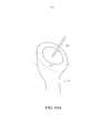
- FIGS. 10A-10Hillustrate methods of implanting the humeral shoulder assembly 100 into the humerus H.
- surgical accesshas been provided to the humerus H and the humerus has been prepared.
- Preparing the humerus Hcan include cutting off a joint-facing portion of the humeral head h.
- the joint facing portioncan be further prepared, for example by providing a countersunk region CS in the exposed face F.
- the countersunk region CSenhances a low profile application of the assembly 100 as discussed further below.
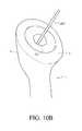
- a pin 400is placed in a central region of the countersunk region CS.
- FIG. 10Bshows that the pin 400 may be used to guide a reamer to create a well at the base of the pin.
- FIG. 10Cshows the well having received a tool 404 that has been advanced into the face F to modify the well to receive the base member 108 .
- the tool 404has a plurality of, e.g., three, radial projections 406 to create channels radiating from the well as shown in FIG. 10D .
- the projections 406have an edge profile similar to that of the arms 128 , e.g., with a convex edge from proximal to distal when viewed from the side similar to the edge 210 .
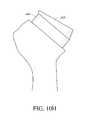
- FIG. 10Dshow the expose humeral face F with the pin 400 and tool 404 removed so that a created recess CR in the face F is shown.
- the recess CRis configured to permit the base 108 to be advanced with ease into the face F of the humeral head h as shown in FIG. 10E .
- the recess CRis shaped to match the shape of a portion of the base member 108 that projects distally.
- FIG. 4shows that the arms 128 can be equally spaced about the base member 108 , e.g., outer ends thereof coupled with the peripheral member 140 can be spaced circumferentially by about 120 degrees.
- the arms 128can be thin at radially outer portions thereof and can be joined adjacent to the distal end 120 of the base member 108 . Accordingly, the radial projections of the recess CR created by the radial projections 406 of the tool 404 can be narrow and spaced apart by the same amount as the arms 128 , e.g., about 120 degrees apart.
- the projection 406 and corresponding projections of the recess CRare generally straight, radial projections, the projections 406 could be curved and/or can extend away from a central region to in a non-radial direction matching the shape and orientation of any projections of the base member 108 .
- the insertion of the base member 108 into the recess CRcan be achieved with ease, e.g., without an impactor or any other tools, but rather by hand force.
- the base member 108advantageously is symmetrical about the axis A (see FIGS. 4 and 5 ). This allows the surgeon to insert the base member 108 in any orientation provided that the arms 128 and the projections in the recess CR are aligned. Other configurations have a preferred orientation, as discussed further below.
- FIGS. 10E-10Fshow that the countersunk region CS is configured to receive the peripheral member 140 in a recessed position.
- the countersunk region CShas a bone recessed area, which is recessed by about the proximal-distal dimension 416 (shown in FIG. 6 ) of the peripheral member 140 .
- the base member and/or the humeral shoulder assembly 100can positioned as desired relative to the face F of the humeral head h, e.g., with a small gap or flush mounted.
- Flush-mountenables a joint interface coupled with the assembly 100 to be positioned close to the face F, e.g., with little to no gap therein. Consistent and accurate positioning of the assembly 100 and joint interface can be important factors in properly locating the prosthetic joint interface.
- FIG. 10Fshows that after the base member 108 has been inserted into the face F of the humerus a subsequent step can involve coupling the guide tool 432 with the base member.
- FIG. 25shows details of one embodiment of the guide tool 432 .
- the guide tool 432preferably includes a guide body 436 disposed at a proximal portion thereof.
- the guide body 436projects outside and proximally of the base member 108 and is configured to guide the anchor member 112 to be advanced thereover.
- the guide body 436is a cylindrical member.
- a distal portion 440 of the guide tool 432is configured to be coupled with the base member 108 .
- a threaded distal portion 444is configured to mate with the threads in the threaded recess 250 (see FIG. 6A ).
- a tapered portion 448facilitates insertion of the guide tool 432 into the cylindrical member 130 of the base member 108 . More particularly as shown in FIG. 6A , the cylindrical member 130 can be tapered on an inside surface thereof, such that the recess formed in the member 130 is narrower at the distal end than at the proximal end thereof. Stated another way, a wall surrounding the recess in the cylindrical member 130 is closer to the axis A near the threads 250 than near the proximal end of the recess.
- the outside surface of the tapered portion 448is closer to a central longitudinal axis B of the guide tool 432 than is a proximal portion of the tapered portion 448 .
- the tapersmatch such that if the guide tool 432 is inserted into the cylindrical member 130 with the axis A, B offset, the surface 448 and the inside surface of the recess in the cylindrical member 130 match to align these axes before the threads 444 and the threads in the recess 250 .
- FIG. 10Gshows the anchor member 112 engaged with the base member 108 .
- This configurationresults from advancement of the anchor member 112 over the guide tool 432 in one method.
- a method stepincludes coupling a driver with the driver interface 364 on the proximal face 300 of the anchor member 112 .
- the drivercan take any suitable form, e.g., can include a plurality of protrusions configured to mate with recesses of the driver interface 364 .
- the drivercan be configured to snap into or onto the anchor member 112 at the driver interface 364 . Embodiments of a driver are discussed below in connection with FIGS. 16B and 24B .
- the driverhas a ratchet mechanism such that the surgeon can continuously hold the tool and need not release the handle to re-grip it to apply additional turns to the anchor member 112 .
- one advantage of the three thread design of the anchor member 112is that less rotation of the anchor member is required as compared to a two thread design or a one thread design to fully seat the anchor member in the base member 108 .
- the surgeonobserves the face F of the humerus and advances the anchor member 112 until some fluid is observed to emerge from the recess CR and/or around the assembly 100 .
- the emergence of fluidsuggests that the anchor member 112 is fully seated in the bone in a way providing excellent initial bone retention. Such retention provides enhanced pull-out force.
- FIG. 26illustrates the initial pull-out force 1510 for Embodiment A, a variant of the shoulder assembly 100 in which the anchor member 112 has a single continuous thread. Portions of the helical structure 304 project into the open area defined between the arms 128 and engage the bone thereby increasing the initial pull-out force of the assembly 100 when initially placed. As shown in FIG. 26 , the peak force corresponding to the initial pull out force 1510 of Embodiment A is at least ten times greater than the peak force corresponding to the initial pull out force 1500 of the prior art design having a base member and no anchor thread.
- the assembly 100enables a variety of joint interface components.
- the surgeoncan couple an anatomical joint interface with the assembly 100 , e.g., by positioning an anchor portion of the anatomical joint interface in the recess 104 .
- a reverse shoulder configurationis better for the patient.
- the surgeoncan dispose an anchor portion of a reverse configuration shoulder joint interface in the recess 104 .
- FIG. 10Hshows an adaptor 464 coupled with the recess 104 .
- the adaptor 464can be seated with a concave socket portion 468 that can be coupled with a convex head implanted in the scapula in the reverse shoulder configuration.
- the methods described above, e.g., in connection with FIGS. 10A-10H ,can include additional steps and employ additional tools as discussed below.
- the shoulder assembly 100also can be adapted to be compatible with other methods herein, e.g., having a guidewire passage suitable for employing over-the-wire methods discussed below.
- FIG. 11-16Cshow a stemless shoulder assembly 500 and methods similar to the shoulder assembly 100 and methods discussed above except as described differently below.
- the assembly 500is configured to allow a guidewire to be used to advance components thereof into a prepared humeral face F, providing for an efficient and accurate procedure.
- the assembly 500includes a recess 504 , a base member 508 , and an anchor member 512 .
- a thread or other helical protrusion 532extends from the anchor member 512 into engagement with the base member 508 and into an open area where it can engage bone.
- the anchor member 512has a single lead configuration.
- Other embodimentscan have a multiple lead configuration, e.g., including a double lead, a triple lead, or a quadruple lead configuration.
- FIGS. 12, 13 and 13Ashow features of the base member 508 that facilitate delivery of the base member and/or the anchor member 512 over a guidewire.
- the base member 508has a plurality of arms 528 A, 528 B, 528 C that extend between a distal and a proximal end 520 , 524 of the base member 508 .
- the arms 528 A, B, Care coupled with a sleeve 530 disposed adjacent to the distal end 520 of the base member 508 .
- the sleeve 530has an opening at a proximal end 534 thereof extending into a lumen 538 .
- the lumen 538extends from the opening at the proximal end 534 to an opening at the distal end 520 of the sleeve 530 .
- the lumen 538is accessible through an open space 542 disposed between the arms 528 A, B, C and between the proximal end 534 of the sleeve 530 and the proximal end 524 of the base member 508 .
- the space 542provides access to the lumen 538 by a direct path, e.g., a path perpendicular to the plane of the proximal end 524 of the base member 508 .
- FIG. 12shows that the base member 508 includes a guide surface 548 and a lead surface 552 in some embodiments.
- the guide and lead surfaces 548 , 552can be regions of a continuous guide member and can be a continuous expanse without a change in orientation between them.
- the guide surface 548can be substantially flat, e.g., disposed on a plane that is perpendicular to a longitudinal axis C of the lumen 538 .
- the lead surface 552can be angled to match the pitch of the helical protrusion 532 (see FIG. 14 ) on the anchor member 512 .
- the guide member or the guide and lead surfaces 548 , 552can be disposed adjacent to a periphery of the base member 508 , e.g., between a peripheral member 540 and the axis C.
- the guide and lead surfaces 548 , 552are coupled at outer edges thereof with an inner edge of the peripheral member 540 .
- a circumferential gap 544is provided between ends of the guide and lead surfaces 548 , 552 .
- the gap 544is configured to permit the helical protrusion 532 (see FIG. 14 ) to be advanced along the lead surface 548 to a top laterally extending surface 560 A of the first arm 528 A, which is disposed beneath the gap 544 .
- FIG. 13Ashow the path from the lead surface 552 to the top surface 560 A through the gap 544 is a first segment of a helical path about the axis C.
- a second segment of the helical pathextends from the top laterally extending surface 560 A to a top laterally extending surface 560 B on the arm 528 B.
- a third segment of the pathextends from the top laterally extending surface 560 B to a top laterally extending surface 560 C of the arm 528 C.
- a fourth segment of the pathextends from the top laterally extending surface 560 C to a laterally extending surface 564 A of the arm 528 A below the surface 560 A.
- the laterally extending surface 564 Ais a mid-level surface on the arm 528 A.
- the helical path through the base 508extends in the same manner across a plurality of mid-level surface corresponding to the surface 564 A and a plurality of surfaces at a lower level of the arms to a distal end point on or adjacent to or at a laterally extending surface 568 C.
- the helical path described aboveaccommodates a single helical protrusion, e.g., thread, of the anchor member 512 .
- An advantage of this designis that only a single thread must traverse a gap in the proximal surface of the base portion 508 .
- the threadis much longer than the thread of the anchor member 112 and is generally at a shallower angle and so may be advanceable along the helical path with less torque than is required for the anchor member 112 .
- FIGS. 14 and 15show further details of the anchor member 512 .
- the anchor member 512has a proximal face 600 having a tapered annular surface.
- the proximal face 600can include a driver interface 604 that can take any suitable form, such as any of those described above.
- driver interface 604can include a plurality of recesses.
- FIG. 15shows that the recess 504 can extend from the proximal face 600 to a distal end having an aperture 608 formed therein.
- the aperture 608can be configured to receive a guidewire such that the anchor member 512 can be advanced over a wire, as discussed further below.
- FIGS. 16A-Cillustrate various methods of implanting the shoulder assembly 500 .
- the methodcan include compatible steps of any of the methods discussed above in connection with FIGS. 10A-10H , including initial preparation of a humeral head with a recess to receive a guidewire 650 .
- the guidewire 650can take any suitable form and is sometimes known as a Kirschner wire or K-wire.
- the guidewire 650is placed into a recess extending distally into a face of a humeral head.
- the base member 508is advanced over the proximal end 654 of the guidewire 650 , e.g., an opening at the distal end of the lumen 538 is advanced over the proximal end 654 of the guidewire 650 .
- the lumen 538is sized so that the base member 508 can easily slide along the length of the guidewire 650 to a position corresponding to the position of the base member 108 in FIG. 10E .
- the base member 508is advanced into the bone.
- the base membercan be urged into the recess with low force, e.g., with hand force and without impactors or with light force from the impactor.
- the gap 544is oriented with respect to the anatomy.
- the gap 544can be disposed at a lower elevation (caudad) compared to the position of the guide surface 548 .
- FIG. 16Billustrates further step in which a cannulated driver 662 is advanced over the guidewire 650 .
- the cannulated driver 662preferably has an interface configured to mate with the driver interface 604 on the anchor member 512 .
- the driver 662can have a plurality of prongs extending distally therefrom to engage recesses in the face 600 of the anchor member 512 .
- the surgeoncouples the driver 662 with the anchor member 512 . Once so coupled, the driver 662 and the anchor member 512 are advanced over the guidewire 650 .
- An initial step of advancing the driver 662 and the anchor member 512 over the guidewire 650includes inserting the proximal end 654 of the guidewire 650 into the aperture 608 in the anchor member 512 . Continued advancement of the driver 662 and the anchor member 512 causes the guidewire 650 to be advanced through the driver 662 and out of a proximal end 668 thereof.
- the distal portion of the helical protrusion 532is placed against the guide surface 548 and/or the lead surface 552 and through the gap 544 and from there along the helical path discussed above.
- the cannulated driver 662can be removed leaving the shoulder assembly 500 in place as shown in FIG. 16C . Thereafter the guidewire 650 is removed to allow subsequent steps to proceed, including attachment of a joint interface as discussed above.
- the shoulder assembly 500is providing a single sleeve-like structure in the anchor member 512 rather than co-axial sleeve one in each of the base and anchor members.
- the anchor member 512includes a cylindrical structure.
- the cylindrical structure of the assembly 500reinforces the helical protrusion 532 and also comprises the recess 504 . This provides a simpler construction having fewer components. Also, there is no chance for multiple cylinders to be slid over each other to become misaligned, leading to binding or increased torque requirements for advancing the anchor member 512 into the base member 508 .
- FIGS. 17-24Billustrate an embodiment of a humeral shoulder assembly 1000 in which distally projecting arms are more rigid by virtue of being coupled to each other and directly to a cylinder member at intermediate positions. This structure retains the direct bone engagement of exposed threads while making the arms more rigid.
- FIG. 17illustrates the assembly 1000 having a base member 1008 and an anchor member 1012 .
- the base member 1008 and the anchor member 1012are separable components that can be applied to the patient separately, e.g., assembled in multiple steps within the bone in techniques similar to those discussed above.
- FIGS. 18-22illustrate various views of the base member 1008 .
- the base member 1008has a distal end 1020 configured to be embedded in bone and a proximal portion 1024 to be disposed adjacent to the face F of the humerus H or another bone surface.
- the base member 1008can have a plurality of spaced apart arms 1028 projecting from the proximal portion 1024 to the distal end 1020 of the base member 1008 .
- Each arm 1028can define an outer edge 1210 having an arcuate sloping surface. The sloping surface can facilitate insertion of the base member 1008 into an exposed humeral face F as discussed above in connection with FIGS. 10A-10H .
- each armcan define an inner edge 1214 .
- the inner edge 1214 of a distal portion 1046 of each of the armscan be connected to form the distal end 1020 of the base member 1008 (see FIG. 21 ).
- each arm 1208can include one or more laterally extending recesses 1218 A, 1218 B, 1218 C.
- the number of laterally extending recessescan vary between different arms 1028 .
- a first armcan include a first recess 1218 A and a second recess 1218 B, while a second arm can include only one recess 1218 C.
- the recesses 1218 A, 1218 B of the first armcan be longitudinally displaced from the recess 1218 C of the second arm to accommodate a helical structure 1304 of the anchor member 1012 (see FIG. 17 ).
- each of the laterally extending recesses 1218 A, 1218 B, 1218 Ccan be equidistant from the longitudinal axis of the base member 1008 to accommodate an anchor member 1012 having a substantially constant outer diameter along the helical structure 1304 (see FIG. 17 ).
- the base member 1008can also include a central portion (e.g., a cylindrical member 1030 ). As shown in FIG. 22 , the cylindrical member 1030 can include an open proximal end 1034 and a closed distal end 1032 . The proximal end 1034 can define the proximal-most point of the base member 1008 . In certain aspects, the proximal end 1034 can include an annular groove 1076 ( FIG. 18 ) for receiving a c-ring that may be present to prevent loosening between the anchor member 1012 and the base member 1008 . A c-ring can be part of a locking device, as discussed further in connection with FIGS. 27-27A below.
- a threaded recess 1250can be formed in the distal portion of the cylindrical member 1030 .
- the threaded recess 1250enables a component to be advanced into a secure position of engagement with the base 1008 .
- the componentcan be part of a prosthetic joint interface or can be a tool used in placement of the shoulder assembly 1000 .
- the recess 1250can engage a guide tool 432 ( FIG. 25 ).
- the guide tool 432can extend the length of the cylindrical member 1030 to facilitate insertion of the anchor member 1012 into the base member 1008 .
- FIG. 20shows that the outer wall of the cylindrical member 1030 can define a helical channel 1050 (e.g., groove or opening).
- the outer wall of the cylindrical member 1030can connect to the inner edge 1214 of the arms 1028 , such that portions of the helical channel 1050 can align with each of the laterally extending recesses 1218 A, 1218 B, 1218 C to form a pathway for the helical structure 1304 of the anchor member 1112 (see FIG. 17 ).
- FIG. 19illustrates that the proximal portion 1024 of the base member 1008 can include a peripheral member 1040 disposed about the outer periphery of the proximal portion 1024 .
- the peripheral member 1040can be coupled with the proximal ends of the arms 1028 (see FIG. 22 ) to provide a unitary structure.
- the proximal portion 1024can include a guide member 1048 that can be connected to the peripheral member 1040 .
- the guide member 1048can be partially recessed from the proximal face of the peripheral member 1040 to provide a space into which a proximal disc structure 1312 of the anchor member 1012 can be positioned (see FIG. 17 ).
- the guide member 1048can include a plate-like projection extending radially inwardly from the peripheral member 1040 to a proximal portion of the cylindrical member 1030 .
- the guide member 1048can extend continuously from the inner edge of the peripheral member 1040 to the cylindrical member 1030 around at least about 50% of an inner diameter of the peripheral member 1040 .
- the guide member 1048can extend discontinuously from the inner edge of the peripheral member 1040 to the cylindrical member 1030 .
- a gap 1072can be defined adjacent to but radially inward of an arcuate segment of the guide member 1048 that is disposed between the peripheral portion 1040 and the gap 1072 . The gap 1072 facilitates insertion of the anchor member 1012 into the base member 1008 .
- the proximal end 1034 of the cylindrical member 1030can be elevated above the proximal-most aspect of the peripheral member 1040 .
- the proximal disc structure 1312can fill the annular space bounded by the outside surface of the cylindrical member 1030 and the inside surface of the peripheral member 1040 to create a tapered, annular surface from proximal end 1034 of the cylindrical member 1030 to the peripheral member 1040 .
- This structureavoids inflection points in the side profile of the assembly 1000 , which is advantageous in reducing or eliminating gaps between the assembly 1000 and another component of a shoulder joint assembly coupled therewith.
- FIG. 23illustrates features of the anchor member 1012 , which has a proximal disc structure 1312 .
- the proximal disc structure 1312can define a central opening 1316 that can surround the proximal end 1034 of the cylindrical member 1030 when the shoulder assembly 1000 is assembled.
- the proximal disc structure 1312can include a driver interface 1364 (e.g. a plurality of openings) for engaging a driving tool 450 (see FIG. 24B ). Rotating the driving tool 450 can advance the anchor member 1012 to rotationally engage the base member 1008 .
- the anchor member 1012can also include a continuous helical structure 1304 disposed distally of the proximal disc structure 1312 .
- the anchor member 1012has a single helical structure 1304 .
- Other embodimentscan have a multiple helices, e.g., including a double helix, a triple helix, or a quadruple helix configuration.
- the inner edge of the helical structure 1304can define the innermost edge of the anchor member 1012 distal of the disc structure 1312 in that the anchor member 1012 does not include a central body structure. In at least this sense, the anchor member 1012 has an open helix construction.
- the helical structure 1304defines a substantially constant inner diameter and a substantially constant outer diameter in one embodiment.
- the disc structure 1312When the shoulder assembly 1000 is assembled, the disc structure 1312 can abut the guide member 1048 of the base member 1008 and the helical structure 1304 can be disposed in the helical groove 1350 and the laterally extending recesses 1218 A, 1218 B, 1218 C of the base member 1008 (see FIG. 17 ). Portions of the helical structure 1304 project into the open area defined between the arms 1208 and engage the bone, thereby increasing the initial pull-out force of the assembly 1000 when initially placed. As shown in FIG. 26 , the peak force corresponding to the initial pull out force 1520 of the shoulder assembly 1000 is at least five times greater than the peak force corresponding to the initial pull out force 1500 of the prior art.
- FIGS. 24A-24Billustrate tools that can be used to implant the shoulder assembly 1000 and corresponding methods.
- the method of using the toolscan include compatible steps of any of the methods discussed above in connection with FIGS. 10A-10H including creating a recess CR in the humeral head (see FIG. 10D ).
- the base member 1008can be inserted into the face F of the humerus head h (similar to FIG. 10E ).
- the insertion of the base member 1008can be achieved without an impactor or any other tools, but rather just inserted by hand force.
- a subsequent stepcan involve coupling the guide tool 432 with the base member 1008 (see FIG. 24A ).
- FIG. 25illustrates one embodiment of the guide tool 432 .
- the guide tool 432can extend the length of the cylindrical member 1030 to guide the anchor member 1112 into the base member 1008 .
- the methodcan include coupling a driver 450 with the driver interface 1364 (see FIG. 24B ).
- the driver 450can take any suitable form, e.g., can include a plurality of protrusions configured to mate with openings of the driver interface 1364 .
- the driver 450has a ratchet mechanism such that the surgeon can continuously hold the tool and need not release the handle to re-grip it.
- the methods described above, e.g., in connection with FIGS. 24A-24Bcan include additional steps and employ additional tools as discussed above.
- the shoulder assembly 1000 and/or the tool 450also can be adapted to be compatible with other methods, e.g., with over-the-wire methods.
- the base member 1008can have a lumen extending through the distal end 1020 to guide the base member into place.
- a channel in the tool 450can be used in guiding the anchor member 1012 into place in the base member 1008 .
- FIGS. 27-32show features that can reduce or eliminate disengagement between a base member and an anchor member. These embodiments are illustrated in connection with the shoulder assembly 100 , but can be used in connection with any of the embodiments herein. Also, although the features are discussed separately they could be combined in some embodiments.
- FIGS. 27 and 27Ashows a shoulder assembly 1100 that includes a base member 1108 , an anchor member 1112 , and a locking device 1118 disposed adjacent to a proximal end 1124 of the base member 1108 .
- the locking device 1118comprises a C-ring 1122 that is disposed partially in a recess or groove 1126 (See FIG. 27A ) of the anchor member 1112 and partially in a groove 1130 (see FIG. 27A ) of the base member 1108 .
- FIG. 28shows a partial assembly in which the C-ring 1122 is coupled with the anchor member 1112 prior to coupling the anchor member 1112 to the base member 1108 .
- the C-ring 1122is disposed in the anchor member 1112 prior to implantation.
- FIG. 27Ashows that the cross-sectional shape of the C-ring 1122 facilitates actuation of the C-ring 1122 during assembly.
- a distal face 1134 of the C-ring 1122is angled relative to a plane oriented perpendicular to the distal-proximal direction of the assembly 1100 .
- the anchor member 1112is advanced into the base member 1108 until the distal face 1134 engages a proximal portion 1138 (See FIG. 27A ) of the base member 1108 and is deflected thereby into or deeper into the recess 1126 of the anchor member 1112 . This permits the anchor member 1112 to move relative to the base member 1108 until the C-ring 1122 moves to the position of the groove 1130 .
- FIG. 27Ashows the final position of the C-ring 1122 with a portion disposed in the groove 1130 and a portion disposed in the groove 1126 .
- the anchor member 1112is locked into the base member 1108 because further advancement of the anchor member 1112 into the base member 1108 is prevented by contact between a base face 1148 and an anchor face 1120 and because retraction of the anchor member 1112 from the base member 1108 is prevented by the C-ring 1122 in cooperation with grooves 1126 and 1130 (see FIG. 27 ).
- the C-ring 1122can be coupled with the base member 1108 prior to assembly of the anchor member 1112 with the base member 1108 .
- a surface of the anchor member 1112can be configured to deflect the C-ring 1122 into or deeper into the groove 1130 .
- a proximal face of the C-ring 1122may be angled relative to a plane oriented perpendicular to the distal-proximal direction of the assembly to facilitate deflection of the C-ring.
- a C-ringis illustrated, other structures that can be temporarily deflected into the recess 1126 or the recess 1130 can be used, such as spring loaded or resilient detents or members or other similar structures.
- FIGS. 29 and 30illustrate another embodiment of a shoulder assembly 1200 that has a base member 1208 , an anchor member 1212 , and a locking device 1218 comprising an interface between the anchor member 1212 and the base member 1208 .
- the locking device 1218includes a distal projection 1220 disposed on a distal side of a helical protrusion 1232 (see FIG. 30 ).
- FIG. 30shows that the distal projection 1220 can have a first face 1222 that is oriented generally proximal to distal and a second face 1226 that is disposed at an angle relative to a plane extending perpendicular to the proximal-distal direction of the anchor member 1212 .
- the anchor member 1212is advanced into the base member 1208 in the same manner as described above in connection with the assembly 100 .
- the second face 1226 of the projection 1220approaches a first side 1228 A of the arm 1228 of the base member 1208 .
- the second face 1226passes across a lower lateral face of an upper-most slot of the arm 1228 .
- local deformation of at least one of the arm 1228 and the projection 1220permits further advancement of the second surface 1226 relative to the arm until the first surface is disposed on the second side 1228 B of the arm 1228 (see FIG. 29 ).
- the local deformationis preferably temporary such that the deformed structure(s) return toward their undeformed state(s).
- the first face 1222abuts a corresponding surface of the second side 1228 B of the arm 1228 .
- the anchor member 1212is locked into the base member 1208 because further advancement of the anchor member 1212 into the base member 1208 is prevented by contact between an upper surface of the base member 1208 and an anchor face 1224 and because retraction of the anchor member 1212 from the base member 1208 is prevented by contact between the first face 1222 and the second side 1228 B of the arm 1228 .
- the locking device 1218is simple in construction in that a first portion of the interface is disposed on the anchor member 1212 and a second portion of the interface is disposed on the base member 1208 and thus does not require another separable component compared to the shoulder assembly 1100 . Also, the locking device 1218 does not require an additional discrete step in the locking of the base member 1208 to the anchor member 1212 because the final step of passing the projection 1220 from the first side 1228 A to the second side 1222 B is accomplished with the same rotation as is required in connection with the assembly 100 , though some additional force may be required to provide the local deformation discussed above.
- FIGS. 31 and 32show another embodiment of a shoulder assembly 1300 that has a base member 1308 , an anchor member 1312 , and a locking device 1318 comprising at least one, e.g., a plurality of deflectable prongs 1320 that can be deployed to span from one of the anchor member 1312 and the base member 1308 to the other of the anchor and base members.
- the spanning of the prong(s) 1320causes a portion of the prong to be engaged with the base member 1308 and another portion to be engaged with the rotatable anchor member 1312 such that rotation of the anchor member in either direction is reduced or eliminated.
- FIG. 31shows that the prongs 1320 can be disposed on the anchor member 1312 about an inner periphery 1332 of a disc structure 1336 thereof.
- the base member 1308can have a cylindrical member 1324 , similar to that discussed above in connection with the assembly 100 .
- the cylindrical member 1324can have a plurality of scallops or recesses 1328 disposed on a side surface thereof.
- the recesses 1328can extend entirely around the cylindrical member 1324 in one embodiment to enable the prong(s) 1320 to be engaged at a nearest recess 1328 rather than come precisely to rest at a specific rotational position and recess.
- the base and anchor members 1308 , 1312could be provided with the same number or prongs and recesses, wherein the location of the prongs and recesses are provided at an expected fully engaged position of the anchor member 1312 relative to the base member 1308 .
- FIG. 31shows the prong(s) 1320 in a disengaged position. Any suitable technique or tool can be used to deploy the prongs 1320 across a gap between the anchor member 1312 and the base member 1308 .
- FIG. 32illustrates a tool 1400 that can be used to deploy the prongs 1320 .
- the tool 1400includes a proximal user grip portion 1404 , which can be a cylindrical member or any other ergonomic gripping structure.
- the tool 1400also includes a plurality of pins 1408 disposed on a distal portion thereof that are configured and positioned to engage driver interfaces 1364 disposed on the proximal face of the disc structure 1336 .
- the pins 1408can be on an opposite side of the tool 1400 from the grip portion 1404 .
- the tool 1400also includes a plurality of prong actuators 1412 disposed on the same side of the tool as are the pins 1408 .
- the prong actuators 1412can each include a first, radially inward side 1416 and a second, radially outward side 1420 .
- An angled surface 1424is disposed between the sides 1416 , 1420 .
- the angled surface 1424is configured to engage the prongs 1320 and deflect and in some cases deform them as the tool 1400 is advanced.
- the radially outward side 1420is configured and positioned to be inserted into a recess 1340 disposed in the proximal faces of the disc 1336 radially outward of the prongs 1320 .
- This initial insertion of the prong actuator 1412 into the recess 1340can be up to a point where the angled surface 1424 first engages the prong 1320 .
- the radial distance from the first, radially inward side 1416 to the second, radially outward side 1420is greater than the radial extent of the recess 1340 .
- the radial distance from the first, radially inward side 1416 to the second, radially outward side 1420spans the recess 1340 , the gap between the anchor and base members 1312 , 1308 and into the scallop or recess 1328 . Further advancement of the tool 1400 causes the angled surface 1424 to engage the prong 1320 .
- the prong 1320to be deflected, e.g., bent or otherwise deformed into the recess 1328 of the base member 1308 .
- the prong 1320spans from the disc structure 1336 of the anchor member 1312 to the recess 1328 of the base member 1308 .
- the coupling of the prong 1320 with the base member 1308causes the anchor member 1312 also to be fixed relative to the bone. This prevents any backing out or unintended disengagement of the anchor member 1312 from the base member 1308 .
- one embodiment of the locking device 1318comprises six prongs 1320 .
- one prong 1320can be provided.
- a plurality of prongse.g., two three, four, five, twenty, or more prongs 1320 can be provided.
- the prongs 1320could be disposed on the base member 1308 and could be deflected, e.g., bent or otherwise deformed, into a scallop or recess disposed on the anchor member 1312 in other embodiments.
- the prong 1320can be configured as a spanning member that need not be formed as a part of either the base member 1308 or the anchor member 1312 but rather as a separate components installed at the proximal side of the assembly 1300 .
- the various locking devices discussed hereincan be combined to provide multiple locking structures.
- FIGS. 33-35illustrate a humeral implant 1600 and components thereof.
- the humeral implant 1600includes a stem and that combines the securement benefits of a stem with the securement benefits of the base and anchor member as discussed herein.
- FIGS. 33 and 34show the humeral implant 1600 includes a stem 1610 .
- the implant 1600also includes an anchor member 1612 .
- the anchor member 1612is similar to other anchor members discussed above. The description of the features of the other anchor members discussed herein may be combined with or substituted for the features of the anchor member 1612 described below.
- the anchor member 1612has a proximal face 1614 and a distal threaded portion 1618 .
- the distal threaded portion 1618can have a radially inner edge coupled with a cylindrical portion 1619 of the anchor member 1612 .
- a radial outer edge and an expanse between the inner and outer edges of the threaded portion 1618are adapted to be advanced into and then to be embedded in bone.
- the implant 1600provides high confidence in securement by combining the engagement between the threaded portion 1618 and the bone matter in the metaphysis with engagement between the distal portion 1636 of the stem 1610 and the bone matter surrounding the canal of the humerus.
- the stem 1610provides additional securement. See FIG. 26 and corresponding discussion for details of securement using such a threaded portion.
- the proximal face 1614can have a tool interface 1620 that can be engaged by a driver to advance the anchor member 1612 into or remove the anchor member from the stem 1610 .
- FIG. 34shows that the proximal face 1614 can be flush with a proximal portion of the stem 1610 when fully advanced. That is, the face 1614 can be positioned so that it does not protrude proximally of a proximal most aspect of the stem 1610 , which is discussed further below.
- proximal face 1614can be annular, providing an inner edge 1622 that allows access to a portion of the stem 1610 as discussed below.
- the inner edge 1622can be disposed at the proximal end of the cylindrical portion 1619 .
- the cylindrical portion 1619projects from the inner edge 1622 .
- FIG. 33also shows that the proximal face 1614 includes an outer edge 1624 that can be received by and in some cases surrounded by an outer periphery of a proximal portion of the stem 1610 .
- the stem 1610is advantageous in providing multiple modes of securement to a bone, e.g., to a proximal humerus. Compared to the aforementioned stemless designs, the stem 1610 gives a surgeon an option in evaluating a patient to be able to quickly adapt a surgical plan to an implant providing more security or providing security to a different bone segment, such as a canal which may be more robust than the cancellous bone disposed at or just beneath the resection plane.
- FIG. 35shows that the stem 1610 includes a proximal portion 1632 and a distal portion 1636 .
- the distal portion 1636is configured to be inserted through cancellous bone, for example through a resected humerus of a patient.
- a distal tip 1640 of the distal portion 1636can be inserted to extend into an intramedullary canal of the humerus.
- the distal portion 1636includes a central portion 1644 extending proximally from the distal tip 1640 , with one or more projections 1648 extending away from the central portion 1624 .
- the projections 1648can include two, three, four or more projections 1648 .
- the projections 1648are evenly spaced around the central portion 1644 . For example, if there are three projections 1648 , they may be spaced apart by 120 degrees.
- the projections 1648enable the distal portion 1636 to be inserted into the canal of a long bone, such as a humerus, along thin outer edges of the projections 1348 such that contact with the bone in the canal is initially line contact. This makes insertion of the distal portion 1636 easier because there is less friction between the stem 1610 and the bone. While this provides for relatively minimal surface contact, the anchor member 1612 provides excellent securement, as discussed further below.
- the proximal portion 1632includes a distal region that can have the same or a similar form to that of a proximal region of the distal portion 1636 .
- the distal region of the proximal portion 1632can have a central portion 1652 and one or a plurality of projections 1656 .
- the proximal portion 1632also can have one or more, e.g., three, projections.
- the stem 1610is configured such that when implanted in a long bone, e.g. in the humerus, the proximal portion 1632 is disposed in the metaphysis of the bone. That is, the bone may be resected and thereafter, the distal portion 1636 can be advanced into the canal of the humerus, leaving the proximal portion 1632 in the metaphysis.
- the projections 1656can include similar or the same features discussed above in connection with the arms 128 projection from the proximal end of the anchor member 108 .
- the projections 1656can include lateral spaces to receive and guide the threaded portion 1618 of the anchor member 1612 to the advanced position as shown in FIGS. 33 and 34 .
- a gapalso can be defined between the inner edges of the projections 1656 and an outer surface of the central portion 1652 . The gap can accommodate the cylindrical portion 1619 of the anchor member 1612 .
- FIG. 33shows that the stem 1610 of the implant 1600 includes a peripheral rim 1660 disposed about, e.g., surrounding the central portion 1652 .
- the central portion 1652can include a cylindrical member that is similar to the cylindrical member 130 in some embodiments.
- the peripheral rim 1660preferably is coupled with each of the projections 1656 .
- the peripheral rim 1660can be configured to provide structural integrity to the projections.
- the peripheral rim 1660has a plurality of tool features 1664 disposed about the periphery. In one embodiment, the tool features 1664 include three features equally spaced about the rim. The features can be used to advance the stem 1610 distally into the humerus after the humerus has been resected. In the event the stem 1610 is to be explanted the tool features 1664 can be engaged to dislodge the stem from the humerus.
- the stem 1610also includes a recess 1666 in which an articular component, such as a glenosphere, can be anchored.
- the recess 1666is similar to the recess 104 discussed above in certain embodiments.
- the recess 1666can be disposed in the central portion 1652 .
- the central portion 1652can have a tapered inner surface to provide a Morse taper connection with the articular component.
- a method of implanting the implant 1600can be similar to those discussed above.
- the humeruscan be resected at about the level of the metaphysis. Thereafter, access to the canal of the humerus can be provided or confirmed.
- the stem 1610can be advanced through the resected surface of the humerus.
- the tip 1640can be urged through the resection plane and thereafter deeper into the humerus and further into the humeral canal.
- the projections 1648engage the canal and act to center the distal portion 1636 of the stem in the canal. Advancement can be over a wire (in which case stem 1610 can be cannulated) as illustrated above in connection with FIGS.
- the implant 1600provides at least two independent modes or zones of securement.
- the implant 1600is secured in the cancellous bone of the humerus at the methaphysis by the threaded portion 1618 disposed within the proximal portion 1632 of the stem 1610 .
- the proximal portion 1632thus corresponds to one zone of securement.
- This mode and zone of securementare similar to that discussed above in connection with FIG. 26 .
- a second mode of securementis provided by the distal portion 1636 of the stem 1610 , wherein the stem can integrate with the bone matter surrounding the canal of the humerus.
- the distal portion 1636thus corresponds to another zone of securement.
- FIGS. 36-37illustrate embodiments in which one or more components are at least partially formed by additive manufacturing.
- a structureis assembled from components to create a three dimensional porous metal structure.
- the structureis formed by applying or creating individual layers that are later joined together through a suitable process, such as sintering.
- the layerscan be laid down to progressively to form the three dimensional structure.
- FIG. 36shows a humeral implant 1700 including a base member 1708 , an anchor member 1712 , and a humeral head 1714 .
- one or more features of the anchor member 1712are formed by a process of additive manufacturing.
- the spaced apart arms or projections 1728 of the anchor member 1708 and other structures that interact with the bonemay be comprised of a unitary or monolithic porous titanium (Ti-6Al-4V).
- a bottom surface of a peripheral rim 1740can be formed by additive manufacturing.
- the arms 1728 and/or the distal side of the rim 1740can have a porous titanium structure that contacts a bone, e.g., a resected portion of the humerus.
- Porous titaniumhas a modulus similar to bone or of about 2.6 GPa. Matching the modulus of the porous titanium to the bone may enable better stress transfer from the implant to the bone, reducing wear on the bone, and increasing strength at the bone/implant interface.
- the porous titanium structurecan have a pore size from about 300 to about 800 ⁇ m, in embodiments from about 350 to about 750 ⁇ m, and in further embodiments from about 400 to about 700 ⁇ m.
- the porosity of the porous titanium structuremay be optimized per implant geometry and anatomy and can be about 50%, 55%, 60%, 65%, 70%, 75%, and 80% porous.
- Porous titaniumcan be formed by an additive manufacturing process, including a 3 dimensionally (3-D) printing process where layers of titanium are formed to create a three dimensional structure.
- the initial layer or layersare formed by such a method directly onto a portion or surface of the anchor member 1708 .
- the 3-D printing processincludes direct metal laser sintering onto the implant, more specifically, the anchor member 1708 .
- blanksare formed by sintering titanium powder with a laser directly onto the substrate or anchor member.
- the blanksare machined, constructed or shaped to create a specific geometry of the bone-engaging surface. In some embodiments, the blanks are shaped to create either a stemless implant (as in FIG.
- the 3-D processis used herein to create stemmed or stemless members for implantation in the metaphysis and/or the canal of the humerus
- other portions and surfaces of the implantsmay be formed with porous titanium, and are within the scope of this disclosure, including, but not limited to the anchor member or peripheral screws or portions thereof, central posts, and other structures that may be combined therewith.
- the porous structure and the solid substrate of baseplatecomprise a monolithic, or one-piece structure.
- Electron Beam MeltingEBM
- EBMElectron Beam Melting
- FIG. 37shows a humeral implant 1800 that is a modified embodiment of the humeral implant 1600 .
- the implant 1800includes an anchor member 1812 and a stem 1810 .
- the stem 1810includes a porous substrate 1814 that is disposed over a portion thereof.
- the porous substrateis formed by additive manufacturing, e.g., 3-D printing as discussed above.
- the porous substrate 1814can extend over a proximal portion of the stem 1810 .
- the porous substratecan be disposed over the metaphyseal bone contacting surfaces of the portion of the base not embedded in a canal of the humerus in use.
- the proximal portion that is porous titaniumcan include some or all of a plurality of projections 1856 .
- the proximal portion that is porous titaniumalso can include some or all of a peripheral rim 1860 , e.g., a distal bone engaging side of the rim 1860 .
- the porous titanium substratecan also extend distally of the projections 1856 to a location at or just distal of the narrowing of the metaphysis.
- a kitin one embodiment, includes a stemless humeral implant, such as the humeral shoulder assembly 100 , and a stemmed humeral implant such as the implant 1600 or the implant 1800 .
- a cliniciancan quickly adapt during a procedure from a stemless approach to a stemmed approach. For example, if the bone is not strong enough to support a stemless implant, the stemmed implant can be used without significant delay or use of much different components.
- the anchor member 112could be used with either stem or stemless implants.
- some kitscan include a variety of sizes of one or both of the stemless implant or the stemmed implant.
- the base member 108can come in different sizes to occupy an appropriate volume of the metaphysis of the specific humerus that is being treated by the surgeon.
- the stem 1610 or the stem 1810can be provided in a number of sizes such that the distal ends thereof reaches an appropriate depth in the canal of the humerus and/or fits in the canal with little or no preparation of the bone around the canal.
- proximal and distalshall be defined from the perspective of the humeral shoulder assembly.
- distalrefers the direction of the end of the humeral shoulder assembly embedded in the humerus
- proximalrefers to the direction of the end of the humeral shoulder assembly facing the glenoid cavity.
- Conditional languagesuch as “can,” “could,” “might,” or “may,” unless specifically stated otherwise, or otherwise understood within the context as used, is generally intended to convey that certain embodiments include, while other embodiments do not include, certain features, elements, and/or steps. Thus, such conditional language is not generally intended to imply that features, elements, and/or steps are in any way required for one or more embodiments or that one or more embodiments necessarily include logic for deciding, with or without user input or prompting, whether these features, elements, and/or steps are included or are to be performed in any particular embodiment.
- the terms “approximately,” “about,” and “substantially” as used hereinrepresent an amount close to the stated amount that still performs a desired function or achieves a desired result.
- the terms “approximately”, “about”, and “substantially”may refer to an amount that is within less than 10% of, within less than 5% of, within less than 1% of, within less than 0.1% of, and within less than 0.01% of the stated amount.
- the terms “generally parallel” and “substantially parallel”refer to a value, amount, or characteristic that departs from exactly parallel by less than or equal to 15 degrees, 10 degrees, 5 degrees, 3 degrees, 1 degree, 0.1 degree, or otherwise.
Landscapes
- Health & Medical Sciences (AREA)
- Life Sciences & Earth Sciences (AREA)
- Animal Behavior & Ethology (AREA)
- General Health & Medical Sciences (AREA)
- Veterinary Medicine (AREA)
- Engineering & Computer Science (AREA)
- Biomedical Technology (AREA)
- Heart & Thoracic Surgery (AREA)
- Public Health (AREA)
- Oral & Maxillofacial Surgery (AREA)
- Orthopedic Medicine & Surgery (AREA)
- Cardiology (AREA)
- Vascular Medicine (AREA)
- Transplantation (AREA)
- Surgery (AREA)
- Dentistry (AREA)
- Nuclear Medicine, Radiotherapy & Molecular Imaging (AREA)
- Medical Informatics (AREA)
- Molecular Biology (AREA)
- Prostheses (AREA)
Abstract
Description
Claims (20)
Priority Applications (5)
| Application Number | Priority Date | Filing Date | Title |
|---|---|---|---|
| US15/192,628US10456264B2 (en) | 2014-01-24 | 2016-06-24 | Humeral implant anchor system |
| US16/580,367US11628067B2 (en) | 2014-01-24 | 2019-09-24 | Humeral implant anchor system |
| US16/740,314US11432933B2 (en) | 2014-01-24 | 2020-01-10 | Humeral implant anchor system |
| US18/150,254US12023253B2 (en) | 2014-01-24 | 2023-01-05 | Humeral implant anchor system |
| US18/675,322US20240307187A1 (en) | 2014-01-24 | 2024-05-28 | Humeral implant anchor system |
Applications Claiming Priority (4)
| Application Number | Priority Date | Filing Date | Title |
|---|---|---|---|
| US201461931500P | 2014-01-24 | 2014-01-24 | |
| PCT/US2014/072443WO2015112307A1 (en) | 2014-01-24 | 2014-12-26 | Stemless humeral anchor |
| US201562192797P | 2015-07-15 | 2015-07-15 | |
| US15/192,628US10456264B2 (en) | 2014-01-24 | 2016-06-24 | Humeral implant anchor system |
Related Parent Applications (1)
| Application Number | Title | Priority Date | Filing Date |
|---|---|---|---|
| PCT/US2014/072443Continuation-In-PartWO2015112307A1 (en) | 2014-01-24 | 2014-12-26 | Stemless humeral anchor |
Related Child Applications (1)
| Application Number | Title | Priority Date | Filing Date |
|---|---|---|---|
| US16/580,367ContinuationUS11628067B2 (en) | 2014-01-24 | 2019-09-24 | Humeral implant anchor system |
Publications (2)
| Publication Number | Publication Date |
|---|---|
| US20160324648A1 US20160324648A1 (en) | 2016-11-10 |
| US10456264B2true US10456264B2 (en) | 2019-10-29 |
Family
ID=56413552
Family Applications (3)
| Application Number | Title | Priority Date | Filing Date |
|---|---|---|---|
| US15/192,628ActiveUS10456264B2 (en) | 2014-01-24 | 2016-06-24 | Humeral implant anchor system |
| US16/580,367ActiveUS11628067B2 (en) | 2014-01-24 | 2019-09-24 | Humeral implant anchor system |
| US16/740,314ActiveUS11432933B2 (en) | 2014-01-24 | 2020-01-10 | Humeral implant anchor system |
Family Applications After (2)
| Application Number | Title | Priority Date | Filing Date |
|---|---|---|---|
| US16/580,367ActiveUS11628067B2 (en) | 2014-01-24 | 2019-09-24 | Humeral implant anchor system |
| US16/740,314ActiveUS11432933B2 (en) | 2014-01-24 | 2020-01-10 | Humeral implant anchor system |
Country Status (2)
| Country | Link |
|---|---|
| US (3) | US10456264B2 (en) |
| EP (1) | EP3117801B1 (en) |
Cited By (14)
| Publication number | Priority date | Publication date | Assignee | Title |
|---|---|---|---|---|
| US11033399B2 (en) | 2016-02-28 | 2021-06-15 | Integrated Shoulder Collaboration, Inc. | Shoulder arthroplasty implant system |
| US11129724B2 (en) | 2016-07-28 | 2021-09-28 | Howmedica Osteonics Corp. | Stemless prosthesis anchor component |
| US11278428B2 (en) | 2011-07-19 | 2022-03-22 | Howmedica Osteonics Corp. | Osteotome extractor |
| USD951449S1 (en) | 2019-10-01 | 2022-05-10 | Howmedica Osteonics Corp. | Humeral implant |
| US11364127B2 (en) | 2018-10-02 | 2022-06-21 | Howmedica Osteonics Corp. | Shoulder prosthesis components and assemblies |
| US11389300B2 (en) | 2016-03-25 | 2022-07-19 | Howmedica Osteonics Corp. | Stemless shoulder implant with fixation components |
| US11399948B2 (en) | 2017-12-11 | 2022-08-02 | Howmedica Osteonics Corp. | Stemless prosthesis anchor components and kits |
| US11432933B2 (en)* | 2014-01-24 | 2022-09-06 | Howmedica Osteonics Corp. | Humeral implant anchor system |
| USD965150S1 (en) | 2010-07-06 | 2022-09-27 | Howmedica Osteonics Corp. | Prosthesis anchor |
| US11642223B2 (en) | 2019-10-01 | 2023-05-09 | Howmedica Osteonics Corp. | Shoulder prosthesis components and assemblies |
| US20230149177A1 (en)* | 2014-01-24 | 2023-05-18 | Howmedica Osteonics Corp. | Humeral implant anchor system |
| US11833055B2 (en) | 2016-02-28 | 2023-12-05 | Integrated Shoulder Collaboration, Inc. | Shoulder arthroplasty implant system |
| US11974925B2 (en) | 2017-09-25 | 2024-05-07 | Howmedica Osteonics Corp. | Patient specific stemless prosthesis anchor components |
| US12268610B2 (en) | 2020-05-07 | 2025-04-08 | Howmedica Osteonics Corp. | Stemless metaphyseal humeral implant |
Families Citing this family (27)
| Publication number | Priority date | Publication date | Assignee | Title |
|---|---|---|---|---|
| WO2007109340A2 (en) | 2006-03-21 | 2007-09-27 | Axiom Orthopaedics, Inc. | Femoral and humeral stem geometry and implantation method for orthopedic joint reconstruction |
| US20090287309A1 (en) | 2007-01-30 | 2009-11-19 | Tornier Sas | Intra-articular joint replacement |
| FR2932674B1 (en) | 2008-06-20 | 2011-11-18 | Tornier Sa | METHOD FOR MODELING A GLENOIDAL SURFACE OF AN OMOPLATE, DEVICE FOR IMPLANTING A GLENOIDAL COMPONENT OF A SHOULDER PROSTHESIS, AND METHOD FOR MANUFACTURING SUCH COMPOUND |
| US10405993B2 (en) | 2013-11-13 | 2019-09-10 | Tornier Sas | Shoulder patient specific instrument |
| EP3389513A1 (en) | 2015-12-16 | 2018-10-24 | Tornier, Inc. | Patient specific instruments and methods for joint prosthesis |
| WO2017172717A1 (en)* | 2016-03-29 | 2017-10-05 | Biomet Manufacturing, Llc | Modular bone model |
| EP3260087B1 (en) | 2016-06-24 | 2019-08-07 | Tornier | Set for a glenoid implant |
| EP4233740A3 (en) | 2016-08-24 | 2023-09-27 | Howmedica Osteonics Corp. | Humeral head implant system |
| US10898348B2 (en)* | 2016-12-13 | 2021-01-26 | Tornier | Surgical shoulder articulation replacement method |
| EP4074288B1 (en)* | 2017-03-22 | 2024-08-21 | Stryker European Operations Holdings LLC | Stemless metaphyseal humeral implant |
| US10779951B2 (en) | 2017-03-22 | 2020-09-22 | Howmedica Osteonics Corp. | Stemless metaphyseal humeral implant |
| WO2018183484A1 (en) | 2017-03-31 | 2018-10-04 | Tornier, Inc. | Modular humeral head |
| EP3630018B1 (en)* | 2017-06-02 | 2023-05-10 | OT Medizintechnik GmbH | Radial-capitellar implant |
| EP3651664A1 (en) | 2017-07-11 | 2020-05-20 | Tornier, Inc. | Guides and instruments for improving accuracy of glenoid implant placement |
| US10959742B2 (en) | 2017-07-11 | 2021-03-30 | Tornier, Inc. | Patient specific humeral cutting guides |
| US11173048B2 (en)* | 2017-11-07 | 2021-11-16 | Howmedica Osteonics Corp. | Robotic system for shoulder arthroplasty using stemless implant components |
| FR3074036B1 (en)* | 2017-11-28 | 2019-11-29 | Shoulder Friends Institute | HUMERAL ANCHORING COMPONENT WITHOUT ROD FOR HUMERAL IMPLANT OF SHOULDER PROSTHESIS |
| CA3087066A1 (en) | 2017-12-29 | 2019-07-04 | Tornier, Inc. | Patient specific humeral implant components |
| EP3833301A4 (en)* | 2018-07-27 | 2022-05-11 | Ignite Orthopedics LLC | IMPLANTS, SYSTEMS AND METHODS OF USE THEREOF |
| CN112955083A (en)* | 2018-09-16 | 2021-06-11 | Ignite骨科有限责任公司 | Bone reamer and method of use thereof |
| US11931264B2 (en) | 2018-10-02 | 2024-03-19 | Howmedica Osteonics Corp. | Modular humeral head |
| US12370052B2 (en) | 2018-10-02 | 2025-07-29 | Howmedica Osteonics Corp. | Modular humeral head |
| WO2020070244A1 (en) | 2018-10-04 | 2020-04-09 | Depuy Ireland Unlimited Company | Prosthesis extraction system |
| CN109620482A (en)* | 2019-02-02 | 2019-04-16 | 优适医疗科技(苏州)有限公司 | Upper arm bone shank part and the shoulder joint system for applying it |
| US11813171B2 (en)* | 2019-02-20 | 2023-11-14 | Sure Orthopedics LLC | Osteotome and shoulder arthroplasty system |
| EP3795098B1 (en)* | 2019-09-17 | 2021-11-17 | Stryker European Operations Limited | Surgical targeting device |
| US11103258B2 (en) | 2019-11-05 | 2021-08-31 | Michael Bahk | Posterior shoulder arthroplasty implants, systems, and methods |
Citations (198)
| Publication number | Priority date | Publication date | Assignee | Title |
|---|---|---|---|---|
| US448126A (en) | 1891-03-10 | William b | ||
| US1065456A (en) | 1912-11-04 | 1913-06-24 | Sherman L Lowrey | Weed-extracting tool. |
| US1123730A (en) | 1912-09-13 | 1915-01-05 | Edwin J Greenfield | Annular bone-saw. |
| US2444099A (en) | 1945-06-26 | 1948-06-29 | Camloc Fastener Corp | Hole-cutting saw |
| US2886081A (en) | 1956-02-06 | 1959-05-12 | American Saw And Tool Company | Drill elements |
| US3523395A (en) | 1969-03-03 | 1970-08-11 | Johns Manville | Furnace construction system |
| US3609056A (en) | 1969-06-05 | 1971-09-28 | Everett D Hougen | Hole cutter |
| US3738217A (en) | 1970-10-08 | 1973-06-12 | Omark Industries Inc | Insulation hanger |
| US4042980A (en) | 1975-03-13 | 1977-08-23 | National Research Development Corporation | Endoprosthetic shoulder joint device |
| US4147464A (en) | 1978-03-16 | 1979-04-03 | American Olean Tile Company, Inc. | Hole cutter for hard materials such as ceramic tile |
| US4250600A (en) | 1978-11-29 | 1981-02-17 | Dzus Fastener Co., Inc. | Slotted fastener |
| US4261062A (en) | 1979-03-22 | 1981-04-14 | The Regents Of The University Of California | Natural shoulder joint prosthesis |
| US4406023A (en) | 1982-04-19 | 1983-09-27 | Harris William H | Stemmed femoral component for the human hip |
| US4550450A (en) | 1984-07-24 | 1985-11-05 | Kinnett James G | Total shoulder prosthesis system |
| US4623353A (en) | 1984-01-26 | 1986-11-18 | Buechel Frederick F | Stem-type femoral prosthesis including a collar provided with access slots for bone resectioning means |
| US4632111A (en) | 1985-03-21 | 1986-12-30 | Minnesota Mining And Manufacturing Company | Acetabular cup positioning apparatus |
| US4743262A (en) | 1984-06-01 | 1988-05-10 | Tronzo Raymond G | Acetabular cup prosthesis |
| EP0274094A1 (en) | 1987-01-03 | 1988-07-13 | Manfred Dr. Kallabis | Cement-free endoprosthesis |
| US4865605A (en) | 1988-02-02 | 1989-09-12 | Dines David M | Modular shoulder prosthesis |
| US4883491A (en) | 1986-01-21 | 1989-11-28 | Joint Medical Products Corporation | Porous-coated artificial joints |
| US4964865A (en) | 1988-02-03 | 1990-10-23 | Intermedics Orthopedics, Inc. | Glenoid prosthesis and method of use |
| US4986833A (en) | 1989-05-05 | 1991-01-22 | Worland Richard L | Glenoid component for an artificial shoulder joint |
| US5026373A (en) | 1988-10-17 | 1991-06-25 | Surgical Dynamics, Inc. | Surgical method and apparatus for fusing adjacent bone structures |
| US5032132A (en) | 1990-01-22 | 1991-07-16 | Boehringer Mannheim Corporation | Glenoid component |
| US5044393A (en) | 1990-04-24 | 1991-09-03 | Jiles Stephen L | Shell cutter |
| US5080673A (en) | 1988-02-03 | 1992-01-14 | Intermedics Orthopedics, Inc. | Glenoid prosthesis and method of use |
| US5112338A (en) | 1991-02-11 | 1992-05-12 | Anspach Iii William E | Surgical instrument for removing artificial acetabular cups |
| FR2674122A1 (en) | 1991-03-21 | 1992-09-25 | Super Patrick | Joint prosthesis, in particular for a joint of the enarthroidal type |
| US5163964A (en) | 1991-06-26 | 1992-11-17 | Zimmer, Inc. | Orthopaedic prosthesis with access in collar |
| US5171277A (en) | 1988-07-29 | 1992-12-15 | Roger Gregory J | Method and apparatus for removing prosthetic cement |
| US5257995A (en) | 1992-03-13 | 1993-11-02 | Midas Rex Pneumatic Tools, Inc. | Apparatus for removing a prosthesis from a bone |
| DE4220217A1 (en) | 1992-06-20 | 1993-12-23 | S & G Implants Gmbh | Endoprosthesis for shoulder joint head replacement - has metal cap, whose inner surface has open cell or pore structure and has conical shaft tapering towards full end and forming sleeve |
| US5282865A (en) | 1992-06-22 | 1994-02-01 | Osteonics Corp. | Humeral shoulder prosthesis |
| US5358526A (en) | 1991-12-27 | 1994-10-25 | Etablissements Tornier | Modular shoulder prosthesis |
| US5489309A (en) | 1993-01-06 | 1996-02-06 | Smith & Nephew Richards Inc. | Modular humeral component system |
| US5489310A (en) | 1994-06-27 | 1996-02-06 | Mikhail; W. E. Michael | Universal glenoid shoulder prosthesis and method for implanting |
| US5507817A (en) | 1994-02-22 | 1996-04-16 | Kirschner Medical Corporation | Modular humeral prosthesis for reconstruction of the humerus |
| US5540697A (en) | 1993-02-12 | 1996-07-30 | U.S. Medical Products, Inc. | Prosthetic socket installation apparatus and method |
| US5658290A (en) | 1994-09-28 | 1997-08-19 | Precifar S.A. | Assembly comprising reamer spindle and reamer for surgery |
| US5681134A (en) | 1994-11-19 | 1997-10-28 | Wolfcraft Gmbh | Device for cutting frustoconical plugs from a board |
| US5723018A (en) | 1992-11-17 | 1998-03-03 | Cyprien; Jean-Maxwell | Shoulder-joint endoprosthesis |
| US5776194A (en) | 1996-04-25 | 1998-07-07 | Nuvana Medical Innovations, Llc | Intermedullary rod apparatus and methods of repairing proximal humerus fractures |
| US5800551A (en) | 1997-03-10 | 1998-09-01 | Biomet, Inc. | Apparatus and method for shoulder arthroplasty |
| US5810524A (en) | 1996-08-01 | 1998-09-22 | Woodworker's Supply, Inc. | Plug cutter with radial relief |
| US5820315A (en) | 1996-06-11 | 1998-10-13 | Collard; Bobby J. | Hole saw roller guide |
| US5830215A (en) | 1997-06-06 | 1998-11-03 | Incavo; Stephen J. | Removal apparatus and method |
| US5904688A (en) | 1997-12-30 | 1999-05-18 | Bristol-Myers Squibb Co. | Orthopaedic assembly including an acetabular cup and cup inserter |
| US5954727A (en) | 1993-10-29 | 1999-09-21 | Howmedica Inc. | Acetabular cup positioning tool and method of positioning an acetabular cup |
| US5976148A (en) | 1996-11-12 | 1999-11-02 | Ppc | Set of ancillary equipment for the implantation of acetabular cups of hip prosthesis, and prosthetic acetabular cup assembly ready to be implanted |
| EP0959822A1 (en) | 1996-01-15 | 1999-12-01 | Depuy France | Set of humeral head prostheses |
| US6045582A (en) | 1998-09-25 | 2000-04-04 | Sulzer Orthopedics Inc. | Implantable humeral shoulder prosthesis having extended articular surface |
| US6063124A (en) | 1999-03-01 | 2000-05-16 | Amstutz; Harlan C. | Acetabular cup prosthesis insertion and removal assembly and technique |
| EP1004283A2 (en) | 1998-11-23 | 2000-05-31 | Johnson & Johnson Professional, Inc. | Modular stem and sleeve prosthesis |
| US6099214A (en) | 1997-01-23 | 2000-08-08 | Lee Valley Tools, Ltd. | Cutter for use in forming dowels, plugs, and tenons |
| US6132469A (en) | 1997-11-07 | 2000-10-17 | Biomet, Inc. | Acetabular liner extractor |
| US6139551A (en) | 1995-06-07 | 2000-10-31 | Sdgi Holdings, Inc. | Anterior spinal instrumentation and method for implantation and revision |
| US6146423A (en) | 1999-01-28 | 2000-11-14 | Implex Corporation | Patella replacement apparatus |
| US6174335B1 (en) | 1996-12-23 | 2001-01-16 | Johnson & Johnson Professional, Inc. | Alignment guide for slotted prosthetic stem |
| US6187012B1 (en) | 1999-07-08 | 2001-02-13 | Medidea, Llc | Prosthetic element removal apparatus and methods |
| US6197063B1 (en) | 1997-04-11 | 2001-03-06 | Smith & Nephew, Inc. | Modular humeral prosthesis and method |
| US6264657B1 (en) | 1998-04-21 | 2001-07-24 | Depuy Acromed, Inc. | Method for removing devices from bone |
| US6264299B1 (en) | 1999-01-19 | 2001-07-24 | Mutoh Industries Ltd. | Method of erasing dots in inkjet printers |
| EP1125565A2 (en) | 2000-01-28 | 2001-08-22 | Cremascoli Ortho S.A | Shoulder endoprosthesis for fractures of the upper end of the humerus |
| WO2001067988A2 (en) | 2000-03-16 | 2001-09-20 | Eugene M. Wolf M.D. Inc | Total shoulder arthroplasty apparatus |
| US6306171B1 (en) | 1998-12-09 | 2001-10-23 | Iowa State University Research Foundation, Inc. | Total elbow arthroplasty system |
| WO2002017822A1 (en) | 2000-09-01 | 2002-03-07 | Wolf Eugene M | Facile total shoulder arthroplasty apparatus and method |
| US6364910B1 (en) | 2001-07-11 | 2002-04-02 | Biomet, Inc. | Method and apparatus for use of a glenoid component |
| US6368271B1 (en) | 2000-09-01 | 2002-04-09 | Minnesota Scientific, Inc. | Method for humerus retraction |
| US6368353B1 (en) | 1999-02-24 | 2002-04-09 | Michel A. Arcand | Shoulder prosthesis apparatus and methods |
| US6379917B1 (en) | 1996-08-02 | 2002-04-30 | Axiom Biotechnologies | Apparatus and method for real-time measurement of cellular response |
| US6409730B1 (en) | 2000-05-31 | 2002-06-25 | Synthes (Usa) | Humeral spiral blade |
| US20020116007A1 (en) | 2001-02-16 | 2002-08-22 | Lewis Randall J. | Method and apparatus for removing an acetabular cup |
| US20020156534A1 (en) | 2001-04-19 | 2002-10-24 | Grusin N. Kelley | Modular humeral head with eccentric connector |
| US20030004573A1 (en) | 2000-07-01 | 2003-01-02 | Bagby George W. | Bone implant and method |
| US6508840B1 (en) | 1999-04-07 | 2003-01-21 | Depuy Orthopaedis, Inc. | Collarless shoulder arthroplasty prosthesis |
| US20030028253A1 (en) | 2001-07-11 | 2003-02-06 | Stone Kevin T. | Shoulder prosthesis |
| US20030031521A1 (en) | 2001-08-10 | 2003-02-13 | Haughton Keith Louis | Tapered plug cutter |
| US6537278B1 (en) | 1999-03-23 | 2003-03-25 | Smith & Nephew, Inc. | Apparatus for use in grafting articular cartilage |
| US20030125810A1 (en) | 1996-08-21 | 2003-07-03 | Sullivan John Martin Patrick | Joint replacement prosthesis |
| US6666874B2 (en) | 1998-04-10 | 2003-12-23 | Endicor Medical, Inc. | Rotational atherectomy system with serrated cutting tip |
| DE10233204A1 (en) | 2002-07-17 | 2004-01-29 | Merete Medical Gmbh | Hip joint prosthesis consists of shaft inserted into proximal femur, cap as socket-head, air inlets and outlets and vacuum system connections |
| US20040049270A1 (en) | 2002-09-10 | 2004-03-11 | Gewirtz Robert J. | Bone graft device |
| EP1413265A2 (en) | 2002-06-20 | 2004-04-28 | Depuy Orthopaedics, Inc. | Modular shoulder prosthesis |
| US6746452B2 (en) | 1997-03-14 | 2004-06-08 | Finsbury (Development) Limited | Prosthetic implant and surgical tool |
| US6783549B1 (en) | 2001-07-27 | 2004-08-31 | Biomet, Inc. | Modular humeral head resurfacing system |
| US6786684B1 (en) | 2001-08-15 | 2004-09-07 | Robert J. Ecker | Tubular hole cutter |
| US20040186586A1 (en) | 2003-02-04 | 2004-09-23 | Seyer Steven F. | Acetabular component insertion and extraction tool for use therewith, and method of locking an acetabular component to an insertion and extraction tool |
| US20040193276A1 (en) | 2003-03-31 | 2004-09-30 | Maroney Brian J. | Modular articulating surface replacement prosthesis |
| US20040193277A1 (en) | 2003-03-31 | 2004-09-30 | Long Jack F. | Extended articulation orthopaedic implant and associated method |
| US20040193278A1 (en) | 2003-03-31 | 2004-09-30 | Maroney Brian J. | Articulating surface replacement prosthesis |
| US20040220674A1 (en) | 2003-04-30 | 2004-11-04 | Pria Paolo Dalla | Prosthesis for the articulation of the shoulder |
| US20040243136A1 (en) | 2003-05-30 | 2004-12-02 | Parag Gupta | Dual cut surgical saw blade |
| EP1518519A2 (en) | 2003-09-24 | 2005-03-30 | Biomet Manufacturing Corp. | Extended articular surface resurfacing head |
| US20050107882A1 (en) | 2001-07-27 | 2005-05-19 | Stone Kevin T. | Modular humeral head resurfacing system |
| EP1550420A2 (en) | 2003-12-30 | 2005-07-06 | Depuy Products, Inc. | Joint prosthesis with infinitely positionable head |
| US20050209597A1 (en) | 2004-03-05 | 2005-09-22 | Long Jack F | Surface replacement extractor device and associated method |
| US20050261775A1 (en) | 2004-05-19 | 2005-11-24 | Zimmer Gmbh | Glenoid anchor |
| US20050267478A1 (en) | 2003-06-13 | 2005-12-01 | Corradi Ralph R | Surgical fastener with predetermined resorption rate |
| US20060004378A1 (en) | 2004-02-11 | 2006-01-05 | Osteomed L.P. | Subtalar arthroeresis implant trial system |
| US20060009852A1 (en) | 2001-07-27 | 2006-01-12 | Biomet Manufacturing Corp. | Modular humeral head resurfacing system |
| DE102004042502A1 (en) | 2004-08-31 | 2006-03-02 | Hörmansdörfer, Gerd | Shoulder joint endoprothesis for human shoulders has an inlet side formed as a base in the structure of a rotation-symmetrical body |
| EP1639967A1 (en) | 2004-09-27 | 2006-03-29 | DePuy Products, Inc. | Modular glenoid prosthesis |
| US20060089656A1 (en) | 2004-10-22 | 2006-04-27 | Sdgi Holdings, Inc. | Revision instruments |
| US7097663B1 (en) | 2001-12-17 | 2006-08-29 | Smith & Nephew, Inc. | Modular prosthesis system with novel locking mechanism |
| US20060195105A1 (en) | 2005-01-28 | 2006-08-31 | Teeny Steven M | Acetabular shell removal tool |
| US20060200249A1 (en) | 2005-03-03 | 2006-09-07 | Laurent Beguin | Humeral implant for shoulder prosthesis |
| US20060200165A1 (en) | 2005-03-01 | 2006-09-07 | Howmedia Osteonics Corp. | Acetabular shell removal instrument |
| EP1706074A1 (en) | 2004-01-22 | 2006-10-04 | SQ Developments AG | Humeral head prosthesis |
| US7140087B1 (en) | 2001-09-06 | 2006-11-28 | Reconnx, Inc. | Methods for extracting fasteners from a host material |
| US7160328B2 (en) | 2000-03-17 | 2007-01-09 | Deputy Products, Inc. | Method for securing a glenoid component to a scapula |
| US20070010825A1 (en) | 2005-06-30 | 2007-01-11 | Leisinger Steven R | Acetabular liner extraction device, kit and associated method |
| US7169184B2 (en) | 2003-04-30 | 2007-01-30 | Lima Lto Spa | Inverse prosthesis for the articulation of the shoulder |
| US7175663B1 (en) | 2003-10-08 | 2007-02-13 | Biomet Manufacturing Corp. | Shoulder implant assembly |
| US7179084B1 (en) | 2005-08-16 | 2007-02-20 | Kometas Athas N | Apparatus and method to remove dental implant |
| US7189261B2 (en) | 1998-04-03 | 2007-03-13 | Smith & Nephew, Inc. | Modular humeral prosthesis and method |
| US7189036B1 (en) | 2005-04-29 | 2007-03-13 | Forest City Tool, Inc. | Coring bit |
| US7204854B2 (en) | 2002-08-15 | 2007-04-17 | Arthrex, Inc. | Metal back prosthetic glenoid component with cemented pegs and hollow metal cage screw |
| US20070100458A1 (en) | 2005-11-03 | 2007-05-03 | Lima Lto Spa | Attachment element for a prosthesis for the articulation of the shoulder |
| US20070123909A1 (en) | 2005-10-27 | 2007-05-31 | Rupp Glenn A | Extractor For Broken Bone Screws |
| US20070123893A1 (en) | 2005-10-15 | 2007-05-31 | O' Donoghue Denis A | Surgical sagittal saw blade with angled teeth and chip catchment and reciprocating saw blade with broached teeth |
| US20070123890A1 (en) | 2005-11-04 | 2007-05-31 | X-Sten, Corp. | Tissue retrieval devices and methods |
| US20070156246A1 (en)* | 2003-08-29 | 2007-07-05 | Meswania Jayantilal M | Shoulder joint prosthetic system |
| US20070173945A1 (en) | 2006-01-20 | 2007-07-26 | Zimmer Technology, Inc. | Shoulder arthroplasty system |
| US20070212179A1 (en) | 2006-03-10 | 2007-09-13 | Abhijeet Khangar | Cutting tool |
| US20070219562A1 (en) | 2006-03-17 | 2007-09-20 | Biomet Manufacturing Corp. | Method and apparatus for implanting a prosthesis |
| US20070233132A1 (en) | 2006-03-16 | 2007-10-04 | Valla Joseph R | Surgical cutting tool and system |
| EP1867303A1 (en) | 2006-06-16 | 2007-12-19 | Implantcast GmbH | Surface replacement prosthesis for the humerus head |
| US20080021564A1 (en) | 2006-07-20 | 2008-01-24 | Gunther Stephen B | Humeral head resurfacing implant and methods of use thereof |
| US20080077146A1 (en) | 2006-09-21 | 2008-03-27 | Pioneer Surgical Technology, Inc. | Annulus cutting tools and methods |
| EP1952788A1 (en) | 2007-01-30 | 2008-08-06 | Tornier | Shoulder prosthesis |
| US20080195111A1 (en) | 2007-02-12 | 2008-08-14 | James Anderson | Apparatus and Method for Hip Cup Extraction |
| EP1977720A1 (en) | 2007-04-04 | 2008-10-08 | Arthrex, Inc. | Dome shaped implant and inserter |
| WO2008146124A2 (en) | 2007-05-25 | 2008-12-04 | Lima - Lto Spa | Humeral prosthesis for the articulation of the shoulder |
| US7465319B2 (en) | 2003-12-19 | 2008-12-16 | Tornier Sas | Shoulder or hip prosthesis and process for fitting same |
| US7476253B1 (en) | 2004-08-11 | 2009-01-13 | Biomet Manufacturing Corporation | Humeral head preserving implant |
| US7476228B2 (en) | 2002-10-11 | 2009-01-13 | Abdou M Samy | Distraction screw for skeletal surgery and method of use |
| US20090171462A1 (en) | 2005-10-01 | 2009-07-02 | Didier Poncet | Humeral component of a shoulder joint prosthesis |
| US7615080B2 (en) | 2003-06-30 | 2009-11-10 | Depuy Products, Inc. | Joint prosthesis having infinitely adjustable head |
| US20090281630A1 (en) | 2006-06-28 | 2009-11-12 | Trois S Ortho | Shoulder prosthesis and set of instruments for the implantation thereof |
| US20090306782A1 (en) | 2005-10-13 | 2009-12-10 | Smith And Nephew Orthopaedics Ag | Reverse endoprosthesis for a shoulder joint |
| US20100042214A1 (en) | 2008-08-13 | 2010-02-18 | Nebosky Paul S | Drug delivery implants |
| US7678150B2 (en) | 2004-06-15 | 2010-03-16 | Tornier Sas | Total shoulder prosthesis of an inverted type |
| US20100087927A1 (en) | 2006-03-23 | 2010-04-08 | Roche Christopher P | Reverse shoulder prosthesis |
| US20100114326A1 (en) | 2008-10-30 | 2010-05-06 | Biomet Manufacturing Corp. | Modular implant for joint prosthesis |
| US20100191340A1 (en) | 2007-05-01 | 2010-07-29 | Dreyfuss Peter J | Articulating humeral Head Prosthesis |
| US20100278601A1 (en) | 2007-12-11 | 2010-11-04 | Andrew Mark Beynon | Cutting Apparatus |
| EP2261303A2 (en) | 2003-10-02 | 2010-12-15 | Konica Minolta Medical & Graphic, Inc. | Radiation image conversion panel and preparation method thereof |
| US7887544B2 (en) | 2003-03-10 | 2011-02-15 | Tornier Sas | Ancillary tool for positioning a glenoid implant |
| US7927376B2 (en) | 2005-06-30 | 2011-04-19 | Depuy Products, Inc. | Expandable acetabular liner extraction device, cup assembly and associated method |
| WO2011081797A1 (en) | 2009-12-14 | 2011-07-07 | Ascension Orthopedics, Inc. | Humeral head resurfacing implant |
| USD643926S1 (en) | 2009-09-15 | 2011-08-23 | Corin Limited | Orthopedic implant |
| US20110224673A1 (en) | 2010-03-11 | 2011-09-15 | The Curators Of The University Of Missouri | Joint implant and prosthesis and method |
| US8021370B2 (en) | 2003-02-03 | 2011-09-20 | Depuy International Ltd. | Instrument for positioning a cup component of an orthopaedic joint prosthesis |
| US20110276144A1 (en) | 2010-05-05 | 2011-11-10 | Depuy Products, Inc. | Mobile Bearing Glenoid Prosthesis |
| US8114089B2 (en) | 2007-02-15 | 2012-02-14 | Depuy (Ireland) | Instrument for gripping a cup component of a joint prosthesis |
| WO2012035263A1 (en) | 2010-09-17 | 2012-03-22 | Marc Duport | Screw-cage for fixing a cup of a shoulder prosthesis |
| US8202275B2 (en) | 2004-09-13 | 2012-06-19 | Finsbury (Development) Limited | Cap and activation tool |
| EP2474288A1 (en) | 2011-01-11 | 2012-07-11 | Arthrex, Inc. | Stemless shoulder implant |
| US8221037B2 (en) | 2007-08-13 | 2012-07-17 | Milwaukee Electric Tool Corporation | Cutting tool |
| US8231682B2 (en) | 2005-06-03 | 2012-07-31 | Depuy Ireland Limited | Instrument for use in a joint replacement procedure |
| US8246687B2 (en) | 2009-11-18 | 2012-08-21 | Biomet Manufacturing Corp. | Shoulder prosthetic |
| US20120221111A1 (en) | 2011-02-01 | 2012-08-30 | Burkhead Jr Wayne Z | Glenoid implant for a shoulder prosthesis, and surgical kit |
| EP2502605A1 (en) | 2011-03-25 | 2012-09-26 | Zimmer GmbH | Shoulder prosthesis |
| US20120277880A1 (en) | 2011-04-27 | 2012-11-01 | Biomet Manufacturing Corp. | Modular Glenoid Prosthesis |
| WO2013009407A1 (en) | 2011-07-13 | 2013-01-17 | Biomet Manufacturing Corp. | Shoulder prosthesis |
| EP2564814A1 (en)* | 2011-08-31 | 2013-03-06 | Rangan Implants and Procedures Ltd. | Stemless shoulder implant assembly |
| EP2567676A1 (en) | 2007-10-12 | 2013-03-13 | Howmedica Osteonics Corp. | Expandable reverse shoulder trial |
| US8409798B2 (en) | 2004-04-08 | 2013-04-02 | Nutrinova Nutrition Specialties & Food Ingredients Gmbh | Screening method for identifying PUFA PKS in samples |
| EP2574313A1 (en) | 2011-09-29 | 2013-04-03 | FX Solutions | Humeralimplantat für Schulterprothese |
| WO2013064569A1 (en) | 2011-10-31 | 2013-05-10 | Tornier Orthopedics Ireland Ltd. | Systems and methods for shoulder prostheses |
| US20130123930A1 (en)* | 2011-11-10 | 2013-05-16 | David Michael Burt | Arthroscopic total shoulder arthroplasty |
| US20130123929A1 (en) | 2011-11-16 | 2013-05-16 | Biomet Manufacturing Corp. | Convertible glenoid implant |
| USD685474S1 (en) | 2010-07-06 | 2013-07-02 | Tornier, Inc. | Prosthesis anchor |
| US20130173006A1 (en) | 2010-09-17 | 2013-07-04 | Marc Duport | Adaptable shoulder prosthesis cup |
| US20130190882A1 (en)* | 2012-01-20 | 2013-07-25 | Shoulder Options, Inc. | Humeral Head Prosthesis |
| US8500744B2 (en) | 2005-05-12 | 2013-08-06 | Finsbury (Development) Limited | Cap and activation tool |
| US20130211539A1 (en) | 2011-09-12 | 2013-08-15 | John M. McDaniel | Negative-positive pressurizable implant |
| US8545506B2 (en) | 2003-03-31 | 2013-10-01 | DePuy Synthes Products, LLC | Cutting guide for use with an extended articulation orthopaedic implant |
| US20130261754A1 (en) | 2012-03-30 | 2013-10-03 | Sarah Anthony | Stemless humeral component of an orthopaedic shoulder prosthesis |
| US20130261626A1 (en) | 2012-03-29 | 2013-10-03 | Jason M. Chavarria | Orthopaedic surgical instrument for removing an implanted humeral stem component and method of using the same |
| US20130282129A1 (en) | 2012-04-23 | 2013-10-24 | Zimmer, Inc. | Glenoid implant |
| US8591592B2 (en) | 2007-05-01 | 2013-11-26 | Arthrex, Inc. | Method of implanting partial humeral head prosthesis |
| WO2014005644A1 (en) | 2012-07-05 | 2014-01-09 | Limacorporate S.P.A. | Humeral implant for a shoulder prosthesis |
| US20140012272A1 (en) | 2007-10-30 | 2014-01-09 | Steven R. Leisinger | Taper disengagement tool |
| US20140058523A1 (en) | 2007-01-30 | 2014-02-27 | Tornier | Intra-articular joint replacement |
| WO2014058314A1 (en) | 2012-10-09 | 2014-04-17 | Visser Cornelis Pieter Jan | A medical device for reconstruction of a humerus for the operative treatment of a proximal humerus fracture |
| US8702800B2 (en) | 2011-08-23 | 2014-04-22 | Linares Medical Devices, Llc | Multi-component shoulder implant assembly with dual articulating surfaces |
| US20140156012A1 (en) | 2005-03-09 | 2014-06-05 | Biomet Manufacturing, Llc | Apparatus for trialing a modular humeral head |
| US20140257499A1 (en) | 2013-03-08 | 2014-09-11 | Biomet Manufacturing, Llc | Modular Glenoid Base plate With Augments |
| US8876908B2 (en) | 2011-07-13 | 2014-11-04 | Biomet Manufacturing, Llc | Shoulder prosthesis |
| EP2800541A1 (en) | 2012-01-04 | 2014-11-12 | Biomet Manufacturing, LLC | Shoulder prosthesis |
| EP2815726A1 (en) | 2013-06-19 | 2014-12-24 | Arthrex Inc | Humerus implant |
| WO2015112307A1 (en) | 2014-01-24 | 2015-07-30 | Tornier Inc. | Stemless humeral anchor |
| US20150289984A1 (en) | 2014-04-15 | 2015-10-15 | Matthew D. BUDGE | Total Shoulder Arthroplasty Prosthesis |
| US9289218B2 (en) | 2011-07-19 | 2016-03-22 | Tornier, Inc. | Osteotome extractor |
| WO2017165090A2 (en) | 2016-03-25 | 2017-09-28 | Tornier, Inc. | Stemless shouder implant with fixation components |
| US20170367836A1 (en) | 2016-06-24 | 2017-12-28 | Tornier | Set for a glenoid implant |
| WO2018022227A1 (en) | 2016-07-28 | 2018-02-01 | Tornier, Inc. | Stemless prosthesis anchor component |
Family Cites Families (124)
| Publication number | Priority date | Publication date | Assignee | Title |
|---|---|---|---|---|
| CA211530A (en) | 1921-05-17 | Gange Harvey | Railway switch | |
| US4601289A (en) | 1985-04-02 | 1986-07-22 | Dow Corning Wright | Femoral trial prosthesis/rasp assembly |
| USD296714S (en) | 1986-01-23 | 1988-07-12 | Osteonics Corp. | Acetabular shell |
| US4919670A (en) | 1988-02-03 | 1990-04-24 | Intermedics Orthopedics, Inc. | Modular humeral prosthesis |
| US5443471A (en) | 1993-02-16 | 1995-08-22 | Howmedica, Inc. | Quick release handle assembly |
| ES2134833T3 (en) | 1993-04-07 | 1999-10-16 | Sulzer Orthopadie Ag | SCOPINE AND COUPLABLE HANDLE FOR THE PREPARATION OF THE SPINAL CANAL OF A BONE INTENDED TO RECEIVE A PROSTHESIS. |
| DE4332872C1 (en) | 1993-09-27 | 1995-04-06 | Zsolt Szabo | Removal tool for joint prostheses |
| US5514136A (en) | 1994-09-06 | 1996-05-07 | Wright Medical Technology, Inc. | Surgical instrument for driving and rotating a long bone prosthesis |
| US5849015A (en) | 1997-09-11 | 1998-12-15 | Bristol-Myers Squibb Company | Orthopaedic stem inserter with quick release lever and ratchet |
| US6113605A (en) | 1998-03-02 | 2000-09-05 | Benoist Girard & Cie | Prosthesis inserter |
| GB9804473D0 (en) | 1998-03-02 | 1998-04-29 | Benoist Girard & Cie | Prosthesis inserter |
| US6322564B1 (en) | 1998-06-18 | 2001-11-27 | Depuy Orthopaedics, Inc. | Proximal alignment insertion guide and method therefor |
| JP2002537897A (en) | 1999-03-03 | 2002-11-12 | スミス アンド ネフュー インコーポレーテッド | Methods, systems and devices for inserting prosthetic implants |
| FR2802799B1 (en)* | 1999-12-23 | 2002-08-16 | Depuy France | SHOULDER PROSTHESIS KIT |
| US6709458B2 (en) | 2000-02-04 | 2004-03-23 | Gary Karlin Michelson | Expandable push-in arcuate interbody spinal fusion implant with tapered configuration during insertion |
| US6620197B2 (en) | 2001-01-23 | 2003-09-16 | Depuy Orthopaedics, Inc. | Method and apparatus for performing a shoulder replacement procedure in the treatment of cuff tear arthropathy |
| US9155626B2 (en) | 2012-09-10 | 2015-10-13 | Acumed Llc | Radial head prosthesis with floating articular member |
| US8795379B2 (en) | 2001-07-11 | 2014-08-05 | Biomet Manufacturing, Llc | Variable prosthesis |
| US6797006B2 (en) | 2002-06-18 | 2004-09-28 | Zimmer Technology, Inc. | Porous unicondylar knee |
| US8062376B2 (en) | 2002-07-10 | 2011-11-22 | Biomet Manufacturing Corp. | Shoulder implant assembly |
| US7037311B2 (en) | 2002-07-12 | 2006-05-02 | Zimmer Technology, Inc. | Tool for gripping an orthopedic implant |
| US20040254646A1 (en) | 2003-06-16 | 2004-12-16 | Stone Kevin T. | Provisional coupling mechanism |
| EP1648348B1 (en) | 2003-07-24 | 2015-06-17 | Tecomet Inc. | Assembled non-random foams |
| US8657824B2 (en) | 2003-11-18 | 2014-02-25 | Smith & Nephew, Inc. | Universal double offset surgical instrument |
| US20050203539A1 (en) | 2004-03-08 | 2005-09-15 | Grimm James E. | Navigated stemmed orthopaedic implant inserter |
| US7892290B2 (en) | 2004-05-28 | 2011-02-22 | Smith & Nephew, Inc. | Fluted sleeve hip prosthesis for modular stem |
| US7740661B2 (en) | 2004-08-23 | 2010-06-22 | Integra Lifesciences Corporation | Radial head implant apparatuses and methods |
| EP1634548B1 (en) | 2004-09-08 | 2009-06-03 | Arthrex, Inc. | Modular endoprosthetic joint implant |
| CH697839B1 (en) | 2005-01-28 | 2009-02-27 | Gen East Licence Kft | Set of rasp and introducer-extractor device. |
| JP4353148B2 (en)* | 2005-07-13 | 2009-10-28 | トヨタ自動車株式会社 | Control device for automatic transmission |
| DE202005014270U1 (en) | 2005-09-09 | 2007-01-11 | Waldemar Link Gmbh & Co. Kg | Insertion aid for femur implant, comprises guiding unit for striker and particularly safe holding arrangement |
| GB0521173D0 (en) | 2005-10-18 | 2005-11-23 | Finsbury Dev Ltd | Tool |
| WO2007109319A2 (en) | 2006-03-21 | 2007-09-27 | Axiom Orthopaedics, Inc. | Glenoid component with improved fixation stability |
| EP2001410B1 (en) | 2006-03-22 | 2016-12-28 | Ascension Orthopedics, Inc. | Prosthetic implant and assembly method |
| US20070288096A1 (en) | 2006-06-02 | 2007-12-13 | Gabriel Surma | System and method for inserting an implant |
| US8262667B1 (en) | 2007-02-23 | 2012-09-11 | Holmed Corporation | Multi-diameter implant forceps |
| AU2009268609A1 (en) | 2008-07-08 | 2010-01-14 | Smith & Nephew, Inc. | Minimally invasive surgical tools for hip prosthesis |
| AU2010236182A1 (en) | 2009-04-17 | 2011-11-24 | Arthrosurface Incorporated | Glenoid resurfacing system and method |
| FR2944694B1 (en)* | 2009-04-22 | 2012-05-18 | Tornier Sa | DEVICE FOR FIXING THE GLENE OF A GLENOIDAL ARTICULAR COMPONENT FOR A SHOULDER PROSTHESIS AND CORRESPONDING SHOULDER PROSTHESIS |
| FR2947169B1 (en) | 2009-06-30 | 2012-04-27 | Xnov | HALF RING HOLDER WITH MOBILE JAW |
| KR101680132B1 (en) | 2009-10-01 | 2016-11-28 | 마코 서지컬 코포레이션 | Tool, kit-of-parts for multi-functional tool, and robotic system for same |
| US8657833B2 (en) | 2010-03-05 | 2014-02-25 | Greatbatch Medical S.A. | Double offset surgical tool handle assembly to provide greater offset from the coronal plane |
| USD668331S1 (en) | 2010-06-09 | 2012-10-02 | Medline Industries, Inc. | Surgical bowl |
| EP2665447B1 (en) | 2011-01-17 | 2016-10-05 | Zimmer, Inc. | Adapter for explant system |
| US20120253467A1 (en)* | 2011-02-13 | 2012-10-04 | Mark Frankle | Shoulder Arthroplasty Systems and Configurations for Components Thereof |
| US8936604B2 (en) | 2011-03-07 | 2015-01-20 | Frederic Mani | Pneumatic surgical instrument and corresponding methods for implanting, extracting and reorienting orthopedic implants |
| US20120265319A1 (en) | 2011-04-13 | 2012-10-18 | Total Joint Orthopedics | Total hip arthroplasty |
| USD691710S1 (en) | 2011-05-23 | 2013-10-15 | Abbott Diabetes Care Inc. | Medical device inserter |
| US9220611B2 (en) | 2011-07-12 | 2015-12-29 | Zimmer, Inc. | Femoral component instrument |
| US9439768B2 (en)* | 2011-12-08 | 2016-09-13 | Imds Llc | Glenoid vault fixation |
| FR2984113B1 (en)* | 2011-12-15 | 2014-06-27 | Fx Solutions | BONE ANCHOR EMBASE AND SET OF ELEMENTS INCLUDING THE SAME |
| US8663334B2 (en) | 2012-05-31 | 2014-03-04 | Howmedica Osteonics Corp. | Lateral entry insert for cup trial |
| US8900245B2 (en) | 2012-06-07 | 2014-12-02 | Howmedica Osteonics Corp. | Glenosphere inserter and impactor |
| AU2013282268A1 (en) | 2012-06-29 | 2015-01-22 | DePuy Synthes Products, LLC | Lateral insertion spinal implant |
| FR2997290B1 (en) | 2012-10-26 | 2015-11-06 | Aston Medical | HUMERAL IMPLANT FOR REVERSE JOINT PROSTHESIS OF THE SHOULDER |
| US9402730B2 (en) | 2013-02-15 | 2016-08-02 | Arthrex, Inc. | Fenestrated humeral prosthesis and methods of shoulder arthroplasty |
| US11071635B2 (en) | 2013-03-08 | 2021-07-27 | Mayo Foundation For Medical Education And Research | Shoulder prosthesis with variable inclination humeral head component |
| EP2967893B1 (en)* | 2013-03-15 | 2017-03-01 | The Cleveland Clinic Foundation | Prosthetic articulation surface mounting |
| FR3004331B1 (en) | 2013-04-11 | 2015-04-17 | Maurice Marle Ets | REMOVABLE HAND WITH A DISMANTLING ASSEMBLY DEVICE |
| EP2873392B1 (en) | 2013-11-14 | 2016-03-30 | Arthrex, Inc. | Shoulder implant with stem |
| US10433969B2 (en) | 2013-12-30 | 2019-10-08 | United Orthopedic Corp. | Arthroplasty implants and methods for orienting joint prosthesis |
| US9956083B2 (en) | 2013-12-30 | 2018-05-01 | Deltoid, Llc | Instruments and techniques for orienting prosthesis components for joint prostheses |
| GB2522045A (en) | 2014-01-10 | 2015-07-15 | Biomet Uk Healthcare Ltd | Instrument for manipulating an implant |
| US10456264B2 (en) | 2014-01-24 | 2019-10-29 | Tornier, Inc. | Humeral implant anchor system |
| US9931219B2 (en) | 2014-03-07 | 2018-04-03 | Arthrosurface Incorporated | Implant and anchor assembly |
| US9681960B2 (en) | 2014-05-16 | 2017-06-20 | Howmedica Osteonics Corp. | Guides for fracture system |
| US20170112634A1 (en) | 2014-06-03 | 2017-04-27 | The Regents Of The University Of California | Objective, Real-Time Acoustic Measurement and Feedback for Proper Fit and Fill of Hip Implants |
| FR3023471B1 (en) | 2014-07-10 | 2018-07-13 | Evolutis | ANCHOR BASE FOR JOINT ORTHOPEDIC IMPLANT |
| FR3029769A1 (en) | 2014-12-10 | 2016-06-17 | Tornier Sa | KIT FOR A PROSTHESIS OF SHOULDER |
| US10085838B2 (en) | 2015-01-15 | 2018-10-02 | Depuy Ireland Unlimited Company | Assembly tool |
| AU2016298060B2 (en) | 2015-07-27 | 2021-04-01 | Hip Innovation Technology, LLC | Tool and method for separating a femoral cup from an acetabular ball in an implanted hip prosthesis |
| CA3001838C (en) | 2015-10-15 | 2021-03-23 | David Nolan | Stemless shoulder implant |
| US11458028B2 (en) | 2016-01-11 | 2022-10-04 | Kambiz Behzadi | Prosthesis installation and assembly |
| US11484401B2 (en) | 2016-02-01 | 2022-11-01 | Medos International Sarl | Tissue augmentation scaffolds for use in soft tissue fixation repair |
| JP6703144B2 (en) | 2016-02-28 | 2020-06-03 | コンソーシアム オブ フォーカスド オーソペディスツ, エルエルシー | Shoulder arthroplasty implant system |
| EP3445292B1 (en) | 2016-04-19 | 2022-12-21 | Imascap SAS | Pre-operatively planned humeral implant and planning method |
| WO2017223059A1 (en) | 2016-06-22 | 2017-12-28 | McCulloch Kenneth | Articulating surgical tool |
| US10398569B2 (en) | 2016-07-26 | 2019-09-03 | Zimmer, Inc. | Impactor-extractor |
| EP4233740A3 (en) | 2016-08-24 | 2023-09-27 | Howmedica Osteonics Corp. | Humeral head implant system |
| US10335285B2 (en) | 2016-10-13 | 2019-07-02 | Howmedica Osteonics Corp. | Reviseable stemless prostheses and methods |
| US10188408B2 (en) | 2016-10-18 | 2019-01-29 | Fournitures Hospitalieres Industrie | Glenoid cavity bone preparation set for setting a shoulder prosthesis, and method for implanting a shoulder prosthesis |
| US10898348B2 (en) | 2016-12-13 | 2021-01-26 | Tornier | Surgical shoulder articulation replacement method |
| KR20250080917A (en) | 2017-01-19 | 2025-06-05 | 앙코르 메디컬, 엘.피.(디/비/에이 디제이오 서지컬) | Shoulder implant components |
| DE102017101191A1 (en) | 2017-01-23 | 2018-07-26 | Aesculap Ag | Hüftgelenkendoprothesensystem |
| US10751070B2 (en) | 2017-01-25 | 2020-08-25 | Shenzhen Rider Thinking Technologies Co., Ltd. | Femoral hip stem explant system and methods of using the same |
| USD831218S1 (en) | 2017-03-08 | 2018-10-16 | Knetik, Lda. | Polishing piece for ophthalmic lenses |
| US10779951B2 (en) | 2017-03-22 | 2020-09-22 | Howmedica Osteonics Corp. | Stemless metaphyseal humeral implant |
| JP2020511169A (en) | 2017-03-24 | 2020-04-16 | メイヨ フオンデーシヨン フオー メデイカル エジユケーシヨン アンド リサーチ | Optimization of humerus skeleton modeling method and component design |
| EP3624707B1 (en) | 2017-05-19 | 2023-07-12 | Biomet Manufacturing, LLC | Joint reaming devices |
| MX2020003194A (en) | 2017-09-25 | 2020-12-09 | Howmedica Osteonics Corp | Patient specific stemless prosthesis anchor components. |
| FR3074036B1 (en) | 2017-11-28 | 2019-11-29 | Shoulder Friends Institute | HUMERAL ANCHORING COMPONENT WITHOUT ROD FOR HUMERAL IMPLANT OF SHOULDER PROSTHESIS |
| US11399948B2 (en) | 2017-12-11 | 2022-08-02 | Howmedica Osteonics Corp. | Stemless prosthesis anchor components and kits |
| US10596011B2 (en) | 2018-01-31 | 2020-03-24 | Depuy Ireland Unlimited Company | Orthopaedic surgical instrument and method for positioning an acetabular prosthetic component |
| US20210330476A1 (en) | 2018-03-01 | 2021-10-28 | Alden Kris | Prosthetic componenet extractor |
| USD875936S1 (en) | 2018-04-27 | 2020-02-18 | Fx Shoulder Usa Inc | Cup for a prosthetic joint |
| US20190328536A1 (en) | 2018-04-27 | 2019-10-31 | FX Shoulder USA Inc. | Reversed Joint Prosthetic With Cup Having a Centered and Aligned Post |
| DE202018103170U1 (en) | 2018-06-06 | 2018-06-13 | Erich Johann Müller | Modular surgical instrument |
| US11678990B2 (en) | 2018-07-10 | 2023-06-20 | Adler Ortho S.P.A. | Device for facilitating the formation of new bone tissue |
| USD908874S1 (en) | 2018-07-11 | 2021-01-26 | Edwards Lifesciences Corporation | Collapsible heart valve sizer |
| EP3829494B1 (en) | 2018-07-27 | 2024-08-07 | DePuy Ireland Unlimited Company | Implants |
| EP4257090A3 (en) | 2018-10-02 | 2023-12-13 | Howmedica Osteonics Corp. | Shoulder prosthesis components and assemblies |
| WO2020072466A1 (en) | 2018-10-02 | 2020-04-09 | Tornier, Inc. | Metaphyseal referencing technique and instrument |
| US11612501B2 (en) | 2018-10-19 | 2023-03-28 | Tightline Development, LLC. | Hip and knee joint stem explant system and methods of using the same |
| KR102210434B1 (en) | 2018-12-12 | 2021-02-02 | 주식회사 비트러스트메디텍 | Animal Knee Joint Implant Reflecting Anatomical Structure of Animal |
| US11723781B2 (en) | 2019-01-09 | 2023-08-15 | Shukla Medical | Implant extractor |
| US11399961B2 (en) | 2019-01-15 | 2022-08-02 | Shukla Medical | Implant extractor tool |
| GB201901590D0 (en) | 2019-02-05 | 2019-03-27 | Smith & Nephew Orthopaedics Ag | Robust impactor |
| GB201901589D0 (en) | 2019-02-05 | 2019-03-27 | Smith & Nephew Orthopaedics Ag | Calcar grinder |
| US11938032B2 (en) | 2019-06-05 | 2024-03-26 | Simplex Designs, Llc | Prosthetic implant removal tool and associated method |
| IT201900009015A1 (en) | 2019-06-14 | 2020-12-14 | Limacorporate Spa | Improved glenoidal adapter for shoulder joint prosthesis |
| US11207197B2 (en) | 2019-08-01 | 2021-12-28 | DePuy Synthes Products, Inc. | Orthopaedic surgical instrument for total hip arthroplasty and associated orthopaedic surgical method of use |
| US11986401B2 (en) | 2019-08-13 | 2024-05-21 | Howmedica Osteonics Corp. | Shoulder implant impactor with stabilization features |
| USD951449S1 (en) | 2019-10-01 | 2022-05-10 | Howmedica Osteonics Corp. | Humeral implant |
| US12109129B2 (en) | 2020-01-14 | 2024-10-08 | Shukla Medical | Surgical extractor |
| US12109130B2 (en) | 2020-01-14 | 2024-10-08 | Shukla Medical | Surgical extractor |
| US11813170B2 (en) | 2020-01-29 | 2023-11-14 | Arthrosurface Incorporated | Humeral and glenoid articular surface implant systems and methods |
| US11426243B2 (en) | 2020-02-12 | 2022-08-30 | DePuy Synthes Products, Inc. | Technologies for monitoring and predicting impaction state of an orthopaedic surgical implement during an orthopaedic surgical procedure |
| US11969175B2 (en) | 2020-02-19 | 2024-04-30 | Howmedica Osteonics Corp. | Shoulder prosthesis components and assemblies |
| US12383413B2 (en) | 2020-03-19 | 2025-08-12 | Shukla Medical | Implant extractor |
| USD938034S1 (en) | 2020-03-31 | 2021-12-07 | Howmedica Osteonics Corp. | Humeral implant |
| US11779468B2 (en) | 2020-04-14 | 2023-10-10 | Shukla Medical | Implant extractor |
| US11617660B2 (en) | 2020-06-12 | 2023-04-04 | Tri-Sphere Holdings, LLC | Femoral component extractor |
| KR20220155580A (en) | 2020-06-18 | 2022-11-23 | 앙코르 메디컬, 엘.피.(디/비/에이 디제이오 서지컬) | Bone marrow preservation humeral implant and related methods |
| US20220023071A1 (en) | 2020-07-21 | 2022-01-27 | Shukla Medical | Handle assembly for a medical device instrument |
- 2016
- 2016-06-24USUS15/192,628patent/US10456264B2/enactiveActive
- 2016-07-15EPEP16179642.0Apatent/EP3117801B1/enactiveActive
- 2019
- 2019-09-24USUS16/580,367patent/US11628067B2/enactiveActive
- 2020
- 2020-01-10USUS16/740,314patent/US11432933B2/enactiveActive
Patent Citations (270)
| Publication number | Priority date | Publication date | Assignee | Title |
|---|---|---|---|---|
| US448126A (en) | 1891-03-10 | William b | ||
| US1123730A (en) | 1912-09-13 | 1915-01-05 | Edwin J Greenfield | Annular bone-saw. |
| US1065456A (en) | 1912-11-04 | 1913-06-24 | Sherman L Lowrey | Weed-extracting tool. |
| US2444099A (en) | 1945-06-26 | 1948-06-29 | Camloc Fastener Corp | Hole-cutting saw |
| US2886081A (en) | 1956-02-06 | 1959-05-12 | American Saw And Tool Company | Drill elements |
| US3523395A (en) | 1969-03-03 | 1970-08-11 | Johns Manville | Furnace construction system |
| US3609056A (en) | 1969-06-05 | 1971-09-28 | Everett D Hougen | Hole cutter |
| US3738217A (en) | 1970-10-08 | 1973-06-12 | Omark Industries Inc | Insulation hanger |
| US4042980A (en) | 1975-03-13 | 1977-08-23 | National Research Development Corporation | Endoprosthetic shoulder joint device |
| US4147464A (en) | 1978-03-16 | 1979-04-03 | American Olean Tile Company, Inc. | Hole cutter for hard materials such as ceramic tile |
| US4250600A (en) | 1978-11-29 | 1981-02-17 | Dzus Fastener Co., Inc. | Slotted fastener |
| US4261062A (en) | 1979-03-22 | 1981-04-14 | The Regents Of The University Of California | Natural shoulder joint prosthesis |
| US4406023A (en) | 1982-04-19 | 1983-09-27 | Harris William H | Stemmed femoral component for the human hip |
| US4623353A (en) | 1984-01-26 | 1986-11-18 | Buechel Frederick F | Stem-type femoral prosthesis including a collar provided with access slots for bone resectioning means |
| US4743262A (en) | 1984-06-01 | 1988-05-10 | Tronzo Raymond G | Acetabular cup prosthesis |
| US4743262B1 (en) | 1984-06-01 | 1994-05-17 | Raymond G Tronzo | Acetabular cup prosthesis |
| US4550450A (en) | 1984-07-24 | 1985-11-05 | Kinnett James G | Total shoulder prosthesis system |
| US4632111A (en) | 1985-03-21 | 1986-12-30 | Minnesota Mining And Manufacturing Company | Acetabular cup positioning apparatus |
| US4883491A (en) | 1986-01-21 | 1989-11-28 | Joint Medical Products Corporation | Porous-coated artificial joints |
| EP0274094A1 (en) | 1987-01-03 | 1988-07-13 | Manfred Dr. Kallabis | Cement-free endoprosthesis |
| EP0274094B1 (en) | 1987-01-03 | 1990-08-29 | Manfred Dr. Kallabis | Cement-free endoprosthesis |
| US4865605A (en) | 1988-02-02 | 1989-09-12 | Dines David M | Modular shoulder prosthesis |
| US4964865A (en) | 1988-02-03 | 1990-10-23 | Intermedics Orthopedics, Inc. | Glenoid prosthesis and method of use |
| US5080673A (en) | 1988-02-03 | 1992-01-14 | Intermedics Orthopedics, Inc. | Glenoid prosthesis and method of use |
| US5171277A (en) | 1988-07-29 | 1992-12-15 | Roger Gregory J | Method and apparatus for removing prosthetic cement |
| US5026373A (en) | 1988-10-17 | 1991-06-25 | Surgical Dynamics, Inc. | Surgical method and apparatus for fusing adjacent bone structures |
| US4986833A (en) | 1989-05-05 | 1991-01-22 | Worland Richard L | Glenoid component for an artificial shoulder joint |
| US5032132A (en) | 1990-01-22 | 1991-07-16 | Boehringer Mannheim Corporation | Glenoid component |
| US5044393A (en) | 1990-04-24 | 1991-09-03 | Jiles Stephen L | Shell cutter |
| US5112338A (en) | 1991-02-11 | 1992-05-12 | Anspach Iii William E | Surgical instrument for removing artificial acetabular cups |
| FR2674122A1 (en) | 1991-03-21 | 1992-09-25 | Super Patrick | Joint prosthesis, in particular for a joint of the enarthroidal type |
| US5163964A (en) | 1991-06-26 | 1992-11-17 | Zimmer, Inc. | Orthopaedic prosthesis with access in collar |
| US5358526A (en) | 1991-12-27 | 1994-10-25 | Etablissements Tornier | Modular shoulder prosthesis |
| US5257995A (en) | 1992-03-13 | 1993-11-02 | Midas Rex Pneumatic Tools, Inc. | Apparatus for removing a prosthesis from a bone |
| DE4220217A1 (en) | 1992-06-20 | 1993-12-23 | S & G Implants Gmbh | Endoprosthesis for shoulder joint head replacement - has metal cap, whose inner surface has open cell or pore structure and has conical shaft tapering towards full end and forming sleeve |
| US5282865A (en) | 1992-06-22 | 1994-02-01 | Osteonics Corp. | Humeral shoulder prosthesis |
| US5723018A (en) | 1992-11-17 | 1998-03-03 | Cyprien; Jean-Maxwell | Shoulder-joint endoprosthesis |
| US5489309A (en) | 1993-01-06 | 1996-02-06 | Smith & Nephew Richards Inc. | Modular humeral component system |
| US5540697A (en) | 1993-02-12 | 1996-07-30 | U.S. Medical Products, Inc. | Prosthetic socket installation apparatus and method |
| US5954727A (en) | 1993-10-29 | 1999-09-21 | Howmedica Inc. | Acetabular cup positioning tool and method of positioning an acetabular cup |
| US5507817A (en) | 1994-02-22 | 1996-04-16 | Kirschner Medical Corporation | Modular humeral prosthesis for reconstruction of the humerus |
| US5702486A (en) | 1994-02-22 | 1997-12-30 | Kirschner Medical Corporation | Modular humeral prosthesis for reconstruction of the humerus |
| US5489310A (en) | 1994-06-27 | 1996-02-06 | Mikhail; W. E. Michael | Universal glenoid shoulder prosthesis and method for implanting |
| US5658290A (en) | 1994-09-28 | 1997-08-19 | Precifar S.A. | Assembly comprising reamer spindle and reamer for surgery |
| US5681134A (en) | 1994-11-19 | 1997-10-28 | Wolfcraft Gmbh | Device for cutting frustoconical plugs from a board |
| US6139551A (en) | 1995-06-07 | 2000-10-31 | Sdgi Holdings, Inc. | Anterior spinal instrumentation and method for implantation and revision |
| EP0959822B1 (en) | 1996-01-15 | 2004-05-19 | Depuy France | Set of humeral head prostheses |
| EP0959822A1 (en) | 1996-01-15 | 1999-12-01 | Depuy France | Set of humeral head prostheses |
| US5776194A (en) | 1996-04-25 | 1998-07-07 | Nuvana Medical Innovations, Llc | Intermedullary rod apparatus and methods of repairing proximal humerus fractures |
| US5820315A (en) | 1996-06-11 | 1998-10-13 | Collard; Bobby J. | Hole saw roller guide |
| US5810524A (en) | 1996-08-01 | 1998-09-22 | Woodworker's Supply, Inc. | Plug cutter with radial relief |
| US6379917B1 (en) | 1996-08-02 | 2002-04-30 | Axiom Biotechnologies | Apparatus and method for real-time measurement of cellular response |
| US20030125810A1 (en) | 1996-08-21 | 2003-07-03 | Sullivan John Martin Patrick | Joint replacement prosthesis |
| US5976148A (en) | 1996-11-12 | 1999-11-02 | Ppc | Set of ancillary equipment for the implantation of acetabular cups of hip prosthesis, and prosthetic acetabular cup assembly ready to be implanted |
| US6174335B1 (en) | 1996-12-23 | 2001-01-16 | Johnson & Johnson Professional, Inc. | Alignment guide for slotted prosthetic stem |
| US6099214A (en) | 1997-01-23 | 2000-08-08 | Lee Valley Tools, Ltd. | Cutter for use in forming dowels, plugs, and tenons |
| US5800551A (en) | 1997-03-10 | 1998-09-01 | Biomet, Inc. | Apparatus and method for shoulder arthroplasty |
| US6746452B2 (en) | 1997-03-14 | 2004-06-08 | Finsbury (Development) Limited | Prosthetic implant and surgical tool |
| US6197063B1 (en) | 1997-04-11 | 2001-03-06 | Smith & Nephew, Inc. | Modular humeral prosthesis and method |
| US5830215A (en) | 1997-06-06 | 1998-11-03 | Incavo; Stephen J. | Removal apparatus and method |
| US6132469A (en) | 1997-11-07 | 2000-10-17 | Biomet, Inc. | Acetabular liner extractor |
| US5904688A (en) | 1997-12-30 | 1999-05-18 | Bristol-Myers Squibb Co. | Orthopaedic assembly including an acetabular cup and cup inserter |
| US7189261B2 (en) | 1998-04-03 | 2007-03-13 | Smith & Nephew, Inc. | Modular humeral prosthesis and method |
| US20070162141A1 (en) | 1998-04-03 | 2007-07-12 | Dews Paul M | Modular humeral prostheisis and method |
| US7758650B2 (en) | 1998-04-03 | 2010-07-20 | Smith & Nephew, Inc. | Modular humeral prosthesis and method |
| US6666874B2 (en) | 1998-04-10 | 2003-12-23 | Endicor Medical, Inc. | Rotational atherectomy system with serrated cutting tip |
| US6264657B1 (en) | 1998-04-21 | 2001-07-24 | Depuy Acromed, Inc. | Method for removing devices from bone |
| US6045582A (en) | 1998-09-25 | 2000-04-04 | Sulzer Orthopedics Inc. | Implantable humeral shoulder prosthesis having extended articular surface |
| EP1004283B1 (en) | 1998-11-23 | 2005-05-25 | DePuy Products, Inc. | Modular stem and sleeve prosthesis |
| EP1004283A2 (en) | 1998-11-23 | 2000-05-31 | Johnson & Johnson Professional, Inc. | Modular stem and sleeve prosthesis |
| US6306171B1 (en) | 1998-12-09 | 2001-10-23 | Iowa State University Research Foundation, Inc. | Total elbow arthroplasty system |
| US6264299B1 (en) | 1999-01-19 | 2001-07-24 | Mutoh Industries Ltd. | Method of erasing dots in inkjet printers |
| US6146423A (en) | 1999-01-28 | 2000-11-14 | Implex Corporation | Patella replacement apparatus |
| US6368353B1 (en) | 1999-02-24 | 2002-04-09 | Michel A. Arcand | Shoulder prosthesis apparatus and methods |
| US6063124A (en) | 1999-03-01 | 2000-05-16 | Amstutz; Harlan C. | Acetabular cup prosthesis insertion and removal assembly and technique |
| US6537278B1 (en) | 1999-03-23 | 2003-03-25 | Smith & Nephew, Inc. | Apparatus for use in grafting articular cartilage |
| US7044973B2 (en) | 1999-04-07 | 2006-05-16 | Depuy Orthopaedics, Inc. | Collarless shoulder arthroplasty prosthesis |
| US6508840B1 (en) | 1999-04-07 | 2003-01-21 | Depuy Orthopaedis, Inc. | Collarless shoulder arthroplasty prosthesis |
| US6187012B1 (en) | 1999-07-08 | 2001-02-13 | Medidea, Llc | Prosthetic element removal apparatus and methods |
| EP1125565A2 (en) | 2000-01-28 | 2001-08-22 | Cremascoli Ortho S.A | Shoulder endoprosthesis for fractures of the upper end of the humerus |
| EP1125565B1 (en) | 2000-01-28 | 2004-12-22 | Cremascoli Ortho S.A | Shoulder endoprosthesis for fractures of the upper end of the humerus |
| US6520994B2 (en) | 2000-01-28 | 2003-02-18 | Cremascoli Ortho S.A. | Shoulder endoprosthesis for fractures of the upper end of the humerus |
| WO2001067988A2 (en) | 2000-03-16 | 2001-09-20 | Eugene M. Wolf M.D. Inc | Total shoulder arthroplasty apparatus |
| US20010047210A1 (en) | 2000-03-16 | 2001-11-29 | Wolf Eugene M. | Facile total shoulder arthroplasty apparatus and method |
| US7160328B2 (en) | 2000-03-17 | 2007-01-09 | Deputy Products, Inc. | Method for securing a glenoid component to a scapula |
| US6409730B1 (en) | 2000-05-31 | 2002-06-25 | Synthes (Usa) | Humeral spiral blade |
| US20030004573A1 (en) | 2000-07-01 | 2003-01-02 | Bagby George W. | Bone implant and method |
| US6368271B1 (en) | 2000-09-01 | 2002-04-09 | Minnesota Scientific, Inc. | Method for humerus retraction |
| WO2002017822A1 (en) | 2000-09-01 | 2002-03-07 | Wolf Eugene M | Facile total shoulder arthroplasty apparatus and method |
| US20020116007A1 (en) | 2001-02-16 | 2002-08-22 | Lewis Randall J. | Method and apparatus for removing an acetabular cup |
| US20020156534A1 (en) | 2001-04-19 | 2002-10-24 | Grusin N. Kelley | Modular humeral head with eccentric connector |
| US20030028253A1 (en) | 2001-07-11 | 2003-02-06 | Stone Kevin T. | Shoulder prosthesis |
| US6364910B1 (en) | 2001-07-11 | 2002-04-02 | Biomet, Inc. | Method and apparatus for use of a glenoid component |
| US20050107882A1 (en) | 2001-07-27 | 2005-05-19 | Stone Kevin T. | Modular humeral head resurfacing system |
| US8317871B2 (en) | 2001-07-27 | 2012-11-27 | Biomet Manufacturing Corp. | Modular humeral head resurfacing system |
| US6783549B1 (en) | 2001-07-27 | 2004-08-31 | Biomet, Inc. | Modular humeral head resurfacing system |
| US20120109321A1 (en) | 2001-07-27 | 2012-05-03 | Biomet Manufacturing Corp. | Modular Humeral Head Resurfacing System |
| US20060009852A1 (en) | 2001-07-27 | 2006-01-12 | Biomet Manufacturing Corp. | Modular humeral head resurfacing system |
| US20140296988A1 (en) | 2001-07-27 | 2014-10-02 | Biomet Manufacturing, Llc | Modular Humeral Head Resurfacing System |
| US8753402B2 (en) | 2001-07-27 | 2014-06-17 | Biomet Manufacturing, Llc | Modular humeral head resurfacing system |
| US20030031521A1 (en) | 2001-08-10 | 2003-02-13 | Haughton Keith Louis | Tapered plug cutter |
| US6786684B1 (en) | 2001-08-15 | 2004-09-07 | Robert J. Ecker | Tubular hole cutter |
| US7140087B1 (en) | 2001-09-06 | 2006-11-28 | Reconnx, Inc. | Methods for extracting fasteners from a host material |
| US7097663B1 (en) | 2001-12-17 | 2006-08-29 | Smith & Nephew, Inc. | Modular prosthesis system with novel locking mechanism |
| EP1413265A2 (en) | 2002-06-20 | 2004-04-28 | Depuy Orthopaedics, Inc. | Modular shoulder prosthesis |
| US6736851B2 (en) | 2002-06-28 | 2004-05-18 | Depuy Orthopaedics, Inc. | Modular shoulder prosthesis |
| DE10233204A1 (en) | 2002-07-17 | 2004-01-29 | Merete Medical Gmbh | Hip joint prosthesis consists of shaft inserted into proximal femur, cap as socket-head, air inlets and outlets and vacuum system connections |
| US7204854B2 (en) | 2002-08-15 | 2007-04-17 | Arthrex, Inc. | Metal back prosthetic glenoid component with cemented pegs and hollow metal cage screw |
| US20040049270A1 (en) | 2002-09-10 | 2004-03-11 | Gewirtz Robert J. | Bone graft device |
| US7476228B2 (en) | 2002-10-11 | 2009-01-13 | Abdou M Samy | Distraction screw for skeletal surgery and method of use |
| US8021370B2 (en) | 2003-02-03 | 2011-09-20 | Depuy International Ltd. | Instrument for positioning a cup component of an orthopaedic joint prosthesis |
| US20040186586A1 (en) | 2003-02-04 | 2004-09-23 | Seyer Steven F. | Acetabular component insertion and extraction tool for use therewith, and method of locking an acetabular component to an insertion and extraction tool |
| US7344565B2 (en) | 2003-02-04 | 2008-03-18 | Wright Medical Technology, Inc. | Acetabular component insertion and extraction tool for use therewith, and method of locking an acetabular component to an insertion and extraction tool |
| US7887544B2 (en) | 2003-03-10 | 2011-02-15 | Tornier Sas | Ancillary tool for positioning a glenoid implant |
| US8187282B2 (en) | 2003-03-10 | 2012-05-29 | Tornier Sas | Ancillary tool for positioning a glenoid implant |
| US8182541B2 (en) | 2003-03-31 | 2012-05-22 | Depuy Products, Inc. | Extended articulation orthopaedic implant |
| US8545506B2 (en) | 2003-03-31 | 2013-10-01 | DePuy Synthes Products, LLC | Cutting guide for use with an extended articulation orthopaedic implant |
| US20040193276A1 (en) | 2003-03-31 | 2004-09-30 | Maroney Brian J. | Modular articulating surface replacement prosthesis |
| US20040193277A1 (en) | 2003-03-31 | 2004-09-30 | Long Jack F. | Extended articulation orthopaedic implant and associated method |
| US20040193278A1 (en) | 2003-03-31 | 2004-09-30 | Maroney Brian J. | Articulating surface replacement prosthesis |
| US7169184B2 (en) | 2003-04-30 | 2007-01-30 | Lima Lto Spa | Inverse prosthesis for the articulation of the shoulder |
| US20040220674A1 (en) | 2003-04-30 | 2004-11-04 | Pria Paolo Dalla | Prosthesis for the articulation of the shoulder |
| US20040243136A1 (en) | 2003-05-30 | 2004-12-02 | Parag Gupta | Dual cut surgical saw blade |
| US20050267478A1 (en) | 2003-06-13 | 2005-12-01 | Corradi Ralph R | Surgical fastener with predetermined resorption rate |
| US8192497B2 (en) | 2003-06-30 | 2012-06-05 | Depuy Products, Inc. | Joint prosthesis having infinitely adjustable head |
| US7615080B2 (en) | 2003-06-30 | 2009-11-10 | Depuy Products, Inc. | Joint prosthesis having infinitely adjustable head |
| US20070156246A1 (en)* | 2003-08-29 | 2007-07-05 | Meswania Jayantilal M | Shoulder joint prosthetic system |
| US7670382B2 (en) | 2003-09-24 | 2010-03-02 | Biomet Manufacturing Corp. | Extended articular surface resurfacing head |
| US7585327B2 (en) | 2003-09-24 | 2009-09-08 | Biomet Manufacturing Corp. | Extended articular surface resurfacing head |
| EP1518519A2 (en) | 2003-09-24 | 2005-03-30 | Biomet Manufacturing Corp. | Extended articular surface resurfacing head |
| US8277512B2 (en) | 2003-09-24 | 2012-10-02 | Biomet Manufacturing Corp. | Extended articular surface resurfacing head |
| EP2261303B1 (en) | 2003-10-02 | 2012-11-21 | Konica Minolta Medical & Graphic, Inc. | Radiation image conversion panel and preparation method thereof |
| EP2261303A2 (en) | 2003-10-02 | 2010-12-15 | Konica Minolta Medical & Graphic, Inc. | Radiation image conversion panel and preparation method thereof |
| US7175663B1 (en) | 2003-10-08 | 2007-02-13 | Biomet Manufacturing Corp. | Shoulder implant assembly |
| US7465319B2 (en) | 2003-12-19 | 2008-12-16 | Tornier Sas | Shoulder or hip prosthesis and process for fitting same |
| US8419798B2 (en) | 2003-12-30 | 2013-04-16 | Depuy Products, Inc. | Joint prosthesis with infinitely positionable head |
| EP1550420A2 (en) | 2003-12-30 | 2005-07-06 | Depuy Products, Inc. | Joint prosthesis with infinitely positionable head |
| EP1550420B1 (en) | 2003-12-30 | 2012-02-15 | DePuy Products, Inc. | Joint prosthesis with adjustable head |
| EP1706074A1 (en) | 2004-01-22 | 2006-10-04 | SQ Developments AG | Humeral head prosthesis |
| US7648530B2 (en) | 2004-01-22 | 2010-01-19 | Sq Products Ag | Humeral head prosthesis |
| EP1706074B1 (en) | 2004-01-22 | 2012-12-26 | SQ Products AG | Shoulder joint prosthesis without shaft |
| US20060004378A1 (en) | 2004-02-11 | 2006-01-05 | Osteomed L.P. | Subtalar arthroeresis implant trial system |
| US20050209597A1 (en) | 2004-03-05 | 2005-09-22 | Long Jack F | Surface replacement extractor device and associated method |
| US8409798B2 (en) | 2004-04-08 | 2013-04-02 | Nutrinova Nutrition Specialties & Food Ingredients Gmbh | Screening method for identifying PUFA PKS in samples |
| US20050261775A1 (en) | 2004-05-19 | 2005-11-24 | Zimmer Gmbh | Glenoid anchor |
| US7678150B2 (en) | 2004-06-15 | 2010-03-16 | Tornier Sas | Total shoulder prosthesis of an inverted type |
| US7476253B1 (en) | 2004-08-11 | 2009-01-13 | Biomet Manufacturing Corporation | Humeral head preserving implant |
| DE102004042502A1 (en) | 2004-08-31 | 2006-03-02 | Hörmansdörfer, Gerd | Shoulder joint endoprothesis for human shoulders has an inlet side formed as a base in the structure of a rotation-symmetrical body |
| US8202275B2 (en) | 2004-09-13 | 2012-06-19 | Finsbury (Development) Limited | Cap and activation tool |
| US20110153023A1 (en) | 2004-09-27 | 2011-06-23 | Depuy Products, Inc. | Modular glenoid prosthesis and associated method |
| EP1639967A1 (en) | 2004-09-27 | 2006-03-29 | DePuy Products, Inc. | Modular glenoid prosthesis |
| US20060089656A1 (en) | 2004-10-22 | 2006-04-27 | Sdgi Holdings, Inc. | Revision instruments |
| US7744602B2 (en) | 2005-01-28 | 2010-06-29 | Steven M. Teeny | Acetabular shell removal tool |
| US20060195105A1 (en) | 2005-01-28 | 2006-08-31 | Teeny Steven M | Acetabular shell removal tool |
| US20060200165A1 (en) | 2005-03-01 | 2006-09-07 | Howmedia Osteonics Corp. | Acetabular shell removal instrument |
| US20060200249A1 (en) | 2005-03-03 | 2006-09-07 | Laurent Beguin | Humeral implant for shoulder prosthesis |
| US20140156012A1 (en) | 2005-03-09 | 2014-06-05 | Biomet Manufacturing, Llc | Apparatus for trialing a modular humeral head |
| US7189036B1 (en) | 2005-04-29 | 2007-03-13 | Forest City Tool, Inc. | Coring bit |
| US8500744B2 (en) | 2005-05-12 | 2013-08-06 | Finsbury (Development) Limited | Cap and activation tool |
| US8231682B2 (en) | 2005-06-03 | 2012-07-31 | Depuy Ireland Limited | Instrument for use in a joint replacement procedure |
| US20070010825A1 (en) | 2005-06-30 | 2007-01-11 | Leisinger Steven R | Acetabular liner extraction device, kit and associated method |
| US7927376B2 (en) | 2005-06-30 | 2011-04-19 | Depuy Products, Inc. | Expandable acetabular liner extraction device, cup assembly and associated method |
| US7179084B1 (en) | 2005-08-16 | 2007-02-20 | Kometas Athas N | Apparatus and method to remove dental implant |
| EP1762191A2 (en) | 2005-09-13 | 2007-03-14 | Biomet Manufacturing Corp. | Modular humeral head resurfacing system |
| US20090171462A1 (en) | 2005-10-01 | 2009-07-02 | Didier Poncet | Humeral component of a shoulder joint prosthesis |
| US20090306782A1 (en) | 2005-10-13 | 2009-12-10 | Smith And Nephew Orthopaedics Ag | Reverse endoprosthesis for a shoulder joint |
| US20070123893A1 (en) | 2005-10-15 | 2007-05-31 | O' Donoghue Denis A | Surgical sagittal saw blade with angled teeth and chip catchment and reciprocating saw blade with broached teeth |
| US20070123909A1 (en) | 2005-10-27 | 2007-05-31 | Rupp Glenn A | Extractor For Broken Bone Screws |
| US20070100458A1 (en) | 2005-11-03 | 2007-05-03 | Lima Lto Spa | Attachment element for a prosthesis for the articulation of the shoulder |
| US20070123890A1 (en) | 2005-11-04 | 2007-05-31 | X-Sten, Corp. | Tissue retrieval devices and methods |
| US20070173945A1 (en) | 2006-01-20 | 2007-07-26 | Zimmer Technology, Inc. | Shoulder arthroplasty system |
| US7637703B2 (en) | 2006-03-10 | 2009-12-29 | Milwaukee Electric Tool Corporation | Cutting tool |
| US20070212179A1 (en) | 2006-03-10 | 2007-09-13 | Abhijeet Khangar | Cutting tool |
| US20070233132A1 (en) | 2006-03-16 | 2007-10-04 | Valla Joseph R | Surgical cutting tool and system |
| US20070219562A1 (en) | 2006-03-17 | 2007-09-20 | Biomet Manufacturing Corp. | Method and apparatus for implanting a prosthesis |
| US9233003B2 (en) | 2006-03-23 | 2016-01-12 | Exactech Inc. | Reverse shoulder prosthesis |
| US8870962B2 (en) | 2006-03-23 | 2014-10-28 | Exactech, Inc. | Reverse shoulder prosthesis |
| US20100087927A1 (en) | 2006-03-23 | 2010-04-08 | Roche Christopher P | Reverse shoulder prosthesis |
| EP1867303A1 (en) | 2006-06-16 | 2007-12-19 | Implantcast GmbH | Surface replacement prosthesis for the humerus head |
| EP1867303B1 (en) | 2006-06-16 | 2010-09-01 | implantcast GmbH | Surface replacement prosthesis for the humerus head |
| US20090281630A1 (en) | 2006-06-28 | 2009-11-12 | Trois S Ortho | Shoulder prosthesis and set of instruments for the implantation thereof |
| US20080021564A1 (en) | 2006-07-20 | 2008-01-24 | Gunther Stephen B | Humeral head resurfacing implant and methods of use thereof |
| US20110313533A1 (en) | 2006-07-20 | 2011-12-22 | Shoulder Innovations, Llc | Humeral head resurfacing implant and methods of use thereof |
| US20100274360A1 (en) | 2006-07-20 | 2010-10-28 | Gunther Stephen B | Humeral head resurfacing implant and methods of use thereof |
| WO2008011078A2 (en) | 2006-07-20 | 2008-01-24 | Gunther Stephen B | Humeral head resurfacing implant and methods of use thereof |
| US20080077146A1 (en) | 2006-09-21 | 2008-03-27 | Pioneer Surgical Technology, Inc. | Annulus cutting tools and methods |
| US20150297354A1 (en) | 2007-01-30 | 2015-10-22 | Tornier Sas | Intra-articular joint replacement |
| EP1952788A1 (en) | 2007-01-30 | 2008-08-06 | Tornier | Shoulder prosthesis |
| US8864834B2 (en) | 2007-01-30 | 2014-10-21 | Tornier Sas | Method and apparatus for fitting a shoulder prosthesis |
| US20140058523A1 (en) | 2007-01-30 | 2014-02-27 | Tornier | Intra-articular joint replacement |
| US20080195111A1 (en) | 2007-02-12 | 2008-08-14 | James Anderson | Apparatus and Method for Hip Cup Extraction |
| US8114089B2 (en) | 2007-02-15 | 2012-02-14 | Depuy (Ireland) | Instrument for gripping a cup component of a joint prosthesis |
| US20080249577A1 (en) | 2007-04-04 | 2008-10-09 | Dreyfuss Peter J | Dome shaped implant and inserter |
| EP1977720B1 (en) | 2007-04-04 | 2011-01-12 | Arthrex, Inc. | Dome shaped implant and inserter |
| EP1977720A1 (en) | 2007-04-04 | 2008-10-08 | Arthrex, Inc. | Dome shaped implant and inserter |
| US8162947B2 (en) | 2007-04-04 | 2012-04-24 | Arthrex, Inc. | Dome shaped implant and inserter |
| US8591592B2 (en) | 2007-05-01 | 2013-11-26 | Arthrex, Inc. | Method of implanting partial humeral head prosthesis |
| US20100191340A1 (en) | 2007-05-01 | 2010-07-29 | Dreyfuss Peter J | Articulating humeral Head Prosthesis |
| WO2008146124A2 (en) | 2007-05-25 | 2008-12-04 | Lima - Lto Spa | Humeral prosthesis for the articulation of the shoulder |
| US8221037B2 (en) | 2007-08-13 | 2012-07-17 | Milwaukee Electric Tool Corporation | Cutting tool |
| EP2567676A1 (en) | 2007-10-12 | 2013-03-13 | Howmedica Osteonics Corp. | Expandable reverse shoulder trial |
| US20140012272A1 (en) | 2007-10-30 | 2014-01-09 | Steven R. Leisinger | Taper disengagement tool |
| US20100278601A1 (en) | 2007-12-11 | 2010-11-04 | Andrew Mark Beynon | Cutting Apparatus |
| US20100042214A1 (en) | 2008-08-13 | 2010-02-18 | Nebosky Paul S | Drug delivery implants |
| US20100114326A1 (en) | 2008-10-30 | 2010-05-06 | Biomet Manufacturing Corp. | Modular implant for joint prosthesis |
| USD643926S1 (en) | 2009-09-15 | 2011-08-23 | Corin Limited | Orthopedic implant |
| US8246687B2 (en) | 2009-11-18 | 2012-08-21 | Biomet Manufacturing Corp. | Shoulder prosthetic |
| US8690958B2 (en) | 2009-12-14 | 2014-04-08 | Ascension Orthopedics, Inc. | Humeral head resurfacing implant |
| WO2011081797A1 (en) | 2009-12-14 | 2011-07-07 | Ascension Orthopedics, Inc. | Humeral head resurfacing implant |
| EP2353549B1 (en) | 2010-01-27 | 2016-06-15 | Arthrex, Inc. | Articulating humeral head prosthesis |
| EP2353549A1 (en) | 2010-01-27 | 2011-08-10 | Arthrex, Inc. | Articulating humeral head prosthesis |
| US20110224673A1 (en) | 2010-03-11 | 2011-09-15 | The Curators Of The University Of Missouri | Joint implant and prosthesis and method |
| US20110276144A1 (en) | 2010-05-05 | 2011-11-10 | Depuy Products, Inc. | Mobile Bearing Glenoid Prosthesis |
| US8882845B2 (en) | 2010-05-05 | 2014-11-11 | DePuy Synthes Products, LLC | Mobile bearing glenoid prosthesis |
| USD745678S1 (en) | 2010-07-06 | 2015-12-15 | Tornier, Inc. | Prosthesis anchor |
| USD685474S1 (en) | 2010-07-06 | 2013-07-02 | Tornier, Inc. | Prosthesis anchor |
| USD840539S1 (en) | 2010-07-06 | 2019-02-12 | Tornier, Inc. | Prosthesis anchor |
| US20130178943A1 (en) | 2010-09-17 | 2013-07-11 | Marc Duport | Screw-cage for fixing a cup of a shoulder prosthesis |
| EP2616013A1 (en) | 2010-09-17 | 2013-07-24 | Marc Duport | Screw-cage for fixing a cup of a shoulder prosthesis |
| US20130173006A1 (en) | 2010-09-17 | 2013-07-04 | Marc Duport | Adaptable shoulder prosthesis cup |
| WO2012035263A1 (en) | 2010-09-17 | 2012-03-22 | Marc Duport | Screw-cage for fixing a cup of a shoulder prosthesis |
| US8512410B2 (en) | 2011-01-11 | 2013-08-20 | Arthex, Inc. | Stemless shoulder implant |
| EP2474288B1 (en) | 2011-01-11 | 2013-09-04 | Arthrex, Inc. | Stemless shoulder implant |
| EP2474288A1 (en) | 2011-01-11 | 2012-07-11 | Arthrex, Inc. | Stemless shoulder implant |
| US9498345B2 (en) | 2011-02-01 | 2016-11-22 | Tornier Sas | Glenoid implant for a shoulder prosthesis, and surgical kit |
| US20120221111A1 (en) | 2011-02-01 | 2012-08-30 | Burkhead Jr Wayne Z | Glenoid implant for a shoulder prosthesis, and surgical kit |
| EP2663263B1 (en) | 2011-03-25 | 2014-05-21 | Zimmer GmbH | Shoulder prosthesis |
| US20120296435A1 (en) | 2011-03-25 | 2012-11-22 | Zimmer, Gmbh | Shoulder prosthesis |
| US8845742B2 (en) | 2011-03-25 | 2014-09-30 | Zimmer Gmbh | Shoulder prosthesis |
| EP2663263A1 (en) | 2011-03-25 | 2013-11-20 | Zimmer GmbH | Shoulder prosthesis |
| US8840671B2 (en) | 2011-03-25 | 2014-09-23 | Zimmer Gmbh | Shoulder prosthesis |
| US20120265315A1 (en) | 2011-03-25 | 2012-10-18 | Zimmer, Gmbh | Shoulder prosthesis |
| WO2012130524A1 (en) | 2011-03-25 | 2012-10-04 | Zimmer Gmbh | Shoulder prosthesis |
| EP2502605A1 (en) | 2011-03-25 | 2012-09-26 | Zimmer GmbH | Shoulder prosthesis |
| EP2502605B1 (en) | 2011-03-25 | 2014-08-13 | Zimmer GmbH | Shoulder prosthesis |
| US20140107792A1 (en) | 2011-03-25 | 2014-04-17 | Zimmer Gmbh | Shoulder prosthesis |
| US20120277880A1 (en) | 2011-04-27 | 2012-11-01 | Biomet Manufacturing Corp. | Modular Glenoid Prosthesis |
| US20140358239A1 (en) | 2011-07-13 | 2014-12-04 | Biomet Manufacturing, Llc | Shoulder prosthesis |
| US20140358240A1 (en) | 2011-07-13 | 2014-12-04 | Biomet Manufacturing, Llc | Shoulder prosthesis |
| WO2013009407A1 (en) | 2011-07-13 | 2013-01-17 | Biomet Manufacturing Corp. | Shoulder prosthesis |
| US8506638B2 (en) | 2011-07-13 | 2013-08-13 | Biomets Manufacturing, LLC | Shoulder prosthesis |
| US8876908B2 (en) | 2011-07-13 | 2014-11-04 | Biomet Manufacturing, Llc | Shoulder prosthesis |
| US9326865B2 (en) | 2011-07-13 | 2016-05-03 | Biomet Manufacturing, Llc | Shoulder prosthesis |
| US9289218B2 (en) | 2011-07-19 | 2016-03-22 | Tornier, Inc. | Osteotome extractor |
| US20160157911A1 (en) | 2011-07-19 | 2016-06-09 | Tornier, Inc. | Osteotome extractor |
| US8702800B2 (en) | 2011-08-23 | 2014-04-22 | Linares Medical Devices, Llc | Multi-component shoulder implant assembly with dual articulating surfaces |
| EP2564814A1 (en)* | 2011-08-31 | 2013-03-06 | Rangan Implants and Procedures Ltd. | Stemless shoulder implant assembly |
| US20130211539A1 (en) | 2011-09-12 | 2013-08-15 | John M. McDaniel | Negative-positive pressurizable implant |
| EP2574313A1 (en) | 2011-09-29 | 2013-04-03 | FX Solutions | Humeralimplantat für Schulterprothese |
| WO2013064569A1 (en) | 2011-10-31 | 2013-05-10 | Tornier Orthopedics Ireland Ltd. | Systems and methods for shoulder prostheses |
| US20130123930A1 (en)* | 2011-11-10 | 2013-05-16 | David Michael Burt | Arthroscopic total shoulder arthroplasty |
| US20130123929A1 (en) | 2011-11-16 | 2013-05-16 | Biomet Manufacturing Corp. | Convertible glenoid implant |
| EP2800541A1 (en) | 2012-01-04 | 2014-11-12 | Biomet Manufacturing, LLC | Shoulder prosthesis |
| US20130190882A1 (en)* | 2012-01-20 | 2013-07-25 | Shoulder Options, Inc. | Humeral Head Prosthesis |
| US20130261626A1 (en) | 2012-03-29 | 2013-10-03 | Jason M. Chavarria | Orthopaedic surgical instrument for removing an implanted humeral stem component and method of using the same |
| WO2013148229A1 (en) | 2012-03-30 | 2013-10-03 | Depuy Products, Inc. | Stemless humeral component and associated surgical instruments and methods |
| US20130261754A1 (en) | 2012-03-30 | 2013-10-03 | Sarah Anthony | Stemless humeral component of an orthopaedic shoulder prosthesis |
| US20130261629A1 (en) | 2012-03-30 | 2013-10-03 | Sarah Anthony | Sizing instrument and punch for use in a surgical procedure to implant a stemless humeral component |
| US20130282129A1 (en) | 2012-04-23 | 2013-10-24 | Zimmer, Inc. | Glenoid implant |
| WO2014005644A1 (en) | 2012-07-05 | 2014-01-09 | Limacorporate S.P.A. | Humeral implant for a shoulder prosthesis |
| WO2014058314A1 (en) | 2012-10-09 | 2014-04-17 | Visser Cornelis Pieter Jan | A medical device for reconstruction of a humerus for the operative treatment of a proximal humerus fracture |
| US20140257499A1 (en) | 2013-03-08 | 2014-09-11 | Biomet Manufacturing, Llc | Modular Glenoid Base plate With Augments |
| EP2815726B1 (en) | 2013-06-19 | 2015-08-12 | Arthrex, Inc. | Humerus implant |
| EP2815726A1 (en) | 2013-06-19 | 2014-12-24 | Arthrex Inc | Humerus implant |
| WO2015112307A1 (en) | 2014-01-24 | 2015-07-30 | Tornier Inc. | Stemless humeral anchor |
| US20150289984A1 (en) | 2014-04-15 | 2015-10-15 | Matthew D. BUDGE | Total Shoulder Arthroplasty Prosthesis |
| WO2017165090A2 (en) | 2016-03-25 | 2017-09-28 | Tornier, Inc. | Stemless shouder implant with fixation components |
| US20170273800A1 (en) | 2016-03-25 | 2017-09-28 | Tornier, Inc. | Stemless shoulder implant with fixation components |
| US20170367836A1 (en) | 2016-06-24 | 2017-12-28 | Tornier | Set for a glenoid implant |
| WO2018022227A1 (en) | 2016-07-28 | 2018-02-01 | Tornier, Inc. | Stemless prosthesis anchor component |
Non-Patent Citations (2)
| Title |
|---|
| Extended European Search Report for EP Appl. No. 16179642.0 dated Dec. 21, 2016 in 8 pages. |
| International Search Report and Written Opinion for PCT/US2014/072443 dated Mar. 24, 2015 in 12 pages. |
Cited By (28)
| Publication number | Priority date | Publication date | Assignee | Title |
|---|---|---|---|---|
| USD965150S1 (en) | 2010-07-06 | 2022-09-27 | Howmedica Osteonics Corp. | Prosthesis anchor |
| US11278428B2 (en) | 2011-07-19 | 2022-03-22 | Howmedica Osteonics Corp. | Osteotome extractor |
| US20230149177A1 (en)* | 2014-01-24 | 2023-05-18 | Howmedica Osteonics Corp. | Humeral implant anchor system |
| US12023253B2 (en)* | 2014-01-24 | 2024-07-02 | Howmedica Osteonics Corp. | Humeral implant anchor system |
| US11432933B2 (en)* | 2014-01-24 | 2022-09-06 | Howmedica Osteonics Corp. | Humeral implant anchor system |
| US11628067B2 (en) | 2014-01-24 | 2023-04-18 | Howmedica Osteonics Corp. | Humeral implant anchor system |
| US12220319B2 (en) | 2016-02-28 | 2025-02-11 | Integrated Shoulder Collaboration, Inc. | Shoulder arthroplasty implant system |
| US12150861B2 (en) | 2016-02-28 | 2024-11-26 | Integrated Shoulder Collaboration, Inc. | Shoulder arthroplasty implant system |
| US11833055B2 (en) | 2016-02-28 | 2023-12-05 | Integrated Shoulder Collaboration, Inc. | Shoulder arthroplasty implant system |
| US11033399B2 (en) | 2016-02-28 | 2021-06-15 | Integrated Shoulder Collaboration, Inc. | Shoulder arthroplasty implant system |
| US11389300B2 (en) | 2016-03-25 | 2022-07-19 | Howmedica Osteonics Corp. | Stemless shoulder implant with fixation components |
| US11660200B2 (en) | 2016-03-25 | 2023-05-30 | Howmedica Osteonics Corp. | Stemless shoulder implant with fixation components |
| US11766335B2 (en) | 2016-07-28 | 2023-09-26 | Howmedica Osteonics Corp. | Stemless prosthesis anchor component |
| US11129724B2 (en) | 2016-07-28 | 2021-09-28 | Howmedica Osteonics Corp. | Stemless prosthesis anchor component |
| US12109121B2 (en) | 2016-07-28 | 2024-10-08 | Howmedica Osteonics Corp. | Stemless prosthesis anchor component |
| US11974925B2 (en) | 2017-09-25 | 2024-05-07 | Howmedica Osteonics Corp. | Patient specific stemless prosthesis anchor components |
| US12433754B2 (en) | 2017-12-11 | 2025-10-07 | Howmedica Osteonics Corp. | Method of use for stemless prosthesis anchor components |
| US11399948B2 (en) | 2017-12-11 | 2022-08-02 | Howmedica Osteonics Corp. | Stemless prosthesis anchor components and kits |
| US11364127B2 (en) | 2018-10-02 | 2022-06-21 | Howmedica Osteonics Corp. | Shoulder prosthesis components and assemblies |
| US12232969B2 (en) | 2018-10-02 | 2025-02-25 | Howmedica Osteonics Corp. | Shoulder prosthesis components and assemblies |
| US12167966B2 (en) | 2018-10-02 | 2024-12-17 | Howmedica Osteonics Corp. | Shoulder prosthesis components and assemblies |
| USD951449S1 (en) | 2019-10-01 | 2022-05-10 | Howmedica Osteonics Corp. | Humeral implant |
| USD1060677S1 (en) | 2019-10-01 | 2025-02-04 | Howmedica Osteonics Corp. | Humeral implant |
| USD1058810S1 (en) | 2019-10-01 | 2025-01-21 | Howmedica Osteonics Corp. | Humeral implant |
| US11642223B2 (en) | 2019-10-01 | 2023-05-09 | Howmedica Osteonics Corp. | Shoulder prosthesis components and assemblies |
| US12370051B2 (en) | 2019-10-01 | 2025-07-29 | Howmedica Osteonics Corp. | Shoulder prosthesis components and assemblies |
| USD985125S1 (en) | 2019-10-01 | 2023-05-02 | Howmedica Osteonics Corp. | Humeral implant |
| US12268610B2 (en) | 2020-05-07 | 2025-04-08 | Howmedica Osteonics Corp. | Stemless metaphyseal humeral implant |
Also Published As
| Publication number | Publication date |
|---|---|
| EP3117801A1 (en) | 2017-01-18 |
| US11628067B2 (en) | 2023-04-18 |
| US20200121467A1 (en) | 2020-04-23 |
| US20160324648A1 (en) | 2016-11-10 |
| US20200146834A1 (en) | 2020-05-14 |
| US11432933B2 (en) | 2022-09-06 |
| EP3117801B1 (en) | 2022-09-14 |
Similar Documents
| Publication | Publication Date | Title |
|---|---|---|
| US11432933B2 (en) | Humeral implant anchor system | |
| EP3695812B1 (en) | Base member, as well as stemless humeral shoulder assembly and prosthesis comprising such a base member | |
| US12023253B2 (en) | Humeral implant anchor system | |
| US12433754B2 (en) | Method of use for stemless prosthesis anchor components | |
| US12109121B2 (en) | Stemless prosthesis anchor component | |
| CN110772360B (en) | Base plate for a modular shoulder prosthesis and associated method for implanting same | |
| US12343262B2 (en) | Convertible stem/fracture stem | |
| US11986401B2 (en) | Shoulder implant impactor with stabilization features |
Legal Events
| Date | Code | Title | Description |
|---|---|---|---|
| AS | Assignment | Owner name:TORNIER, INC., MINNESOTA Free format text:ASSIGNMENT OF ASSIGNORS INTEREST;ASSIGNORS:HODOREK, BRIAN C.;KNOX, KEVIN P.;EDWARDS, THOMAS BRADLEY;SIGNING DATES FROM 20160706 TO 20160718;REEL/FRAME:039216/0001 | |
| AS | Assignment | Owner name:MIDCAP FINANCIAL TRUST, AS AGENT, MARYLAND Free format text:SECURITY INTEREST;ASSIGNOR:TORNIER, INC.;REEL/FRAME:041257/0162 Effective date:20161223 | |
| STPP | Information on status: patent application and granting procedure in general | Free format text:RESPONSE TO NON-FINAL OFFICE ACTION ENTERED AND FORWARDED TO EXAMINER | |
| STPP | Information on status: patent application and granting procedure in general | Free format text:NOTICE OF ALLOWANCE MAILED -- APPLICATION RECEIVED IN OFFICE OF PUBLICATIONS | |
| STPP | Information on status: patent application and granting procedure in general | Free format text:PUBLICATIONS -- ISSUE FEE PAYMENT VERIFIED | |
| STCF | Information on status: patent grant | Free format text:PATENTED CASE | |
| AS | Assignment | Owner name:WRIGHT MEDICAL GROUP INTELLECTUAL PROPERTY, INC., TENNESSEE Free format text:RELEASE BY SECURED PARTY;ASSIGNOR:MIDCAP FUNDING IV TRUST;REEL/FRAME:054480/0001 Effective date:20201112 Owner name:WRIGHT MEDICAL CAPITAL, INC., TENNESSEE Free format text:RELEASE BY SECURED PARTY;ASSIGNOR:MIDCAP FUNDING IV TRUST;REEL/FRAME:054480/0001 Effective date:20201112 Owner name:WHITE BOX ORTHOPEDICS, LLC, TENNESSEE Free format text:RELEASE BY SECURED PARTY;ASSIGNOR:MIDCAP FUNDING IV TRUST;REEL/FRAME:054480/0001 Effective date:20201112 Owner name:BIOMIMETIC THERAPEUTICS CANADA, INC., TENNESSEE Free format text:RELEASE BY SECURED PARTY;ASSIGNOR:MIDCAP FUNDING IV TRUST;REEL/FRAME:054480/0001 Effective date:20201112 Owner name:SOLANA SURGICAL, LLC, TENNESSEE Free format text:RELEASE BY SECURED PARTY;ASSIGNOR:MIDCAP FUNDING IV TRUST;REEL/FRAME:054480/0001 Effective date:20201112 Owner name:BIOMIMETIC THERAPEUTICS USA, INC., TENNESSEE Free format text:RELEASE BY SECURED PARTY;ASSIGNOR:MIDCAP FUNDING IV TRUST;REEL/FRAME:054480/0001 Effective date:20201112 Owner name:ORTHOHELIX SURGICAL DESIGNS, INC., MINNESOTA Free format text:RELEASE BY SECURED PARTY;ASSIGNOR:MIDCAP FUNDING IV TRUST;REEL/FRAME:054480/0001 Effective date:20201112 Owner name:ORTHOPRO, L.L.C., TENNESSEE Free format text:RELEASE BY SECURED PARTY;ASSIGNOR:MIDCAP FUNDING IV TRUST;REEL/FRAME:054480/0001 Effective date:20201112 Owner name:TORNIER US HOLDINGS, INC., MINNESOTA Free format text:RELEASE BY SECURED PARTY;ASSIGNOR:MIDCAP FUNDING IV TRUST;REEL/FRAME:054480/0001 Effective date:20201112 Owner name:WRIGHT MEDICAL TECHNOLOGY, INC., TENNESSEE Free format text:RELEASE BY SECURED PARTY;ASSIGNOR:MIDCAP FUNDING IV TRUST;REEL/FRAME:054480/0001 Effective date:20201112 Owner name:WRIGHT MEDICAL GROUP N.V., NETHERLANDS Free format text:RELEASE BY SECURED PARTY;ASSIGNOR:MIDCAP FUNDING IV TRUST;REEL/FRAME:054480/0001 Effective date:20201112 Owner name:TROOPER HOLDINGS INC., MINNESOTA Free format text:RELEASE BY SECURED PARTY;ASSIGNOR:MIDCAP FUNDING IV TRUST;REEL/FRAME:054480/0001 Effective date:20201112 Owner name:TORNIER, INC., MINNESOTA Free format text:RELEASE BY SECURED PARTY;ASSIGNOR:MIDCAP FUNDING IV TRUST;REEL/FRAME:054480/0001 Effective date:20201112 Owner name:WRIGHT MEDICAL GROUP, INC., TENNESSEE Free format text:RELEASE BY SECURED PARTY;ASSIGNOR:MIDCAP FUNDING IV TRUST;REEL/FRAME:054480/0001 Effective date:20201112 Owner name:BIOMIMETIC THERAPEUTICS, LLC, TENNESSEE Free format text:RELEASE BY SECURED PARTY;ASSIGNOR:MIDCAP FUNDING IV TRUST;REEL/FRAME:054480/0001 Effective date:20201112 Owner name:INBONE TECHNOLOGIES, INC., TENNESSEE Free format text:RELEASE BY SECURED PARTY;ASSIGNOR:MIDCAP FUNDING IV TRUST;REEL/FRAME:054480/0001 Effective date:20201112 | |
| AS | Assignment | Owner name:HOWMEDICA OSTEONICS CORP., NEW JERSEY Free format text:ASSIGNMENT OF ASSIGNORS INTEREST;ASSIGNOR:TORNIER, INC.;REEL/FRAME:056439/0435 Effective date:20210521 | |
| MAFP | Maintenance fee payment | Free format text:PAYMENT OF MAINTENANCE FEE, 4TH YEAR, LARGE ENTITY (ORIGINAL EVENT CODE: M1551); ENTITY STATUS OF PATENT OWNER: LARGE ENTITY Year of fee payment:4 |