US10456129B2 - Positively charged implantable materials and method of forming the same - Google Patents
Positively charged implantable materials and method of forming the sameDownload PDFInfo
- Publication number
- US10456129B2 US10456129B2US14/075,438US201314075438AUS10456129B2US 10456129 B2US10456129 B2US 10456129B2US 201314075438 AUS201314075438 AUS 201314075438AUS 10456129 B2US10456129 B2US 10456129B2
- Authority
- US
- United States
- Prior art keywords
- adjunct material
- assembly
- tissue
- adjunct
- end effector
- Prior art date
- Legal status (The legal status is an assumption and is not a legal conclusion. Google has not performed a legal analysis and makes no representation as to the accuracy of the status listed.)
- Active, expires
Links
- 239000000463materialSubstances0.000titleclaimsabstractdescription178
- 238000000034methodMethods0.000titleabstractdescription30
- 230000035876healingEffects0.000claimsabstractdescription19
- 229920001610polycaprolactonePolymers0.000claimsdescription25
- 239000004632polycaprolactoneSubstances0.000claimsdescription24
- 229920000642polymerPolymers0.000claimsdescription24
- 229920000954PolyglycolidePolymers0.000claimsdescription19
- 239000004626polylactic acidSubstances0.000claimsdescription14
- 229920001577copolymerPolymers0.000claimsdescription13
- 229920000747poly(lactic acid)Polymers0.000claimsdescription13
- 239000004633polyglycolic acidSubstances0.000claimsdescription11
- -1poly(vinylpyrrolidone)Polymers0.000claimsdescription10
- 239000000178monomerSubstances0.000claimsdescription7
- 229920001059synthetic polymerPolymers0.000claimsdescription7
- 229920002451polyvinyl alcoholPolymers0.000claimsdescription6
- 229920000117poly(dioxanone)Polymers0.000claimsdescription5
- 239000005014poly(hydroxyalkanoate)Substances0.000claimsdescription5
- 239000006260foamSubstances0.000claimsdescription4
- 230000002209hydrophobic effectEffects0.000claimsdescription4
- SCRCZNMJAVGGEI-UHFFFAOYSA-N1,4-dioxane-2,5-dione;oxepan-2-oneChemical compoundO=C1COC(=O)CO1.O=C1CCCCCO1SCRCZNMJAVGGEI-UHFFFAOYSA-N0.000claimsdescription3
- RGHNJXZEOKUKBD-SQOUGZDYSA-ND-gluconic acidChemical compoundOC[C@@H](O)[C@@H](O)[C@H](O)[C@@H](O)C(O)=ORGHNJXZEOKUKBD-SQOUGZDYSA-N0.000claimsdescription3
- WHNWPMSKXPGLAX-UHFFFAOYSA-NN-Vinyl-2-pyrrolidoneChemical compoundC=CN1CCCC1=OWHNWPMSKXPGLAX-UHFFFAOYSA-N0.000claimsdescription3
- 238000007334copolymerization reactionMethods0.000claimsdescription3
- 239000000203mixtureSubstances0.000claimsdescription3
- 229920002463poly(p-dioxanone) polymerPolymers0.000claimsdescription3
- 239000000622polydioxanoneSubstances0.000claimsdescription3
- 229920000223polyglycerolPolymers0.000claimsdescription3
- 229940116351sebacateDrugs0.000claimsdescription3
- CXMXRPHRNRROMY-UHFFFAOYSA-Lsebacate(2-)Chemical compound[O-]C(=O)CCCCCCCCC([O-])=OCXMXRPHRNRROMY-UHFFFAOYSA-L0.000claimsdescription3
- XLYOFNOQVPJJNP-UHFFFAOYSA-NwaterSubstancesOXLYOFNOQVPJJNP-UHFFFAOYSA-N0.000claimsdescription3
- 239000002253acidSubstances0.000claimsdescription2
- 150000001720carbohydratesChemical class0.000claimsdescription2
- 235000014633carbohydratesNutrition0.000claimsdescription2
- 239000000470constituentSubstances0.000claimsdescription2
- 239000001967plate count agarSubstances0.000claims1
- 239000012636effectorSubstances0.000abstractdescription76
- 239000002245particleSubstances0.000abstractdescription11
- 239000007943implantSubstances0.000abstractdescription6
- 210000001519tissueAnatomy0.000description51
- 230000014759maintenance of locationEffects0.000description47
- 238000010304firingMethods0.000description35
- 239000000306componentSubstances0.000description29
- 210000004027cellAnatomy0.000description17
- 229920002994synthetic fiberPolymers0.000description17
- 206010052428WoundDiseases0.000description10
- 208000027418Wounds and injuryDiseases0.000description10
- 210000004204blood vesselAnatomy0.000description8
- 230000007246mechanismEffects0.000description8
- 239000003999initiatorSubstances0.000description7
- 239000011159matrix materialSubstances0.000description7
- 239000012620biological materialSubstances0.000description6
- 238000001356surgical procedureMethods0.000description6
- 239000000853adhesiveSubstances0.000description5
- 230000001070adhesive effectEffects0.000description5
- 238000005520cutting processMethods0.000description5
- 210000002540macrophageAnatomy0.000description5
- 229920000331PolyhydroxybutyratePolymers0.000description4
- 125000004122cyclic groupChemical group0.000description4
- 239000006185dispersionSubstances0.000description4
- 125000000524functional groupChemical group0.000description4
- 150000004676glycansPolymers0.000description4
- 238000012544monitoring processMethods0.000description4
- 239000005015poly(hydroxybutyrate)Substances0.000description4
- 229920000903polyhydroxyalkanoatePolymers0.000description4
- 102000008186CollagenHuman genes0.000description3
- 108010035532CollagenProteins0.000description3
- 108010037362Extracellular Matrix ProteinsProteins0.000description3
- 102000010834Extracellular Matrix ProteinsHuman genes0.000description3
- JVTAAEKCZFNVCJ-REOHCLBHSA-NL-lactic acidChemical compoundC[C@H](O)C(O)=OJVTAAEKCZFNVCJ-REOHCLBHSA-N0.000description3
- 210000001744T-lymphocyteAnatomy0.000description3
- 230000008901benefitEffects0.000description3
- 239000012503blood componentSubstances0.000description3
- 238000004140cleaningMethods0.000description3
- 229920001436collagenPolymers0.000description3
- 230000002708enhancing effectEffects0.000description3
- 210000002744extracellular matrixAnatomy0.000description3
- 239000012530fluidSubstances0.000description3
- 210000000440neutrophilAnatomy0.000description3
- 229920001432poly(L-lactide)Polymers0.000description3
- 150000004804polysaccharidesPolymers0.000description3
- 230000005855radiationEffects0.000description3
- 238000007151ring opening polymerisation reactionMethods0.000description3
- LCSKNASZPVZHEG-UHFFFAOYSA-N3,6-dimethyl-1,4-dioxane-2,5-dione;1,4-dioxane-2,5-dioneChemical groupO=C1COC(=O)CO1.CC1OC(=O)C(C)OC1=OLCSKNASZPVZHEG-UHFFFAOYSA-N0.000description2
- 241000283690Bos taurusSpecies0.000description2
- 0C*C(C)(C1C)[C@@](CCC2(**)C=C=C3C2)C3C1=CCChemical compoundC*C(C)(C1C)[C@@](CCC2(**)C=C=C3C2)C3C1=CC0.000description2
- WQZGKKKJIJFFOK-GASJEMHNSA-NGlucoseNatural productsOC[C@H]1OC(O)[C@H](O)[C@@H](O)[C@@H]1OWQZGKKKJIJFFOK-GASJEMHNSA-N0.000description2
- 206010061218InflammationDiseases0.000description2
- 229920002472StarchPolymers0.000description2
- MZVQCMJNVPIDEA-UHFFFAOYSA-N[CH2]CN(CC)CCChemical group[CH2]CN(CC)CCMZVQCMJNVPIDEA-UHFFFAOYSA-N0.000description2
- 230000009471actionEffects0.000description2
- 125000003277amino groupChemical group0.000description2
- 230000015572biosynthetic processEffects0.000description2
- 210000004369bloodAnatomy0.000description2
- 239000008280bloodSubstances0.000description2
- 229920002678cellulosePolymers0.000description2
- 239000001913celluloseSubstances0.000description2
- 229960001231cholineDrugs0.000description2
- OEYIOHPDSNJKLS-UHFFFAOYSA-NcholineChemical compoundC[N+](C)(C)CCOOEYIOHPDSNJKLS-UHFFFAOYSA-N0.000description2
- 230000008878couplingEffects0.000description2
- 238000010168coupling processMethods0.000description2
- 238000005859coupling reactionMethods0.000description2
- 239000008121dextroseSubstances0.000description2
- 210000002889endothelial cellAnatomy0.000description2
- 239000000499gelSubstances0.000description2
- 229920002674hyaluronanPolymers0.000description2
- 230000004054inflammatory processEffects0.000description2
- 230000013011matingEffects0.000description2
- 230000004048modificationEffects0.000description2
- 238000012986modificationMethods0.000description2
- 229920003023plasticPolymers0.000description2
- 239000004033plasticSubstances0.000description2
- 210000004623platelet-rich plasmaAnatomy0.000description2
- 230000000717retained effectEffects0.000description2
- 239000008107starchSubstances0.000description2
- 235000019698starchNutrition0.000description2
- 238000003786synthesis reactionMethods0.000description2
- 229940126585therapeutic drugDrugs0.000description2
- KIUKXJAPPMFGSW-DNGZLQJQSA-N(2S,3S,4S,5R,6R)-6-[(2S,3R,4R,5S,6R)-3-Acetamido-2-[(2S,3S,4R,5R,6R)-6-[(2R,3R,4R,5S,6R)-3-acetamido-2,5-dihydroxy-6-(hydroxymethyl)oxan-4-yl]oxy-2-carboxy-4,5-dihydroxyoxan-3-yl]oxy-5-hydroxy-6-(hydroxymethyl)oxan-4-yl]oxy-3,4,5-trihydroxyoxane-2-carboxylic acidChemical compoundCC(=O)N[C@H]1[C@H](O)O[C@H](CO)[C@@H](O)[C@@H]1O[C@H]1[C@H](O)[C@@H](O)[C@H](O[C@H]2[C@@H]([C@@H](O[C@H]3[C@@H]([C@@H](O)[C@H](O)[C@H](O3)C(O)=O)O)[C@H](O)[C@@H](CO)O2)NC(C)=O)[C@@H](C(O)=O)O1KIUKXJAPPMFGSW-DNGZLQJQSA-N0.000description1
- VPVXHAANQNHFSF-UHFFFAOYSA-N1,4-dioxan-2-oneChemical compoundO=C1COCCO1VPVXHAANQNHFSF-UHFFFAOYSA-N0.000description1
- RKDVKSZUMVYZHH-UHFFFAOYSA-N1,4-dioxane-2,5-dioneChemical compoundO=C1COC(=O)CO1RKDVKSZUMVYZHH-UHFFFAOYSA-N0.000description1
- PTBDIHRZYDMNKB-UHFFFAOYSA-N2,2-Bis(hydroxymethyl)propionic acidChemical compoundOCC(C)(CO)C(O)=OPTBDIHRZYDMNKB-UHFFFAOYSA-N0.000description1
- FHVDTGUDJYJELY-UHFFFAOYSA-N6-{[2-carboxy-4,5-dihydroxy-6-(phosphanyloxy)oxan-3-yl]oxy}-4,5-dihydroxy-3-phosphanyloxane-2-carboxylic acidChemical compoundO1C(C(O)=O)C(P)C(O)C(O)C1OC1C(C(O)=O)OC(OP)C(O)C1OFHVDTGUDJYJELY-UHFFFAOYSA-N0.000description1
- 229920000936AgarosePolymers0.000description1
- 229920000856AmylosePolymers0.000description1
- 241000894006BacteriaSpecies0.000description1
- CLRYGUVNNPYCGK-UHFFFAOYSA-NCCC(CO)(CO)C(=O)OCC[N+](C)(C)C.[CH3-]Chemical compoundCCC(CO)(CO)C(=O)OCC[N+](C)(C)C.[CH3-]CLRYGUVNNPYCGK-UHFFFAOYSA-N0.000description1
- XAVIFGHXDBBEJA-UHFFFAOYSA-NC[N+](C)(C)CCCO.[CH3-]Chemical compoundC[N+](C)(C)CCCO.[CH3-]XAVIFGHXDBBEJA-UHFFFAOYSA-N0.000description1
- 229920002134Carboxymethyl cellulosePolymers0.000description1
- PTHCMJGKKRQCBF-UHFFFAOYSA-NCellulose, microcrystallineChemical compoundOC1C(O)C(OC)OC(CO)C1OC1C(O)C(O)C(OC)C(CO)O1PTHCMJGKKRQCBF-UHFFFAOYSA-N0.000description1
- 229920001661ChitosanPolymers0.000description1
- VEXZGXHMUGYJMC-UHFFFAOYSA-MChloride anionChemical compound[Cl-]VEXZGXHMUGYJMC-UHFFFAOYSA-M0.000description1
- 229920001651CyanoacrylatePolymers0.000description1
- 102000004127CytokinesHuman genes0.000description1
- 108090000695CytokinesProteins0.000description1
- 102000009123FibrinHuman genes0.000description1
- 108010073385FibrinProteins0.000description1
- BWGVNKXGVNDBDI-UHFFFAOYSA-NFibrin monomerChemical compoundCNC(=O)CNC(=O)CNBWGVNKXGVNDBDI-UHFFFAOYSA-N0.000description1
- 108010010803GelatinProteins0.000description1
- 241001465754MetazoaSpecies0.000description1
- MWCLLHOVUTZFKS-UHFFFAOYSA-NMethyl cyanoacrylateChemical compoundCOC(=O)C(=C)C#NMWCLLHOVUTZFKS-UHFFFAOYSA-N0.000description1
- 241000237536Mytilus edulisSpecies0.000description1
- 229920002201Oxidized cellulosePolymers0.000description1
- 102000010780Platelet-Derived Growth FactorHuman genes0.000description1
- 108010038512Platelet-Derived Growth FactorProteins0.000description1
- 239000004696Poly ether ether ketoneSubstances0.000description1
- 108090000190ThrombinProteins0.000description1
- 241000321728Tritogonia verrucosaSpecies0.000description1
- 239000004775TyvekSubstances0.000description1
- 229920000690TyvekPolymers0.000description1
- 108010046377Whey ProteinsProteins0.000description1
- 102000007544Whey ProteinsHuman genes0.000description1
- 238000009825accumulationMethods0.000description1
- 230000004913activationEffects0.000description1
- 229940072056alginateDrugs0.000description1
- 229920000615alginic acidPolymers0.000description1
- 235000010443alginic acidNutrition0.000description1
- 125000000217alkyl groupChemical group0.000description1
- 230000003872anastomosisEffects0.000description1
- 239000011324beadSubstances0.000description1
- 239000002775capsuleSubstances0.000description1
- 239000001768carboxy methyl celluloseSubstances0.000description1
- 235000010948carboxy methyl celluloseNutrition0.000description1
- 230000015556catabolic processEffects0.000description1
- 230000010261cell growthEffects0.000description1
- 230000004663cell proliferationEffects0.000description1
- 230000001413cellular effectEffects0.000description1
- 229940045110chitosanDrugs0.000description1
- 230000000295complement effectEffects0.000description1
- 230000007547defectEffects0.000description1
- 230000008021depositionEffects0.000description1
- 230000003292diminished effectEffects0.000description1
- 230000000694effectsEffects0.000description1
- 210000003743erythrocyteAnatomy0.000description1
- 239000000835fiberSubstances0.000description1
- 229950003499fibrinDrugs0.000description1
- 210000002950fibroblastAnatomy0.000description1
- 238000004108freeze dryingMethods0.000description1
- 230000002496gastric effectEffects0.000description1
- 229920000159gelatinPolymers0.000description1
- 239000008273gelatinSubstances0.000description1
- 235000019322gelatineNutrition0.000description1
- 235000011852gelatine dessertsNutrition0.000description1
- 239000003102growth factorSubstances0.000description1
- KIUKXJAPPMFGSW-MNSSHETKSA-NhyaluronanChemical compoundCC(=O)N[C@H]1[C@H](O)O[C@H](CO)[C@@H](O)C1O[C@H]1[C@H](O)[C@@H](O)[C@H](O[C@H]2[C@@H](C(O[C@H]3[C@@H]([C@@H](O)[C@H](O)[C@H](O3)C(O)=O)O)[C@H](O)[C@@H](CO)O2)NC(C)=O)[C@@H](C(O)=O)O1KIUKXJAPPMFGSW-MNSSHETKSA-N0.000description1
- 229940099552hyaluronanDrugs0.000description1
- 229960003160hyaluronic acidDrugs0.000description1
- 238000001727in vivoMethods0.000description1
- 210000004969inflammatory cellAnatomy0.000description1
- 208000014674injuryDiseases0.000description1
- JJTUDXZGHPGLLC-UHFFFAOYSA-NlactideChemical compoundCC1OC(=O)C(C)OC1=OJJTUDXZGHPGLLC-UHFFFAOYSA-N0.000description1
- 238000012830laparoscopic surgical procedureMethods0.000description1
- 238000004519manufacturing processMethods0.000description1
- 238000005259measurementMethods0.000description1
- 239000004005microsphereSubstances0.000description1
- 238000012978minimally invasive surgical procedureMethods0.000description1
- 235000020638musselNutrition0.000description1
- 229940107304oxidized celluloseDrugs0.000description1
- 238000004806packaging method and processMethods0.000description1
- 230000000149penetrating effectEffects0.000description1
- 210000003516pericardiumAnatomy0.000description1
- 210000002381plasmaAnatomy0.000description1
- 229920001308poly(aminoacid)Polymers0.000description1
- 229920002530polyetherether ketonePolymers0.000description1
- 239000002861polymer materialSubstances0.000description1
- 229920001282polysaccharidePolymers0.000description1
- 239000005017polysaccharideSubstances0.000description1
- 238000002360preparation methodMethods0.000description1
- 230000008569processEffects0.000description1
- 230000002787reinforcementEffects0.000description1
- 230000004044responseEffects0.000description1
- 239000003566sealing materialSubstances0.000description1
- 230000000087stabilizing effectEffects0.000description1
- 229940032147starchDrugs0.000description1
- 230000001954sterilising effectEffects0.000description1
- 238000004659sterilization and disinfectionMethods0.000description1
- 210000002784stomachAnatomy0.000description1
- 229960004072thrombinDrugs0.000description1
- 230000008733traumaEffects0.000description1
- 210000001835visceraAnatomy0.000description1
- 235000021119whey proteinNutrition0.000description1
- 230000029663wound healingEffects0.000description1
- PAPBSGBWRJIAAV-UHFFFAOYSA-Nε-CaprolactoneChemical compoundO=C1CCCCCO1PAPBSGBWRJIAAV-UHFFFAOYSA-N0.000description1
Images


Classifications
- A—HUMAN NECESSITIES
- A61—MEDICAL OR VETERINARY SCIENCE; HYGIENE
- A61B—DIAGNOSIS; SURGERY; IDENTIFICATION
- A61B17/00—Surgical instruments, devices or methods
- A61B17/064—Surgical staples, i.e. penetrating the tissue
- A—HUMAN NECESSITIES
- A61—MEDICAL OR VETERINARY SCIENCE; HYGIENE
- A61B—DIAGNOSIS; SURGERY; IDENTIFICATION
- A61B17/00—Surgical instruments, devices or methods
- A61B17/068—Surgical staplers, e.g. containing multiple staples or clamps
- A—HUMAN NECESSITIES
- A61—MEDICAL OR VETERINARY SCIENCE; HYGIENE
- A61B—DIAGNOSIS; SURGERY; IDENTIFICATION
- A61B17/00—Surgical instruments, devices or methods
- A61B17/068—Surgical staplers, e.g. containing multiple staples or clamps
- A61B17/072—Surgical staplers, e.g. containing multiple staples or clamps for applying a row of staples in a single action, e.g. the staples being applied simultaneously
- A61B17/07207—Surgical staplers, e.g. containing multiple staples or clamps for applying a row of staples in a single action, e.g. the staples being applied simultaneously the staples being applied sequentially
- A—HUMAN NECESSITIES
- A61—MEDICAL OR VETERINARY SCIENCE; HYGIENE
- A61B—DIAGNOSIS; SURGERY; IDENTIFICATION
- A61B17/00—Surgical instruments, devices or methods
- A61B17/068—Surgical staplers, e.g. containing multiple staples or clamps
- A61B17/072—Surgical staplers, e.g. containing multiple staples or clamps for applying a row of staples in a single action, e.g. the staples being applied simultaneously
- A61B17/07292—Reinforcements for staple line, e.g. pledgets
- A—HUMAN NECESSITIES
- A61—MEDICAL OR VETERINARY SCIENCE; HYGIENE
- A61L—METHODS OR APPARATUS FOR STERILISING MATERIALS OR OBJECTS IN GENERAL; DISINFECTION, STERILISATION OR DEODORISATION OF AIR; CHEMICAL ASPECTS OF BANDAGES, DRESSINGS, ABSORBENT PADS OR SURGICAL ARTICLES; MATERIALS FOR BANDAGES, DRESSINGS, ABSORBENT PADS OR SURGICAL ARTICLES
- A61L31/00—Materials for other surgical articles, e.g. stents, stent-grafts, shunts, surgical drapes, guide wires, materials for adhesion prevention, occluding devices, surgical gloves, tissue fixation devices
- A61L31/04—Macromolecular materials
- A61L31/042—Polysaccharides
- A—HUMAN NECESSITIES
- A61—MEDICAL OR VETERINARY SCIENCE; HYGIENE
- A61L—METHODS OR APPARATUS FOR STERILISING MATERIALS OR OBJECTS IN GENERAL; DISINFECTION, STERILISATION OR DEODORISATION OF AIR; CHEMICAL ASPECTS OF BANDAGES, DRESSINGS, ABSORBENT PADS OR SURGICAL ARTICLES; MATERIALS FOR BANDAGES, DRESSINGS, ABSORBENT PADS OR SURGICAL ARTICLES
- A61L31/00—Materials for other surgical articles, e.g. stents, stent-grafts, shunts, surgical drapes, guide wires, materials for adhesion prevention, occluding devices, surgical gloves, tissue fixation devices
- A61L31/04—Macromolecular materials
- A61L31/06—Macromolecular materials obtained otherwise than by reactions only involving carbon-to-carbon unsaturated bonds
- A—HUMAN NECESSITIES
- A61—MEDICAL OR VETERINARY SCIENCE; HYGIENE
- A61L—METHODS OR APPARATUS FOR STERILISING MATERIALS OR OBJECTS IN GENERAL; DISINFECTION, STERILISATION OR DEODORISATION OF AIR; CHEMICAL ASPECTS OF BANDAGES, DRESSINGS, ABSORBENT PADS OR SURGICAL ARTICLES; MATERIALS FOR BANDAGES, DRESSINGS, ABSORBENT PADS OR SURGICAL ARTICLES
- A61L31/00—Materials for other surgical articles, e.g. stents, stent-grafts, shunts, surgical drapes, guide wires, materials for adhesion prevention, occluding devices, surgical gloves, tissue fixation devices
- A61L31/14—Materials characterised by their function or physical properties, e.g. injectable or lubricating compositions, shape-memory materials, surface modified materials
- A61L31/146—Porous materials, e.g. foams or sponges
- A—HUMAN NECESSITIES
- A61—MEDICAL OR VETERINARY SCIENCE; HYGIENE
- A61B—DIAGNOSIS; SURGERY; IDENTIFICATION
- A61B17/00—Surgical instruments, devices or methods
- A61B2017/0046—Surgical instruments, devices or methods with a releasable handle; with handle and operating part separable
- A61B2017/00473—Distal part, e.g. tip or head
- A—HUMAN NECESSITIES
- A61—MEDICAL OR VETERINARY SCIENCE; HYGIENE
- A61B—DIAGNOSIS; SURGERY; IDENTIFICATION
- A61B17/00—Surgical instruments, devices or methods
- A61B2017/00831—Material properties
- A61B2017/00884—Material properties enhancing wound closure
- A—HUMAN NECESSITIES
- A61—MEDICAL OR VETERINARY SCIENCE; HYGIENE
- A61B—DIAGNOSIS; SURGERY; IDENTIFICATION
- A61B17/00—Surgical instruments, devices or methods
- A61B2017/00831—Material properties
- A61B2017/00893—Material properties pharmaceutically effective
- A—HUMAN NECESSITIES
- A61—MEDICAL OR VETERINARY SCIENCE; HYGIENE
- A61B—DIAGNOSIS; SURGERY; IDENTIFICATION
- A61B17/00—Surgical instruments, devices or methods
- A61B2017/00831—Material properties
- A61B2017/00938—Material properties hydrophobic
- A—HUMAN NECESSITIES
- A61—MEDICAL OR VETERINARY SCIENCE; HYGIENE
- A61B—DIAGNOSIS; SURGERY; IDENTIFICATION
- A61B17/00—Surgical instruments, devices or methods
- A61B2017/00831—Material properties
- A61B2017/00942—Material properties hydrophilic
- A—HUMAN NECESSITIES
- A61—MEDICAL OR VETERINARY SCIENCE; HYGIENE
- A61B—DIAGNOSIS; SURGERY; IDENTIFICATION
- A61B17/00—Surgical instruments, devices or methods
- A61B17/068—Surgical staplers, e.g. containing multiple staples or clamps
- A61B2017/0688—Packages or dispensers for surgical staplers
- A—HUMAN NECESSITIES
- A61—MEDICAL OR VETERINARY SCIENCE; HYGIENE
- A61B—DIAGNOSIS; SURGERY; IDENTIFICATION
- A61B17/00—Surgical instruments, devices or methods
- A61B17/068—Surgical staplers, e.g. containing multiple staples or clamps
- A61B17/072—Surgical staplers, e.g. containing multiple staples or clamps for applying a row of staples in a single action, e.g. the staples being applied simultaneously
- A61B2017/07214—Stapler heads
- A61B2017/07278—Stapler heads characterised by its sled or its staple holder
- A—HUMAN NECESSITIES
- A61—MEDICAL OR VETERINARY SCIENCE; HYGIENE
- A61B—DIAGNOSIS; SURGERY; IDENTIFICATION
- A61B17/00—Surgical instruments, devices or methods
- A61B17/28—Surgical forceps
- A61B17/29—Forceps for use in minimally invasive surgery
- A61B2017/2926—Details of heads or jaws
- A61B2017/2927—Details of heads or jaws the angular position of the head being adjustable with respect to the shaft
Definitions
- the present inventionrelates to surgical instruments, and in particular to methods, devices, and components thereof for cutting and stapling tissue.
- Surgical staplersare used in surgical procedures to close openings in tissue, blood vessels, ducts, shunts, or other objects or body parts involved in the particular procedure.
- the openingscan be naturally occurring, such as passageways in blood vessels or an internal organ like the stomach, or they can be formed by the surgeon during a surgical procedure, such as by puncturing tissue or blood vessels to form a bypass or an anastomosis, or by cutting tissue during a stapling procedure.
- staplershave a handle with an elongate shaft having a pair of movable opposed jaws formed on an end thereof for holding and forming staples therebetween.
- the staplesare typically contained in a staple cartridge, which can house multiple rows of staples and is often disposed in one of the two jaws for ejection of the staples to the surgical site.
- the jawsare positioned so that the object to be stapled is disposed between the jaws, and staples are ejected and formed when the jaws are closed and the device is actuated.
- Some staplersinclude a knife configured to travel between rows of staples in the staple cartridge to longitudinally cut and/or open the stapled tissue between the stapled rows.
- a staple cartridge assembly for use with a surgical staplercan include a cartridge body having a plurality of staples disposed therein and an adjunct material configured to be securely coupled to the cartridge body and configured to be securely attached to tissue by the staples in the cartridge.
- the adjunct materialcan have positively-charged particles such that the adjunct material is configured to enhance healing in the tissue.
- the positively-charged particlescan be dispersed throughout the adjunct material and the adjunct material can include a synthetic material.
- the synthetic materialcan include a copolymer selected from the group consisting of polyglycolic acid/polycaprolactone and polylactic acid/polycaprolactone.
- a ratio of polyglycolic acid to polycaprolactonecan be in the range of about 65:35 to about 90:10.
- a ratio of polylactic acid to polycaprolactonecan be about 70:30.
- the adjunct materialcan include a polysaccharide backbone with attached functional groups and the polysaccharide backbone can include at least one of a cellulose gel and a dextrose gel and the functional groups can include at least one of a diethylaminoethyl and a quarternay amine group. Additionally, the adjunct material can include at least one of a biologic material, a hydrophilic portion, and a hydrophobic portion. The adjunct material can also be a foam.
- a method for stapling tissuecan include attaching an adjunct material having positively-charged particles to at least one of a cartridge assembly and an anvil of an end effector, engaging tissue between the cartridge assembly and the anvil, and actuating the end effector to eject staples from the cartridge assembly into the tissue.
- the staplescan extend through the adjunct material to maintain the adjunct material at the surgical site.
- the adjunct materialcan include a synthetic material.
- positively-charged spherescan be dispersed in the adjunct material.
- the adjunct materialcan include a copolymer selected from the group consisting of polyglycolic acid/polycaprolactone and polylactic acid/polycaprolactone.
- an adjunct material for use with a surgical staplercan include an adjunct layer having at least one of a layer of synthetic material, a layer of biologic material, and/or combinations thereof. Additionally, the adjunct layer can have positively-charged particles dispersed therein that are configured to enhance healing of a tissue. In some embodiments, the adjunct layer can be configured to mate to a surgical stapler and can be configured to form a seal around legs of a staple. In some embodiments, the layer of synthetic material can be positively-charged. The layer of synthetic material can include a copolymer selected from the group consisting of polyglycolic acid/polycaprolactone and polylactic acid/polycaprolactone. In some embodiments, the positively-charged particles can be formed by ring opening polymerization of at least one cyclic monomer in a polymer matrix using at least one positively-charged initiator. Also, the adjunct layer can be a foam.
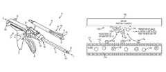
- FIG. 1is a perspective view of one exemplary embodiment of a surgical instrument having an attachment portion attached to a distal end thereof;
- FIG. 2is a perspective view of the surgical instrument of FIG. 1 with the attachment portion detached from a shaft of the instrument;
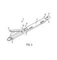
- FIG. 3is a perspective view of the attachment portion of FIG. 2 including at least one piece of adjunct material;
- FIG. 4is an exploded perspective view of the end effector of FIG. 3 with the adjunct material removed;
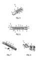
- FIG. 5is a detailed perspective view of a distal end of a staple cartridge for use with the end effector of FIG. 4 ;
- FIG. 6is a side cross-sectional view taken along the section line indicated in FIG. 5 ;
- FIG. 7is a bottom perspective view of the staple cartridge of FIG. 5 ;
- FIG. 8is a detailed perspective view of an actuation sled, pushers, and fasteners of the surgical instrument of FIG. 4 ;
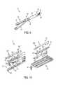
- FIG. 9is a perspective view of another exemplary embodiment of an attachment portion for use a surgical instrument.
- FIG. 10is an exploded perspective view of an end effector of the attachment portion of FIG. 9 ;
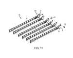
- FIG. 11is an exploded view of a drive assembly for use with the end effector of FIG. 4 ;
- FIG. 12is a perspective view of a lower jaw of the end effector of FIG. 3 ;
- FIG. 13is a perspective view of an upper jaw of the end effector of FIG. 3 , the upper jaw having an adjunct material associated therewith;
- FIG. 14is a perspective view of portions of the end effector of FIG. 2 including a retention member configured to releasably retain an adjunct material;
- FIG. 15is a perspective view of a lower jaw of the end effector of FIG. 10 ;
- FIG. 16Ais a perspective view of a cell dispersion having uncharged polymer spheres
- FIG. 16Bis a perspective view of a cell dispersion having positively charged polymer spheres.
- FIG. 17is a schematic view of an embodiment of a mechanism of electrically charged implant material enhancing healing at a wound site.
- proximal and distalare used herein with reference to a clinician manipulating the handle portion of the surgical instrument.
- proximalreferring to the portion closest to the clinician and the term “distal” referring to the portion located away from the clinician.
- distalreferring to the portion located away from the clinician.
- spatial termssuch as “vertical,” “horizontal,” “up,” and “down” may be used herein with respect to the drawings.
- surgical instrumentsare used in many orientations and positions, and these terms are not intended to be limiting and/or absolute.
- Various exemplary devices and methodsare provided for performing laparoscopic and minimally invasive surgical procedures.
- a person skilled in the artwill appreciate that the various methods and devices disclosed herein can be used in numerous surgical procedures and applications.
- the various instruments disclosed hereincan be inserted into a body in any way, such as through a natural orifice, through an incision or puncture hole formed in tissue, or through an access device, such as a trocar cannula.
- the working portions or end effector portions of the instrumentscan be inserted directly into a patient's body or can be inserted through an access device that has a working channel through which the end effector and elongated shaft of a surgical instrument can be advanced.
- adjunct materialscan be used in conjunction with surgical instruments to help improve surgical procedures.
- a person skilled in the artmay refer to these types of materials as adjunct materials.
- the end effectorcan be a surgical stapler.
- the adjunct material(s)can be disposed between and/or on jaws of the stapler, incorporated into a staple cartridge disposed in the jaws, or otherwise placed in proximity to the staples.
- the adjunct material(s)can remain at the treatment site with the staples, in turn providing a number of benefits.
- the material(s)can be used to help seal holes formed by staples as they are implanted into tissue, blood vessels, and various other objects or body parts. Further, the materials can be used to provide tissue reinforcement at the treatment site. Still further, the materials can help reduce inflammation, promote cell growth, and otherwise improve healing.
- FIGS. 1 and 2illustrate one, non-limiting exemplary embodiment of a surgical stapler 10 suitable for use with one or more adjunct materials.
- the instrument 10includes a handle assembly 12 , a shaft 14 extending distally from a distal end 12 d of the handle assembly 12 , and an attachment portion 16 removably coupled to a distal end 14 d of the shaft 14 .
- a distal end 16 d of the attachment portion 16includes an end effector 50 having jaws 52 , 54 , although other types of end effectors can be used with the shaft 14 , handle assembly 12 , and components associated with the same.
- the surgical staplerincludes opposed first and second jaws 52 , 54 with the first, lower jaw 52 including an elongate channel 56 ( FIG. 4 ) configured to support a staple cartridge 100 , and the second, upper jaw 54 having an inner surface 58 ( FIGS. 3, 4, and 6 ) that faces the lower jaw 52 and that is configured to operate as an anvil to help deploy staples of a staple cartridge.
- the jaws 52 , 54are configured to move relative to one another to clamp tissue or other objects disposed therebetween, and an axial drive assembly 80 ( FIG. 11 ) can be configured to pass through at least a portion of the end effector 50 to eject the staples into the clamped tissue.
- a knife blade 81can be associated with the axial drive assembly 80 to cut tissue during the stapling procedure.
- the handle assembly 12can have many different configurations designed to manipulate and operate the end effector associated therewith.
- the handle assembly 12has a pistol-grip type housing 18 with a variety of mechanical components disposed therein to operate various features of the instrument.
- the handle assembly 12can include mechanical components as part of a firing system actuated by a trigger 20 .
- the trigger 20can be biased to an open position with respect to a stationary handle 22 , for instance by a torsion spring, and movement of the trigger 20 toward the stationary handle 22 can actuate the firing system to cause the axial drive assembly 80 to pass through at least a portion of the end effector 50 and eject staples from a staple cartridge disposed therein.
- a torsion springactuates the firing system to cause the axial drive assembly 80 to pass through at least a portion of the end effector 50 and eject staples from a staple cartridge disposed therein.
- a rotatable knob 24can be mounted on a forward end of a barrel portion 30 of the handle assembly 12 to facilitate rotation of the shaft 14 (or the attachment portion 16 ) with respect to the handle assembly 12 around a longitudinal axis L of the shaft 14 .
- the actuation lever 26can also be mounted on a forward end of the barrel portion 30 , approximately adjacent to the rotatable knob 24 .
- the lever 26can be manipulated from side-to-side along a surface of the barrel portion 30 to facilitate reciprocal articulation of the end effector 50 .
- One or more retraction knobs 28can be movably positioned along the barrel portion 30 to return the drive assembly 80 to a retracted position, for example after the firing system has completed a firing stroke. As shown, the retraction knobs 28 move proximally toward a back end of the barrel portion 30 to retract components of the firing system, including the drive assembly 80 .
- a firing lockout assemblycan be configured to prevent the firing system from being actuated at an undesirable time, such as when an end effector is not fully coupled to the instrument.
- An anti-reverse clutch mechanismcan be configured to prevent components of the firing system from moving backwards when such backwards movement is undesirable, such as when the firing stroke has only been partially completed but temporarily stopped.
- An emergency return buttoncan be configured to permit components of a firing system to be retracted before a firing stroke is completed, for instance in a case where completing the firing stroke may cause tissue to be undesirably cut.
- the shaft 14can be removably coupled to the distal end 12 d of the handle assembly 12 at a proximal end 14 p of the shaft 14 , and a distal end 14 d of the shaft 14 can be configured to receive the attachment portion 16 .
- the shaft 14is generally cylindrical and elongate, although any number of shapes and configurations can be used for the shaft, depending, at least in part, on the configurations of the other instrument components with which it is used and the type of procedure in which the instrument is used.
- a distal end of one shaftcan have a particular configuration for receiving certain types of end effectors, while a distal end of another shaft can have a different configuration for receiving certain other types of end effectors.
- Components of the firing systemcan be disposed in the shaft 14 so that the components can reach the end effector 50 and drive assembly 80 to provide actuation of the same.
- the control rod 32can be advanced distally through at least a portion of the shaft 14 to cause the jaws 52 , 54 to collapse towards each other and/or to drive the drive assembly 80 distally through at least a portion of the end effector 50 .
- the shaft 14can also include one or more sensors (not shown) and related components, such as electronic components to help operate and use the sensors (not shown).
- the sensors and related componentscan be configured to communicate to a clinician the type of end effector associated with the distal end 14 d of the shaft 14 , among other parameters.
- the handle assembly 12can include one or more sensors and related components configured to communicate to a clinician the type of end effector and/or shaft associated with the distal end 12 d of the handle assembly 12 . Accordingly, because a variety of shafts can be interchangeably coupled with the handle assembly 12 and a variety of end effectors having different configurations can be interchangeably coupled with various shafts, the sensors can help a clinician know which shaft and end effector are being used.
- the information from the sensorscan help a monitoring or control system associated with the instrument know which operation and measurement parameters are relevant to a clinician based on the type of shaft and end effector coupled to the handle assembly. For example, when the end effector is a stapler, information about the number of times the drive assembly 80 is fired may be relevant, and when the end effector is another type of end effector, such as a cutting device, the distance the cutting portion traveled may be relevant.
- the systemcan convey the appropriate information to the clinician based on the end effector that is sensed.
- sensors associated with any of the end effector 50 , the attachment portion 16 , the shaft 14 , and the handle assembly 12can be configured to monitor other system parameters, and a monitoring or control system can communicate to a clinician the relevant other parameters based on the type of shaft or attachment portion associated with the handle assembly. Further details about sensors and related components, as well as monitoring and control systems, can be found in patents and patent applications incorporated by reference elsewhere in the present application.
- the attachment portion 16can include a proximal housing portion 34 at a proximal end 16 p thereof and an end effector or tool 50 at a distal end 16 d thereof.
- the proximal housing portion 34includes on a proximal end 34 p thereof engagement nubs 36 for releasably engaging the shaft 14 .
- the nubs 36form a bayonet type coupling with the distal end 14 d of the shaft 14 .
- any number of other complementary mating featurescan be used to allow the attachment portion 16 to be removably coupled to the shaft 14 .
- a distal end 34 d of the proximal housing portion 34can include a mounting assembly 40 pivotally secured thereto.
- the mounting assembly 40can be configured to receive a proximal end 50 p of the end effector 50 such that pivotal movement of the mounting assembly 40 about an axis perpendicular to the longitudinal axis of the housing portion 34 effects articulation of the end effector 50 about a pivot member or pin 42 .
- This pivotal movementcan be controlled by the actuation lever 26 of the handle assembly 28 , with components being disposed between the lever 26 and the mounting assembly 40 to allow for movement of the lever 26 to articulate the mounting assembly 40 , and thereby the end effector 50 .
- the end effector 50 of the illustrated embodimentis a surgical stapling tool having a first, lower jaw 52 that serves as a cartridge assembly or carrier and an opposed second, upper jaw 54 that serves as an anvil.
- an inner surface 58 of the second jaw 54can include a plurality of staple deforming cavities 60 and a cover plate 62 secured to a top surface 59 of the jaw 54 to define a cavity 64 therebetween.
- the cover plate 62can help to prevent pinching of tissue during clamping and firing of the surgical stapler.
- the cavity 64can be dimensioned to receive a distal end 80 d of the axial drive assembly 80 .
- a longitudinal slot 66can extend through the anvil portion 58 to facilitate passage of a retention flange 82 of the axial drive assembly 80 into the anvil cavity 64 .
- a camming surface 57 formed on the anvil portion 58can be positioned to engage the axial drive assembly 80 to facilitate clamping of tissue 99 .
- a pair of pivot members 53 formed on the anvil portion 54can be positioned within slots 51 formed in the carrier 52 to guide the anvil portion between the open and clamped positions.
- a pair of stabilizing memberscan engage a respective shoulder 55 formed on the carrier 52 to prevent the anvil portion 54 from sliding axially relative to the staple cartridge 100 as the camming surface 57 is deformed.
- the carrier 52 and staple cartridge 100can be pivoted between open and clamped positions while the anvil portion 54 remains substantially stationary.
- the elongated support channel 56 of the first jaw 52can be dimensioned and configured to receive a staple cartridge 100 , as shown in FIGS. 4, 5, and 7 .
- Corresponding tabs 102 and slots 68 formed along the staple cartridge 100 and the elongated support channel 56respectively, function to retain the staple cartridge 100 within the support channel 56 .
- a pair of support struts 103 formed on the staple cartridge 100can be positioned to rest on sidewalls of the carrier 52 to further stabilize the staple cartridge 100 within the support channel 56 .
- the staple cartridge 100can also include retention slots 105 for receiving a plurality of fasteners 106 and pushers 108 .
- a plurality of spaced apart longitudinal slots 107can extend through the staple cartridge 100 to accommodate upstanding cam wedges 70 of an actuation sled 72 of a firing system ( FIGS. 4 and 8 ).
- a central longitudinal slot 109can extend along the length of the staple cartridge 100 to facilitate passage of a knife blade 81 associated with the axial drive assembly 80 .
- the actuation sled 72translates through longitudinal slots 107 of the staple cartridge 100 to advance cam wedges 70 into sequential contact with pushers 108 , thereby causing the pushers 108 to translate vertically within the retention slots 105 and urge the fasteners 106 from the slots 105 into the staple deforming cavities 60 of the anvil portion 54 .
- FIGS. 9 and 10An alternative embodiment of an attachment portion 16 ′ is shown in FIGS. 9 and 10 .
- the attachment portion 16 ′can include a proximal housing portion 34 ′ at a proximal end 16 p ′ thereof and an end effector or tool 50 ′ at a distal end 16 d ′ thereof.
- Nubs 36 ′can be provided to removably couple the attachment portion 16 ′ to a shaft of a surgical instrument, and a mounting assembly 40 ′ can be provided to removably and/or pivotally couple an end effector or tool 50 ′ to the proximal housing portion 34 ′.
- the end effector 50 ′can include a first, lower jaw 52 ′ that serves as a cartridge assembly, and a second, upper jaw 54 ′ that serves as an anvil portion.
- the first jaw 52 ′can have many of the same features as the first jaw 52 of FIGS. 3, 4, and 6 , and thus can include an elongated support channel 56 ′ that is dimensioned and configured to receive a staple cartridge 100 ′, and slots 68 ′ configured to correspond with tabs 102 ′ of the staple cartridge 100 ′ to retain the cartridge 100 ′ within the channel 56 ′.
- the cartridge 100 ′can include support struts 103 ′ to rest on sidewalls of the jaw 52 ′, retention slots 105 ′ for receiving a plurality of fasteners 106 ′ and pushers 108 ′, a plurality of spaced apart longitudinal slots 107 ′ to accommodate upstanding cam wedges 70 ′ of an actuation sled 72 ′ of a firing system, and a central longitudinal slot 109 ′ to facilitate passage of a knife blade 81 ′ associated with an axial drive assembly 80 ′.
- the second jaw 54 ′can include a cover plate 62 ′ secured to a top surface of the jaws to define a cavity therebetween.
- An anvil plate 58 ′can serve as the inner surface of the jaw 54 ′, and can include a longitudinal slot 66 ′ for receiving a distal end of the axial drive assembly 80 ′, and a plurality of staple deforming pockets or cavities (not shown) to form staples ejected from the cartridge 100 ′.
- the lower jaw 52 ′ containing the cartridge 100 ′is configured to pivot toward the upper jaw 54 ′ while the upper jaw 54 ′ remains substantially stationary upon actuation by a handle assembly and related components.
- the end effector and staple cartridge disposed thereinis configured to receive an axial drive assembly.
- One non-limiting exemplary embodiment of the axial drive assembly 80is illustrated in FIG. 11 .
- a distal end of a drive beam 84can be defined by a vertical support strut 86 that supports the knife blade 81 , and an abutment surface 88 configured to engage the central portion of the actuation sled 72 during a stapling procedure.
- Bottom surface 85 at the base of the abutment surface 88can be configured to receive a support member 87 slidably positioned along the bottom of the staple cartridge 100 ( FIGS. 4 and 6 ).
- the knife blade 81can be positioned to translate slightly behind the actuation sled 72 through the central longitudinal slot 109 in the staple cartridge 100 to form an incision between rows of stapled body tissue.
- the retention flange 82can project distally from the vertical strut 86 and can support a cylindrical cam roller 89 at its distal end.
- the cam roller 89can be dimensioned and configured to engage the camming surface 57 on the anvil portion 58 to clamp the anvil portion 58 against body tissue.
- the drive assembly 80can include a single drive beam, or any other number of drive beams, and the distal end of the drive beam(s) can have any number of shapes that are configured for use in the end effector through which the drive assembly is configured to travel.
- the surgical staplercan be disposed in a cannula or port and disposed at a surgical site.
- a tissue to be cut and stapledcan be placed between the jaws 52 , 54 of the surgical stapler 10 .
- Features of the stapler 10such as the rotating knob 24 and the actuation lever 26 , can be maneuvered as desired by the clinician to achieve a desired location of the jaws 52 , 54 at the surgical site and the tissue with respect to the jaws 52 , 54 .
- the trigger 20can be pulled toward the stationary handle 22 to actuate the firing system.
- the trigger 20can cause components of the firing system to operate such that the control rod 32 advances distally through at least a portion of the shaft 14 to cause at least one of the jaws 52 , 54 to collapse towards the other to clamp the tissue disposed therebetween and/or to drive the drive assembly 80 distally through at least a portion of the end effector 50 .
- a first firing of the trigger 20can cause the jaws 52 , 54 to clamp the tissue, while subsequent firings of the trigger 20 can cause the drive assembly 80 to be advanced distally through at least a portion of the end effector 50 .
- a single, subsequent firingcan fully advance the drive assembly 80 through the staple cartridge 100 to eject the staples in the row, or alternatively, the components in the handle assembly 12 can be configured such that multiple, subsequent firings are required to fully advance the drive assembly 80 through the staple cartridge 100 to eject the staples in the row. Any number of subsequent firings can be required, but in some exemplary embodiments anywhere from two to five firings can fully advance the drive assembly 80 through the staple cartridge 100 .
- the knife 81cuts tissue as the drive assembly advances distally through the end effector 50 , and thus the staple cartridge 100 disposed therein.
- a motor disposed within the handle assembly 12 and associated with a firing triggercan actuate the drive assembly 80 automatically in response to activation of the firing trigger.
- the retraction knobs 28can be advanced proximally to retract the drive assembly 80 back towards its initial position. In some configurations, the retraction knobs 28 can be used to retract the drive assembly 80 prior to fully advancing the assembly 80 through the cartridge 100 . In other embodiments retraction of the drive assembly 80 can be automated to occur after a predetermined action. For example, once the drive assembly 80 has distally advanced to its desired location, the subsequent return of the trigger 80 back to a biased open position can cause the drive assembly 80 to automatically retract. A motor and associated components, rather than retraction knobs 28 and associated components, can be used to retract the drive assembly 80 . Further, as discussed above, other features, such as a firing lockout mechanism, an anti-reverse clutch mechanism, and an emergency return button, can be relied upon during operation of the surgical stapler 10 , as would be understood by those skilled in the art.
- the illustrated embodiment of a surgical stapling instrument 10provides one of many different configurations, and associated methods of use, that can be used in conjunction with the disclosures provided herein. Additional exemplary embodiments of surgical staplers, components thereof, and their related methods of use, that can be used in accordance with the present disclosure include those devices, components, and methods provided for in U.S. Patent Application Publication No. 2012/0083835 and U.S. Patent Application Publication No. 2013/0161374, each of which is incorporated by reference herein in its entirety.
- the present disclosureprovides for the use of implantable materials, e.g., biologic materials and/or synthetic materials, collectively “adjunct materials,” in conjunction with instrument operations.
- the end effector 50can include at least one piece of adjunct material 200 , 200 ′ positioned intermediate the first and second jaw members 52 , 54 and it can be releasably retained to one of the support channel 56 and/or the anvil portion 58 .
- the releasable retentionis provided by retention members 202 , 202 ′, which are described in further detail below.
- a surface on the adjunct material 200 , 200 ′can be configured to contact tissue as the tissue is clamped between the first and second jaw members 52 , 54 .
- the adjunct materialcan be used to distribute the compressive clamping force over the tissue, remove excess fluid from the tissue, and/or improve the purchase of the staples.
- one or more pieces of adjunct materialcan be positioned within the end effector 50 .
- one piece of adjunct material 200can be attached to the staple cartridge 100 ( FIG. 12 ) and one piece of adjunct material 200 ′ can be attached to the anvil portion 58 ( FIG. 13 ).
- two pieces of adjunct material 200can be positioned on the support channel 56 and one piece of adjunct material 200 ′ can be positioned on the anvil portion 58 , for example. Any suitable number of adjunct materials can be situated within the end effector 50 .
- Adjunct material used in conjunction with the disclosures provided for hereincan have any number of configurations and properties. Generally, they can be formed from of a bioabsorbable material, a biofragmentable material, and/or a material otherwise capable of being broken down, for example, such that the adjunct material can be absorbed, fragmented, and/or broken down during the healing process.
- the adjunct materialcan include a therapeutic drug that can be configured to be released over time to aid the tissue in healing, for example.
- the adjunct materialscan include a non-absorbable and/or a material not capable of being broken down, for example.
- connection memberscan be at least partially formed from at least one of a bioabsorbable material, a biofragmentable material, and a material capable of being broken down such that the connection members can be absorbed, fragmented, and/or broken down within the body.
- the connection memberscan include a therapeutic drug that can be configured to be released over time to aid the tissue in healing, for example.
- the connection memberscan include a non-absorbable and/or a material not capable of being broken down, for example, such as a plastic.
- biodegradable synthetic absorbable polymersuch as a polydioxanone film sold under the trademark PDS® or with a Polyglycerol sebacate (PGS) film or other biodegradable films formed from PGA (Polyglycolic acid, marketed under the trade mark Vicryl), PCL (Polycaprolactone), PLA or PLLA (Polylactic acid), PHA (polyhydroxyalkanoate), PGCL (poliglecaprone 25, sold under the trademark Monocryl), PANACRYL (Ethicon, Inc., Somerville, N.J.), Polyglactin910, Poly glyconate, PGA/TMC (polyglycolide-trimethylene carbonate sold under the trademark Biosyn), polyhydroxybutyrate (PHB), poly(vinylpyrrolidone) (PVP), poly(vinyl alcohol) (PVA), or a blend of cop
- the synthetic materialcan be broken down by exposure to water such that the water attacks the linkage of a polymer of the synthetic material.
- the mechanical strengthcan become diminished, and a construct of the material can be broken down into a mushy or fractured scaffold.
- a patient's bodycan metabolize and expel the broken down materials.
- biologic derived materialsthat can be used in conjunction with the disclosures provided for herein include platelet poor plasma (PPP), platelet rich plasma (PRP), starch, chitosan, alginate, fibrin, thrombin, polysaccharide, cellulose, collagen, bovine collagen, bovine pericardium, gelatin-resorcin-formalin adhesive, oxidized cellulose, mussel-based adhesive, poly(amino acid), agarose, polyetheretherketones, amylose, hyaluronan, hyaluronic acid, whey protein, cellulose gum, starch, gelatin, silk, or other material suitable to be mixed with biological material and introduced to a wound or defect site, including combinations of materials, or any material apparent to those skilled in the art in view of the disclosures provided for herein.
- Biologic materialscan be derived from a number of sources, including from the patient in which the biologic material is to be implanted, a person that is not the patient in which
- the adjunct materialcan come pre-loaded onto the device and/or the staple cartridge, while in other instances the adjunct material can be packaged separately.
- the stapling procedurecan be carried out as known to those skilled in the art.
- the firing of the devicecan be enough to disassociate the adjunct material from the device and/or the staple cartridge, thereby requiring no further action by the clinician.
- any remaining connection or retention member associating the adjunct material with the device and/or the staple cartridgecan be removed prior to removing the instrument from the surgical site, thereby leaving the adjunct material at the surgical site.
- the materialcan be releasably coupled to at least one of a component of the end effector and the staple cartridge prior to firing the device.
- the adjunct materialmay be refrigerated, and thus removed from the refrigerator and the related packaging, and then coupled to the device using a connection or retention member as described herein or otherwise known to those skilled in the art.
- the stapling procedurecan then be carried out as known to those skilled in the art, and if necessary, the adjunct material can be disassociated with the device as described above.
- Connection or retention memberscan be used to secure, at least temporarily, one or more pieces of adjunct material onto an end effector and/or staple cartridge.
- These retention memberscan come in a variety of forms and configurations, such as one or more sutures, adhesive materials, staples, brackets, snap-on or other coupling or mating elements, etc.
- the retention memberscan be positioned proximate to one or more sides and/or ends of the adjunct material, which can help prevent the adjunct material from peeling away from the staple cartridge and/or the anvil face when the end effector is inserted through a trocar or engaged with tissue.
- the retention memberscan be used with or in the form of an adhesive suitable to releasably retain the adjunct material to the end effector, such as cyanoacrylate.
- the adhesivecan be applied to the retention members prior to the retention members being engaged with the adjunct material, staple cartridge, and/or anvil portion.
- the retention member(s)can be detached from the adjunct material and/or the end effector so that the adjunct material can stay at the surgical site when the end effector is removed.
- FIG. 12illustrates one exemplary embodiment of a connection or retention member 202 associated with the adjunct material 200 to secure the material 200 at a temporary location with respect to the lower jaw 52 of the end effector 50 .
- the adjunct material 200is disposed over the staple cartridge 100 located in the elongate channel 56 of the lower jaw 52 , and the retention member 202 extends therethrough.
- the retention member 202is in the form of a single suture stitched through multiple locations of the adjunct material 200 , or it can be multiple sutures disposed at one or more locations on the adjunct material 200 .
- the suturesare positioned at locations around a perimeter of the adjunct material 200 , and are also adjacent to a central longitudinal channel 201 formed in the adjunct material 200 .
- the channel 201can make it easier for a knife passing through the adjunct material 200 to cut the material 200 into two or more separate strips.
- a knife passing through the lower jaw 52can cut the retention member 202 at one or more locations, thereby allowing the retention member 202 to be disassociated from the adjunct material 200 and removed from the surgical site while the adjunct material 200 remains held at the surgical site by one or more staples ejected from the cartridge 100 .
- FIG. 13illustrates another embodiment of a connection or retention member 202 ′ associated with the adjunct material 200 ′ to secure the material 200 ′ at a temporary location on the end effector 50 .
- the retention member 202 ′has the same configuration as the retention member 202 in FIG. 12 , however, in this embodiment it is used to secure the material to the anvil or upper jaw 54 , rather than the cartridge or lower jaw 52 .
- FIG. 14illustrates another, non-limiting embodiment of a connection or retention member 202 ′′ used to releasably retain an adjunct material 200 ′′ to at least one of the upper jaw 54 and the lower jaw 52 .
- the retention member 202 ′′is a single suture that extends through a distal portion 200 d ′′ of the adjunct material 200 ′′ and is coupled to a proximal end 54 p of the upper jaw 54 . Terminal ends 202 t ′′ of the retention member 202 ′′ can be used to move the retention member 202 ′′ with respect to the jaws 54 , 52 . In its extended position, which is illustrated in FIG.
- the retention member 202 ′′can hold the adjunct material 200 ′′ in position as the end effector 50 is inserted into a surgical site. Thereafter, the jaws 52 , 54 of the end effector 50 can be closed onto tissue, for example, and staples from the staple cartridge 100 can be deployed through the adjunct material 200 ′′ and into the tissue. The retention member 202 ′′ can be moved into its retracted position such that the retention member 202 ′′ can be operably disengaged from the adjunct material 200 ′′. Alternatively, the retention member 202 ′′ can be retracted prior to the staples being deployed. In any event, as a result of the above, the end effector 50 can be opened and withdrawn from the surgical site leaving behind the adjunct material 200 ′′ and tissue.
- FIG. 15illustrates yet another, non-limiting embodiment of a connection or retention member 202 ′′′ for securing a location of adjunct material 200 ′′′ to an end effector.
- the adjunct material 200 ′′′ and retention member 202 ′′′are used in conjunction with the end effector 50 ′ of FIGS. 9 and 10 .
- the retention member 202 ′′′is in the form of a suture that is used to tie the adjunct material 200 ′′′ to the first, lower jaw 52 ′ at proximal and distal ends thereof 52 p ′, 52 d ′.
- FIGS. 1illustrates yet another, non-limiting embodiment of a connection or retention member 202 ′′′ for securing a location of adjunct material 200 ′′′ to an end effector.
- the adjunct material 200 ′′′ and retention member 202 ′′′are used in conjunction with the end effector 50 ′ of FIGS. 9 and 10 .
- the retention member 202 ′′′is in the form of a suture that is used to tie the
- the adjunct material 200 ′′′can also be secured to the second, upper jaw 54 ′ at proximal and distal ends thereof 54 p ′, 54 d ′.
- recessescan be formed in either or both of the jaws 52 ′, 54 ′, and either or both of the adjunct materials 200 ′′′, which can protect the retention members 202 ′′′ against unintended cutting by an outside object.
- the knife blade 81 ′ on the driver assembly 80 ′can incise the retention members 202 ′′′ as it passes through the end effector 50 ′ to release the adjunct material 200 ′′′.
- a connection or retention membercan be configured to be released from an end effector and deployed along with a piece of adjunct material.
- head portions of retention memberscan be configured to be separated from body portions of retention members such that the head portions can be deployed with the adjunct material while the body portions remain attached to the end effector.
- the entirety of the retention memberscan remain engaged with the end effector when the adjunct material is detached from the end effector.
- adjunct materials 200 , 200 ′, 200 ′′, 200 ′′′shown in FIGS. 12-15 . While in some instances adjunct materials 200 , 200 ′, 200 ′′, 200 ′′′ can be a synthetic material, a biologic material, or a combination thereof, in some exemplary embodiments the adjunct materials can include synthetic material(s) having an electrical (e.g., positive) charge.
- adjunct materialcan be configured to have such an electrical (e.g., positively) charge.
- the adjunct materialcan be formed of a synthetic material that has positively charged polymers or copolymers and/or the adjunct material can be treated such that the polymer or copolymers forming the adjunct material are substantially permanently positively charged.
- adjunct materials having at least a portion of material that is positively chargedcan be formed of and/or used in combination with any other type of adjunct material or matrix material—including but not limited to biologic materials, synthetic materials, hydrophilic materials, hydrophobic materials, bioabsorbable materials, biofragmentable materials, or combinations thereof.
- the charged particlescan be dispersed throughout the adjunct material in any known manner.
- “disperse” and conjugates thereofis used in its broadest sense to include distributed or spread over an area, which can be uniform or not, as desired.
- layers having a uniform charge, or portions thereof having a chargeare considered to be dispersed, as well as discrete particles embedded in a material are dispersed.
- the charged particlescan be dispersed throughout the entirety of the adjunct material such as by treating the entirety of the adjunct material to have a permanent positive charge—as is discussed below—or can be just on an outer surface of the adjunct material.
- portions of the adjunct materialcan be positively charged and distributed within or on the adjunct material.
- an adjunct material that is otherwise unchargedcan have a plurality of charged spheres or beads embedded or otherwise incorporated therein.
- a layer of positively charged synthetic materialcan be laminated onto or adjacent an uncharged layer of adjunct material.
- Additional embodimentscan include a bioscaffold with a positive charge on the surface of fibers that form the bioscaffold, and, alternatively, an extracellular matrix buttress material having positively charged microspheres implanted therein.
- adjunct materialcan include biologic materials, synthetic materials, hydrophilic materials, hydrophobic materials, or any other known material or combination of materials.
- a biologic layeris formed with psotively-charged synthetic spheres embedded or implanted throughout the biologic layer. It is also appreciated that any support structures or other component of an adjunct material layer can have an electrical charge.
- FIG. 16Adepicts a standard cell dispersion 1600 of a healing area 1602 that contains uncharged polymer spheres 1604 , for example as part of a polymer scaffold, and a plurality of cells 1606 . It can be seen that some of the cells 1606 adhere to the uncharged polymer spheres 1604 , however there is no appreciable accumulation of cells 1606 near the uncharged polymer spheres 1604 .
- FIG. 16Billustrates a cell dispersion 1600 ′ of healing area 1602 ′ having positively charged polymer spheres 1604 ′ and cells 1606 ′.
- cells 1606 ′are attracted into the area of the positively charged polymer sphere 1604 ′ due to the positive charge of the polymer spheres 1604 ′.
- the healing area 1602 ′i.e., a wound site
- the healing area 1602 ′can experience enhanced healing and cellular ingrowth.
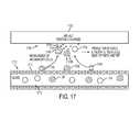
- FIG. 17shows a mechanism by which an adjunct material (“implant”) 1702 having positively charged particles can enhance healing at a wound site area 1700 .
- various cellsincluding T-cells 1704 , macrophages 1706 , and neutrophils 1708 , are present in the wound site area 1700 as these cells are typically found flowing through the circulatory system, such as in a blood vessel 1710 .
- Blood vesselsare typically lined with endothelial cells 1712 that allow blood components such as erythrocytes (not shown), fibroblasts (not shown), platelets 1714 , platelet-derived growth factor (“PDGF”) 1720 , T-cells 1704 , macrophages 1706 , and neutrophils 1708 to pass from an interior 1716 of the blood vessel 1710 through the endothelial cell lining 1712 and into the wound area 1700 .
- PDGFplatelet-derived growth factor
- the implant 1702has positively charged particles, inflammatory cells and blood components responsible for healing the wound site (which, as mentioned, can be negatively charged), including platelets 1714 , PDGF 1720 , T-cells 1704 , macrophages 1706 , and neutrophils 1708 are attracted to the implant surface 1702 and thus the wound site 1700 thereby enhancing healing relative to a system that does not have increased cell attraction.
- the positively charged implant 1702can activate tissue macrophages 1706 . When activated, macrophages 1706 release growth factors and active cytokines into the wound, providing a stimulus for cell proliferation and collagen matrix deposition, thus further enhancing healing.
- Materials that work using the positive charge mechanism described abovecan include a polysaccharide backbone (matrix) with attached functional groups, for example cellulose or dextrose gels. Additionally, a person skilled in the art will appreciate that the key to enabling desirable wound healing lies in the functional groups, which can include diethylaminoethyl and quarternay amine groups.
- adjunct materialcan have a charge induced or otherwise produced thereon.
- ECMextra cellular matrix
- any suitable method and materialcan be used.
- a permanent positive chargecan be induced or otherwise formed on at least a portion of an adjunct material, preferably at least on an outer surface of the material.
- a positively charged initiator moleculecan be used to induce a ring opening polymerization of cyclic monomers. Any known cyclic monomer can be used during synthesis of absorbable polymers and copolymers, such as glycolide, lactide, caprolactone, p-dioxanone, and combinations thereof.
- the initiator moleculescan be any positively charged molecule that initiates the ring opening polymerization of the cyclic monomer(s).
- Examples of initiator molecules that can be used to create permanent positive charge on absorbable polymersinclude 2,3-dihydroxyporpyldimethylalkylammonium chloride such as is represented by formula (I), choline such as is represented by formula (II), and choline functionalized dimethylolpropionic acid such as is represented by formula (III):
- Ris H or an alkyl chain
- a positive chargecan be created on any of the synthetic polymers or copolymers described herein, such as such as a polydioxanone film sold under the trademark PDS® or with a Polyglycerol sebacate (PGS) film or other biodegradable films formed from PGA (Polyglycolic acid, marketed under the trade mark Vicryl), PCL (Polycaprolactone), PLA or PLLA (Polylactic acid), PHA (polyhydroxyalkanoate), PGCL (poliglecaprone 25, sold under the trademark Monocryl), PANACRYL (Ethicon, Inc., Somerville, N.J.), Polyglactin910, Poly glyconate, PGA/TMC (polyglycolide-trimethylene carbonate sold under the trademark Biosyn), polyhydroxybutyrate (PHB), poly(vinylpyrrolidone) (PVP), poly(vinyl alcohol) (PVA), or a blend of copolymer
- PGAPolyglycolic
- exemplary copolymersinclude copolymers of PGA/PCL and/or PLLA/PCL, such as various polymers having PGA/PCL ratios in the range of about 25:75 to 90:10, and/or PLLC/PCL in the range of about 70:30. Additionally, in some embodiments preparation of foams via lyophilization of solutions of these polymers and/or copolymers can result in a porus matrix having a positive charge throughout the matrix.
- the devices disclosed hereincan be designed to be disposed of after a single use, or they can be designed to be used multiple times. In either case, however, the device can be reconditioned for reuse after at least one use. Reconditioning can include any combination of the steps of disassembly of the device, followed by cleaning or replacement of particular pieces, and subsequent reassembly. In particular, the device can be disassembled, and any number of the particular pieces or parts of the device can be selectively replaced or removed in any combination, e.g., electrodes, a battery or other power source, an externally wearable sensor and/or housing therefor, etc.
- the devicecan be reassembled for subsequent use either at a reconditioning facility, or by a surgical team immediately prior to a surgical procedure.
- reconditioning of a devicecan utilize a variety of techniques for disassembly, cleaning/replacement, and reassembly. Use of such techniques, and the resulting reconditioned device, are all within the scope of the present application.
- devices described hereincan be processed before surgery.
- a new or used instrumentis obtained and if necessary cleaned.
- the instrumentcan then be sterilized.
- the instrumentis placed in a closed and sealed container, such as a plastic or TYVEK bag.
- the container and instrumentare then placed in a field of radiation that can penetrate the container, such as gamma radiation, x-rays, or high-energy electrons.
- the radiationkills bacteria on the instrument and in the container.
- the sterilized instrumentcan then be stored in the sterile container.
- the sealed containerkeeps the instrument sterile until it is opened in the medical facility.
Landscapes
- Health & Medical Sciences (AREA)
- Surgery (AREA)
- Life Sciences & Earth Sciences (AREA)
- Animal Behavior & Ethology (AREA)
- Veterinary Medicine (AREA)
- Public Health (AREA)
- Heart & Thoracic Surgery (AREA)
- General Health & Medical Sciences (AREA)
- Biomedical Technology (AREA)
- Molecular Biology (AREA)
- Medical Informatics (AREA)
- Engineering & Computer Science (AREA)
- Nuclear Medicine, Radiotherapy & Molecular Imaging (AREA)
- Vascular Medicine (AREA)
- Epidemiology (AREA)
- Chemical & Material Sciences (AREA)
- Chemical Kinetics & Catalysis (AREA)
- Dispersion Chemistry (AREA)
- Surgical Instruments (AREA)
- Materials For Medical Uses (AREA)
Abstract
Description


Claims (9)
Priority Applications (8)
| Application Number | Priority Date | Filing Date | Title |
|---|---|---|---|
| US14/075,438US10456129B2 (en) | 2013-11-08 | 2013-11-08 | Positively charged implantable materials and method of forming the same |
| MX2016005987AMX375763B (en) | 2013-11-08 | 2014-10-28 | POSITIVELY CHARGED IMPLANTABLE MATERIALS AND METHODS FOR FORMING THEM. |
| PCT/US2014/062507WO2015069484A1 (en) | 2013-11-08 | 2014-10-28 | Positively charged implantable materials and method of forming the same |
| BR112016010226-6ABR112016010226B1 (en) | 2013-11-08 | 2014-10-28 | STAPLES CARTRIDGE AND ANCILLARY MATERIAL SET FOR USE WITH A SURGICAL STAPLER |
| RU2016122194ARU2676438C2 (en) | 2013-11-08 | 2014-10-28 | Staple cartridge assembly, adjunct material and tissue stapling method |
| JP2016528076AJP6437543B2 (en) | 2013-11-08 | 2014-10-28 | Positively charged implantable material and method of forming the same |
| CN201480061182.1ACN105764428B (en) | 2013-11-08 | 2014-10-28 | Positively charged implantable material and method of forming the same |
| EP14192329.2AEP2870926B1 (en) | 2013-11-08 | 2014-11-07 | Positively charged implantable materials |
Applications Claiming Priority (1)
| Application Number | Priority Date | Filing Date | Title |
|---|---|---|---|
| US14/075,438US10456129B2 (en) | 2013-11-08 | 2013-11-08 | Positively charged implantable materials and method of forming the same |
Publications (2)
| Publication Number | Publication Date |
|---|---|
| US20150133996A1 US20150133996A1 (en) | 2015-05-14 |
| US10456129B2true US10456129B2 (en) | 2019-10-29 |
Family
ID=51897453
Family Applications (1)
| Application Number | Title | Priority Date | Filing Date |
|---|---|---|---|
| US14/075,438Active2034-08-19US10456129B2 (en) | 2013-11-08 | 2013-11-08 | Positively charged implantable materials and method of forming the same |
Country Status (8)
| Country | Link |
|---|---|
| US (1) | US10456129B2 (en) |
| EP (1) | EP2870926B1 (en) |
| JP (1) | JP6437543B2 (en) |
| CN (1) | CN105764428B (en) |
| BR (1) | BR112016010226B1 (en) |
| MX (1) | MX375763B (en) |
| RU (1) | RU2676438C2 (en) |
| WO (1) | WO2015069484A1 (en) |
Cited By (36)
| Publication number | Priority date | Publication date | Assignee | Title |
|---|---|---|---|---|
| US11219451B2 (en) | 2013-11-08 | 2022-01-11 | Cilag Gmbh International | Tissue ingrowth materials and method of using the same |
| US11446027B2 (en) | 2020-11-25 | 2022-09-20 | Cilag Gmbh International | Compressible knitted adjuncts with surface features |
| US11512415B2 (en) | 2018-02-21 | 2022-11-29 | Cilag Gmbh International | Knitted tissue scaffolds |
| US11540831B1 (en) | 2021-08-12 | 2023-01-03 | Covidien Lp | Staple cartridge with actuation sled detection |
| US11576671B1 (en) | 2021-08-20 | 2023-02-14 | Covidien Lp | Small diameter linear surgical stapling apparatus |
| US11596402B2 (en) | 2014-06-10 | 2023-03-07 | Cilag Gmbh International | Adjunct materials and methods of using same in surgical methods for tissue sealing |
| US11602344B2 (en) | 2021-06-30 | 2023-03-14 | Covidien Lp | Surgical stapling apparatus with firing lockout assembly |
| US11602342B2 (en) | 2020-08-27 | 2023-03-14 | Covidien Lp | Surgical stapling device with laser probe |
| US11617579B2 (en) | 2021-06-29 | 2023-04-04 | Covidien Lp | Ultra low profile surgical stapling instrument for tissue resections |
| US11648007B2 (en) | 2020-11-25 | 2023-05-16 | Cilag Gmbh International | Compressible knitted adjuncts with varying fiber features |
| US11653922B2 (en) | 2021-09-29 | 2023-05-23 | Covidien Lp | Surgical stapling device with firing lockout mechanism |
| US11660094B2 (en) | 2021-09-29 | 2023-05-30 | Covidien Lp | Surgical fastening instrument with two-part surgical fasteners |
| US11660092B2 (en) | 2020-09-29 | 2023-05-30 | Covidien Lp | Adapter for securing loading units to handle assemblies of surgical stapling instruments |
| US11678883B2 (en) | 2020-11-25 | 2023-06-20 | Cilag Gmbh International | Compressible knitted adjuncts with varying interconnections |
| US11690617B2 (en) | 2020-11-25 | 2023-07-04 | Cilag Gmbh International | Compressible knitted adjuncts with finished edges |
| US11708652B2 (en) | 2018-02-21 | 2023-07-25 | Cilag Gmbh International | Knitted tissue scaffolds |
| US11707277B2 (en) | 2021-08-20 | 2023-07-25 | Covidien Lp | Articulating surgical stapling apparatus with pivotable knife bar guide assembly |
| US11707279B2 (en) | 2020-11-25 | 2023-07-25 | Cilag Gmbh International | Compressible knitted adjuncts with finished edges |
| US11717300B2 (en) | 2021-03-11 | 2023-08-08 | Covidien Lp | Surgical stapling apparatus with integrated visualization |
| US11849949B2 (en) | 2021-09-30 | 2023-12-26 | Covidien Lp | Surgical stapling device with firing lockout member |
| US11864761B2 (en) | 2021-09-14 | 2024-01-09 | Covidien Lp | Surgical instrument with illumination mechanism |
| USD1013171S1 (en) | 2018-02-21 | 2024-01-30 | Cilag Gmbh International | Knitted tissue scaffold |
| US11890014B2 (en) | 2020-02-14 | 2024-02-06 | Covidien Lp | Cartridge holder for surgical staples and having ridges in peripheral walls for gripping tissue |
| US11974750B2 (en) | 2021-03-26 | 2024-05-07 | Covidien Lp | Surgical staple cartridge |
| US12023028B2 (en) | 2021-08-20 | 2024-07-02 | Covidien Lp | Articulating surgical stapling apparatus with pivotable knife bar guide assembly |
| US12035909B2 (en) | 2021-10-13 | 2024-07-16 | Covidien Lp | Surgical stapling device with firing lockout mechanism |
| US12089838B2 (en) | 2020-07-21 | 2024-09-17 | Covidien Lp | Shipping cover for staple cartridge |
| US12108953B2 (en) | 2020-03-24 | 2024-10-08 | Covidien Lp | Surgical stapling device with replaceable staple cartridge |
| US12137905B2 (en) | 2022-05-16 | 2024-11-12 | Covidien Lp | Gas-powered continuous feed surgical fastening device |
| US12156651B2 (en) | 2020-02-03 | 2024-12-03 | Covidien Lp | Surgical stapling device |
| US12193666B2 (en) | 2022-05-27 | 2025-01-14 | Covidien Lp | Replaceable staple cartridge with retractable knife |
| US12220124B2 (en) | 2020-02-14 | 2025-02-11 | Covidien Lp | Surgical stapling device |
| US12268389B2 (en) | 2021-11-12 | 2025-04-08 | Covidien Lp | Surgical stapling device with firing lockout |
| US12336708B2 (en) | 2020-12-23 | 2025-06-24 | Covidien Lp | Surgical instrument including a decoupling mechanism |
| US12349902B2 (en) | 2020-07-09 | 2025-07-08 | Covidien Lp | Powered handle assembly for surgical devices |
| US12414770B2 (en) | 2021-05-21 | 2025-09-16 | Covidien Lp | Articulation assembly for a surgical device |
Families Citing this family (207)
| Publication number | Priority date | Publication date | Assignee | Title |
|---|---|---|---|---|
| EP2018248B1 (en) | 2006-05-19 | 2015-11-04 | Applied Medical Resources Corporation | Surgical stapler |
| EP2967564B1 (en) | 2013-03-14 | 2018-09-12 | Applied Medical Resources Corporation | Surgical stapler with partial pockets |
| US9820742B2 (en) | 2013-03-15 | 2017-11-21 | Applied Medical Resources Corporation | Surgical stapler with expandable jaw |
| KR102526549B1 (en) | 2013-03-15 | 2023-04-27 | 어플라이드 메디컬 리소시스 코포레이션 | Surgical stapler having actuation mechanism with rotatable shaft |
| CN105682567B (en) | 2013-11-04 | 2021-09-10 | 柯惠Lp公司 | Surgical fastener applying apparatus |
| JP6366708B2 (en) | 2013-11-04 | 2018-08-01 | コヴィディエン リミテッド パートナーシップ | Surgical fastener application device |
| CN105682568B (en) | 2013-11-04 | 2018-10-23 | 柯惠Lp公司 | Surgical fasteners bringing device |
| EP3142569B1 (en) | 2014-05-15 | 2023-12-27 | Covidien LP | Surgical fastener applying apparatus |
| ES2861258T3 (en) | 2014-06-11 | 2021-10-06 | Applied Med Resources | Circumferential Shot Surgical Stapler |
| KR102773368B1 (en) | 2014-09-15 | 2025-02-27 | 어플라이드 메디컬 리소시스 코포레이션 | Surgical stapler with self-adjusting staple height |
| US10039545B2 (en) | 2015-02-23 | 2018-08-07 | Covidien Lp | Double fire stapling |
| US10285698B2 (en) | 2015-02-26 | 2019-05-14 | Covidien Lp | Surgical apparatus |
| US10085749B2 (en) | 2015-02-26 | 2018-10-02 | Covidien Lp | Surgical apparatus with conductor strain relief |
| US10463368B2 (en) | 2015-04-10 | 2019-11-05 | Covidien Lp | Endoscopic stapler |
| CN107635481B (en) | 2015-05-25 | 2021-01-05 | 柯惠有限合伙公司 | Minor diameter surgical suturing device |
| US10349941B2 (en) | 2015-05-27 | 2019-07-16 | Covidien Lp | Multi-fire lead screw stapling device |
| US10172615B2 (en) | 2015-05-27 | 2019-01-08 | Covidien Lp | Multi-fire push rod stapling device |
| US10064622B2 (en) | 2015-07-29 | 2018-09-04 | Covidien Lp | Surgical stapling loading unit with stroke counter and lockout |
| US10045782B2 (en) | 2015-07-30 | 2018-08-14 | Covidien Lp | Surgical stapling loading unit with stroke counter and lockout |
| EP3331455B1 (en) | 2015-08-06 | 2019-10-09 | Applied Medical Resources Corporation | Surgical stapler having locking articulation joint |
| US10349938B2 (en) | 2015-08-31 | 2019-07-16 | Ethicon Llc | Surgical adjuncts with medicants affected by activator materials |
| US10279086B2 (en) | 2015-08-31 | 2019-05-07 | Ethicon Llc | Composite adjunct materials for delivering medicants |
| US10086116B2 (en) | 2015-08-31 | 2018-10-02 | Ethicon Llc | Adjunct material to provide controlled drug release |
| US11020116B2 (en) | 2015-08-31 | 2021-06-01 | Ethicon Llc | Surgical adjuncts with medicants affected by activators |
| US10569071B2 (en) | 2015-08-31 | 2020-02-25 | Ethicon Llc | Medicant eluting adjuncts and methods of using medicant eluting adjuncts |
| US9937283B2 (en) | 2015-08-31 | 2018-04-10 | Ethicon Endo-Surgery, Llc | Adjunct material to provide drug elution from vessels |
| US10111661B2 (en) | 2015-08-31 | 2018-10-30 | Ethicon Llc | Matrix metalloproteinase inhibiting adjuncts for surgical devices |
| US10188390B2 (en) | 2015-08-31 | 2019-01-29 | Ethicon Llc | Adjunct material to provide heterogeneous drug elution |
| US10172973B2 (en) | 2015-08-31 | 2019-01-08 | Ethicon Llc | Surgical adjuncts and medicants for promoting lung function |
| US10285692B2 (en) | 2015-08-31 | 2019-05-14 | Ethicon Llc | Adjuncts for surgical devices including agonists and antagonists |
| US10499913B2 (en) | 2015-08-31 | 2019-12-10 | Ethicon Llc | Tubular surgical constructs including adjunct material |
| US10130738B2 (en) | 2015-08-31 | 2018-11-20 | Ethicon Llc | Adjunct material to promote tissue growth |
| US10213520B2 (en) | 2015-08-31 | 2019-02-26 | Ethicon Llc | Surgical adjuncts having medicants controllably releasable therefrom |
| US10463366B2 (en) | 2015-08-31 | 2019-11-05 | Ethicon Llc | Adjunct materials for delivery to liver tissue |
| US10194936B2 (en) | 2015-08-31 | 2019-02-05 | Ethicon Endo-Surgery, Llc | Adjunct material for delivery to stomach tissue |
| US10245034B2 (en)* | 2015-08-31 | 2019-04-02 | Ethicon Llc | Inducing tissue adhesions using surgical adjuncts and medicants |
| US10076324B2 (en) | 2015-08-31 | 2018-09-18 | Ethicon Llc | Adjunct material to provide controlled drug elution |
| US10076329B2 (en) | 2015-08-31 | 2018-09-18 | Ethicon Llc | Adjunct material to promote tissue growth in a colon |
| US10188389B2 (en) | 2015-08-31 | 2019-01-29 | Ethicon Llc | Adjunct material for delivery to colon tissue |
| US10213204B2 (en) | 2015-10-02 | 2019-02-26 | Covidien Lp | Micro surgical instrument and loading unit for use therewith |
| US10772632B2 (en) | 2015-10-28 | 2020-09-15 | Covidien Lp | Surgical stapling device with triple leg staples |
| US10595864B2 (en) | 2015-11-24 | 2020-03-24 | Covidien Lp | Adapter assembly for interconnecting electromechanical surgical devices and surgical loading units, and surgical systems thereof |
| US10111660B2 (en) | 2015-12-03 | 2018-10-30 | Covidien Lp | Surgical stapler flexible distal tip |
| US10966717B2 (en) | 2016-01-07 | 2021-04-06 | Covidien Lp | Surgical fastener apparatus |
| US10660623B2 (en) | 2016-01-15 | 2020-05-26 | Covidien Lp | Centering mechanism for articulation joint |
| US10349937B2 (en) | 2016-02-10 | 2019-07-16 | Covidien Lp | Surgical stapler with articulation locking mechanism |
| US10420559B2 (en) | 2016-02-11 | 2019-09-24 | Covidien Lp | Surgical stapler with small diameter endoscopic portion |
| AU2017250206B2 (en) | 2016-04-12 | 2022-03-24 | Applied Medical Resources Corporation | Surgical stapler having a powered handle |
| WO2017180706A1 (en) | 2016-04-12 | 2017-10-19 | Applied Medical Resources Corporation | Surgical stapler having articulation mechanism |
| KR102388183B1 (en) | 2016-04-12 | 2022-04-19 | 어플라이드 메디컬 리소시스 코포레이션 | Reload Shaft Assembly for Surgical Stapler |
| US10561419B2 (en) | 2016-05-04 | 2020-02-18 | Covidien Lp | Powered end effector assembly with pivotable channel |
| US11065022B2 (en) | 2016-05-17 | 2021-07-20 | Covidien Lp | Cutting member for a surgical instrument |
| US10631857B2 (en) | 2016-11-04 | 2020-04-28 | Covidien Lp | Loading unit for surgical instruments with low profile pushers |
| US11642126B2 (en) | 2016-11-04 | 2023-05-09 | Covidien Lp | Surgical stapling apparatus with tissue pockets |
| US10492784B2 (en) | 2016-11-08 | 2019-12-03 | Covidien Lp | Surgical tool assembly with compact firing assembly |
| US10463371B2 (en) | 2016-11-29 | 2019-11-05 | Covidien Lp | Reload assembly with spent reload indicator |
| US10709901B2 (en) | 2017-01-05 | 2020-07-14 | Covidien Lp | Implantable fasteners, applicators, and methods for brachytherapy |
| US10952767B2 (en) | 2017-02-06 | 2021-03-23 | Covidien Lp | Connector clip for securing an introducer to a surgical fastener applying apparatus |
| US10485544B2 (en) | 2017-02-17 | 2019-11-26 | Ethicon Llc | End effector having extension features for mating with adjuncts |
| US10925601B2 (en) | 2017-02-17 | 2021-02-23 | Ethicon Llc | Surgical end effector adjunct attachment |
| US10869663B2 (en) | 2017-02-17 | 2020-12-22 | Ethicon Llc | End effector configured to mate with adjunct materials |
| US11141150B2 (en) | 2017-02-17 | 2021-10-12 | Cilag Gmbh International | Buttress loader for surgical staplers |
| US10729438B2 (en) | 2017-02-17 | 2020-08-04 | Ethicon Llc | Hybrid mechanism for attachment of an adjunct to a surgical instrument |
| US10478280B2 (en) | 2017-02-17 | 2019-11-19 | Ethicon Llc | Methods and devices for delivering and securing adjunct materials to a treatment site |
| US10881402B2 (en) | 2017-02-17 | 2021-01-05 | Ethicon Llc | Surgical end effector adjunct attachment |
| US10765426B2 (en) | 2017-02-17 | 2020-09-08 | Ethicon Llc | Systems for coupling adjuncts to an end effector |
| US20180235625A1 (en) | 2017-02-17 | 2018-08-23 | Ethicon Llc | End effector with adjunct materials |
| US10646221B2 (en) | 2017-02-17 | 2020-05-12 | Ethicon Llc | Surgical adjunct retaining mechanisms |
| US11006954B2 (en) | 2017-02-17 | 2021-05-18 | Ethicon Llc | Suction attachment of an adjunct to a surgical instrument |
| US10555734B2 (en) | 2017-02-17 | 2020-02-11 | Ethicon Llc | Methods and systems for mating constrictable adjunct materials with end effectors |
| US11202632B2 (en) | 2017-02-17 | 2021-12-21 | Cilag Gmbh International | Adjunct material with mating features |
| US10575850B2 (en) | 2017-02-17 | 2020-03-03 | Ethicon Llc | Systems for release of adjunct in a surgical stapling device |
| US10716564B2 (en) | 2017-02-17 | 2020-07-21 | Ethicon Llc | Stapling adjunct attachment |
| US10478183B2 (en) | 2017-02-17 | 2019-11-19 | Ethicon Llc | Adjunct release for surgical staplers |
| US20180235618A1 (en) | 2017-02-22 | 2018-08-23 | Covidien Lp | Loading unit for surgical instruments with low profile pushers |
| US11350915B2 (en) | 2017-02-23 | 2022-06-07 | Covidien Lp | Surgical stapler with small diameter endoscopic portion |
| US10849621B2 (en) | 2017-02-23 | 2020-12-01 | Covidien Lp | Surgical stapler with small diameter endoscopic portion |
| US10299790B2 (en) | 2017-03-03 | 2019-05-28 | Covidien Lp | Adapter with centering mechanism for articulation joint |
| US10660641B2 (en) | 2017-03-16 | 2020-05-26 | Covidien Lp | Adapter with centering mechanism for articulation joint |
| US11324502B2 (en) | 2017-05-02 | 2022-05-10 | Covidien Lp | Surgical loading unit including an articulating end effector |
| US10603035B2 (en) | 2017-05-02 | 2020-03-31 | Covidien Lp | Surgical loading unit including an articulating end effector |
| US10524784B2 (en) | 2017-05-05 | 2020-01-07 | Covidien Lp | Surgical staples with expandable backspan |
| US10390826B2 (en) | 2017-05-08 | 2019-08-27 | Covidien Lp | Surgical stapling device with elongated tool assembly and methods of use |
| US10420551B2 (en) | 2017-05-30 | 2019-09-24 | Covidien Lp | Authentication and information system for reusable surgical instruments |
| US10478185B2 (en) | 2017-06-02 | 2019-11-19 | Covidien Lp | Tool assembly with minimal dead space |
| US11058804B2 (en) | 2017-06-13 | 2021-07-13 | Ethicon Llc | Surgical fastener device for the prevention of ECM degradation |
| US10939911B2 (en) | 2017-06-13 | 2021-03-09 | Ethicon Llc | Surgical stapler with end effector coating |
| US20180353174A1 (en) | 2017-06-13 | 2018-12-13 | Ethicon Llc | Surgical Stapler with Controlled Healing |
| US11484310B2 (en)* | 2017-06-28 | 2022-11-01 | Cilag Gmbh International | Surgical instrument comprising a shaft including a closure tube profile |
| US10716570B2 (en) | 2017-07-31 | 2020-07-21 | Ethicon Llc | Magnetic restraint mechanism for a sphincter assist device |
| US10405865B2 (en) | 2017-07-31 | 2019-09-10 | Ethicon Llc | Method for assisting a sphincter |
| US10729533B2 (en) | 2017-07-31 | 2020-08-04 | Ethicon Llc | Absorbable polymer with drug elution for a magnet sphincter assist device |
| US10716658B2 (en) | 2017-07-31 | 2020-07-21 | Ethicon Llc | Absorbable polymer for a magnetic sphincter assist device |
| US10722340B2 (en) | 2017-07-31 | 2020-07-28 | Ethicon Llc | Magnetic sphincter replacement device with internal seals |
| US10624636B2 (en) | 2017-08-23 | 2020-04-21 | Covidien Lp | Surgical stapling device with floating staple cartridge |
| US10806452B2 (en) | 2017-08-24 | 2020-10-20 | Covidien Lp | Loading unit for a surgical stapling instrument |
| US10925603B2 (en) | 2017-11-14 | 2021-02-23 | Covidien Lp | Reload with articulation stabilization system |
| US10863987B2 (en) | 2017-11-16 | 2020-12-15 | Covidien Lp | Surgical instrument with imaging device |
| US10945732B2 (en) | 2018-01-17 | 2021-03-16 | Covidien Lp | Surgical stapler with self-returning assembly |
| US10695140B2 (en) | 2018-02-15 | 2020-06-30 | Ethicon Llc | Near field communication between a surgical instrument and a robotic surgical system |
| US10702349B2 (en) | 2018-02-20 | 2020-07-07 | Ethicon Llc | Robotic surgical instrument communication |
| KR20250038836A (en) | 2018-02-27 | 2025-03-19 | 어플라이드 메디컬 리소시스 코포레이션 | Surgical stapler having a powered handle |
| CA3090020A1 (en) | 2018-03-02 | 2019-09-06 | Covidien Lp | Surgical stapling instrument |
| US10849622B2 (en) | 2018-06-21 | 2020-12-01 | Covidien Lp | Articulated stapling with fire lock |
| US10736631B2 (en) | 2018-08-07 | 2020-08-11 | Covidien Lp | End effector with staple cartridge ejector |
| US10849620B2 (en) | 2018-09-14 | 2020-12-01 | Covidien Lp | Connector mechanisms for surgical stapling instruments |
| US11510669B2 (en) | 2020-09-29 | 2022-11-29 | Covidien Lp | Hand-held surgical instruments |
| US11090051B2 (en) | 2018-10-23 | 2021-08-17 | Covidien Lp | Surgical stapling device with floating staple cartridge |
| US11197673B2 (en) | 2018-10-30 | 2021-12-14 | Covidien Lp | Surgical stapling instruments and end effector assemblies thereof |
| US10912563B2 (en) | 2019-01-02 | 2021-02-09 | Covidien Lp | Stapling device including tool assembly stabilizing member |
| EP3930588B1 (en) | 2019-02-27 | 2025-09-03 | Applied Medical Resources Corporation | Surgical stapling instrument having a two-position lockout mechanism |
| US11344297B2 (en) | 2019-02-28 | 2022-05-31 | Covidien Lp | Surgical stapling device with independently movable jaws |
| US11259808B2 (en) | 2019-03-13 | 2022-03-01 | Covidien Lp | Tool assemblies with a gap locking member |
| KR20210145248A (en) | 2019-03-29 | 2021-12-01 | 어플라이드 메디컬 리소시스 코포레이션 | Reload cover for surgical stapling system |
| US11284893B2 (en) | 2019-04-02 | 2022-03-29 | Covidien Lp | Stapling device with articulating tool assembly |
| US11284892B2 (en) | 2019-04-02 | 2022-03-29 | Covidien Lp | Loading unit and adapter with modified coupling assembly |
| US11241228B2 (en) | 2019-04-05 | 2022-02-08 | Covidien Lp | Surgical instrument including an adapter assembly and an articulating surgical loading unit |
| US11224424B2 (en) | 2019-08-02 | 2022-01-18 | Covidien Lp | Linear stapling device with vertically movable knife |
| MX2022003646A (en) | 2019-09-25 | 2022-07-12 | Janssen Pharmaceuticals Inc | INTERCONNECTION OF DRUG ADMINISTRATION SYSTEMS. |
| US11406385B2 (en) | 2019-10-11 | 2022-08-09 | Covidien Lp | Stapling device with a gap locking member |
| US11123068B2 (en) | 2019-11-08 | 2021-09-21 | Covidien Lp | Surgical staple cartridge |
| US11974743B2 (en) | 2019-12-02 | 2024-05-07 | Covidien Lp | Linear stapling device with a gap locking member |
| US11707274B2 (en) | 2019-12-06 | 2023-07-25 | Covidien Lp | Articulating mechanism for surgical instrument |
| US11109862B2 (en) | 2019-12-12 | 2021-09-07 | Covidien Lp | Surgical stapling device with flexible shaft |
| US12383260B2 (en) | 2019-12-13 | 2025-08-12 | Covidien Lp | Surgical stapler with universal tip reload |
| US11737747B2 (en) | 2019-12-17 | 2023-08-29 | Covidien Lp | Hand-held surgical instruments |
| US11963711B2 (en) | 2019-12-31 | 2024-04-23 | Applied Medical Resources Corporation | Electrosurgical system with tissue and maximum current identification |
| US11278282B2 (en) | 2020-01-31 | 2022-03-22 | Covidien Lp | Stapling device with selective cutting |
| US11452524B2 (en) | 2020-01-31 | 2022-09-27 | Covidien Lp | Surgical stapling device with lockout |
| US11344301B2 (en) | 2020-03-02 | 2022-05-31 | Covidien Lp | Surgical stapling device with replaceable reload assembly |
| US11344302B2 (en) | 2020-03-05 | 2022-05-31 | Covidien Lp | Articulation mechanism for surgical stapling device |
| US11707278B2 (en) | 2020-03-06 | 2023-07-25 | Covidien Lp | Surgical stapler tool assembly to minimize bleeding |
| US11246593B2 (en) | 2020-03-06 | 2022-02-15 | Covidien Lp | Staple cartridge |
| US11357505B2 (en) | 2020-03-10 | 2022-06-14 | Covidien Lp | Surgical stapling apparatus with firing lockout mechanism |
| US11317911B2 (en) | 2020-03-10 | 2022-05-03 | Covidien Lp | Tool assembly with replaceable cartridge assembly |
| US11406383B2 (en) | 2020-03-17 | 2022-08-09 | Covidien Lp | Fire assisted powered EGIA handle |
| US11426159B2 (en) | 2020-04-01 | 2022-08-30 | Covidien Lp | Sled detection device |
| US11331098B2 (en) | 2020-04-01 | 2022-05-17 | Covidien Lp | Sled detection device |
| US11504117B2 (en) | 2020-04-02 | 2022-11-22 | Covidien Lp | Hand-held surgical instruments |
| US11607216B2 (en) | 2020-05-06 | 2023-03-21 | Janssen Pharmaceuticals, Inc. | Adaptive responses from smart packaging of drug delivery absorbable adjuncts |
| US11937794B2 (en) | 2020-05-11 | 2024-03-26 | Covidien Lp | Powered handle assembly for surgical devices |
| US11191537B1 (en) | 2020-05-12 | 2021-12-07 | Covidien Lp | Stapling device with continuously parallel jaws |
| US11406387B2 (en) | 2020-05-12 | 2022-08-09 | Covidien Lp | Surgical stapling device with replaceable staple cartridge |
| US11534167B2 (en) | 2020-05-28 | 2022-12-27 | Covidien Lp | Electrotaxis-conducive stapling |
| US11191538B1 (en) | 2020-06-08 | 2021-12-07 | Covidien Lp | Surgical stapling device with parallel jaw closure |
| US11844517B2 (en) | 2020-06-25 | 2023-12-19 | Covidien Lp | Linear stapling device with continuously parallel jaws |
| US11324500B2 (en) | 2020-06-30 | 2022-05-10 | Covidien Lp | Surgical stapling device |
| US12023027B2 (en) | 2020-07-02 | 2024-07-02 | Covidien Lp | Surgical stapling device with compressible staple cartridge |
| US11446028B2 (en) | 2020-07-09 | 2022-09-20 | Covidien Lp | Tool assembly with pivotable clamping beam |
| US11517305B2 (en) | 2020-07-09 | 2022-12-06 | Covidien Lp | Contoured staple pusher |
| US11266402B2 (en) | 2020-07-30 | 2022-03-08 | Covidien Lp | Sensing curved tip for surgical stapling instruments |
| US11439392B2 (en) | 2020-08-03 | 2022-09-13 | Covidien Lp | Surgical stapling device and fastener for pathological exam |
| US11395654B2 (en) | 2020-08-07 | 2022-07-26 | Covidien Lp | Surgical stapling device with articulation braking assembly |
| US11678878B2 (en) | 2020-09-16 | 2023-06-20 | Covidien Lp | Articulation mechanism for surgical stapling device |
| US11406384B2 (en) | 2020-10-05 | 2022-08-09 | Covidien Lp | Stapling device with drive assembly stop member |
| US11576674B2 (en) | 2020-10-06 | 2023-02-14 | Covidien Lp | Surgical stapling device with articulation lock assembly |
| KR20230096077A (en) | 2020-10-29 | 2023-06-29 | 어플라이드 메디컬 리소시스 코포레이션 | Working Shaft Retaining Mechanism for Surgical Stapler |
| US11730475B2 (en) | 2020-10-29 | 2023-08-22 | Applied Medical Resources Corporation | Surgical stapler having a powered handle |
| EP4236819A1 (en) | 2020-10-29 | 2023-09-06 | Applied Medical Resources Corporation | Material combinations and processing methods for a surgical instrument |
| US11890007B2 (en) | 2020-11-18 | 2024-02-06 | Covidien Lp | Stapling device with flex cable and tensioning mechanism |
| US11737774B2 (en) | 2020-12-04 | 2023-08-29 | Covidien Lp | Surgical instrument with articulation assembly |
| US11819200B2 (en) | 2020-12-15 | 2023-11-21 | Covidien Lp | Surgical instrument with articulation assembly |
| US11553914B2 (en) | 2020-12-22 | 2023-01-17 | Covidien Lp | Surgical stapling device with parallel jaw closure |
| US11744582B2 (en) | 2021-01-05 | 2023-09-05 | Covidien Lp | Surgical stapling device with firing lockout mechanism |
| US11759206B2 (en) | 2021-01-05 | 2023-09-19 | Covidien Lp | Surgical stapling device with firing lockout mechanism |
| US12279767B2 (en) | 2021-01-14 | 2025-04-22 | Applied Medical Resources Corporation | Surgical stapler having shaft recognition mechanism |
| US11517313B2 (en) | 2021-01-27 | 2022-12-06 | Covidien Lp | Surgical stapling device with laminated drive member |
| US11759207B2 (en) | 2021-01-27 | 2023-09-19 | Covidien Lp | Surgical stapling apparatus with adjustable height clamping member |
| US20220313262A1 (en) | 2021-03-30 | 2022-10-06 | Cilag Gmbh International | Composite adjuncts that degrade through multiple different mechanisms |
| US11602341B2 (en) | 2021-03-30 | 2023-03-14 | Cilag Gmbh International | Compressible adjuncts with drug release features |
| US11504125B2 (en) | 2021-03-30 | 2022-11-22 | Cilag Gmbh International | Tissue thickness compensating adjuncts having regions of differential expansion |
| US11849950B2 (en) | 2021-03-30 | 2023-12-26 | Cilag Gmbh International | Compressible adjuncts with drug dosage control features |
| US20220313255A1 (en) | 2021-03-30 | 2022-10-06 | Cilag Gmbh International | Smart packaging for tissue adjuncts |
| US11850332B2 (en) | 2021-03-30 | 2023-12-26 | Cilag Gmbh International | Method for treating tissue |
| US12059153B2 (en) | 2021-03-30 | 2024-08-13 | Cilag Gmbh International | Implantable adjuncts having adjustable degradation profile |
| US11627961B2 (en) | 2021-03-30 | 2023-04-18 | Cilag Gmbh International | Compressible adjuncts with different behavioral zones |
| US20220313256A1 (en) | 2021-03-30 | 2022-10-06 | Cilag Gmbh International | Passively powered packaging for tissue adjuncts |
| US11786240B2 (en) | 2021-03-30 | 2023-10-17 | Cilag Gmbh International | Using smart packaging in adjusting use of tissue adjuncts |
| US11896226B2 (en) | 2021-03-30 | 2024-02-13 | Cilag Gmbh International | Compressible adjuncts with healing-dependent degradation profile |
| US11864765B2 (en) | 2021-03-30 | 2024-01-09 | Cilag Gmbh International | Compressible adjuncts with fluid control features |
| US20220313145A1 (en) | 2021-03-30 | 2022-10-06 | Cilag Gmbh International | Monitoring healing after tissue adjunct implantation |
| US11839374B2 (en) | 2021-03-30 | 2023-12-12 | Cilag Gmbh International | Compressible adjuncts with drug release features |
| US11497495B2 (en) | 2021-03-31 | 2022-11-15 | Covidien Lp | Continuous stapler strip for use with a surgical stapling device |
| US11666330B2 (en) | 2021-04-05 | 2023-06-06 | Covidien Lp | Surgical stapling device with lockout mechanism |
| US11576670B2 (en) | 2021-05-06 | 2023-02-14 | Covidien Lp | Surgical stapling device with optimized drive assembly |
| US11812956B2 (en) | 2021-05-18 | 2023-11-14 | Covidien Lp | Dual firing radial stapling device |
| US11696755B2 (en) | 2021-05-19 | 2023-07-11 | Covidien Lp | Surgical stapling device with reload assembly removal lockout |
| US11771423B2 (en) | 2021-05-25 | 2023-10-03 | Covidien Lp | Powered stapling device with manual retraction |
| US11510673B1 (en) | 2021-05-25 | 2022-11-29 | Covidien Lp | Powered stapling device with manual retraction |
| US11701119B2 (en) | 2021-05-26 | 2023-07-18 | Covidien Lp | Powered stapling device with rack release |
| US11576675B2 (en) | 2021-06-07 | 2023-02-14 | Covidien Lp | Staple cartridge with knife |
| US11707275B2 (en) | 2021-06-29 | 2023-07-25 | Covidien Lp | Asymmetrical surgical stapling device |
| US11779334B2 (en) | 2021-08-19 | 2023-10-10 | Covidien Lp | Surgical stapling device including a manual retraction assembly |
| US12295667B2 (en) | 2021-09-29 | 2025-05-13 | Cilag Gmbh International | Surgical devices, systems, and methods using multi-source imaging |
| US12376910B2 (en) | 2021-09-29 | 2025-08-05 | Cilag Gmbh International | Methods for controlling cooperative surgical instruments |
| WO2023052941A1 (en) | 2021-09-29 | 2023-04-06 | Cilag Gmbh International | Surgical system for delivering energy to tissue in an anatomic space and monitoring a tissue parameter in a different anatomic space |
| US12364545B2 (en) | 2021-09-29 | 2025-07-22 | Cilag Gmbh International | Surgical devices, systems, and methods using fiducial identification and tracking |
| EP4221613A1 (en) | 2021-09-29 | 2023-08-09 | Cilag GmbH International | Surgical system for altering the body's sensing of food |
| JP2024536180A (en) | 2021-09-29 | 2024-10-04 | シラグ・ゲーエムベーハー・インターナショナル | Surgical devices, systems and methods for controlling one visualization with another visualization - Patents.com |
| US20230102358A1 (en) | 2021-09-29 | 2023-03-30 | Cilag Gmbh International | Surgical devices, systems, and methods using fiducial identification and tracking |
| US12290319B2 (en) | 2021-09-29 | 2025-05-06 | Cilag Gmbh International | Methods for controlling cooperative surgical instruments |
| WO2023052947A1 (en) | 2021-09-29 | 2023-04-06 | Cilag Gmbh International | Surgical devices, systems, and methods for control of one visualization with another |
| EP4271295A1 (en) | 2021-09-29 | 2023-11-08 | Cilag GmbH International | Surgical devices, systems, and methods for control of one visualization with another |
| US12137986B2 (en) | 2021-09-29 | 2024-11-12 | Cilag Gmbh International | Methods for controlling cooperative surgical instruments |
| WO2023052936A1 (en) | 2021-09-29 | 2023-04-06 | Cilag Gmbh International | Systems for controlling cooperative surgical instruments with variable surgical site access trajectories |
| US20230098670A1 (en) | 2021-09-29 | 2023-03-30 | Cilag Gmbh International | Surgical devices, systems, and methods using multi-source imaging |
| WO2023052935A1 (en) | 2021-09-29 | 2023-04-06 | Cilag Gmbh International | Surgical devices, systems, and methods for control of one visualization with another |
Citations (39)
| Publication number | Priority date | Publication date | Assignee | Title |
|---|---|---|---|---|
| US5698213A (en) | 1995-03-06 | 1997-12-16 | Ethicon, Inc. | Hydrogels of absorbable polyoxaesters |
| US5700583A (en) | 1995-03-06 | 1997-12-23 | Ethicon, Inc. | Hydrogels of absorbable polyoxaesters containing amines or amido groups |
| US5866634A (en)* | 1995-09-25 | 1999-02-02 | Shin-Etsu Chemical Co., Ltd | Biodegradable polymer compositions and shrink films |
| RU2161450C1 (en) | 1999-07-22 | 2001-01-10 | Каншин Николай Николаевич | Surgical suturing device |
| US20030209835A1 (en)* | 2002-05-10 | 2003-11-13 | Iksoo Chun | Method of forming a tubular membrane on a structural frame |
| WO2004032713A2 (en) | 2002-10-04 | 2004-04-22 | Nanomatrix, Inc. | Sealants for skin and other tissues |
| US20060257458A1 (en) | 2004-10-20 | 2006-11-16 | Gorman Anne J | Reinforced absorbable multilayered hemostatis wound dressing |
| US7143925B2 (en) | 2004-07-28 | 2006-12-05 | Ethicon Endo-Surgery, Inc. | Surgical instrument incorporating EAP blocking lockout mechanism |
| US7143924B2 (en) | 2004-02-17 | 2006-12-05 | Tyco Healthcare Group Lp | Surgical stapling apparatus with locking mechanism |
| JP2008073531A (en) | 2006-09-22 | 2008-04-03 | Ethicon Endo Surgery Inc | End effector having coating layer for electrosurgical instrument |
| WO2009073854A1 (en) | 2007-12-06 | 2009-06-11 | Nanosys, Inc. | Resorbable nanoenhanced hemostatic structures and bandage materials |
| US20090234193A1 (en) | 2008-03-13 | 2009-09-17 | Ethicon Endo-Surgery, Inc. | Apparatus for keeping clean a distal scope end of a medical viewing scope |
| US20090270686A1 (en) | 2008-04-29 | 2009-10-29 | Ethicon Endo-Surgery, Inc. | Methods and devices for maintaining visibility during surgical procedures |
| US20100016888A1 (en) | 2005-05-05 | 2010-01-21 | Allison Calabrese | Surgical Gasket |
| US20100012703A1 (en) | 2005-05-05 | 2010-01-21 | Allison Calabrese | Surgical Gasket |
| US7772352B2 (en) | 2005-01-28 | 2010-08-10 | Bezwada Biomedical Llc | Bioabsorbable and biocompatible polyurethanes and polyamides for medical devices |
| CN101999931A (en) | 2010-12-10 | 2011-04-06 | 上海导向医疗系统有限公司 | Cryoablation probe shell covered by expandable hydrogel and preparation method thereof |
| US20110192882A1 (en) | 2007-03-15 | 2011-08-11 | Ethicon Endo-Surgery, Inc. | Surgical staple having an expandable portion |
| WO2011112364A1 (en) | 2010-03-09 | 2011-09-15 | Nanosys, Inc | Nanostructure-enhanced platelet binding and hemostatic materials and structures |
| US8062330B2 (en) | 2007-06-27 | 2011-11-22 | Tyco Healthcare Group Lp | Buttress and surgical stapling apparatus |
| US20120024934A1 (en) | 2010-07-30 | 2012-02-02 | Ethicon Endo-Surgery, Inc. | Transwall visualization arrangements and methods for surgical circular staplers |
| US20120080335A1 (en) | 2010-09-30 | 2012-04-05 | Ethicon Endo-Surgery, Inc. | Compressible fastener cartridge |
| US20120083835A1 (en) | 2010-09-30 | 2012-04-05 | Ethicon Endo-Surgery, Inc. | Staple cartridge comprising a tissue thickness compensator |
| US8317070B2 (en) | 2005-08-31 | 2012-11-27 | Ethicon Endo-Surgery, Inc. | Surgical stapling devices that produce formed staples having different lengths |
| US8413871B2 (en) | 2007-03-06 | 2013-04-09 | Covidien Lp | Surgical stapling apparatus |
| US20130146642A1 (en) | 2010-09-30 | 2013-06-13 | Ethicon Endo-Surgery, Inc. | Multiple thickness implantable layers for surgical stapling devices |
| US20130209659A1 (en)* | 2012-02-10 | 2013-08-15 | Covidien Lp | Buttress Composition |
| US8535640B1 (en)* | 2005-01-04 | 2013-09-17 | Gp Medical, Inc. | Pharmaceutical composition of nanoparticles |
| US20130256365A1 (en) | 2012-03-28 | 2013-10-03 | Ethicon Endo-Surgery, Inc. | Tissue thickness compensator comprised of a plurality of materials |
| US20130256377A1 (en) | 2010-09-30 | 2013-10-03 | Ethicon Endo-Surgery, Inc. | Layer comprising deployable attachment members |
| WO2013148766A2 (en) | 2011-04-29 | 2013-10-03 | Ethicon Endo-Surgery, Inc. | Tissue thickness compensator comprising at least one medicament |
| US20130256372A1 (en) | 2012-03-28 | 2013-10-03 | Ethicon Endo-Surgery, Inc. | Tissue thickness compensator comprising capsules defining a low pressure environment |
| US20130256376A1 (en) | 2012-03-28 | 2013-10-03 | Trevor J. Barton | Tissue thickness compensator having improved visibility |
| US8551058B2 (en) | 2006-05-08 | 2013-10-08 | Ethicon Endo-Surgery, Inc. | Endoscopic translumenal surgical systems |
| WO2014016819A1 (en) | 2012-07-24 | 2014-01-30 | Omrix Biopharmaceuticals Ltd. | Device and method for the application of a curable fluid composition to a bodily organ |
| US20140158741A1 (en) | 2012-12-11 | 2014-06-12 | Ethicon Endo-Surgery, Inc. | Electrosurgical end effector with tissue tacking features |
| JP2015513956A (en) | 2012-03-28 | 2015-05-18 | エシコン・エンド−サージェリィ・インコーポレイテッドEthicon Endo−Surgery,Inc. | Tissue thickness compensator with at least one drug |
| US20150173756A1 (en) | 2013-12-23 | 2015-06-25 | Ethicon Endo-Surgery, Inc. | Surgical cutting and stapling methods |
| US20150272575A1 (en) | 2014-03-26 | 2015-10-01 | Ethicon Endo-Surgery, Inc. | Surgical instrument comprising a sensor system |
Family Cites Families (1)
| Publication number | Priority date | Publication date | Assignee | Title |
|---|---|---|---|---|
| US20060063208A1 (en)* | 2004-08-02 | 2006-03-23 | Woolf Clifford J | DRG11-responsive (DRAGON) gene and uses thereof |
- 2013
- 2013-11-08USUS14/075,438patent/US10456129B2/enactiveActive
- 2014
- 2014-10-28BRBR112016010226-6Apatent/BR112016010226B1/ennot_activeIP Right Cessation
- 2014-10-28JPJP2016528076Apatent/JP6437543B2/ennot_activeExpired - Fee Related
- 2014-10-28RURU2016122194Apatent/RU2676438C2/ennot_activeIP Right Cessation
- 2014-10-28MXMX2016005987Apatent/MX375763B/enactiveIP Right Grant
- 2014-10-28WOPCT/US2014/062507patent/WO2015069484A1/enactiveApplication Filing
- 2014-10-28CNCN201480061182.1Apatent/CN105764428B/ennot_activeExpired - Fee Related
- 2014-11-07EPEP14192329.2Apatent/EP2870926B1/ennot_activeNot-in-force
Patent Citations (48)
| Publication number | Priority date | Publication date | Assignee | Title |
|---|---|---|---|---|
| US5700583A (en) | 1995-03-06 | 1997-12-23 | Ethicon, Inc. | Hydrogels of absorbable polyoxaesters containing amines or amido groups |
| US5698213A (en) | 1995-03-06 | 1997-12-16 | Ethicon, Inc. | Hydrogels of absorbable polyoxaesters |
| US5866634A (en)* | 1995-09-25 | 1999-02-02 | Shin-Etsu Chemical Co., Ltd | Biodegradable polymer compositions and shrink films |
| RU2161450C1 (en) | 1999-07-22 | 2001-01-10 | Каншин Николай Николаевич | Surgical suturing device |
| US20030209835A1 (en)* | 2002-05-10 | 2003-11-13 | Iksoo Chun | Method of forming a tubular membrane on a structural frame |
| WO2004032713A2 (en) | 2002-10-04 | 2004-04-22 | Nanomatrix, Inc. | Sealants for skin and other tissues |
| US20100291058A1 (en) | 2002-10-04 | 2010-11-18 | Virginia Commonwealth University | Sealants for Skin and Other Tissues |
| US7143924B2 (en) | 2004-02-17 | 2006-12-05 | Tyco Healthcare Group Lp | Surgical stapling apparatus with locking mechanism |
| US7143925B2 (en) | 2004-07-28 | 2006-12-05 | Ethicon Endo-Surgery, Inc. | Surgical instrument incorporating EAP blocking lockout mechanism |
| US20060257458A1 (en) | 2004-10-20 | 2006-11-16 | Gorman Anne J | Reinforced absorbable multilayered hemostatis wound dressing |
| US8535640B1 (en)* | 2005-01-04 | 2013-09-17 | Gp Medical, Inc. | Pharmaceutical composition of nanoparticles |
| US7772352B2 (en) | 2005-01-28 | 2010-08-10 | Bezwada Biomedical Llc | Bioabsorbable and biocompatible polyurethanes and polyamides for medical devices |
| US20100012703A1 (en) | 2005-05-05 | 2010-01-21 | Allison Calabrese | Surgical Gasket |
| US20100016888A1 (en) | 2005-05-05 | 2010-01-21 | Allison Calabrese | Surgical Gasket |
| US8317070B2 (en) | 2005-08-31 | 2012-11-27 | Ethicon Endo-Surgery, Inc. | Surgical stapling devices that produce formed staples having different lengths |
| US8551058B2 (en) | 2006-05-08 | 2013-10-08 | Ethicon Endo-Surgery, Inc. | Endoscopic translumenal surgical systems |
| JP2008073531A (en) | 2006-09-22 | 2008-04-03 | Ethicon Endo Surgery Inc | End effector having coating layer for electrosurgical instrument |
| US20130112733A1 (en) | 2007-03-06 | 2013-05-09 | Covidien Lp | Surgical stapling apparatus |
| US8413871B2 (en) | 2007-03-06 | 2013-04-09 | Covidien Lp | Surgical stapling apparatus |
| US20110192882A1 (en) | 2007-03-15 | 2011-08-11 | Ethicon Endo-Surgery, Inc. | Surgical staple having an expandable portion |
| US8062330B2 (en) | 2007-06-27 | 2011-11-22 | Tyco Healthcare Group Lp | Buttress and surgical stapling apparatus |
| US9005243B2 (en)* | 2007-06-27 | 2015-04-14 | Covidien Lp | Buttress and surgical stapling apparatus |
| JP2011507562A (en) | 2007-12-06 | 2011-03-10 | ナノシス・インク. | Absorbable nano-reinforced hemostatic structure and bandage material |
| WO2009073854A1 (en) | 2007-12-06 | 2009-06-11 | Nanosys, Inc. | Resorbable nanoenhanced hemostatic structures and bandage materials |
| CN101883545A (en) | 2007-12-06 | 2010-11-10 | 纳诺西斯有限公司 | Resorbable nanoenhanced hemostatic structures and bandage materials |
| US20130161374A1 (en) | 2008-02-15 | 2013-06-27 | Ethicon Endo-Surgery, Inc. | Layer arrangements for surgical staple cartridges |
| US20130153641A1 (en) | 2008-02-15 | 2013-06-20 | Ethicon Endo-Surgery, Inc. | Releasable layer of material and surgical end effector having the same |
| US20090234193A1 (en) | 2008-03-13 | 2009-09-17 | Ethicon Endo-Surgery, Inc. | Apparatus for keeping clean a distal scope end of a medical viewing scope |
| US20090270686A1 (en) | 2008-04-29 | 2009-10-29 | Ethicon Endo-Surgery, Inc. | Methods and devices for maintaining visibility during surgical procedures |
| WO2011112364A1 (en) | 2010-03-09 | 2011-09-15 | Nanosys, Inc | Nanostructure-enhanced platelet binding and hemostatic materials and structures |
| US20120024934A1 (en) | 2010-07-30 | 2012-02-02 | Ethicon Endo-Surgery, Inc. | Transwall visualization arrangements and methods for surgical circular staplers |
| US20120080335A1 (en) | 2010-09-30 | 2012-04-05 | Ethicon Endo-Surgery, Inc. | Compressible fastener cartridge |
| US20120083835A1 (en) | 2010-09-30 | 2012-04-05 | Ethicon Endo-Surgery, Inc. | Staple cartridge comprising a tissue thickness compensator |
| US8393514B2 (en) | 2010-09-30 | 2013-03-12 | Ethicon Endo-Surgery, Inc. | Selectively orientable implantable fastener cartridge |
| US20120080334A1 (en)* | 2010-09-30 | 2012-04-05 | Ethicon Endo-Surgery, Inc. | Selectively orientable implantable fastener cartridge |
| US20130146642A1 (en) | 2010-09-30 | 2013-06-13 | Ethicon Endo-Surgery, Inc. | Multiple thickness implantable layers for surgical stapling devices |
| US20130256377A1 (en) | 2010-09-30 | 2013-10-03 | Ethicon Endo-Surgery, Inc. | Layer comprising deployable attachment members |
| CN101999931A (en) | 2010-12-10 | 2011-04-06 | 上海导向医疗系统有限公司 | Cryoablation probe shell covered by expandable hydrogel and preparation method thereof |
| WO2013148766A2 (en) | 2011-04-29 | 2013-10-03 | Ethicon Endo-Surgery, Inc. | Tissue thickness compensator comprising at least one medicament |
| US20130209659A1 (en)* | 2012-02-10 | 2013-08-15 | Covidien Lp | Buttress Composition |
| US20130256365A1 (en) | 2012-03-28 | 2013-10-03 | Ethicon Endo-Surgery, Inc. | Tissue thickness compensator comprised of a plurality of materials |
| US20130256376A1 (en) | 2012-03-28 | 2013-10-03 | Trevor J. Barton | Tissue thickness compensator having improved visibility |
| US20130256372A1 (en) | 2012-03-28 | 2013-10-03 | Ethicon Endo-Surgery, Inc. | Tissue thickness compensator comprising capsules defining a low pressure environment |
| JP2015513956A (en) | 2012-03-28 | 2015-05-18 | エシコン・エンド−サージェリィ・インコーポレイテッドEthicon Endo−Surgery,Inc. | Tissue thickness compensator with at least one drug |
| WO2014016819A1 (en) | 2012-07-24 | 2014-01-30 | Omrix Biopharmaceuticals Ltd. | Device and method for the application of a curable fluid composition to a bodily organ |
| US20140158741A1 (en) | 2012-12-11 | 2014-06-12 | Ethicon Endo-Surgery, Inc. | Electrosurgical end effector with tissue tacking features |
| US20150173756A1 (en) | 2013-12-23 | 2015-06-25 | Ethicon Endo-Surgery, Inc. | Surgical cutting and stapling methods |
| US20150272575A1 (en) | 2014-03-26 | 2015-10-01 | Ethicon Endo-Surgery, Inc. | Surgical instrument comprising a sensor system |
Non-Patent Citations (24)
| Title |
|---|
| Azuma et al. (2015) "Chitin, chitosan, and its derivatives for wound healing: old and new materials," Journal of Functional Biomaterials. 6(1):104-142. |
| Chen et al. "Elastomeric Biomaterials for Tissue Engineering." Prog. Polymer. Sci. 38(2013):584-671. |
| Le, Y. et al. (Dec. 1997). "Recent Developments in Fibres and Materials for Wound Management," Indian Journal of Fibre & Textile Research 22:337-347. |
| Lim et al. "Fabrication and Evaluation of Poly(?-caprolactone)/Silk Fibroin Blend Nanofibrous Scaffold." Biopolymers. 97(2012):265-275. |
| Mogoşanu et al. (2014) "Natural and synthetic polymers for wounds and burns dressing," International Journal of Pharmaceutics. 463(2):127-136. |
| Sezer, A.D. et al. (Nov. 16, 2011). "Biopolymers as Wound Healing Materials: Challenges and New Strategies," Chapter 19 in Biomaterials Applications for Nanomedicine, Prof. R. Pignatello ed, InTech, pp. 383-414. |
| Tan, H. et al. (2010). "Injectable, Biodegradable Hydrogels for Tissue Engineering Applications," Materials 3:1746-1767. |
| U.S. Appl. No. 13/763,192, filed Feb. 8, 2013. |
| U.S. Appl. No. 14/074,810, filed Nov. 8, 2013. |
| U.S. Appl. No. 14/074,884, filed Nov. 8, 2013. |
| U.S. Appl. No. 14/074,902, filed Nov. 8, 2013. |
| U.S. Appl. No. 14/075,459, filed Nov. 8, 2013. |
| U.S. Appl. No. 14/300,793, filed Jun. 10, 2014. |
| U.S. Appl. No. 14/300,799, filed Jun. 10, 2014. |
| U.S. Appl. No. 14/300,801, filed Jun. 10, 2014. |
| U.S. Appl. No. 14/300,804, filed Jun. 10, 2014. |
| U.S. Appl. No. 14/300,807, filed Jun. 10, 2014. |
| U.S. Appl. No. 14/300,811, filed Jun. 10, 2014. |
| U.S. Appl. No. 14/300,815, filed Jun. 10, 2014. |
| U.S. Appl. No. 14/300,817, filed Jun. 10, 2014. |
| U.S. Appl. No. 14/300,819, filed Jun. 10, 2014. |
| U.S. Appl. No. 14/300,820, filed Jun. 10, 2014. |
| U.S. Appl. No. 14/300,954, filed Jun. 10, 2014. |
| Zhao et al. "Biodegradable Fibrous Scaffolds Composed of Gelatin Coated Poly(?-caprolactone) Prepared by Coaxial Elecrospinning." J. Biomed. Mater. Res. 83A(2007):372-382. |
Cited By (46)
| Publication number | Priority date | Publication date | Assignee | Title |
|---|---|---|---|---|
| US11812953B2 (en) | 2013-11-08 | 2023-11-14 | Cilag Gmbh International | Tissue ingrowth materials and method of using the same |
| US11937809B2 (en) | 2013-11-08 | 2024-03-26 | Cilag Gmbh International | Tissue ingrowth materials and method of using the same |
| US11219451B2 (en) | 2013-11-08 | 2022-01-11 | Cilag Gmbh International | Tissue ingrowth materials and method of using the same |
| US12329377B2 (en) | 2013-11-08 | 2025-06-17 | Cilag Gmbh International | Tissue ingrowth materials and method of using the same |
| US11564680B2 (en) | 2013-11-08 | 2023-01-31 | Cilag Gmbh International | Tissue ingrowth materials and method of using the same |
| US11596402B2 (en) | 2014-06-10 | 2023-03-07 | Cilag Gmbh International | Adjunct materials and methods of using same in surgical methods for tissue sealing |
| US12016560B2 (en) | 2014-06-10 | 2024-06-25 | Cilag Gmbh International | Adjunct materials and methods of using same in surgical methods for tissue sealing |
| US11607221B2 (en) | 2014-06-10 | 2023-03-21 | Cilag Gmbh International | Adjunct materials and methods of using same in surgical methods for tissue sealing |
| US11911034B2 (en) | 2014-06-10 | 2024-02-27 | Cilag Gmbh International | Adjunct materials and methods of using same in surgical methods for tissue sealing |
| US11708652B2 (en) | 2018-02-21 | 2023-07-25 | Cilag Gmbh International | Knitted tissue scaffolds |
| US11512415B2 (en) | 2018-02-21 | 2022-11-29 | Cilag Gmbh International | Knitted tissue scaffolds |
| USD1013171S1 (en) | 2018-02-21 | 2024-01-30 | Cilag Gmbh International | Knitted tissue scaffold |
| US12156651B2 (en) | 2020-02-03 | 2024-12-03 | Covidien Lp | Surgical stapling device |
| US12220124B2 (en) | 2020-02-14 | 2025-02-11 | Covidien Lp | Surgical stapling device |
| US11890014B2 (en) | 2020-02-14 | 2024-02-06 | Covidien Lp | Cartridge holder for surgical staples and having ridges in peripheral walls for gripping tissue |
| US12108953B2 (en) | 2020-03-24 | 2024-10-08 | Covidien Lp | Surgical stapling device with replaceable staple cartridge |
| US12349902B2 (en) | 2020-07-09 | 2025-07-08 | Covidien Lp | Powered handle assembly for surgical devices |
| US12089838B2 (en) | 2020-07-21 | 2024-09-17 | Covidien Lp | Shipping cover for staple cartridge |
| US11602342B2 (en) | 2020-08-27 | 2023-03-14 | Covidien Lp | Surgical stapling device with laser probe |
| US11660092B2 (en) | 2020-09-29 | 2023-05-30 | Covidien Lp | Adapter for securing loading units to handle assemblies of surgical stapling instruments |
| US11648007B2 (en) | 2020-11-25 | 2023-05-16 | Cilag Gmbh International | Compressible knitted adjuncts with varying fiber features |
| US11446027B2 (en) | 2020-11-25 | 2022-09-20 | Cilag Gmbh International | Compressible knitted adjuncts with surface features |
| US11707279B2 (en) | 2020-11-25 | 2023-07-25 | Cilag Gmbh International | Compressible knitted adjuncts with finished edges |
| US11690617B2 (en) | 2020-11-25 | 2023-07-04 | Cilag Gmbh International | Compressible knitted adjuncts with finished edges |
| US11678883B2 (en) | 2020-11-25 | 2023-06-20 | Cilag Gmbh International | Compressible knitted adjuncts with varying interconnections |
| US12220127B2 (en) | 2020-11-25 | 2025-02-11 | Cilag Gmbh International | Compressible knitted adjuncts with varying interconnections |
| US12336708B2 (en) | 2020-12-23 | 2025-06-24 | Covidien Lp | Surgical instrument including a decoupling mechanism |
| US11717300B2 (en) | 2021-03-11 | 2023-08-08 | Covidien Lp | Surgical stapling apparatus with integrated visualization |
| US11974750B2 (en) | 2021-03-26 | 2024-05-07 | Covidien Lp | Surgical staple cartridge |
| US12414770B2 (en) | 2021-05-21 | 2025-09-16 | Covidien Lp | Articulation assembly for a surgical device |
| US11617579B2 (en) | 2021-06-29 | 2023-04-04 | Covidien Lp | Ultra low profile surgical stapling instrument for tissue resections |
| US11602344B2 (en) | 2021-06-30 | 2023-03-14 | Covidien Lp | Surgical stapling apparatus with firing lockout assembly |
| US11540831B1 (en) | 2021-08-12 | 2023-01-03 | Covidien Lp | Staple cartridge with actuation sled detection |
| US11576671B1 (en) | 2021-08-20 | 2023-02-14 | Covidien Lp | Small diameter linear surgical stapling apparatus |
| US12023028B2 (en) | 2021-08-20 | 2024-07-02 | Covidien Lp | Articulating surgical stapling apparatus with pivotable knife bar guide assembly |
| US11896220B2 (en) | 2021-08-20 | 2024-02-13 | Covidien Lp | Small diameter linear surgical stapling apparatus |
| US11707277B2 (en) | 2021-08-20 | 2023-07-25 | Covidien Lp | Articulating surgical stapling apparatus with pivotable knife bar guide assembly |
| US11864761B2 (en) | 2021-09-14 | 2024-01-09 | Covidien Lp | Surgical instrument with illumination mechanism |
| US11653922B2 (en) | 2021-09-29 | 2023-05-23 | Covidien Lp | Surgical stapling device with firing lockout mechanism |
| US12156655B2 (en) | 2021-09-29 | 2024-12-03 | Covidien Lp | Surgical stapling device with firing lockout mechanism |
| US11660094B2 (en) | 2021-09-29 | 2023-05-30 | Covidien Lp | Surgical fastening instrument with two-part surgical fasteners |
| US11849949B2 (en) | 2021-09-30 | 2023-12-26 | Covidien Lp | Surgical stapling device with firing lockout member |
| US12035909B2 (en) | 2021-10-13 | 2024-07-16 | Covidien Lp | Surgical stapling device with firing lockout mechanism |
| US12268389B2 (en) | 2021-11-12 | 2025-04-08 | Covidien Lp | Surgical stapling device with firing lockout |
| US12137905B2 (en) | 2022-05-16 | 2024-11-12 | Covidien Lp | Gas-powered continuous feed surgical fastening device |
| US12193666B2 (en) | 2022-05-27 | 2025-01-14 | Covidien Lp | Replaceable staple cartridge with retractable knife |
Also Published As
| Publication number | Publication date |
|---|---|
| BR112016010226B1 (en) | 2022-02-15 |
| RU2016122194A3 (en) | 2018-06-21 |
| CN105764428A (en) | 2016-07-13 |
| BR112016010226A2 (en) | 2017-08-08 |
| MX2016005987A (en) | 2016-12-09 |
| RU2016122194A (en) | 2017-12-13 |
| RU2676438C2 (en) | 2018-12-28 |
| JP2016535628A (en) | 2016-11-17 |
| US20150133996A1 (en) | 2015-05-14 |
| JP6437543B2 (en) | 2018-12-12 |
| MX375763B (en) | 2025-03-06 |
| CN105764428B (en) | 2019-05-07 |
| EP2870926B1 (en) | 2019-01-30 |
| EP2870926A1 (en) | 2015-05-13 |
| WO2015069484A1 (en) | 2015-05-14 |
Similar Documents
| Publication | Publication Date | Title |
|---|---|---|
| US10456129B2 (en) | Positively charged implantable materials and method of forming the same | |
| US9936950B2 (en) | Hybrid adjunct materials for use in surgical stapling | |
| US9700311B2 (en) | Tissue ingrowth materials and method of using the same | |
| EP2870937B1 (en) | Sealing materials for use in surgical stapling | |
| EP2870932B1 (en) | Hybrid adjunct materials for use in surgical stapling |
Legal Events
| Date | Code | Title | Description |
|---|---|---|---|
| AS | Assignment | Owner name:ETHICON ENDO-SURGERY, INC., OHIO Free format text:ASSIGNMENT OF ASSIGNORS INTEREST;ASSIGNORS:SHELTON, FREDERICK E., IV;HENDERSON, CORTNEY E.;WIDENHOUSE, TAMARA S. V.;REEL/FRAME:031918/0355 Effective date:20131120 | |
| AS | Assignment | Owner name:ETHICON ENDO-SURGERY, LLC, PUERTO RICO Free format text:ASSIGNMENT OF ASSIGNORS INTEREST;ASSIGNOR:ETHICON ENDO-SURGERY, INC.;REEL/FRAME:037219/0677 Effective date:20151106 | |
| AS | Assignment | Owner name:ETHICON LLC, PUERTO RICO Free format text:CHANGE OF NAME;ASSIGNOR:ETHICON ENDO-SURGERY, LLC;REEL/FRAME:041828/0945 Effective date:20161230 | |
| STPP | Information on status: patent application and granting procedure in general | Free format text:DOCKETED NEW CASE - READY FOR EXAMINATION | |
| STPP | Information on status: patent application and granting procedure in general | Free format text:NOTICE OF ALLOWANCE MAILED -- APPLICATION RECEIVED IN OFFICE OF PUBLICATIONS | |
| STPP | Information on status: patent application and granting procedure in general | Free format text:PUBLICATIONS -- ISSUE FEE PAYMENT VERIFIED | |
| STCF | Information on status: patent grant | Free format text:PATENTED CASE | |
| AS | Assignment | Owner name:CILAG GMBH INTERNATIONAL, SWITZERLAND Free format text:ASSIGNMENT OF ASSIGNORS INTEREST;ASSIGNOR:ETHICON LLC;REEL/FRAME:056983/0569 Effective date:20210405 | |
| MAFP | Maintenance fee payment | Free format text:PAYMENT OF MAINTENANCE FEE, 4TH YEAR, LARGE ENTITY (ORIGINAL EVENT CODE: M1551); ENTITY STATUS OF PATENT OWNER: LARGE ENTITY Year of fee payment:4 |