US10456043B2 - Compact confocal dental scanning apparatus - Google Patents
Compact confocal dental scanning apparatusDownload PDFInfo
- Publication number
- US10456043B2 US10456043B2US15/859,010US201715859010AUS10456043B2US 10456043 B2US10456043 B2US 10456043B2US 201715859010 AUS201715859010 AUS 201715859010AUS 10456043 B2US10456043 B2US 10456043B2
- Authority
- US
- United States
- Prior art keywords
- projection
- imaging optics
- optics system
- beam splitter
- spatial pattern
- Prior art date
- Legal status (The legal status is an assumption and is not a legal conclusion. Google has not performed a legal analysis and makes no representation as to the accuracy of the status listed.)
- Active
Links
Images


Classifications
- A—HUMAN NECESSITIES
- A61—MEDICAL OR VETERINARY SCIENCE; HYGIENE
- A61B—DIAGNOSIS; SURGERY; IDENTIFICATION
- A61B5/00—Measuring for diagnostic purposes; Identification of persons
- A61B5/0059—Measuring for diagnostic purposes; Identification of persons using light, e.g. diagnosis by transillumination, diascopy, fluorescence
- A61B5/0062—Arrangements for scanning
- A61B5/0068—Confocal scanning
- A—HUMAN NECESSITIES
- A61—MEDICAL OR VETERINARY SCIENCE; HYGIENE
- A61B—DIAGNOSIS; SURGERY; IDENTIFICATION
- A61B1/00—Instruments for performing medical examinations of the interior of cavities or tubes of the body by visual or photographical inspection, e.g. endoscopes; Illuminating arrangements therefor
- A61B1/24—Instruments for performing medical examinations of the interior of cavities or tubes of the body by visual or photographical inspection, e.g. endoscopes; Illuminating arrangements therefor for the mouth, i.e. stomatoscopes, e.g. with tongue depressors; Instruments for opening or keeping open the mouth
- A61B1/247—Instruments for performing medical examinations of the interior of cavities or tubes of the body by visual or photographical inspection, e.g. endoscopes; Illuminating arrangements therefor for the mouth, i.e. stomatoscopes, e.g. with tongue depressors; Instruments for opening or keeping open the mouth with means for viewing areas outside the direct line of sight, e.g. dentists' mirrors
- A—HUMAN NECESSITIES
- A61—MEDICAL OR VETERINARY SCIENCE; HYGIENE
- A61B—DIAGNOSIS; SURGERY; IDENTIFICATION
- A61B5/00—Measuring for diagnostic purposes; Identification of persons
- A61B5/0059—Measuring for diagnostic purposes; Identification of persons using light, e.g. diagnosis by transillumination, diascopy, fluorescence
- A61B5/0082—Measuring for diagnostic purposes; Identification of persons using light, e.g. diagnosis by transillumination, diascopy, fluorescence adapted for particular medical purposes
- A61B5/0088—Measuring for diagnostic purposes; Identification of persons using light, e.g. diagnosis by transillumination, diascopy, fluorescence adapted for particular medical purposes for oral or dental tissue
- A—HUMAN NECESSITIES
- A61—MEDICAL OR VETERINARY SCIENCE; HYGIENE
- A61C—DENTISTRY; APPARATUS OR METHODS FOR ORAL OR DENTAL HYGIENE
- A61C7/00—Orthodontics, i.e. obtaining or maintaining the desired position of teeth, e.g. by straightening, evening, regulating, separating, or by correcting malocclusions
- A61C7/002—Orthodontic computer assisted systems
- A—HUMAN NECESSITIES
- A61—MEDICAL OR VETERINARY SCIENCE; HYGIENE
- A61C—DENTISTRY; APPARATUS OR METHODS FOR ORAL OR DENTAL HYGIENE
- A61C9/00—Impression cups, i.e. impression trays; Impression methods
- A61C9/004—Means or methods for taking digitized impressions
- A61C9/0046—Data acquisition means or methods
- A61C9/0053—Optical means or methods, e.g. scanning the teeth by a laser or light beam
- A61C9/006—Optical means or methods, e.g. scanning the teeth by a laser or light beam projecting one or more stripes or patterns on the teeth
- A—HUMAN NECESSITIES
- A61—MEDICAL OR VETERINARY SCIENCE; HYGIENE
- A61C—DENTISTRY; APPARATUS OR METHODS FOR ORAL OR DENTAL HYGIENE
- A61C9/00—Impression cups, i.e. impression trays; Impression methods
- A61C9/004—Means or methods for taking digitized impressions
- A61C9/0046—Data acquisition means or methods
- A61C9/0053—Optical means or methods, e.g. scanning the teeth by a laser or light beam
- A61C9/0066—Depth determination through adaptive focusing
- G—PHYSICS
- G01—MEASURING; TESTING
- G01B—MEASURING LENGTH, THICKNESS OR SIMILAR LINEAR DIMENSIONS; MEASURING ANGLES; MEASURING AREAS; MEASURING IRREGULARITIES OF SURFACES OR CONTOURS
- G01B11/00—Measuring arrangements characterised by the use of optical techniques
- G01B11/02—Measuring arrangements characterised by the use of optical techniques for measuring length, width or thickness
- G01B11/06—Measuring arrangements characterised by the use of optical techniques for measuring length, width or thickness for measuring thickness ; e.g. of sheet material
- G01B11/0608—Height gauges
- G—PHYSICS
- G01—MEASURING; TESTING
- G01B—MEASURING LENGTH, THICKNESS OR SIMILAR LINEAR DIMENSIONS; MEASURING ANGLES; MEASURING AREAS; MEASURING IRREGULARITIES OF SURFACES OR CONTOURS
- G01B11/00—Measuring arrangements characterised by the use of optical techniques
- G01B11/24—Measuring arrangements characterised by the use of optical techniques for measuring contours or curvatures
- G—PHYSICS
- G02—OPTICS
- G02B—OPTICAL ELEMENTS, SYSTEMS OR APPARATUS
- G02B21/00—Microscopes
- G02B21/0004—Microscopes specially adapted for specific applications
- G02B21/002—Scanning microscopes
- G02B21/0024—Confocal scanning microscopes (CSOMs) or confocal "macroscopes"; Accessories which are not restricted to use with CSOMs, e.g. sample holders
- G02B21/0028—Confocal scanning microscopes (CSOMs) or confocal "macroscopes"; Accessories which are not restricted to use with CSOMs, e.g. sample holders specially adapted for specific applications, e.g. for endoscopes, ophthalmoscopes, attachments to conventional microscopes
- G—PHYSICS
- G02—OPTICS
- G02B—OPTICAL ELEMENTS, SYSTEMS OR APPARATUS
- G02B21/00—Microscopes
- G02B21/36—Microscopes arranged for photographic purposes or projection purposes or digital imaging or video purposes including associated control and data processing arrangements
- G02B21/365—Control or image processing arrangements for digital or video microscopes
- G02B21/367—Control or image processing arrangements for digital or video microscopes providing an output produced by processing a plurality of individual source images, e.g. image tiling, montage, composite images, depth sectioning, image comparison
- A—HUMAN NECESSITIES
- A61—MEDICAL OR VETERINARY SCIENCE; HYGIENE
- A61B—DIAGNOSIS; SURGERY; IDENTIFICATION
- A61B5/00—Measuring for diagnostic purposes; Identification of persons
- A61B5/72—Signal processing specially adapted for physiological signals or for diagnostic purposes
- A61B5/7235—Details of waveform analysis
- A61B5/7246—Details of waveform analysis using correlation, e.g. template matching or determination of similarity
- A—HUMAN NECESSITIES
- A61—MEDICAL OR VETERINARY SCIENCE; HYGIENE
- A61C—DENTISTRY; APPARATUS OR METHODS FOR ORAL OR DENTAL HYGIENE
- A61C19/00—Dental auxiliary appliances
- A61C19/04—Measuring instruments specially adapted for dentistry
Definitions
- This disclosurerelates generally to apparatuses and methods for three dimensional (3D) scanning of objects.
- the disclosurerelates to apparatuses and methods for three dimensional (3D) scanning of teeth in a patient's mouth.
- Three dimensional scanning of an objectis valuable in many clinical applications.
- three dimensional (3D) scanning of the teethcan provide valuable information for diagnosis and treatment such as dental restorative and orthodontics indications.
- Confocal 3D scanningis one of the imaging technologies that may provide such information.
- Confocal microscopymay be used to perform three dimensional scanning by illuminating and observing a single nearly diffraction limited spot, for example, by using a spatial pinhole to eliminate out-of-focus light.
- Confocal 3D scanningcan be used to obtain images free of defocus-blur and may allow three-dimensional visualization of the object.
- Other surface topology scannershave been described, but are generally relatively bulky and may be less comfortable or may even be difficult to use.
- U.S. Pat. No. 8,878,905describes a 3D scanner for obtaining the 3D geometry of an object using confocal pattern projection techniques.
- the 3D scanner disclosed thereinuses a time varying pattern (or a segmented light source to equivalently create a time varying pattern).
- the patternis varied in time for a fixed focus plane then the in-focus regions on the object will display an oscillating pattern of light and darkness. However, the out-of-focus regions will display smaller or no contrast in the light oscillations.
- Described hereinare apparatuses and methods for confocal 3D scanning of an object, for example, at least apportion of teeth in a patient's mouth.
- the apparatuscan comprise a confocal illuminator configured to generate confocal illumination to an object.
- the confocal illuminatorcan comprise a spatial pattern disposed on a transparent base and a light source configured to provide illumination to the spatial pattern.
- the apparatuscan comprise an optical system comprising one or more lenses and having an optical axis.
- the apparatuscan comprise a depth scanning module configured to be movable along the optical axis.
- the apparatuscan further comprise a beam splitter configured to transmit light beams of the confocal illuminator to the object and reflect light beams returned from the object.
- the apparatuscan comprise an image sensor configured to receive light beams returned from the object through the beam splitter.
- the apparatuscan be configured for 3D scanning to at least a portion of the object, for example, intraoral dental 3D scanning for all derivatives of dental restorative and orthodontics indications.
- the apparatus for confocal scanning disclosed hereincan comprise a confocal illuminator, for example, an LED illuminated transparency confocal illuminator.
- the apparatuscan comprise an optical system (including projection/imaging optics) configured to illuminate the object and image the object.
- the optical systemcan comprise a projection and imaging system or subsystem and an illumination subsystem (illumination optics).
- the projection/imaging optics systemmay include optical elements (lenses) and the same optical path.
- the apparatuscan comprise a depth scanning module, which may comprise a compact linear actuator, for example, a voice coil motor (VCM).
- VCMvoice coil motor
- the apparatuscan comprise a front tip, which can include a 45 degree back heated mirror.
- the portion of the optical system between the beam splitter and the front tipcan be configured small enough to be disposed entirely into the depth scanning module. Therefore, the apparatus confocal scanning can comprise a single opto-mechanical module for imaging and depth scanning.
- the single optomechanical module integrating the optical system and the depth scanning modulecan leads to relaxed production and assembly tolerances as well as reduced manufacturing cost.
- the optical designis suitable for LED illuminated transparency, which further enables low cost manufacturing.
- the optical systemcan further comprise reduced number of lenses, for example, the optical system can comprise less than 10 lenses, less than 9 lenses, less than 5 lenses, less than 3 lenses, etc.
- the optical systemin any of the apparatuses described herein may provide an axial magnification of between 5 and 20 (e.g., 11 ⁇ ). Furthermore, the optical system disclosed herein may be less sensitive to assembly errors and thermal variations than conventional confocal optical systems because of simpler configuration.
- the apparatuscan comprise the optical system configured for maximum deviation from telecentricity towards divergent chief rays, for minimal front tip size.
- the apparatuscan have a non-telecentric configuration in object space, for example, diverging confocal beams in object space.
- the apparatuscan further comprise a polarized beam splitter for confocal junction.
- the apparatuscan be configured for drift invariant confocal conjugation.
- the apparatuscan further support monolithic confocal conjugate assembly.
- the confocal scanning apparatuscan be compact, light weighted, and low cost.
- the apparatuscan be more compact (e.g., 2 ⁇ , 3 ⁇ , or 4 ⁇ ) and lighter (e.g., 2 ⁇ or 3 ⁇ ) than a typical conventional confocal scanners having the same scanning capability.
- the apparatuscan further comprise a compact high speed image sensor.
- the apparatuscan be compact and light weighted to be handheld.
- the scan speedcan be about 5, 10, 20, 50 scans/sec or any values therebetween.
- the scan speedcan be about 10 scans/sec.
- the spatial pattern on the transparent basemay be static (e.g., not time varying).
- the transparent basemay comprise a transparency.
- the beam splittermay comprise a polarization sensitive beam splitter, wherein the spatial pattern and the transparent base are bonded onto a first side of the beam splitter, wherein the image sensor is bonded to a second side of the beam splitter perpendicular to the first side to maintain stable relative position between the image sensor and the spatial pattern.
- the confocal illuminatormay be configured such that an image of the light source is positioned at an entrance pupil of the optical system.
- the spatial patternmay be disposed at a conjugate plane of the image sensor such that a position of an image of the object is invariant to relative lateral shift of the spatial pattern to the image sensor.
- An exit pupil of the optical systemmay be disposed for maximum deviation from telecentricity towards divergent chief rays.
- the optical systemmay comprise a projection subsystem and an imaging subsystem, which may be combined into a projection/imaging system (also referred to as a projection/imaging subsystem), wherein the projection subsystem and the imaging subsystem share the one or more lenses and a same optical path between the beam splitter and the object.
- a projection/imaging systemalso referred to as a projection/imaging subsystem
- the apparatusmay further comprise a front tip.
- the optical system (projecting/imaging optics portion of the system) between the beam splitter and the front tipmay be entirely integrated into the depth scanning module to be a single opto-mechanical module.
- the front tipmay comprise a folding mirror disposed at a 45 degree to the optical axis.
- the depth scanning modulemay be configured to be movable as a unit along the optical axis for a range between 0.1 mm to 5 mm and have a depth scanning range between 5 mm to 40 mm.
- the front tipmay have a height less than 20 mm.
- the apparatusmay comprise illumination optics including a confocal illuminator configured to generate confocal illumination to the object.
- the apparatuscan also comprise projecting/imaging optics configured to project light (e.g., the transparency pattern) onto an object and to image the object; the projection/imaging optics may have an optical axis.
- the projecting/imaging optics(a portion or subsystem of the optical system) can comprise one or more lenses and an exit pupil disposed for maximum deviation from telecentricity towards divergent chief rays.
- the apparatuscan comprise a depth scanning module configured to be movable along the optical axis.
- the apparatuscan comprise a beam splitter configured to transmit light beams of the confocal illuminator to the object and reflect light beams returned from the object.
- the apparatuscan further comprise an image sensor configured to receive light beams returned from the object through the beam splitter.
- Also described herein are methods for confocal three-dimensional scanningthat may include activating a confocal illuminator configured to generate confocal illumination to an object, the confocal illuminator comprising a spatial pattern disposed on a transparent base and a light source configured to provide illumination to the spatial pattern.
- the methodcan comprise illuminating the spatial pattern, projecting the pattern onto an object and imaging the object using an optical system comprising one or more lenses and having an optical axis (e.g., the projection/imaging optics).
- the methodcan comprise scanning the object using a depth scanning module configured to be movable along the optical axis.
- the methodcan comprise transmitting light from the confocal illuminator through a beam splitter to the object (via the projection/imaging optics) and imaging light returning from the object using the imaging optics (e.g., again, via the projecting/imaging optics) and using the beam splitter to direct the returning light onto an image sensor.
- the methodcan comprise using one or more spatial patterns on the transparent base that are not time varying.
- the methodcan comprise using a spatial pattern in which the transparent base is bonded onto a first side of the beam splitter, wherein the image sensor is bonded to a second side of the beam splitter perpendicular to the first side to maintain stable relative position between the image sensor and the spatial pattern.
- the methodcan include disposing an image of the light source (after passing through the transparency pattern) at an entrance pupil of the optical system.
- the methodcan comprise disposing a spatial pattern at a conjugate plane of the image sensor such that a position of an image of the object is invariant to relative lateral shift of the spatial pattern to the image sensor.
- the methodcan comprise disposing an exit pupil of the optical system for maximum deviation from telecentricity towards divergent chief rays.
- the methodcan comprise scanning the object by moving the depth scanning as a unit along the optical axis for a range between 0.1 mm to 5 mm to have a depth scanning range between 5 mm to 40 mm.
- handheld apparatuses for confocal (three-dimensional) scanningmay be compact and lightweight, and may include an LED based emitter providing a reduced speckle noise.
- These apparatusesmay also be used without requiring precise alignment (pre-alignment) as needed in other systems in which an array of light spots is used to provide confocal imaging, having a maximal alignment error that is about 0.5 micrometers or less.
- the confocal apparatuses described hereinmay be operated without the need for such precise alignment, by using a continuous pattern instead of spots array. As described herein a simple transparency may replace the spot array used in other systems.
- these apparatusesmay require substantially fewer elements than prior art devices; the apparatuses described herein may eliminate the need for one or more of: laser, color capture auxiliary illumination, and light transmitting thermal defogging means. Further, the apparatuses described herein may have a reduced lens count (e.g., requiring fewer lenses, compared to the prior art).
- the small projection/imaging optics systemmay therefore allow a very compact apparatus, and in particular may be used with a small axial actuator, such as a compact voice coil motor (VCM).
- VCMcompact voice coil motor
- the resulting optical configurationmay be simpler and less sensitive to assembly error and thermal variations than prior art apparatuses.
- these apparatusesmay be appropriate for straightforward color implementations, without the need for a separate illumination and dichroic filter.
- handheld apparatuses for confocal scanningmay include: a light source (e.g., one or more LEDs, including white-light LEDS, and/or a light collector and/or uniformizer); a transparency having a spatial pattern disposed thereon and configured to be illuminated by the light source; a beam splitter (e.g., a polarizing beam splitter) having a first surface and a second surface and an image sensor on the second surface; an imaging optics system (which may alternatively be referred to as a projection/imaging optics subsystem in some variations) comprising an optical gain and focusing lens and an exit pupil, the imaging optics system having an optical axis; a tip front (e.g., a hollow tip front) extending from the imaging optics system in the optical axis and comprising a fold mirror at a distal end of the hollow tip front, wherein there is no optical surface between the exit pupil and the fold mirror in the optical axis; and an axial scanner coupled to the imaging optic
- a light source
- the projection/imaging optics systemmay be configured to provide a deviation from telecentricity of a chief ray between the projection/imaging optics system and the fold mirror relative to a scan field size of between 3 and 10 degrees. It was previously believed (see, e.g., U.S. Pat. No. 8,878,905) that the optical system of a scanner should be substantially telecentric (e.g., having an angle of less than 3 degrees, preferably much less) in the space of the probed object (the object being scanned).
- the apparatuses described hereinmay be non-telecentric, e.g., may deviate from telecentricity by a predetermined amount (e.g., between 3 degrees and 10 degrees, e.g., 8.5 degrees).
- the optical design of the apparatuses described hereinmay have a light source space that includes non-telecentric aperture imaging such that the entire projection/imaging optics are sufficiently compact and lightweight to be entirely translated axially (e.g., by a linear actuator/axial scanner such as VCM) to facilitate the depth scan.
- the apparatuses described hereinmay include an integrated projection/imaging optics system that is moved as a whole by the driver (axial actuator such as a VCM).
- axial actuatorsuch as a VCM
- a separate focusing elementwhich may form part of the imaging optics system
- the entire imaging optics system between the beam splitter and the hollow front tipis entirely integrated into a single opto-mechanical module that may be moved by the axial scanner.
- the transparencymay be attached to the first surface of the beam splitter (e.g., to an external surface) and/or may be integrally formed as surface in/on the beam splitter in the optical axis.
- the spatial pattern on the transparencymay be static or time varying; in some variations the spatial pattern is not time varying.
- the spatial patternmay be formed on or as part of the beam splitter or may be bonded to the first surface of the beam splitter.
- the transparencymay be bonded onto the first surface of the beam splitter and the image sensor bonded to the second surface of the beam splitter, perpendicular to the first surface to maintain stable relative position between the image sensor and the spatial pattern.
- the beam splittermay be a polarization sensitive beam splitter, and the transparency may be bonded onto the first surface of the beam splitter and the image sensor bonded to the second surface of the beam splitter, perpendicular to the first surface to maintain stable relative position between the image sensor and the spatial pattern.
- the apparatusesmay be particularly well suited for use as with three-dimensional scanning using structured light techniques and/or light-field technology.
- the patterns(static and/or time-varying) that may be used with any of these apparatuses and methods may be configured for providing structured light imaging by projecting the known pattern (e.g., grids, lines, bars, e.g., horizontal bars, arrays, etc.) and analyzing the manner in the pattern deforms when striking the target surface(s).
- the apparatusmay calculate the depth and surface information of the object(s) in the scene.
- any of these apparatusesmay be configured as structured light 3D scanners.
- the wavelengths of light usedmay be different, and different patterns of light may be applied corresponding to the different wavelengths.
- visible and/or infrared lightmay be used.
- Any of these apparatusesmay be configured as “invisible” or “imperceptible” structured light apparatuses, in which structured light is used simultaneously or concurrently without interfering with imaging at different frequencies.
- infrared light and visible lightmay be applied and detected at high (including extremely high) frame rates that alternate between two different patterns.
- the patternsmay be complimentary or opposite (e.g., in which the dark regions in a first pattern are illuminated in the second pattern). Different wavelengths of visible light may be used instead or in addition to infrared light.
- Light field imagingmay capture information about the light field emanating from a scene. For example, the intensity of light in a scene, and also the direction that the light rays are traveling in space.
- Any of the apparatuses and methods described hereinmay include an array of micro-lenses (e.g., placed in front of the one or more image sensors) to sense intensity, color, and directional information.
- a micro-lens arraycan be positioned before or behind the focal plane of the main len(s).
- a maske.g., printed film mask
- a patterned maskmay attenuate light rays rather than bending them, and the attenuation may recoverably encode the rays on the 2D sensor.
- the apparatusmay thus focus and capture conventional 2D photos at full sensor resolution, but the raw pixel values also hold a modulated 4D light field.
- the light fieldcan be recovered by rearranging tiles of a 2D Fourier transform of sensor values into 4D planes, and computing the inverse Fourier transform.
- Full resolution image informationcan be recovered for the in-focus parts of the scene.
- a broadband maskmay be placed at the lens, to allow refocused images at full sensor resolution to be computed for some surfaces (e.g., diffusely reflecting surfaces) including at particular wavelengths, such as near-IR.
- the light field informationmay be used to estimate three-dimensional (e.g., depth) information from the image.
- the apparatusmay be configured such that an image of the light source is positioned at an entrance pupil of the projection/imaging optics system.
- the entrance pupilmay be part of the projection/imaging optics system, or may be between the projection/imaging optics system and the beam splitter, or it may be separate from the projection/imaging optics system.
- the tip frontmay be configured to be removable from the rest of the apparatus, including a housing covering the light source, beam splitter, etc.
- the housingmay include a handle portion with a grip and/or user interface (controls), such as buttons, switches, etc.
- the tip frontmay be hollow, particularly along the optical axis between the exit pupil of the projection/imaging optics system and the fold mirror.
- the tip frontmay be configured to snap onto the rest of the apparatus (e.g., the housing) and/or screw, friction fit, magnetically couple, etc.
- the tip frontmay be single-use or reusable, including sterilizable (e.g., autoclavable, for example, formed of a material that may be exposed to temperatures in excess of 100° C., including 121° C.
- these apparatusesmay be configured for use with a removable/disposable sleeve that may fit over the tip front (including, in some variations but not all, over the optical exit at the distal end/side of the tip through which the teeth may be imaged).
- the fold mirrormay include a back heated defogging mirror.
- the fold mirrormay redirect the optical axis of the apparatus out of a side window/exit for imaging teeth.
- the fold mirrormay be disposed at a 45 degree to the optical axis at the distal end of the hollow front tip (or between an angle of 30° and 60°, 35° and 55°, 40° and 50°, etc.).
- the entire apparatus, and/or the hollow front tipmay be compact; generally having a size that is less than 140 mm ⁇ 20 mm ⁇ 20 mm (e.g., length, width, thickness).
- the hollow front tip portionmay be 80 mm ⁇ 16 mm ⁇ 16 mm or less (length, width, thickness).
- the projection/imaging optics systemmay be axially moved to scan an object.
- the projection/imaging optics systemmay be configured to be movable as a unit along the optical axis for a range between 0.1 mm to 5 mm and have a depth scanning range between 5 mm to 40 mm.
- the hollow front tipmay have a height of 20 mm or less (e.g., 20 mm or less, 17 mm or less, 16 mm or less, 15 mm or less, 14 mm or less, 13 mm or less, etc.).
- the Field of viewmay be between 20 ⁇ 20 mm and 12 ⁇ 12 mm (e.g., between 18 ⁇ 14 mm or between 14 ⁇ 14 mm, etc.).
- the apparatusmay be relatively lightweight.
- the apparatusmay have a total weight of 300 gram or less, e.g., 250 g or less, 200 g or less 180 g or less, etc.).
- the diameter of the projection/imaging opticsmay be 15 mm or less.
- handheld apparatuses for confocal scanningthat include: a light source; a transparency having a spatial pattern disposed thereon and configured to be illuminated by the light source; a beam splitter having a first outer surface to which the transparency is attached and a second outer surface and an image sensor on the second outer surface; an integrated projection/imaging optics system comprising an optical gain and focusing lens and an exit pupil, the projection/imaging optics system having an optical axis; a hollow tip front extending from the projection/imaging optics system in the optical axis and comprising a fold mirror at a distal end of the hollow tip front, wherein there is no optical surface between the exit pupil and the fold mirror in the optical axis; and an axial scanner coupled to the projection/imaging optics system and configured to move the entire projection/imaging optics system in the optical axis relative to the fold mirror; wherein the projection/imaging optics system is configured to provide a deviation from telecentricity of a chief ray between the projection/imagin
- methods for confocal three-dimensional scanningmay include using any of the apparatuses described herein for scanning.
- methods for confocal 3D scanningthat include: illuminating a spatial pattern (either static or moving) on a first side of a beam splitter and projecting the spatial pattern down an optical axis, through the beam splitter, through an projection/imaging optics system (e.g., through a projection/imaging optics subsystem, such as an integrated projection/imaging optics system comprising an optical gain and focusing lens and an exit pupil), out of the exit pupil of the projection/imaging optics system, and though a tip front extending from the projection/imaging optics system to a fold mirror at a distal end of the hollow tip front, without passing through an optical surface between the exit pupil and the fold mirror in the optical axis; projecting the spatial pattern on a target (e.g., a tooth or other dental target); transmitting light (e.g., reflected
- Scanningmay be performed by moving the entire projection/imaging optics system as a unit along the optical axis, e.g., for a range between 0.1 mm to 5 mm, to scan at a depth of scanning range between 5 mm to 40 mm. Any appropriate rate of scanning may be used, including scanning at 10 Hz or greater (e.g., 15 Hz, 20 Hz, etc.).
- the spatial patternmay be any appropriate pattern, including patterns that are time varying or not time varying.
- Illuminating the spatial patternmay comprise illuminating a transparency that is bonded onto a first side of the beam splitter.
- the image sensormay be bonded to a second side of the beam splitter perpendicular to the first side to maintain stable relative position between the image sensor and the spatial pattern.
- Any of these methodsmay also include disposing the spatial pattern at a conjugate plane of the image sensor such that a position of an image of the object is invariant to relative lateral shift of the spatial pattern to the image sensor.
- the methods described hereinmay also include disposing an image of the light source at an entrance pupil of the optical system.
- Any of these methodsmay also include disposing an exit pupil of the optical system for maximum deviation from telecentricity towards divergent chief rays.
- the methods described hereinmay include determining a confocal position by maximum correlation.
- FIG. 1schematically illustrates one example of a compact apparatus for 3D confocal scanning of an object as described herein.
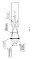
- FIG. 2schematically illustrates an example of a compact apparatus for 3D confocal scanning of an object (in this example, the light source is configured to illuminates a pattern on a transparency in Köhler illumination mode).
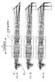
- FIG. 3Aschematically illustrates a depth scanning module of the apparatus for confocal scanning such as the apparatus shown in FIG. 1 , in a near-focus position.
- FIG. 3Bschematically illustrates the depth scanning module of the apparatus for confocal scanning such as the apparatus shown in FIG. 1 , in a mid-focus position.
- FIG. 3Cschematically illustrates the depth scanning module of the apparatus for confocal scanning such as the apparatus shown in FIG. 1 , in a far-focus position.
- FIG. 4Aillustrates an example of a compact apparatus for confocal scanning comprising a hollow front tip with a field of view (FOV) 18 ⁇ 14 mm, as described herein. Note that the dimensions provided are for illustrative purposes only.
- FIG. 4Billustrate an example of a compact apparatus for confocal scanning comprising a hollow front tip with a field of view (FOV) 14 ⁇ 14 mm, as described herein. Note that the dimensions provided are for illustrative purposes only.
- FIG. 5schematically illustrates the non-telecentricity of an optical system as described herein for a compact apparatus for confocal 3D scanning.
- FIG. 6schematically illustrates an example of a confocal focal plane module of an apparatus for confocal scanning where a transparency and image sensor are bonded directly to a beam splitter or mounted on a fixture relative to the beam splitter.
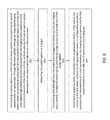
- FIG. 7Aillustrates an example of a disordered spatial pattern that may be used as part of a compact apparatus for 3D confocal scanning as described herein.
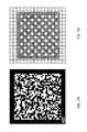
- FIG. 7Billustrates an example of an ordered spatial pattern that may be used as part of a compact apparatus for 3D confocal scanning as described herein.
- FIG. 8illustrates an example of a method for confocal three-dimensional scanning as described herein.
- confocal illuminatorconfigured to generate confocal illumination to an object.
- the confocal illuminatorcan comprise a spatial pattern disposed on a transparent base (transparency) and a light source configured to provide illumination of the spatial pattern so that it can be projected onto an object.
- the apparatuscan comprise an optical system (including projection/imaging optics) comprising one or more lenses and having an optical axis.
- the apparatusmay also include illumination optics for illuminating a pattern/transparency forming the spatial pattern.
- the apparatuscan comprise an axial scanner (e.g., a depth scanning module) that is configured to be move the projection/imaging optics system along the optical axis.
- the apparatusmay include a beam splitter configured to transmit light from the light source (after passing through the pattern) to the object and reflect light returning from the object onto an imaging sensor.
- the apparatusmay include an image sensor configured to receive light returning from the object (via the projection/imaging optics) through the beam splitter.
- the apparatuscan be configured for 3D scanning to at least a portion of the object, for example, intraoral dental 3D scanning for all derivatives of dental restorative and orthodontics indications.
- the apparatuses for confocal scanning disclosed herecan include a confocal illuminator, for example, an LED illuminated transparency confocal illuminator.
- the apparatuscan include an optical system configured project the light passing through the transparency (e.g., pattern) onto the object and image the object.
- the optical systemmay include a projection/imaging system or subsystem including projection optics and imaging optics.
- the projection optics and the imaging opticscan be configured to share the same optical elements (lenses) and the same optical path.
- the apparatuscan comprise the depth scanning module, which comprise a compact linear actuator, for example, a voice coil motor (VCM).
- VCMvoice coil motor
- the apparatuscan comprise a front tip, which can include a 45 degree back heated defogging fold mirror.
- the optical system between the beam splitter and the front tipcan be configured small enough to be disposed entirely into the depth scanning module. Therefore, the apparatus confocal scanning can comprise a single opto-mechanical module for projection, imaging and depth scanning.
- the single optomechanical module integrating the optical system and the depth scanning modulecan leads to relaxed production and assembly tolerances as well as reduced manufacturing cost.
- the optical designmay be suitable for an LED illuminated transparency, which further enables low cost manufacturing.
- the optical systemcan further therefore have a reduced lens count, for example, the optical system can comprise less than 10 lenses, less than 9 lenses, less than 5 lenses, less than 3 lenses, etc., compared to other confocal scanning systems.
- the optical system disclosed hereinmay be less sensitive to assembly errors and thermal variations than conventional confocal optical systems because of simpler configuration.
- the apparatuscan comprise the optical system configured for a desired deviation from telecentricity towards divergent chief rays, for minimal front tip size.
- the apparatuscan have a non-telecentric configuration in image and source space.
- the apparatuscan further comprise a polarized beam splitter as part of a confocal junction.
- the apparatuscan be configured for drift invariant confocal conjugation.
- the apparatuscan further support monolithic confocal conjugate assembly.
- these apparatusesmay include an integrated projection/imaging optics system in which the entire projection/imaging optics system (e.g., the projection/imaging optics subsystem) is moved axially to scan (rather than just a focusing lens).
- the entire compound projection/imaging optics systeme.g., the projection/imaging optics subsystem
- scanfarnesoid
- moving the entire compound projection/imaging optics system in order to scanis somewhat counterintuitive, it may provide a benefit in reduced overall dimension of the apparatus, particularly in combination with the a projected spatial pattern and a configuration in which the system has a deviation from telecentricity for a chief ray between the projection/imaging optics system and the fold mirror relative to a scan field size of between 3 and 10 degrees.
- these apparatusesmay be more compact (e.g., 2 ⁇ , 3 ⁇ , or 4 ⁇ ) and lighter (e.g., 2 ⁇ or 3 ⁇ ) than a typical conventional confocal scanners having the same scanning capability.
- the apparatuscan be compact and light weighted to be handheld.
- the apparatuscan further comprise a compact high speed image sensor.
- the scan speedcan be about 5, 10, 20, 50 scans/sec or any values therebetween.
- the scan speedcan be about 10 scans/sec.
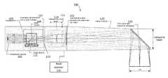
- FIG. 1schematically illustrates one example of a compact apparatus 100 for confocal scanning of an object.
- the apparatuscan comprise a confocal illuminator 101 (light source and/or illumination optics) configured to generate confocal illumination that may be projected onto an object.
- the apparatusmay include a spatial pattern disposed on a transparent base, for example, a transparency 105 or a transparent glass plate.
- the light source and any illumination opticsmay be configured to provide illumination through the spatial pattern and may include a light collector/reflector.
- the light sourcecan be an LED light source (with, e.g., a reflector behind it to direct light through the pattern).
- a conventional confocal spot array light sourcesuch as laser diode can be replaced by the LED light source.
- the apparatuscan comprise an LED based emitter, which can reduce speckle noise.
- the spatial patterncan comprise an array of segments to achieve spot illumination.
- the apparatuscan further comprise a light collector or a light uniformizer to create uniform illumination over the pattern.
- the apparatuscan further comprise a condensing lens to condense light beams of the light source.
- the apparatuscan comprise a white LED light source readily available for color model capture and rendering, which can enable straightforward color implementation.
- the apparatuscan comprise a beam splitter 109 and an image sensor 111 .
- the beam splittermay be configured to transmit light beams of the confocal illuminator to the object and reflect light beams returned from the object to the image sensor.
- the image sensor 111may be configured to receive light beams returned from the object.
- the beam splittercan be a polarization beam splitter (PBS).
- the apparatuscan comprise an optical system (including or consisting of projection/imaging optical system/subsystem 115 ) comprising one or more lenses (e.g., focusing optics 119 ), and an exit pupil 121 .
- the optical systemcan be configured to project light that passed through the transparency 105 onto the object and to image the object to the image sensor.
- the LED light sourcecan be configured to illuminates the transparency in Köhler illumination mode such that the image of the LED falls on the entrance pupil of the optical system, as shown in FIG. 2 .
- Light leaving the imaging optical system 115may pass through a hollow front tip 123 until reaching a fold mirror 125 near the distal end of the front tip 123 , and be directed out of the tip to the object (e.g., teeth); light returning from the object travels the same path.
- the front tipis hollow, and the entire imaging optical system moves relative to the front tip (e.g., there are no additional optical surfaces between the axially movable imaging optical system and the fold mirror in the front tip).
- FIG. 2which, like FIG. 1 , shows an optical system including a light source 201 (and may also include imaging optics, such as a condenser lens 203 in this example) and an optical system 207 (e.g., which may include a projection/imaging system).
- the illumination subsystemcan be configured to illuminate the pattern (e.g., the transparency 209 ) and this spatial pattern 209 may be projected onto the object.
- the illuminated objectcan be imaged back through the imaging subsystem 207 .
- the imaging subsystemcan be the same as the projection/imaging subsystem between the beam splitter and the fold mirror.
- the imaging path and the projection pathmay share the same optical path and same optical elements such as the one or more lenses, as shown in FIG. 1 .
- the objectcan be imaged back through the same optical system and light reflected from the object can be directed onto the image sensor through the beam splitter.
- the apparatus for confocal scanning disclosed hereincan be smaller, lighter and lower cost than the conventional confocal optical system.
- the imaging optical systemcan be mounted on a depth scanning module (axial scanner 135 ), as shown in FIG. 1 .
- the optical system between the beam splitter and the front tipcan be entirely integrated and coupled to the depth scanning module for axial movement relative to the front tip.
- the optical system (and in some variations the depth scanning module)can be integrated into a single optomechanical module as shown in FIG. 1 , which can lead to relaxed production and assembly tolerance.
- the axial scannercan include a linear axial actuator which can translate the optical system axially in a controlled manner, e.g., over 0.5 to 3 mm, to facilitate depth scanning.
- the apparatuscan be configured to have high axial magnification to enable simple depth scanning linear actuator.
- FIGS. 3A-3Cschematically illustrate axially scanning of the apparatus for confocal scanning in a near-focus position ( FIG. 3A ), a mid-focus position ( FIG. 3B ) and a far-focus potion (FIT> 3 C) respectively, showing the translation of the entire imaging optical system 307 , including projection/imaging optics 305 .
- the projected spatial pattern 301is transmitted onto/in the object and reflected light is received by the sensor 303 for analysis to determine the 3D surface of the object.
- the optical system including the combined projection/imaging subsystemcan result in simple projection optics (focus optics) and projection/imaging optics design and reduced the number of optical elements, such as optical lenses.
- the projection opticsmay refer to the same optics as the imaging optics but in the projection direction (e.g., from the light source onto the object).
- the optical systemcan comprise less than 10, 9, 5, or 3 optical elements.
- the optical lenses in the optical systemcan have a diameter of about 5 mm, 8 mm, 10 mm, 14 mm, 15 mm or any values therebetween, while the optical lenses in the conventional confocal optical system may have a diameter of about 25 mm.
- the optical system disclosed hereinfurther eliminated the following elements in a typical conventional confocal scanning apparatus such as dichroic filter, micro-lens, etc.
- the apparatus for confocal scanning disclosed hereinis more compact, lighter weight and lower cost than a conventional confocal scanning apparatus.
- the apparatuscan have a weight of about 100, 200 or 300 grams in some embodiments.
- the apparatuscan have a size less than 150 mm ⁇ 25 mm ⁇ 25 mm, 140 mm ⁇ 20 mm ⁇ 20 mm, or 130 mm ⁇ 14 mm ⁇ 14 mm in some embodiments.
- FIG. 4Aschematically illustrates an apparatus for compact confocal scanning comprising a hollow front tip with a field of view (FOV) 18 ⁇ 14 mm.
- FIG. 4Billustrate an apparatus for compact confocal scanning comprising a hollow front tip with a field of view (FOV) 14 ⁇ 14 mm.
- the apparatus for compact confocal scanningcan have a smaller front tip size than conventional confocal scanning apparatus.
- the apparatuscan have a front tip height of about 14 mm with a FOV of 14 ⁇ 14 mm.
- the hollow front tipcan comprise a back heated defogging fold mirror.
- the hollow tipcan have a dimension of about 90 mm ⁇ 20 mm ⁇ 20 mm, 80 mm ⁇ 16 mm ⁇ 16 mm, or 60 mm ⁇ 14 mm ⁇ 14 mm in some embodiments. These dimensions are for illustration only; other dimensions may be used.
- any of the apparatuses described hereinmay be non-telecentric.
- the projection/imaging optics systemmay be configured to provide a deviation from telecentricity of a chief ray between the projection/imaging optics system and the fold mirror relative to a scan field size of between 3 and 10 degrees.
- FIG. 5schematically illustrates an example of a non-telecentric optical system of an apparatus for confocal scanning in one embodiment of the disclosure.
- the optical systemcan be configured with the light source space non-telecentric aperture imaging such that the optical system is sufficiently compact and lightweight to be translated axially, for example, by a linear actuator such as a voice coil motor (VCM), to facilitate the depth scan.
- VCMvoice coil motor
- the exit pupil of the optical systemcan be located for maximum deviation from telecentricity towards divergent chief rays, which can enable minimal size of a front tip of the apparatus.
- the scanned field sizecan be the same for all design options, for a specific distance from the tip, for example, a mid-range of a scan depth.
- the deviation angle from telecentricitycan be determined by the exit pupil distance from the object focus and the field size.
- the tip heightcan be derived by the footprint of the beams of the light source on the folding mirror. This height can be smaller as the exit pupil gets closer to the object focus (forward exit pupil).
- Possible range of deviation angle from telecentricitycan be from about 3 degrees to about 10 degrees.
- the deviation angle from telecentricitycan be about 8.5 degrees in some embodiments.
- the deviation angle from telecentricityis for the field extent in the mirror folding plane, which has effect on the tip height.
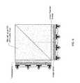
- FIG. 6schematically illustrates an example of a confocal illuminator of an apparatus for confocal scanning where a transparency (including a spatial pattern) is bonded directly to a beam splitter or mounted on a fixture relative to the beam splitter in one embodiment.
- the transparencycan be bonded directly onto one facet the beam splitter, for example, onto a first surface of a beam splitter (e.g., Polarizing Beam Splitter, PBS) while the image sensor can be bonded onto another facet (e.g., a second surface) of the beam splitter perpendicular to the transparency, thus maintaining stable relative position (“confocal condition”) between the image sensor and the transparency as shown in FIG. 6 .
- the apparatuscan be configured for drift invariant confocal conjugation.
- the transparency and the image sensorcan be disposed on conjugate planes of the object.
- the apparatuscan further support monolithic confocal conjugate assembly. Pattern based illumination enables conjugate imaging onto the image sensor, which is invariant to relative lateral shift.
- the apparatus for confocal scanningcan be configured to have position invariant correlation, which may be less sensitive to assembly drift.
- FIGS. 7A and 7Billustrates examples of spatial patterns that may be used as part of any of the compact apparatuses for 3D confocal scanning described herein.
- FIG. 7Aillustrates an example of a disordered pattern of an apparatus for confocal scanning.
- FIG. 7Billustrates an example of an ordered pattern of an apparatus for confocal scanning.
- the apparatus for confocal scanningcan comprise an illuminated pattern to replace an array of light beams in a conventional confocal scanning apparatus.
- a white LED back illuminated patterncan be used to achieve confocal imaging.
- a variety of patternscan be used in the confocal illuminator, which enables design flexibility and lower signal requirement.
- the patterncan comprise an array of segments to achieve spot-illumination equivalent.
- the illumination spots through the patterncan be nearly diffraction limited.
- the patterncan comprise an array of segments that have a size similar to pinholes in a conventional confocal microscope.
- the patterncan comprise an array of segments that have a diameter of about 1 ⁇ m, 10 ⁇ m, 25 ⁇ m, 50 ⁇ m, 1 mm or 2 mm or any values therebetween.
- the apparatus for confocal scanningcan further comprise an array of detection pinholes.
- the detection pinholescan be disposed in a fixture between the beam splitter and the image sensor.
- the detection pinholescan be bonded or integrated in the image sensor.
- the size of the pinholescan be configured adapted to the numerical aperture (NA) of the optical system and the wavelength of the light source.
- the size of the detection pinholescan be further adapted to a magnification of the optical system.
- the confocal positioncan be determination by maximum correlation.
- a reference pattern positioncan be invariant.
- a depth position per pixel or a group of pixels of the image sensorcan be assigned corresponding to the maximum signal obtained on the pixel or the group of pixels following a depth scan.
- Lateral resolutionneed not be compromised because all pixels within region of interest (ROI) can be used.
- ROIregion of interest
- resolutioncan be improved by sub-pixel processing
- the methodcan comprise activating a confocal illuminator configured to generate confocal illumination to an object.
- the methodcan comprise using the confocal illuminator comprising a spatial pattern disposed on a transparent base and a light source configured to provide illumination to the spatial pattern, and/or any additional illumination optics (e.g., lenses).
- the methodcan comprise illuminating a pattern, projecting the pattern onto an object, and imaging the object by an optical system comprising projecting/imaging optics including one or more lenses and having an optical axis.
- the methodcan comprise scanning the object by a depth scanning module configured to be movable along the optical axis.
- the methodcan comprise projecting beams of light from the confocal illuminator through a beam splitter, onto the object, and directing light returning from the object onto an imaging sensor using the beam splitter.
- the methodcan comprise using a spatial pattern on the transparent base that is not time varying.
- the methodcan comprise using the spatial pattern and the transparent base, wherein the pattern (e.g., a transparency) is bonded onto a first side of the beam splitter, further wherein the image sensor is bonded to a second side of the beam splitter perpendicular to the first side to maintain stable relative position between the image sensor and the spatial pattern.
- the patterne.g., a transparency
- a methodcan comprise disposing an image of the light source at an entrance pupil of the optical system.
- the methodcan comprise disposing the spatial pattern at a conjugate plane of the image sensor such that a position of an image of the object is invariant to relative lateral shift of the spatial pattern to the image sensor.
- the methodcan comprise disposing an exit pupil of the optical system for maximum deviation from telecentricity towards divergent chief rays.
- a methodcan comprise disposing scanning the object comprises moving the depth scanning as a unit along the optical axis for a range between 0.1 mm to 5 mm to have a depth scanning range between 5 mm to 40 mm.
- the methodcan comprise determining a confocal position by maximum correlation.
- the apparatuses and methods described hereinmay also be configured as structured light scanning systems and/or light-field 3D reconstruction systems.
- light field datamay be captured, for example, by including configuring the imaging system as a plenotoptic apparatus, for example, by including a plurality of micro-lenses before or after the focal plane of the main lensing sub-system (e.g., the compact focusing optics).
- the lightmay pass through an optical surface (the micro-lenses) between the exit pupil and the fold mirror in the optical axis alternatively, the micro-lenses may from part of the compact focusing optics.
- a depth mapmay be created from the light field data, and this depth map may 8 be used to create surfaces.
- Traditional stereo imaging methodsmay be used for depth map extraction, or depth data may be extracted from light field cameras by combining two or more methods of depth estimation.
- FIG. 8illustrates another example of a method as described herein.
- the method for confocal three-dimensional scanningincludes first illuminating a spatial pattern on a first side of a beam splitter and projecting the spatial pattern down an optical axis, through the beam splitter, through an integrated projection/imaging optics system comprising an optical gain and focusing lens and an exit pupil, out of the exit pupil and though a hollow tip front extending from the projection/imaging optics system to a fold mirror at a distal end of the hollow tip front, without passing through an optical surface between the exit pupil and the fold mirror in the optical axis 801 .
- the methodthen includes projecting the spatial pattern on a target 803 and transmitting reflected light from the target back through the hollow tip, into the projection/imaging optics system, through the beam splitter and into an image sensor on a second side of the beam splitter 805 .
- the methodmay also include scanning the target by axially moving the entire projection/imaging optics system in the optical axis relative to the fold mirror 807 , wherein the projection/imaging optics system is configured to provide a deviation from telecentricity of a chief ray between the projection/imaging optics system and the fold mirror relative to a scan field size of between 3 and 10 degrees.
- the systems, devices, and methods of the preferred embodiments and variations thereofcan be embodied and/or implemented at least in part as a machine configured to receive a computer-readable medium storing computer-readable instructions.
- the instructionsare preferably executed by computer-executable components preferably integrated with the system including the computing device configured with software.
- the computer-readable mediumcan be stored on any suitable computer-readable media such as RAMs, ROMs, flash memory, EEPROMs, optical devices (e.g., CD or DVD), hard drives, floppy drives, or any suitable device.
- the computer-executable componentis preferably a general or application-specific processor, but any suitable dedicated hardware or hardware/firmware combination can alternatively or additionally execute the instructions.
- references to a structure or feature that is disposed “adjacent” another featuremay have portions that overlap or underlie the adjacent feature.
- spatially relative termssuch as “under”, “below”, “lower”, “over”, “upper” and the like, may be used herein for ease of description to describe one element or feature's relationship to another element(s) or feature(s) as illustrated in the figures. It will be understood that the spatially relative terms are intended to encompass different orientations of the device in use or operation in addition to the orientation depicted in the figures. For example, if a device in the figures is inverted, elements described as “under” or “beneath” other elements or features would then be oriented “over” the other elements or features. Thus, the exemplary term “under” can encompass both an orientation of over and under.
- the devicemay be otherwise oriented (rotated 90 degrees or at other orientations) and the spatially relative descriptors used herein interpreted accordingly.
- the terms “upwardly”, “downwardly”, “vertical”, “horizontal” and the likeare used herein for the purpose of explanation only unless specifically indicated otherwise.
- first and secondmay be used herein to describe various features/elements (including steps), these features/elements should not be limited by these terms, unless the context indicates otherwise. These terms may be used to distinguish one feature/element from another feature/element. Thus, a first feature/element discussed below could be termed a second feature/element, and similarly, a second feature/element discussed below could be termed a first feature/element without departing from the teachings of the present invention.
- any of the apparatuses and methods described hereinshould be understood to be inclusive, but all or a sub-set of the components and/or steps may alternatively be exclusive, and may be expressed as “consisting of” or alternatively “consisting essentially of” the various components, steps, sub-components or sub-steps.
- a numeric valuemay have a value that is +/ ⁇ 0.1% of the stated value (or range of values), +/ ⁇ 1% of the stated value (or range of values), +/ ⁇ 2% of the stated value (or range of values), +/ ⁇ 5% of the stated value (or range of values), +/ ⁇ 10% of the stated value (or range of values), etc.
- Any numerical values given hereinshould also be understood to include about or approximately that value, unless the context indicates otherwise. For example, if the value “10” is disclosed, then “about 10” is also disclosed. Any numerical range recited herein is intended to include all sub-ranges subsumed therein.
Landscapes
- Health & Medical Sciences (AREA)
- Physics & Mathematics (AREA)
- Life Sciences & Earth Sciences (AREA)
- General Health & Medical Sciences (AREA)
- Animal Behavior & Ethology (AREA)
- Veterinary Medicine (AREA)
- Engineering & Computer Science (AREA)
- Public Health (AREA)
- Optics & Photonics (AREA)
- Surgery (AREA)
- Dentistry (AREA)
- Oral & Maxillofacial Surgery (AREA)
- General Physics & Mathematics (AREA)
- Pathology (AREA)
- Biophysics (AREA)
- Molecular Biology (AREA)
- Biomedical Technology (AREA)
- Heart & Thoracic Surgery (AREA)
- Medical Informatics (AREA)
- Radiology & Medical Imaging (AREA)
- Analytical Chemistry (AREA)
- Chemical & Material Sciences (AREA)
- Epidemiology (AREA)
- Nuclear Medicine, Radiotherapy & Molecular Imaging (AREA)
- Multimedia (AREA)
- Audiology, Speech & Language Pathology (AREA)
- Ophthalmology & Optometry (AREA)
- Computer Vision & Pattern Recognition (AREA)
- General Engineering & Computer Science (AREA)
- Microscoopes, Condenser (AREA)
- Lenses (AREA)
- Endoscopes (AREA)
- Dental Tools And Instruments Or Auxiliary Dental Instruments (AREA)
Abstract
Description
Claims (46)
Priority Applications (10)
| Application Number | Priority Date | Filing Date | Title |
|---|---|---|---|
| US15/859,010US10456043B2 (en) | 2017-01-12 | 2017-12-29 | Compact confocal dental scanning apparatus |
| CN201880006862.1ACN110167433B (en) | 2017-01-12 | 2018-01-11 | Compact confocal dental scanner |
| CN202211551047.8ACN116172501A (en) | 2017-01-12 | 2018-01-11 | Compact confocal dental scanning device |
| PCT/US2018/013321WO2018132569A1 (en) | 2017-01-12 | 2018-01-11 | Compact confocal dental scanning apparatus |
| EP18702020.1AEP3568064B1 (en) | 2017-01-12 | 2018-01-11 | Compact confocal dental scanning apparatus |
| US16/586,744US10918286B2 (en) | 2017-01-12 | 2019-09-27 | Compact confocal dental scanning apparatus |
| US17/142,064US11357404B2 (en) | 2017-01-12 | 2021-01-05 | Component for compact dental scanning apparatus |
| US17/737,349US11712164B2 (en) | 2017-01-12 | 2022-05-05 | Intraoral scanner with moveable opto-mechanical module |
| US18/207,622US12097009B2 (en) | 2017-01-12 | 2023-06-08 | Compact intraoral 3D scanner |
| US18/806,591US20240398235A1 (en) | 2017-01-12 | 2024-08-15 | Compact intraoral scanner with improved axial magnification |
Applications Claiming Priority (2)
| Application Number | Priority Date | Filing Date | Title |
|---|---|---|---|
| US201762445663P | 2017-01-12 | 2017-01-12 | |
| US15/859,010US10456043B2 (en) | 2017-01-12 | 2017-12-29 | Compact confocal dental scanning apparatus |
Related Child Applications (1)
| Application Number | Title | Priority Date | Filing Date |
|---|---|---|---|
| US16/586,744ContinuationUS10918286B2 (en) | 2017-01-12 | 2019-09-27 | Compact confocal dental scanning apparatus |
Publications (2)
| Publication Number | Publication Date |
|---|---|
| US20180192877A1 US20180192877A1 (en) | 2018-07-12 |
| US10456043B2true US10456043B2 (en) | 2019-10-29 |
Family
ID=62782485
Family Applications (6)
| Application Number | Title | Priority Date | Filing Date |
|---|---|---|---|
| US15/859,010ActiveUS10456043B2 (en) | 2017-01-12 | 2017-12-29 | Compact confocal dental scanning apparatus |
| US16/586,744ActiveUS10918286B2 (en) | 2017-01-12 | 2019-09-27 | Compact confocal dental scanning apparatus |
| US17/142,064ActiveUS11357404B2 (en) | 2017-01-12 | 2021-01-05 | Component for compact dental scanning apparatus |
| US17/737,349ActiveUS11712164B2 (en) | 2017-01-12 | 2022-05-05 | Intraoral scanner with moveable opto-mechanical module |
| US18/207,622ActiveUS12097009B2 (en) | 2017-01-12 | 2023-06-08 | Compact intraoral 3D scanner |
| US18/806,591PendingUS20240398235A1 (en) | 2017-01-12 | 2024-08-15 | Compact intraoral scanner with improved axial magnification |
Family Applications After (5)
| Application Number | Title | Priority Date | Filing Date |
|---|---|---|---|
| US16/586,744ActiveUS10918286B2 (en) | 2017-01-12 | 2019-09-27 | Compact confocal dental scanning apparatus |
| US17/142,064ActiveUS11357404B2 (en) | 2017-01-12 | 2021-01-05 | Component for compact dental scanning apparatus |
| US17/737,349ActiveUS11712164B2 (en) | 2017-01-12 | 2022-05-05 | Intraoral scanner with moveable opto-mechanical module |
| US18/207,622ActiveUS12097009B2 (en) | 2017-01-12 | 2023-06-08 | Compact intraoral 3D scanner |
| US18/806,591PendingUS20240398235A1 (en) | 2017-01-12 | 2024-08-15 | Compact intraoral scanner with improved axial magnification |
Country Status (4)
| Country | Link |
|---|---|
| US (6) | US10456043B2 (en) |
| EP (1) | EP3568064B1 (en) |
| CN (2) | CN110167433B (en) |
| WO (1) | WO2018132569A1 (en) |
Cited By (65)
| Publication number | Priority date | Publication date | Assignee | Title |
|---|---|---|---|---|
| US20200197136A1 (en)* | 2017-08-17 | 2020-06-25 | Trophy | Stencil for intraoral surface scanning |
| US10849723B1 (en) | 2019-05-07 | 2020-12-01 | Sdc U.S. Smilepay Spv | Scanning device |
| US10952827B2 (en) | 2014-08-15 | 2021-03-23 | Align Technology, Inc. | Calibration of an intraoral scanner |
| US11185233B2 (en) | 2017-07-27 | 2021-11-30 | Align Technology, Inc. | Methods and systems for imaging orthodontic aligners |
| US11202574B2 (en) | 2014-07-07 | 2021-12-21 | Align Technology, Inc. | Apparatus for dental imaging |
| DE102020208368A1 (en) | 2020-07-03 | 2022-01-05 | Fraunhofer-Gesellschaft zur Förderung der angewandten Forschung eingetragener Verein | Method and device for determining a three-dimensional shape |
| US20220015618A1 (en)* | 2014-02-27 | 2022-01-20 | Align Technology, Inc. | Intraoral scanner with defogging element |
| US11321817B2 (en) | 2012-11-01 | 2022-05-03 | Align Technology, Inc. | Motion compensation in a three dimensional scan |
| US11357603B2 (en) | 2016-07-27 | 2022-06-14 | Align Technology, Inc. | Methods and apparatuses for forming a three-dimensional volumetric model of a subject's teeth |
| US11406479B2 (en) | 2013-08-01 | 2022-08-09 | Align Technology, Inc. | Methods and systems for generating color images of intraoral cavities |
| US11419701B2 (en) | 2017-12-29 | 2022-08-23 | Align Technology, Inc. | Augmented reality enhancements for dental practitioners |
| US11468568B2 (en) | 2019-03-08 | 2022-10-11 | Align Technology, Inc. | Color-based foreign object filtering for intraoral scanning |
| US11478132B2 (en) | 2019-04-05 | 2022-10-25 | Align Technology. Inc. | Intraoral scanner sleeve authentication and identification |
| US11563929B2 (en) | 2019-06-24 | 2023-01-24 | Align Technology, Inc. | Intraoral 3D scanner employing multiple miniature cameras and multiple miniature pattern projectors |
| US11559377B2 (en) | 2016-12-16 | 2023-01-24 | Align Technology, Inc. | Augmented reality enhancements for dental practitioners |
| US20230039451A1 (en)* | 2020-01-13 | 2023-02-09 | The Catholic University Of Korea Industry-Academic Cooperation Foundation | Dental medical record device and dental medical record method thereof |
| US11589956B2 (en) | 2018-01-26 | 2023-02-28 | Align Technology, Inc. | Visual prosthetic and orthodontic treatment planning |
| US11612326B2 (en) | 2012-09-28 | 2023-03-28 | Align Technology, Inc. | Estimating a surface texture of a tooth |
| US11707238B2 (en) | 2019-09-10 | 2023-07-25 | Align Technology, Inc. | Dental panoramic views |
| US11712164B2 (en) | 2017-01-12 | 2023-08-01 | Align Technology, Inc. | Intraoral scanner with moveable opto-mechanical module |
| US11723758B2 (en) | 2014-08-19 | 2023-08-15 | Align Technology, Inc. | Intraoral scanning system with visual indicators that facilitate scanning |
| USRE49605E1 (en) | 2015-03-06 | 2023-08-15 | Align Technology, Inc. | Automatic selection and locking of intraoral images |
| US11759277B2 (en) | 2019-07-29 | 2023-09-19 | Align Technology, Inc. | Full-scanner barrier for an intra-oral device |
| US11759295B2 (en) | 2018-01-26 | 2023-09-19 | Align Technology, Inc. | Diagnostic intraoral methods and apparatuses |
| US11779444B2 (en) | 2012-12-19 | 2023-10-10 | Align Technology, Inc. | Methods and systems for dental procedures |
| US11793611B2 (en) | 2014-07-03 | 2023-10-24 | Align Technology, Inc. | Apparatus for measuring surface topography of a patient's teeth |
| US11806210B2 (en) | 2020-10-12 | 2023-11-07 | Align Technology, Inc. | Method for sub-gingival intraoral scanning |
| US11843222B2 (en) | 2014-08-27 | 2023-12-12 | Align Technology, Inc. | Guidance for intraoral scanning |
| US11903788B2 (en) | 2016-06-30 | 2024-02-20 | Align Technology, Inc. | Multifaceted registration of intraoral scans |
| US11903794B2 (en) | 2015-03-12 | 2024-02-20 | Align Technology, Inc. | Digital dental tray for dental arch model generation |
| US11928832B2 (en) | 2019-05-02 | 2024-03-12 | Align Technology, Inc. | Intraoral scanning system that removes excessive materials from intraoral scans |
| US11937996B2 (en) | 2019-11-05 | 2024-03-26 | Align Technology, Inc. | Face capture and intraoral scanner and methods of use |
| US11954262B2 (en) | 2015-03-06 | 2024-04-09 | Align Technology, Inc. | Overlay for intraoral scanning system user interface |
| US11972572B2 (en) | 2019-05-02 | 2024-04-30 | Align Technology, Inc. | Intraoral scanning system with excess material removal based on machine learning |
| USD1026227S1 (en) | 2021-01-29 | 2024-05-07 | Align Technology, Inc. | Intraoral scanning system cart |
| USD1027186S1 (en) | 2022-02-17 | 2024-05-14 | Align Technology, Inc. | Dental imaging attachment for a smartphone |
| US12011338B2 (en) | 2014-06-26 | 2024-06-18 | Align Technology, Inc. | Mounting system for optical element of intraoral scanner |
| US12011337B2 (en) | 2021-01-26 | 2024-06-18 | Align Technology, Inc. | Wireless intraoral scanner for distributed intraoral scanning system |
| US12033742B2 (en) | 2020-12-11 | 2024-07-09 | Align Technology, Inc. | Noninvasive multimodal oral assessment and disease diagnoses apparatus and method |
| US12035885B2 (en) | 2014-06-06 | 2024-07-16 | Align Technology, Inc. | Intraoral scanner with lens positioning system |
| US12042124B2 (en) | 2019-10-24 | 2024-07-23 | Align Technology, Inc. | Reflection suppression using fluorescence |
| US12048512B2 (en) | 2010-07-19 | 2024-07-30 | Align Technology, Inc. | Systems for using rescan data for dental procedures |
| US12076114B2 (en) | 2014-05-07 | 2024-09-03 | Align Technology, Inc. | Intraoral scanning and dental condition identification |
| US12076200B2 (en) | 2019-11-12 | 2024-09-03 | Align Technology, Inc. | Digital 3D models of dental arches with accurate arch width |
| US12082904B2 (en) | 2020-04-15 | 2024-09-10 | Align Technology, Inc. | Automatic generation of multi-resolution 3d model including restorative object |
| USD1042842S1 (en) | 2022-02-18 | 2024-09-17 | Align Technology, Inc. | Intraoral scanner wand |
| US12127814B2 (en) | 2020-12-30 | 2024-10-29 | Align Technology, Inc. | Dental diagnostics hub |
| US12144661B2 (en) | 2019-12-31 | 2024-11-19 | Align Technology, Inc. | Gesture control using an intraoral scanner |
| US12178683B2 (en) | 2014-01-27 | 2024-12-31 | Align Technology, Inc. | Image registration of intraoral images using ink markings |
| USD1061895S1 (en) | 2021-01-29 | 2025-02-11 | Align Technology, Inc. | Portable intraoral scanning device |
| US12283016B2 (en) | 2014-12-08 | 2025-04-22 | Align Technology, Inc. | Using a prior three-dimensional model to faciliate intraoral scanning |
| USD1073069S1 (en) | 2021-05-18 | 2025-04-29 | Align Technology, Inc. | Protective sleeve for an intraoral scanner |
| US12285158B2 (en)* | 2021-05-11 | 2025-04-29 | Konica Minolta, Inc. | Intraoral measurement device |
| US12307918B2 (en) | 2021-03-23 | 2025-05-20 | Tactile Robotics Ltd. | Automated measurement apparatus and method for quantifying dimensions of dental preparation |
| US12310819B2 (en) | 2021-07-23 | 2025-05-27 | Align Technology, Inc. | Intraoral scanner with illumination sequencing and controlled polarization |
| US12329597B2 (en) | 2021-04-09 | 2025-06-17 | Align Technology, Inc. | Capturing true bite and occlusion contacts |
| US12335455B2 (en) | 2017-06-15 | 2025-06-17 | Align Technology, Inc. | User interface for intraoral scanning with tooth color detection |
| US12329560B2 (en) | 2021-03-22 | 2025-06-17 | Align Technology, Inc. | Systems for guiding dental imaging |
| US12329358B2 (en) | 2021-05-18 | 2025-06-17 | Align Technology, Inc. | Intraoral scanner sleeve |
| US12357151B2 (en) | 2017-02-17 | 2025-07-15 | Align Technology, Inc. | Analysis and visualization of dental arch over time |
| US12370025B2 (en) | 2021-08-06 | 2025-07-29 | Align Technology, Inc. | Intuitive intraoral scanning |
| US12370014B2 (en) | 2009-11-02 | 2025-07-29 | Align Technology, Inc. | Dynamic three-dimensional occlusogram |
| US12383382B2 (en) | 2012-12-19 | 2025-08-12 | Align Technology, Inc. | Methods for tracking orthodontic treatment progress |
| US12402988B2 (en) | 2021-07-21 | 2025-09-02 | Align Technology, Inc. | Multimodal intraoral scanning |
| US12426994B2 (en) | 2007-02-26 | 2025-09-30 | Align Technology, Inc. | Methods for generating dental models and appliances |
Families Citing this family (63)
| Publication number | Priority date | Publication date | Assignee | Title |
|---|---|---|---|---|
| US11026768B2 (en) | 1998-10-08 | 2021-06-08 | Align Technology, Inc. | Dental appliance reinforcement |
| US9492245B2 (en) | 2004-02-27 | 2016-11-15 | Align Technology, Inc. | Method and system for providing dynamic orthodontic assessment and treatment profiles |
| US7698068B2 (en) | 2004-06-17 | 2010-04-13 | Cadent Ltd. | Method for providing data associated with the intraoral cavity |
| US7878805B2 (en) | 2007-05-25 | 2011-02-01 | Align Technology, Inc. | Tabbed dental appliance |
| US8738394B2 (en) | 2007-11-08 | 2014-05-27 | Eric E. Kuo | Clinical data file |
| US8108189B2 (en) | 2008-03-25 | 2012-01-31 | Align Technologies, Inc. | Reconstruction of non-visible part of tooth |
| US8092215B2 (en) | 2008-05-23 | 2012-01-10 | Align Technology, Inc. | Smile designer |
| US9492243B2 (en) | 2008-05-23 | 2016-11-15 | Align Technology, Inc. | Dental implant positioning |
| US8172569B2 (en) | 2008-06-12 | 2012-05-08 | Align Technology, Inc. | Dental appliance |
| US8152518B2 (en) | 2008-10-08 | 2012-04-10 | Align Technology, Inc. | Dental positioning appliance having metallic portion |
| US8292617B2 (en) | 2009-03-19 | 2012-10-23 | Align Technology, Inc. | Dental wire attachment |
| US8765031B2 (en) | 2009-08-13 | 2014-07-01 | Align Technology, Inc. | Method of forming a dental appliance |
| US9211166B2 (en) | 2010-04-30 | 2015-12-15 | Align Technology, Inc. | Individualized orthodontic treatment index |
| US9241774B2 (en) | 2010-04-30 | 2016-01-26 | Align Technology, Inc. | Patterned dental positioning appliance |
| US9403238B2 (en) | 2011-09-21 | 2016-08-02 | Align Technology, Inc. | Laser cutting |
| US9375300B2 (en) | 2012-02-02 | 2016-06-28 | Align Technology, Inc. | Identifying forces on a tooth |
| US9220580B2 (en) | 2012-03-01 | 2015-12-29 | Align Technology, Inc. | Determining a dental treatment difficulty |
| US9414897B2 (en) | 2012-05-22 | 2016-08-16 | Align Technology, Inc. | Adjustment of tooth position in a virtual dental model |
| US10449016B2 (en) | 2014-09-19 | 2019-10-22 | Align Technology, Inc. | Arch adjustment appliance |
| US9744001B2 (en) | 2014-11-13 | 2017-08-29 | Align Technology, Inc. | Dental appliance with cavity for an unerupted or erupting tooth |
| US10504386B2 (en) | 2015-01-27 | 2019-12-10 | Align Technology, Inc. | Training method and system for oral-cavity-imaging-and-modeling equipment |
| US10248883B2 (en) | 2015-08-20 | 2019-04-02 | Align Technology, Inc. | Photograph-based assessment of dental treatments and procedures |
| US11931222B2 (en) | 2015-11-12 | 2024-03-19 | Align Technology, Inc. | Dental attachment formation structures |
| US11554000B2 (en) | 2015-11-12 | 2023-01-17 | Align Technology, Inc. | Dental attachment formation structure |
| US11103330B2 (en) | 2015-12-09 | 2021-08-31 | Align Technology, Inc. | Dental attachment placement structure |
| US11596502B2 (en) | 2015-12-09 | 2023-03-07 | Align Technology, Inc. | Dental attachment placement structure |
| US10383705B2 (en) | 2016-06-17 | 2019-08-20 | Align Technology, Inc. | Orthodontic appliance performance monitor |
| WO2017218947A1 (en) | 2016-06-17 | 2017-12-21 | Align Technology, Inc. | Intraoral appliances with sensing |
| CA3030676A1 (en) | 2016-07-27 | 2018-02-01 | Align Technology, Inc. | Intraoral scanner with dental diagnostics capabilities |
| CN117257492A (en) | 2016-11-04 | 2023-12-22 | 阿莱恩技术有限公司 | Method and apparatus for dental imaging |
| WO2018102770A1 (en) | 2016-12-02 | 2018-06-07 | Align Technology, Inc. | Force control, stop mechanism, regulating structure of removable arch adjustment appliance |
| US10548700B2 (en) | 2016-12-16 | 2020-02-04 | Align Technology, Inc. | Dental appliance etch template |
| US10779718B2 (en) | 2017-02-13 | 2020-09-22 | Align Technology, Inc. | Cheek retractor and mobile device holder |
| WO2018183358A1 (en) | 2017-03-27 | 2018-10-04 | Align Technology, Inc. | Apparatuses and methods assisting in dental therapies |
| US10613515B2 (en) | 2017-03-31 | 2020-04-07 | Align Technology, Inc. | Orthodontic appliances including at least partially un-erupted teeth and method of forming them |
| US11045283B2 (en) | 2017-06-09 | 2021-06-29 | Align Technology, Inc. | Palatal expander with skeletal anchorage devices |
| CN116942335A (en) | 2017-06-16 | 2023-10-27 | 阿莱恩技术有限公司 | Automatic detection of tooth type and eruption status |
| US10639134B2 (en) | 2017-06-26 | 2020-05-05 | Align Technology, Inc. | Biosensor performance indicator for intraoral appliances |
| US10885521B2 (en) | 2017-07-17 | 2021-01-05 | Align Technology, Inc. | Method and apparatuses for interactive ordering of dental aligners |
| CN111107806B (en) | 2017-07-21 | 2022-04-19 | 阿莱恩技术有限公司 | Jaw profile anchoring |
| CN110996842B (en) | 2017-07-27 | 2022-10-14 | 阿莱恩技术有限公司 | Tooth Staining, Transparency and Glazing |
| US12274597B2 (en) | 2017-08-11 | 2025-04-15 | Align Technology, Inc. | Dental attachment template tray systems |
| US11116605B2 (en) | 2017-08-15 | 2021-09-14 | Align Technology, Inc. | Buccal corridor assessment and computation |
| US11123156B2 (en) | 2017-08-17 | 2021-09-21 | Align Technology, Inc. | Dental appliance compliance monitoring |
| US12171575B2 (en) | 2017-10-04 | 2024-12-24 | Align Technology, Inc. | Intraoral systems and methods for sampling soft-tissue |
| CN111565668B (en) | 2017-10-27 | 2022-06-07 | 阿莱恩技术有限公司 | Substitute occlusion adjusting structure |
| CN111295153B (en) | 2017-10-31 | 2023-06-16 | 阿莱恩技术有限公司 | Dental appliance with selective bite loading and controlled tip staggering |
| CN119235481A (en) | 2017-11-01 | 2025-01-03 | 阿莱恩技术有限公司 | Automatic treatment planning |
| US11534974B2 (en) | 2017-11-17 | 2022-12-27 | Align Technology, Inc. | Customized fabrication of orthodontic retainers based on patient anatomy |
| US11219506B2 (en) | 2017-11-30 | 2022-01-11 | Align Technology, Inc. | Sensors for monitoring oral appliances |
| US11432908B2 (en) | 2017-12-15 | 2022-09-06 | Align Technology, Inc. | Closed loop adaptive orthodontic treatment methods and apparatuses |
| US11937991B2 (en) | 2018-03-27 | 2024-03-26 | Align Technology, Inc. | Dental attachment placement structure |
| DE102018107710B4 (en)* | 2018-03-29 | 2021-01-14 | Dürr Dental SE | Intraoral parallel confocal surface scanner with extraneous light subtraction |
| EP3773320B1 (en) | 2018-04-11 | 2024-05-15 | Align Technology, Inc. | Releasable palatal expanders |
| US10753734B2 (en) | 2018-06-08 | 2020-08-25 | Dentsply Sirona Inc. | Device, method and system for generating dynamic projection patterns in a confocal camera |
| US11896461B2 (en) | 2018-06-22 | 2024-02-13 | Align Technology, Inc. | Intraoral 3D scanner employing multiple miniature cameras and multiple miniature pattern projectors |
| DK3628271T3 (en) | 2018-09-27 | 2021-09-06 | Sirona Dental Systems Gmbh | DEVICE FOR CHANGING A FOCUS POINT FOR AN OPTICAL SYSTEM IN A DENTAL 3D SCANNER AND DENTAL 3D SCANNER |
| US20210177266A1 (en)* | 2019-12-17 | 2021-06-17 | Clayton Adams Teufel | Intraoral scanning with raw depth data |
| WO2022154622A1 (en)* | 2021-01-18 | 2022-07-21 | 주식회사 메디트 | Three-dimensional scanner |
| CN118019956A (en) | 2021-09-10 | 2024-05-10 | 3 形状股份有限公司 | Compact intraoral 3D scanner and optimization method thereof |
| US12059315B2 (en) | 2022-09-08 | 2024-08-13 | Enamel Pure | Systems and methods for estimating a trend associated with dental tissue |
| WO2025049808A1 (en) | 2023-08-31 | 2025-03-06 | Align Technology, Inc. | Orthodontic treatment planning based on reinforcement learning |
| US12333722B1 (en) | 2024-03-28 | 2025-06-17 | Enamel Pure, Inc. | Systems and methods for predicting medical conditions usingmachine learning correlating dental images and medical data |
Citations (532)
| Publication number | Priority date | Publication date | Assignee | Title |
|---|---|---|---|---|
| US2171695A (en) | 1939-02-08 | 1939-09-05 | Robert N Harper | Method and apparatus for procuring impressions of the surfaces of the anterior teeth or dental work |
| US2467432A (en) | 1943-07-23 | 1949-04-19 | Harold D Kesling | Method of making orthodontic appliances and of positioning teeth |
| US2531222A (en) | 1946-11-25 | 1950-11-21 | Harold D Kesling | Tooth positioning appliance |
| US3379193A (en) | 1965-10-11 | 1968-04-23 | Richard P. Monaghan | Method of forming and using teeth covers |
| US3385291A (en) | 1965-12-20 | 1968-05-28 | Leonard G. Martin | Dental device |
| US3407500A (en) | 1966-05-06 | 1968-10-29 | Peter C. Kesling | Tooth positioner |
| US3478742A (en) | 1967-10-23 | 1969-11-18 | Edward H Bohlmann | Orthodontic multipurpose repositioner and oral habit conditioner |
| US3496936A (en) | 1967-10-31 | 1970-02-24 | Kenneth W Gores | Mouthguard |
| US3533163A (en) | 1969-08-18 | 1970-10-13 | Stanley Kirschenbaum | Orthodontia device |
| US3556093A (en) | 1968-10-18 | 1971-01-19 | Micro Wave Voice Corp | Speech aid device |
| US3600808A (en) | 1970-01-22 | 1971-08-24 | James Jackson Reeve | Anterior root-torquing auxiliary wire |
| US3660900A (en) | 1969-11-10 | 1972-05-09 | Lawrence F Andrews | Method and apparatus for improved orthodontic bracket and arch wire technique |
| US3683502A (en) | 1970-09-14 | 1972-08-15 | Melvin Wallshein | Orthodontic systems |
| US3738005A (en) | 1972-03-22 | 1973-06-12 | M Cohen | Method and apparatus for applying orthodontic brackets and the like |
| US3860803A (en) | 1970-08-24 | 1975-01-14 | Diecomp Inc | Automatic method and apparatus for fabricating progressive dies |
| US3885310A (en) | 1972-11-01 | 1975-05-27 | Michael E Northcutt | Orthodontic appliance |
| US3916526A (en) | 1973-05-10 | 1975-11-04 | Fred Frank Schudy | Method and apparatus for orthodontic treatment |
| US3922786A (en) | 1974-01-30 | 1975-12-02 | Joseph L Lavin | Method and apparatus for forming and fitting orthodontic appliances |
| US3950851A (en) | 1975-03-05 | 1976-04-20 | Bergersen Earl Olaf | Orthodontic positioner and method for improving retention of tooth alignment therewith |
| US3983628A (en) | 1975-01-24 | 1976-10-05 | Raul Acevedo | Dental articulator, new bite registration guide, and diagnostic procedure associated with stereodont orthodontic study model |
| US4014096A (en) | 1975-03-25 | 1977-03-29 | Dellinger Eugene L | Method and apparatus for orthodontic treatment |
| DE2749802A1 (en) | 1976-11-05 | 1978-05-11 | Suyehiro Hito | DENTAL TREATMENT DEVICE AND ITS MANUFACTURING PROCESS |
| US4195046A (en) | 1978-05-04 | 1980-03-25 | Kesling Peter C | Method for molding air holes into a tooth positioning and retaining appliance |
| US4253828A (en) | 1979-04-09 | 1981-03-03 | Coles Donna C | Orthodontic appliance |
| US4255138A (en) | 1979-08-31 | 1981-03-10 | Frohn Hermann Josef | Apparatus for use in maxillary orthopaedics |
| US4324546A (en) | 1979-09-12 | 1982-04-13 | Paul Heitlinger | Method for the manufacture of dentures and device for carrying out the method |
| US4324547A (en) | 1978-09-16 | 1982-04-13 | Vishay Intertechnology, Inc. | Dentistry technique |
| US4348178A (en) | 1977-01-03 | 1982-09-07 | Kurz Craven H | Vibrational orthodontic appliance |
| US4419992A (en) | 1981-02-12 | 1983-12-13 | Chorbajian Peter M | Occlusal splints and the method of manufacturing the same |
| US4433956A (en) | 1981-07-27 | 1984-02-28 | Witzig John W | Orthopedic corrector and method of correction of Class II malocclusion |
| AU9150082A (en) | 1982-12-14 | 1984-06-21 | Zeuna Starker Gmbh & Co Kg | Catalytic purification of exhaust gases |
| US4478580A (en) | 1982-02-05 | 1984-10-23 | Barrut Luc P | Process and apparatus for treating teeth |
| US4500294A (en) | 1983-10-03 | 1985-02-19 | Epic International Corporation | Method and device for detecting dental cavities |
| US4519386A (en) | 1983-07-29 | 1985-05-28 | Sullivan Ashley H | Mouth splint |
| US4526540A (en) | 1983-12-19 | 1985-07-02 | Dellinger Eugene L | Orthodontic apparatus and method for treating malocclusion |
| US4575805A (en) | 1980-12-24 | 1986-03-11 | Moermann Werner H | Method and apparatus for the fabrication of custom-shaped implants |
| US4575330A (en) | 1984-08-08 | 1986-03-11 | Uvp, Inc. | Apparatus for production of three-dimensional objects by stereolithography |
| US4591341A (en) | 1984-10-03 | 1986-05-27 | Andrews Lawrence F | Orthodontic positioner and method of manufacturing same |
| US4609349A (en) | 1984-09-24 | 1986-09-02 | Cain Steve B | Active removable orthodontic appliance and method of straightening teeth |
| US4611288A (en) | 1982-04-14 | 1986-09-09 | Francois Duret | Apparatus for taking odontological or medical impressions |
| US4656860A (en) | 1984-04-19 | 1987-04-14 | Wolfgang Orthuber | Dental apparatus for bending and twisting wire pieces |
| US4663720A (en) | 1984-02-21 | 1987-05-05 | Francois Duret | Method of and apparatus for making a prosthesis, especially a dental prosthesis |
| US4664626A (en) | 1985-03-19 | 1987-05-12 | Kesling Peter C | System for automatically preventing overtipping and/or overuprighting in the begg technique |
| US4676747A (en) | 1986-08-06 | 1987-06-30 | Tp Orthodontics, Inc. | Torquing auxiliary |
| US4755139A (en) | 1987-01-29 | 1988-07-05 | Great Lakes Orthodontics, Ltd. | Orthodontic anchor appliance and method for teeth positioning and method of constructing the appliance |
| US4757824A (en) | 1985-08-21 | 1988-07-19 | Kontron Holding A.G. | Method and apparatus for monitoring respiration |
| US4763791A (en) | 1985-06-06 | 1988-08-16 | Excel Dental Studios, Inc. | Dental impression supply kit |
| US4764111A (en) | 1985-11-21 | 1988-08-16 | Knierim Rupert W | Reminder and enforcer apparatus |
| US4793803A (en) | 1987-10-08 | 1988-12-27 | Martz Martin G | Removable tooth positioning appliance and method |
| US4798534A (en) | 1984-08-03 | 1989-01-17 | Great Lakes Orthodontic Laboratories Inc. | Method of making a dental appliance |
| US4836778A (en) | 1987-05-26 | 1989-06-06 | Vexcel Corporation | Mandibular motion monitoring system |
| US4837732A (en) | 1986-06-24 | 1989-06-06 | Marco Brandestini | Method and apparatus for the three-dimensional registration and display of prepared teeth |
| US4850865A (en) | 1987-04-30 | 1989-07-25 | Napolitano John R | Orthodontic method and apparatus |
| US4850864A (en) | 1987-03-30 | 1989-07-25 | Diamond Michael K | Bracket placing instrument |
| US4856991A (en) | 1987-05-05 | 1989-08-15 | Great Lakes Orthodontics, Ltd. | Orthodontic finishing positioner and method of construction |
| US4877398A (en) | 1987-04-16 | 1989-10-31 | Tp Orthodontics, Inc. | Bracket for permitting tipping and limiting uprighting |
| US4880380A (en) | 1987-10-13 | 1989-11-14 | Martz Martin G | Orthodonture appliance which may be manually installed and removed by the patient |
| US4886451A (en) | 1986-09-25 | 1989-12-12 | Gac International, Inc. | Orthodontic appliances for dental arch expansion |
| US4889238A (en) | 1989-04-03 | 1989-12-26 | The Procter & Gamble Company | Medicament package for increasing compliance with complex therapeutic regimens |
| US4890608A (en) | 1985-06-20 | 1990-01-02 | E. R. Squibb And Sons, Inc. | Attachment assembly for use on the human skin |
| JPH0238359A (en) | 1988-07-29 | 1990-02-07 | Showa Denko Kk | Production of superconductor |
| US4935635A (en) | 1988-12-09 | 1990-06-19 | Harra Dale G O | System for measuring objects in three dimensions |
| US4936862A (en) | 1986-05-30 | 1990-06-26 | Walker Peter S | Method of designing and manufacturing a human joint prosthesis |
| US4937928A (en) | 1987-10-07 | 1990-07-03 | Elephant Edelmetaal B.V. | Method of making a dental crown for a dental preparation by means of a CAD-CAM system |
| US4941826A (en) | 1988-06-09 | 1990-07-17 | William Loran | Apparatus for indirect dental machining |
| US4952928A (en) | 1988-08-29 | 1990-08-28 | B. I. Incorporated | Adaptable electronic monitoring and identification system |
| US4964770A (en) | 1987-07-16 | 1990-10-23 | Hans Steinbichler | Process of making artificial teeth |
| US4975052A (en) | 1989-04-18 | 1990-12-04 | William Spencer | Orthodontic appliance for reducing tooth rotation |
| US4983334A (en) | 1986-08-28 | 1991-01-08 | Loren S. Adell | Method of making an orthodontic appliance |
| US4997369A (en) | 1988-12-30 | 1991-03-05 | Michael Knopfmacher | Apparatus for digitizing a three-dimensional surface |
| US5002485A (en) | 1989-10-02 | 1991-03-26 | Aagesen Larry K | Orthopedic appliance |
| WO1991004713A1 (en) | 1989-09-26 | 1991-04-18 | Jourda Gerard | Device for tracing a removable partial dental plate |
| US5011405A (en) | 1989-01-24 | 1991-04-30 | Dolphin Imaging Systems | Method for determining orthodontic bracket placement |
| US5017133A (en) | 1989-06-20 | 1991-05-21 | Gac International, Inc. | Orthodontic archwire |
| EP0428152A1 (en) | 1989-11-15 | 1991-05-22 | Earl O. Dr. Bergersen | Muscular expansion oral shield appliance |
| US5027281A (en) | 1989-06-09 | 1991-06-25 | Regents Of The University Of Minnesota | Method and apparatus for scanning and recording of coordinates describing three dimensional objects of complex and unique geometry |
| US5055039A (en) | 1988-10-06 | 1991-10-08 | Great Lakes Orthodontics, Ltd. | Orthodontic positioner and methods of making and using same |
| US5100316A (en) | 1988-09-26 | 1992-03-31 | Wildman Alexander J | Orthodontic archwire shaping method |
| US5103838A (en) | 1990-02-09 | 1992-04-14 | Yousif Edward N | Dental night guard |
| US5121333A (en) | 1989-06-09 | 1992-06-09 | Regents Of The University Of Minnesota | Method and apparatus for manipulating computer-based representations of objects of complex and unique geometry |
| EP0490848A2 (en) | 1990-12-12 | 1992-06-17 | Nobelpharma AB | A procedure and apparatus for producing individually designed, three-dimensional bodies usable as tooth replacements, prostheses, etc. |
| US5123425A (en) | 1990-09-06 | 1992-06-23 | Edentec | Obstructive sleep apnea collar |
| US5128870A (en) | 1989-06-09 | 1992-07-07 | Regents Of The University Of Minnesota | Automated high-precision fabrication of objects of complex and unique geometry |
| US5130064A (en) | 1988-04-18 | 1992-07-14 | 3D Systems, Inc. | Method of making a three dimensional object by stereolithography |
| US5131844A (en) | 1991-04-08 | 1992-07-21 | Foster-Miller, Inc. | Contact digitizer, particularly for dental applications |
| US5131843A (en) | 1991-05-06 | 1992-07-21 | Ormco Corporation | Orthodontic archwire |
| US5139419A (en) | 1990-01-19 | 1992-08-18 | Ormco Corporation | Method of forming an orthodontic brace |
| US5145364A (en) | 1991-05-15 | 1992-09-08 | M-B Orthodontics, Inc. | Removable orthodontic appliance |
| US5176517A (en) | 1991-10-24 | 1993-01-05 | Tru-Tain, Inc. | Dental undercut application device and method of use |
| US5204670A (en) | 1988-08-29 | 1993-04-20 | B. I. Incorporated | Adaptable electric monitoring and identification system |
| EP0541500A1 (en) | 1991-11-01 | 1993-05-12 | Nobelpharma AB | Scanning device |
| US5242304A (en) | 1991-10-24 | 1993-09-07 | Tru-Tain, Inc. | Dental appliance including surface-mounted undercuts and method of manufacture |
| US5245592A (en) | 1989-07-18 | 1993-09-14 | Hermann-Josef Frohn | Wearing time measuring device for a removable medical apparatus |
| US5273429A (en) | 1992-04-03 | 1993-12-28 | Foster-Miller, Inc. | Method and apparatus for modeling a dental prosthesis |
| US5278756A (en) | 1989-01-24 | 1994-01-11 | Dolphin Imaging Systems | Method and apparatus for generating cephalometric images |
| US5306144A (en) | 1992-01-14 | 1994-04-26 | Kaltenbach & Voigt Gmbh & Co. | Device for detecting dental caries |
| WO1994010935A1 (en) | 1992-11-09 | 1994-05-26 | Ormco Corporation | Custom orthodontic appliance forming method and apparatus |
| US5328362A (en) | 1992-03-11 | 1994-07-12 | Watson Sherman L | Soft resilient interocclusal dental appliance, method of forming same and composition for same |
| US5335657A (en) | 1991-05-03 | 1994-08-09 | Cyberonics, Inc. | Therapeutic treatment of sleep disorder by nerve stimulation |
| US5338198A (en) | 1993-11-22 | 1994-08-16 | Dacim Laboratory Inc. | Dental modeling simulator |
| US5340309A (en) | 1990-09-06 | 1994-08-23 | Robertson James G | Apparatus and method for recording jaw motion |
| US5342202A (en) | 1992-07-06 | 1994-08-30 | Deshayes Marie Josephe | Method for modelling cranio-facial architecture |
| US5368478A (en) | 1990-01-19 | 1994-11-29 | Ormco Corporation | Method for forming jigs for custom placement of orthodontic appliances on teeth |
| US5372502A (en) | 1988-09-02 | 1994-12-13 | Kaltenbach & Voight Gmbh & Co. | Optical probe and method for the three-dimensional surveying of teeth |
| US5382164A (en) | 1993-07-27 | 1995-01-17 | Stern; Sylvan S. | Method for making dental restorations and the dental restoration made thereby |
| US5395238A (en) | 1990-01-19 | 1995-03-07 | Ormco Corporation | Method of forming orthodontic brace |
| US5431562A (en) | 1990-01-19 | 1995-07-11 | Ormco Corporation | Method and apparatus for designing and forming a custom orthodontic appliance and for the straightening of teeth therewith |
| US5440326A (en) | 1990-03-21 | 1995-08-08 | Gyration, Inc. | Gyroscopic pointer |
| US5447432A (en) | 1990-01-19 | 1995-09-05 | Ormco Corporation | Custom orthodontic archwire forming method and apparatus |
| US5452219A (en) | 1990-06-11 | 1995-09-19 | Dentsply Research & Development Corp. | Method of making a tooth mold |
| US5454717A (en) | 1990-01-19 | 1995-10-03 | Ormco Corporation | Custom orthodontic brackets and bracket forming method and apparatus |
| US5456600A (en) | 1992-11-09 | 1995-10-10 | Ormco Corporation | Coordinated orthodontic archwires and method of making same |
| US5474448A (en) | 1990-01-19 | 1995-12-12 | Ormco Corporation | Low profile orthodontic appliance |
| US5499633A (en) | 1993-12-17 | 1996-03-19 | Fenton; Douglas F. | Anti-snoring device with adjustable upper and lower relational members |
| EP0714632A1 (en) | 1994-11-30 | 1996-06-05 | Manfred Dr. Pfeiffer | Device for the acquisition of image data from the oral region to be used, in particular for dental diagnosis |
| US5528735A (en) | 1993-03-23 | 1996-06-18 | Silicon Graphics Inc. | Method and apparatus for displaying data within a three-dimensional information landscape |
| US5533895A (en) | 1990-01-19 | 1996-07-09 | Ormco Corporation | Orthodontic appliance and group standardized brackets therefor and methods of making, assembling and using appliance to straighten teeth |
| US5540732A (en) | 1994-09-21 | 1996-07-30 | Medtronic, Inc. | Method and apparatus for impedance detecting and treating obstructive airway disorders |
| US5542842A (en) | 1992-11-09 | 1996-08-06 | Ormco Corporation | Bracket placement jig assembly and method of placing orthodontic brackets on teeth therewith |
| US5543780A (en) | 1995-06-16 | 1996-08-06 | Secure Care Products, Inc. | Monitoring tag with removal detection |
| US5549476A (en) | 1995-03-27 | 1996-08-27 | Stern; Sylvan S. | Method for making dental restorations and the dental restoration made thereby |
| EP0731673A1 (en) | 1994-10-04 | 1996-09-18 | Nobel Biocare AB (reg. no. 556002-0231) | Method and device for a product intended to be introduced into the human body, and scanning device for a model of the product |
| US5562448A (en) | 1990-04-10 | 1996-10-08 | Mushabac; David R. | Method for facilitating dental diagnosis and treatment |
| US5570182A (en) | 1994-05-27 | 1996-10-29 | Regents Of The University Of California | Method for detection of dental caries and periodontal disease using optical imaging |
| US5587912A (en) | 1993-07-12 | 1996-12-24 | Nobelpharma Ab | Computer aided processing of three-dimensional object and apparatus therefor |
| US5605459A (en) | 1995-04-14 | 1997-02-25 | Unisn Incorporated | Method of and apparatus for making a dental set-up model |
| US5607305A (en) | 1993-07-12 | 1997-03-04 | Nobelpharma Ab | Process and device for production of three-dimensional dental bodies |
| US5614075A (en) | 1993-10-01 | 1997-03-25 | Andre Sr.; Larry E. | Method of incremental object fabrication |
| US5621648A (en) | 1994-08-02 | 1997-04-15 | Crump; Craig D. | Apparatus and method for creating three-dimensional modeling data from an object |
| US5626537A (en) | 1993-11-23 | 1997-05-06 | Danyo; J. Joseph | Exercise compliance apparatus and method |
| EP0774933A1 (en) | 1993-05-27 | 1997-05-28 | Sandvik Aktiebolag | Method of manufacturing ceramic tooth restorations |
| US5645421A (en) | 1995-04-28 | 1997-07-08 | Great Lakes Orthodontics Ltd. | Orthodontic appliance debonder |
| US5645420A (en) | 1993-07-12 | 1997-07-08 | Ortho-Tain, Inc. | Multi-racial preformed orthodontic treatment applicance |
| US5651671A (en) | 1995-05-12 | 1997-07-29 | Seay; William J. | Orthodontia analytical system |
| US5655653A (en) | 1995-07-11 | 1997-08-12 | Minnesota Mining And Manufacturing Company | Pouch for orthodontic appliance |
| US5659420A (en) | 1993-09-30 | 1997-08-19 | Kabushiki Kaisha Komatsu Seisakusho | Confocal optical apparatus |
| US5683244A (en) | 1995-07-10 | 1997-11-04 | Truax; Lloyd H. | Dental appliance to correct malocclusion |
| US5691539A (en) | 1995-04-22 | 1997-11-25 | Pfeiffer; Manfred | Intraoral sensing device to be placed into the mouth of a patient for producing tooth and jaw images |
| US5692894A (en) | 1996-04-08 | 1997-12-02 | Raintree Essix, Inc. | Thermoformed plastic dental retainer and method of construction |
| US5725378A (en) | 1996-08-16 | 1998-03-10 | Wang; Hong-Chi | Artificial tooth assembly |
| US5725376A (en) | 1996-02-27 | 1998-03-10 | Poirier; Michel | Methods for manufacturing a dental implant drill guide and a dental implant superstructure |
| US5737084A (en) | 1995-09-29 | 1998-04-07 | Takaoka Electric Mtg. Co., Ltd. | Three-dimensional shape measuring apparatus |
| US5740267A (en) | 1992-05-29 | 1998-04-14 | Echerer; Scott J. | Radiographic image enhancement comparison and storage requirement reduction system |
| US5742700A (en) | 1995-08-10 | 1998-04-21 | Logicon, Inc. | Quantitative dental caries detection system and method |
| US5769631A (en) | 1995-09-11 | 1998-06-23 | Williams; Michael O. | Orthodontic device |
| US5774425A (en) | 1996-11-15 | 1998-06-30 | The University Of British Columbia | Time monitoring appliance |
| WO1998032394A1 (en) | 1997-01-28 | 1998-07-30 | Bruce Willard Hultgren | Dental scanning method and apparatus |
| US5790242A (en) | 1995-07-31 | 1998-08-04 | Robotic Vision Systems, Inc. | Chromatic optical ranging sensor |
| US5799100A (en) | 1996-06-03 | 1998-08-25 | University Of South Florida | Computer-assisted method and apparatus for analysis of x-ray images using wavelet transforms |
| US5800174A (en) | 1994-02-18 | 1998-09-01 | Nobel Biocare Ab | Method using an articulator and computer to represent an individual's bite |
| US5818587A (en) | 1995-11-16 | 1998-10-06 | Biophotonics Information Laboratories Ltd. | Image measuring apparatus |
| US5816800A (en) | 1995-10-26 | 1998-10-06 | Ortho Organizers, Inc. | Palatal arch expander assembly and method of adjusting |
| WO1998044865A1 (en) | 1997-04-10 | 1998-10-15 | Nobel Biocare Ab (Publ) | Arrangement and system for production of dental products and transmission of information |
| US5823778A (en) | 1996-06-14 | 1998-10-20 | The United States Of America As Represented By The Secretary Of The Air Force | Imaging method for fabricating dental devices |
| US5848115A (en) | 1997-05-02 | 1998-12-08 | General Electric Company | Computed tomography metrology |
| US5857853A (en) | 1993-07-26 | 1999-01-12 | Nobel Biocare Ab | Method of manufacturing a prosthesis to be fixed to implants in the jawbone of a patient, and a system for manufacturing such prostheses |
| US5866058A (en) | 1997-05-29 | 1999-02-02 | Stratasys Inc. | Method for rapid prototyping of solid models |
| US5879158A (en) | 1997-05-20 | 1999-03-09 | Doyle; Walter A. | Orthodontic bracketing system and method therefor |
| US5880961A (en) | 1994-08-02 | 1999-03-09 | Crump; Craig D. | Appararus and method for creating three-dimensional modeling data from an object |
| US5904479A (en) | 1992-11-12 | 1999-05-18 | Staples; Jeffrey J. | Orthodontic palate expander apparatus |
| US5934288A (en) | 1998-04-23 | 1999-08-10 | General Electric Company | Method and apparatus for displaying 3D ultrasound data using three modes of operation |
| US5957686A (en) | 1997-04-29 | 1999-09-28 | Anthony; Wayne L. | Incisor block |
| US5964587A (en) | 1998-09-16 | 1999-10-12 | Sato; Mikio | Bite control point and a method to form a projection on tooth surface |
| US5971754A (en) | 1998-07-30 | 1999-10-26 | Sondhi; Anoop | Indirect bonding method and adhesive for orthodontic treatment |
| US5975893A (en) | 1997-06-20 | 1999-11-02 | Align Technology, Inc. | Method and system for incrementally moving teeth |
| US5980246A (en) | 1995-09-27 | 1999-11-09 | The University Of Washington | Orthodontics headgear compliance monitor |
| US5989023A (en) | 1998-12-31 | 1999-11-23 | John D. Summer | Intraoral jaw tracking device |
| WO2000008415A1 (en) | 1998-08-05 | 2000-02-17 | Cadent Ltd. | Imaging a three-dimensional structure by confocal focussing an array of light beams |
| US6044309A (en) | 1996-11-07 | 2000-03-28 | Kabushiki Kaisha F A Labo | Three-dimensional machining method and recording medium stored with a three-dimensional machining control program |
| US6049743A (en) | 1996-09-06 | 2000-04-11 | Technology Research Association Of Medical And Welfare Appartus | Method of designing dental prosthesis model and computer program product therefor |
| US6053731A (en) | 1997-03-07 | 2000-04-25 | Kaltenbach & Voigt Gmbh & Co. | Device for the recognition of caries, plaque or bacterial infection of teeth |
| US6068482A (en) | 1996-10-04 | 2000-05-30 | Snow; Michael Desmond | Method for creation and utilization of individualized 3-dimensional teeth models |
| US6099314A (en) | 1995-07-21 | 2000-08-08 | Cadent Ltd. | Method and system for acquiring three-dimensional teeth image |
| US6099303A (en) | 1999-02-01 | 2000-08-08 | University Of Florida | Force recording orthodontic appliance |
| US6123544A (en) | 1998-12-18 | 2000-09-26 | 3M Innovative Properties Company | Method and apparatus for precise bond placement of orthodontic appliances |
| US6152731A (en) | 1997-09-22 | 2000-11-28 | 3M Innovative Properties Company | Methods for use in dental articulation |
| US6154676A (en) | 1995-08-18 | 2000-11-28 | Levine; Robert A. | Internal monitoring and behavior control system |
| US6183248B1 (en) | 1998-11-30 | 2001-02-06 | Muhammad Chishti | System and method for releasing tooth positioning appliances |
| US6186780B1 (en) | 1998-06-04 | 2001-02-13 | Kaltenbach & Voigt Gmbh & Co. | Method and device for the recognition of caries, plaque, concretions or bacterial infection on teeth |
| US6190165B1 (en) | 1999-03-23 | 2001-02-20 | Ormco Corporation | Plastic orthodontic appliance having mechanical bonding base and method of making same |
| US6201880B1 (en) | 1996-12-31 | 2001-03-13 | Electro-Optical Sciences | Method and apparatus for electronically imaging a tooth through transillumination by light |
| US6200133B1 (en) | 1996-08-05 | 2001-03-13 | Big Picture, Inc. | Adjustable customizable dental appliance with triple composite structure |
| US6212435B1 (en) | 1998-11-13 | 2001-04-03 | Respironics, Inc. | Intraoral electromuscular stimulation device and method |
| US6231338B1 (en) | 1999-05-10 | 2001-05-15 | Inspektor Research Systems B.V. | Method and apparatus for the detection of carious activity of a carious lesion in a tooth |
| US6239705B1 (en) | 2000-04-19 | 2001-05-29 | Jeffrey Glen | Intra oral electronic tracking device |
| US6243601B1 (en) | 1998-09-18 | 2001-06-05 | Abund Ottokar Wist | Transillumination imaging instrumentation with scattered light discrimination |
| US6263234B1 (en) | 1996-10-01 | 2001-07-17 | Leica Microsystems Heidelberg Gmbh | Confocal surface-measuring device |
| US6300215B1 (en) | 1998-10-19 | 2001-10-09 | Samsung Electronics Co., Ltd. | Methods of forming integrated circuit capacitors having composite titanium oxide and tantalum pentoxide dielectric layers therein |
| US6299438B1 (en) | 1997-09-30 | 2001-10-09 | Implant Sciences Corporation | Orthodontic articles having a low-friction coating |
| US20010038705A1 (en) | 1999-03-08 | 2001-11-08 | Orametrix, Inc. | Scanning system and calibration method for capturing precise three-dimensional information of objects |
| US6315553B1 (en) | 1999-11-30 | 2001-11-13 | Orametrix, Inc. | Method and apparatus for site treatment of an orthodontic patient |
| US6328745B1 (en) | 1998-11-24 | 2001-12-11 | The Trustees Of Columbia University In The City Of New York | Palate expander |
| US20020010568A1 (en) | 1999-11-30 | 2002-01-24 | Rudger Rubbert | Orthodontic treatment planning with user-specified simulation of tooth movement |
| US20020015934A1 (en) | 1999-11-30 | 2002-02-07 | Rudger Rubbert | Interactive orthodontic care system based on intra-oral scanning of teeth |
| US6350120B1 (en) | 1999-11-30 | 2002-02-26 | Orametrix, Inc. | Method and apparatus for designing an orthodontic apparatus to provide tooth movement |
| WO2002017776A2 (en) | 2000-08-31 | 2002-03-07 | Smith & Nephew Plc | Rehabilitation device |
| US6364660B1 (en) | 2000-10-25 | 2002-04-02 | Duane Milford Durbin | Method and system for imaging and modeling dental structures |
| US6382975B1 (en) | 1997-02-26 | 2002-05-07 | Technique D'usinage Sinlab Inc. | Manufacturing a dental implant drill guide and a dental implant superstructure |
| US6402510B1 (en) | 1998-04-23 | 2002-06-11 | Michael O. Williams | Buccal tipping-resistant mandibular and maxillary arch expander |
| US6402707B1 (en) | 2000-06-28 | 2002-06-11 | Denupp Corporation Bvi | Method and system for real time intra-orally acquiring and registering three-dimensional measurements and images of intra-oral objects and features |
| US6405729B1 (en) | 2000-04-05 | 2002-06-18 | W. Keith Thornton | Oral appliance for improving breathing and method of constructing same |
| WO2002062252A1 (en) | 2001-02-08 | 2002-08-15 | Eric Dutertre | Orthodontic device for positioning and holding an individual's teeth in pre-determined positions |
| US6436058B1 (en) | 2000-06-15 | 2002-08-20 | Dj Orthopedics, Llc | System and method for implementing rehabilitation protocols for an orthopedic restraining device |
| US6450807B1 (en) | 1997-06-20 | 2002-09-17 | Align Technology, Inc. | System and method for positioning teeth |
| US6482298B1 (en) | 2000-09-27 | 2002-11-19 | International Business Machines Corporation | Apparatus for electroplating alloy films |
| WO2002095475A1 (en) | 2001-05-21 | 2002-11-28 | Sciences Et Techniques Industrielles De La Lumiere | Method and device for measurement by extended chromatism confocal imaging |
| US6499995B1 (en) | 2000-10-04 | 2002-12-31 | Dann A. Schwartz | Phosphorescent dental appliance and method of construction |
| US20030009252A1 (en) | 2000-02-17 | 2003-01-09 | Align Technology, Inc. | Efficient data representation of teeth model |
| WO2003003932A2 (en) | 2001-07-02 | 2003-01-16 | Deluke Anthony G | Contoured palatal expander |
| US6515593B1 (en) | 1995-02-15 | 2003-02-04 | Izex Technologies, Inc. | Communication system for an instrumented orthopedic restraining device and method therefor |
| US6516805B1 (en) | 1993-09-29 | 2003-02-11 | W. Keith Thornton | Apparatus for prevention of snoring and improved breathing during sleep |
| US6520772B2 (en) | 1998-04-23 | 2003-02-18 | Michael O. Williams | Bimaxillary jaw expanding appliance |
| US6524101B1 (en) | 2000-04-25 | 2003-02-25 | Align Technology, Inc. | System and methods for varying elastic modulus appliances |
| US20030048540A1 (en) | 2001-08-03 | 2003-03-13 | Olympus Optical Co., Ltd. | Optical imaging apparatus |
| US6540707B1 (en) | 1997-03-24 | 2003-04-01 | Izex Technologies, Inc. | Orthoses |
| US6573998B2 (en) | 1997-11-06 | 2003-06-03 | Cynovad, Inc. | Optoelectronic system using spatiochromatic triangulation |
| US6572372B1 (en) | 2000-04-25 | 2003-06-03 | Align Technology, Inc. | Embedded features and methods of a dental appliance |
| US6594539B1 (en) | 1999-03-29 | 2003-07-15 | Genex Technologies, Inc. | Three-dimensional dental imaging method and apparatus having a reflective member |
| US6597934B1 (en) | 2000-11-06 | 2003-07-22 | Inspektor Research Systems B.V. | Diagnostic image capture |
| US20030139834A1 (en) | 2000-02-17 | 2003-07-24 | Align Technology, Inc. | Efficient data representation of teeth model |
| US6602070B2 (en) | 1999-05-13 | 2003-08-05 | Align Technology, Inc. | Systems and methods for dental treatment planning |
| US6611783B2 (en) | 2000-01-07 | 2003-08-26 | Nocwatch, Inc. | Attitude indicator and activity monitoring device |
| US6613001B1 (en) | 2000-08-14 | 2003-09-02 | Jeffrey B. Dworkin | Intraoral appliance, monitoring device and method of treating patient |
| US6616579B1 (en) | 1999-06-14 | 2003-09-09 | Sensorpad Systems, Inc. | Apparatus for isometric exercise |
| US6624752B2 (en) | 1999-11-15 | 2003-09-23 | Bluetags A/S | Object detection system |
| US6623698B2 (en) | 2001-03-12 | 2003-09-23 | Youti Kuo | Saliva-monitoring biosensor electrical toothbrush |
| US6626180B1 (en) | 2000-09-08 | 2003-09-30 | Bite Tech, Inc. | Quadruple composite performance enhancing dental appliance |
| US20030190575A1 (en) | 2002-04-03 | 2003-10-09 | Hilliard Jack Keith | Orthodontic aligner auxiliary system |
| JP2003290133A (en) | 2002-04-05 | 2003-10-14 | Olympus Optical Co Ltd | Optical imaging device |
| US6640128B2 (en) | 2000-12-19 | 2003-10-28 | Brainlab Ag | Method and device for the navigation-assisted dental treatment |
| US20030207224A1 (en) | 2002-05-01 | 2003-11-06 | Lotte Brian Walter | Patient specific bite positioner |
| US20030224311A1 (en) | 2002-05-31 | 2003-12-04 | Cronauer Edward A. | Orthodontic appliance with embedded wire for moving teeth and method |
| US20040009449A1 (en) | 2002-07-09 | 2004-01-15 | James Mah | Removable expansion appliance |
| US20040019262A1 (en) | 2000-01-26 | 2004-01-29 | Perelgut Michael D. | 3 dimensional imaging of hard structure without the use of ionizing radiation |
| US6702765B2 (en) | 2001-10-18 | 2004-03-09 | Wisconsin Alumni Research Foundation | Apparatus for measuring tongue/hard palate contact pressure |
| US6702804B1 (en) | 1999-10-04 | 2004-03-09 | Stereotaxis, Inc. | Method for safely and efficiently navigating magnetic devices in the body |
| US6705863B2 (en) | 1997-06-20 | 2004-03-16 | Align Technology, Inc. | Attachment devices and methods for a dental appliance |
| US20040058295A1 (en) | 2002-09-20 | 2004-03-25 | Bergersen Earl O. | System of dental appliances having various sizes and types and a method for treating malocclusions of patients of various ages without adjustments or appointments |
| US20040094165A1 (en) | 2002-11-14 | 2004-05-20 | Cook William A. | Polyethylene dental appliance and mouthguard with tactifier resin |
| US6830450B2 (en) | 2002-04-18 | 2004-12-14 | Align Technology, Inc. | Systems and methods for improved engagement between aligners and teeth |
| US20050031196A1 (en) | 2003-08-07 | 2005-02-10 | Baback Moghaddam | Method for determining optimal viewpoints for 3D face modeling and face recognition |
| US20050037312A1 (en) | 2003-06-20 | 2005-02-17 | Aso International, Inc | Orthodontic retainer |
| US20050048433A1 (en) | 2003-08-29 | 2005-03-03 | Hilliard Jack Keith | Automated method for producing improved orthodontic aligners |
| US6885464B1 (en) | 1998-06-30 | 2005-04-26 | Sirona Dental Systems Gmbh | 3-D camera for recording surface structures, in particular for dental purposes |
| US6890285B2 (en) | 2001-10-01 | 2005-05-10 | Tariq Rahman | Brace compliance monitor |
| US20050100333A1 (en) | 2003-11-10 | 2005-05-12 | Ivoclar Vivadent Ag | Intra-oral camera and a method for using same |
| US20050181333A1 (en) | 2002-05-08 | 2005-08-18 | Naim Karazivan | System and method for detecting dental caries |
| US20050186524A1 (en) | 2004-02-24 | 2005-08-25 | Align Technology, Inc. | Arch expander |
| US20050244781A1 (en) | 2004-04-29 | 2005-11-03 | Norbert Abels | Orthodontic treatment method for concurrent correction of multiple conditions |
| US20060084024A1 (en) | 2004-10-14 | 2006-04-20 | Farrell Christopher J | Oral appliance |
| US7036514B2 (en) | 2002-03-05 | 2006-05-02 | Janise E. Heck | Intra-oral cavity surgical device |
| US20060099546A1 (en) | 2004-11-10 | 2006-05-11 | Bergersen Earl O | Upper and a lower single preformed and/or customized appliance and a method for attaching the appliance to a first area of a dentition and moving teeth at a second area of the dentition |
| US20060154198A1 (en) | 2005-01-11 | 2006-07-13 | Duane Durbin | 3D dental scanner |
| US7106233B2 (en) | 2003-01-30 | 2006-09-12 | Delphi Technologies, Inc. | Integrated galvanomagnetic sensor array system |
| WO2006096558A2 (en) | 2005-03-07 | 2006-09-14 | Orthoclear Holdings, Inc. | Variations of dental aligners |
| US7112065B2 (en) | 2002-07-22 | 2006-09-26 | Cadent Ltd. | Method for defining a finish line of a dental prosthesis |
| US20060223032A1 (en) | 2003-08-08 | 2006-10-05 | Daniel Fried | Near-infrared transillumination for the imaging of early dental decay |
| US20060223342A1 (en) | 2005-04-04 | 2006-10-05 | Joachim Borst | Carrier element for connection terminal |
| US7121825B2 (en) | 1998-11-30 | 2006-10-17 | Align Technology, Inc. | Tooth positioning appliances and systems |
| US20060234179A1 (en) | 2005-04-15 | 2006-10-19 | Huafeng Wen | Dental aligner devices having snap-on connectors |
| US7138640B1 (en) | 2002-10-17 | 2006-11-21 | Kla-Tencor Technologies, Corporation | Method and apparatus for protecting surfaces of optical components |
| US7142312B2 (en) | 2002-12-31 | 2006-11-28 | D4D Technologies, Llc | Laser digitizer system for dental applications |
| WO2006133548A1 (en) | 2005-06-13 | 2006-12-21 | Braebon Medical Corporation | Sleep disorder monitoring and diagnostic system |
| US7184150B2 (en) | 2003-03-24 | 2007-02-27 | D4D Technologies, Llc | Laser digitizer system for dental applications |
| US20070046865A1 (en) | 2005-08-26 | 2007-03-01 | Konica Minolta Opto Inc. | Retardation film, manufacturing method thereof, polarizing plate and liquid crystal display apparatus |
| US20070053048A1 (en) | 2003-07-01 | 2007-03-08 | Anil Kumar | Polirizing, photochromic devices and methods of making the same |
| US7192273B2 (en) | 2003-08-07 | 2007-03-20 | Mcsurdy Jr David W | System and method for palatal expansion |
| DE102005043627A1 (en) | 2005-09-13 | 2007-03-29 | Fraunhofer-Gesellschaft zur Förderung der angewandten Forschung e.V. | Optical sensor for measuring distance and color of object, has lens detecting light reflected by surface of object, where light is focusable on receivers to detect distance dependent wavelength spectrum and spectral reflection, respectively |
| US20070087300A1 (en) | 2005-07-20 | 2007-04-19 | Willison Brian D | Invisible spring aligner |
| US7220124B2 (en) | 2002-10-03 | 2007-05-22 | Cadent Ltd. | Method for preparing a physical plaster model |
| US20070184402A1 (en) | 2006-01-03 | 2007-08-09 | Dmitri Boutoussov | Caries detection using real-time imaging and multiple excitation frequencies |
| US20070231765A1 (en) | 2000-04-25 | 2007-10-04 | Align Technology, Inc. | Embedded features and methods of a dental appliance |
| JP2007260158A (en) | 2006-03-28 | 2007-10-11 | Matsushita Electric Works Ltd | Orthodontic appliance |
| US7286954B2 (en) | 2005-03-03 | 2007-10-23 | Cadent Ltd. | System and method for scanning an intraoral cavity |
| US7292759B2 (en) | 2005-06-07 | 2007-11-06 | Biolase Technology, Inc. | Contra-angle rotating handpiece having tactile-feedback tip ferrule |
| US7302842B2 (en) | 2000-08-18 | 2007-12-04 | Cameron International Corporation | Method and device for measuring a path that has been covered |
| US20070296959A1 (en) | 2004-12-09 | 2007-12-27 | Sirona Dental Systems Gmbh | Measuring Device and Method That Operates According to the Basic Principles of Confocal Microscopy |
| US20080045053A1 (en) | 2006-06-21 | 2008-02-21 | Mc Technology Gmbh | Contact element for connecting an electrical conductor |
| US7338327B2 (en) | 2006-01-25 | 2008-03-04 | Mc Technology Gmbh | Coupling |
| US20080063998A1 (en) | 2006-09-12 | 2008-03-13 | Rongguang Liang | Apparatus for caries detection |
| US7351116B2 (en) | 2005-03-23 | 2008-04-01 | Mc Technology Gmbh | Connecting element |
| USD565509S1 (en) | 2006-11-28 | 2008-04-01 | Mc Technology Gmbh | Terminal |
| US7357637B2 (en) | 2005-03-25 | 2008-04-15 | Snap On Smile Llc | Dental appliance |
| US20080090208A1 (en) | 2006-10-16 | 2008-04-17 | Natural Dental Implants Gmbh | Customized dental prosthesis for periodontal- or osseointegration, and related systems and methods |
| US20080115791A1 (en) | 2006-11-21 | 2008-05-22 | Andres Heine | Mandibular Advancement Mouthpiece, An Intraoccusal Removable Improved Device For Eliminating Or Reducing Snoring |
| EP1941843A2 (en) | 2004-06-17 | 2008-07-09 | Cadent Ltd. | Method and apparatus for colour imaging a three-dimensional structure |
| US20080176448A1 (en) | 2007-01-15 | 2008-07-24 | Mc Technology Gmbh | Plug-in connector |
| US20080242144A1 (en) | 2007-03-28 | 2008-10-02 | Mc Technology Gmbh | Device for holding at least two connecting cables |
| US7450231B2 (en) | 2005-11-04 | 2008-11-11 | J.A. Woollam Co., Inc. | Deviation angle self compensating substantially achromatic retarder |
| EP1989764A1 (en) | 2006-03-02 | 2008-11-12 | MC Technology GmbH | Plug for shielded data cables |
| JP4184427B1 (en) | 2008-05-19 | 2008-11-19 | 照子 筒井 | Orthodontic treatment aligner |
| US7458810B2 (en) | 2002-09-20 | 2008-12-02 | Bergersen Earl O | Dental appliance having an altered vertical thickness between an upper shell and a lower shell with an integrated hinging mechanism to attach an upper shell and a lower shell and a system and a method for treating malocclusions |
| US7460230B2 (en) | 2005-11-04 | 2008-12-02 | J.A. Woollam Co., Inc. | Deviation angle self compensating substantially achromatic retarder |
| US7462076B2 (en) | 2006-04-05 | 2008-12-09 | Mc Technology Gmbh | Terminal block for connecting electrical conductors |
| US7463929B2 (en) | 2003-11-21 | 2008-12-09 | Simmons John C | Intelligent assisted control of living bodies |
| JP2009000412A (en) | 2007-06-25 | 2009-01-08 | Nippon Dental Support:Kk | Dental brace |
| JP2009018173A (en) | 2008-08-11 | 2009-01-29 | J Morita Tokyo Mfg Corp | Probe for dental optical diagnostic apparatus |
| US20090030347A1 (en) | 2007-07-27 | 2009-01-29 | Heng Cao | Orthodontic force measurement system |
| US20090040740A1 (en) | 2007-08-09 | 2009-02-12 | Mc Technology Gmbh | Wiring circuit board |
| US20090061379A1 (en) | 2006-03-28 | 2009-03-05 | Matsushita Electric Works, Ltd. | Orthodontic Appliance |
| US20090061381A1 (en) | 2007-09-05 | 2009-03-05 | Duane Milford Durbin | Systems and methods for 3D previewing |
| US7500851B2 (en) | 2006-07-01 | 2009-03-10 | Williams Michael O | Maxillary arch expander unbanded to teeth |
| US20090075228A1 (en) | 2007-09-18 | 2009-03-19 | Olympus Corporation | Dental observation apparatus |
| US7544103B2 (en) | 2006-04-05 | 2009-06-09 | Mc Technology Gmbh | Terminal block for connecting electrical conductors |
| USD594413S1 (en) | 2006-10-11 | 2009-06-16 | Mc Technology Gmbh | Mounting frame for connectors of data telecommunication cables |
| US7553157B2 (en) | 2004-09-24 | 2009-06-30 | Align Technology, Inc. | Systems and methods for dental appliance compliance indication |
| WO2009085752A2 (en) | 2007-12-21 | 2009-07-09 | 3M Innovative Properties Company | Orthodontic treatment monitoring based on reduced images |
| US7561273B2 (en) | 2005-05-17 | 2009-07-14 | Micro-Epsilon Messtechnik Gmbh & Co. Kg | Device and method for measurement of surfaces |
| WO2009089129A1 (en) | 2008-01-04 | 2009-07-16 | 3M Innovative Properties Company | Global camera path optimization |
| US7577284B2 (en) | 2006-04-21 | 2009-08-18 | Carestream Health, Inc. | Optical detection of dental caries |
| US20090210032A1 (en) | 2004-07-23 | 2009-08-20 | Ben Zion Beiski | Manufacturing methods, testing methods, and testers for intra-oral electronically embedded devices |
| US20090218514A1 (en) | 2004-12-10 | 2009-09-03 | Koninklijke Philips Electronics, N.V. | Multi-spot investigation apparatus |
| US7596253B2 (en) | 2005-10-31 | 2009-09-29 | Carestream Health, Inc. | Method and apparatus for detection of caries |
| US7597594B2 (en) | 2007-01-24 | 2009-10-06 | Mc Technology Gmbh | Electrical connecting terminal |
| FR2930334A1 (en) | 2008-04-22 | 2009-10-23 | Nanotec Solution Soc Civ Ile | Optical analysis device i.e. chromatic confocal microscopy, for object, has forward and backward optical fibers conveying emitted and collected lights towards separation and analysis units, where emitted light is divergent at separator unit |
| US7609875B2 (en) | 2005-05-27 | 2009-10-27 | Orametrix, Inc. | Scanner system and method for mapping surface of three-dimensional object |
| US7616319B1 (en) | 1995-09-20 | 2009-11-10 | James D. Welch | Spectroscopic ellipsometer and polarimeter systems |
| USD603796S1 (en) | 2006-09-28 | 2009-11-10 | Mc Technology Gmbh | Connector |
| US7626705B2 (en) | 2007-03-30 | 2009-12-01 | Mitutoyo Corporation | Chromatic sensor lens configuration |
| US20090298017A1 (en) | 2006-01-20 | 2009-12-03 | 3M Innivative Properties Company | Digital dentistry |
| US20090305540A1 (en) | 2008-06-09 | 2009-12-10 | Mc Technology Gmbh | Multi-polar connecting terminal |
| WO2009146789A1 (en) | 2008-06-03 | 2009-12-10 | Mc Technology Gmbh | Connecting element to produce an electrically conducting connection between two terminals |
| WO2009146788A1 (en) | 2008-06-03 | 2009-12-10 | Mc Technology Gmbh | Pressure piece for a connection clamp |
| US7633625B1 (en) | 1995-09-20 | 2009-12-15 | J.A. Woollam Co., Inc. | Spectroscopic ellipsometer and polarimeter systems |
| US7637262B2 (en) | 2006-06-12 | 2009-12-29 | Bailey Dennis R | Anti-retrusion oral appliance |
| US7668355B2 (en) | 2006-08-31 | 2010-02-23 | Carestream Health, Inc. | Method for detection of caries |
| US20100045902A1 (en) | 2006-12-27 | 2010-02-25 | Teijin Limited | Polarizing element and liquid crystal display device |
| US7670179B2 (en) | 2005-03-23 | 2010-03-02 | Mc Technology Gmbh | Connecting element for shielded USOC RJ telecommunication and/or data cables having metal housing |
| US20100085636A1 (en) | 2008-10-06 | 2010-04-08 | Mht Optic Research Ag | Optical System for a Confocal Microscope |
| US7698068B2 (en) | 2004-06-17 | 2010-04-13 | Cadent Ltd. | Method for providing data associated with the intraoral cavity |
| US7695327B2 (en) | 2007-01-24 | 2010-04-13 | Mc Technology Gmbh | Contact element |
| US7731508B2 (en) | 2007-08-09 | 2010-06-08 | Mc Technology Gmbh | Adapter board, socket, and device for connecting an electronic controller to the connection leads thereof |
| US7735217B2 (en) | 2006-06-28 | 2010-06-15 | Mc Technology Gmbh | Device for assembling pins onto a circuit board background |
| US20100152599A1 (en) | 2008-09-15 | 2010-06-17 | Duhamel James Brian | Oral appliance compliance monitoring system |
| USD618619S1 (en) | 2008-01-30 | 2010-06-29 | Mc Technology Gmbh | Connecting terminal |
| US20100167225A1 (en) | 2008-12-30 | 2010-07-01 | Align Technology, Inc. | Method and system for dental visualization |
| US20100165275A1 (en) | 2007-06-15 | 2010-07-01 | Michinori Tsukamoto | Optical element, display device, and optical device |
| EP2213223A1 (en) | 2009-01-28 | 2010-08-04 | Panasonic Corporation | Intra-oral measurement device and intra-oral measurement system |
| US7780460B2 (en) | 2007-09-11 | 2010-08-24 | Mc Technology Gmbh | Connecting terminal |
| US7787132B2 (en) | 2006-02-08 | 2010-08-31 | Sirona Dental Systems Gmbh | Method and arrangement for a rapid and robust chromatic confocal 3D measurement technique |
| US7791810B2 (en) | 2007-12-21 | 2010-09-07 | Microvision, Inc. | Scanned beam display having high uniformity and diminished coherent artifacts |
| US7796243B2 (en) | 2004-06-09 | 2010-09-14 | National Research Council Of Canada | Detection and monitoring of changes in mineralized tissues or calcified deposits by optical coherence tomography and Raman spectroscopy |
| US20100231577A1 (en) | 2007-10-18 | 2010-09-16 | Mc Technology Co., Ltd. | Output voltage amplifier and driving device of liquid crystal display using the same |
| US7806727B2 (en) | 2007-04-17 | 2010-10-05 | Mc Technology Gmbh | Plug connector |
| US7813787B2 (en) | 2002-07-31 | 2010-10-12 | Inspektor Research Systems Bv | Dental implement and method for tooth surface inspection |
| US7828601B2 (en) | 2008-06-03 | 2010-11-09 | Mc Technology Gmbh | Data transmission connector system with free floating potential ring |
| US7845969B2 (en) | 2008-04-23 | 2010-12-07 | Mc Technology Gmbh | Contact element for a connecting terminal, connecting terminal, and plug link for a contact element |
| US20100312484A1 (en) | 2009-06-05 | 2010-12-09 | Duhamel James B | System for monitoring of and managing compliance with treatment for obstructive sleep apnea using oral appliance therapy and method therfor |
| US7862336B2 (en) | 2004-11-26 | 2011-01-04 | Cadent Ltd. | Method and system for providing feedback data useful in prosthodontic procedures associated with the intra oral cavity |
| US7872760B2 (en) | 2004-10-29 | 2011-01-18 | Degudent Gmbh | Method and device for detecting the contour data and/or optical characteristics of a three-dimensional semi-transparent object |
| US7878801B2 (en) | 2000-09-21 | 2011-02-01 | Align Technology, Inc. | Systems and methods for dental appliance compliance indication |
| DE202010017014U1 (en) | 2010-12-23 | 2011-02-24 | Köklü, Saduman Oguzhan, Dr. | Orthodontic apparatus |
| US20110045428A1 (en) | 2009-08-21 | 2011-02-24 | Anatoliy Boltunov | Digital dental modeling |
| US7907280B2 (en) | 2005-11-04 | 2011-03-15 | J.A. Woollam Co., Inc. | Method of constructing a deviation angle self compensating substantially achromatic retarder to compensate beam traslation |
| US20110081625A1 (en) | 2009-10-06 | 2011-04-07 | China Medical University | Denture |
| US7929151B2 (en) | 2008-01-11 | 2011-04-19 | Carestream Health, Inc. | Intra-oral camera for diagnostic and cosmetic imaging |
| US20110102549A1 (en) | 2008-03-21 | 2011-05-05 | Atsushi Takahashi | Three-dimensional digital magnifier operation supporting system |
| US20110102566A1 (en) | 2008-04-25 | 2011-05-05 | Christian Zakian | Dental imaging and apparatus therefor |
| JP2011087733A (en) | 2009-10-22 | 2011-05-06 | Panasonic Corp | Intraoral measurement device |
| US7947508B2 (en) | 2004-11-30 | 2011-05-24 | Align Technology, Inc. | Systems and methods for intra-oral diagnosis |
| US7959308B2 (en) | 2005-11-21 | 2011-06-14 | Microvision, Inc. | Substrate-guided display with improved image quality |
| EP2332221A2 (en) | 2008-10-06 | 2011-06-15 | MC Technology GmbH | Plug connector socket for data and communication technology |
| US20110143673A1 (en) | 2008-08-06 | 2011-06-16 | Direct-Beam Inc. | Automatic positioning of diversity antenna array |
| US7963766B2 (en) | 2002-05-31 | 2011-06-21 | Cronauer Edward A | Orthodontic appliance with embedded wire for moving teeth |
| US7986415B2 (en) | 2007-01-31 | 2011-07-26 | Sirona Dental Systems Gmbh | Apparatus and method for optical 3D measurement |
| US8017891B2 (en) | 2005-12-23 | 2011-09-13 | Donald Nevin | Internal heater for thermoform plastic sheet |
| US20110229840A1 (en) | 2010-03-19 | 2011-09-22 | Rongguang Liang | 3-d imaging using telecentric defocus |
| US8027709B2 (en) | 1999-07-23 | 2011-09-27 | Teraview Limited | Radiation probe and detecting tooth decay |
| US8026916B2 (en) | 2004-12-14 | 2011-09-27 | Align Technology, Inc. | Image-based viewing system |
| US20110235045A1 (en) | 2008-10-10 | 2011-09-29 | Universitaet Stuttgart | Method and apparatus for interferometry |
| US20110269092A1 (en) | 2010-04-30 | 2011-11-03 | Align Technology, Inc. | Reinforced aligner hooks |
| US8054556B2 (en) | 2009-03-13 | 2011-11-08 | Young Optics Inc. | Lens |
| US8077949B2 (en) | 2006-10-13 | 2011-12-13 | Carestream Health, Inc. | Apparatus for caries detection |
| US8083556B2 (en) | 2008-06-05 | 2011-12-27 | Mc Technology Gmbh | Single terminal |
| WO2012007003A1 (en) | 2010-07-12 | 2012-01-19 | 3Shape A/S | 3D modeling of an object using textural features |
| USD652799S1 (en) | 2010-11-05 | 2012-01-24 | Mc Technology Gmbh | Wiring outlet module |
| US8118592B2 (en) | 2007-11-21 | 2012-02-21 | Joseph Tortorici | Hybrid orthodontic appliance |
| US8126025B2 (en) | 2007-01-22 | 2012-02-28 | Seiko Epson Corporation | Laser light source apparatus, and monitoring apparatus and image display apparatus using the same |
| US8144954B2 (en) | 2007-11-08 | 2012-03-27 | D4D Technologies, Llc | Lighting compensated dynamic texture mapping of 3-D models |
| EP2437027A2 (en) | 2010-10-03 | 2012-04-04 | Confovis GmbH | Device and method for three dimensional optical mapping of a sample |
| US20120081786A1 (en) | 2010-09-30 | 2012-04-05 | Panasonic Corporation | Laser speckle reduction element |
| US20120086681A1 (en) | 2010-10-11 | 2012-04-12 | Mc Technology Co., Ltd. | Driving apparatus and display divice including the same |
| US8160334B2 (en) | 2007-11-15 | 2012-04-17 | Sirona Dental Systems Gmbh | Method for optical measurement of objects using a triangulation method |
| US20120092461A1 (en) | 2009-06-17 | 2012-04-19 | Rune Fisker | Focus scanning apparatus |
| EP2447754A1 (en) | 2010-10-27 | 2012-05-02 | Samsung Electronics Co., Ltd. | Optical measuring apparatuses |
| WO2012064684A2 (en) | 2010-11-10 | 2012-05-18 | Kent Moore | Compliance monitoring system for oral appliance wear |
| US20120129117A1 (en) | 2008-11-21 | 2012-05-24 | Ortho-Pro-Teknica Limited | Orthodontic teeth positioning appliances |
| WO2012074304A2 (en) | 2010-12-01 | 2012-06-07 | 엠씨테크놀로지(주) | Led lighting system |
| US20120147912A1 (en) | 2009-08-20 | 2012-06-14 | Koninklijke Philips Electronics N.V. | Vertical cavity surface emitting laser device with angular-selective feedback |
| US8201560B2 (en) | 2006-09-19 | 2012-06-19 | Dembro Jay L | Flexible dental appliance |
| US20120172678A1 (en) | 2010-12-30 | 2012-07-05 | Logan Robert J | Systems and methods for monitoring and processing biometric data |
| US8215312B2 (en) | 2009-07-07 | 2012-07-10 | Charles Garabadian | Therapeutic mouthpiece for treating sleep disorders |
| US8240018B2 (en) | 2008-01-25 | 2012-08-14 | Mc Technology Gmbh | Device for pulling out a terminal clamp |
| US8294657B2 (en) | 2007-06-27 | 2012-10-23 | Mc Technology, Co., Ltd. | Liquid crystal display, driving apparatus, digital-analog converter and output voltage amplifier thereof |
| US8292617B2 (en) | 2009-03-19 | 2012-10-23 | Align Technology, Inc. | Dental wire attachment |
| US8297286B2 (en) | 2008-10-20 | 2012-10-30 | Rampup, Llc | Physical rehabilitation and training aid: method of using musculoskeletal repositioning device |
| JP2012526977A (en) | 2009-05-15 | 2012-11-01 | デグデント・ゲーエムベーハー | Method and measuring apparatus for measuring an object three-dimensionally |
| US8306608B2 (en) | 2005-07-18 | 2012-11-06 | Quantum Dental Technologies Inc. | Method and apparatus using infrared photothermal radiometry (PTR) and modulated laser luminescence (LUM) for diagnostics of defects in teeth |
| US20120281293A1 (en) | 2009-08-20 | 2012-11-08 | Koninklijke Philips Electronics N.V. | Laser device with configurable intensity distribution |
| US8314764B2 (en) | 2007-06-29 | 2012-11-20 | Mc Technology Co., Ltd. | Voltage amplifier and driving device of display device using the voltage amplifier |
| US20120295216A1 (en) | 2011-05-20 | 2012-11-22 | Beam Technologies, Llc | Diagnostic Oral Health Care Implement and System |
| US8332015B2 (en) | 2007-09-26 | 2012-12-11 | Degudent Gmbh | Method for measuring a body having at least one semitransparent layer |
| US20120322025A1 (en) | 2010-02-16 | 2012-12-20 | Japan Health Sciences Foundation | Method for forming dental coating and dental cad/cam device |
| DE102011051443A1 (en) | 2011-06-29 | 2013-01-03 | Kai Beermann | Intraoral device i.e. snoring therapy apparatus, for treatment of snoring/obstructive sleep apnea of sportsman, has rail designed as upper jaw rail, and contact element arranged at rail in region of incisors and canines in stretcher state |
| JP2013007645A (en) | 2011-06-24 | 2013-01-10 | Nikon Corp | Measuring apparatus, shape measuring apparatus, shape measurement method and structure manufacturing method |
| US8354588B2 (en) | 2008-11-04 | 2013-01-15 | Mc Technology Gmbh | Covering for a separable connection |
| US8366479B2 (en) | 2010-09-27 | 2013-02-05 | Mc Technology Gmbh | Feeder clamp |
| US20130089828A1 (en) | 2011-10-10 | 2013-04-11 | Align Technology, Inc. | Automatic placement of precision cuts |
| US20130095446A1 (en) | 2011-10-12 | 2013-04-18 | Ormco Corporation | Direct Manufacture of Orthodontic Aligner Appliance |
| US20130103176A1 (en) | 2003-04-03 | 2013-04-25 | Cadent Ltd. | Method and system for fabricating a dental coping, and a coping fabricated thereby |
| US20130110469A1 (en) | 2010-07-19 | 2013-05-02 | Avi Kopelman | Methods and systems for creating and interacting with three dimensional virtual models |
| EP2596553A1 (en) | 2011-04-28 | 2013-05-29 | MCQ TECH GmbH | Shield contact spring |
| KR101266966B1 (en) | 2013-03-14 | 2013-05-30 | 이지윤 | Self-diagnosis artificial tooth assembly |
| US8465280B2 (en) | 2001-04-13 | 2013-06-18 | Orametrix, Inc. | Method and system for integrated orthodontic treatment planning using unified workstation |
| US20130163627A1 (en) | 2011-12-24 | 2013-06-27 | Princeton Optronics | Laser Illuminator System |
| EP2612300A1 (en) | 2010-09-01 | 2013-07-10 | Sirona Dental Systems GmbH | Method for creating an image from a 3d volume |
| US8488113B2 (en) | 2008-04-03 | 2013-07-16 | Sirona Dental Systems Gmbh | Device and method for optical 3D measurement and for color measurement |
| US20130201488A1 (en) | 2012-02-03 | 2013-08-08 | Takaoka Electric Mfg. Co., Ltd. | Three-dimensional shape measuring apparatus |
| US8520922B2 (en) | 2009-01-20 | 2013-08-27 | Carestream Health, Inc. | Method and apparatus for detection of caries |
| US8520925B2 (en) | 2010-06-08 | 2013-08-27 | François Duret | Device for taking three-dimensional and temporal optical imprints in color |
| US20130235165A1 (en) | 2010-09-03 | 2013-09-12 | California Institute Of Technology | Three-dimensional imaging system |
| US20130252195A1 (en) | 2012-03-26 | 2013-09-26 | President And Fellows Of Harvard College | Orthodontic expander system and method |
| US20130266326A1 (en) | 2009-02-17 | 2013-10-10 | Trilumina Corporation | Microlenses for Multibeam Arrays of Optoelectronic Devices for High Frequency Operation |
| US8556625B2 (en) | 2005-12-08 | 2013-10-15 | Luxray Dental Systems, Inc. | Infrared dental imaging |
| US20130280671A1 (en) | 2012-04-19 | 2013-10-24 | Biolux Research Ltd. | Intra-oral light therapy apparatuses and methods for their use |
| US8570530B2 (en) | 2009-06-03 | 2013-10-29 | Carestream Health, Inc. | Apparatus for dental surface shape and shade imaging |
| US20130286174A1 (en) | 2011-01-11 | 2013-10-31 | Kabushiki Kaisya Advance | Intraoral video camera and display system |
| US8573224B2 (en) | 2009-10-16 | 2013-11-05 | Airway Technologies, Llc | Custom-molded oral appliance and method of forming |
| US8577212B2 (en) | 2009-02-23 | 2013-11-05 | Sirona Dental Systems Gmbh | Handheld dental camera and method for carrying out optical 3D measurement |
| US20130293824A1 (en) | 2010-10-08 | 2013-11-07 | Fujifilm Corporation | Method for producing optical film, optical film produced by the method, and polarizing plate and image-forming display device having the film |
| US8594408B2 (en) | 2012-04-17 | 2013-11-26 | Poly Virtual Occlusion, LLC | Systems and methods for analyzing dynamic dental occlusions and making dental appliances |
| US20130323674A1 (en) | 2012-06-01 | 2013-12-05 | Sony Corporation | Dental apparatus, image acquisition method, and information processing apparatus |
| US20130323664A1 (en) | 2012-06-04 | 2013-12-05 | Justin Parker | Orthodontic Appliance Anchoring Method and Apparatus |
| US20130323671A1 (en) | 2012-05-30 | 2013-12-05 | Ormco Corporation | Spectral filter for an intra-oral imaging system |
| US8650586B2 (en) | 2005-03-17 | 2014-02-11 | The Nielsen Company (Us), Llc | Methods and apparatus for using audience member behavior information to determine compliance with audience measurement system usage requirements |
| US8675706B2 (en) | 2011-12-24 | 2014-03-18 | Princeton Optronics Inc. | Optical illuminator |
| US20140081091A1 (en) | 2008-03-03 | 2014-03-20 | Sonitus Medical, Inc. | Systems and methods to provide communication and monitoring of user status |
| ES2455066A1 (en) | 2012-09-12 | 2014-04-14 | Smysecret España, S.L. | Apparatus for orthodontics |
| US8723029B2 (en) | 2010-09-15 | 2014-05-13 | Mc Technology Gmbh | Electric cable device for fixing electric cable wires, connecting contact and method of manufacturing an electric cable |
| US8743923B2 (en) | 2012-01-31 | 2014-06-03 | Flir Systems Inc. | Multi-wavelength VCSEL array to reduce speckle |
| WO2014091865A1 (en) | 2012-12-12 | 2014-06-19 | オムロン株式会社 | Method and device for measuring displacement |
| US8767270B2 (en) | 2011-08-24 | 2014-07-01 | Palo Alto Research Center Incorporated | Single-pass imaging apparatus with image data scrolling for improved resolution contrast and exposure extent |
| US8768016B2 (en) | 2009-06-19 | 2014-07-01 | Carestream Health, Inc. | Method for quantifying caries |
| US8771149B2 (en) | 2001-10-01 | 2014-07-08 | The Nemours Foundation | Compliance monitor and method for a medical device |
| US20140272774A1 (en) | 2013-03-14 | 2014-09-18 | Ormco Corporation | Scanning sequence for an intra-oral imaging system |
| US8839476B2 (en) | 2011-08-24 | 2014-09-23 | Omron Healthcare Co., Ltd. | Oral care apparatus applied to the removal of dental plaque |
| US20140294273A1 (en) | 2011-08-31 | 2014-10-02 | Maxime Jaisson | Method for designing an orthodontic appliance |
| US20140313299A1 (en) | 2013-04-18 | 2014-10-23 | DüRR DENTAL AG | Dental Camera For Detecting Caries |
| US8870566B2 (en) | 2002-05-28 | 2014-10-28 | Ortho-Tain, Inc. | Orthodontic appliance, a system and a method for automatically straightening teeth |
| US20140329194A1 (en) | 2013-05-05 | 2014-11-06 | Rohit Sachdeva | Orthodontic treatment planning using biological constraints |
| US8899976B2 (en) | 2004-09-24 | 2014-12-02 | Align Technology, Inc. | Release agent receptacle |
| US20140363778A1 (en) | 2013-06-05 | 2014-12-11 | Justin Parker | Orthodontic FFM Resin Rope Appliance |
| US20150002649A1 (en) | 2012-02-06 | 2015-01-01 | A.Tron3D Gmbh | Device for detecting the three-dimensional geometry of objects and method for the operation thereof |
| US8936463B2 (en) | 2008-11-24 | 2015-01-20 | Align Technology, Inc. | Dental appliance with simulated teeth and method for making |
| US20150029309A1 (en) | 2013-07-23 | 2015-01-29 | Sirona Dental Systems Gmbh | Method, system, apparatus, and computer program for 3d acquisition and caries detection |
| US8948482B2 (en) | 2012-11-01 | 2015-02-03 | Align Technology, Inc. | Motion compensation in a three dimensional scan |
| WO2015015289A2 (en) | 2013-08-01 | 2015-02-05 | Align Technology, Inc. | Methods and systems for generating color images |
| US8956058B2 (en) | 2009-05-07 | 2015-02-17 | Mc Technology Gmbh | Device for releasing a transceiver fixed in a housing via a connection from the housing |
| EP2848229A1 (en) | 2013-09-17 | 2015-03-18 | Ortho-Tain, Inc. | Oral appliance for correcting class III problems of mandibular prognathism |
| US20150079531A1 (en) | 2012-03-19 | 2015-03-19 | Gernot Heine | Apparatus for temporomandibular joint-related corrections of tooth position |
| US8992216B2 (en) | 2005-08-29 | 2015-03-31 | Dentsply Canada Ltd. | Interproximal tooth defects detection |
| WO2015063032A1 (en) | 2013-10-28 | 2015-05-07 | 3Shape A/S | Method for applying design guides |
| US20150140502A1 (en) | 2013-10-22 | 2015-05-21 | Biolux Research Ltd. | Intra-oral light-therapy apparatuses and methods for their use |
| US9039418B1 (en) | 1996-09-02 | 2015-05-26 | Orametrix, Inc. | Method and device for carrying out optical pick up |
| US20150164335A1 (en) | 2012-06-27 | 2015-06-18 | 3Shape A/S | 3d intraoral scanner measuring fluorescence |
| US20150173856A1 (en) | 2007-03-14 | 2015-06-25 | Orthoaccel Technologies Inc. | Intra-oral vibrating othodontic devices |
| US9084535B2 (en) | 2007-03-30 | 2015-07-21 | King's College London | Non-ionizing imager |
| US9108338B2 (en) | 2011-04-13 | 2015-08-18 | Align Technology, Inc. | Methods and systems for thermal forming an object |
| US20150230885A1 (en) | 2012-02-15 | 2015-08-20 | Stellenbosch University | Orthodontic apparatus |
| US20150238283A1 (en) | 2014-02-21 | 2015-08-27 | Align Technology, Inc. | Treatment plan specific bite adjustment structures |
| US20150238280A1 (en) | 2014-02-21 | 2015-08-27 | Align Technology, Inc. | Dental appliance with repositioning jaw elements |
| US9144512B2 (en) | 2011-05-19 | 2015-09-29 | W. R. Wagner Family Limited Partnership | Oral devices, kits, and methods for reducing sleep apnea, snoring, and/or nasal drainage |
| US20150325044A1 (en) | 2014-05-09 | 2015-11-12 | Adornably, Inc. | Systems and methods for three-dimensional model texturing |
| US20150320320A1 (en) | 2014-05-07 | 2015-11-12 | Align Technology, Inc. | Identification of areas of interest during intraoral scans |
| WO2015176004A1 (en) | 2014-05-15 | 2015-11-19 | Yunoh Jung | Dental crown having a chip integrated inside open space and method of manufacture |
| US9192305B2 (en) | 2012-09-28 | 2015-11-24 | Align Technology, Inc. | Estimating a surface texture of a tooth |
| US20150338209A1 (en) | 2014-05-23 | 2015-11-26 | Voco Gmbh | Apparatus for detecting a 3d structure of an object |
| US9204952B2 (en) | 2012-10-30 | 2015-12-08 | Smart Optics Sensortechnik Gmbh | Method for optical 3D measurement of teeth with reduced point spread function |
| WO2016004415A1 (en) | 2014-07-02 | 2016-01-07 | Selane Products, Inc. | Sleep apnea oral appliance for use during orthodontic treatment |
| US20160003610A1 (en) | 2014-07-03 | 2016-01-07 | Cadent Ltd. | Confocal surface topography measurement with fixed focal positions |
| US20160000332A1 (en) | 2014-07-07 | 2016-01-07 | Align Technology, Inc. | Apparatus for dental confocal imaging |
| US9242118B2 (en) | 2010-12-08 | 2016-01-26 | Biolux Research Ltd. | Methods useful for remodeling maxillofacial bone using light therapy and a functional appliance |
| US9261358B2 (en) | 2014-07-03 | 2016-02-16 | Align Technology, Inc. | Chromatic confocal system |
| US20160045291A1 (en) | 2014-08-15 | 2016-02-18 | Align Technology, Inc. | Confocal imaging apparatus with curved focal surface |
| US20160051345A1 (en) | 2014-08-19 | 2016-02-25 | Align Technology, Inc. | Viewfinder with real-time tracking for intraoral scanning |
| US20160064898A1 (en) | 2014-08-27 | 2016-03-03 | Align Technology, Inc. | Vcsel based low coherence emitter for confocal 3d scanner |
| US20160067013A1 (en) | 2008-11-20 | 2016-03-10 | Align Technology, Inc. | Orthodontic systems and methods including parametric attachments |
| WO2016042393A1 (en) | 2014-09-19 | 2016-03-24 | Align Technology, Inc. | Dental appliance with repositioning jaw elements |
| US20160081769A1 (en) | 2014-09-19 | 2016-03-24 | Align Technology, Inc. | Arch adjustment appliance |
| US20160081768A1 (en) | 2014-09-19 | 2016-03-24 | Align Technology, Inc. | Arch expanding appliance |
| KR20160041632A (en) | 2014-10-08 | 2016-04-18 | 주식회사 굿닥터스 | Multi-camera for medical treatment |
| WO2016061279A1 (en) | 2014-10-14 | 2016-04-21 | Techderm, Llc | Dental appliance having sensing capabilities |
| US9336336B2 (en) | 2010-06-29 | 2016-05-10 | 3Shape A/S | 2D image arrangement |
| US20160135924A1 (en) | 2014-11-13 | 2016-05-19 | Align Technology, Inc. | Dental appliance with cavity for an unerupted or erupting tooth |
| US20160135925A1 (en) | 2014-11-13 | 2016-05-19 | Align Technology, Inc. | Method for tracking, predicting, and proactively correcting malocclusion and related issues |
| WO2016084066A1 (en) | 2014-11-27 | 2016-06-02 | A. B. Imaging Solutions Ltd | Intraoral 3d scanner |
| US20160163115A1 (en) | 2014-12-08 | 2016-06-09 | Align Technology, Inc. | Intraoral scanning using ultrasound and optical scan data |
| DE102014225457A1 (en) | 2014-12-10 | 2016-06-16 | Deutsche Telekom Ag | Apparatus for connecting orthodontic appliances to communications networks, orthodontic appliance, system and method |
| KR20160071127A (en) | 2014-12-11 | 2016-06-21 | 주식회사 디오코 | Method for automatically moving object in simulation system and simulation system applying the same |
| WO2016099471A1 (en) | 2014-12-17 | 2016-06-23 | Carestream Health, Inc. | Intra-oral 3-d fluorescence imaging |
| WO2016113745A1 (en) | 2015-01-18 | 2016-07-21 | Dentlytec G.P.L. Ltd | System, device, and method for dental intraoral scanning |
| WO2016116874A1 (en) | 2015-01-20 | 2016-07-28 | Raghavan Sreevatsan | Smart orthodontic bracket |
| US20160217708A1 (en) | 2015-01-27 | 2016-07-28 | Align Technology Inc. | Training method and system for oral-cavity-imaging-and-modeling equipment |
| US9408743B1 (en) | 2011-05-19 | 2016-08-09 | W.R. Wagner Family Limited Partnership | Oral devices |
| US9433476B2 (en) | 2012-03-01 | 2016-09-06 | Align Technology, Inc. | Interproximal reduction planning |
| US9444981B2 (en) | 2011-07-26 | 2016-09-13 | Seikowave, Inc. | Portable structured light measurement module/apparatus with pattern shifting device incorporating a fixed-pattern optic for illuminating a subject-under-test |
| US9439568B2 (en) | 2014-07-03 | 2016-09-13 | Align Technology, Inc. | Apparatus and method for measuring surface topography optically |
| US20160296303A1 (en) | 2012-05-23 | 2016-10-13 | Justin Parker | Orthodontic System Anchoring Method and Apparatus |
| US20160330355A1 (en) | 2015-03-09 | 2016-11-10 | D4D Technologies, Llc | Intra-oral scanner with color tip assembly |
| US20160328843A1 (en) | 2015-03-09 | 2016-11-10 | D4D Technologies, Llc | Real-time detail highlighting on 3D models |
| US9500635B2 (en) | 2012-12-31 | 2016-11-22 | Omni Medsci, Inc. | Short-wave infrared super-continuum lasers for early detection of dental caries |
| US9506808B2 (en) | 2010-05-13 | 2016-11-29 | Quantum Dental Technologies, Inc. | Handpiece with integrated optical system for photothermal radiometry and luminescence measurements |
| US9513470B1 (en) | 2013-02-05 | 2016-12-06 | Vanderbilt University | Telecentric lens assembly providing a collimated light space |
| US20170007367A1 (en) | 2015-07-07 | 2017-01-12 | Align Technology, Inc. | Direct fabrication of aligners for palate expansion and other applications |
| US9545331B2 (en) | 2013-06-02 | 2017-01-17 | Petruska, Llc | Incremental and/or successive adjustable mandibular advancement device for preventing and treatment of snoring and obstructive sleep apnea |
| US20170049311A1 (en) | 2015-08-20 | 2017-02-23 | Align Technology Inc. | Photograph-based assessment of dental treatments and procedures |
| US20170049326A1 (en) | 2015-08-21 | 2017-02-23 | Robert R. Alfano | Second, third and fourth near-infrared spectral windows for deep optical imaging of tissue with less scattering |
| US9584771B2 (en) | 2011-04-05 | 2017-02-28 | Andreas Mandelis | Systems and methods for thermophotonic dynamic imaging |
| US20170056131A1 (en) | 2015-08-31 | 2017-03-02 | Ormco Corporation | Orthodontic aligners and devices, methods, systems, and computer programs utilizing same |
| US9693839B2 (en) | 2014-07-17 | 2017-07-04 | Align Technology, Inc. | Probe head and apparatus for intraoral confocal imaging using polarization-retarding coatings |
| US9744006B2 (en) | 2015-08-06 | 2017-08-29 | Gregory K. Ross | Oral apparatuses and methods for mandibular jaw manipulation |
| US20170325690A1 (en) | 2014-10-27 | 2017-11-16 | Dental Monitoring | Monitoring of dentition |
| US20180000565A1 (en) | 2016-06-17 | 2018-01-04 | Yaser Shanjani | Orthodontic appliance performance monitor |
| US20180000563A1 (en) | 2016-06-17 | 2018-01-04 | Yaser Shanjani | Intraoral appliances with sensing |
| US20180028063A1 (en) | 2016-07-27 | 2018-02-01 | Gilad ELBAZ | Intraoral scanner with dental diagnostics capabilities |
| US9936186B2 (en) | 2012-06-05 | 2018-04-03 | A.Tron3D Gmbh | Method for continuation of image capture for acquiring three-dimensional geometries of objects |
| US20180125610A1 (en) | 2016-11-04 | 2018-05-10 | Align Technology, Inc. | Methods and apparatuses for dental images |
| US20180153648A1 (en) | 2016-12-02 | 2018-06-07 | Align Technology, Inc. | Palatal expanders and methods of expanding a palate |
| US20180153733A1 (en) | 2016-12-02 | 2018-06-07 | Align Technology, Inc. | Dental appliance features for speech enhancement |
| US20180153649A1 (en) | 2016-12-02 | 2018-06-07 | Align Technology, Inc. | Methods and apparatuses for customizing a rapid palatal expander |
| US20180284727A1 (en) | 2017-03-31 | 2018-10-04 | Align Technology, Inc. | Orthodontic appliances including at least partially un-erupted teeth and method of forming them |
| US20180280118A1 (en) | 2017-03-27 | 2018-10-04 | Align Technology, Inc. | Apparatuses and methods assisting in dental therapies |
Family Cites Families (85)
| Publication number | Priority date | Publication date | Assignee | Title |
|---|---|---|---|---|
| US4340304A (en)* | 1978-08-11 | 1982-07-20 | Rockwell International Corporation | Interferometric method and system |
| US4370024A (en)* | 1980-05-06 | 1983-01-25 | The United States Of America As Represented By The Secretary Of The Air Force | Dynamic binary fourier filtered imaging system |
| US4348177A (en) | 1981-07-27 | 1982-09-07 | Kurz Craven H | Pulsating orthodontic appliance |
| JPS6311148A (en) | 1986-07-01 | 1988-01-18 | 大作 武彦 | Orthodontic tool |
| JPH0428359A (en) | 1990-05-24 | 1992-01-30 | Mitsubishi Petrochem Co Ltd | Manufacturing method for orthodontic mouthpieces |
| WO1992008322A1 (en)* | 1990-10-30 | 1992-05-14 | Simco/Ramic Corporation | Color line scan video camera for inspection system |
| JP3570139B2 (en)* | 1997-02-03 | 2004-09-29 | 松下電器産業株式会社 | Optical pickup |
| IL120867A0 (en) | 1997-05-20 | 1997-09-30 | Cadent Ltd | Computer user interface for orthodontic use |
| IL120892A (en) | 1997-05-22 | 2000-08-31 | Cadent Ltd | Method for obtaining a dental occlusion map |
| US6309215B1 (en) | 1997-06-20 | 2001-10-30 | Align Technology Inc. | Attachment devices and method for a dental applicance |
| US6334772B1 (en) | 1997-09-30 | 2002-01-01 | Cadent Ltd. | Placing an orthodontic element on a tooth surface |
| US7507088B2 (en) | 1997-09-30 | 2009-03-24 | Cadent Ltd. | Method for comparing orthodontic element placement |
| IL126838A (en) | 1998-11-01 | 2003-04-10 | Cadent Ltd | Dental image processing method and system |
| CA2278108C (en) | 1999-07-20 | 2008-01-29 | The University Of Western Ontario | Three-dimensional measurement method and apparatus |
| US7373286B2 (en) | 2000-02-17 | 2008-05-13 | Align Technology, Inc. | Efficient data representation of teeth model |
| EP1467655A1 (en) | 2002-01-14 | 2004-10-20 | Cadent Ltd. | Method and sytem for imaging a patient's teeth arrangement |
| US7255558B2 (en) | 2002-06-18 | 2007-08-14 | Cadent, Ltd. | Dental imaging instrument having air stream auxiliary |
| US6979196B2 (en) | 2002-06-21 | 2005-12-27 | Align Technology, Inc. | Systems and methods for automated bite-setting of tooth models |
| US6847457B2 (en)* | 2002-10-29 | 2005-01-25 | Mitutoyo Corporation | Interferometer using integrated imaging array and high-density phase-shifting array |
| US7030383B2 (en) | 2003-08-04 | 2006-04-18 | Cadent Ltd. | Speckle reduction method and apparatus |
| US7352498B2 (en)* | 2003-08-11 | 2008-04-01 | Hewlett-Packard Development Company, L.P. | Optical image scanner with adjustable object plane |
| US7202466B2 (en) | 2003-08-25 | 2007-04-10 | Cadent Ltd. | Apparatus and method for providing high intensity non-coherent light and for speckle reduction |
| EP3443890A1 (en)* | 2004-06-17 | 2019-02-20 | Align Technology, Inc. | Method and system for providing data associated with the intraoral cavity |
| US7315381B2 (en)* | 2004-10-26 | 2008-01-01 | Mitutoyo Corporation | Monolithic quadrature detector |
| US20080062429A1 (en) | 2006-09-12 | 2008-03-13 | Rongguang Liang | Low coherence dental oct imaging |
| US7916911B2 (en) | 2007-02-26 | 2011-03-29 | Align Technology, Inc. | System and method for digital tooth imaging |
| US8108189B2 (en) | 2008-03-25 | 2012-01-31 | Align Technologies, Inc. | Reconstruction of non-visible part of tooth |
| EP3892231B1 (en) | 2008-07-03 | 2024-05-22 | Align Technology, Inc. | Method, computer-readable medium and system for use in dental procedures |
| DE102008054985B4 (en)* | 2008-12-19 | 2012-02-02 | Sirona Dental Systems Gmbh | Method and device for optical measurement of three-dimensional objects by means of a dental 3D camera using a triangulation method |
| US8254023B2 (en)* | 2009-02-23 | 2012-08-28 | Visiongate, Inc. | Optical tomography system with high-speed scanner |
| CN102612353B (en)* | 2009-07-29 | 2015-10-07 | 爱尔康蓝斯克斯股份有限公司 | For the optical system of ophthalmic surgical laser |
| US8587582B2 (en) | 2009-11-02 | 2013-11-19 | Align Technology, Inc. | Generating a dynamic three-dimensional occlusogram |
| US8506559B2 (en)* | 2009-11-16 | 2013-08-13 | Alcon Lensx, Inc. | Variable stage optical system for ophthalmic surgical laser |
| US8244028B2 (en) | 2010-04-30 | 2012-08-14 | Align Technology, Inc. | Virtual cephalometric imaging |
| EP2654606B1 (en)* | 2010-12-21 | 2021-05-26 | 3Shape A/S | Motion blur compensation |
| US9769455B2 (en)* | 2010-12-21 | 2017-09-19 | 3Shape A/S | 3D focus scanner with two cameras |
| DE102011100997B4 (en)* | 2011-05-10 | 2021-11-04 | Sébastien Debruyne | High-performance stereo microscope with improved resolution |
| US9901256B2 (en)* | 2012-01-20 | 2018-02-27 | University Of Washington Through Its Center For Commercialization | Dental demineralization detection, methods and systems |
| EP2895913A4 (en)* | 2012-09-13 | 2016-05-18 | Halliburton Energy Services Inc | Spatial heterodyne integrated computational element ( sh-ice) spectrometer |
| JP6063187B2 (en)* | 2012-09-20 | 2017-01-18 | 株式会社吉田製作所 | probe |
| US9717402B2 (en) | 2012-11-21 | 2017-08-01 | Align Technology, Inc. | Confocal imaging using astigmatism |
| US10098714B2 (en) | 2012-12-19 | 2018-10-16 | Align Technology, Inc. | Apparatus and method for optically scanning an object in registration with a reference pattern |
| US9668829B2 (en) | 2012-12-19 | 2017-06-06 | Align Technology, Inc. | Methods and systems for dental procedures |
| CA2896210C (en)* | 2012-12-24 | 2022-06-21 | Dentlytec G.P.L. Ltd | Device and method for subgingival measurement |
| DK2956084T3 (en)* | 2013-02-13 | 2022-10-31 | 3Shape As | FOCUS SCANNING DEVICE FOR REGISTERING COLOR |
| US10111714B2 (en) | 2014-01-27 | 2018-10-30 | Align Technology, Inc. | Adhesive objects for improving image registration of intraoral images |
| US10111581B2 (en) | 2014-02-27 | 2018-10-30 | Align Technology, Inc. | Thermal defogging system and method |
| DE102014207315A1 (en)* | 2014-04-16 | 2015-10-22 | Spheronvr Ag | camera assembly |
| US9431887B2 (en) | 2014-06-06 | 2016-08-30 | Align Technology, Inc. | Lens positioning system |
| US9491863B2 (en) | 2014-06-26 | 2016-11-08 | Align Technology, Inc. | Mounting system that maintains stability of optics as temperature changes |
| USD742518S1 (en) | 2014-09-18 | 2015-11-03 | Align Technology, Inc. | Intraoral scanner wand |
| USD760901S1 (en) | 2014-09-18 | 2016-07-05 | Align Technology, Inc. | Intraoral scanner wand |
| US10076389B2 (en) | 2015-02-13 | 2018-09-18 | Align Technology, Inc. | Three-dimensional tooth modeling using a two-dimensional x-ray image |
| US9451873B1 (en) | 2015-03-06 | 2016-09-27 | Align Technology, Inc. | Automatic selection and locking of intraoral images |
| USD771817S1 (en) | 2015-03-06 | 2016-11-15 | Align Technology, Inc. | Combined cart-mounted display and computer for intraoral scanner |
| USD768861S1 (en) | 2015-03-06 | 2016-10-11 | Align Technology, Inc. | Combined desktop display and computer for intraoral scanner |
| US10108269B2 (en) | 2015-03-06 | 2018-10-23 | Align Technology, Inc. | Intraoral scanner with touch sensitive input |
| US9844426B2 (en) | 2015-03-12 | 2017-12-19 | Align Technology, Inc. | Digital dental tray |
| USD774193S1 (en) | 2015-08-24 | 2016-12-13 | Align Technology, Inc. | Sleeve for an intraoral scanner |
| US10136972B2 (en) | 2016-06-30 | 2018-11-27 | Align Technology, Inc. | Historical scan reference for intraoral scans |
| US10507087B2 (en) | 2016-07-27 | 2019-12-17 | Align Technology, Inc. | Methods and apparatuses for forming a three-dimensional volumetric model of a subject's teeth |
| US10695150B2 (en) | 2016-12-16 | 2020-06-30 | Align Technology, Inc. | Augmented reality enhancements for intraoral scanning |
| US10456043B2 (en) | 2017-01-12 | 2019-10-29 | Align Technology, Inc. | Compact confocal dental scanning apparatus |
| US10499793B2 (en) | 2017-02-17 | 2019-12-10 | Align Technology, Inc. | Longitudinal analysis and visualization under limited accuracy system |
| US10708574B2 (en) | 2017-06-15 | 2020-07-07 | Align Technology, Inc. | Three dimensional imaging apparatus with color sensor |
| CN110996842B (en) | 2017-07-27 | 2022-10-14 | 阿莱恩技术有限公司 | Tooth Staining, Transparency and Glazing |
| EP4278957A3 (en) | 2017-07-27 | 2024-01-24 | Align Technology, Inc. | System and methods for processing an orthodontic aligner by means of an optical coherence tomography |
| US10813720B2 (en) | 2017-10-05 | 2020-10-27 | Align Technology, Inc. | Interproximal reduction templates |
| US10980613B2 (en) | 2017-12-29 | 2021-04-20 | Align Technology, Inc. | Augmented reality enhancements for dental practitioners |
| WO2019147868A1 (en) | 2018-01-26 | 2019-08-01 | Align Technology, Inc. | Visual prosthetic and orthodontic treatment planning |
| US10813727B2 (en) | 2018-01-26 | 2020-10-27 | Align Technology, Inc. | Diagnostic intraoral tracking |
| US11896461B2 (en) | 2018-06-22 | 2024-02-13 | Align Technology, Inc. | Intraoral 3D scanner employing multiple miniature cameras and multiple miniature pattern projectors |
| USD925739S1 (en) | 2018-10-31 | 2021-07-20 | Align Technology, Inc. | Sleeve for an intraoral scanner |
| US11367192B2 (en) | 2019-03-08 | 2022-06-21 | Align Technology, Inc. | Foreign object filtering for intraoral scanning |
| US11478132B2 (en) | 2019-04-05 | 2022-10-25 | Align Technology. Inc. | Intraoral scanner sleeve authentication and identification |
| US11455727B2 (en) | 2019-05-02 | 2022-09-27 | Align Technology, Inc. | Method and apparatus for excessive materials removal from intraoral scans |
| US11238586B2 (en) | 2019-05-02 | 2022-02-01 | Align Technology, Inc. | Excess material removal using machine learning |
| US11563929B2 (en) | 2019-06-24 | 2023-01-24 | Align Technology, Inc. | Intraoral 3D scanner employing multiple miniature cameras and multiple miniature pattern projectors |
| AU2020319629B2 (en) | 2019-07-29 | 2025-09-04 | Align Technology, Inc. | Full-scanner barrier for an intra-oral device |
| US11995839B2 (en) | 2019-09-04 | 2024-05-28 | Align Technology, Inc. | Automated detection, generation and/or correction of dental features in digital models |
| EP4028983A1 (en) | 2019-09-10 | 2022-07-20 | Align Technology, Inc. | Dental panoramic views |
| US12042124B2 (en) | 2019-10-24 | 2024-07-23 | Align Technology, Inc. | Reflection suppression using fluorescence |
| US11937996B2 (en) | 2019-11-05 | 2024-03-26 | Align Technology, Inc. | Face capture and intraoral scanner and methods of use |
| US12076200B2 (en) | 2019-11-12 | 2024-09-03 | Align Technology, Inc. | Digital 3D models of dental arches with accurate arch width |
| US12144661B2 (en) | 2019-12-31 | 2024-11-19 | Align Technology, Inc. | Gesture control using an intraoral scanner |
- 2017
- 2017-12-29USUS15/859,010patent/US10456043B2/enactiveActive
- 2018
- 2018-01-11WOPCT/US2018/013321patent/WO2018132569A1/ennot_activeCeased
- 2018-01-11CNCN201880006862.1Apatent/CN110167433B/enactiveActive
- 2018-01-11EPEP18702020.1Apatent/EP3568064B1/enactiveActive
- 2018-01-11CNCN202211551047.8Apatent/CN116172501A/enactivePending
- 2019
- 2019-09-27USUS16/586,744patent/US10918286B2/enactiveActive
- 2021
- 2021-01-05USUS17/142,064patent/US11357404B2/enactiveActive
- 2022
- 2022-05-05USUS17/737,349patent/US11712164B2/enactiveActive
- 2023
- 2023-06-08USUS18/207,622patent/US12097009B2/enactiveActive
- 2024
- 2024-08-15USUS18/806,591patent/US20240398235A1/enactivePending
Patent Citations (589)
| Publication number | Priority date | Publication date | Assignee | Title |
|---|---|---|---|---|
| US2171695A (en) | 1939-02-08 | 1939-09-05 | Robert N Harper | Method and apparatus for procuring impressions of the surfaces of the anterior teeth or dental work |
| US2467432A (en) | 1943-07-23 | 1949-04-19 | Harold D Kesling | Method of making orthodontic appliances and of positioning teeth |
| US2531222A (en) | 1946-11-25 | 1950-11-21 | Harold D Kesling | Tooth positioning appliance |
| US3379193A (en) | 1965-10-11 | 1968-04-23 | Richard P. Monaghan | Method of forming and using teeth covers |
| US3385291A (en) | 1965-12-20 | 1968-05-28 | Leonard G. Martin | Dental device |
| US3407500A (en) | 1966-05-06 | 1968-10-29 | Peter C. Kesling | Tooth positioner |
| US3478742A (en) | 1967-10-23 | 1969-11-18 | Edward H Bohlmann | Orthodontic multipurpose repositioner and oral habit conditioner |
| US3496936A (en) | 1967-10-31 | 1970-02-24 | Kenneth W Gores | Mouthguard |
| US3556093A (en) | 1968-10-18 | 1971-01-19 | Micro Wave Voice Corp | Speech aid device |
| US3533163A (en) | 1969-08-18 | 1970-10-13 | Stanley Kirschenbaum | Orthodontia device |
| US3660900A (en) | 1969-11-10 | 1972-05-09 | Lawrence F Andrews | Method and apparatus for improved orthodontic bracket and arch wire technique |
| US3600808A (en) | 1970-01-22 | 1971-08-24 | James Jackson Reeve | Anterior root-torquing auxiliary wire |
| US3860803A (en) | 1970-08-24 | 1975-01-14 | Diecomp Inc | Automatic method and apparatus for fabricating progressive dies |
| US3683502A (en) | 1970-09-14 | 1972-08-15 | Melvin Wallshein | Orthodontic systems |
| US3738005A (en) | 1972-03-22 | 1973-06-12 | M Cohen | Method and apparatus for applying orthodontic brackets and the like |
| US3885310A (en) | 1972-11-01 | 1975-05-27 | Michael E Northcutt | Orthodontic appliance |
| US3916526A (en) | 1973-05-10 | 1975-11-04 | Fred Frank Schudy | Method and apparatus for orthodontic treatment |
| US3922786A (en) | 1974-01-30 | 1975-12-02 | Joseph L Lavin | Method and apparatus for forming and fitting orthodontic appliances |
| US3983628A (en) | 1975-01-24 | 1976-10-05 | Raul Acevedo | Dental articulator, new bite registration guide, and diagnostic procedure associated with stereodont orthodontic study model |
| US3950851A (en) | 1975-03-05 | 1976-04-20 | Bergersen Earl Olaf | Orthodontic positioner and method for improving retention of tooth alignment therewith |
| US4014096A (en) | 1975-03-25 | 1977-03-29 | Dellinger Eugene L | Method and apparatus for orthodontic treatment |
| AU3031677A (en) | 1976-11-05 | 1979-05-10 | Suyehiro, Hito | Orthodontic treating device j |
| CA1121955A (en) | 1976-11-05 | 1982-04-20 | Osamu Yoshii | Orthodontic treating device and method of manufacturing same |
| FR2369828A1 (en) | 1976-11-05 | 1978-06-02 | Suyehiro Hito | ORTHODONTIC TREATMENT DEVICE AND MANUFACTURING METHOD |
| DE2749802A1 (en) | 1976-11-05 | 1978-05-11 | Suyehiro Hito | DENTAL TREATMENT DEVICE AND ITS MANUFACTURING PROCESS |
| GB1550777A (en) | 1976-11-05 | 1979-08-22 | Suyehiro H | Orthodontic treating device and method of manufacturing same |
| ES463897A1 (en) | 1976-11-05 | 1980-01-01 | Hito Suyehiro D | Orthodontic treating device and method of manufacturing same |
| US4505673A (en) | 1976-11-05 | 1985-03-19 | Hito Suyehiro | Orthodontic treating device and method of manufacturing same |
| JPS5358191A (en) | 1976-11-05 | 1978-05-25 | Osamu Yoshii | Method of producing dental correction treating instrument using silicon resin material |
| AU517102B2 (en) | 1976-11-05 | 1981-07-09 | Suyehiro, Hito | Orthodontic treating device j |
| US4348178A (en) | 1977-01-03 | 1982-09-07 | Kurz Craven H | Vibrational orthodontic appliance |
| US4195046A (en) | 1978-05-04 | 1980-03-25 | Kesling Peter C | Method for molding air holes into a tooth positioning and retaining appliance |
| US4324547A (en) | 1978-09-16 | 1982-04-13 | Vishay Intertechnology, Inc. | Dentistry technique |
| US4253828A (en) | 1979-04-09 | 1981-03-03 | Coles Donna C | Orthodontic appliance |
| US4255138A (en) | 1979-08-31 | 1981-03-10 | Frohn Hermann Josef | Apparatus for use in maxillary orthopaedics |
| US4324546A (en) | 1979-09-12 | 1982-04-13 | Paul Heitlinger | Method for the manufacture of dentures and device for carrying out the method |
| US4575805A (en) | 1980-12-24 | 1986-03-11 | Moermann Werner H | Method and apparatus for the fabrication of custom-shaped implants |
| US4419992A (en) | 1981-02-12 | 1983-12-13 | Chorbajian Peter M | Occlusal splints and the method of manufacturing the same |
| US4433956A (en) | 1981-07-27 | 1984-02-28 | Witzig John W | Orthopedic corrector and method of correction of Class II malocclusion |
| US4478580A (en) | 1982-02-05 | 1984-10-23 | Barrut Luc P | Process and apparatus for treating teeth |
| US4611288A (en) | 1982-04-14 | 1986-09-09 | Francois Duret | Apparatus for taking odontological or medical impressions |
| AU9150082A (en) | 1982-12-14 | 1984-06-21 | Zeuna Starker Gmbh & Co Kg | Catalytic purification of exhaust gases |
| US4519386A (en) | 1983-07-29 | 1985-05-28 | Sullivan Ashley H | Mouth splint |
| US4500294A (en) | 1983-10-03 | 1985-02-19 | Epic International Corporation | Method and device for detecting dental cavities |
| US4526540A (en) | 1983-12-19 | 1985-07-02 | Dellinger Eugene L | Orthodontic apparatus and method for treating malocclusion |
| US4663720A (en) | 1984-02-21 | 1987-05-05 | Francois Duret | Method of and apparatus for making a prosthesis, especially a dental prosthesis |
| US4656860A (en) | 1984-04-19 | 1987-04-14 | Wolfgang Orthuber | Dental apparatus for bending and twisting wire pieces |
| US4798534A (en) | 1984-08-03 | 1989-01-17 | Great Lakes Orthodontic Laboratories Inc. | Method of making a dental appliance |
| US4575330A (en) | 1984-08-08 | 1986-03-11 | Uvp, Inc. | Apparatus for production of three-dimensional objects by stereolithography |
| US4575330B1 (en) | 1984-08-08 | 1989-12-19 | ||
| US4609349A (en) | 1984-09-24 | 1986-09-02 | Cain Steve B | Active removable orthodontic appliance and method of straightening teeth |
| US4591341A (en) | 1984-10-03 | 1986-05-27 | Andrews Lawrence F | Orthodontic positioner and method of manufacturing same |
| US4664626A (en) | 1985-03-19 | 1987-05-12 | Kesling Peter C | System for automatically preventing overtipping and/or overuprighting in the begg technique |
| US4763791A (en) | 1985-06-06 | 1988-08-16 | Excel Dental Studios, Inc. | Dental impression supply kit |
| US4890608A (en) | 1985-06-20 | 1990-01-02 | E. R. Squibb And Sons, Inc. | Attachment assembly for use on the human skin |
| US4757824A (en) | 1985-08-21 | 1988-07-19 | Kontron Holding A.G. | Method and apparatus for monitoring respiration |
| US4764111A (en) | 1985-11-21 | 1988-08-16 | Knierim Rupert W | Reminder and enforcer apparatus |
| US4936862A (en) | 1986-05-30 | 1990-06-26 | Walker Peter S | Method of designing and manufacturing a human joint prosthesis |
| US4837732A (en) | 1986-06-24 | 1989-06-06 | Marco Brandestini | Method and apparatus for the three-dimensional registration and display of prepared teeth |
| US4676747A (en) | 1986-08-06 | 1987-06-30 | Tp Orthodontics, Inc. | Torquing auxiliary |
| US4983334A (en) | 1986-08-28 | 1991-01-08 | Loren S. Adell | Method of making an orthodontic appliance |
| US4886451A (en) | 1986-09-25 | 1989-12-12 | Gac International, Inc. | Orthodontic appliances for dental arch expansion |
| US4755139A (en) | 1987-01-29 | 1988-07-05 | Great Lakes Orthodontics, Ltd. | Orthodontic anchor appliance and method for teeth positioning and method of constructing the appliance |
| US4850864A (en) | 1987-03-30 | 1989-07-25 | Diamond Michael K | Bracket placing instrument |
| US4877398A (en) | 1987-04-16 | 1989-10-31 | Tp Orthodontics, Inc. | Bracket for permitting tipping and limiting uprighting |
| US4850865A (en) | 1987-04-30 | 1989-07-25 | Napolitano John R | Orthodontic method and apparatus |
| US5035613A (en) | 1987-05-05 | 1991-07-30 | Great Lakes Orthodontics, Ltd. | Orthodontic finishing positioner and method of construction |
| US4856991A (en) | 1987-05-05 | 1989-08-15 | Great Lakes Orthodontics, Ltd. | Orthodontic finishing positioner and method of construction |
| US4836778A (en) | 1987-05-26 | 1989-06-06 | Vexcel Corporation | Mandibular motion monitoring system |
| US4964770A (en) | 1987-07-16 | 1990-10-23 | Hans Steinbichler | Process of making artificial teeth |
| US4937928A (en) | 1987-10-07 | 1990-07-03 | Elephant Edelmetaal B.V. | Method of making a dental crown for a dental preparation by means of a CAD-CAM system |
| US4793803A (en) | 1987-10-08 | 1988-12-27 | Martz Martin G | Removable tooth positioning appliance and method |
| US4880380A (en) | 1987-10-13 | 1989-11-14 | Martz Martin G | Orthodonture appliance which may be manually installed and removed by the patient |
| US5130064A (en) | 1988-04-18 | 1992-07-14 | 3D Systems, Inc. | Method of making a three dimensional object by stereolithography |
| US4941826A (en) | 1988-06-09 | 1990-07-17 | William Loran | Apparatus for indirect dental machining |
| JPH0238359A (en) | 1988-07-29 | 1990-02-07 | Showa Denko Kk | Production of superconductor |
| US5204670A (en) | 1988-08-29 | 1993-04-20 | B. I. Incorporated | Adaptable electric monitoring and identification system |
| US4952928A (en) | 1988-08-29 | 1990-08-28 | B. I. Incorporated | Adaptable electronic monitoring and identification system |
| US5372502A (en) | 1988-09-02 | 1994-12-13 | Kaltenbach & Voight Gmbh & Co. | Optical probe and method for the three-dimensional surveying of teeth |
| US5100316A (en) | 1988-09-26 | 1992-03-31 | Wildman Alexander J | Orthodontic archwire shaping method |
| US5055039A (en) | 1988-10-06 | 1991-10-08 | Great Lakes Orthodontics, Ltd. | Orthodontic positioner and methods of making and using same |
| US4935635A (en) | 1988-12-09 | 1990-06-19 | Harra Dale G O | System for measuring objects in three dimensions |
| US4997369A (en) | 1988-12-30 | 1991-03-05 | Michael Knopfmacher | Apparatus for digitizing a three-dimensional surface |
| US5011405A (en) | 1989-01-24 | 1991-04-30 | Dolphin Imaging Systems | Method for determining orthodontic bracket placement |
| US5278756A (en) | 1989-01-24 | 1994-01-11 | Dolphin Imaging Systems | Method and apparatus for generating cephalometric images |
| USRE35169E (en) | 1989-01-24 | 1996-03-05 | Ormco Corporation | Method for determining orthodontic bracket placement |
| US4889238A (en) | 1989-04-03 | 1989-12-26 | The Procter & Gamble Company | Medicament package for increasing compliance with complex therapeutic regimens |
| US4975052A (en) | 1989-04-18 | 1990-12-04 | William Spencer | Orthodontic appliance for reducing tooth rotation |
| US5027281A (en) | 1989-06-09 | 1991-06-25 | Regents Of The University Of Minnesota | Method and apparatus for scanning and recording of coordinates describing three dimensional objects of complex and unique geometry |
| US5128870A (en) | 1989-06-09 | 1992-07-07 | Regents Of The University Of Minnesota | Automated high-precision fabrication of objects of complex and unique geometry |
| US5121333A (en) | 1989-06-09 | 1992-06-09 | Regents Of The University Of Minnesota | Method and apparatus for manipulating computer-based representations of objects of complex and unique geometry |
| US5017133A (en) | 1989-06-20 | 1991-05-21 | Gac International, Inc. | Orthodontic archwire |
| US5245592A (en) | 1989-07-18 | 1993-09-14 | Hermann-Josef Frohn | Wearing time measuring device for a removable medical apparatus |
| WO1991004713A1 (en) | 1989-09-26 | 1991-04-18 | Jourda Gerard | Device for tracing a removable partial dental plate |
| US5002485A (en) | 1989-10-02 | 1991-03-26 | Aagesen Larry K | Orthopedic appliance |
| EP0428152A1 (en) | 1989-11-15 | 1991-05-22 | Earl O. Dr. Bergersen | Muscular expansion oral shield appliance |
| US5037295A (en) | 1989-11-15 | 1991-08-06 | Bergersen Earl Olaf | Muscular expansion oral shield appliance |
| US5139419A (en) | 1990-01-19 | 1992-08-18 | Ormco Corporation | Method of forming an orthodontic brace |
| US5395238A (en) | 1990-01-19 | 1995-03-07 | Ormco Corporation | Method of forming orthodontic brace |
| US5447432A (en) | 1990-01-19 | 1995-09-05 | Ormco Corporation | Custom orthodontic archwire forming method and apparatus |
| US5474448A (en) | 1990-01-19 | 1995-12-12 | Ormco Corporation | Low profile orthodontic appliance |
| US5368478A (en) | 1990-01-19 | 1994-11-29 | Ormco Corporation | Method for forming jigs for custom placement of orthodontic appliances on teeth |
| US5454717A (en) | 1990-01-19 | 1995-10-03 | Ormco Corporation | Custom orthodontic brackets and bracket forming method and apparatus |
| US5431562A (en) | 1990-01-19 | 1995-07-11 | Ormco Corporation | Method and apparatus for designing and forming a custom orthodontic appliance and for the straightening of teeth therewith |
| US5533895A (en) | 1990-01-19 | 1996-07-09 | Ormco Corporation | Orthodontic appliance and group standardized brackets therefor and methods of making, assembling and using appliance to straighten teeth |
| US5103838A (en) | 1990-02-09 | 1992-04-14 | Yousif Edward N | Dental night guard |
| US5440326A (en) | 1990-03-21 | 1995-08-08 | Gyration, Inc. | Gyroscopic pointer |
| US5562448A (en) | 1990-04-10 | 1996-10-08 | Mushabac; David R. | Method for facilitating dental diagnosis and treatment |
| US5452219A (en) | 1990-06-11 | 1995-09-19 | Dentsply Research & Development Corp. | Method of making a tooth mold |
| US5340309A (en) | 1990-09-06 | 1994-08-23 | Robertson James G | Apparatus and method for recording jaw motion |
| US5123425A (en) | 1990-09-06 | 1992-06-23 | Edentec | Obstructive sleep apnea collar |
| US5440496A (en) | 1990-12-12 | 1995-08-08 | Nobelpharma Ab | Procedure and apparatus for producing individually designed, three-dimensional bodies usable as tooth replacements, prostheses, etc. |
| EP0490848A2 (en) | 1990-12-12 | 1992-06-17 | Nobelpharma AB | A procedure and apparatus for producing individually designed, three-dimensional bodies usable as tooth replacements, prostheses, etc. |
| US5131844A (en) | 1991-04-08 | 1992-07-21 | Foster-Miller, Inc. | Contact digitizer, particularly for dental applications |
| US5335657A (en) | 1991-05-03 | 1994-08-09 | Cyberonics, Inc. | Therapeutic treatment of sleep disorder by nerve stimulation |
| US5131843A (en) | 1991-05-06 | 1992-07-21 | Ormco Corporation | Orthodontic archwire |
| US5145364A (en) | 1991-05-15 | 1992-09-08 | M-B Orthodontics, Inc. | Removable orthodontic appliance |
| US5242304A (en) | 1991-10-24 | 1993-09-07 | Tru-Tain, Inc. | Dental appliance including surface-mounted undercuts and method of manufacture |
| US5176517A (en) | 1991-10-24 | 1993-01-05 | Tru-Tain, Inc. | Dental undercut application device and method of use |
| EP0541500A1 (en) | 1991-11-01 | 1993-05-12 | Nobelpharma AB | Scanning device |
| US5306144A (en) | 1992-01-14 | 1994-04-26 | Kaltenbach & Voigt Gmbh & Co. | Device for detecting dental caries |
| US5328362A (en) | 1992-03-11 | 1994-07-12 | Watson Sherman L | Soft resilient interocclusal dental appliance, method of forming same and composition for same |
| US5273429A (en) | 1992-04-03 | 1993-12-28 | Foster-Miller, Inc. | Method and apparatus for modeling a dental prosthesis |
| US5740267A (en) | 1992-05-29 | 1998-04-14 | Echerer; Scott J. | Radiographic image enhancement comparison and storage requirement reduction system |
| US5342202A (en) | 1992-07-06 | 1994-08-30 | Deshayes Marie Josephe | Method for modelling cranio-facial architecture |
| DE69327661T2 (en) | 1992-11-09 | 2000-07-20 | Ormco Corp., Glendora | METHOD AND DEVICE FOR MANUFACTURING INDIVIDUALLY ADAPTED ORTHODONTIC DEVICES |
| US5456600A (en) | 1992-11-09 | 1995-10-10 | Ormco Corporation | Coordinated orthodontic archwires and method of making same |
| US5683243A (en) | 1992-11-09 | 1997-11-04 | Ormco Corporation | Custom orthodontic appliance forming apparatus |
| AU5598894A (en) | 1992-11-09 | 1994-06-08 | Ormco Corporation | Custom orthodontic appliance forming method and apparatus |
| JPH08508174A (en) | 1992-11-09 | 1996-09-03 | オルムコ コーポレイション | Custom orthodontic appliance forming method and apparatus |
| US5542842A (en) | 1992-11-09 | 1996-08-06 | Ormco Corporation | Bracket placement jig assembly and method of placing orthodontic brackets on teeth therewith |
| WO1994010935A1 (en) | 1992-11-09 | 1994-05-26 | Ormco Corporation | Custom orthodontic appliance forming method and apparatus |
| US5904479A (en) | 1992-11-12 | 1999-05-18 | Staples; Jeffrey J. | Orthodontic palate expander apparatus |
| US5528735A (en) | 1993-03-23 | 1996-06-18 | Silicon Graphics Inc. | Method and apparatus for displaying data within a three-dimensional information landscape |
| EP0774933B1 (en) | 1993-05-27 | 2000-12-06 | Sandvik Aktiebolag | Method of manufacturing ceramic tooth restorations |
| EP0774933A1 (en) | 1993-05-27 | 1997-05-28 | Sandvik Aktiebolag | Method of manufacturing ceramic tooth restorations |
| US5880962A (en) | 1993-07-12 | 1999-03-09 | Nobel Biocare Ab | Computer aided processing of three-dimensional object and apparatus thereof |
| US5587912A (en) | 1993-07-12 | 1996-12-24 | Nobelpharma Ab | Computer aided processing of three-dimensional object and apparatus therefor |
| US5645420A (en) | 1993-07-12 | 1997-07-08 | Ortho-Tain, Inc. | Multi-racial preformed orthodontic treatment applicance |
| US5607305A (en) | 1993-07-12 | 1997-03-04 | Nobelpharma Ab | Process and device for production of three-dimensional dental bodies |
| US5857853A (en) | 1993-07-26 | 1999-01-12 | Nobel Biocare Ab | Method of manufacturing a prosthesis to be fixed to implants in the jawbone of a patient, and a system for manufacturing such prostheses |
| US5382164A (en) | 1993-07-27 | 1995-01-17 | Stern; Sylvan S. | Method for making dental restorations and the dental restoration made thereby |
| US6516805B1 (en) | 1993-09-29 | 2003-02-11 | W. Keith Thornton | Apparatus for prevention of snoring and improved breathing during sleep |
| US5659420A (en) | 1993-09-30 | 1997-08-19 | Kabushiki Kaisha Komatsu Seisakusho | Confocal optical apparatus |
| US5614075A (en) | 1993-10-01 | 1997-03-25 | Andre Sr.; Larry E. | Method of incremental object fabrication |
| US5338198A (en) | 1993-11-22 | 1994-08-16 | Dacim Laboratory Inc. | Dental modeling simulator |
| US5626537A (en) | 1993-11-23 | 1997-05-06 | Danyo; J. Joseph | Exercise compliance apparatus and method |
| US5499633A (en) | 1993-12-17 | 1996-03-19 | Fenton; Douglas F. | Anti-snoring device with adjustable upper and lower relational members |
| US5800174A (en) | 1994-02-18 | 1998-09-01 | Nobel Biocare Ab | Method using an articulator and computer to represent an individual's bite |
| US5570182A (en) | 1994-05-27 | 1996-10-29 | Regents Of The University Of California | Method for detection of dental caries and periodontal disease using optical imaging |
| US5621648A (en) | 1994-08-02 | 1997-04-15 | Crump; Craig D. | Apparatus and method for creating three-dimensional modeling data from an object |
| US5880961A (en) | 1994-08-02 | 1999-03-09 | Crump; Craig D. | Appararus and method for creating three-dimensional modeling data from an object |
| US5540732A (en) | 1994-09-21 | 1996-07-30 | Medtronic, Inc. | Method and apparatus for impedance detecting and treating obstructive airway disorders |
| EP0731673B1 (en) | 1994-10-04 | 2001-05-30 | Nobel Biocare AB (reg. no. 556002-0231) | Method and device for a product intended to be introduced into the human body. |
| EP0731673A1 (en) | 1994-10-04 | 1996-09-18 | Nobel Biocare AB (reg. no. 556002-0231) | Method and device for a product intended to be introduced into the human body, and scanning device for a model of the product |
| EP0714632B1 (en) | 1994-11-30 | 1997-05-07 | Manfred Dr. Pfeiffer | Device for the acquisition of image data from the oral region to be used, in particular for dental diagnosis |
| EP0714632A1 (en) | 1994-11-30 | 1996-06-05 | Manfred Dr. Pfeiffer | Device for the acquisition of image data from the oral region to be used, in particular for dental diagnosis |
| US6515593B1 (en) | 1995-02-15 | 2003-02-04 | Izex Technologies, Inc. | Communication system for an instrumented orthopedic restraining device and method therefor |
| US5549476A (en) | 1995-03-27 | 1996-08-27 | Stern; Sylvan S. | Method for making dental restorations and the dental restoration made thereby |
| US5605459A (en) | 1995-04-14 | 1997-02-25 | Unisn Incorporated | Method of and apparatus for making a dental set-up model |
| US5691539A (en) | 1995-04-22 | 1997-11-25 | Pfeiffer; Manfred | Intraoral sensing device to be placed into the mouth of a patient for producing tooth and jaw images |
| US5645421A (en) | 1995-04-28 | 1997-07-08 | Great Lakes Orthodontics Ltd. | Orthodontic appliance debonder |
| US5651671A (en) | 1995-05-12 | 1997-07-29 | Seay; William J. | Orthodontia analytical system |
| US5543780A (en) | 1995-06-16 | 1996-08-06 | Secure Care Products, Inc. | Monitoring tag with removal detection |
| US5683244A (en) | 1995-07-10 | 1997-11-04 | Truax; Lloyd H. | Dental appliance to correct malocclusion |
| US5655653A (en) | 1995-07-11 | 1997-08-12 | Minnesota Mining And Manufacturing Company | Pouch for orthodontic appliance |
| US6099314A (en) | 1995-07-21 | 2000-08-08 | Cadent Ltd. | Method and system for acquiring three-dimensional teeth image |
| US5790242A (en) | 1995-07-31 | 1998-08-04 | Robotic Vision Systems, Inc. | Chromatic optical ranging sensor |
| US5742700A (en) | 1995-08-10 | 1998-04-21 | Logicon, Inc. | Quantitative dental caries detection system and method |
| US6334073B1 (en) | 1995-08-18 | 2001-12-25 | Robert A. Levine | Internal monitoring and behavior control system |
| US6154676A (en) | 1995-08-18 | 2000-11-28 | Levine; Robert A. | Internal monitoring and behavior control system |
| US5769631A (en) | 1995-09-11 | 1998-06-23 | Williams; Michael O. | Orthodontic device |
| US7616319B1 (en) | 1995-09-20 | 2009-11-10 | James D. Welch | Spectroscopic ellipsometer and polarimeter systems |
| US7633625B1 (en) | 1995-09-20 | 2009-12-15 | J.A. Woollam Co., Inc. | Spectroscopic ellipsometer and polarimeter systems |
| US5980246A (en) | 1995-09-27 | 1999-11-09 | The University Of Washington | Orthodontics headgear compliance monitor |
| US5737084A (en) | 1995-09-29 | 1998-04-07 | Takaoka Electric Mtg. Co., Ltd. | Three-dimensional shape measuring apparatus |
| US5816800A (en) | 1995-10-26 | 1998-10-06 | Ortho Organizers, Inc. | Palatal arch expander assembly and method of adjusting |
| US5818587A (en) | 1995-11-16 | 1998-10-06 | Biophotonics Information Laboratories Ltd. | Image measuring apparatus |
| US5725376A (en) | 1996-02-27 | 1998-03-10 | Poirier; Michel | Methods for manufacturing a dental implant drill guide and a dental implant superstructure |
| US5692894A (en) | 1996-04-08 | 1997-12-02 | Raintree Essix, Inc. | Thermoformed plastic dental retainer and method of construction |
| US5799100A (en) | 1996-06-03 | 1998-08-25 | University Of South Florida | Computer-assisted method and apparatus for analysis of x-ray images using wavelet transforms |
| US5823778A (en) | 1996-06-14 | 1998-10-20 | The United States Of America As Represented By The Secretary Of The Air Force | Imaging method for fabricating dental devices |
| US6200133B1 (en) | 1996-08-05 | 2001-03-13 | Big Picture, Inc. | Adjustable customizable dental appliance with triple composite structure |
| US5725378A (en) | 1996-08-16 | 1998-03-10 | Wang; Hong-Chi | Artificial tooth assembly |
| US9039418B1 (en) | 1996-09-02 | 2015-05-26 | Orametrix, Inc. | Method and device for carrying out optical pick up |
| US6049743A (en) | 1996-09-06 | 2000-04-11 | Technology Research Association Of Medical And Welfare Appartus | Method of designing dental prosthesis model and computer program product therefor |
| US6263234B1 (en) | 1996-10-01 | 2001-07-17 | Leica Microsystems Heidelberg Gmbh | Confocal surface-measuring device |
| US6068482A (en) | 1996-10-04 | 2000-05-30 | Snow; Michael Desmond | Method for creation and utilization of individualized 3-dimensional teeth models |
| US6044309A (en) | 1996-11-07 | 2000-03-28 | Kabushiki Kaisha F A Labo | Three-dimensional machining method and recording medium stored with a three-dimensional machining control program |
| US5774425A (en) | 1996-11-15 | 1998-06-30 | The University Of British Columbia | Time monitoring appliance |
| US6201880B1 (en) | 1996-12-31 | 2001-03-13 | Electro-Optical Sciences | Method and apparatus for electronically imaging a tooth through transillumination by light |
| WO1998032394A1 (en) | 1997-01-28 | 1998-07-30 | Bruce Willard Hultgren | Dental scanning method and apparatus |
| US6217334B1 (en) | 1997-01-28 | 2001-04-17 | Iris Development Corporation | Dental scanning method and apparatus |
| US6382975B1 (en) | 1997-02-26 | 2002-05-07 | Technique D'usinage Sinlab Inc. | Manufacturing a dental implant drill guide and a dental implant superstructure |
| US6053731A (en) | 1997-03-07 | 2000-04-25 | Kaltenbach & Voigt Gmbh & Co. | Device for the recognition of caries, plaque or bacterial infection of teeth |
| US6540707B1 (en) | 1997-03-24 | 2003-04-01 | Izex Technologies, Inc. | Orthoses |
| WO1998044865A1 (en) | 1997-04-10 | 1998-10-15 | Nobel Biocare Ab (Publ) | Arrangement and system for production of dental products and transmission of information |
| US5957686A (en) | 1997-04-29 | 1999-09-28 | Anthony; Wayne L. | Incisor block |
| US5848115A (en) | 1997-05-02 | 1998-12-08 | General Electric Company | Computed tomography metrology |
| US5879158A (en) | 1997-05-20 | 1999-03-09 | Doyle; Walter A. | Orthodontic bracketing system and method therefor |
| US5866058A (en) | 1997-05-29 | 1999-02-02 | Stratasys Inc. | Method for rapid prototyping of solid models |
| US5975893A (en) | 1997-06-20 | 1999-11-02 | Align Technology, Inc. | Method and system for incrementally moving teeth |
| US6705863B2 (en) | 1997-06-20 | 2004-03-16 | Align Technology, Inc. | Attachment devices and methods for a dental appliance |
| US6450807B1 (en) | 1997-06-20 | 2002-09-17 | Align Technology, Inc. | System and method for positioning teeth |
| US6152731A (en) | 1997-09-22 | 2000-11-28 | 3M Innovative Properties Company | Methods for use in dental articulation |
| US6299438B1 (en) | 1997-09-30 | 2001-10-09 | Implant Sciences Corporation | Orthodontic articles having a low-friction coating |
| US6573998B2 (en) | 1997-11-06 | 2003-06-03 | Cynovad, Inc. | Optoelectronic system using spatiochromatic triangulation |
| US6520772B2 (en) | 1998-04-23 | 2003-02-18 | Michael O. Williams | Bimaxillary jaw expanding appliance |
| US6402510B1 (en) | 1998-04-23 | 2002-06-11 | Michael O. Williams | Buccal tipping-resistant mandibular and maxillary arch expander |
| US5934288A (en) | 1998-04-23 | 1999-08-10 | General Electric Company | Method and apparatus for displaying 3D ultrasound data using three modes of operation |
| US6186780B1 (en) | 1998-06-04 | 2001-02-13 | Kaltenbach & Voigt Gmbh & Co. | Method and device for the recognition of caries, plaque, concretions or bacterial infection on teeth |
| US6885464B1 (en) | 1998-06-30 | 2005-04-26 | Sirona Dental Systems Gmbh | 3-D camera for recording surface structures, in particular for dental purposes |
| US5971754A (en) | 1998-07-30 | 1999-10-26 | Sondhi; Anoop | Indirect bonding method and adhesive for orthodontic treatment |
| US7092107B2 (en) | 1998-08-05 | 2006-08-15 | Cadent Ltd. | Method and apparatus for imaging three-dimensional structure |
| JP2002522752A (en) | 1998-08-05 | 2002-07-23 | カデント・リミテッド | Image formation of three-dimensional structure by confocal of light beam array |
| WO2000008415A1 (en) | 1998-08-05 | 2000-02-17 | Cadent Ltd. | Imaging a three-dimensional structure by confocal focussing an array of light beams |
| US6697164B1 (en) | 1998-08-05 | 2004-02-24 | Cadent Ltd. | Imaging a three-dimensional structure by confocal focussing an array of light beams |
| US20040090638A1 (en) | 1998-08-05 | 2004-05-13 | Cadent Ltd. | Imaging a three-dimensional structure by confocal focussing an array of light beams |
| US8310683B2 (en) | 1998-08-05 | 2012-11-13 | Cadent Ltd. | Method and apparatus for imaging three-dimensional structure |
| US5964587A (en) | 1998-09-16 | 1999-10-12 | Sato; Mikio | Bite control point and a method to form a projection on tooth surface |
| US6243601B1 (en) | 1998-09-18 | 2001-06-05 | Abund Ottokar Wist | Transillumination imaging instrumentation with scattered light discrimination |
| US6300215B1 (en) | 1998-10-19 | 2001-10-09 | Samsung Electronics Co., Ltd. | Methods of forming integrated circuit capacitors having composite titanium oxide and tantalum pentoxide dielectric layers therein |
| US6212435B1 (en) | 1998-11-13 | 2001-04-03 | Respironics, Inc. | Intraoral electromuscular stimulation device and method |
| US6328745B1 (en) | 1998-11-24 | 2001-12-11 | The Trustees Of Columbia University In The City Of New York | Palate expander |
| US7121825B2 (en) | 1998-11-30 | 2006-10-17 | Align Technology, Inc. | Tooth positioning appliances and systems |
| US6183248B1 (en) | 1998-11-30 | 2001-02-06 | Muhammad Chishti | System and method for releasing tooth positioning appliances |
| US6123544A (en) | 1998-12-18 | 2000-09-26 | 3M Innovative Properties Company | Method and apparatus for precise bond placement of orthodontic appliances |
| US5989023A (en) | 1998-12-31 | 1999-11-23 | John D. Summer | Intraoral jaw tracking device |
| US6099303A (en) | 1999-02-01 | 2000-08-08 | University Of Florida | Force recording orthodontic appliance |
| US20010038705A1 (en) | 1999-03-08 | 2001-11-08 | Orametrix, Inc. | Scanning system and calibration method for capturing precise three-dimensional information of objects |
| US6190165B1 (en) | 1999-03-23 | 2001-02-20 | Ormco Corporation | Plastic orthodontic appliance having mechanical bonding base and method of making same |
| US6594539B1 (en) | 1999-03-29 | 2003-07-15 | Genex Technologies, Inc. | Three-dimensional dental imaging method and apparatus having a reflective member |
| US6231338B1 (en) | 1999-05-10 | 2001-05-15 | Inspektor Research Systems B.V. | Method and apparatus for the detection of carious activity of a carious lesion in a tooth |
| US6602070B2 (en) | 1999-05-13 | 2003-08-05 | Align Technology, Inc. | Systems and methods for dental treatment planning |
| US6616579B1 (en) | 1999-06-14 | 2003-09-09 | Sensorpad Systems, Inc. | Apparatus for isometric exercise |
| US8027709B2 (en) | 1999-07-23 | 2011-09-27 | Teraview Limited | Radiation probe and detecting tooth decay |
| US6702804B1 (en) | 1999-10-04 | 2004-03-09 | Stereotaxis, Inc. | Method for safely and efficiently navigating magnetic devices in the body |
| US6624752B2 (en) | 1999-11-15 | 2003-09-23 | Bluetags A/S | Object detection system |
| US20020010568A1 (en) | 1999-11-30 | 2002-01-24 | Rudger Rubbert | Orthodontic treatment planning with user-specified simulation of tooth movement |
| US6315553B1 (en) | 1999-11-30 | 2001-11-13 | Orametrix, Inc. | Method and apparatus for site treatment of an orthodontic patient |
| US6350120B1 (en) | 1999-11-30 | 2002-02-26 | Orametrix, Inc. | Method and apparatus for designing an orthodontic apparatus to provide tooth movement |
| US20020015934A1 (en) | 1999-11-30 | 2002-02-07 | Rudger Rubbert | Interactive orthodontic care system based on intra-oral scanning of teeth |
| US6611783B2 (en) | 2000-01-07 | 2003-08-26 | Nocwatch, Inc. | Attitude indicator and activity monitoring device |
| US20040019262A1 (en) | 2000-01-26 | 2004-01-29 | Perelgut Michael D. | 3 dimensional imaging of hard structure without the use of ionizing radiation |
| US20030139834A1 (en) | 2000-02-17 | 2003-07-24 | Align Technology, Inc. | Efficient data representation of teeth model |
| US20030009252A1 (en) | 2000-02-17 | 2003-01-09 | Align Technology, Inc. | Efficient data representation of teeth model |
| US6405729B1 (en) | 2000-04-05 | 2002-06-18 | W. Keith Thornton | Oral appliance for improving breathing and method of constructing same |
| US6239705B1 (en) | 2000-04-19 | 2001-05-29 | Jeffrey Glen | Intra oral electronic tracking device |
| US6572372B1 (en) | 2000-04-25 | 2003-06-03 | Align Technology, Inc. | Embedded features and methods of a dental appliance |
| US20070231765A1 (en) | 2000-04-25 | 2007-10-04 | Align Technology, Inc. | Embedded features and methods of a dental appliance |
| US6524101B1 (en) | 2000-04-25 | 2003-02-25 | Align Technology, Inc. | System and methods for varying elastic modulus appliances |
| US6436058B1 (en) | 2000-06-15 | 2002-08-20 | Dj Orthopedics, Llc | System and method for implementing rehabilitation protocols for an orthopedic restraining device |
| US6402707B1 (en) | 2000-06-28 | 2002-06-11 | Denupp Corporation Bvi | Method and system for real time intra-orally acquiring and registering three-dimensional measurements and images of intra-oral objects and features |
| US6613001B1 (en) | 2000-08-14 | 2003-09-02 | Jeffrey B. Dworkin | Intraoral appliance, monitoring device and method of treating patient |
| US7302842B2 (en) | 2000-08-18 | 2007-12-04 | Cameron International Corporation | Method and device for measuring a path that has been covered |
| WO2002017776A2 (en) | 2000-08-31 | 2002-03-07 | Smith & Nephew Plc | Rehabilitation device |
| US6626180B1 (en) | 2000-09-08 | 2003-09-30 | Bite Tech, Inc. | Quadruple composite performance enhancing dental appliance |
| US7878801B2 (en) | 2000-09-21 | 2011-02-01 | Align Technology, Inc. | Systems and methods for dental appliance compliance indication |
| US6482298B1 (en) | 2000-09-27 | 2002-11-19 | International Business Machines Corporation | Apparatus for electroplating alloy films |
| US6499995B1 (en) | 2000-10-04 | 2002-12-31 | Dann A. Schwartz | Phosphorescent dental appliance and method of construction |
| US6364660B1 (en) | 2000-10-25 | 2002-04-02 | Duane Milford Durbin | Method and system for imaging and modeling dental structures |
| US6597934B1 (en) | 2000-11-06 | 2003-07-22 | Inspektor Research Systems B.V. | Diagnostic image capture |
| US6640128B2 (en) | 2000-12-19 | 2003-10-28 | Brainlab Ag | Method and device for the navigation-assisted dental treatment |
| WO2002062252A1 (en) | 2001-02-08 | 2002-08-15 | Eric Dutertre | Orthodontic device for positioning and holding an individual's teeth in pre-determined positions |
| US6623698B2 (en) | 2001-03-12 | 2003-09-23 | Youti Kuo | Saliva-monitoring biosensor electrical toothbrush |
| US8465280B2 (en) | 2001-04-13 | 2013-06-18 | Orametrix, Inc. | Method and system for integrated orthodontic treatment planning using unified workstation |
| WO2002095475A1 (en) | 2001-05-21 | 2002-11-28 | Sciences Et Techniques Industrielles De La Lumiere | Method and device for measurement by extended chromatism confocal imaging |
| WO2003003932A2 (en) | 2001-07-02 | 2003-01-16 | Deluke Anthony G | Contoured palatal expander |
| US20030048540A1 (en) | 2001-08-03 | 2003-03-13 | Olympus Optical Co., Ltd. | Optical imaging apparatus |
| US6890285B2 (en) | 2001-10-01 | 2005-05-10 | Tariq Rahman | Brace compliance monitor |
| US8771149B2 (en) | 2001-10-01 | 2014-07-08 | The Nemours Foundation | Compliance monitor and method for a medical device |
| US7632216B2 (en) | 2001-10-01 | 2009-12-15 | The Nemours Foundation | Brace compliance monitor |
| US7166063B2 (en) | 2001-10-01 | 2007-01-23 | The Nemours Foundation | Brace compliance monitor |
| US6702765B2 (en) | 2001-10-18 | 2004-03-09 | Wisconsin Alumni Research Foundation | Apparatus for measuring tongue/hard palate contact pressure |
| US7036514B2 (en) | 2002-03-05 | 2006-05-02 | Janise E. Heck | Intra-oral cavity surgical device |
| US20030190575A1 (en) | 2002-04-03 | 2003-10-09 | Hilliard Jack Keith | Orthodontic aligner auxiliary system |
| JP2003290133A (en) | 2002-04-05 | 2003-10-14 | Olympus Optical Co Ltd | Optical imaging device |
| US6830450B2 (en) | 2002-04-18 | 2004-12-14 | Align Technology, Inc. | Systems and methods for improved engagement between aligners and teeth |
| US20030207224A1 (en) | 2002-05-01 | 2003-11-06 | Lotte Brian Walter | Patient specific bite positioner |
| US20050181333A1 (en) | 2002-05-08 | 2005-08-18 | Naim Karazivan | System and method for detecting dental caries |
| US8870566B2 (en) | 2002-05-28 | 2014-10-28 | Ortho-Tain, Inc. | Orthodontic appliance, a system and a method for automatically straightening teeth |
| US7963766B2 (en) | 2002-05-31 | 2011-06-21 | Cronauer Edward A | Orthodontic appliance with embedded wire for moving teeth |
| US20030224311A1 (en) | 2002-05-31 | 2003-12-04 | Cronauer Edward A. | Orthodontic appliance with embedded wire for moving teeth and method |
| US20040009449A1 (en) | 2002-07-09 | 2004-01-15 | James Mah | Removable expansion appliance |
| US7112065B2 (en) | 2002-07-22 | 2006-09-26 | Cadent Ltd. | Method for defining a finish line of a dental prosthesis |
| US7813787B2 (en) | 2002-07-31 | 2010-10-12 | Inspektor Research Systems Bv | Dental implement and method for tooth surface inspection |
| US20040058295A1 (en) | 2002-09-20 | 2004-03-25 | Bergersen Earl O. | System of dental appliances having various sizes and types and a method for treating malocclusions of patients of various ages without adjustments or appointments |
| US7458810B2 (en) | 2002-09-20 | 2008-12-02 | Bergersen Earl O | Dental appliance having an altered vertical thickness between an upper shell and a lower shell with an integrated hinging mechanism to attach an upper shell and a lower shell and a system and a method for treating malocclusions |
| US7220124B2 (en) | 2002-10-03 | 2007-05-22 | Cadent Ltd. | Method for preparing a physical plaster model |
| US7138640B1 (en) | 2002-10-17 | 2006-11-21 | Kla-Tencor Technologies, Corporation | Method and apparatus for protecting surfaces of optical components |
| US20040094165A1 (en) | 2002-11-14 | 2004-05-20 | Cook William A. | Polyethylene dental appliance and mouthguard with tactifier resin |
| US7142312B2 (en) | 2002-12-31 | 2006-11-28 | D4D Technologies, Llc | Laser digitizer system for dental applications |
| US7106233B2 (en) | 2003-01-30 | 2006-09-12 | Delphi Technologies, Inc. | Integrated galvanomagnetic sensor array system |
| US7184150B2 (en) | 2003-03-24 | 2007-02-27 | D4D Technologies, Llc | Laser digitizer system for dental applications |
| US20130103176A1 (en) | 2003-04-03 | 2013-04-25 | Cadent Ltd. | Method and system for fabricating a dental coping, and a coping fabricated thereby |
| US20050037312A1 (en) | 2003-06-20 | 2005-02-17 | Aso International, Inc | Orthodontic retainer |
| US20070053048A1 (en) | 2003-07-01 | 2007-03-08 | Anil Kumar | Polirizing, photochromic devices and methods of making the same |
| US7192273B2 (en) | 2003-08-07 | 2007-03-20 | Mcsurdy Jr David W | System and method for palatal expansion |
| US20050031196A1 (en) | 2003-08-07 | 2005-02-10 | Baback Moghaddam | Method for determining optimal viewpoints for 3D face modeling and face recognition |
| US7874836B2 (en) | 2003-08-07 | 2011-01-25 | Mcsurdy Jr David W | System and method for palatal expansion |
| US20060223032A1 (en) | 2003-08-08 | 2006-10-05 | Daniel Fried | Near-infrared transillumination for the imaging of early dental decay |
| US20050048433A1 (en) | 2003-08-29 | 2005-03-03 | Hilliard Jack Keith | Automated method for producing improved orthodontic aligners |
| US20050100333A1 (en) | 2003-11-10 | 2005-05-12 | Ivoclar Vivadent Ag | Intra-oral camera and a method for using same |
| US7463929B2 (en) | 2003-11-21 | 2008-12-09 | Simmons John C | Intelligent assisted control of living bodies |
| US20050186524A1 (en) | 2004-02-24 | 2005-08-25 | Align Technology, Inc. | Arch expander |
| US20050244781A1 (en) | 2004-04-29 | 2005-11-03 | Norbert Abels | Orthodontic treatment method for concurrent correction of multiple conditions |
| US7796243B2 (en) | 2004-06-09 | 2010-09-14 | National Research Council Of Canada | Detection and monitoring of changes in mineralized tissues or calcified deposits by optical coherence tomography and Raman spectroscopy |
| EP1941843A2 (en) | 2004-06-17 | 2008-07-09 | Cadent Ltd. | Method and apparatus for colour imaging a three-dimensional structure |
| US7724378B2 (en) | 2004-06-17 | 2010-05-25 | Cadent Ltd. | Method and apparatus for colour imaging a three-dimensional structure |
| US7698068B2 (en) | 2004-06-17 | 2010-04-13 | Cadent Ltd. | Method for providing data associated with the intraoral cavity |
| US8363228B2 (en) | 2004-06-17 | 2013-01-29 | Cadent Ltd. | Method and apparatus for colour imaging a three-dimensional structure |
| US20090210032A1 (en) | 2004-07-23 | 2009-08-20 | Ben Zion Beiski | Manufacturing methods, testing methods, and testers for intra-oral electronically embedded devices |
| US7854609B2 (en) | 2004-09-24 | 2010-12-21 | Align Technology, Inc. | Dental appliance wear indication |
| US7824180B2 (en) | 2004-09-24 | 2010-11-02 | Align Technology, Inc. | Systems and methods for dental appliance compliance indication |
| US8899976B2 (en) | 2004-09-24 | 2014-12-02 | Align Technology, Inc. | Release agent receptacle |
| US7553157B2 (en) | 2004-09-24 | 2009-06-30 | Align Technology, Inc. | Systems and methods for dental appliance compliance indication |
| US20060084024A1 (en) | 2004-10-14 | 2006-04-20 | Farrell Christopher J | Oral appliance |
| US7872760B2 (en) | 2004-10-29 | 2011-01-18 | Degudent Gmbh | Method and device for detecting the contour data and/or optical characteristics of a three-dimensional semi-transparent object |
| US20060099546A1 (en) | 2004-11-10 | 2006-05-11 | Bergersen Earl O | Upper and a lower single preformed and/or customized appliance and a method for attaching the appliance to a first area of a dentition and moving teeth at a second area of the dentition |
| US7862336B2 (en) | 2004-11-26 | 2011-01-04 | Cadent Ltd. | Method and system for providing feedback data useful in prosthodontic procedures associated with the intra oral cavity |
| US7947508B2 (en) | 2004-11-30 | 2011-05-24 | Align Technology, Inc. | Systems and methods for intra-oral diagnosis |
| JP2008523370A (en) | 2004-12-09 | 2008-07-03 | シロナ・デンタル・システムズ・ゲゼルシャフト・ミット・ベシュレンクテル・ハフツング | Measuring apparatus and method based on basic principle of confocal microscope system |
| US20070296959A1 (en) | 2004-12-09 | 2007-12-27 | Sirona Dental Systems Gmbh | Measuring Device and Method That Operates According to the Basic Principles of Confocal Microscopy |
| US20090218514A1 (en) | 2004-12-10 | 2009-09-03 | Koninklijke Philips Electronics, N.V. | Multi-spot investigation apparatus |
| US8026916B2 (en) | 2004-12-14 | 2011-09-27 | Align Technology, Inc. | Image-based viewing system |
| US20060154198A1 (en) | 2005-01-11 | 2006-07-13 | Duane Durbin | 3D dental scanner |
| US7286954B2 (en) | 2005-03-03 | 2007-10-23 | Cadent Ltd. | System and method for scanning an intraoral cavity |
| WO2006096558A2 (en) | 2005-03-07 | 2006-09-14 | Orthoclear Holdings, Inc. | Variations of dental aligners |
| US8650586B2 (en) | 2005-03-17 | 2014-02-11 | The Nielsen Company (Us), Llc | Methods and apparatus for using audience member behavior information to determine compliance with audience measurement system usage requirements |
| US7670179B2 (en) | 2005-03-23 | 2010-03-02 | Mc Technology Gmbh | Connecting element for shielded USOC RJ telecommunication and/or data cables having metal housing |
| US7351116B2 (en) | 2005-03-23 | 2008-04-01 | Mc Technology Gmbh | Connecting element |
| US7357637B2 (en) | 2005-03-25 | 2008-04-15 | Snap On Smile Llc | Dental appliance |
| US20060223342A1 (en) | 2005-04-04 | 2006-10-05 | Joachim Borst | Carrier element for connection terminal |
| US20060234179A1 (en) | 2005-04-15 | 2006-10-19 | Huafeng Wen | Dental aligner devices having snap-on connectors |
| US7561273B2 (en) | 2005-05-17 | 2009-07-14 | Micro-Epsilon Messtechnik Gmbh & Co. Kg | Device and method for measurement of surfaces |
| US7609875B2 (en) | 2005-05-27 | 2009-10-27 | Orametrix, Inc. | Scanner system and method for mapping surface of three-dimensional object |
| US7292759B2 (en) | 2005-06-07 | 2007-11-06 | Biolase Technology, Inc. | Contra-angle rotating handpiece having tactile-feedback tip ferrule |
| WO2006133548A1 (en) | 2005-06-13 | 2006-12-21 | Braebon Medical Corporation | Sleep disorder monitoring and diagnostic system |
| US8306608B2 (en) | 2005-07-18 | 2012-11-06 | Quantum Dental Technologies Inc. | Method and apparatus using infrared photothermal radiometry (PTR) and modulated laser luminescence (LUM) for diagnostics of defects in teeth |
| US20070087300A1 (en) | 2005-07-20 | 2007-04-19 | Willison Brian D | Invisible spring aligner |
| US20070046865A1 (en) | 2005-08-26 | 2007-03-01 | Konica Minolta Opto Inc. | Retardation film, manufacturing method thereof, polarizing plate and liquid crystal display apparatus |
| US8992216B2 (en) | 2005-08-29 | 2015-03-31 | Dentsply Canada Ltd. | Interproximal tooth defects detection |
| DE102005043627A1 (en) | 2005-09-13 | 2007-03-29 | Fraunhofer-Gesellschaft zur Förderung der angewandten Forschung e.V. | Optical sensor for measuring distance and color of object, has lens detecting light reflected by surface of object, where light is focusable on receivers to detect distance dependent wavelength spectrum and spectral reflection, respectively |
| US7596253B2 (en) | 2005-10-31 | 2009-09-29 | Carestream Health, Inc. | Method and apparatus for detection of caries |
| US7907280B2 (en) | 2005-11-04 | 2011-03-15 | J.A. Woollam Co., Inc. | Method of constructing a deviation angle self compensating substantially achromatic retarder to compensate beam traslation |
| US7460230B2 (en) | 2005-11-04 | 2008-12-02 | J.A. Woollam Co., Inc. | Deviation angle self compensating substantially achromatic retarder |
| US7450231B2 (en) | 2005-11-04 | 2008-11-11 | J.A. Woollam Co., Inc. | Deviation angle self compensating substantially achromatic retarder |
| US7959308B2 (en) | 2005-11-21 | 2011-06-14 | Microvision, Inc. | Substrate-guided display with improved image quality |
| US8556625B2 (en) | 2005-12-08 | 2013-10-15 | Luxray Dental Systems, Inc. | Infrared dental imaging |
| US8017891B2 (en) | 2005-12-23 | 2011-09-13 | Donald Nevin | Internal heater for thermoform plastic sheet |
| US20070184402A1 (en) | 2006-01-03 | 2007-08-09 | Dmitri Boutoussov | Caries detection using real-time imaging and multiple excitation frequencies |
| US20090298017A1 (en) | 2006-01-20 | 2009-12-03 | 3M Innivative Properties Company | Digital dentistry |
| US7338327B2 (en) | 2006-01-25 | 2008-03-04 | Mc Technology Gmbh | Coupling |
| US7787132B2 (en) | 2006-02-08 | 2010-08-31 | Sirona Dental Systems Gmbh | Method and arrangement for a rapid and robust chromatic confocal 3D measurement technique |
| EP1989764A1 (en) | 2006-03-02 | 2008-11-12 | MC Technology GmbH | Plug for shielded data cables |
| US7874849B2 (en) | 2006-03-02 | 2011-01-25 | Mc Technology Gmbh | Plug for shielded data cables |
| EP1989764B1 (en) | 2006-03-02 | 2012-07-25 | MC Technology GmbH | Plug for shielded data cables |
| US20090061379A1 (en) | 2006-03-28 | 2009-03-05 | Matsushita Electric Works, Ltd. | Orthodontic Appliance |
| JP2007260158A (en) | 2006-03-28 | 2007-10-11 | Matsushita Electric Works Ltd | Orthodontic appliance |
| US7462076B2 (en) | 2006-04-05 | 2008-12-09 | Mc Technology Gmbh | Terminal block for connecting electrical conductors |
| US7544103B2 (en) | 2006-04-05 | 2009-06-09 | Mc Technology Gmbh | Terminal block for connecting electrical conductors |
| US7577284B2 (en) | 2006-04-21 | 2009-08-18 | Carestream Health, Inc. | Optical detection of dental caries |
| US7637262B2 (en) | 2006-06-12 | 2009-12-29 | Bailey Dennis R | Anti-retrusion oral appliance |
| US20080045053A1 (en) | 2006-06-21 | 2008-02-21 | Mc Technology Gmbh | Contact element for connecting an electrical conductor |
| US7735217B2 (en) | 2006-06-28 | 2010-06-15 | Mc Technology Gmbh | Device for assembling pins onto a circuit board background |
| US7500851B2 (en) | 2006-07-01 | 2009-03-10 | Williams Michael O | Maxillary arch expander unbanded to teeth |
| US7668355B2 (en) | 2006-08-31 | 2010-02-23 | Carestream Health, Inc. | Method for detection of caries |
| US20080063998A1 (en) | 2006-09-12 | 2008-03-13 | Rongguang Liang | Apparatus for caries detection |
| US8201560B2 (en) | 2006-09-19 | 2012-06-19 | Dembro Jay L | Flexible dental appliance |
| USD603796S1 (en) | 2006-09-28 | 2009-11-10 | Mc Technology Gmbh | Connector |
| USD594413S1 (en) | 2006-10-11 | 2009-06-16 | Mc Technology Gmbh | Mounting frame for connectors of data telecommunication cables |
| US8077949B2 (en) | 2006-10-13 | 2011-12-13 | Carestream Health, Inc. | Apparatus for caries detection |
| US20080090208A1 (en) | 2006-10-16 | 2008-04-17 | Natural Dental Implants Gmbh | Customized dental prosthesis for periodontal- or osseointegration, and related systems and methods |
| US20080115791A1 (en) | 2006-11-21 | 2008-05-22 | Andres Heine | Mandibular Advancement Mouthpiece, An Intraoccusal Removable Improved Device For Eliminating Or Reducing Snoring |
| USD565509S1 (en) | 2006-11-28 | 2008-04-01 | Mc Technology Gmbh | Terminal |
| US20100045902A1 (en) | 2006-12-27 | 2010-02-25 | Teijin Limited | Polarizing element and liquid crystal display device |
| US20080176448A1 (en) | 2007-01-15 | 2008-07-24 | Mc Technology Gmbh | Plug-in connector |
| US8126025B2 (en) | 2007-01-22 | 2012-02-28 | Seiko Epson Corporation | Laser light source apparatus, and monitoring apparatus and image display apparatus using the same |
| US7695327B2 (en) | 2007-01-24 | 2010-04-13 | Mc Technology Gmbh | Contact element |
| US7597594B2 (en) | 2007-01-24 | 2009-10-06 | Mc Technology Gmbh | Electrical connecting terminal |
| US7986415B2 (en) | 2007-01-31 | 2011-07-26 | Sirona Dental Systems Gmbh | Apparatus and method for optical 3D measurement |
| US20150173856A1 (en) | 2007-03-14 | 2015-06-25 | Orthoaccel Technologies Inc. | Intra-oral vibrating othodontic devices |
| US20080242144A1 (en) | 2007-03-28 | 2008-10-02 | Mc Technology Gmbh | Device for holding at least two connecting cables |
| US7626705B2 (en) | 2007-03-30 | 2009-12-01 | Mitutoyo Corporation | Chromatic sensor lens configuration |
| US9084535B2 (en) | 2007-03-30 | 2015-07-21 | King's College London | Non-ionizing imager |
| US7806727B2 (en) | 2007-04-17 | 2010-10-05 | Mc Technology Gmbh | Plug connector |
| US20100165275A1 (en) | 2007-06-15 | 2010-07-01 | Michinori Tsukamoto | Optical element, display device, and optical device |
| JP2009000412A (en) | 2007-06-25 | 2009-01-08 | Nippon Dental Support:Kk | Dental brace |
| US8294657B2 (en) | 2007-06-27 | 2012-10-23 | Mc Technology, Co., Ltd. | Liquid crystal display, driving apparatus, digital-analog converter and output voltage amplifier thereof |
| US8314764B2 (en) | 2007-06-29 | 2012-11-20 | Mc Technology Co., Ltd. | Voltage amplifier and driving device of display device using the voltage amplifier |
| US20090030347A1 (en) | 2007-07-27 | 2009-01-29 | Heng Cao | Orthodontic force measurement system |
| US7731508B2 (en) | 2007-08-09 | 2010-06-08 | Mc Technology Gmbh | Adapter board, socket, and device for connecting an electronic controller to the connection leads thereof |
| US20090040740A1 (en) | 2007-08-09 | 2009-02-12 | Mc Technology Gmbh | Wiring circuit board |
| US20090061381A1 (en) | 2007-09-05 | 2009-03-05 | Duane Milford Durbin | Systems and methods for 3D previewing |
| US7780460B2 (en) | 2007-09-11 | 2010-08-24 | Mc Technology Gmbh | Connecting terminal |
| US20090075228A1 (en) | 2007-09-18 | 2009-03-19 | Olympus Corporation | Dental observation apparatus |
| US8332015B2 (en) | 2007-09-26 | 2012-12-11 | Degudent Gmbh | Method for measuring a body having at least one semitransparent layer |
| US20100231577A1 (en) | 2007-10-18 | 2010-09-16 | Mc Technology Co., Ltd. | Output voltage amplifier and driving device of liquid crystal display using the same |
| US8144954B2 (en) | 2007-11-08 | 2012-03-27 | D4D Technologies, Llc | Lighting compensated dynamic texture mapping of 3-D models |
| US8160334B2 (en) | 2007-11-15 | 2012-04-17 | Sirona Dental Systems Gmbh | Method for optical measurement of objects using a triangulation method |
| US8118592B2 (en) | 2007-11-21 | 2012-02-21 | Joseph Tortorici | Hybrid orthodontic appliance |
| US7791810B2 (en) | 2007-12-21 | 2010-09-07 | Microvision, Inc. | Scanned beam display having high uniformity and diminished coherent artifacts |
| WO2009085752A2 (en) | 2007-12-21 | 2009-07-09 | 3M Innovative Properties Company | Orthodontic treatment monitoring based on reduced images |
| WO2009089129A1 (en) | 2008-01-04 | 2009-07-16 | 3M Innovative Properties Company | Global camera path optimization |
| US7929151B2 (en) | 2008-01-11 | 2011-04-19 | Carestream Health, Inc. | Intra-oral camera for diagnostic and cosmetic imaging |
| US8240018B2 (en) | 2008-01-25 | 2012-08-14 | Mc Technology Gmbh | Device for pulling out a terminal clamp |
| USD618619S1 (en) | 2008-01-30 | 2010-06-29 | Mc Technology Gmbh | Connecting terminal |
| US20140081091A1 (en) | 2008-03-03 | 2014-03-20 | Sonitus Medical, Inc. | Systems and methods to provide communication and monitoring of user status |
| US20110102549A1 (en) | 2008-03-21 | 2011-05-05 | Atsushi Takahashi | Three-dimensional digital magnifier operation supporting system |
| US8488113B2 (en) | 2008-04-03 | 2013-07-16 | Sirona Dental Systems Gmbh | Device and method for optical 3D measurement and for color measurement |
| FR2930334A1 (en) | 2008-04-22 | 2009-10-23 | Nanotec Solution Soc Civ Ile | Optical analysis device i.e. chromatic confocal microscopy, for object, has forward and backward optical fibers conveying emitted and collected lights towards separation and analysis units, where emitted light is divergent at separator unit |
| US7845969B2 (en) | 2008-04-23 | 2010-12-07 | Mc Technology Gmbh | Contact element for a connecting terminal, connecting terminal, and plug link for a contact element |
| US20110102566A1 (en) | 2008-04-25 | 2011-05-05 | Christian Zakian | Dental imaging and apparatus therefor |
| JP4184427B1 (en) | 2008-05-19 | 2008-11-19 | 照子 筒井 | Orthodontic treatment aligner |
| US7828601B2 (en) | 2008-06-03 | 2010-11-09 | Mc Technology Gmbh | Data transmission connector system with free floating potential ring |
| WO2009146789A1 (en) | 2008-06-03 | 2009-12-10 | Mc Technology Gmbh | Connecting element to produce an electrically conducting connection between two terminals |
| WO2009146788A1 (en) | 2008-06-03 | 2009-12-10 | Mc Technology Gmbh | Pressure piece for a connection clamp |
| US8083556B2 (en) | 2008-06-05 | 2011-12-27 | Mc Technology Gmbh | Single terminal |
| US20090305540A1 (en) | 2008-06-09 | 2009-12-10 | Mc Technology Gmbh | Multi-polar connecting terminal |
| US20110143673A1 (en) | 2008-08-06 | 2011-06-16 | Direct-Beam Inc. | Automatic positioning of diversity antenna array |
| JP2009018173A (en) | 2008-08-11 | 2009-01-29 | J Morita Tokyo Mfg Corp | Probe for dental optical diagnostic apparatus |
| US20100152599A1 (en) | 2008-09-15 | 2010-06-17 | Duhamel James Brian | Oral appliance compliance monitoring system |
| US20100085636A1 (en) | 2008-10-06 | 2010-04-08 | Mht Optic Research Ag | Optical System for a Confocal Microscope |
| EP2332221B1 (en) | 2008-10-06 | 2012-11-14 | MC Technology GmbH | Plug connector socket for data and communication technology |
| EP2332221A2 (en) | 2008-10-06 | 2011-06-15 | MC Technology GmbH | Plug connector socket for data and communication technology |
| US20110235045A1 (en) | 2008-10-10 | 2011-09-29 | Universitaet Stuttgart | Method and apparatus for interferometry |
| US8297286B2 (en) | 2008-10-20 | 2012-10-30 | Rampup, Llc | Physical rehabilitation and training aid: method of using musculoskeletal repositioning device |
| US8354588B2 (en) | 2008-11-04 | 2013-01-15 | Mc Technology Gmbh | Covering for a separable connection |
| US20160067013A1 (en) | 2008-11-20 | 2016-03-10 | Align Technology, Inc. | Orthodontic systems and methods including parametric attachments |
| US20120129117A1 (en) | 2008-11-21 | 2012-05-24 | Ortho-Pro-Teknica Limited | Orthodontic teeth positioning appliances |
| US8936463B2 (en) | 2008-11-24 | 2015-01-20 | Align Technology, Inc. | Dental appliance with simulated teeth and method for making |
| US20100167225A1 (en) | 2008-12-30 | 2010-07-01 | Align Technology, Inc. | Method and system for dental visualization |
| US8520922B2 (en) | 2009-01-20 | 2013-08-27 | Carestream Health, Inc. | Method and apparatus for detection of caries |
| EP2213223A1 (en) | 2009-01-28 | 2010-08-04 | Panasonic Corporation | Intra-oral measurement device and intra-oral measurement system |
| US8279450B2 (en) | 2009-01-28 | 2012-10-02 | Panasonic Corporation | Intra-oral measurement device and intra-oral measurement system |
| US20130266326A1 (en) | 2009-02-17 | 2013-10-10 | Trilumina Corporation | Microlenses for Multibeam Arrays of Optoelectronic Devices for High Frequency Operation |
| US8577212B2 (en) | 2009-02-23 | 2013-11-05 | Sirona Dental Systems Gmbh | Handheld dental camera and method for carrying out optical 3D measurement |
| US8054556B2 (en) | 2009-03-13 | 2011-11-08 | Young Optics Inc. | Lens |
| US8292617B2 (en) | 2009-03-19 | 2012-10-23 | Align Technology, Inc. | Dental wire attachment |
| US8956058B2 (en) | 2009-05-07 | 2015-02-17 | Mc Technology Gmbh | Device for releasing a transceiver fixed in a housing via a connection from the housing |
| US8477320B2 (en) | 2009-05-15 | 2013-07-02 | Degudent Gmbh | Method and measuring arrangement for the three-dimensional measurement of an object |
| JP2012526977A (en) | 2009-05-15 | 2012-11-01 | デグデント・ゲーエムベーハー | Method and measuring apparatus for measuring an object three-dimensionally |
| US8570530B2 (en) | 2009-06-03 | 2013-10-29 | Carestream Health, Inc. | Apparatus for dental surface shape and shade imaging |
| US20100312484A1 (en) | 2009-06-05 | 2010-12-09 | Duhamel James B | System for monitoring of and managing compliance with treatment for obstructive sleep apnea using oral appliance therapy and method therfor |
| US8878905B2 (en) | 2009-06-17 | 2014-11-04 | 3Shape A/S | Focus scanning apparatus |
| CN102802520A (en) | 2009-06-17 | 2012-11-28 | 3形状股份有限公司 | Focus Scanning Apparatus |
| US20120092461A1 (en) | 2009-06-17 | 2012-04-19 | Rune Fisker | Focus scanning apparatus |
| US8768016B2 (en) | 2009-06-19 | 2014-07-01 | Carestream Health, Inc. | Method for quantifying caries |
| US8215312B2 (en) | 2009-07-07 | 2012-07-10 | Charles Garabadian | Therapeutic mouthpiece for treating sleep disorders |
| US20120147912A1 (en) | 2009-08-20 | 2012-06-14 | Koninklijke Philips Electronics N.V. | Vertical cavity surface emitting laser device with angular-selective feedback |
| US20120281293A1 (en) | 2009-08-20 | 2012-11-08 | Koninklijke Philips Electronics N.V. | Laser device with configurable intensity distribution |
| US20110045428A1 (en) | 2009-08-21 | 2011-02-24 | Anatoliy Boltunov | Digital dental modeling |
| US20110081625A1 (en) | 2009-10-06 | 2011-04-07 | China Medical University | Denture |
| US8573224B2 (en) | 2009-10-16 | 2013-11-05 | Airway Technologies, Llc | Custom-molded oral appliance and method of forming |
| JP2011087733A (en) | 2009-10-22 | 2011-05-06 | Panasonic Corp | Intraoral measurement device |
| US20120322025A1 (en) | 2010-02-16 | 2012-12-20 | Japan Health Sciences Foundation | Method for forming dental coating and dental cad/cam device |
| US20110229840A1 (en) | 2010-03-19 | 2011-09-22 | Rongguang Liang | 3-d imaging using telecentric defocus |
| US20110269092A1 (en) | 2010-04-30 | 2011-11-03 | Align Technology, Inc. | Reinforced aligner hooks |
| US9506808B2 (en) | 2010-05-13 | 2016-11-29 | Quantum Dental Technologies, Inc. | Handpiece with integrated optical system for photothermal radiometry and luminescence measurements |
| US8520925B2 (en) | 2010-06-08 | 2013-08-27 | François Duret | Device for taking three-dimensional and temporal optical imprints in color |
| US9336336B2 (en) | 2010-06-29 | 2016-05-10 | 3Shape A/S | 2D image arrangement |
| WO2012007003A1 (en) | 2010-07-12 | 2012-01-19 | 3Shape A/S | 3D modeling of an object using textural features |
| US20130110469A1 (en) | 2010-07-19 | 2013-05-02 | Avi Kopelman | Methods and systems for creating and interacting with three dimensional virtual models |
| US9299192B2 (en) | 2010-07-19 | 2016-03-29 | Align Technology, Inc. | Methods and systems for creating and interacting with three dimensional virtual models |
| EP2612300A1 (en) | 2010-09-01 | 2013-07-10 | Sirona Dental Systems GmbH | Method for creating an image from a 3d volume |
| EP2612300B1 (en) | 2010-09-01 | 2015-02-25 | Sirona Dental Systems GmbH | Method for creating an image from a 3d volume |
| US20130235165A1 (en) | 2010-09-03 | 2013-09-12 | California Institute Of Technology | Three-dimensional imaging system |
| US8723029B2 (en) | 2010-09-15 | 2014-05-13 | Mc Technology Gmbh | Electric cable device for fixing electric cable wires, connecting contact and method of manufacturing an electric cable |
| US8366479B2 (en) | 2010-09-27 | 2013-02-05 | Mc Technology Gmbh | Feeder clamp |
| US20120081786A1 (en) | 2010-09-30 | 2012-04-05 | Panasonic Corporation | Laser speckle reduction element |
| EP2437027A2 (en) | 2010-10-03 | 2012-04-04 | Confovis GmbH | Device and method for three dimensional optical mapping of a sample |
| US20130293824A1 (en) | 2010-10-08 | 2013-11-07 | Fujifilm Corporation | Method for producing optical film, optical film produced by the method, and polarizing plate and image-forming display device having the film |
| US20120086681A1 (en) | 2010-10-11 | 2012-04-12 | Mc Technology Co., Ltd. | Driving apparatus and display divice including the same |
| EP2447754A1 (en) | 2010-10-27 | 2012-05-02 | Samsung Electronics Co., Ltd. | Optical measuring apparatuses |
| USD652799S1 (en) | 2010-11-05 | 2012-01-24 | Mc Technology Gmbh | Wiring outlet module |
| WO2012064684A2 (en) | 2010-11-10 | 2012-05-18 | Kent Moore | Compliance monitoring system for oral appliance wear |
| WO2012074304A2 (en) | 2010-12-01 | 2012-06-07 | 엠씨테크놀로지(주) | Led lighting system |
| US9242118B2 (en) | 2010-12-08 | 2016-01-26 | Biolux Research Ltd. | Methods useful for remodeling maxillofacial bone using light therapy and a functional appliance |
| DE202010017014U1 (en) | 2010-12-23 | 2011-02-24 | Köklü, Saduman Oguzhan, Dr. | Orthodontic apparatus |
| US20150306486A1 (en) | 2010-12-30 | 2015-10-29 | Robert J. Logan | Method to Prevent Harm to Athletes from Overexertion |
| US20120172678A1 (en) | 2010-12-30 | 2012-07-05 | Logan Robert J | Systems and methods for monitoring and processing biometric data |
| US20130286174A1 (en) | 2011-01-11 | 2013-10-31 | Kabushiki Kaisya Advance | Intraoral video camera and display system |
| US9584771B2 (en) | 2011-04-05 | 2017-02-28 | Andreas Mandelis | Systems and methods for thermophotonic dynamic imaging |
| US9108338B2 (en) | 2011-04-13 | 2015-08-18 | Align Technology, Inc. | Methods and systems for thermal forming an object |
| US9022792B2 (en) | 2011-04-28 | 2015-05-05 | MCQ TECH GmbH | Shield contact spring |
| EP2596553A1 (en) | 2011-04-28 | 2013-05-29 | MCQ TECH GmbH | Shield contact spring |
| EP2596553B1 (en) | 2011-04-28 | 2013-12-25 | MCQ TECH GmbH | Shield contact spring |
| US9408743B1 (en) | 2011-05-19 | 2016-08-09 | W.R. Wagner Family Limited Partnership | Oral devices |
| US9144512B2 (en) | 2011-05-19 | 2015-09-29 | W. R. Wagner Family Limited Partnership | Oral devices, kits, and methods for reducing sleep apnea, snoring, and/or nasal drainage |
| US20120295216A1 (en) | 2011-05-20 | 2012-11-22 | Beam Technologies, Llc | Diagnostic Oral Health Care Implement and System |
| JP2013007645A (en) | 2011-06-24 | 2013-01-10 | Nikon Corp | Measuring apparatus, shape measuring apparatus, shape measurement method and structure manufacturing method |
| DE102011051443A1 (en) | 2011-06-29 | 2013-01-03 | Kai Beermann | Intraoral device i.e. snoring therapy apparatus, for treatment of snoring/obstructive sleep apnea of sportsman, has rail designed as upper jaw rail, and contact element arranged at rail in region of incisors and canines in stretcher state |
| US9444981B2 (en) | 2011-07-26 | 2016-09-13 | Seikowave, Inc. | Portable structured light measurement module/apparatus with pattern shifting device incorporating a fixed-pattern optic for illuminating a subject-under-test |
| US8767270B2 (en) | 2011-08-24 | 2014-07-01 | Palo Alto Research Center Incorporated | Single-pass imaging apparatus with image data scrolling for improved resolution contrast and exposure extent |
| US8839476B2 (en) | 2011-08-24 | 2014-09-23 | Omron Healthcare Co., Ltd. | Oral care apparatus applied to the removal of dental plaque |
| US20140294273A1 (en) | 2011-08-31 | 2014-10-02 | Maxime Jaisson | Method for designing an orthodontic appliance |
| US20130089828A1 (en) | 2011-10-10 | 2013-04-11 | Align Technology, Inc. | Automatic placement of precision cuts |
| US20130095446A1 (en) | 2011-10-12 | 2013-04-18 | Ormco Corporation | Direct Manufacture of Orthodontic Aligner Appliance |
| US20130163627A1 (en) | 2011-12-24 | 2013-06-27 | Princeton Optronics | Laser Illuminator System |
| US8675706B2 (en) | 2011-12-24 | 2014-03-18 | Princeton Optronics Inc. | Optical illuminator |
| US8743923B2 (en) | 2012-01-31 | 2014-06-03 | Flir Systems Inc. | Multi-wavelength VCSEL array to reduce speckle |
| US20130201488A1 (en) | 2012-02-03 | 2013-08-08 | Takaoka Electric Mfg. Co., Ltd. | Three-dimensional shape measuring apparatus |
| US20150002649A1 (en) | 2012-02-06 | 2015-01-01 | A.Tron3D Gmbh | Device for detecting the three-dimensional geometry of objects and method for the operation thereof |
| US20150230885A1 (en) | 2012-02-15 | 2015-08-20 | Stellenbosch University | Orthodontic apparatus |
| US9433476B2 (en) | 2012-03-01 | 2016-09-06 | Align Technology, Inc. | Interproximal reduction planning |
| US20150079531A1 (en) | 2012-03-19 | 2015-03-19 | Gernot Heine | Apparatus for temporomandibular joint-related corrections of tooth position |
| US20130252195A1 (en) | 2012-03-26 | 2013-09-26 | President And Fellows Of Harvard College | Orthodontic expander system and method |
| US8594408B2 (en) | 2012-04-17 | 2013-11-26 | Poly Virtual Occlusion, LLC | Systems and methods for analyzing dynamic dental occlusions and making dental appliances |
| US20130280671A1 (en) | 2012-04-19 | 2013-10-24 | Biolux Research Ltd. | Intra-oral light therapy apparatuses and methods for their use |
| US20160296303A1 (en) | 2012-05-23 | 2016-10-13 | Justin Parker | Orthodontic System Anchoring Method and Apparatus |
| US20130323671A1 (en) | 2012-05-30 | 2013-12-05 | Ormco Corporation | Spectral filter for an intra-oral imaging system |
| US20130323674A1 (en) | 2012-06-01 | 2013-12-05 | Sony Corporation | Dental apparatus, image acquisition method, and information processing apparatus |
| US20130323664A1 (en) | 2012-06-04 | 2013-12-05 | Justin Parker | Orthodontic Appliance Anchoring Method and Apparatus |
| US9936186B2 (en) | 2012-06-05 | 2018-04-03 | A.Tron3D Gmbh | Method for continuation of image capture for acquiring three-dimensional geometries of objects |
| US20150164335A1 (en) | 2012-06-27 | 2015-06-18 | 3Shape A/S | 3d intraoral scanner measuring fluorescence |
| ES2455066A1 (en) | 2012-09-12 | 2014-04-14 | Smysecret España, S.L. | Apparatus for orthodontics |
| US9192305B2 (en) | 2012-09-28 | 2015-11-24 | Align Technology, Inc. | Estimating a surface texture of a tooth |
| US9204952B2 (en) | 2012-10-30 | 2015-12-08 | Smart Optics Sensortechnik Gmbh | Method for optical 3D measurement of teeth with reduced point spread function |
| US8948482B2 (en) | 2012-11-01 | 2015-02-03 | Align Technology, Inc. | Motion compensation in a three dimensional scan |
| WO2014091865A1 (en) | 2012-12-12 | 2014-06-19 | オムロン株式会社 | Method and device for measuring displacement |
| US9500635B2 (en) | 2012-12-31 | 2016-11-22 | Omni Medsci, Inc. | Short-wave infrared super-continuum lasers for early detection of dental caries |
| US9513470B1 (en) | 2013-02-05 | 2016-12-06 | Vanderbilt University | Telecentric lens assembly providing a collimated light space |
| US20140272774A1 (en) | 2013-03-14 | 2014-09-18 | Ormco Corporation | Scanning sequence for an intra-oral imaging system |
| KR101266966B1 (en) | 2013-03-14 | 2013-05-30 | 이지윤 | Self-diagnosis artificial tooth assembly |
| US20140313299A1 (en) | 2013-04-18 | 2014-10-23 | DüRR DENTAL AG | Dental Camera For Detecting Caries |
| US20140329194A1 (en) | 2013-05-05 | 2014-11-06 | Rohit Sachdeva | Orthodontic treatment planning using biological constraints |
| US9545331B2 (en) | 2013-06-02 | 2017-01-17 | Petruska, Llc | Incremental and/or successive adjustable mandibular advancement device for preventing and treatment of snoring and obstructive sleep apnea |
| US20140363778A1 (en) | 2013-06-05 | 2014-12-11 | Justin Parker | Orthodontic FFM Resin Rope Appliance |
| JP2016528972A (en) | 2013-07-23 | 2016-09-23 | シロナ・デンタル・システムズ・ゲゼルシャフト・ミット・ベシュレンクテル・ハフツング | System, method, and computer program for 3D contour data collection and caries detection |
| US20150029309A1 (en) | 2013-07-23 | 2015-01-29 | Sirona Dental Systems Gmbh | Method, system, apparatus, and computer program for 3d acquisition and caries detection |
| WO2015015289A2 (en) | 2013-08-01 | 2015-02-05 | Align Technology, Inc. | Methods and systems for generating color images |
| EP2848229A1 (en) | 2013-09-17 | 2015-03-18 | Ortho-Tain, Inc. | Oral appliance for correcting class III problems of mandibular prognathism |
| US20150140502A1 (en) | 2013-10-22 | 2015-05-21 | Biolux Research Ltd. | Intra-oral light-therapy apparatuses and methods for their use |
| WO2015063032A1 (en) | 2013-10-28 | 2015-05-07 | 3Shape A/S | Method for applying design guides |
| US20150238280A1 (en) | 2014-02-21 | 2015-08-27 | Align Technology, Inc. | Dental appliance with repositioning jaw elements |
| US20150238283A1 (en) | 2014-02-21 | 2015-08-27 | Align Technology, Inc. | Treatment plan specific bite adjustment structures |
| US20150320320A1 (en) | 2014-05-07 | 2015-11-12 | Align Technology, Inc. | Identification of areas of interest during intraoral scans |
| US20150325044A1 (en) | 2014-05-09 | 2015-11-12 | Adornably, Inc. | Systems and methods for three-dimensional model texturing |
| WO2015176004A1 (en) | 2014-05-15 | 2015-11-19 | Yunoh Jung | Dental crown having a chip integrated inside open space and method of manufacture |
| US20150338209A1 (en) | 2014-05-23 | 2015-11-26 | Voco Gmbh | Apparatus for detecting a 3d structure of an object |
| WO2016004415A1 (en) | 2014-07-02 | 2016-01-07 | Selane Products, Inc. | Sleep apnea oral appliance for use during orthodontic treatment |
| US9261358B2 (en) | 2014-07-03 | 2016-02-16 | Align Technology, Inc. | Chromatic confocal system |
| US20160003610A1 (en) | 2014-07-03 | 2016-01-07 | Cadent Ltd. | Confocal surface topography measurement with fixed focal positions |
| US9439568B2 (en) | 2014-07-03 | 2016-09-13 | Align Technology, Inc. | Apparatus and method for measuring surface topography optically |
| US20160000332A1 (en) | 2014-07-07 | 2016-01-07 | Align Technology, Inc. | Apparatus for dental confocal imaging |
| US9693839B2 (en) | 2014-07-17 | 2017-07-04 | Align Technology, Inc. | Probe head and apparatus for intraoral confocal imaging using polarization-retarding coatings |
| US9675430B2 (en) | 2014-08-15 | 2017-06-13 | Align Technology, Inc. | Confocal imaging apparatus with curved focal surface |
| US20170265970A1 (en) | 2014-08-15 | 2017-09-21 | Align Technology, Inc. | Field curvature model for confocal imaging apparatus with curved focal surface |
| US20160045291A1 (en) | 2014-08-15 | 2016-02-18 | Align Technology, Inc. | Confocal imaging apparatus with curved focal surface |
| US20160051345A1 (en) | 2014-08-19 | 2016-02-25 | Align Technology, Inc. | Viewfinder with real-time tracking for intraoral scanning |
| US20160064898A1 (en) | 2014-08-27 | 2016-03-03 | Align Technology, Inc. | Vcsel based low coherence emitter for confocal 3d scanner |
| US20170156821A1 (en) | 2014-09-19 | 2017-06-08 | Align Technology, Inc. | Arch expanding appliance |
| US20180055602A1 (en) | 2014-09-19 | 2018-03-01 | Align Technology, Inc. | Arch expanding appliance |
| US20160081768A1 (en) | 2014-09-19 | 2016-03-24 | Align Technology, Inc. | Arch expanding appliance |
| US20160081769A1 (en) | 2014-09-19 | 2016-03-24 | Align Technology, Inc. | Arch adjustment appliance |
| WO2016042393A1 (en) | 2014-09-19 | 2016-03-24 | Align Technology, Inc. | Dental appliance with repositioning jaw elements |
| KR20160041632A (en) | 2014-10-08 | 2016-04-18 | 주식회사 굿닥터스 | Multi-camera for medical treatment |
| WO2016061279A1 (en) | 2014-10-14 | 2016-04-21 | Techderm, Llc | Dental appliance having sensing capabilities |
| US20170325690A1 (en) | 2014-10-27 | 2017-11-16 | Dental Monitoring | Monitoring of dentition |
| US20160135924A1 (en) | 2014-11-13 | 2016-05-19 | Align Technology, Inc. | Dental appliance with cavity for an unerupted or erupting tooth |
| US20160135925A1 (en) | 2014-11-13 | 2016-05-19 | Align Technology, Inc. | Method for tracking, predicting, and proactively correcting malocclusion and related issues |
| WO2016084066A1 (en) | 2014-11-27 | 2016-06-02 | A. B. Imaging Solutions Ltd | Intraoral 3d scanner |
| US20160163115A1 (en) | 2014-12-08 | 2016-06-09 | Align Technology, Inc. | Intraoral scanning using ultrasound and optical scan data |
| DE102014225457A1 (en) | 2014-12-10 | 2016-06-16 | Deutsche Telekom Ag | Apparatus for connecting orthodontic appliances to communications networks, orthodontic appliance, system and method |
| KR20160071127A (en) | 2014-12-11 | 2016-06-21 | 주식회사 디오코 | Method for automatically moving object in simulation system and simulation system applying the same |
| WO2016099471A1 (en) | 2014-12-17 | 2016-06-23 | Carestream Health, Inc. | Intra-oral 3-d fluorescence imaging |
| WO2016113745A1 (en) | 2015-01-18 | 2016-07-21 | Dentlytec G.P.L. Ltd | System, device, and method for dental intraoral scanning |
| WO2016116874A1 (en) | 2015-01-20 | 2016-07-28 | Raghavan Sreevatsan | Smart orthodontic bracket |
| US20160217708A1 (en) | 2015-01-27 | 2016-07-28 | Align Technology Inc. | Training method and system for oral-cavity-imaging-and-modeling equipment |
| US20160330355A1 (en) | 2015-03-09 | 2016-11-10 | D4D Technologies, Llc | Intra-oral scanner with color tip assembly |
| US20160328843A1 (en) | 2015-03-09 | 2016-11-10 | D4D Technologies, Llc | Real-time detail highlighting on 3D models |
| US20170007367A1 (en) | 2015-07-07 | 2017-01-12 | Align Technology, Inc. | Direct fabrication of aligners for palate expansion and other applications |
| US20170007366A1 (en) | 2015-07-07 | 2017-01-12 | Align Technology, Inc. | Direct fabrication of aligners for arch expansion |
| US9744006B2 (en) | 2015-08-06 | 2017-08-29 | Gregory K. Ross | Oral apparatuses and methods for mandibular jaw manipulation |
| US20170049311A1 (en) | 2015-08-20 | 2017-02-23 | Align Technology Inc. | Photograph-based assessment of dental treatments and procedures |
| US20170049326A1 (en) | 2015-08-21 | 2017-02-23 | Robert R. Alfano | Second, third and fourth near-infrared spectral windows for deep optical imaging of tissue with less scattering |
| US20170056131A1 (en) | 2015-08-31 | 2017-03-02 | Ormco Corporation | Orthodontic aligners and devices, methods, systems, and computer programs utilizing same |
| US20180000565A1 (en) | 2016-06-17 | 2018-01-04 | Yaser Shanjani | Orthodontic appliance performance monitor |
| US20180000563A1 (en) | 2016-06-17 | 2018-01-04 | Yaser Shanjani | Intraoral appliances with sensing |
| US20180028064A1 (en) | 2016-07-27 | 2018-02-01 | Gilad ELBAZ | Methods and apparatuses for forming a three-dimensional volumetric model of a subject's teeth |
| US20180028065A1 (en) | 2016-07-27 | 2018-02-01 | Align Technology, Inc. | Methods for dental diagnostics |
| US20180028063A1 (en) | 2016-07-27 | 2018-02-01 | Gilad ELBAZ | Intraoral scanner with dental diagnostics capabilities |
| US20180125610A1 (en) | 2016-11-04 | 2018-05-10 | Align Technology, Inc. | Methods and apparatuses for dental images |
| WO2018085718A2 (en) | 2016-11-04 | 2018-05-11 | Align Technology, Inc. | Methods and apparatuses for dental images |
| US20180153648A1 (en) | 2016-12-02 | 2018-06-07 | Align Technology, Inc. | Palatal expanders and methods of expanding a palate |
| US20180153733A1 (en) | 2016-12-02 | 2018-06-07 | Align Technology, Inc. | Dental appliance features for speech enhancement |
| US20180153649A1 (en) | 2016-12-02 | 2018-06-07 | Align Technology, Inc. | Methods and apparatuses for customizing a rapid palatal expander |
| US20180280118A1 (en) | 2017-03-27 | 2018-10-04 | Align Technology, Inc. | Apparatuses and methods assisting in dental therapies |
| US20180284727A1 (en) | 2017-03-31 | 2018-10-04 | Align Technology, Inc. | Orthodontic appliances including at least partially un-erupted teeth and method of forming them |
Non-Patent Citations (200)
| Title |
|---|
| AADR. American Association for Dental Research; Summary of Activities; Los Angeles, CA; p. 195; Mar. 20-23,(year of pub. sufficiently earlier than effective US filed and any foreign priority date) 1980. |
| Alcaniz et al.; An Advanced System for the Simulation and Planning of Orthodontic Treatments; Karl Heinz Hohne and Ron Kikinis (eds.); Visualization in Biomedical Computing, 4th Intl. Conf, VBC '96, Hamburg, Germany; Springer-Verlag; pp. 511-520; Sep. 22-25, 1996. |
| Alexander et al.; The DigiGraph Work Station Part 2 Clinical Management; J. Clin. Orthod.; pp. 402-407; (Author Manuscript); Jul. 1990. |
| Allesee Orthodontic Appliance: Important Tip About Wearing the Red White & Blue Active Clear Retainer System; Allesee Orthodontic Appliances-Pro Lab; 1 page; (year of pub. sufficiently earlier than effective US filed and any foreign priority date); 1998. |
| Allesee Orthodontic Appliances: DuraClearTM; Porduct information; 1 page; (year of pub. sufficiently earlier than effective US filed and any foreign priority date) 1997. |
| Allesee Orthodontic Appliances; The Choice Is Clear: Red, White & Blue . . . The Simple, Affordable, No-Braces Treatment; ( product information for doctors); retrieved from the internet (http://ormco.com/aoa/appliancesservices/RWB/doctorhtml); 5 pages on May 19, 2003. |
| Allesee Orthodontic Appliances; The Choice Is Clear: Red, White & Blue . . . The Simple, Affordable, No-Braces Treatment; p(roduct information), 6 pages; (year of pub. sufficiently earlier than effective US filed and any foreign priority date) 2003. |
| Allesee Orthodontic Appliances; The Choice is Clear: Red, White & Blue . . . The Simple, Affordable, No-Braces Treatment;(Patient Information); retrieved from the internet (http://ormco.com/aoa/appliancesservices/RWB/patients.html); 2 pages on May 19, 2003. |
| Allesee Orthodontic Appliances; The Red, White & Blue Way to Improve Your Smile; (information for patients), 2 pages; (year of pub. sufficiently earlier than effective US filed and any foreign priority date) 1992. |
| Allesee Orthodontic Appliances; You may be a candidate for this invisible no-braces treatment; product information for patients; 2 pages; (year of pub. sufficiently earlier than effective US filed and any foreign priority date) 2002. |
| Altschuler et al.; Analysis of 3-D Data for Comparative 3-D Serial Growth Pattern Studies of Oral-Facial Structures; AADR Abstracts, Program and Abstracts of Papers, 57th General Session, IADR Annual Session, Mar. 29, 1979-Apr. 1, 1979, New Orleans Marriot; Journal of Dental Research; vol. 58, Special Issue A, p. 221; Jan. 1979. |
| Altschuler et al.; Laser Electro-Optic System for Rapid Three-Dimensional (3D) Topographic Mapping of Surfaces; Optical Engineering; 20(6); pp. 953-961; Dec. 1981. |
| Altschuler et al.; Measuring Surfaces Space-Coded by a Laser-Projected Dot Matrix; SPIE Imaging q Applications for Automated Industrial Inspection and Assembly; vol. 182; pp. 187-191; Oct. 10, 1979. |
| Altschuler; 3D Mapping of Maxillo-Facial Prosthesis; AADR Abstract #607; 2 pages total, (year of pub. sufficiently earlier than effective US filed and any foreign priority date) 1980. |
| Andersson et al.; Clinical Results with Titanium Crowns Fabricated with Machine Duplication and Spark Erosion; Acta Odontologica Scandinavica; 47(5); pp. 279-286; Oct. 1989. |
| Andrews, The Six Keys to Optimal Occlusion Straight Wire, Chapter 3, L.A. Wells; pp. 13-24; (year of pub. sufficiently earlier than effective US filed and any foreign priority date) 1989. |
| Barone et al.; Creation of 3D multi-body orthodontic models by using independent imaging sensors; Sensors; 13(2); pp. 2033-2050; Feb. 5, 2013. |
| Bartels et al.; An Introduction to Splines for Use in Computer Graphics and Geometric Modeling; Morgan Kaufmann Publishers; pp. 422-425 Jan. 1, 1987. |
| Baumrind et al, "Mapping the Skull in 3-D," reprinted from J. Calif. Dent. Assoc, 48(2), 11 pages; (year of pub. sufficiently earlier than effective US filed and any foreign priority date) Fall Issue 1972. |
| Baumrind et al.; A Stereophotogrammetric System for the Detection of Prosthesis Loosening in Total Hip Arthroplasty; NATO Symposium on Applications of Human Biostereometrics; SPIE; vol. 166; pp. 112-123; Jul. 9-13, 1978. |
| Baumrind; A System for Cranio facial Mapping Through the Integration of Data from Stereo X-Ray Films and Stereo Photographs; an invited paper submitted to the 1975 American Society of Photogram Symposium on Close-Range Photogram Systems; University of Illinois; pp. 142-166; Aug. 26-30, 1975. |
| Baumrind; Integrated Three-Dimensional Craniofacial Mapping: Background, Principles, and Perspectives; Seminars in Orthodontics; 7(4); pp. 223-232; Dec. 2001. |
| Begole et al.; A Computer System for the Analysis of Dental Casts; The Angle Orthodontist; 51(3); pp. 252-258; Jul. 1981. |
| Bernard et al; Computerized Diagnosis in Orthodontics for Epidemiological Studies: A ProgressReport; (Abstract Only), J. Dental Res. Special Issue, vol. 67, p. 169, paper presented at International Association for Dental Research 66th General Session, Montreal Canada; Mar. 9-13, 1988,. |
| Bhatia et al.; A Computer-Aided Design for Orthognathic Surgery; British Journal of Oral and Maxillofacial Surgery; 22(4); pp. 237-253; Aug. 1, 1984. |
| Biggerstaff et al.; Computerized Analysis of Occlusion in the Postcanine Dentition; American Journal of Orthodontics; 61(3); pp. 245-254; Mar. 1972. |
| Biggerstaff; Computerized Diagnostic Setups and Simulations; Angle Orthodontist; 40(I); pp. 28-36; Jan. 1970. |
| Biostar Operation & Training Manual. Great Lakes Orthodontics, Ltd. 199 Fire Tower Drive,Tonawanda, New York. 14150-5890, 20 pages; (year of pub. sufficiently earlier than effective US filed and any foreign priority date) 1990. |
| Blu et al.; Linear interpolation revitalized; IEEE Transactions on Image Processing; 13(5); pp. 710-719; May 2004. |
| Bourke, Coordinate System Transformation; 1 page; retrived from the internet (http://astronomy.swin.edu.au/'pbourke/prolection/coords) on Nov. 5, 2004; Jun. 1996. |
| Boyd et al.; Three Dimensional Diagnosis and Orthodontic Treatment of Complex Malocclusions With the Invisalipn Appliance; Seminars in Orthodontics; 7(4); pp. 274-293; Dec. 2001. |
| Brandestini et al.; Computer Machined Ceramic Inlays: In Vitro Marginal Adaptation; J. Dent. Res. Special Issue; (Abstract 305); vol. 64; p. 208; (year of pub. sufficiently earlier than effective US filed and any foreign priority date) 1985. |
| Brook et al.; An Image Analysis System for the Determination of Tooth Dimensions from Study Casts: Comparison with Manual Measurements of Mesio-distal Diameter; Journal of Dental Research; 65(3); pp. 428-431; Mar. 1986. |
| Burstone et al.; Precision Adjustment of the Transpalatal Lingual Arch: Computer Arch Form Predetermination; American Journal of Orthodontics; 79(2);pp. 115-133; Feb. 1981. |
| Burstone; Dr. Charles J. Burstone on the Uses of the Computer in Orthodontic Practice (Part 1); Journal of Clinical Orthodontics; 13(7); pp. 442-453; (interview); Jul. 1979. |
| Burstone; Dr. Charles J. Burstone on The Uses of the Computer in Orthodontic Practice (Part 2); journal of Clinical Orthodontics; 13(8); pp. 539-551 (interview); Aug. 1979. |
| Canadian Intellectual Property Office, Office Action for Canadian Patent Application No. 2,949,448 dated Sep. 26, 2017, 3 pages. |
| Cardinal Industrial Finishes; Powder Coatings; 6 pages; retrieved from the internet (http://www.cardinalpaint.com) on Aug. 25, 2000. |
| Carnaghan, An Alternative to Holograms for the Portrayal of Human Teeth; 4th Int'l. Conf. on Holographic Systems, Components and Applications; pp. 228-231; Sep. 15, 1993. |
| Carrier et al.; U.S. Appl. No. 15/803,718 entitled "Methods and apparatuses for dental images," filed Nov. 3, 2017. |
| Chaconas et al,; The DigiGraph Work Station, Part 1, Basic Concepts; Journal of Clinical Orthodontics; 24(6); pp. 360-367; (Author Manuscript); Jun. 1990. |
| Chafetz et al.; Subsidence of the Femoral Prosthesis, A Stereophotogrammetric Evaluation; Clinical Orthopaedics and Related Research; No. 201; pp. 60-67; Dec. 1985. |
| Chiappone; Constructing the Gnathologic Setup and Positioner; Journal of Clinical Orthodontics; 14(2); pp. 121-133; Feb. 1980. |
| Chishti et al.; U.S. Appl. No. 60/050,342 entitled "Procedure for moving teeth using a seires of retainers," filed Jun. 20, 1997. |
| Cottingham; Gnathologic Clear Plastic Positioner; American Journal of Orthodontics; 55(1); pp. 23-31; Jan. 1969. |
| Cramer et al.; U.S. Appl. No. 15/942,341 entitled "Orthodontic appliances including at least partially un-erupted teeth and method of forming them," filed Mar. 30, 2018. |
| Cramer; U.S. Appl. 15/937,569 entitled "Apparatuses and methods assisting in dental therapies," filed Mar. 27, 2018. |
| Crawford; CAD/CAM in the Dental Office: Does It Work?; Canadian Dental Journal; 57(2); pp. 121-123 Feb. 1991. |
| Crawford; Computers in Dentistry: Part 1: CAD/CAM: The Computer Moves Chairside, Part 2: F. Duret ' A Man With A Vision, Part 3: The Computer Gives New Vision—Literally, Part 4: Bytes'N Bites The Computer Moves From The Front Desk to The Operatory; Canadian Dental Journal; 54(9); pp. 661-666 Sep. 1988. |
| Crooks; CAD/CAM Comes to USC; USC Dentistry; pp. 14-17; (year of pub. sufficiently earlier than effective US filed and any foreign priority date) Spring 1990. |
| Cureton; Correcting Malaligned Mandibular Incisors with Removable Retainers; Journal of Clinical Orthodontics; 30(7); pp. 390-395; Jul. 1996. |
| Curry et al.; Integrated Three-Dimensional Craniofacial Mapping at the Craniofacial Research InstrumentationLaboratory/University of the Pacific; Seminars in Orthodontics; 7(4); pp. 258-265; Dec. 2001. |
| Cutting et al.; Three-Dimensional Computer-Assisted Design of Craniofacial Surgical Procedures: Optimization and Interaction with Cephalometric and CT-Based Models; Plastic and Reconstructive Surgery; 77(6); pp. 877-885; Jun. 1986. |
| DCS Dental AG; The CAD/CAM ‘DCS Titan System’ for Production of Crowns/Bridges; DSC Production; pp. 1-7; Jan. 1992. |
| Defranco et al.; Three-Dimensional Large Displacement Analysis of Orthodontic Appliances; Journal of Biomechanics; 9(12); pp. 793-801; Jan. 1976. |
| Dental Institute University of Zurich Switzerland; Program for International Symposium on Computer Restorations: State of the Art of the CEREC-Method; 2 pages; May 1991. |
| Dentrac Corporation; Dentrac document; pp. 4-13; (year of pub. sufficiently earlier than effective US filed and any foreign priority date) 1992. |
| Dent-x; Dentsim . . . Dent-x's virtual reality 3-D training simulator . . . A revolution in dental education; 6 pages; retrieved from the Internet (http://www.dent-x.com/DentSim.htm); on Sep. 24, 1998. |
| Doruk et al.; The role of the headgear timer in extraoral co-operation; European Journal of Orthodontics; 26; pp. 289-291; Jun. 1, 2004. |
| Doyle; Digital Dentistry; Computer Graphics World; pp. 50-52 andp. 54; Oct. 2000. |
| Dummer et al.; Computed Radiography Imaging Based on High-Density 670 nm VCSEL Arrays; International Society for Optics and Photonics; vol. 7557; p. 75570H; 7 pages; (Author Manuscript); Feb. 24, 2010. |
| Duret et al.; CAD/CAM Imaging in Dentistry; Current Opinion in Dentistry; 1(2); pp. 150-154; Apr. 1991. |
| Duret et al; CAD-CAM in Dentistry; Journal of the American Dental 117(6); pp. 715-720; Nov. 1988. |
| Duret; The Dental CAD/CAM, General Description of the Project; Hennson International Product Brochure, 18 pages; Jan. 1986. |
| Duret; Vers Une Prosthese Informatisee; Tonus; 75(15); pp. 55-57; (English translation attached); 23 pages; Nov. 15, 1985. |
| Economides; The Microcomputer in the Orthodontic Office; Journal of Clinical Orthodontics; 13(11); pp. 767-772; Nov. 1979. |
| Elsasser; Some Observations on the History and Uses of the Kesling Positioner; American Journal of Orthodontics; 36(5); pp. 368-374; May 1, 1950. |
| English translation of Japanese Laid-Open Publication No. 63-11148 to inventor T. Ozukuri (Laid-Open on Jan. 18, 1998) pp. 1-7. |
| Faber et al.; Computerized Interactive Orthodontic Treatment Planning; American Journal of Orthodontics; 73(1); pp. 36-46; Jan. 1978. |
| Felton et al.; A Computerized Analysis of the Shape and Stability of Mandibular Arch Form; American Journal of Orthodontics and Dentofacial Orthopedics; 92(6); pp. 478-483; Dec. 1987. |
| Friede et al.; Accuracy of Cephalometric Prediction in Orthognathic Surgery; Journal of Oral and Maxillofacial Surgery; 45(9); pp. 754-760; Sep. 1987. |
| Friedrich et al; Measuring system for in vivo recording of force systems in orthodontic treatment-concept and analysis of accuracy; J. Biomech.; 32(1); pp. 81-85; (Abstract Only) Jan. 1999. |
| Futterling et al.; Automated Finite Element Modeling of a Human Mandible with Dental Implants; JS WSCG '98—Conference Program; 8 pages; retrieved from the Internet (https://dspace5.zcu.cz/bitstream/11025/15851/1/Strasser_98.pdf); on Aug. 21, 2018. |
| Gao et al.; 3-D element Generation for Multi-Connected Complex Dental and Mandibular Structure; IEEE Proceedings International Workshop in Medical Imaging and Augmented reality; pp. 267-271; Jun. 12, 2001. |
| Gim-Alldent Deutschland, "Das DUX System: Die Technik," 3 pages; (English Translation Included); (year of pub. sufficiently earlier than effective US filed and any foreign priority date); 2002. |
| Gottleib et al.; JCO Interviews Dr. James A. McNamura, Jr., on the Frankel Appliance: Part 2: Clinical 1-1 Management; Journal of Clinical Orthodontics; 16(6); pp. 390-407; retrieved from the internet (http://www.jco-online.com/archive/print_article.asp?Year=1982&Month=06&ArticleNum+); 21 pages; Jun. 1982. |
| Grayson; New Methods for Three Dimensional Analysis of Craniofacial Deformity, Symposium: Computerized Facial Imaging in Oral and Maxillofacial Surgery; American Association of Oral and Maxillofacial Surgeons; 48(8) suppl 1; pp. 5-6; Sep. 13, 1990. |
| Grest, Daniel; Marker-Free Human Motion Capture in Dynamic Cluttered Environments from a Single View-Point, PhD Thesis; 171 pages; Dec. 2007. |
| Grove et al.; U.S. Appl. No. 15/726,243 entitled "Interproximal reduction templates," filed Oct. 5, 2017. |
| Guess et al.; Computer Treatment Estimates in Orthodontics and Orthognathic Surgery; Journal of Clinical Orthodontics; 23(4); pp. 262- 268; 11 pages; (Author Manuscript); Apr. 1989. |
| Heaven et al.; Computer-Based Image Analysis of Artificial Root Surface Caries; Abstracts of Papers #2094; Journal of Dental Research; 70:528; (Abstract Only); Apr. 17-21, 1991. |
| Highbeam Research; Simulating stress put on jaw. (ANSYS Inc.'s finite element analysis software); 2 pages; retrieved from the Internet (http://static.highbeam.eom/t/toolingampproduction/november011996/simulatingstressputonfa..); on Nov. 5, 2004. |
| Hikage; Integrated Orthodontic Management System for Virtual Three-Dimensional Computer Graphic Simulation and Optical Video Image Database for Diagnosis and Treatment Planning; Journal of Japan KA Orthodontic Society; 46(2); pp. 248-269; 56 pages; (English Translation Inclused); Feb. 1987. |
| Hoffmann et al.; Role of Cephalometry for Planning of Jaw Orthopedics and Jaw Surgery Procedures; lnformatbnen, pp. 375-396; (English Abstract Included); Mar. 1991. |
| Hojjatie et al.; Three-Dimensional Finite Element Analysis of Glass-Ceramic Dental Crowns; Journal of Biomechanics; 23(11); pp. 1157-1166; Jan. 1990. |
| Huckins; CAD-CAM Generated Mandibular Model Prototype from MRI Data; AAOMS, p. 96; (Abstract Only); (year of pub. sufficiently earlier than effective US filed and any foreign priority date) 1999. |
| International Preliminary Report on Patentability and Written Opinion for International Application No. PCT/IB2015/054950 dated Jan. 10, 2017, 12 pages. |
| International Search Report and Written Opinion for International Patent Application No. PCT/US2018/013321 dated Apr. 26, 2018, 16 pages. |
| International Search Report and Written Opinion for PCT Application No. PCT/IB2015/001400 dated Feb. 9, 2016, 18 pages. |
| International Search Report and Written Opinion for PCT Application No. PCT/IB2015/054950 dated Apr. 1, 2016, 19 pages. |
| Invisalign; You were made to move. There's never been a better time to straighten your teeth with the most advanced clear aligner in the world; Product webpage; 2 pages; retrieved from the internet (www.invisalign.com/) on Dec. 28, 2017. |
| IP Australia, Examination Report No. 1 for Patent Application No. 2015287312 dated Jul. 31, 2017, 5 pages. |
| IP Australia, Examination Report No. 2 for Patent Application No. 2015287312 dated Feb. 12, 2018, 4 pages. |
| Japanese Patent Office, Office Action for Japanese Patent Application No. JP 2017-500896 dated Dec. 18, 2018, 4 pages. |
| Japanese Patent Office, Office Action for Japanese Patent Application No. JP 2017-500896 dated Jun. 11, 2019, with English translation, 6 pages. |
| Japanese Patent Office, Office Action for Japanese Patent Application No. JP 2017-500896, with English translation, dated May 29, 2018, 15 pages. |
| JCO Interviews; Craig Andreiko , DDS, MS on the Elan and Orthos Systems; Interview by Dr. Larry W. White; Journal of Clinical Orthodontics; 28(8); pp. 459-468; 14 pages; (Author Manuscript); Aug. 1994. |
| JCO Interviews; Dr. Homer W. Phillips on Computers in Orthodontic Practice, Part 2; Journal of Clinical Orthodontics; 17(12); pp. 819-831; 19 pages; (Author Manuscript); Dec. 1983. |
| Jerrold; The Problem, Electronic Data Transmission and the Law; American Journal of Orthodontics and Dentofacial Orthopedics; 113(4); pp. 478-479; 5 pages; (Author Manuscript); Apr. 1998. |
| Jones et al.; An Assessment of the Fit of a Parabolic Curve to Pre- and Post-Treatment Dental Arches; British Journal of Orthodontics; 16(2); pp. 85-93; May 1989. |
| Kamada et.al.; Case Reports on Tooth Positioners Using LTV Vinyl Silicone Rubber; J. Nihon University School of Dentistry; 26(1); pp. 11-29; (year of pub. sufficiently earlier than effective US filed and any foreign priority date) 1984. |
| Kamada et.al.; Construction of Tooth Positioners with LTV Vinyl Silicone Rubber and Some Case KJ Reports; J. Nihon University School of Dentistry; 24(1); pp. 1-27; (year of pub. sufficiently earlier than effective US filed and any foreign priority date) 1982. |
| Kanazawa et al.; Three-Dimensional Measurements of the Occlusal Surfaces of Upper Molars in a Dutch Population; Journal of Dental Research; 63(11); pp. 1298-1301; Nov. 1984. |
| Kesling et al.; The Philosophy of the Tooth Positioning Appliance; American Journal of Orthodontics and Oral surgery; 31(6); pp. 297-304; Jun. 1945. |
| Kesling; Coordinating the Predetermined Pattern and Tooth Positioner with Conventional Treatment; American Journal of Orthodontics and Oral Surgery; 32(5); pp. 285-293; May 1946. |
| Kleeman et al.; The Speed Positioner; J. Clin. Orthod.; 30(12); pp. 673-680; Dec. 1996. |
| Kochanek; Interpolating Splines with Local Tension, Continuity and Bias Control; Computer Graphics; 18(3); pp. 33-41; Jan. 1, 1984. |
| Korean Intellectual Property Office, Notification of Reason for Refusal for Korean Patent Application No. 10-2017-7003299 dated Nov. 14, 2017, including English translation, 15 pages. |
| Kumar et al.; Rapid maxillary expansion: A unique treatment modality in dentistry; J. Clin. Diagn. Res.; 5(4); pp. 906-911; Aug. 2011. |
| Kunii et al.; Articulation Simulation for an Intelligent Dental Care System; Displays; 15(3); pp. 181-188; Jul. 1994. |
| Kuo; U.S. Appl. No. 15/829,504 entitled "Dental appliance features for speech enhancement," filed Dec. 1, 2017. |
| Kuroda et al.; Three-Dimensional Dental Cast Analyzing System Using Laser Scanning; American Journal of Orthodontics and Dentofacial Orthopedics; 110(4); pp. 365-369; Oct. 1996. |
| Laurendeau et al.; A Computer-Vision Technique for the Acquisition and Processing of 3-D Profiles of 7 Dental Imprints: An Application in Orthodontics; IEEE Transactions on Medical Imaging; 10(3); pp. 453-461; Sep. 1991. |
| Leinfelder et al.; A New Method for Generating Ceramic Restorations: a CAD-CAM System; Journal of the American Dental Association; 118(6); pp. 703-707; Jun. 1989. |
| Manetti et al.; Computer-Aided Cefalometry and New Mechanics in Orthodontics; Fortschr Kieferorthop; 44; pp. 370-376; 8 pages; (English Article Summary Included); (year of pub. sufficiently earlier than effective US filed and any foreign priority date) 1983. |
| McCann; Inside the ADA; J. Amer. Dent. Assoc, 118:286-294; Mar. 1989. |
| McNamara et al.; Invisible Retainers; J. Clin Orthod.; pp. 570-578; 11 pages; (Author Manuscript); Aug. 1985. |
| McNamara et al.; Orthodontic and Orthopedic Treatment in the Mixed Dentition; Needham Press; pp. 347-353; Jan. 1993. |
| Moermann et al, Computer Machined Adhesive Porcelain Inlays: Margin Adaptation after Fatigue Stress; IADR Abstract 339; J. Dent. Res.; 66(a);763; (Abstract Only); (year of pub. sufficiently earlier than effective US filed and any foreign priority date) 1987. |
| Moles; Correcting Mild Malalignments—As Easy As One, Two, Three; AOA/Pro Corner; 11(2); 2 pages; (year of pub. sufficiently earlier than effective US filed and any foreign priority date) 2002. |
| Mormann et al.; Marginale Adaptation von adhasuven Porzellaninlays in vitro; Separatdruck aus:Schweiz. Mschr. Zahnmed.; 95; pp. 1118-1129; 8 pages; (Macine Translated English Abstract); (year of pub. sufficiently earlier than effective US filed and any foreign priority date); 1985. |
| Nahoum; The Vacuum Formed Dental Contour Appliance; N. Y. State Dent. J.; 30(9); pp. 385-390; Nov. 1964. |
| Nash; CEREC CAD/CAM Inlays: Aesthetics and Durability in a Single Appointment; Dentistry Today; 9(8); pp. 20, 22-23 and 54; Oct. 1990. |
| Nedelcu et al.; "Scanning Accuracy and Precision in 4 Intraoral Scanners: an In Vitro Comparison Based on 3-Dimensional Analysis"; J. Prosthet. Dent.; 112(6); pp. 1461-71; Dec. 2014. |
| Nishiyama et al.; A New Construction of Tooth Repositioner by LTV Vinyl Silicone Rubber; The Journal of Nihon University School of Dentistry; 19(2); pp. 93-102 (year of pub. sufficiently earlier than effective US filed and any foreign priority date) 1977. |
| Office Action for Chinese Patent Application No. 201580037043.X dated Jan. 2, 2019, with English translation, 18 pages. |
| Office Action for Chinese Patent Application No. 201580056255.2 dated Jan. 16, 2019,Chinese only, 7 pages. |
| Ogawa et al.; Mapping, profiling and clustering of pressure pain threshold (PPT) in edentulous oral muscosa; Journal of Dentistry; 32(3); pp. 219-228; Mar. 2004. |
| Ogimoto et al.; Pressure-pain threshold determination in the oral mucosa; Journal of Oral Rehabilitation; 29(7); pp. 620-626; Jul. 2002. |
| Park Hong-Seok et al., "Development of High Speed and High Accuracy 3D Dental Intra Oral Scanner," Procedia Eng. 100 (2015) 1174-1181. |
| Paul et al.; Digital Documentation of Individual Human Jaw and Tooth Forms for Applications in Orthodontics; Oral Surgery and Forensic Medicine Proc. of the 24th Annual Conf. of the IEEE Industrial Electronics Society (IECON '98); vol. 4, pp. 2415-2418; Sep. 4, 1998. |
| Pinkham; Foolish Concept Propels Technology; Dentist, 3 pages , Jan./Feb. 1989. |
| Pinkham; Inventor's CAD/CAM May Transform Dentistry; Dentist; pp. 1 and 35, Sep. 1990. |
| Ponitz; Invisible retainers; Am. J. Orthod.; 59(3); pp. 266-272; Mar. 1971. |
| Procera Research Projects; Procera Research Projects 1993 ' Abstract Collection; 23 pages; (year of pub. sufficiently earlier than effective US filed and any foreign priority date) 1993. |
| Proffit et al.; the first stage of comprehensive treatment alignment and leveling; Contemporary Orthodontics, 3rd Ed.; Chapter 16; Mosby Inc.; pp. 534-537; (year of pub. sufficiently earlier than effective US filed and any foreign priority date) 2000. |
| Proffit et al.; The first stage of comprehensive treatment: alignment and leveling; Contemporary Orthodontics; (Second Ed.); Chapter 15, MosbyYear Book; St. Louis, Missouri; pp. 470-533 Oct. 1993. |
| Raintree Essix & ARS Materials, Inc., Raintree Essix, Technical Magazine Table of contents and Essix Appliances, 7 pages; retrieved from the internet (http://www.essix.com/magazine/defaulthtml) on Aug. 13, 1997. |
| Redmond et al.; Clinical Implications of Digital Orthodontics; American Journal of Orthodontics and Dentofacial Orthopedics; 117(2); pp. 240-242; Feb. 2000. |
| Rekow et al.; CAD/CAM for Dental Restorations—Some of the Curious Challenges; IEEE Transactions on Biomedical Engineering; 38(4); pp. 314-318; Apr. 1991. |
| Rekow et al.; Comparison of Three Data Acquisition Techniques for 3-D Tooth Surface Mapping; Annual International Conference of the IEEE Engineering in Medicine and Biology Society; 13(1); pp. 344-345 (year of pub. sufficiently earlier than effective US filed and any foreign priority date) 1991. |
| Rekow; A Review of the Developments in Dental CAD/CAM Systems; Current Opinion in Dentistry; 2; pp. 25-33; Jun. 1992. |
| Rekow; CAD/CAM in Dentistry: A Historical Perspective and View of the Future; Journal Canadian Dental Association; 58(4); pp. 283, 287-288; Apr. 1992. |
| Rekow; Computer-Aided Design and Manufacturing in Dentistry: A Review of the State of the Art; Journal of Prosthetic Dentistry; 58(4); pp. 512-516; Dec. 1987. |
| Rekow; Dental CAD-CAM Systems: What is the State of the Art?; The Journal of the American Dental Association; 122(12); pp. 43-48; Dec. 1991. |
| Rekow; Feasibility of an Automated System for Production of Dental Restorations, Ph.D. Thesis; Univ. of Minnesota, 250 pages, Nov. 1988. |
| Richmond et al.; The Development of a 3D Cast Analysis System; British Journal of Orthodontics; 13(1); pp. 53-54; Jan. 1986. |
| Richmond et al.; The Development of the PAR Index (Peer Assessment Rating): Reliability and Validity.; The European Journal of Orthodontics; 14(2); pp. 125-139; Apr. 1992. |
| Richmond; Recording The Dental Cast in Three Dimensions; American Journal of Orthodontics and Dentofacial Orthopedics; 92(3); pp. 199-206; Sep. 1987. |
| Rudge; Dental Arch Analysis: Arch Form, A Review of the Literature; The European Journal of Orthodontics; 3(4); pp. 279-284; Jan. 1981. |
| Sahm et al.; "Micro-Electronic Monitoring of Functional Appliance Wear"; Eur J Orthod.; 12(3); pp. 297-301; Aug. 1990. |
| Sahm; Presentation of a wear timer for the clarification of scientific questions in orthodontic orthopedics; Fortschritte der Kieferorthopadie; 51 (4); pp. 243-247; (Translation Included) Jul. 19990. |
| Sakuda et al.; Integrated Information-Processing System in Clinical Orthodontics: An Approach with Use of a Computer Network System; American Journal of Orthodontics and Dentofacial Orthopedics; 101(3); pp. 210-220; 20 pages; (Author Manuscript) Mar. 1992. |
| Schafer et al.; "Quantifying patient adherence during active orthodontic treatment with removable appliances using microelectronic wear-time documentation"; Eur J Orthod.; 37(1)pp. 1-8; doi:10.1093/ejo/cju012; Jul. 3, 2014. |
| Schellhas et al.; Three-Dimensional Computed Tomography in Maxillofacial Surgical Planning; Archives of Otolaryngology—Head and Neck Surgery; 114(4); pp. 438-442; Apr. 1988. |
| Schroeder et al; Eds. The Visual Toolkit, Prentice Hall PTR, New Jersey; Chapters 6, 8 & 9, (pp. 153-210,309-354, and 355-428; (year of pub. sufficiently earlier than effective US filed and any foreign priority date) 1998. |
| Second Office Action for Chinese Patent Application No. 201580037043.X dated Jun. 19, 2019, with English translation, 22 pages. |
| Shanjani et al.; U.S. Appl. No. 15/831,159 entitled "Palatal expanders and methods of expanding a palate," filed Dec. 4, 2017. |
| Shilliday; Minimizing finishing problems with the mini-positioner; American Journal of Orthodontics; 59(6); pp. 596-599; Jun. 1971. |
| Shimada et al.; Application of optical coherence tomography (OCT) for diagnosis of caries, cracks, and defects of restorations; Current Oral Health Reports; 2(2); pp. 73-80; Jun. 2015. |
| Siemens; CEREC—Computer-Reconstruction, High Tech in der Zahnmedizin; 15 pagesl; (Includes Machine Translation); (year of pub. sufficiently earlier than effective US filed and any foreign priority date); 2004. |
| Sinclair; The Readers' Corner; Journal of Clinical Orthodontics; 26(6); pp. 369-372; 5 pages; retrived from the internet (http://www.jco-online.com/archive/print_article.asp?Year=1992&Month=06&ArticleNum=); Jun. 1992. |
| Stoll et al.; Computer-aided Technologies in Dentistry; Dtsch Zahna'rztl Z 45, pp. 314-322; (English Abstract Included); (year of pub. sufficiently earlier than effective US filed and any foreign priority date) 1990. |
| Sturman; Interactive Keyframe Animation of 3-D Articulated Models; Proceedings Graphics Interface '84; vol. 86; pp. 35-40; May-Jun. 1984. |
| The American Heritage, Stedman's Medical Dictionary; Gingiva; 3 pages; retrieved from the interent (http://reference.com/search/search?q=gingiva) on Nov. 5, 2004. |
| The Dental Company Sirona: Cerc omnicam and cerec bluecam brochure: The first choice in every case; 8 pages; (year of pub. sufficiently earlier than effective US filed and any foreign priority date) 2014. |
| Thera Mon; "Microsensor"; "2 pages"; retrieved from the interent (www.english.thera-mon.com/the-product/transponder/index.html); on Sep. 19, 2016. |
| Thorlabs; Pellin broca prisms; 1 page; retrieved from the internet (www.thorlabs.com); Nov. 30, 2012. |
| Tiziani et al.; Confocal principle for macro and microscopic surface and defect analysis; Optical Engineering; 39(1); pp. 32-39; Jan. 1, 2000. |
| Truax; Truax Clasp-Less(TM) Appliance System; The Functional Orthodontist; 9(5); pp. 22-24, 26-8; Sep.-Oct. 1992. |
| Tru-Tatn Orthodontic & Dental Supplies, Product Brochure, Rochester, Minnesota 55902, 16 pages; (year of pub. sufficiently earlier than effective US filed and any foreign priority date) 1996. |
| U.S. Department of Commerce, National Technical Information Service, Holodontography: An Introduction to Dental Laser Holography; School of Aerospace Medicine Brooks AFB Tex; Mar. 1973, 40 pages; Mar. 1973. |
| U.S. Department of Commerce, National Technical Information Service; Automated Crown Replication Using Solid Photography SM; Solid Photography Inc., Melville NY,; 20 pages; Oct. 1977. |
| US 8,553,966 B1, 10/2013, Alpern et al. (withdrawn) |
| Van Der Linden et al.; Three-Dimensional Analysis of Dental Casts by Means of the Optocom; Journal of Dental Research; 51(4); p. 1100; Jul.-Aug. 1972. |
| Van Der Linden; A New Method to Determine Tooth Positions and Dental Arch Dimensions; Journal of Dental Research; 51(4); p. 1104; Jul.-Aug. 1972. |
| Van Der Zel; Ceramic-Fused-to-Metal Restorations with a New CAD/CAM System; Quintessence International; 24(A); pp. 769-778; (year of pub. sufficiently earlier than effective US filed and any foreign priority date); 1993. |
| Van Hilsen et al.; Comparing potential early caries assessment methods for teledentistry; BMC Oral Health; 13(16); doi: 10.1186/1472-6831-13-16; 9 pages; Mar. 2013. |
| Varady et al.; Reverse Engineering of Geometric Models'An Introduction; Computer-Aided Design; 29(4); pp. 255-268; 20 pages; (Author Manuscript); Apr. 1997. |
| Verstreken et al.; An Image-Guided Planning System for Endosseous Oral Implants; IEEE Transactions on Medical Imaging; 17(5); pp. 842-852; Oct. 1998. |
| Warunek et al.; Physical and Mechanical Properties of Elastomers in Orthodonic Positioners; American Journal of Orthodontics and Dentofacial Orthopedics; 95(5); pp. 388-400; 21 pages; (Author Manuscript); May 1989. |
| Warunek et.al.; Clinical Use of Silicone Elastomer Applicances; JCO; 23 (10); pp. 694-700; Oct. 1989. |
| Wells; Application of the Positioner Appliance in Orthodontic Treatment; American Journal of Orthodontics; 58(4); pp. 351-366; Oct. 1970. |
| Wikipedia; Palatal expansion; 3 pages; retrieved from the internet (https://en.wikipedia.org/wiki/Palatal_expansion) on Mar. 5, 2018. |
| Williams; Dentistry and CAD/CAM: Another French Revolution; J. Dent. Practice Admin.; 4(1); pp. 2-5 Jan./Mar. 1987. |
| Williams; The Switzerland and Minnesota Developments in CAD/CAM; Journal of Dental Practice Administration; 4(2); pp. 50-55; Apr./Jun. 1987. |
| Wireless Sensor Networks Magazine; Embedded Teeth for Oral Activity Recognition; 2 pages; retrievedon Sep. 19, 2016 from the internet (www.wsnmagazine.com/embedded-teeth/); Jul. 29, 2013. |
| Wishan; New Advances in Personal Computer Applications for Cephalometric Analysis, Growth Prediction, Surgical Treatment Planning and Imaging Processing; Symposium: Computerized Facial Imaging in Oral and Maxilofacial Surgery; p. 5; Presented on Sep. 13, 1990. |
| Witt et al.; The wear-timing measuring device in orthodontics-cui Bono? Reflections on the state-of-the-art in wear-timing measurement and compliance research in orthodontics; Fortschr Kieferorthop.; 52(3); pp. 117-125; (Translation Included) Jun. 1991. |
| WSCG'98—Conference Program, The Sixth International Conference in Central Europe on Computer Graphics and Visualization'98; pp. 1-7; retrieved from the Internet on Nov. 5, 2004, (http://wscg.zcu.cz/wscg98/wscg98.htm); Feb. 9-13, 1998. |
| Wu et al.; U.S. Appl. No. 15/831,262 entitled "Methods and apparatuses for customizing a rapid palatal expander," filed Dec. 4, 2017. |
| Xia et al.; Three-Dimensional Virtual-Reality Surgical Planning and Soft-Tissue Prediction for Orthognathic Surgery; IEEE Transactions on Information Technology in Biomedicine; 5(2); pp. 97-107; Jun. 2001. |
| Yamada et al.; Simulation of fan-beam type optical computed-tomography imaging of strongly scattering and weakly absorbing media; Applied Optics; 32(25); pp. 4808-4814; Sep. 1, 1993. |
| Yamamoto et al.; Optical Measurement of Dental Cast Profile and Application to Analysis of Three-Dimensional Tooth Movement in Orthodontics; Front. Med. Biol. Eng., 1(2); pp. 119-130; (year of pub. sufficiently earlier than effective US filed and any foreign priority date); 1988. |
| Yamamoto et al.; Three-Dimensional Measurement of Dental Cast Profiles and Its Applications to Orthodontics; Conf. Proc. IEEE Eng. Med. Biol. Soc.; 12(5); pp. 2052-2053; Nov. 1990. |
| Yamany et al.; A System for Human Jaw Modeling Using Intra-Oral Images; Proc. of the 20th Annual Conf. of the IEEE Engineering in Medicine and Biology Society; vol. 2; pp. 563-566; Oct. 1998,. |
| Yoshii; Research on a New Orthodontic Appliance: The Dynamic Positioner (D.P.); 111. The General Concept of the D.P. Method and Its Therapeutic Effect, Part 1, Dental and Functional Reversed Occlusion Case Reports; Nippon Dental Review; 457; pp. 146-164; 43 pages; (Author Manuscript); Nov. 1980. |
| Yoshii; Research on a New Orthodontic Appliance: The Dynamic Positioner (D.P.); I. The D.P. Concept and Implementation of Transparent Silicone Resin (Orthocon); Nippon Dental Review; 452; pp. 61-74; 32 pages; (Author Manuscript); Jun. 1980. |
| Yoshii; Research on a New Orthodontic Appliance: The Dynamic Positioner (D.P.); II. The D.P. Manufacturing Procedure and Clinical Applications; Nippon Dental Review; 454; pp. 107-130; 48 pages; (Author Manuscript); Aug. 1980. |
| Yoshii; Research on a New Orthodontic Appliance: The Dynamic Positioner (D.P.); III—The General Concept of the D.P. Method and Its Therapeutic Effect, Part 2. Skeletal Reversed Occlusion Case Reports; Nippon Dental Review; 458; pp. 112-129; 40 pages; (Author Manuscript); Dec. 1980. |
Cited By (77)
| Publication number | Priority date | Publication date | Assignee | Title |
|---|---|---|---|---|
| US12426994B2 (en) | 2007-02-26 | 2025-09-30 | Align Technology, Inc. | Methods for generating dental models and appliances |
| US12370014B2 (en) | 2009-11-02 | 2025-07-29 | Align Technology, Inc. | Dynamic three-dimensional occlusogram |
| US12048512B2 (en) | 2010-07-19 | 2024-07-30 | Align Technology, Inc. | Systems for using rescan data for dental procedures |
| US11612326B2 (en) | 2012-09-28 | 2023-03-28 | Align Technology, Inc. | Estimating a surface texture of a tooth |
| US11321817B2 (en) | 2012-11-01 | 2022-05-03 | Align Technology, Inc. | Motion compensation in a three dimensional scan |
| US12383382B2 (en) | 2012-12-19 | 2025-08-12 | Align Technology, Inc. | Methods for tracking orthodontic treatment progress |
| US11779444B2 (en) | 2012-12-19 | 2023-10-10 | Align Technology, Inc. | Methods and systems for dental procedures |
| US11406479B2 (en) | 2013-08-01 | 2022-08-09 | Align Technology, Inc. | Methods and systems for generating color images of intraoral cavities |
| US12178683B2 (en) | 2014-01-27 | 2024-12-31 | Align Technology, Inc. | Image registration of intraoral images using ink markings |
| US20240074006A1 (en)* | 2014-02-27 | 2024-02-29 | Align Technology, Inc. | Deffogging of protective sleeve for intraoral scanner |
| US11844153B2 (en)* | 2014-02-27 | 2023-12-12 | Align Technology, Inc. | Intraoral scanning device with defogging element and protective sleeve |
| US20220015618A1 (en)* | 2014-02-27 | 2022-01-20 | Align Technology, Inc. | Intraoral scanner with defogging element |
| US12076114B2 (en) | 2014-05-07 | 2024-09-03 | Align Technology, Inc. | Intraoral scanning and dental condition identification |
| US12035885B2 (en) | 2014-06-06 | 2024-07-16 | Align Technology, Inc. | Intraoral scanner with lens positioning system |
| US12011338B2 (en) | 2014-06-26 | 2024-06-18 | Align Technology, Inc. | Mounting system for optical element of intraoral scanner |
| US11793611B2 (en) | 2014-07-03 | 2023-10-24 | Align Technology, Inc. | Apparatus for measuring surface topography of a patient's teeth |
| US11202574B2 (en) | 2014-07-07 | 2021-12-21 | Align Technology, Inc. | Apparatus for dental imaging |
| US11638525B2 (en) | 2014-07-07 | 2023-05-02 | Align Technology, Inc. | Intraoral scanning apparatus with decreased ray footprint |
| US10952827B2 (en) | 2014-08-15 | 2021-03-23 | Align Technology, Inc. | Calibration of an intraoral scanner |
| US11723758B2 (en) | 2014-08-19 | 2023-08-15 | Align Technology, Inc. | Intraoral scanning system with visual indicators that facilitate scanning |
| US11843222B2 (en) | 2014-08-27 | 2023-12-12 | Align Technology, Inc. | Guidance for intraoral scanning |
| US12283016B2 (en) | 2014-12-08 | 2025-04-22 | Align Technology, Inc. | Using a prior three-dimensional model to faciliate intraoral scanning |
| US11954262B2 (en) | 2015-03-06 | 2024-04-09 | Align Technology, Inc. | Overlay for intraoral scanning system user interface |
| US12070367B2 (en) | 2015-03-06 | 2024-08-27 | Align Technology, Inc. | Correction of unclear features in three-dimensional models of dental sites |
| USRE49605E1 (en) | 2015-03-06 | 2023-08-15 | Align Technology, Inc. | Automatic selection and locking of intraoral images |
| US11903794B2 (en) | 2015-03-12 | 2024-02-20 | Align Technology, Inc. | Digital dental tray for dental arch model generation |
| US11903788B2 (en) | 2016-06-30 | 2024-02-20 | Align Technology, Inc. | Multifaceted registration of intraoral scans |
| US11357603B2 (en) | 2016-07-27 | 2022-06-14 | Align Technology, Inc. | Methods and apparatuses for forming a three-dimensional volumetric model of a subject's teeth |
| US11628046B2 (en) | 2016-07-27 | 2023-04-18 | Align Technology, Inc. | Methods and apparatuses for forming a model of a subject's teeth |
| US11559377B2 (en) | 2016-12-16 | 2023-01-24 | Align Technology, Inc. | Augmented reality enhancements for dental practitioners |
| US11712164B2 (en) | 2017-01-12 | 2023-08-01 | Align Technology, Inc. | Intraoral scanner with moveable opto-mechanical module |
| US12357151B2 (en) | 2017-02-17 | 2025-07-15 | Align Technology, Inc. | Analysis and visualization of dental arch over time |
| US12335455B2 (en) | 2017-06-15 | 2025-06-17 | Align Technology, Inc. | User interface for intraoral scanning with tooth color detection |
| US11185233B2 (en) | 2017-07-27 | 2021-11-30 | Align Technology, Inc. | Methods and systems for imaging orthodontic aligners |
| US20200197136A1 (en)* | 2017-08-17 | 2020-06-25 | Trophy | Stencil for intraoral surface scanning |
| US11419701B2 (en) | 2017-12-29 | 2022-08-23 | Align Technology, Inc. | Augmented reality enhancements for dental practitioners |
| US11759295B2 (en) | 2018-01-26 | 2023-09-19 | Align Technology, Inc. | Diagnostic intraoral methods and apparatuses |
| US11589956B2 (en) | 2018-01-26 | 2023-02-28 | Align Technology, Inc. | Visual prosthetic and orthodontic treatment planning |
| US11744682B2 (en) | 2019-03-08 | 2023-09-05 | Align Technology, Inc. | Method and device for digital scan body alignment |
| US11468568B2 (en) | 2019-03-08 | 2022-10-11 | Align Technology, Inc. | Color-based foreign object filtering for intraoral scanning |
| US11478132B2 (en) | 2019-04-05 | 2022-10-25 | Align Technology. Inc. | Intraoral scanner sleeve authentication and identification |
| US11972572B2 (en) | 2019-05-02 | 2024-04-30 | Align Technology, Inc. | Intraoral scanning system with excess material removal based on machine learning |
| US11928832B2 (en) | 2019-05-02 | 2024-03-12 | Align Technology, Inc. | Intraoral scanning system that removes excessive materials from intraoral scans |
| US10849723B1 (en) | 2019-05-07 | 2020-12-01 | Sdc U.S. Smilepay Spv | Scanning device |
| US11083551B2 (en) | 2019-05-07 | 2021-08-10 | Sdc U.S. Smilepay Spv | Scanning device |
| US11563929B2 (en) | 2019-06-24 | 2023-01-24 | Align Technology, Inc. | Intraoral 3D scanner employing multiple miniature cameras and multiple miniature pattern projectors |
| US11759277B2 (en) | 2019-07-29 | 2023-09-19 | Align Technology, Inc. | Full-scanner barrier for an intra-oral device |
| US11707238B2 (en) | 2019-09-10 | 2023-07-25 | Align Technology, Inc. | Dental panoramic views |
| US12042124B2 (en) | 2019-10-24 | 2024-07-23 | Align Technology, Inc. | Reflection suppression using fluorescence |
| US11937996B2 (en) | 2019-11-05 | 2024-03-26 | Align Technology, Inc. | Face capture and intraoral scanner and methods of use |
| US12076200B2 (en) | 2019-11-12 | 2024-09-03 | Align Technology, Inc. | Digital 3D models of dental arches with accurate arch width |
| US12144661B2 (en) | 2019-12-31 | 2024-11-19 | Align Technology, Inc. | Gesture control using an intraoral scanner |
| US20230039451A1 (en)* | 2020-01-13 | 2023-02-09 | The Catholic University Of Korea Industry-Academic Cooperation Foundation | Dental medical record device and dental medical record method thereof |
| US12205689B2 (en)* | 2020-01-13 | 2025-01-21 | The Catholic University Of Korea Industry—Academic Cooperation Foundation | Dental medical record device and dental medical record method thereof |
| US12138013B2 (en) | 2020-04-15 | 2024-11-12 | Align Technology, Inc. | Automatic generation of prosthodontic prescription |
| US12133710B2 (en) | 2020-04-15 | 2024-11-05 | Align Technology, Inc. | Automatic determination of workflow for restorative dental procedures |
| US12082904B2 (en) | 2020-04-15 | 2024-09-10 | Align Technology, Inc. | Automatic generation of multi-resolution 3d model including restorative object |
| DE102020208368A1 (en) | 2020-07-03 | 2022-01-05 | Fraunhofer-Gesellschaft zur Förderung der angewandten Forschung eingetragener Verein | Method and device for determining a three-dimensional shape |
| US11806210B2 (en) | 2020-10-12 | 2023-11-07 | Align Technology, Inc. | Method for sub-gingival intraoral scanning |
| US12033742B2 (en) | 2020-12-11 | 2024-07-09 | Align Technology, Inc. | Noninvasive multimodal oral assessment and disease diagnoses apparatus and method |
| US12127814B2 (en) | 2020-12-30 | 2024-10-29 | Align Technology, Inc. | Dental diagnostics hub |
| US12011337B2 (en) | 2021-01-26 | 2024-06-18 | Align Technology, Inc. | Wireless intraoral scanner for distributed intraoral scanning system |
| US12171640B2 (en) | 2021-01-26 | 2024-12-24 | Align Technology, Inc. | Device pairing for distributed intraoral scanning system |
| US12426999B2 (en) | 2021-01-26 | 2025-09-30 | Align Technology, Inc. | Distributed intraoral scanning system |
| USD1061895S1 (en) | 2021-01-29 | 2025-02-11 | Align Technology, Inc. | Portable intraoral scanning device |
| USD1026227S1 (en) | 2021-01-29 | 2024-05-07 | Align Technology, Inc. | Intraoral scanning system cart |
| US12329560B2 (en) | 2021-03-22 | 2025-06-17 | Align Technology, Inc. | Systems for guiding dental imaging |
| US12307918B2 (en) | 2021-03-23 | 2025-05-20 | Tactile Robotics Ltd. | Automated measurement apparatus and method for quantifying dimensions of dental preparation |
| US12329597B2 (en) | 2021-04-09 | 2025-06-17 | Align Technology, Inc. | Capturing true bite and occlusion contacts |
| US12285158B2 (en)* | 2021-05-11 | 2025-04-29 | Konica Minolta, Inc. | Intraoral measurement device |
| US12329358B2 (en) | 2021-05-18 | 2025-06-17 | Align Technology, Inc. | Intraoral scanner sleeve |
| USD1073069S1 (en) | 2021-05-18 | 2025-04-29 | Align Technology, Inc. | Protective sleeve for an intraoral scanner |
| US12402988B2 (en) | 2021-07-21 | 2025-09-02 | Align Technology, Inc. | Multimodal intraoral scanning |
| US12310819B2 (en) | 2021-07-23 | 2025-05-27 | Align Technology, Inc. | Intraoral scanner with illumination sequencing and controlled polarization |
| US12370025B2 (en) | 2021-08-06 | 2025-07-29 | Align Technology, Inc. | Intuitive intraoral scanning |
| USD1027186S1 (en) | 2022-02-17 | 2024-05-14 | Align Technology, Inc. | Dental imaging attachment for a smartphone |
| USD1042842S1 (en) | 2022-02-18 | 2024-09-17 | Align Technology, Inc. | Intraoral scanner wand |
Also Published As
| Publication number | Publication date |
|---|---|
| US20240398235A1 (en) | 2024-12-05 |
| US11712164B2 (en) | 2023-08-01 |
| US20200022579A1 (en) | 2020-01-23 |
| WO2018132569A1 (en) | 2018-07-19 |
| US11357404B2 (en) | 2022-06-14 |
| CN110167433A (en) | 2019-08-23 |
| US20230397817A1 (en) | 2023-12-14 |
| US10918286B2 (en) | 2021-02-16 |
| CN116172501A (en) | 2023-05-30 |
| US20220257121A1 (en) | 2022-08-18 |
| EP3568064B1 (en) | 2025-01-22 |
| CN110167433B (en) | 2022-12-13 |
| US20210121067A1 (en) | 2021-04-29 |
| EP3568064A1 (en) | 2019-11-20 |
| EP3568064C0 (en) | 2025-01-22 |
| US12097009B2 (en) | 2024-09-24 |
| US20180192877A1 (en) | 2018-07-12 |
Similar Documents
| Publication | Publication Date | Title |
|---|---|---|
| US11712164B2 (en) | Intraoral scanner with moveable opto-mechanical module | |
| US9939258B2 (en) | Confocal surface topography measurement with fixed focal positions | |
| JP4672260B2 (en) | Imaging device | |
| US6809866B2 (en) | Optical imaging apparatus | |
| EP1607064B1 (en) | Method and apparatus for colour imaging a three-dimensional structure | |
| EP1941843A2 (en) | Method and apparatus for colour imaging a three-dimensional structure | |
| JPH1156751A5 (en) | ||
| JP2008281492A (en) | 3D shape measuring device | |
| JP2016110056A (en) | Confocal scanner and confocal microscope | |
| US20240374357A1 (en) | Compact intraoral 3d-scanner and a method of optimizing such | |
| JP4427045B2 (en) | Optical imaging device | |
| JP3938705B2 (en) | Optical imaging device | |
| JP4552011B2 (en) | Endoscope | |
| JP2002517003A (en) | Near-field optical microscope | |
| JP6600931B2 (en) | Ophthalmic imaging equipment | |
| CN110462483B (en) | Confocal Scanners, Microscope Systems, and Confocal Microscopes | |
| JP4409390B2 (en) | Optical scanning confocal observation device | |
| JP2008197283A (en) | Slit scanning confocal microscope and image acquisition method | |
| KR102743711B1 (en) | Intraoral dental scanner using remote focus control and confocal and scanning method by the same | |
| JP2003015048A (en) | Grating illumination microscope | |
| JP7042663B2 (en) | Ophthalmic microscope | |
| JP4459108B2 (en) | Imaging device and microscope | |
| Vilches et al. | Forward-looking OCT endomicroscope based on a compact Fourier-plane piezo fiber scanner | |
| CN120201958A (en) | Equipment for confocal eye examination |
Legal Events
| Date | Code | Title | Description |
|---|---|---|---|
| FEPP | Fee payment procedure | Free format text:ENTITY STATUS SET TO UNDISCOUNTED (ORIGINAL EVENT CODE: BIG.); ENTITY STATUS OF PATENT OWNER: LARGE ENTITY | |
| AS | Assignment | Owner name:ALIGN TECHNOLOGY, INC., CALIFORNIA Free format text:ASSIGNMENT OF ASSIGNORS INTEREST;ASSIGNORS:ATIYA, YOSSEF;VERKER, TAL;REEL/FRAME:045011/0229 Effective date:20180104 | |
| STPP | Information on status: patent application and granting procedure in general | Free format text:NON FINAL ACTION MAILED | |
| STPP | Information on status: patent application and granting procedure in general | Free format text:RESPONSE TO NON-FINAL OFFICE ACTION ENTERED AND FORWARDED TO EXAMINER | |
| STPP | Information on status: patent application and granting procedure in general | Free format text:NOTICE OF ALLOWANCE MAILED -- APPLICATION RECEIVED IN OFFICE OF PUBLICATIONS | |
| STPP | Information on status: patent application and granting procedure in general | Free format text:AWAITING TC RESP., ISSUE FEE NOT PAID | |
| STPP | Information on status: patent application and granting procedure in general | Free format text:NOTICE OF ALLOWANCE MAILED -- APPLICATION RECEIVED IN OFFICE OF PUBLICATIONS | |
| STPP | Information on status: patent application and granting procedure in general | Free format text:PUBLICATIONS -- ISSUE FEE PAYMENT VERIFIED | |
| STPP | Information on status: patent application and granting procedure in general | Free format text:PUBLICATIONS -- ISSUE FEE PAYMENT VERIFIED | |
| STCF | Information on status: patent grant | Free format text:PATENTED CASE | |
| MAFP | Maintenance fee payment | Free format text:PAYMENT OF MAINTENANCE FEE, 4TH YEAR, LARGE ENTITY (ORIGINAL EVENT CODE: M1551); ENTITY STATUS OF PATENT OWNER: LARGE ENTITY Year of fee payment:4 |