US10455682B2 - Optimization and control of material processing using a thermal processing torch - Google Patents
Optimization and control of material processing using a thermal processing torchDownload PDFInfo
- Publication number
- US10455682B2 US10455682B2US13/439,259US201213439259AUS10455682B2US 10455682 B2US10455682 B2US 10455682B2US 201213439259 AUS201213439259 AUS 201213439259AUS 10455682 B2US10455682 B2US 10455682B2
- Authority
- US
- United States
- Prior art keywords
- torch
- consumable
- signal
- consumable component
- signal device
- Prior art date
- Legal status (The legal status is an assumption and is not a legal conclusion. Google has not performed a legal analysis and makes no representation as to the accuracy of the status listed.)
- Active, expires
Links
Images


Classifications
- H—ELECTRICITY
- H05—ELECTRIC TECHNIQUES NOT OTHERWISE PROVIDED FOR
- H05H—PLASMA TECHNIQUE; PRODUCTION OF ACCELERATED ELECTRICALLY-CHARGED PARTICLES OR OF NEUTRONS; PRODUCTION OR ACCELERATION OF NEUTRAL MOLECULAR OR ATOMIC BEAMS
- H05H1/00—Generating plasma; Handling plasma
- H05H1/24—Generating plasma
- H05H1/26—Plasma torches
- H05H1/32—Plasma torches using an arc
- H05H1/34—Details, e.g. electrodes, nozzles
- B—PERFORMING OPERATIONS; TRANSPORTING
- B23—MACHINE TOOLS; METAL-WORKING NOT OTHERWISE PROVIDED FOR
- B23K—SOLDERING OR UNSOLDERING; WELDING; CLADDING OR PLATING BY SOLDERING OR WELDING; CUTTING BY APPLYING HEAT LOCALLY, e.g. FLAME CUTTING; WORKING BY LASER BEAM
- B23K10/00—Welding or cutting by means of a plasma
- B—PERFORMING OPERATIONS; TRANSPORTING
- B23—MACHINE TOOLS; METAL-WORKING NOT OTHERWISE PROVIDED FOR
- B23K—SOLDERING OR UNSOLDERING; WELDING; CLADDING OR PLATING BY SOLDERING OR WELDING; CUTTING BY APPLYING HEAT LOCALLY, e.g. FLAME CUTTING; WORKING BY LASER BEAM
- B23K9/00—Arc welding or cutting
- B23K9/32—Accessories
- H—ELECTRICITY
- H05—ELECTRIC TECHNIQUES NOT OTHERWISE PROVIDED FOR
- H05H—PLASMA TECHNIQUE; PRODUCTION OF ACCELERATED ELECTRICALLY-CHARGED PARTICLES OR OF NEUTRONS; PRODUCTION OR ACCELERATION OF NEUTRAL MOLECULAR OR ATOMIC BEAMS
- H05H1/00—Generating plasma; Handling plasma
- H05H1/24—Generating plasma
- H05H1/26—Plasma torches
- H05H1/32—Plasma torches using an arc
- H05H1/34—Details, e.g. electrodes, nozzles
- H05H1/3473—Safety means
- H—ELECTRICITY
- H05—ELECTRIC TECHNIQUES NOT OTHERWISE PROVIDED FOR
- H05H—PLASMA TECHNIQUE; PRODUCTION OF ACCELERATED ELECTRICALLY-CHARGED PARTICLES OR OF NEUTRONS; PRODUCTION OR ACCELERATION OF NEUTRAL MOLECULAR OR ATOMIC BEAMS
- H05H1/00—Generating plasma; Handling plasma
- H05H1/24—Generating plasma
- H05H1/26—Plasma torches
- H05H1/32—Plasma torches using an arc
- H05H1/34—Details, e.g. electrodes, nozzles
- H05H1/3494—Means for controlling discharge parameters
- H05H2001/3473—
- H05H2001/3494—
Definitions
- the present inventionrelates generally to controlling and optimizing material processing using signals associated with consumables of a thermal processing torch.
- a plasma arc torchgenerally includes an electrode, a nozzle having a central exit orifice mounted within a torch body, electrical connections, passages for cooling, and passages for arc control fluids (e.g., plasma gas).
- arc control fluidse.g., plasma gas
- a swirl ringis employed to control fluid flow patterns in the plasma chamber formed between the electrode and the nozzle.
- a retaining capcan be used to maintain the nozzle and/or swirl ring in the plasma arc torch.
- the torchproduces a plasma arc, which is a constricted jet of an ionized gas with high temperature and sufficient momentum to assist with removal of molten metal.
- a plasma arc torchincludes multiple consumables.
- Each consumablecan be selected to achieve optimal performance (e.g., an optimal current level, maximum lifespan, etc.) in view of specific processing constraints, such as the type of material being cut and/or the cut shape desired.
- Installing incorrect consumables into a torchcan result in poor cut quality and decreased cut speed.
- incorrect consumablescan reduce consumable life and lead to premature consumable failure.
- Even when correct consumables are installed in a torchit can be difficult for an operator to manually configure and optimize torch operating parameters corresponding to the selected consumable set.
- it can be difficult for a torch component manufacturerto guarantee performance if aftermarket consumables are used in a torch system.
- systems and methodsare needed to detect incompatible consumables in a plasma arc torch.
- systems and methodsare needed to automatically adjust torch operating parameters to enhance cutting quality and prolong consumable life.
- systems and methodsare needed to efficiently convey information among various components of a torch system to facilitate operation control and optimization.
- a consumable component of a thermal processing torchincludes a consumable component body and a signal device located on or inside of the consumable component body for transmitting a signal associated with the consumable component.
- the signalis independent of a detectable physical characteristic of the consumable component.
- a methodfor conveying information about a consumable component of a thermal processing torch that includes a signal receiver.
- the methodincludes installing into the torch the signal receiver and the consumable component.
- the consumable componenthas a signal component attached thereto.
- the signal componentis adapted to generate a signal conveying the information about the consumable component.
- the methodalso includes passing the signal from the signal component to the signal receiver.
- a systemfor conveying information about a thermal processing torch.
- the systemincludes a signal detector and at least one consumable selected from a group including an electrode, a nozzle, a shield, a retaining cap, a welding tip, and a swirl ring.
- the systemalso includes at least one signal device attached to the at least one consumable for conveying information about the at least one consumable to the signal detector.
- the systemfurther includes a controller coupled to the signal detector for i) receiving the information from the at least one signal device, and ii) transmitting a least a portion of the information to at least one of a processor, a gas console, nesting software, a height controller, and a drive motor. At least one of the processor, the gas console, the nesting software, the height controller, and the drive motor adjusts torch operation based on the information.
- the signal deviceis a radio-frequency identification (RFID) tag for storing information assigned to the consumable component.
- the signalis one of a radio signal, a pneumatic signal, a magnetic signal, an optical signal, or a hydraulic signal.
- the torchis a plasma arc torch.
- the signal transmitted by the signal deviceidentifies at least one feature unique to a type of the consumable component.
- the type of the consumable componentcan include a nozzle, a shield, an electrode, an inner retaining cap, an outer retaining cap, a swirl ring, a welding tip or a replaceable torch body.
- the signal transmitted by the signal devicecan also identify at least one feature unique to the consumable component.
- the signal deviceis located at a surface of the body to minimize heat exposure during torch operation. This surface can be adjacent to a cooling mechanism of the torch, remote from a plasma arc of the torch, or in an o-ring channel of the torch, or a combination thereof.
- the signal devicecan be shielded by another torch component to minimize exposure of the signal device to at least one of thermal energy, radiation, damaging gases, or high-frequency energy.
- the signaling deviceis adapted to transmit the signal before, during or after plasma arc ignition, or a combination thereof.
- the signal transmitted by the signal deviceis readable from inside of the torch after the consumable component is installed in the torch.
- the signal transmitted by the signal devicecan also be readable from outside of the torch after the consumable component is installed in the torch.
- the signal componentincludes a sensor for measuring a physical modification of the consumable component.
- the physical modificationcan include modification of the consumable component to restrict a flow rate of a gas therethrough.
- a methodfor identifying consumables in a thermal processing system including a torch.
- the methodincludes providing a first consumable having a first characteristic and a second consumable having a second characteristic.
- the second characteristicis different from the first characteristic and at least one of the first or second characteristics is independent of a measured physical property of the corresponding consumable.
- the methodalso includes installing at least one of the first and second consumables into the torch.
- the methodfurther includes communicating information about at least one of the first characteristic of the first consumable or the second characteristic of the second consumable to a controller by a first methodology.
- the methodincludes communicating information about the first characteristic of the first consumable and the second characteristic of the consumable to the controller by the first methodology.
- the methodfurther includes communicating information about the first characteristic of the first consumable to the controller by the first methodology and communicating information about the second characteristic of the second consumable to the controller by a second methodology.
- the second methodologyis different from the first methodology.
- the first methodologycan include using a first signal device coupled to the first consumable to transmit the first characteristic as a first signal.
- the second methodologycan include using a second signal device coupled to the second consumable to transmit the second characteristic as a second signal.
- the first or second signalincludes a pneumatic signal, a radio signal, a light signal, a magnetic signal or a hydraulic signal.
- the first consumable and the second consumableare substantially the same.
- the first methodologyincludes using a signal device coupled to at least one of the first consumable or the second consumable to communicate the information as a signal.
- the signalcan be a pneumatic signal, a radio signal, a light signal, a magnetic signal or a hydraulic signal.
- any of the aspects abovecan include one or more of the above features.
- One embodiment of the inventioncan provide all of the above features and advantages.
- FIG. 1shows a cross-sectional view of an exemplary plasma arc torch.
- FIG. 2shows an exemplary communication network.
- FIG. 3shows altered geometry of various consumables.
- FIG. 4shows an exemplary thermal processing system using the communication network of FIG. 2 to control the operation of a plasma arc torch.
- FIG. 1is a cross-sectional view of an exemplary plasma arc torch 100 including a torch body 102 and a torch tip 104 .
- the torch tip 104includes multiple consumables, for example, an electrode 105 , a nozzle 110 , a retaining cap 115 , a swirl ring 120 , and a shield 125 .
- the torch body 102which has a generally cylindrical shape, supports the electrode 105 and the nozzle 110 .
- the nozzle 110is spaced from the electrode 105 and has a central exit orifice mounted within the torch body 102 .
- the swirl ring 120is mounted to the torch body 102 and has a set of radially offset or canted gas distribution holes 127 that impart a tangential velocity component to the plasma gas flow, causing the plasma gas flow to swirl.
- the shield 125which also includes an exit orifice, is connected (e.g., threaded) to the retaining cap 115 .
- the retaining cap 115as shown is an inner retaining cap securely connected (e.g., threaded) to the nozzle 110 .
- an outer retaining cap(not shown) is secured relative to the shield 125 .
- the torch 100can additionally include electrical connections, passages for cooling, passages for arc control fluids (e.g., plasma gas), and a power supply.
- the consumablesinclude a welding tip, which is a nozzle for passing an ignited welding gas.
- plasma gasflows through a gas inlet tube (not shown) and the gas distribution holes 127 in the swirl ring 120 . From there, the plasma gas flows into a plasma chamber 128 and out of the torch 100 through the exit orifice of the nozzle 110 and the shield 125 .
- a pilot arcis first generated between the electrode 105 and the nozzle 110 . The pilot arc ionizes the gas passing through the nozzle exit orifice and the shield exit orifice. The arc then transfers from the nozzle 110 to a workpiece (not shown) for thermally processing (e.g., cutting or welding) the workpiece.
- the illustrated details of the torch 100including the arrangement of the components, the direction of gas and cooling fluid flows, and the electrical connections, can take a variety of forms.
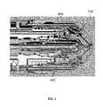
- FIG. 2shows an exemplary communication network 200 of the present invention.
- the communication network 200includes one or more signal devices 202 , each assigned to a consumable of a thermal processing torch, such as the plasma arc torch 100 of FIG. 1 .
- Exemplary consumablesinclude the electrode 105 , the nozzle 110 , the retaining cap 115 , the swirl ring 120 , and the shield 125 .
- a signal device 202is an electrically writable device configured to transmit information about a consumable in the form of one or more signals.
- the signal device 202can be a radio-frequency identification (RFID) tag or card, bar code label or tag, integrated circuit (IC) plate, or the like.
- RFIDradio-frequency identification
- a signal device 202is a detector (e.g., a sensor) for detecting a physical characteristic of the consumable and transmitting the detected information in the form of one or more signals.
- the communication network 200also includes at least one receiver 204 for i) receiving signals transmitted by the signal devices 202 , ii) extracting data conveyed by the signals, and iii) providing the extracted data to a processor 206 for analysis and further action.
- the processor 206can be a digital signal processor (DSP), microprocessor, microcontroller, computer, computer numeric controller (CNC) machine tool, programmable logic controller (PLC), application-specific integrated circuit (ASIC), or the like.
- DSPdigital signal processor
- CNCcomputer numeric controller
- PLCprogrammable logic controller
- ASICapplication-specific integrated circuit
- each signal device 202is encoded with information pertaining to the consumable to which the signal device 202 is assigned.
- the encoded informationcan be generic or fixed information such as the consumable's name, trademark, manufacturer, serial number, and/or type.
- the encoded informationcan include a model number to generally indicate that the consumable is a nozzle.
- the encoded informationis unique to the consumable, such as metal composition of the consumable, weight of the consumable, date, time and/or location at which the consumable was manufactured, personnel responsible for the consumable, and the like.
- the encoded informationcan provide a serial number, which is unique to each torch component manufactured, to distinguish, for example, nozzle Type A, Serial #1 from nozzle Type A, Serial #2.
- informationis encoded to a signal device 202 at the time of manufacture of the corresponding consumable.
- Informationcan also be encoded to a signal device 202 during the lifetime of the consumable, such as after each consumable use.
- Such informationcan include the date, time and location of consumable use, any abnormalities detected during use, and/or consumable conditions after use so that a log can be created to predict a failure event or end-of-life event associated with the consumable.
- Information encoded to a signal device 202can also specify operating parameters. For example, for a signal device 202 associated with the shield 125 , data encoded to the signal device 202 can indicate the type of shield gas and/or the appropriate gas flow rate for the shield 125 . In some embodiments, encoded data of a signal device 202 provides information about other related torch components. For example, encoded data can identify other torch components that are compatible with the assigned consumable, assisting with installation of the entire consumable set in a torch to achieve certain performance metrics.
- a signal device 202includes information about the corresponding consumable independent of a detectable physical characteristic of the consumable.
- detectable physical characteristics of the consumableinclude magnetic properties, surface reflectivity, density, acoustic properties and other tactile features of the consumable measured by a detector installed in the torch. Therefore, examples of consumable data independent of a detectable physical characteristic of the consumable can include consumable name, type, manufacturer, manufacturing date, manufacturing location, serial number, or other non-tactile features of a consumable.
- the signal device 202stores pre-collected information of the consumable, including physical characteristics, before it is installed into the torch, but the signal device 202 is not configured to actively measure or detect the physical characteristics. However, the signal device 202 can store physical characteristics about the consumable measured or detected by another device, such as by a sensor. Generally, the signal device 202 is used mainly for data storage purposes.
- the signal device 202is located inside or on the torch 100 .
- the signal device 202can be attached to a surface of a consumable that is ultimately installed inside of the torch tip 104 .
- the signal device 202can also be attached to a component inside of the torch 100 other than the assigned consumable.
- the signal device 202can be affixed to a surface of the retaining cap 115 .
- the signal device 202is coupled to an external source that is not physically associated with the torch 100 .
- the signal device 202can be attached to a package used to store the consumable and is remote from the consumable once it is installed in the torch 100 .
- the surface to which the signal device 202 is attachedcan be selected to reduce or otherwise minimize heat exposure during operation of the torch 100 .
- the signal device 202can be located near a cooling mechanism, away from the plasma arc, and/or in an o-ring channel of the torch 100 to reduce or minimize heat exposure.
- the signal device 202can be coated with a heat protective material to prevent the device from overheating during torch operation.
- the signal device 202can be situated, such as being shielded by another torch component, to minimize exposure to thermal energy, radiation, damaging gases (e.g., ozone), and/or high-frequency energy.
- a signal device 202is designed to be durable, i.e., functional during and after one or more torch ignitions. In some embodiments, a signal device 202 is disposable after each torch use or after several uses. In some embodiments, a signal device 202 is writable once, for example, to encode information about a consumable when the consumable is first manufactured. In some embodiments, a signal device 202 is writable multiple times, such as throughout the lifespan of the corresponding consumable.
- the signal device 202can wirelessly transmit its stored information to the receiver 204 in the form of one or more signals.
- the receiver 204is adapted to process these signals to extract pertinent data about the consumable and forward the data to the processor 206 for analysis.
- the receiver 204is located in or on the plasma arc torch 100 .
- the receiver 204can be located in the torch body 102 .
- the receiver 204is at a location external to the torch 100 , such as attached to a power supply module, a gas console, the processor 206 , etc.
- the signal devices 202is an RFID tag and the receiver 204 is a reader used to interrogate the RFID tag.
- the RFID tagincludes a microchip for storing information and an antenna for receiving and transmitting RF signals.
- the readercan include 1) an antenna for transmitting RF signals to the RFID tag to interrogate the tag and 2) components for decoding a response transmitted by the RFID tag before forwarding the response to the processor 206 .
- the RFID tagcan be either active or passive.
- An active RFID tagincludes a battery to produce a stronger electromagnetic return signal to the reader, thereby increasing the possible transmission distance between the RFID tag and the reader.
- the distance between an RFID tag and a readercan be from less than one inch to 100 feet or more, depending on the power output, the radio frequency used and the type of material through which the RF signals need to travel. In one example, the distance between an RFID tag and an antenna of a corresponding reader can be about 2-4 cm.
- a reader antenna and remaining reader componentsdo not need be in the same packaging.
- the reader antennacan be located on or inside of the torch body 102 while the remaining reader components are external to the torch 100 .
- Using an RFID tagis advantageous because it does not require direct contact (e.g., via wires) or direct line of sight (e.g., via optical signals) with the reader and is well suited for use in harsh environments.
- a signal device 202is a detector (e.g., a sensor) for detecting at least one physical marker of the consumable for uniquely identifying the consumable by its type or individually.
- the physical markercan be a physical alteration of the consumable, for example.
- identification of a consumableis achieved by altering the geometry of the consumable such that, when it is installed in the torch 100 , it affects the wall of an adjacent coolant passageway 402 , which in turn alters the rate of a coolant flowing therethrough. Specifically, the altered section of the coolant passageway 402 can restrict the rate of the coolant flow.
- a signal device 202can be used to measure the pressure change as a function of the coolant flow rate.
- the measured coolant pressure changeserves as an identification of the consumable.
- an auxiliary vent line 404that is connected to a valve and a flow meter is attached to the nozzle 110 to identify the nozzle 110 .
- the valveis opened prior to plasma arc ignition and the auxiliary vent line flow rate is measured by a signal device 202 as a function of plasma pressure during a purge cycle. Therefore, the measured flow rate serves as an identification of the nozzle 110 .
- one or more uniquely sized metering holescan be drilled into the outer retain cap to identify the cap once it is installed in the torch 100 .
- each metering holeis configured to uniquely affect the off-valve pressure and/or the flow rate of the shield gas. Therefore, these measurements, taken by a signal device 202 in a pre-flow routine prior to pilot arc ignition, serve to identify the outer retaining cap.
- the shield 125can be identified by measuring the consumable's length relative to a reference torch datum.
- a torch height controlleris used to determine the height at which a known torch fires and begins to cut a workpiece. This height can serve as the reference torch datum. Then, after installing an unidentified consumable into the torch, the height relative to the reference datum is determined. Therefore, simple calculations involving the two heights can be used to determine the relative length of the unidentified consumable.
- the relative consumable lengthcan be used to identify the consumable by, for example, referencing a looking-up table that correlates relative consumable lengths to consumable parts.
- a signal device 202is a barcode that provides optical machine-representation of data about the corresponding consumable.
- a barcodecan be read by the receiver 204 in the form of a barcode reader.
- a signal device 202can convey data about a consumable in the form of any machine readable signals, including radio signals, optical or other light-based signals (e.g., infrared signals or ultraviolet signals), magnetic signals, pneumatic signals, or hydraulic signals.
- a single signal device 202is assigned to each consumable of a torch to transmit pertinent information about the corresponding consumable.
- two or more signal devices 202are assigned to the same consumable to transmit different information about that consumable.
- one signal device 202can transmit information unique to the consumable type, such as the model number and operating parameters for the consumable type, while another signal device 202 can transmit information unique to the consumable itself, such as weight and usage history of the consumable.
- the signal devices 202 in the communication network 200employ different modes of data transmission. For example, while one signal device 202 transmits data as RF signals, another signal device 202 transmits data as optical signals.
- the network 200includes multiple receivers 204 .
- Each receiver 204is configured (e.g., tuned) to read signals from one or more of the signal devices 202 and transmit the extracted data to the processor 206 .
- a single receiver 204is used to read signals from all signal devices 202 in the communication network 200 .
- the processor 206thus can simultaneously process data associated with multiple consumables.
- FIG. 4is an exemplary thermal processing system 300 using the communication network of FIG. 2 to control the operation of a thermal processing torch, such as the plasma arc torch 100 of FIG. 1 .
- the plasma arc torch 100can include one or more consumables including the nozzle 110 , the electrode 105 , the shield 125 , the inner retaining cap 115 and an outer retaining cap 302 .
- At least one signal device 202is assigned to at least one of the consumables for transmitting information about the corresponding consumable to the processor 206 via the receiver 204 .
- the system 300also includes a power supply 304 for providing the electrical current necessary to generate plasma arc in the torch 100 .
- Data collected from the signal devices 202 about the respective consumablescan be used by the processor 206 to control and optimize the operation of at least one of the plasma power supply 304 , the motors and drivers 306 , the gas console 308 , the height controller 310 and the nesting software 312 .
- the processor 206can be located inside or outside of the plasma arc torch 100 . In some embodiments, the processor 206 is housed in the power supply 304 . In some embodiments, each of the plasma power supply 304 , the motors and drivers 306 , the gas console 308 , the height controller 310 and the nesting software 312 houses at least one processor for processing data from the signal devices 202 to control the functions of the respective module 304 , 306 , 308 or 310 .
- the processor 206can regulate many plasma system functions simultaneously or near simultaneously and in real-time or near real-time. These system functions include, but not limited to, start sequence, CNC interface functions, gas and operating parameters, and shut off sequences.
- the processor 206uses consumable information to automatically set various parameters of the system 300 .
- the processor 206uses consumable information to verify whether certain preset parameters of the system 300 are compatible with the consumables inside of the torch 100 .
- the processor 206can control and verify one or more of the following system components: i) settings of the power supply 304 for regulating power to the torch 100 , ii) settings of the nesting software 312 for processing a workpiece, iii) settings of the gas console 308 for controlling shield and/or plasma gases supplied to the torch 100 , iv) settings of the height controller 310 for adjusting the height between the torch 100 and the workpiece, and v) settings of various motors and drivers 306 .
- the processor 206interacts with the nesting software 312 to automatically select a cutting program that sets parameters for processing a workpiece, such as the cutting speed, direction, paths, nesting sequences, etc.
- the cutting programcan also define the gas types, gas pressure and/or flow settings and height control settings for the torch in view of the collected consumable data.
- an operatorneeds to manually configure the nesting software 312 to create the cutting program for the torch by supplying information to the software including the type and thickness of the workpiece material being processed, the type of gas being used, and the current rating of the consumable set.
- the operatorneeds to manually input into the processor 206 the current rating of the consumable set.
- the processor 206can electronically collect such information from the one or more signal devices 202 and automatically determine the appropriate current setting without user input.
- the processor 206selects a suitable cutting program from the nesting software 312 by taking into consideration of consumable data from the signal devices 202 and user-input operating parameters, including the characteristics of the workpeice being cut and the desired cut shape. For example, an operator can first send a generic program file to the nesting software 312 .
- the generic program filespecifies, for each workpiece thickness, variable cut speeds, gas flows, kerf compensations, torch heights, etc. that change with different consumable parts.
- the processor 206interacts with the generic program file to configure a cutting program for the torch.
- the processor 206uses consumable data collected from the signal devices 202 to verify whether correct consumables are installed into the torch that are appropriate for the program.
- the processor 206can instruct the nesting software 312 to automatically set or correct parameters of the program to enhance compatibility with the consumables loaded into the torch. For example, a consumable requiring 400 A current has larger kerfs and lead-ins in comparison to a consumable requiring 130 A current. Accordingly, the nesting software 312 can select fewer parts to fit on a nest of the program if the 400 A consumable is loaded into a torch.
- the processor 206can manipulate a gas console 308 to control flow of plasma and shield gases to the torch 100 by verifying and adjusting the gas console settings.
- the gas console 308houses solenoid valves, flow meters, pressure gauges, and switches used for plasma and shield gas flow control. For example, the flow meters are used to set the pre-flow rates and cut flow rates for the plasma and shield gases.
- the gas console 308can also have a multi-inlet gas supply area where the plasma and shield gases are connected. A toggle switch can be used to select the desired gases.
- the plasma and shield gasesare monitored by gas pressure gauges.
- a signal device 202 associated with the shield 125 of the plasma arc torch 100can store information about the type and composition of one or more shield gases suitable for use with the shield 125 , along with the optimal flow rate setting of the shield gases. Based on this data, the processor 206 can interact with the gas console 308 to provide the plasma arc torch 100 with the appropriate shield gas at the optimal flow rate.
- the processor 206manipulates the torch height controller 310 , which sets the height of the torch 100 relative to the workpiece.
- the torch height controller 310can include a control module to control an arc voltage during cutting by adjusting the standoff (i.e., the distance between the torch 100 and the work piece) to maintain a predetermined arc voltage value.
- the torch height controller 310can also include an external control module to control the standoff.
- the torch height controller 310can further include a lifter, which is controlled by the control module through a motor or driver 306 , to slide the torch 100 in a vertical direction relative to the workpiece to maintain the desired voltage during cutting.
- the torch height controller 310can automatically determine the height to position the torch relative to the top of a workpiece. Therefore, the torch height controller 310 does not need to perform a height sense in order to set an appropriate pierce height and cut height before beginning arc voltage control.
- the processor 206is configured to prevent the thermal processing system 300 from commencing an operation on the workpiece if it determines that the consumables installed in the torch 100 are mismatched with each other, not compatible with the thermal processing system 300 or inconsistent with other pre-selected operating parameters input by an operator. If such a determination is made, the processor 206 can trigger an audio or visual alert indicating to the operator that one or more of the connected consumables are unsupported and that the consumables should be replaced or operator inputs should be revised. Additionally, the processor 206 can prevent initiation of an operation if an alert is triggered.
- the processor 206can stop torch operation if the current setting of the shield 125 , which is conveyed to the processor 206 by a signal device 202 assigned to the shield 125 , is different from the current setting of the nozzle 110 , which is conveyed to the processor 206 by a different or the same signal device 202 corresponding to the nozzle 110 .
- the processor 206is configured to prevent the thermal processing system 300 from operating if it determines that at least one of the consumables installed in the torch 100 is not manufactured or otherwise supported by an accepted manufacturer. For example, the processor 206 can stop torch operation if it does not recognize the manufacturer identification, serial number and/or parts number conveyed by a signal device of a consumable. Hence, the thermal processing system 300 can be used to detect and prevent the use of inferior or counterfeit consumables.
- the processor 206recommends one or more remedial actions to the operator to address alarm situations. For example, the processor 206 can suggest one or more consumables to install in the torch 100 to avoid potential mismatch with other components of thermal processing system 300 . The processor 206 can suggest suitable types of workpiece for processing based on the ratings of the installed consumable set. The processor 206 can recommend a cutting sequence that reconciles the settings of the installed consumables with settings provided by the operator.
- the signal devices 204can store information about torch components other than consumables.
- the signal devices 204can store information about the torch body 102 or about one or more leads. Therefore, as one in the art will fully appreciate, the exemplary communication network 200 of FIG. 2 and the configuration of FIG. 3 can be easily adapted to store information about any torch component.
- the invention described hereinis not only applicable to plasma cutting devices, but also welding-type systems and other thermal processing systems.
- the invention described hereinis configured to operate with a variety of cutting technologies, including, but not limited to, plasma arc, laser, oxy fuel, and/or water-jet technologies.
- the signal devices 202can be coupled to one or more consumables configured to operate with one or more of the cutting technologies.
- the processor 206using information transmitted by the signal devices 202 , can determine whether the consumables installed in a torch are compatible with the specific cutting technology. In some embodiments, based on the selected cutting technology and the consumable information, the processor 206 can set or adjust operating parameters accordingly, such as the height of the cutting head above the workpiece, which can vary depending on the cutting technology and the consumables.
- abrasive jetis a type of water jet, which can include abrasive materials within the fluid jet for cutting harder materials.
- the signal devices 202are attached to consumables of a water-jet system, such as to a water-jet nozzle, an abrasive-jet nozzle, a mixing tube used to mix abrasive particles with fluid, and/or one or more valves and filters.
- a signal device 202 associated with an abrasive jet nozzlecan identify, for example, the types of abrasives suitable for use with the nozzle, the amount of pressure in the pressurized fluid that can be fed to the nozzle, and can also indicate other consumables that are suitable for use with a particular nozzle. Identification of particular consumable set combinations for a given water-jet system can also be performed, to verify compatibility with a given system or to limit operating conditions and parameters, such as maximum pressure or flow settings, or abrasive types or amounts.
Landscapes
- Engineering & Computer Science (AREA)
- Physics & Mathematics (AREA)
- Plasma & Fusion (AREA)
- Spectroscopy & Molecular Physics (AREA)
- Mechanical Engineering (AREA)
- Arc Welding In General (AREA)
- Plasma Technology (AREA)
- Coating By Spraying Or Casting (AREA)
- Control Of Combustion (AREA)
- Control Of Positive-Displacement Air Blowers (AREA)
- Arc Welding Control (AREA)
Abstract
Description
Claims (10)
Priority Applications (37)
| Application Number | Priority Date | Filing Date | Title |
|---|---|---|---|
| US13/439,259US10455682B2 (en) | 2012-04-04 | 2012-04-04 | Optimization and control of material processing using a thermal processing torch |
| US13/560,059US20130263420A1 (en) | 2012-04-04 | 2012-07-27 | Optimization and Control of Material Processing Using a Thermal Processing Torch |
| AU2013243978AAU2013243978B2 (en) | 2012-04-04 | 2013-01-14 | Optimization and control of material processing using a thermal processing torch |
| TR2019/08419TTR201908419T4 (en) | 2012-04-04 | 2013-01-14 | Optimization and control of material processing using a thermal processing blower. |
| RU2014144287ARU2634709C2 (en) | 2012-04-04 | 2013-01-14 | Optimisation and control of material processing, using heat treatment burner |
| EP13702677.9AEP2835040B1 (en) | 2012-04-04 | 2013-01-14 | Optimization and control of material processing using a thermal processing torch |
| CN201380018721.9ACN104322152B (en) | 2012-04-04 | 2013-01-14 | Use the optimization and control of the material process of heat treatment torch |
| JP2015504547AJP6251722B2 (en) | 2012-04-04 | 2013-01-14 | How to convey information about consumable parts of a heating torch |
| KR1020147030487AKR102036216B1 (en) | 2012-04-04 | 2013-01-14 | Optimization and control of material processing using a thermal processing torch |
| BR112014024906-7ABR112014024906B1 (en) | 2012-04-04 | 2013-01-14 | optimization and control of the processing material using a thermal processing torch |
| PCT/US2013/021364WO2013151602A2 (en) | 2012-04-04 | 2013-01-14 | Optimization and control of material processing using a thermal processing torch |
| US13/838,919US10486260B2 (en) | 2012-04-04 | 2013-03-15 | Systems, methods, and devices for transmitting information to thermal processing systems |
| JP2015504637AJP6251723B2 (en) | 2012-04-04 | 2013-03-29 | Torch for cutting or welding process |
| BR112014024907ABR112014024907A2 (en) | 2012-04-04 | 2013-03-29 | systems, methods and devices for transmitting information to thermal processing systems |
| CN201380029346.8ACN104472021B (en) | 2012-04-04 | 2013-03-29 | System, method and apparatus for heat treated system transmitting information |
| EP18207623.2AEP3518629B1 (en) | 2012-04-04 | 2013-03-29 | Systems, methods, and devices for transmitting information to thermal processing systems |
| RU2014144288ARU2649906C2 (en) | 2012-04-04 | 2013-03-29 | Systems, methods and devices for transmitting information to thermal processing systems |
| PCT/US2013/034572WO2013151886A2 (en) | 2012-04-04 | 2013-03-29 | Systems, methods, and devices for transmitting information to thermal processing systems |
| KR1020147030465AKR101897319B1 (en) | 2012-04-04 | 2013-03-29 | Systems, methods, and devices for transmitting information to thermal processing systems |
| EP13716665.8AEP2835041B1 (en) | 2012-04-04 | 2013-03-29 | Systems, methods, and devices for transmitting information to thermal processing systems |
| EP24178117.8AEP4397431A3 (en) | 2012-04-04 | 2013-03-29 | Systems, methods, and devices for transmitting information to thermal processing systems |
| AU2013243710AAU2013243710B2 (en) | 2012-04-04 | 2013-03-29 | Systems, methods, and devices for transmitting information to thermal processing systems |
| US14/075,692US20140061170A1 (en) | 2012-04-04 | 2013-11-08 | Identifying Thermal Processing Torch Components |
| US14/079,163US20140069895A1 (en) | 2012-04-04 | 2013-11-13 | Automated cartridge detection for a plasma arc cutting system |
| US14/135,714US9144882B2 (en) | 2012-04-04 | 2013-12-20 | Identifying liquid jet cutting system components |
| US14/486,569US9782852B2 (en) | 2010-07-16 | 2014-09-15 | Plasma torch with LCD display with settings adjustment and fault diagnosis |
| US14/589,270US9395715B2 (en) | 2012-04-04 | 2015-01-05 | Identifying components in a material processing system |
| US14/807,589US9672460B2 (en) | 2012-04-04 | 2015-07-23 | Configuring signal devices in thermal processing systems |
| US14/807,679US20150332071A1 (en) | 2012-04-04 | 2015-07-23 | Configuring Signal Devices in Thermal Processing Systems |
| US15/056,437US9737954B2 (en) | 2012-04-04 | 2016-02-29 | Automatically sensing consumable components in thermal processing systems |
| JP2017180029AJP6397102B2 (en) | 2012-04-04 | 2017-09-20 | Replaceable consumable parts for heating torches, torches and related methods |
| US15/863,402US10346647B2 (en) | 2012-04-04 | 2018-01-05 | Configuring signal devices in thermal processing systems |
| US16/425,197US10713448B2 (en) | 2012-04-04 | 2019-05-29 | Configuring signal devices in thermal processing systems |
| US16/598,654US11331743B2 (en) | 2012-04-04 | 2019-10-10 | Systems, methods, and devices for transmitting information to thermal processing systems |
| US16/892,736US11087100B2 (en) | 2012-04-04 | 2020-06-04 | Configuring signal devices in thermal processing systems |
| US17/382,992US11783138B2 (en) | 2012-04-04 | 2021-07-22 | Configuring signal devices in thermal processing systems |
| US18/462,283US12217118B2 (en) | 2012-04-04 | 2023-09-06 | Configuring signal devices in thermal processing systems |
Applications Claiming Priority (1)
| Application Number | Priority Date | Filing Date | Title |
|---|---|---|---|
| US13/439,259US10455682B2 (en) | 2012-04-04 | 2012-04-04 | Optimization and control of material processing using a thermal processing torch |
Related Parent Applications (2)
| Application Number | Title | Priority Date | Filing Date |
|---|---|---|---|
| US13/560,059Continuation-In-PartUS20130263420A1 (en) | 2010-07-16 | 2012-07-27 | Optimization and Control of Material Processing Using a Thermal Processing Torch |
| US13/949,364Continuation-In-PartUS9481050B2 (en) | 2010-07-16 | 2013-07-24 | Plasma arc cutting system and persona selection process |
Related Child Applications (2)
| Application Number | Title | Priority Date | Filing Date |
|---|---|---|---|
| US13/560,059Continuation-In-PartUS20130263420A1 (en) | 2010-07-16 | 2012-07-27 | Optimization and Control of Material Processing Using a Thermal Processing Torch |
| US14/075,692Continuation-In-PartUS20140061170A1 (en) | 2010-07-16 | 2013-11-08 | Identifying Thermal Processing Torch Components |
Publications (2)
| Publication Number | Publication Date |
|---|---|
| US20130264320A1 US20130264320A1 (en) | 2013-10-10 |
| US10455682B2true US10455682B2 (en) | 2019-10-22 |
Family
ID=47664418
Family Applications (1)
| Application Number | Title | Priority Date | Filing Date |
|---|---|---|---|
| US13/439,259Active2037-08-13US10455682B2 (en) | 2010-07-16 | 2012-04-04 | Optimization and control of material processing using a thermal processing torch |
Country Status (10)
| Country | Link |
|---|---|
| US (1) | US10455682B2 (en) |
| EP (1) | EP2835040B1 (en) |
| JP (1) | JP6251722B2 (en) |
| KR (1) | KR102036216B1 (en) |
| CN (1) | CN104322152B (en) |
| AU (1) | AU2013243978B2 (en) |
| BR (1) | BR112014024906B1 (en) |
| RU (1) | RU2634709C2 (en) |
| TR (1) | TR201908419T4 (en) |
| WO (1) | WO2013151602A2 (en) |
Cited By (5)
| Publication number | Priority date | Publication date | Assignee | Title |
|---|---|---|---|---|
| US20240179826A1 (en)* | 2021-04-01 | 2024-05-30 | Edwards Limited | Plasma torch device component monitoring |
| US12217118B2 (en) | 2012-04-04 | 2025-02-04 | Hypertherm, Inc. | Configuring signal devices in thermal processing systems |
| US12275082B2 (en) | 2013-11-13 | 2025-04-15 | Hypertherm, Inc. | Consumable cartridge for a plasma arc cutting system |
| US12280441B2 (en) | 2017-02-09 | 2025-04-22 | Hypertherm, Inc. | Swirl ring and contact element for a plasma arc torch cartridge |
| US12423537B2 (en) | 2021-09-10 | 2025-09-23 | Esab Ab | Marked consumable reading |
Families Citing this family (28)
| Publication number | Priority date | Publication date | Assignee | Title |
|---|---|---|---|---|
| US8431862B2 (en) | 2005-08-25 | 2013-04-30 | Lincoln Global, Inc. | Torch for electric arc welding system |
| US10144080B2 (en) | 2005-08-25 | 2018-12-04 | Lincoln Global, Inc. | Torch for electric arc welding or plasma cutting system |
| US10455682B2 (en) | 2012-04-04 | 2019-10-22 | Hypertherm, Inc. | Optimization and control of material processing using a thermal processing torch |
| US10486260B2 (en)* | 2012-04-04 | 2019-11-26 | Hypertherm, Inc. | Systems, methods, and devices for transmitting information to thermal processing systems |
| US9481050B2 (en) | 2013-07-24 | 2016-11-01 | Hypertherm, Inc. | Plasma arc cutting system and persona selection process |
| US9782852B2 (en) | 2010-07-16 | 2017-10-10 | Hypertherm, Inc. | Plasma torch with LCD display with settings adjustment and fault diagnosis |
| US9672460B2 (en) | 2012-04-04 | 2017-06-06 | Hypertherm, Inc. | Configuring signal devices in thermal processing systems |
| US9144882B2 (en) | 2012-04-04 | 2015-09-29 | Hypertherm, Inc. | Identifying liquid jet cutting system components |
| US9395715B2 (en) | 2012-04-04 | 2016-07-19 | Hypertherm, Inc. | Identifying components in a material processing system |
| US9737954B2 (en) | 2012-04-04 | 2017-08-22 | Hypertherm, Inc. | Automatically sensing consumable components in thermal processing systems |
| US20150332071A1 (en)* | 2012-04-04 | 2015-11-19 | Hypertherm, Inc. | Configuring Signal Devices in Thermal Processing Systems |
| US9643273B2 (en) | 2013-10-14 | 2017-05-09 | Hypertherm, Inc. | Systems and methods for configuring a cutting or welding delivery device |
| RU2666779C1 (en)* | 2013-11-13 | 2018-09-12 | Гипертерм, Инк. | Automated cartridge detection for plasma arc cutting system |
| WO2015128719A1 (en)* | 2014-02-26 | 2015-09-03 | Lincoln Global, Inc. | Torch for electric arc welding or plasma cutting system |
| WO2015134966A1 (en) | 2014-03-07 | 2015-09-11 | Hypertherm, Inc. | Liquid pressurization pump and systems with data storage |
| US10786924B2 (en) | 2014-03-07 | 2020-09-29 | Hypertherm, Inc. | Waterjet cutting head temperature sensor |
| US20150269603A1 (en) | 2014-03-19 | 2015-09-24 | Hypertherm, Inc. | Methods for Developing Customer Loyalty Programs and Related Systems and Devices |
| US10137522B2 (en) | 2015-07-02 | 2018-11-27 | Lincoln Global, Inc. | Adaptive plasma cutting system and method |
| BR112018002280B1 (en)* | 2015-08-04 | 2022-09-13 | Hypertherm, Inc | LIQUID-COOLED PLASMA ARC TORCH CARTRIDGE |
| US10449615B2 (en)* | 2016-10-31 | 2019-10-22 | Illinois Tool Works Inc. | Hybrid welding modules |
| US10674593B2 (en)* | 2017-09-15 | 2020-06-02 | Lincoln Global, Inc. | Plasma processing system with consumable identification |
| US11267069B2 (en)* | 2018-04-06 | 2022-03-08 | The Esab Group Inc. | Recognition of components for welding and cutting torches |
| US10625359B2 (en) | 2018-04-06 | 2020-04-21 | The Esab Group Inc. | Automatic identification of components for welding and cutting torches |
| IT201800011036A1 (en)* | 2018-12-12 | 2020-06-12 | Bicarjet S R L | SANDBLASTING MACHINE WITH ABRASIVE MATERIAL LOADING CONTROL SYSTEM |
| US11664971B2 (en) | 2019-11-13 | 2023-05-30 | The Esab Group Inc. | Encrypted communication between components of welding and cutting systems |
| JP7474610B2 (en)* | 2020-03-10 | 2024-04-25 | コマツ産機株式会社 | Plasma cutting machine and its control method |
| US11839015B2 (en) | 2021-02-04 | 2023-12-05 | The Esab Group Inc. | Consumables for processing torches |
| US20240096637A1 (en)* | 2022-09-15 | 2024-03-21 | Samsung Electronics Co., Ltd. | Substrate processing apparatus and substrate processing method using the same |
Citations (178)
| Publication number | Priority date | Publication date | Assignee | Title |
|---|---|---|---|---|
| US2985050A (en) | 1958-10-13 | 1961-05-23 | North American Aviation Inc | Liquid cutting of hard materials |
| US3010012A (en) | 1959-12-24 | 1961-11-21 | Air Reduction | Arc welding |
| US3018360A (en) | 1960-04-25 | 1962-01-23 | Air Reduction | Arc welding torch |
| US3518401A (en) | 1967-10-04 | 1970-06-30 | Air Reduction | Electric arc pulsing |
| US3602683A (en) | 1969-02-03 | 1971-08-31 | Sumitomo Heavy Industries | Automatic control mechanism for plasma welder |
| US4125754A (en) | 1976-01-15 | 1978-11-14 | Rene Wasserman | Installation for surfacing using plasma-arc welding |
| US4497029A (en) | 1981-04-15 | 1985-01-29 | Mitsubishi Denki Kabushiki Kaisha | Numerical control device |
| US4519835A (en) | 1981-07-30 | 1985-05-28 | Hydro-Quebec | Transferred-arc plasma reactor for chemical and metallurgical applications |
| JPS6163368A (en) | 1984-09-03 | 1986-04-01 | Takashi Murata | Automatic setting method of welding condition for covered electrode |
| US4588880A (en) | 1982-09-16 | 1986-05-13 | Robert Bosch Gmbh | Non-contacting code recognition system for code carriers on production line workpieces |
| US4733052A (en) | 1985-02-15 | 1988-03-22 | Esab Aktiebolag | Contact tip welding electrode |
| US4742470A (en)* | 1985-12-30 | 1988-05-03 | Gte Valeron Corporation | Tool identification system |
| US4929811A (en) | 1988-12-05 | 1990-05-29 | The Lincoln Electric Company | Plasma arc torch interlock with disabling control arrangement system |
| US5018670A (en) | 1990-01-10 | 1991-05-28 | Possis Corporation | Cutting head for water jet cutting machine |
| US5050106A (en) | 1987-10-07 | 1991-09-17 | Omron Tateisi Electronics Co. | Article recognizing system |
| US5086655A (en) | 1985-10-15 | 1992-02-11 | Avl Gesellschaft Fuer Verbrennungskraftmaschinen Und Messtechnik Mbh | Orifice measuring device |
| US5099226A (en) | 1991-01-18 | 1992-03-24 | Interamerican Industrial Company | Intelligent security system |
| EP0508482A2 (en) | 1991-04-12 | 1992-10-14 | The Lincoln Electric Company | Plasma torch with identification circuit |
| JPH05154732A (en) | 1991-11-30 | 1993-06-22 | Nippei Toyama Mechatronics:Kk | Machining device with tool exchanging system |
| US5248867A (en) | 1990-11-30 | 1993-09-28 | Mitsubishi Denki K.K. | Electric spark machine |
| US5309683A (en) | 1992-01-28 | 1994-05-10 | Sandroid Systems, Inc. | Recovery system |
| US5381487A (en) | 1989-01-25 | 1995-01-10 | Shamos; Morris H. | Patient identification system |
| US5388965A (en) | 1990-10-10 | 1995-02-14 | Friedrich Wilhelm Schwing Gmbh | Sludge pump with monitoring system |
| US5390964A (en) | 1992-10-01 | 1995-02-21 | Gray, Jr.; Lawrence C. | Labeled pipe fitting and method |
| US5400389A (en) | 1992-05-19 | 1995-03-21 | Fujitsu Limited | System for rewriting information in rewritable memory provided in portable remote terminal and portable remote terminal applicable to the system |
| US5440477A (en) | 1991-05-20 | 1995-08-08 | Creative Pathways, Inc. | Modular bottle-mounted gas management system |
| US5500512A (en) | 1994-12-16 | 1996-03-19 | General Electric Company | Welding wire verification control system |
| US5556562A (en)* | 1994-12-12 | 1996-09-17 | J. W. Harris Co., Inc. | Welding assembly |
| US5653264A (en) | 1995-10-13 | 1997-08-05 | Atkinson; Louis D. | Fluid orifice device having encoded orifice size indicia |
| US5717187A (en) | 1994-03-25 | 1998-02-10 | Commonwealth Scientific And Industrial Research Organisation | Plasma torch condition monitoring |
| US5860849A (en) | 1997-03-25 | 1999-01-19 | Huffman Corp | Liquid abrasive jet focusing tube for making non-perpendicular cuts |
| JPH11285831A (en) | 1998-04-07 | 1999-10-19 | Koike Sanso Kogyo Co Ltd | Cutting equipment |
| US5994663A (en) | 1996-10-08 | 1999-11-30 | Hypertherm, Inc. | Plasma arc torch and method using blow forward contact starting system |
| US6047579A (en) | 1998-04-17 | 2000-04-11 | The Minster Machine Company | RF tag attached to die assembly for use in press machine |
| US6130407A (en) | 1998-07-29 | 2000-10-10 | Tregaskiss, Ltd. | Arc welding torch |
| CA2439213A1 (en) | 1999-06-21 | 2000-12-21 | Lincoln Global, Inc. | Coded and electronically tagged welding wire |
| EP1065620A2 (en) | 1999-06-21 | 2001-01-03 | Lincoln Global, Inc. | Coded and electronically tagged welding wire |
| US6201207B1 (en) | 2000-01-13 | 2001-03-13 | Koike Sanso Kogyo Co., Ltd. | Torch angle setting apparatus |
| US6248975B1 (en) | 1997-05-16 | 2001-06-19 | Illinois Tool Works Inc. | Welding machine with automatic parameter setting |
| US6259059B1 (en) | 1999-12-21 | 2001-07-10 | Lincoln Global, Inc. | Arc welder and torch for same |
| EP1117279A1 (en)* | 2000-01-17 | 2001-07-18 | L'air Liquide, Societe Anonyme Pour L'etude Et L'exploitation Des Procedes Georges Claude | Plasma torch with head, electrode and nozzle identification means |
| US6326583B1 (en) | 2000-03-31 | 2001-12-04 | Innerlogic, Inc. | Gas control system for a plasma arc torch |
| US6409476B2 (en) | 1999-08-06 | 2002-06-25 | Djax Corporation | Pumpjack dynamometer and method |
| US20020117484A1 (en) | 2001-02-27 | 2002-08-29 | Jones Joseph P. | Contact start plasma arc torch and method of initiating a pilot arc |
| US6479793B1 (en) | 1998-05-13 | 2002-11-12 | Fronius Schweissmaschinen Produktion Gmbh & Co. Kg | Method for controlling a welding apparatus and corresponding control device |
| JP2003025176A (en) | 2001-07-11 | 2003-01-29 | Incs Inc | Tool management system |
| US20030025598A1 (en) | 2000-01-10 | 2003-02-06 | Filterwerk Mann & Hummel Gmbh | Method and apparatus for monitoring service-intensive replaceable parts in an assembly |
| JP2003048134A (en) | 2001-08-07 | 2003-02-18 | Incs Inc | Tool managing system |
| EP1288016A1 (en) | 2001-01-11 | 2003-03-05 | Hanex Co. Ltd | Communication device and its installation structure, manufacturing method, and communication method |
| US6539818B1 (en) | 1998-09-14 | 2003-04-01 | The United States Of America As Represented By The Administrator Of The National Aeronautics And Space Administration | Process for testing compaction of a swaged heater for an anode sub-assembly of a hollow cathode assembly |
| US20030148709A1 (en) | 2002-02-05 | 2003-08-07 | The Johns Hopkins University | Porous, lubricated nozzle for abrasive fluid suspension jet |
| US6657162B1 (en) | 1999-05-31 | 2003-12-02 | Alexander Binzel Schweisstechnik Gmbh & Co. Kg | Burner head of an electric arc welding or cutting burner with contact nozzle supported in positive fit |
| US6659098B1 (en) | 1999-11-10 | 2003-12-09 | Disco Corporation | Rotary tool including a cutting blade and cutting apparatus comprising the same |
| US6693252B2 (en) | 2002-04-01 | 2004-02-17 | Illinois Tool Works Inc. | Plasma MIG welding with plasma torch and MIG torch |
| US20040031776A1 (en) | 2002-04-29 | 2004-02-19 | Gevelber Michael Alan | Feedback enhanced plasma spray tool |
| US6707304B2 (en)* | 2000-12-12 | 2004-03-16 | Agie Sa | Devices and methods for detecting a processing electrode of a machine tool |
| US6717096B2 (en) | 2001-02-27 | 2004-04-06 | Thermal Dynamics Corporation | Dual mode plasma arc torch |
| US6729468B1 (en) | 2003-03-28 | 2004-05-04 | Thomas N Dobmeier | Circular saw blade holder |
| US20040106101A1 (en) | 2002-12-02 | 2004-06-03 | Evans Daron G. | System and method for quality control of a shipped neural cell culture on a microelectrode array |
| US6772040B1 (en) | 2000-04-10 | 2004-08-03 | Hypertherm, Inc. | Centralized control architecture for a plasma arc system |
| US6781085B2 (en) | 2002-10-09 | 2004-08-24 | Illinois Tool Works Inc. | Method and apparatus of coordinating operating modes of a plasma cutter and a power supply |
| US20040193307A1 (en) | 2003-03-26 | 2004-09-30 | Mori Seiki Co., Ltd. | Maintenance system for machine tool |
| US20050045599A1 (en) | 2003-09-03 | 2005-03-03 | Matus Tim A. | Method and apparatus of coordinating operational feedback in a plasma cutter |
| EP1516688A1 (en) | 2003-09-18 | 2005-03-23 | Illinois Tool Works Inc. | Welding-type system with controller configured for automatic determination of the type of consumables |
| EP1522371A1 (en) | 2003-10-09 | 2005-04-13 | Illinois Tool Works Inc. | Method and apparatus for localized control of a plasma cutter |
| US20050109738A1 (en) | 2003-11-21 | 2005-05-26 | Hewett Roger W. | Color coding of plasma arc torch parts and part sets |
| US20050145688A1 (en) | 2003-12-29 | 2005-07-07 | Milan Milenkovic | Asset management methods and apparatus |
| US6933462B2 (en) | 2003-02-06 | 2005-08-23 | Komatsu Industries Corporation | Plasma processing apparatus for monitoring and storing lifetime usage data of a plurality of interchangeable parts |
| US6960737B2 (en) | 2003-08-29 | 2005-11-01 | Thermal Dynamics Corporation | Gas flow pre-charge for a plasma arc torch |
| US6980704B2 (en) | 1999-05-25 | 2005-12-27 | Silverbrook Research Pty Ltd | Sensing device for sensing coded marks |
| US20060006154A1 (en) | 2004-05-24 | 2006-01-12 | Tetsuo Koike | Plasma torch life duration detecting device |
| US6995545B2 (en) | 2003-08-18 | 2006-02-07 | Mks Instruments, Inc. | Control system for a sputtering system |
| US20060070986A1 (en) | 2004-09-28 | 2006-04-06 | Ihde Jeffery R | System and method of precise wire feed control in a welder |
| US7030337B2 (en) | 2003-12-19 | 2006-04-18 | Honeywell International, Inc. | Hand-held laser welding wand having removable filler media delivery extension tips |
| US7032814B2 (en)* | 1999-06-21 | 2006-04-25 | Lincoln Global, Inc. | Coded welding consumable |
| US20060163216A1 (en) | 2005-01-27 | 2006-07-27 | Hypertherm, Inc. | Automatic gas control for a plasma arc torch |
| US20060163228A1 (en)* | 2005-01-25 | 2006-07-27 | Lincoln Global, Inc. | Methods and apparatus for tactile communication in an arc processing system |
| US20060163230A1 (en) | 2005-01-26 | 2006-07-27 | Kaufman Charles L | System and method for coordinating wire feeder motor operation |
| US20060201923A1 (en) | 2005-03-11 | 2006-09-14 | Hutchison Richard M | Method and system of determining wire feed speed |
| US7115833B2 (en) | 2004-11-03 | 2006-10-03 | The Esab Group, Inc. | Metering system and method for supplying gas to a torch |
| US20060289406A1 (en)* | 2003-09-17 | 2006-12-28 | Pekka Helenius | Cooled plasma torch and method for cooling the torch |
| US20070012099A1 (en) | 2005-07-04 | 2007-01-18 | Alcatel | Vacuum line and a method of monitoring such a line |
| US20070051711A1 (en)* | 2005-08-25 | 2007-03-08 | Lincoln Global, Inc. | Torch for electric arc welding system |
| US20070080153A1 (en) | 2005-10-07 | 2007-04-12 | Bruce Albrecht | Wireless tracking and inventory monitoring for welding-type devices |
| US20070080152A1 (en) | 2005-10-07 | 2007-04-12 | Bruce Albrecht | Wireless communication system for welding-type devices |
| US20070210034A1 (en) | 2006-02-17 | 2007-09-13 | Hypertherm, Inc. | Electrode for a contact start plasma arc torch and contact start plasma arc torch employing such electrodes |
| US7307533B2 (en)* | 2005-01-31 | 2007-12-11 | Fujitsu Limited | Information reading apparatus, information reading system, and RFID tag |
| US20070294608A1 (en) | 2006-05-18 | 2007-12-20 | Huettinger Elektronik Gmbh + Co. Kg | Plasma process power delivery system and method with event-controlled data storage |
| US20080001752A1 (en) | 2005-04-21 | 2008-01-03 | Skyetek, Inc. | System and method for securing rfid tags |
| US20080011821A1 (en) | 2006-07-10 | 2008-01-17 | Daniel Measurement And Control, Inc. | Method and System of Determining Orifice Plate Parameters |
| US20080023451A1 (en) | 2006-07-27 | 2008-01-31 | Salsich Anthony V | Method and apparatus for automatically controlling gas pressure for a plasma cutter |
| US20080061049A1 (en) | 2006-09-07 | 2008-03-13 | Bruce Albrecht | Wireless system control and inventory monitoring for welding-type devices |
| US20080066596A1 (en) | 2004-05-20 | 2008-03-20 | Komatsu Insustries Corporation | Cutting Machine and Method of Moving Cutting Head |
| US20080083711A1 (en) | 2006-09-13 | 2008-04-10 | Hypertherm, Inc. | High Visibility Plasma Arc Torch |
| US20080093476A1 (en) | 2005-06-27 | 2008-04-24 | Johnson Kaj A | Modular Sprayer |
| US7375302B2 (en) | 2004-11-16 | 2008-05-20 | Hypertherm, Inc. | Plasma arc torch having an electrode with internal passages |
| US20080149608A1 (en) | 2006-12-22 | 2008-06-26 | Bruce Albrecht | System and method for identifying welding consumable wear |
| US20080149686A1 (en) | 2006-12-20 | 2008-06-26 | Lincoln Global, Inc. | Welding Job Sequencer |
| US20080156783A1 (en) | 2006-12-29 | 2008-07-03 | Vanden Heuvel Michael L | Portable multi-wire feeder |
| US7411154B2 (en) | 2005-03-24 | 2008-08-12 | Illinois Tool Works Inc. | Control panel for a welding-type apparatus |
| US20080223952A1 (en) | 2007-03-16 | 2008-09-18 | Sulzer Metco Ag | Device and method for the management of data |
| US20080257874A1 (en) | 2007-04-19 | 2008-10-23 | Illinois Tool Works Inc. | Synchronized multiple drive wire feed welding system and method |
| WO2008144785A1 (en) | 2007-05-25 | 2008-12-04 | Fronius International Gmbh | Welding system and method for transmitting information and for influencing parameters of a welding system |
| US20080308641A1 (en) | 2007-04-10 | 2008-12-18 | Advanced Microelectronic And Automation Technology Ltd. | Smart card with switchable matching antenna |
| US20090008370A1 (en) | 2006-07-27 | 2009-01-08 | Salsich Anthony V | Automatic consumable and torch length detection via pressure decay |
| US20090057286A1 (en)* | 2007-03-19 | 2009-03-05 | Hideki Ihara | Welding device |
| US20090065489A1 (en) | 2005-09-09 | 2009-03-12 | John Duffy | Arc welding |
| US20090107960A1 (en) | 2007-10-30 | 2009-04-30 | Gm Global Technology Operations, Inc. | Welding Stability System and Method |
| US20090152255A1 (en) | 2007-12-18 | 2009-06-18 | Illinois Tool Works Inc. | Retaining head and contact tip for controlling wire contour and contacting point for gmaw torches |
| US20090159575A1 (en) | 2007-12-19 | 2009-06-25 | Illinois Tool Works Inc. | Plasma Cutter Having Microprocessor Control |
| US20090163130A1 (en) | 2007-12-21 | 2009-06-25 | Jurijs Zambergs | Ventilation system ofr wide-bodied aircraft |
| US20090159572A1 (en) | 2007-12-19 | 2009-06-25 | Illinois Tool Works Inc. | Plasma Cutter Having Thermal Model for Component Protection |
| US20090184098A1 (en) | 2006-12-05 | 2009-07-23 | Lincoln Global, Inc. | System for measuring energy using digitally controlled welding power sources |
| US20090212027A1 (en) | 2008-02-21 | 2009-08-27 | Hypertherm, Inc. | Binary Signal Detection |
| US20090222804A1 (en) | 2008-02-29 | 2009-09-03 | Illinois Tool Works, Inc. | Embedded firmware updating system and method |
| US20090219136A1 (en) | 2006-08-03 | 2009-09-03 | Olivier Brunet | Secure Document, In Particular Electronic Passport With Enhanced Security |
| US20090230097A1 (en) | 2008-03-12 | 2009-09-17 | Hypertherm, Inc. | Liquid cooled shield for improved piercing performance |
| US20090240368A1 (en) | 2008-03-24 | 2009-09-24 | Hypertherm, Inc. | Method and Apparatus for Operating an Automated High Temperature Thermal Cutting System |
| JP2009252085A (en) | 2008-04-09 | 2009-10-29 | Nec Fielding Ltd | Maintenance operation support system and its method |
| US20090288532A1 (en) | 2008-05-21 | 2009-11-26 | Flow International Corporation | Mixing tube for a waterjet system |
| US7645960B2 (en) | 2004-06-18 | 2010-01-12 | Lincoln Global, Inc. | Coded welding consumable |
| US7671294B2 (en) | 2006-11-28 | 2010-03-02 | Vladimir Belashchenko | Plasma apparatus and system |
| US7680625B2 (en) | 2005-11-14 | 2010-03-16 | Macsema, Inc. | Systems and methods for monitoring system performance |
| US20100078408A1 (en) | 2008-09-30 | 2010-04-01 | Hypertherm, Inc. | Nozzle with exposed vent passage |
| US20100084381A1 (en) | 2007-01-11 | 2010-04-08 | Sbi Produktion Techn. Alagen Gmbh | Process for the plasma spot welding of surface-treated workpieces and plasma torch |
| US20100155377A1 (en) | 2008-12-22 | 2010-06-24 | Hypertherm, Inc. | Method And Apparatus For Cutting High Quality Internal Features And Contours |
| US7843334B2 (en)* | 2006-03-20 | 2010-11-30 | Kumagai Monto H | Method to promote and distribute multimedia content using radio frequency identification tags |
| WO2010142858A1 (en) | 2009-06-12 | 2010-12-16 | Kemppi Oy | Welding optimisation |
| US20100324868A1 (en) | 2009-06-22 | 2010-12-23 | Russell Mark C | Core Sample Preparation, Analysis, And Virtual Presentation |
| US20110000893A1 (en) | 2009-07-06 | 2011-01-06 | Lincoln Global, Inc. | Synergistic welding and electrode selection and identification method |
| US20110029385A1 (en) | 2009-07-28 | 2011-02-03 | Oohdoo, Inc. | System and method for providing advertising content via mobile device docking station |
| US20110114616A1 (en) | 2009-11-17 | 2011-05-19 | Illinois Tool Works Inc. | Welding system with lockout mechanism |
| US20110163857A1 (en) | 2003-04-09 | 2011-07-07 | Visible Assets, Inc. | Energy Harvesting for Low Frequency Inductive Tagging |
| US20110220630A1 (en) | 2010-03-10 | 2011-09-15 | Illinois Tool Works Inc. | Welding wire feeder with multimotor standard |
| US8035487B2 (en) | 2001-08-08 | 2011-10-11 | Stryker Corporation | Method for assembling, identifying and controlling a powered surgical tool assembly assembled from multiple components |
| US20110294401A1 (en) | 2005-08-04 | 2011-12-01 | Par Systems, Inc. | Method of compensation for a fluid cutting apparatus |
| US8085150B2 (en) | 2007-05-29 | 2011-12-27 | Rcd Technology Inc | Inventory system for RFID tagged objects |
| US20120021676A1 (en) | 2010-06-21 | 2012-01-26 | Omax Corporation | Systems for abrasive jet piercing and associated methods |
| JP2012048287A (en) | 2010-08-24 | 2012-03-08 | Mitsubishi Electric Corp | Component management device, component management system, component management method and component management program |
| US8141240B2 (en) | 1999-08-04 | 2012-03-27 | Super Talent Electronics, Inc. | Manufacturing method for micro-SD flash memory card |
| JP2012079221A (en) | 2010-10-05 | 2012-04-19 | Mitsubishi Heavy Ind Ltd | Component management system |
| US20120138583A1 (en) | 2010-12-03 | 2012-06-07 | Itt Manufacturing Enterprises, Inc. | Plasma arc systems with cutting and marking functions |
| US20120139692A1 (en) | 2010-12-06 | 2012-06-07 | Andreas Neubauer | Use block for a handheld work apparatus |
| US8203095B2 (en)* | 2006-04-20 | 2012-06-19 | Materials & Electrochemical Research Corp. | Method of using a thermal plasma to produce a functionally graded composite surface layer on metals |
| US8242907B2 (en) | 2005-12-09 | 2012-08-14 | Tego, Inc. | Multiple radio frequency network node RFID tag |
| US8263896B2 (en) | 2005-01-03 | 2012-09-11 | Illinois Tool Works Inc. | Automated determination of plasma torch operating mode |
| US20120234803A1 (en) | 2010-07-16 | 2012-09-20 | Hypertherm, Inc. | Failure event detection in a plasma arc torch |
| US8272794B2 (en) | 2009-04-29 | 2012-09-25 | Ed Silchenstedt | Material marking system and method incorporating an HMI device |
| US20120241428A1 (en) | 2011-03-25 | 2012-09-27 | Illinois Tool Works Inc. | Systems and methods for adjusting multiple settings of a welding power supply |
| US8278588B2 (en) | 2008-05-29 | 2012-10-02 | Illinois Tool Works Inc. | System and method for start flow approach control for a proportional valve in a plasma cutter |
| US20120247293A1 (en) | 2011-03-30 | 2012-10-04 | Brother Kogyo Kabushiki Kaisha | Cutting apparatus, holding member for holding object to be cut and storage medium storing cutting control program |
| US8316742B2 (en) | 2007-12-11 | 2012-11-27 | Kennametal Inc. | Cutting tool with integrated circuit chip |
| US20130001221A1 (en) | 2011-06-30 | 2013-01-03 | Cem Corporation | Instrument for Performing Microwave-Assisted Reactions |
| WO2013000700A1 (en) | 2011-06-29 | 2013-01-03 | Trumpf Werkzeugmaschinen Gmbh + Co. Kg | Optical element of a laser material machining tool, laser machining head having an optical element, and method for operating a laser machining tool |
| US8373084B2 (en) | 2007-12-19 | 2013-02-12 | Illinois Tool Works Inc. | Plasma cutter having high power density |
| US8376671B2 (en) | 2007-08-06 | 2013-02-19 | Makino Milling Machine Co., Ltd | Tool holder |
| US8395076B2 (en) | 2003-11-06 | 2013-03-12 | Illinois Tool Works Inc. | One-piece consumable assembly |
| US20130068732A1 (en) | 2007-04-23 | 2013-03-21 | Cold Plasma Medical Technologies, Inc. | Harmonic Cold Plasma Devices and Associated Methods |
| US20130087537A1 (en) | 2011-10-10 | 2013-04-11 | Thermal Dynamics Corporation | Translational torch height controller for a plasma arc torch |
| US20130179241A1 (en) | 2012-01-05 | 2013-07-11 | Jiwen Liu | Universal loyalty program and system, which can include aspects in food and medicine recall, anti-counterfeiting, anti-identity theft, anti-credit card fraud and more |
| US20130210319A1 (en) | 2012-02-13 | 2013-08-15 | Marco Group International, Inc. | Blast machine system controller |
| WO2013151602A2 (en) | 2012-04-04 | 2013-10-10 | Hypertherm, Inc. | Optimization and control of material processing using a thermal processing torch |
| US20130264317A1 (en) | 2012-04-04 | 2013-10-10 | Hypertherm, Inc. | Systems, Methods, and Devices for Transmitting Information to Thermal Processing Systems |
| US20130263420A1 (en) | 2012-04-04 | 2013-10-10 | Hypertherm, Inc. | Optimization and Control of Material Processing Using a Thermal Processing Torch |
| US8620738B2 (en) | 2006-08-31 | 2013-12-31 | Visa U.S.A. Inc | Loyalty program incentive determination |
| US20140069895A1 (en) | 2012-04-04 | 2014-03-13 | Hypertherm, Inc. | Automated cartridge detection for a plasma arc cutting system |
| US8759715B2 (en) | 2004-10-06 | 2014-06-24 | Lincoln Global, Inc. | Method of AC welding with cored electrode |
| US8859828B2 (en) | 2009-03-02 | 2014-10-14 | Clariant Corporation | Conversion of sugar, sugar alcohol, or glycerol to valuable chemicals using a promoted zirconium oxide supported catalyst |
| US8859928B2 (en) | 2007-12-19 | 2014-10-14 | Illinois Tool Works Inc. | Multi-stage compressor in a plasma cutter |
| US20140335761A1 (en) | 2013-05-09 | 2014-11-13 | Kinik Company | Detection apparatus and method of chemical mechanical polishing conditioner |
| US20150108223A1 (en) | 2011-05-12 | 2015-04-23 | Petratec International Ltd. | Rfid collar |
| US9031683B2 (en) | 2006-07-10 | 2015-05-12 | Entegris, Inc. | Systems and methods for managing material storage vessels having information storage elements |
| US20150332071A1 (en) | 2012-04-04 | 2015-11-19 | Hypertherm, Inc. | Configuring Signal Devices in Thermal Processing Systems |
| US20150371129A1 (en) | 2012-04-04 | 2015-12-24 | Hypertherm, Inc. | Configuring Signal Devices in Thermal Processing Systems |
| US9229436B2 (en) | 2011-05-27 | 2016-01-05 | Fronius International Gmbh | Method for determining the setpoint contact pressure value for conveying a welding wire of a welding device and corresponding welding device |
| US20160221108A1 (en) | 2012-04-04 | 2016-08-04 | Hypertherm, Inc. | Automatically Sensing Consumable Components in Thermal Processing Systems |
| US20170042011A1 (en) | 2015-08-04 | 2017-02-09 | Hypertherm, Inc. | Cartridge for a liquid-cooled plasma arc torch |
| US20170046544A1 (en) | 2010-03-24 | 2017-02-16 | Murata Manufacturing Co., Ltd. | Rfid system |
- 2012
- 2012-04-04USUS13/439,259patent/US10455682B2/enactiveActive
- 2013
- 2013-01-14RURU2014144287Apatent/RU2634709C2/enactive
- 2013-01-14WOPCT/US2013/021364patent/WO2013151602A2/enactiveApplication Filing
- 2013-01-14BRBR112014024906-7Apatent/BR112014024906B1/enactiveIP Right Grant
- 2013-01-14EPEP13702677.9Apatent/EP2835040B1/enactiveActive
- 2013-01-14CNCN201380018721.9Apatent/CN104322152B/enactiveActive
- 2013-01-14TRTR2019/08419Tpatent/TR201908419T4/enunknown
- 2013-01-14KRKR1020147030487Apatent/KR102036216B1/enactiveActive
- 2013-01-14JPJP2015504547Apatent/JP6251722B2/enactiveActive
- 2013-01-14AUAU2013243978Apatent/AU2013243978B2/enactiveActive
Patent Citations (199)
| Publication number | Priority date | Publication date | Assignee | Title |
|---|---|---|---|---|
| US2985050A (en) | 1958-10-13 | 1961-05-23 | North American Aviation Inc | Liquid cutting of hard materials |
| US3010012A (en) | 1959-12-24 | 1961-11-21 | Air Reduction | Arc welding |
| US3018360A (en) | 1960-04-25 | 1962-01-23 | Air Reduction | Arc welding torch |
| US3518401A (en) | 1967-10-04 | 1970-06-30 | Air Reduction | Electric arc pulsing |
| US3602683A (en) | 1969-02-03 | 1971-08-31 | Sumitomo Heavy Industries | Automatic control mechanism for plasma welder |
| US4125754A (en) | 1976-01-15 | 1978-11-14 | Rene Wasserman | Installation for surfacing using plasma-arc welding |
| US4497029A (en) | 1981-04-15 | 1985-01-29 | Mitsubishi Denki Kabushiki Kaisha | Numerical control device |
| US4519835A (en) | 1981-07-30 | 1985-05-28 | Hydro-Quebec | Transferred-arc plasma reactor for chemical and metallurgical applications |
| US4588880A (en) | 1982-09-16 | 1986-05-13 | Robert Bosch Gmbh | Non-contacting code recognition system for code carriers on production line workpieces |
| JPS6163368A (en) | 1984-09-03 | 1986-04-01 | Takashi Murata | Automatic setting method of welding condition for covered electrode |
| US4733052A (en) | 1985-02-15 | 1988-03-22 | Esab Aktiebolag | Contact tip welding electrode |
| US5086655A (en) | 1985-10-15 | 1992-02-11 | Avl Gesellschaft Fuer Verbrennungskraftmaschinen Und Messtechnik Mbh | Orifice measuring device |
| US4742470A (en)* | 1985-12-30 | 1988-05-03 | Gte Valeron Corporation | Tool identification system |
| US5050106A (en) | 1987-10-07 | 1991-09-17 | Omron Tateisi Electronics Co. | Article recognizing system |
| US4929811A (en) | 1988-12-05 | 1990-05-29 | The Lincoln Electric Company | Plasma arc torch interlock with disabling control arrangement system |
| US5381487A (en) | 1989-01-25 | 1995-01-10 | Shamos; Morris H. | Patient identification system |
| US5018670A (en) | 1990-01-10 | 1991-05-28 | Possis Corporation | Cutting head for water jet cutting machine |
| US5388965A (en) | 1990-10-10 | 1995-02-14 | Friedrich Wilhelm Schwing Gmbh | Sludge pump with monitoring system |
| US5248867A (en) | 1990-11-30 | 1993-09-28 | Mitsubishi Denki K.K. | Electric spark machine |
| US5099226A (en) | 1991-01-18 | 1992-03-24 | Interamerican Industrial Company | Intelligent security system |
| EP0508482A2 (en) | 1991-04-12 | 1992-10-14 | The Lincoln Electric Company | Plasma torch with identification circuit |
| US5357076A (en)* | 1991-04-12 | 1994-10-18 | The Lincoln Electric Company | Plasma torch with identification circuit |
| US5440477A (en) | 1991-05-20 | 1995-08-08 | Creative Pathways, Inc. | Modular bottle-mounted gas management system |
| JPH05154732A (en) | 1991-11-30 | 1993-06-22 | Nippei Toyama Mechatronics:Kk | Machining device with tool exchanging system |
| US5309683A (en) | 1992-01-28 | 1994-05-10 | Sandroid Systems, Inc. | Recovery system |
| US5400389A (en) | 1992-05-19 | 1995-03-21 | Fujitsu Limited | System for rewriting information in rewritable memory provided in portable remote terminal and portable remote terminal applicable to the system |
| US5390964A (en) | 1992-10-01 | 1995-02-21 | Gray, Jr.; Lawrence C. | Labeled pipe fitting and method |
| US5717187A (en) | 1994-03-25 | 1998-02-10 | Commonwealth Scientific And Industrial Research Organisation | Plasma torch condition monitoring |
| US5556562A (en)* | 1994-12-12 | 1996-09-17 | J. W. Harris Co., Inc. | Welding assembly |
| US5500512A (en) | 1994-12-16 | 1996-03-19 | General Electric Company | Welding wire verification control system |
| US5653264A (en) | 1995-10-13 | 1997-08-05 | Atkinson; Louis D. | Fluid orifice device having encoded orifice size indicia |
| US5994663A (en) | 1996-10-08 | 1999-11-30 | Hypertherm, Inc. | Plasma arc torch and method using blow forward contact starting system |
| US5860849A (en) | 1997-03-25 | 1999-01-19 | Huffman Corp | Liquid abrasive jet focusing tube for making non-perpendicular cuts |
| US6248975B1 (en) | 1997-05-16 | 2001-06-19 | Illinois Tool Works Inc. | Welding machine with automatic parameter setting |
| US6563085B2 (en) | 1997-05-16 | 2003-05-13 | Illinois Tool Works Inc. | Welding machine with automatic parameter setting |
| US20050173390A1 (en) | 1997-05-16 | 2005-08-11 | Illinois Tool Works Inc. | Welding machine with automatic parameter setting |
| US20040004064A1 (en) | 1997-05-16 | 2004-01-08 | Illinois Tool Works Inc. | Welding machine with automatic parameter setting |
| JPH11285831A (en) | 1998-04-07 | 1999-10-19 | Koike Sanso Kogyo Co Ltd | Cutting equipment |
| US6047579A (en) | 1998-04-17 | 2000-04-11 | The Minster Machine Company | RF tag attached to die assembly for use in press machine |
| US6479793B1 (en) | 1998-05-13 | 2002-11-12 | Fronius Schweissmaschinen Produktion Gmbh & Co. Kg | Method for controlling a welding apparatus and corresponding control device |
| US6130407A (en) | 1998-07-29 | 2000-10-10 | Tregaskiss, Ltd. | Arc welding torch |
| US6539818B1 (en) | 1998-09-14 | 2003-04-01 | The United States Of America As Represented By The Administrator Of The National Aeronautics And Space Administration | Process for testing compaction of a swaged heater for an anode sub-assembly of a hollow cathode assembly |
| US6980704B2 (en) | 1999-05-25 | 2005-12-27 | Silverbrook Research Pty Ltd | Sensing device for sensing coded marks |
| US6657162B1 (en) | 1999-05-31 | 2003-12-02 | Alexander Binzel Schweisstechnik Gmbh & Co. Kg | Burner head of an electric arc welding or cutting burner with contact nozzle supported in positive fit |
| US20030094487A1 (en) | 1999-06-21 | 2003-05-22 | Lincoln Global, Inc., A Corporation Of The State Of Delaware | Coded and electronically tagged welding wire |
| EP1065620A2 (en) | 1999-06-21 | 2001-01-03 | Lincoln Global, Inc. | Coded and electronically tagged welding wire |
| US6267291B1 (en) | 1999-06-21 | 2001-07-31 | Lincoln Global, Inc. | Coded and electronically tagged welding wire |
| CA2439213A1 (en) | 1999-06-21 | 2000-12-21 | Lincoln Global, Inc. | Coded and electronically tagged welding wire |
| US6510984B2 (en) | 1999-06-21 | 2003-01-28 | Lincoln Global, Inc. | Coded and electronically tagged welding wire |
| US7032814B2 (en)* | 1999-06-21 | 2006-04-25 | Lincoln Global, Inc. | Coded welding consumable |
| US8141240B2 (en) | 1999-08-04 | 2012-03-27 | Super Talent Electronics, Inc. | Manufacturing method for micro-SD flash memory card |
| US6409476B2 (en) | 1999-08-06 | 2002-06-25 | Djax Corporation | Pumpjack dynamometer and method |
| US6659098B1 (en) | 1999-11-10 | 2003-12-09 | Disco Corporation | Rotary tool including a cutting blade and cutting apparatus comprising the same |
| US6259059B1 (en) | 1999-12-21 | 2001-07-10 | Lincoln Global, Inc. | Arc welder and torch for same |
| US20030025598A1 (en) | 2000-01-10 | 2003-02-06 | Filterwerk Mann & Hummel Gmbh | Method and apparatus for monitoring service-intensive replaceable parts in an assembly |
| US6201207B1 (en) | 2000-01-13 | 2001-03-13 | Koike Sanso Kogyo Co., Ltd. | Torch angle setting apparatus |
| EP1117279A1 (en)* | 2000-01-17 | 2001-07-18 | L'air Liquide, Societe Anonyme Pour L'etude Et L'exploitation Des Procedes Georges Claude | Plasma torch with head, electrode and nozzle identification means |
| US6326583B1 (en) | 2000-03-31 | 2001-12-04 | Innerlogic, Inc. | Gas control system for a plasma arc torch |
| US6772040B1 (en) | 2000-04-10 | 2004-08-03 | Hypertherm, Inc. | Centralized control architecture for a plasma arc system |
| US6707304B2 (en)* | 2000-12-12 | 2004-03-16 | Agie Sa | Devices and methods for detecting a processing electrode of a machine tool |
| EP1288016A1 (en) | 2001-01-11 | 2003-03-05 | Hanex Co. Ltd | Communication device and its installation structure, manufacturing method, and communication method |
| US6717096B2 (en) | 2001-02-27 | 2004-04-06 | Thermal Dynamics Corporation | Dual mode plasma arc torch |
| US20020117484A1 (en) | 2001-02-27 | 2002-08-29 | Jones Joseph P. | Contact start plasma arc torch and method of initiating a pilot arc |
| JP2003025176A (en) | 2001-07-11 | 2003-01-29 | Incs Inc | Tool management system |
| JP2003048134A (en) | 2001-08-07 | 2003-02-18 | Incs Inc | Tool managing system |
| US8035487B2 (en) | 2001-08-08 | 2011-10-11 | Stryker Corporation | Method for assembling, identifying and controlling a powered surgical tool assembly assembled from multiple components |
| US20030148709A1 (en) | 2002-02-05 | 2003-08-07 | The Johns Hopkins University | Porous, lubricated nozzle for abrasive fluid suspension jet |
| US6693252B2 (en) | 2002-04-01 | 2004-02-17 | Illinois Tool Works Inc. | Plasma MIG welding with plasma torch and MIG torch |
| US20040031776A1 (en) | 2002-04-29 | 2004-02-19 | Gevelber Michael Alan | Feedback enhanced plasma spray tool |
| US6781085B2 (en) | 2002-10-09 | 2004-08-24 | Illinois Tool Works Inc. | Method and apparatus of coordinating operating modes of a plasma cutter and a power supply |
| US20040106101A1 (en) | 2002-12-02 | 2004-06-03 | Evans Daron G. | System and method for quality control of a shipped neural cell culture on a microelectrode array |
| US6933462B2 (en) | 2003-02-06 | 2005-08-23 | Komatsu Industries Corporation | Plasma processing apparatus for monitoring and storing lifetime usage data of a plurality of interchangeable parts |
| US20040193307A1 (en) | 2003-03-26 | 2004-09-30 | Mori Seiki Co., Ltd. | Maintenance system for machine tool |
| US6729468B1 (en) | 2003-03-28 | 2004-05-04 | Thomas N Dobmeier | Circular saw blade holder |
| US20110163857A1 (en) | 2003-04-09 | 2011-07-07 | Visible Assets, Inc. | Energy Harvesting for Low Frequency Inductive Tagging |
| US6995545B2 (en) | 2003-08-18 | 2006-02-07 | Mks Instruments, Inc. | Control system for a sputtering system |
| US6960737B2 (en) | 2003-08-29 | 2005-11-01 | Thermal Dynamics Corporation | Gas flow pre-charge for a plasma arc torch |
| US20050045599A1 (en) | 2003-09-03 | 2005-03-03 | Matus Tim A. | Method and apparatus of coordinating operational feedback in a plasma cutter |
| US20060289406A1 (en)* | 2003-09-17 | 2006-12-28 | Pekka Helenius | Cooled plasma torch and method for cooling the torch |
| EP1516688A1 (en) | 2003-09-18 | 2005-03-23 | Illinois Tool Works Inc. | Welding-type system with controller configured for automatic determination of the type of consumables |
| US7186944B2 (en)* | 2003-09-18 | 2007-03-06 | Illinois Tool Works Inc. | Method and apparatus for autodetection of plasma torch consumables |
| EP1522371A1 (en) | 2003-10-09 | 2005-04-13 | Illinois Tool Works Inc. | Method and apparatus for localized control of a plasma cutter |
| US6992262B2 (en)* | 2003-10-09 | 2006-01-31 | Illinois Tool Works Inc. | Method and apparatus for localized control of a plasma cutter |
| US8395076B2 (en) | 2003-11-06 | 2013-03-12 | Illinois Tool Works Inc. | One-piece consumable assembly |
| US20050109738A1 (en) | 2003-11-21 | 2005-05-26 | Hewett Roger W. | Color coding of plasma arc torch parts and part sets |
| US7030337B2 (en) | 2003-12-19 | 2006-04-18 | Honeywell International, Inc. | Hand-held laser welding wand having removable filler media delivery extension tips |
| US20050145688A1 (en) | 2003-12-29 | 2005-07-07 | Milan Milenkovic | Asset management methods and apparatus |
| US20080066596A1 (en) | 2004-05-20 | 2008-03-20 | Komatsu Insustries Corporation | Cutting Machine and Method of Moving Cutting Head |
| US20060006154A1 (en) | 2004-05-24 | 2006-01-12 | Tetsuo Koike | Plasma torch life duration detecting device |
| US7645960B2 (en) | 2004-06-18 | 2010-01-12 | Lincoln Global, Inc. | Coded welding consumable |
| US20060070986A1 (en) | 2004-09-28 | 2006-04-06 | Ihde Jeffery R | System and method of precise wire feed control in a welder |
| US8759715B2 (en) | 2004-10-06 | 2014-06-24 | Lincoln Global, Inc. | Method of AC welding with cored electrode |
| US7115833B2 (en) | 2004-11-03 | 2006-10-03 | The Esab Group, Inc. | Metering system and method for supplying gas to a torch |
| US7375302B2 (en) | 2004-11-16 | 2008-05-20 | Hypertherm, Inc. | Plasma arc torch having an electrode with internal passages |
| US8263896B2 (en) | 2005-01-03 | 2012-09-11 | Illinois Tool Works Inc. | Automated determination of plasma torch operating mode |
| US20060163228A1 (en)* | 2005-01-25 | 2006-07-27 | Lincoln Global, Inc. | Methods and apparatus for tactile communication in an arc processing system |
| US7358458B2 (en)* | 2005-01-25 | 2008-04-15 | Lincoln Global, Inc. | Methods and apparatus for tactile communication in an arc processing system |
| US20060163230A1 (en) | 2005-01-26 | 2006-07-27 | Kaufman Charles L | System and method for coordinating wire feeder motor operation |
| US20060163216A1 (en) | 2005-01-27 | 2006-07-27 | Hypertherm, Inc. | Automatic gas control for a plasma arc torch |
| US7307533B2 (en)* | 2005-01-31 | 2007-12-11 | Fujitsu Limited | Information reading apparatus, information reading system, and RFID tag |
| US20060201923A1 (en) | 2005-03-11 | 2006-09-14 | Hutchison Richard M | Method and system of determining wire feed speed |
| US7411154B2 (en) | 2005-03-24 | 2008-08-12 | Illinois Tool Works Inc. | Control panel for a welding-type apparatus |
| US20080001752A1 (en) | 2005-04-21 | 2008-01-03 | Skyetek, Inc. | System and method for securing rfid tags |
| US20080093476A1 (en) | 2005-06-27 | 2008-04-24 | Johnson Kaj A | Modular Sprayer |
| US20070012099A1 (en) | 2005-07-04 | 2007-01-18 | Alcatel | Vacuum line and a method of monitoring such a line |
| US20110294401A1 (en) | 2005-08-04 | 2011-12-01 | Par Systems, Inc. | Method of compensation for a fluid cutting apparatus |
| US20070051711A1 (en)* | 2005-08-25 | 2007-03-08 | Lincoln Global, Inc. | Torch for electric arc welding system |
| US8431862B2 (en) | 2005-08-25 | 2013-04-30 | Lincoln Global, Inc. | Torch for electric arc welding system |
| US20090065489A1 (en) | 2005-09-09 | 2009-03-12 | John Duffy | Arc welding |
| US20070080149A1 (en) | 2005-10-07 | 2007-04-12 | Bruce Albrecht | Wireless communication system for welding-type devices |
| US20070080153A1 (en) | 2005-10-07 | 2007-04-12 | Bruce Albrecht | Wireless tracking and inventory monitoring for welding-type devices |
| US20070080151A1 (en) | 2005-10-07 | 2007-04-12 | Bruce Albrecht | Wireless system for prevantative maintenance of welding-type devices |
| US8686318B2 (en) | 2005-10-07 | 2014-04-01 | Illinois Tool Works Inc. | Wireless tracking and inventory monitoring for welding-type devices |
| US8748776B2 (en) | 2005-10-07 | 2014-06-10 | Illinois Tool Works Inc. | Wireless system for monitoring theft of welding-type devices |
| US20070080152A1 (en) | 2005-10-07 | 2007-04-12 | Bruce Albrecht | Wireless communication system for welding-type devices |
| US9129330B2 (en) | 2005-10-07 | 2015-09-08 | Illinois Tool Works Inc. | Wireless tracking and inventory monitoring for welding-type devices |
| US7680625B2 (en) | 2005-11-14 | 2010-03-16 | Macsema, Inc. | Systems and methods for monitoring system performance |
| US8242907B2 (en) | 2005-12-09 | 2012-08-14 | Tego, Inc. | Multiple radio frequency network node RFID tag |
| US20070210034A1 (en) | 2006-02-17 | 2007-09-13 | Hypertherm, Inc. | Electrode for a contact start plasma arc torch and contact start plasma arc torch employing such electrodes |
| US7843334B2 (en)* | 2006-03-20 | 2010-11-30 | Kumagai Monto H | Method to promote and distribute multimedia content using radio frequency identification tags |
| US8203095B2 (en)* | 2006-04-20 | 2012-06-19 | Materials & Electrochemical Research Corp. | Method of using a thermal plasma to produce a functionally graded composite surface layer on metals |
| US20070294608A1 (en) | 2006-05-18 | 2007-12-20 | Huettinger Elektronik Gmbh + Co. Kg | Plasma process power delivery system and method with event-controlled data storage |
| US20080011821A1 (en) | 2006-07-10 | 2008-01-17 | Daniel Measurement And Control, Inc. | Method and System of Determining Orifice Plate Parameters |
| US9031683B2 (en) | 2006-07-10 | 2015-05-12 | Entegris, Inc. | Systems and methods for managing material storage vessels having information storage elements |
| US20080023451A1 (en) | 2006-07-27 | 2008-01-31 | Salsich Anthony V | Method and apparatus for automatically controlling gas pressure for a plasma cutter |
| US20090008370A1 (en) | 2006-07-27 | 2009-01-08 | Salsich Anthony V | Automatic consumable and torch length detection via pressure decay |
| US20090219136A1 (en) | 2006-08-03 | 2009-09-03 | Olivier Brunet | Secure Document, In Particular Electronic Passport With Enhanced Security |
| US8620738B2 (en) | 2006-08-31 | 2013-12-31 | Visa U.S.A. Inc | Loyalty program incentive determination |
| US20080061049A1 (en) | 2006-09-07 | 2008-03-13 | Bruce Albrecht | Wireless system control and inventory monitoring for welding-type devices |
| US8658941B2 (en) | 2006-09-07 | 2014-02-25 | Illinois Tool Works Inc. | Wireless system control and inventory monitoring for welding-type devices |
| US20080083711A1 (en) | 2006-09-13 | 2008-04-10 | Hypertherm, Inc. | High Visibility Plasma Arc Torch |
| US7671294B2 (en) | 2006-11-28 | 2010-03-02 | Vladimir Belashchenko | Plasma apparatus and system |
| US20090184098A1 (en) | 2006-12-05 | 2009-07-23 | Lincoln Global, Inc. | System for measuring energy using digitally controlled welding power sources |
| US20080149686A1 (en) | 2006-12-20 | 2008-06-26 | Lincoln Global, Inc. | Welding Job Sequencer |
| US20080149608A1 (en) | 2006-12-22 | 2008-06-26 | Bruce Albrecht | System and method for identifying welding consumable wear |
| US20080156783A1 (en) | 2006-12-29 | 2008-07-03 | Vanden Heuvel Michael L | Portable multi-wire feeder |
| US20100084381A1 (en) | 2007-01-11 | 2010-04-08 | Sbi Produktion Techn. Alagen Gmbh | Process for the plasma spot welding of surface-treated workpieces and plasma torch |
| US20080223952A1 (en) | 2007-03-16 | 2008-09-18 | Sulzer Metco Ag | Device and method for the management of data |
| US20090057286A1 (en)* | 2007-03-19 | 2009-03-05 | Hideki Ihara | Welding device |
| US20080308641A1 (en) | 2007-04-10 | 2008-12-18 | Advanced Microelectronic And Automation Technology Ltd. | Smart card with switchable matching antenna |
| US20080257874A1 (en) | 2007-04-19 | 2008-10-23 | Illinois Tool Works Inc. | Synchronized multiple drive wire feed welding system and method |
| US20130068732A1 (en) | 2007-04-23 | 2013-03-21 | Cold Plasma Medical Technologies, Inc. | Harmonic Cold Plasma Devices and Associated Methods |
| WO2008144785A1 (en) | 2007-05-25 | 2008-12-04 | Fronius International Gmbh | Welding system and method for transmitting information and for influencing parameters of a welding system |
| US8085150B2 (en) | 2007-05-29 | 2011-12-27 | Rcd Technology Inc | Inventory system for RFID tagged objects |
| US8376671B2 (en) | 2007-08-06 | 2013-02-19 | Makino Milling Machine Co., Ltd | Tool holder |
| US20090107960A1 (en) | 2007-10-30 | 2009-04-30 | Gm Global Technology Operations, Inc. | Welding Stability System and Method |
| US8316742B2 (en) | 2007-12-11 | 2012-11-27 | Kennametal Inc. | Cutting tool with integrated circuit chip |
| US20090152255A1 (en) | 2007-12-18 | 2009-06-18 | Illinois Tool Works Inc. | Retaining head and contact tip for controlling wire contour and contacting point for gmaw torches |
| US20090159575A1 (en) | 2007-12-19 | 2009-06-25 | Illinois Tool Works Inc. | Plasma Cutter Having Microprocessor Control |
| US8373084B2 (en) | 2007-12-19 | 2013-02-12 | Illinois Tool Works Inc. | Plasma cutter having high power density |
| US20090159572A1 (en) | 2007-12-19 | 2009-06-25 | Illinois Tool Works Inc. | Plasma Cutter Having Thermal Model for Component Protection |
| US8859928B2 (en) | 2007-12-19 | 2014-10-14 | Illinois Tool Works Inc. | Multi-stage compressor in a plasma cutter |
| US20090163130A1 (en) | 2007-12-21 | 2009-06-25 | Jurijs Zambergs | Ventilation system ofr wide-bodied aircraft |
| US20090212027A1 (en) | 2008-02-21 | 2009-08-27 | Hypertherm, Inc. | Binary Signal Detection |
| US20090222804A1 (en) | 2008-02-29 | 2009-09-03 | Illinois Tool Works, Inc. | Embedded firmware updating system and method |
| US20090230097A1 (en) | 2008-03-12 | 2009-09-17 | Hypertherm, Inc. | Liquid cooled shield for improved piercing performance |
| US20090240368A1 (en) | 2008-03-24 | 2009-09-24 | Hypertherm, Inc. | Method and Apparatus for Operating an Automated High Temperature Thermal Cutting System |
| US8204618B2 (en) | 2008-03-24 | 2012-06-19 | Hypertherm, Inc. | Method and apparatus for operating an automated high temperature thermal cutting system |
| JP2009252085A (en) | 2008-04-09 | 2009-10-29 | Nec Fielding Ltd | Maintenance operation support system and its method |
| US20090288532A1 (en) | 2008-05-21 | 2009-11-26 | Flow International Corporation | Mixing tube for a waterjet system |
| US8278588B2 (en) | 2008-05-29 | 2012-10-02 | Illinois Tool Works Inc. | System and method for start flow approach control for a proportional valve in a plasma cutter |
| US20100078408A1 (en) | 2008-09-30 | 2010-04-01 | Hypertherm, Inc. | Nozzle with exposed vent passage |
| US20100155377A1 (en) | 2008-12-22 | 2010-06-24 | Hypertherm, Inc. | Method And Apparatus For Cutting High Quality Internal Features And Contours |
| US8859828B2 (en) | 2009-03-02 | 2014-10-14 | Clariant Corporation | Conversion of sugar, sugar alcohol, or glycerol to valuable chemicals using a promoted zirconium oxide supported catalyst |
| US8272794B2 (en) | 2009-04-29 | 2012-09-25 | Ed Silchenstedt | Material marking system and method incorporating an HMI device |
| WO2010142858A1 (en) | 2009-06-12 | 2010-12-16 | Kemppi Oy | Welding optimisation |
| US20100324868A1 (en) | 2009-06-22 | 2010-12-23 | Russell Mark C | Core Sample Preparation, Analysis, And Virtual Presentation |
| US8766132B2 (en) | 2009-07-06 | 2014-07-01 | Lincoln Global, Inc. | Synergistic welding and electrode selection and identification method |
| US20110000893A1 (en) | 2009-07-06 | 2011-01-06 | Lincoln Global, Inc. | Synergistic welding and electrode selection and identification method |
| US20110029385A1 (en) | 2009-07-28 | 2011-02-03 | Oohdoo, Inc. | System and method for providing advertising content via mobile device docking station |
| US20110114616A1 (en) | 2009-11-17 | 2011-05-19 | Illinois Tool Works Inc. | Welding system with lockout mechanism |
| US20110220630A1 (en) | 2010-03-10 | 2011-09-15 | Illinois Tool Works Inc. | Welding wire feeder with multimotor standard |
| US20170046544A1 (en) | 2010-03-24 | 2017-02-16 | Murata Manufacturing Co., Ltd. | Rfid system |
| US20120021676A1 (en) | 2010-06-21 | 2012-01-26 | Omax Corporation | Systems for abrasive jet piercing and associated methods |
| US20120234803A1 (en) | 2010-07-16 | 2012-09-20 | Hypertherm, Inc. | Failure event detection in a plasma arc torch |
| JP2012048287A (en) | 2010-08-24 | 2012-03-08 | Mitsubishi Electric Corp | Component management device, component management system, component management method and component management program |
| JP2012079221A (en) | 2010-10-05 | 2012-04-19 | Mitsubishi Heavy Ind Ltd | Component management system |
| US20120138583A1 (en) | 2010-12-03 | 2012-06-07 | Itt Manufacturing Enterprises, Inc. | Plasma arc systems with cutting and marking functions |
| US20120139692A1 (en) | 2010-12-06 | 2012-06-07 | Andreas Neubauer | Use block for a handheld work apparatus |
| US20120241428A1 (en) | 2011-03-25 | 2012-09-27 | Illinois Tool Works Inc. | Systems and methods for adjusting multiple settings of a welding power supply |
| US20120247293A1 (en) | 2011-03-30 | 2012-10-04 | Brother Kogyo Kabushiki Kaisha | Cutting apparatus, holding member for holding object to be cut and storage medium storing cutting control program |
| US20150108223A1 (en) | 2011-05-12 | 2015-04-23 | Petratec International Ltd. | Rfid collar |
| US9229436B2 (en) | 2011-05-27 | 2016-01-05 | Fronius International Gmbh | Method for determining the setpoint contact pressure value for conveying a welding wire of a welding device and corresponding welding device |
| WO2013000700A1 (en) | 2011-06-29 | 2013-01-03 | Trumpf Werkzeugmaschinen Gmbh + Co. Kg | Optical element of a laser material machining tool, laser machining head having an optical element, and method for operating a laser machining tool |
| US20130001221A1 (en) | 2011-06-30 | 2013-01-03 | Cem Corporation | Instrument for Performing Microwave-Assisted Reactions |
| US20130087537A1 (en) | 2011-10-10 | 2013-04-11 | Thermal Dynamics Corporation | Translational torch height controller for a plasma arc torch |
| US20130179241A1 (en) | 2012-01-05 | 2013-07-11 | Jiwen Liu | Universal loyalty program and system, which can include aspects in food and medicine recall, anti-counterfeiting, anti-identity theft, anti-credit card fraud and more |
| US20130210319A1 (en) | 2012-02-13 | 2013-08-15 | Marco Group International, Inc. | Blast machine system controller |
| WO2013151602A2 (en) | 2012-04-04 | 2013-10-10 | Hypertherm, Inc. | Optimization and control of material processing using a thermal processing torch |
| US20140069895A1 (en) | 2012-04-04 | 2014-03-13 | Hypertherm, Inc. | Automated cartridge detection for a plasma arc cutting system |
| US20130264317A1 (en) | 2012-04-04 | 2013-10-10 | Hypertherm, Inc. | Systems, Methods, and Devices for Transmitting Information to Thermal Processing Systems |
| WO2013151886A2 (en) | 2012-04-04 | 2013-10-10 | Hypertherm, Inc. | Systems, methods, and devices for transmitting information to thermal processing systems |
| US20150332071A1 (en) | 2012-04-04 | 2015-11-19 | Hypertherm, Inc. | Configuring Signal Devices in Thermal Processing Systems |
| US20150371129A1 (en) | 2012-04-04 | 2015-12-24 | Hypertherm, Inc. | Configuring Signal Devices in Thermal Processing Systems |
| US20130264320A1 (en) | 2012-04-04 | 2013-10-10 | Hypertherm, Inc. | Optimization and Control of Material Processing Using a Thermal Processing Torch |
| US20160221108A1 (en) | 2012-04-04 | 2016-08-04 | Hypertherm, Inc. | Automatically Sensing Consumable Components in Thermal Processing Systems |
| US20130263420A1 (en) | 2012-04-04 | 2013-10-10 | Hypertherm, Inc. | Optimization and Control of Material Processing Using a Thermal Processing Torch |
| US20140335761A1 (en) | 2013-05-09 | 2014-11-13 | Kinik Company | Detection apparatus and method of chemical mechanical polishing conditioner |
| US20170042011A1 (en) | 2015-08-04 | 2017-02-09 | Hypertherm, Inc. | Cartridge for a liquid-cooled plasma arc torch |
Non-Patent Citations (17)
| Title |
|---|
| Examination Report for corresponding Australian Patent Application No. 2013243978, dated Nov. 17, 2015, 4 pages. |
| International Search Report for International Application No. PCT/US2013/021364 dated Jan. 14, 2013 4 pages. |
| International Search Report for International Application No. PCT/US2013/034572 dated Mar. 29, 2013 4 pages. |
| Torehmate® Arc Voltage Torch Height Control-Operation Manual, Applied Robotics, Inc., Oct. 2005, pp. 1-19. |
| Torehmate® Arc Voltage Torch Height Control—Operation Manual, Applied Robotics, Inc., Oct. 2005, pp. 1-19. |
| U.S. Appl. No. 13/560,059, filed Jul. 27, 2012, Shipulski. |
| U.S. Appl. No. 13/838,919, filed Mar. 15, 2013, Hoffa et al. |
| U.S. Appl. No. 13/949,364, filed Jul. 24, 2013, Brine et al. |
| U.S. Appl. No. 14/053,078, filed Oct. 14, 2013, Adams et al. |
| U.S. Appl. No. 14/075,692, filed Nov. 8, 2013, Lindsay et al. |
| U.S. Appl. No. 14/079,163, filed Nov. 13, 2013, Brine et al. |
| U.S. Appl. No. 14/135,714, filed Dec. 20, 2013, Lindsay et al. |
| U.S. Appl. No. 14/486,569, filed Sep. 15, 2014, Mao et al. |
| U.S. Appl. No. 14/589,270, filed Jan. 5, 2015, Brandt et al. |
| U.S. Appl. No. 14/641,897, filed Mar. 9, 2015, Vandergon et al. |
| U.S. Appl. No. 14/807,589, filed Jul. 23, 2015, Hoffa et al. |
| U.S. Appl. No. 14/807,679, filed Jul. 23, 2015, Hoffa et al. |
Cited By (5)
| Publication number | Priority date | Publication date | Assignee | Title |
|---|---|---|---|---|
| US12217118B2 (en) | 2012-04-04 | 2025-02-04 | Hypertherm, Inc. | Configuring signal devices in thermal processing systems |
| US12275082B2 (en) | 2013-11-13 | 2025-04-15 | Hypertherm, Inc. | Consumable cartridge for a plasma arc cutting system |
| US12280441B2 (en) | 2017-02-09 | 2025-04-22 | Hypertherm, Inc. | Swirl ring and contact element for a plasma arc torch cartridge |
| US20240179826A1 (en)* | 2021-04-01 | 2024-05-30 | Edwards Limited | Plasma torch device component monitoring |
| US12423537B2 (en) | 2021-09-10 | 2025-09-23 | Esab Ab | Marked consumable reading |
Also Published As
| Publication number | Publication date |
|---|---|
| CN104322152A (en) | 2015-01-28 |
| US20130264320A1 (en) | 2013-10-10 |
| KR102036216B1 (en) | 2019-10-24 |
| CN104322152B (en) | 2018-04-13 |
| AU2013243978A1 (en) | 2014-10-23 |
| JP6251722B2 (en) | 2017-12-20 |
| WO2013151602A4 (en) | 2014-05-22 |
| RU2014144287A (en) | 2016-05-27 |
| RU2634709C2 (en) | 2017-11-03 |
| WO2013151602A2 (en) | 2013-10-10 |
| WO2013151602A3 (en) | 2014-03-20 |
| KR20150001790A (en) | 2015-01-06 |
| EP2835040A2 (en) | 2015-02-11 |
| BR112014024906B1 (en) | 2021-05-18 |
| AU2013243978B2 (en) | 2016-09-15 |
| TR201908419T4 (en) | 2019-07-22 |
| JP2015520676A (en) | 2015-07-23 |
| BR112014024906A2 (en) | 2017-09-19 |
| EP2835040B1 (en) | 2019-05-08 |
Similar Documents
| Publication | Publication Date | Title |
|---|---|---|
| US10455682B2 (en) | Optimization and control of material processing using a thermal processing torch | |
| US11331743B2 (en) | Systems, methods, and devices for transmitting information to thermal processing systems | |
| US20130263420A1 (en) | Optimization and Control of Material Processing Using a Thermal Processing Torch | |
| US20140061170A1 (en) | Identifying Thermal Processing Torch Components | |
| US11087100B2 (en) | Configuring signal devices in thermal processing systems | |
| US9672460B2 (en) | Configuring signal devices in thermal processing systems | |
| US12217118B2 (en) | Configuring signal devices in thermal processing systems | |
| WO2016138524A1 (en) | Automatically sensing consumable components in thermal processing systems | |
| EP3195701B1 (en) | Devices and methods for the transmission of information in thermal processing systems |
Legal Events
| Date | Code | Title | Description |
|---|---|---|---|
| AS | Assignment | Owner name:HYPERTHERM, INC., NEW HAMPSHIRE Free format text:ASSIGNMENT OF ASSIGNORS INTEREST;ASSIGNORS:SHIPULSKI, E. MICHAEL;ANDERSON, RICHARD;BRAHAN, PETER;AND OTHERS;SIGNING DATES FROM 20120412 TO 20120426;REEL/FRAME:028150/0747 | |
| AS | Assignment | Owner name:BANK OF AMERICA, N.A. AS COLLATERAL AGENT, MAINE Free format text:SECURITY AGREEMENT;ASSIGNOR:HYPERTHERM, INC.;REEL/FRAME:031896/0642 Effective date:20131219 | |
| STCV | Information on status: appeal procedure | Free format text:BOARD OF APPEALS DECISION RENDERED | |
| STPP | Information on status: patent application and granting procedure in general | Free format text:NOTICE OF ALLOWANCE MAILED -- APPLICATION RECEIVED IN OFFICE OF PUBLICATIONS | |
| STPP | Information on status: patent application and granting procedure in general | Free format text:NOTICE OF ALLOWANCE MAILED -- APPLICATION RECEIVED IN OFFICE OF PUBLICATIONS | |
| STCF | Information on status: patent grant | Free format text:PATENTED CASE | |
| AS | Assignment | Owner name:BANK OF AMERICA, N.A., NORTH CAROLINA Free format text:SECURITY INTEREST;ASSIGNOR:HYPERTHERM, INC.;REEL/FRAME:058982/0480 Effective date:20211230 Owner name:BANK OF AMERICA, N.A., NORTH CAROLINA Free format text:SECURITY INTEREST;ASSIGNOR:HYPERTHERM, INC.;REEL/FRAME:058982/0425 Effective date:20211230 Owner name:BANK OF AMERICA, N.A., NEW HAMPSHIRE Free format text:SECURITY INTEREST;ASSIGNOR:HYPERTHERM, INC.;REEL/FRAME:058573/0832 Effective date:20211230 | |
| AS | Assignment | Owner name:BANK OF AMERICA, N.A., NORTH CAROLINA Free format text:CORRECTIVE ASSIGNMENT TO CORRECT THE COLLATERAL AGENT/ASSIGNEE'S ADDRESS PREVIOUSLY RECORDED AT REEL: 058573 FRAME: 0832. ASSIGNOR(S) HEREBY CONFIRMS THE SECURITY INTEREST;ASSIGNOR:HYPERTHERM, INC.;REEL/FRAME:058983/0459 Effective date:20211230 | |
| MAFP | Maintenance fee payment | Free format text:PAYMENT OF MAINTENANCE FEE, 4TH YEAR, LARGE ENTITY (ORIGINAL EVENT CODE: M1551); ENTITY STATUS OF PATENT OWNER: LARGE ENTITY Year of fee payment:4 |