US10452931B2 - Processing method for distinguishing a three dimensional object from a two dimensional object using a vehicular system - Google Patents
Processing method for distinguishing a three dimensional object from a two dimensional object using a vehicular systemDownload PDFInfo
- Publication number
- US10452931B2 US10452931B2US16/055,262US201816055262AUS10452931B2US 10452931 B2US10452931 B2US 10452931B2US 201816055262 AUS201816055262 AUS 201816055262AUS 10452931 B2US10452931 B2US 10452931B2
- Authority
- US
- United States
- Prior art keywords
- captured image
- image frames
- control
- feature points
- camera
- Prior art date
- Legal status (The legal status is an assumption and is not a legal conclusion. Google has not performed a legal analysis and makes no representation as to the accuracy of the status listed.)
- Active
Links
Images


Classifications
- G06K9/00805—
- G—PHYSICS
- G06—COMPUTING OR CALCULATING; COUNTING
- G06T—IMAGE DATA PROCESSING OR GENERATION, IN GENERAL
- G06T7/00—Image analysis
- G06T7/20—Analysis of motion
- G06T7/246—Analysis of motion using feature-based methods, e.g. the tracking of corners or segments
- B—PERFORMING OPERATIONS; TRANSPORTING
- B60—VEHICLES IN GENERAL
- B60R—VEHICLES, VEHICLE FITTINGS, OR VEHICLE PARTS, NOT OTHERWISE PROVIDED FOR
- B60R1/00—Optical viewing arrangements; Real-time viewing arrangements for drivers or passengers using optical image capturing systems, e.g. cameras or video systems specially adapted for use in or on vehicles
- G—PHYSICS
- G06—COMPUTING OR CALCULATING; COUNTING
- G06F—ELECTRIC DIGITAL DATA PROCESSING
- G06F18/00—Pattern recognition
- G06F18/20—Analysing
- G06F18/22—Matching criteria, e.g. proximity measures
- G06K9/00201—
- G06K9/00798—
- G06K9/4604—
- G06K9/6202—
- G06K9/6215—
- G06T5/006—
- G—PHYSICS
- G06—COMPUTING OR CALCULATING; COUNTING
- G06T—IMAGE DATA PROCESSING OR GENERATION, IN GENERAL
- G06T5/00—Image enhancement or restoration
- G06T5/80—Geometric correction
- G—PHYSICS
- G06—COMPUTING OR CALCULATING; COUNTING
- G06T—IMAGE DATA PROCESSING OR GENERATION, IN GENERAL
- G06T7/00—Image analysis
- G06T7/10—Segmentation; Edge detection
- G06T7/13—Edge detection
- G—PHYSICS
- G06—COMPUTING OR CALCULATING; COUNTING
- G06T—IMAGE DATA PROCESSING OR GENERATION, IN GENERAL
- G06T7/00—Image analysis
- G06T7/20—Analysis of motion
- G06T7/246—Analysis of motion using feature-based methods, e.g. the tracking of corners or segments
- G06T7/248—Analysis of motion using feature-based methods, e.g. the tracking of corners or segments involving reference images or patches
- G—PHYSICS
- G06—COMPUTING OR CALCULATING; COUNTING
- G06T—IMAGE DATA PROCESSING OR GENERATION, IN GENERAL
- G06T7/00—Image analysis
- G06T7/70—Determining position or orientation of objects or cameras
- G06T7/73—Determining position or orientation of objects or cameras using feature-based methods
- G06T7/74—Determining position or orientation of objects or cameras using feature-based methods involving reference images or patches
- G—PHYSICS
- G06—COMPUTING OR CALCULATING; COUNTING
- G06T—IMAGE DATA PROCESSING OR GENERATION, IN GENERAL
- G06T7/00—Image analysis
- G06T7/80—Analysis of captured images to determine intrinsic or extrinsic camera parameters, i.e. camera calibration
- G—PHYSICS
- G06—COMPUTING OR CALCULATING; COUNTING
- G06V—IMAGE OR VIDEO RECOGNITION OR UNDERSTANDING
- G06V20/00—Scenes; Scene-specific elements
- G06V20/50—Context or environment of the image
- G06V20/56—Context or environment of the image exterior to a vehicle by using sensors mounted on the vehicle
- G06V20/58—Recognition of moving objects or obstacles, e.g. vehicles or pedestrians; Recognition of traffic objects, e.g. traffic signs, traffic lights or roads
- G—PHYSICS
- G06—COMPUTING OR CALCULATING; COUNTING
- G06V—IMAGE OR VIDEO RECOGNITION OR UNDERSTANDING
- G06V20/00—Scenes; Scene-specific elements
- G06V20/50—Context or environment of the image
- G06V20/56—Context or environment of the image exterior to a vehicle by using sensors mounted on the vehicle
- G06V20/588—Recognition of the road, e.g. of lane markings; Recognition of the vehicle driving pattern in relation to the road
- G—PHYSICS
- G06—COMPUTING OR CALCULATING; COUNTING
- G06V—IMAGE OR VIDEO RECOGNITION OR UNDERSTANDING
- G06V20/00—Scenes; Scene-specific elements
- G06V20/60—Type of objects
- G06V20/64—Three-dimensional objects
- H—ELECTRICITY
- H04—ELECTRIC COMMUNICATION TECHNIQUE
- H04N—PICTORIAL COMMUNICATION, e.g. TELEVISION
- H04N7/00—Television systems
- H04N7/18—Closed-circuit television [CCTV] systems, i.e. systems in which the video signal is not broadcast
- H04N7/183—Closed-circuit television [CCTV] systems, i.e. systems in which the video signal is not broadcast for receiving images from a single remote source
- B—PERFORMING OPERATIONS; TRANSPORTING
- B60—VEHICLES IN GENERAL
- B60R—VEHICLES, VEHICLE FITTINGS, OR VEHICLE PARTS, NOT OTHERWISE PROVIDED FOR
- B60R2300/00—Details of viewing arrangements using cameras and displays, specially adapted for use in a vehicle
- B60R2300/80—Details of viewing arrangements using cameras and displays, specially adapted for use in a vehicle characterised by the intended use of the viewing arrangement
- B60R2300/8093—Details of viewing arrangements using cameras and displays, specially adapted for use in a vehicle characterised by the intended use of the viewing arrangement for obstacle warning
- G—PHYSICS
- G06—COMPUTING OR CALCULATING; COUNTING
- G06T—IMAGE DATA PROCESSING OR GENERATION, IN GENERAL
- G06T2207/00—Indexing scheme for image analysis or image enhancement
- G06T2207/30—Subject of image; Context of image processing
- G06T2207/30241—Trajectory
- G—PHYSICS
- G06—COMPUTING OR CALCULATING; COUNTING
- G06T—IMAGE DATA PROCESSING OR GENERATION, IN GENERAL
- G06T2207/00—Indexing scheme for image analysis or image enhancement
- G06T2207/30—Subject of image; Context of image processing
- G06T2207/30248—Vehicle exterior or interior
- G06T2207/30252—Vehicle exterior; Vicinity of vehicle
- G06T2207/30256—Lane; Road marking
- G—PHYSICS
- G06—COMPUTING OR CALCULATING; COUNTING
- G06T—IMAGE DATA PROCESSING OR GENERATION, IN GENERAL
- G06T2207/00—Indexing scheme for image analysis or image enhancement
- G06T2207/30—Subject of image; Context of image processing
- G06T2207/30248—Vehicle exterior or interior
- G06T2207/30252—Vehicle exterior; Vicinity of vehicle
- G06T2207/30261—Obstacle
Definitions
- the inventionrelates to the field of image processing, and more particularly to a method and system for discerning three-dimensional objects using relative motion between the camera and the objects, and an object detection system based on same.
- obstacle detection systemswhich use cameras to provide a field of view of the roadway and surrounding environment.
- the obstacle detection systemsprocess the video stream or sequence of image frames provided by the camera in an attempt to ascertain the existence of an obstacle in the path of vehicle. Obstacle detection algorithms do this by attempting identify a variety of objects localized in one or more predefined regions of interest in the captured field of view, determine whether or not such objects are real, and estimate their path relative to the vehicle to determine whether or not such objects will indeed become obstacles.
- the conventional approach to solving such a problemis to develop a series of classifiers and detectors to detect a group of predefined objects.
- the classifierswork in a cascade or in a parallel fashion to detect image content such as pedestrians, vehicles and geometrically shaped objects such as balls and poles.
- image contentsuch as pedestrians, vehicles and geometrically shaped objects such as balls and poles.
- Such systemsmay require significant computational resources provided by expensive signal processors.
- all the objects that need to be detectedhave to be defined in the development stage and require extensive training for the classifiers. Such a process is expensive and time consuming and might not be generic enough with respect to all possible different objects that might be encountered in the real world.
- the inventionproposes a more generic approach which does not depend upon the design of specific classifiers. Instead, the invention uses the relative motion between the vehicle and the surrounding environment to identify whether or not detected objects are relevant. This approach uses a single image sensor and can be employed for detecting generic objects.
- the inventionutilizes the principle that spaced apart physical points that in reality have a vertical dimension will move at different rates when projected to the image plane provided by the vehicular camera, whereas spaced apart physical points that in reality lie only horizontally along the ground plane will move at the same rate when projected to the image plane.
- the inventionis able to rapidly distinguish between three dimensional objects that could be relevant to the obstacle detection analysis and irrelevant two dimensional objects that, for example, may be pavement markings or artifacts such as shadows.
- the vehicular cameraestablishes an image plane 20 .
- the camerahas a focal point f through which all light rays pass.
- Axis 21is a normal projection to the image plane 20 .
- Axis 22represents the real vertical plane, and axis 24 represents the ground plane (a horizontal plane corresponding to the roadway).
- An objectlies in the camera field of view. The object has a first point seen by image pixel 26 , corresponding to ray 28 , and a second point, seen by image pixel 27 , corresponding to ray 29 .
- This objectmay be either a vertical object 30 or a horizontal object 40 (lying along the ground plane 22 ) because the vertical object 30 has a first point P 1 lying along the ray 28 and the horizontal object 40 also has a first point G 1 lying along the ray 28 , and likewise the vertical object 30 has a second point P 2 lying along the ray 29 and the horizontal object 40 also has a second point G 2 lying along the ray 29 .
- the camerasees only two vertically spaced points at pixels 26 and 27 , so without further information it is not possible for the camera to discern if the rays 28 , 29 impinging on pixel 26 , 27 come from points lying on the ground or from a vertical object.
- the distance moved in the ground plane by the end pointsi.e., the distance between G 1 to G 1 ′ and between G 2 to G 2 .
- the distance between G 1 and G 1 ′will be d and the distance between G 2 to G 2 ′ will also be d.
- the vertical object 30It has two opposing edge points that lie at initial positions P 1 , P 2 .
- the point P 1lying along ray 28 , projects onto the ground plane at point G 1 as previously discussed.
- Point P 2 in this examplelies along the ground plane (but it need not).
- the top edge pointmoves from position P 1 to position P 1 ′, and the bottom edge point moves from position P 2 to P 2 ′.
- P 1projects onto the ground plane at point G 1 .
- Point P 1 ′projects onto the ground plane at point X.
- the principleholds for distinguishing between an object lying substantially along any selected real horizontal plane and an object lying generally transverse to the selected horizontal plane. Likewise, the principle applies even when the vertical object does not touch the selected real horizontal plane because vertically spaced apart points will move at different rates when projected onto the selected horizontal plane.
- a vehicular camerais utilized to capture a video stream or sequence of image frames.
- the image framesare processed by an image processor which executes an obstacle detection algorithm.
- the preferred systemthen processes the images to extract edges therein. (An example of a road image 10 and its edge image 12 can be seen in FIGS. 3 and 4 respectively.)
- the preferred systemprocesses the edge images to identify potential objects preferably within a region of interest (ROI) in the image frame.
- ROIregion of interest
- Objectsobstacles or not
- edge based featuresare used to identify the location of the objects and are also used to track the objects across frames.
- the preferred systemexamines different features such as color and texture cues, in conjunction with the edges, in order to detect and isolate objects from one another.
- the isolated objectscould be actual three dimensional objects or they could be two dimensional objects on the ground such as shadows or pavement markings.
- Using a single monocular image sensorit can be quite difficult to differentiate one type of object from another.
- the preferred systemcan estimate which of the detected objects are above a certain specified height threshold and which detected objects are not (such as markings on the ground). Accordingly, the preferred system examines the motion of at least two different feature points in the edge image of each object across image frames. If there is relative motion between the camera and the object, for the same physical distances traveled, points lying at different physical heights will have different rates of change in the image plane (termed “differential-gradient effect”).
- the preferred systemdeems that object to be an irrelevant two dimensional object.
- the preferred systemdeems that object to be relevant and estimates the relative path of that object to determine whether or not it will become an obstacle to the vehicle.
- one aspect of the inventionprovides a method of obstacle detection.
- a vehicleis provisioned with a camera having an external field of view and a set of image frames provided by the camera are acquired whilst the vehicle is in motion.
- the image framesdefine an image plane having a vertical aspect and a horizontal aspect.
- the relevancy of an objectis determined by (i) selecting first and second feature points from the object that are spaced apart vertically in a first image frame; (ii) tracking the positions of the first and second feature points over at least a second image frame; and (iii) deciding the object to be relevant if the first and second feature points move dissimilar distances in physical space, within a tolerance, and deciding the object to be irrelevant otherwise.
- the motion of relevant objectsis then estimated to determine if any relevant object is likely to become an obstacle to the vehicle.
- an edge detectionis preferably carried out on the set of images frames and one or more objects are isolated based on their edge contours.
- the most desirable feature points for tracking across framesare the topmost and bottommost pixel points of any given isolated object as these can be used to estimate the relative physical displacement of the object. For this estimated displacement of the object, by comparing the estimated pixel movement of the topmost detected point of the object with the actual pixel movement of the same point, the object can be determined to be a relevant object.
- a given pixelis preferably position is de-warped to account for lens distortion prior to determining a physical location corresponding to the given pixel position.
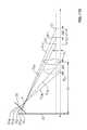
- FIG. 1is a schematic diagram illustrating how vertical and horizontal objects in the real world are viewed by a vehicular camera
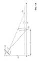
- FIG. 2is a schematic diagram illustrating how the movement of vertical and horizontal objects in the real world are viewed differently by a vehicular camera;
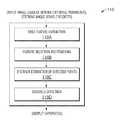
- FIG. 3is a system block diagram of an object detection algorithm according to a preferred embodiment
- FIG. 4is a flowchart of a software module employed by the object detection algorithm
- FIG. 5is a graph illustrating derivatives of an exemplary single dimension function
- FIG. 6is an image frame provided vehicular camera which sees a vertical object and a horizontal object
- FIG. 7is an edge image of FIG. 6 ;
- FIG. 8is composite image showing the image of FIG. 6 with associated edge detection contours
- FIGS. 9A and 9Bare schematic diagrams illustrating the function of a block detection algorithm
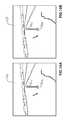
- FIGS. 10A and 10Bare successive image frames provided by a vehicular camera which has moved relative to an object seen by the camera;
- FIG. 11A-11Care schematic diagrams illustrating the operation of an object height detection filter employed by the object detection algorithm.
- FIG. 12is a flowchart of a software module employed by the object detection algorithm.
- a vector or a matrixis represented in bold face, while a scalar entity is represented in a regular face.
- the lower caseis used to denote the dimensions and pixel locations in two dimensional image space.
- the collection of all the pixels in an imagecan be denoted as f and a pixel at column x and row y in the image f can be represented as f (x, y).
- the coordinates of a point in the three-dimensional worldare represented using the upper case.
- a point on the groundcan be represented in its vector form as X, or also as [X w , Y w , Z w ].
- FIG. 3shows a system block diagram of a preferred obstacle detection system 100 .
- the inputs to system 100include the image frames 102 from the vehicular camera (not explicitly shown) and vehicle CAN (controller area network) data 104 such as the instantaneous speed of the vehicle and its steering angle.
- vehicle CANcontroller area network
- knowledge of the vehicle speedallows for the optimization of the tracking of feature points and assessing the priority of the detected obstacles and the steering angle can be used for estimating and predicting the relative trajectory of the detected obstacles.
- the system 100also has or receives information 105 about the camera. This includes intrinsic camera parameters such as its principal or central point, focal length, and lens map and extrinsic parameters such as the position of the camera.
- the lens maprefers to the characteristic description of the particular lens being used in the system which describes the behavior of the lens and allows for the generation of the output angle of the light given any input incidence angle.
- the system 100is operated in conjunction with a dynamic calibration system that is capable of dynamically ascertaining the translation position and rotational angles of the camera in the field so that any deviations in the position of the camera from a nominal position/angle over time are accounted for.
- the preferred calibration systemis described in Applicant's PCT Application No. PCT/CA2012/000056, titled “Method and System for Dynamically Calibrating Vehicular Cameras” and filed contemporaneously herewith, and published Nov. 1, 2012 as International Publication No. WO 2012/145818, the contents of which are incorporated by reference herein in their entirety.
- the system 100outputs one or more detected objects 106 (if any).
- the detected objects 106are output as an array of data structures indicating: object centroid; object bounding box (position and breadth); and an estimated distance from the vehicle.
- a differential, gradient-based, segmentation module 110receives the input information 102 - 105 .
- the module 110uses the input image frames to hypothesize or postulate the existence of an object by detecting and isolating objects from the background, within a predefined region of interest (ROI).
- the module 110filters the postulated objects to discern those which have dimensions above a defined height threshold. This is an important practical consideration because most real life objects that pose any threat to the vehicle (or to a pedestrian) have a significant vertical component. This module thus generates initial object hypotheses at output 116 which can be further refined and processed for final output.
- the segmentation module 110is based on a differential gradient based pseudo-stereo effect, which has the following features:
- the segmentation module 110includes the following functional blocks, discussed in turn below: edge feature extraction 110 A; feature selection and tracking 1108 ; physical distance estimation of detected points 110 C; and obstacle detection 110 D.
- the edge detection block 110 Auses the contours of objects as a means to segment them from the background image.
- An objectcan be assumed to be bound by its contour or its edge, which can be extracted using the gradient operator.
- edge detection block 110 Auses the “Laplacian of Gaussian (LoG)” method as known in the art per se. This method combines Gaussian filtering with the Laplacian for edge detection.
- Laplacian of Gaussian edge detectionThere are three main steps in Laplacian of Gaussian edge detection: filtering, enhancement, and detection.
- Gaussian filteringis used for smoothing and the second derivative of which is used for the enhancement step.
- the detection criterionis the presence of a zero crossing in the second derivative with a corresponding large peak in the first derivative.
- noiseis first reduced by convoluting the image with a Gaussian filter which removes isolated noise points and small structures. Those pixels, that have locally maximum gradient in the zero crossing of the second derivative, are considered as edges by the edge detector. To avoid detection of insignificant edges, only the zero crossings whose corresponding first derivative is above some threshold, are selected as edge point. The edge direction is obtained using the direction in which zero crossing occurs.
- ⁇ and *are the gradient and convolution operators, respectively.
- ⁇is the standard deviation of the smoothing function g( )
- x and yare the location column and the row index, respectively
- f(x,y)represents the pixel at column x and row y in the input image
- FIG. 7shows an example of an edge image 140 obtained by using the LoG operator on an input image 138 shown in FIG. 6 .
- each object or group of objectscan be identified by its edge.
- the feature selection and tracking block 110 Bassumes that the bottom of the each objects lies on the ground while the top of the object is either on the ground or not, depending if the object is flat or has a three-dimensional shape. Most preferably the top and bottom of each contour are selected as the points of interest in the image frame which need to be investigated to determine if the object is above a certain threshold of height or not. These topmost and bottommost points of each edge contour are then tracked from the current frame to the next frame to find their corresponding location in the next frame. For example, FIG. 8 shows the top and bottom feature points of interest O 1t and O 1b which are tracked across frames. (Note that the feature points O 1t or O 1b may each comprise multiple pixels.)
- the feature selection and tracking block 110 Bpreferably also selects and processes a set of additional feature points along the contour.
- FIG. 9Ashows as an example a feature point 152 selected by the feature selection and tracking block 110 B that consists of a 3 ⁇ 3 pixel array in image frame 150 .
- the pixel array 152has a middle position at pixel position j,k.
- the feature selection and tracking block 110 Bestablishes a macro-block 162 centered on the position of the selected feature point 152 .
- the size of the macro-block 162is based on the estimated degree of movement of the feature point/area to be tracked, and in this example encompasses a 10 ⁇ 10 array centered at pixel position j,k.
- a search window 164is defined.
- the feature selection and tracking block 110 Bslides the search window 164 in a raster fashion one pixel at a time to find a contiguous array of pixels in the macro-block 162 whose values are the closest match to the values of the selected feature point 152 .
- the closest matchis preferably defined based on a minimum absolute error criterion.
- a hierarchical searchmay be performed if the search window 164 is larger than a default size. In this manner, the position of the selected feature point 152 may be tracked to a new location, for example to pixel position p,q as indicated in FIG. 9 .
- the distance estimation block 110 Ccalculates the physical distances to the selected feature points in the ground plane.
- x i[ x p y p 1] T
- a selected pixel locationis de-warped using the distortion function of the lens, which is one of the intrinsic parameters provided in input 105 .
- every image pointcan be expressed as a 3D Plucker line matrix, which correlates to one of the rays running through the camera focal point and impinging upon the image plane (see FIG. 1 ).
- the intersection point of the Plucker line matrix and the ground planeis needed.
- HHomography matrix
- Hthe Homography matrix
- Pthe inverse of the projection matrix
- ⁇ PKRT ⁇
- ⁇ K[ - f p 0 axisX 0 f p axisY 0 0 1 ]
- R[ cos ⁇ ⁇ ⁇ sin ⁇ ⁇ ⁇ 0 - sin ⁇ ⁇ ⁇ cos ⁇ ⁇ ⁇ 0 0 1 ] ⁇ [ cos ⁇ ⁇ ⁇ 0 - sin ⁇ ⁇ ⁇ 0 1 0 sin ⁇ ⁇ ⁇ 0 cos ⁇ ⁇ ⁇ ] ⁇ [ 1 0 0 0 cos ⁇ ⁇ ⁇ sin ⁇ ⁇ ⁇ 0 - sin ⁇ ⁇ ⁇ cos ⁇ ⁇ ⁇ ] ⁇
- ⁇ T[ 1 0 0 - t 1 0 1 0 - t 2 0 0 1 - t 3 ]
- f and pare the focal length of the lens and the pixel size of the sensor, respectively.
- axisX and axisYare the column and row coordinates of the optical center on the image plane.
- ⁇ , ⁇ , and ⁇represent the angles of rotation around X, Y, and Z axes, respectively, and t 1 , t 2 , and t 3 are the translations along X, Y, and Z axes, respectively.
- the object detection block 110 Dfilters the segmented objects based on the estimated real height of the objects. Those objects that are estimated to have a real height greater than a selected threshold are considered to be relevant objects worth tracking, whereas those objects that are estimated to have a real height less than a selected threshold are considered to be irrelevant objects not worth tracking.
- the object detection block 110 Dassumes that there is some relative motion between the object and the camera, i.e., either the camera moves or the object itself moves with respect to the camera.
- FIGS. 10A and 10Billustrate two images frames 170 , 172 in which the camera has moved and thus shows the relative displacement of the object in the image. Since the objects are solid connected entities, it is fair to assume that the real-world distance traversed by the bottommost point on the object, O 1b ( FIG. 10A ) would be the same as that of the topmost point of the object, O 1t .
- the object detection block 110 Duse this as the basis for detecting if the topmost point of the object is above a certain height threshold, T, or not.
- the output of the segmentation module 110is fed in to a hypothesis evaluation stage 118 .
- This stageevaluates the postulated objects and multiple hypotheses which could belong to the same object are combined to form a single hypothesis or postulated object.
- Stage 122temporary hypotheses assignment—tracks postulated objects over time.
- the postulated objects from stage 118are further evaluated using the predicted hypotheses from the previous image frame.
- the corresponding hypothesesare assigned to the current frame where a match is found. However, if no match is found between the predicted hypothesis and the current estimated hypothesis, then a new hypothesis is instantiated.
- Stage 126is a distance and trajectory estimation block. Before the physical distance of the pixel locations can be estimated at step 128 , the fish-eye distortion of the lens needs to be corrected. See FIG. 12 . For this correction, the lens distortion is modeled as a fifth order polynomial and using this polynomial, each point in the captured image which needs further processing is de-warped.
- the de-warped points used for estimating the distance of postulated objectsare preferably the bottommost points of the objects which are assumed to lie on the ground plane. These points can be used to estimate the distance of the objects from the camera and this distance can then be translated to the vehicle coordinates. This allows the further processing of relevant postulated objects based on their relative distance to the vehicle.
- the distance estimation of the same postulated object across multiple framesis subject to small variations owing to real world, non-ideal conditions.
- these estimated distancesare filtered using a Kalman filter which can smooth out instantaneous variations.
- the same filtercan also be used to predict the location of the object in the next frame and thus help predict the trajectory of the object, which is computed at step 132 ( FIG. 3 ).
- a modified Kalman filteris preferably used, which has the following order of steps:
- Stage 136provides a hypothesis prediction. Based on the predicted physical location of the object, the location of each hypothesis in the next frame is estimated by projecting the distances back to the image plane. These projected pixel locations can then be used for the temporal assignation of the hypotheses in the next frame.
- the system outputis provided at stage 106 . Based on the trajectory estimation of each object, if the detected object is in the path of the vehicle, or poses a threat to the vehicle, then the object is output using its centroid as well as its bounding region or contour. This output may be displayed visually on a display screen or the like mounted in the vehicle and may be accompanied by audible warnings such as an alarm or voice, or by tactile feedback such as a buzz in the steering wheel. In addition, in the event the system detects an imminent crash by virtue of an obstacle being immediately in the path of the vehicle various pre-emptive actions may be taken such as automated braking or tensioning of seat belts.
Landscapes
- Engineering & Computer Science (AREA)
- Theoretical Computer Science (AREA)
- Physics & Mathematics (AREA)
- General Physics & Mathematics (AREA)
- Multimedia (AREA)
- Computer Vision & Pattern Recognition (AREA)
- Data Mining & Analysis (AREA)
- Signal Processing (AREA)
- Artificial Intelligence (AREA)
- Bioinformatics & Cheminformatics (AREA)
- Bioinformatics & Computational Biology (AREA)
- Evolutionary Biology (AREA)
- Evolutionary Computation (AREA)
- General Engineering & Computer Science (AREA)
- Life Sciences & Earth Sciences (AREA)
- Image Analysis (AREA)
- Mechanical Engineering (AREA)
- Geometry (AREA)
Abstract
Description
The present application is a continuation of U.S. patent application Ser. No. 15/406,860, filed Jan. 16, 2017, now U.S. Pat. No. 10,043,082, which is a continuation of U.S. patent application Ser. No. 14/113,415, filed Oct. 23, 2013, now U.S. Pat. No. 9,547,795, which is a 371 U.S. national phase application of PCT Application No. PCT/CA2012/000057, filed Jan. 20, 2012, which claims priority to U.S. Provisional Patent Application No. 61/478,717, filed Apr. 25, 2011.
The invention relates to the field of image processing, and more particularly to a method and system for discerning three-dimensional objects using relative motion between the camera and the objects, and an object detection system based on same.
Many vehicles now incorporate one or more obstacle detection system which use cameras to provide a field of view of the roadway and surrounding environment. The obstacle detection systems process the video stream or sequence of image frames provided by the camera in an attempt to ascertain the existence of an obstacle in the path of vehicle. Obstacle detection algorithms do this by attempting identify a variety of objects localized in one or more predefined regions of interest in the captured field of view, determine whether or not such objects are real, and estimate their path relative to the vehicle to determine whether or not such objects will indeed become obstacles.
The conventional approach to solving such a problem is to develop a series of classifiers and detectors to detect a group of predefined objects. The classifiers work in a cascade or in a parallel fashion to detect image content such as pedestrians, vehicles and geometrically shaped objects such as balls and poles. Such systems may require significant computational resources provided by expensive signal processors. In addition, in such a system, all the objects that need to be detected have to be defined in the development stage and require extensive training for the classifiers. Such a process is expensive and time consuming and might not be generic enough with respect to all possible different objects that might be encountered in the real world.
In order to overcome some of the above mentioned shortcomings, the invention proposes a more generic approach which does not depend upon the design of specific classifiers. Instead, the invention uses the relative motion between the vehicle and the surrounding environment to identify whether or not detected objects are relevant. This approach uses a single image sensor and can be employed for detecting generic objects.
Generally speaking, the invention utilizes the principle that spaced apart physical points that in reality have a vertical dimension will move at different rates when projected to the image plane provided by the vehicular camera, whereas spaced apart physical points that in reality lie only horizontally along the ground plane will move at the same rate when projected to the image plane. Using this principle the invention is able to rapidly distinguish between three dimensional objects that could be relevant to the obstacle detection analysis and irrelevant two dimensional objects that, for example, may be pavement markings or artifacts such as shadows.
The foregoing principle will be better understood with reference toFIGS. 1 and 2 . Referring toFIG. 1 , the vehicular camera establishes animage plane 20. The camera has a focal point f through which all light rays pass.Axis 21 is a normal projection to theimage plane 20.Axis 22 represents the real vertical plane, andaxis 24 represents the ground plane (a horizontal plane corresponding to the roadway). An object lies in the camera field of view. The object has a first point seen byimage pixel 26, corresponding toray 28, and a second point, seen byimage pixel 27, corresponding toray 29. This object may be either avertical object 30 or a horizontal object40 (lying along the ground plane22) because thevertical object 30 has a first point P1 lying along theray 28 and thehorizontal object 40 also has a first point G1 lying along theray 28, and likewise thevertical object 30 has a second point P2 lying along theray 29 and thehorizontal object 40 also has a second point G2 lying along theray 29. The camera sees only two vertically spaced points atpixels rays pixel
However, referring additionally toFIG. 2 , if there is relative motion between the object and the image plane additional information can be garnered to be able to differentiate between a vertically oriented object and a horizontally oriented object. Consider again the horizontallyoriented object 40 which lies on the ground plane. It has two opposing edge points that lie at initial positions G1, G2. (To the camera, these two points could also correspond to points P1 and H ofvertical object 30.) If thehorizontal object 40 moves relative to the camera by a real distance d, then the edge points will move to positions G1′, G2′. With the height and angular orientation of the camera known, it is possible to calculate the distance moved in the ground plane by the end points, i.e., the distance between G1 to G1′ and between G2 to G2. As the object is presumed to be of constant length for at least a short period of time, the distance between G1 and G1′ will be d and the distance between G2 to G2′ will also be d.
Now consider thevertical object 30. It has two opposing edge points that lie at initial positions P1, P2. The point P1, lying alongray 28, projects onto the ground plane at point G1 as previously discussed. Point P2 in this example lies along the ground plane (but it need not). Let thevertical object 30 move relative to the camera by a real distance d. The top edge point moves from position P1 to position P1′, and the bottom edge point moves from position P2 to P2′. Now calculate the distance moved in the ground plane by these end points. P1 projects onto the ground plane at point G1. Point P1′ projects onto the ground plane at point X. So, a distance calculation in the ground plane between points P1 and P1′ effectively yields a result computing the distance between G1 and X, resulting in a much larger distance d++. On the other hand, P2 and P2′ are located on the ground plane so the distance between them will be computed as d. The change d++in the ground plane between P1 and P1′ differs considerably from the changed between P2 and P2′, thus enabling a vertical object to be distinguished from an object lying substantially along the ground plane.
The principle holds for distinguishing between an object lying substantially along any selected real horizontal plane and an object lying generally transverse to the selected horizontal plane. Likewise, the principle applies even when the vertical object does not touch the selected real horizontal plane because vertically spaced apart points will move at different rates when projected onto the selected horizontal plane.
In the preferred obstacle detection system described in greater detail below, a vehicular camera is utilized to capture a video stream or sequence of image frames. The image frames are processed by an image processor which executes an obstacle detection algorithm. The preferred system then processes the images to extract edges therein. (An example of a road image10 and its edge image12 can be seen inFIGS. 3 and 4 respectively.)
The preferred system processes the edge images to identify potential objects preferably within a region of interest (ROI) in the image frame. Objects (obstacles or not) are identified by their boundaries or contours. If an object moves across successive image frames, the edges of such an object will also move and so edge based features are used to identify the location of the objects and are also used to track the objects across frames. However, owing to environmental effects and low contrast, it is possible that the edges of an object are not always isolated from other objects or the general background. In order to make the object localization more reliable, the preferred system examines different features such as color and texture cues, in conjunction with the edges, in order to detect and isolate objects from one another.
The isolated objects could be actual three dimensional objects or they could be two dimensional objects on the ground such as shadows or pavement markings. Using a single monocular image sensor, it can be quite difficult to differentiate one type of object from another. However, if there is relative motion between these objects and the camera, then using the principles outlined above the preferred system can estimate which of the detected objects are above a certain specified height threshold and which detected objects are not (such as markings on the ground). Accordingly, the preferred system examines the motion of at least two different feature points in the edge image of each object across image frames. If there is relative motion between the camera and the object, for the same physical distances traveled, points lying at different physical heights will have different rates of change in the image plane (termed “differential-gradient effect”). Thus, if the selected feature points in the edge image of an isolated object do not have different rates of change, within a tolerance, the preferred system deems that object to be an irrelevant two dimensional object. Similarly, if the selected feature points in the edge image of an isolated object do have different rates of change, within a tolerance, the preferred system deems that object to be relevant and estimates the relative path of that object to determine whether or not it will become an obstacle to the vehicle.
Thus, one aspect of the invention provides a method of obstacle detection. In this method, a vehicle is provisioned with a camera having an external field of view and a set of image frames provided by the camera are acquired whilst the vehicle is in motion. The image frames define an image plane having a vertical aspect and a horizontal aspect. The relevancy of an object is determined by (i) selecting first and second feature points from the object that are spaced apart vertically in a first image frame; (ii) tracking the positions of the first and second feature points over at least a second image frame; and (iii) deciding the object to be relevant if the first and second feature points move dissimilar distances in physical space, within a tolerance, and deciding the object to be irrelevant otherwise. The motion of relevant objects is then estimated to determine if any relevant object is likely to become an obstacle to the vehicle.
In practice, an edge detection is preferably carried out on the set of images frames and one or more objects are isolated based on their edge contours. The most desirable feature points for tracking across frames are the topmost and bottommost pixel points of any given isolated object as these can be used to estimate the relative physical displacement of the object. For this estimated displacement of the object, by comparing the estimated pixel movement of the topmost detected point of the object with the actual pixel movement of the same point, the object can be determined to be a relevant object.
In addition, in practice, a given pixel is preferably position is de-warped to account for lens distortion prior to determining a physical location corresponding to the given pixel position.
The foregoing and other aspects of the invention will be better understood with respect to the attached drawings, wherein:
For reference purposes, the following mathematical nomenclature is used in this description. A vector or a matrix is represented in bold face, while a scalar entity is represented in a regular face. The lower case is used to denote the dimensions and pixel locations in two dimensional image space. Thus, the collection of all the pixels in an image can be denoted as f and a pixel at column x and row y in the image f can be represented as f (x, y). The coordinates of a point in the three-dimensional world are represented using the upper case. A point on the ground can be represented in its vector form as X, or also as [Xw, Yw, Zw].
Thesystem 100 outputs one or more detected objects106 (if any). The detected objects106 are output as an array of data structures indicating: object centroid; object bounding box (position and breadth); and an estimated distance from the vehicle.
A differential, gradient-based,segmentation module 110 receives the input information102-105. At aninitial stage 112 themodule 110 uses the input image frames to hypothesize or postulate the existence of an object by detecting and isolating objects from the background, within a predefined region of interest (ROI). At asubsequent stage 114 themodule 110 filters the postulated objects to discern those which have dimensions above a defined height threshold. This is an important practical consideration because most real life objects that pose any threat to the vehicle (or to a pedestrian) have a significant vertical component. This module thus generates initial object hypotheses atoutput 116 which can be further refined and processed for final output.
Thesegmentation module 110 is based on a differential gradient based pseudo-stereo effect, which has the following features:
- Points lying on the same vertical axis at different planar heights (in reality) move at different pixel rates in the captured video. This allows for separation of hypothesized objects which lie on the ground plane (or other selected horizontal plane) versus those which are three dimensional in nature and pose a threat to the vehicle.
- Owing to the above principle, this approach allows the detection of even those objects which are stationary around the vehicle if the vehicle itself is moving. This allows for detection of stationary pedestrians or poles or other objects which the vehicle might be driving towards.
- Only relative motion is required between the objects and vehicle.
Referring additionally toFIG. 4 , thesegmentation module 110 includes the following functional blocks, discussed in turn below:edge feature extraction 110A; feature selection and tracking1108; physical distance estimation of detectedpoints 110C; andobstacle detection 110D.
Theedge detection block 110A uses the contours of objects as a means to segment them from the background image. An object can be assumed to be bound by its contour or its edge, which can be extracted using the gradient operator.
The edge points of an image can be detected by finding the zero crossings of the second derivative of the image intensity. The idea is illustrated for a one dimensional signal f(l)inFIG. 5 . However, calculating the 2ndderivative is very sensitive to noise. This noise should be filtered out before edge detection. To achieve this,edge detection block 110A uses the “Laplacian of Gaussian (LoG)” method as known in the art per se. This method combines Gaussian filtering with the Laplacian for edge detection.
There are three main steps in Laplacian of Gaussian edge detection: filtering, enhancement, and detection.
Gaussian filtering is used for smoothing and the second derivative of which is used for the enhancement step. The detection criterion is the presence of a zero crossing in the second derivative with a corresponding large peak in the first derivative.
In this approach, noise is first reduced by convoluting the image with a Gaussian filter which removes isolated noise points and small structures. Those pixels, that have locally maximum gradient in the zero crossing of the second derivative, are considered as edges by the edge detector. To avoid detection of insignificant edges, only the zero crossings whose corresponding first derivative is above some threshold, are selected as edge point. The edge direction is obtained using the direction in which zero crossing occurs.
The output of the LoG operator; h(x,y); is obtained by the convolution operation:
where, Δ and * are the gradient and convolution operators, respectively. σ is the standard deviation of the smoothing function g( ), x and y are the location column and the row index, respectively, and f(x,y) represents the pixel at column x and row y in the input image
Once the objects have been isolated using their contours, each object or group of objects can be identified by its edge. The feature selection and trackingblock 110B assumes that the bottom of the each objects lies on the ground while the top of the object is either on the ground or not, depending if the object is flat or has a three-dimensional shape. Most preferably the top and bottom of each contour are selected as the points of interest in the image frame which need to be investigated to determine if the object is above a certain threshold of height or not. These topmost and bottommost points of each edge contour are then tracked from the current frame to the next frame to find their corresponding location in the next frame. For example,FIG. 8 shows the top and bottom feature points of interest O1tand O1bwhich are tracked across frames. (Note that the feature points O1tor O1bmay each comprise multiple pixels.)
In addition, for more robustness, instead of just selecting the topmost and bottommost points, the feature selection and trackingblock 110B preferably also selects and processes a set of additional feature points along the contour.
Once the feature points that define the top and bottom of each object are isolated, they, as well as any other selected feature points, can be tracked across frames using a block matching algorithm. (Note that there is no need to track the entire image or object contour, only the selected feature points need to be tracked across frames.)
Any given feature point will likely subsist for least a few following image frames and with the typical frame rate of 30 fps the given feature point will move relatively slowly across image frames. The block matching algorithm establishes a macro block around the feature point and looks for a best match. For example,FIG. 9A shows as an example afeature point 152 selected by the feature selection and trackingblock 110B that consists of a 3×3 pixel array inimage frame 150. Thepixel array 152 has a middle position at pixel position j,k. In the following or otherwise subsequent image frame160 shown inFIG. 9B , the feature selection and trackingblock 110B establishes a macro-block162 centered on the position of the selectedfeature point 152. The size of the macro-block162 is based on the estimated degree of movement of the feature point/area to be tracked, and in this example encompasses a 10×10 array centered at pixel position j,k. Asearch window 164 is defined. The feature selection and tracking block110B slides thesearch window 164 in a raster fashion one pixel at a time to find a contiguous array of pixels in the macro-block162 whose values are the closest match to the values of the selectedfeature point 152. The closest match is preferably defined based on a minimum absolute error criterion. To make the search process optimal, a hierarchical search may be performed if thesearch window 164 is larger than a default size. In this manner, the position of the selectedfeature point 152 may be tracked to a new location, for example to pixel position p,q as indicated inFIG. 9 .
Thedistance estimation block 110C calculates the physical distances to the selected feature points in the ground plane.
A point in the image, xi, can be defined as
xi=[xpyp1]T
xi=[xpyp1]T
It is desired to compute the real world coordinates of this point on the ground plane, given the camera position and geometry. Before estimating the distance, a selected pixel location is de-warped using the distortion function of the lens, which is one of the intrinsic parameters provided ininput 105. In a de-warped image, every image point can be expressed as a 3D Plucker line matrix, which correlates to one of the rays running through the camera focal point and impinging upon the image plane (seeFIG. 1 ). As the projected real world is assumed to be flat or planar, the intersection point of the Plucker line matrix and the ground plane is needed. The Homography matrix, H (a 3×4 matrix), describes the projection from the image point to the world coordinate inside the plane and so the intersection point with the plane, which is defined as
Xi=H.xi
where Xi=[X1Y1Z1N1]T
Xi=H.xi
where Xi=[X1Y1Z1N1]T
The real world coordinates of the image point on the ground plane can be estimated with respect to the origin using Xias: [Xw=X1/N1; Yw=Y1/N1; Zw=Z1/N1]. To compute the real world distance of the various points using the above equation, the intrinsic and the extrinsic parameters of the camera being used are necessary. Given these parameters, the Homography matrix, H, can be estimated as the inverse of the projection matrix, P, which is defined as:
In the above equations, f and p are the focal length of the lens and the pixel size of the sensor, respectively. axisX and axisY are the column and row coordinates of the optical center on the image plane. α, β, and γ represent the angles of rotation around X, Y, and Z axes, respectively, and t1, t2, and t3are the translations along X, Y, and Z axes, respectively.
Theobject detection block 110D filters the segmented objects based on the estimated real height of the objects. Those objects that are estimated to have a real height greater than a selected threshold are considered to be relevant objects worth tracking, whereas those objects that are estimated to have a real height less than a selected threshold are considered to be irrelevant objects not worth tracking.
For height threshold verification, theobject detection block 110D assumes that there is some relative motion between the object and the camera, i.e., either the camera moves or the object itself moves with respect to the camera. For example,FIGS. 10A and 10B illustrate twoimages frames FIG. 10A ) would be the same as that of the topmost point of the object, O1t. Theobject detection block 110D use this as the basis for detecting if the topmost point of the object is above a certain height threshold, T, or not.
The steps involved in this detection are as follows:
(1) Estimate the initial distance of the object from the reference camera using the pixel location of the bottommost point, O1b, and use it with the homography matrix to estimate the real-world coordinate, D1, in the ground plane. See, for example,FIG. 11A .
(2) Track the motion of the bottommost point the object from pixel location O1bto pixel location O2band using the homography equation estimate the real-world coordinate D2of the bottommost point on the ground plane, and the distance ΔD the bottommost point has moved. See, for example,FIG. 11B .
(3) Use the Homography equation to estimate a real world coordinate of the topmost point of the object corresponding to its location O1tin the first frame. Assume that the top of the object is at a height T, which will correspond to a point DTat this height. SeeFIG. 11A .
(4) Since the top and the bottom points of the physical object move by the same distance in the real world, then presuming that the topmost point of the object it is at height T, the new real world location of the top-most point, D*T, is DT+ΔD. SeeFIG. 11B .
(5) Using the inverse of the homography equation, compute the pixel coordinate O*2Tof the top-most point after accounting for its real world displacement if it was at a height T. SeeFIG. 11B .
(6) Compare the pixel displacement of the estimated pixel location of the top most point with respect to the initial location ∥O2t*−O1t∥, with that of actual pixel location of the tracked topmost point of the object with respect to the initial location, ∥O2t−O1t∥. If ∥O2t*−O1t∥<∥O2t−O1t∥, then the topmost point of the object is above the height threshold and if ∥O2t*−O1t∥>∥O2t−O1t∥, then the topmost point of the object is below the height threshold. See, for example,FIG. 10B where the object is higher than the threshold height T and so O*2tis closer to O1tthan O2t.
The foregoing steps utilized the image plane. It should also be appreciated that the analysis can just as well be carried out in real physical space. In this methodology, as exemplified inFIG. 11C , the rays in the first and second image frames corresponding to the topmost point of the object are projected onto the selected horizontal physical plane corresponding to height T to generate real points G1 and G2. The object is deemed to be a valid object, i.e., having a height greater than T, if ∥G2−G1∥>ΔD.
It will also be understood that in the case of T=0 the selected horizontal physical plane corresponds to the ground plane.
Referring back toFIG. 3 , the output of thesegmentation module 110—postulated objects—is fed in to ahypothesis evaluation stage 118. This stage evaluates the postulated objects and multiple hypotheses which could belong to the same object are combined to form a single hypothesis or postulated object.
In addition, if a hypothesis existed in the previous frame but is not currently detected, then this hypothesis is not immediately rejected, but is held in memory for a specified number of frames to verify that the postulated object is no longer present. In case where the postulated object is actually present, the detection may be missed intermittently, and therefore this temporal processing leads to a significant reduction in the false negatives.
The de-warped points used for estimating the distance of postulated objects are preferably the bottommost points of the objects which are assumed to lie on the ground plane. These points can be used to estimate the distance of the objects from the camera and this distance can then be translated to the vehicle coordinates. This allows the further processing of relevant postulated objects based on their relative distance to the vehicle.
The distance estimation of the same postulated object across multiple frames is subject to small variations owing to real world, non-ideal conditions. Thus, these estimated distances are filtered using a Kalman filter which can smooth out instantaneous variations. The same filter can also be used to predict the location of the object in the next frame and thus help predict the trajectory of the object, which is computed at step132 (FIG. 3 ).
Owing to the nature of the problem, a modified Kalman filter is preferably used, which has the following order of steps:
- Update Step: Update the filter parameters and estimate the filtered distance of the object detected in the current frame ({circumflex over (X)}, Ŷ), using the input real world distance (X,Y). (See
FIG. 12 .) - Prediction Step: Predict the distance of the object in the next frame.
- Update Step: Update the filter parameters and estimate the filtered distance of the object detected in the current frame ({circumflex over (X)}, Ŷ), using the input real world distance (X,Y). (See
The system output is provided atstage 106. Based on the trajectory estimation of each object, if the detected object is in the path of the vehicle, or poses a threat to the vehicle, then the object is output using its centroid as well as its bounding region or contour. This output may be displayed visually on a display screen or the like mounted in the vehicle and may be accompanied by audible warnings such as an alarm or voice, or by tactile feedback such as a buzz in the steering wheel. In addition, in the event the system detects an imminent crash by virtue of an obstacle being immediately in the path of the vehicle various pre-emptive actions may be taken such as automated braking or tensioning of seat belts.
Those skilled in the art will appreciate that a variety of modifications may be made to the embodiments described herein without departing from the spirit of the invention.
Claims (20)
1. A method of distinguishing a three dimensional object from a two dimensional object using a vehicular vision system, said method comprising:
(a) disposing a camera at a vehicle, the camera having a field of view external of the vehicle;
(b) providing a control having a processor;
(c) providing to the control height of the camera at the vehicle and angular orientation of the camera at the vehicle;
(d) capturing image frames of image data via the camera while the vehicle is in motion, each of the captured image frames defining an image plane having a vertical aspect and a horizontal aspect;
(e) via processing of captured image frames by the processor, detecting by edge detection a first object present in multiple captured image frames;
(f) via processing of captured image frames by the processor, detecting by edge detection a second object present in the multiple captured image frames;
(g) for the first detected object,
(1) selecting, via the control, and responsive to processing of captured image frames by the processor, first and second feature points from the first detected object that are spaced apart in a first captured image frame of the multiple captured image frames,
(2) tracking, via the control, and responsive to processing of captured image frames by the processor, positions of the first and second feature points in at least a second captured image frame of the multiple captured image frames, and
(3) determining, via the control, and responsive to processing of captured image frames by the processor, movement of the first and second feature points over the multiple captured image frames;
(h) for the second detected object,
(1) selecting, via the control, and responsive to processing of captured image frames by the processor, third and fourth feature points from the second detected object that are spaced apart in the first captured image frame,
(2) tracking, via the control, and responsive to processing of captured image frames by the processor, positions of the third and fourth feature points in at least the second captured image frame, and
(3) determining, via the control, and responsive to processing of captured image frames by the processor, movement of the third and fourth feature points over the multiple captured image frames;
(i) comparing, via the control, movement of the first and second feature points over the multiple captured image frames to movement of the third and fourth feature points over the multiple captured image frames; and
(j) distinguishing, via the control, between the first detected object being a three dimensional object and the second detected object being a two dimensional object by determining, via the control, that movement of the first feature point over the multiple captured image frames is dissimilar to that of the second feature point and by determining, via the control, that movement of the third feature point over the multiple captured image frames is similar to that of the fourth feature point.
2. The method according toclaim 1 , comprising providing to the control a focal length of a lens of the camera.
3. The method according toclaim 1 , comprising providing to the control vehicle data of the vehicle the camera is disposed at, the vehicle data comprising speed and steering angle.
4. The method according toclaim 3 , wherein the vehicle data is provided to the control via a controller area network.
5. The method according toclaim 1 , wherein the second detected object comprises a shadow.
6. The method according toclaim 1 , wherein the second detected object comprises a pavement marking.
7. The method according toclaim 1 , wherein the second detected object comprises a ground marking.
8. The method according toclaim 1 , including unwarping a given pixel position to account for lens distortion prior to determining a physical location corresponding to the given pixel position.
9. The method according toclaim 1 , wherein the first and second feature points are portions of top and bottom edge contours of the first detected object.
10. The method according toclaim 1 , wherein the first and second feature points selected from the first detected object are spaced vertically apart in the first captured image frame.
11. The method according toclaim 1 , comprising:
estimating, via the control, from the first captured image frame, a physical distance D1of the first feature point O1bto the camera in a selected physical horizontal plane;
estimating, via the control, from the first captured image frame, a physical location DTof the second feature point O1Tassuming that the second feature point physically lies at a height T above the selected physical horizontal plane; and
estimating, via the control, from the second captured image frame, a physical distance D2of the first feature point O2bto the camera in the selected physical horizontal plane, and determining the distance ΔD between D2and D1.
12. The method according toclaim 11 , wherein the selected physical horizontal plane is the ground plane.
13. The method according toclaim 1 , comprising operating in conjunction with a dynamic calibration system that is operable to dynamically ascertain rotational angles of the camera so that any deviations over time from nominal angle are accounted for.
14. A method of distinguishing a three dimensional object from a two dimensional object using a vehicular vision system, said method comprising:
(a) disposing a camera at a vehicle, the camera having a field of view external of the vehicle;
(b) providing a control having a processor;
(c) providing to the control height of the camera at the vehicle and angular orientation of the camera at the vehicle;
(d) providing to the control a focal length of a lens of the camera;
(e) providing to the control vehicle data of the vehicle the camera is disposed at, the vehicle data comprising speed and steering angle while the vehicle is in motion;
(f) capturing image frames of image data via the camera while the vehicle is in motion, each of the captured image frames defining an image plane having a vertical aspect and a horizontal aspect;
(g) via processing of captured image frames by the processor, detecting by edge detection a first object present in multiple captured image frames;
(h) via processing of captured image frames by the processor, detecting by edge detection a second object present in the multiple captured image frames;
(i) for the first detected object,
(1) selecting, via the control, and responsive to processing of captured image frames by the processor, first and second feature points from the first detected object that are spaced apart in a first captured image frame of the multiple captured image frames,
(2) tracking, via the control, and responsive to processing of captured image frames by the processor, positions of the first and second feature points in at least a second captured image frame of the multiple captured image frames, and
(3) determining, via the control, and responsive to processing of captured image frames by the processor, movement of the first and second feature points over the multiple captured image frames;
(j) for the second detected object,
(1) selecting, via the control, and responsive to processing of captured image frames by the processor, third and fourth feature points from the second detected object that are spaced apart in the first captured image frame,
(2) tracking, via the control, and responsive to processing of captured image frames by the processor, positions of the third and fourth feature points in at least the second captured image frame, and
(3) determining, via the control, and responsive to processing of captured image frames by the processor, movement of the third and fourth feature points over the multiple captured image frames;
(k) comparing, via the control, movement of the first and second feature points over the multiple captured image frames to movement of the third and fourth feature points over the multiple captured image frames; and
(l) distinguishing, via the control, between the first detected object being a three dimensional object and the second detected object being a two dimensional object by determining, via the control, that movement of the first feature point over the multiple captured image frames is dissimilar to that of the second feature point and by determining, via the control, that movement of the third feature point over the multiple captured image frames is similar to that of the fourth feature point.
15. The method according toclaim 14 , wherein the vehicle data is provided to the control via a controller area network.
16. The method according toclaim 14 , wherein the first and second feature points are portions of top and bottom edge contours of the first detected object.
17. A method of distinguishing a three dimensional object from a two dimensional object using a vehicular vision system, said method comprising:
(a) disposing a camera at a vehicle, the camera having a field of view external of the vehicle;
(b) providing a control having a processor;
(c) providing to the control height of the camera at the vehicle and angular orientation of the camera at the vehicle;
(d) providing to the control vehicle data of the vehicle the camera is disposed at, the vehicle data comprising speed and steering angle while the vehicle is in motion, wherein the vehicle data is provided to the control via a controller area network;
(e) capturing image frames of image data via the camera while the vehicle is in motion, each of the captured image frames defining an image plane having a vertical aspect and a horizontal aspect;
(f) via processing of captured image frames by the processor, detecting by edge detection a first object present in multiple captured image frames;
(g) via processing of captured image frames by the processor, detecting by edge detection a second object present in the multiple captured image frames;
(h) for the first detected object,
(1) selecting, via the control, and responsive to processing of captured image frames by the processor, first and second feature points from the first detected object that are spaced apart in a first captured image frame of the multiple captured image frames, wherein the first and second feature points selected from the first detected object are spaced vertically apart in the first captured image frame,
(2) tracking, via the control, and responsive to processing of captured image frames by the processor, positions of the first and second feature points in at least a second captured image frame of the multiple captured image frames, and
(3) determining, via the control, and responsive to processing of captured image frames by the processor, movement of the first and second feature points over the multiple captured image frames;
(i) for the second detected object,
(1) selecting, via the control, and responsive to processing of captured image frames by the processor, third and fourth feature points from the second detected object that are spaced apart in the first captured image frame,
(2) tracking, via the control, and responsive to processing of captured image frames by the processor, positions of the third and fourth feature points in at least the second captured image frame, and
(3) determining, via the control, and responsive to processing of captured image frames by the processor, movement of the third and fourth feature points over the multiple captured image frames;
(j) comparing, via the control, movement of the first and second feature points over the multiple captured image frames to movement of the third and fourth feature points over the multiple captured image frames; and
(k) distinguishing, via the control, between the first detected object being a three dimensional object and the second detected object being a two dimensional object by determining, via the control, that movement of the first feature point over the multiple captured image frames is dissimilar to that of the second feature point and by determining, via the control, that movement of the third feature point over the multiple captured image frames is similar to that of the fourth feature point.
18. The method according toclaim 17 , wherein the second detected object comprises an object selected from the group consisting of (i) a shadow, (ii) a pavement marking and (iii) a ground marking.
19. The method according toclaim 17 , including unwarping a given pixel position to account for lens distortion prior to determining a physical location corresponding to the given pixel position.
20. The method according toclaim 17 , wherein the first and second feature points are portions of top and bottom edge contours of the first detected object.
Priority Applications (1)
| Application Number | Priority Date | Filing Date | Title |
|---|---|---|---|
| US16/055,262US10452931B2 (en) | 2011-04-25 | 2018-08-06 | Processing method for distinguishing a three dimensional object from a two dimensional object using a vehicular system |
Applications Claiming Priority (5)
| Application Number | Priority Date | Filing Date | Title |
|---|---|---|---|
| US201161478717P | 2011-04-25 | 2011-04-25 | |
| PCT/CA2012/000057WO2012145819A1 (en) | 2011-04-25 | 2012-01-20 | Image processing method for detecting objects using relative motion |
| US201314113415A | 2013-12-16 | 2013-12-16 | |
| US15/406,860US10043082B2 (en) | 2011-04-25 | 2017-01-16 | Image processing method for detecting objects using relative motion |
| US16/055,262US10452931B2 (en) | 2011-04-25 | 2018-08-06 | Processing method for distinguishing a three dimensional object from a two dimensional object using a vehicular system |
Related Parent Applications (1)
| Application Number | Title | Priority Date | Filing Date |
|---|---|---|---|
| US15/406,860ContinuationUS10043082B2 (en) | 2011-04-25 | 2017-01-16 | Image processing method for detecting objects using relative motion |
Publications (2)
| Publication Number | Publication Date |
|---|---|
| US20180341823A1 US20180341823A1 (en) | 2018-11-29 |
| US10452931B2true US10452931B2 (en) | 2019-10-22 |
Family
ID=47071511
Family Applications (3)
| Application Number | Title | Priority Date | Filing Date |
|---|---|---|---|
| US14/113,415Active2032-10-28US9547795B2 (en) | 2011-04-25 | 2012-01-20 | Image processing method for detecting objects using relative motion |
| US15/406,860ActiveUS10043082B2 (en) | 2011-04-25 | 2017-01-16 | Image processing method for detecting objects using relative motion |
| US16/055,262ActiveUS10452931B2 (en) | 2011-04-25 | 2018-08-06 | Processing method for distinguishing a three dimensional object from a two dimensional object using a vehicular system |
Family Applications Before (2)
| Application Number | Title | Priority Date | Filing Date |
|---|---|---|---|
| US14/113,415Active2032-10-28US9547795B2 (en) | 2011-04-25 | 2012-01-20 | Image processing method for detecting objects using relative motion |
| US15/406,860ActiveUS10043082B2 (en) | 2011-04-25 | 2017-01-16 | Image processing method for detecting objects using relative motion |
Country Status (2)
| Country | Link |
|---|---|
| US (3) | US9547795B2 (en) |
| WO (1) | WO2012145819A1 (en) |
Cited By (6)
| Publication number | Priority date | Publication date | Assignee | Title |
|---|---|---|---|---|
| US10733757B2 (en)* | 2018-05-10 | 2020-08-04 | Magna Electronics Inc. | Trailer assist system with estimation of 3D location of hitch |
| US12115918B2 (en) | 2022-01-31 | 2024-10-15 | Magna Mirrors Of America, Inc. | Vehicular trailering assist system with auxiliary side trailer cameras |
| US12136270B2 (en) | 2021-01-05 | 2024-11-05 | Magna Electronics Inc. | Vehicular trailer angle detection system for fifth-wheel trailers |
| US12167171B2 (en) | 2021-10-05 | 2024-12-10 | Magna Electronics Inc. | Vehicular vision system with object classification based on change in orientation of object |
| US12384295B2 (en) | 2021-01-05 | 2025-08-12 | Magna Electronics Inc. | Vehicular trailer angle detection system for fifth-wheel trailers |
| US12400353B2 (en) | 2022-05-10 | 2025-08-26 | Magna Electronics Inc. | Vehicular vision system with object detection and identification with adaptive thresholding |
Families Citing this family (61)
| Publication number | Priority date | Publication date | Assignee | Title |
|---|---|---|---|---|
| US9959595B2 (en) | 2010-09-21 | 2018-05-01 | Mobileye Vision Technologies Ltd. | Dense structure from motion |
| US9280711B2 (en) | 2010-09-21 | 2016-03-08 | Mobileye Vision Technologies Ltd. | Barrier and guardrail detection using a single camera |
| US9357208B2 (en) | 2011-04-25 | 2016-05-31 | Magna Electronics Inc. | Method and system for dynamically calibrating vehicular cameras |
| WO2012145819A1 (en) | 2011-04-25 | 2012-11-01 | Magna International Inc. | Image processing method for detecting objects using relative motion |
| US9834153B2 (en) | 2011-04-25 | 2017-12-05 | Magna Electronics Inc. | Method and system for dynamically calibrating vehicular cameras |
| US10008002B2 (en)* | 2012-02-28 | 2018-06-26 | NXP Canada, Inc. | Single-camera distance estimation |
| US8903163B2 (en)* | 2012-08-09 | 2014-12-02 | Trimble Navigation Limited | Using gravity measurements within a photogrammetric adjustment |
| TW201420398A (en)* | 2012-11-19 | 2014-06-01 | Hon Hai Prec Ind Co Ltd | System and method for monitoring traffic safety of vehicle |
| US9852341B2 (en) | 2013-02-04 | 2017-12-26 | Harman International Industries, Incorporation | Method and system for detecting moving objects |
| WO2014133868A1 (en)* | 2013-03-01 | 2014-09-04 | Gentex Corporation | Vehicle imaging system and method for categorizing objects using relative motion analysis |
| DE102013012930A1 (en)* | 2013-08-02 | 2015-02-05 | Connaught Electronics Ltd. | Method for determining a current distance and / or a current speed of a target object from a reference point in a camera image, camera system and motor vehicle |
| JP6129981B2 (en)* | 2013-10-01 | 2017-05-17 | 株式会社日立製作所 | Moving object position estimation apparatus and moving object position estimation method |
| US10095935B2 (en) | 2013-12-20 | 2018-10-09 | Magna Electronics Inc. | Vehicle vision system with enhanced pedestrian detection |
| US10210399B2 (en) | 2013-12-20 | 2019-02-19 | Magna Electronics Inc. | Vehicle vision system with image processing |
| US11081008B2 (en) | 2013-12-20 | 2021-08-03 | Magna Electronics Inc. | Vehicle vision system with cross traffic detection |
| US10525883B2 (en) | 2014-06-13 | 2020-01-07 | Magna Electronics Inc. | Vehicle vision system with panoramic view |
| EP4465256A3 (en) | 2014-06-18 | 2025-02-19 | Mobileye Vision Technologies Ltd. | Hazard detection in a scene with moving shadows |
| US11472338B2 (en) | 2014-09-15 | 2022-10-18 | Magna Electronics Inc. | Method for displaying reduced distortion video images via a vehicular vision system |
| US10442355B2 (en) | 2014-09-17 | 2019-10-15 | Intel Corporation | Object visualization in bowl-shaped imaging systems |
| US9437001B2 (en) | 2014-09-18 | 2016-09-06 | Intel Corporation | Tracking objects in bowl-shaped imaging systems |
| US10769453B2 (en)* | 2017-05-16 | 2020-09-08 | Samsung Electronics Co., Ltd. | Electronic device and method of controlling operation of vehicle |
| EP3034000A1 (en)* | 2014-12-16 | 2016-06-22 | Agfa Healthcare | Motion correction method in dual energy radiography |
| US9898671B2 (en) | 2015-05-11 | 2018-02-20 | Magna Electronics Inc. | Vehicle vision system with structure and motion estimation |
| EP3098752A1 (en)* | 2015-05-29 | 2016-11-30 | Thomson Licensing | Method and device for generating an image representative of a cluster of images |
| US10204279B2 (en) | 2015-07-30 | 2019-02-12 | Magna Electronics Inc. | Vehicle vision system with object detection |
| US10268904B2 (en) | 2015-07-31 | 2019-04-23 | Magna Electronics Inc. | Vehicle vision system with object and lane fusion |
| CN105046235B (en)* | 2015-08-03 | 2018-09-07 | 百度在线网络技术(北京)有限公司 | The identification modeling method and device of lane line, recognition methods and device |
| JP6671152B2 (en)* | 2015-11-19 | 2020-03-25 | 日立建機株式会社 | Abnormality detection device of self-position estimation device and vehicle |
| CN105513056B (en)* | 2015-11-30 | 2018-06-19 | 天津津航技术物理研究所 | Join automatic calibration method outside vehicle-mounted monocular infrared camera |
| US10407047B2 (en)* | 2015-12-07 | 2019-09-10 | Magna Electronics Inc. | Vehicle control system with target vehicle trajectory tracking |
| DE102016201304A1 (en)* | 2016-01-28 | 2017-08-03 | Robert Bosch Gmbh | Apparatus and method for detecting a curb in an environment of a vehicle and curb control system for a vehicle |
| US10453217B2 (en) | 2016-03-24 | 2019-10-22 | Magna Electronics Inc. | Targetless vehicle camera calibration system |
| US10227119B2 (en)* | 2016-04-15 | 2019-03-12 | Lockheed Martin Corporation | Passive underwater odometry using a video camera |
| US10380765B2 (en) | 2016-08-17 | 2019-08-13 | Magna Electronics Inc. | Vehicle vision system with camera calibration |
| DE102016119030A1 (en)* | 2016-10-07 | 2018-04-12 | Dr. Ing. H.C. F. Porsche Aktiengesellschaft | Method and system for distance determination |
| US10198818B2 (en)* | 2016-10-12 | 2019-02-05 | Intel Corporation | Complexity reduction of human interacted object recognition |
| EP4155128B1 (en)* | 2016-12-09 | 2025-02-12 | Kyocera Corporation | Imaging apparatus, image processing apparatus, display system, and vehicle |
| US10504241B2 (en) | 2016-12-19 | 2019-12-10 | Magna Electronics Inc. | Vehicle camera calibration system |
| CN107176100A (en)* | 2017-05-12 | 2017-09-19 | 深圳市京弘全智能科技股份有限公司 | Car-mounted terminal and its distance-finding method with distance measurement function |
| US10803323B2 (en) | 2017-05-16 | 2020-10-13 | Samsung Electronics Co., Ltd. | Electronic device and method of detecting driving event of vehicle |
| KR102060662B1 (en)* | 2017-05-16 | 2019-12-30 | 삼성전자주식회사 | Electronic device and method for detecting a driving event of vehicle |
| US10304210B2 (en)* | 2017-05-25 | 2019-05-28 | GM Global Technology Operations LLC | Method and apparatus for camera calibration |
| US10647282B2 (en) | 2017-11-06 | 2020-05-12 | Magna Electronics Inc. | Vehicle vision system with undercarriage cameras |
| US10026209B1 (en)* | 2017-12-21 | 2018-07-17 | Capital One Services, Llc | Ground plane detection for placement of augmented reality objects |
| TWI660310B (en)* | 2018-08-06 | 2019-05-21 | 財團法人資訊工業策進會 | Method and electronic apparatus for comparing tracking object |
| US11257225B2 (en)* | 2019-10-25 | 2022-02-22 | 7-Eleven, Inc. | Sensor mapping to a global coordinate system using homography |
| JP7191671B2 (en)* | 2018-12-19 | 2022-12-19 | フォルシアクラリオン・エレクトロニクス株式会社 | CALIBRATION DEVICE, CALIBRATION METHOD |
| TWI719409B (en)* | 2019-02-23 | 2021-02-21 | 和碩聯合科技股份有限公司 | Tracking system and tracking method thereof |
| DE102019105293A1 (en)* | 2019-03-01 | 2020-09-03 | Hochschule RheinMain University of Applied Sciences Wiesbaden Rüsselsheim Geisenheim | Estimation of the movement of an image position |
| CN112052866B (en)* | 2019-06-05 | 2024-08-06 | 株式会社理光 | Image verification method and device and computer readable storage medium |
| JP7322651B2 (en)* | 2019-10-14 | 2023-08-08 | 株式会社デンソー | Obstacle recognition device |
| US11176709B2 (en)* | 2019-10-17 | 2021-11-16 | Toyota Research Institute, Inc. | Systems and methods for self-supervised scale-aware training of a model for monocular depth estimation |
| US11508156B2 (en) | 2019-12-27 | 2022-11-22 | Magna Electronics Inc. | Vehicular vision system with enhanced range for pedestrian detection |
| JP7615141B2 (en)* | 2020-05-25 | 2025-01-16 | ソニーセミコンダクタソリューションズ株式会社 | Information processing device, information processing method, and program |
| CN113744277B (en)* | 2020-05-29 | 2024-07-02 | 广州汽车集团股份有限公司 | A video de-shaking method and system based on local path optimization |
| EP4224456A4 (en)* | 2020-10-01 | 2024-04-03 | Sony Group Corporation | INFORMATION PROCESSING DEVICE, INFORMATION PROCESSING METHOD, PROGRAM AND PROJECTION DEVICE |
| US11967122B2 (en)* | 2021-04-19 | 2024-04-23 | Argo AI, LLC | Context aware verification for sensor pipelines |
| US12412420B2 (en)* | 2021-06-25 | 2025-09-09 | Intel Corporation | Apparatus, systems, and methods for microphone gain control for electronic user devices |
| CN113570575B (en)* | 2021-07-28 | 2025-01-07 | 精英数智科技股份有限公司 | A drilling depth statistics method and system based on target detection |
| TWI788967B (en)* | 2021-08-24 | 2023-01-01 | 瑞昱半導體股份有限公司 | Image processing method and image processing circuit |
| KR20240103749A (en)* | 2022-12-27 | 2024-07-04 | 현대자동차주식회사 | Vehicle and control method thereof |
Citations (322)
| Publication number | Priority date | Publication date | Assignee | Title |
|---|---|---|---|---|
| US4720790A (en) | 1984-05-21 | 1988-01-19 | Kabushiki Kaisha Toyota Chuo Kenkyusho | Apparatus for controlling steer angle of rear wheels of vehicle |
| US4987357A (en) | 1989-12-18 | 1991-01-22 | General Motors Corporation | Adaptive motor vehicle cruise control |
| US4991054A (en) | 1988-05-13 | 1991-02-05 | Pacific Scientific Company | Time-delay outdoor lighting control systems |
| US5001558A (en) | 1985-06-11 | 1991-03-19 | General Motors Corporation | Night vision system with color video camera |
| US5003288A (en) | 1988-10-25 | 1991-03-26 | Nartron Corporation | Ambient light sensing method and apparatus |
| US5012082A (en) | 1989-03-01 | 1991-04-30 | Hamamatsu Photonics K.K. | Two-dimensional incident position detector device for light or radiation |
| US5016977A (en) | 1989-02-06 | 1991-05-21 | Essilor International-Compagnie Generale | Optical lens for correcting astigmatism |
| US5027200A (en) | 1990-07-10 | 1991-06-25 | Edward Petrossian | Enhanced viewing at side and rear of motor vehicles |
| US5027001A (en) | 1989-08-29 | 1991-06-25 | Torbert William F | Moisture sensitive automatic windshield wiper and headlight control device |
| US5044706A (en) | 1990-02-06 | 1991-09-03 | Hughes Aircraft Company | Optical element employing aspherical and binary grating optical surfaces |
| US5055668A (en) | 1989-05-24 | 1991-10-08 | Nissan Motor Co., Ltd. | Photo-sensor cell suitable for IC chip |
| US5059877A (en) | 1989-12-22 | 1991-10-22 | Libbey-Owens-Ford Co. | Rain responsive windshield wiper control |
| US5064274A (en) | 1987-08-26 | 1991-11-12 | Siegel-Robert, Inc. | Automatic automobile rear view mirror assembly |
| US5072154A (en) | 1990-03-13 | 1991-12-10 | Chen Min Hsiung | Automatic luminosity control device for car and motor bicycle headlamps |
| US5086253A (en) | 1990-10-15 | 1992-02-04 | Lawler Louis N | Automatic headlight dimmer apparatus |
| US5096287A (en) | 1990-03-15 | 1992-03-17 | Aisin Seiki K.K. | Video camera for an automobile |
| US5097362A (en) | 1989-07-19 | 1992-03-17 | Lynas Robert M | Rearview mirror targeting and repositioning system |
| US5121200A (en) | 1990-07-06 | 1992-06-09 | Choi Seung Lyul | Travelling monitoring system for motor vehicles |
| US5124549A (en) | 1990-10-15 | 1992-06-23 | Lectron Products, Inc. | Automatic headlamp dimmer with optical baffle |
| US5130709A (en) | 1987-12-28 | 1992-07-14 | Aisin Aw Co., Ltd. | Navigation apparatus for vehicle |
| US5168378A (en) | 1992-02-10 | 1992-12-01 | Reliant Laser Corporation | Mirror with dazzle light attenuation zone |
| US5170374A (en) | 1981-05-13 | 1992-12-08 | Hitachi, Ltd. | Semiconductor memory |
| US5172235A (en) | 1990-04-23 | 1992-12-15 | Volkswagen Ag | Imaging system for simultaneous viewing of two images |
| US5177685A (en) | 1990-08-09 | 1993-01-05 | Massachusetts Institute Of Technology | Automobile navigation system using real time spoken driving instructions |
| US5182502A (en) | 1991-05-06 | 1993-01-26 | Lectron Products, Inc. | Automatic headlamp dimmer |
| US5184956A (en) | 1990-02-20 | 1993-02-09 | Codes Rousseau | Method and device for training in the driving of vehicles |
| US5189561A (en) | 1991-03-28 | 1993-02-23 | Hong Sun T | Automatic oscillating vehicle mirror |
| US5193029A (en) | 1991-11-19 | 1993-03-09 | Donnelly Corporation | Single sensor adaptive drive circuit for rearview mirror system |
| US5193000A (en) | 1991-08-28 | 1993-03-09 | Stereographics Corporation | Multiplexing technique for stereoscopic video system |
| US5204778A (en) | 1992-04-06 | 1993-04-20 | Gentex Corporation | Control system for automatic rearview mirrors |
| US5208701A (en) | 1991-12-24 | 1993-05-04 | Xerox Corporation | Wobble correction lens with binary diffractive optic surface and refractive cylindrical surface |
| US5245422A (en) | 1991-06-28 | 1993-09-14 | Zexel Corporation | System and method for automatically steering a vehicle within a lane in a road |
| US5255442A (en) | 1991-12-20 | 1993-10-26 | Donnelly Corporation | Vehicle compass with electronic sensor |
| US5276389A (en) | 1991-12-14 | 1994-01-04 | Leopold Kostal Gmbh & Co. Kg | Method of controlling a windshield wiper system |
| US5285060A (en) | 1992-12-15 | 1994-02-08 | Donnelly Corporation | Display for automatic rearview mirror |
| US5289182A (en) | 1991-10-16 | 1994-02-22 | Ii Bc-Sys | Electronic anti-collison device carried on board a vehicle |
| US5289321A (en) | 1993-02-12 | 1994-02-22 | Secor James O | Consolidated rear view camera and display system for motor vehicle |
| US5305012A (en) | 1992-04-15 | 1994-04-19 | Reveo, Inc. | Intelligent electro-optical system and method for automatic glare reduction |
| US5307136A (en) | 1991-10-22 | 1994-04-26 | Fuji Jukogyo Kabushiki Kaisha | Distance detection system for vehicles |
| US5309137A (en) | 1991-02-26 | 1994-05-03 | Mitsubishi Denki Kabushiki Kaisha | Motor car traveling control device |
| US5313072A (en) | 1993-02-16 | 1994-05-17 | Rockwell International Corporation | Optical detector for windshield wiper control |
| US5325386A (en) | 1992-04-21 | 1994-06-28 | Bandgap Technology Corporation | Vertical-cavity surface emitting laser assay display system |
| US5325096A (en) | 1992-08-14 | 1994-06-28 | Vorad Safety Systems, Inc. | Smart blind spot sensor |
| US5331312A (en) | 1991-08-23 | 1994-07-19 | Matsushita Electric Industrial Co., Ltd. | Obstacle-detecting apparatus |
| US5336980A (en) | 1992-12-10 | 1994-08-09 | Leopold Kostal Gmbh & Co. | Apparatus and method for controlling a windshield wiping system |
| US5341437A (en) | 1989-12-22 | 1994-08-23 | Honda Giken Kogyo Kabushiki Kaisha | Method of determining the configuration of a path for motor vehicle |
| US5351044A (en) | 1992-08-12 | 1994-09-27 | Rockwell International Corporation | Vehicle lane position detection system |
| US5355118A (en) | 1991-07-11 | 1994-10-11 | Nissan Motor Co., Ltd. | Vehicle collision alert system |
| US5374852A (en) | 1993-09-17 | 1994-12-20 | Parkes; Walter B. | Motor vehicle headlight activation apparatus for inclement weather conditions |
| US5386285A (en) | 1992-02-28 | 1995-01-31 | Mitsubishi Denki Kabushiki Kaisha | Obstacle detecting device for a vehicle |
| US5394333A (en) | 1991-12-23 | 1995-02-28 | Zexel Usa Corp. | Correcting GPS position in a hybrid naviation system |
| US5406395A (en) | 1993-11-01 | 1995-04-11 | Hughes Aircraft Company | Holographic parking assistance device |
| US5410346A (en) | 1992-03-23 | 1995-04-25 | Fuji Jukogyo Kabushiki Kaisha | System for monitoring condition outside vehicle using imaged picture by a plurality of television cameras |
| US5414257A (en) | 1991-04-23 | 1995-05-09 | Introlab Pty Limited | Moisture sensor for detecting moisture on a windshield |
| US5414461A (en) | 1991-11-15 | 1995-05-09 | Nissan Motor Co., Ltd. | Vehicle navigation apparatus providing simultaneous forward and rearward views |
| US5416318A (en) | 1991-10-03 | 1995-05-16 | Hegyi; Dennis J. | Combined headlamp and climate control sensor having a light diffuser and a light modulator |
| US5416478A (en) | 1992-03-12 | 1995-05-16 | Funai Electric Co., Ltd. | Car navigation system |
| US5424952A (en) | 1993-03-26 | 1995-06-13 | Mitsubishi Denki Kabushiki Kaisha | Vehicle-surroundings monitoring apparatus |
| US5426294A (en) | 1992-05-27 | 1995-06-20 | Koito Manufacturing Co., Ltd. | Glare sensor for a vehicle |
| US5430431A (en) | 1994-01-19 | 1995-07-04 | Nelson; Louis J. | Vehicle protection system and method |
| US5434407A (en) | 1993-08-23 | 1995-07-18 | Gentex Corporation | Automatic rearview mirror incorporating light pipe |
| US5440428A (en) | 1993-09-30 | 1995-08-08 | Hughes Aircraft Company | Automotive instrument 3-D virtual image display |
| US5444478A (en) | 1992-12-29 | 1995-08-22 | U.S. Philips Corporation | Image processing method and device for constructing an image from adjacent images |
| US5451822A (en) | 1991-03-15 | 1995-09-19 | Gentex Corporation | Electronic control system |
| US5457493A (en) | 1993-09-15 | 1995-10-10 | Texas Instruments Incorporated | Digital micro-mirror based image simulation system |
| US5461361A (en) | 1994-03-11 | 1995-10-24 | Chrysler Corporation | Automotive instrument panel apparatus |
| US5461357A (en) | 1992-01-29 | 1995-10-24 | Mazda Motor Corporation | Obstacle detection device for vehicle |
| US5469298A (en) | 1991-08-14 | 1995-11-21 | Prince Corporation | Reflective display at infinity |
| US5471515A (en) | 1994-01-28 | 1995-11-28 | California Institute Of Technology | Active pixel sensor with intra-pixel charge transfer |
| US5475494A (en) | 1992-12-22 | 1995-12-12 | Mitsubishi Denki Kabushiki Kaisha | Driving environment surveillance apparatus |
| US5497306A (en) | 1993-02-01 | 1996-03-05 | Donnelly Corporation | Exterior vehicle security light |
| US5498866A (en) | 1993-06-01 | 1996-03-12 | Leopold Kostal Gmbh & Co. Kg | Optoelectronic sensor for detecting moisture on a windshield with means to compensate for a metallic layer in the windshield |
| US5500766A (en) | 1995-05-04 | 1996-03-19 | Stonecypher; Bob | Blind spot side mirror |
| US5510983A (en) | 1992-11-13 | 1996-04-23 | Yazaki Corporation | On-vehicle display |
| US5515448A (en) | 1992-07-28 | 1996-05-07 | Yazaki Corporation | Distance measuring apparatus of a target tracking type |
| US5521633A (en) | 1992-09-25 | 1996-05-28 | Yazaki Corporation | Motor vehicle obstacle monitoring system using optical flow processing |
| US5528698A (en) | 1995-03-27 | 1996-06-18 | Rockwell International Corporation | Automotive occupant sensing device |
| US5530420A (en) | 1993-12-27 | 1996-06-25 | Fuji Jukogyo Kabushiki Kaisha | Running guide apparatus for vehicle capable of keeping safety at passing through narrow path and the method thereof |
| US5529138A (en) | 1993-01-22 | 1996-06-25 | Shaw; David C. H. | Vehicle collision avoidance system |
| US5535314A (en) | 1991-11-04 | 1996-07-09 | Hughes Aircraft Company | Video image processor and method for detecting vehicles |
| US5537003A (en) | 1994-04-08 | 1996-07-16 | Gentex Corporation | Control system for automotive vehicle headlamps and other vehicle equipment |
| US5539397A (en) | 1993-03-26 | 1996-07-23 | Honda Giken Kogyo Kabushiki Kaisha | Driving control system for vehicle |
| US5541590A (en) | 1992-08-04 | 1996-07-30 | Takata Corporation | Vehicle crash predictive and evasive operation system by neural networks |
| US5550677A (en) | 1993-02-26 | 1996-08-27 | Donnelly Corporation | Automatic rearview mirror system using a photosensor array |
| US5555555A (en) | 1993-01-19 | 1996-09-10 | Aisin Seiki Kabushiki Kaisha | Apparatus which detects lines approximating an image by repeatedly narrowing an area of the image to be analyzed and increasing the resolution in the analyzed area |
| US5568027A (en) | 1995-05-19 | 1996-10-22 | Libbey-Owens-Ford Co. | Smooth rain-responsive wiper control |
| US5574443A (en) | 1994-06-22 | 1996-11-12 | Hsieh; Chi-Sheng | Vehicle monitoring apparatus with broadly and reliably rearward viewing |
| US5581464A (en) | 1992-08-14 | 1996-12-03 | Vorad Safety Systems, Inc. | Recording of operational events in an automotive vehicle |
| US5594222A (en) | 1994-10-25 | 1997-01-14 | Integrated Controls | Touch sensor and control circuit therefor |
| US5610756A (en) | 1990-11-26 | 1997-03-11 | Donnelly Corporation | Electrochromic mirror for vehicles |
| US5614788A (en) | 1995-01-31 | 1997-03-25 | Autosmart Light Switches, Inc. | Automated ambient condition responsive daytime running light system |
| US5619370A (en) | 1994-03-28 | 1997-04-08 | Guinosso; Patrick J. | Optical system for viewing a remote location |
| US5632092A (en) | 1991-12-20 | 1997-05-27 | Donnelly Corporation | Compensation system for electronic compass |
| US5634709A (en) | 1994-12-27 | 1997-06-03 | Murakami Corporation | Inner mirror of a vehicle having a display device |
| US5642299A (en) | 1993-09-01 | 1997-06-24 | Hardin; Larry C. | Electro-optical range finding and speed detection system |
| US5648835A (en) | 1992-09-22 | 1997-07-15 | Olympus Optical Co., Ltd. | Optical system for monitor cameras to be mounted on vehicles |
| US5650944A (en) | 1993-03-24 | 1997-07-22 | Fuji Jukogyo Kabushiki Kaisha | Shutter speed control method and system |
| US5660454A (en) | 1992-08-28 | 1997-08-26 | Toyota Jidosha Kabushiki Kaisha | Apparatus and method for controlling light distribution of headlamp |
| US5661303A (en) | 1996-05-24 | 1997-08-26 | Libbey-Owens-Ford Co. | Compact moisture sensor with collimator lenses and prismatic coupler |
| US5666028A (en) | 1994-04-06 | 1997-09-09 | Gentex Corporation | Automobile headlamp and running light control system |
| US5670935A (en) | 1993-02-26 | 1997-09-23 | Donnelly Corporation | Rearview vision system for vehicle including panoramic view |
| US5677851A (en) | 1994-12-15 | 1997-10-14 | Novell, Inc. | Method and apparatus to secure digital directory object changes |
| US5699044A (en) | 1988-12-05 | 1997-12-16 | Prince Corporation | Electrical control system for vehicle options |
| US5724316A (en) | 1995-09-26 | 1998-03-03 | Delco Electronics Corporation | GPS based time determining system and method |
| US5732379A (en) | 1994-11-25 | 1998-03-24 | Itt Automotive Europe Gmbh | Brake system for a motor vehicle with yaw moment control |
| US5737226A (en) | 1995-06-05 | 1998-04-07 | Prince Corporation | Vehicle compass system with automatic calibration |
| US5761094A (en) | 1996-01-18 | 1998-06-02 | Prince Corporation | Vehicle compass system |
| US5760931A (en) | 1992-12-14 | 1998-06-02 | Nippondenso Co., Ltd. | Image display unit |
| US5760828A (en) | 1994-06-03 | 1998-06-02 | Idesa Accesorios, S.A. | Back-vision system for vehicles |
| US5765116A (en) | 1993-08-28 | 1998-06-09 | Lucas Industries Public Limited Company | Driver assistance system for a vehicle |
| US5765118A (en) | 1995-03-30 | 1998-06-09 | Toyota Jidosha Kabushiki Kaisha | Estimation method of movement state variable in turning of automotive vehicle |
| US5781437A (en) | 1992-04-21 | 1998-07-14 | Ibp Pietzsch Gmbh | Control system for controlling vehicles |
| US5786772A (en) | 1996-03-22 | 1998-07-28 | Donnelly Corporation | Vehicle blind spot detection display system |
| US5790403A (en) | 1994-07-12 | 1998-08-04 | Honda Giken Kogyo Kabushiki Kaisha | Lane image processing system for vehicle |
| US5790973A (en) | 1995-12-19 | 1998-08-04 | Prince Corporation | Last exit warning system |
| US5793420A (en) | 1994-10-28 | 1998-08-11 | Schmidt; William P. | Video recording system for vehicle |
| US5793308A (en) | 1992-07-02 | 1998-08-11 | Sensorvision Technologies, L.L.C. | Vehicular position monitoring system with integral mirror video display |
| US5796094A (en) | 1993-02-26 | 1998-08-18 | Donnelly Corporation | Vehicle headlight control using imaging sensor |
| US5835255A (en) | 1986-04-23 | 1998-11-10 | Etalon, Inc. | Visible spectrum modulator arrays |
| US5837994A (en) | 1997-04-02 | 1998-11-17 | Gentex Corporation | Control system to automatically dim vehicle head lamps |
| US5844505A (en) | 1997-04-01 | 1998-12-01 | Sony Corporation | Automobile navigation system |
| US5845000A (en) | 1992-05-05 | 1998-12-01 | Automotive Technologies International, Inc. | Optical identification and monitoring system using pattern recognition for use with vehicles |
| US5844682A (en) | 1994-03-25 | 1998-12-01 | Omron Corporation | Optical sensor device |
| US5850176A (en) | 1996-07-10 | 1998-12-15 | Fuji Jukogyo Kabushiki Kaisha | Drive assist system for vehicle |
| US5848802A (en) | 1992-05-05 | 1998-12-15 | Automotive Technologies International, Inc. | Vehicle occupant position and velocity sensor |
| US5850254A (en) | 1994-07-05 | 1998-12-15 | Hitachi, Ltd. | Imaging system for a vehicle which compares a reference image which includes a mark which is fixed to said vehicle to subsequent images |
| US5867591A (en) | 1995-04-21 | 1999-02-02 | Matsushita Electric Industrial Co., Ltd. | Method of matching stereo images and method of measuring disparity between these image |
| US5878357A (en) | 1996-09-03 | 1999-03-02 | Ford Global Technologies, Inc. | Method and apparatus for vehicle yaw rate estimation |
| US5878370A (en) | 1995-12-01 | 1999-03-02 | Prince Corporation | Vehicle compass system with variable resolution |
| US5877897A (en) | 1993-02-26 | 1999-03-02 | Donnelly Corporation | Automatic rearview mirror, vehicle lighting control and vehicle interior monitoring system using a photosensor array |
| US5877707A (en) | 1997-01-17 | 1999-03-02 | Kowalick; Thomas M. | GPS based seat belt monitoring system & method for using same |
| US5884212A (en) | 1994-04-15 | 1999-03-16 | Thomson-Csf | Process for monitoring traffic for automatic vehicle incident detection |
| US5883739A (en) | 1993-10-04 | 1999-03-16 | Honda Giken Kogyo Kabushiki Kaisha | Information display device for vehicle |
| US5890021A (en) | 1996-12-05 | 1999-03-30 | Canon Kabushiki Kaisha | Distance detecting device, focus state detecting device and camera having same |
| US5896085A (en) | 1995-09-07 | 1999-04-20 | Toyota Jidosha Kabushiki Kaisha | Apparatus for controlling light distributions of head lamps |
| US5899956A (en) | 1998-03-31 | 1999-05-04 | Advanced Future Technologies, Inc. | Vehicle mounted navigation device |
| US5915800A (en) | 1995-06-19 | 1999-06-29 | Fuji Jukogyo Kabushiki Kaisha | System for controlling braking of an automotive vehicle |
| US5923027A (en) | 1997-09-16 | 1999-07-13 | Gentex Corporation | Moisture sensor and windshield fog detector using an image sensor |
| US5924212A (en) | 1996-10-09 | 1999-07-20 | Donnelly Corporation | Electronic compass |
| US5959555A (en) | 1996-08-23 | 1999-09-28 | Furuta; Yoshihisa | Apparatus for checking blind spots of vehicle |
| US5963247A (en) | 1994-05-31 | 1999-10-05 | Banitt; Shmuel | Visual display systems and a system for producing recordings for visualization thereon and methods therefor |
| US5990649A (en) | 1997-07-01 | 1999-11-23 | Murakami Corporation | Control device for quick angle adjustment of rearview mirror |
| US5990469A (en) | 1997-04-02 | 1999-11-23 | Gentex Corporation | Control circuit for image array sensors |
| US6020704A (en) | 1997-12-02 | 2000-02-01 | Valeo Electrical Systems, Inc. | Windscreen sensing and wiper control system |
| US6049171A (en) | 1998-09-18 | 2000-04-11 | Gentex Corporation | Continuously variable headlamp control |
| US6052124A (en) | 1997-02-03 | 2000-04-18 | Yissum Research Development Company | System and method for directly estimating three-dimensional structure of objects in a scene and camera motion from three two-dimensional views of the scene |
| US6066933A (en) | 1998-10-02 | 2000-05-23 | Ponziana; Richard L. | Rain sensing system and method having automatically registered and oriented rain sensor |
| US6084519A (en) | 1993-05-07 | 2000-07-04 | Control Devices, Inc. | Multi-function light sensor for vehicle |
| US6100799A (en) | 1996-06-17 | 2000-08-08 | Bayerische Motoren Werke Aktiengesellschaft | Process and device for indicating braking power or delay in cars |
| US6144022A (en) | 1999-03-15 | 2000-11-07 | Valeo Electrical Systems, Inc. | Rain sensor using statistical analysis |
| US6175300B1 (en) | 1998-09-03 | 2001-01-16 | Byron K. Kendrick | Blind spot viewing system |
| US6178034B1 (en) | 1996-04-10 | 2001-01-23 | Donnelly Corporation | Electrochromic devices |
| US6201642B1 (en) | 1999-07-27 | 2001-03-13 | Donnelly Corporation | Vehicular vision system with a wide angle lens including a diffractive element |
| US6223114B1 (en) | 1998-03-20 | 2001-04-24 | Daimlerchrysler Ag | Process for controlling driving dynamics of a street vehicle |
| US6227689B1 (en) | 1999-09-28 | 2001-05-08 | Donnelly Corporation | Illumination device for exterior mirror |
| US6250148B1 (en) | 1998-01-07 | 2001-06-26 | Donnelly Corporation | Rain sensor mount for use in a vehicle |
| US6266442B1 (en) | 1998-10-23 | 2001-07-24 | Facet Technology Corp. | Method and apparatus for identifying objects depicted in a videostream |
| US6266082B1 (en) | 1995-12-19 | 2001-07-24 | Canon Kabushiki Kaisha | Communication apparatus image processing apparatus communication method and image processing method |
| US6285393B1 (en) | 1993-09-08 | 2001-09-04 | Sumitomo Electric Industries, Ltd. | Object recognition apparatus and method |
| US6294989B1 (en) | 1998-12-16 | 2001-09-25 | Donnelly Corporation | Tire inflation assistance monitoring system |
| US6297781B1 (en) | 1999-02-16 | 2001-10-02 | Gentex Corporation | Rearview mirror with integrated microwave receiver |
| US6310611B1 (en) | 1996-12-10 | 2001-10-30 | Touchsensor Technologies, Llc | Differential touch sensor and control circuit therefor |
| US6313454B1 (en) | 1999-07-02 | 2001-11-06 | Donnelly Corporation | Rain sensor |
| US6317057B1 (en) | 2000-04-03 | 2001-11-13 | Hyundai Motor Company | Method for detecting lane deviation of vehicle |
| US6320282B1 (en) | 1999-01-19 | 2001-11-20 | Touchsensor Technologies, Llc | Touch switch with integral control circuit |
| US6333759B1 (en) | 1999-03-16 | 2001-12-25 | Joseph J. Mazzilli | 360 ° automobile video camera system |
| US20020015153A1 (en) | 2000-07-27 | 2002-02-07 | Downs Michael John | Jamin-type interferometers and components therefor |
| US6353392B1 (en) | 1997-10-30 | 2002-03-05 | Donnelly Corporation | Rain sensor with fog discrimination |
| US6370329B1 (en) | 1999-01-20 | 2002-04-09 | Zeiss Optronik Gmbh | Stabilized camera |
| US20020044065A1 (en) | 2000-03-27 | 2002-04-18 | Quist Chad D. | Interactive automotive rearvision system |
| US6392315B1 (en) | 1999-04-05 | 2002-05-21 | Delphi Technologies, Inc. | Compensation circuit for an automotive ignition sensing system |
| US6396397B1 (en) | 1993-02-26 | 2002-05-28 | Donnelly Corporation | Vehicle imaging system with stereo imaging |
| US6411204B1 (en) | 1999-11-15 | 2002-06-25 | Donnelly Corporation | Deceleration based anti-collision safety light control for vehicle |
| US6420975B1 (en) | 1999-08-25 | 2002-07-16 | Donnelly Corporation | Interior rearview mirror sound processing system |
| US6424273B1 (en) | 2001-03-30 | 2002-07-23 | Koninklijke Philips Electronics N.V. | System to aid a driver to determine whether to change lanes |
| US6430303B1 (en) | 1993-03-31 | 2002-08-06 | Fujitsu Limited | Image processing apparatus |
| US20020113873A1 (en) | 2001-02-20 | 2002-08-22 | Williams Michael R. | Rear vision system for large vehicles |
| US6442465B2 (en) | 1992-05-05 | 2002-08-27 | Automotive Technologies International, Inc. | Vehicular component control systems and methods |
| US6477464B2 (en) | 2000-03-09 | 2002-11-05 | Donnelly Corporation | Complete mirror-based global-positioning system (GPS) navigation solution |
| US6498620B2 (en) | 1993-02-26 | 2002-12-24 | Donnelly Corporation | Vision system for a vehicle including an image capture device and a display system having a long focal length |
| US6497503B1 (en) | 2001-06-21 | 2002-12-24 | Ford Global Technologies, Inc. | Headlamp system with selectable beam pattern |
| US6534884B2 (en) | 1998-12-16 | 2003-03-18 | Donnelly Corporation | Proximity sensing system for vehicles |
| US6539306B2 (en) | 2001-06-15 | 2003-03-25 | Gentex Corporation | Automotive mirror with integrated Loran components |
| US6547133B1 (en) | 1998-04-08 | 2003-04-15 | Donnelly Corporation | Vehicle mounted remote transaction interface system |
| US6553130B1 (en) | 1993-08-11 | 2003-04-22 | Jerome H. Lemelson | Motor vehicle warning and control system and method |
| US6574033B1 (en) | 2002-02-27 | 2003-06-03 | Iridigm Display Corporation | Microelectromechanical systems device and method for fabricating same |
| US6589625B1 (en) | 2001-08-01 | 2003-07-08 | Iridigm Display Corporation | Hermetic seal and method to create the same |
| US6594583B2 (en) | 2000-01-31 | 2003-07-15 | Yazaki Corporation | Side-monitoring apparatus for motor vehicle |
| US20030137586A1 (en) | 2002-01-22 | 2003-07-24 | Infinite Innovations, Inc. | Vehicle video switching system and method |
| US6611610B1 (en) | 1997-04-02 | 2003-08-26 | Gentex Corporation | Vehicle lamp control |
| US6636258B2 (en) | 2001-10-19 | 2003-10-21 | Ford Global Technologies, Llc | 360° vision system for a vehicle |
| US6650455B2 (en) | 1994-05-05 | 2003-11-18 | Iridigm Display Corporation | Photonic mems and structures |
| US20030222982A1 (en) | 2002-03-28 | 2003-12-04 | Hamdan Majil M. | Integrated video/data information system and method for application to commercial vehicles to enhance driver awareness |
| US6674562B1 (en) | 1994-05-05 | 2004-01-06 | Iridigm Display Corporation | Interferometric modulation of radiation |
| US6672731B2 (en) | 2000-11-20 | 2004-01-06 | Donnelly Corporation | Vehicular rearview mirror with blind spot viewing system |
| US6680792B2 (en) | 1994-05-05 | 2004-01-20 | Iridigm Display Corporation | Interferometric modulation of radiation |
| US6690268B2 (en) | 2000-03-02 | 2004-02-10 | Donnelly Corporation | Video mirror systems incorporating an accessory module |
| US20040032321A1 (en) | 2002-04-19 | 2004-02-19 | Mcmahon Martha A. | Vehicle imaging system |
| US6700605B1 (en) | 1998-05-15 | 2004-03-02 | Matsushita Electric Industrial Co., Ltd. | Apparatus for monitoring |
| US6704621B1 (en) | 1999-11-26 | 2004-03-09 | Gideon P. Stein | System and method for estimating ego-motion of a moving vehicle using successive images recorded along the vehicle's path of motion |
| US6710908B2 (en) | 1994-05-05 | 2004-03-23 | Iridigm Display Corporation | Controlling micro-electro-mechanical cavities |
| US6711474B1 (en) | 2000-01-24 | 2004-03-23 | G. Victor Treyz | Automobile personal computer systems |
| US6714331B2 (en) | 2001-04-20 | 2004-03-30 | Microvision, Inc. | Scanned imaging apparatus with switched feeds |
| US6717610B1 (en) | 1998-11-25 | 2004-04-06 | Donnelly Corporation | Wide angle image capture system for vehicle |
| US6735506B2 (en) | 1992-05-05 | 2004-05-11 | Automotive Technologies International, Inc. | Telematics system |
| US6741377B2 (en) | 2002-07-02 | 2004-05-25 | Iridigm Display Corporation | Device having a light-absorbing mask and a method for fabricating same |
| US6744353B2 (en) | 1999-12-15 | 2004-06-01 | Sjoenell Goeran | Blind spot detector |
| US20040114381A1 (en) | 2002-12-13 | 2004-06-17 | Ford Global Technologies, Llc | Adaptive vehicle communication controlled lighting system |
| US6757109B2 (en) | 1999-07-27 | 2004-06-29 | Donnelly Corporation | Plastic lens system for vehicle imaging system |
| US6762867B2 (en) | 1999-08-05 | 2004-07-13 | Microvision, Inc. | Scanned display with plurality of scanning assemblies |
| US6794119B2 (en) | 2002-02-12 | 2004-09-21 | Iridigm Display Corporation | Method for fabricating a structure for a microelectromechanical systems (MEMS) device |
| US6795221B1 (en) | 1999-08-05 | 2004-09-21 | Microvision, Inc. | Scanned display with switched feeds and distortion correction |
| US6819231B2 (en) | 2002-02-05 | 2004-11-16 | Donnelly Hohe Gmbh & Co. Kg | Parking and/or maneuvering assistance device |
| US6823241B2 (en) | 2000-10-02 | 2004-11-23 | Nissan Motor Co., Ltd. | Lane recognition apparatus for vehicle |
| US6824281B2 (en) | 2002-01-31 | 2004-11-30 | Donnelly Corporation | Vehicle accessory module |
| US20050078389A1 (en) | 2003-09-05 | 2005-04-14 | Kulas Jerry M. | Interior rearview mirror assembly |
| US6882287B2 (en) | 2001-07-31 | 2005-04-19 | Donnelly Corporation | Automotive lane change aid |
| US6889161B2 (en) | 2001-04-12 | 2005-05-03 | Robert Bosch Gmbh | Method for recognizing a change in lane of a vehicle |
| US6909753B2 (en) | 2001-12-05 | 2005-06-21 | Koninklijke Philips Electronics, N.V. | Combined MPEG-4 FGS and modulation algorithm for wireless video transmission |
| US20050134983A1 (en) | 2003-11-26 | 2005-06-23 | Lynam Niall R. | Mirror reflective element for a vehicle |
| US20050165550A1 (en)* | 2004-01-23 | 2005-07-28 | Ryuzo Okada | Obstacle detection apparatus and a method therefor |
| US6946978B2 (en) | 2002-04-25 | 2005-09-20 | Donnelly Corporation | Imaging system for vehicle |
| US20050264891A1 (en) | 2004-06-01 | 2005-12-01 | Uken John T | Mirror assembly for vehicle |
| US6975775B2 (en) | 2002-03-06 | 2005-12-13 | Radiant Imaging, Inc. | Stray light correction method for imaging light and color measurement system |
| US6989736B2 (en) | 2002-09-25 | 2006-01-24 | Donnelly Hohe Gmbh & Co. Kg | Monitoring device for a motor vehicle |
| US20060018511A1 (en) | 2000-03-20 | 2006-01-26 | Stam Joseph S | System for controlling vehicle equipment |
| US7004606B2 (en) | 2002-04-23 | 2006-02-28 | Donnelly Corporation | Automatic headlamp control |
| US20060061008A1 (en) | 2004-09-14 | 2006-03-23 | Lee Karner | Mounting assembly for vehicle interior mirror |
| US7038577B2 (en) | 2002-05-03 | 2006-05-02 | Donnelly Corporation | Object detection system for vehicle |
| US20060103727A1 (en) | 2004-11-17 | 2006-05-18 | Huan-Chin Tseng | Vehicle back up camera |
| US20060111841A1 (en)* | 2004-11-19 | 2006-05-25 | Jiun-Yuan Tseng | Method and apparatus for obstacle avoidance with camera vision |
| US7062300B1 (en) | 2000-11-09 | 2006-06-13 | Ki Il Kim | Cellular phone holder with charger mounted to vehicle dashboard |
| US7065432B2 (en) | 2003-10-02 | 2006-06-20 | Daimlerchrysler Ag | Device for improving the visibility conditions in a motor vehicle |
| US7079017B2 (en) | 2001-04-23 | 2006-07-18 | Lang-Mekra North America, Llc | Warning device in motor vehicles |
| US20060164221A1 (en) | 2005-01-18 | 2006-07-27 | Jensen John M | Sensor-activated controlled safety or warning light mounted on or facing toward rear of vehicle |
| US7085637B2 (en) | 1997-10-22 | 2006-08-01 | Intelligent Technologies International, Inc. | Method and system for controlling a vehicle |
| US7111968B2 (en) | 1998-09-15 | 2006-09-26 | Gentex Corporation | Systems and components for enhancing rear vision from a vehicle |
| US7113867B1 (en) | 2000-11-26 | 2006-09-26 | Mobileye Technologies Limited | System and method for detecting obstacles to vehicle motion and determining time to contact therewith using sequences of images |
| US7116246B2 (en) | 2001-10-03 | 2006-10-03 | Maryann Winter | Apparatus and method for sensing the occupancy status of parking spaces in a parking lot |
| US7123168B2 (en) | 2002-04-25 | 2006-10-17 | Donnelly Corporation | Driving separation distance indicator |
| US20060250501A1 (en) | 2005-05-06 | 2006-11-09 | Widmann Glenn R | Vehicle security monitor system and method |
| US7136753B2 (en) | 2002-12-05 | 2006-11-14 | Denso Corporation | Object recognition apparatus for vehicle, inter-vehicle control apparatus, and distance measurement apparatus |
| US7145519B2 (en) | 2002-04-18 | 2006-12-05 | Nissan Motor Co., Ltd. | Image display apparatus, method, and program for automotive vehicle |
| US7149613B2 (en) | 2001-03-05 | 2006-12-12 | Gentex Corporation | Image processing system to control vehicle headlamps or other vehicle equipment |
| US7151996B2 (en) | 2000-04-14 | 2006-12-19 | Mobileye Technologies Limited | System and method for generating a model of the path of a roadway from an image recorded by a camera |
| US20060290479A1 (en) | 2005-06-28 | 2006-12-28 | Honda Motor Co., Ltd. | Driver-assistance vehicle |
| US7161616B1 (en) | 1999-04-16 | 2007-01-09 | Matsushita Electric Industrial Co., Ltd. | Image processing device and monitoring system |
| US7195381B2 (en) | 2001-01-23 | 2007-03-27 | Donnelly Corporation | Vehicle interior LED lighting system |
| US7202776B2 (en) | 1997-10-22 | 2007-04-10 | Intelligent Technologies International, Inc. | Method and system for detecting objects external to a vehicle |
| US20070104476A1 (en) | 2005-11-04 | 2007-05-10 | Konica Minolta Photo Imaging, Inc. | Camera system and controller |
| JP2007129560A (en) | 2005-11-04 | 2007-05-24 | Toyota Motor Corp | Object detection device |
| US7227611B2 (en) | 2004-08-23 | 2007-06-05 | The Boeing Company | Adaptive and interactive scene illumination |
| US20070274566A1 (en)* | 2006-05-24 | 2007-11-29 | Nissan Motor Co., Ltd. | Pedestrian detector and pedestrian detecting method |
| US7365769B1 (en) | 2000-07-06 | 2008-04-29 | Donald Mager | Activating a vehicle's own brake lights and/or brakes when brake lights are sensed in front of the vehicle, including responsively to the proximity of, and/or rate of closure with, a forward vehicle |
| US7370983B2 (en) | 2000-03-02 | 2008-05-13 | Donnelly Corporation | Interior mirror assembly with display |
| US7460951B2 (en) | 2005-09-26 | 2008-12-02 | Gm Global Technology Operations, Inc. | System and method of target tracking using sensor fusion |
| US7480149B2 (en) | 2004-08-18 | 2009-01-20 | Donnelly Corporation | Accessory module for vehicle |
| US7490007B2 (en) | 2000-03-02 | 2009-02-10 | Donnelly Corporation | Video mirror system for a vehicle |
| US7492281B2 (en) | 2005-07-06 | 2009-02-17 | Donnelly Corporation | Vehicle exterior mirror assembly with blind spot indicator |
| US7502048B2 (en) | 2001-10-15 | 2009-03-10 | Panasonic Corporation | Method for arranging cameras in a vehicle surroundings monitoring system |
| US20090093938A1 (en) | 2007-10-09 | 2009-04-09 | Denso Corporation | Speed control system for vehicles |
| US7526103B2 (en) | 2004-04-15 | 2009-04-28 | Donnelly Corporation | Imaging system for vehicle |
| US20090113509A1 (en) | 2007-10-30 | 2009-04-30 | Av Tech Corporation | Video system, video transmitter, video receiver and control method for the same |
| US7532109B2 (en) | 2005-08-02 | 2009-05-12 | Nissan Motor Co., Ltd. | Vehicle obstacle verification system |
| US20090177347A1 (en) | 2008-01-04 | 2009-07-09 | Karsten Breuer | Vehicle driver assistance system and method |
| US7566851B2 (en) | 2006-03-24 | 2009-07-28 | Mobileye Technologies Ltd. | Headlight, taillight and streetlight detection |
| US20090189783A1 (en)* | 2008-01-29 | 2009-07-30 | Omron Corporation | Image processing device, image processing method, and program |
| US7581859B2 (en) | 2005-09-14 | 2009-09-01 | Donnelly Corp. | Display device for exterior rearview mirror |
| US7592928B2 (en) | 2005-06-07 | 2009-09-22 | Nissan Motor Co., Ltd. | Image display device and method |
| US20090244361A1 (en) | 2005-10-28 | 2009-10-01 | Magna Electronics Inc. | Camera module for vehicle vision system |
| US20090243824A1 (en) | 2008-03-31 | 2009-10-01 | Magna Mirrors Of America, Inc. | Interior rearview mirror system |
| US20090252377A1 (en)* | 2006-10-06 | 2009-10-08 | Aisin Seiki Kabushiki Kaisha | Mobile object recognizing device, mobile object recognizing method, and computer program thereof |
| US20090265069A1 (en) | 2008-04-17 | 2009-10-22 | Herman Desbrunes | Land vehicle braking system |
| US20090279740A1 (en)* | 2006-09-13 | 2009-11-12 | Pioneer Corporation | Distance measuring device and method, and computer program |
| US20090295181A1 (en) | 2004-12-15 | 2009-12-03 | Magna Donnelly Electronics Naas Limited | Accessory module system for a vehicle window |
| US7639149B2 (en) | 2006-05-09 | 2009-12-29 | Denso Corporation | Automatic lighting device and method for controlling light |
| JP2010020476A (en) | 2008-07-09 | 2010-01-28 | Nissan Motor Co Ltd | Object detection device and object detection method |
| US20100020170A1 (en) | 2008-07-24 | 2010-01-28 | Higgins-Luthman Michael J | Vehicle Imaging System |
| JP2010038907A (en) | 2008-07-08 | 2010-02-18 | Nissan Motor Co Ltd | Device and method for detecting object |
| US7681960B2 (en) | 2003-10-28 | 2010-03-23 | Continental Teves Ag & Co. Ohg | Method and system for improving the driving behavior of a vehicle |
| US20100097469A1 (en) | 2008-10-16 | 2010-04-22 | Magna Mirrors Of America, Inc. | Interior mirror assembly with display |
| US7720580B2 (en) | 2004-12-23 | 2010-05-18 | Donnelly Corporation | Object detection system for vehicle |
| US7724962B2 (en) | 2006-07-07 | 2010-05-25 | Siemens Corporation | Context adaptive approach in vehicle detection under various visibility conditions |
| US7777611B2 (en) | 2006-11-06 | 2010-08-17 | Donnelly Corporation | Display device for exterior rearview mirror |
| US7786898B2 (en) | 2006-05-31 | 2010-08-31 | Mobileye Technologies Ltd. | Fusion of far infrared and visible images in enhanced obstacle detection in automotive applications |
| US20100228437A1 (en) | 2005-12-27 | 2010-09-09 | Daisuke Hanzawa | Vehicle and steering control device for vehicle |
| WO2010119329A2 (en) | 2009-04-15 | 2010-10-21 | Toyota Jidosha Kabushiki Kaisha | Object detection device |
| US7855755B2 (en) | 2005-11-01 | 2010-12-21 | Donnelly Corporation | Interior rearview mirror assembly with display |
| US7881496B2 (en) | 2004-09-30 | 2011-02-01 | Donnelly Corporation | Vision system for vehicle |
| US7914187B2 (en) | 2007-07-12 | 2011-03-29 | Magna Electronics Inc. | Automatic lighting system with adaptive alignment function |
| US20110115912A1 (en) | 2007-08-31 | 2011-05-19 | Valeo Schalter Und Sensoren Gmbh | Method and system for online calibration of a video system |
| US7949486B2 (en) | 2005-10-28 | 2011-05-24 | Hi-Key Limited | Method and apparatus for calibrating an image capturing device, and a method and apparatus for outputting image frames from sequentially captured image frames with compensation for image capture device offset |
| US7952490B2 (en) | 2005-02-22 | 2011-05-31 | Continental Temic Microelectronic GmbH | Method for identifying the activation of the brake lights of preceding vehicles |
| US7965336B2 (en) | 2002-11-14 | 2011-06-21 | Donnelly Corporation | Imaging system for vehicle |
| US8013780B2 (en) | 2007-01-25 | 2011-09-06 | Magna Electronics Inc. | Radar sensing system for vehicle |
| US20110216201A1 (en) | 2008-10-01 | 2011-09-08 | Hi-Key Limited | method and a system for calibrating an image capture device |
| US8027029B2 (en) | 2007-11-07 | 2011-09-27 | Magna Electronics Inc. | Object detection and tracking system |
| US8058977B2 (en) | 2006-10-24 | 2011-11-15 | Donnelly Corporation | Exterior mirror having a display that can be viewed by a host driver or drivers of other vehicles |
| US8064643B2 (en) | 2006-12-06 | 2011-11-22 | Mobileye Technologies Limited | Detecting and recognizing traffic signs |
| US8082101B2 (en) | 2004-04-08 | 2011-12-20 | Mobileye Technologies Ltd. | Collision warning system |
| US20120044066A1 (en) | 2010-08-23 | 2012-02-23 | Harman Becker Automotive Systems Gmbh | System for vehicle braking detection |
| US20120062743A1 (en) | 2009-02-27 | 2012-03-15 | Magna Electronics Inc. | Alert system for vehicle |
| US8164628B2 (en) | 2006-01-04 | 2012-04-24 | Mobileye Technologies Ltd. | Estimating distance to an object using a sequence of images recorded by a monocular camera |
| US8254635B2 (en) | 2007-12-06 | 2012-08-28 | Gideon Stein | Bundling of driver assistance systems |
| US20120218412A1 (en) | 2009-06-12 | 2012-08-30 | Magna Electronics Inc. | Scalable integrated electronic control unit for vehicle |
| US20120245817A1 (en) | 2011-03-23 | 2012-09-27 | Tk Holdings Inc. | Driver assistance system |
| US20120262340A1 (en) | 2011-04-12 | 2012-10-18 | Magna Electronics Inc. | Step filter for estimating distance in a time-of-flight ranging system |
| WO2012145818A1 (en) | 2011-04-25 | 2012-11-01 | Magna International Inc. | Method and system for dynamically calibrating vehicular cameras |
| US20120303222A1 (en) | 2011-03-23 | 2012-11-29 | Tk Holding Inc. | Driver assistance system |
| US20130124052A1 (en) | 2011-11-10 | 2013-05-16 | GM Global Technology Operations LLC | Method for operating a motor vehicle safety system and a safety system for a motor vehicle |
| US20130129150A1 (en) | 2011-11-17 | 2013-05-23 | Fuji Jukogyo Kabushiki Kaisha | Exterior environment recognition device and exterior environment recognition method |
| US20130131918A1 (en) | 2011-11-10 | 2013-05-23 | GM Global Technology Operations LLC | System and method for an information and entertainment system of a motor vehicle |
| US8487991B2 (en) | 2008-04-24 | 2013-07-16 | GM Global Technology Operations LLC | Clear path detection using a vanishing point |
| US8553088B2 (en) | 2005-11-23 | 2013-10-08 | Mobileye Technologies Limited | Systems and methods for detecting obstructions in a camera field of view |
| US20140067206A1 (en) | 2012-09-04 | 2014-03-06 | Magna Electronics Inc. | Driver assistant system using influence mapping for conflict avoidance path determination |
| US20140156157A1 (en) | 2012-11-19 | 2014-06-05 | Magna Electronics Inc. | Braking control system for vehicle |
| US20140222280A1 (en) | 2013-02-04 | 2014-08-07 | Magna Electronics Inc. | Vehicular vision system |
| US8849495B2 (en) | 2012-03-01 | 2014-09-30 | Magna Electronics Inc. | Vehicle vision system with yaw rate determination |
| US20140313339A1 (en) | 2011-11-28 | 2014-10-23 | Magna Electronics Inc. | Vision system for vehicle |
| US20140350834A1 (en) | 2013-05-21 | 2014-11-27 | Magna Electronics Inc. | Vehicle vision system using kinematic model of vehicle motion |
| US20140379233A1 (en) | 2013-06-19 | 2014-12-25 | Magna Electronics Inc. | Vehicle vision system with collision mitigation |
| US9547795B2 (en) | 2011-04-25 | 2017-01-17 | Magna Electronics Inc. | Image processing method for detecting objects using relative motion |
- 2012
- 2012-01-20WOPCT/CA2012/000057patent/WO2012145819A1/enactiveApplication Filing
- 2012-01-20USUS14/113,415patent/US9547795B2/enactiveActive
- 2017
- 2017-01-16USUS15/406,860patent/US10043082B2/enactiveActive
- 2018
- 2018-08-06USUS16/055,262patent/US10452931B2/enactiveActive
Patent Citations (345)
| Publication number | Priority date | Publication date | Assignee | Title |
|---|---|---|---|---|
| US5170374A (en) | 1981-05-13 | 1992-12-08 | Hitachi, Ltd. | Semiconductor memory |
| US4720790A (en) | 1984-05-21 | 1988-01-19 | Kabushiki Kaisha Toyota Chuo Kenkyusho | Apparatus for controlling steer angle of rear wheels of vehicle |
| US5001558A (en) | 1985-06-11 | 1991-03-19 | General Motors Corporation | Night vision system with color video camera |
| US5835255A (en) | 1986-04-23 | 1998-11-10 | Etalon, Inc. | Visible spectrum modulator arrays |
| US5064274A (en) | 1987-08-26 | 1991-11-12 | Siegel-Robert, Inc. | Automatic automobile rear view mirror assembly |
| US5130709A (en) | 1987-12-28 | 1992-07-14 | Aisin Aw Co., Ltd. | Navigation apparatus for vehicle |
| US4991054A (en) | 1988-05-13 | 1991-02-05 | Pacific Scientific Company | Time-delay outdoor lighting control systems |
| US5003288A (en) | 1988-10-25 | 1991-03-26 | Nartron Corporation | Ambient light sensing method and apparatus |
| US5699044A (en) | 1988-12-05 | 1997-12-16 | Prince Corporation | Electrical control system for vehicle options |
| US5016977A (en) | 1989-02-06 | 1991-05-21 | Essilor International-Compagnie Generale | Optical lens for correcting astigmatism |
| US5012082A (en) | 1989-03-01 | 1991-04-30 | Hamamatsu Photonics K.K. | Two-dimensional incident position detector device for light or radiation |
| US5055668A (en) | 1989-05-24 | 1991-10-08 | Nissan Motor Co., Ltd. | Photo-sensor cell suitable for IC chip |
| US5097362A (en) | 1989-07-19 | 1992-03-17 | Lynas Robert M | Rearview mirror targeting and repositioning system |
| US5027001A (en) | 1989-08-29 | 1991-06-25 | Torbert William F | Moisture sensitive automatic windshield wiper and headlight control device |
| US4987357A (en) | 1989-12-18 | 1991-01-22 | General Motors Corporation | Adaptive motor vehicle cruise control |
| US5059877A (en) | 1989-12-22 | 1991-10-22 | Libbey-Owens-Ford Co. | Rain responsive windshield wiper control |
| US5341437A (en) | 1989-12-22 | 1994-08-23 | Honda Giken Kogyo Kabushiki Kaisha | Method of determining the configuration of a path for motor vehicle |
| US5044706A (en) | 1990-02-06 | 1991-09-03 | Hughes Aircraft Company | Optical element employing aspherical and binary grating optical surfaces |
| US5184956A (en) | 1990-02-20 | 1993-02-09 | Codes Rousseau | Method and device for training in the driving of vehicles |
| US5072154A (en) | 1990-03-13 | 1991-12-10 | Chen Min Hsiung | Automatic luminosity control device for car and motor bicycle headlamps |
| US5096287A (en) | 1990-03-15 | 1992-03-17 | Aisin Seiki K.K. | Video camera for an automobile |
| US5172235A (en) | 1990-04-23 | 1992-12-15 | Volkswagen Ag | Imaging system for simultaneous viewing of two images |
| US5121200A (en) | 1990-07-06 | 1992-06-09 | Choi Seung Lyul | Travelling monitoring system for motor vehicles |
| US5027200A (en) | 1990-07-10 | 1991-06-25 | Edward Petrossian | Enhanced viewing at side and rear of motor vehicles |
| US5177685A (en) | 1990-08-09 | 1993-01-05 | Massachusetts Institute Of Technology | Automobile navigation system using real time spoken driving instructions |
| US5124549A (en) | 1990-10-15 | 1992-06-23 | Lectron Products, Inc. | Automatic headlamp dimmer with optical baffle |
| US5086253A (en) | 1990-10-15 | 1992-02-04 | Lawler Louis N | Automatic headlight dimmer apparatus |
| US5610756A (en) | 1990-11-26 | 1997-03-11 | Donnelly Corporation | Electrochromic mirror for vehicles |
| US5309137A (en) | 1991-02-26 | 1994-05-03 | Mitsubishi Denki Kabushiki Kaisha | Motor car traveling control device |
| US5451822A (en) | 1991-03-15 | 1995-09-19 | Gentex Corporation | Electronic control system |
| US5189561A (en) | 1991-03-28 | 1993-02-23 | Hong Sun T | Automatic oscillating vehicle mirror |
| US5414257A (en) | 1991-04-23 | 1995-05-09 | Introlab Pty Limited | Moisture sensor for detecting moisture on a windshield |
| US5329206A (en) | 1991-05-06 | 1994-07-12 | Lectron Products, Inc. | Automatic headlamp dimmer having improved signal discrimination and signal processing |
| US5182502A (en) | 1991-05-06 | 1993-01-26 | Lectron Products, Inc. | Automatic headlamp dimmer |
| US5245422A (en) | 1991-06-28 | 1993-09-14 | Zexel Corporation | System and method for automatically steering a vehicle within a lane in a road |
| US5355118A (en) | 1991-07-11 | 1994-10-11 | Nissan Motor Co., Ltd. | Vehicle collision alert system |
| US5469298A (en) | 1991-08-14 | 1995-11-21 | Prince Corporation | Reflective display at infinity |
| US5331312A (en) | 1991-08-23 | 1994-07-19 | Matsushita Electric Industrial Co., Ltd. | Obstacle-detecting apparatus |
| US5193000A (en) | 1991-08-28 | 1993-03-09 | Stereographics Corporation | Multiplexing technique for stereoscopic video system |
| US5416318A (en) | 1991-10-03 | 1995-05-16 | Hegyi; Dennis J. | Combined headlamp and climate control sensor having a light diffuser and a light modulator |
| US5289182A (en) | 1991-10-16 | 1994-02-22 | Ii Bc-Sys | Electronic anti-collison device carried on board a vehicle |
| US5307136A (en) | 1991-10-22 | 1994-04-26 | Fuji Jukogyo Kabushiki Kaisha | Distance detection system for vehicles |
| US5535314A (en) | 1991-11-04 | 1996-07-09 | Hughes Aircraft Company | Video image processor and method for detecting vehicles |
| US5414461A (en) | 1991-11-15 | 1995-05-09 | Nissan Motor Co., Ltd. | Vehicle navigation apparatus providing simultaneous forward and rearward views |
| US5193029A (en) | 1991-11-19 | 1993-03-09 | Donnelly Corporation | Single sensor adaptive drive circuit for rearview mirror system |
| US5276389A (en) | 1991-12-14 | 1994-01-04 | Leopold Kostal Gmbh & Co. Kg | Method of controlling a windshield wiper system |
| US5255442A (en) | 1991-12-20 | 1993-10-26 | Donnelly Corporation | Vehicle compass with electronic sensor |
| US5632092A (en) | 1991-12-20 | 1997-05-27 | Donnelly Corporation | Compensation system for electronic compass |
| US5394333A (en) | 1991-12-23 | 1995-02-28 | Zexel Usa Corp. | Correcting GPS position in a hybrid naviation system |
| US5208701A (en) | 1991-12-24 | 1993-05-04 | Xerox Corporation | Wobble correction lens with binary diffractive optic surface and refractive cylindrical surface |
| US5461357A (en) | 1992-01-29 | 1995-10-24 | Mazda Motor Corporation | Obstacle detection device for vehicle |
| US5168378A (en) | 1992-02-10 | 1992-12-01 | Reliant Laser Corporation | Mirror with dazzle light attenuation zone |
| US5386285A (en) | 1992-02-28 | 1995-01-31 | Mitsubishi Denki Kabushiki Kaisha | Obstacle detecting device for a vehicle |
| US5416478A (en) | 1992-03-12 | 1995-05-16 | Funai Electric Co., Ltd. | Car navigation system |
| US5410346A (en) | 1992-03-23 | 1995-04-25 | Fuji Jukogyo Kabushiki Kaisha | System for monitoring condition outside vehicle using imaged picture by a plurality of television cameras |
| US5204778A (en) | 1992-04-06 | 1993-04-20 | Gentex Corporation | Control system for automatic rearview mirrors |
| US5305012A (en) | 1992-04-15 | 1994-04-19 | Reveo, Inc. | Intelligent electro-optical system and method for automatic glare reduction |
| US5325386A (en) | 1992-04-21 | 1994-06-28 | Bandgap Technology Corporation | Vertical-cavity surface emitting laser assay display system |
| US5781437A (en) | 1992-04-21 | 1998-07-14 | Ibp Pietzsch Gmbh | Control system for controlling vehicles |
| US5848802A (en) | 1992-05-05 | 1998-12-15 | Automotive Technologies International, Inc. | Vehicle occupant position and velocity sensor |
| US5845000A (en) | 1992-05-05 | 1998-12-01 | Automotive Technologies International, Inc. | Optical identification and monitoring system using pattern recognition for use with vehicles |
| US6735506B2 (en) | 1992-05-05 | 2004-05-11 | Automotive Technologies International, Inc. | Telematics system |
| US6442465B2 (en) | 1992-05-05 | 2002-08-27 | Automotive Technologies International, Inc. | Vehicular component control systems and methods |
| US5426294A (en) | 1992-05-27 | 1995-06-20 | Koito Manufacturing Co., Ltd. | Glare sensor for a vehicle |
| US5793308A (en) | 1992-07-02 | 1998-08-11 | Sensorvision Technologies, L.L.C. | Vehicular position monitoring system with integral mirror video display |
| US5515448A (en) | 1992-07-28 | 1996-05-07 | Yazaki Corporation | Distance measuring apparatus of a target tracking type |
| US5541590A (en) | 1992-08-04 | 1996-07-30 | Takata Corporation | Vehicle crash predictive and evasive operation system by neural networks |
| US5351044A (en) | 1992-08-12 | 1994-09-27 | Rockwell International Corporation | Vehicle lane position detection system |
| US5581464B1 (en) | 1992-08-14 | 1999-02-09 | Vorad Safety Systems Inc | Recording of operational events in an automotive vehicle |
| US5325096A (en) | 1992-08-14 | 1994-06-28 | Vorad Safety Systems, Inc. | Smart blind spot sensor |
| US5581464A (en) | 1992-08-14 | 1996-12-03 | Vorad Safety Systems, Inc. | Recording of operational events in an automotive vehicle |
| US5660454A (en) | 1992-08-28 | 1997-08-26 | Toyota Jidosha Kabushiki Kaisha | Apparatus and method for controlling light distribution of headlamp |
| US5648835A (en) | 1992-09-22 | 1997-07-15 | Olympus Optical Co., Ltd. | Optical system for monitor cameras to be mounted on vehicles |
| US5521633A (en) | 1992-09-25 | 1996-05-28 | Yazaki Corporation | Motor vehicle obstacle monitoring system using optical flow processing |
| US5510983A (en) | 1992-11-13 | 1996-04-23 | Yazaki Corporation | On-vehicle display |
| US5336980A (en) | 1992-12-10 | 1994-08-09 | Leopold Kostal Gmbh & Co. | Apparatus and method for controlling a windshield wiping system |
| US5760931A (en) | 1992-12-14 | 1998-06-02 | Nippondenso Co., Ltd. | Image display unit |
| US5285060A (en) | 1992-12-15 | 1994-02-08 | Donnelly Corporation | Display for automatic rearview mirror |
| US5416313A (en) | 1992-12-15 | 1995-05-16 | Donnelly Corporation | Display for automatic rearview mirror |
| US5530240A (en) | 1992-12-15 | 1996-06-25 | Donnelly Corporation | Display for automatic rearview mirror |
| US5475494A (en) | 1992-12-22 | 1995-12-12 | Mitsubishi Denki Kabushiki Kaisha | Driving environment surveillance apparatus |
| US5444478A (en) | 1992-12-29 | 1995-08-22 | U.S. Philips Corporation | Image processing method and device for constructing an image from adjacent images |
| US5555555A (en) | 1993-01-19 | 1996-09-10 | Aisin Seiki Kabushiki Kaisha | Apparatus which detects lines approximating an image by repeatedly narrowing an area of the image to be analyzed and increasing the resolution in the analyzed area |
| US5529138A (en) | 1993-01-22 | 1996-06-25 | Shaw; David C. H. | Vehicle collision avoidance system |
| US5497306A (en) | 1993-02-01 | 1996-03-05 | Donnelly Corporation | Exterior vehicle security light |
| US5289321A (en) | 1993-02-12 | 1994-02-22 | Secor James O | Consolidated rear view camera and display system for motor vehicle |
| US5313072A (en) | 1993-02-16 | 1994-05-17 | Rockwell International Corporation | Optical detector for windshield wiper control |
| US6396397B1 (en) | 1993-02-26 | 2002-05-28 | Donnelly Corporation | Vehicle imaging system with stereo imaging |
| US5550677A (en) | 1993-02-26 | 1996-08-27 | Donnelly Corporation | Automatic rearview mirror system using a photosensor array |
| US5877897A (en) | 1993-02-26 | 1999-03-02 | Donnelly Corporation | Automatic rearview mirror, vehicle lighting control and vehicle interior monitoring system using a photosensor array |
| US5670935A (en) | 1993-02-26 | 1997-09-23 | Donnelly Corporation | Rearview vision system for vehicle including panoramic view |
| US6498620B2 (en) | 1993-02-26 | 2002-12-24 | Donnelly Corporation | Vision system for a vehicle including an image capture device and a display system having a long focal length |
| US5796094A (en) | 1993-02-26 | 1998-08-18 | Donnelly Corporation | Vehicle headlight control using imaging sensor |
| US5986796A (en) | 1993-03-17 | 1999-11-16 | Etalon Inc. | Visible spectrum modulator arrays |
| US5650944A (en) | 1993-03-24 | 1997-07-22 | Fuji Jukogyo Kabushiki Kaisha | Shutter speed control method and system |
| US5539397A (en) | 1993-03-26 | 1996-07-23 | Honda Giken Kogyo Kabushiki Kaisha | Driving control system for vehicle |
| US5424952A (en) | 1993-03-26 | 1995-06-13 | Mitsubishi Denki Kabushiki Kaisha | Vehicle-surroundings monitoring apparatus |
| US6430303B1 (en) | 1993-03-31 | 2002-08-06 | Fujitsu Limited | Image processing apparatus |
| US6084519A (en) | 1993-05-07 | 2000-07-04 | Control Devices, Inc. | Multi-function light sensor for vehicle |
| US5498866A (en) | 1993-06-01 | 1996-03-12 | Leopold Kostal Gmbh & Co. Kg | Optoelectronic sensor for detecting moisture on a windshield with means to compensate for a metallic layer in the windshield |
| US6553130B1 (en) | 1993-08-11 | 2003-04-22 | Jerome H. Lemelson | Motor vehicle warning and control system and method |
| US5434407A (en) | 1993-08-23 | 1995-07-18 | Gentex Corporation | Automatic rearview mirror incorporating light pipe |
| US5765116A (en) | 1993-08-28 | 1998-06-09 | Lucas Industries Public Limited Company | Driver assistance system for a vehicle |
| US5642299A (en) | 1993-09-01 | 1997-06-24 | Hardin; Larry C. | Electro-optical range finding and speed detection system |
| US6285393B1 (en) | 1993-09-08 | 2001-09-04 | Sumitomo Electric Industries, Ltd. | Object recognition apparatus and method |
| US5457493A (en) | 1993-09-15 | 1995-10-10 | Texas Instruments Incorporated | Digital micro-mirror based image simulation system |
| US5374852A (en) | 1993-09-17 | 1994-12-20 | Parkes; Walter B. | Motor vehicle headlight activation apparatus for inclement weather conditions |
| US5440428A (en) | 1993-09-30 | 1995-08-08 | Hughes Aircraft Company | Automotive instrument 3-D virtual image display |
| US5883739A (en) | 1993-10-04 | 1999-03-16 | Honda Giken Kogyo Kabushiki Kaisha | Information display device for vehicle |
| US5406395A (en) | 1993-11-01 | 1995-04-11 | Hughes Aircraft Company | Holographic parking assistance device |
| US5530420A (en) | 1993-12-27 | 1996-06-25 | Fuji Jukogyo Kabushiki Kaisha | Running guide apparatus for vehicle capable of keeping safety at passing through narrow path and the method thereof |
| US5430431A (en) | 1994-01-19 | 1995-07-04 | Nelson; Louis J. | Vehicle protection system and method |
| US5471515A (en) | 1994-01-28 | 1995-11-28 | California Institute Of Technology | Active pixel sensor with intra-pixel charge transfer |
| US5461361A (en) | 1994-03-11 | 1995-10-24 | Chrysler Corporation | Automotive instrument panel apparatus |
| US5844682A (en) | 1994-03-25 | 1998-12-01 | Omron Corporation | Optical sensor device |
| US5619370A (en) | 1994-03-28 | 1997-04-08 | Guinosso; Patrick J. | Optical system for viewing a remote location |
| US5666028A (en) | 1994-04-06 | 1997-09-09 | Gentex Corporation | Automobile headlamp and running light control system |
| US5537003A (en) | 1994-04-08 | 1996-07-16 | Gentex Corporation | Control system for automotive vehicle headlamps and other vehicle equipment |
| US5884212A (en) | 1994-04-15 | 1999-03-16 | Thomson-Csf | Process for monitoring traffic for automatic vehicle incident detection |
| US6650455B2 (en) | 1994-05-05 | 2003-11-18 | Iridigm Display Corporation | Photonic mems and structures |
| US6710908B2 (en) | 1994-05-05 | 2004-03-23 | Iridigm Display Corporation | Controlling micro-electro-mechanical cavities |
| US6680792B2 (en) | 1994-05-05 | 2004-01-20 | Iridigm Display Corporation | Interferometric modulation of radiation |
| US6674562B1 (en) | 1994-05-05 | 2004-01-06 | Iridigm Display Corporation | Interferometric modulation of radiation |
| US5963247A (en) | 1994-05-31 | 1999-10-05 | Banitt; Shmuel | Visual display systems and a system for producing recordings for visualization thereon and methods therefor |
| US5760828A (en) | 1994-06-03 | 1998-06-02 | Idesa Accesorios, S.A. | Back-vision system for vehicles |
| US5574443A (en) | 1994-06-22 | 1996-11-12 | Hsieh; Chi-Sheng | Vehicle monitoring apparatus with broadly and reliably rearward viewing |
| US5850254A (en) | 1994-07-05 | 1998-12-15 | Hitachi, Ltd. | Imaging system for a vehicle which compares a reference image which includes a mark which is fixed to said vehicle to subsequent images |
| US5790403A (en) | 1994-07-12 | 1998-08-04 | Honda Giken Kogyo Kabushiki Kaisha | Lane image processing system for vehicle |
| US5594222A (en) | 1994-10-25 | 1997-01-14 | Integrated Controls | Touch sensor and control circuit therefor |
| US5793420A (en) | 1994-10-28 | 1998-08-11 | Schmidt; William P. | Video recording system for vehicle |
| US5732379A (en) | 1994-11-25 | 1998-03-24 | Itt Automotive Europe Gmbh | Brake system for a motor vehicle with yaw moment control |
| US5677851A (en) | 1994-12-15 | 1997-10-14 | Novell, Inc. | Method and apparatus to secure digital directory object changes |
| US5634709A (en) | 1994-12-27 | 1997-06-03 | Murakami Corporation | Inner mirror of a vehicle having a display device |
| US5614788A (en) | 1995-01-31 | 1997-03-25 | Autosmart Light Switches, Inc. | Automated ambient condition responsive daytime running light system |
| US5528698A (en) | 1995-03-27 | 1996-06-18 | Rockwell International Corporation | Automotive occupant sensing device |
| US5765118A (en) | 1995-03-30 | 1998-06-09 | Toyota Jidosha Kabushiki Kaisha | Estimation method of movement state variable in turning of automotive vehicle |
| US5867591A (en) | 1995-04-21 | 1999-02-02 | Matsushita Electric Industrial Co., Ltd. | Method of matching stereo images and method of measuring disparity between these image |
| US5500766A (en) | 1995-05-04 | 1996-03-19 | Stonecypher; Bob | Blind spot side mirror |
| US5568027A (en) | 1995-05-19 | 1996-10-22 | Libbey-Owens-Ford Co. | Smooth rain-responsive wiper control |
| US5737226A (en) | 1995-06-05 | 1998-04-07 | Prince Corporation | Vehicle compass system with automatic calibration |
| US5915800A (en) | 1995-06-19 | 1999-06-29 | Fuji Jukogyo Kabushiki Kaisha | System for controlling braking of an automotive vehicle |
| US5896085A (en) | 1995-09-07 | 1999-04-20 | Toyota Jidosha Kabushiki Kaisha | Apparatus for controlling light distributions of head lamps |
| US5724316A (en) | 1995-09-26 | 1998-03-03 | Delco Electronics Corporation | GPS based time determining system and method |
| US5878370A (en) | 1995-12-01 | 1999-03-02 | Prince Corporation | Vehicle compass system with variable resolution |
| US5790973A (en) | 1995-12-19 | 1998-08-04 | Prince Corporation | Last exit warning system |
| US6266082B1 (en) | 1995-12-19 | 2001-07-24 | Canon Kabushiki Kaisha | Communication apparatus image processing apparatus communication method and image processing method |
| US5761094A (en) | 1996-01-18 | 1998-06-02 | Prince Corporation | Vehicle compass system |
| US5786772A (en) | 1996-03-22 | 1998-07-28 | Donnelly Corporation | Vehicle blind spot detection display system |
| US6178034B1 (en) | 1996-04-10 | 2001-01-23 | Donnelly Corporation | Electrochromic devices |
| US5661303A (en) | 1996-05-24 | 1997-08-26 | Libbey-Owens-Ford Co. | Compact moisture sensor with collimator lenses and prismatic coupler |
| US6100799A (en) | 1996-06-17 | 2000-08-08 | Bayerische Motoren Werke Aktiengesellschaft | Process and device for indicating braking power or delay in cars |
| US5850176A (en) | 1996-07-10 | 1998-12-15 | Fuji Jukogyo Kabushiki Kaisha | Drive assist system for vehicle |
| US5959555A (en) | 1996-08-23 | 1999-09-28 | Furuta; Yoshihisa | Apparatus for checking blind spots of vehicle |
| US5878357A (en) | 1996-09-03 | 1999-03-02 | Ford Global Technologies, Inc. | Method and apparatus for vehicle yaw rate estimation |
| US5924212A (en) | 1996-10-09 | 1999-07-20 | Donnelly Corporation | Electronic compass |
| US5890021A (en) | 1996-12-05 | 1999-03-30 | Canon Kabushiki Kaisha | Distance detecting device, focus state detecting device and camera having same |
| US6310611B1 (en) | 1996-12-10 | 2001-10-30 | Touchsensor Technologies, Llc | Differential touch sensor and control circuit therefor |
| US5877707A (en) | 1997-01-17 | 1999-03-02 | Kowalick; Thomas M. | GPS based seat belt monitoring system & method for using same |
| US6052124A (en) | 1997-02-03 | 2000-04-18 | Yissum Research Development Company | System and method for directly estimating three-dimensional structure of objects in a scene and camera motion from three two-dimensional views of the scene |
| US5844505A (en) | 1997-04-01 | 1998-12-01 | Sony Corporation | Automobile navigation system |
| US20060091813A1 (en) | 1997-04-02 | 2006-05-04 | Stam Joseph S | Control system to automatically control vehicle headlamps |
| US5837994A (en) | 1997-04-02 | 1998-11-17 | Gentex Corporation | Control system to automatically dim vehicle head lamps |
| US6611610B1 (en) | 1997-04-02 | 2003-08-26 | Gentex Corporation | Vehicle lamp control |
| US5837994C1 (en) | 1997-04-02 | 2001-10-16 | Gentex Corp | Control system to automatically dim vehicle head lamps |
| US5990469A (en) | 1997-04-02 | 1999-11-23 | Gentex Corporation | Control circuit for image array sensors |
| US20060018512A1 (en) | 1997-04-02 | 2006-01-26 | Stam Joseph S | Vehicle automatic exterior light control |
| US5990649A (en) | 1997-07-01 | 1999-11-23 | Murakami Corporation | Control device for quick angle adjustment of rearview mirror |
| US5923027A (en) | 1997-09-16 | 1999-07-13 | Gentex Corporation | Moisture sensor and windshield fog detector using an image sensor |
| US6097024A (en) | 1997-09-16 | 2000-08-01 | Gentex Corporation | Moisture sensor and windshield fog detector |
| US6806452B2 (en) | 1997-09-22 | 2004-10-19 | Donnelly Corporation | Interior rearview mirror system including a forward facing video device |
| US7085637B2 (en) | 1997-10-22 | 2006-08-01 | Intelligent Technologies International, Inc. | Method and system for controlling a vehicle |
| US7202776B2 (en) | 1997-10-22 | 2007-04-10 | Intelligent Technologies International, Inc. | Method and system for detecting objects external to a vehicle |
| US6353392B1 (en) | 1997-10-30 | 2002-03-05 | Donnelly Corporation | Rain sensor with fog discrimination |
| US6020704A (en) | 1997-12-02 | 2000-02-01 | Valeo Electrical Systems, Inc. | Windscreen sensing and wiper control system |
| US6968736B2 (en) | 1998-01-07 | 2005-11-29 | Donnelly Corporation | Rain sensor mounting system |
| US6516664B2 (en) | 1998-01-07 | 2003-02-11 | Donnelly Corporation | Rain sensor mount for use in a vehicle |
| US6341523B2 (en) | 1998-01-07 | 2002-01-29 | Donnelly Corporation | Rain sensor mount for use in a vehicle |
| US6250148B1 (en) | 1998-01-07 | 2001-06-26 | Donnelly Corporation | Rain sensor mount for use in a vehicle |
| US6223114B1 (en) | 1998-03-20 | 2001-04-24 | Daimlerchrysler Ag | Process for controlling driving dynamics of a street vehicle |
| US5899956A (en) | 1998-03-31 | 1999-05-04 | Advanced Future Technologies, Inc. | Vehicle mounted navigation device |
| US6547133B1 (en) | 1998-04-08 | 2003-04-15 | Donnelly Corporation | Vehicle mounted remote transaction interface system |
| US6700605B1 (en) | 1998-05-15 | 2004-03-02 | Matsushita Electric Industrial Co., Ltd. | Apparatus for monitoring |
| US6175300B1 (en) | 1998-09-03 | 2001-01-16 | Byron K. Kendrick | Blind spot viewing system |
| US7111968B2 (en) | 1998-09-15 | 2006-09-26 | Gentex Corporation | Systems and components for enhancing rear vision from a vehicle |
| US6049171A (en) | 1998-09-18 | 2000-04-11 | Gentex Corporation | Continuously variable headlamp control |
| US6066933A (en) | 1998-10-02 | 2000-05-23 | Ponziana; Richard L. | Rain sensing system and method having automatically registered and oriented rain sensor |
| US7092548B2 (en) | 1998-10-23 | 2006-08-15 | Facet Technology Corporation | Method and apparatus for identifying objects depicted in a videostream |
| US6266442B1 (en) | 1998-10-23 | 2001-07-24 | Facet Technology Corp. | Method and apparatus for identifying objects depicted in a videostream |
| US6717610B1 (en) | 1998-11-25 | 2004-04-06 | Donnelly Corporation | Wide angle image capture system for vehicle |
| US6294989B1 (en) | 1998-12-16 | 2001-09-25 | Donnelly Corporation | Tire inflation assistance monitoring system |
| US6534884B2 (en) | 1998-12-16 | 2003-03-18 | Donnelly Corporation | Proximity sensing system for vehicles |
| US6320282B1 (en) | 1999-01-19 | 2001-11-20 | Touchsensor Technologies, Llc | Touch switch with integral control circuit |
| US6370329B1 (en) | 1999-01-20 | 2002-04-09 | Zeiss Optronik Gmbh | Stabilized camera |
| US6297781B1 (en) | 1999-02-16 | 2001-10-02 | Gentex Corporation | Rearview mirror with integrated microwave receiver |
| US6144022A (en) | 1999-03-15 | 2000-11-07 | Valeo Electrical Systems, Inc. | Rain sensor using statistical analysis |
| US6333759B1 (en) | 1999-03-16 | 2001-12-25 | Joseph J. Mazzilli | 360 ° automobile video camera system |
| US6392315B1 (en) | 1999-04-05 | 2002-05-21 | Delphi Technologies, Inc. | Compensation circuit for an automotive ignition sensing system |
| US7161616B1 (en) | 1999-04-16 | 2007-01-09 | Matsushita Electric Industrial Co., Ltd. | Image processing device and monitoring system |
| US6313454B1 (en) | 1999-07-02 | 2001-11-06 | Donnelly Corporation | Rain sensor |
| US6201642B1 (en) | 1999-07-27 | 2001-03-13 | Donnelly Corporation | Vehicular vision system with a wide angle lens including a diffractive element |
| US6757109B2 (en) | 1999-07-27 | 2004-06-29 | Donnelly Corporation | Plastic lens system for vehicle imaging system |
| US6795221B1 (en) | 1999-08-05 | 2004-09-21 | Microvision, Inc. | Scanned display with switched feeds and distortion correction |
| US6762867B2 (en) | 1999-08-05 | 2004-07-13 | Microvision, Inc. | Scanned display with plurality of scanning assemblies |
| US6420975B1 (en) | 1999-08-25 | 2002-07-16 | Donnelly Corporation | Interior rearview mirror sound processing system |
| US6227689B1 (en) | 1999-09-28 | 2001-05-08 | Donnelly Corporation | Illumination device for exterior mirror |
| US6411204B1 (en) | 1999-11-15 | 2002-06-25 | Donnelly Corporation | Deceleration based anti-collision safety light control for vehicle |
| US6850156B2 (en) | 1999-11-15 | 2005-02-01 | Donnelly Corporation | Anti-collision safety system for vehicle |
| US6678614B2 (en) | 1999-11-24 | 2004-01-13 | Donnelly Corporation | Navigation system for a vehicle |
| US6704621B1 (en) | 1999-11-26 | 2004-03-09 | Gideon P. Stein | System and method for estimating ego-motion of a moving vehicle using successive images recorded along the vehicle's path of motion |
| US6744353B2 (en) | 1999-12-15 | 2004-06-01 | Sjoenell Goeran | Blind spot detector |
| US6711474B1 (en) | 2000-01-24 | 2004-03-23 | G. Victor Treyz | Automobile personal computer systems |
| US6594583B2 (en) | 2000-01-31 | 2003-07-15 | Yazaki Corporation | Side-monitoring apparatus for motor vehicle |
| US6690268B2 (en) | 2000-03-02 | 2004-02-10 | Donnelly Corporation | Video mirror systems incorporating an accessory module |
| US7490007B2 (en) | 2000-03-02 | 2009-02-10 | Donnelly Corporation | Video mirror system for a vehicle |
| US7370983B2 (en) | 2000-03-02 | 2008-05-13 | Donnelly Corporation | Interior mirror assembly with display |
| US6477464B2 (en) | 2000-03-09 | 2002-11-05 | Donnelly Corporation | Complete mirror-based global-positioning system (GPS) navigation solution |
| US20060018511A1 (en) | 2000-03-20 | 2006-01-26 | Stam Joseph S | System for controlling vehicle equipment |
| US20020044065A1 (en) | 2000-03-27 | 2002-04-18 | Quist Chad D. | Interactive automotive rearvision system |
| US6317057B1 (en) | 2000-04-03 | 2001-11-13 | Hyundai Motor Company | Method for detecting lane deviation of vehicle |
| US7151996B2 (en) | 2000-04-14 | 2006-12-19 | Mobileye Technologies Limited | System and method for generating a model of the path of a roadway from an image recorded by a camera |
| US7365769B1 (en) | 2000-07-06 | 2008-04-29 | Donald Mager | Activating a vehicle's own brake lights and/or brakes when brake lights are sensed in front of the vehicle, including responsively to the proximity of, and/or rate of closure with, a forward vehicle |
| US20020015153A1 (en) | 2000-07-27 | 2002-02-07 | Downs Michael John | Jamin-type interferometers and components therefor |
| US6823241B2 (en) | 2000-10-02 | 2004-11-23 | Nissan Motor Co., Ltd. | Lane recognition apparatus for vehicle |
| US7062300B1 (en) | 2000-11-09 | 2006-06-13 | Ki Il Kim | Cellular phone holder with charger mounted to vehicle dashboard |
| US6672731B2 (en) | 2000-11-20 | 2004-01-06 | Donnelly Corporation | Vehicular rearview mirror with blind spot viewing system |
| US7113867B1 (en) | 2000-11-26 | 2006-09-26 | Mobileye Technologies Limited | System and method for detecting obstacles to vehicle motion and determining time to contact therewith using sequences of images |
| US7195381B2 (en) | 2001-01-23 | 2007-03-27 | Donnelly Corporation | Vehicle interior LED lighting system |
| US20020113873A1 (en) | 2001-02-20 | 2002-08-22 | Williams Michael R. | Rear vision system for large vehicles |
| US7149613B2 (en) | 2001-03-05 | 2006-12-12 | Gentex Corporation | Image processing system to control vehicle headlamps or other vehicle equipment |
| US6424273B1 (en) | 2001-03-30 | 2002-07-23 | Koninklijke Philips Electronics N.V. | System to aid a driver to determine whether to change lanes |
| US6889161B2 (en) | 2001-04-12 | 2005-05-03 | Robert Bosch Gmbh | Method for recognizing a change in lane of a vehicle |
| US6714331B2 (en) | 2001-04-20 | 2004-03-30 | Microvision, Inc. | Scanned imaging apparatus with switched feeds |
| US7079017B2 (en) | 2001-04-23 | 2006-07-18 | Lang-Mekra North America, Llc | Warning device in motor vehicles |
| US6539306B2 (en) | 2001-06-15 | 2003-03-25 | Gentex Corporation | Automotive mirror with integrated Loran components |
| US6497503B1 (en) | 2001-06-21 | 2002-12-24 | Ford Global Technologies, Inc. | Headlamp system with selectable beam pattern |
| US6882287B2 (en) | 2001-07-31 | 2005-04-19 | Donnelly Corporation | Automotive lane change aid |
| US6589625B1 (en) | 2001-08-01 | 2003-07-08 | Iridigm Display Corporation | Hermetic seal and method to create the same |
| US7116246B2 (en) | 2001-10-03 | 2006-10-03 | Maryann Winter | Apparatus and method for sensing the occupancy status of parking spaces in a parking lot |
| US7502048B2 (en) | 2001-10-15 | 2009-03-10 | Panasonic Corporation | Method for arranging cameras in a vehicle surroundings monitoring system |
| US6636258B2 (en) | 2001-10-19 | 2003-10-21 | Ford Global Technologies, Llc | 360° vision system for a vehicle |
| US6909753B2 (en) | 2001-12-05 | 2005-06-21 | Koninklijke Philips Electronics, N.V. | Combined MPEG-4 FGS and modulation algorithm for wireless video transmission |
| US20030137586A1 (en) | 2002-01-22 | 2003-07-24 | Infinite Innovations, Inc. | Vehicle video switching system and method |
| US6824281B2 (en) | 2002-01-31 | 2004-11-30 | Donnelly Corporation | Vehicle accessory module |
| US6819231B2 (en) | 2002-02-05 | 2004-11-16 | Donnelly Hohe Gmbh & Co. Kg | Parking and/or maneuvering assistance device |
| US6794119B2 (en) | 2002-02-12 | 2004-09-21 | Iridigm Display Corporation | Method for fabricating a structure for a microelectromechanical systems (MEMS) device |
| US6574033B1 (en) | 2002-02-27 | 2003-06-03 | Iridigm Display Corporation | Microelectromechanical systems device and method for fabricating same |
| US6975775B2 (en) | 2002-03-06 | 2005-12-13 | Radiant Imaging, Inc. | Stray light correction method for imaging light and color measurement system |
| US20030222982A1 (en) | 2002-03-28 | 2003-12-04 | Hamdan Majil M. | Integrated video/data information system and method for application to commercial vehicles to enhance driver awareness |
| US7145519B2 (en) | 2002-04-18 | 2006-12-05 | Nissan Motor Co., Ltd. | Image display apparatus, method, and program for automotive vehicle |
| US7005974B2 (en) | 2002-04-19 | 2006-02-28 | Donnelly Corporation | Vehicle imaging system |
| US20040032321A1 (en) | 2002-04-19 | 2004-02-19 | Mcmahon Martha A. | Vehicle imaging system |
| US7004606B2 (en) | 2002-04-23 | 2006-02-28 | Donnelly Corporation | Automatic headlamp control |
| US7123168B2 (en) | 2002-04-25 | 2006-10-17 | Donnelly Corporation | Driving separation distance indicator |
| US6946978B2 (en) | 2002-04-25 | 2005-09-20 | Donnelly Corporation | Imaging system for vehicle |
| US7038577B2 (en) | 2002-05-03 | 2006-05-02 | Donnelly Corporation | Object detection system for vehicle |
| US6741377B2 (en) | 2002-07-02 | 2004-05-25 | Iridigm Display Corporation | Device having a light-absorbing mask and a method for fabricating same |
| US6989736B2 (en) | 2002-09-25 | 2006-01-24 | Donnelly Hohe Gmbh & Co. Kg | Monitoring device for a motor vehicle |
| US7965336B2 (en) | 2002-11-14 | 2011-06-21 | Donnelly Corporation | Imaging system for vehicle |
| US7136753B2 (en) | 2002-12-05 | 2006-11-14 | Denso Corporation | Object recognition apparatus for vehicle, inter-vehicle control apparatus, and distance measurement apparatus |
| US20040114381A1 (en) | 2002-12-13 | 2004-06-17 | Ford Global Technologies, Llc | Adaptive vehicle communication controlled lighting system |
| US20050078389A1 (en) | 2003-09-05 | 2005-04-14 | Kulas Jerry M. | Interior rearview mirror assembly |
| US7065432B2 (en) | 2003-10-02 | 2006-06-20 | Daimlerchrysler Ag | Device for improving the visibility conditions in a motor vehicle |
| US7681960B2 (en) | 2003-10-28 | 2010-03-23 | Continental Teves Ag & Co. Ohg | Method and system for improving the driving behavior of a vehicle |
| US7338177B2 (en) | 2003-11-26 | 2008-03-04 | Donnelly Corporation | Mirror reflective element for a vehicle |
| US20050134983A1 (en) | 2003-11-26 | 2005-06-23 | Lynam Niall R. | Mirror reflective element for a vehicle |
| US7437244B2 (en) | 2004-01-23 | 2008-10-14 | Kabushiki Kaisha Toshiba | Obstacle detection apparatus and a method therefor |
| US20050165550A1 (en)* | 2004-01-23 | 2005-07-28 | Ryuzo Okada | Obstacle detection apparatus and a method therefor |
| US8452055B2 (en) | 2004-04-08 | 2013-05-28 | Mobileye Technologies Limited | Collision warning system |
| US8082101B2 (en) | 2004-04-08 | 2011-12-20 | Mobileye Technologies Ltd. | Collision warning system |
| US7526103B2 (en) | 2004-04-15 | 2009-04-28 | Donnelly Corporation | Imaging system for vehicle |
| US20050264891A1 (en) | 2004-06-01 | 2005-12-01 | Uken John T | Mirror assembly for vehicle |
| US7480149B2 (en) | 2004-08-18 | 2009-01-20 | Donnelly Corporation | Accessory module for vehicle |
| US7227611B2 (en) | 2004-08-23 | 2007-06-05 | The Boeing Company | Adaptive and interactive scene illumination |
| US20060061008A1 (en) | 2004-09-14 | 2006-03-23 | Lee Karner | Mounting assembly for vehicle interior mirror |
| US7881496B2 (en) | 2004-09-30 | 2011-02-01 | Donnelly Corporation | Vision system for vehicle |
| US20060103727A1 (en) | 2004-11-17 | 2006-05-18 | Huan-Chin Tseng | Vehicle back up camera |
| US20060111841A1 (en)* | 2004-11-19 | 2006-05-25 | Jiun-Yuan Tseng | Method and apparatus for obstacle avoidance with camera vision |
| US20090295181A1 (en) | 2004-12-15 | 2009-12-03 | Magna Donnelly Electronics Naas Limited | Accessory module system for a vehicle window |
| US7720580B2 (en) | 2004-12-23 | 2010-05-18 | Donnelly Corporation | Object detection system for vehicle |
| US20060164221A1 (en) | 2005-01-18 | 2006-07-27 | Jensen John M | Sensor-activated controlled safety or warning light mounted on or facing toward rear of vehicle |
| US7952490B2 (en) | 2005-02-22 | 2011-05-31 | Continental Temic Microelectronic GmbH | Method for identifying the activation of the brake lights of preceding vehicles |
| US20060250501A1 (en) | 2005-05-06 | 2006-11-09 | Widmann Glenn R | Vehicle security monitor system and method |
| US7592928B2 (en) | 2005-06-07 | 2009-09-22 | Nissan Motor Co., Ltd. | Image display device and method |
| US20060290479A1 (en) | 2005-06-28 | 2006-12-28 | Honda Motor Co., Ltd. | Driver-assistance vehicle |
| US7492281B2 (en) | 2005-07-06 | 2009-02-17 | Donnelly Corporation | Vehicle exterior mirror assembly with blind spot indicator |
| US7532109B2 (en) | 2005-08-02 | 2009-05-12 | Nissan Motor Co., Ltd. | Vehicle obstacle verification system |
| US7581859B2 (en) | 2005-09-14 | 2009-09-01 | Donnelly Corp. | Display device for exterior rearview mirror |
| US7460951B2 (en) | 2005-09-26 | 2008-12-02 | Gm Global Technology Operations, Inc. | System and method of target tracking using sensor fusion |
| US7949486B2 (en) | 2005-10-28 | 2011-05-24 | Hi-Key Limited | Method and apparatus for calibrating an image capturing device, and a method and apparatus for outputting image frames from sequentially captured image frames with compensation for image capture device offset |
| US20090244361A1 (en) | 2005-10-28 | 2009-10-01 | Magna Electronics Inc. | Camera module for vehicle vision system |
| US7855755B2 (en) | 2005-11-01 | 2010-12-21 | Donnelly Corporation | Interior rearview mirror assembly with display |
| JP2007129560A (en) | 2005-11-04 | 2007-05-24 | Toyota Motor Corp | Object detection device |
| US20070104476A1 (en) | 2005-11-04 | 2007-05-10 | Konica Minolta Photo Imaging, Inc. | Camera system and controller |
| US8553088B2 (en) | 2005-11-23 | 2013-10-08 | Mobileye Technologies Limited | Systems and methods for detecting obstructions in a camera field of view |
| US8340866B2 (en) | 2005-12-27 | 2012-12-25 | Honda Motor Co., Ltd. | Vehicle and steering control device for vehicle |
| US20100228437A1 (en) | 2005-12-27 | 2010-09-09 | Daisuke Hanzawa | Vehicle and steering control device for vehicle |
| US8164628B2 (en) | 2006-01-04 | 2012-04-24 | Mobileye Technologies Ltd. | Estimating distance to an object using a sequence of images recorded by a monocular camera |
| US7566851B2 (en) | 2006-03-24 | 2009-07-28 | Mobileye Technologies Ltd. | Headlight, taillight and streetlight detection |
| US7639149B2 (en) | 2006-05-09 | 2009-12-29 | Denso Corporation | Automatic lighting device and method for controlling light |
| US20070274566A1 (en)* | 2006-05-24 | 2007-11-29 | Nissan Motor Co., Ltd. | Pedestrian detector and pedestrian detecting method |
| US8378851B2 (en) | 2006-05-31 | 2013-02-19 | Mobileye Technologies Limited | Fusion of images in enhanced obstacle detection |
| US7786898B2 (en) | 2006-05-31 | 2010-08-31 | Mobileye Technologies Ltd. | Fusion of far infrared and visible images in enhanced obstacle detection in automotive applications |
| US7724962B2 (en) | 2006-07-07 | 2010-05-25 | Siemens Corporation | Context adaptive approach in vehicle detection under various visibility conditions |
| US20090279740A1 (en)* | 2006-09-13 | 2009-11-12 | Pioneer Corporation | Distance measuring device and method, and computer program |
| US20090252377A1 (en)* | 2006-10-06 | 2009-10-08 | Aisin Seiki Kabushiki Kaisha | Mobile object recognizing device, mobile object recognizing method, and computer program thereof |
| US8058977B2 (en) | 2006-10-24 | 2011-11-15 | Donnelly Corporation | Exterior mirror having a display that can be viewed by a host driver or drivers of other vehicles |
| US7777611B2 (en) | 2006-11-06 | 2010-08-17 | Donnelly Corporation | Display device for exterior rearview mirror |
| US8064643B2 (en) | 2006-12-06 | 2011-11-22 | Mobileye Technologies Limited | Detecting and recognizing traffic signs |
| US8013780B2 (en) | 2007-01-25 | 2011-09-06 | Magna Electronics Inc. | Radar sensing system for vehicle |
| US7914187B2 (en) | 2007-07-12 | 2011-03-29 | Magna Electronics Inc. | Automatic lighting system with adaptive alignment function |
| US20110115912A1 (en) | 2007-08-31 | 2011-05-19 | Valeo Schalter Und Sensoren Gmbh | Method and system for online calibration of a video system |
| US20090093938A1 (en) | 2007-10-09 | 2009-04-09 | Denso Corporation | Speed control system for vehicles |
| US20090113509A1 (en) | 2007-10-30 | 2009-04-30 | Av Tech Corporation | Video system, video transmitter, video receiver and control method for the same |
| US8027029B2 (en) | 2007-11-07 | 2011-09-27 | Magna Electronics Inc. | Object detection and tracking system |
| US8254635B2 (en) | 2007-12-06 | 2012-08-28 | Gideon Stein | Bundling of driver assistance systems |
| US20090177347A1 (en) | 2008-01-04 | 2009-07-09 | Karsten Breuer | Vehicle driver assistance system and method |
| US20090189783A1 (en)* | 2008-01-29 | 2009-07-30 | Omron Corporation | Image processing device, image processing method, and program |
| US20090243824A1 (en) | 2008-03-31 | 2009-10-01 | Magna Mirrors Of America, Inc. | Interior rearview mirror system |
| US20090265069A1 (en) | 2008-04-17 | 2009-10-22 | Herman Desbrunes | Land vehicle braking system |
| US8487991B2 (en) | 2008-04-24 | 2013-07-16 | GM Global Technology Operations LLC | Clear path detection using a vanishing point |
| JP2010038907A (en) | 2008-07-08 | 2010-02-18 | Nissan Motor Co Ltd | Device and method for detecting object |
| JP2010020476A (en) | 2008-07-09 | 2010-01-28 | Nissan Motor Co Ltd | Object detection device and object detection method |
| US20100020170A1 (en) | 2008-07-24 | 2010-01-28 | Higgins-Luthman Michael J | Vehicle Imaging System |
| US20110216201A1 (en) | 2008-10-01 | 2011-09-08 | Hi-Key Limited | method and a system for calibrating an image capture device |
| US20100097469A1 (en) | 2008-10-16 | 2010-04-22 | Magna Mirrors Of America, Inc. | Interior mirror assembly with display |
| US20120062743A1 (en) | 2009-02-27 | 2012-03-15 | Magna Electronics Inc. | Alert system for vehicle |
| WO2010119329A2 (en) | 2009-04-15 | 2010-10-21 | Toyota Jidosha Kabushiki Kaisha | Object detection device |
| US20120218412A1 (en) | 2009-06-12 | 2012-08-30 | Magna Electronics Inc. | Scalable integrated electronic control unit for vehicle |
| US20120044066A1 (en) | 2010-08-23 | 2012-02-23 | Harman Becker Automotive Systems Gmbh | System for vehicle braking detection |
| US20120303222A1 (en) | 2011-03-23 | 2012-11-29 | Tk Holding Inc. | Driver assistance system |
| US20120245817A1 (en) | 2011-03-23 | 2012-09-27 | Tk Holdings Inc. | Driver assistance system |
| US20120262340A1 (en) | 2011-04-12 | 2012-10-18 | Magna Electronics Inc. | Step filter for estimating distance in a time-of-flight ranging system |
| US9547795B2 (en) | 2011-04-25 | 2017-01-17 | Magna Electronics Inc. | Image processing method for detecting objects using relative motion |
| WO2012145818A1 (en) | 2011-04-25 | 2012-11-01 | Magna International Inc. | Method and system for dynamically calibrating vehicular cameras |
| US10043082B2 (en) | 2011-04-25 | 2018-08-07 | Magna Electronics Inc. | Image processing method for detecting objects using relative motion |
| US20130124052A1 (en) | 2011-11-10 | 2013-05-16 | GM Global Technology Operations LLC | Method for operating a motor vehicle safety system and a safety system for a motor vehicle |
| US20130131918A1 (en) | 2011-11-10 | 2013-05-23 | GM Global Technology Operations LLC | System and method for an information and entertainment system of a motor vehicle |
| US20130129150A1 (en) | 2011-11-17 | 2013-05-23 | Fuji Jukogyo Kabushiki Kaisha | Exterior environment recognition device and exterior environment recognition method |
| US20140313339A1 (en) | 2011-11-28 | 2014-10-23 | Magna Electronics Inc. | Vision system for vehicle |
| US8849495B2 (en) | 2012-03-01 | 2014-09-30 | Magna Electronics Inc. | Vehicle vision system with yaw rate determination |
| US20140067206A1 (en) | 2012-09-04 | 2014-03-06 | Magna Electronics Inc. | Driver assistant system using influence mapping for conflict avoidance path determination |
| US20140156157A1 (en) | 2012-11-19 | 2014-06-05 | Magna Electronics Inc. | Braking control system for vehicle |
| US20140222280A1 (en) | 2013-02-04 | 2014-08-07 | Magna Electronics Inc. | Vehicular vision system |
| US20140350834A1 (en) | 2013-05-21 | 2014-11-27 | Magna Electronics Inc. | Vehicle vision system using kinematic model of vehicle motion |
| US20140379233A1 (en) | 2013-06-19 | 2014-12-25 | Magna Electronics Inc. | Vehicle vision system with collision mitigation |
Non-Patent Citations (4)
| Title |
|---|
| Broggi et al., "Automatic Vehicle Guidance: The Experience of the ARGO Vehicle", World Scientific Publishing Co., 1999. |
| Broggi et al., "Multi-Resolution Vehicle Detection using Artificial Vision," IEEE Intelligent Vehicles Symposium of Jun. 14-17, 2004. |
| International Search Report dated Mar. 23, 2012 for corresponding PCT Application No. PCT/CA2012/00057. |
| Kato, Takeo, Yoshiki Ninomiya, and Ichiro Masaki. "An obstacle detection method by fusion of radar and motion stereo.", IEEE transactions on intelligent transportation system; 3.3 (2002): 182-188. (Year: 2002).* |
Cited By (8)
| Publication number | Priority date | Publication date | Assignee | Title |
|---|---|---|---|---|
| US10733757B2 (en)* | 2018-05-10 | 2020-08-04 | Magna Electronics Inc. | Trailer assist system with estimation of 3D location of hitch |
| US11282227B2 (en) | 2018-05-10 | 2022-03-22 | Magna Electronics Inc. | Trailer assist system with estimation of 3D location of hitch |
| US11756230B2 (en) | 2018-05-10 | 2023-09-12 | Magna Electronics Inc. | Vehicular trailer hitching assist system with determination of location of hitch |
| US12136270B2 (en) | 2021-01-05 | 2024-11-05 | Magna Electronics Inc. | Vehicular trailer angle detection system for fifth-wheel trailers |
| US12384295B2 (en) | 2021-01-05 | 2025-08-12 | Magna Electronics Inc. | Vehicular trailer angle detection system for fifth-wheel trailers |
| US12167171B2 (en) | 2021-10-05 | 2024-12-10 | Magna Electronics Inc. | Vehicular vision system with object classification based on change in orientation of object |
| US12115918B2 (en) | 2022-01-31 | 2024-10-15 | Magna Mirrors Of America, Inc. | Vehicular trailering assist system with auxiliary side trailer cameras |
| US12400353B2 (en) | 2022-05-10 | 2025-08-26 | Magna Electronics Inc. | Vehicular vision system with object detection and identification with adaptive thresholding |
Also Published As
| Publication number | Publication date |
|---|---|
| US20170124405A1 (en) | 2017-05-04 |
| US20180341823A1 (en) | 2018-11-29 |
| WO2012145819A1 (en) | 2012-11-01 |
| US9547795B2 (en) | 2017-01-17 |
| US10043082B2 (en) | 2018-08-07 |
| US20140169627A1 (en) | 2014-06-19 |
Similar Documents
| Publication | Publication Date | Title |
|---|---|---|
| US10452931B2 (en) | Processing method for distinguishing a three dimensional object from a two dimensional object using a vehicular system | |
| US10984261B2 (en) | Systems and methods for curb detection and pedestrian hazard assessment | |
| JP7025912B2 (en) | In-vehicle environment recognition device | |
| EP2958054B1 (en) | Hazard detection in a scene with moving shadows | |
| JP5297078B2 (en) | Method for detecting moving object in blind spot of vehicle, and blind spot detection device | |
| US9607227B2 (en) | Boundary detection apparatus and boundary detection method | |
| US8406472B2 (en) | Method and system for processing image data | |
| JP2016148962A (en) | Object detection device | |
| JP7675339B2 (en) | Object Tracking Device | |
| CN103366155B (en) | Temporal coherence in unobstructed pathways detection | |
| EP2936386B1 (en) | Method for detecting a target object based on a camera image by clustering from multiple adjacent image cells, camera device and motor vehicle | |
| JP5539250B2 (en) | Approaching object detection device and approaching object detection method | |
| JP2007280387A (en) | Object movement detection method and detection apparatus | |
| Yang | Estimation of vehicle's lateral position via the Lucas-Kanade optical flow method | |
| JP2004280194A (en) | Forward monitoring apparatus and method | |
| JP7404173B2 (en) | Image processing device | |
| JP5587852B2 (en) | Image processing apparatus and image processing method | |
| KR101531313B1 (en) | Apparatus and method for object detection of vehicle floor | |
| Bui et al. | Multi-sensors people detection system for heavy machines | |
| Kurdziel | A monocular color vision system for road intersection detection | |
| EP3327620A1 (en) | Object recognition system and object recognition method | |
| Park | Relation Tracking of Occluded objects using a Perspective Depth |
Legal Events
| Date | Code | Title | Description |
|---|---|---|---|
| FEPP | Fee payment procedure | Free format text:ENTITY STATUS SET TO UNDISCOUNTED (ORIGINAL EVENT CODE: BIG.); ENTITY STATUS OF PATENT OWNER: LARGE ENTITY | |
| STPP | Information on status: patent application and granting procedure in general | Free format text:DOCKETED NEW CASE - READY FOR EXAMINATION | |
| STPP | Information on status: patent application and granting procedure in general | Free format text:NON FINAL ACTION MAILED | |
| STPP | Information on status: patent application and granting procedure in general | Free format text:RESPONSE TO NON-FINAL OFFICE ACTION ENTERED AND FORWARDED TO EXAMINER | |
| STPP | Information on status: patent application and granting procedure in general | Free format text:NOTICE OF ALLOWANCE MAILED -- APPLICATION RECEIVED IN OFFICE OF PUBLICATIONS | |
| STPP | Information on status: patent application and granting procedure in general | Free format text:PUBLICATIONS -- ISSUE FEE PAYMENT RECEIVED | |
| STCF | Information on status: patent grant | Free format text:PATENTED CASE | |
| CC | Certificate of correction | ||
| MAFP | Maintenance fee payment | Free format text:PAYMENT OF MAINTENANCE FEE, 4TH YEAR, LARGE ENTITY (ORIGINAL EVENT CODE: M1551); ENTITY STATUS OF PATENT OWNER: LARGE ENTITY Year of fee payment:4 |