US10450813B2 - Hydraulic fraction down-hole system with circulation port and jet pump for removal of residual fracking fluid - Google Patents
Hydraulic fraction down-hole system with circulation port and jet pump for removal of residual fracking fluidDownload PDFInfo
- Publication number
- US10450813B2 US10450813B2US15/686,660US201715686660AUS10450813B2US 10450813 B2US10450813 B2US 10450813B2US 201715686660 AUS201715686660 AUS 201715686660AUS 10450813 B2US10450813 B2US 10450813B2
- Authority
- US
- United States
- Prior art keywords
- assembly
- packer
- port
- hydraulic fracturing
- circulation
- Prior art date
- Legal status (The legal status is an assumption and is not a legal conclusion. Google has not performed a legal analysis and makes no representation as to the accuracy of the status listed.)
- Active
Links
- 239000012530fluidSubstances0.000titleclaimsdescription100
- 238000004140cleaningMethods0.000claimsdescription35
- 238000000034methodMethods0.000claimsdescription33
- 239000011435rockSubstances0.000claimsdescription9
- 238000007789sealingMethods0.000claimsdescription7
- 230000003213activating effectEffects0.000claimsdescription4
- 230000001105regulatory effectEffects0.000claims1
- 238000010586diagramMethods0.000description4
- VNWKTOKETHGBQD-UHFFFAOYSA-NmethaneChemical compoundCVNWKTOKETHGBQD-UHFFFAOYSA-N0.000description4
- 239000007789gasSubstances0.000description3
- 239000000203mixtureSubstances0.000description2
- 239000003345natural gasSubstances0.000description2
- 230000000284resting effectEffects0.000description2
- 238000013459approachMethods0.000description1
- 230000000903blocking effectEffects0.000description1
- 230000000881depressing effectEffects0.000description1
- 238000002347injectionMethods0.000description1
- 239000007924injectionSubstances0.000description1
- 238000004519manufacturing processMethods0.000description1
- 239000002245particleSubstances0.000description1
- 238000011084recoveryMethods0.000description1
- 239000011343solid materialSubstances0.000description1
Images


Classifications
- E—FIXED CONSTRUCTIONS
- E21—EARTH OR ROCK DRILLING; MINING
- E21B—EARTH OR ROCK DRILLING; OBTAINING OIL, GAS, WATER, SOLUBLE OR MELTABLE MATERIALS OR A SLURRY OF MINERALS FROM WELLS
- E21B21/00—Methods or apparatus for flushing boreholes, e.g. by use of exhaust air from motor
- E21B21/06—Arrangements for treating drilling fluids outside the borehole
- E21B21/063—Arrangements for treating drilling fluids outside the borehole by separating components
- E—FIXED CONSTRUCTIONS
- E21—EARTH OR ROCK DRILLING; MINING
- E21B—EARTH OR ROCK DRILLING; OBTAINING OIL, GAS, WATER, SOLUBLE OR MELTABLE MATERIALS OR A SLURRY OF MINERALS FROM WELLS
- E21B21/00—Methods or apparatus for flushing boreholes, e.g. by use of exhaust air from motor
- E21B21/10—Valve arrangements in drilling-fluid circulation systems
- E21B21/103—Down-hole by-pass valve arrangements, i.e. between the inside of the drill string and the annulus
- E—FIXED CONSTRUCTIONS
- E21—EARTH OR ROCK DRILLING; MINING
- E21B—EARTH OR ROCK DRILLING; OBTAINING OIL, GAS, WATER, SOLUBLE OR MELTABLE MATERIALS OR A SLURRY OF MINERALS FROM WELLS
- E21B33/00—Sealing or packing boreholes or wells
- E21B33/10—Sealing or packing boreholes or wells in the borehole
- E21B33/12—Packers; Plugs
- E21B33/124—Units with longitudinally-spaced plugs for isolating the intermediate space
- E—FIXED CONSTRUCTIONS
- E21—EARTH OR ROCK DRILLING; MINING
- E21B—EARTH OR ROCK DRILLING; OBTAINING OIL, GAS, WATER, SOLUBLE OR MELTABLE MATERIALS OR A SLURRY OF MINERALS FROM WELLS
- E21B37/00—Methods or apparatus for cleaning boreholes or wells
- E—FIXED CONSTRUCTIONS
- E21—EARTH OR ROCK DRILLING; MINING
- E21B—EARTH OR ROCK DRILLING; OBTAINING OIL, GAS, WATER, SOLUBLE OR MELTABLE MATERIALS OR A SLURRY OF MINERALS FROM WELLS
- E21B37/00—Methods or apparatus for cleaning boreholes or wells
- E21B37/08—Methods or apparatus for cleaning boreholes or wells cleaning in situ of down-hole filters, screens, e.g. casing perforations, or gravel packs
- E—FIXED CONSTRUCTIONS
- E21—EARTH OR ROCK DRILLING; MINING
- E21B—EARTH OR ROCK DRILLING; OBTAINING OIL, GAS, WATER, SOLUBLE OR MELTABLE MATERIALS OR A SLURRY OF MINERALS FROM WELLS
- E21B43/00—Methods or apparatus for obtaining oil, gas, water, soluble or meltable materials or a slurry of minerals from wells
- E21B43/25—Methods for stimulating production
- E21B43/26—Methods for stimulating production by forming crevices or fractures
- E21B43/267—Methods for stimulating production by forming crevices or fractures reinforcing fractures by propping
- F—MECHANICAL ENGINEERING; LIGHTING; HEATING; WEAPONS; BLASTING
- F04—POSITIVE - DISPLACEMENT MACHINES FOR LIQUIDS; PUMPS FOR LIQUIDS OR ELASTIC FLUIDS
- F04F—PUMPING OF FLUID BY DIRECT CONTACT OF ANOTHER FLUID OR BY USING INERTIA OF FLUID TO BE PUMPED; SIPHONS
- F04F5/00—Jet pumps, i.e. devices in which flow is induced by pressure drop caused by velocity of another fluid flow
- F04F5/02—Jet pumps, i.e. devices in which flow is induced by pressure drop caused by velocity of another fluid flow the inducing fluid being liquid
- F04F5/10—Jet pumps, i.e. devices in which flow is induced by pressure drop caused by velocity of another fluid flow the inducing fluid being liquid displacing liquids, e.g. containing solids, or liquids and elastic fluids
- F—MECHANICAL ENGINEERING; LIGHTING; HEATING; WEAPONS; BLASTING
- F04—POSITIVE - DISPLACEMENT MACHINES FOR LIQUIDS; PUMPS FOR LIQUIDS OR ELASTIC FLUIDS
- F04F—PUMPING OF FLUID BY DIRECT CONTACT OF ANOTHER FLUID OR BY USING INERTIA OF FLUID TO BE PUMPED; SIPHONS
- F04F5/00—Jet pumps, i.e. devices in which flow is induced by pressure drop caused by velocity of another fluid flow
- F04F5/14—Jet pumps, i.e. devices in which flow is induced by pressure drop caused by velocity of another fluid flow the inducing fluid being elastic fluid
- F04F5/24—Jet pumps, i.e. devices in which flow is induced by pressure drop caused by velocity of another fluid flow the inducing fluid being elastic fluid displacing liquids, e.g. containing solids, or liquids and elastic fluids
- F—MECHANICAL ENGINEERING; LIGHTING; HEATING; WEAPONS; BLASTING
- F04—POSITIVE - DISPLACEMENT MACHINES FOR LIQUIDS; PUMPS FOR LIQUIDS OR ELASTIC FLUIDS
- F04F—PUMPING OF FLUID BY DIRECT CONTACT OF ANOTHER FLUID OR BY USING INERTIA OF FLUID TO BE PUMPED; SIPHONS
- F04F5/00—Jet pumps, i.e. devices in which flow is induced by pressure drop caused by velocity of another fluid flow
- F04F5/54—Installations characterised by use of jet pumps, e.g. combinations of two or more jet pumps of different type
- G—PHYSICS
- G01—MEASURING; TESTING
- G01F—MEASURING VOLUME, VOLUME FLOW, MASS FLOW OR LIQUID LEVEL; METERING BY VOLUME
- G01F1/00—Measuring the volume flow or mass flow of fluid or fluent solid material wherein the fluid passes through a meter in a continuous flow
- G01F1/05—Measuring the volume flow or mass flow of fluid or fluent solid material wherein the fluid passes through a meter in a continuous flow by using mechanical effects
- G01F1/34—Measuring the volume flow or mass flow of fluid or fluent solid material wherein the fluid passes through a meter in a continuous flow by using mechanical effects by measuring pressure or differential pressure
- G01F1/36—Measuring the volume flow or mass flow of fluid or fluent solid material wherein the fluid passes through a meter in a continuous flow by using mechanical effects by measuring pressure or differential pressure the pressure or differential pressure being created by the use of flow constriction
- G01F1/40—Details of construction of the flow constriction devices
- G01F1/44—Venturi tubes
- E—FIXED CONSTRUCTIONS
- E21—EARTH OR ROCK DRILLING; MINING
- E21B—EARTH OR ROCK DRILLING; OBTAINING OIL, GAS, WATER, SOLUBLE OR MELTABLE MATERIALS OR A SLURRY OF MINERALS FROM WELLS
- E21B47/00—Survey of boreholes or wells
- E21B47/06—Measuring temperature or pressure
- E—FIXED CONSTRUCTIONS
- E21—EARTH OR ROCK DRILLING; MINING
- E21B—EARTH OR ROCK DRILLING; OBTAINING OIL, GAS, WATER, SOLUBLE OR MELTABLE MATERIALS OR A SLURRY OF MINERALS FROM WELLS
- E21B49/00—Testing the nature of borehole walls; Formation testing; Methods or apparatus for obtaining samples of soil or well fluids, specially adapted to earth drilling or wells
- E21B49/008—Testing the nature of borehole walls; Formation testing; Methods or apparatus for obtaining samples of soil or well fluids, specially adapted to earth drilling or wells by injection test; by analysing pressure variations in an injection or production test, e.g. for estimating the skin factor
Definitions
- the present systemrelates to down-hole equipment for hydraulic fracturing for oil and gas and provides a method of removing residual fracking fluid and proppant out of a wellbore hole after a hydraulic fracturing operation.
- the present systemprovides a variety of approaches to removing residual fracking fluid from the well hole after the completion of the hydraulic fracturing process.
- the present hydraulic fracturing systemincludes a circulation port and a jet pump and provides two different ways to remove residual fracking fluid from a well bore after completing a hydraulic fracturing operation.
- the jet pump and the circulation portcan be used to suction out a region between a top and bottom packer.
- a circulation valve above the top packercan be used to clean a region inside the tubing above the top packer.
- the circulation port and hydraulic fracturing portcan both be opened by ball drops (using balls of different sizes).
- Frackingis performed by: (a) placing a longitudinally extending hydraulic fracturing assembly into a well hole; (b) activating top and bottom packers on the longitudinally extending assembly, thereby sealing a section of the well hole between the top and bottom packers; (c) opening a hydraulic fracturing port on the assembly between the top and bottom packers; (d) injecting pressurized fracking fluid containing proppant down through the longitudinally extending assembly and out of the hydraulic fracturing port, thereby fracturing rocks surrounding the well hole; and then (e) removing oil and gasses from the fractured rocks through the hydraulic fracturing port and up through the longitudinally extending assembly.
- the present systemcan be used in two different ways to clean out any residual fracking fluid (and associated proppant) still sitting in the well between the top and bottom packers. Both of these methods pressurize the well bore with the addition of fluids (such as cleaning fluids) to flush out the remaining residual fracking fluids with proppants sitting either inside the tubing above the top packer, or in the well section isolated between the top and bottom packers.
- fluidssuch as cleaning fluids
- the hydraulic fracturing portis opened (for fracking) after the circulation port has already been opened.
- the hydraulic fracturing portwill then be closed and the circulation port will be left open prior to removing the residual fracking fluid.
- both the hydraulic fracturing port and the circulation portare opened by ball drops and the ball dropped into the circulation port is smaller than the ball dropped into the hydraulic fracturing port.
- An advantage of the present system for removing residual fracking fluids (and proppants therein) from a well hole after hydraulic fracturingis that it makes it easier to remove the fracking assembly from the well hole quickly and easily, thereby speeding up the whole process and reducing the risk of emergencies.
- the systemaffords in a very short time to clean the well from unstable proppant after hydraulic fracturing and to make well completion right away.
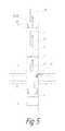
- FIG. 1is a side elevation view of the present system in a well hole.
- FIG. 2is a flow diagram during hydraulic fracturing.
- FIG. 3is a flow diagram during the first method of removing residual fracking fluid and proppant.
- FIG. 4is a flow diagram during the second method of removing residual fracking fluid and proppant. It shows cleaning of the section between the packers by the jet pump.
- FIG. 5is a flow diagram showing removal of fracking fluid above a top packer prior to either of the first or second methods of removing fracking fluid between the top and bottom packers.
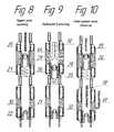
- FIGS. 6 to 10are sequential sectional views showing the operation of the hydraulic fracturing port and the circulation port prior to, during and following fracking, according to an aspect of the preferred method.
- FIG. 11is a sectional side elevation view of the jet pump casing.
- FIG. 12is a sectional side elevation view of the circulation valve.
- FIG. 13is a sectional side elevation view of the top packer prior to deployment.
- FIG. 14is a sectional side elevation view of the hydraulic fracturing port prior to fracking.
- FIG. 15is a sectional side elevation view of the circulation port and the bottom packer prior to deployment of the bottom packer.
- FIG. 16is a sectional side elevation view of the top packer after deployment.
- FIG. 17is a sectional side elevation view of circulation port and the bottom packer after deployment of the bottom packer.
- FIG. 18is a sectional side elevation view of the top packer after deployment showing a fixing ram preventing the assembly from longitudinal movement in the well during the fracking. (The fixing ram protrudes out of the packer under the high pressures created in the tubing string).
- FIG. 19is a sectional side elevation view of the hydraulic fracturing port during fracking.
- FIG. 21is a sectional elevation view of the circulation valve being opened (such that cleaning above the circulation valve can be performed).
- FIG. 23is a sectional elevation view of the circulation valve after it has been closed.
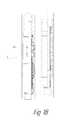
- FIG. 25is a sectional side elevation view of circulation port and the bottom packer after fracking has been performed.
- FIG. 26is a sectional view of the jet pump, showing the operation of the jet pump.
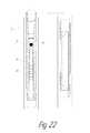
- FIG. 27is a sectional side elevation view of the top packer after deployment (such that the interval between the top and bottom packers is isolated).
- FIG. 1is a side elevation view of the present system in a well hole, as follows.
- a hydraulic fracturing systemis placed into well hole 7 .
- Well hole 7has a bottom end 9 .
- Hydraulic fracturing systemcomprises: a longitudinally extending assembly 10 ; a bottom packer 6 on longitudinally extending assembly 10 ; a circulation port 5 positioned above bottom packer 6 ; a hydraulic fracturing port 4 positioned above circulation port 5 ; a top packer 3 positioned above hydraulic fracturing port 4 ; a circulation valve 2 positioned above top packer 3 ; and an insert jet pump 1 positioned above circulation valve 2 .
- frackingis performed by first sealing packers 3 and 6 against the side walls of well hole 7 (thereby sealing a section of well between packers 3 and 6 ).
- fracking fluid FFis injected down through assembly 10 and out of hydraulic fracturing port 4 . This high powered injection of fracking fluid FF into the surrounding rock will release gas and/or oil trapped in the rock such that the gas/oil can be captured at the surface.
- cleaning fluids CFare injected down into well hole 7 .
- Circulation valve 2remains closed, but top packer 3 is unsealed through opening a bypass valve to let CF go under top packer 3 thus equalizing pressures above and under top packer 3 and after that lifting the tubing string up to remove weight off top packer 3 thus unsealing it.
- Circulation port 5will also be opened.
- the tubing section above top packer 3can be cleaned by: opening the circulation valve above the top packer, and pressurizing the well hole, thereby pushing cleaning fluid into the tubing through the circulation valve above the top packer, thereby pushing remaining fracking fluid with proppant sitting inside the tubing above the top packer back up through the assembly and out of the well hole.
- jet pump 1can be used for removing residual unstable proppant and performing completion of the well.
- top packer 3is again activated; insert jet pump 1 is dropped to be placed on a special seat positioned on the hydraulic fracturing assembly 10 above top packer 3 ; and then suction is created with jet pump 1 , thereby removing remaining unstable proppant sitting in the well between the top and bottom packers 3 and 6 .
- cleaning fluids CFare also injected down into well hole 7 .
- primarily circulation valve 2will be opened such that cleaning fluid flow will be directed through it into the tubing and then upwardly back up to the surface. (Fracturing port 4 will remain closed at this time).
- frackingis performed as follows. First, assembly 10 is placed in position within well hole 7 . Next, top and bottom packers 3 and 6 are activated such that they expand outwardly and seal a section 8 of well hole 7 therebetween.
- FIG. 4illustrates a step of cleaning through circulation valve 2 that can be included into either the first or second methods of removing fracking fluid from the well bore after hydraulic fracturing and must if necessary be performed prior to steps of cleaning section between packers 3 and 6 .
- the following stepscan be performed prior to opening the bypass valve in the top packer 3 (in the first method), or prior to inserting the jet pump 1 into the assembly (in the second method, FIG. 5 ); the following steps can be performed.
- circulation valve 2is opened.
- the well holeis pressurized, thereby pushing fluid into the circulation valve 2 (which sits above top packer 3 ), thereby pushing remaining fracking fluid with proppant sitting inside tubing above top packer 3 back up through the assembly and out of the well hole.
- the region of tubing above the top packer 3can be cleaned prior to cleaning the region between packers 3 and 6 (using either of the two above described methods).
- hydraulic fracturing port 4 and circulation port 5are both initially closed.
- a small ball 21is dropped down a center bore of assembly 10 , resting in seat 22 .
- downward pressure in the center bore of assembly 10will push ball 21 downwards, thereby pushing seat 22 downwards, thereby opening external holes 30 .
- a second (larger) ball 25is dropped down a center bore of assembly 10 , resting on seat 26 (which sits on spring 27 ), thereby, when pressurized, pushing seat 26 downwards, opening external holes 29 .
- the fracturing fluid (and proppant therein)is injected from above such that it passes out of holes 29 and into the surrounding rock to release gasses/oil G/O trapped therein. (Thus fracking is carried out at the step shown in FIG. 9 ).
- FIG. 10also illustrates the situation where the jet pump 1 instead is used to create a suction force in assembly 10 such that the residual fracking fluid FF sitting on top of bottom packer 6 will instead be vacuumed up through external holes 30 in circulation port 5 , and then drawn out at the ground surface.
- spring 27will cause seat 26 to rise up thereby sealing holes 29 .
- the residual fracking fluid FF passing upwardswill return ball 25 to the ground surface.
- FIG. 14is a sectional side elevation view of hydraulic fracturing port 4 prior to fracking.
- FIG. 19is a sectional side elevation view of hydraulic fracturing port 4 after ball 25 has been dropped therein moving seat 26 downwards, depressing spring 27 .
- Frackingis carried out in the step illustrated in FIG. 19 with fracking fluid FF passing out of external holes 29 .
- fracking fluidwill no longer be pushed down through the center of the device, and spring 27 will rise, sealing external holes 29 with seat 26 .
- FIG. 20illustrates a sectional side elevation view after ball 21 has been dropped into seat 22 , pushing seat 22 downwardly, thereby opening external holes 30 .
- the seatis fixed in the position by a collet 23 catching on a ledge 24 .
- FIG. 25shows residual fracking fluid FF being removed (by either of the two preferred methods described herein). Specifically, FIG. 25 shows the second method where the passage of cleaning fluid into jet pump 1 suctions fracking fluid with proppant from the wellbore interval between top packer 3 and bottom packer 6 to the ground surface.
- FIG. 13is a sectional side elevation view of top packer 3 prior to deployment.
- FIG. 16is a sectional side elevation view of top packer 3 after deployment. As seen in FIG. 16 , further lowering the fracturing assembly causes top packer 3 's movable casing 11 slide along and up its mandrel 12 forcing its seals 13 to expand. Thus top packer 3 becomes fixed at its location.
- FIG. 18is a sectional side elevation view of top packer 3 after deployment showing fixing rams 28 preventing the assembly from longitudinal movement in the well during the fracking. Fixing rams 28 go out of the packer under high pressure created in the tubing.
- bypass seal 14moves from the position shown on FIG. 16 to the position shown on FIG. 24 (the same as on FIG. 13 ).
- a bypass channel 44is open to let fluid go from the interval above top packer 3 to the interval between the packers.
- FIG. 24shows the next step of top packer 3 unsealing where the assembly is raised further to slack off weight on top packer 3 .
- top packer 3returns to its initial position (like in FIG. 13 ), thus giving the well bore cleaning fluid the way to the circulation port 5 .
- FIG. 27shows the expanded top packer position during the operation of jet pump 1 . Specifically, assembly 10 is lowered and its weight widens top packer seals 13 again. The interval between the top and bottom packers is thus isolated.
- FIG. 12is a sectional side elevation view of circulation valve 2 .
- FIG. 21is a sectional elevation view of circulation valve 2 being opened.
- cleaning fluid CFis pressurized into the well bore.
- This cleaning fluid CFenters circulation valve chamber 32 through small ports 31 in the valve's casing.
- the fluidthen moves sleeve 33 upwards to make ports 34 , 35 , 36 match up and thereby open a passage for the cleaning fluid from well bore 7 to enter into circulation valve 2 and rise up to the surface.
- the result of this fluid circulationwill be to displace any residual fracking fluid sitting in the tubing above the circulation valve by incoming cleaning fluid and to push it up through assembly 10 such that it can be recovered at the ground surface.
- FIGS. 11 and 26illustrate operation of jet pump 1 .
- FIG. 11is a sectional side elevation view of jet pump 1 casing seat. Jet pump 1 may preferably be inserted into the longitudinally extending assembly after the hydraulic fracturing has been completed and preliminary cleaning is performed through circulation valve 2 of the tubing interval above top packer 3 .
- FIG. 26is a sectional view of jet pump 1 , showing the operation of the jet pump, as follows.
- the jet pump insert module 37is dropped down from the surface to rest on a movable sleeve 38 blocking the jet pump casing inlet passage 39 .
- Pressureis created in the tubings to push the insert module 37 on a sleeve 38 downwardly to open the jet pump casing inlet passage 39 .
- FIG. 26shows the operation of the jet pump where the working fluid CF goes through the inlet passage 39 into a nozzle 40 , and then through a chamber 41 gets into the venturi chamber 42 , and passing ports 43 gets into the tubing and goes upward to the surface.
- the high-speed stream within chamber 41creates a low pressure.
- the working fluid CF and the fracking fluid FFmix within the venturi chamber 42 .
- FIG. 6.1shows the operation of the jet pump where the working fluid (stream A) goes through the inlet passage 39 into a nozzle 40 , and then through a chamber 41 gets into the venturi chamber 42 , and passing ports 43 gets into the tubing and goes upward to the surface.
- the high-speed stream within chamber 41creates a low pressure.
Landscapes
- Engineering & Computer Science (AREA)
- Mining & Mineral Resources (AREA)
- Life Sciences & Earth Sciences (AREA)
- Geology (AREA)
- Physics & Mathematics (AREA)
- Fluid Mechanics (AREA)
- Environmental & Geological Engineering (AREA)
- General Life Sciences & Earth Sciences (AREA)
- Geochemistry & Mineralogy (AREA)
- Mechanical Engineering (AREA)
- General Engineering & Computer Science (AREA)
- General Physics & Mathematics (AREA)
- Check Valves (AREA)
- Consolidation Of Soil By Introduction Of Solidifying Substances Into Soil (AREA)
Abstract
Description
Claims (14)
Priority Applications (2)
| Application Number | Priority Date | Filing Date | Title |
|---|---|---|---|
| US15/686,660US10450813B2 (en) | 2017-08-25 | 2017-08-25 | Hydraulic fraction down-hole system with circulation port and jet pump for removal of residual fracking fluid |
| RU2018131277ARU2709892C1 (en) | 2017-08-25 | 2018-08-25 | System of downhole equipment for hydraulic fracturing and method of conducting hydraulic fracturing (versions) |
Applications Claiming Priority (1)
| Application Number | Priority Date | Filing Date | Title |
|---|---|---|---|
| US15/686,660US10450813B2 (en) | 2017-08-25 | 2017-08-25 | Hydraulic fraction down-hole system with circulation port and jet pump for removal of residual fracking fluid |
Publications (2)
| Publication Number | Publication Date |
|---|---|
| US20190063171A1 US20190063171A1 (en) | 2019-02-28 |
| US10450813B2true US10450813B2 (en) | 2019-10-22 |
Family
ID=65437242
Family Applications (1)
| Application Number | Title | Priority Date | Filing Date |
|---|---|---|---|
| US15/686,660ActiveUS10450813B2 (en) | 2017-08-25 | 2017-08-25 | Hydraulic fraction down-hole system with circulation port and jet pump for removal of residual fracking fluid |
Country Status (2)
| Country | Link |
|---|---|
| US (1) | US10450813B2 (en) |
| RU (1) | RU2709892C1 (en) |
Families Citing this family (5)
| Publication number | Priority date | Publication date | Assignee | Title |
|---|---|---|---|---|
| RU2759247C1 (en)* | 2020-05-12 | 2021-11-11 | Акционерное общество "Самотлорнефтегаз" | Method for conducting multi-stage hydraulic fracturing in conditions of thin bridges |
| RU2747495C1 (en)* | 2020-08-21 | 2021-05-05 | Салават Анатольевич Кузяев | Device and method for selective treatment of a productive formation |
| RU2750792C1 (en)* | 2020-10-21 | 2021-07-02 | Николай Маратович Шамсутдинов | Method for conducting hydraulic fracturing in inclined-directional oil well operating single product reservoir |
| RU2752371C1 (en)* | 2020-10-24 | 2021-07-26 | Николай Маратович Шамсутдинов | Method for conducting hydraulic fracture treatment in inclined-directed oil-producing well operating two productive formations |
| CN116122773B (en)* | 2022-11-25 | 2023-10-17 | 阜宁县宏达石化机械有限公司 | Single-double-tube combined jet pipe column |
Citations (98)
| Publication number | Priority date | Publication date | Assignee | Title |
|---|---|---|---|---|
| US4183722A (en) | 1977-06-06 | 1980-01-15 | Roeder George K | Downhole jet pumps |
| US4293283A (en) | 1977-06-06 | 1981-10-06 | Roeder George K | Jet with variable throat areas using a deflector |
| US4504195A (en) | 1981-06-30 | 1985-03-12 | Armco Inc. | Jet pump for oil wells |
| US4527836A (en) | 1983-04-29 | 1985-07-09 | Mobil Oil Corporation | Deep well process for slurry pick-up in hydraulic borehole mining devices |
| US4653586A (en) | 1985-12-20 | 1987-03-31 | Atlantic Richfield Company | Method and apparatus for controlling sand accumulation in a producing wellbore |
| US4658893A (en) | 1986-05-16 | 1987-04-21 | Black John B | Jet pump with reverse flow removal of injection nozzle |
| US4664603A (en) | 1984-07-31 | 1987-05-12 | Double R Petroleum Recovery, Inc. | Petroleum recovery jet pump pumping system |
| US4726420A (en) | 1986-02-27 | 1988-02-23 | Petro-Lift Development Corp. | Oil well pumping system |
| US4744730A (en) | 1986-03-27 | 1988-05-17 | Roeder George K | Downhole jet pump with multiple nozzles axially aligned with venturi for producing fluid from boreholes |
| US4878539A (en) | 1988-08-02 | 1989-11-07 | Anders Energy Corporation | Method and system for maintaining and producing horizontal well bores |
| US4988389A (en) | 1987-10-02 | 1991-01-29 | Adamache Ion Ionel | Exploitation method for reservoirs containing hydrogen sulphide |
| US5000264A (en) | 1990-02-26 | 1991-03-19 | Marathon Oil Company | Method and means for introducing treatment fluid into a subterranean formation |
| US5055002A (en) | 1989-05-12 | 1991-10-08 | Roeder George K | Downhole pump with retrievable nozzle assembly |
| EP0590805A1 (en) | 1992-09-29 | 1994-04-06 | Halliburton Company | Well completion by fracturing |
| WO1995029322A1 (en) | 1994-04-27 | 1995-11-02 | Valery Petrovich Dyblenko | Method of working the bottom-hole zone of a seam |
| US5494103A (en) | 1992-09-29 | 1996-02-27 | Halliburton Company | Well jetting apparatus |
| US5879057A (en) | 1996-11-12 | 1999-03-09 | Amvest Corporation | Horizontal remote mining system, and method |
| US6446727B1 (en) | 1998-11-12 | 2002-09-10 | Sclumberger Technology Corporation | Process for hydraulically fracturing oil and gas wells |
| US6520255B2 (en) | 2000-02-15 | 2003-02-18 | Exxonmobil Upstream Research Company | Method and apparatus for stimulation of multiple formation intervals |
| WO2003027431A2 (en) | 2001-09-26 | 2003-04-03 | Cooke Claude E Jr | Method and materials for hydraulic fracturing of wells |
| US6547011B2 (en) | 1998-11-02 | 2003-04-15 | Halliburton Energy Services, Inc. | Method and apparatus for controlling fluid flow within wellbore with selectively set and unset packer assembly |
| US6662874B2 (en) | 2001-09-28 | 2003-12-16 | Halliburton Energy Services, Inc. | System and method for fracturing a subterranean well formation for improving hydrocarbon production |
| US6712148B2 (en) | 2002-06-04 | 2004-03-30 | Halliburton Energy Services, Inc. | Junction isolation apparatus and methods for use in multilateral well treatment operations |
| US20040071557A1 (en) | 2001-04-05 | 2004-04-15 | Khomynets Zinoviy Dmitrievich | Well jet device |
| US6899188B2 (en) | 2003-03-26 | 2005-05-31 | Sunstone Corporation | Down hole drilling assembly with concentric casing actuated jet pump |
| US20050133226A1 (en) | 2003-12-18 | 2005-06-23 | Lehman Lyle V. | Modular hydrojetting tool |
| US20050155773A1 (en) | 2004-01-21 | 2005-07-21 | Schlumberger Technology Corporation | System and Method to Deploy and Expand Tubular Components Deployed Through Tubing |
| US20060196674A1 (en) | 2003-08-26 | 2006-09-07 | Weatherford/Lamb, Inc. | Artificial lift with additional gas assist |
| US20060213670A1 (en) | 2003-02-24 | 2006-09-28 | Bj Services Company | Bi-directional ball seat system and method |
| US20070000666A1 (en) | 2004-12-23 | 2007-01-04 | Charles Vozniak | Method and system for fracturing subterranean formations with a proppant and dry gas |
| US7159660B2 (en) | 2004-05-28 | 2007-01-09 | Halliburton Energy Services, Inc. | Hydrajet perforation and fracturing tool |
| WO2007050530A1 (en) | 2005-10-26 | 2007-05-03 | Baker Hugues Incorporated | Fracking multiple casing exit laterals |
| US20070158073A1 (en) | 2005-10-26 | 2007-07-12 | Green Rickey J | Fracking multiple casing exit laterals |
| WO2007126331A1 (en) | 2006-05-02 | 2007-11-08 | Zinoviy Dmitrievich Khomynets | Method for operating a jet device for developing and operating oil- and-gas wells |
| WO2007149008A1 (en) | 2006-06-16 | 2007-12-27 | Zinoviy Dmitrievich Khomynets | Method for operating a well jet device at a hydraulic fracturing of multilayer hydrocarbon reservoirs |
| US7337844B2 (en) | 2006-05-09 | 2008-03-04 | Halliburton Energy Services, Inc. | Perforating and fracturing |
| US20080115934A1 (en) | 2006-11-20 | 2008-05-22 | Pettinato Miguel H | Multi-Zone Formation Evaluation Systems and Methods |
| US7401651B2 (en) | 2005-09-27 | 2008-07-22 | Smith International, Inc. | Wellbore fluid saver assembly |
| US20080210424A1 (en) | 2007-03-02 | 2008-09-04 | Trican Well Service Ltd. | Apparatus and Method of Fracturing |
| US20080264627A1 (en) | 2007-04-30 | 2008-10-30 | Smith International, Inc. | Permanent anchoring device |
| US20080314595A1 (en) | 2006-03-22 | 2008-12-25 | Zinoviy Dmitrievich Khomynets | Well Jet Device and the Operating Method Thereof |
| US20090025923A1 (en) | 2007-07-23 | 2009-01-29 | Schlumberger Technology Corporation | Technique and system for completing a well |
| US7516797B2 (en) | 2004-12-20 | 2009-04-14 | Zinoviy Dmitrievich Khomynets | Method for operating a well jet device in the conditions of a formation hydraulic fracturing |
| US7549478B2 (en) | 2005-11-25 | 2009-06-23 | Zinoviy Dmitrievich Khomynets | Well jet device and the operating method thereof |
| US20090294137A1 (en) | 2008-05-29 | 2009-12-03 | Schlumberger Technology Corporation | Wellbore packer |
| US7735568B2 (en) | 2006-03-29 | 2010-06-15 | Schlumberger Technology Corporation | Packer cup systems for use inside a wellbore |
| US20100157737A1 (en) | 2007-12-21 | 2010-06-24 | Schlumberger Technology Corporation | Microhydraulic fracturing with downhole acoustic measurement |
| US7757762B2 (en) | 2007-10-02 | 2010-07-20 | Baker Hughes Incorporated | Downhole tools having screens for insertion into gravel disposed in wellbores and methods of installing same |
| US20100243256A1 (en) | 2007-10-10 | 2010-09-30 | Zinoviy Dmitrievich Khomynets | Bore-hole jet device for formation hydraulic fracturing and horizontal well examination and a method for the operation thereof |
| WO2010148494A1 (en) | 2009-06-22 | 2010-12-29 | Trican Well Service Ltd. | Apparatus and method for stimulating subterranean formations |
| US20110000661A1 (en) | 2007-07-18 | 2011-01-06 | Zinoviy Dmitrievich Khomynets | Well jet device |
| US20110139456A1 (en) | 2009-07-20 | 2011-06-16 | Conocophillips Company | Controlled Fracture Initiation Stress Packer |
| US20110203809A1 (en) | 2010-02-09 | 2011-08-25 | Knobloch Jr Benton T | Wellbore bypass tool and related methods of use |
| US20110214498A1 (en) | 2010-03-02 | 2011-09-08 | Fadhel Rezgui | Flow restriction insert for differential pressure measurement |
| US20110247816A1 (en) | 2008-12-10 | 2011-10-13 | Carter Jr Ernest E | Method and Apparatus for Increasing Well Productivity |
| US20120043080A1 (en) | 2010-08-18 | 2012-02-23 | Schlumberger Technology Corporation | Methods for downhole sampling of tight formations |
| US20120134853A1 (en) | 2009-06-09 | 2012-05-31 | Zinoviy Dmitrievich Khomynets | Down-hole jet equipment for logging and development of horizontal wells |
| US8220547B2 (en) | 2009-07-31 | 2012-07-17 | Schlumberger Technology Corporation | Method and apparatus for multilateral multistage stimulation of a well |
| US8490704B2 (en) | 2009-12-04 | 2013-07-23 | Schlumberger Technology | Technique of fracturing with selective stream injection |
| US8544540B2 (en) | 2008-06-25 | 2013-10-01 | Zinoviy Dmitrievich Khomynets | Well jet device for logging and developing horizontal wells with abnormally low formation pressure |
| US8561687B2 (en) | 2006-01-06 | 2013-10-22 | Trican Well Service Ltd. | Pressure containment devices and methods of using same |
| US20130284026A1 (en) | 2012-03-21 | 2013-10-31 | Horizontal Rentals, Inc. | Oil skimming apparatus and method for using same |
| WO2013184301A1 (en) | 2012-06-04 | 2013-12-12 | Schlumberger Canada Limited | Apparatus configuration downhole |
| US8622124B2 (en) | 2007-04-30 | 2014-01-07 | Schlumberger Technology Corporation | Well treatment using electric submersible pumping system |
| US8631877B2 (en) | 2008-06-06 | 2014-01-21 | Schlumberger Technology Corporation | Apparatus and methods for inflow control |
| US20140076546A1 (en) | 2012-09-19 | 2014-03-20 | Schlumberger Technology Corporation | Single Trip Multi-Zone Drill Stem Test System |
| US20140124199A1 (en) | 2011-06-10 | 2014-05-08 | Meta Downhole Limited | Tubular Assembly and Method of Deploying A Downhole Device Using A Tubular Assembly |
| WO2014098941A1 (en) | 2012-12-18 | 2014-06-26 | Schlumberger Canada Limited | System and method for determining mechanical properties of a formation |
| WO2014153314A1 (en) | 2013-03-18 | 2014-09-25 | Schlumberger Canada Limited | Sleeve valve |
| US8915300B2 (en) | 2011-09-01 | 2014-12-23 | Team Oil Tools, Lp | Valve for hydraulic fracturing through cement outside casing |
| US20140374091A1 (en) | 2013-06-20 | 2014-12-25 | Schlumberger Technology Corporation | Electromagnetic Imaging Of Proppant In Induced Fractures |
| US20150000911A1 (en) | 2010-06-18 | 2015-01-01 | Schlumberger Technology Corporation | Method of isolating a wellbore with solid acid for fracturing |
| US20150041130A1 (en) | 2013-08-07 | 2015-02-12 | Schlumberger Technology Corporation | System and Method for Actuating Downhole Packers |
| US8978773B2 (en) | 2013-03-13 | 2015-03-17 | Halliburton Energy Services, Inc. | Sliding sleeve bypass valve for well treatment |
| US20150083404A1 (en) | 2013-09-23 | 2015-03-26 | Schlumberger Technology Corporation | Determining proppant and fluid distribution |
| US9016119B2 (en) | 2012-06-27 | 2015-04-28 | Schlumberger Technology Corporation | Pore pressure measurement in low-permeability and impermeable materials |
| US20150129203A1 (en) | 2008-08-20 | 2015-05-14 | Foro Energy, Inc. | High power laser hydraulic fracturing, stimulation, tools systems and methods |
| US9038452B2 (en) | 2012-07-11 | 2015-05-26 | Schlumberger Technology Corporation | Systems and methods for measuring forces acting on a downhole tool |
| US20150167652A1 (en) | 2013-12-18 | 2015-06-18 | General Electric Company | Submersible pumping system and method |
| US20150167442A1 (en) | 2013-12-18 | 2015-06-18 | Schlumberger Technology Corporation | Formation Fracturing And Sampling Methods |
| US9062544B2 (en) | 2011-11-16 | 2015-06-23 | Schlumberger Technology Corporation | Formation fracturing |
| US20150176384A1 (en) | 2013-12-24 | 2015-06-25 | Baker Hughes Incorporated | One Trip Multi-interval Plugging, Perforating and Fracking Method |
| US20150176386A1 (en) | 2013-12-24 | 2015-06-25 | Baker Hughes Incorporated | Using a Combination of a Perforating Gun with an Inflatable to Complete Multiple Zones in a Single Trip |
| US9074470B2 (en) | 2010-12-27 | 2015-07-07 | Seven Generations Energy Ltd. | Methods for drilling and stimulating subterranean formations for recovering hydrocarbon and natural gas resources |
| US20150285023A1 (en) | 2012-11-12 | 2015-10-08 | Schlumberger Technology Corporation | System, method, and apparatus for multi-stage completion |
| US20150308434A1 (en)* | 2014-04-24 | 2015-10-29 | Pumptek Asia Ltd., Dba Pumptek, Llc | Pumping system |
| US9206659B2 (en) | 2010-02-04 | 2015-12-08 | Trican Well Service Ltd. | Applications of smart fluids in well service operations |
| US20160024884A1 (en) | 2014-07-22 | 2016-01-28 | Toby Scott Baudoin | Mechanically Activated Bypass Valve Apparatus and Method |
| US20160045888A1 (en) | 2011-03-30 | 2016-02-18 | Altmerge, Llc | Pulse Jet System and Method |
| WO2016028513A1 (en) | 2014-08-22 | 2016-02-25 | Schlumberger Canada Limited | Hydraulic fracturing while drilling and/or tripping |
| US20160084044A1 (en) | 2014-09-18 | 2016-03-24 | Schlumberger Technology Corporation | Low pressure direct proppant injection |
| US9309731B2 (en) | 2009-10-06 | 2016-04-12 | Schlumberger Technology Corporation | Formation testing planning and monitoring |
| US9375761B1 (en) | 2012-06-08 | 2016-06-28 | Walker-Dawson Interests, Inc. | Methods for modifying non-standard frac sand to sand with fracking properties |
| US9382793B2 (en) | 2012-12-20 | 2016-07-05 | Schlumberger Technology Corporation | Probe packer including rigid intermediate containment ring |
| WO2016144634A1 (en) | 2015-03-10 | 2016-09-15 | Schlumberger Technology Corporation | Fracturing while tripping |
| US9458686B2 (en) | 2011-08-08 | 2016-10-04 | Trican Well Service Ltd. | Fracturing tool anchor |
| US20180094508A1 (en)* | 2016-09-30 | 2018-04-05 | Baker Hughes Incorporated | Frac and gravel packing system having return path and method |
| US20180283132A1 (en)* | 2015-12-14 | 2018-10-04 | Halliburton Energy Services, Inc. | One Trip Completion Assembly System and Method |
Family Cites Families (6)
| Publication number | Priority date | Publication date | Assignee | Title |
|---|---|---|---|---|
| RU2179623C2 (en)* | 1999-12-14 | 2002-02-20 | Общество с ограниченной ответственностью "Кубаньгазпром" | Circulation valve |
| US8528641B2 (en)* | 2009-09-03 | 2013-09-10 | Baker Hughes Incorporated | Fracturing and gravel packing tool with anti-swabbing feature |
| US9920600B2 (en)* | 2011-06-10 | 2018-03-20 | Schlumberger Technology Corporation | Multi-stage downhole hydraulic stimulation assembly |
| RU142704U1 (en)* | 2012-10-25 | 2014-06-27 | Пассербай Инк | Borehole layout for conducting selective hydraulic fracturing (OPTIONS) |
| WO2014094135A1 (en)* | 2012-12-21 | 2014-06-26 | Resource Well Completion Technologies Inc. | Multi-stage well isolation |
| US10221648B2 (en)* | 2014-01-24 | 2019-03-05 | Completions Research Ag | Multistage high pressure fracturing system with counting system |
- 2017
- 2017-08-25USUS15/686,660patent/US10450813B2/enactiveActive
- 2018
- 2018-08-25RURU2018131277Apatent/RU2709892C1/enactiveIP Right Revival
Patent Citations (104)
| Publication number | Priority date | Publication date | Assignee | Title |
|---|---|---|---|---|
| US4293283A (en) | 1977-06-06 | 1981-10-06 | Roeder George K | Jet with variable throat areas using a deflector |
| US4183722A (en) | 1977-06-06 | 1980-01-15 | Roeder George K | Downhole jet pumps |
| US4504195A (en) | 1981-06-30 | 1985-03-12 | Armco Inc. | Jet pump for oil wells |
| US4527836A (en) | 1983-04-29 | 1985-07-09 | Mobil Oil Corporation | Deep well process for slurry pick-up in hydraulic borehole mining devices |
| US4664603A (en) | 1984-07-31 | 1987-05-12 | Double R Petroleum Recovery, Inc. | Petroleum recovery jet pump pumping system |
| US4653586A (en) | 1985-12-20 | 1987-03-31 | Atlantic Richfield Company | Method and apparatus for controlling sand accumulation in a producing wellbore |
| US4726420A (en) | 1986-02-27 | 1988-02-23 | Petro-Lift Development Corp. | Oil well pumping system |
| US4744730A (en) | 1986-03-27 | 1988-05-17 | Roeder George K | Downhole jet pump with multiple nozzles axially aligned with venturi for producing fluid from boreholes |
| US4658893A (en) | 1986-05-16 | 1987-04-21 | Black John B | Jet pump with reverse flow removal of injection nozzle |
| US4988389A (en) | 1987-10-02 | 1991-01-29 | Adamache Ion Ionel | Exploitation method for reservoirs containing hydrogen sulphide |
| US4878539A (en) | 1988-08-02 | 1989-11-07 | Anders Energy Corporation | Method and system for maintaining and producing horizontal well bores |
| US5055002A (en) | 1989-05-12 | 1991-10-08 | Roeder George K | Downhole pump with retrievable nozzle assembly |
| US5000264A (en) | 1990-02-26 | 1991-03-19 | Marathon Oil Company | Method and means for introducing treatment fluid into a subterranean formation |
| EP0590805A1 (en) | 1992-09-29 | 1994-04-06 | Halliburton Company | Well completion by fracturing |
| US5494103A (en) | 1992-09-29 | 1996-02-27 | Halliburton Company | Well jetting apparatus |
| WO1995029322A1 (en) | 1994-04-27 | 1995-11-02 | Valery Petrovich Dyblenko | Method of working the bottom-hole zone of a seam |
| US5879057A (en) | 1996-11-12 | 1999-03-09 | Amvest Corporation | Horizontal remote mining system, and method |
| US6547011B2 (en) | 1998-11-02 | 2003-04-15 | Halliburton Energy Services, Inc. | Method and apparatus for controlling fluid flow within wellbore with selectively set and unset packer assembly |
| US6446727B1 (en) | 1998-11-12 | 2002-09-10 | Sclumberger Technology Corporation | Process for hydraulically fracturing oil and gas wells |
| US6520255B2 (en) | 2000-02-15 | 2003-02-18 | Exxonmobil Upstream Research Company | Method and apparatus for stimulation of multiple formation intervals |
| US20040071557A1 (en) | 2001-04-05 | 2004-04-15 | Khomynets Zinoviy Dmitrievich | Well jet device |
| WO2003027431A2 (en) | 2001-09-26 | 2003-04-03 | Cooke Claude E Jr | Method and materials for hydraulic fracturing of wells |
| US6662874B2 (en) | 2001-09-28 | 2003-12-16 | Halliburton Energy Services, Inc. | System and method for fracturing a subterranean well formation for improving hydrocarbon production |
| US6712148B2 (en) | 2002-06-04 | 2004-03-30 | Halliburton Energy Services, Inc. | Junction isolation apparatus and methods for use in multilateral well treatment operations |
| US20060213670A1 (en) | 2003-02-24 | 2006-09-28 | Bj Services Company | Bi-directional ball seat system and method |
| US6899188B2 (en) | 2003-03-26 | 2005-05-31 | Sunstone Corporation | Down hole drilling assembly with concentric casing actuated jet pump |
| US20060196674A1 (en) | 2003-08-26 | 2006-09-07 | Weatherford/Lamb, Inc. | Artificial lift with additional gas assist |
| US20050133226A1 (en) | 2003-12-18 | 2005-06-23 | Lehman Lyle V. | Modular hydrojetting tool |
| US20050155773A1 (en) | 2004-01-21 | 2005-07-21 | Schlumberger Technology Corporation | System and Method to Deploy and Expand Tubular Components Deployed Through Tubing |
| US7159660B2 (en) | 2004-05-28 | 2007-01-09 | Halliburton Energy Services, Inc. | Hydrajet perforation and fracturing tool |
| US7516797B2 (en) | 2004-12-20 | 2009-04-14 | Zinoviy Dmitrievich Khomynets | Method for operating a well jet device in the conditions of a formation hydraulic fracturing |
| US20070000666A1 (en) | 2004-12-23 | 2007-01-04 | Charles Vozniak | Method and system for fracturing subterranean formations with a proppant and dry gas |
| US7401651B2 (en) | 2005-09-27 | 2008-07-22 | Smith International, Inc. | Wellbore fluid saver assembly |
| US20070158073A1 (en) | 2005-10-26 | 2007-07-12 | Green Rickey J | Fracking multiple casing exit laterals |
| WO2007050530A1 (en) | 2005-10-26 | 2007-05-03 | Baker Hugues Incorporated | Fracking multiple casing exit laterals |
| US7549478B2 (en) | 2005-11-25 | 2009-06-23 | Zinoviy Dmitrievich Khomynets | Well jet device and the operating method thereof |
| US8561687B2 (en) | 2006-01-06 | 2013-10-22 | Trican Well Service Ltd. | Pressure containment devices and methods of using same |
| US20080314595A1 (en) | 2006-03-22 | 2008-12-25 | Zinoviy Dmitrievich Khomynets | Well Jet Device and the Operating Method Thereof |
| US7735568B2 (en) | 2006-03-29 | 2010-06-15 | Schlumberger Technology Corporation | Packer cup systems for use inside a wellbore |
| WO2007126331A1 (en) | 2006-05-02 | 2007-11-08 | Zinoviy Dmitrievich Khomynets | Method for operating a jet device for developing and operating oil- and-gas wells |
| US7337844B2 (en) | 2006-05-09 | 2008-03-04 | Halliburton Energy Services, Inc. | Perforating and fracturing |
| WO2007149008A1 (en) | 2006-06-16 | 2007-12-27 | Zinoviy Dmitrievich Khomynets | Method for operating a well jet device at a hydraulic fracturing of multilayer hydrocarbon reservoirs |
| US20080115934A1 (en) | 2006-11-20 | 2008-05-22 | Pettinato Miguel H | Multi-Zone Formation Evaluation Systems and Methods |
| US8141638B2 (en) | 2007-03-02 | 2012-03-27 | Trican Well Services Ltd. | Fracturing method and apparatus utilizing gelled isolation fluid |
| US20080210424A1 (en) | 2007-03-02 | 2008-09-04 | Trican Well Service Ltd. | Apparatus and Method of Fracturing |
| US8622124B2 (en) | 2007-04-30 | 2014-01-07 | Schlumberger Technology Corporation | Well treatment using electric submersible pumping system |
| US20080264627A1 (en) | 2007-04-30 | 2008-10-30 | Smith International, Inc. | Permanent anchoring device |
| US20110000661A1 (en) | 2007-07-18 | 2011-01-06 | Zinoviy Dmitrievich Khomynets | Well jet device |
| US20090025923A1 (en) | 2007-07-23 | 2009-01-29 | Schlumberger Technology Corporation | Technique and system for completing a well |
| US7757762B2 (en) | 2007-10-02 | 2010-07-20 | Baker Hughes Incorporated | Downhole tools having screens for insertion into gravel disposed in wellbores and methods of installing same |
| US20100243256A1 (en) | 2007-10-10 | 2010-09-30 | Zinoviy Dmitrievich Khomynets | Bore-hole jet device for formation hydraulic fracturing and horizontal well examination and a method for the operation thereof |
| US8397808B2 (en) | 2007-10-10 | 2013-03-19 | Zinoviy Dmitrievich Khomynets | Bore-hole jet device for formation hydraulic fracturing and horizontal well examination and a method for the operation thereof |
| US20100157737A1 (en) | 2007-12-21 | 2010-06-24 | Schlumberger Technology Corporation | Microhydraulic fracturing with downhole acoustic measurement |
| US20090294137A1 (en) | 2008-05-29 | 2009-12-03 | Schlumberger Technology Corporation | Wellbore packer |
| US8631877B2 (en) | 2008-06-06 | 2014-01-21 | Schlumberger Technology Corporation | Apparatus and methods for inflow control |
| US8544540B2 (en) | 2008-06-25 | 2013-10-01 | Zinoviy Dmitrievich Khomynets | Well jet device for logging and developing horizontal wells with abnormally low formation pressure |
| US20150129203A1 (en) | 2008-08-20 | 2015-05-14 | Foro Energy, Inc. | High power laser hydraulic fracturing, stimulation, tools systems and methods |
| US20110247816A1 (en) | 2008-12-10 | 2011-10-13 | Carter Jr Ernest E | Method and Apparatus for Increasing Well Productivity |
| US20120134853A1 (en) | 2009-06-09 | 2012-05-31 | Zinoviy Dmitrievich Khomynets | Down-hole jet equipment for logging and development of horizontal wells |
| WO2010148494A1 (en) | 2009-06-22 | 2010-12-29 | Trican Well Service Ltd. | Apparatus and method for stimulating subterranean formations |
| US20110139456A1 (en) | 2009-07-20 | 2011-06-16 | Conocophillips Company | Controlled Fracture Initiation Stress Packer |
| US8220547B2 (en) | 2009-07-31 | 2012-07-17 | Schlumberger Technology Corporation | Method and apparatus for multilateral multistage stimulation of a well |
| US9309731B2 (en) | 2009-10-06 | 2016-04-12 | Schlumberger Technology Corporation | Formation testing planning and monitoring |
| US8490704B2 (en) | 2009-12-04 | 2013-07-23 | Schlumberger Technology | Technique of fracturing with selective stream injection |
| US9206659B2 (en) | 2010-02-04 | 2015-12-08 | Trican Well Service Ltd. | Applications of smart fluids in well service operations |
| US20110203809A1 (en) | 2010-02-09 | 2011-08-25 | Knobloch Jr Benton T | Wellbore bypass tool and related methods of use |
| US20110214498A1 (en) | 2010-03-02 | 2011-09-08 | Fadhel Rezgui | Flow restriction insert for differential pressure measurement |
| US8061219B2 (en) | 2010-03-02 | 2011-11-22 | Schlumberger Technology Corporation | Flow restriction insert for differential pressure measurement |
| US20150000911A1 (en) | 2010-06-18 | 2015-01-01 | Schlumberger Technology Corporation | Method of isolating a wellbore with solid acid for fracturing |
| US20120043080A1 (en) | 2010-08-18 | 2012-02-23 | Schlumberger Technology Corporation | Methods for downhole sampling of tight formations |
| US9074470B2 (en) | 2010-12-27 | 2015-07-07 | Seven Generations Energy Ltd. | Methods for drilling and stimulating subterranean formations for recovering hydrocarbon and natural gas resources |
| US20160045888A1 (en) | 2011-03-30 | 2016-02-18 | Altmerge, Llc | Pulse Jet System and Method |
| US20140124199A1 (en) | 2011-06-10 | 2014-05-08 | Meta Downhole Limited | Tubular Assembly and Method of Deploying A Downhole Device Using A Tubular Assembly |
| US9458686B2 (en) | 2011-08-08 | 2016-10-04 | Trican Well Service Ltd. | Fracturing tool anchor |
| US8915300B2 (en) | 2011-09-01 | 2014-12-23 | Team Oil Tools, Lp | Valve for hydraulic fracturing through cement outside casing |
| US9062544B2 (en) | 2011-11-16 | 2015-06-23 | Schlumberger Technology Corporation | Formation fracturing |
| US20130284026A1 (en) | 2012-03-21 | 2013-10-31 | Horizontal Rentals, Inc. | Oil skimming apparatus and method for using same |
| US9341046B2 (en) | 2012-06-04 | 2016-05-17 | Schlumberger Technology Corporation | Apparatus configuration downhole |
| WO2013184301A1 (en) | 2012-06-04 | 2013-12-12 | Schlumberger Canada Limited | Apparatus configuration downhole |
| US9375761B1 (en) | 2012-06-08 | 2016-06-28 | Walker-Dawson Interests, Inc. | Methods for modifying non-standard frac sand to sand with fracking properties |
| US9016119B2 (en) | 2012-06-27 | 2015-04-28 | Schlumberger Technology Corporation | Pore pressure measurement in low-permeability and impermeable materials |
| US9038452B2 (en) | 2012-07-11 | 2015-05-26 | Schlumberger Technology Corporation | Systems and methods for measuring forces acting on a downhole tool |
| US20140076546A1 (en) | 2012-09-19 | 2014-03-20 | Schlumberger Technology Corporation | Single Trip Multi-Zone Drill Stem Test System |
| WO2014047228A1 (en) | 2012-09-19 | 2014-03-27 | Schlumberger Canada Limited | Single trip multi-zone drill stem test system |
| US20150285023A1 (en) | 2012-11-12 | 2015-10-08 | Schlumberger Technology Corporation | System, method, and apparatus for multi-stage completion |
| WO2014098941A1 (en) | 2012-12-18 | 2014-06-26 | Schlumberger Canada Limited | System and method for determining mechanical properties of a formation |
| US9309758B2 (en) | 2012-12-18 | 2016-04-12 | Schlumberger Technology Corporation | System and method for determining mechanical properties of a formation |
| US9382793B2 (en) | 2012-12-20 | 2016-07-05 | Schlumberger Technology Corporation | Probe packer including rigid intermediate containment ring |
| US8978773B2 (en) | 2013-03-13 | 2015-03-17 | Halliburton Energy Services, Inc. | Sliding sleeve bypass valve for well treatment |
| WO2014153314A1 (en) | 2013-03-18 | 2014-09-25 | Schlumberger Canada Limited | Sleeve valve |
| US20140374091A1 (en) | 2013-06-20 | 2014-12-25 | Schlumberger Technology Corporation | Electromagnetic Imaging Of Proppant In Induced Fractures |
| US20150041130A1 (en) | 2013-08-07 | 2015-02-12 | Schlumberger Technology Corporation | System and Method for Actuating Downhole Packers |
| US20150083404A1 (en) | 2013-09-23 | 2015-03-26 | Schlumberger Technology Corporation | Determining proppant and fluid distribution |
| US20150167652A1 (en) | 2013-12-18 | 2015-06-18 | General Electric Company | Submersible pumping system and method |
| US20150167442A1 (en) | 2013-12-18 | 2015-06-18 | Schlumberger Technology Corporation | Formation Fracturing And Sampling Methods |
| US20150176386A1 (en) | 2013-12-24 | 2015-06-25 | Baker Hughes Incorporated | Using a Combination of a Perforating Gun with an Inflatable to Complete Multiple Zones in a Single Trip |
| US20150176384A1 (en) | 2013-12-24 | 2015-06-25 | Baker Hughes Incorporated | One Trip Multi-interval Plugging, Perforating and Fracking Method |
| US20150308434A1 (en)* | 2014-04-24 | 2015-10-29 | Pumptek Asia Ltd., Dba Pumptek, Llc | Pumping system |
| US20160024884A1 (en) | 2014-07-22 | 2016-01-28 | Toby Scott Baudoin | Mechanically Activated Bypass Valve Apparatus and Method |
| WO2016028513A1 (en) | 2014-08-22 | 2016-02-25 | Schlumberger Canada Limited | Hydraulic fracturing while drilling and/or tripping |
| US20160084044A1 (en) | 2014-09-18 | 2016-03-24 | Schlumberger Technology Corporation | Low pressure direct proppant injection |
| WO2016144634A1 (en) | 2015-03-10 | 2016-09-15 | Schlumberger Technology Corporation | Fracturing while tripping |
| US20180283132A1 (en)* | 2015-12-14 | 2018-10-04 | Halliburton Energy Services, Inc. | One Trip Completion Assembly System and Method |
| US20180094508A1 (en)* | 2016-09-30 | 2018-04-05 | Baker Hughes Incorporated | Frac and gravel packing system having return path and method |
Also Published As
| Publication number | Publication date |
|---|---|
| US20190063171A1 (en) | 2019-02-28 |
| RU2709892C1 (en) | 2019-12-23 |
Similar Documents
| Publication | Publication Date | Title |
|---|---|---|
| US10450813B2 (en) | Hydraulic fraction down-hole system with circulation port and jet pump for removal of residual fracking fluid | |
| CA2820652C (en) | Downhole tool assembly with debris relief, and method for using same | |
| CA2820704C (en) | Fracturing valve | |
| US9957777B2 (en) | Frac plug and methods of use | |
| US9581005B2 (en) | Method to underdisplace hydraulic fractures in horizontal or deviated well | |
| US10287861B2 (en) | Method and tool for perforating a wellbore casing in a formation using a sand jet, and using such tool to further frac the formation | |
| US9797228B2 (en) | Combined perforating and fracking tools | |
| US20110067862A1 (en) | Fracturing and Gravel Packing Tool with Multi Movement Wash Pipe Valve | |
| US8347965B2 (en) | Apparatus and method for creating pressure pulses in a wellbore | |
| US10329889B2 (en) | Fracking tool further having a dump port for sand flushing, and method of fracking a formation using such tool | |
| WO2016144767A1 (en) | Method to underdisplace hydraulic fractures in horizontal or deviated well | |
| US8985209B2 (en) | High pressure jet perforation system | |
| US20110067861A1 (en) | Fracturing and Gravel Packing Tool with Shifting Ability between Squeeze and Circulate while Supporting an Inner String Assembly in a Single Position | |
| CA2883686C (en) | Method and tool for perforating a wellbore casing in a formation using a sand jet, and using such tool to further frac the formation | |
| US9404350B2 (en) | Flow-activated flow control device and method of using same in wellbores | |
| US20170335667A1 (en) | Method for well completion | |
| CA2901702C (en) | Wellbore perforating tool | |
| US9528353B1 (en) | Wellbore perforating tool |
Legal Events
| Date | Code | Title | Description |
|---|---|---|---|
| FEPP | Fee payment procedure | Free format text:ENTITY STATUS SET TO SMALL (ORIGINAL EVENT CODE: SMAL); ENTITY STATUS OF PATENT OWNER: SMALL ENTITY | |
| AS | Assignment | Owner name:PASSERBY INC, SEYCHELLES Free format text:ASSIGNMENT OF ASSIGNORS INTEREST;ASSIGNOR:PASVANDI, MARIE;REEL/FRAME:044023/0374 Effective date:20171102 | |
| AS | Assignment | Owner name:KUZYAEV, SALAVAT ANATOLYEVICH, RUSSIAN FEDERATION Free format text:ASSIGNMENT OF ASSIGNORS INTEREST;ASSIGNOR:PASSERBY INC;REEL/FRAME:047565/0409 Effective date:20181112 | |
| STPP | Information on status: patent application and granting procedure in general | Free format text:NON FINAL ACTION MAILED | |
| STPP | Information on status: patent application and granting procedure in general | Free format text:RESPONSE TO NON-FINAL OFFICE ACTION ENTERED AND FORWARDED TO EXAMINER | |
| STPP | Information on status: patent application and granting procedure in general | Free format text:NOTICE OF ALLOWANCE MAILED -- APPLICATION RECEIVED IN OFFICE OF PUBLICATIONS | |
| STPP | Information on status: patent application and granting procedure in general | Free format text:PUBLICATIONS -- ISSUE FEE PAYMENT RECEIVED | |
| STCF | Information on status: patent grant | Free format text:PATENTED CASE | |
| MAFP | Maintenance fee payment | Free format text:PAYMENT OF MAINTENANCE FEE, 4TH YR, SMALL ENTITY (ORIGINAL EVENT CODE: M2551); ENTITY STATUS OF PATENT OWNER: SMALL ENTITY Year of fee payment:4 |