US10450782B2 - Apparatus and method for enhancing sound performance of a latch - Google Patents
Apparatus and method for enhancing sound performance of a latchDownload PDFInfo
- Publication number
- US10450782B2 US10450782B2US14/598,840US201514598840AUS10450782B2US 10450782 B2US10450782 B2US 10450782B2US 201514598840 AUS201514598840 AUS 201514598840AUS 10450782 B2US10450782 B2US 10450782B2
- Authority
- US
- United States
- Prior art keywords
- latch
- housing
- bumper
- feature
- elastomeric
- Prior art date
- Legal status (The legal status is an assumption and is not a legal conclusion. Google has not performed a legal analysis and makes no representation as to the accuracy of the status listed.)
- Expired - Fee Related, expires
Links
Images


Classifications
- E—FIXED CONSTRUCTIONS
- E05—LOCKS; KEYS; WINDOW OR DOOR FITTINGS; SAFES
- E05B—LOCKS; ACCESSORIES THEREFOR; HANDCUFFS
- E05B85/00—Details of vehicle locks not provided for in groups E05B77/00 - E05B83/00
- E05B85/02—Lock casings
- E—FIXED CONSTRUCTIONS
- E05—LOCKS; KEYS; WINDOW OR DOOR FITTINGS; SAFES
- E05B—LOCKS; ACCESSORIES THEREFOR; HANDCUFFS
- E05B77/00—Vehicle locks characterised by special functions or purposes
- E05B77/36—Noise prevention; Anti-rattling means
- E05B77/38—Cushion elements, elastic guiding elements or holding elements, e.g. for cushioning or damping the impact of the bolt against the striker during closing of the wing
- E—FIXED CONSTRUCTIONS
- E05—LOCKS; KEYS; WINDOW OR DOOR FITTINGS; SAFES
- E05B—LOCKS; ACCESSORIES THEREFOR; HANDCUFFS
- E05B85/00—Details of vehicle locks not provided for in groups E05B77/00 - E05B83/00
- E05B85/20—Bolts or detents
- E05B85/24—Bolts rotating about an axis
- E05B85/26—Cooperation between bolts and detents
- E—FIXED CONSTRUCTIONS
- E05—LOCKS; KEYS; WINDOW OR DOOR FITTINGS; SAFES
- E05B—LOCKS; ACCESSORIES THEREFOR; HANDCUFFS
- E05B17/00—Accessories in connection with locks
- E05B17/0045—Silencing devices; Noise reduction
- E—FIXED CONSTRUCTIONS
- E05—LOCKS; KEYS; WINDOW OR DOOR FITTINGS; SAFES
- E05B—LOCKS; ACCESSORIES THEREFOR; HANDCUFFS
- E05B77/00—Vehicle locks characterised by special functions or purposes
- E05B77/36—Noise prevention; Anti-rattling means
- Y—GENERAL TAGGING OF NEW TECHNOLOGICAL DEVELOPMENTS; GENERAL TAGGING OF CROSS-SECTIONAL TECHNOLOGIES SPANNING OVER SEVERAL SECTIONS OF THE IPC; TECHNICAL SUBJECTS COVERED BY FORMER USPC CROSS-REFERENCE ART COLLECTIONS [XRACs] AND DIGESTS
- Y10—TECHNICAL SUBJECTS COVERED BY FORMER USPC
- Y10T—TECHNICAL SUBJECTS COVERED BY FORMER US CLASSIFICATION
- Y10T292/00—Closure fasteners
- Y10T292/08—Bolts
- Y10T292/1043—Swinging
- Y—GENERAL TAGGING OF NEW TECHNOLOGICAL DEVELOPMENTS; GENERAL TAGGING OF CROSS-SECTIONAL TECHNOLOGIES SPANNING OVER SEVERAL SECTIONS OF THE IPC; TECHNICAL SUBJECTS COVERED BY FORMER USPC CROSS-REFERENCE ART COLLECTIONS [XRACs] AND DIGESTS
- Y10—TECHNICAL SUBJECTS COVERED BY FORMER USPC
- Y10T—TECHNICAL SUBJECTS COVERED BY FORMER US CLASSIFICATION
- Y10T292/00—Closure fasteners
- Y10T292/62—Bolt casings
Definitions
- Various embodiments of the present inventionrelate to a latch and more particularly, a latch with enhanced sound performance.
- moving components of the latchcontact other components which create undesirable operational noises or audible sounds.
- a latchhaving: a housing; an intermittent lever pivotally mounted to the housing for movement between a latched position and an unlatched position; and an elastomeric feature configured to contact the intermittent lever when it is in the latched position.
- a housing for a latchis provided, the housing having a strengthening feature.
- the strengthening featureis a plurality of ribs.
- a latchhaving: a housing; an intermittent lever; and an elastomeric feature configured to contact the intermittent lever when it is in the latched position and wherein the housing is configured to have a strengthening feature.
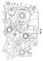
- FIG. 1is a top view of a latch housing wherein the intermittent lever is in the latched position and portions of the latch housing are illustrated in phantom;
- FIG. 1Ais a top view of the latch housing wherein the intermittent lever is in the latched position and the fork bolt and the detent lever are illustrated in phantom;
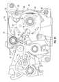
- FIG. 2is a top view of the latch housing wherein the intermittent lever is in an unlatched position and portions of the latch housing are removed or illustrated in phantom;
- FIG. 2Ais a top view of the latch housing wherein the intermittent lever is in the unlatched position and the fork bolt and the detent lever and portions of the latch housing are removed;
- FIG. 2Bis a top view of the latch housing wherein the intermittent lever is in the unlatched position and the fork bolt and the detent lever and a top or cover portion of the latch housing is not illustrated;
- FIG. 2Cis a top view of the latch housing wherein the intermittent lever is in the unlatched position and the fork bolt and the detent lever are illustrated is solid and a portion of the detent lever is cut away;
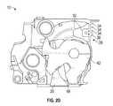
- FIG. 2Dis a view of the latch housing wherein the fork bolt is in the open position
- FIGS. 3 and 3Aare a side perspective view the latch housing illustrating a strengthening feature according to an alternative embodiment
- FIG. 4is perspective view of the overslam bumper with the elastomeric feature configured to contact the intermittent lever;
- FIG. 5is a bottom view of the latch housing.
- the latch 10is a vehicle door latch or any other vehicle latch or any other type of latch vehicular or otherwise.
- the housing of the latch 10may be formed from an easily molded material such a plastic or any suitable polymer.
- latch housing 10may be formed from a metal or metal alloy of combinations of metal, metal alloys and plastic.
- an intermittent lever 12is pivotally secured to the latch 10 for movement about an axis 15 between a first or latched position (See FIGS. 1 and 1A ) to a second or unlatched position (See FIGS. 2, 2A, 2B and 2C ) in the direction of arrows 70 . Movement of the intermittent lever 12 may be due to operation of an actuator (not shown) operatively coupled to the intermittent lever 12 .
- the intermittent lever 12is also operatively coupled to a detent lever or pawl 40 wherein movement of the intermittent lever 12 between the first or latched position to the second or unlatched position causes a corresponding movement of a detent lever or pawl between a first or engaged position and a second or disengaged position.
- the detent lever or pawl 40is configured to cooperate with a fork bolt or claw 42 of the latch 10 as is known in the related arts. For example, movement of the detent lever 40 to the first or engaged position prevents the fork bolt or claw 42 from moving from a latched position (illustrated in at least FIGS. 1A, 2A, 2B and 2C ) towards an open position (illustrated in FIG.
- Undesired noisesmay be generated by the intermittent ever 12 as it moves between the first or latched position to the second or unlatched position as in some designs the intermittent lever 12 may be allowed to move and resonate as the pawl or detent lever 42 stops abruptly against a rest bushing or other component of the latch 10 .
- a small elastomeric feature 14is positioned to contact the intermittent lever 12 when it is in the first or latched position illustrated in at least FIGS. 1, 1A . Contact with the elastomeric feature 14 will dampen or mitigate undesirable noises when the latch is operating.
- the elastomeric feature 14is formed from a rubber or an elastomer (e.g., neoprene, urethane, nitrile, etc. or any other equivalent material that is capable of being formed or molded into the desired configurations).
- the elastomeric feature 14is integrated into or integrally formed with a striker overslam bumper 16 that formed from any suitable material including but not limited to those mentioned above and has an integral portion 18 located in a throat 20 of a housing 22 of the latch 10 such that a striker 46 (illustrated by the dashed lines in FIG. 1A ) contacts the portion 18 when it is inserted all the way into throat 20 until it contacts bumper 16 .
- a striker 46illustrated by the dashed lines in FIG. 1A
- the striker 46is received into the throat 20 as fork bolt 42 rotates from the open position in FIG. 2D in a direction opposite to arrow 44 and striker 46 is received within a throat 48 of the fork bolt 42 .
- portion 18may be deflected inwardly in the direction of arrow 50 as the striker 46 is received within throat 20 . During this movement, portion 26 may rotate in the direction of arrow 52 . As shown in FIG. 4 , portion 26 or portions of portion 26 of the bumper 16 may be located above and/or below feature 14 such as a different plane than the portion that comprises elastomeric feature 14 . Of course, other configurations are contemplated to be within the scope of various embodiments of the present invention.
- a portion of the overslam bumper 16is extended to provide the elastomeric feature 14 that a portion of the intermittent lever 12 contacts when it is in the latched position thereby enhancing the overall sound quality of the latch 10 .
- the bumper 16may have an integral portion 18 located in a throat 20 of the latch housing 22 and extending therefrom is a leg portion 24 that terminates at portion 14 , which is configured and positioned to contact the intermittent lever 12 when it is in the latched position.
- the bumper 16also has another leg or portion 26 that extends from the bumper 16 in a different direction for use in other sound deadening or sound improvement applications.
- bumper 16may have numerous configurations in order to achieve various sound deadening or sound improvement for various independently moving components of the latch 10 .
- a strengthening feature 28is incorporated into housing 22 or a portion 30 of housing 22 (e.g., a housing having two or more portions secured together to form housing 22 when latch 10 is assembled).
- the housingmay comprise a lower housing portion and an upper housing portion.
- the housing or a portion thereofmay be subject to a load due to contact either directly or indirectly with a portion of the fork bolt or claw 42 .
- thisis due to the fork bolt or claw 42 contacting a bumper 32 located between a housing wall 34 and the moving or rotating fork bolt as it transitions through various stages of rotation or in particular to an overslam position wherein the fork bolt 42 rotates past a latched position due to the travel of the striker 46 in the direction of arrow 50 .
- the bumper 32is formed from any suitable rubber or elastomer material including but not limited to those mentioned above and may be located on or adjacent to an interior surface of the housing in particular housing wall 34 .
- the structural integrity of the latch housing 22is increased by locating a strengthening feature 28 proximate to the desired area of increased strength, which in one embodiment may be adjacent to bumper 32 .
- the strengthening feature 28may be integrally formed or molded with housing 22 as it is formed during any suitable manufacturing process (e.g., injection molding, 3D printing and equivalents thereof).
- this strengthening featuremay be provided by a plurality of ribs 36 located on an exterior surface 38 of a wall 34 of the latch housing 22 or a portion 30 thereof and on opposite side of the wall or interior surface that makes contact with or is adjacent to bumper 32 .
- the plurality of ribs 36may be vertically arranged and may also contribute to localized increased wall thickness proximate to bumper 32 .
- ribs 36may be vertically arranged and may be located to provide discrete areas of increased wall thickness adjacent to bumper 32 .
- FIGS. 1A, 2A, 2B and 2Cshow a portion of the fork bolt 42 contacting the bumper 32 .
- an improved latch and/or latch housingis provided. Moreover, this improved design is facilitated through no additional components as the strengthening feature is incorporated into the existing housing. Thereby saving piece cost as well as tooling costs. Still further and in one embodiment and by incorporating these features into the existing housing there is no requirement to change the tooling or fixtures required for the manufacture of the housing.
- the terms “first,” “second,” and the like, hereindo not denote any order, quantity, or importance, but rather are used to distinguish one element from another, and the terms “a” and “an” herein do not denote a limitation of quantity, but rather denote the presence of at least one of the referenced item.
- the terms “bottom” and “top”are used herein, unless otherwise noted, merely for convenience of description, and are not limited to any one position or spatial orientation.
Landscapes
- Lock And Its Accessories (AREA)
- Casings For Electric Apparatus (AREA)
- Vibration Dampers (AREA)
Abstract
Description
Claims (9)
Priority Applications (1)
| Application Number | Priority Date | Filing Date | Title |
|---|---|---|---|
| US14/598,840US10450782B2 (en) | 2014-01-17 | 2015-01-16 | Apparatus and method for enhancing sound performance of a latch |
Applications Claiming Priority (3)
| Application Number | Priority Date | Filing Date | Title |
|---|---|---|---|
| US201461928642P | 2014-01-17 | 2014-01-17 | |
| US201461928675P | 2014-01-17 | 2014-01-17 | |
| US14/598,840US10450782B2 (en) | 2014-01-17 | 2015-01-16 | Apparatus and method for enhancing sound performance of a latch |
Publications (2)
| Publication Number | Publication Date |
|---|---|
| US20150204114A1 US20150204114A1 (en) | 2015-07-23 |
| US10450782B2true US10450782B2 (en) | 2019-10-22 |
Family
ID=53544338
Family Applications (2)
| Application Number | Title | Priority Date | Filing Date |
|---|---|---|---|
| US14/598,840Expired - Fee RelatedUS10450782B2 (en) | 2014-01-17 | 2015-01-16 | Apparatus and method for enhancing sound performance of a latch |
| US14/598,859AbandonedUS20150204115A1 (en) | 2014-01-17 | 2015-01-16 | Latch housing with strengthening feature |
Family Applications After (1)
| Application Number | Title | Priority Date | Filing Date |
|---|---|---|---|
| US14/598,859AbandonedUS20150204115A1 (en) | 2014-01-17 | 2015-01-16 | Latch housing with strengthening feature |
Country Status (2)
| Country | Link |
|---|---|
| US (2) | US10450782B2 (en) |
| CN (4) | CN104963568B (en) |
Cited By (4)
| Publication number | Priority date | Publication date | Assignee | Title |
|---|---|---|---|---|
| US11965364B2 (en)* | 2017-09-05 | 2024-04-23 | Kiekert Ag | Motor vehicle lock with braking element |
| USD1057635S1 (en)* | 2022-06-13 | 2025-01-14 | Inteva Products, Llc | Vehicle latch |
| USD1057636S1 (en)* | 2022-07-22 | 2025-01-14 | Inteva Products, Llc | Vehicle latch |
| USD1082491S1 (en) | 2022-07-22 | 2025-07-08 | Inteva Products, Llc | Vehicle latch |
Families Citing this family (6)
| Publication number | Priority date | Publication date | Assignee | Title |
|---|---|---|---|---|
| US10450782B2 (en)* | 2014-01-17 | 2019-10-22 | Inteva Products, Llc | Apparatus and method for enhancing sound performance of a latch |
| JP6435561B2 (en)* | 2014-10-29 | 2018-12-12 | 三井金属アクト株式会社 | Vehicle door latch device |
| CN106481162A (en)* | 2015-08-28 | 2017-03-08 | 昆山麦格纳汽车系统有限公司 | Clamp reduces noise structure |
| CN110344677B (en)* | 2019-06-14 | 2021-02-26 | 浙江吉利控股集团有限公司 | A car door lock with a buffer device and a vehicle |
| US11560738B2 (en)* | 2019-06-28 | 2023-01-24 | Nissan North America, Inc. | Door lock assembly for a vehicle door panel |
| US20250043600A1 (en)* | 2023-08-02 | 2025-02-06 | Kiekert Ag | Motor vehicle lock - in particular, motor vehicle side door lock |
Citations (40)
| Publication number | Priority date | Publication date | Assignee | Title |
|---|---|---|---|---|
| US3705738A (en)* | 1969-10-04 | 1972-12-12 | Aisin Seiki | Door latch mechanism |
| US3969789A (en) | 1975-05-27 | 1976-07-20 | General Motors Corporation | Door hold-open mechanism |
| US4586737A (en)* | 1984-08-22 | 1986-05-06 | General Motors Corporation | Vehicle body door lock |
| US4854617A (en)* | 1986-06-28 | 1989-08-08 | Aisin Seiki Kabushiki Kaisha | Door lock for automotive vehicles |
| US5020838A (en)* | 1988-09-30 | 1991-06-04 | Aisin Seiki Kabushiki Kaisha | Luggage-door lock device |
| US5106134A (en)* | 1988-03-31 | 1992-04-21 | Ktm Locks, Cmt Group, Division Of Magna International Inc. | Latch housing & striker for being secured in the latch housing |
| JPH04131484A (en)* | 1990-09-25 | 1992-05-06 | Mitsui Mining & Smelting Co Ltd | Abnormal sound preventive device at the time of engagement of car locking device |
| JPH05156854A (en)* | 1991-12-02 | 1993-06-22 | Mitsui Mining & Smelting Co Ltd | Vehicle door locking device |
| GB2321928A (en)* | 1997-02-04 | 1998-08-12 | Menitor Light Vehicle Systems (Uk) Limited | Latch Assembly |
| JPH11182113A (en) | 1997-12-24 | 1999-07-06 | Honda Lock Mfg Co Ltd | Vehicular door lock device |
| EP0995870A1 (en)* | 1998-10-23 | 2000-04-26 | ATOMA ROLTRA S.p.A. | Lock for a door of a motor vehicle |
| US6419286B1 (en)* | 1997-12-16 | 2002-07-16 | Huf Hülsbeck & Fürst Gmbh & Co. Kg | Rotary latch lock, especially for motor vehicles |
| JP2003113687A (en)* | 2001-10-03 | 2003-04-18 | Honda Lock Mfg Co Ltd | Door lock device for vehicle |
| US6568741B1 (en) | 2002-06-26 | 2003-05-27 | General Motors Corporation | Door hinge for vehicle |
| US6679531B2 (en) | 2001-05-03 | 2004-01-20 | Delphi Technologies, Inc. | Vehicle compartment latch |
| US6698805B2 (en)* | 2001-01-02 | 2004-03-02 | Robert Bosch Gmbh | Motor vehicle electric door lock |
| US6789825B2 (en)* | 2000-03-23 | 2004-09-14 | Meritor Light Vehicle Systems (Uk) Limited | Latch mechanism |
| US7156430B2 (en)* | 2004-06-22 | 2007-01-02 | Tri/Mark Corporation | Latch assembly |
| US7195292B2 (en)* | 2003-09-19 | 2007-03-27 | Arvinmeritor Light Vehicle Systems (Uk) Ltd. | Latch bolt |
| US7267380B2 (en)* | 2004-11-12 | 2007-09-11 | A.L. Hansen Manufacturing Co. | Rotary latch and housing |
| JP2007270573A (en) | 2006-03-31 | 2007-10-18 | Aisin Kiko Co Ltd | Vehicle door lock device |
| US7454933B1 (en)* | 2005-03-14 | 2008-11-25 | The Eastern Company | Handle and housing assembly |
| US20090224559A1 (en)* | 2008-03-05 | 2009-09-10 | Kia Motors Corporation | Door latch assembly with damping member of automobile |
| US20100127512A1 (en) | 2008-11-26 | 2010-05-27 | Inteva Products Llp | Vehicle door latch |
| US7789440B2 (en)* | 2003-05-08 | 2010-09-07 | Kiekert Ag | Motor vehicle door lock |
| US7845692B2 (en)* | 2005-06-16 | 2010-12-07 | Kiekert Ag | Motor vehicle door latch |
| CN201671445U (en) | 2010-04-29 | 2010-12-15 | 盈佳科技(长春)有限公司 | Fastener |
| US20110133493A1 (en) | 2009-12-08 | 2011-06-09 | Perkins Donald M | Vehicle door latch |
| US20110204659A1 (en) | 2010-02-18 | 2011-08-25 | Eduardo Estrada | Vehicle door latch |
| US8235428B2 (en)* | 2009-07-14 | 2012-08-07 | Kiekert Ag | Lock unit having a slotted pawl |
| US20120292927A1 (en) | 2011-05-19 | 2012-11-22 | Francisco Javier Vazquez | Vehicle latch |
| US8342582B2 (en)* | 2008-07-03 | 2013-01-01 | Kiekert Ag | Absorber element for a motor vehicle lock |
| US8348310B2 (en) | 2009-08-06 | 2013-01-08 | Inteva Products, Llc | Hold open lever integrated to latch housing |
| US8398128B2 (en)* | 2007-09-14 | 2013-03-19 | Inteva Products, Llc | Vehicle door latch system |
| EP2626490A2 (en) | 2012-02-10 | 2013-08-14 | Huf Hülsbeck & Fürst GmbH & Co. KG | Lock assembly |
| US20140292000A1 (en) | 2013-03-29 | 2014-10-02 | Francisco Javier Vazquez | Apparatus and method for preventing undesired engagement of hold open lever in a latch |
| US8888150B2 (en)* | 2012-04-11 | 2014-11-18 | Mitsui Kinzoku Act Corporation | Latch device for vehicle |
| US20150204115A1 (en)* | 2014-01-17 | 2015-07-23 | Kurt E. Nurmi | Latch housing with strengthening feature |
| US9151092B2 (en)* | 2008-11-19 | 2015-10-06 | Kiekert Ag | Lock unit having a multi-pawl locking mechanism |
| US9777515B2 (en)* | 2012-02-28 | 2017-10-03 | Kiekert Aktiengesellschaft | Motor-vehicle door lock |
- 2015
- 2015-01-16USUS14/598,840patent/US10450782B2/ennot_activeExpired - Fee Related
- 2015-01-16USUS14/598,859patent/US20150204115A1/ennot_activeAbandoned
- 2015-01-19CNCN201510026160.8Apatent/CN104963568B/ennot_activeExpired - Fee Related
- 2015-01-19CNCN201520036019.1Upatent/CN204984005U/ennot_activeExpired - Fee Related
- 2015-01-19CNCN201520036414.XUpatent/CN204850794U/ennot_activeExpired - Fee Related
- 2015-01-19CNCN201510026399.5Apatent/CN104895423B/ennot_activeExpired - Fee Related
Patent Citations (42)
| Publication number | Priority date | Publication date | Assignee | Title |
|---|---|---|---|---|
| US3705738A (en)* | 1969-10-04 | 1972-12-12 | Aisin Seiki | Door latch mechanism |
| US3969789A (en) | 1975-05-27 | 1976-07-20 | General Motors Corporation | Door hold-open mechanism |
| US4586737A (en)* | 1984-08-22 | 1986-05-06 | General Motors Corporation | Vehicle body door lock |
| US4854617A (en)* | 1986-06-28 | 1989-08-08 | Aisin Seiki Kabushiki Kaisha | Door lock for automotive vehicles |
| US5106134A (en)* | 1988-03-31 | 1992-04-21 | Ktm Locks, Cmt Group, Division Of Magna International Inc. | Latch housing & striker for being secured in the latch housing |
| US5020838A (en)* | 1988-09-30 | 1991-06-04 | Aisin Seiki Kabushiki Kaisha | Luggage-door lock device |
| JPH04131484A (en)* | 1990-09-25 | 1992-05-06 | Mitsui Mining & Smelting Co Ltd | Abnormal sound preventive device at the time of engagement of car locking device |
| JPH05156854A (en)* | 1991-12-02 | 1993-06-22 | Mitsui Mining & Smelting Co Ltd | Vehicle door locking device |
| GB2321928A (en)* | 1997-02-04 | 1998-08-12 | Menitor Light Vehicle Systems (Uk) Limited | Latch Assembly |
| US6419286B1 (en)* | 1997-12-16 | 2002-07-16 | Huf Hülsbeck & Fürst Gmbh & Co. Kg | Rotary latch lock, especially for motor vehicles |
| JPH11182113A (en) | 1997-12-24 | 1999-07-06 | Honda Lock Mfg Co Ltd | Vehicular door lock device |
| EP0995870A1 (en)* | 1998-10-23 | 2000-04-26 | ATOMA ROLTRA S.p.A. | Lock for a door of a motor vehicle |
| US6789825B2 (en)* | 2000-03-23 | 2004-09-14 | Meritor Light Vehicle Systems (Uk) Limited | Latch mechanism |
| US6698805B2 (en)* | 2001-01-02 | 2004-03-02 | Robert Bosch Gmbh | Motor vehicle electric door lock |
| US6679531B2 (en) | 2001-05-03 | 2004-01-20 | Delphi Technologies, Inc. | Vehicle compartment latch |
| JP2003113687A (en)* | 2001-10-03 | 2003-04-18 | Honda Lock Mfg Co Ltd | Door lock device for vehicle |
| US6568741B1 (en) | 2002-06-26 | 2003-05-27 | General Motors Corporation | Door hinge for vehicle |
| US7789440B2 (en)* | 2003-05-08 | 2010-09-07 | Kiekert Ag | Motor vehicle door lock |
| US7195292B2 (en)* | 2003-09-19 | 2007-03-27 | Arvinmeritor Light Vehicle Systems (Uk) Ltd. | Latch bolt |
| US7156430B2 (en)* | 2004-06-22 | 2007-01-02 | Tri/Mark Corporation | Latch assembly |
| US7267380B2 (en)* | 2004-11-12 | 2007-09-11 | A.L. Hansen Manufacturing Co. | Rotary latch and housing |
| US7454933B1 (en)* | 2005-03-14 | 2008-11-25 | The Eastern Company | Handle and housing assembly |
| US7845692B2 (en)* | 2005-06-16 | 2010-12-07 | Kiekert Ag | Motor vehicle door latch |
| JP2007270573A (en) | 2006-03-31 | 2007-10-18 | Aisin Kiko Co Ltd | Vehicle door lock device |
| US8398128B2 (en)* | 2007-09-14 | 2013-03-19 | Inteva Products, Llc | Vehicle door latch system |
| US20090224559A1 (en)* | 2008-03-05 | 2009-09-10 | Kia Motors Corporation | Door latch assembly with damping member of automobile |
| US8342582B2 (en)* | 2008-07-03 | 2013-01-01 | Kiekert Ag | Absorber element for a motor vehicle lock |
| US9151092B2 (en)* | 2008-11-19 | 2015-10-06 | Kiekert Ag | Lock unit having a multi-pawl locking mechanism |
| US20100127512A1 (en) | 2008-11-26 | 2010-05-27 | Inteva Products Llp | Vehicle door latch |
| WO2010062805A2 (en) | 2008-11-26 | 2010-06-03 | Inteva Products Llc. | Vehicle door latch |
| US8235428B2 (en)* | 2009-07-14 | 2012-08-07 | Kiekert Ag | Lock unit having a slotted pawl |
| US8348310B2 (en) | 2009-08-06 | 2013-01-08 | Inteva Products, Llc | Hold open lever integrated to latch housing |
| US20110133493A1 (en) | 2009-12-08 | 2011-06-09 | Perkins Donald M | Vehicle door latch |
| CN102858566A (en) | 2009-12-08 | 2013-01-02 | 因特瓦产品有限责任公司 | Vehicle door latch |
| US20110204659A1 (en) | 2010-02-18 | 2011-08-25 | Eduardo Estrada | Vehicle door latch |
| CN201671445U (en) | 2010-04-29 | 2010-12-15 | 盈佳科技(长春)有限公司 | Fastener |
| US20120292927A1 (en) | 2011-05-19 | 2012-11-22 | Francisco Javier Vazquez | Vehicle latch |
| EP2626490A2 (en) | 2012-02-10 | 2013-08-14 | Huf Hülsbeck & Fürst GmbH & Co. KG | Lock assembly |
| US9777515B2 (en)* | 2012-02-28 | 2017-10-03 | Kiekert Aktiengesellschaft | Motor-vehicle door lock |
| US8888150B2 (en)* | 2012-04-11 | 2014-11-18 | Mitsui Kinzoku Act Corporation | Latch device for vehicle |
| US20140292000A1 (en) | 2013-03-29 | 2014-10-02 | Francisco Javier Vazquez | Apparatus and method for preventing undesired engagement of hold open lever in a latch |
| US20150204115A1 (en)* | 2014-01-17 | 2015-07-23 | Kurt E. Nurmi | Latch housing with strengthening feature |
Non-Patent Citations (16)
| Title |
|---|
| CN Application No. 20151002616038 Office Action; dated Nov. 4, 2016. |
| CN Application No. 201510026399.5 Office Action; dated Dec. 8, 2016. |
| CN Application No. 201510026399.5 Search Report. |
| CN Application No. 201520036414.X Office Action; dated May 22, 2015. |
| English Abstract for CN102858566. |
| English Abstract for CN201671445. |
| English Abstract for EP2626490. |
| English Abstract for JP2007270573. |
| English Abstract for JPH1182113. |
| English Machine Translation of Specification and Claims for CN102858566. |
| English Machine Translation of Specification and Claims for CN201671445. |
| English Machine Translation of Specification and Claims for EP2626490. |
| English Machine Translation of Specification and Claims for JP2007270573. |
| English Machine Translation of Specification and Claims for JPH1182113. |
| English Translation for CN Application No. 20151002616038 Office Action; dated Nov. 4, 2016. |
| English Translation for CN Application No. 201510026399.5 Office Action; dated Dec. 8, 2016. |
Cited By (4)
| Publication number | Priority date | Publication date | Assignee | Title |
|---|---|---|---|---|
| US11965364B2 (en)* | 2017-09-05 | 2024-04-23 | Kiekert Ag | Motor vehicle lock with braking element |
| USD1057635S1 (en)* | 2022-06-13 | 2025-01-14 | Inteva Products, Llc | Vehicle latch |
| USD1057636S1 (en)* | 2022-07-22 | 2025-01-14 | Inteva Products, Llc | Vehicle latch |
| USD1082491S1 (en) | 2022-07-22 | 2025-07-08 | Inteva Products, Llc | Vehicle latch |
Also Published As
| Publication number | Publication date |
|---|---|
| US20150204115A1 (en) | 2015-07-23 |
| CN104895423B (en) | 2017-10-31 |
| CN104963568B (en) | 2018-01-23 |
| CN204984005U (en) | 2016-01-20 |
| CN104963568A (en) | 2015-10-07 |
| CN104895423A (en) | 2015-09-09 |
| CN204850794U (en) | 2015-12-09 |
| US20150204114A1 (en) | 2015-07-23 |
Similar Documents
| Publication | Publication Date | Title |
|---|---|---|
| US10450782B2 (en) | Apparatus and method for enhancing sound performance of a latch | |
| JP6005782B2 (en) | Vehicle latch device | |
| CN101557953B (en) | Vehicle door and method for manufacturing the same | |
| CN102975775B (en) | Vehicle body | |
| JP4388048B2 (en) | Garnish for vehicles | |
| US9879449B2 (en) | Vehicle latch assembly and method of dampening sound during a closing process of the vehicle latch assembly | |
| US6755405B2 (en) | Rubber bearing comprising a reinforcing element | |
| JP2007237843A (en) | Fuel tank | |
| JP5844075B2 (en) | Vehicle latch device | |
| US9758995B2 (en) | Latch buffer assembly | |
| JP2010173348A (en) | Back door of automobile | |
| JP4733066B2 (en) | Tube clamp | |
| JP4864483B2 (en) | Vehicle door structure | |
| US9493968B2 (en) | Striker with expandable sleeve | |
| JP7481172B2 (en) | Vehicle hood biasing device | |
| KR20110023099A (en) | Guide bumper integrated striker in the vehicle | |
| JP6119626B2 (en) | Pop-up hood device for vehicle | |
| JP4538384B2 (en) | Inside door handle device | |
| JP6983207B2 (en) | Vehicle lock structure | |
| KR102562788B1 (en) | Friction hinge unit for automobile console box and assembly method thereof | |
| KR20130032616A (en) | A door trim assembly | |
| JP7179606B2 (en) | Electric actuator and door latch device | |
| JP2019007659A (en) | Duct structure | |
| JP2017179780A (en) | Opening and closing body locking device | |
| EP2840207A2 (en) | Energy dampening arrangement for vehicle latch assembly |
Legal Events
| Date | Code | Title | Description |
|---|---|---|---|
| AS | Assignment | Owner name:INTEVA PRODUCTS, LLC, MICHIGAN Free format text:ASSIGNMENT OF ASSIGNORS INTEREST;ASSIGNORS:NURMI, KURT E.;RABAGO, JULIA;TERRAZAS, ROGELIO;AND OTHERS;SIGNING DATES FROM 20150205 TO 20150212;REEL/FRAME:035171/0663 | |
| AS | Assignment | Owner name:DEUTSCHE BANK AG NEW YORK BRANCH, AS COLLATERAL AGENT, NEW YORK Free format text:SECURITY AGREEMENT;ASSIGNOR:INTEVA PRODUCTS, LLC;REEL/FRAME:039973/0305 Effective date:20160908 Owner name:DEUTSCHE BANK AG NEW YORK BRANCH, AS COLLATERAL AG Free format text:SECURITY AGREEMENT;ASSIGNOR:INTEVA PRODUCTS, LLC;REEL/FRAME:039973/0305 Effective date:20160908 | |
| AS | Assignment | Owner name:WELLS FARGO BANK, NATIONAL ASSOCIATION, NEW YORK Free format text:SECURITY AGREEMENT;ASSIGNOR:INTEVA PRODUCTS, LLC;REEL/FRAME:042857/0001 Effective date:20160908 | |
| AS | Assignment | Owner name:INTEVA PRODUCTS, LLC, MICHIGAN Free format text:RELEASE BY SECURED PARTY;ASSIGNOR:DEUTSCHE BANK AG NEW YORK BRANCH;REEL/FRAME:043038/0246 Effective date:20170627 | |
| STPP | Information on status: patent application and granting procedure in general | Free format text:NON FINAL ACTION MAILED | |
| STPP | Information on status: patent application and granting procedure in general | Free format text:RESPONSE TO NON-FINAL OFFICE ACTION ENTERED AND FORWARDED TO EXAMINER | |
| STPP | Information on status: patent application and granting procedure in general | Free format text:NOTICE OF ALLOWANCE MAILED -- APPLICATION RECEIVED IN OFFICE OF PUBLICATIONS | |
| STCF | Information on status: patent grant | Free format text:PATENTED CASE | |
| AS | Assignment | Owner name:CERBERUS BUSINESS FINANCE, LLC, AS COLLATERAL AGENT, NEW YORK Free format text:PATENT SECURITY AGREEMENT;ASSIGNOR:INTEVA PRODUCTS, LLC;REEL/FRAME:059766/0348 Effective date:20220322 | |
| FEPP | Fee payment procedure | Free format text:MAINTENANCE FEE REMINDER MAILED (ORIGINAL EVENT CODE: REM.); ENTITY STATUS OF PATENT OWNER: LARGE ENTITY | |
| LAPS | Lapse for failure to pay maintenance fees | Free format text:PATENT EXPIRED FOR FAILURE TO PAY MAINTENANCE FEES (ORIGINAL EVENT CODE: EXP.); ENTITY STATUS OF PATENT OWNER: LARGE ENTITY | |
| STCH | Information on status: patent discontinuation | Free format text:PATENT EXPIRED DUE TO NONPAYMENT OF MAINTENANCE FEES UNDER 37 CFR 1.362 | |
| FP | Lapsed due to failure to pay maintenance fee | Effective date:20231022 |