US10449048B2 - Mitral valve annuloplasty device with twisted anchor - Google Patents
Mitral valve annuloplasty device with twisted anchorDownload PDFInfo
- Publication number
- US10449048B2 US10449048B2US15/368,467US201615368467AUS10449048B2US 10449048 B2US10449048 B2US 10449048B2US 201615368467 AUS201615368467 AUS 201615368467AUS 10449048 B2US10449048 B2US 10449048B2
- Authority
- US
- United States
- Prior art keywords
- anchor
- segment
- expandable
- distal
- configuration
- Prior art date
- Legal status (The legal status is an assumption and is not a legal conclusion. Google has not performed a legal analysis and makes no representation as to the accuracy of the status listed.)
- Expired - Lifetime
Links
Images


Classifications
- A—HUMAN NECESSITIES
- A61—MEDICAL OR VETERINARY SCIENCE; HYGIENE
- A61F—FILTERS IMPLANTABLE INTO BLOOD VESSELS; PROSTHESES; DEVICES PROVIDING PATENCY TO, OR PREVENTING COLLAPSING OF, TUBULAR STRUCTURES OF THE BODY, e.g. STENTS; ORTHOPAEDIC, NURSING OR CONTRACEPTIVE DEVICES; FOMENTATION; TREATMENT OR PROTECTION OF EYES OR EARS; BANDAGES, DRESSINGS OR ABSORBENT PADS; FIRST-AID KITS
- A61F2/00—Filters implantable into blood vessels; Prostheses, i.e. artificial substitutes or replacements for parts of the body; Appliances for connecting them with the body; Devices providing patency to, or preventing collapsing of, tubular structures of the body, e.g. stents
- A61F2/02—Prostheses implantable into the body
- A61F2/24—Heart valves ; Vascular valves, e.g. venous valves; Heart implants, e.g. passive devices for improving the function of the native valve or the heart muscle; Transmyocardial revascularisation [TMR] devices; Valves implantable in the body
- A61F2/2442—Annuloplasty rings or inserts for correcting the valve shape; Implants for improving the function of a native heart valve
- A61F2/2451—Inserts in the coronary sinus for correcting the valve shape
- A—HUMAN NECESSITIES
- A61—MEDICAL OR VETERINARY SCIENCE; HYGIENE
- A61F—FILTERS IMPLANTABLE INTO BLOOD VESSELS; PROSTHESES; DEVICES PROVIDING PATENCY TO, OR PREVENTING COLLAPSING OF, TUBULAR STRUCTURES OF THE BODY, e.g. STENTS; ORTHOPAEDIC, NURSING OR CONTRACEPTIVE DEVICES; FOMENTATION; TREATMENT OR PROTECTION OF EYES OR EARS; BANDAGES, DRESSINGS OR ABSORBENT PADS; FIRST-AID KITS
- A61F2/00—Filters implantable into blood vessels; Prostheses, i.e. artificial substitutes or replacements for parts of the body; Appliances for connecting them with the body; Devices providing patency to, or preventing collapsing of, tubular structures of the body, e.g. stents
- A61F2/02—Prostheses implantable into the body
- A61F2/24—Heart valves ; Vascular valves, e.g. venous valves; Heart implants, e.g. passive devices for improving the function of the native valve or the heart muscle; Transmyocardial revascularisation [TMR] devices; Valves implantable in the body
- A61F2/2442—Annuloplasty rings or inserts for correcting the valve shape; Implants for improving the function of a native heart valve
- A61F2/2466—Delivery devices therefor
Definitions
- This inventionrelates generally to devices and methods for shaping tissue by deploying one or more devices in body lumens adjacent to the tissue.
- One particular application of the inventionrelates to a treatment for mitral valve regurgitation through deployment of a tissue shaping device in the patient's coronary sinus or great cardiac vein.
- the mitral valveis a portion of the heart that is located between the chambers of the left atrium and the left ventricle. When the left ventricle contracts to pump blood throughout the body, the mitral valve closes to prevent the blood being pumped back into the left atrium. In some patients, whether due to genetic malformation, disease or injury, the mitral valve fails to close properly causing a condition known as regurgitation, whereby blood is pumped into the atrium upon each contraction of the heart muscle. Regurgitation is a serious, often rapidly deteriorating, condition that reduces circulatory efficiency and must be corrected.
- Two of the more common techniques for restoring the function of a damaged mitral valveare to surgically replace the valve with a mechanical valve or to suture a flexible ring around the valve to support it.
- Each of these proceduresis highly invasive because access to the heart is obtained through an opening in the patient's chest.
- Patients with mitral valve regurgitationare often relatively frail thereby increasing the risks associated with such an operation.
- a device to perform mitral valve annuloplastyis therefore needed that can be implanted percutaneously without opening the chest wall.
- tissue shaping devicesuch as a percutaneous mitral valve annuloplasty device
- the devicecomprises a first anchor and a second anchor adapted to be deployed by a catheter to engage a vessel wall, wherein the first anchor includes a shaping feature adapted to resist the compression of a first part of the first anchor and resist the expansion of a second part of the first anchor in response to a compressive force on the first part, and a support structure disposed between and operatively connecting the first anchor and the second anchor.
- the anchorsare adapted to engage a coronary sinus.
- the first anchorcomprises two entwisted wire segments, possibly arranged in a figure-8 configuration having first and second aims coupled at least one coupling point (formed from, e.g., entwisted wire) as the shaping feature.
- the coupling pointis substantially at an apex of the first anchor when the anchor is in its deployed configuration.
- the anchor's widthis greater than its height in its deployed configuration.
- the devicealso includes an anchor lock adapted to lock the first anchor and/or the second anchor in an expanded configuration.
- the devicehas a coupler, which may include a tether and a hitch wire, which is adapted to couple the device to a delivery tool.
- the coupleris further adapted to release the device from the delivery tool.
- the deviceis adapted to be recaptured by the catheter.
- One aspect of the inventionis a method of performing mitral valve annuloplasty on a patient's heart.
- the methodcomprises percutaneously delivering a mitral valve annuloplasty device to a vessel in the patient's heart, where the device comprises first and second anchors and a support structure disposed between and operatively connecting the first and second anchors, anchoring the first anchor of the mitral valve annuloplasty device in the vessel, resisting compression of a first part of the first anchor and resisting expansion of a second part of the first anchor in response to a compressive force on the first part, and anchoring the second anchor of the mitral valve annuloplasty device.
- the first anchoring stepcomprises expanding the first anchor from a delivery configuration to a deployed configuration in which the first anchor engages the coronary sinus.
- the anchor's width in the deployed configurationis greater than its height.
- the methodincludes locking the first anchor in the deployed configuration.
- the second anchoring stepincludes expanding the second anchor from a delivery configuration to a deployed configuration in which the second anchor engages the coronary sinus. In some embodiments the method includes locking the second anchor in the deployed configuration.
- the methodincludes capturing the first anchor and/or the second anchor within the catheter after the first anchoring step.
- the capturing stepmay include advancing a catheter distally over the anchor to place the anchor inside the catheter in the delivery configuration.
- the methodincludes applying a proximally directed force on the mitral valve annuloplasty device after the first anchoring step.
- the methodincludes uncoupling the device from a delivery tool after the second anchoring step. The uncoupling may comprise releasing a hitch wire from the device and removing a tether from the device.
- FIG. 1is a superior view of a heart with the atria removed.
- FIG. 2illustrates one embodiment of an intravascular device deployed in a coronary sinus.
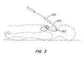
- FIG. 3illustrates one embodiment of delivering an intravascular device to a desired location within a patient's body.
- FIG. 4shows one embodiment of an intravascular device with proximal anchor and distal anchor in their expanded and locked configurations.
- FIG. 5shows details of the distal anchor of FIG. 4 with a shaping feature of two entwisted wire segments.
- FIG. 6illustrates an exemplary coupler that may be used with an intravascular device.
- FIG. 7shows an exemplary delivery tool that may be used to deliver and deploy an intravascular device.
- the present inventionrelates to a medical device and uses thereof that supports or changes the shape of tissue near a vessel in which the device is placed.
- the present inventionis particularly useful in reducing mitral valve regurgitation by changing the shape of or supporting a mitral valve annulus.
- the devicecomprises a distal anchor adapted to be anchored in the coronary sinus which resists a compression of a distal part of the anchor and an expansion of a proximal part of the anchor in response to a compressive force on the distal part of the anchor.
- coronary sinusrefers to not only the coronary sinus itself, but also to the venous system associated with the coronary sinus, including the great cardiac vein.
- FIG. 1is a superior view of a heart 100 with the atria removed.
- the heartcomprises several valves including mitral valve 102 , pulmonary valve 104 , aortic valve 106 and tricuspid valve 108 .
- Mitral valve 102includes anterior cusp 110 , posterior cusp 112 and annulus 114 .
- Annulus 114encircles cusps 110 and 112 and functions to maintain their respective spacing to ensure complete mitral valve closure during left ventricular contractions of the heart 100 .
- coronary sinus 116partially encircles mitral valve 102 and is adjacent to mitral valve annulus 114 .
- Coronary sinus 116is part of the venous system of heart 100 and extends along the AV groove between the left atrium and the left ventricle. This places coronary sinus 116 essentially within the same plane as mitral valve annulus 114 , making coronary sinus 116 available for placement of shaping device 200 in order to reshape mitral valve geometry and to restore proper valve function.
- FIG. 2illustrates one possible embodiment of an intravascular tissue shaping device 400 which is deployable in coronary sinus 116 .
- device 400generally comprises an elongated connector 220 disposed between a distal anchor 240 and a proximal anchor 260 . Both distal anchor 240 and proximal anchor 260 are shown in their deployed, or expanded, configurations, securely positioned within the coronary sinus 116 .
- FIG. 2further depicts, in phantom, a delivery tool 300 comprising catheter 302 for delivering and positioning intravascular device 400 in the coronary sinus 116 .
- FIG. 3illustrates one embodiment of delivering the intravascular device of the present invention to a desired location within a patient's body.
- An incision 80is made in the patient's skin to gain access to a blood vessel.
- the blood vesselmay be, for example, the jugular vein.
- a guide catheter 210is advanced through the patient's vasculature until its distal end is positioned near the desired location for the intravascular device.
- a delivery catheter and advancing mechanism 310are inserted through the guide catheter 210 to deploy the intravascular device at the desired location in the patient's body.
- the delivery catheteris advanced until its distal end is inside the coronary sinus.
- FIG. 4shows one embodiment of an intravascular shaping device 400 with proximal anchor 402 and distal anchor 404 in their expanded and locked configurations.
- proximal anchor 402is made from a shape memory metal wire, for example Nitinol, extending from a crimp 406 .
- Stress relief portions 408 of the wireextend distal to crimp 406 .
- the wireextends upward from stress relief portions 408 to form vessel engagement portions 410 which cross to form a figure-8 pattern, as shown.
- Vessel engagement portions 410 and crimp 406engage the inner wall of the coronary sinus or other vessel in which the device is implanted.
- the vesselmay be a superior vena cava as described in U.S. application Ser. No. 11/279,352, filed Apr.
- proximal anchor 402may be provided with variable slope recapture features, as described in U.S. patent application Ser. No. 10/429,172, filed May 2, 2003.
- the distal anchoris made from a shape memory wire extending from a crimp 418 .
- Stress relief portions 420 of the wireextend distal to crimp 418 .
- the wireextends upward from stress relief portions 420 to form vessel engagement portions 422 which twist around one another, which is described in further detail below.
- Vessel engagement portions 422 and crimp 418engage the inner wall of the coronary sinus or other vessel in which the device is implanted.
- the wirealso forms a lock loop 424 .
- a bent portion 407 of connector 426interacts with wire portion 428 and lock loop 424 to form a distal anchor lock to secure the distal anchor in an expanded configuration. Actuation of the proximal and distal anchor locks is further described in U.S. application Ser. No. 10/946,332, now U.S. Pat. No. 7,837,729, and U.S. application Ser. No. 10/945,855, now U.S. Pat. No. 8,182,529.
- connectors 426 and 428are both made of shape memory metal, such as Nitinol. By spanning the distance between proximal anchor 402 and distal anchor 404 , connectors 426 and 428 maintain the reshaping force on the tissue.
- tissue shaping devicessuch as those shown in FIG. 4 may be stored in cartridges or other containers, such as described in U.S. application Ser. No. 10/946,332, now U.S. Pat. No. 7,837,729, and U.S. application Ser. No. 10/945,855, now U.S. Pat. No. 8,182,529, then delivered to the coronary sinus or other vessel in a delivery catheter, as shown in FIG. 2 .
- the wire forming the distal anchor 404has one end positioned within crimp 418 .
- a first wire segment 452 of the distal anchorextends distally from the distal crimp, then bends radially outward from the longitudinal axis of the crimp.
- the wirethen bends back proximally and radially inward where it twists around a second wire segment 462 at a coupling point substantially at the anchor's apex.
- the wirethen wraps around the connectors 426 and 428 to form distal lock loop 424 before extending radially outwards and distally where it becomes the second wire segment 462 .
- the second wire segment 462bends proximally into the distal end of the distal crimp 418 .
- the location of the coronary sinus in which the distal anchor may be deployedmay be tapered as the diameter along the length of the vessel decreases.
- Branching vesselsmay also contribute to a non-uniform diameter of the coronary sinus.
- the diameter of the coronary sinus where the distal part of the distal anchor contacts the coronary sinus wallmay be narrower than the diameter where the proximal part of the distal anchor contacts the coronary sinus wall.
- the vessel wallmay exert a larger compressive force on the distal part of the anchor than on the proximal part when the anchor is in a deployed configuration.
- This compressive forcemay cause compression of the distal end of the anchor, which can be transferred through the anchor and cause an expansion in a proximal part of the anchor.
- the distal anchormay not be able to anchor properly in the vessel.
- the distal anchormay compress and deform such that the amount of strain on the vessel is not great enough to allow the distal anchor to remain anchored in place.
- FIGS. 4 and 5illustrates a device with an anchor shaping feature adapted to resist a compressive force exerted on a distal part of an anchor and resisting an expansion of a proximal part of the anchor in response to a compressive force on the distal part.
- the device of the present inventionresists this compressive force on the distal part of the anchor and allows the device to anchor in place.
- the distal anchormaintains a strain on the vessel which allows for the device to be anchored in the vessel to reduce mitral valve regurgitation, as described below.
- the distal anchorresists compression of its distal part 502 and resists expansion of its proximal part 504 in response to a compressive force on the distal part 502 of the anchor.
- coupling of the anchor's arms via the twisted wire as shownacts to prevent a compressive force exerted on the distal part of the anchor from being transmitted through the anchor into the proximal part of the anchor.
- the twistresists a distally exerted compressive force by creating a resistance to such a force.
- the anchor as describedthus far resists a compressive force on the distal part of the anchor
- the anchor as adaptedmay also resist a compressive force on the proximal part of the anchor by creating a resistance when a compressive force is exerted on the proximal part of the anchor.
- the proximal anchor of an intravascular devicemay also be adapted to resist compressive forces from a vessel in which it might be deployed.
- FIGS. 4 and 5show one full twist of the two segments of the distal anchor, it is understood that a different number of twists may be used to carry out the intent of the invention and the number of twists shown is not a limitation.
- anchor shaping features other than entwisted wiresmay be used.
- the anchor's width(e.g., the maximum distance between anchor arms 422 in FIG. 4 ) may be greater than its height (e.g., the distance between crimp 418 and the twisted wire of anchor 404 ).
- the distal anchormay be about 14 mm high and about 17 mm wide. The height and size may, however, vary while still carrying out the purposes of the invention.
- the intravascular devicecomprises a coupler adapted to couple the intravascular device to a delivery tool.
- FIG. 6illustrates an exemplary coupler in use with a different intravascular device that may be used with the intravascular device of this invention.
- the couplercomprises a loop 202 at the end of tether 201 and a hitch wire 204 .
- Loop 202extends through arrowhead-shaped element 414 , and the hitch wire 204 passes through loop 202 and into the crimp, thereby preventing loop 202 from being withdrawn from arrowhead-shaped element 414 .
- FIG. 7shows an exemplary delivery tool 300 that may be used to deliver and deploy an intravascular device 400 via a catheter (not shown). Details of the operation of delivery tool 300 may be found in U.S. patent application Ser. No. 10/946,332, filed Sep. 20, 2004, now U.S. Pat. No. 7,837,729, and Ser. No. 10/945,855, filed Sep. 20, 2004, now U.S. Pat. No. 8,182,529.
- the intravascular deviceis preferably loaded into and delivered to a desired location within a catheter with the proximal and distal anchors in a delivery or collapsed condition.
- Medical personnelmay deploy the distal end of the intravascular device from the catheter into the lumen of a coronary sinus by advancing the intravascular device or by retracting the catheter, or a combination thereof.
- a delivery toolsuch as that of FIG. 7 may provide for distal movement of the intravascular device with respect to the catheter, and a tether may provide proximal movement of the device or for maintaining the position of the intravascular device relative to distal motion of a catheter.
- the distal anchorbegins to expand as soon as it is deployed from the catheter.
- the distal loop of the distal anchoris moved distally so that the distal anchor further expands and locks in place to securely engage the coronary sinus wall and remains in the locked expanded configuration.
- the vesselmay exert a compressive force on the distal part of the distal anchor, due to, for example, the narrowing diameter of the vessel.
- the distal anchoras adapted resists compression of the distal part therefore resisting expansion of a proximal part in response to this compressive force.
- the greater width of the distal anchor in comparison to its heighthelps create strain on the vessel to increase the anchoring action.
- the intravascular deviceis tensioned by pulling on the tether to apply a proximally-directed cinching force on the distal anchor, thereby modifying the shape of the coronary sinus and adjacent nearby valve annulus tissue.
- Fluoroscopy, ultrasound or other imaging technologymay be used to detect when the device modifies the shape of the mitral valve annulus sufficiently to reduce mitral valve regurgitation without otherwise adversely affecting the patient.
- a preferred method of assessing efficacy and safety during a mitral valve procedureis disclosed in U.S. patent application Ser. No. 10/366,585, filed Feb. 12, 2003.
- the proximal anchoris deployed in the coronary sinus, but it may be deployed in other vessels as well.
- the proximal loop of the proximal anchoris advanced distally over the arrowhead-shaped element by the delivery tool to further expand and lock the proximal anchor, thus engaging the coronary sinus wall or other vessel and maintaining a cinching force of the device on the mitral valve annulus.
- the coupler that couples the intravascular device to a delivery toolcan be released.
- a hitch wireis first withdrawn (by, for example, a hitch wire actuator of the delivery tool of FIG. 7 ), thereby releasing the loop so it can be pulled through the proximal lock, and thereby uncoupling the intravascular device from the delivery tool.
- the distal anchormay be recaptured into the delivery catheter by holding the intravascular device in place with a the tether while advancing the catheter distally over the distal anchor so that the entire intravascular device is once again inside the catheter.
- the distally directed force of the cathetercollapses the distal anchor to ease recapture into the catheter.
- the tethermay be used to pull the intravascular device proximally while holding the catheter stationary. Either motion, or a combination of motions, may be used to recapture the distal anchor.
- the intravascular devicemay be captured into the delivery catheter by holding the device in place with the tether while advancing a catheter distally first over a proximal anchor, over the support structure, and finally over a distal anchor.
- the distally directed force of the cathetercollapses the anchors such that they can again fit within the catheter.
- the tethermay also be used to pull the device proximally while holding the catheter stationary. If the coupler has been detached from the device prior to capture, the device may be recaptured into the delivery catheter or another catheter by grasping the proximal end of the device with a tether or grasper and by advancing the catheter distally over the device.
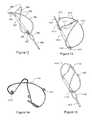
- FIGS. 8-19show embodiments of the device of this invention having flexible and expandable wire anchors which permit the delivery of tissue shaping devices 60 mm or less in length by a ten french (or less) catheter.
- one or both of the anchorsare provided with bending points about Which the anchors deform when placed in their unexpanded configuration for delivery by a catheter or recapture into a catheter. These bending points enable the anchors to deform into configurations that minimize overlap with other elements of the device.
- the distal anchoris self-expanding, thereby avoiding the need for a proximally-extending eyelet in the anchor's unexpanded configuration that might overlap with the unexpanded proximal anchor within the delivery and/or recapture catheter.
- FIG. 8shows an actuatable anchor design suitable for a shorter tissue shaping device similar to the device shown in FIGS. 8 and 9 .
- distal anchor 1300is disposed distal to a connector 1302 .
- anchor 1300is formed in a figure eight configuration from flexible wire such as nitinol held by a crimp tube 304 .
- An eyelet 306is formed around the longitudinal axis of connector 1302 . A distally directed actuation force on eyelet 306 moves it over a lock bump 308 formed in connector 1302 to actuate and lock anchor 1300 .
- FIG. 8shows anchor 1300 in an expanded configuration.
- eyelet 306is disposed proximal to lock hump 308 , and the figure eight loops of anchor 1300 are compressed against crimp 304 .
- eyelet 306In order to limit the proximal distance eyelet 306 must be moved along the connector to compress anchor 1300 into an unexpanded configuration, bending points 1310 are formed in the distal struts of anchor 1300 . Bending points 1310 are essentially kinks, i.e., points of increased curvature, formed in the wire.
- bending points 1310deform such that the upper arms 312 of the distal struts bend around bending points 1310 and move toward the lower arms 314 of the distal struts, thereby limiting the distance eyelet 306 and the anchor's proximal struts must be moved proximally along the connector to compress the anchor.
- anchor 1300would deform about bending points 1310 to limit the cross-sectional profile of the anchor within the catheter, even if eyelet 306 were not moved proximally over lock bump 308 during the recapture procedure. Bending points may also he provided on the proximal anchor in a similar fashion.
- distal anchor 1300may be part of a tissue shaping device (such as that shown in FIGS. 8 and 9 ) having a proximal anchor and a connector disposed between the anchors.
- tissue shaping devicesuch as that shown in FIGS. 8 and 9
- distal anchor 1300may he deployed from a catheter and expanded with an actuation force to anchor against the coronary sinus wall to provide an anchoring force of at least one pound, preferably at least two pounds, and to lock anchor 1300 in an expanded configuration.
- a proximally directed forceis applied to distal anchor 1300 through connector 1302 , such as by moving the proximal anchor proximally about 1-6 cm., more preferably at least 2 cm., by pulling on a tether or control wire operated from outside the patient.
- the proximal anchormay then be deployed to maintain the reshaping force of the device.
- anchor 1300is its ability to conform and adapt to a variety of vessel sizes. For example, when anchor 1300 is expanded inside a vessel such as the coronary sinus, the anchor's wire arms may contact the coronary sinus wall before the eyelet 306 has been advanced distally over lock hump 308 to lock the anchor in place. While continued distal advancement of eyelet 306 will create some outward force on the coronary sinus wall, much of the energy put into the anchor by the anchor actuation force will he absorbed by the deformation of the distal struts about bending points 1310 , which serve as expansion energy absorption elements and thereby limit the radially outward force on the coronary sinus wall. This feature enables the anchor to he used in a wider range of vessel sizes while reducing the risk of over-expanding the vessel.
- FIG. 9shows another anchor design in which distal anchor 320 is disposed distal to a connector 322 .
- Anchor 320is formed in a figure eight configuration from flexible wire such as nitinol held by a crimp tube 324 . Unlike the embodiment of FIG. 8 , however, anchor 320 is self-expanding and is not actuatable. Eyelet 326 is held in place by a second crimp 325 to limit or eliminate movement of the anchor's proximal connection point proximally or distally, e.g., along connector 322 .
- FIG. 9shows anchor 320 in an expanded configuration.
- an unexpanded configurationsuch as a configuration suitable for loading anchor 320 and the rest of the tissue shaping device into a catheter for initial deployment to treat mitral valve regurgitation
- the figure eight loops of anchor 320are compressed.
- Bending points 330are formed in the distal struts of anchor 320 .
- bending points 330deform such that the upper arms 332 of the distal struts bend around bending points 330 and move toward the lower arms 334 of the distal struts.
- very little or none of the wire portion of anchor 320is disposed proximally along crimp 325 or connector 322 when anchor 320 is in its unexpanded configuration.
- anchor 320would deform about bending points 330 to limit the cross-sectional profile of the anchor within the catheter. Bending points may also be provided on the proximal anchor in a similar fashion.
- Distal anchor 320may be part of a tissue shaping device having a proximal anchor and a connector disposed between the anchors. Due to the superelastic properties of its shape memory material, distal anchor 320 may he deployed from a catheter to self-expand to anchor against the coronary sinus wall to provide an anchoring force of at least one pound, preferably at least two pounds. A proximally directed force may then be applied to distal anchor 320 through connector 322 , such as by moving the proximal anchor proximally about 1-6 cm., more preferably at least 2 cm., by pulling on a tether or control wire operated from outside the patient. The proximal anchor may then be deployed to maintain the reshaping force of the device.
- FIG, 10shows another embodiment of an anchor suitable for use in a shorter tissue shaping device.
- distal anchor 340is disposed distal to a connector 342 .
- anchor 340is formed in a figure eight configuration from flexible wire such as nitinol held by a crimp tube 344 .
- anchor 340is self-expanding and is not actuatable.
- the loop of anchor 340 forming the anchor's proximal strutspasses through a loop 346 extending distally from a second crimp 345 to limit or eliminate movement of the anchor's proximal struts proximally or distally, e.g., along connector 342 .
- FIG. 10shows anchor 340 in an expanded configuration.
- an unexpanded configurationsuch as a configuration suitable for loading anchor 340 and the rest of the tissue shaping device into a catheter for initial deployment to treat mitral valve regurgitation
- the figure eight loops of anchor 340are compressed.
- bending points 350are formed in the proximal struts of anchor 340 .
- anchor 340is compressed into an unexpanded configuration
- bending points 350deform such that the upper arms 352 of the distal struts bend around bending points 350 and move toward the lower arms 354 of the distal struts.
- the amount of the wire portion of anchor 340 extending proximally along crimp 345 and connector 342 in its unexpanded configurationdepends on the location of bending points 350 .
- the bending pointsare formed at the tallest and widest part of the proximal struts.
- Distal anchor 340may be part of a tissue shaping device having a proximal anchor and a connector disposed between the anchors. Due to the superelastic properties of its shape memory material, distal anchor 340 may be deployed from a catheter to self-expand to anchor against the coronary sinus wall to provide an anchoring force of at least one pound, preferably at least two pounds. A proximally directed force may then be applied to distal anchor 340 through connector 342 , such as by moving the proximal anchor proximally about 1-6 cm., more preferably at least 2 cm., by pulling on a tether or control wire operated from outside the patient. The proximal anchor may then be deployed to maintain the reshaping force of the device.
- Bending points 350also add to the anchoring force of distal anchor 340 , e.g., by causing the anchor height to increase as the proximal struts become more perpendicular to the connector in response to a proximally directed force, thereby increasing the anchoring force.
- bending pointsmay be added to the distal struts of a proximal anchor to increase the proximal anchor's anchoring force in response to a distally directed force.
- FIG. 11shows yet another embodiment of an anchor suitable for use in a shorter tissue shaping device.
- distal anchor 360is disposed distal to a connector 362 .
- anchor 360is formed in a figure eight configuration from flexible wire such as nitinol held by a crimp tube 364 .
- anchor 360is self-expanding and is not actuatable.
- the loop of anchor 360 forming the anchor's proximal strutspasses through a loop 366 extending distally from a second crimp 365 to limit or eliminate movement of the anchor's proximal struts proximally or distally, e.g., along connector 362 .
- FIG. 11shows anchor 360 in an expanded configuration.
- an unexpanded configurationsuch as a configuration suitable for loading anchor 360 and the rest of the tissue shaping device into a catheter for initial deployment to treat mitral valve regurgitation
- the figure eight loops of anchor 360are compressed.
- bending points 370are formed in both the proximal struts and the distal struts of anchor 360 .
- Anchor 360may be used as part of a tissue shaping device like the embodiments discussed above.
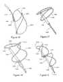
- FIG. 12shows an actuatable anchor design suitable for a shorter tissue shaping device.
- distal anchor 380is disposed distal to a connector 382 .
- anchor 380is formed in a figure eight configuration from flexible wire such as nitinol held by a crimp tube 384 .
- eyelets 386 and 387are formed in each of the anchor's proximal struts around the longitudinal axis of connector 382 . This arrangement reduces the radially outward force of the anchor. A distally directed actuation force on eyelets 386 and 387 move them over a lock hump 388 formed in connector 382 to actuate and lock anchor 380 .
- FIG. 12shows anchor 380 in an expanded configuration.
- an unexpanded configurationsuch as a configuration suitable for loading anchor 380 and the rest of the tissue shaping device into a catheter for initial deployment to treat mitral valve regurgitation
- eyelets 386 and 387are disposed proximal to lock bump 388 and the figure eight loops of anchor 380 are compressed against crimp 384 .
- bending points 390are formed in the distal struts of anchor 380 .
- bending points 390deform such that the upper arms 392 of the distal struts bend around bending points 390 and move toward the lower arms 394 of the distal struts, thereby limiting the distance eyelets 386 and 387 and the anchor's proximal struts must be moved proximally along the connector to compress the anchor.
- anchor 380would deform about bending points 390 to limit the cross-sectional profile of the anchor within the catheter, even if eyelets 386 and 387 were not moved proximally over lock bump 388 during the recapture procedure. Bending points may also be provided on the proximal anchor in a similar fashion.
- distal anchor 380may be part of a tissue shaping device having a proximal anchor and a connector disposed between the anchors.
- distal anchor 380may be deployed from a catheter and expanded with an actuation force to anchor against the coronary sinus wall to provide an anchoring force of at least one pound, preferably at least two pounds, and to lock anchor 380 in an expanded configuration.
- a proximally directed forceis applied to distal anchor 380 through. connector 382 , such as by moving the proximal anchor proximally about 1-6 cm., more preferably at least 2 cm., by pulling on a tether or control wire operated from outside the patient.
- the proximal anchormay then be deployed to maintain the reshaping force of the device.
- one aspect of anchor 380is its ability to conform and adapt to a variety of vessel sizes.
- the anchor's wire armsmay contact the coronary sinus wall before the eyelets 386 and 387 have been advance distally over lock bump 388 to lock the anchor in place. While continued distal advancement of eyelet 386 will create some outward force on the coronary sinus wall, much of the energy put into the anchor by the anchor actuation force will be absorbed by the deformation of the distal struts about bending points 390 .
- FIG. 13shows yet another embodiment of an actuatable anchor for use in a shorter tissue shaping device.
- Proximal anchor 1400is disposed proximal to a connector 1402 .
- anchor 1400is formed in a figure eight configuration from flexible wire such as nitinol held by a crimp tube 1404 .
- An eyelet 1406is formed around a lock bump 408 extending proximally from crimp 1404 .
- a distally directed actuation force on eyelet 406moves it over lock bump 1408 to actuate and lock anchor 400 .
- FIG. 13shows anchor 1400 in an expanded configuration.
- bending points 1410formed as loops in the anchor wire deform such that the upper arms 1412 of the distal struts bend around bending points 1410 and move toward the lower arms 1414 of the distal struts.
- proximal anchor 1400may be part of a tissue shaping device (such as that shown in FIGS. 8 and 9 ) having a distal anchor and a connector disposed between the anchors.
- one aspect of anchor 1400is its ability to conform and adapt to a variety of vessel sizes.
- the anchor's wire armsmay contact the coronary sinus wall before the eyelet 1406 has been advanced distally over lock hump 1408 to lock the anchor in place. While continued distal advancement of eyelet 1406 will create some outward force on the coronary sinus wall, much of the energy put into the anchor by the anchor actuation force will be absorbed by the deformation of the distal struts about bending points 1410 , which serve as expansion energy absorption elements and thereby limit the radially outward force on the coronary sinus wall.
- the looped bending points of the FIG. 13 embodimentmay he formed on the anchor's proximal struts in addition to or instead of on the distal struts.
- the looped bending point embodimentmay also be used in a distal anchor, as shown in FIG. 14 (without the crimp or connector). Note that in the embodiment of FIG. 14 the proximal and distal struts of anchor 1420 as well as the eyelet 1422 and bending points 1424 are formed from a single wire.
- FIG. 15shows an embodiment of a distal anchor 1440 similar to that of FIG. 8 suitable for use in a shorter tissue shaping device.
- extra twists 1442are added at the apex of the anchor's figure eight pattern.
- bending points 1444are formed in the anchor's distal struts.
- anchor 1440is actuatable by moving eyelet 1446 distally over a lock bump 1448 formed in connector 1450 .
- Anchor 1440may also be made as a self-expanding anchor by limiting or eliminating movement of the proximal struts of anchor 1440 along connector 1450 , as in the embodiment shown in FIG. 9 .
- the bending pointshelp anchor 1440 adapt and conform to different vessel sizes.
- the extra twists 1442also help the anchor adapt to different vessel diameters by keeping the anchor's apex together.
- anchor 1440is preferably harmed from nitinol wire.
- Anchor 1440may be used as part of a tissue shaping device.
- Anchor 1440may also be used as a proximal anchor.
- FIG. 16shows an embodiment of a distal anchor 1460 similar to that of FIG. 15 .
- the bending points 1462are formed in the anchor's proximal struts, as in the self-expanding anchor shown in FIG. 12 .
- extra twists 1464are added at the apex of the anchor's figure eight pattern.
- anchor 1460is actuatable by moving eyelet 1466 distally over a lock bump 1468 formed in connector 1470 .
- Anchor 1460may also be made as a self-expanding anchor by limiting or eliminating movement of the proximal connection point of anchor 1460 along connector 1470 , as in the embodiment shown in FIG. 9 .
- the bending pointshelp anchor 1460 adapt and conform to different vessel sizes.
- the extra twists 1464also help the anchor adapt to different vessel diameters by keeping the anchor's apex together.
- anchor 1460is preferably formed from nitinol wire.
- Anchor 1460may be used as part of a tissue shaping device in a manner similar to the anchor of FIG. 8 (for the actuatable anchor embodiment) or the anchor of FIG. 9 (for the self- expanding anchor embodiment).
- Anchor 1460may also be used as a proximal anchor.
- FIG. 17shows an embodiment of a self-expanding distal anchor 1480 suitable for use in a shorter tissue shaping device.
- anchor 1480is formed in a figure eight configuration from flexible wire such as nitinol held by a crimp tube 1482 .
- the base of the figure eight patternis narrower in this embodiment, however, with the anchor's proximal.
- struts 1484passing through crimp 1482 .
- Distal anchor 1480may be part of a tissue shaping device having a proximal anchor and a connector disposed between the anchors.
- distal anchor 1480may he deployed from a catheter and allowed to self-expand to anchor against the coronary sinus wall to provide an anchoring force of at least one pound, preferably at least two pounds.
- a proximally directed forceis applied to distal anchor 1480 through connector 1486 , such as by moving the proximal anchor proximally about 1-6 cm., more preferably at least 2 cm., by pulling on a tether or control wire operated from outside the patient.
- the proximal anchormay then be deployed to maintain the reshaping force of the device.
- FIG. 18shows an embodiment of a distal anchor suitable for use in a shorter tissue shaping device and similar to that of FIG. 8 .
- distal anchor 1500is disposed distal to a connector 1502 .
- anchor 1500is formed in a figure eight configuration from flexible wire such as nitinol held by a crimp tube 1504 .
- An eyelet 1506is formed around the longitudinal axis of connector 1502 .
- a distally directed actuation force on eyelet 1506moves it over a lock bump 1508 formed in connector 1502 to actuate and lock anchor 1500 .
- proximal struts 1501 and the angle of distal struts 1503are wider than corresponding angles in the FIG. 8 embodiment, however, causing anchor 1500 to distend more in width than in height when expanded, as shown.
- eyelet 1506is disposed proximal to lock bump 1508 and the figure eight loops of anchor 1500 are compressed against crimp 1504 .
- bending points 1510are formed in the distal struts 1503 , as in the FIG. 8 embodiment, to limit the width of the device in its unexpanded configuration within a catheter.
- Distal anchor 1500may be part of a tissue shaping device having a proximal anchor and a connector disposed between the anchors.
- distal anchor 1500may be deployed from a catheter and expanded with an actuation force to anchor against the coronary sinus wall to provide an anchoring force of at least one pound, preferably at least two pounds, and to lock anchor 1500 in an expanded configuration.
- a proximally directed forceis applied to distal anchor 1500 through connector 1502 , such as by moving the proximal anchor proximally about 1-6 cm., more preferably at least 2 cm., by pulling on a tether or control wire operated from outside the patient.
- the proximal anchormay then be deployed to maintain the reshaping force of the device.
- the anchor shown in FIG. 18may be used as a proximal anchor. This anchor may also be formed as a self-expanding anchor.
Landscapes
- Health & Medical Sciences (AREA)
- Cardiology (AREA)
- Heart & Thoracic Surgery (AREA)
- Transplantation (AREA)
- Engineering & Computer Science (AREA)
- Biomedical Technology (AREA)
- Oral & Maxillofacial Surgery (AREA)
- Vascular Medicine (AREA)
- Life Sciences & Earth Sciences (AREA)
- Animal Behavior & Ethology (AREA)
- General Health & Medical Sciences (AREA)
- Public Health (AREA)
- Veterinary Medicine (AREA)
- Prostheses (AREA)
- Surgical Instruments (AREA)
Abstract
Description
Claims (18)
Priority Applications (7)
| Application Number | Priority Date | Filing Date | Title |
|---|---|---|---|
| US15/368,467US10449048B2 (en) | 2003-12-19 | 2016-12-02 | Mitral valve annuloplasty device with twisted anchor |
| US15/639,426US9956077B2 (en) | 2003-12-19 | 2017-06-30 | Mitral valve annuloplasty device with twisted anchor |
| US15/967,112US10166102B2 (en) | 2003-12-19 | 2018-04-30 | Mitral valve annuloplasty device with twisted anchor |
| US16/568,055US11109971B2 (en) | 2003-12-19 | 2019-09-11 | Mitral valve annuloplasty device with twisted anchor |
| US16/573,903US11318016B2 (en) | 2003-12-19 | 2019-09-17 | Mitral valve annuloplasty device with twisted anchor |
| US17/466,706US11285005B2 (en) | 2006-07-17 | 2021-09-03 | Mitral valve annuloplasty device with twisted anchor |
| US17/655,974US12193936B2 (en) | 2006-07-17 | 2022-03-22 | Mitral valve annuloplasty device with twisted anchor |
Applications Claiming Priority (3)
| Application Number | Priority Date | Filing Date | Title |
|---|---|---|---|
| US10/742,585US20050137449A1 (en) | 2003-12-19 | 2003-12-19 | Tissue shaping device with self-expanding anchors |
| US11/458,040US9526616B2 (en) | 2003-12-19 | 2006-07-17 | Mitral valve annuloplasty device with twisted anchor |
| US15/368,467US10449048B2 (en) | 2003-12-19 | 2016-12-02 | Mitral valve annuloplasty device with twisted anchor |
Related Parent Applications (1)
| Application Number | Title | Priority Date | Filing Date |
|---|---|---|---|
| US11/458,040ContinuationUS9526616B2 (en) | 2003-12-19 | 2006-07-17 | Mitral valve annuloplasty device with twisted anchor |
Related Child Applications (3)
| Application Number | Title | Priority Date | Filing Date |
|---|---|---|---|
| US15/639,426ContinuationUS9956077B2 (en) | 2003-12-19 | 2017-06-30 | Mitral valve annuloplasty device with twisted anchor |
| US16/568,055ContinuationUS11109971B2 (en) | 2003-12-19 | 2019-09-11 | Mitral valve annuloplasty device with twisted anchor |
| US16/573,903ContinuationUS11318016B2 (en) | 2003-12-19 | 2019-09-17 | Mitral valve annuloplasty device with twisted anchor |
Publications (2)
| Publication Number | Publication Date |
|---|---|
| US20170079796A1 US20170079796A1 (en) | 2017-03-23 |
| US10449048B2true US10449048B2 (en) | 2019-10-22 |
Family
ID=46324803
Family Applications (6)
| Application Number | Title | Priority Date | Filing Date |
|---|---|---|---|
| US11/458,040Expired - Fee RelatedUS9526616B2 (en) | 2003-12-19 | 2006-07-17 | Mitral valve annuloplasty device with twisted anchor |
| US15/368,467Expired - LifetimeUS10449048B2 (en) | 2003-12-19 | 2016-12-02 | Mitral valve annuloplasty device with twisted anchor |
| US15/639,426ActiveUS9956077B2 (en) | 2003-12-19 | 2017-06-30 | Mitral valve annuloplasty device with twisted anchor |
| US15/967,112ActiveUS10166102B2 (en) | 2003-12-19 | 2018-04-30 | Mitral valve annuloplasty device with twisted anchor |
| US16/568,055Active2027-02-24US11109971B2 (en) | 2003-12-19 | 2019-09-11 | Mitral valve annuloplasty device with twisted anchor |
| US16/573,903Expired - LifetimeUS11318016B2 (en) | 2003-12-19 | 2019-09-17 | Mitral valve annuloplasty device with twisted anchor |
Family Applications Before (1)
| Application Number | Title | Priority Date | Filing Date |
|---|---|---|---|
| US11/458,040Expired - Fee RelatedUS9526616B2 (en) | 2003-12-19 | 2006-07-17 | Mitral valve annuloplasty device with twisted anchor |
Family Applications After (4)
| Application Number | Title | Priority Date | Filing Date |
|---|---|---|---|
| US15/639,426ActiveUS9956077B2 (en) | 2003-12-19 | 2017-06-30 | Mitral valve annuloplasty device with twisted anchor |
| US15/967,112ActiveUS10166102B2 (en) | 2003-12-19 | 2018-04-30 | Mitral valve annuloplasty device with twisted anchor |
| US16/568,055Active2027-02-24US11109971B2 (en) | 2003-12-19 | 2019-09-11 | Mitral valve annuloplasty device with twisted anchor |
| US16/573,903Expired - LifetimeUS11318016B2 (en) | 2003-12-19 | 2019-09-17 | Mitral valve annuloplasty device with twisted anchor |
Country Status (1)
| Country | Link |
|---|---|
| US (6) | US9526616B2 (en) |
Cited By (6)
| Publication number | Priority date | Publication date | Assignee | Title |
|---|---|---|---|---|
| US11109971B2 (en) | 2003-12-19 | 2021-09-07 | Cardiac Dimensions Pty. Ltd. | Mitral valve annuloplasty device with twisted anchor |
| US11285005B2 (en) | 2006-07-17 | 2022-03-29 | Cardiac Dimensions Pty. Ltd. | Mitral valve annuloplasty device with twisted anchor |
| US11311380B2 (en) | 2003-05-02 | 2022-04-26 | Cardiac Dimensions Pty. Ltd. | Device and method for modifying the shape of a body organ |
| US11399939B2 (en) | 2017-03-08 | 2022-08-02 | Cardiac Dimensions Pty. Ltd. | Methods and devices for reducing paravalvular leakage |
| US11596771B2 (en) | 2020-12-14 | 2023-03-07 | Cardiac Dimensions Pty. Ltd. | Modular pre-loaded medical implants and delivery systems |
| US12016538B2 (en) | 2005-01-20 | 2024-06-25 | Cardiac Dimensions Pty. Ltd. | Tissue shaping device |
Families Citing this family (27)
| Publication number | Priority date | Publication date | Assignee | Title |
|---|---|---|---|---|
| US7635387B2 (en) | 2001-11-01 | 2009-12-22 | Cardiac Dimensions, Inc. | Adjustable height focal tissue deflector |
| US6824562B2 (en) | 2002-05-08 | 2004-11-30 | Cardiac Dimensions, Inc. | Body lumen device anchor, device and assembly |
| US6793673B2 (en) | 2002-12-26 | 2004-09-21 | Cardiac Dimensions, Inc. | System and method to effect mitral valve annulus of a heart |
| US6976995B2 (en) | 2002-01-30 | 2005-12-20 | Cardiac Dimensions, Inc. | Fixed length anchor and pull mitral valve device and method |
| US7179282B2 (en) | 2001-12-05 | 2007-02-20 | Cardiac Dimensions, Inc. | Device and method for modifying the shape of a body organ |
| CA2877641C (en) | 2002-05-08 | 2017-01-17 | Cardiac Dimensions Pty. Ltd. | Device and method for modifying the shape of a body organ |
| US7316708B2 (en) | 2002-12-05 | 2008-01-08 | Cardiac Dimensions, Inc. | Medical device delivery system |
| US7837729B2 (en) | 2002-12-05 | 2010-11-23 | Cardiac Dimensions, Inc. | Percutaneous mitral valve annuloplasty delivery system |
| US7314485B2 (en) | 2003-02-03 | 2008-01-01 | Cardiac Dimensions, Inc. | Mitral valve device using conditioned shape memory alloy |
| US7351259B2 (en) | 2003-06-05 | 2008-04-01 | Cardiac Dimensions, Inc. | Device, system and method to affect the mitral valve annulus of a heart |
| US7887582B2 (en) | 2003-06-05 | 2011-02-15 | Cardiac Dimensions, Inc. | Device and method for modifying the shape of a body organ |
| US7794496B2 (en) | 2003-12-19 | 2010-09-14 | Cardiac Dimensions, Inc. | Tissue shaping device with integral connector and crimp |
| US8608797B2 (en)* | 2005-03-17 | 2013-12-17 | Valtech Cardio Ltd. | Mitral valve treatment techniques |
| US7503932B2 (en)* | 2006-04-11 | 2009-03-17 | Cardiac Dimensions, Inc. | Mitral valve annuloplasty device with vena cava anchor |
| FR2930137B1 (en)* | 2008-04-18 | 2010-04-23 | Corevalve Inc | TREATMENT EQUIPMENT FOR A CARDIAC VALVE, IN PARTICULAR A MITRAL VALVE. |
| US8006594B2 (en) | 2008-08-11 | 2011-08-30 | Cardiac Dimensions, Inc. | Catheter cutting tool |
| US9307980B2 (en)* | 2010-01-22 | 2016-04-12 | 4Tech Inc. | Tricuspid valve repair using tension |
| CA2793839C (en)* | 2010-03-23 | 2018-05-22 | Boston Scientific Scimed, Inc. | Annuloplasty device |
| US8747462B2 (en) | 2011-05-17 | 2014-06-10 | Boston Scientific Scimed, Inc. | Corkscrew annuloplasty device |
| WO2012158258A1 (en) | 2011-05-17 | 2012-11-22 | Boston Scientific Scimed, Inc. | Annuloplasty ring with piercing wire and segmented wire lumen |
| EP2709559B1 (en) | 2011-05-17 | 2015-01-21 | Boston Scientific Scimed, Inc. | Annuloplasty ring with anchors fixed by curing polymer |
| US9907547B2 (en) | 2014-12-02 | 2018-03-06 | 4Tech Inc. | Off-center tissue anchors |
| US10363138B2 (en)* | 2016-11-09 | 2019-07-30 | Evalve, Inc. | Devices for adjusting the curvature of cardiac valve structures |
| EP3648678A4 (en) | 2017-07-06 | 2021-03-24 | Raghuveer Basude | TISSUE GRIPPING DEVICES AND RELATED PROCEDURES |
| US11285003B2 (en) | 2018-03-20 | 2022-03-29 | Medtronic Vascular, Inc. | Prolapse prevention device and methods of use thereof |
| US11026791B2 (en) | 2018-03-20 | 2021-06-08 | Medtronic Vascular, Inc. | Flexible canopy valve repair systems and methods of use |
| CN115737201A (en)* | 2021-09-03 | 2023-03-07 | 瀚芯医疗科技(深圳)有限公司 | Mitral annulus contracting device |
Citations (243)
| Publication number | Priority date | Publication date | Assignee | Title |
|---|---|---|---|---|
| GB741604A (en) | 1952-10-16 | 1955-12-07 | S & R J Everett & Co Ltd | Improvements relating to hypodermic syringes |
| US3620212A (en) | 1970-06-15 | 1971-11-16 | Robert D Fannon Jr | Intrauterine contraceptive device |
| US3786806A (en) | 1972-11-22 | 1974-01-22 | A Johnson | Thermoconstrictive surgical appliance |
| US3890977A (en) | 1974-03-01 | 1975-06-24 | Bruce C Wilson | Kinetic memory electrodes, catheters and cannulae |
| US3974526A (en) | 1973-07-06 | 1976-08-17 | Dardik Irving I | Vascular prostheses and process for producing the same |
| US3995623A (en) | 1974-12-23 | 1976-12-07 | American Hospital Supply Corporation | Multipurpose flow-directed catheter |
| US4055861A (en) | 1975-04-11 | 1977-11-01 | Rhone-Poulenc Industries | Support for a natural human heart valve |
| US4164046A (en) | 1977-05-16 | 1979-08-14 | Cooley Denton | Valve prosthesis |
| US4485816A (en) | 1981-06-25 | 1984-12-04 | Alchemia | Shape-memory surgical staple apparatus and method for use in surgical suturing |
| US4550870A (en) | 1983-10-13 | 1985-11-05 | Alchemia Ltd. Partnership | Stapling device |
| US4588395A (en) | 1978-03-10 | 1986-05-13 | Lemelson Jerome H | Catheter and method |
| US4830023A (en) | 1987-11-27 | 1989-05-16 | Medi-Tech, Incorporated | Medical guidewire |
| US5061277A (en) | 1986-08-06 | 1991-10-29 | Baxter International Inc. | Flexible cardiac valvular support prosthesis |
| US5099838A (en) | 1988-12-15 | 1992-03-31 | Medtronic, Inc. | Endocardial defibrillation electrode system |
| US5104404A (en) | 1989-10-02 | 1992-04-14 | Medtronic, Inc. | Articulated stent |
| US5197978A (en) | 1991-04-26 | 1993-03-30 | Advanced Coronary Technology, Inc. | Removable heat-recoverable tissue supporting device |
| US5250071A (en) | 1992-09-22 | 1993-10-05 | Target Therapeutics, Inc. | Detachable embolic coil assembly using interlocking clasps and method of use |
| US5261916A (en) | 1991-12-12 | 1993-11-16 | Target Therapeutics | Detachable pusher-vasoocclusive coil assembly with interlocking ball and keyway coupling |
| US5265601A (en) | 1992-05-01 | 1993-11-30 | Medtronic, Inc. | Dual chamber cardiac pacing from a single electrode |
| US5344426A (en) | 1990-04-25 | 1994-09-06 | Advanced Cardiovascular Systems, Inc. | Method and system for stent delivery |
| US5350420A (en) | 1989-07-31 | 1994-09-27 | Baxter International Inc. | Flexible annuloplasty ring and holder |
| US5411549A (en) | 1993-07-13 | 1995-05-02 | Scimed Life Systems, Inc. | Selectively expandable, retractable and removable stent |
| US5433727A (en) | 1994-08-16 | 1995-07-18 | Sideris; Eleftherios B. | Centering buttoned device for the occlusion of large defects for occluding |
| US5441515A (en) | 1993-04-23 | 1995-08-15 | Advanced Cardiovascular Systems, Inc. | Ratcheting stent |
| US5449373A (en) | 1994-03-17 | 1995-09-12 | Medinol Ltd. | Articulated stent |
| US5454365A (en) | 1990-11-05 | 1995-10-03 | Bonutti; Peter M. | Mechanically expandable arthroscopic retractors |
| US5458615A (en) | 1993-07-06 | 1995-10-17 | Advanced Cardiovascular Systems, Inc. | Stent delivery system |
| US5474557A (en) | 1993-09-21 | 1995-12-12 | Mai; Christian | Multibranch osteosynthesis clip with dynamic compression and self-retention |
| US5507802A (en) | 1993-06-02 | 1996-04-16 | Cardiac Pathways Corporation | Method of mapping and/or ablation using a catheter having a tip with fixation means |
| US5507295A (en) | 1992-07-01 | 1996-04-16 | British Technology Group Limited | Medical devices |
| US5514161A (en) | 1994-04-05 | 1996-05-07 | Ela Medical S.A. | Methods and apparatus for controlling atrial stimulation in a double atrial triple chamber cardiac pacemaker |
| US5554177A (en) | 1995-03-27 | 1996-09-10 | Medtronic, Inc. | Method and apparatus to optimize pacing based on intensity of acoustic signal |
| US5562698A (en) | 1994-03-09 | 1996-10-08 | Cook Incorporated | Intravascular treatment system |
| US5575818A (en) | 1995-02-14 | 1996-11-19 | Corvita Corporation | Endovascular stent with locking ring |
| US5584867A (en) | 1994-04-05 | 1996-12-17 | Ela Medical S.A. | Method and apparatus for controlling a double atrial triple chamber cardiac pacemaker having a fallback mode |
| US5601600A (en) | 1995-09-08 | 1997-02-11 | Conceptus, Inc. | Endoluminal coil delivery system having a mechanical release mechanism |
| US5617854A (en) | 1994-06-22 | 1997-04-08 | Munsif; Anand | Shaped catheter device and method |
| US5662703A (en) | 1995-04-14 | 1997-09-02 | Schneider (Usa) Inc. | Rolling membrane stent delivery device |
| US5676671A (en) | 1995-04-12 | 1997-10-14 | Inoue; Kanji | Device for introducing an appliance to be implanted into a catheter |
| US5733328A (en) | 1994-11-07 | 1998-03-31 | Scimed Life Systems, Inc. | Expandable stent using sliding members |
| US5733325A (en) | 1993-11-04 | 1998-03-31 | C. R. Bard, Inc. | Non-migrating vascular prosthesis and minimally invasive placement system |
| US5741297A (en) | 1996-08-28 | 1998-04-21 | Simon; Morris | Daisy occluder and method for septal defect repair |
| US5752969A (en) | 1993-06-17 | 1998-05-19 | Sofamor S.N.C. | Instrument for the surgical treatment of an intervertebral disc by the anterior route |
| JP2754067B2 (en) | 1989-01-17 | 1998-05-20 | 日本ゼオン株式会社 | Medical body wall hole plugging jig |
| US5800519A (en) | 1994-04-29 | 1998-09-01 | Kopin Corporation | Tubular medical prosthesis for use in a body lumen |
| US5824071A (en) | 1996-09-16 | 1998-10-20 | Circulation, Inc. | Apparatus for treatment of ischemic heart disease by providing transvenous myocardial perfusion |
| US5836882A (en) | 1997-03-17 | 1998-11-17 | Frazin; Leon J. | Method and apparatus of localizing an insertion end of a probe within a biotic structure |
| WO1998056435A1 (en) | 1997-06-13 | 1998-12-17 | Micro Therapeutics, Inc. | Contoured syringe and novel luer hub and methods for embolizing blood vessels |
| EP0893133A1 (en) | 1997-07-24 | 1999-01-27 | Medex | Medical liquid injection device, syringe for use with the device and method of engaging the syringe |
| US5871501A (en) | 1994-01-18 | 1999-02-16 | Datascope Investment Corp. | Guide wire with releasable barb anchor |
| EP0903110A1 (en) | 1997-09-12 | 1999-03-24 | B. Braun Medical Inc. | Introducer for an expandable vascular occlusion device |
| US5895391A (en) | 1996-09-27 | 1999-04-20 | Target Therapeutics, Inc. | Ball lock joint and introducer for vaso-occlusive member |
| US5899882A (en) | 1994-10-27 | 1999-05-04 | Novoste Corporation | Catheter apparatus for radiation treatment of a desired area in the vascular system of a patient |
| US5908404A (en) | 1996-05-13 | 1999-06-01 | Elliott; James B. | Methods for inserting an implant |
| US5928258A (en) | 1997-09-26 | 1999-07-27 | Corvita Corporation | Method and apparatus for loading a stent or stent-graft into a delivery sheath |
| US5954761A (en) | 1997-03-25 | 1999-09-21 | Intermedics Inc. | Implantable endocardial lead assembly having a stent |
| US5961545A (en) | 1997-01-17 | 1999-10-05 | Meadox Medicals, Inc. | EPTFE graft-stent composite device |
| US5978705A (en) | 1997-03-14 | 1999-11-02 | Uab Research Foundation | Method and apparatus for treating cardiac arrhythmia using auxiliary pulse |
| US6001118A (en) | 1997-03-06 | 1999-12-14 | Scimed Life Systems, Inc. | Distal protection device and method |
| US6007519A (en) | 1997-07-30 | 1999-12-28 | Rosselli; Matteo | Central access cannulation device |
| EP0968688A1 (en) | 1998-07-03 | 2000-01-05 | Cordis Europa N.V. | Improved vascular filter for controlled release |
| US6015402A (en) | 1997-03-07 | 2000-01-18 | Sahota; Harvinder | Wire perfusion catheter |
| US6022371A (en) | 1996-10-22 | 2000-02-08 | Scimed Life Systems, Inc. | Locking stent |
| US6027517A (en) | 1994-02-24 | 2000-02-22 | Radiance Medical Systems, Inc. | Fixed focal balloon for interactive angioplasty and stent implantation catheter with focalized balloon |
| US6045497A (en) | 1997-01-02 | 2000-04-04 | Myocor, Inc. | Heart wall tension reduction apparatus and method |
| US6053900A (en) | 1996-02-16 | 2000-04-25 | Brown; Joe E. | Apparatus and method for delivering diagnostic and therapeutic agents intravascularly |
| US6056775A (en) | 1996-05-31 | 2000-05-02 | Ave Galway Limited | Bifurcated endovascular stents and method and apparatus for their placement |
| US6077295A (en) | 1996-07-15 | 2000-06-20 | Advanced Cardiovascular Systems, Inc. | Self-expanding stent delivery system |
| US6080182A (en) | 1996-12-20 | 2000-06-27 | Gore Enterprise Holdings, Inc. | Self-expanding defect closure device and method of making and using |
| US6086611A (en) | 1997-09-25 | 2000-07-11 | Ave Connaught | Bifurcated stent |
| US6096064A (en) | 1997-09-19 | 2000-08-01 | Intermedics Inc. | Four chamber pacer for dilated cardiomyopthy |
| WO2000044313A1 (en) | 1999-01-27 | 2000-08-03 | Viacor Incorporated | Cardiac valve procedure methods and devices |
| US6099552A (en) | 1997-11-12 | 2000-08-08 | Boston Scientific Corporation | Gastrointestinal copression clips |
| US6129755A (en) | 1998-01-09 | 2000-10-10 | Nitinol Development Corporation | Intravascular stent having an improved strut configuration |
| WO2000060995A2 (en) | 1999-04-09 | 2000-10-19 | Evalve, Inc. | Methods and apparatus for cardiac valve repair |
| JP2000308652A (en) | 1999-03-09 | 2000-11-07 | Jostra Medizintechnik Ag | Loop forming artificial organ |
| EP1050274A1 (en) | 1998-11-20 | 2000-11-08 | Medical Industries Corporation | Hemostatic agent inserting device |
| US6159220A (en) | 1999-03-11 | 2000-12-12 | Scimed Life Systems, Inc. | Medical retrieval device |
| WO2000074603A1 (en) | 1999-06-08 | 2000-12-14 | S & A Rings, Llc | Annuloplasty rings for heart valve replacement and repair |
| US6162168A (en) | 1997-01-02 | 2000-12-19 | Myocor, Inc. | Heart wall tension reduction apparatus |
| SE9902455L (en) | 1999-06-29 | 2000-12-30 | Jan Otto Solem | Apparatus for treating lack of closure of the mitral valve apparatus |
| US6171320B1 (en) | 1996-12-25 | 2001-01-09 | Niti Alloys Technologies Ltd. | Surgical clip |
| US6183512B1 (en) | 1999-04-16 | 2001-02-06 | Edwards Lifesciences Corporation | Flexible annuloplasty system |
| US6190406B1 (en) | 1998-01-09 | 2001-02-20 | Nitinal Development Corporation | Intravascular stent having tapered struts |
| US6200336B1 (en) | 1998-06-02 | 2001-03-13 | Cook Incorporated | Multiple-sided intraluminal medical device |
| WO2001019292A1 (en) | 1999-09-17 | 2001-03-22 | Cardiac Concepts, Inc. | Mitral valve annuloplasty ring and method |
| EP1095634A2 (en) | 1999-10-27 | 2001-05-02 | Cordis Corporation | Rapid exchange self-expanding stent delivery catheter system |
| US6228098B1 (en) | 1998-07-10 | 2001-05-08 | General Surgical Innovations, Inc. | Apparatus and method for surgical fastening |
| US6241757B1 (en) | 1997-02-04 | 2001-06-05 | Solco Surgical Instrument Co., Ltd. | Stent for expanding body's lumen |
| US6254628B1 (en) | 1996-12-09 | 2001-07-03 | Micro Therapeutics, Inc. | Intracranial stent |
| WO2001050985A1 (en) | 2000-01-14 | 2001-07-19 | Viacor Incorporated | Tissue annuloplasty band and apparatus and method for fashioning, sizing and implanting the same |
| US6267783B1 (en) | 1998-11-09 | 2001-07-31 | Cordis Corporation | Stent which is easily recaptured and repositioned within the body |
| WO2001054618A1 (en) | 2000-01-31 | 2001-08-02 | Mitralife | Percutaneous mitral annuloplasty and cardiac reinforcement |
| US6275730B1 (en) | 1997-03-14 | 2001-08-14 | Uab Research Foundation | Method and apparatus for treating cardiac arrythmia |
| US20010018611A1 (en) | 1999-06-30 | 2001-08-30 | Solem Jan Otto | Method and device for treatment of mitral insufficiency |
| US6306141B1 (en) | 1983-10-14 | 2001-10-23 | Medtronic, Inc. | Medical devices incorporating SIM alloy elements |
| US6312446B1 (en) | 1996-03-22 | 2001-11-06 | Scimed Life Systems, Inc. | Apparatus and method for closing a septal defect |
| US20010041899A1 (en) | 1998-03-27 | 2001-11-15 | James B. Hunt | Minimally-invasive medical retrieval device |
| WO2001087180A2 (en) | 2000-05-17 | 2001-11-22 | Xtent Medical Inc | Selectively expandable and releasable stent |
| US6334864B1 (en) | 2000-05-17 | 2002-01-01 | Aga Medical Corp. | Alignment member for delivering a non-symmetric device with a predefined orientation |
| WO2002000099A2 (en) | 2000-06-23 | 2002-01-03 | Viacor Incorporated | Automated annular plication for mitral valve repair |
| WO2002001999A2 (en) | 2000-06-30 | 2002-01-10 | Viacor, Incorporated | Method and apparatus for performing a procedure on a cardiac valve |
| WO2002005888A1 (en) | 2000-06-30 | 2002-01-24 | Viacor Incorporated | Intravascular filter with debris entrapment mechanism |
| US6342067B1 (en) | 1998-01-09 | 2002-01-29 | Nitinol Development Corporation | Intravascular stent having curved bridges for connecting adjacent hoops |
| US6345198B1 (en) | 1998-01-23 | 2002-02-05 | Pacesetter, Inc. | Implantable stimulation system for providing dual bipolar sensing using an electrode positioned in proximity to the tricuspid valve and programmable polarity |
| EP1177779A2 (en) | 2000-07-31 | 2002-02-06 | Mani, Inc. | Stent and method of manufacturing |
| US6352553B1 (en) | 1995-12-14 | 2002-03-05 | Gore Enterprise Holdings, Inc. | Stent-graft deployment apparatus and method |
| US6352561B1 (en) | 1996-12-23 | 2002-03-05 | W. L. Gore & Associates | Implant deployment apparatus |
| WO2002019951A1 (en) | 2000-09-07 | 2002-03-14 | Viacor, Inc. | Fixation band for affixing a prosthetic heart valve to tissue |
| US6358195B1 (en) | 2000-03-09 | 2002-03-19 | Neoseed Technology Llc | Method and apparatus for loading radioactive seeds into brachytherapy needles |
| US6368345B1 (en) | 1998-09-30 | 2002-04-09 | Edwards Lifesciences Corporation | Methods and apparatus for intraluminal placement of a bifurcated intraluminal garafat |
| WO2002034118A2 (en) | 2000-10-27 | 2002-05-02 | Viacor, Inc. | Intracardiovascular access (icvatm) system |
| US6395017B1 (en) | 1996-11-15 | 2002-05-28 | C. R. Bard, Inc. | Endoprosthesis delivery catheter with sequential stage control |
| US20020065554A1 (en) | 2000-10-25 | 2002-05-30 | Streeter Richard B. | Mitral shield |
| WO2002047539A2 (en) | 2000-12-15 | 2002-06-20 | Viacor, Inc. | Apparatus and method for replacing aortic valve |
| US6409750B1 (en) | 1999-02-01 | 2002-06-25 | Board Of Regents, The University Of Texas System | Woven bifurcated and trifurcated stents and methods for making the same |
| WO2002053206A2 (en) | 2000-12-28 | 2002-07-11 | Cardiac Dimensions, Inc. | Mitral valve constricting device, system and method |
| US6419696B1 (en) | 2000-07-06 | 2002-07-16 | Paul A. Spence | Annuloplasty devices and related heart valve repair methods |
| US20020095167A1 (en) | 2000-10-23 | 2002-07-18 | Liddicoat John R. | Automated annular plication for mitral valve repair |
| WO2002060352A1 (en) | 2001-01-30 | 2002-08-08 | Ev3 Santa Rosa, Inc. | Medical system and method for remodeling an extravascular tissue structure |
| WO2002062408A2 (en) | 2001-02-05 | 2002-08-15 | Viacor, Inc. | Method and apparatus for improving mitral valve function |
| WO2002062263A2 (en) | 2001-02-05 | 2002-08-15 | Viacor, Inc. | Apparatus and method for reducing mitral regurgitation |
| US6442427B1 (en) | 2000-04-27 | 2002-08-27 | Medtronic, Inc. | Method and system for stimulating a mammalian heart |
| WO2002076284A2 (en) | 2001-03-23 | 2002-10-03 | Viacor, Inc. | Method and apparatus for reducing mitral regurgitation |
| WO2002078576A2 (en) | 2001-03-29 | 2002-10-10 | Viacor, Inc. | Method and apparatus for improving mitral valve function |
| US6464720B2 (en) | 1997-09-24 | 2002-10-15 | Cook Incorporated | Radially expandable stent |
| US20020151961A1 (en) | 2000-01-31 | 2002-10-17 | Lashinski Randall T. | Medical system and method for remodeling an extravascular tissue structure |
| US20020156526A1 (en) | 2001-04-24 | 2002-10-24 | Hlavka Edwin J. | Method and apparatus for catheter-based annuloplasty |
| US20020161377A1 (en) | 2001-04-27 | 2002-10-31 | Dmitry Rabkin | Apparatus for delivering, repositioning and/or retrieving self-expanding stents |
| US20020161393A1 (en) | 1999-07-30 | 2002-10-31 | Demond Jackson F. | Vascular device for emboli and thrombi removal and methods of use |
| US6478776B1 (en) | 2000-04-05 | 2002-11-12 | Biocardia, Inc. | Implant delivery catheter system and methods for its use |
| US20020183837A1 (en) | 2001-03-05 | 2002-12-05 | Streeter Richard B. | Apparatus and method for reducing mitral regurgitation |
| US20020183838A1 (en) | 2001-03-29 | 2002-12-05 | Liddicoat John R. | Method and apparatus for improving mitral valve function |
| US20020188170A1 (en) | 2001-04-27 | 2002-12-12 | Santamore William P. | Prevention of myocardial infarction induced ventricular expansion and remodeling |
| US20020193827A1 (en) | 2001-06-18 | 2002-12-19 | Rex Medical | Removable vein filter |
| US6503271B2 (en) | 1998-01-09 | 2003-01-07 | Cordis Corporation | Intravascular device with improved radiopacity |
| US20030018358A1 (en) | 1999-06-25 | 2003-01-23 | Vahid Saadat | Apparatus and methods for treating tissue |
| US20030040771A1 (en) | 1999-02-01 | 2003-02-27 | Hideki Hyodoh | Methods for creating woven devices |
| US20030078654A1 (en) | 2001-08-14 | 2003-04-24 | Taylor Daniel C. | Method and apparatus for improving mitral valve function |
| US20030078465A1 (en) | 2001-10-16 | 2003-04-24 | Suresh Pai | Systems for heart treatment |
| US6556873B1 (en) | 1999-11-29 | 2003-04-29 | Medtronic, Inc. | Medical electrical lead having variable bending stiffness |
| US20030083613A1 (en) | 1999-05-11 | 2003-05-01 | Schaer Alan K. | Catheter positioning system |
| US20030088305A1 (en) | 2001-10-26 | 2003-05-08 | Cook Incorporated | Prostheses for curved lumens |
| WO2003037171A2 (en) | 2001-11-01 | 2003-05-08 | Cardiac Dimensions, Inc. | Focused compression mitral valve device and method |
| US6562067B2 (en) | 2001-06-08 | 2003-05-13 | Cordis Corporation | Stent with interlocking elements |
| US6562066B1 (en) | 2001-03-02 | 2003-05-13 | Eric C. Martin | Stent for arterialization of the coronary sinus and retrograde perfusion of the myocardium |
| US20030093148A1 (en) | 2001-11-13 | 2003-05-15 | Bolling Steven F. | Mitral valve annuloplasty ring for molding left ventricle geometry |
| US6569198B1 (en) | 2000-03-31 | 2003-05-27 | Richard A. Wilson | Mitral or tricuspid valve annuloplasty prosthetic device |
| WO2003049648A2 (en) | 2001-12-05 | 2003-06-19 | Cardiac Dimensions, Inc. | Anchor and pull mitral valve device and method |
| WO2003049647A1 (en) | 2001-12-11 | 2003-06-19 | Bentley Surgical Gmbh | Implant for treatment of the insufficiency of a cardiac valve |
| US6589208B2 (en) | 2000-06-20 | 2003-07-08 | Applied Medical Resources Corporation | Self-deploying catheter assembly |
| WO2003055417A1 (en) | 2001-12-28 | 2003-07-10 | Edwards Lifesciences Ag | Delayed memory device |
| US20030130730A1 (en) | 2001-10-26 | 2003-07-10 | Cohn William E. | Method and apparatus for reducing mitral regurgitation |
| US20030135267A1 (en) | 2002-01-11 | 2003-07-17 | Solem Jan Otto | Delayed memory device |
| US6602288B1 (en) | 2000-10-05 | 2003-08-05 | Edwards Lifesciences Corporation | Minimally-invasive annuloplasty repair segment delivery template, system and method of use |
| WO2003063735A2 (en) | 2002-01-30 | 2003-08-07 | Cardiac Dimensions, Inc. | Fixed length anchor and pull mitral valve device and method |
| US6623521B2 (en) | 1998-02-17 | 2003-09-23 | Md3, Inc. | Expandable stent with sliding and locking radial elements |
| US6629994B2 (en) | 2001-06-11 | 2003-10-07 | Advanced Cardiovascular Systems, Inc. | Intravascular stent |
| US6643546B2 (en) | 2001-02-13 | 2003-11-04 | Quetzal Biomedical, Inc. | Multi-electrode apparatus and method for treatment of congestive heart failure |
| US6648881B2 (en) | 1999-04-19 | 2003-11-18 | Cardiac Pacemakers, Inc. | Method for reducing arterial restenosis in the presence of an intravascular stent |
| US6676702B2 (en) | 2001-05-14 | 2004-01-13 | Cardiac Dimensions, Inc. | Mitral valve therapy assembly and method |
| US6689164B1 (en) | 1999-10-12 | 2004-02-10 | Jacques Seguin | Annuloplasty device for use in minimally invasive procedure |
| US20040039443A1 (en) | 1999-06-30 | 2004-02-26 | Solem Jan Otto | Method and device for treatment of mitral insufficiency |
| US6709425B2 (en) | 1998-09-30 | 2004-03-23 | C. R. Bard, Inc. | Vascular inducing implants |
| US6716158B2 (en) | 2001-09-07 | 2004-04-06 | Mardil, Inc. | Method and apparatus for external stabilization of the heart |
| US6721598B1 (en) | 2001-08-31 | 2004-04-13 | Pacesetter, Inc. | Coronary sinus cardiac lead for stimulating and sensing in the right and left heart and system |
| US20040073302A1 (en) | 2002-02-05 | 2004-04-15 | Jonathan Rourke | Method and apparatus for improving mitral valve function |
| US6723038B1 (en) | 2000-10-06 | 2004-04-20 | Myocor, Inc. | Methods and devices for improving mitral valve function |
| US6733521B2 (en) | 2001-04-11 | 2004-05-11 | Trivascular, Inc. | Delivery system and method for endovascular graft |
| US20040098116A1 (en) | 2002-11-15 | 2004-05-20 | Callas Peter L. | Valve annulus constriction apparatus and method |
| US6743219B1 (en) | 2000-08-02 | 2004-06-01 | Cordis Corporation | Delivery apparatus for a self-expanding stent |
| WO2004045463A2 (en) | 2002-11-15 | 2004-06-03 | Advanced Cardiovascular Systems, Inc. | Apparatuses and methods for hart valve repair |
| US20040127982A1 (en) | 2002-10-01 | 2004-07-01 | Ample Medical, Inc. | Devices, systems, and methods for reshaping a heart valve annulus |
| US20040133220A1 (en) | 2000-01-31 | 2004-07-08 | Randall Lashinski | Adjustable transluminal annuloplasty system |
| US20040133240A1 (en) | 2003-01-07 | 2004-07-08 | Cardiac Dimensions, Inc. | Electrotherapy system, device, and method for treatment of cardiac valve dysfunction |
| US6764510B2 (en) | 2002-01-09 | 2004-07-20 | Myocor, Inc. | Devices and methods for heart valve treatment |
| US20040148020A1 (en) | 2002-11-12 | 2004-07-29 | Vidlund Robert M. | Devices and methods for heart valve treatment |
| US20040148021A1 (en) | 2002-08-29 | 2004-07-29 | Cartledge Richard G. | Implantable devices for controlling the internal circumference of an anatomic orifice or lumen |
| US20040148019A1 (en) | 2002-11-12 | 2004-07-29 | Vidlund Robert M. | Devices and methods for heart valve treatment |
| US20040153147A1 (en) | 2003-02-03 | 2004-08-05 | Cardiac Dimensions, Inc. | Mitral valve device using conditioned shape memory alloy |
| US20040158321A1 (en) | 2003-02-12 | 2004-08-12 | Cardiac Dimensions, Inc. | Method of implanting a mitral valve therapy device |
| US6776784B2 (en) | 2001-09-06 | 2004-08-17 | Core Medical, Inc. | Clip apparatus for closing septal defects and methods of use |
| US6793673B2 (en) | 2002-12-26 | 2004-09-21 | Cardiac Dimensions, Inc. | System and method to effect mitral valve annulus of a heart |
| US6798231B2 (en) | 2001-03-05 | 2004-09-28 | Ishiwawajima-Harima Heavy Industries Co., Ltd. & Sharp Kabushiki Kaisha | Inspection device for liquid crystal driving substrate |
| US6797001B2 (en) | 2002-03-11 | 2004-09-28 | Cardiac Dimensions, Inc. | Device, assembly and method for mitral valve repair |
| US20040193191A1 (en) | 2003-02-06 | 2004-09-30 | Guided Delivery Systems, Inc. | Devices and methods for heart valve repair |
| US6800090B2 (en) | 2001-05-14 | 2004-10-05 | Cardiac Dimensions, Inc. | Mitral valve therapy device, system and method |
| WO2004084746A2 (en) | 2003-03-26 | 2004-10-07 | Reitan Oeyvind M D | Device for treatment of an insufficiency of a heart valve |
| US6805128B1 (en) | 1996-10-22 | 2004-10-19 | Epicor Medical, Inc. | Apparatus and method for ablating tissue |
| US6810882B2 (en) | 2001-01-30 | 2004-11-02 | Ev3 Santa Rosa, Inc. | Transluminal mitral annuloplasty |
| US20040220654A1 (en) | 2003-05-02 | 2004-11-04 | Cardiac Dimensions, Inc. | Device and method for modifying the shape of a body organ |
| US20040220657A1 (en) | 2003-05-02 | 2004-11-04 | Cardiac Dimensions, Inc., A Washington Corporation | Tissue shaping device with conformable anchors |
| US6821297B2 (en) | 2000-02-02 | 2004-11-23 | Robert V. Snyders | Artificial heart valve, implantation instrument and method therefor |
| US6824562B2 (en) | 2002-05-08 | 2004-11-30 | Cardiac Dimensions, Inc. | Body lumen device anchor, device and assembly |
| US20040243227A1 (en) | 2002-06-13 | 2004-12-02 | Guided Delivery Systems, Inc. | Delivery devices and methods for heart valve repair |
| US6827690B2 (en) | 1999-11-16 | 2004-12-07 | Cardiac Intelligence Corporation | System and method for providing diagnosis and monitoring of myocardial ischemia for use in automated patient care |
| US20040260384A1 (en) | 2003-06-17 | 2004-12-23 | Medtronic Ave | Superelastic coiled stent |
| US20040260342A1 (en) | 1999-07-28 | 2004-12-23 | Cardica, Inc. | Apparatus for performing anastomosis |
| US20050004667A1 (en) | 2003-06-05 | 2005-01-06 | Cardiac Dimensions, Inc. A Delaware Corporation | Device, system and method to affect the mitral valve annulus of a heart |
| US20050060030A1 (en) | 2000-01-31 | 2005-03-17 | Lashinski Randall T. | Remotely activated mitral annuloplasty system and methods |
| US6881220B2 (en) | 1998-09-30 | 2005-04-19 | Bard Peripheral Vascular, Inc. | Method of recapturing a stent |
| US20050085903A1 (en) | 2003-10-17 | 2005-04-21 | Jan Lau | Heart valve leaflet locator |
| US20050096740A1 (en) | 2001-01-30 | 2005-05-05 | Edwards Lifesciences Ag | Transluminal mitral annuloplasty |
| US20050107810A1 (en) | 2002-06-13 | 2005-05-19 | Guided Delivery Systems, Inc. | Devices and methods for heart valve repair |
| WO2005046531A2 (en) | 2003-11-12 | 2005-05-26 | Medtronic Vascular, Inc. | Coronary sinus approach for repair of mitral valve regurgitation |
| US6899734B2 (en) | 2001-03-23 | 2005-05-31 | Howmedica Osteonics Corp. | Modular implant for fusing adjacent bone structure |
| US6908482B2 (en) | 2001-08-28 | 2005-06-21 | Edwards Lifesciences Corporation | Three-dimensional annuloplasty ring and template |
| US20050137449A1 (en) | 2003-12-19 | 2005-06-23 | Cardiac Dimensions, Inc. | Tissue shaping device with self-expanding anchors |
| US20050137450A1 (en) | 2003-12-19 | 2005-06-23 | Cardiac Dimensions, Inc., A Washington Corporation | Tapered connector for tissue shaping device |
| US20050137451A1 (en) | 2003-12-19 | 2005-06-23 | Cardiac Dimensions, Inc. A Washington Corporation | Tissue shaping device with integral connector and crimp |
| WO2005058206A1 (en) | 2003-12-16 | 2005-06-30 | Edwards Lifesciences Ag | Device for changing the shape of the mitral annulus |
| US6926690B2 (en) | 1998-09-10 | 2005-08-09 | Percardia, Inc. | Transmyocardial shunt and its attachment mechanism, for left ventricular revascularization |
| US20050177228A1 (en) | 2003-12-16 | 2005-08-11 | Solem Jan O. | Device for changing the shape of the mitral annulus |
| US20050209690A1 (en) | 2002-01-30 | 2005-09-22 | Mathis Mark L | Body lumen shaping device with cardiac leads |
| US20050222678A1 (en) | 2004-04-05 | 2005-10-06 | Lashinski Randall T | Remotely adjustable coronary sinus implant |
| US6955689B2 (en) | 2001-03-15 | 2005-10-18 | Medtronic, Inc. | Annuloplasty band and method |
| US6960229B2 (en) | 2002-01-30 | 2005-11-01 | Cardiac Dimensions, Inc. | Device and method for modifying the shape of a body organ |
| US20050272969A1 (en) | 2001-12-05 | 2005-12-08 | Alferness Clifton A | Device and method for modifying the shape of a body organ |
| WO2006002492A1 (en) | 2004-07-06 | 2006-01-12 | Baker Medical Research Institute | Treating valvular insufficiency |
| US20060030882A1 (en) | 2002-03-06 | 2006-02-09 | Adams John M | Transvenous staples, assembly and method for mitral valve repair |
| US20060041305A1 (en) | 1996-06-20 | 2006-02-23 | Karl-Lutz Lauterjung | Prosthetic repair of body passages |
| US20060161169A1 (en) | 2003-05-02 | 2006-07-20 | Cardiac Dimensions, Inc., A Delaware Corporation | Device and method for modifying the shape of a body organ |
| US20060167544A1 (en) | 2005-01-20 | 2006-07-27 | Cardiac Dimensions, Inc. | Tissue Shaping Device |
| US7087064B1 (en) | 2002-10-15 | 2006-08-08 | Advanced Cardiovascular Systems, Inc. | Apparatuses and methods for heart valve repair |
| US20060271174A1 (en) | 2003-12-19 | 2006-11-30 | Gregory Nieminen | Mitral Valve Annuloplasty Device with Wide Anchor |
| US7152605B2 (en) | 1998-11-06 | 2006-12-26 | Ev3 Endovascular, Inc. | Adjustable left atrial appendage implant deployment system |
| US20070027533A1 (en) | 2005-07-28 | 2007-02-01 | Medtronic Vascular, Inc. | Cardiac valve annulus restraining device |
| US7179282B2 (en) | 2001-12-05 | 2007-02-20 | Cardiac Dimensions, Inc. | Device and method for modifying the shape of a body organ |
| US20070073391A1 (en) | 2005-09-28 | 2007-03-29 | Henry Bourang | System and method for delivering a mitral valve repair device |
| US20070173926A1 (en) | 2005-12-09 | 2007-07-26 | Bobo Donald E Jr | Anchoring system for medical implant |
| US20070239270A1 (en) | 2006-04-11 | 2007-10-11 | Mathis Mark L | Mitral Valve Annuloplasty Device with Vena Cava Anchor |
| US7311729B2 (en) | 2002-01-30 | 2007-12-25 | Cardiac Dimensions, Inc. | Device and method for modifying the shape of a body organ |
| US7316708B2 (en) | 2002-12-05 | 2008-01-08 | Cardiac Dimensions, Inc. | Medical device delivery system |
| US20080071364A1 (en) | 2004-03-15 | 2008-03-20 | Baker Medical Research Institute | Treating Valve Failure |
| US20080221673A1 (en) | 2005-08-12 | 2008-09-11 | Donald Bobo | Medical implant with reinforcement mechanism |
| US7635387B2 (en) | 2001-11-01 | 2009-12-22 | Cardiac Dimensions, Inc. | Adjustable height focal tissue deflector |
| US7637946B2 (en) | 2006-02-09 | 2009-12-29 | Edwards Lifesciences Corporation | Coiled implant for mitral valve repair |
| US7837729B2 (en) | 2002-12-05 | 2010-11-23 | Cardiac Dimensions, Inc. | Percutaneous mitral valve annuloplasty delivery system |
| US7837728B2 (en) | 2003-12-19 | 2010-11-23 | Cardiac Dimensions, Inc. | Reduced length tissue shaping device |
| US7887582B2 (en) | 2003-06-05 | 2011-02-15 | Cardiac Dimensions, Inc. | Device and method for modifying the shape of a body organ |
| US7955384B2 (en) | 2003-11-12 | 2011-06-07 | Medtronic Vascular, Inc. | Coronary sinus approach for repair of mitral valve regurgitation |
| US8006594B2 (en) | 2008-08-11 | 2011-08-30 | Cardiac Dimensions, Inc. | Catheter cutting tool |
| US9526616B2 (en) | 2003-12-19 | 2016-12-27 | Cardiac Dimensions Pty. Ltd. | Mitral valve annuloplasty device with twisted anchor |
Family Cites Families (8)
| Publication number | Priority date | Publication date | Assignee | Title |
|---|---|---|---|---|
| US6033433A (en) | 1997-04-25 | 2000-03-07 | Scimed Life Systems, Inc. | Stent configurations including spirals |
| US7128073B1 (en) | 1998-11-06 | 2006-10-31 | Ev3 Endovascular, Inc. | Method and device for left atrial appendage occlusion |
| US6652571B1 (en) | 2000-01-31 | 2003-11-25 | Scimed Life Systems, Inc. | Braided, branched, implantable device and processes for manufacture thereof |
| EP1555949A4 (en) | 2002-10-21 | 2009-07-01 | Mitralign Inc | Method and apparatus for performing catheter-based annuloplasty using local plications |
| US7276078B2 (en) | 2004-06-30 | 2007-10-02 | Edwards Lifesciences Pvt | Paravalvular leak detection, sealing, and prevention |
| US11285005B2 (en) | 2006-07-17 | 2022-03-29 | Cardiac Dimensions Pty. Ltd. | Mitral valve annuloplasty device with twisted anchor |
| US10456259B2 (en) | 2008-04-16 | 2019-10-29 | Heart Repair Technologies, Inc. | Transvalvular intraannular band for mitral valve repair |
| US10390953B2 (en) | 2017-03-08 | 2019-08-27 | Cardiac Dimensions Pty. Ltd. | Methods and devices for reducing paravalvular leakage |
- 2006
- 2006-07-17USUS11/458,040patent/US9526616B2/ennot_activeExpired - Fee Related
- 2016
- 2016-12-02USUS15/368,467patent/US10449048B2/ennot_activeExpired - Lifetime
- 2017
- 2017-06-30USUS15/639,426patent/US9956077B2/enactiveActive
- 2018
- 2018-04-30USUS15/967,112patent/US10166102B2/enactiveActive
- 2019
- 2019-09-11USUS16/568,055patent/US11109971B2/enactiveActive
- 2019-09-17USUS16/573,903patent/US11318016B2/ennot_activeExpired - Lifetime
Patent Citations (351)
| Publication number | Priority date | Publication date | Assignee | Title |
|---|---|---|---|---|
| GB741604A (en) | 1952-10-16 | 1955-12-07 | S & R J Everett & Co Ltd | Improvements relating to hypodermic syringes |
| US3620212A (en) | 1970-06-15 | 1971-11-16 | Robert D Fannon Jr | Intrauterine contraceptive device |
| US3786806A (en) | 1972-11-22 | 1974-01-22 | A Johnson | Thermoconstrictive surgical appliance |
| US3974526A (en) | 1973-07-06 | 1976-08-17 | Dardik Irving I | Vascular prostheses and process for producing the same |
| US3890977A (en) | 1974-03-01 | 1975-06-24 | Bruce C Wilson | Kinetic memory electrodes, catheters and cannulae |
| US3995623A (en) | 1974-12-23 | 1976-12-07 | American Hospital Supply Corporation | Multipurpose flow-directed catheter |
| US4055861A (en) | 1975-04-11 | 1977-11-01 | Rhone-Poulenc Industries | Support for a natural human heart valve |
| US4164046A (en) | 1977-05-16 | 1979-08-14 | Cooley Denton | Valve prosthesis |
| US4588395A (en) | 1978-03-10 | 1986-05-13 | Lemelson Jerome H | Catheter and method |
| US4485816A (en) | 1981-06-25 | 1984-12-04 | Alchemia | Shape-memory surgical staple apparatus and method for use in surgical suturing |
| US4550870A (en) | 1983-10-13 | 1985-11-05 | Alchemia Ltd. Partnership | Stapling device |
| US6306141B1 (en) | 1983-10-14 | 2001-10-23 | Medtronic, Inc. | Medical devices incorporating SIM alloy elements |
| US5061277A (en) | 1986-08-06 | 1991-10-29 | Baxter International Inc. | Flexible cardiac valvular support prosthesis |
| US5061277B1 (en) | 1986-08-06 | 2000-02-29 | Baxter Travenol Lab | Flexible cardiac valvular support prosthesis |
| US4830023A (en) | 1987-11-27 | 1989-05-16 | Medi-Tech, Incorporated | Medical guidewire |
| US5099838A (en) | 1988-12-15 | 1992-03-31 | Medtronic, Inc. | Endocardial defibrillation electrode system |
| JP2754067B2 (en) | 1989-01-17 | 1998-05-20 | 日本ゼオン株式会社 | Medical body wall hole plugging jig |
| US5350420A (en) | 1989-07-31 | 1994-09-27 | Baxter International Inc. | Flexible annuloplasty ring and holder |
| US5104404A (en) | 1989-10-02 | 1992-04-14 | Medtronic, Inc. | Articulated stent |
| US5344426A (en) | 1990-04-25 | 1994-09-06 | Advanced Cardiovascular Systems, Inc. | Method and system for stent delivery |
| US5454365A (en) | 1990-11-05 | 1995-10-03 | Bonutti; Peter M. | Mechanically expandable arthroscopic retractors |
| US5197978A (en) | 1991-04-26 | 1993-03-30 | Advanced Coronary Technology, Inc. | Removable heat-recoverable tissue supporting device |
| US5197978B1 (en) | 1991-04-26 | 1996-05-28 | Advanced Coronary Tech | Removable heat-recoverable tissue supporting device |
| US5261916A (en) | 1991-12-12 | 1993-11-16 | Target Therapeutics | Detachable pusher-vasoocclusive coil assembly with interlocking ball and keyway coupling |
| US5265601A (en) | 1992-05-01 | 1993-11-30 | Medtronic, Inc. | Dual chamber cardiac pacing from a single electrode |
| US5507295A (en) | 1992-07-01 | 1996-04-16 | British Technology Group Limited | Medical devices |
| US5250071A (en) | 1992-09-22 | 1993-10-05 | Target Therapeutics, Inc. | Detachable embolic coil assembly using interlocking clasps and method of use |
| US5441515A (en) | 1993-04-23 | 1995-08-15 | Advanced Cardiovascular Systems, Inc. | Ratcheting stent |
| US5507802A (en) | 1993-06-02 | 1996-04-16 | Cardiac Pathways Corporation | Method of mapping and/or ablation using a catheter having a tip with fixation means |
| US5752969A (en) | 1993-06-17 | 1998-05-19 | Sofamor S.N.C. | Instrument for the surgical treatment of an intervertebral disc by the anterior route |
| US5458615A (en) | 1993-07-06 | 1995-10-17 | Advanced Cardiovascular Systems, Inc. | Stent delivery system |
| US5411549A (en) | 1993-07-13 | 1995-05-02 | Scimed Life Systems, Inc. | Selectively expandable, retractable and removable stent |
| US5474557A (en) | 1993-09-21 | 1995-12-12 | Mai; Christian | Multibranch osteosynthesis clip with dynamic compression and self-retention |
| US5733325A (en) | 1993-11-04 | 1998-03-31 | C. R. Bard, Inc. | Non-migrating vascular prosthesis and minimally invasive placement system |
| US5935161A (en) | 1993-11-04 | 1999-08-10 | C. R. Bard, Inc. | Non-migrating vascular prosthesis and minimally invasive placement system therefor |
| US6077297A (en) | 1993-11-04 | 2000-06-20 | C. R. Bard, Inc. | Non-migrating vascular prosthesis and minimally invasive placement system therefor |
| US5891193A (en) | 1993-11-04 | 1999-04-06 | C.R. Bard, Inc. | Non-migrating vascular prosthesis and minimally invasive placement system therefor |
| US5871501A (en) | 1994-01-18 | 1999-02-16 | Datascope Investment Corp. | Guide wire with releasable barb anchor |
| US6027517A (en) | 1994-02-24 | 2000-02-22 | Radiance Medical Systems, Inc. | Fixed focal balloon for interactive angioplasty and stent implantation catheter with focalized balloon |
| US5562698A (en) | 1994-03-09 | 1996-10-08 | Cook Incorporated | Intravascular treatment system |
| US5449373A (en) | 1994-03-17 | 1995-09-12 | Medinol Ltd. | Articulated stent |
| US5514161A (en) | 1994-04-05 | 1996-05-07 | Ela Medical S.A. | Methods and apparatus for controlling atrial stimulation in a double atrial triple chamber cardiac pacemaker |
| US5584867A (en) | 1994-04-05 | 1996-12-17 | Ela Medical S.A. | Method and apparatus for controlling a double atrial triple chamber cardiac pacemaker having a fallback mode |
| US5800519A (en) | 1994-04-29 | 1998-09-01 | Kopin Corporation | Tubular medical prosthesis for use in a body lumen |
| US5617854A (en) | 1994-06-22 | 1997-04-08 | Munsif; Anand | Shaped catheter device and method |
| US5433727A (en) | 1994-08-16 | 1995-07-18 | Sideris; Eleftherios B. | Centering buttoned device for the occlusion of large defects for occluding |
| US5899882A (en) | 1994-10-27 | 1999-05-04 | Novoste Corporation | Catheter apparatus for radiation treatment of a desired area in the vascular system of a patient |
| US5733328A (en) | 1994-11-07 | 1998-03-31 | Scimed Life Systems, Inc. | Expandable stent using sliding members |
| US5575818A (en) | 1995-02-14 | 1996-11-19 | Corvita Corporation | Endovascular stent with locking ring |
| US5554177A (en) | 1995-03-27 | 1996-09-10 | Medtronic, Inc. | Method and apparatus to optimize pacing based on intensity of acoustic signal |
| US5676671A (en) | 1995-04-12 | 1997-10-14 | Inoue; Kanji | Device for introducing an appliance to be implanted into a catheter |
| US5662703A (en) | 1995-04-14 | 1997-09-02 | Schneider (Usa) Inc. | Rolling membrane stent delivery device |
| US5601600A (en) | 1995-09-08 | 1997-02-11 | Conceptus, Inc. | Endoluminal coil delivery system having a mechanical release mechanism |
| US6352553B1 (en) | 1995-12-14 | 2002-03-05 | Gore Enterprise Holdings, Inc. | Stent-graft deployment apparatus and method |
| US6053900A (en) | 1996-02-16 | 2000-04-25 | Brown; Joe E. | Apparatus and method for delivering diagnostic and therapeutic agents intravascularly |
| US6312446B1 (en) | 1996-03-22 | 2001-11-06 | Scimed Life Systems, Inc. | Apparatus and method for closing a septal defect |
| US5908404A (en) | 1996-05-13 | 1999-06-01 | Elliott; James B. | Methods for inserting an implant |
| US6056775A (en) | 1996-05-31 | 2000-05-02 | Ave Galway Limited | Bifurcated endovascular stents and method and apparatus for their placement |
| US20060041305A1 (en) | 1996-06-20 | 2006-02-23 | Karl-Lutz Lauterjung | Prosthetic repair of body passages |
| US6077295A (en) | 1996-07-15 | 2000-06-20 | Advanced Cardiovascular Systems, Inc. | Self-expanding stent delivery system |
| US5741297A (en) | 1996-08-28 | 1998-04-21 | Simon; Morris | Daisy occluder and method for septal defect repair |
| JP2001503291A (en) | 1996-09-16 | 2001-03-13 | サーキュレイション,インコーポレイテッド | Device for treating ischemic heart disease by providing transvenous myocardial perfusion |
| US5824071A (en) | 1996-09-16 | 1998-10-20 | Circulation, Inc. | Apparatus for treatment of ischemic heart disease by providing transvenous myocardial perfusion |
| US5895391A (en) | 1996-09-27 | 1999-04-20 | Target Therapeutics, Inc. | Ball lock joint and introducer for vaso-occlusive member |
| US6022371A (en) | 1996-10-22 | 2000-02-08 | Scimed Life Systems, Inc. | Locking stent |
| US6805128B1 (en) | 1996-10-22 | 2004-10-19 | Epicor Medical, Inc. | Apparatus and method for ablating tissue |
| US6395017B1 (en) | 1996-11-15 | 2002-05-28 | C. R. Bard, Inc. | Endoprosthesis delivery catheter with sequential stage control |
| US6254628B1 (en) | 1996-12-09 | 2001-07-03 | Micro Therapeutics, Inc. | Intracranial stent |
| US6080182A (en) | 1996-12-20 | 2000-06-27 | Gore Enterprise Holdings, Inc. | Self-expanding defect closure device and method of making and using |
| US6352561B1 (en) | 1996-12-23 | 2002-03-05 | W. L. Gore & Associates | Implant deployment apparatus |
| US6171320B1 (en) | 1996-12-25 | 2001-01-09 | Niti Alloys Technologies Ltd. | Surgical clip |
| US6045497A (en) | 1997-01-02 | 2000-04-04 | Myocor, Inc. | Heart wall tension reduction apparatus and method |
| US6162168A (en) | 1997-01-02 | 2000-12-19 | Myocor, Inc. | Heart wall tension reduction apparatus |
| US5961545A (en) | 1997-01-17 | 1999-10-05 | Meadox Medicals, Inc. | EPTFE graft-stent composite device |
| US6241757B1 (en) | 1997-02-04 | 2001-06-05 | Solco Surgical Instrument Co., Ltd. | Stent for expanding body's lumen |
| US6001118A (en) | 1997-03-06 | 1999-12-14 | Scimed Life Systems, Inc. | Distal protection device and method |
| US6015402A (en) | 1997-03-07 | 2000-01-18 | Sahota; Harvinder | Wire perfusion catheter |
| US5978705A (en) | 1997-03-14 | 1999-11-02 | Uab Research Foundation | Method and apparatus for treating cardiac arrhythmia using auxiliary pulse |
| US6275730B1 (en) | 1997-03-14 | 2001-08-14 | Uab Research Foundation | Method and apparatus for treating cardiac arrythmia |
| US5836882A (en) | 1997-03-17 | 1998-11-17 | Frazin; Leon J. | Method and apparatus of localizing an insertion end of a probe within a biotic structure |
| US5954761A (en) | 1997-03-25 | 1999-09-21 | Intermedics Inc. | Implantable endocardial lead assembly having a stent |
| WO1998056435A1 (en) | 1997-06-13 | 1998-12-17 | Micro Therapeutics, Inc. | Contoured syringe and novel luer hub and methods for embolizing blood vessels |
| EP0893133A1 (en) | 1997-07-24 | 1999-01-27 | Medex | Medical liquid injection device, syringe for use with the device and method of engaging the syringe |
| US6007519A (en) | 1997-07-30 | 1999-12-28 | Rosselli; Matteo | Central access cannulation device |
| US5984944A (en) | 1997-09-12 | 1999-11-16 | B. Braun Medical, Inc. | Introducer for an expandable vascular occlusion device |
| EP0903110A1 (en) | 1997-09-12 | 1999-03-24 | B. Braun Medical Inc. | Introducer for an expandable vascular occlusion device |
| US6096064A (en) | 1997-09-19 | 2000-08-01 | Intermedics Inc. | Four chamber pacer for dilated cardiomyopthy |
| US6464720B2 (en) | 1997-09-24 | 2002-10-15 | Cook Incorporated | Radially expandable stent |
| US6086611A (en) | 1997-09-25 | 2000-07-11 | Ave Connaught | Bifurcated stent |
| US5928258A (en) | 1997-09-26 | 1999-07-27 | Corvita Corporation | Method and apparatus for loading a stent or stent-graft into a delivery sheath |
| US6099552A (en) | 1997-11-12 | 2000-08-08 | Boston Scientific Corporation | Gastrointestinal copression clips |
| US6190406B1 (en) | 1998-01-09 | 2001-02-20 | Nitinal Development Corporation | Intravascular stent having tapered struts |
| US6129755A (en) | 1998-01-09 | 2000-10-10 | Nitinol Development Corporation | Intravascular stent having an improved strut configuration |
| US6935404B2 (en) | 1998-01-09 | 2005-08-30 | Thomas Duerig | Intravascular device with improved radiopacity |
| US6503271B2 (en) | 1998-01-09 | 2003-01-07 | Cordis Corporation | Intravascular device with improved radiopacity |
| US6342067B1 (en) | 1998-01-09 | 2002-01-29 | Nitinol Development Corporation | Intravascular stent having curved bridges for connecting adjacent hoops |
| US6345198B1 (en) | 1998-01-23 | 2002-02-05 | Pacesetter, Inc. | Implantable stimulation system for providing dual bipolar sensing using an electrode positioned in proximity to the tricuspid valve and programmable polarity |
| US6623521B2 (en) | 1998-02-17 | 2003-09-23 | Md3, Inc. | Expandable stent with sliding and locking radial elements |
| US20010041899A1 (en) | 1998-03-27 | 2001-11-15 | James B. Hunt | Minimally-invasive medical retrieval device |
| US6200336B1 (en) | 1998-06-02 | 2001-03-13 | Cook Incorporated | Multiple-sided intraluminal medical device |
| EP0968688A1 (en) | 1998-07-03 | 2000-01-05 | Cordis Europa N.V. | Improved vascular filter for controlled release |
| US6099549A (en) | 1998-07-03 | 2000-08-08 | Cordis Corporation | Vascular filter for controlled release |
| US6652538B2 (en) | 1998-07-10 | 2003-11-25 | General Surgical Innovations, Inc. | Apparatus and method for surgical fastening |
| US6228098B1 (en) | 1998-07-10 | 2001-05-08 | General Surgical Innovations, Inc. | Apparatus and method for surgical fastening |
| US6926690B2 (en) | 1998-09-10 | 2005-08-09 | Percardia, Inc. | Transmyocardial shunt and its attachment mechanism, for left ventricular revascularization |
| US6881220B2 (en) | 1998-09-30 | 2005-04-19 | Bard Peripheral Vascular, Inc. | Method of recapturing a stent |
| US6709425B2 (en) | 1998-09-30 | 2004-03-23 | C. R. Bard, Inc. | Vascular inducing implants |
| US6368345B1 (en) | 1998-09-30 | 2002-04-09 | Edwards Lifesciences Corporation | Methods and apparatus for intraluminal placement of a bifurcated intraluminal garafat |
| US7152605B2 (en) | 1998-11-06 | 2006-12-26 | Ev3 Endovascular, Inc. | Adjustable left atrial appendage implant deployment system |
| US6267783B1 (en) | 1998-11-09 | 2001-07-31 | Cordis Corporation | Stent which is easily recaptured and repositioned within the body |
| EP1050274A1 (en) | 1998-11-20 | 2000-11-08 | Medical Industries Corporation | Hemostatic agent inserting device |
| WO2000044313A1 (en) | 1999-01-27 | 2000-08-03 | Viacor Incorporated | Cardiac valve procedure methods and devices |
| US6409750B1 (en) | 1999-02-01 | 2002-06-25 | Board Of Regents, The University Of Texas System | Woven bifurcated and trifurcated stents and methods for making the same |
| US20030040771A1 (en) | 1999-02-01 | 2003-02-27 | Hideki Hyodoh | Methods for creating woven devices |
| JP2000308652A (en) | 1999-03-09 | 2000-11-07 | Jostra Medizintechnik Ag | Loop forming artificial organ |
| US6159220A (en) | 1999-03-11 | 2000-12-12 | Scimed Life Systems, Inc. | Medical retrieval device |
| US6629534B1 (en) | 1999-04-09 | 2003-10-07 | Evalve, Inc. | Methods and apparatus for cardiac valve repair |
| WO2000060995A2 (en) | 1999-04-09 | 2000-10-19 | Evalve, Inc. | Methods and apparatus for cardiac valve repair |
| US6183512B1 (en) | 1999-04-16 | 2001-02-06 | Edwards Lifesciences Corporation | Flexible annuloplasty system |
| US6648881B2 (en) | 1999-04-19 | 2003-11-18 | Cardiac Pacemakers, Inc. | Method for reducing arterial restenosis in the presence of an intravascular stent |
| US20030083613A1 (en) | 1999-05-11 | 2003-05-01 | Schaer Alan K. | Catheter positioning system |
| US6602289B1 (en) | 1999-06-08 | 2003-08-05 | S&A Rings, Llc | Annuloplasty rings of particular use in surgery for the mitral valve |
| WO2000074603A1 (en) | 1999-06-08 | 2000-12-14 | S & A Rings, Llc | Annuloplasty rings for heart valve replacement and repair |
| US20030018358A1 (en) | 1999-06-25 | 2003-01-23 | Vahid Saadat | Apparatus and methods for treating tissue |
| US6626899B2 (en) | 1999-06-25 | 2003-09-30 | Nidus Medical, Llc | Apparatus and methods for treating tissue |
| SE9902455L (en) | 1999-06-29 | 2000-12-30 | Jan Otto Solem | Apparatus for treating lack of closure of the mitral valve apparatus |
| WO2001000111A1 (en) | 1999-06-29 | 2001-01-04 | Jan Otto Solem | Device and method for treatment of mitral insufficiency |
| US6210432B1 (en) | 1999-06-29 | 2001-04-03 | Jan Otto Solem | Device and method for treatment of mitral insufficiency |
| JP2003503101A (en) | 1999-06-29 | 2003-01-28 | ソレム、ヤン、オットー | Apparatus and method for treating mitral insufficiency |
| US20010018611A1 (en) | 1999-06-30 | 2001-08-30 | Solem Jan Otto | Method and device for treatment of mitral insufficiency |
| US20040102840A1 (en) | 1999-06-30 | 2004-05-27 | Solem Jan Otto | Method and device for treatment of mitral insufficiency |
| US20030069636A1 (en) | 1999-06-30 | 2003-04-10 | Solem Jan Otto | Method for treatment of mitral insufficiency |
| US20040039443A1 (en) | 1999-06-30 | 2004-02-26 | Solem Jan Otto | Method and device for treatment of mitral insufficiency |
| US20040260342A1 (en) | 1999-07-28 | 2004-12-23 | Cardica, Inc. | Apparatus for performing anastomosis |
| US20020161393A1 (en) | 1999-07-30 | 2002-10-31 | Demond Jackson F. | Vascular device for emboli and thrombi removal and methods of use |
| WO2001019292A1 (en) | 1999-09-17 | 2001-03-22 | Cardiac Concepts, Inc. | Mitral valve annuloplasty ring and method |
| US6689164B1 (en) | 1999-10-12 | 2004-02-10 | Jacques Seguin | Annuloplasty device for use in minimally invasive procedure |
| EP1095634A2 (en) | 1999-10-27 | 2001-05-02 | Cordis Corporation | Rapid exchange self-expanding stent delivery catheter system |
| US6827690B2 (en) | 1999-11-16 | 2004-12-07 | Cardiac Intelligence Corporation | System and method for providing diagnosis and monitoring of myocardial ischemia for use in automated patient care |
| US6556873B1 (en) | 1999-11-29 | 2003-04-29 | Medtronic, Inc. | Medical electrical lead having variable bending stiffness |
| US20010049558A1 (en) | 2000-01-14 | 2001-12-06 | Liddicoat John R. | Tissue annuloplasty band and apparatus and method for fashioning, sizing and implanting the same |
| WO2001050985A1 (en) | 2000-01-14 | 2001-07-19 | Viacor Incorporated | Tissue annuloplasty band and apparatus and method for fashioning, sizing and implanting the same |
| US6537314B2 (en) | 2000-01-31 | 2003-03-25 | Ev3 Santa Rosa, Inc. | Percutaneous mitral annuloplasty and cardiac reinforcement |
| US20050060030A1 (en) | 2000-01-31 | 2005-03-17 | Lashinski Randall T. | Remotely activated mitral annuloplasty system and methods |
| US20040176840A1 (en) | 2000-01-31 | 2004-09-09 | Langberg Jonathan J. | Percutaneous mitral annuloplasty with hemodynamic monitoring |
| US20040138744A1 (en) | 2000-01-31 | 2004-07-15 | Randall Lashinski | Transluminal mitral annuloplasty with active anchoring |
| US20020151961A1 (en) | 2000-01-31 | 2002-10-17 | Lashinski Randall T. | Medical system and method for remodeling an extravascular tissue structure |
| US20010044568A1 (en) | 2000-01-31 | 2001-11-22 | Langberg Jonathan J. | Endoluminal ventricular retention |
| WO2001054618A1 (en) | 2000-01-31 | 2001-08-02 | Mitralife | Percutaneous mitral annuloplasty and cardiac reinforcement |
| US20020016628A1 (en) | 2000-01-31 | 2002-02-07 | Langberg Jonathan J. | Percutaneous mitral annuloplasty with hemodynamic monitoring |
| US6402781B1 (en) | 2000-01-31 | 2002-06-11 | Mitralife | Percutaneous mitral annuloplasty and cardiac reinforcement |
| US20040133220A1 (en) | 2000-01-31 | 2004-07-08 | Randall Lashinski | Adjustable transluminal annuloplasty system |
| JP2003521310A (en) | 2000-01-31 | 2003-07-15 | イーヴィー3 サンタ ローザ インコーポレイテッド | Percutaneous mitral valve annuloplasty and cardiac augmentation |
| US6821297B2 (en) | 2000-02-02 | 2004-11-23 | Robert V. Snyders | Artificial heart valve, implantation instrument and method therefor |
| US6358195B1 (en) | 2000-03-09 | 2002-03-19 | Neoseed Technology Llc | Method and apparatus for loading radioactive seeds into brachytherapy needles |
| US6569198B1 (en) | 2000-03-31 | 2003-05-27 | Richard A. Wilson | Mitral or tricuspid valve annuloplasty prosthetic device |
| US6478776B1 (en) | 2000-04-05 | 2002-11-12 | Biocardia, Inc. | Implant delivery catheter system and methods for its use |
| US6442427B1 (en) | 2000-04-27 | 2002-08-27 | Medtronic, Inc. | Method and system for stimulating a mammalian heart |
| US6334864B1 (en) | 2000-05-17 | 2002-01-01 | Aga Medical Corp. | Alignment member for delivering a non-symmetric device with a predefined orientation |
| US7175653B2 (en) | 2000-05-17 | 2007-02-13 | Xtent Medical Inc. | Selectively expandable and releasable stent |
| WO2001087180A2 (en) | 2000-05-17 | 2001-11-22 | Xtent Medical Inc | Selectively expandable and releasable stent |
| US6589208B2 (en) | 2000-06-20 | 2003-07-08 | Applied Medical Resources Corporation | Self-deploying catheter assembly |
| WO2002000099A2 (en) | 2000-06-23 | 2002-01-03 | Viacor Incorporated | Automated annular plication for mitral valve repair |
| US20020042621A1 (en) | 2000-06-23 | 2002-04-11 | Liddicoat John R. | Automated annular plication for mitral valve repair |
| US20020042651A1 (en) | 2000-06-30 | 2002-04-11 | Liddicoat John R. | Method and apparatus for performing a procedure on a cardiac valve |
| WO2002001999A2 (en) | 2000-06-30 | 2002-01-10 | Viacor, Incorporated | Method and apparatus for performing a procedure on a cardiac valve |
| WO2002005888A1 (en) | 2000-06-30 | 2002-01-24 | Viacor Incorporated | Intravascular filter with debris entrapment mechanism |
| US20020049468A1 (en) | 2000-06-30 | 2002-04-25 | Streeter Richard B. | Intravascular filter with debris entrapment mechanism |
| US6419696B1 (en) | 2000-07-06 | 2002-07-16 | Paul A. Spence | Annuloplasty devices and related heart valve repair methods |
| EP1177779A2 (en) | 2000-07-31 | 2002-02-06 | Mani, Inc. | Stent and method of manufacturing |
| US6743219B1 (en) | 2000-08-02 | 2004-06-01 | Cordis Corporation | Delivery apparatus for a self-expanding stent |
| US6773446B1 (en) | 2000-08-02 | 2004-08-10 | Cordis Corporation | Delivery apparatus for a self-expanding stent |
| WO2002019951A1 (en) | 2000-09-07 | 2002-03-14 | Viacor, Inc. | Fixation band for affixing a prosthetic heart valve to tissue |
| US20020055774A1 (en) | 2000-09-07 | 2002-05-09 | Liddicoat John R. | Fixation band for affixing a prosthetic heart valve to tissue |
| US6602288B1 (en) | 2000-10-05 | 2003-08-05 | Edwards Lifesciences Corporation | Minimally-invasive annuloplasty repair segment delivery template, system and method of use |
| US6723038B1 (en) | 2000-10-06 | 2004-04-20 | Myocor, Inc. | Methods and devices for improving mitral valve function |
| US20020095167A1 (en) | 2000-10-23 | 2002-07-18 | Liddicoat John R. | Automated annular plication for mitral valve repair |
| US20020065554A1 (en) | 2000-10-25 | 2002-05-30 | Streeter Richard B. | Mitral shield |
| US20020138044A1 (en) | 2000-10-27 | 2002-09-26 | Streeter Richard B. | Intracardiovascular access (ICVATM) system |
| WO2002034118A2 (en) | 2000-10-27 | 2002-05-02 | Viacor, Inc. | Intracardiovascular access (icvatm) system |
| WO2002047539A2 (en) | 2000-12-15 | 2002-06-20 | Viacor, Inc. | Apparatus and method for replacing aortic valve |
| WO2002053206A2 (en) | 2000-12-28 | 2002-07-11 | Cardiac Dimensions, Inc. | Mitral valve constricting device, system and method |
| US7591826B2 (en) | 2000-12-28 | 2009-09-22 | Cardiac Dimensions, Inc. | Device implantable in the coronary sinus to provide mitral valve therapy |
| US6810882B2 (en) | 2001-01-30 | 2004-11-02 | Ev3 Santa Rosa, Inc. | Transluminal mitral annuloplasty |
| WO2002060352A1 (en) | 2001-01-30 | 2002-08-08 | Ev3 Santa Rosa, Inc. | Medical system and method for remodeling an extravascular tissue structure |
| US20050096740A1 (en) | 2001-01-30 | 2005-05-05 | Edwards Lifesciences Ag | Transluminal mitral annuloplasty |
| US6656221B2 (en) | 2001-02-05 | 2003-12-02 | Viacor, Inc. | Method and apparatus for improving mitral valve function |
| US6790231B2 (en) | 2001-02-05 | 2004-09-14 | Viacor, Inc. | Apparatus and method for reducing mitral regurgitation |
| WO2002062270A1 (en) | 2001-02-05 | 2002-08-15 | Edwards Lifesciences Ag | Device for treatment of mitral insufficiency |
| WO2002062408A2 (en) | 2001-02-05 | 2002-08-15 | Viacor, Inc. | Method and apparatus for improving mitral valve function |
| WO2002062263A2 (en) | 2001-02-05 | 2002-08-15 | Viacor, Inc. | Apparatus and method for reducing mitral regurgitation |
| US6643546B2 (en) | 2001-02-13 | 2003-11-04 | Quetzal Biomedical, Inc. | Multi-electrode apparatus and method for treatment of congestive heart failure |
| US6562066B1 (en) | 2001-03-02 | 2003-05-13 | Eric C. Martin | Stent for arterialization of the coronary sinus and retrograde perfusion of the myocardium |
| US6798231B2 (en) | 2001-03-05 | 2004-09-28 | Ishiwawajima-Harima Heavy Industries Co., Ltd. & Sharp Kabushiki Kaisha | Inspection device for liquid crystal driving substrate |
| US20020183837A1 (en) | 2001-03-05 | 2002-12-05 | Streeter Richard B. | Apparatus and method for reducing mitral regurgitation |
| WO2002096275A2 (en) | 2001-03-05 | 2002-12-05 | Viacor, Incorporated | Apparatus and method for reducing mitral regurgitation |
| US6955689B2 (en) | 2001-03-15 | 2005-10-18 | Medtronic, Inc. | Annuloplasty band and method |
| WO2002076284A2 (en) | 2001-03-23 | 2002-10-03 | Viacor, Inc. | Method and apparatus for reducing mitral regurgitation |
| US20020183841A1 (en) | 2001-03-23 | 2002-12-05 | Cohn William E. | Method and apparatus for reducing mitral regurgitation |
| US6899734B2 (en) | 2001-03-23 | 2005-05-31 | Howmedica Osteonics Corp. | Modular implant for fusing adjacent bone structure |
| US6890353B2 (en) | 2001-03-23 | 2005-05-10 | Viacor, Inc. | Method and apparatus for reducing mitral regurgitation |
| WO2002078576A2 (en) | 2001-03-29 | 2002-10-10 | Viacor, Inc. | Method and apparatus for improving mitral valve function |
| US20020183838A1 (en) | 2001-03-29 | 2002-12-05 | Liddicoat John R. | Method and apparatus for improving mitral valve function |
| US6733521B2 (en) | 2001-04-11 | 2004-05-11 | Trivascular, Inc. | Delivery system and method for endovascular graft |
| US6718985B2 (en) | 2001-04-24 | 2004-04-13 | Edwin J. Hlavka | Method and apparatus for catheter-based annuloplasty using local plications |
| US20020156526A1 (en) | 2001-04-24 | 2002-10-24 | Hlavka Edwin J. | Method and apparatus for catheter-based annuloplasty |
| US20020188170A1 (en) | 2001-04-27 | 2002-12-12 | Santamore William P. | Prevention of myocardial infarction induced ventricular expansion and remodeling |
| US20020161377A1 (en) | 2001-04-27 | 2002-10-31 | Dmitry Rabkin | Apparatus for delivering, repositioning and/or retrieving self-expanding stents |
| US6676702B2 (en) | 2001-05-14 | 2004-01-13 | Cardiac Dimensions, Inc. | Mitral valve therapy assembly and method |
| US7270676B2 (en) | 2001-05-14 | 2007-09-18 | Cardiac Dimensions, Inc. | Mitral valve therapy device, system and method |
| US6966926B2 (en) | 2001-05-14 | 2005-11-22 | Cardiac Dimensions, Inc. | Mitral valve therapy assembly and method |
| US6800090B2 (en) | 2001-05-14 | 2004-10-05 | Cardiac Dimensions, Inc. | Mitral valve therapy device, system and method |
| US20050027351A1 (en) | 2001-05-14 | 2005-02-03 | Cardiac Dimensions, Inc. A Washington Corporation | Mitral valve regurgitation treatment device and method |
| US20050033419A1 (en) | 2001-05-14 | 2005-02-10 | Alferness Clifton A. | Mitral valve therapy device, system and method |
| US7828843B2 (en) | 2001-05-14 | 2010-11-09 | Cardiac Dimensions, Inc. | Mitral valve therapy device, system and method |
| US20050261704A1 (en) | 2001-05-14 | 2005-11-24 | Mathis Mark L | Mitral valve therapy assembly and method |
| US6562067B2 (en) | 2001-06-08 | 2003-05-13 | Cordis Corporation | Stent with interlocking elements |
| US6599314B2 (en) | 2001-06-08 | 2003-07-29 | Cordis Corporation | Apparatus and method for stenting a vessel using balloon-actuated stent with interlocking elements |
| US6629994B2 (en) | 2001-06-11 | 2003-10-07 | Advanced Cardiovascular Systems, Inc. | Intravascular stent |
| US20020193827A1 (en) | 2001-06-18 | 2002-12-19 | Rex Medical | Removable vein filter |
| WO2003015611A2 (en) | 2001-08-14 | 2003-02-27 | Viacor, Inc. | Method and apparatus for improving mitral valve function |
| US20030078654A1 (en) | 2001-08-14 | 2003-04-24 | Taylor Daniel C. | Method and apparatus for improving mitral valve function |
| US6908482B2 (en) | 2001-08-28 | 2005-06-21 | Edwards Lifesciences Corporation | Three-dimensional annuloplasty ring and template |
| US6721598B1 (en) | 2001-08-31 | 2004-04-13 | Pacesetter, Inc. | Coronary sinus cardiac lead for stimulating and sensing in the right and left heart and system |
| US6776784B2 (en) | 2001-09-06 | 2004-08-17 | Core Medical, Inc. | Clip apparatus for closing septal defects and methods of use |
| US6716158B2 (en) | 2001-09-07 | 2004-04-06 | Mardil, Inc. | Method and apparatus for external stabilization of the heart |
| US20050197694A1 (en) | 2001-10-16 | 2005-09-08 | Extensia Medical, Inc. | Systems for heart treatment |
| US20030078465A1 (en) | 2001-10-16 | 2003-04-24 | Suresh Pai | Systems for heart treatment |
| US20050197693A1 (en) | 2001-10-16 | 2005-09-08 | Extensia Medical, Inc. | Systems for heart treatment |
| US20050197692A1 (en) | 2001-10-16 | 2005-09-08 | Extensia Medical, Inc. | Systems for heart treatment |
| US20030088305A1 (en) | 2001-10-26 | 2003-05-08 | Cook Incorporated | Prostheses for curved lumens |
| US20030130730A1 (en) | 2001-10-26 | 2003-07-10 | Cohn William E. | Method and apparatus for reducing mitral regurgitation |
| WO2003037171A2 (en) | 2001-11-01 | 2003-05-08 | Cardiac Dimensions, Inc. | Focused compression mitral valve device and method |
| US8439971B2 (en) | 2001-11-01 | 2013-05-14 | Cardiac Dimensions, Inc. | Adjustable height focal tissue deflector |
| US7608102B2 (en) | 2001-11-01 | 2009-10-27 | Cardiac Dimensions, Inc. | Focused compression mitral valve device and method |
| US7635387B2 (en) | 2001-11-01 | 2009-12-22 | Cardiac Dimensions, Inc. | Adjustable height focal tissue deflector |
| US6949122B2 (en) | 2001-11-01 | 2005-09-27 | Cardiac Dimensions, Inc. | Focused compression mitral valve device and method |
| US20030093148A1 (en) | 2001-11-13 | 2003-05-15 | Bolling Steven F. | Mitral valve annuloplasty ring for molding left ventricle geometry |
| US7674287B2 (en) | 2001-12-05 | 2010-03-09 | Cardiac Dimensions, Inc. | Device and method for modifying the shape of a body organ |
| US20050149182A1 (en) | 2001-12-05 | 2005-07-07 | Alferness Clifton A. | Anchor and pull mitral valve device and method |
| US20050272969A1 (en) | 2001-12-05 | 2005-12-08 | Alferness Clifton A | Device and method for modifying the shape of a body organ |
| WO2003049648A2 (en) | 2001-12-05 | 2003-06-19 | Cardiac Dimensions, Inc. | Anchor and pull mitral valve device and method |
| US20060142854A1 (en) | 2001-12-05 | 2006-06-29 | Cardiac Dimensions, Inc. | Device and method for modifying the shape of a body organ |
| US7179282B2 (en) | 2001-12-05 | 2007-02-20 | Cardiac Dimensions, Inc. | Device and method for modifying the shape of a body organ |
| US6908478B2 (en) | 2001-12-05 | 2005-06-21 | Cardiac Dimensions, Inc. | Anchor and pull mitral valve device and method |
| US20120197389A1 (en) | 2001-12-05 | 2012-08-02 | Alferness Clifton A | Device and Method for Modifying the Shape of a Body Organ |
| US20040193260A1 (en) | 2001-12-05 | 2004-09-30 | Alferness Clifton A. | Anchor and pull mitral valve device and method |
| US8172898B2 (en) | 2001-12-05 | 2012-05-08 | Cardiac Dimensions, Inc. | Device and method for modifying the shape of a body organ |
| WO2003049647A1 (en) | 2001-12-11 | 2003-06-19 | Bentley Surgical Gmbh | Implant for treatment of the insufficiency of a cardiac valve |
| WO2003055417A1 (en) | 2001-12-28 | 2003-07-10 | Edwards Lifesciences Ag | Delayed memory device |
| EP2181670A2 (en) | 2001-12-28 | 2010-05-05 | Edwards Lifesciences AG | Device for reshaping a cardiac valve |
| US6764510B2 (en) | 2002-01-09 | 2004-07-20 | Myocor, Inc. | Devices and methods for heart valve treatment |
| US20030135267A1 (en) | 2002-01-11 | 2003-07-17 | Solem Jan Otto | Delayed memory device |
| US20040019377A1 (en) | 2002-01-14 | 2004-01-29 | Taylor Daniel C. | Method and apparatus for reducing mitral regurgitation |
| WO2003059198A2 (en) | 2002-01-14 | 2003-07-24 | Viacor, Inc. | Method and apparatus for reducing mitral regurgitation |
| US20160338833A1 (en) | 2002-01-30 | 2016-11-24 | Mark L. Mathis | Fixed anchor and pull mitral valve device and method |
| US20050209690A1 (en) | 2002-01-30 | 2005-09-22 | Mathis Mark L | Body lumen shaping device with cardiac leads |
| US20070066879A1 (en) | 2002-01-30 | 2007-03-22 | Mathis Mark L | Body lumen shaping device with cardiac leads |
| US7311729B2 (en) | 2002-01-30 | 2007-12-25 | Cardiac Dimensions, Inc. | Device and method for modifying the shape of a body organ |
| US7828842B2 (en) | 2002-01-30 | 2010-11-09 | Cardiac Dimensions, Inc. | Tissue shaping device |
| US9408695B2 (en) | 2002-01-30 | 2016-08-09 | Cardiac Dimensions Pty. Ltd. | Fixed anchor and pull mitral valve device and method |
| US20160310273A1 (en) | 2002-01-30 | 2016-10-27 | Gregory Nieminen | Tissue shaping device |
| US8974525B2 (en) | 2002-01-30 | 2015-03-10 | Cardiac Dimensions Pty. Ltd. | Tissue shaping device |
| WO2003063735A2 (en) | 2002-01-30 | 2003-08-07 | Cardiac Dimensions, Inc. | Fixed length anchor and pull mitral valve device and method |
| US6976995B2 (en) | 2002-01-30 | 2005-12-20 | Cardiac Dimensions, Inc. | Fixed length anchor and pull mitral valve device and method |
| US20160338832A1 (en) | 2002-01-30 | 2016-11-24 | Mark L. Mathis | Fixed anchor and pull mitral valve device and method |
| US9320600B2 (en) | 2002-01-30 | 2016-04-26 | Cardiac Dimensions Pty. Ltd. | Tissue shaping device |
| US20160374808A1 (en) | 2002-01-30 | 2016-12-29 | Mark L. Mathis | Tissue shaping device |
| US20050216077A1 (en) | 2002-01-30 | 2005-09-29 | Mathis Mark L | Fixed length anchor and pull mitral valve device and method |
| US20160374807A1 (en) | 2002-01-30 | 2016-12-29 | Mark L. Mathis | Tissue shaping device |
| US20160374806A1 (en) | 2002-01-30 | 2016-12-29 | Mark L. Mathis | Tissue shaping device |
| US6960229B2 (en) | 2002-01-30 | 2005-11-01 | Cardiac Dimensions, Inc. | Device and method for modifying the shape of a body organ |
| US20180243092A1 (en) | 2002-01-30 | 2018-08-30 | Mark L. Mathis | Tissue shaping device |
| US20170189185A1 (en) | 2002-01-30 | 2017-07-06 | Cardiac Dimensions Pty. Ltd. | Tissue shaping device |
| US20040073302A1 (en) | 2002-02-05 | 2004-04-15 | Jonathan Rourke | Method and apparatus for improving mitral valve function |
| US7004958B2 (en) | 2002-03-06 | 2006-02-28 | Cardiac Dimensions, Inc. | Transvenous staples, assembly and method for mitral valve repair |
| US20060030882A1 (en) | 2002-03-06 | 2006-02-09 | Adams John M | Transvenous staples, assembly and method for mitral valve repair |
| US6797001B2 (en) | 2002-03-11 | 2004-09-28 | Cardiac Dimensions, Inc. | Device, assembly and method for mitral valve repair |
| US7364588B2 (en) | 2002-03-11 | 2008-04-29 | Cardiac Dimensions, Inc. | Device, assembly and method for mitral valve repair |
| US6824562B2 (en) | 2002-05-08 | 2004-11-30 | Cardiac Dimensions, Inc. | Body lumen device anchor, device and assembly |
| US7452375B2 (en) | 2002-05-08 | 2008-11-18 | Cardiac Dimensions, Inc. | Body lumen device anchor, device and assembly |
| US7828841B2 (en) | 2002-05-08 | 2010-11-09 | Cardiac Dimensions, Inc. | Device and method for modifying the shape of a body organ |
| US8062358B2 (en) | 2002-05-08 | 2011-11-22 | Cardiac Dimensions, Inc. | Body lumen device anchor, device and assembly |
| US20160374809A1 (en) | 2002-05-08 | 2016-12-29 | Mark L. Mathis | Tissue shaping device |
| US7309354B2 (en) | 2002-05-08 | 2007-12-18 | Cardiac Dimensions, Inc. | Body lumen device anchor, device and assembly |
| US9474608B2 (en) | 2002-05-08 | 2016-10-25 | Cardiac Dimensions Pty. Ltd. | Body lumen device anchor, device and assembly |
| US20160374810A1 (en) | 2002-05-08 | 2016-12-29 | Mark L. Mathis | Tissue shaping device |
| US20050107810A1 (en) | 2002-06-13 | 2005-05-19 | Guided Delivery Systems, Inc. | Devices and methods for heart valve repair |
| US20040243227A1 (en) | 2002-06-13 | 2004-12-02 | Guided Delivery Systems, Inc. | Delivery devices and methods for heart valve repair |
| US20040102839A1 (en) | 2002-06-26 | 2004-05-27 | Cohn William E. | Method and apparatus for improving mitral valve function |
| US20040148021A1 (en) | 2002-08-29 | 2004-07-29 | Cartledge Richard G. | Implantable devices for controlling the internal circumference of an anatomic orifice or lumen |
| US20040127982A1 (en) | 2002-10-01 | 2004-07-01 | Ample Medical, Inc. | Devices, systems, and methods for reshaping a heart valve annulus |
| US7087064B1 (en) | 2002-10-15 | 2006-08-08 | Advanced Cardiovascular Systems, Inc. | Apparatuses and methods for heart valve repair |
| US20040148020A1 (en) | 2002-11-12 | 2004-07-29 | Vidlund Robert M. | Devices and methods for heart valve treatment |
| US20040148019A1 (en) | 2002-11-12 | 2004-07-29 | Vidlund Robert M. | Devices and methods for heart valve treatment |
| US20040133273A1 (en) | 2002-11-15 | 2004-07-08 | Cox Daniel L. | Apparatuses and methods for heart valve repair |
| US20040098116A1 (en) | 2002-11-15 | 2004-05-20 | Callas Peter L. | Valve annulus constriction apparatus and method |
| WO2004045463A2 (en) | 2002-11-15 | 2004-06-03 | Advanced Cardiovascular Systems, Inc. | Apparatuses and methods for hart valve repair |
| US8075608B2 (en) | 2002-12-05 | 2011-12-13 | Cardiac Dimensions, Inc. | Medical device delivery system |
| US7316708B2 (en) | 2002-12-05 | 2008-01-08 | Cardiac Dimensions, Inc. | Medical device delivery system |
| US8182529B2 (en) | 2002-12-05 | 2012-05-22 | Cardiac Dimensions, Inc. | Percutaneous mitral valve annuloplasty device delivery method |
| US20110066234A1 (en) | 2002-12-05 | 2011-03-17 | Gordon Lucas S | Percutaneous Mitral Valve Annuloplasty Delivery System |
| US7837729B2 (en) | 2002-12-05 | 2010-11-23 | Cardiac Dimensions, Inc. | Percutaneous mitral valve annuloplasty delivery system |
| US6793673B2 (en) | 2002-12-26 | 2004-09-21 | Cardiac Dimensions, Inc. | System and method to effect mitral valve annulus of a heart |
| US6964683B2 (en) | 2002-12-26 | 2005-11-15 | Cardiac Dimensions, Inc. | System and method to effect the mitral valve annulus of a heart |
| US7503931B2 (en) | 2002-12-26 | 2009-03-17 | Cardiac Dimensions, Inc. | System and method to effect the mitral valve annulus of a heart |
| US20040133240A1 (en) | 2003-01-07 | 2004-07-08 | Cardiac Dimensions, Inc. | Electrotherapy system, device, and method for treatment of cardiac valve dysfunction |
| US20100280602A1 (en) | 2003-02-03 | 2010-11-04 | Cardiac Dimensions, Inc. | Mitral Valve Device Using Conditioned Shape Memory Alloy |
| US20040153147A1 (en) | 2003-02-03 | 2004-08-05 | Cardiac Dimensions, Inc. | Mitral valve device using conditioned shape memory alloy |
| US20120123532A1 (en) | 2003-02-03 | 2012-05-17 | Cardiac Dimensions, Inc. | Devices and Methods for Reducing Mitral Valve Regurgitation |
| US7758639B2 (en) | 2003-02-03 | 2010-07-20 | Cardiac Dimensions, Inc. | Mitral valve device using conditioned shape memory alloy |
| US20040193191A1 (en) | 2003-02-06 | 2004-09-30 | Guided Delivery Systems, Inc. | Devices and methods for heart valve repair |
| US20040158321A1 (en) | 2003-02-12 | 2004-08-12 | Cardiac Dimensions, Inc. | Method of implanting a mitral valve therapy device |
| WO2004084746A2 (en) | 2003-03-26 | 2004-10-07 | Reitan Oeyvind M D | Device for treatment of an insufficiency of a heart valve |
| US20040220654A1 (en) | 2003-05-02 | 2004-11-04 | Cardiac Dimensions, Inc. | Device and method for modifying the shape of a body organ |
| US20080015680A1 (en) | 2003-05-02 | 2008-01-17 | Mathis Mark L | Device and Method for Modifying the Shape of a Body Organ |
| US20040220657A1 (en) | 2003-05-02 | 2004-11-04 | Cardiac Dimensions, Inc., A Washington Corporation | Tissue shaping device with conformable anchors |
| US20060161169A1 (en) | 2003-05-02 | 2006-07-20 | Cardiac Dimensions, Inc., A Delaware Corporation | Device and method for modifying the shape of a body organ |
| US20080015679A1 (en) | 2003-05-02 | 2008-01-17 | Mathis Mark L | Device and Method for Modifying the Shape of a Body Organ |
| US20080015407A1 (en) | 2003-05-02 | 2008-01-17 | Mathis Mark L | Device and Method for Modifying the Shape of a Body Organ |
| US20050004667A1 (en) | 2003-06-05 | 2005-01-06 | Cardiac Dimensions, Inc. A Delaware Corporation | Device, system and method to affect the mitral valve annulus of a heart |
| US20060116758A1 (en) | 2003-06-05 | 2006-06-01 | Gary Swinford | Device, System and Method to Affect the Mitral Valve Annulus of a Heart |
| US7887582B2 (en) | 2003-06-05 | 2011-02-15 | Cardiac Dimensions, Inc. | Device and method for modifying the shape of a body organ |
| US20110106117A1 (en) | 2003-06-05 | 2011-05-05 | Cardiac Dimensions, Inc. | Device and Method for Modifying the Shape of a Body Organ |
| US20040260384A1 (en) | 2003-06-17 | 2004-12-23 | Medtronic Ave | Superelastic coiled stent |
| US20050085903A1 (en) | 2003-10-17 | 2005-04-21 | Jan Lau | Heart valve leaflet locator |
| US7955384B2 (en) | 2003-11-12 | 2011-06-07 | Medtronic Vascular, Inc. | Coronary sinus approach for repair of mitral valve regurgitation |
| WO2005046531A2 (en) | 2003-11-12 | 2005-05-26 | Medtronic Vascular, Inc. | Coronary sinus approach for repair of mitral valve regurgitation |
| US20050177228A1 (en) | 2003-12-16 | 2005-08-11 | Solem Jan O. | Device for changing the shape of the mitral annulus |
| WO2005058206A1 (en) | 2003-12-16 | 2005-06-30 | Edwards Lifesciences Ag | Device for changing the shape of the mitral annulus |
| US20050137449A1 (en) | 2003-12-19 | 2005-06-23 | Cardiac Dimensions, Inc. | Tissue shaping device with self-expanding anchors |
| US7814635B2 (en) | 2003-12-19 | 2010-10-19 | Cardiac Dimensions, Inc. | Method of making a tissue shaping device |
| US20180243091A1 (en) | 2003-12-19 | 2018-08-30 | Gregory D. Nieminen | Mitral valve annuloplasty device with twisted anchor |
| US20170296341A1 (en) | 2003-12-19 | 2017-10-19 | Gregory D. Nieminen | Mitral valve annuloplasty device with twisted anchor |
| US7837728B2 (en) | 2003-12-19 | 2010-11-23 | Cardiac Dimensions, Inc. | Reduced length tissue shaping device |
| US20050137450A1 (en) | 2003-12-19 | 2005-06-23 | Cardiac Dimensions, Inc., A Washington Corporation | Tapered connector for tissue shaping device |
| US20060271174A1 (en) | 2003-12-19 | 2006-11-30 | Gregory Nieminen | Mitral Valve Annuloplasty Device with Wide Anchor |
| US9526616B2 (en) | 2003-12-19 | 2016-12-27 | Cardiac Dimensions Pty. Ltd. | Mitral valve annuloplasty device with twisted anchor |
| US20050137451A1 (en) | 2003-12-19 | 2005-06-23 | Cardiac Dimensions, Inc. A Washington Corporation | Tissue shaping device with integral connector and crimp |
| US20080071364A1 (en) | 2004-03-15 | 2008-03-20 | Baker Medical Research Institute | Treating Valve Failure |
| US20050222678A1 (en) | 2004-04-05 | 2005-10-06 | Lashinski Randall T | Remotely adjustable coronary sinus implant |
| WO2006002492A1 (en) | 2004-07-06 | 2006-01-12 | Baker Medical Research Institute | Treating valvular insufficiency |
| US20060167544A1 (en) | 2005-01-20 | 2006-07-27 | Cardiac Dimensions, Inc. | Tissue Shaping Device |
| US20070027533A1 (en) | 2005-07-28 | 2007-02-01 | Medtronic Vascular, Inc. | Cardiac valve annulus restraining device |
| US20080221673A1 (en) | 2005-08-12 | 2008-09-11 | Donald Bobo | Medical implant with reinforcement mechanism |
| US20070073391A1 (en) | 2005-09-28 | 2007-03-29 | Henry Bourang | System and method for delivering a mitral valve repair device |
| US20070173926A1 (en) | 2005-12-09 | 2007-07-26 | Bobo Donald E Jr | Anchoring system for medical implant |
| US7637946B2 (en) | 2006-02-09 | 2009-12-29 | Edwards Lifesciences Corporation | Coiled implant for mitral valve repair |
| US20070239270A1 (en) | 2006-04-11 | 2007-10-11 | Mathis Mark L | Mitral Valve Annuloplasty Device with Vena Cava Anchor |
| US8006594B2 (en) | 2008-08-11 | 2011-08-30 | Cardiac Dimensions, Inc. | Catheter cutting tool |
| US8250960B2 (en) | 2008-08-11 | 2012-08-28 | Cardiac Dimensions, Inc. | Catheter cutting tool |
Non-Patent Citations (11)
| Title |
|---|
| El-Maasarany et al.; The coronary sinus conduit function: Anatomical study (relationship to adjacent structures); http://europace.oxfordjournals.org/cge/content/full/7/5/475. (accessed Sep. 9, 2008). |
| Gray, H. Anatomy of the Human Body. The Systemic Veins. Philadelphia: Lea & Febiger, 1918; Bartleby.com. 2000. Available at www.bartleby.com/107/. Accessed Jun. 7, 2006. |
| Heartsite.com. Echocardiogram, 1999; p. 1-4. A.S.M. Systems Inc. Available at: http://www.heartsite.com/html/echocardiogram.html. Accessed Jul. 1, 2005. |
| Nieminen et al., U.S. Appl. No. 16/275,920 entitled "Tissue Shaping Device," filed Feb. 14, 2019. |
| Pai, Suresh; U.S. Appl. No. 60/329,694 entitled "Percutaneous cardiac support structures and deployment means," filed Oct. 16, 2001. |
| Papageorgiou, P., et al. Coronary Sinus Pacing Prevents Induction of Atrial Fibrillation. Circulation. Sep. 16, 1997; 96(6): 1893-1898. |
| Pelton et al. Medical uses of nitinol; Material Science Forum; vols. 327-328; pp. 63-70; 2000 (held in Kanazawa, Japan, May 1999). |
| Pijls et al.; Measurement of fractional flow reserve to assess the functional severity of coronary-artery stenoses; The New England J. of Med.; vol. 334; No. 26; pp. 1703-1708; Jun. 27, 1996. |
| Webb, et al. Percutaneous transvenous mitral annuloplasty initial human experience with device implantation in the coronary sinus. Circulation. Feb. 14, 2006; 851-855. |
| Wypych; U.S. Appl. No. 15/453,734 entitled "Methods and devices for reducing paravalvular leakage," filed Mar. 8, 2017. |
| Yamanouchi, et al.; Activation Mapping from the coronary sinus may be limited by anatomic variations; vol. 21 pp. 2522-2526; Nov. 1998. |
Cited By (9)
| Publication number | Priority date | Publication date | Assignee | Title |
|---|---|---|---|---|
| US11311380B2 (en) | 2003-05-02 | 2022-04-26 | Cardiac Dimensions Pty. Ltd. | Device and method for modifying the shape of a body organ |
| US11452603B2 (en) | 2003-05-02 | 2022-09-27 | Cardiac Dimensions Pty. Ltd. | Device and method for modifying the shape of a body organ |
| US11109971B2 (en) | 2003-12-19 | 2021-09-07 | Cardiac Dimensions Pty. Ltd. | Mitral valve annuloplasty device with twisted anchor |
| US11318016B2 (en) | 2003-12-19 | 2022-05-03 | Cardiac Dimensions Pty. Ltd. | Mitral valve annuloplasty device with twisted anchor |
| US12016538B2 (en) | 2005-01-20 | 2024-06-25 | Cardiac Dimensions Pty. Ltd. | Tissue shaping device |
| US11285005B2 (en) | 2006-07-17 | 2022-03-29 | Cardiac Dimensions Pty. Ltd. | Mitral valve annuloplasty device with twisted anchor |
| US12193936B2 (en) | 2006-07-17 | 2025-01-14 | Cardiac Dimensions Pty. Ltd. | Mitral valve annuloplasty device with twisted anchor |
| US11399939B2 (en) | 2017-03-08 | 2022-08-02 | Cardiac Dimensions Pty. Ltd. | Methods and devices for reducing paravalvular leakage |
| US11596771B2 (en) | 2020-12-14 | 2023-03-07 | Cardiac Dimensions Pty. Ltd. | Modular pre-loaded medical implants and delivery systems |
Also Published As
| Publication number | Publication date |
|---|---|
| US20170296341A1 (en) | 2017-10-19 |
| US20200253732A1 (en) | 2020-08-13 |
| US20060276891A1 (en) | 2006-12-07 |
| US20200000591A1 (en) | 2020-01-02 |
| US20170079796A1 (en) | 2017-03-23 |
| US11318016B2 (en) | 2022-05-03 |
| US11109971B2 (en) | 2021-09-07 |
| US10166102B2 (en) | 2019-01-01 |
| US9956077B2 (en) | 2018-05-01 |
| US9526616B2 (en) | 2016-12-27 |
| US20180243091A1 (en) | 2018-08-30 |
Similar Documents
| Publication | Publication Date | Title |
|---|---|---|
| US11318016B2 (en) | Mitral valve annuloplasty device with twisted anchor | |
| US20060271174A1 (en) | Mitral Valve Annuloplasty Device with Wide Anchor | |
| US7503932B2 (en) | Mitral valve annuloplasty device with vena cava anchor | |
| US12193936B2 (en) | Mitral valve annuloplasty device with twisted anchor | |
| US7794496B2 (en) | Tissue shaping device with integral connector and crimp | |
| US7837728B2 (en) | Reduced length tissue shaping device | |
| US7887582B2 (en) | Device and method for modifying the shape of a body organ | |
| US7857846B2 (en) | Device and method for modifying the shape of a body organ | |
| US20040220657A1 (en) | Tissue shaping device with conformable anchors | |
| US20050027351A1 (en) | Mitral valve regurgitation treatment device and method | |
| US20050137449A1 (en) | Tissue shaping device with self-expanding anchors | |
| US20050137450A1 (en) | Tapered connector for tissue shaping device | |
| US20120197389A1 (en) | Device and Method for Modifying the Shape of a Body Organ | |
| US20030236569A1 (en) | Device and method for modifying the shape of a body organ | |
| EP3037065B1 (en) | Device for modifying the shape of a body organ | |
| CA2775628C (en) | Device for modifying the shape of a body organ | |
| WO2008011386A2 (en) | Mitral valve annuloplasty device with twisted anchor |
Legal Events
| Date | Code | Title | Description |
|---|---|---|---|
| AS | Assignment | Owner name:CARDIAC DIMENSIONS PTY. LTD., WASHINGTON Free format text:ASSIGNMENT OF ASSIGNORS INTEREST;ASSIGNOR:CARDIAC DIMENSIONS, INC.;REEL/FRAME:041230/0928 Effective date:20140411 Owner name:CARDIAC DIMENSIONS, INC., WASHINGTON Free format text:ASSIGNMENT OF ASSIGNORS INTEREST;ASSIGNORS:NIEMINEN, GREGORY D.;THALER, CARLY A.;REEL/FRAME:041230/0878 Effective date:20060724 | |
| AS | Assignment | Owner name:OXFORD FINANCE LLC, AS COLLATERAL AGENT, VIRGINIA Free format text:SECURITY INTEREST;ASSIGNOR:CARDIAC DIMENSIONS PTY LTD;REEL/FRAME:045958/0663 Effective date:20180413 | |
| STPP | Information on status: patent application and granting procedure in general | Free format text:FINAL REJECTION MAILED | |
| STPP | Information on status: patent application and granting procedure in general | Free format text:DOCKETED NEW CASE - READY FOR EXAMINATION | |
| STPP | Information on status: patent application and granting procedure in general | Free format text:NOTICE OF ALLOWANCE MAILED -- APPLICATION RECEIVED IN OFFICE OF PUBLICATIONS | |
| STCF | Information on status: patent grant | Free format text:PATENTED CASE | |
| AS | Assignment | Owner name:OXFORD FINANCE LLC, VIRGINIA Free format text:FIRST AMENDMENT TO INTELLECTUAL PROPERTY SECURITY AGREEMENT;ASSIGNOR:CARDIAC DIMENSIONS PTY LTD;REEL/FRAME:063167/0447 Effective date:20230223 | |
| MAFP | Maintenance fee payment | Free format text:PAYMENT OF MAINTENANCE FEE, 4TH YR, SMALL ENTITY (ORIGINAL EVENT CODE: M2551); ENTITY STATUS OF PATENT OWNER: SMALL ENTITY Year of fee payment:4 | |
| AS | Assignment | Owner name:CLARET EUROPEAN SPECIALTY LENDING COMPANY III, S.A R.L, LUXEMBOURG Free format text:SECURITY INTEREST;ASSIGNOR:CARDIAC DIMENSIONS PTY LTD;REEL/FRAME:064181/0642 Effective date:20230629 | |
| AS | Assignment | Owner name:CARDIAC DIMENSIONS PTY LTD, AUSTRALIA Free format text:TERMINATION AND RELEASE OF INTELLECTUAL PROPERTY SECURITY AGREEMENT;ASSIGNOR:OXFORD FINANCE LLC;REEL/FRAME:064224/0199 Effective date:20230630 | |
| AS | Assignment | Owner name:CARDIAC DIMENSIONS PTY LTD, AUSTRALIA Free format text:RELEASE BY SECURED PARTY;ASSIGNOR:CLARET EUROPEAN SPECIALTY LENDING COMPANY III, S.A R.L.;REEL/FRAME:071936/0011 Effective date:20250714 | |
| AS | Assignment | Owner name:FORTRESS CREDIT CORP., AS ADMINISTRATIVE AGENT, NEW YORK Free format text:SECURITY INTEREST;ASSIGNOR:CARDIAC DIMENSIONS PTY. LTD;REEL/FRAME:071978/0523 Effective date:20250715 |