US10447905B2 - Auxiliary optical device having moveable portions - Google Patents
Auxiliary optical device having moveable portionsDownload PDFInfo
- Publication number
- US10447905B2 US10447905B2US15/947,581US201815947581AUS10447905B2US 10447905 B2US10447905 B2US 10447905B2US 201815947581 AUS201815947581 AUS 201815947581AUS 10447905 B2US10447905 B2US 10447905B2
- Authority
- US
- United States
- Prior art keywords
- optical device
- auxiliary optical
- optical
- mobile electronic
- mobile device
- Prior art date
- Legal status (The legal status is an assumption and is not a legal conclusion. Google has not performed a legal analysis and makes no representation as to the accuracy of the status listed.)
- Expired - Fee Related
Links
Images


Classifications
- H04N5/2254—
- G—PHYSICS
- G02—OPTICS
- G02B—OPTICAL ELEMENTS, SYSTEMS OR APPARATUS
- G02B27/00—Optical systems or apparatus not provided for by any of the groups G02B1/00 - G02B26/00, G02B30/00
- G02B27/01—Head-up displays
- G02B27/017—Head mounted
- G02B27/0172—Head mounted characterised by optical features
- G—PHYSICS
- G02—OPTICS
- G02B—OPTICAL ELEMENTS, SYSTEMS OR APPARATUS
- G02B27/00—Optical systems or apparatus not provided for by any of the groups G02B1/00 - G02B26/00, G02B30/00
- G02B27/01—Head-up displays
- G02B27/017—Head mounted
- G02B27/0176—Head mounted characterised by mechanical features
- G—PHYSICS
- G02—OPTICS
- G02B—OPTICAL ELEMENTS, SYSTEMS OR APPARATUS
- G02B7/00—Mountings, adjusting means, or light-tight connections, for optical elements
- G02B7/02—Mountings, adjusting means, or light-tight connections, for optical elements for lenses
- G02B7/14—Mountings, adjusting means, or light-tight connections, for optical elements for lenses adapted to interchange lenses
- G—PHYSICS
- G03—PHOTOGRAPHY; CINEMATOGRAPHY; ANALOGOUS TECHNIQUES USING WAVES OTHER THAN OPTICAL WAVES; ELECTROGRAPHY; HOLOGRAPHY
- G03B—APPARATUS OR ARRANGEMENTS FOR TAKING PHOTOGRAPHS OR FOR PROJECTING OR VIEWING THEM; APPARATUS OR ARRANGEMENTS EMPLOYING ANALOGOUS TECHNIQUES USING WAVES OTHER THAN OPTICAL WAVES; ACCESSORIES THEREFOR
- G03B17/00—Details of cameras or camera bodies; Accessories therefor
- G03B17/02—Bodies
- G03B17/12—Bodies with means for supporting objectives, supplementary lenses, filters, masks, or turrets
- G03B17/14—Bodies with means for supporting objectives, supplementary lenses, filters, masks, or turrets interchangeably
- G—PHYSICS
- G03—PHOTOGRAPHY; CINEMATOGRAPHY; ANALOGOUS TECHNIQUES USING WAVES OTHER THAN OPTICAL WAVES; ELECTROGRAPHY; HOLOGRAPHY
- G03B—APPARATUS OR ARRANGEMENTS FOR TAKING PHOTOGRAPHS OR FOR PROJECTING OR VIEWING THEM; APPARATUS OR ARRANGEMENTS EMPLOYING ANALOGOUS TECHNIQUES USING WAVES OTHER THAN OPTICAL WAVES; ACCESSORIES THEREFOR
- G03B17/00—Details of cameras or camera bodies; Accessories therefor
- G03B17/56—Accessories
- G03B17/565—Optical accessories, e.g. converters for close-up photography, tele-convertors, wide-angle convertors
- G—PHYSICS
- G03—PHOTOGRAPHY; CINEMATOGRAPHY; ANALOGOUS TECHNIQUES USING WAVES OTHER THAN OPTICAL WAVES; ELECTROGRAPHY; HOLOGRAPHY
- G03B—APPARATUS OR ARRANGEMENTS FOR TAKING PHOTOGRAPHS OR FOR PROJECTING OR VIEWING THEM; APPARATUS OR ARRANGEMENTS EMPLOYING ANALOGOUS TECHNIQUES USING WAVES OTHER THAN OPTICAL WAVES; ACCESSORIES THEREFOR
- G03B17/00—Details of cameras or camera bodies; Accessories therefor
- G03B17/56—Accessories
- G03B17/566—Accessory clips, holders, shoes to attach accessories to camera
- G—PHYSICS
- G02—OPTICS
- G02B—OPTICAL ELEMENTS, SYSTEMS OR APPARATUS
- G02B27/00—Optical systems or apparatus not provided for by any of the groups G02B1/00 - G02B26/00, G02B30/00
- G02B27/01—Head-up displays
- G02B27/0101—Head-up displays characterised by optical features
- G02B2027/0138—Head-up displays characterised by optical features comprising image capture systems, e.g. camera
- G—PHYSICS
- G02—OPTICS
- G02B—OPTICAL ELEMENTS, SYSTEMS OR APPARATUS
- G02B27/00—Optical systems or apparatus not provided for by any of the groups G02B1/00 - G02B26/00, G02B30/00
- G02B27/01—Head-up displays
- G02B27/0149—Head-up displays characterised by mechanical features
- G02B2027/0154—Head-up displays characterised by mechanical features with movable elements
- G02B2027/0156—Head-up displays characterised by mechanical features with movable elements with optionally usable elements
- G—PHYSICS
- G02—OPTICS
- G02B—OPTICAL ELEMENTS, SYSTEMS OR APPARATUS
- G02B27/00—Optical systems or apparatus not provided for by any of the groups G02B1/00 - G02B26/00, G02B30/00
- G02B27/01—Head-up displays
- G02B27/017—Head mounted
- G02B2027/0178—Eyeglass type
Definitions
- This disclosurerelates generally to accessories for mobile devices (e.g., mobile telephones, mobile texting devices, personal media players, tablet devices, laptop computers, desktop computers, gaming devices, and/or devices capable of linking electronically to another device or to a network such as the Internet, etc.), and specifically to removable optical components for mobile devices.
- mobile devicese.g., mobile telephones, mobile texting devices, personal media players, tablet devices, laptop computers, desktop computers, gaming devices, and/or devices capable of linking electronically to another device or to a network such as the Internet, etc.
- an adaptermay include a camera lens for use with mobile devices that do not have integrated camera lenses.
- the adaptercan facilitate the use of auxiliary optical components, such as auxiliary lenses and lens filters, with the camera lens.
- a mounting componentmay include an anchor that may be inserted into an input and/or output port of a mobile device.
- the anchorcan facilitate or assist in proper alignment of an optical component, mounted to the mounting component, with an onboard camera lens of the mobile device by providing accurate and repeatable positioning of the mounting component with respect to the onboard camera lens of the mobile device.
- the anchormay provide an electrical connection to the mobile device via the input and/or output port.
- an auxiliary optical deviceincludes one portion positionable adjacent a first face of the mobile device and another portion slidably coupled to the one portion and positionable adjacent a second, opposite face of the mobile device.
- an optical devicemay include a resilient structure that urges one portion of the optical device generally away from another portion of the device.
- a latching mechanismmay resist the force of the resilient structure and thereby secure the optical device to the mobile device.
- an optical devicemay include a resilient structure that urges one portion of the optical device generally toward another portion of the device. The two portions may then apply pressure to generally opposing faces of a mobile device to secure the optical device to the mobile device.
- an optical devicemay be attached to “smart eyewear” such that an optical component is generally in removable optical alignment with an onboard camera lens of the smart eyewear.
- FIG. 1illustrates adapters that may be used with mobile devices that have integrated lens receptacles or removable camera lenses.
- FIG. 2illustrates removable mounting components that may be used with mobile devices that have integrated lens receptacles or removable camera lenses.
- FIG. 3illustrates a removable mount to which one or more optical components may be attached.
- FIG. 4illustrates a removable mount, for use with mobile devices that have an onboard camera, to which one or more optical components may be attached.
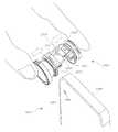
- FIG. 5illustrates an embodiment of a removable mount configured to make use of a mobile device's input and/or output port for securement.
- FIG. 6illustrates another embodiment of a removable mount configured to make use of a mobile device's input and/or output port for securement.
- FIG. 7illustrates an embodiment of a removable mount that permits attachment and selective use of multiple optical components.
- FIGS. 8A-8Billustrate another embodiment of a removable mount that permits attachment and selective use of multiple optical components.
- FIGS. 9A-9Billustrate another embodiment of a removable mount that permits attachment and selective use of multiple optical components.
- FIGS. 10A-10Billustrate another embodiment of a removable mount that permits attachment and selective use of multiple optical components.
- FIGS. 11A-11Billustrate another embodiment of a removable mount that permits attachment and selective use of multiple optical components.
- FIGS. 12A-12Billustrate an embodiment of a removable optical device configured to attach to mobile devices through the use of clamping mechanisms.
- FIGS. 13A-13Billustrate another embodiment of a removable optical device configured to attach to mobile devices through the use of clamping mechanisms.
- FIGS. 14A-14Cillustrate an embodiment of a removable optical device configured for use with wearable accessories.
- FIGS. 15A-15Billustrate another embodiment of a removable optical device configured for use with wearable accessories.
- lensin this specification is used in its ordinary sense, and includes powered lenses (e.g., lenses that focus, magnify, enlarge, or. otherwise alter the direction of light passing through the lens), plano lenses (e.g., lenses that are generally planar, lenses that do not taper in thickness, and/or lenses that are not powered), simple lenses, compound lenses, generally spherical lenses, generally toroidal lenses, generally cylindrical lenses, etc.
- powered lensese.g., lenses that focus, magnify, enlarge, or. otherwise alter the direction of light passing through the lens
- plano lensese.g., lenses that are generally planar, lenses that do not taper in thickness, and/or lenses that are not powered
- simple lensescompound lenses
- compound lensesgenerally spherical lenses, generally toroidal lenses, generally cylindrical lenses, etc.
- Any imaging device described or illustrated in this specificationcan include a retainer attached to one or more lenses or optical regions with one or more different features, including but not limited to a constant or variable magnifying lens, a wide-angle lens, a fish-eye lens, a telescopic lens, a macro lens, a constant or variable polarizing lens, an anti-reflection lens, a contrast-enhancing lens, a light-attenuating lens, a colored lens, or any combination of the foregoing, etc.
- a retainer attached to one or more lenses or optical regions with one or more different featuresincluding but not limited to a constant or variable magnifying lens, a wide-angle lens, a fish-eye lens, a telescopic lens, a macro lens, a constant or variable polarizing lens, an anti-reflection lens, a contrast-enhancing lens, a light-attenuating lens, a colored lens, or any combination of the foregoing, etc.
- mobile electronic devicesand “mobile devices” in this specification are used in their ordinary sense, and include mobile telephones, mobile texting devices, media players, electronic tablet devices, laptop computers, desktop computers, gaming devices, wearable electronic devices (e.g., “smart watches” or “smart eyewear”), and/or mobile electronic communication devices capable of linking electronically to another device or to a network such as the Internet, etc.
- Some mobile electronic devicesinclude one or more onboard cameras that can be used for various imaging purposes, such as photography and video recording.
- some mobile electronic devicesinclude one or more illumination components, such as one or more lights, and/or flashes, etc., that can be used for photography, videography, and/or other purposes (e.g., as a flash light).
- Auxiliary optical systemscomprising lens components or other optical components can be removably attached to mobile electronic devices to selectively enhance or otherwise change an image created from light that is transmitted through a lens to an onboard camera lens of the mobile electronic devices.
- lens componentssuch as those disclosed in U.S. Pat. No. 8,279,544, which is incorporated herein by reference in its entirety for all that it discloses, may be secured to a mobile electronic device by a clip that contacts generally opposing sides of the mobile electronic device.
- the lens componentmay include a different lens on each side of the clip portion (e.g., one side may have a fisheye lens, while the generally opposing side may have a wide angle, macro, telephoto, or some other photographic lens).
- the usermay rotate the lens component so that the lens from other side of the clip portion is positioned to alter light passing through to the onboard camera lens of the mobile electronic device.
- the mobile electronic device 1320 illustrated in FIG. 1is similar to an iPhone 5/5S, sold by Apple, Inc. of Cupertino, Calif. Any other mobile electronic device can be used.
- an onboard camera lens 132is positioned near a first corner of the mobile device 1320 where first and second generally orthogonal sides 1304 and 1306 generally converge.
- the first and second sides 1304 , 1306can be located on generally opposing sides of the mobile electronic device 100 from a second corner or from third and fourth generally orthogonal sides, thereby positioning the input or output devices a substantial distance away from the third and fourth generally orthogonal sides or a convergence thereof.
- a mobile device 1320may be configured to accept removable lenses and/or cameras.
- a lens receptacle 1322may be positioned on, within, or beneath an essentially planar surface of the mobile device 1320 .
- An onboard camera lensmay be positioned partially or completely within or adjacent to the lens receptacle 1322 , and the lens receptacle 1322 may be configured to allow installation and use of auxiliary components (e.g., telephoto lenses, wide angle lenses, lens filters, etc.) with the onboard camera lens.
- auxiliary componentse.g., telephoto lenses, wide angle lenses, lens filters, etc.
- An adapter 1332can be used to facilitate the attachment and use of a removably attachable optical device 1330 , such as one or more of the removably attachable optical devices disclosed in U.S. Pat. No. 8,279,544.
- the adapter 1332may comprise one or more connection features configured to connect with one or more corresponding connection features of a mobile electronic device (e.g., within the lens receptacle, on the surface of the device, or on a removable case attached to and made part of the device).
- the adapter 1332may be a multi-pronged adapter configured to be coupled, attached, or inserted into a multi-recessed receptacle 1322 .
- the adapter 1332may be connected in a variety of different manners, such as snapping into the lens receptacle 1322 , screwing or rotating into the lens receptacle 1322 , and/or installing into the lens receptacle 1322 using a bayonet mount, etc.
- the adapter 1332can provide one or more connection advantages, such as protecting the surface of the mobile device 1320 , providing an essentially flat surface for attachment of a removably attachable optical device 1330 , and/or providing a surface with enhanced gripping or tacky qualities to improve securement of the optical device 1330 , etc.
- the receptacle 1322 of the mobile device 1320may be a camera receptacle instead of, or in addition to, a lens receptacle.
- a camera receptaclemay be positioned on, within, or beneath an essentially planar surface of the mobile device 1320 , and may be configured to allow installation and use of removable camera lenses and/or other optical components.
- An adapter 1342may include an integrated camera lens or other optical component 1344 , and the adapter 1342 may also be configured to facilitate the attachment and use of an auxiliary optical device 1330 , as described above.
- an adapter or mounting component 1352can be used with a mobile device, such as the mobile device 1320 described above, to facilitate the use of separate optical components 1360 (e.g., lenses, filters, etc.) with the mobile device 1320 .
- the mobile device 1320 described abovemay include a receptacle 1322 configured to accept removable cameras, lenses, and other optical components.
- a mounting component 1352can be installed into (e.g., attached to, inserted into, snapped into, or otherwise coupled to) the receptacle 1322 to allow the use of separate optical components 1360 (e.g., lenses, filters, etc.).
- the optical components 1360may not be attachable to the receptacle 1322 or mobile device 1320 without the aid of a mounting component 1352 or some other adapter or component (e.g., the optical components 1360 may not have their own attachment clip or clamping structure, as the optical device 1330 shown in FIG. 1 does).
- the mounting component 1352can be attached to the mobile device in any suitable manner, including by using one or more structures described or shown in this specification used to attach any other structure to a mobile electronic device.
- the mounting component 1352may provide an attachment structure 1354 , such as a slot, track, or channel, to facilitate attachment of one of a collection of different optical components 1360 .
- the optical components 1360may include one or more complementary attachment structures 1362 configured to facilitate attachment of the optical components 1360 to the mounting component 1352 .
- an optical component 1360may include one or more tabs or ridges that can be inserted into a corresponding slot, track, or channel of the mounting component 1352 .
- the complementary attachment structures 1362may be keyed to the attachment structure 1354 of the mounting component 1352 in order to ensure proper attachment of the optical component 1360 .
- an optical component 1360may be attached to a mounting component 1352 by using an attachment motion, such as a rotating or sliding motion, to secure the optical component 1360 to the mounting component 1352 .
- an attachment motionsuch as a rotating or sliding motion
- Such an attachment motioncan be used to properly align the complementary attachment structure(s) 1362 with the attachment structure 1354 and complete the attachment process.
- the optical component 1360can alter light that passes through an aperture 1356 of the adapter 1352 to an onboard camera of the mobile device 1320 .
- a series of different optical components 1360can be rapidly and easily removable, interchangeable, and/or replaceable by a user, without requiring the use of tools in some embodiments.
- a collection of different optical componentscan provide many different interchangeable or adjustable photographic options to a user, such as optical components configured to provide and/or to adjust optical features such as lenses for magnification, polarization, color tint, filtering, anti-reflection, contrast enhancement, wide-angle, and/or fish eye, etc.
- optical componentsconfigured to provide and/or to adjust optical features such as lenses for magnification, polarization, color tint, filtering, anti-reflection, contrast enhancement, wide-angle, and/or fish eye, etc.
- a collection of lenses with different optical featurescan be provided or used in connection with any component or system described in this specification.
- a mounting component 1352can permit one or more lenses of a collection to be used on a variety of different mobile devices. This may be particularly advantageous in situations where a user may acquire many different lenses with different optical features for use with a particular mobile device owned by the user, but then the user may later replace the mobile electronic device with another mobile electronic device of a newer or different model, or the user may use multiple mobile electronic devices in different settings, or the user may want to permit a friend to use one or more lenses of the user's lens collection with the friend's mobile electronic device of a newer or different model. To permit compatibility with changes of mobile devices, a plurality of different mounting components 1352 can be made available for removable attachment to the same collection of lenses.
- Each of the various mounting components 1352can correspond with and be attachable to one or more different types, configurations, or models of mobile electronic devices, depending upon the specific dimensions, camera locations, protective case options, and other features that differentiate various mobile devices.
- various mounting components 1352 tailored for different types, configurations, or models of mobile electronic devicesusers can merely replace the mounting component 1352 when a different mobile electronic device is used without requiring replacement of the collection of optical components 1360 .
- the mobile device 1320may include a camera receptacle instead of, or in addition to, a lens receptacle.
- a camera receptaclemay be positioned on an essentially planar surface of the mobile device 1320 , and may be configured to allow installation and use of removable cameras, lenses, and/or other optical components.
- an adapter or mounting component 1372may include an integrated camera, lens, or other optical component 1376 , and the mounting component 1372 may also be configured to facilitate the attachment and use of various auxiliary optical components 1360 .
- the mounting components 1372 with integrated camera lenses or other optical componentsmay be provided in various configurations tailored for different types, configurations, or models of mobile electronic devices as described above with respect to the mounting components 1352 .
- Any and all structures, steps, methods, or components described in this specification for a lenscan also or alternatively be used for a camera (e.g., either an onboard camera embedded in a mobile electronic device or a camera positioned on or in any of the clips or other attachment structures described and illustrated in this specification to facilitate connection with a mobile electronic device).
- FIG. 3illustrates a removably attachable mounting component 1410 that may be attached to a mobile device 1400 to facilitate the use of various auxiliary optical components 1416 that may include any of the features described herein.
- the mobile device 1400may include an onboard camera lens 1406 located on a generally planar surface and generally near the intersection of two generally perpendicular edges 1402 , 1404 of the mobile electronic device 1400 .
- the onboard camera lens 1406may be substantially flush with, or positioned beneath, the generally planar surface.
- the mobile device 1400may be an iPhone 5/5S, manufactured by Apple.
- a mounting component 1410may be attached to the mobile device 1400 such that an aperture 1414 of the mounting component is generally aligned with the onboard camera lens 1406 .
- the optical component 1416When an optical component 1416 is attached to the mounting component, the optical component 1416 may be automatically positioned such that the optical axis of the optical component 1416 is aligned with the aperture 1414 and onboard camera lens 1406 , without requiring additional manual alignment or adjustment by a user.
- the mounting component 1410may include two generally parallel sides configured to form a channel between the two generally parallel sides.
- a portion of the mobile device 1400e.g., a corner
- the two generally parallel sides of the mounting component 1410may contact two generally parallel, generally planar surfaces of the mobile device 1400 (e.g., the “front” and “back” faces of the mobile device).
- One or both of the generally parallel sides of the mounting component 1410may exert a gripping force on the mobile device 1400 , or may include an area of increased friction, such as a tacky layer, to aid in securement of the mounting component 1410 to the mobile device 1400 .
- the mounting component 1410may be configured to attach to the mobile device 1400 using any of the mechanisms or techniques described above, described in U.S. Pat. No. 8,279,544, or known to those of skill in the art.
- the mounting component 1410may include an attachment structure 1412 , such as a slot, track, or channel, to facilitate attachment of an optical component 1416 .
- An optical component 1416may have one or more complementary attachment structures 1418 such as tabs or ridges that can, e.g., be inserted into the attachment structure 1412 of the mounting component 1410 .
- the complementary attachment structures 1418may be keyed to the, attachment structure 1412 of the mounting component 1410 in order to ensure proper attachment of the optical component 1416 .
- an optical component 1416can alter light that passes through an aperture 1414 of the mounting component 1410 to an onboard camera of the mobile device 1400 .
- an optical component 1416may be attached to a mounting component 1410 by using an attachment motion, such as a rotating or sliding motion, to secure the optical component to the mounting component 1410 .
- an attachment motioncan be used to properly align the complementary attachment structure(s) 1418 with the attachment structure 1412 and complete the attachment process.
- the mounting component 1410may include multiple attachment structures 1412 , such as one on each generally parallel side of the mounting component 1410 , to allow attachment of multiple optical components 1416 (e.g., an optical component 1416 generally adjacent to each of a front and back face of the mobile device 1400 ).
- the attachment motioncan involve advancing the lens toward the mounting component and/or connecting the lens and the mounting component in a generally vertically downward path. In some embodiments, as illustrated, the attachment motion can involve advancing the lens toward the mounting component and/or connecting the lens and the mounting component in a generally diagonally downward path.
- Many different attachment motions and structurescan be utilized. As illustrated, at least two different lenses can be attached to the same mounting component at the same time. Each lens can have different optical features.
- a mounting component 1410may include a mounting structure 1412 in a generally orthogonal orientation with respect to an edge 1404 of the mobile device 1400 near the onboard camera lens 1406 . Attachment of an optical component 1416 can therefore be performed from an area generally near the edge 1404 using a motion generally orthogonal to the edge 1404 .
- a mounting component 1420may include a mounting structure 1422 in a generally diagonal orientation with respect to one or more edges 1402 or 1404 of the mobile device 1400 (or the convergence thereof) near the onboard camera lens 1406 . Attachment of an optical component 1416 can therefore be performed using a motion generally diagonal with respect one or more edges 1402 , 1404 of the mobile device 1400 .
- FIG. 4illustrates embodiments of optical component mounts for use with various mobile devices.
- the mounting componentsare not required to be positioned on or near a corner of the mobile device 1500 , but instead may be positioned at various locations on an edge or other surface of the mobile device 1500 .
- Such mounting componentsmay therefore be used with mobile devices that include onboard cameras that are not located near a corner.
- a mounting component 1510may be configured for use with a mobile device 1500 that includes an onboard camera lens 1506 that is centrally located, such as at or near a generally vertical line that generally bisects the mobile device from top to bottom.
- the onboard camera lens 1506may not be substantially closer to one corner of the device 1500 than a second corner of the device 1500 sharing a common edge 1502 , as with the Samsung Galaxy S5, manufactured by Samsung.
- the mounting component 1510may be configured to removably attach to a mobile device 1500 and facilitate the use of separate optical components 1520 with an onboard camera 1506 of the mobile device 1500 .
- the mounting component 1510may include a first side 1514 coupled to a securement portion 1512 .
- the first side 1514may include a stabilizing portion 1516 that aids in stabilizing the mounting component 1510 in a particular position with respect to the mobile device 1500 .
- the first side 1514may include a groove or channel that is shaped and/or sized to correspond to a surface feature, such as a protruding region 1504 , on the mobile device 1500 .
- a generally planar face of the mobile device 1500may include a region 1504 that is curved or recessed or that protrudes from the generally planar face.
- the region 1504may include or surround an onboard camera lens 1506 .
- the stabilizing portion 1516 (e.g., the groove or channel) of the first side 1514 of the mounting component 1510can be complementary in shape to the protruding region 1504 , thereby allowing the first side 1514 to be positioned substantially flush with the generally planar face of the mobile device 1500 .
- the stabilizing portion 1516 of the first side 1514can inhibit or prevent sliding or lateral movement of the mounting component 1510 with respect to the generally planar face of the mobile device 1500 .
- the securement portion 1512 of the mounting component 1510can contact an edge 1502 of the mobile device 1500 , aiding in placement and/or securement of the mounting component 1510 to the mobile device 1500 .
- the securement portion 1512 of the mounting component 1510may partially or completely wrap around an edge of the mobile device 1500 to contact a second generally planar surface or face of the mobile device 1500 .
- the securement portionmay be configured to contact a plurality of different surfaces of the mobile device at the same time.
- the securement portion 1512 and first side 1514 of the mounting component 1510may form a channel.
- the first side 1514 and a part of the securement portion 1512 that partially or completely wraps around an edge of the mobile device 1500may form first and second generally parallel walls of the channel, respectively.
- the mounting component 1510may be attached to the mobile device 1500 such that a portion of the mobile device 1500 is inserted into the channel (e.g., a portion of an edge 1502 of the mobile device 1500 ).
- the width of the channele.g., the distance between the first and second walls of the channel
- the width of the channelmay be generally complementary to the thickness of the mobile device 1500 (e.g., the distance between the first and second generally planar, generally parallel sides, or the front and back “faces”).
- the width of the channelmay be slightly less than the thickness of the mobile device 1500 .
- one or both of walls of the channelmay be temporarily deflected or forced outward during attachment in order to install the mounting component 1510 on the mobile device 1500 .
- One or both of the walls of the channelmay be biased inward (e.g., toward the other wall) so as to exert a gripping force on the mobile device 1500 .
- some portion of the first and/or second wallsmay be rubbery, tacky or otherwise configured with a coefficient of friction sufficient to secure the mounting component 1510 to the mobile device 1500 .
- An optical component 1520may be permanently or semi-permanently coupled to the mounting component 1510 .
- lensessuch as lens filters or magnifiers
- auxiliary camerasand the like may be mounted to the mounting component 1510 .
- the optical componentscan alter light as it passes through the optical component to the mobile device 1500 .
- a plurality of different optical components 1520can be removably mounted to the mounting component 1510 for use with the mobile device 1500 .
- the mounting component 1510may include an optical component receptacle 1518 (e.g., on the first side 1514 ).
- the optical component receptacle 1518may define an aperture through which light may pass through the mounting component 1510 to an onboard camera 1506 of the mobile device 1500 .
- the optical component receptacle 1518may be threaded, configured as a bayonet mount, etc.
- Optical components 1520may be mounted to the mounting clip 1510 by attaching them to the optical component receptacle 1518 .
- the interface or attachment mechanism between the optical component and optical component receptaclecan have many different forms, including any of those described and/or illustrated in this specification for attaching any components.
- the first side of the mounting componentmay include a stabilizing portion configured with shapes or features other than those described above.
- a mounting component 1530may include a first side 1534 with a groove 1536 configured to fit the shape of the onboard camera or nearby region of the mobile device 1500 .
- a mounting clip 1540may include a first side 1542 shaped so as to substantially match or complement the curvature of a face of a mobile device, such as a face that includes an onboard camera.
- the example shapes and features shown and describedare illustrative only, and are not intended to be limiting.
- FIG. 5shows additional embodiments of mounting components, some of which include an anchoring component for aiding in placement or securement of the mounting components to mobile devices.
- mounting component 1560includes an post, rod, dowel, or other anchor 1564 that is configured to be inserted into a pre-existing port 1508 of the mobile device 1500 that is intended for some other functional purpose, such as an electronic port (e.g., a headphone jack, microphone jack, USB port, network cable jack, power cable jack, memory card slot, or any other hole, slot, or input and/or output port of the device).
- the anchor 1564may be inserted into, attached to, or protrude from, a securement portion 1562 or some other portion of the mounting component 1560 .
- the anchor 1564When the mounting component 1560 is attached to the mobile device 1500 , the anchor 1564 may be inserted into the headphone jack 1508 of the mobile device, thereby securing the mounting component 1560 to the mobile device 1500 (e.g., inhibiting or preventing accidental removal). Use of the anchor 1564 in this manner may also aid in positioning the mounting component 1560 with respect to the mobile device 1500 such that optical components 1520 may be used with an onboard camera lens 1506 of the mobile device 1500 . In addition, use of the anchor 1564 in this manor may aid in stabilizing the mounting component 1560 in a certain position with respect to the mobile device 1500 (e.g., resist sliding or lateral movement of the mounting component 1560 with respect to the mobile device 1500 ).
- a stabilizing portionsuch as those described above, may also be included, e.g., on a first side of the mounting component 1560 , to further aid in securing, positioning, and/or stabilizing the mounting component 1560 .
- the use of an anchoring componentmay permit the mounting component 1560 to contact less than three different sides of the mobile device (e.g., only two sides).
- the mounting componentmay contact only the face of the mobile electronic device 1500 in which the onboard camera 1506 is embedded plus one other side of the mobile electronic device, such as a top edge 1502 of the mobile electronic device, while entirely or nearly entirely avoiding contact with the opposing face of the mobile electronic device that includes the screen or other components, in a manner that would otherwise block a portion of a screen or interfere with normal usage of the mobile device.
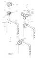
- FIG. 6shows additional embodiments of mounting components.
- a mounting component 1570may include an anchor 1574 that can facilitate electronic communication with the mobile device 1500 .
- the anchor 1574may be used to establish an electrical connection with the mobile device 1500 via a headphone jack or some other input and/or output port of the mobile device 1500 .
- the mounting component 1570may include a port 1576 , such as an input and/or output port that is configured to enable a pass-through electrical or optical connection to the anchoring port on the mobile device.
- electrical circuitry or wiring in the mounting component 1570may facilitate communication between the anchor 1574 and the port 1576 , and therefore between the mobile device 1500 and some other component or accessory.
- a separate accessorye.g., ear phones, a flash, a speaker, etc.
- auxiliary cable 1578may be coupled to the mounting component 1570 via an auxiliary cable 1578 .
- the use of the mobile device port as an anchoring locationdoes not prevent or interfere with the use or the originally intended functionality of the port on the mobile electronic device.
- a mounting component 1570may include one or more electronically actuated or enabled features that include an electronic connection with the mobile electronic device through an electronic port on the mobile electronic device, which may or may not also be a mechanical anchoring location for the mounting location.
- an electronic connection between the mounting componentmay actuate and/or provide power to an indicator (e.g., an LED light, a moving flag arm), a focusing or zooming mechanism, a polarizing adjuster, a remote controller, a tethered or remove photographic trigger, and/or an illuminating component 1580 (e.g., an external flash powered by a flash bulb or LED).
- an indicatore.g., an LED light, a moving flag arm
- a focusing or zooming mechanisme.g., a focusing or zooming mechanism
- a polarizing adjustere.g., a polarizing adjuster
- a remote controllere.g., a tethered or remove photographic trigger
- an illuminating component 1580
- the external flash 1580can be triggered via a connection point or an anchor 1574 of the mounting component 1570 inserted into a port of the mobile device 1500 .
- the mobile devicemay be configured to activate the flash 1580 by sending an electrical communication through an output port.
- the external flash 1580may draw electrical power from a mobile phone port to which the mounting component is anchored, or the mounting component 1572 may include a battery.
- the external flash 1580may be triggered through other means, such as wireless communication (e.g., Bluetooth® transmission).
- the anchor 1574may or may not provide electrical communication with the mobile device 1500 .
- the mounting componentmay not include a separate external flash or may not include an external flash at all, but rather may be configured to convey light from a flash of the mobile device 1500 to an area generally in the field of view of an optical component 1520 attached to the mounting component 1572 .
- the mounting component 1572may include a light-conveying structure, such as an optical fiber, a light pipe, a transparent or translucent window, etc.
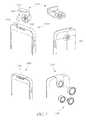
- FIGS. 7, 8A, 8B, 9A, 9B, 10A, 10B, 11A and 11Bshow embodiments of mounting components to which multiple optical components may be mounted on a same side of a device at the same time.
- two or more optical componentsmay be coupled to a single mounting component permanently, or for a user-selectable period of time.
- the presence of two or more optical componentscan provide a user with a choice of optical components for any particular photo or video, while also reducing or eliminating the need to manually remove and replace a currently attached optical component with a desired optical component.
- Optical componentsmay be permanently coupled or attached to the mounting component, or the mounting component may allow for the removal and re-attachment of various removable optical components, as described above.
- FIG. 7shows an embodiment of a mounting component 1610 with a sliding multi-component member 1622 to which multiple optical components 1630 may be mounted.
- the sliding multi-component member 1622may include two or more optical component receptacles 1624 (or permanently/semi-permanently attached optical components).
- the mounting component 1610may include a first side 1620 and a securement portion 1612 .
- the first side 1620may include a slide-guiding member for the sliding multi-component member 1622 , such as a housing, a track, a groove, and/or a channel in which the sliding multi-component member 1622 may be seated.
- the sliding multi-component member 1622can slide or otherwise move within the mounting component 1610 housing between two or more positions.
- a first positionmay place a first optical component 1630 adjacent an onboard camera lens 1606 of the mobile device 1600 for use with the onboard camera lens 1606 .
- a second optical componentmay be positioned adjacent the onboard camera lens 1606 .
- a gasket 1618may be coupled, co-molded, or otherwise attached to a surface of the mounting component 1610 facing the mobile device 1600 to provide a light-tight seal with the onboard camera lens 1606 .
- the width, length, and/or one or more other dimensions of the sliding member 1622 and/or the slide-guiding membercan be configured to permit a first one of a plurality of conjoined or attached optical components 1630 to be generally positioned over or generally aligned with an onboard camera of a mobile electronic device while at the same time a second of the conjoined or attached optical components 1630 is positioned at or in abutment with an end of a channel or groove or otherwise positioned at an engagement or other stopping location, permitting the position of the second optical component 1630 in such location to effectively position properly the first optical component 1630 with respect to the camera.
- a continuous channel or groove with endpoints configured to be positioned on both sides of the onboard cameracan permit selective positioning of a plurality of different optical components 1630 generally in front of or generally in alignment with the onboard camera 1606 by sliding the sliding member 1622 back and forth between stopping locations on generally opposite sides from the onboard camera 1606 .
- the mounting component 1610may include an anchor 1614 and/or an electrical connection which may be inserted into a port 1604 of the mobile device 1600 .
- the anchor 1614can secure, position, and/or stabilize the mounting component 1610 with respect to the mobile device 1600 .
- the anchor 1614may facilitate electrical communication with the mobile device 1600 .
- the anchor 1614 and/or electrical connectioncan include any or all features described elsewhere in this specification for other anchors and/or electrical connections.
- FIGS. 8A and 8Bshow an embodiment of a mounting component 1910 with a rotating multi-component member 1916 .
- the rotating multi-component member 1916may rotate through two or more positions with respect to a securement portion 1912 to which the rotating multi-component member 1916 is coupled, thereby positioning a different optical component 1630 in optical alignment with an onboard camera lens 1606 of the mobile device 1606 in each of the two or more positions.
- one of the optical components 1630is a lens configured to expand the field of view (e.g., a fisheye lens)
- a second optical componentmay be sized proportionately smaller so as to reduce or eliminate the possibility that the second optical component is captured in an image taken with the fisheye lens.
- the second optical componentmay be positioned on the rotating multi-component member 1916 such that it will not be captured in an image taken using the fisheye lens (e.g., out of the fisheye lens's actual field of view, or within the fisheye lens's field of view but outside the area captured in an image, such as the top or bottom of an image in landscape orientation, or the left or right of an image in portrait orientation).
- a particular optical component 1630 amay be positioned in optical alignment with the onboard camera of the mobile device 1600 in a first position.
- a different optical component 1630 bmay be positioned in optical alignment with the onboard camera.
- the rotating multi-component member 1916may rotate about a rotating point 1914 , such as a pin or a bolt that also couples to the rotating multi-component member 1916 to the securement portion 1912 .
- the rotating point 1914can be positioned substantially below an upper edge of the securement portion 1912 , such as in a region that is located at generally about the vertical midpoint of the securement portion 1912 .
- the mounting component 1910may utilize an anchor 1920 to secure, position, and/or stabilize the mounting component 1910 with respect to the mobile device, as described above.
- an anchor 1920to secure, position, and/or stabilize the mounting component 1910 with respect to the mobile device, as described above.
- the embodiment of FIGS. 8A and 8Bcan be used with any other features, structures, materials, or steps described elsewhere in this specification, as with all embodiments in this specification.
- one or more optical components 1630may be removably attached to the mounting component 1910 (e.g., to optical component receptacles thereof) using various attachment structures.
- the anchor 1920may provide an electrical connection to the mobile device via a port 1608 into which the anchor 1920 is inserted.
- FIGS. 9A and 9Bshow an embodiment of a mounting component 2010 with multiple pivoting and/or rotating members 2016 .
- independently pivoting and/or rotating members 2016may include component receptacles for removably mounting optical components 1630 , or they may include permanently or semi-permanently attached optical components 1630 .
- Each independently pivoting member 2016may pivot about a pivot point 2014 , such as a pin or bolt that couples one or more of the independently pivoting members 2016 to the mounting component 2010 .
- a usermay pivot a first independently pivoting member 2016 about the pivot point 2014 without affecting the position of a second independently pivoting member 2016 b .
- a usermay therefore adjust the positioning of the independently pivoting members 2016 to cover or uncover components or features of the mobile device 1600 (e.g., flash photography components, communication ports, etc.), achieve a comfortable or desirable configuration of components for holding the device 1600 with the mounting component 2010 attached, etc.
- components or features of the mobile device 1600e.g., flash photography components, communication ports, etc.
- FIGS. 9A and 9Bcan be used with any other features, structures, materials, or steps described elsewhere in this specification, as with all embodiments in this specification.
- one or more optical, components 1630may be removably attached to the mounting component 2010 (e.g., to optical component receptacles thereof) using various attachment structures.
- an anchor 2020may be used to secure the mounting component 2010 to the mobile device 1600 , provide an electrical connection to the mobile device via a port 1608 into which the anchor 2020 is inserted, etc.
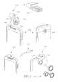
- FIGS. 10A and 10Bshow an embodiment of a mounting component 2110 with a pivoting multi-component member 2116 .
- the pivoting multi-component member 2116may be coupled to the mounting component 2110 such that the pivoting multi-component member 2116 can pivot between two or more positions with respect to the mounting component 2116 and mobile device 1600 .
- the pivoting multi-component member 2116may pivot at a pivot point 2114 , such as a pin or a bolt that also couples the pivoting multi-component member 2116 to the mounting component 2110 .
- a first optical component 1630 amay be positioned for use with an onboard camera lens 1606 of the mobile device 1600 .
- a usermay then pivot the multi-component member 2116 about the pivot point 2114 to a second position.
- a different optical component 1630 bmay be positioned for use with the onboard camera lens 1606 .
- FIGS. 10A and 10Bcan be used with any other features, structures, materials, or steps described elsewhere in this specification, as with all embodiments in this specification.
- one or more optical components 1630may be removably attached to the mounting component 2110 (e.g., to optical component receptacles thereof) using various attachment structures.
- an anchor 2118may be used to secure the mounting component 2110 to the mobile device 1600 , provide an electrical connection to the mobile device via a port 1608 into which the anchor 2118 is inserted, etc.
- the mounting component 2110may include a clip portion to secure the mounting component to a mobile device.
- the clip portionmay utilize any of the features or methods described herein, described in U.S. Pat. No. 8,279,544, or known to those of skill in the art to secure, position, and stabilize the mounting component with respect to the mobile device.
- a pivoting, rotating, sliding, or otherwise movable multi-component membermay be coupled to the clip portion, and may move relative to the clip portion as described above with respect to various mounting components, such as those illustrated in FIGS. 9-10 .
- FIGS. 11A and 11Bshow an embodiment of a mounting component 2300 with a pivoting multi-component member 2320 . Similar to other pivoting members described herein, the pivoting multi-component member 2320 shown in FIGS. 11A and 11B may pivot about a pivot point, such as a pin or a bolt, which couples the multi-component member 2320 to a securement portion 2310 of the mounting component 2300 .
- a pivot pointsuch as a pin or a bolt
- the securement portion 2310may be configured with one or more alignment structures 2312 , such as detents, spring-loaded ball bearings, or the like, to stop and/or resist the pivoting motion of the multi-component member 2320 at specific positions (e.g., a first position for using a first optical component with an onboard camera lens of the mobile device, and a second position for using a second optical component).
- the securement portion 2310may include one or more protruding alignment structures 2312 , such as bumps, protrusions, or ball detents.
- the multi-component member 2320may include one or more complementary alignment structures 2322 which correspond to the alignment structures 2312 of the securement portion 2310 .
- the multi-component member 2320may include recessed alignment structures 2322 , such as holes, indentations, or grooves, that receive a protruding alignment structure 2312 and temporarily stop or resist further pivoting of the multi-component member 2320 .
- the alignment structures 2312 , 2322may be located on the securement portion 2310 and multi-component member 2320 , respectively, such that they temporarily stop or resist further pivoting of the multi-component member 2320 at any one of multiple positions. Each of the positions may correspond to a location at which a particular optical component is positioned for use with an onboard camera lens of the mobile device.
- the securement portion 2310may include recessed alignment structures and the multi-component member 2320 may include protruding alignment structures.
- the multi-component member 2320 and securement portion 2310may each include a combination of protruding and recessed alignment structures.
- FIGS. 12A and 12Billustrate embodiments of an auxiliary optical device that may be secured to a mobile device by clamping or otherwise contracting or squeezing upon a portion of the mobile device.
- an auxiliary optical device 2520may be clamped to a mobile device 1400 by squeezing two or more portions 2512 , 2514 of the auxiliary optical device 2520 together.
- the distance between a face of the first portion 2512 and a face of the second portion 2514can be increased or decreased to attach or remove the optical device 2520 to or from the mobile electronic device 1400 .
- a portion of the mobile device 1400may be positioned between the first portion 2512 and second portion 2514 of the auxiliary optical device 2520 .
- a usermay exert pressure or otherwise urge the first portion 2512 towards the second portion 2514 .
- a latchmay secure the first and second portions such that the auxiliary lens component is clamped to the mobile device.
- the auxiliary optical device 2520may automatically register against first and second generally orthogonal, generally converging edges 1402 , 1404 of the mobile device 1400 , as described in U.S. Pat. No. 8,279,544.
- a second optical componentmay be coupled to the other of the first or second portions 2512 or 2514 , and a user may remove, rotate, and re-attach the auxiliary optical device 2520 to the mobile device 1400 such that the second optical component is automatically oriented in optical alignment with the onboard camera lens 1406 .
- the auxiliary optical device 2520may include a plurality of expanding and contracting members 2516 .
- the members 2516may secure the first portion 2512 of the auxiliary optical device 2520 to the second portion 2514 . Although three (3) such members 2516 are shown in FIG. 12A , some implementations may use additional or fewer members 2516 .
- the members 2516may be telescoping members such that they can expand and contract in sections. When a portion of a mobile device 1400 (e.g., a corner) is positioned between the first and second portions 2512 , 2514 , the first and second portions 2512 , 2514 may be squeezed together, and the members 2516 may retract or contract accordingly.
- a lock and release button 2528 with a latch 2524can be coupled to either the first or the second portion 2512 or 2514 , and the latch 2524 can engage a catch 2522 on the opposite portion (e.g., not the portion to which the lock and release button 2528 is coupled).
- the latch 2524may release the catch 2522 , and the first and second portions 2512 and 2514 may be manually or automatically expanded away from each other.
- FIGS. 13A and 13Billustrate an auxiliary optical device 2530 that may be spring-loaded or otherwise biased to a clamping position.
- the auxiliary optical device 2530can include a first portion 2532 coupled to a second portion 2534 by members 2536 , similar to the auxiliary optical device 2520 described above.
- the expanding and contracting members 2536may be spring loaded or biased such that they urge the first and second portions 2532 , 2534 toward each other. As a result, a user may manually expand the first portion 2532 away from the second portion 2534 to attach the auxiliary optical device 2530 to a mobile device 1400 .
- the usermay then release one or both of the portions 2532 , 2534 , and the bias of the members 2536 can clamp the auxiliary optical device 2530 to the mobile device 1400 without a latch or other mechanism.
- a usermay perform a similar operation to unclamp the auxiliary optical device 2530 from the mobile device. For example, the user may expand a first portion 2532 away from a second portion 2534 to remove the clamped auxiliary optical device 2530 from the mobile device 1400 .
- an optical component coupled to the first or second portion 2532 or 2534may be automatically oriented in optical alignment with an onboard camera lens 1406 of the mobile device such that no manual alignment or adjustment is necessary.
- the auxiliary optical device 2530may automatically register against first and second generally orthogonal, generally converging edges 1402 , 1404 of the mobile device 1400 , as described in U.S. Pat. No. 8,279,544.
- a second optical componentmay be coupled to the other of the first or second portions 2532 or 2534 , and a user may remove, rotate, and re-attach the auxiliary optical device 2530 to the mobile device 1400 such that the second optical component is automatically oriented in optical alignment with the onboard camera lens 1406 .
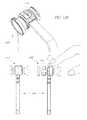
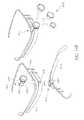
- FIGS. 14A-14C and 15A-15Billustrate embodiments of auxiliary optical devices for use with other accessories, such as headwear or eyewear (such as a heads-up display) with onboard camera lenses.
- the example of an eyewear accessory 2610 shown in FIGS. 14A-14Cis a Google Glass from Google, although the auxiliary lens components described herein may be used with other headwear, eyewear, or wearable accessories.
- a user 2600may use the onboard camera lens of the eyewear 2610 to capture images and video from the user's point of view.
- the eyewear 2610may include a housing 2614 coupled to a frame 2612 . As shown in FIG. 14B , the housing 2614 may include an onboard camera lens 2640 . An auxiliary optical device 2616 may be removably attached to the eyewear 2610 in order to enhance or alter light that passes to the onboard camera lens 2640 , as described above.
- the auxiliary optical device 2616may include a permanently or semi-permanently attached optical component 2668 , such as a lens or a filter. In some embodiments, the auxiliary optical device 2616 may provide a lens receptacle to which various removable optical components 2670 may be attached, as described above.
- the auxiliary optical device 2616may include a clip portion 2664 to which an optical component 2668 or 2670 may be attached.
- the clip portion 2664may include a first sidewall 2662 and a second sidewall 2666 .
- the first and second sidewalls 2662 , 2666may form a channel into which a portion of the housing 2614 may be inserted.
- the sidewalls 2662 , 2666may be generally parallel, or they may be shaped and/or sized to be generally complementary to the shape and/or size of the housing 2614 to which the clip portion 2664 will be attached.
- the auxiliary optical device 2616may be attached to the eyewear 2610 such that the lens component 2668 is adjacent or generally co-axial with the onboard camera lens 2640 .
- the configuration of the channelmay aid in proper positioning of the auxiliary optical device 2616 to achieve alignment of the optical component 2668 and the onboard camera lens 2640 .
- the contour of the housing 2614may vary, such that the area of the housing 2614 near the onboard camera lens 2640 is unique or different than other areas of the housing 2614 farther from the onboard camera lens 2640 .
- the interior contour of the channel formed by the first and second sidewalls 2662 , 2666may be complementary to the contour of the housing 2614 near the onboard camera lens 2640 . Any of the steps, features, or structures disclosed in this specification relating to any other embodiment can be used instead of or in addition to those described and/or shown in the embodiment of FIGS. 14A-14C .
- the channelmay be resilient, rubbery, tacky, or otherwise provide increased friction to aid in securing the clip portion 2664 to the housing 2614 .
- the exterior shape or surface of the second sidewall 2662e.g., the side that faces the user 2600
- an auxiliary optical device 2680may be configured to clamp onto the housing 2614 or some other portion of the eyewear 2610 .
- the auxiliary optical device 2680may include a first portion 2682 and a second portion 2684 that are movable relative to each other. The first and second portions 2682 , 2684 may clamp onto the eyewear 2610 as described above with respect to FIGS. 12A-12B and 13A-13B .
- FIGS. 15A and 15Bshow an embodiment of an auxiliary optical device 2694 that can be used with a different wearable accessory 2690 .
- the eyewear accessory 2690 shown in FIGS. 15A and 15Bincludes a centrally-located onboard camera lens 2692 .
- the auxiliary optical device 2694includes a clip portion 2698 and an optical component 2696 .
- the clip portion 2698may form a channel into which a portion of the eyewear 2690 may be inserted.
- the channelmay be configured to aid or ensure alignment of the optical component 2696 with the onboard camera lens 2692 when the auxiliary optical device 2694 is attached to the eyewear 2690 .
- a plurality of auxiliary lensescan be retained by a retainer such that, when the retainer is removably attached to a mobile electronic device, at least one of the lenses is configured to be in optical alignment or optical communication with a first onboard camera located on a first side of the mobile electronic device, and at least one of the lenses is configured to be in optical alignment or optical communication with a second onboard camera located on a second side of the mobile electronic device that is generally opposite from the first side of the mobile electronic device, at the same time.
- the retainercan be configured to be switchable by removing and rotating and reattaching the retainer to the mobile electronic device, such that the auxiliary lens that is initially located in optical alignment or communication with the first onboard camera can be positioned in optical alignment or communication with the second onboard camera, and the auxiliary lens that is initially located in optical alignment or communication with the second onboard camera can be positioned in optical alignment or communication with the first onboard camera.
- the simultaneous optical communication with the plurality of auxiliary lenses and each of the plurality of onboard cameras or onboard camera lensescan provide optical enhancements for photographing in multiple directions, including optical enhancement for “selfie” photographs and for other photographs facing away from the user.
- any of the auxiliary lensescan be interchangeable with a selection of different auxiliary lenses having different optical qualities, such as any of those described elsewhere in this specification.
Landscapes
- Physics & Mathematics (AREA)
- General Physics & Mathematics (AREA)
- Optics & Photonics (AREA)
- Structure And Mechanism Of Cameras (AREA)
- Studio Devices (AREA)
Abstract
Description
Claims (19)
Priority Applications (1)
| Application Number | Priority Date | Filing Date | Title |
|---|---|---|---|
| US15/947,581US10447905B2 (en) | 2013-08-07 | 2018-04-06 | Auxiliary optical device having moveable portions |
Applications Claiming Priority (5)
| Application Number | Priority Date | Filing Date | Title |
|---|---|---|---|
| US201361863361P | 2013-08-07 | 2013-08-07 | |
| US14/454,648US9661200B2 (en) | 2013-08-07 | 2014-08-07 | Auxiliary optical components for mobile devices |
| US15/294,426US20170031236A1 (en) | 2013-08-07 | 2016-10-14 | Auxiliary optical components for eyewear |
| US15/649,252US20170310862A1 (en) | 2013-08-07 | 2017-07-13 | Auxiliary optical components for eyewear |
| US15/947,581US10447905B2 (en) | 2013-08-07 | 2018-04-06 | Auxiliary optical device having moveable portions |
Related Parent Applications (1)
| Application Number | Title | Priority Date | Filing Date |
|---|---|---|---|
| US15/649,252ContinuationUS20170310862A1 (en) | 2013-08-07 | 2017-07-13 | Auxiliary optical components for eyewear |
Publications (2)
| Publication Number | Publication Date |
|---|---|
| US20180227471A1 US20180227471A1 (en) | 2018-08-09 |
| US10447905B2true US10447905B2 (en) | 2019-10-15 |
Family
ID=52448354
Family Applications (4)
| Application Number | Title | Priority Date | Filing Date |
|---|---|---|---|
| US14/454,648Expired - Fee RelatedUS9661200B2 (en) | 2013-08-07 | 2014-08-07 | Auxiliary optical components for mobile devices |
| US15/294,426AbandonedUS20170031236A1 (en) | 2013-08-07 | 2016-10-14 | Auxiliary optical components for eyewear |
| US15/649,252AbandonedUS20170310862A1 (en) | 2013-08-07 | 2017-07-13 | Auxiliary optical components for eyewear |
| US15/947,581Expired - Fee RelatedUS10447905B2 (en) | 2013-08-07 | 2018-04-06 | Auxiliary optical device having moveable portions |
Family Applications Before (3)
| Application Number | Title | Priority Date | Filing Date |
|---|---|---|---|
| US14/454,648Expired - Fee RelatedUS9661200B2 (en) | 2013-08-07 | 2014-08-07 | Auxiliary optical components for mobile devices |
| US15/294,426AbandonedUS20170031236A1 (en) | 2013-08-07 | 2016-10-14 | Auxiliary optical components for eyewear |
| US15/649,252AbandonedUS20170310862A1 (en) | 2013-08-07 | 2017-07-13 | Auxiliary optical components for eyewear |
Country Status (1)
| Country | Link |
|---|---|
| US (4) | US9661200B2 (en) |
Cited By (4)
| Publication number | Priority date | Publication date | Assignee | Title |
|---|---|---|---|---|
| US20220038607A1 (en)* | 2020-07-31 | 2022-02-03 | GoPro,Inc | Housing, removable lens, and housing system for an image capture device |
| USD1013762S1 (en) | 2020-07-31 | 2024-02-06 | Gopro, Inc. | Camera housing |
| USD1014603S1 (en) | 2019-09-13 | 2024-02-13 | Gopro, Inc. | Camera housing |
| US12250361B2 (en) | 2022-08-18 | 2025-03-11 | Apple Inc. | Optical assemblies for shared experience |
Families Citing this family (55)
| Publication number | Priority date | Publication date | Assignee | Title |
|---|---|---|---|---|
| CA3194784A1 (en) | 2008-05-20 | 2009-11-26 | University Health Network | Device and method for fluorescence-based imaging and monitoring |
| CN103181154A (en) | 2010-10-29 | 2013-06-26 | 加利福尼亚大学董事会 | Mobile phone microscope apparatus and method for imaging |
| US10345680B2 (en) | 2013-05-21 | 2019-07-09 | Forward Science Technologies, LLC | Optical filtering attachment |
| US9661200B2 (en) | 2013-08-07 | 2017-05-23 | Olloclip, Llc | Auxiliary optical components for mobile devices |
| WO2015035229A2 (en) | 2013-09-05 | 2015-03-12 | Cellscope, Inc. | Apparatuses and methods for mobile imaging and analysis |
| US20150168808A1 (en)* | 2013-12-16 | 2015-06-18 | Earl J. PeQueen | Detachable viewfinder |
| USD754228S1 (en)* | 2014-02-19 | 2016-04-19 | olioclip, LLC | Optical component |
| US9917935B2 (en)* | 2014-03-04 | 2018-03-13 | Houdinix Llc | Multi-layer handheld electronic device |
| DE102014004698B3 (en)* | 2014-03-31 | 2015-08-06 | Matthias Ebel | Lighting for an at least partially human-powered vehicle or its trailer by means of light guide elements, controlled by a mobile terminal or smartphone or by a central light source |
| USD761896S1 (en)* | 2014-04-11 | 2016-07-19 | Olloclip, Llc | Optical component |
| US9454066B2 (en) | 2014-06-19 | 2016-09-27 | Olloclip, Llc | Auxiliary optical components for mobile devices |
| JP6769949B2 (en) | 2014-07-24 | 2020-10-14 | ユニバーシティー ヘルス ネットワーク | Data collection and analysis for diagnostic purposes |
| US20160139495A1 (en)* | 2014-09-18 | 2016-05-19 | Olloclip, Llc | Adapters for attaching accessories to mobile electronic devices |
| USD763340S1 (en)* | 2014-10-02 | 2016-08-09 | Olloclip, Llc | Optical component |
| US9857590B2 (en)* | 2014-10-11 | 2018-01-02 | Floyd Steven Hall, Jr. | Method and system for press-on displays for fashionable eyewear and nosewear |
| US9619137B2 (en)* | 2015-03-26 | 2017-04-11 | Motorola Mobility Llc | Portable device touchscreen optimization |
| KR101683667B1 (en)* | 2015-04-29 | 2016-12-08 | 주식회사 하이소닉 | Lighting accessory for portable device and lighting system thereof |
| US10812755B2 (en)* | 2015-10-14 | 2020-10-20 | Utility Associates, Inc. | Article of clothing with video recording device support |
| EP3288244B1 (en)* | 2015-11-06 | 2020-05-20 | Guangdong Sirui Optical Co., Ltd | Holding case for installing handset add-on lens, handset external lens connection structure, and handset installation case |
| ITUB20159515A1 (en)* | 2015-12-22 | 2017-06-22 | Aiino Srl | ? LAPTOP COMPUTER ACCESSORY? |
| CN108885134A (en) | 2016-02-08 | 2018-11-23 | 平等化妆品公司 | Apparatus and methods for formulating and dispensing visually customized cosmetics |
| US10267493B2 (en)* | 2016-03-10 | 2019-04-23 | Cheng-Kuo Wang | Optical device for adjusting light emitted from a multimedia mobile communication device |
| KR102317199B1 (en)* | 2016-04-22 | 2021-10-26 | 핏스킨 인코포레이티드 | Systems and methods for skin analysis using electronic devices |
| US9869840B1 (en)* | 2016-06-27 | 2018-01-16 | Ming-Jui LI | Disposable lens applied to electronic operation device for recognition |
| US10670826B2 (en)* | 2016-08-12 | 2020-06-02 | Portero Holdings, Llc | Auxiliary optical systems for mobile devices |
| US20180106986A1 (en)* | 2016-10-18 | 2018-04-19 | Ye Xu | External Lens Device for a Smart Device with Dual Lens Camera |
| US10795240B2 (en) | 2016-11-18 | 2020-10-06 | Moment Inc | Protective case for a mobile device |
| US20170102606A1 (en)* | 2016-12-21 | 2017-04-13 | Mohawk Innovations Limited | Modular Sensing Device |
| USD854067S1 (en)* | 2017-03-04 | 2019-07-16 | Sandmarc, LLC. | Camera lens adapter |
| CN107219603B (en)* | 2017-05-31 | 2022-08-23 | 辉映摄影器材有限公司 | A filter assembly structure |
| US10502921B1 (en)* | 2017-07-12 | 2019-12-10 | T. Simon Wauchop | Attachable light filter for portable electronic device camera |
| EP3687384A1 (en)* | 2017-09-29 | 2020-08-05 | Johnson & Johnson Consumer Inc. | Diagnostic and treatment kit |
| US10750067B2 (en) | 2018-02-12 | 2020-08-18 | Christopher Jordan Kraemer | Optical filter assembly for image-capturing device |
| US11082596B2 (en)* | 2018-03-25 | 2021-08-03 | Moment Inc | Anamorphic optical assembly for mobile camera-enabled device and device case |
| WO2019201406A2 (en)* | 2018-04-18 | 2019-10-24 | Henein Anwar | An integrated system combining software and hardware together |
| US10620508B2 (en)* | 2018-05-21 | 2020-04-14 | Portero Holdings, Llc | Optical accessories clip for mobile devices |
| US10575623B2 (en) | 2018-06-29 | 2020-03-03 | Sephora USA, Inc. | Color capture system and device |
| USD868139S1 (en)* | 2018-08-01 | 2019-11-26 | Cuicui Zhou | Camera light |
| USD884704S1 (en) | 2018-11-19 | 2020-05-19 | Portero Holdings, Llc | Accessory clip for a mobile electronic device |
| USD881979S1 (en) | 2018-11-19 | 2020-04-21 | Portero Holdings, Llc | Accessory support clip for a mobile electronic device |
| US20200191368A1 (en)* | 2018-12-18 | 2020-06-18 | Toniesha Teshell Reed | Built in pop up 360 degree swivel tri-LED light for smartphone/tablet |
| US10945673B2 (en) | 2019-01-29 | 2021-03-16 | 3Gen, Inc. | Medical illuminator mobile device attachment apparatus and method |
| CN209517211U (en)* | 2019-02-21 | 2019-10-18 | 富泰华工业(深圳)有限公司 | Electronic device |
| US11249374B2 (en)* | 2019-12-29 | 2022-02-15 | Duard Enoch | Mobile device camera filter |
| USD984519S1 (en)* | 2020-06-17 | 2023-04-25 | Eastern Global Corporation | Clamp base for monitor arm |
| CN111787212B (en)* | 2020-07-31 | 2021-11-16 | 维沃移动通信有限公司 | Camera module and electronic equipment |
| USD960224S1 (en)* | 2020-08-24 | 2022-08-09 | Sandmarc, Llc | Universal adjustable mount adapter |
| US12070194B2 (en) | 2020-11-02 | 2024-08-27 | Presley M. Mock | Remote medical examination |
| CN116418899A (en) | 2021-12-29 | 2023-07-11 | 北京小米移动软件有限公司 | Adapter and mobile device |
| US12189275B2 (en)* | 2022-07-08 | 2025-01-07 | Matt Pittman | Phone rig for multiple cameras |
| USD1040793S1 (en)* | 2022-08-29 | 2024-09-03 | Sandmarc, Llc | Phone case with camera lens mount |
| WO2024196839A2 (en)* | 2023-03-20 | 2024-09-26 | Un Haluk | Otoscope attachment for enhanced visualization with mobile devices |
| US20240373111A1 (en)* | 2023-05-07 | 2024-11-07 | Kynan Alon Ricks | Dynamically attach-/detachable rear facing touchscreen viewfinder for high-resolution smartphone camera self-aimed photography or videography |
| US20250008009A1 (en)* | 2023-06-30 | 2025-01-02 | Zachary Daniel Adams | Smartphone optical device adapter |
| WO2025091058A1 (en)* | 2023-10-31 | 2025-05-08 | Buechsenmeister Karl | Device and arrangement for focusing the light radiation of a cellular telephone light |
Citations (155)
| Publication number | Priority date | Publication date | Assignee | Title |
|---|---|---|---|---|
| US971798A (en) | 1910-01-20 | 1910-10-04 | Truls A Somdal | Optical instrument. |
| US2428719A (en) | 1944-09-16 | 1947-10-07 | Curtis Helene Ind Inc | Adjustable lens mount |
| US3090282A (en) | 1959-01-28 | 1963-05-21 | Angenieux Pierre | Mechanism for controlling the axial displacements of optical elements |
| US3133140A (en) | 1960-09-23 | 1964-05-12 | Winchell Paul | Lens cover |
| US3138060A (en) | 1961-10-12 | 1964-06-23 | Voigtlaender Ag | Clamping means for variable focal length projector objective lens |
| US3454323A (en) | 1968-07-15 | 1969-07-08 | Eastman Kodak Co | Adapter for optical elements |
| US3620149A (en) | 1969-08-04 | 1971-11-16 | Olygin Optical Corp | Threaded type coupling device for coupling a lens barrel with a camera body |
| US3680461A (en) | 1971-03-01 | 1972-08-01 | Teledyne Inc | Step-and-repeat camera having an improved film indexing means |
| US3796489A (en) | 1971-05-28 | 1974-03-12 | Canon Kk | Microfiche camera |
| US3817601A (en) | 1973-05-02 | 1974-06-18 | Eastman Kodak Co | Zoom lens mount |
| US3828991A (en) | 1973-02-09 | 1974-08-13 | Donald Moore Mac | Carrier for interchangeable camera lenses |
| US3961349A (en) | 1974-12-16 | 1976-06-01 | Polaroid Corporation | Accessory mounting adaptor for photographic apparatus |
| USD248160S (en) | 1976-06-07 | 1978-06-13 | Designs For Vision, Inc. | Photo adapter microscope accessory |
| US4264167A (en) | 1980-02-04 | 1981-04-28 | Polaroid Corporation | Adapter for coupling a camera with a viewing device |
| US4305386A (en) | 1979-04-12 | 1981-12-15 | Olympus Optical Co., Ltd. | Mounting device for accessories of endoscope oculars |
| USD264048S (en) | 1979-03-30 | 1982-04-27 | Opto-System Ab | Coupling |
| USD274336S (en) | 1981-04-15 | 1984-06-19 | Bausch & Lomb Incorporated | Housing for a riflescope eyepiece and reticle |
| USD274691S (en) | 1982-12-06 | 1984-07-17 | Wallace Robert S | Snap-lock holder |
| USD275766S (en) | 1982-07-12 | 1984-10-02 | Ace Optical Co., Ltd. | Conversion lens for a miniature camera |
| USD295871S (en) | 1985-01-03 | 1988-05-24 | Charles Jeffrey R | Image switching attachment for a telescope or similar optical instrument |
| US4760510A (en) | 1987-05-18 | 1988-07-26 | Lahti Uolevi L | Simple mounting for electrical fixture |
| US4864333A (en) | 1988-10-11 | 1989-09-05 | Barber Glen M | Camera and facade |
| US4893143A (en) | 1988-09-16 | 1990-01-09 | Sheng Huei Wey | Lens base and its accessories for any compact automatic camera |
| US5050963A (en) | 1989-10-12 | 1991-09-24 | Sharp Kabushiki Kaisha | Method for securing optical parts to a support member and a ring member for use therein |
| US5054886A (en) | 1989-09-27 | 1991-10-08 | Pioneer Electric Corporation | Lens frame |
| US5311358A (en) | 1992-10-08 | 1994-05-10 | Time Surgical, Inc. | Universal microscope drape |
| US5416544A (en) | 1993-12-07 | 1995-05-16 | Stapleton; Michael E. | Camera lens attachment to aid focusing |
| US5455711A (en) | 1994-03-08 | 1995-10-03 | Itt Corporation | Magnification lens coupling device for a night vision assembly |
| US5461444A (en) | 1993-04-21 | 1995-10-24 | Asahi Kogaku Kogyo Kabushiki Kaisha | Lens holding structure |
| USD374878S (en) | 1994-03-08 | 1996-10-22 | Itt Corporation | Modular adaptor ring assembly for a night vision device |
| USD381347S (en) | 1995-09-14 | 1997-07-22 | Canon Kabushiki Kaisha | Wide converter for camera |
| USD387787S (en) | 1996-12-23 | 1997-12-16 | Itt Industries, Inc. | Coupling adaptor ring for a night vision device |
| JPH10115858A (en) | 1996-10-11 | 1998-05-06 | Ricoh Co Ltd | Camera with converter lens switching device |
| US5781351A (en) | 1995-06-02 | 1998-07-14 | Matsushita Electric Industrial Co., Ltd. | Mounting structure of objective lens for optical pick-up used for optical disk device |
| US5831778A (en) | 1997-06-18 | 1998-11-03 | Behavior Tech Computer Corp. | Device for lenses of various lengths |
| JPH11119335A (en) | 1997-10-09 | 1999-04-30 | Fuji Photo Film Co Ltd | Close-up adapter |
| US6115197A (en) | 1997-11-26 | 2000-09-05 | Minolta Co., Ltd. | Zoom lens barrel |
| JP2000311427A (en) | 1999-04-27 | 2000-11-07 | Hitachi Ltd | Disk discriminating method and apparatus |
| JP2002027292A (en) | 2000-07-06 | 2002-01-25 | Mitsubishi Electric Corp | Imaging device, imaging device-integrated handset telephone, and imaging device-integrated portable information device |
| US6441971B2 (en) | 1999-09-27 | 2002-08-27 | Alex Ning | Compact lens with external aperture stop |
| US6545825B2 (en) | 2001-04-20 | 2003-04-08 | Fuji Photo Optical Co., Ltd. | Lens holding frame for securing lens element to lens base |
| JP2003295307A (en) | 2002-03-29 | 2003-10-15 | Fuji Photo Film Co Ltd | Camera system |
| US20040041911A1 (en)* | 2000-02-29 | 2004-03-04 | Kyocera Corporation | Portable information terminal and digital camera for portable information terminal and portable digital camera/information terminal system |
| US20040095500A1 (en) | 2001-03-19 | 2004-05-20 | Takeshi Sato | Mobile terminal device having camera function |
| US6752516B1 (en) | 2001-10-30 | 2004-06-22 | Joshua Z. Beadle | Light fixture mounting |
| JP2004191897A (en) | 2002-12-09 | 2004-07-08 | Yoshiaki Kimura | Lens adapter |
| US20040218081A1 (en) | 2003-05-02 | 2004-11-04 | Lohr Phillips W | Attachable carrier having an optical accessory for a portable electronic device |
| US20050088612A1 (en) | 2003-10-24 | 2005-04-28 | Greg Smith | Rotatable and removable auxiliary eyewear system with snap alignment |
| US6889006B2 (en) | 2003-06-02 | 2005-05-03 | Toda Seiko Co., Ltd. | Auxiliary lens for camera and the like |
| US20050099526A1 (en) | 2003-11-11 | 2005-05-12 | Cheng-Hsing Wu | Device for attaching lens to digital camera |
| US6924950B2 (en) | 2003-11-12 | 2005-08-02 | Nokia Corporation | Apparatus for viewing a display of a portable communication device |
| CN1694468A (en) | 2004-05-03 | 2005-11-09 | 三星电子株式会社 | handheld mobile terminal |
| US6967790B2 (en) | 2004-04-27 | 2005-11-22 | E-Benk Tech Co., Ltd. | Detachable zoom lens assembly |
| WO2006002674A1 (en) | 2004-07-02 | 2006-01-12 | Schölly Fiberoptic GmbH | Device and use thereof for capturing and processing an image |
| US20060014563A1 (en) | 2004-07-14 | 2006-01-19 | Cheng Nai-Sheng | Versatile connector for mobile telephone |
| US7035023B2 (en) | 2003-04-24 | 2006-04-25 | Canon Kabushiki Kaisha | Lens system |
| CN1797169A (en) | 2004-12-30 | 2006-07-05 | 鸿富锦精密工业(深圳)有限公司 | Backlight system, digital camera and handset of using the backlight system |
| JP2006251150A (en) | 2005-03-09 | 2006-09-21 | Fuji Photo Film Co Ltd | Optical element, method for manufacturing optical element, and imaging apparatus |
| US20060233545A1 (en)* | 2005-04-14 | 2006-10-19 | Fuji Photo Film Co., Ltd | Camera system for attaching lens unit to electronics device |
| US20070049340A1 (en) | 2005-08-30 | 2007-03-01 | Asustek Computer Inc. | Mobile device with a digital camera and assembly method thereof |
| US20070053682A1 (en) | 2005-09-07 | 2007-03-08 | Hon Hai Precision Industry Co., Ltd. | Portable electronic device with attachable camera module |
| JP2007079362A (en) | 2005-09-16 | 2007-03-29 | Ricoh Co Ltd | Camera device and adapter for camera device |
| US20070122145A1 (en) | 2005-11-25 | 2007-05-31 | Hon Hai Precision Industry Co., Ltd. | Portable electronic device with camera module |
| USD544512S1 (en) | 2006-05-15 | 2007-06-12 | Tien-Tsai Huang | Magnifier for tire gauge |
| USD546863S1 (en) | 2005-07-28 | 2007-07-17 | Fuji Photo Film Co., Ltd. | Camera lens adaptor |
| JP2007206137A (en) | 2006-01-31 | 2007-08-16 | Marumi Koki Kk | Device for mounting interchangeable lens and filter for mobile phone camera |
| US20070196090A1 (en) | 2006-02-20 | 2007-08-23 | Sony Corporation | Adapter lens |
| US20070275763A1 (en) | 2006-05-25 | 2007-11-29 | Sawadski Michael J | Display unit with lens assembly enclosure |
| US20070280677A1 (en)* | 2006-05-30 | 2007-12-06 | Marc Thomas Drake | Auxiliary lens attachment for cellular telephones |
| USD560702S1 (en) | 2005-02-10 | 2008-01-29 | Fujifilm Corporation | Image transmitter |
| US20080037011A1 (en) | 2006-08-09 | 2008-02-14 | David John Rooke | Method, device and system for evaluating a lens for an electronic device |
| KR100842373B1 (en) | 2007-03-12 | 2008-07-01 | 주식회사 모노클 | Simple Video Magnifier |
| US20080174891A1 (en) | 2007-01-17 | 2008-07-24 | Canon Kabushiki Kaisha | Lens apparatus and image-pickup apparatus |
| USD574837S1 (en) | 2006-09-22 | 2008-08-12 | Hand Held Products, Inc. | Mobile mount for a portable data terminal |
| CN201173987Y (en) | 2008-02-01 | 2008-12-31 | 李佑城 | External connected lens component of mobile phone |
| US7489359B2 (en) | 2003-02-20 | 2009-02-10 | Sony Corporation | Lens adapter |
| US20090109558A1 (en) | 2007-10-25 | 2009-04-30 | Glenn F. Schaefer, L.L.C. | Lens And Display Accessory For Portable Imaging Device |
| US20090169198A1 (en) | 2007-12-27 | 2009-07-02 | Hon Hai Precision Industry Co., Ltd. | Lens module and camera having same |
| US20090181729A1 (en) | 2008-01-04 | 2009-07-16 | Griffin Jr Paul P | Device case with optical lenses |
| US7604423B2 (en) | 2006-09-29 | 2009-10-20 | Olympus Corporation | Interchangeable-lens camera |
| US7636518B2 (en) | 2005-11-02 | 2009-12-22 | Fujifilm Corporation | Digital camera |
| US20090316036A1 (en) | 2003-03-24 | 2009-12-24 | Kantan Inc. | Apparatus for a Combination Camcorder-Handset Device |
| US20100026970A1 (en)* | 2007-03-26 | 2010-02-04 | Brother Kogyo Kabushiki Kaisha | Image display device |
| US20100048243A1 (en) | 2005-12-06 | 2010-02-25 | Ipg Electronics 504 Limited | Clamshell-type mobile phone with camera |
| USD617360S1 (en) | 2008-11-18 | 2010-06-08 | Ikegami Tsushinki Co., Ltd. | Operating dial for an image adjusting apparatus |
| US20100201943A1 (en) | 2007-10-19 | 2010-08-12 | Optomed Oy | Illuminating an organ |
| US20100208369A1 (en) | 2009-02-16 | 2010-08-19 | Sansung Electronics Co.,Ltd. | Camera lens assembly |
| US7782375B2 (en) | 2004-09-23 | 2010-08-24 | Agere Systems Inc. | Mobile communication device having panoramic imagemaking capability |
| USD626950S1 (en) | 2009-06-29 | 2010-11-09 | Roman Kendyl A | Optical adapter for mobile device |
| US20100309454A1 (en)* | 2007-11-30 | 2010-12-09 | Jingyun Zhang | Spectrometers miniaturized for working with cellular phones and other portable electronic devices |
| US20100328420A1 (en) | 2009-06-29 | 2010-12-30 | Roman Kendyl A | Optical adapters for mobile devices with a camera |
| US20110019294A1 (en) | 2008-01-04 | 2011-01-27 | Lensbabies, Llc | Movable lens assembly and associated methods |
| US20110043683A1 (en) | 2009-04-17 | 2011-02-24 | IOculi Inc | Image diversion systems & methods for image capture devices |
| US20110110654A1 (en) | 2009-11-09 | 2011-05-12 | Takashi Maki | Camera system and method for controlling the same |
| US7967513B2 (en) | 2008-12-10 | 2011-06-28 | Shenzhen Futaihong Precision Industry Co., Ltd. | Reflector assembly for use with electronic devices |
| CN201914880U (en) | 2010-12-30 | 2011-08-03 | 天津市天发重型水电设备制造有限公司 | Upper limit structure of crane |
| US8000589B2 (en) | 2007-11-30 | 2011-08-16 | Kei Chan | Portable waterproof equipment having a sealing structure comprising a number of slot groups and rib groups |
| US8040621B2 (en) | 2009-02-03 | 2011-10-18 | Powergate Optical Inc. | Miniature magnetic-levitated lens driving device |
| USD649970S1 (en) | 2011-01-11 | 2011-12-06 | Tektronix, Inc. | Adapter used with an accessory-host interface |
| US8073324B2 (en)* | 2009-03-05 | 2011-12-06 | Apple Inc. | Magnet array for coupling and aligning an accessory to an electronic device |
| USD650821S1 (en) | 2011-03-12 | 2011-12-20 | Patrick Verhey | Underwater camera lens |
| CN301914880S (en) | 2011-11-15 | 2012-05-16 | 喻水根 | Phone lens |
| US20120157160A1 (en) | 2010-12-21 | 2012-06-21 | The Regents Of The University Of California | Compact wide-field fluorescent imaging on a mobile device |
| WO2012082738A1 (en) | 2010-12-13 | 2012-06-21 | Appbanc, Llc | A smartphone lens assembly |
| US8208210B2 (en) | 2008-10-28 | 2012-06-26 | Samsung Electro-Mechanics Co., Ltd. | Camera module with double barrels |
| US20120174375A1 (en)* | 2011-01-06 | 2012-07-12 | Mcleod Levi | Imaging Device Mount for Interconnection with Sighting Devices |
| US20120206565A1 (en) | 2011-02-10 | 2012-08-16 | Jason Villmer | Omni-directional camera and related viewing software |
| US20120206485A1 (en)* | 2010-02-28 | 2012-08-16 | Osterhout Group, Inc. | Ar glasses with event and sensor triggered user movement control of ar eyepiece facilities |
| US20120236425A1 (en)* | 2011-03-18 | 2012-09-20 | Premier Systems Usa, Inc. | Selectively attachable and removable lenses for communication devices |
| USD669587S1 (en) | 2010-09-06 | 2012-10-23 | FotoFinder Systems GmbH | External lens for cell phones |
| US20130028591A1 (en) | 2011-07-28 | 2013-01-31 | Muses Consolidated | Accessory for portable imaging device |
| USD678379S1 (en) | 2011-12-30 | 2013-03-19 | Premier Systems Usa, Inc. | Lens component |
| US20130094846A1 (en) | 2011-10-12 | 2013-04-18 | Padcaster Llc | Frame and insert for mounting mobile device to a tripod |
| US20130107109A1 (en)* | 2011-10-31 | 2013-05-02 | Fih (Hong Kong) Limited | External lens device and portable eletronic device using same |
| WO2013081264A1 (en) | 2011-11-28 | 2013-06-06 | Kwon Moo-Hyoung | Camera lens module for a smartphone |
| US20130148954A1 (en) | 2011-12-08 | 2013-06-13 | Canon Kabushiki Kaisha | Interchangeable lens |
| CN203069876U (en) | 2013-01-29 | 2013-07-17 | 中山市超视界光学制品有限公司 | Telephoto lens telescope multiplier for mobile phone |
| US8508868B2 (en) | 2009-07-31 | 2013-08-13 | Carl Zeiss Smt Gmbh | Holding arrangement for an optical element |
| US20130206614A1 (en) | 2012-01-05 | 2013-08-15 | Premier Systems Usa, Inc. | Case for a communication device |
| USD692472S1 (en) | 2012-10-10 | 2013-10-29 | Woodman Labs, Inc. | Lens adapter |
| US8573810B2 (en) | 2010-01-12 | 2013-11-05 | Production Resource Group, Llc | Dual in focus gobo |
| USD695332S1 (en) | 2012-05-11 | 2013-12-10 | Premier Systems Usa, Inc. | Lens adapter component |
| USD695295S1 (en) | 2012-12-05 | 2013-12-10 | Rob Chumanov | Adapter for hand-held electronic devices |
| US20130331148A1 (en)* | 2012-06-12 | 2013-12-12 | Richard Brough | Image Modifying Assembly for Smart Devices |
| USD697958S1 (en) | 2012-10-30 | 2014-01-21 | Premier Systems Usa, Inc. | Lens component |
| USD697957S1 (en) | 2011-08-02 | 2014-01-21 | Jeffrey Glasse | Panoramic afocal attachment |
| US8639106B1 (en) | 2012-12-06 | 2014-01-28 | Apple Inc. | Magnetic add-on lenses with alignment ridge |
| US8638369B2 (en) | 2010-12-09 | 2014-01-28 | Apple Inc. | Back panel for a portable electronic device with different camera lens options |
| US20140028243A1 (en) | 2011-12-22 | 2014-01-30 | Gary Rayner | Accessories for use with housing for an electronic device |
| WO2014043266A1 (en) | 2012-09-12 | 2014-03-20 | Premier Systems Usa, Inc. | Removable optical devices for mobile electronic devices |
| US8687299B1 (en)* | 2012-09-07 | 2014-04-01 | Apple Inc. | Bayonet attachment mechanisms |
| US20140176690A1 (en) | 2012-12-21 | 2014-06-26 | Technologies Humanware Inc. | Magnification system |
| USD708653S1 (en) | 2013-02-13 | 2014-07-08 | Carson Optical, Inc. | Optical adaptor |
| USD708652S1 (en) | 2013-02-13 | 2014-07-08 | Carson Optical, Inc. | Lens magnet adaptor |
| US20140226300A1 (en) | 2013-02-14 | 2014-08-14 | Olloclip, Llc | Accessories for mobile electronic devices |
| US20140267882A1 (en) | 2013-03-13 | 2014-09-18 | Premier Systems Usa, Inc. | Removable lenses for mobile electronic devices |
| US20140274208A1 (en) | 2013-03-18 | 2014-09-18 | Robert Baschnagel | Portable Three-in-One Mobile Phone Accessory |
| US20150002950A1 (en) | 2013-03-15 | 2015-01-01 | Olloclip, Llc | Removable lenses for mobile electronic devices |
| WO2015048143A1 (en) | 2013-09-26 | 2015-04-02 | Olloclip, Llc | Selectively attachable and removable optical systems for mobile devices |
| USD726796S1 (en) | 2013-11-21 | 2015-04-14 | Olloclip, Llc | Optical component |
| USD727385S1 (en) | 2013-11-21 | 2015-04-21 | Olloclip, Llc | Optical component |
| USD727868S1 (en) | 2013-11-21 | 2015-04-28 | Olloclip, Llc | Optical component |
| USD730969S1 (en) | 2013-10-15 | 2015-06-02 | Olloclip, Llc | Optical element |
| USD730968S1 (en) | 2013-03-13 | 2015-06-02 | Olloclip, Llc | Optical element |
| USD730967S1 (en) | 2013-03-13 | 2015-06-02 | Olloclip, Llc | Optical element |
| US20150172522A1 (en) | 2013-12-16 | 2015-06-18 | Olloclip, Llc | Devices and methods for close-up imaging with a mobile electronic device |
| US20150222315A1 (en) | 2014-02-06 | 2015-08-06 | Olloclip, Llc | Cases for mobile electronic devices configured to receive auxiliary optical devices |
| USD740878S1 (en) | 2013-03-13 | 2015-10-13 | Olloclip, Llc | Optical element |
| US20150293430A1 (en) | 2014-04-11 | 2015-10-15 | Olloclip, Llc | Auxiliary optical devices |
| US9185279B2 (en) | 2012-03-16 | 2015-11-10 | Ricoh Company, Ltd. | Imaging system |
| WO2015195879A1 (en) | 2014-06-19 | 2015-12-23 | Olloclip, Llc | Auxiliary optical components for mobile devices |
| US20160006934A1 (en) | 2013-03-06 | 2016-01-07 | Nokia Technologies Oy | Sliding Accessory Lens Mount with Automatic Mode Adjustment |
| USD754228S1 (en) | 2014-02-19 | 2016-04-19 | olioclip, LLC | Optical component |
| USD761896S1 (en) | 2014-04-11 | 2016-07-19 | Olloclip, Llc | Optical component |
| US9661200B2 (en) | 2013-08-07 | 2017-05-23 | Olloclip, Llc | Auxiliary optical components for mobile devices |
Family Cites Families (4)
| Publication number | Priority date | Publication date | Assignee | Title |
|---|---|---|---|---|
| US7800043B2 (en)* | 2000-09-15 | 2010-09-21 | Night Vision Corporation | Night vision goggles with detachable or reattachable modular components |
| US7792031B2 (en)* | 2008-07-03 | 2010-09-07 | Telefonaktiebolaget Lm Ericsson (Publ) | Optimal fragmentation of multicast packets |
| US20130278631A1 (en)* | 2010-02-28 | 2013-10-24 | Osterhout Group, Inc. | 3d positioning of augmented reality information |
| KR101294025B1 (en)* | 2011-08-02 | 2013-08-08 | 숭실대학교산학협력단 | Mobile terminal, battery pack, apparatus and method for controlling battery unit |
- 2014
- 2014-08-07USUS14/454,648patent/US9661200B2/ennot_activeExpired - Fee Related
- 2016
- 2016-10-14USUS15/294,426patent/US20170031236A1/ennot_activeAbandoned
- 2017
- 2017-07-13USUS15/649,252patent/US20170310862A1/ennot_activeAbandoned
- 2018
- 2018-04-06USUS15/947,581patent/US10447905B2/ennot_activeExpired - Fee Related
Patent Citations (187)
| Publication number | Priority date | Publication date | Assignee | Title |
|---|---|---|---|---|
| US971798A (en) | 1910-01-20 | 1910-10-04 | Truls A Somdal | Optical instrument. |
| US2428719A (en) | 1944-09-16 | 1947-10-07 | Curtis Helene Ind Inc | Adjustable lens mount |
| US3090282A (en) | 1959-01-28 | 1963-05-21 | Angenieux Pierre | Mechanism for controlling the axial displacements of optical elements |
| US3133140A (en) | 1960-09-23 | 1964-05-12 | Winchell Paul | Lens cover |
| US3138060A (en) | 1961-10-12 | 1964-06-23 | Voigtlaender Ag | Clamping means for variable focal length projector objective lens |
| US3454323A (en) | 1968-07-15 | 1969-07-08 | Eastman Kodak Co | Adapter for optical elements |
| US3620149A (en) | 1969-08-04 | 1971-11-16 | Olygin Optical Corp | Threaded type coupling device for coupling a lens barrel with a camera body |
| US3680461A (en) | 1971-03-01 | 1972-08-01 | Teledyne Inc | Step-and-repeat camera having an improved film indexing means |
| US3796489A (en) | 1971-05-28 | 1974-03-12 | Canon Kk | Microfiche camera |
| US3828991A (en) | 1973-02-09 | 1974-08-13 | Donald Moore Mac | Carrier for interchangeable camera lenses |
| US3817601A (en) | 1973-05-02 | 1974-06-18 | Eastman Kodak Co | Zoom lens mount |
| US3961349A (en) | 1974-12-16 | 1976-06-01 | Polaroid Corporation | Accessory mounting adaptor for photographic apparatus |
| USD248160S (en) | 1976-06-07 | 1978-06-13 | Designs For Vision, Inc. | Photo adapter microscope accessory |
| USD264048S (en) | 1979-03-30 | 1982-04-27 | Opto-System Ab | Coupling |
| US4305386A (en) | 1979-04-12 | 1981-12-15 | Olympus Optical Co., Ltd. | Mounting device for accessories of endoscope oculars |
| US4264167A (en) | 1980-02-04 | 1981-04-28 | Polaroid Corporation | Adapter for coupling a camera with a viewing device |
| USD274336S (en) | 1981-04-15 | 1984-06-19 | Bausch & Lomb Incorporated | Housing for a riflescope eyepiece and reticle |
| USD275766S (en) | 1982-07-12 | 1984-10-02 | Ace Optical Co., Ltd. | Conversion lens for a miniature camera |
| USD274691S (en) | 1982-12-06 | 1984-07-17 | Wallace Robert S | Snap-lock holder |
| USD295871S (en) | 1985-01-03 | 1988-05-24 | Charles Jeffrey R | Image switching attachment for a telescope or similar optical instrument |
| US4760510A (en) | 1987-05-18 | 1988-07-26 | Lahti Uolevi L | Simple mounting for electrical fixture |
| US4893143A (en) | 1988-09-16 | 1990-01-09 | Sheng Huei Wey | Lens base and its accessories for any compact automatic camera |
| US4864333A (en) | 1988-10-11 | 1989-09-05 | Barber Glen M | Camera and facade |
| US5054886A (en) | 1989-09-27 | 1991-10-08 | Pioneer Electric Corporation | Lens frame |
| US5050963A (en) | 1989-10-12 | 1991-09-24 | Sharp Kabushiki Kaisha | Method for securing optical parts to a support member and a ring member for use therein |
| US5311358A (en) | 1992-10-08 | 1994-05-10 | Time Surgical, Inc. | Universal microscope drape |
| US5461444A (en) | 1993-04-21 | 1995-10-24 | Asahi Kogaku Kogyo Kabushiki Kaisha | Lens holding structure |
| US5416544A (en) | 1993-12-07 | 1995-05-16 | Stapleton; Michael E. | Camera lens attachment to aid focusing |
| US5455711A (en) | 1994-03-08 | 1995-10-03 | Itt Corporation | Magnification lens coupling device for a night vision assembly |
| USD374878S (en) | 1994-03-08 | 1996-10-22 | Itt Corporation | Modular adaptor ring assembly for a night vision device |
| US5781351A (en) | 1995-06-02 | 1998-07-14 | Matsushita Electric Industrial Co., Ltd. | Mounting structure of objective lens for optical pick-up used for optical disk device |
| USD381347S (en) | 1995-09-14 | 1997-07-22 | Canon Kabushiki Kaisha | Wide converter for camera |
| JPH10115858A (en) | 1996-10-11 | 1998-05-06 | Ricoh Co Ltd | Camera with converter lens switching device |
| USD387787S (en) | 1996-12-23 | 1997-12-16 | Itt Industries, Inc. | Coupling adaptor ring for a night vision device |
| US5831778A (en) | 1997-06-18 | 1998-11-03 | Behavior Tech Computer Corp. | Device for lenses of various lengths |
| JPH11119335A (en) | 1997-10-09 | 1999-04-30 | Fuji Photo Film Co Ltd | Close-up adapter |
| US6115197A (en) | 1997-11-26 | 2000-09-05 | Minolta Co., Ltd. | Zoom lens barrel |
| JP2000311427A (en) | 1999-04-27 | 2000-11-07 | Hitachi Ltd | Disk discriminating method and apparatus |
| US6441971B2 (en) | 1999-09-27 | 2002-08-27 | Alex Ning | Compact lens with external aperture stop |
| US20040041911A1 (en)* | 2000-02-29 | 2004-03-04 | Kyocera Corporation | Portable information terminal and digital camera for portable information terminal and portable digital camera/information terminal system |
| JP2002027292A (en) | 2000-07-06 | 2002-01-25 | Mitsubishi Electric Corp | Imaging device, imaging device-integrated handset telephone, and imaging device-integrated portable information device |
| US20040095500A1 (en) | 2001-03-19 | 2004-05-20 | Takeshi Sato | Mobile terminal device having camera function |
| US6545825B2 (en) | 2001-04-20 | 2003-04-08 | Fuji Photo Optical Co., Ltd. | Lens holding frame for securing lens element to lens base |
| US6752516B1 (en) | 2001-10-30 | 2004-06-22 | Joshua Z. Beadle | Light fixture mounting |
| JP2003295307A (en) | 2002-03-29 | 2003-10-15 | Fuji Photo Film Co Ltd | Camera system |
| JP2004191897A (en) | 2002-12-09 | 2004-07-08 | Yoshiaki Kimura | Lens adapter |
| US7489359B2 (en) | 2003-02-20 | 2009-02-10 | Sony Corporation | Lens adapter |
| US20090316036A1 (en) | 2003-03-24 | 2009-12-24 | Kantan Inc. | Apparatus for a Combination Camcorder-Handset Device |
| US7035023B2 (en) | 2003-04-24 | 2006-04-25 | Canon Kabushiki Kaisha | Lens system |
| US20040218081A1 (en) | 2003-05-02 | 2004-11-04 | Lohr Phillips W | Attachable carrier having an optical accessory for a portable electronic device |
| US6889006B2 (en) | 2003-06-02 | 2005-05-03 | Toda Seiko Co., Ltd. | Auxiliary lens for camera and the like |
| US20050088612A1 (en) | 2003-10-24 | 2005-04-28 | Greg Smith | Rotatable and removable auxiliary eyewear system with snap alignment |
| US20050099526A1 (en) | 2003-11-11 | 2005-05-12 | Cheng-Hsing Wu | Device for attaching lens to digital camera |
| US6924950B2 (en) | 2003-11-12 | 2005-08-02 | Nokia Corporation | Apparatus for viewing a display of a portable communication device |
| US6967790B2 (en) | 2004-04-27 | 2005-11-22 | E-Benk Tech Co., Ltd. | Detachable zoom lens assembly |
| CN1694468A (en) | 2004-05-03 | 2005-11-09 | 三星电子株式会社 | handheld mobile terminal |
| WO2006002674A1 (en) | 2004-07-02 | 2006-01-12 | Schölly Fiberoptic GmbH | Device and use thereof for capturing and processing an image |
| US20060014563A1 (en) | 2004-07-14 | 2006-01-19 | Cheng Nai-Sheng | Versatile connector for mobile telephone |
| US7782375B2 (en) | 2004-09-23 | 2010-08-24 | Agere Systems Inc. | Mobile communication device having panoramic imagemaking capability |
| CN1797169A (en) | 2004-12-30 | 2006-07-05 | 鸿富锦精密工业(深圳)有限公司 | Backlight system, digital camera and handset of using the backlight system |
| USD560702S1 (en) | 2005-02-10 | 2008-01-29 | Fujifilm Corporation | Image transmitter |
| JP2006251150A (en) | 2005-03-09 | 2006-09-21 | Fuji Photo Film Co Ltd | Optical element, method for manufacturing optical element, and imaging apparatus |
| US7600932B2 (en)* | 2005-04-14 | 2009-10-13 | Fujifilm Corporation | Camera system for attaching lens unit to electronics device |
| US20060233545A1 (en)* | 2005-04-14 | 2006-10-19 | Fuji Photo Film Co., Ltd | Camera system for attaching lens unit to electronics device |
| USD546863S1 (en) | 2005-07-28 | 2007-07-17 | Fuji Photo Film Co., Ltd. | Camera lens adaptor |
| US20070049340A1 (en) | 2005-08-30 | 2007-03-01 | Asustek Computer Inc. | Mobile device with a digital camera and assembly method thereof |
| US20070053682A1 (en) | 2005-09-07 | 2007-03-08 | Hon Hai Precision Industry Co., Ltd. | Portable electronic device with attachable camera module |
| JP2007079362A (en) | 2005-09-16 | 2007-03-29 | Ricoh Co Ltd | Camera device and adapter for camera device |
| US7636518B2 (en) | 2005-11-02 | 2009-12-22 | Fujifilm Corporation | Digital camera |
| US20070122145A1 (en) | 2005-11-25 | 2007-05-31 | Hon Hai Precision Industry Co., Ltd. | Portable electronic device with camera module |
| US20100048243A1 (en) | 2005-12-06 | 2010-02-25 | Ipg Electronics 504 Limited | Clamshell-type mobile phone with camera |
| JP2007206137A (en) | 2006-01-31 | 2007-08-16 | Marumi Koki Kk | Device for mounting interchangeable lens and filter for mobile phone camera |
| JP2007219433A (en) | 2006-02-20 | 2007-08-30 | Sony Corp | Adapter lens |
| US20070196090A1 (en) | 2006-02-20 | 2007-08-23 | Sony Corporation | Adapter lens |
| USD544512S1 (en) | 2006-05-15 | 2007-06-12 | Tien-Tsai Huang | Magnifier for tire gauge |
| US20070275763A1 (en) | 2006-05-25 | 2007-11-29 | Sawadski Michael J | Display unit with lens assembly enclosure |
| US20070280677A1 (en)* | 2006-05-30 | 2007-12-06 | Marc Thomas Drake | Auxiliary lens attachment for cellular telephones |
| US20080037011A1 (en) | 2006-08-09 | 2008-02-14 | David John Rooke | Method, device and system for evaluating a lens for an electronic device |
| US7639353B2 (en) | 2006-08-09 | 2009-12-29 | Research In Motion Limited | Method, device and system for evaluating a lens for an electronic device |
| USD574837S1 (en) | 2006-09-22 | 2008-08-12 | Hand Held Products, Inc. | Mobile mount for a portable data terminal |
| US7604423B2 (en) | 2006-09-29 | 2009-10-20 | Olympus Corporation | Interchangeable-lens camera |
| US20080174891A1 (en) | 2007-01-17 | 2008-07-24 | Canon Kabushiki Kaisha | Lens apparatus and image-pickup apparatus |
| KR100842373B1 (en) | 2007-03-12 | 2008-07-01 | 주식회사 모노클 | Simple Video Magnifier |
| US20100026970A1 (en)* | 2007-03-26 | 2010-02-04 | Brother Kogyo Kabushiki Kaisha | Image display device |
| US20100201943A1 (en) | 2007-10-19 | 2010-08-12 | Optomed Oy | Illuminating an organ |
| US7830628B2 (en) | 2007-10-25 | 2010-11-09 | Schaefer Glenn F | Lens and display accessory for portable imaging device |
| US20090109558A1 (en) | 2007-10-25 | 2009-04-30 | Glenn F. Schaefer, L.L.C. | Lens And Display Accessory For Portable Imaging Device |
| US20100309454A1 (en)* | 2007-11-30 | 2010-12-09 | Jingyun Zhang | Spectrometers miniaturized for working with cellular phones and other portable electronic devices |
| US8000589B2 (en) | 2007-11-30 | 2011-08-16 | Kei Chan | Portable waterproof equipment having a sealing structure comprising a number of slot groups and rib groups |
| US20090169198A1 (en) | 2007-12-27 | 2009-07-02 | Hon Hai Precision Industry Co., Ltd. | Lens module and camera having same |
| US20090181729A1 (en) | 2008-01-04 | 2009-07-16 | Griffin Jr Paul P | Device case with optical lenses |
| US20110019294A1 (en) | 2008-01-04 | 2011-01-27 | Lensbabies, Llc | Movable lens assembly and associated methods |
| CN201173987Y (en) | 2008-02-01 | 2008-12-31 | 李佑城 | External connected lens component of mobile phone |
| US8208210B2 (en) | 2008-10-28 | 2012-06-26 | Samsung Electro-Mechanics Co., Ltd. | Camera module with double barrels |
| USD617360S1 (en) | 2008-11-18 | 2010-06-08 | Ikegami Tsushinki Co., Ltd. | Operating dial for an image adjusting apparatus |
| US7967513B2 (en) | 2008-12-10 | 2011-06-28 | Shenzhen Futaihong Precision Industry Co., Ltd. | Reflector assembly for use with electronic devices |
| US8040621B2 (en) | 2009-02-03 | 2011-10-18 | Powergate Optical Inc. | Miniature magnetic-levitated lens driving device |
| US20100208369A1 (en) | 2009-02-16 | 2010-08-19 | Sansung Electronics Co.,Ltd. | Camera lens assembly |
| US8073324B2 (en)* | 2009-03-05 | 2011-12-06 | Apple Inc. | Magnet array for coupling and aligning an accessory to an electronic device |
| US20110043683A1 (en) | 2009-04-17 | 2011-02-24 | IOculi Inc | Image diversion systems & methods for image capture devices |
| US20100328420A1 (en) | 2009-06-29 | 2010-12-30 | Roman Kendyl A | Optical adapters for mobile devices with a camera |
| USD626950S1 (en) | 2009-06-29 | 2010-11-09 | Roman Kendyl A | Optical adapter for mobile device |
| US8508868B2 (en) | 2009-07-31 | 2013-08-13 | Carl Zeiss Smt Gmbh | Holding arrangement for an optical element |
| US20110110654A1 (en) | 2009-11-09 | 2011-05-12 | Takashi Maki | Camera system and method for controlling the same |
| US8573810B2 (en) | 2010-01-12 | 2013-11-05 | Production Resource Group, Llc | Dual in focus gobo |
| US20120206485A1 (en)* | 2010-02-28 | 2012-08-16 | Osterhout Group, Inc. | Ar glasses with event and sensor triggered user movement control of ar eyepiece facilities |
| USD669587S1 (en) | 2010-09-06 | 2012-10-23 | FotoFinder Systems GmbH | External lens for cell phones |
| US8638369B2 (en) | 2010-12-09 | 2014-01-28 | Apple Inc. | Back panel for a portable electronic device with different camera lens options |
| WO2012082738A1 (en) | 2010-12-13 | 2012-06-21 | Appbanc, Llc | A smartphone lens assembly |
| US20140078594A1 (en) | 2010-12-13 | 2014-03-20 | Appbanc, Llc | Smartphone lens assembly |
| US20120157160A1 (en) | 2010-12-21 | 2012-06-21 | The Regents Of The University Of California | Compact wide-field fluorescent imaging on a mobile device |
| CN201914880U (en) | 2010-12-30 | 2011-08-03 | 天津市天发重型水电设备制造有限公司 | Upper limit structure of crane |
| US20120174375A1 (en)* | 2011-01-06 | 2012-07-12 | Mcleod Levi | Imaging Device Mount for Interconnection with Sighting Devices |
| USD649970S1 (en) | 2011-01-11 | 2011-12-06 | Tektronix, Inc. | Adapter used with an accessory-host interface |
| US20120206565A1 (en) | 2011-02-10 | 2012-08-16 | Jason Villmer | Omni-directional camera and related viewing software |
| USD650821S1 (en) | 2011-03-12 | 2011-12-20 | Patrick Verhey | Underwater camera lens |
| US20120236425A1 (en)* | 2011-03-18 | 2012-09-20 | Premier Systems Usa, Inc. | Selectively attachable and removable lenses for communication devices |
| US8593745B2 (en) | 2011-03-18 | 2013-11-26 | Premier Systems Usa, Inc. | Lenses for communication devices |
| US20140320987A1 (en) | 2011-03-18 | 2014-10-30 | Premier Systems Usa, Inc. | Lenses for communication devices |
| US20160103292A1 (en) | 2011-03-18 | 2016-04-14 | olloclip,LLC | Lenses for communication devices |
| US9188764B2 (en) | 2011-03-18 | 2015-11-17 | Olloclip, Llc | Lenses for communication devices |
| US9335509B2 (en) | 2011-03-18 | 2016-05-10 | Olloclip, Llc | Lenses for communication devices |
| US8891187B2 (en) | 2011-03-18 | 2014-11-18 | Olloclip, Llc | Lenses for communication devices |
| WO2012128936A1 (en) | 2011-03-18 | 2012-09-27 | Premier Systems Usa, Inc. | Selectively attachable lenses for communication devices |
| US8279544B1 (en) | 2011-03-18 | 2012-10-02 | Premier Systems USA, Inc | Selectively attachable and removable lenses for communication devices |
| US20130028591A1 (en) | 2011-07-28 | 2013-01-31 | Muses Consolidated | Accessory for portable imaging device |
| USD697957S1 (en) | 2011-08-02 | 2014-01-21 | Jeffrey Glasse | Panoramic afocal attachment |
| US20130094846A1 (en) | 2011-10-12 | 2013-04-18 | Padcaster Llc | Frame and insert for mounting mobile device to a tripod |
| US8760569B2 (en)* | 2011-10-31 | 2014-06-24 | Shenzhen Futaihong Precision Industry Co., Ltd. | External lens device and portable eletronic device using same |
| US20130107109A1 (en)* | 2011-10-31 | 2013-05-02 | Fih (Hong Kong) Limited | External lens device and portable eletronic device using same |
| CN301914880S (en) | 2011-11-15 | 2012-05-16 | 喻水根 | Phone lens |
| WO2013081264A1 (en) | 2011-11-28 | 2013-06-06 | Kwon Moo-Hyoung | Camera lens module for a smartphone |
| US20130148954A1 (en) | 2011-12-08 | 2013-06-13 | Canon Kabushiki Kaisha | Interchangeable lens |
| US20140028243A1 (en) | 2011-12-22 | 2014-01-30 | Gary Rayner | Accessories for use with housing for an electronic device |
| USD678379S1 (en) | 2011-12-30 | 2013-03-19 | Premier Systems Usa, Inc. | Lens component |
| USD686265S1 (en) | 2011-12-30 | 2013-07-16 | Premier Systems Usa, Inc. | Lens component |
| USD700228S1 (en) | 2011-12-30 | 2014-02-25 | Premier Systems Usa, Inc. | Optical component mount |
| US20130206614A1 (en) | 2012-01-05 | 2013-08-15 | Premier Systems Usa, Inc. | Case for a communication device |
| US9185279B2 (en) | 2012-03-16 | 2015-11-10 | Ricoh Company, Ltd. | Imaging system |
| USD695332S1 (en) | 2012-05-11 | 2013-12-10 | Premier Systems Usa, Inc. | Lens adapter component |
| US20130331148A1 (en)* | 2012-06-12 | 2013-12-12 | Richard Brough | Image Modifying Assembly for Smart Devices |
| US8687299B1 (en)* | 2012-09-07 | 2014-04-01 | Apple Inc. | Bayonet attachment mechanisms |
| WO2014043266A1 (en) | 2012-09-12 | 2014-03-20 | Premier Systems Usa, Inc. | Removable optical devices for mobile electronic devices |
| US20160154293A1 (en) | 2012-09-12 | 2016-06-02 | Olloclip, Llc | Removable optical devices for mobile electronic devices |
| US9195023B2 (en) | 2012-09-12 | 2015-11-24 | Olloclip, Llc | Removable optical devices for mobile electronic devices |
| USD692472S1 (en) | 2012-10-10 | 2013-10-29 | Woodman Labs, Inc. | Lens adapter |
| USD699275S1 (en) | 2012-10-10 | 2014-02-11 | Woodman Labs, Inc. | Lens adapter |
| USD723601S1 (en) | 2012-10-30 | 2015-03-03 | Olloclip, Llc | Optical component mount |
| USD697958S1 (en) | 2012-10-30 | 2014-01-21 | Premier Systems Usa, Inc. | Lens component |
| USD695295S1 (en) | 2012-12-05 | 2013-12-10 | Rob Chumanov | Adapter for hand-held electronic devices |
| US8639106B1 (en) | 2012-12-06 | 2014-01-28 | Apple Inc. | Magnetic add-on lenses with alignment ridge |
| US20140176690A1 (en) | 2012-12-21 | 2014-06-26 | Technologies Humanware Inc. | Magnification system |
| CN203069876U (en) | 2013-01-29 | 2013-07-17 | 中山市超视界光学制品有限公司 | Telephoto lens telescope multiplier for mobile phone |
| USD708652S1 (en) | 2013-02-13 | 2014-07-08 | Carson Optical, Inc. | Lens magnet adaptor |
| USD708653S1 (en) | 2013-02-13 | 2014-07-08 | Carson Optical, Inc. | Optical adaptor |
| US20140226268A1 (en) | 2013-02-14 | 2014-08-14 | Olloclip, Llc | Cases for mobile electronic devices for use with auxiliary lenses |
| US20140226300A1 (en) | 2013-02-14 | 2014-08-14 | Olloclip, Llc | Accessories for mobile electronic devices |
| US20140227026A1 (en) | 2013-02-14 | 2014-08-14 | Olloclip, Llc | Accessories for communication devices |
| US9423671B2 (en) | 2013-02-14 | 2016-08-23 | Olloclip, Llc | Accessories for communication devices |
| US20160006934A1 (en) | 2013-03-06 | 2016-01-07 | Nokia Technologies Oy | Sliding Accessory Lens Mount with Automatic Mode Adjustment |
| US9294660B2 (en) | 2013-03-13 | 2016-03-22 | Olloclip, Llc | Removable lenses for mobile electronic devices |
| USD730968S1 (en) | 2013-03-13 | 2015-06-02 | Olloclip, Llc | Optical element |
| USD730967S1 (en) | 2013-03-13 | 2015-06-02 | Olloclip, Llc | Optical element |
| US20160248952A1 (en) | 2013-03-13 | 2016-08-25 | Olloclip, Llc | Removable lenses for mobile electronic devices |
| USD740878S1 (en) | 2013-03-13 | 2015-10-13 | Olloclip, Llc | Optical element |
| US20140267882A1 (en) | 2013-03-13 | 2014-09-18 | Premier Systems Usa, Inc. | Removable lenses for mobile electronic devices |
| US20150002950A1 (en) | 2013-03-15 | 2015-01-01 | Olloclip, Llc | Removable lenses for mobile electronic devices |
| US20140274208A1 (en) | 2013-03-18 | 2014-09-18 | Robert Baschnagel | Portable Three-in-One Mobile Phone Accessory |
| US9661200B2 (en) | 2013-08-07 | 2017-05-23 | Olloclip, Llc | Auxiliary optical components for mobile devices |
| US20150116851A1 (en) | 2013-09-26 | 2015-04-30 | Olloclip, Llc | Selectively attachable and removable optical systems for mobile devices |
| WO2015048143A1 (en) | 2013-09-26 | 2015-04-02 | Olloclip, Llc | Selectively attachable and removable optical systems for mobile devices |
| US9007522B1 (en) | 2013-09-26 | 2015-04-14 | Olloclip, Llc | Selectively attachable and removable optical systems for mobile devices |
| USD730969S1 (en) | 2013-10-15 | 2015-06-02 | Olloclip, Llc | Optical element |
| USD726796S1 (en) | 2013-11-21 | 2015-04-14 | Olloclip, Llc | Optical component |
| USD727385S1 (en) | 2013-11-21 | 2015-04-21 | Olloclip, Llc | Optical component |
| USD727868S1 (en) | 2013-11-21 | 2015-04-28 | Olloclip, Llc | Optical component |
| US20150172522A1 (en) | 2013-12-16 | 2015-06-18 | Olloclip, Llc | Devices and methods for close-up imaging with a mobile electronic device |
| US20150222315A1 (en) | 2014-02-06 | 2015-08-06 | Olloclip, Llc | Cases for mobile electronic devices configured to receive auxiliary optical devices |
| WO2015119882A1 (en) | 2014-02-06 | 2015-08-13 | Olloclip, Llc | Cases for mobile electronic devices configured to receive auxiliary optical devices |
| USD754228S1 (en) | 2014-02-19 | 2016-04-19 | olioclip, LLC | Optical component |
| USD761896S1 (en) | 2014-04-11 | 2016-07-19 | Olloclip, Llc | Optical component |
| US20150293430A1 (en) | 2014-04-11 | 2015-10-15 | Olloclip, Llc | Auxiliary optical devices |
| WO2015157244A1 (en) | 2014-04-11 | 2015-10-15 | Olloclip, Llc | Auxiliary optical devices |
| WO2015195879A1 (en) | 2014-06-19 | 2015-12-23 | Olloclip, Llc | Auxiliary optical components for mobile devices |
| US9454066B2 (en) | 2014-06-19 | 2016-09-27 | Olloclip, Llc | Auxiliary optical components for mobile devices |
| US20160370690A1 (en) | 2014-06-19 | 2016-12-22 | Olloclip, Llc | Multi-lens optical attachment for mobile devices |
| US20150370150A1 (en) | 2014-06-19 | 2015-12-24 | Olloclip, Llc | Auxiliary optical components for mobile devices |
Non-Patent Citations (16)
| Title |
|---|
| "4 In One Samsung Lens—S3/S4/Note2/Note3", printed Nov. 9, 2014, 7 pages, http://www.camera-licious.com/4-in-one-Samsung-Phone-Camera-Lens-Wide-Angle-Macro-Fisheye-Lens. |
| "Olloclip for Android?," printed Nov. 9, 2014 in 3 pages, http://forum.xda-developers.com/showthread.php?t=1721172s [Specifically Customer Comment Dated Jul. 22, 2013]. |
| "Phoneboat", http://web.archive.org/web/20130415040755;http://www.phoneboat.comLbuy.html as captured Apr. 15, 2013 in 1 page. |
| amazon.com, "Bosch PS91-1A 12-Volt Max Lithium-Ion Inspection Camera Kit with 36-inch and 48-inch Imager, (1) Battery and Case," printed Mar. 12, 2014 in 6 pages, http://www.amazon.com/Bosch-PS91-1A-Lithium-Ion-Inspection-36-Inch/dp/B004W7J2DI date first available Apr. 12, 2011. |
| amazon.com, "Fish Eye lens + Wide Angle Lens + Macro Lens 3-in-1 Kit for iPod iPhone 4g," [Customer Reviews included] printed Feb. 3, 2012 in 10 pages. |
| amazon.com, "Universal Smart Phone Camera Lens Kit,", http://www.amazon.com/Universal-Camera-including-Telephoto-Microfiber/dp/BOOAV3ZUQA/ref=sr 1 5?ie=UTF8&gid=1416511486&sr=8-5&key_words=universal+smart+phone+camera+lens+kit+including+one+12x+telehoto+manual+focus+lens [Customer Review Dated Jan. 27, 2013] printed Nov. 9, 2014 in 7 pages. |
| ePHOTOzine, "Olloclip 3-In-One iPhone Photo Lens Review", http://www.ephotozine.com/article/olloclip-3-in-one-iphone-photo-lens-review-18816, Mar. 23, 2012 in 7 pages. |
| Focal, "Auxiliary Lens Set for Kodak Disc Camera", circa 1980s (photograph). |
| kickstarter.com, "Glif—iPhone 4 Tripod Mount & Stand", http://www. kickstarter .com/projects/danprovost/glif-iphone-4-tripod-mount-and-stand, Oct. 3, 2013 [Selected screenshots from video]. |
| Photography Blog, "Olloclip Contest Winners", http:www.photographyblog.com/news/winan olloclip/, Apr. 30, 2013, 2 pages. |
| Strietelmeier, J., "Use Your 37mm DSLR Lenses with your Samsung Galaxy S4," Jun. 9, 2013, http://the-gadgeteer.com/2013/06/09/use-your-37mm-dslr-lenses-with-your-samsung-galaxy-s4/. |
| thinkbiologic.com, "Bike Mount for iPhone 4—Biologic Bicycle Accessories and Bike Gear," printed Mar. 12, 2014 in 2 pages, http://web.archive.org/web/20130117201439/http://www.thinkbiologic.com/products/bike-mount-iphone-4. |
| U.S. Appl. No. 15/294,426, filed Oct. 14, 2016. |
| U.S. Appl. No. 15/649,252, filed Jul. 13, 2017. |
| Uncrate, "Olloclip", http://web.archive.org/web/20130120204350/http://uncrate.com/stuff/olloclip/ as captured Jan. 20, 2013 in 2 pages. |
| youtube.com, "iPhone Colon Exam by Norm Augustinus," printed Mar. 12, 2014 in 1 page, www.youtube.com/watch?v=S3pE8h8R-cE as uploaded Jul. 17, 2008. |
Cited By (6)
| Publication number | Priority date | Publication date | Assignee | Title |
|---|---|---|---|---|
| USD1014603S1 (en) | 2019-09-13 | 2024-02-13 | Gopro, Inc. | Camera housing |
| USD1033520S1 (en) | 2019-09-13 | 2024-07-02 | Gopro, Inc. | Camera housing |
| US20220038607A1 (en)* | 2020-07-31 | 2022-02-03 | GoPro,Inc | Housing, removable lens, and housing system for an image capture device |
| USD1013762S1 (en) | 2020-07-31 | 2024-02-06 | Gopro, Inc. | Camera housing |
| USD1029904S1 (en) | 2020-07-31 | 2024-06-04 | Gopro, Inc. | Camera housing |
| US12250361B2 (en) | 2022-08-18 | 2025-03-11 | Apple Inc. | Optical assemblies for shared experience |
Also Published As
| Publication number | Publication date |
|---|---|
| US20170310862A1 (en) | 2017-10-26 |
| US20170031236A1 (en) | 2017-02-02 |
| US20180227471A1 (en) | 2018-08-09 |
| US9661200B2 (en) | 2017-05-23 |
| US20150042877A1 (en) | 2015-02-12 |
Similar Documents
| Publication | Publication Date | Title |
|---|---|---|
| US10447905B2 (en) | Auxiliary optical device having moveable portions | |
| EP3158380B1 (en) | Auxiliary optical components for mobile devices | |
| US9335509B2 (en) | Lenses for communication devices | |
| US20130177304A1 (en) | Portable electronic device case accessory with interchangeable camera lens system | |
| US9423671B2 (en) | Accessories for communication devices | |
| US9055220B1 (en) | Enabling the integration of a three hundred and sixty degree panoramic camera within a mobile device case | |
| US9007522B1 (en) | Selectively attachable and removable optical systems for mobile devices | |
| US10148799B2 (en) | Auxiliary optical system for use with mobile electronic device in protective case | |
| US10670826B2 (en) | Auxiliary optical systems for mobile devices | |
| US20140268376A1 (en) | Optical systems for mobile electronic devices | |
| TWM523243U (en) | Mobile phone adapting device and system | |
| US11146717B2 (en) | Camera module and electronic equipment using the camera module | |
| US12323543B2 (en) | Adapter and mobile device | |
| JP3190190U (en) | Simple camera adapter for microscope | |
| US20160139495A1 (en) | Adapters for attaching accessories to mobile electronic devices | |
| CN210670374U (en) | Panoramic lens and panoramic shooting equipment | |
| CN204679711U (en) | Improved structure of micro-magnifying lens | |
| CN212540818U (en) | Fisheye lens protection device and shooting device | |
| JP3113512U (en) | Camera mounting device | |
| CN110209002A (en) | Optical facilities system | |
| WO2015062046A1 (en) | Panoramic lens of a cellphone |
Legal Events
| Date | Code | Title | Description |
|---|---|---|---|
| AS | Assignment | Owner name:OLLOCLIP, LLC, CALIFORNIA Free format text:ASSIGNMENT OF ASSIGNORS INTEREST;ASSIGNORS:O'NEILL, PATRICK D.;PAK, CHONG;NGUYEN, RYAN;AND OTHERS;SIGNING DATES FROM 20170411 TO 20170412;REEL/FRAME:045465/0890 Owner name:PORTERO HOLDINGS, LLC, CALIFORNIA Free format text:ASSIGNMENT OF ASSIGNORS INTEREST;ASSIGNOR:OLLOCLIP, LLC;REEL/FRAME:045465/0934 Effective date:20171215 | |
| FEPP | Fee payment procedure | Free format text:ENTITY STATUS SET TO UNDISCOUNTED (ORIGINAL EVENT CODE: BIG.); ENTITY STATUS OF PATENT OWNER: SMALL ENTITY | |
| FEPP | Fee payment procedure | Free format text:ENTITY STATUS SET TO SMALL (ORIGINAL EVENT CODE: SMAL); ENTITY STATUS OF PATENT OWNER: SMALL ENTITY | |
| STPP | Information on status: patent application and granting procedure in general | Free format text:RESPONSE AFTER FINAL ACTION FORWARDED TO EXAMINER | |
| STPP | Information on status: patent application and granting procedure in general | Free format text:ADVISORY ACTION MAILED | |
| STPP | Information on status: patent application and granting procedure in general | Free format text:DOCKETED NEW CASE - READY FOR EXAMINATION | |
| STPP | Information on status: patent application and granting procedure in general | Free format text:NOTICE OF ALLOWANCE MAILED -- APPLICATION RECEIVED IN OFFICE OF PUBLICATIONS | |
| STPP | Information on status: patent application and granting procedure in general | Free format text:AWAITING TC RESP., ISSUE FEE NOT PAID | |
| STPP | Information on status: patent application and granting procedure in general | Free format text:NOTICE OF ALLOWANCE MAILED -- APPLICATION RECEIVED IN OFFICE OF PUBLICATIONS | |
| STPP | Information on status: patent application and granting procedure in general | Free format text:PUBLICATIONS -- ISSUE FEE PAYMENT VERIFIED | |
| STCF | Information on status: patent grant | Free format text:PATENTED CASE | |
| FEPP | Fee payment procedure | Free format text:MAINTENANCE FEE REMINDER MAILED (ORIGINAL EVENT CODE: REM.); ENTITY STATUS OF PATENT OWNER: SMALL ENTITY | |
| LAPS | Lapse for failure to pay maintenance fees | Free format text:PATENT EXPIRED FOR FAILURE TO PAY MAINTENANCE FEES (ORIGINAL EVENT CODE: EXP.); ENTITY STATUS OF PATENT OWNER: SMALL ENTITY | |
| STCH | Information on status: patent discontinuation | Free format text:PATENT EXPIRED DUE TO NONPAYMENT OF MAINTENANCE FEES UNDER 37 CFR 1.362 | |
| FP | Lapsed due to failure to pay maintenance fee | Effective date:20231015 |