US10446728B2 - Pick-and remove system and method for emissive display repair - Google Patents
Pick-and remove system and method for emissive display repairDownload PDFInfo
- Publication number
- US10446728B2 US10446728B2US15/416,882US201715416882AUS10446728B2US 10446728 B2US10446728 B2US 10446728B2US 201715416882 AUS201715416882 AUS 201715416882AUS 10446728 B2US10446728 B2US 10446728B2
- Authority
- US
- United States
- Prior art keywords
- emissive
- substrate
- transfer head
- remove
- pick
- Prior art date
- Legal status (The legal status is an assumption and is not a legal conclusion. Google has not performed a legal analysis and makes no representation as to the accuracy of the status listed.)
- Active, expires
Links
Images


Classifications
- H—ELECTRICITY
- H10—SEMICONDUCTOR DEVICES; ELECTRIC SOLID-STATE DEVICES NOT OTHERWISE PROVIDED FOR
- H10H—INORGANIC LIGHT-EMITTING SEMICONDUCTOR DEVICES HAVING POTENTIAL BARRIERS
- H10H20/00—Individual inorganic light-emitting semiconductor devices having potential barriers, e.g. light-emitting diodes [LED]
- H10H20/80—Constructional details
- H10H20/85—Packages
- H10H20/857—Interconnections, e.g. lead-frames, bond wires or solder balls
- H01L33/62—
- H—ELECTRICITY
- H01—ELECTRIC ELEMENTS
- H01L—SEMICONDUCTOR DEVICES NOT COVERED BY CLASS H10
- H01L24/00—Arrangements for connecting or disconnecting semiconductor or solid-state bodies; Methods or apparatus related thereto
- H01L24/74—Apparatus for manufacturing arrangements for connecting or disconnecting semiconductor or solid-state bodies
- H01L24/799—Apparatus for disconnecting
- H—ELECTRICITY
- H01—ELECTRIC ELEMENTS
- H01L—SEMICONDUCTOR DEVICES NOT COVERED BY CLASS H10
- H01L25/00—Assemblies consisting of a plurality of semiconductor or other solid state devices
- H01L25/03—Assemblies consisting of a plurality of semiconductor or other solid state devices all the devices being of a type provided for in a single subclass of subclasses H10B, H10D, H10F, H10H, H10K or H10N, e.g. assemblies of rectifier diodes
- H01L25/04—Assemblies consisting of a plurality of semiconductor or other solid state devices all the devices being of a type provided for in a single subclass of subclasses H10B, H10D, H10F, H10H, H10K or H10N, e.g. assemblies of rectifier diodes the devices not having separate containers
- H01L25/075—Assemblies consisting of a plurality of semiconductor or other solid state devices all the devices being of a type provided for in a single subclass of subclasses H10B, H10D, H10F, H10H, H10K or H10N, e.g. assemblies of rectifier diodes the devices not having separate containers the devices being of a type provided for in group H10H20/00
- H01L25/0753—Assemblies consisting of a plurality of semiconductor or other solid state devices all the devices being of a type provided for in a single subclass of subclasses H10B, H10D, H10F, H10H, H10K or H10N, e.g. assemblies of rectifier diodes the devices not having separate containers the devices being of a type provided for in group H10H20/00 the devices being arranged next to each other
- H—ELECTRICITY
- H01—ELECTRIC ELEMENTS
- H01L—SEMICONDUCTOR DEVICES NOT COVERED BY CLASS H10
- H01L25/00—Assemblies consisting of a plurality of semiconductor or other solid state devices
- H01L25/50—Multistep manufacturing processes of assemblies consisting of devices, the devices being individual devices of subclass H10D or integrated devices of class H10
- H—ELECTRICITY
- H10—SEMICONDUCTOR DEVICES; ELECTRIC SOLID-STATE DEVICES NOT OTHERWISE PROVIDED FOR
- H10H—INORGANIC LIGHT-EMITTING SEMICONDUCTOR DEVICES HAVING POTENTIAL BARRIERS
- H10H20/00—Individual inorganic light-emitting semiconductor devices having potential barriers, e.g. light-emitting diodes [LED]
- H10H20/01—Manufacture or treatment
- H—ELECTRICITY
- H01—ELECTRIC ELEMENTS
- H01L—SEMICONDUCTOR DEVICES NOT COVERED BY CLASS H10
- H01L22/00—Testing or measuring during manufacture or treatment; Reliability measurements, i.e. testing of parts without further processing to modify the parts as such; Structural arrangements therefor
- H01L22/20—Sequence of activities consisting of a plurality of measurements, corrections, marking or sorting steps
- H01L22/22—Connection or disconnection of sub-entities or redundant parts of a device in response to a measurement
- H—ELECTRICITY
- H01—ELECTRIC ELEMENTS
- H01L—SEMICONDUCTOR DEVICES NOT COVERED BY CLASS H10
- H01L2224/00—Indexing scheme for arrangements for connecting or disconnecting semiconductor or solid-state bodies and methods related thereto as covered by H01L24/00
- H01L2224/93—Batch processes
- H01L2224/95—Batch processes at chip-level, i.e. with connecting carried out on a plurality of singulated devices, i.e. on diced chips
- H01L2224/951—Supplying the plurality of semiconductor or solid-state bodies
- H01L2224/95101—Supplying the plurality of semiconductor or solid-state bodies in a liquid medium
- H01L2933/0033—
- H01L2933/0066—
- H—ELECTRICITY
- H10—SEMICONDUCTOR DEVICES; ELECTRIC SOLID-STATE DEVICES NOT OTHERWISE PROVIDED FOR
- H10H—INORGANIC LIGHT-EMITTING SEMICONDUCTOR DEVICES HAVING POTENTIAL BARRIERS
- H10H20/00—Individual inorganic light-emitting semiconductor devices having potential barriers, e.g. light-emitting diodes [LED]
- H10H20/01—Manufacture or treatment
- H10H20/036—Manufacture or treatment of packages
- H10H20/0364—Manufacture or treatment of packages of interconnections
Definitions
- This inventiongenerally relates to fluidically assembled emissive displays and, more particularly, to a system and method for the repair of emissive displays.
- LCDliquid crystal display
- OLEDorganic light emitting device
- inorganic LED displayThe weaknesses of LCD are: 1) low efficiency where only about 5% of the light generated by the backlight is seen as an image by the user, and 2) low dynamic range because the LC material cannot completely block light to produce a black pixel.
- OLED displaysare poor reliability and low efficiency ( ⁇ 5% quantum efficiency (QE)) of the blue OLED material.
- QEquantum efficiency
- a uLEDis an LED with a diameter or cross-sectional area of 100 microns or less.
- the inorganic uLED displaywould have very high contrast because black pixels are set to emit no light.
- blue gallium nitride (GaN) LEDswould be 35-40% efficient, with a reliability of over 50,000 hours, as has been established in general lighting.
- Sonyhas developed a passive matrix of uLEDs arranged in a display array using a pick and place system. However, since large displays require millions of LEDs, displays made by this process are time and cost prohibitive compared to other technologies.
- microfabricated electronic devices, optoelectronic devices, and sub-systemsfrom a donor substrate/wafer to a large area and/or unconventional substrate provides a new opportunity to extend the application range of electronic and optoelectronic devices.
- display pixel size LED micro structuressuch as rods, fins or disks, can be first fabricated on small size wafers and then be transferred to large panel glass substrate to make a direct emitting display requiring no backlighting.
- Disclosed hereinis a process by which a relatively low number of defects resulting from fluidic self-assembly of an emissive display can be systematically identified and repaired.
- the inspection of each alignment siteis necessary for verifying the occupancy of an intact and correctly oriented component. While inspection can be done with microscopy and digital image processing approaches, which are standard in industrial electronics fabrication, in one aspect emissions are induced in assembled arrays to additionally identify correctly located and aligned components that appear whole but are non-functional. Incorrectly located and misoriented devices are also considered non-functional.
- the output of the initial inspection testdetermines if a site is occupied by a functional component, occupied by a nonfunctional or fractured component, or is unoccupied.
- the first stepis removal of the nonfunctional or fractured components from alignment sites.
- the second step in repairis to fill the unoccupied sites with functional components.
- the source of these componentsmay be the unaligned components from the field or a reservoir of fresh emissive elements sufficiently spaced for individual pickup. Both removal and replacement steps may be accomplished by single-component pick-and-remove subsystem. Alternatively, replacement may be achieved by one or more repeated fluidic assembly steps.
- the third step in repairis the removal of residual uncaptured components.
- deterministic control over individual component trajectoriesis not always possible, and after assembly, components may reside between alignment sites on the receiving substrate surface.
- capture sitesrepresent a small percentage of the total array area and identifying the location of individual mis-located components is both expensive and unnecessary. Rather, the residual mis-located components are removed in a single large-scale step that selects for mis-located components over correctly located components.
- the success of the repair stepsis verified with a final inspection prior to further integration of components to the receiving substrate. If this inspection reveals persisting defects in the array, the repair process may be iterated.
- a methodfor repairing an emissive display.
- the methodprovides an emissive substrate including an array of positioned emissive elements. Following assembly, the emissive substrate is inspected to determine defective array sites, and defect items are removed from the emissive substrate.
- the emissive substrateincludes an array of wells, with emissive elements located in the wells, but not electrically connected to the emissive substrate.
- the emissive elementsare light emitting diodes (LEDs).
- inspecting the emissive substrateincludes irradiating the emissive substrate with ultraviolet (UV) illumination, photoexciting the array of LED, and using an optically filtered inspection to distinguish defective array sites from those with functional LEDs.
- the defect itemsmay be determined to be missing emissive elements, misaligned, mis-located, or non-functional emissive elements, or debris (e.g., broken emissive element parts).
- a robotic pick-and-remove processis used to remove the defect item.
- the robotic pick-and-remove processmay use an electrostatic, mechanical, or adhesive holding mechanism, as explained in more detail below.
- the positioning of replacement emissive elements in the defective array sitesmay be accomplished using a fluidic assembly or a repurposed pick-and-remove process. Subsequent to positioning replacement emissive elements in any empty wells, the emissive substrate is reinspected to determine defective array sites. If reinspection is passed, the emissive substrate is annealed so as to electrically connect the emissive elements to the emissive substrate.
- FIGS. 1A through 1Care schematic block diagrams of an emissive display repair system.
- FIGS. 2A and 2Bare diagrams depicting an electrostatic pick-and-remove device.
- FIGS. 3A through 3Fdepict an exemplary mechanical pick-and-remove device.
- FIGS. 4A through 4Cdepict an adhesive pick-and-remove device.
- FIGS. 5A through 5Cdepict an exemplary emissive element replacement process.
- FIG. 6is a high-level repair process flowchart.
- FIGS. 7A through 7Dare plan views of an exemplary emissive substrate following a fluidic assembly process.
- FIGS. 8A and 8Bare a flowchart illustrating a method for repairing an emissive substrate.
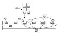
- FIGS. 1A through 1Care schematic block diagrams of an emissive display repair system.
- the system 100comprises an inspection subsystem 102 for inspecting an emissive substrate 104 with an array of wells 106 .
- emissive elements 108are located in the wells 106 , but not electrically connected to the emissive substrate 104 .
- the emissive elementsmay be located at predetermined array sites on a planar emissive substrate top surface.
- the emissive elements 108are deposited in the wells 106 via a fluidic assembly process, as explained in the parent applications listed in the RELATED APPLICATIONS Section, above.
- the wellsmay also be populated using a conventional robotic pick-and-place device.
- the purpose of the inspection subsystemis to determine defective array sites. Defective array sites 110 (circled in phantom) are shown.
- the defective array sitesare determined without the need for electrical (i.e., soldered) connections to the substrate, so that defective emissive elements 108 can be more easily replaced.
- System 100also comprises a pick-and-remove subsystem 112 for removing defect items 113 from the emissive substrate 104 .
- the emissive elements 108are light emitting diodes (LEDs).
- the inspection subsystem 102comprises an illuminator 116 for irradiating the emissive substrate 104 (or individual LEDs 108 ) with ultraviolet (UV) spectrum light and photoexciting the LEDs.
- a dual-mode image sensor 118identifies the presence of LEDs 108 through visual contrast and edge detection in one mode, while in another mode uses wavelength specific filtration to identify functional LEDs 108 by detecting the desired photoluminescence caused by photogenerated carriers.
- a UV laser, a UV LED, a xenon arc lamp, a mercury arc lamp, or a xenon mercury arc lampmay be used as the UV emission unit 110 .
- the LEDs 108have leakage current, light emission caused by the photoluminescence effect in the semiconductor layers occurs dominantly, as the recombination of excited electrons is non-emissive. If the LEDs 108 are not defective, the photoluminescence effect occurs in both the active layer and the semiconductor layers. In this case, light emission due to the photoluminescence effect in the active layer becomes dominant, and thus the light being generated has a different color than the defective LED. Hence, light having a predetermined wavelength is generated and thus allows the determination of whether an LED 108 is defective.
- the image sensor 118captures the wavelengths of light generated by defective, non-defective, and missing LEDs 108 , and compares the measurements to a predetermined standard.
- inspection imagingcan use spectroscopy instead of wavelength selective filters to more precisely quantify the photoluminescence of UV-excited LEDs.
- the inspection of LEDscan include a non-binary brightness assessment with a uniformity criterion to determine removal thresholds, and the inspection of LEDs can investigate red-blue-green (RGB) color balance per pixel for later correction.
- RGBred-blue-green
- a spectroscopegathers all the emitted light and records the distribution. This measurement generally does not include position data, as would be the case with a charge-coupled device (CCD) or CMOS sensor, so the position data must come from recording the xy (horizontal) position of the inspection head. This means that only one LED can be inspected at a time. In contrast, a bandgap filtered camera can inspect a larger field of view (but with less quantitation of wavelength).
- the predominant wavelengthis in the blue or green color spectrum, depending the LED doping.
- the predominant wavelengthis in the red color spectrum.
- the filtered image sensorcompares detected photoluminescence to a predetermined map cross-referencing position on the substrate to expected wavelengths. Wavelengths of light either missing or not matching the map of expected colors determine an array site to be defective. The inspection is done prior to the application of any color filter or color modification layers.
- the emissive substrate 102may be fabricated with one type (one color) of LED, two types (two colors) of LEDs, or three types (three colors) of LEDs.
- the image sensormay be replaced with a spectroscope enabling quantitative wavelength measurements through a necessarily smaller field of view.
- the filtered image sensor 118compares measured desired wavelength light intensity to a predetermined standard to determine if an LED is defective.
- the inspection subsystem 102determines defect items such as missing emissive elements (wells not populated by an emissive element), misaligned emissive elements (wells populated with an “upside-down” emissive element), mis-located (LEDs not located in a well), non-functional emissive elements, and debris (e.g., broken emissive elements, debris resulting from the fabrication of the emissive substrate, or solid objects in the fluidic assembly fluid).
- the pick-and-remove subsystem 112uses a robotic pick-and-remove device to remove these defect items 113 , as explained in more detail below, the robotic pick-and-place devices uses one of the following holding mechanisms: electrostatic, mechanical, and adhesive.
- the pick-and-remove deviceincludes a conventional optics/camera subsystem and/or a system for precisely measuring a destination (defect item) with respect to a known reference such as a substrate edge or corner.
- FIGS. 2A and 2Bare diagrams depicting an electrostatic pick-and-remove device.
- Microcomponent emissive elementsare held to a transfer head by creating an electrostatic charge on the transfer head that induces charge separation and attraction in the microcomponent. Release is achieved by removing the charge separation in the head.
- the electrostatic pick-and-remove device 200comprises a transfer head 202 capable of creating an electrostatic charge to attract a defect item 204 to the transfer head ( FIG. 2A ).
- Reference designator 206represents an attraction force due to the electrostatic charge.
- the electrostatic charge on the transfer head 202can be dissipated to release the defect item 204 ( FIG. 2B ).
- the transfer headis basically a capacitor concentrating charge on pick-up surface (protected by thin dielectric).
- a positive charge, for example, on transfer headattracts electrons to the LED top surface, creating a small attractive force. This process is effective because the emissive element has very little mass.
- FIGS. 3A through 3Fdepict an exemplary mechanical pick-and-remove device.
- the transfer pickup headmay be a thin, heatable metal tip connected to a stepper-controlled xyz (capable of movement in three dimensions) transfer head stage.
- the tipis coated with phase-change material and approaches the substrate surface at the location of the defect item to be removed, followed by resistive heating of the tip inducing melting of the coating material such that it contacts any components, fragments, or debris in the well or substrate top surface.
- the coating materialthen solidifies on cooling, removing any loose material from the site when the tip is removed.
- the material and coatingare removed in a bath or spray of solvent to dissolve the coating material and the tip is then recoated with fresh material by dipping in a liquid bath of the phase-change polymer.
- the transfer head 302is disposable and thrown out with the attached defect item 310 after use.
- a strong advantage of this approachis that the z-height (vertical) control near the defective array site may be relatively low precision as the phase change material will droop under gravity to make contact, and removes a wider variety of particle sizes and shapes than electrostatic or elastomeric adhesion.
- the mechanical forceis also capable of exceeding electrostatic or the elastomeric adhesive force.
- the mechanical pick-and-remove device 300comprises a thermal transfer head 302 with a liquid phase polymer coating 304 overlying the thermal transfer head.
- the thermal transfer head 302may be heated, as represented by voltage potential 306 ( FIG. 3A ), to convert a solid phase polymer to a liquid phase 308 or to maintain a polymer in its liquid phase.
- the defect itembecomes attached to the transfer head.
- the transfer head 303is cooled to convert the liquid phase polymer to a solid phase 312 attached to the defect item 310 .
- the transfer head 302is cleaned of the polymer with liquid 314 to remove the defect item
- FIG. 3Fthe transfer head 302 is recoated with a polymer 304 from a liquid phase polymer bath 316 .
- FIGS. 4A through 4Cdepict an adhesive pick-and-remove device.
- the defect item and the transfer headare natively adherent, with an overall binding strength scaling with interfacial area. Release is achieved by deflecting of the elastomeric surface which reduces contact area with the rigid defect item microcomponent, reducing the holding force between the transfer head and defect item.
- the adhesive pick-and-remove device 400comprises a transfer head 402 with a deformable contact surface area 404 .
- the contact surface area 404is adhesive, either natively so, or coated with an adhesive layer ( FIG. 4A ).
- the transfer head 402Since the transfer head 402 does not directly contact the surface of the emissive substrate 104 , the transfer head becomes adhesively attached a defect item 408 in response to expanding (deforming) the contact surface area size, as shown in FIG. 4B .
- the defect itemis released in response to bathing the transfer head in a solvent or increasing the deformation of transfer head to reduce the amount of surface area contacting the defect item (not shown).
- One variation of the adhesive approachis to coat the transfer head with a liquid, concomitant with the use of a substrate that does not retain any liquid after contact.
- a substratethat does not retain any liquid after contact.
- One exampleis a hydrophobic substrate surface and a polar liquid that holds the to-be-removed defect item through surface tension after contact.
- the repair system 100may further comprise a replacement subsystem.
- Empty wells 106 in the emissive substratecan be populated using a fluidic assembly process, or as shown, a repurposed pick-and-remove subsystem 120 .
- FIGS. 4A through 4Cmay also be interpreted as steps in the removal of a defective emissive element from a substrate well using a deformable elastomeric transfer head.
- the repair of fluidically assembled arrayscan be broadly reduced to two fundamental operations: the removal of emissive elements from the substrate, and the addition of replacement emissive elements into the emissive substrate wells.
- Removal of broken or nonfunctional components 408 from the wells 106requires the pick-and-remove transfer head 402 to overlap the alignment site (e.g., well) before intimate approach and pickup.
- the relative position of the transfer head 402 and emissive element component 408is not critical and can generally be achieved without additional positional feedback in the form of cameras or linear encoders.
- phase-change material-coated pickup headsare also efficacious at removal of broken components and debris from wells.
- the pick-and-remove xyz transfer head that was used for removalmay be repurposed and used to place new components.
- the addition processrequires significantly higher precision in placement than removal, so after new components are picked up from a staging area, the transfer head passes over an up-looking camera that corrects the relative position between the component center and the head center. For radially asymmetric components, angular orientation may also be corrected at this point.
- component depositionmay be achieved by de-energizing the electric field, but native stiction for microscale components may necessitate mechanically-assisted detachment.
- a compliant headcapable of deflecting, without damage to carried components, is located near the alignment site and lightly presses the component against the assembly surface. The head then translates the contacted component in the region of the recess such that the component is forced into the recess and mechanically retained as shown in FIGS. 5A through 5C . Due to the scale and brittle nature of the components, the down-force is carefully controlled and monitored such as with a piezoelectric force gauge in the pick-and-remove head. In this manner, without perfect knowledge and control over the relative positioning of the picked up component and the well, assembly can still be achieved.
- the final repair stepis a large-area clean that uses differential forcing to remove any out-of-place (mis-located) components from the substrate.
- the wellscomprise the alignment sites and in-field emissive element components are located on the substrate surface and not laterally confined by the wells.
- an adherent surface brought into close contact with the substrate surfaceexerts a significantly stronger force on an out-of-place components than the recessed correctly located components.
- This attractive forcemay be provided by coulombic, dielectrophoretic, or chemical adhesion.
- An additional approachleverages the lateral retention of the wells on correctly located components and provides a mechanical shear force on the substrate surface to dislodge mis-located components.
- the shear forcemay be provided by fluid flowing across the substrate or direct forcing provided by a brush or solid surface.
- a tilted substrate and gravitational forcingmay also be used to direct unretained components out of the assembly area into a collection trough.
- the substratemay be coupled to a directionally vibrating oscillator to reduce component stiction and the substrate may be covered in a carrier fluid to assist the transit of misaligned components.
- the form of non-fluidic and non-gravitational final clean-offmay be a cylinder that transits over the surface to remove mis-located components, a rigid sheet of dimensions comparable to the assembly substrate dimensions, a pliant sheet or brush of critical dimensions greater than the component's so as not to dislodge correctly located components while exerting shear force on the substrate surface, or a pliant natively adherent sheet such as, for example, polydimethylsiloxane (PDMS), which pulls mis-located components from the substrate when the sheet is peeled off.
- PDMSpolydimethylsiloxane
- the substrateis again inspected and verified that all alignment sites are occupied by intact and functional components and no residual out-of-place components remain on the substrate.
- FIGS. 5A through 5Cdepict an exemplary emissive element replacement process.
- a transfer head 500is shown with an attached replacement emissive element 502 .
- the transfer head 500positions the replacement emissive element 502 on the emissive substrate 104 top surface 504 at a location proximate to a well 106 to be populated ( FIG. 5A ).
- the transfer head 500translates the replacement emissive element 502 across top surface 504 , as represented by arrow 506 , over a well 106 opening, forcing the replacement emissive element into the well ( FIGS. 5B and 5C ).
- FIG. 6is a high-level repair process flowchart.
- the system disclosed hereinis a well suited for processes in which a relatively low number of defects resulting from fluidic self-assembly can be systematically identified and repaired.
- the emissive substrateis prepared, including a matrix of column and row lines needed to selectively enable individual emissive elements, and optionally including active matrix drive circuitry, as described in the parent applications listed in the RELATED APPLICATIONS Section, above.
- Step 602also includes the formation of wells in the emissive substrate top surface.
- a fluidic assembly processpositions emissive elements in the emissive substrate wells.
- an initial inspectionis preformed, using the inspection subsystem described in FIG. 1 .
- Inspection of each emissive element siteis necessary for verifying the occupancy of an intact and correctly oriented component. While inspection can be done with microscopy and digital image processing approaches which are standard in industrial electronics fabrication, emission can also be induced using UV radiation to additionally identify correctly located and aligned components that appear whole but are non-functional. Correctly located but misaligned devices are also considered non-functional.
- Step 608defective array sites are repaired.
- the output of the initial inspection test(Step 606 ) is a trinary array corresponding to known alignment sites and indicating if the site is: occupied by a functional component, occupied by a nonfunctional component, debris, or unoccupied.
- Step 608 aremoves nonfunctional components or debris from alignment sites. The successful execution of this step effectively creates an array with wells in a binary condition, describing sites that are either occupied by a functional component or empty.
- Step 608 bfills the unoccupied sites with functional components.
- the source of these componentsmay be the mis-located components from the field (substrate surface) or a reservoir of fresh emissive elements sufficiently spaced for individual pickup by a pick-and-remove device.
- both Steps 608 a and 608 bmay be accomplished by single-component pick-and-remove operations.
- the unoccupied wellsmay be filled using a second fluidic assembly process.
- Step 608 cresidual mis-located emissive elements are removed.
- a mis-located emissive elementoccupies a place on the emissive substrate outside of a well or assigned position on the substrate surface.
- fluidic assemblyStep 602
- deterministic control over individual component trajectoriesis not always possible, and after assembly, mis-located components may reside between wells on the receiving substrate surface.
- alignment sitesrepresent a small percentage of the total array area and identifying the location of individual mis-located components is both expensive and unnecessary.
- the residual mis-located componentsmay be removed in a single large-scale step that selects for mis-located components over correctly located components. For example, a brush, wiper, gas, or liquid can be applied to the emissive substrate top surface.
- Steps 608 b and 608 cmay be combined.
- Step 610The success of these repair steps is verified with a final inspection prior (Step 610 ), followed by the further integration of components to the receiving substrate in Step 612 . If this inspection reveals persisting defects in the array, the repair process is iterated accordingly.
- Step 606initial inspection
- Step 610full-substrate area in the final inspection
- two inspection methodsare presented: large-area inspection and site-by-site inspection. If the fluidically assembled components are micro-sized LEDs (uLEDs), having a diameter or cross-section of less than 100 microns, the fundamental mechanism behind both may be photoexcitation of the uLED with UV illumination and wavelength-selective measurement to identify the presence and function of correctly located uLEDs.
- uLEDsmicro-sized LEDs
- the imaging systemis either arrayed or transited over the assembly substrate surface and the processed image data is used to generate a matrix corresponding to the substrate alignment sites being functional, unoccupied, mis-located, occupied by nonfunctional components, or detecting debris.
- FIGS. 7A through 7Dare plan views of an exemplary emissive substrate following a fluidic assembly process. As integration relies on whole components for electrode contacts, broken but functional components are also removed.
- FIG. 7Adepicts the results of a visual inspection. As shown, most of the wells 106 are occupied with an emissive element 108 , but some wells are unoccupied. Assuming the emissive elements are LEDs, FIG. 7B depicts the result obtained in response to exposing the emissive substrate to UV radiation. Some sites 300 , marked with an “x” are occupied but do not respond with the expected intensity or wavelength, indicating the occupying LED is defective.
- FIG. 7Cdepicts wells 302 where defective LEDs are to be removed, and FIG. 7D depicts wells 304 to be repopulated with replacement LEDs.
- the repair toolis a 3-axis pick-and-remove head capable of handling microcomponents for repair of fluidic assembly's primary defect modes: missing components, misaligned components, and mis-located components residual on the substrate surface, and broken components occupying alignment sites.
- Industry standard pick-and-place operationsare conventionally performed with a pneumatic pressure-based holding force between head and component, which requires the vacuum port to be smaller than the component handling face.
- the vacuum-based approachbecomes less appropriate as the micro-scale port diameter restricts gas flow, creating significant pneumatic resistance that slows operation. Additionally, such small ports become susceptible to clogging.
- alternate handling approachesare desirable.
- the pick-and-remove transfer head contact facemay be smaller than the minimum array pitch (between wells) and larger than the emissive element contact face, so that it is capable of transferring single microcomponents.
- the method for holding components to the transfer headmay be electrostatic, mechanical, or adhesive.
- the transfer headmay incorporate a mechanical attachment such as microelectromechanical machine system (MEMS) tweezers, topographic retention features, or vacuum pulled through a microporous feature with pores significantly smaller than component dimensions.
- MEMSmicroelectromechanical machine system
- a 4-axis pick-and-place transfer headmay be used.
- FIGS. 8A and 8Bare a flowchart illustrating a method for repairing an emissive substrate. Although the method is depicted as a sequence of numbered steps for clarity, the numbering does not necessarily dictate the order of the steps. It should be understood that some of these steps may be skipped, performed in parallel, or performed without the requirement of maintaining a strict order of sequence. Generally however, the method follows the numeric order of the depicted steps. The method starts at Step 800 .
- Step 802provides an emissive substrate including an array of positioned emissive elements.
- Step 804inspects the emissive substrate to determine defective array sites.
- Step 806uses a pick-and remove process to remove defect items from the emissive substrate defective array sites.
- Step 810reinspects the emissive substrate to determine defective array sites, and subsequent to passing reinspection,
- Step 812anneals the emissive substrate.
- Step 814electrically connects the emissive elements to the emissive substrate.
- Step 802provides an emissive substrate with an array of wells, with emissive elements located in the wells, but not electrically connected to the emissive substrate. If the emissive elements are LEDs, inspecting the emissive substrate in Step 804 includes substeps. Step 804 a irradiates the emissive substrate with UV illumination. Step 804 b photoexcites the array of LED, and Step 804 c measures LED illumination at predetermined wavelengths to determine defective array sites.
- the defect itemsmay include misaligned emissive elements, mis-located emissive elements, non-functional emissive elements, or debris.
- Step 806uses the robotic pick-and-remove process to remove emissive elements from the defective array sites.
- the robotic pick-and-remove process usedmay use one of the following holding mechanisms: electrostatic, mechanical, or adhesive.
- Step 806 acreates an electrostatic charge between a pick-and-remove transfer head and a defect item.
- Step 806 battracts the defect item to the transfer head in response to the electrostatic charge, and
- Step 806 ceither removes (dissipates) the electrostatic charge to release the defect item from the transfer head, or the step disposes of the transfer head with attached defect item.
- Step 806 dcoats a pick-and-remove transfer head with a liquid polymer. Subsequent to contacting a defective emissive element with the transfer head, Step 806 e permits the transfer head to cool, Step 806 f converts the polymer to a solid phase attached to the defective emissive element. Step 806 g cleans the transfer head to remove the defective emissive element, and Step 806 h recoats the transfer head with a liquid phase polymer. Alternatively, Step 806 i discards the transfer head with the attached defect item.
- Step 806 jprovides a pick-and-remove deformable contact surface area transfer head that is adhesive with respect to a defective emissive element.
- Step 806 kexpands the transfer head deformable contact surface area to contact a defective emissive element, and in response to the contact, Step 806 l attaches the defective emissive element to the transfer head.
- the deformable contact surfacemay initially be a first flat surface area, and Step 806 k expands the transfer head deformable contact surface area to create a second convex surface area to contact a defective emissive element positioned in a substrate well.
- Step 806 mdiscards the defect item.
- Step 808populates empty wells with replacement emissive elements using a repurposed robotic pick-and-remove process as follows.
- Step 808 aattaches a replacement emissive element to a pick-and-remove transfer head.
- Step 808 bpositions the replacement emissive element on the emissive substrate top surface at a location proximate to a well to be populated.
- Step 808 ctranslates the replacement emissive element across top surface.
- Step 808 duses an elastic deformation force to direct the replacement emissive element into the well.
Landscapes
- Engineering & Computer Science (AREA)
- Microelectronics & Electronic Packaging (AREA)
- Power Engineering (AREA)
- Computer Hardware Design (AREA)
- Manufacturing & Machinery (AREA)
- Physics & Mathematics (AREA)
- Condensed Matter Physics & Semiconductors (AREA)
- General Physics & Mathematics (AREA)
- Electroluminescent Light Sources (AREA)
- Devices For Indicating Variable Information By Combining Individual Elements (AREA)
- Liquid Crystal (AREA)
Abstract
Description
Claims (18)
Priority Applications (30)
| Application Number | Priority Date | Filing Date | Title |
|---|---|---|---|
| US15/416,882US10446728B2 (en) | 2014-10-31 | 2017-01-26 | Pick-and remove system and method for emissive display repair |
| US15/440,735US10381335B2 (en) | 2014-10-31 | 2017-02-23 | Hybrid display using inorganic micro light emitting diodes (uLEDs) and organic LEDs (OLEDs) |
| US15/691,976US10535640B2 (en) | 2014-10-31 | 2017-08-31 | System and method for the fluidic assembly of micro-LEDs utilizing negative pressure |
| KR1020170118665AKR102042179B1 (en) | 2016-09-15 | 2017-09-15 | Pick-and-remove system and method for emissive display repair |
| CN201710833981.1ACN107833526B (en) | 2016-09-15 | 2017-09-15 | Pick-and-remove system and method of repairing illuminated displays |
| US15/722,037US10543486B2 (en) | 2014-10-31 | 2017-10-02 | Microperturbation assembly system and method |
| US15/838,536US10242977B2 (en) | 2014-10-31 | 2017-12-12 | Fluid-suspended microcomponent harvest, distribution, and reclamation |
| US15/849,859US10319878B2 (en) | 2014-10-31 | 2017-12-21 | Stratified quantum dot phosphor structure |
| US15/995,486US10333036B2 (en) | 2016-06-23 | 2018-06-01 | Absorptive color conversion film |
| US16/125,671US10516084B2 (en) | 2014-10-31 | 2018-09-08 | Encapsulated fluid assembly emissive elements |
| US16/406,196US10643981B2 (en) | 2014-10-31 | 2019-05-08 | Emissive display substrate for surface mount micro-LED fluidic assembly |
| US16/406,080US10804426B2 (en) | 2014-10-31 | 2019-05-08 | Planar surface mount micro-LED for fluidic assembly |
| US16/508,414US10811403B2 (en) | 2014-10-31 | 2019-07-11 | Method for fabricating a hybrid display using inorganic micro light emitting diodes (uLEDs) and organic LEDs (OLEDs) |
| US16/549,205US10985302B2 (en) | 2014-10-31 | 2019-08-23 | Pick-and-remove system with deformable contact surface |
| US16/595,623US10777714B2 (en) | 2014-10-31 | 2019-10-08 | Encapsulated emissive element for fluidic assembly |
| US16/693,674US10749083B2 (en) | 2014-10-31 | 2019-11-25 | Method for encapsulating emissive elements for fluidic assembly |
| US16/727,186US11145787B2 (en) | 2014-10-31 | 2019-12-26 | System and method for light emitting diode (LED) display repair |
| US16/737,353US11278900B2 (en) | 2014-10-31 | 2020-01-08 | Method for microperturbation assembly |
| US16/846,493US11251166B2 (en) | 2014-10-31 | 2020-04-13 | Fluidic assembly emissive display using axial light emitting diodes (LEDs) |
| US16/875,994US11296059B2 (en) | 2014-10-31 | 2020-05-16 | System and method for the selective harvest of emissive elements |
| US16/875,995US11315910B2 (en) | 2014-10-31 | 2020-05-16 | System and method for the characterization and dispersal of emissive elements |
| US16/984,491US12119432B2 (en) | 2014-10-31 | 2020-08-04 | Encapsulated light emitting diodes for selective fluidic assembly |
| US17/101,016US11894350B2 (en) | 2014-10-31 | 2020-11-23 | Fluidic assembly enabled mass transfer for microLED displays |
| US17/326,779US11908841B2 (en) | 2014-10-31 | 2021-05-21 | Back emission display |
| US17/464,892US11916163B2 (en) | 2014-10-31 | 2021-09-02 | System and method for the repair of serially connected display elements |
| US17/591,705US11929356B2 (en) | 2014-10-31 | 2022-02-03 | Emissive element harvest |
| US17/591,736US11855051B2 (en) | 2014-10-31 | 2022-02-03 | System for the characterization of emissive elements |
| US17/981,428US12230743B2 (en) | 2014-10-31 | 2022-11-06 | Fluidic assembly encapsulating light emitting diodes |
| US18/304,087US11990453B2 (en) | 2014-10-31 | 2023-04-20 | Fluidic assembly carrier substrate for microLED mass transfer |
| US18/406,849US12132034B2 (en) | 2014-10-31 | 2024-01-08 | Fluidic assembly MicroLED mass transfer method |
Applications Claiming Priority (13)
| Application Number | Priority Date | Filing Date | Title |
|---|---|---|---|
| US14/530,230US20150155445A1 (en) | 2011-12-27 | 2014-10-31 | Counterbore Pocket Structure for Fluidic Assembly |
| US14/680,618US10115862B2 (en) | 2011-12-27 | 2015-04-07 | Fluidic assembly top-contact LED disk |
| US14/749,569US9722145B2 (en) | 2015-06-24 | 2015-06-24 | Light emitting device and fluidic manufacture thereof |
| US15/158,556US9985190B2 (en) | 2016-05-18 | 2016-05-18 | Formation and structure of post enhanced diodes for orientation control |
| US15/190,813US9892944B2 (en) | 2016-06-23 | 2016-06-23 | Diodes offering asymmetric stability during fluidic assembly |
| US15/197,266US10249599B2 (en) | 2016-06-29 | 2016-06-29 | Laminated printed color conversion phosphor sheets |
| US15/221,571US9755110B1 (en) | 2016-07-27 | 2016-07-27 | Substrate with topological features for steering fluidic assembly LED disks |
| US15/266,796US9917226B1 (en) | 2016-09-15 | 2016-09-15 | Substrate features for enhanced fluidic assembly of electronic devices |
| US15/410,195US10236279B2 (en) | 2014-10-31 | 2017-01-19 | Emissive display with light management system |
| US15/410,001US9825202B2 (en) | 2014-10-31 | 2017-01-19 | Display with surface mount emissive elements |
| US15/413,053US10520769B2 (en) | 2014-10-31 | 2017-01-23 | Emissive display with printed light modification structures |
| US15/412,731US10418527B2 (en) | 2014-10-31 | 2017-01-23 | System and method for the fluidic assembly of emissive displays |
| US15/416,882US10446728B2 (en) | 2014-10-31 | 2017-01-26 | Pick-and remove system and method for emissive display repair |
Related Parent Applications (2)
| Application Number | Title | Priority Date | Filing Date |
|---|---|---|---|
| US15/412,731Continuation-In-PartUS10418527B2 (en) | 2014-10-31 | 2017-01-23 | System and method for the fluidic assembly of emissive displays |
| US15/413,053Continuation-In-PartUS10520769B2 (en) | 2014-10-31 | 2017-01-23 | Emissive display with printed light modification structures |
Related Child Applications (2)
| Application Number | Title | Priority Date | Filing Date |
|---|---|---|---|
| US15/440,735Continuation-In-PartUS10381335B2 (en) | 2014-10-31 | 2017-02-23 | Hybrid display using inorganic micro light emitting diodes (uLEDs) and organic LEDs (OLEDs) |
| US16/549,205DivisionUS10985302B2 (en) | 2014-10-31 | 2019-08-23 | Pick-and-remove system with deformable contact surface |
Publications (2)
| Publication Number | Publication Date |
|---|---|
| US20170140961A1 US20170140961A1 (en) | 2017-05-18 |
| US10446728B2true US10446728B2 (en) | 2019-10-15 |
Family
ID=58690304
Family Applications (2)
| Application Number | Title | Priority Date | Filing Date |
|---|---|---|---|
| US15/416,882Active2035-01-28US10446728B2 (en) | 2014-10-31 | 2017-01-26 | Pick-and remove system and method for emissive display repair |
| US16/549,205ActiveUS10985302B2 (en) | 2014-10-31 | 2019-08-23 | Pick-and-remove system with deformable contact surface |
Family Applications After (1)
| Application Number | Title | Priority Date | Filing Date |
|---|---|---|---|
| US16/549,205ActiveUS10985302B2 (en) | 2014-10-31 | 2019-08-23 | Pick-and-remove system with deformable contact surface |
Country Status (1)
| Country | Link |
|---|---|
| US (2) | US10446728B2 (en) |
Cited By (4)
| Publication number | Priority date | Publication date | Assignee | Title |
|---|---|---|---|---|
| US20220013400A1 (en)* | 2020-07-10 | 2022-01-13 | Samsung Electronics Co., Ltd. | Wet alignment method for micro-semiconductor chip and display transfer structure |
| WO2022034931A1 (en)* | 2020-08-10 | 2022-02-17 | 엘지전자 주식회사 | Substrate for manufacturing display device, and method for manufacturing display device using same |
| US20220254657A1 (en)* | 2019-07-16 | 2022-08-11 | Lg Electronics Inc. | Module for removing mis-assembled semiconductor light-emitting element and method for removing mis-assembled semiconductor light-emitting element by using same |
| US20230043559A1 (en)* | 2020-01-22 | 2023-02-09 | Lg Electronics Inc. | Apparatus and method for self-assembly of semiconductor light-emitting element |
Families Citing this family (30)
| Publication number | Priority date | Publication date | Assignee | Title |
|---|---|---|---|---|
| US10418527B2 (en)* | 2014-10-31 | 2019-09-17 | eLux, Inc. | System and method for the fluidic assembly of emissive displays |
| US10446728B2 (en)* | 2014-10-31 | 2019-10-15 | eLux, Inc. | Pick-and remove system and method for emissive display repair |
| US20180248342A1 (en)* | 2017-02-28 | 2018-08-30 | Hubbell Incorporated | Panels and enclosures with component positioning templates |
| US10453711B2 (en)* | 2017-05-31 | 2019-10-22 | Facebook Technologies, Llc | Fluidic pick-up head for small semiconductor devices |
| KR102236769B1 (en)* | 2017-07-18 | 2021-04-06 | 삼성전자주식회사 | Led module manufacturing device and method of manufacturing led module |
| CN107527973B (en)* | 2017-08-16 | 2019-05-28 | 深圳市华星光电技术有限公司 | Transfer device and micro-led transfer method |
| KR102430018B1 (en) | 2017-12-20 | 2022-08-05 | 엘지디스플레이 주식회사 | Transfer head assembly and light emitting device transfer apparatus |
| KR20190114334A (en)* | 2018-03-29 | 2019-10-10 | (주)포인트엔지니어링 | Inspection and repair method for micro led |
| KR102581137B1 (en) | 2018-08-29 | 2023-09-22 | 삼성디스플레이 주식회사 | Display device |
| DE102018125903A1 (en)* | 2018-10-18 | 2020-04-23 | Osram Opto Semiconductors Gmbh | Adhesive stamp and method for transferring missing semiconductor chips |
| KR102167268B1 (en)* | 2019-02-11 | 2020-10-19 | (주)에스티아이 | Device for removing defective led |
| TWI682531B (en)* | 2019-06-04 | 2020-01-11 | 友達光電股份有限公司 | Display apparatus and manufacturing method thereof |
| EP3998474A4 (en)* | 2019-07-09 | 2023-04-19 | LG Electronics Inc. | SYSTEM AND METHOD FOR AUTOMATIC DISPLAY PIXEL INSPECTION |
| US11784099B2 (en) | 2019-07-09 | 2023-10-10 | Mikro Mesa Technology Co., Ltd. | Method for replacing or patching element of display device |
| US20210015011A1 (en)* | 2019-07-09 | 2021-01-14 | Mikro Mesa Technology Co., Ltd. | Method for replacing or patching element of display device |
| WO2021025184A1 (en)* | 2019-08-05 | 2021-02-11 | 엘지전자 주식회사 | Module for removing misassembled semiconductor light-emitting element, and method using same to remove misassembled semiconductor light-emitting element |
| CN110600590B (en)* | 2019-09-25 | 2021-02-02 | 深圳市华星光电半导体显示技术有限公司 | Micro-LED transfer method and display panel |
| KR102802033B1 (en)* | 2019-10-15 | 2025-04-30 | 삼성전자주식회사 | Method for manufacturing display apparatus, interposer substrate and computer program stored in a recording medium |
| FR3103322B1 (en)* | 2019-11-15 | 2023-04-07 | Aledia | Method of manufacturing a set of light emitters |
| US11508780B2 (en) | 2020-01-14 | 2022-11-22 | Samsung Electronics Co., Ltd. | Method of manufacturing display apparatus, display apparatus, and structure for manufacturing display apparatus |
| KR102864796B1 (en) | 2020-02-24 | 2025-09-26 | 삼성디스플레이 주식회사 | Inspection device, inspection method and repair method of display panel using the same |
| CN111341710B (en)* | 2020-03-12 | 2022-12-06 | Tcl华星光电技术有限公司 | LED chip transfer system and LED chip transfer method |
| JP7438815B2 (en)* | 2020-03-27 | 2024-02-27 | 株式会社ジャパンディスプレイ | Array substrate, display device, and display device manufacturing method |
| CN115485835B (en)* | 2020-05-16 | 2025-09-16 | 伊乐视有限公司 | System and method for selectively collecting light-emitting elements |
| US12057331B2 (en) | 2020-07-13 | 2024-08-06 | Apple Inc. | High density pick and sequential place transfer process and tool |
| US11820651B2 (en)* | 2020-11-04 | 2023-11-21 | Apple Inc. | Mass transfer tool with high productivity |
| FR3119487B1 (en)* | 2021-01-29 | 2024-03-08 | Aledia | Method of manufacturing an electronic device and associated transfer device |
| US12394648B2 (en)* | 2021-03-02 | 2025-08-19 | Samsung Electronics Co., Ltd. | Display transfer structure including light emitting elements and transferring method of light emitting elements |
| US11856710B2 (en)* | 2022-05-25 | 2023-12-26 | Innolux Corporation | Method of manufacturing an electronic device |
| KR102787169B1 (en)* | 2022-09-06 | 2025-03-26 | 삼성전자주식회사 | Method for mass transfer of micro semiconductor chip and device used therefor |
Citations (206)
| Publication number | Priority date | Publication date | Assignee | Title |
|---|---|---|---|---|
| US4652757A (en)* | 1985-08-02 | 1987-03-24 | At&T Technologies, Inc. | Method and apparatus for optically determining defects in a semiconductor material |
| US5250843A (en)* | 1991-03-27 | 1993-10-05 | Integrated System Assemblies Corp. | Multichip integrated circuit modules |
| US5355577A (en)* | 1992-06-23 | 1994-10-18 | Cohn Michael B | Method and apparatus for the assembly of microfabricated devices |
| US5545291A (en)* | 1993-12-17 | 1996-08-13 | The Regents Of The University Of California | Method for fabricating self-assembling microstructures |
| US5594463A (en) | 1993-07-19 | 1997-01-14 | Pioneer Electronic Corporation | Driving circuit for display apparatus, and method of driving display apparatus |
| US5824186A (en)* | 1993-12-17 | 1998-10-20 | The Regents Of The University Of California | Method and apparatus for fabricating self-assembling microstructures |
| US5904545A (en) | 1993-12-17 | 1999-05-18 | The Regents Of The University Of California | Apparatus for fabricating self-assembling microstructures |
| US5954898A (en)* | 1994-05-13 | 1999-09-21 | Lockheed Fort Worth Company | Method and system for fabricating parts from composite materials |
| US5963662A (en)* | 1996-08-07 | 1999-10-05 | Georgia Tech Research Corporation | Inspection system and method for bond detection and validation of surface mount devices |
| US6246787B1 (en)* | 1996-05-31 | 2001-06-12 | Texas Instruments Incorporated | System and method for knowledgebase generation and management |
| US6274508B1 (en) | 1999-02-05 | 2001-08-14 | Alien Technology Corporation | Apparatuses and methods used in forming assemblies |
| US6281038B1 (en) | 1999-02-05 | 2001-08-28 | Alien Technology Corporation | Methods for forming assemblies |
| US6292582B1 (en)* | 1996-05-31 | 2001-09-18 | Lin Youling | Method and system for identifying defects in a semiconductor |
| US20010031514A1 (en)* | 1993-12-17 | 2001-10-18 | Smith John Stephen | Method and apparatus for fabricating self-assembling microstructures |
| US6316278B1 (en) | 1999-03-16 | 2001-11-13 | Alien Technology Corporation | Methods for fabricating a multiple modular assembly |
| US20020041149A1 (en)* | 2000-07-07 | 2002-04-11 | Tatsuya Shimoda | Organic EL display and manufacturing method thereof, multi-holed substrate, electro-optic device and manufacturing method thereof, and electronic device |
| US20020053065A1 (en)* | 2000-08-21 | 2002-05-02 | Kunihiro Mitsutake | Method, apparatus, and computer program of searching for clustering faults in semiconductor device manufacturing |
| US6417025B1 (en) | 2001-04-02 | 2002-07-09 | Alien Technology Corporation | Integrated circuit packages assembled utilizing fluidic self-assembly |
| US6420266B1 (en) | 1999-11-02 | 2002-07-16 | Alien Technology Corporation | Methods for creating elements of predetermined shape and apparatuses using these elements |
| US6468638B2 (en) | 1999-03-16 | 2002-10-22 | Alien Technology Corporation | Web process interconnect in electronic assemblies |
| US6479395B1 (en) | 1999-11-02 | 2002-11-12 | Alien Technology Corporation | Methods for forming openings in a substrate and apparatuses with these openings and methods for creating assemblies with openings |
| US6527964B1 (en) | 1999-11-02 | 2003-03-04 | Alien Technology Corporation | Methods and apparatuses for improved flow in performing fluidic self assembly |
| US6555408B1 (en) | 1999-02-05 | 2003-04-29 | Alien Technology Corporation | Methods for transferring elements from a template to a substrate |
| US6590346B1 (en) | 2001-07-16 | 2003-07-08 | Alien Technology Corporation | Double-metal background driven displays |
| US6599769B2 (en)* | 2000-06-30 | 2003-07-29 | Seiko Epson Corporation | Process for mounting device and optical transmission apparatus |
| US6606247B2 (en) | 2001-05-31 | 2003-08-12 | Alien Technology Corporation | Multi-feature-size electronic structures |
| US6613610B2 (en) | 2000-07-18 | 2003-09-02 | Sony Corporation | Image display unit and method of producing image display unit |
| US6618030B2 (en) | 1997-09-29 | 2003-09-09 | Sarnoff Corporation | Active matrix light emitting diode pixel structure and concomitant method |
| US6623579B1 (en) | 1999-11-02 | 2003-09-23 | Alien Technology Corporation | Methods and apparatus for fluidic self assembly |
| US20030186469A1 (en)* | 2002-01-24 | 2003-10-02 | Fonstad Clifton G. | Method and system for magnetically assisted statistical assembly of wafers |
| US6657289B1 (en) | 2001-07-13 | 2003-12-02 | Alien Technology Corporation | Apparatus relating to block configurations and fluidic self-assembly processes |
| US6665044B1 (en) | 1999-02-05 | 2003-12-16 | Alien Technology Corporation | Apparatuses and methods for forming electronic assemblies |
| US6683663B1 (en) | 1999-02-05 | 2004-01-27 | Alien Technology Corporation | Web fabrication of devices |
| US6687987B2 (en) | 2000-06-06 | 2004-02-10 | The Penn State Research Foundation | Electro-fluidic assembly process for integration of electronic devices onto a substrate |
| US20040045931A1 (en)* | 2002-01-23 | 2004-03-11 | Hill George Roland | Printing with differential adhesion |
| US6723576B2 (en) | 2000-06-30 | 2004-04-20 | Seiko Epson Corporation | Disposing method for semiconductor elements |
| US6731353B1 (en)* | 2001-08-17 | 2004-05-04 | Alien Technology Corporation | Method and apparatus for transferring blocks |
| US20040106334A1 (en)* | 2000-06-14 | 2004-06-03 | Tatsuo Suzuki | Microparticle arrangement film, electrical connection film, electrical connection structure, and microparticle arrangement method |
| US6756796B2 (en)* | 2002-08-09 | 2004-06-29 | Texas Instruments Incorporated | Method of search and identify reference die |
| US6780696B1 (en) | 2000-09-12 | 2004-08-24 | Alien Technology Corporation | Method and apparatus for self-assembly of functional blocks on a substrate facilitated by electrode pairs |
| US20040179145A1 (en)* | 1999-03-16 | 2004-09-16 | Jacobsen Jeffrey Jay | Apparatuses and methods for flexible displays |
| US20040222357A1 (en)* | 2002-05-22 | 2004-11-11 | King David Andrew | Optical excitation/detection device and method for making same using fluidic self-assembly techniques |
| US6825499B2 (en) | 2001-02-08 | 2004-11-30 | Sony Corporation | Display system and method of producing the same |
| US20040263830A1 (en)* | 2003-06-27 | 2004-12-30 | Canon Kabushiki Kaisha | Method and apparatus for inspecting semiconductor device |
| US20050047644A1 (en)* | 2003-09-03 | 2005-03-03 | Wong Soon Wei | Rotating prism component inspection system |
| US6863219B1 (en) | 2001-08-17 | 2005-03-08 | Alien Technology Corporation | Apparatuses and methods for forming electronic assemblies |
| US6870190B2 (en) | 2001-03-06 | 2005-03-22 | Sony Corporation | Display unit and semiconductor light emitting device |
| US20050176170A1 (en)* | 2001-03-02 | 2005-08-11 | Detig Robert H. | Process for the manufacture of large area arrays of discrete components |
| US20050196589A1 (en)* | 2004-01-21 | 2005-09-08 | Toshihiko Watanabe | Element arrangement board and element arrangement method |
| US20050206585A1 (en) | 2000-09-27 | 2005-09-22 | Stewart Roger G | Display devices and integrated circuits |
| US20050233504A1 (en) | 2003-03-06 | 2005-10-20 | Masato Doi | Device transfer method and display apparatus |
| US6984927B2 (en) | 2001-07-11 | 2006-01-10 | Sony Corporation | Display unit |
| US20060057293A1 (en)* | 2004-09-03 | 2006-03-16 | Eastman Kodak Company | Thermally controlled fluidic self-assembly |
| US7049227B2 (en) | 2002-01-17 | 2006-05-23 | Sony Corporation | Method for alloying a wiring portion for a image display device |
| US7049207B2 (en) | 2002-05-20 | 2006-05-23 | Sony Corporation | Isolating method and transferring method for semiconductor devices |
| US7080444B1 (en)* | 2002-02-28 | 2006-07-25 | Alien Technology Corporation | Apparatus for forming an electronic assembly |
| US20060164647A1 (en)* | 2005-01-13 | 2006-07-27 | Nagase & Co., Ltd. | Apparatus for marking a defect |
| US7087934B2 (en) | 2001-07-11 | 2006-08-08 | Sony Corporation | Semiconductor light emitting device, image display unit, lighting apparatus, and method of fabricating semiconductor light emitting device |
| US20060220989A1 (en)* | 2005-04-04 | 2006-10-05 | Hillis W D | Method of assembling displays on substrates |
| US20060223225A1 (en)* | 2005-03-29 | 2006-10-05 | Symbol Technologies, Inc. | Method, system, and apparatus for transfer of integrated circuit dies using an attractive force |
| US7122826B2 (en) | 2000-07-18 | 2006-10-17 | Sony Corporation | Image display unit |
| US20060232769A1 (en)* | 2003-03-26 | 2006-10-19 | Nikon Corporation | Defect inspection apparatus, defect inspection method and method of inspecting hole pattern |
| US7162035B1 (en)* | 2000-05-24 | 2007-01-09 | Tracer Detection Technology Corp. | Authentication method and system |
| US7179210B2 (en) | 2004-02-06 | 2007-02-20 | Soukeras John E | Club-weight(s) |
| US20070040688A1 (en)* | 2005-08-16 | 2007-02-22 | X-Cyte, Inc., A California Corporation | RFID inlays and methods of their manufacture |
| US7199527B2 (en) | 2000-11-21 | 2007-04-03 | Alien Technology Corporation | Display device and methods of manufacturing and control |
| US20070080703A1 (en)* | 2005-10-12 | 2007-04-12 | Delta Design, Inc. | Camera based pin grid array (PGA) inspection system with pin base mask and low angle lighting |
| US7223635B1 (en)* | 2003-07-25 | 2007-05-29 | Hrl Laboratories, Llc | Oriented self-location of microstructures with alignment structures |
| US7244326B2 (en) | 2003-05-16 | 2007-07-17 | Alien Technology Corporation | Transfer assembly for manufacturing electronic devices |
| US7250320B2 (en) | 2003-03-20 | 2007-07-31 | Sony Corporation | Semiconductor light emitting element, manufacturing method thereof, integrated semiconductor light emitting device, manufacturing method thereof, image display device, manufacturing method thereof, illuminating device and manufacturing method thereof |
| US20070224713A1 (en)* | 2006-03-21 | 2007-09-27 | Han In-Taek | Method of manufacturing display device using LED chips |
| US7317435B2 (en) | 2003-09-08 | 2008-01-08 | Tpo Displays Corp. | Pixel driving circuit and method for use in active matrix OLED with threshold voltage compensation |
| US7317211B2 (en) | 2003-03-14 | 2008-01-08 | Sony Corporation | Light-emitting device, light-emitting apparatus, image display apparatus, method of manufacturing light-emitting device, and method of manufacturing image display apparatus |
| US20080023435A1 (en)* | 2005-07-05 | 2008-01-31 | Enboa Wu | Method for self-assembling microstructures |
| US7353598B2 (en) | 2004-11-08 | 2008-04-08 | Alien Technology Corporation | Assembly comprising functional devices and method of making same |
| US20080181363A1 (en)* | 2007-01-25 | 2008-07-31 | Uchicago Argonne, Llc | Surface topography with X-ray reflection phase-contrast microscopy |
| US7452748B1 (en)* | 2004-11-08 | 2008-11-18 | Alien Technology Corporation | Strap assembly comprising functional block deposited therein and method of making same |
| US20090059204A1 (en)* | 2007-08-27 | 2009-03-05 | Harris Kevin M | Method and apparatus for inspecting objects using multiple images having varying optical properties |
| US20090136120A1 (en)* | 2007-11-23 | 2009-05-28 | Samsung Electro-Mechanics Co., Ltd. | Led inspection apparatus and led inspection method using the same |
| US7542301B1 (en) | 2005-06-22 | 2009-06-02 | Alien Technology Corporation | Creating recessed regions in a substrate and assemblies having such recessed regions |
| US7564064B2 (en) | 2002-09-06 | 2009-07-21 | Sony Corporation | Semiconductor light emitting device, an integrated semiconductor light emitting apparatus, an image display apparatus, and an illuminating apparatus having a semiconductor layer with conical crystal portion |
| US7573194B2 (en) | 2005-05-09 | 2009-08-11 | Sony Corporation | Display apparatus and method of manufacturing display apparatus |
| US7572649B2 (en) | 2005-05-20 | 2009-08-11 | Sony Corporation | Device transferring system, device transferring method, and display manufacturing method |
| US7576656B2 (en) | 2005-09-15 | 2009-08-18 | Alien Technology Corporation | Apparatuses and methods for high speed bonding |
| US20090218260A1 (en)* | 2008-03-03 | 2009-09-03 | Palo Alto Research Center, Incorporated | Micro-assembler |
| US7589355B2 (en) | 2005-06-10 | 2009-09-15 | Sony Corporation | Light emitting diode, method of manufacturing light emitting diode, light emitting diode backlight, light emitting diode illuminating device, light emitting diode display, and electronic apparatus |
| US7619598B2 (en) | 2004-04-08 | 2009-11-17 | Stmicroelectronics S.R.L. | Driver for an OLED passive-matrix display |
| US20100122654A1 (en)* | 2004-12-22 | 2010-05-20 | Ravi Sharma | Thermally controlled fluidic self-assembly |
| US7723764B2 (en) | 2001-06-12 | 2010-05-25 | Sony Corporation | Device mounting substrate and image display device |
| US7763901B2 (en) | 2006-12-04 | 2010-07-27 | Sony Corporation | Electronic device, method of producing the same, light-emitting diode display unit, and method of producing the same |
| US20100186883A1 (en) | 2009-01-29 | 2010-07-29 | Sony Corporation | Method of transferring a device and method of manufacturing a display apparatus |
| US7774929B2 (en) | 2006-03-14 | 2010-08-17 | Regents Of The University Of Minnesota | Method of self-assembly on a surface |
| US7795629B2 (en) | 2008-05-12 | 2010-09-14 | Sony Corporation | Light-emitting diode display and method for manufacturing the same |
| US7838410B2 (en) | 2007-07-11 | 2010-11-23 | Sony Corporation | Method of electrically connecting element to wiring, method of producing light-emitting element assembly, and light-emitting element assembly |
| US20100317132A1 (en)* | 2009-05-12 | 2010-12-16 | Rogers John A | Printed Assemblies of Ultrathin, Microscale Inorganic Light Emitting Diodes for Deformable and Semitransparent Displays |
| US7884543B2 (en) | 2006-10-12 | 2011-02-08 | Sony Corporation | Method of forming wiring of light emitting device, substrate for mounting light emitting device, display, back light, illuminating apparatus and electronic appliance |
| US7927976B2 (en) | 2008-07-23 | 2011-04-19 | Semprius, Inc. | Reinforced composite stamp for dry transfer printing of semiconductor elements |
| US7968474B2 (en) | 2006-11-09 | 2011-06-28 | Nanosys, Inc. | Methods for nanowire alignment and deposition |
| US20110159412A1 (en)* | 2009-12-28 | 2011-06-30 | Hynix Semiconductor Inc. | Method of correcting defect in euv mask |
| US7977130B2 (en) | 2006-08-03 | 2011-07-12 | The Invention Science Fund I, Llc | Method of assembling displays on substrates |
| US20110205544A1 (en)* | 2008-06-10 | 2011-08-25 | University Of Maryland - Office Of Technoogy | Fast sar assessment and certification system for wireless device certification |
| US20110249111A1 (en)* | 2010-03-18 | 2011-10-13 | Tommy Weiss | Process control and manufacturing method for fan out wafers |
| US20110266039A1 (en) | 2010-04-28 | 2011-11-03 | Sony Corporation | Method of mounting devices in substrate and device-mounting substrate structure thereof |
| US20110273410A1 (en) | 2010-05-07 | 2011-11-10 | Snu R&Db Foundation | Led display apparatus having active devices and fabrication method thereof |
| US20110277917A1 (en)* | 2010-03-19 | 2011-11-17 | Panasonic Corporation | Method for disposing a microstructure |
| US8101457B2 (en) | 2006-07-12 | 2012-01-24 | Sony Corporation | Mounting method, mounted structure, manufacturing method for electronic equipment, electronic equipment, manufacturing method for light-emitting diode display, and light-emitting diode display |
| US20120028342A1 (en)* | 2009-03-24 | 2012-02-02 | Ismagilov Rustem F | Slip chip device and methods |
| US20120056340A1 (en)* | 2010-09-03 | 2012-03-08 | Nitto Denko Corporation | Method of producing roll of laminate strip with polarizing film |
| CN102522553A (en) | 2011-12-31 | 2012-06-27 | 武汉大学 | Sodium ion battery positive material |
| US20120169786A1 (en) | 2011-01-05 | 2012-07-05 | Sony Corporation | Light emitting device, illuminating device, and display device |
| US8222659B2 (en) | 2008-12-12 | 2012-07-17 | Sony Corporation | Semiconductor light-emitting device and method for manufacturing the same |
| US8232640B2 (en) | 2006-07-18 | 2012-07-31 | Sony Corporation | Device, method of manufacturing device, board, method of manufacturing board, mounting structure, mounting method, LED display, LED backlight and electronic device |
| US20120218318A1 (en) | 2011-02-24 | 2012-08-30 | Sony Corporation | Light emitting apparatus, illumination apparatus and display apparatus |
| US20120229805A1 (en)* | 2011-03-08 | 2012-09-13 | Semiconductor Energy Laboratory Co., Ltd. | Defect evaluation method for semiconductor |
| US8284120B2 (en) | 2005-03-11 | 2012-10-09 | The Invention Science Fund I, Llc | Self assembly of elements for displays |
| US8300007B2 (en)* | 2005-03-11 | 2012-10-30 | The Invention Science Fund I, Llc | Self assembling display with substrate |
| US20120285010A1 (en)* | 2011-05-10 | 2012-11-15 | Imec | Method and apparatus for fluid guided self-assembly of microcomponents |
| US8333860B1 (en) | 2011-11-18 | 2012-12-18 | LuxVue Technology Corporation | Method of transferring a micro device |
| US8349116B1 (en)* | 2011-11-18 | 2013-01-08 | LuxVue Technology Corporation | Micro device transfer head heater assembly and method of transferring a micro device |
| US8361268B2 (en) | 2009-04-10 | 2013-01-29 | Sony Corporation | Method of transferring device |
| US8361297B2 (en) | 2008-01-11 | 2013-01-29 | The Penn State Research Foundation | Bottom-up assembly of structures on a substrate |
| US8379003B2 (en) | 2007-08-03 | 2013-02-19 | Sony Corporation | Display device and wiring routing method |
| US8384630B2 (en)* | 2007-05-31 | 2013-02-26 | Nthdegree Technologies Worldwide Inc | Light emitting, photovoltaic or other electronic apparatus and system |
| US8384116B2 (en) | 2008-11-20 | 2013-02-26 | Sony Corporation | Substrate with chips mounted thereon, method of manufacturing substrate with chips mounted thereon, display, and method of manufacturing display |
| US8383506B1 (en) | 2012-07-06 | 2013-02-26 | LuxVue Technology Corporation | Method of forming a compliant monopolar micro device transfer head with silicon electrode |
| US8390537B2 (en)* | 2005-03-11 | 2013-03-05 | The Invention Science Fund I, Llc | Method of assembling displays on substrates |
| US8415879B2 (en) | 2007-05-31 | 2013-04-09 | Nthdegree Technologies Worldwide Inc | Diode for a printable composition |
| US8415771B1 (en) | 2012-05-25 | 2013-04-09 | LuxVue Technology Corporation | Micro device transfer head with silicon electrode |
| US8415767B1 (en) | 2012-07-06 | 2013-04-09 | LuxVue Technology Corporation | Compliant bipolar micro device transfer head with silicon electrodes |
| US8415768B1 (en) | 2012-07-06 | 2013-04-09 | LuxVue Technology Corporation | Compliant monopolar micro device transfer head with silicon electrode |
| US8426227B1 (en) | 2011-11-18 | 2013-04-23 | LuxVue Technology Corporation | Method of forming a micro light emitting diode array |
| US20130100089A1 (en)* | 2011-10-20 | 2013-04-25 | Sharp Laboratories Of America, Inc. | Newton ring mura detection system |
| US20130122633A1 (en)* | 2011-06-16 | 2013-05-16 | Panasonic Corporation | Method for fabricating solar cell comprising condenser lens and photoelectric conversion element |
| US8476826B2 (en) | 2009-04-10 | 2013-07-02 | Sony Corporation | Manufacturing method of display device and display device |
| US20130187540A1 (en)* | 2012-01-24 | 2013-07-25 | Michael A. Tischler | Discrete phosphor chips for light-emitting devices and related methods |
| US20130210194A1 (en)* | 2012-02-09 | 2013-08-15 | LuxVue Technology Corporation | Method of transferring and bonding an array of micro devices |
| US8518204B2 (en) | 2011-11-18 | 2013-08-27 | LuxVue Technology Corporation | Method of fabricating and transferring a micro device and an array of micro devices utilizing an intermediate electrically conductive bonding layer |
| US8569115B1 (en) | 2012-07-06 | 2013-10-29 | LuxVue Technology Corporation | Method of forming a compliant bipolar micro device transfer head with silicon electrodes |
| US8570482B2 (en)* | 2005-03-11 | 2013-10-29 | The Invention Science Fund I, Llc | Self assembly of elements for displays |
| US8573469B2 (en) | 2011-11-18 | 2013-11-05 | LuxVue Technology Corporation | Method of forming a micro LED structure and array of micro LED structures with an electrically insulating layer |
| US20140002128A1 (en)* | 2012-06-27 | 2014-01-02 | Texas Instruments Incorporated | Die Attach Pick Error Detection |
| US20140008691A1 (en) | 2012-07-04 | 2014-01-09 | Sony Corporation | Device and electronic apparatus |
| US8648328B2 (en) | 2011-12-27 | 2014-02-11 | Sharp Laboratories Of America, Inc. | Light emitting diode (LED) using three-dimensional gallium nitride (GaN) pillar structures with planar surfaces |
| US20140080261A1 (en)* | 2012-03-28 | 2014-03-20 | Panasonic Corporation | Method for fabricating a chip having a water-repellent obverse surface and a hydrophilic reverse surface |
| US8683416B1 (en) | 2011-07-28 | 2014-03-25 | Juniper Networks, Inc. | Integrated circuit optimization |
| US20140084482A1 (en) | 2012-09-24 | 2014-03-27 | LuxVue Technology Corporation | Micro device stabilization post |
| US8686447B2 (en) | 2011-03-01 | 2014-04-01 | Sony Corporation | Light emitting unit and display device |
| US8685774B2 (en) | 2011-12-27 | 2014-04-01 | Sharp Laboratories Of America, Inc. | Method for fabricating three-dimensional gallium nitride structures with planar surfaces |
| US8696818B2 (en)* | 2007-09-17 | 2014-04-15 | Rave Llc | Debris removal in high aspect structures |
| US20140119796A1 (en)* | 2012-10-29 | 2014-05-01 | Alan Richard Priebe | Fixing toner using heating-liquid-blocking barrier |
| US20140175481A1 (en)* | 2012-01-24 | 2014-06-26 | Michael A. Tischler | Wafer-level flip chip device packages and related methods |
| US8791474B1 (en)* | 2013-03-15 | 2014-07-29 | LuxVue Technology Corporation | Light emitting diode display with redundancy scheme |
| US20140210995A1 (en)* | 2013-01-31 | 2014-07-31 | Nichia Corporation | Inspection method for semiconductor light-emitting device and manufacturing method for semiconductor light-emitting device |
| US8809126B2 (en) | 2007-05-31 | 2014-08-19 | Nthdegree Technologies Worldwide Inc | Printable composition of a liquid or gel suspension of diodes |
| US20140234994A1 (en)* | 2013-02-18 | 2014-08-21 | Nichia Corporation | Inspection method for semiconductor light-emitting device and manufacturing method for semiconductor light-emitting device |
| US20140277680A1 (en) | 2013-03-15 | 2014-09-18 | John S. Youngquist | Auto-setup control process |
| US8846457B2 (en) | 2007-05-31 | 2014-09-30 | Nthdegree Technologies Worldwide Inc | Printable composition of a liquid or gel suspension of diodes |
| US20140302312A1 (en)* | 2013-03-14 | 2014-10-09 | New Jersey Institute Of Technology | System and method for formation of thin films with self-assembled monolayers embedded on their surfaces |
| US20140306244A1 (en)* | 2013-04-15 | 2014-10-16 | Nthdegree Technologies Worldwide Inc. | Conductive phosphor layer electrode for vertical led |
| US8896907B2 (en)* | 2009-11-06 | 2014-11-25 | Sharp Laboratories Of America, Inc. | Plasmonic reflective display fabricated using anodized aluminum oxide |
| US8906713B2 (en) | 2012-03-30 | 2014-12-09 | Nthdegree Technologies Worldwide Inc. | LED lamp using blue and cyan LEDs and a phosphor |
| US20150179877A1 (en) | 2013-12-20 | 2015-06-25 | LuxVue Technology Corporation | Nanowire device |
| US20150214430A1 (en)* | 2011-12-27 | 2015-07-30 | Sharp Laboratories Of America, Inc. | Fluidic Assembly Top-Contact LED Disk |
| US20150263066A1 (en)* | 2014-03-13 | 2015-09-17 | LuxVue Technology Corporation | Led device with embedded nanowire leds |
| US20150325438A1 (en)* | 2014-05-09 | 2015-11-12 | Samsung Electronics Co., Ltd. | Precursor solution for forming metal chalcogenide film |
| US9240397B2 (en) | 2013-06-17 | 2016-01-19 | LuxVue Technology Corporation | Method for integrating a light emitting device |
| US9252375B2 (en) | 2013-03-15 | 2016-02-02 | LuxVue Technology Corporation | Method of fabricating a light emitting diode display with integrated defect detection test |
| US9269322B2 (en) | 2006-01-09 | 2016-02-23 | Ignis Innovation Inc. | Method and system for driving an active matrix display circuit |
| US9293476B2 (en) | 2011-11-23 | 2016-03-22 | Globalfoundries Inc. | Integrating active matrix inorganic light emitting diodes for display devices |
| US20160086534A1 (en) | 2014-09-19 | 2016-03-24 | Kopin Corporation | Active matrix led pixel driving circuit and layout method |
| US9305807B2 (en) | 2014-02-27 | 2016-04-05 | Palo Alto Research Center Incorporated | Fabrication method for microelectronic components and microchip inks used in electrostatic assembly |
| US9318475B2 (en) | 2014-05-15 | 2016-04-19 | LuxVue Technology Corporation | Flexible display and method of formation with sacrificial release layer |
| US9343448B2 (en) | 2012-12-10 | 2016-05-17 | LuxVue Technology Corporation | Active matrix emissive micro LED display |
| US20160155892A1 (en)* | 2014-11-27 | 2016-06-02 | Sct Technology, Ltd. | Method for manufacturing a light emitted diode display |
| US9378993B2 (en)* | 2011-11-18 | 2016-06-28 | Fuji Machine Mfg. Co., Ltd. | Wafer-related data management method and wafer-related data creation device |
| US20160263632A1 (en)* | 2007-09-17 | 2016-09-15 | Rave Llc | Debris removal in high aspect structures |
| US20160266165A1 (en)* | 2007-09-17 | 2016-09-15 | Rave Llc | Debris removal from high aspect structures |
| US9531002B2 (en)* | 2012-03-28 | 2016-12-27 | Sharp Laboratories Of America, Inc. | Transition metal cyanometallate cathode battery with metal plating anode |
| US9534772B2 (en)* | 2007-05-31 | 2017-01-03 | Nthdegree Technologies Worldwide Inc | Apparatus with light emitting diodes |
| US9554484B2 (en)* | 2012-03-30 | 2017-01-24 | The Board Of Trustees Of The University Of Illinois | Appendage mountable electronic devices conformable to surfaces |
| US20170062393A1 (en)* | 2015-08-31 | 2017-03-02 | Samsung Display Co., Ltd. | Display device and method of manufacturing the same |
| US9627437B1 (en)* | 2016-06-30 | 2017-04-18 | Sharp Laboratories Of America, Inc. | Patterned phosphors in through hole via (THV) glass |
| US9647029B2 (en)* | 2015-10-12 | 2017-05-09 | Industrial Technology Research Institute | Light-emitting device and manufacturing method of a display |
| US20170133550A1 (en)* | 2014-10-31 | 2017-05-11 | eLux Inc. | Display with surface mount emissive elements |
| US20170133558A1 (en)* | 2014-10-31 | 2017-05-11 | eLux Inc. | System and Method for the Fluidic Assembly of Emissive Displays |
| US20170139276A1 (en)* | 2014-10-31 | 2017-05-18 | eLux Inc. | Emissive Display with Printed Light Modification Structures |
| US20170140961A1 (en)* | 2014-10-31 | 2017-05-18 | eLux Inc. | Pick-and-Remove System and Method for Emissive Display Repair |
| US20170179092A1 (en)* | 2014-10-31 | 2017-06-22 | eLux Inc. | Hybrid Display using Inorganic Micro Light Emitting Diodes (uLEDs) and Organic LEDs (OLEDs) |
| US20170215280A1 (en)* | 2016-01-21 | 2017-07-27 | Vuereal Inc. | Selective transfer of micro devices |
| US9755110B1 (en)* | 2016-07-27 | 2017-09-05 | Sharp Laboratories Of America, Inc. | Substrate with topological features for steering fluidic assembly LED disks |
| US20170330855A1 (en)* | 2016-05-13 | 2017-11-16 | Taiwan Semiconductor Manufacturing Company, Ltd. | System and Method for Immersion Bonding |
| US20170338389A1 (en)* | 2016-05-18 | 2017-11-23 | Sharp Laboratories Of America, Inc. | Formation and Structure of Post Enhanced Diodes for Orientation Control |
| US9837390B1 (en)* | 2016-11-07 | 2017-12-05 | Corning Incorporated | Systems and methods for creating fluidic assembly structures on a substrate |
| US20170365755A1 (en)* | 2016-05-25 | 2017-12-21 | Chen-Fu Chu | Methods of filling an organic or inorganic liquid in an assembly module |
| US20170372927A1 (en)* | 2016-06-23 | 2017-12-28 | Sharp Laboratories Of America, Inc. | Diodes offering asymmetric stability during fluidic assembly |
| US20180012873A1 (en)* | 2014-10-31 | 2018-01-11 | eLux Inc. | System and Method for the Fluidic Assembly of Micro-LEDs Utilizing Negative Pressure |
| US20180029038A1 (en)* | 2014-10-31 | 2018-02-01 | eLux Inc. | Microperturbation Assembly System and Method |
| US9917226B1 (en)* | 2016-09-15 | 2018-03-13 | Sharp Kabushiki Kaisha | Substrate features for enhanced fluidic assembly of electronic devices |
| US20180076168A1 (en)* | 2016-09-13 | 2018-03-15 | Sharp Laboratories Of America, Inc. | Fluidic Self Assembly of Contact Materials |
| US20180076068A1 (en)* | 2016-09-09 | 2018-03-15 | Sharp Laboratories Of America, Inc. | Fluidic Assembly Using Tunable Suspension Flow |
| US20180102352A1 (en)* | 2014-10-31 | 2018-04-12 | eLux Inc. | Fluid-Suspended Microcomponent Harvest, Distribution, and Reclamation |
| US20180138359A1 (en)* | 2014-10-31 | 2018-05-17 | eLux Inc. | Stratified Quantum Dot Phosphor Structure |
| US20180190672A1 (en)* | 2017-01-03 | 2018-07-05 | Innolux Corporation | Display device |
| US20180198032A1 (en)* | 2015-08-18 | 2018-07-12 | Jiangsu Cherrity Optronics Co., Ltd. | Process Method for Refining Photoconverter to Bond-Package LED and Refinement Equipment System |
| US20180204973A1 (en)* | 2016-03-23 | 2018-07-19 | Korea Photonics Technology Institute | Light-emitting diode structure, transfer assembly, and transfer method using the same |
| US10236279B2 (en)* | 2014-10-31 | 2019-03-19 | eLux, Inc. | Emissive display with light management system |
Family Cites Families (71)
| Publication number | Priority date | Publication date | Assignee | Title |
|---|---|---|---|---|
| US4597815A (en)* | 1980-11-29 | 1986-07-01 | Nissha Printing Co., Ltd. | Transfer printing |
| US4752180A (en)* | 1985-02-14 | 1988-06-21 | Kabushiki Kaisha Toshiba | Method and apparatus for handling semiconductor wafers |
| DE3912242A1 (en)* | 1989-04-14 | 1990-10-18 | Gurit Essex Ag | DEVICES FOR MACHINE APPLICATION OF FLEXIBLE, ONE-SIDED ADHESIVE LAYER BODIES TO WORKPIECES AND USE THEREOF |
| JPH0744135B2 (en)* | 1989-08-28 | 1995-05-15 | 株式会社東芝 | Bonding method and bonding device for semiconductor substrate |
| EP0642910A1 (en)* | 1992-12-27 | 1995-03-15 | Nissha Printing Co., Ltd. | Insert molded article, and apparatus and method for producing the insert molded article |
| US5524765A (en)* | 1994-11-15 | 1996-06-11 | Tempo G | Carrier tape packaging system utilizing a layer of gel for retaining small components |
| US5542601A (en)* | 1995-02-24 | 1996-08-06 | International Business Machines Corporation | Rework process for semiconductor chips mounted in a flip chip configuration on an organic substrate |
| SG54995A1 (en)* | 1996-01-31 | 1998-12-21 | Texas Instr Singapore Pet Ltd | Method and apparatus for aligning the position of die on a wafer table |
| JPH11286105A (en)* | 1998-04-01 | 1999-10-19 | Sony Corp | Recording method and recorder |
| US6193143B1 (en)* | 1998-08-05 | 2001-02-27 | Matsushita Electric Industrial Co., Ltd. | Solder bump forming method and mounting apparatus and mounting method of solder ball |
| US6595408B1 (en)* | 1998-10-07 | 2003-07-22 | Micron Technology, Inc. | Method of attaching solder balls to BGA package utilizing a tool to pick and dip the solder ball in flux prior to placement |
| JP2000150560A (en)* | 1998-11-13 | 2000-05-30 | Seiko Epson Corp | Bump forming method and bump forming bonding tool, semiconductor wafer, semiconductor chip and semiconductor device, and their manufacturing method, circuit board, and electronic equipment |
| JP3504543B2 (en)* | 1999-03-03 | 2004-03-08 | 株式会社日立製作所 | Semiconductor device separation method and device, and semiconductor device mounting method |
| JP3798597B2 (en)* | 1999-11-30 | 2006-07-19 | 富士通株式会社 | Semiconductor device |
| GB2360730B (en)* | 2000-03-31 | 2004-09-22 | Bausch & Lomb Uk Ltd | Apparatus and method for separating contact lens molds |
| TWI283906B (en)* | 2001-12-21 | 2007-07-11 | Esec Trading Sa | Pick-up tool for mounting semiconductor chips |
| US6773543B2 (en)* | 2002-05-07 | 2004-08-10 | Delaware Capital Formation, Inc. | Method and apparatus for the multiplexed acquisition of a bare die from a wafer |
| CN100401486C (en)* | 2002-08-09 | 2008-07-09 | 富士通株式会社 | Semiconductor device and method for manufacturing the same |
| US7182118B2 (en)* | 2003-06-02 | 2007-02-27 | Asm Assembly Automation Ltd. | Pick and place assembly for transporting a film of material |
| JP2005055330A (en)* | 2003-08-06 | 2005-03-03 | Elpida Memory Inc | Pressure device for semiconductor device |
| US7408566B2 (en)* | 2003-10-22 | 2008-08-05 | Oki Data Corporation | Semiconductor device, LED print head and image-forming apparatus using same, and method of manufacturing semiconductor device |
| US7650688B2 (en)* | 2003-12-31 | 2010-01-26 | Chippac, Inc. | Bonding tool for mounting semiconductor chips |
| JP2006222222A (en)* | 2005-02-09 | 2006-08-24 | Canon Inc | Projection optical system and exposure apparatus having the same |
| TWI276598B (en)* | 2006-03-09 | 2007-03-21 | Hi Touch Imaging Tech Co Ltd | Paper fetch device using a sucking disc for adhering to paper |
| KR100777784B1 (en)* | 2006-04-07 | 2007-11-21 | 한미반도체 주식회사 | Package handler |
| JP2007287779A (en)* | 2006-04-13 | 2007-11-01 | Matsushita Electric Ind Co Ltd | Electronic component mounting system, mounting state inspection apparatus, and electronic component mounting method |
| EP2023185B1 (en)* | 2006-05-16 | 2012-08-15 | Sharp Kabushiki Kaisha | Process for manufacturing display panel, display panel manufacturing apparatus and display panel |
| TWI309444B (en)* | 2006-05-23 | 2009-05-01 | Advanced Semiconductor Eng | Die pick-up apparatus |
| US7476568B2 (en)* | 2006-06-30 | 2009-01-13 | Intel Corporation | Wafer-level assembly of heat spreaders for dual IHS packages |
| US8037918B2 (en)* | 2006-12-04 | 2011-10-18 | Stats Chippac, Inc. | Pick-up heads and systems for die bonding and related applications |
| MY152599A (en)* | 2007-02-14 | 2014-10-31 | Eles Semiconductor Equipment S P A | Test of electronic devices at package level using test boards without sockets |
| JP5196838B2 (en)* | 2007-04-17 | 2013-05-15 | リンテック株式会社 | Manufacturing method of chip with adhesive |
| TWI463580B (en)* | 2007-06-19 | 2014-12-01 | Renesas Electronics Corp | Manufacturing method of semiconductor integrated circuit device |
| US10618080B2 (en)* | 2007-09-17 | 2020-04-14 | Bruker Nano, Inc. | Debris removal from high aspect structures |
| WO2009099644A1 (en)* | 2008-02-08 | 2009-08-13 | Heartware, Inc. | Ventricular assist device for intraventricular placement |
| US8012866B2 (en)* | 2008-05-30 | 2011-09-06 | Asm Assembly Automation Ltd | Method of bonding semiconductor devices utilizing solder balls |
| ITMI20081023A1 (en)* | 2008-06-04 | 2009-12-05 | Eles Semiconductor Equipment Spa | TESTING OF ELECTRONIC DEVICES WITH BOARDS WITHOUT SOCKETS BASED ON MAGNETIC LOCKING |
| TWI385743B (en)* | 2008-12-31 | 2013-02-11 | Cheng Mei Instr Co Ltd | System and method for separating defective dies from a wafer |
| US8860043B2 (en)* | 2009-06-05 | 2014-10-14 | Cree, Inc. | Light emitting device packages, systems and methods |
| US7989266B2 (en)* | 2009-06-18 | 2011-08-02 | Aptina Imaging Corporation | Methods for separating individual semiconductor devices from a carrier |
| EP2296168A1 (en)* | 2009-09-09 | 2011-03-16 | Kulicke & Soffa Die Bonding GmbH | Tool for picking a planar object from a supply station |
| BR112012028236A2 (en)* | 2010-05-03 | 2017-03-14 | A Raymond Et Cie | method and device for placing adhesive element in an array |
| US9478719B2 (en)* | 2010-11-08 | 2016-10-25 | Bridgelux, Inc. | LED-based light source utilizing asymmetric conductors |
| US9299674B2 (en)* | 2012-04-18 | 2016-03-29 | Taiwan Semiconductor Manufacturing Company, Ltd. | Bump-on-trace interconnect |
| US9105492B2 (en)* | 2012-05-08 | 2015-08-11 | LuxVue Technology Corporation | Compliant micro device transfer head |
| CN104380465B (en)* | 2012-05-30 | 2018-02-09 | 奥林巴斯株式会社 | Method of manufacturing imaging device and method of manufacturing semiconductor device |
| US20140000804A1 (en)* | 2012-07-02 | 2014-01-02 | Stmicroelectronics Pte Ltd. | Fixing technology for component attach |
| US9105714B2 (en)* | 2012-12-11 | 2015-08-11 | LuxVue Technology Corporation | Stabilization structure including sacrificial release layer and staging bollards |
| US9166114B2 (en)* | 2012-12-11 | 2015-10-20 | LuxVue Technology Corporation | Stabilization structure including sacrificial release layer and staging cavity |
| CN103295937A (en)* | 2013-05-21 | 2013-09-11 | 北京京东方光电科技有限公司 | Binding equipment and binding method of chip |
| CN107512581B (en)* | 2013-11-26 | 2020-08-25 | 科磊股份有限公司 | Pick-and-place head and method for picking up workpieces |
| US9450147B2 (en)* | 2013-12-27 | 2016-09-20 | Apple Inc. | LED with internally confined current injection area |
| US9385041B2 (en)* | 2014-08-26 | 2016-07-05 | Semiconductor Components Industries, Llc | Method for insulating singulated electronic die |
| US20160144608A1 (en)* | 2014-11-23 | 2016-05-26 | Mikro Mesa Technology Co., Ltd. | Method for transferring device |
| JP6486206B2 (en)* | 2015-03-31 | 2019-03-20 | 芝浦メカトロニクス株式会社 | Imprint template production equipment |
| JP6529842B2 (en)* | 2015-07-14 | 2019-06-12 | 芝浦メカトロニクス株式会社 | Template manufacturing apparatus for imprint and template manufacturing method |
| US10950583B2 (en)* | 2015-08-26 | 2021-03-16 | Lg Electronics Inc. | Transfer head and transfer system for semiconductor light-emitting device and method for transferring semiconductor light-emitting device |
| US20170186730A1 (en)* | 2015-12-26 | 2017-06-29 | Invensas Corporation | System and method for providing 3d wafer assembly with known-good-dies |
| EP3440714A1 (en)* | 2016-04-04 | 2019-02-13 | Glo Ab | Through backplane laser irradiation for die transfer |
| US10916523B2 (en)* | 2016-11-25 | 2021-02-09 | Vuereal Inc. | Microdevice transfer setup and integration of micro-devices into system substrate |
| TWI646680B (en)* | 2017-01-10 | 2019-01-01 | 英屬開曼群島商錼創科技股份有限公司 | Miniature LED chip and display panel |
| US20190043843A1 (en)* | 2017-08-01 | 2019-02-07 | Innolux Corporation | Methods for manufacturing a display device |
| TWI635785B (en)* | 2017-12-29 | 2018-09-11 | 宏碁股份有限公司 | Micro component transfer head |
| CN108389825A (en)* | 2018-02-06 | 2018-08-10 | 中华映管股份有限公司 | transposition device |
| KR20200085507A (en)* | 2019-01-07 | 2020-07-15 | (주)포인트엔지니어링 | Transfer head for micro led |
| US11127720B2 (en)* | 2019-01-21 | 2021-09-21 | Nanosys, Inc. | Pixel repair method for a direct view display device |
| US11430830B2 (en)* | 2019-04-05 | 2022-08-30 | Nanosys, Inc. | White light emitting diode (LED) and method of repairing light emitting device using same |
| US11246251B2 (en)* | 2019-05-02 | 2022-02-08 | Seagate Technology Llc | Micro-component transfer systems, methods, and devices |
| TWI723417B (en)* | 2019-06-06 | 2021-04-01 | 錼創顯示科技股份有限公司 | Method for fabricating micro light emitting diode display |
| US11575069B2 (en)* | 2019-06-11 | 2023-02-07 | Meta Platforms Technologies, Llc | Employing deformable contacts and pre-applied underfill for bonding LED devices via lasers |
| US20210005520A1 (en)* | 2019-07-02 | 2021-01-07 | Sharp Kabushiki Kaisha | Method and apparatus for manufacturing array device |
- 2017
- 2017-01-26USUS15/416,882patent/US10446728B2/enactiveActive
- 2019
- 2019-08-23USUS16/549,205patent/US10985302B2/enactiveActive
Patent Citations (276)
| Publication number | Priority date | Publication date | Assignee | Title |
|---|---|---|---|---|
| US4652757A (en)* | 1985-08-02 | 1987-03-24 | At&T Technologies, Inc. | Method and apparatus for optically determining defects in a semiconductor material |
| US5250843A (en)* | 1991-03-27 | 1993-10-05 | Integrated System Assemblies Corp. | Multichip integrated circuit modules |
| US5355577A (en)* | 1992-06-23 | 1994-10-18 | Cohn Michael B | Method and apparatus for the assembly of microfabricated devices |
| US5594463A (en) | 1993-07-19 | 1997-01-14 | Pioneer Electronic Corporation | Driving circuit for display apparatus, and method of driving display apparatus |
| US5904545A (en) | 1993-12-17 | 1999-05-18 | The Regents Of The University Of California | Apparatus for fabricating self-assembling microstructures |
| US5824186A (en)* | 1993-12-17 | 1998-10-20 | The Regents Of The University Of California | Method and apparatus for fabricating self-assembling microstructures |
| US6864570B2 (en)* | 1993-12-17 | 2005-03-08 | The Regents Of The University Of California | Method and apparatus for fabricating self-assembling microstructures |
| US5545291A (en)* | 1993-12-17 | 1996-08-13 | The Regents Of The University Of California | Method for fabricating self-assembling microstructures |
| US20010031514A1 (en)* | 1993-12-17 | 2001-10-18 | Smith John Stephen | Method and apparatus for fabricating self-assembling microstructures |
| US7727804B2 (en)* | 1993-12-17 | 2010-06-01 | The Regents Of The University Of California | Method and apparatus for fabricating self-assembling microstructures |
| US5954898A (en)* | 1994-05-13 | 1999-09-21 | Lockheed Fort Worth Company | Method and system for fabricating parts from composite materials |
| US6246787B1 (en)* | 1996-05-31 | 2001-06-12 | Texas Instruments Incorporated | System and method for knowledgebase generation and management |
| US6292582B1 (en)* | 1996-05-31 | 2001-09-18 | Lin Youling | Method and system for identifying defects in a semiconductor |
| US5963662A (en)* | 1996-08-07 | 1999-10-05 | Georgia Tech Research Corporation | Inspection system and method for bond detection and validation of surface mount devices |
| US6618030B2 (en) | 1997-09-29 | 2003-09-09 | Sarnoff Corporation | Active matrix light emitting diode pixel structure and concomitant method |
| US6274508B1 (en) | 1999-02-05 | 2001-08-14 | Alien Technology Corporation | Apparatuses and methods used in forming assemblies |
| US6927085B2 (en) | 1999-02-05 | 2005-08-09 | Alien Technology Corporation | Web fabrication of devices |
| US7561221B2 (en) | 1999-02-05 | 2009-07-14 | Alien Technology Corporation | Apparatuses and methods for forming assemblies |
| US7046328B2 (en) | 1999-02-05 | 2006-05-16 | Alien Technology Corporation | Apparatuses and methods for flexible displays |
| US6683663B1 (en) | 1999-02-05 | 2004-01-27 | Alien Technology Corporation | Web fabrication of devices |
| US6665044B1 (en) | 1999-02-05 | 2003-12-16 | Alien Technology Corporation | Apparatuses and methods for forming electronic assemblies |
| US6281038B1 (en) | 1999-02-05 | 2001-08-28 | Alien Technology Corporation | Methods for forming assemblies |
| US6555408B1 (en) | 1999-02-05 | 2003-04-29 | Alien Technology Corporation | Methods for transferring elements from a template to a substrate |
| US7288432B2 (en) | 1999-03-16 | 2007-10-30 | Alien Technology Corporation | Electronic devices with small functional elements supported on a carrier |
| US7070851B2 (en) | 1999-03-16 | 2006-07-04 | Alien Technology Corporation | Web process interconnect in electronic assemblies |
| US20050255620A1 (en)* | 1999-03-16 | 2005-11-17 | Hadley Mark A | Web fabrication of devices |
| US6850312B2 (en)* | 1999-03-16 | 2005-02-01 | Alien Technology Corporation | Apparatuses and methods for flexible displays |
| US7425467B2 (en) | 1999-03-16 | 2008-09-16 | Alien Technology Corporation | Web process interconnect in electronic assemblies |
| US7113250B2 (en) | 1999-03-16 | 2006-09-26 | Alien Technology Corporation | Apparatuses and methods for forming assemblies |
| US6316278B1 (en) | 1999-03-16 | 2001-11-13 | Alien Technology Corporation | Methods for fabricating a multiple modular assembly |
| US20040179145A1 (en)* | 1999-03-16 | 2004-09-16 | Jacobsen Jeffrey Jay | Apparatuses and methods for flexible displays |
| US6468638B2 (en) | 1999-03-16 | 2002-10-22 | Alien Technology Corporation | Web process interconnect in electronic assemblies |
| US6479395B1 (en) | 1999-11-02 | 2002-11-12 | Alien Technology Corporation | Methods for forming openings in a substrate and apparatuses with these openings and methods for creating assemblies with openings |
| US7531218B2 (en) | 1999-11-02 | 2009-05-12 | Alien Technology Corporation | Methods and apparatuses for fluidic self assembly |
| US7172789B2 (en) | 1999-11-02 | 2007-02-06 | Alien Technology Corporation | Methods and apparatus for fluidic self assembly |
| US6623579B1 (en) | 1999-11-02 | 2003-09-23 | Alien Technology Corporation | Methods and apparatus for fluidic self assembly |
| US6586338B2 (en) | 1999-11-02 | 2003-07-01 | Alien Technology Corporation | Methods for creating elements of predetermined shape and apparatus using these elements |
| US7141176B1 (en) | 1999-11-02 | 2006-11-28 | Alien Technology Corporation | Methods and apparatuses for assembling elements onto a substrate |
| US7101502B2 (en) | 1999-11-02 | 2006-09-05 | Alien Technology Corporation | Methods for forming openings in a substrate and apparatuses with these openings and methods for creating assemblies with openings |
| US6420266B1 (en) | 1999-11-02 | 2002-07-16 | Alien Technology Corporation | Methods for creating elements of predetermined shape and apparatuses using these elements |
| US6527964B1 (en) | 1999-11-02 | 2003-03-04 | Alien Technology Corporation | Methods and apparatuses for improved flow in performing fluidic self assembly |
| US7162035B1 (en)* | 2000-05-24 | 2007-01-09 | Tracer Detection Technology Corp. | Authentication method and system |
| US6687987B2 (en) | 2000-06-06 | 2004-02-10 | The Penn State Research Foundation | Electro-fluidic assembly process for integration of electronic devices onto a substrate |
| US20040106334A1 (en)* | 2000-06-14 | 2004-06-03 | Tatsuo Suzuki | Microparticle arrangement film, electrical connection film, electrical connection structure, and microparticle arrangement method |
| US6599769B2 (en)* | 2000-06-30 | 2003-07-29 | Seiko Epson Corporation | Process for mounting device and optical transmission apparatus |
| US6723576B2 (en) | 2000-06-30 | 2004-04-20 | Seiko Epson Corporation | Disposing method for semiconductor elements |
| US20020041149A1 (en)* | 2000-07-07 | 2002-04-11 | Tatsuya Shimoda | Organic EL display and manufacturing method thereof, multi-holed substrate, electro-optic device and manufacturing method thereof, and electronic device |
| US7888690B2 (en) | 2000-07-18 | 2011-02-15 | Sony Corporation | Image display unit with light emitting devices having a resin surrounding the light emitting devices |
| US8409886B2 (en) | 2000-07-18 | 2013-04-02 | Sony Corporation | Method of producing image display unit |
| US6613610B2 (en) | 2000-07-18 | 2003-09-02 | Sony Corporation | Image display unit and method of producing image display unit |
| US7880184B2 (en) | 2000-07-18 | 2011-02-01 | Sony Corporation | Image display unit |
| US7122826B2 (en) | 2000-07-18 | 2006-10-17 | Sony Corporation | Image display unit |
| US7129514B2 (en) | 2000-07-18 | 2006-10-31 | Sony Corporation | Image display unit |
| US20020053065A1 (en)* | 2000-08-21 | 2002-05-02 | Kunihiro Mitsutake | Method, apparatus, and computer program of searching for clustering faults in semiconductor device manufacturing |
| US7321159B2 (en)* | 2000-09-12 | 2008-01-22 | Alien Technology Corporation | Method and apparatus for self-assembly of functional blocks on a substrate facilitated by electrode pairs |
| US6780696B1 (en) | 2000-09-12 | 2004-08-24 | Alien Technology Corporation | Method and apparatus for self-assembly of functional blocks on a substrate facilitated by electrode pairs |
| US6980184B1 (en) | 2000-09-27 | 2005-12-27 | Alien Technology Corporation | Display devices and integrated circuits |
| US20050206585A1 (en) | 2000-09-27 | 2005-09-22 | Stewart Roger G | Display devices and integrated circuits |
| US7199527B2 (en) | 2000-11-21 | 2007-04-03 | Alien Technology Corporation | Display device and methods of manufacturing and control |
| US7250314B2 (en) | 2001-02-08 | 2007-07-31 | Sony Corporation | Display system and method of producing the same |
| US6825499B2 (en) | 2001-02-08 | 2004-11-30 | Sony Corporation | Display system and method of producing the same |
| US7060542B2 (en) | 2001-02-08 | 2006-06-13 | Sony Corporation | Display system and method of producing the same |
| US20050176170A1 (en)* | 2001-03-02 | 2005-08-11 | Detig Robert H. | Process for the manufacture of large area arrays of discrete components |
| US6870190B2 (en) | 2001-03-06 | 2005-03-22 | Sony Corporation | Display unit and semiconductor light emitting device |
| US6566744B2 (en) | 2001-04-02 | 2003-05-20 | Alien Technology Corporation | Integrated circuit packages assembled utilizing fluidic self-assembly |
| US6417025B1 (en) | 2001-04-02 | 2002-07-09 | Alien Technology Corporation | Integrated circuit packages assembled utilizing fluidic self-assembly |
| US20020153606A1 (en) | 2001-04-02 | 2002-10-24 | Alien Technology Corporation | Integrated circuit packages assembled utilizing fluidic self-assembly |
| US6985361B2 (en) | 2001-05-31 | 2006-01-10 | Alien Technology Corporation | Electronic devices with small functional elements supported on a carrier |
| US7260882B2 (en) | 2001-05-31 | 2007-08-28 | Alien Technology Corporation | Methods for making electronic devices with small functional elements supported on a carriers |
| US6816380B2 (en) | 2001-05-31 | 2004-11-09 | Alien Technology Corporation | Electronic devices with small functional elements supported on a carrier |
| US6606247B2 (en) | 2001-05-31 | 2003-08-12 | Alien Technology Corporation | Multi-feature-size electronic structures |
| US7723764B2 (en) | 2001-06-12 | 2010-05-25 | Sony Corporation | Device mounting substrate and image display device |
| US7087934B2 (en) | 2001-07-11 | 2006-08-08 | Sony Corporation | Semiconductor light emitting device, image display unit, lighting apparatus, and method of fabricating semiconductor light emitting device |
| US6984927B2 (en) | 2001-07-11 | 2006-01-10 | Sony Corporation | Display unit |
| US6919225B2 (en) | 2001-07-13 | 2005-07-19 | Alien Technology Corporation | Methods and apparatuses relating to block configurations and fluidic self-assembly processes |
| US6657289B1 (en) | 2001-07-13 | 2003-12-02 | Alien Technology Corporation | Apparatus relating to block configurations and fluidic self-assembly processes |
| US6590346B1 (en) | 2001-07-16 | 2003-07-08 | Alien Technology Corporation | Double-metal background driven displays |
| US6863219B1 (en) | 2001-08-17 | 2005-03-08 | Alien Technology Corporation | Apparatuses and methods for forming electronic assemblies |
| US7417306B1 (en) | 2001-08-17 | 2008-08-26 | Alien Technology Corporation | Apparatuses and methods for forming electronic assemblies |
| US6731353B1 (en)* | 2001-08-17 | 2004-05-04 | Alien Technology Corporation | Method and apparatus for transferring blocks |
| US7049227B2 (en) | 2002-01-17 | 2006-05-23 | Sony Corporation | Method for alloying a wiring portion for a image display device |
| US20040045931A1 (en)* | 2002-01-23 | 2004-03-11 | Hill George Roland | Printing with differential adhesion |
| US20030186469A1 (en)* | 2002-01-24 | 2003-10-02 | Fonstad Clifton G. | Method and system for magnetically assisted statistical assembly of wafers |
| US7080444B1 (en)* | 2002-02-28 | 2006-07-25 | Alien Technology Corporation | Apparatus for forming an electronic assembly |
| US7049207B2 (en) | 2002-05-20 | 2006-05-23 | Sony Corporation | Isolating method and transferring method for semiconductor devices |
| US6927382B2 (en)* | 2002-05-22 | 2005-08-09 | Agilent Technologies | Optical excitation/detection device and method for making same using fluidic self-assembly techniques |
| US20040222357A1 (en)* | 2002-05-22 | 2004-11-11 | King David Andrew | Optical excitation/detection device and method for making same using fluidic self-assembly techniques |
| US6756796B2 (en)* | 2002-08-09 | 2004-06-29 | Texas Instruments Incorporated | Method of search and identify reference die |
| US7564064B2 (en) | 2002-09-06 | 2009-07-21 | Sony Corporation | Semiconductor light emitting device, an integrated semiconductor light emitting apparatus, an image display apparatus, and an illuminating apparatus having a semiconductor layer with conical crystal portion |
| US20050233504A1 (en) | 2003-03-06 | 2005-10-20 | Masato Doi | Device transfer method and display apparatus |
| US8257538B2 (en) | 2003-03-06 | 2012-09-04 | Sony Corporation | Device transfer method and display apparatus |
| US7795049B2 (en) | 2003-03-14 | 2010-09-14 | Sony Corporation | Light-emitting device, light-emitting apparatus, image display apparatus, method of manufacturing light-emitting device, and method of manufacturing image display apparatus |
| US7317211B2 (en) | 2003-03-14 | 2008-01-08 | Sony Corporation | Light-emitting device, light-emitting apparatus, image display apparatus, method of manufacturing light-emitting device, and method of manufacturing image display apparatus |
| US7250320B2 (en) | 2003-03-20 | 2007-07-31 | Sony Corporation | Semiconductor light emitting element, manufacturing method thereof, integrated semiconductor light emitting device, manufacturing method thereof, image display device, manufacturing method thereof, illuminating device and manufacturing method thereof |
| US20060232769A1 (en)* | 2003-03-26 | 2006-10-19 | Nikon Corporation | Defect inspection apparatus, defect inspection method and method of inspecting hole pattern |
| US7244326B2 (en) | 2003-05-16 | 2007-07-17 | Alien Technology Corporation | Transfer assembly for manufacturing electronic devices |
| US7931063B2 (en) | 2003-05-16 | 2011-04-26 | Alien Technology Corporation | Transfer assembly for manufacturing electronic devices |
| US20040263830A1 (en)* | 2003-06-27 | 2004-12-30 | Canon Kabushiki Kaisha | Method and apparatus for inspecting semiconductor device |
| US7223635B1 (en)* | 2003-07-25 | 2007-05-29 | Hrl Laboratories, Llc | Oriented self-location of microstructures with alignment structures |
| US20050047644A1 (en)* | 2003-09-03 | 2005-03-03 | Wong Soon Wei | Rotating prism component inspection system |
| US7317435B2 (en) | 2003-09-08 | 2008-01-08 | Tpo Displays Corp. | Pixel driving circuit and method for use in active matrix OLED with threshold voltage compensation |
| US20050196589A1 (en)* | 2004-01-21 | 2005-09-08 | Toshihiko Watanabe | Element arrangement board and element arrangement method |
| US7179210B2 (en) | 2004-02-06 | 2007-02-20 | Soukeras John E | Club-weight(s) |
| US7619598B2 (en) | 2004-04-08 | 2009-11-17 | Stmicroelectronics S.R.L. | Driver for an OLED passive-matrix display |
| US20060057293A1 (en)* | 2004-09-03 | 2006-03-16 | Eastman Kodak Company | Thermally controlled fluidic self-assembly |
| US7615479B1 (en) | 2004-11-08 | 2009-11-10 | Alien Technology Corporation | Assembly comprising functional block deposited therein |
| US7452748B1 (en)* | 2004-11-08 | 2008-11-18 | Alien Technology Corporation | Strap assembly comprising functional block deposited therein and method of making same |
| US7500610B1 (en) | 2004-11-08 | 2009-03-10 | Alien Technology Corporation | Assembly comprising a functional device and a resonator and method of making same |
| US7353598B2 (en) | 2004-11-08 | 2008-04-08 | Alien Technology Corporation | Assembly comprising functional devices and method of making same |
| US20100122654A1 (en)* | 2004-12-22 | 2010-05-20 | Ravi Sharma | Thermally controlled fluidic self-assembly |
| US20060164647A1 (en)* | 2005-01-13 | 2006-07-27 | Nagase & Co., Ltd. | Apparatus for marking a defect |
| US8284120B2 (en) | 2005-03-11 | 2012-10-09 | The Invention Science Fund I, Llc | Self assembly of elements for displays |
| US8669703B2 (en) | 2005-03-11 | 2014-03-11 | The Invention Science Fund I, Llc | Self assembly of elements for displays |
| US8300007B2 (en)* | 2005-03-11 | 2012-10-30 | The Invention Science Fund I, Llc | Self assembling display with substrate |
| US8711063B2 (en) | 2005-03-11 | 2014-04-29 | The Invention Science Fund I, Llc | Self assembly of elements for displays |
| US8570482B2 (en)* | 2005-03-11 | 2013-10-29 | The Invention Science Fund I, Llc | Self assembly of elements for displays |
| US8382544B2 (en) | 2005-03-11 | 2013-02-26 | The Invention Science Fund I, Llc | Method of repairing a display assembled on a substrate |
| US8390537B2 (en)* | 2005-03-11 | 2013-03-05 | The Invention Science Fund I, Llc | Method of assembling displays on substrates |
| US20060223225A1 (en)* | 2005-03-29 | 2006-10-05 | Symbol Technologies, Inc. | Method, system, and apparatus for transfer of integrated circuit dies using an attractive force |
| US7662008B2 (en)* | 2005-04-04 | 2010-02-16 | Searete Llc | Method of assembling displays on substrates |
| US20060220989A1 (en)* | 2005-04-04 | 2006-10-05 | Hillis W D | Method of assembling displays on substrates |
| US7573194B2 (en) | 2005-05-09 | 2009-08-11 | Sony Corporation | Display apparatus and method of manufacturing display apparatus |
| US7572649B2 (en) | 2005-05-20 | 2009-08-11 | Sony Corporation | Device transferring system, device transferring method, and display manufacturing method |
| US7589355B2 (en) | 2005-06-10 | 2009-09-15 | Sony Corporation | Light emitting diode, method of manufacturing light emitting diode, light emitting diode backlight, light emitting diode illuminating device, light emitting diode display, and electronic apparatus |
| US7542301B1 (en) | 2005-06-22 | 2009-06-02 | Alien Technology Corporation | Creating recessed regions in a substrate and assemblies having such recessed regions |
| US20080023435A1 (en)* | 2005-07-05 | 2008-01-31 | Enboa Wu | Method for self-assembling microstructures |
| US7943052B2 (en)* | 2005-07-05 | 2011-05-17 | National Taiwan University | Method for self-assembling microstructures |
| US20070040688A1 (en)* | 2005-08-16 | 2007-02-22 | X-Cyte, Inc., A California Corporation | RFID inlays and methods of their manufacture |
| US7576656B2 (en) | 2005-09-15 | 2009-08-18 | Alien Technology Corporation | Apparatuses and methods for high speed bonding |
| US20070080703A1 (en)* | 2005-10-12 | 2007-04-12 | Delta Design, Inc. | Camera based pin grid array (PGA) inspection system with pin base mask and low angle lighting |
| US9269322B2 (en) | 2006-01-09 | 2016-02-23 | Ignis Innovation Inc. | Method and system for driving an active matrix display circuit |
| US7774929B2 (en) | 2006-03-14 | 2010-08-17 | Regents Of The University Of Minnesota | Method of self-assembly on a surface |
| US7727788B2 (en)* | 2006-03-21 | 2010-06-01 | Samsung Mobile Display Co., Ltd. | Method of manufacturing display device using LED chips formed in a porous template |
| US20070224713A1 (en)* | 2006-03-21 | 2007-09-27 | Han In-Taek | Method of manufacturing display device using LED chips |
| US8101457B2 (en) | 2006-07-12 | 2012-01-24 | Sony Corporation | Mounting method, mounted structure, manufacturing method for electronic equipment, electronic equipment, manufacturing method for light-emitting diode display, and light-emitting diode display |
| US8232640B2 (en) | 2006-07-18 | 2012-07-31 | Sony Corporation | Device, method of manufacturing device, board, method of manufacturing board, mounting structure, mounting method, LED display, LED backlight and electronic device |
| US7977130B2 (en) | 2006-08-03 | 2011-07-12 | The Invention Science Fund I, Llc | Method of assembling displays on substrates |
| US7884543B2 (en) | 2006-10-12 | 2011-02-08 | Sony Corporation | Method of forming wiring of light emitting device, substrate for mounting light emitting device, display, back light, illuminating apparatus and electronic appliance |
| US7968474B2 (en) | 2006-11-09 | 2011-06-28 | Nanosys, Inc. | Methods for nanowire alignment and deposition |
| US8252164B2 (en) | 2006-11-09 | 2012-08-28 | Nanosys, Inc. | Methods for nanowire alignment and deposition |
| US7763901B2 (en) | 2006-12-04 | 2010-07-27 | Sony Corporation | Electronic device, method of producing the same, light-emitting diode display unit, and method of producing the same |
| US20080181363A1 (en)* | 2007-01-25 | 2008-07-31 | Uchicago Argonne, Llc | Surface topography with X-ray reflection phase-contrast microscopy |
| US8415879B2 (en) | 2007-05-31 | 2013-04-09 | Nthdegree Technologies Worldwide Inc | Diode for a printable composition |
| US8846457B2 (en) | 2007-05-31 | 2014-09-30 | Nthdegree Technologies Worldwide Inc | Printable composition of a liquid or gel suspension of diodes |
| US8384630B2 (en)* | 2007-05-31 | 2013-02-26 | Nthdegree Technologies Worldwide Inc | Light emitting, photovoltaic or other electronic apparatus and system |
| US8809126B2 (en) | 2007-05-31 | 2014-08-19 | Nthdegree Technologies Worldwide Inc | Printable composition of a liquid or gel suspension of diodes |
| US9865767B2 (en)* | 2007-05-31 | 2018-01-09 | Nthdegree Technologies Worldwide Inc | Light emitting, photovoltaic or other electronic apparatus and system |
| US9534772B2 (en)* | 2007-05-31 | 2017-01-03 | Nthdegree Technologies Worldwide Inc | Apparatus with light emitting diodes |
| US7838410B2 (en) | 2007-07-11 | 2010-11-23 | Sony Corporation | Method of electrically connecting element to wiring, method of producing light-emitting element assembly, and light-emitting element assembly |
| US8379003B2 (en) | 2007-08-03 | 2013-02-19 | Sony Corporation | Display device and wiring routing method |
| US20090059204A1 (en)* | 2007-08-27 | 2009-03-05 | Harris Kevin M | Method and apparatus for inspecting objects using multiple images having varying optical properties |
| US20160266165A1 (en)* | 2007-09-17 | 2016-09-15 | Rave Llc | Debris removal from high aspect structures |
| US8696818B2 (en)* | 2007-09-17 | 2014-04-15 | Rave Llc | Debris removal in high aspect structures |
| US20160263632A1 (en)* | 2007-09-17 | 2016-09-15 | Rave Llc | Debris removal in high aspect structures |
| US20140176922A1 (en)* | 2007-09-17 | 2014-06-26 | Rave, Llc | Debris Removal in High Aspect Structures |
| US8068661B2 (en) | 2007-11-23 | 2011-11-29 | Samsung Led Co., Ltd. | LED inspection apparatus and LED inspection method using the same |
| US20090136120A1 (en)* | 2007-11-23 | 2009-05-28 | Samsung Electro-Mechanics Co., Ltd. | Led inspection apparatus and led inspection method using the same |
| US8361297B2 (en) | 2008-01-11 | 2013-01-29 | The Penn State Research Foundation | Bottom-up assembly of structures on a substrate |
| US20090218260A1 (en)* | 2008-03-03 | 2009-09-03 | Palo Alto Research Center, Incorporated | Micro-assembler |
| US8312619B2 (en) | 2008-03-03 | 2012-11-20 | Palo Alto Research Center Incorporated | Micro-assembler |
| US7795629B2 (en) | 2008-05-12 | 2010-09-14 | Sony Corporation | Light-emitting diode display and method for manufacturing the same |
| US20110205544A1 (en)* | 2008-06-10 | 2011-08-25 | University Of Maryland - Office Of Technoogy | Fast sar assessment and certification system for wireless device certification |
| US7927976B2 (en) | 2008-07-23 | 2011-04-19 | Semprius, Inc. | Reinforced composite stamp for dry transfer printing of semiconductor elements |
| US8384116B2 (en) | 2008-11-20 | 2013-02-26 | Sony Corporation | Substrate with chips mounted thereon, method of manufacturing substrate with chips mounted thereon, display, and method of manufacturing display |
| US8628994B2 (en) | 2008-12-12 | 2014-01-14 | Sony Corporation | Semiconductor light-emitting device and method for manufacturing the same |
| US8222659B2 (en) | 2008-12-12 | 2012-07-17 | Sony Corporation | Semiconductor light-emitting device and method for manufacturing the same |
| US20100186883A1 (en) | 2009-01-29 | 2010-07-29 | Sony Corporation | Method of transferring a device and method of manufacturing a display apparatus |
| US20120028342A1 (en)* | 2009-03-24 | 2012-02-02 | Ismagilov Rustem F | Slip chip device and methods |
| US8361268B2 (en) | 2009-04-10 | 2013-01-29 | Sony Corporation | Method of transferring device |
| US8476826B2 (en) | 2009-04-10 | 2013-07-02 | Sony Corporation | Manufacturing method of display device and display device |
| US20100317132A1 (en)* | 2009-05-12 | 2010-12-16 | Rogers John A | Printed Assemblies of Ultrathin, Microscale Inorganic Light Emitting Diodes for Deformable and Semitransparent Displays |
| US8896907B2 (en)* | 2009-11-06 | 2014-11-25 | Sharp Laboratories Of America, Inc. | Plasmonic reflective display fabricated using anodized aluminum oxide |
| US20110159412A1 (en)* | 2009-12-28 | 2011-06-30 | Hynix Semiconductor Inc. | Method of correcting defect in euv mask |
| US20110249111A1 (en)* | 2010-03-18 | 2011-10-13 | Tommy Weiss | Process control and manufacturing method for fan out wafers |
| US20110277917A1 (en)* | 2010-03-19 | 2011-11-17 | Panasonic Corporation | Method for disposing a microstructure |
| US20110266039A1 (en) | 2010-04-28 | 2011-11-03 | Sony Corporation | Method of mounting devices in substrate and device-mounting substrate structure thereof |
| US20110273410A1 (en) | 2010-05-07 | 2011-11-10 | Snu R&Db Foundation | Led display apparatus having active devices and fabrication method thereof |
| US20120056340A1 (en)* | 2010-09-03 | 2012-03-08 | Nitto Denko Corporation | Method of producing roll of laminate strip with polarizing film |
| US20120169786A1 (en) | 2011-01-05 | 2012-07-05 | Sony Corporation | Light emitting device, illuminating device, and display device |
| US20120218318A1 (en) | 2011-02-24 | 2012-08-30 | Sony Corporation | Light emitting apparatus, illumination apparatus and display apparatus |
| US8686447B2 (en) | 2011-03-01 | 2014-04-01 | Sony Corporation | Light emitting unit and display device |
| US20120229805A1 (en)* | 2011-03-08 | 2012-09-13 | Semiconductor Energy Laboratory Co., Ltd. | Defect evaluation method for semiconductor |
| US20120285010A1 (en)* | 2011-05-10 | 2012-11-15 | Imec | Method and apparatus for fluid guided self-assembly of microcomponents |
| US20130122633A1 (en)* | 2011-06-16 | 2013-05-16 | Panasonic Corporation | Method for fabricating solar cell comprising condenser lens and photoelectric conversion element |
| US8683416B1 (en) | 2011-07-28 | 2014-03-25 | Juniper Networks, Inc. | Integrated circuit optimization |
| US20130100089A1 (en)* | 2011-10-20 | 2013-04-25 | Sharp Laboratories Of America, Inc. | Newton ring mura detection system |
| US8780097B2 (en)* | 2011-10-20 | 2014-07-15 | Sharp Laboratories Of America, Inc. | Newton ring mura detection system |
| US8646505B2 (en) | 2011-11-18 | 2014-02-11 | LuxVue Technology Corporation | Micro device transfer head |
| US20130128585A1 (en) | 2011-11-18 | 2013-05-23 | LuxVue Technology Corporation | Micro device array |
| US8552436B2 (en) | 2011-11-18 | 2013-10-08 | LuxVue Technology Corporation | Light emitting diode structure |
| US8518204B2 (en) | 2011-11-18 | 2013-08-27 | LuxVue Technology Corporation | Method of fabricating and transferring a micro device and an array of micro devices utilizing an intermediate electrically conductive bonding layer |
| US8349116B1 (en)* | 2011-11-18 | 2013-01-08 | LuxVue Technology Corporation | Micro device transfer head heater assembly and method of transferring a micro device |
| US8558243B2 (en) | 2011-11-18 | 2013-10-15 | LuxVue Technology Corporation | Micro device array for transfer to a receiving substrate |
| US8789573B2 (en) | 2011-11-18 | 2014-07-29 | LuxVue Technology Corporation | Micro device transfer head heater assembly and method of transferring a micro device |
| US9378993B2 (en)* | 2011-11-18 | 2016-06-28 | Fuji Machine Mfg. Co., Ltd. | Wafer-related data management method and wafer-related data creation device |
| US8426227B1 (en) | 2011-11-18 | 2013-04-23 | LuxVue Technology Corporation | Method of forming a micro light emitting diode array |
| US20130126827A1 (en) | 2011-11-18 | 2013-05-23 | LuxVue Technology Corporation | Light emitting diode structure |
| US20130126098A1 (en) | 2011-11-18 | 2013-05-23 | LuxVue Technology Corporation | Micro device transfer head heater assembly and method of transferring a micro device |
| US8333860B1 (en) | 2011-11-18 | 2012-12-18 | LuxVue Technology Corporation | Method of transferring a micro device |
| US8573469B2 (en) | 2011-11-18 | 2013-11-05 | LuxVue Technology Corporation | Method of forming a micro LED structure and array of micro LED structures with an electrically insulating layer |
| US9293476B2 (en) | 2011-11-23 | 2016-03-22 | Globalfoundries Inc. | Integrating active matrix inorganic light emitting diodes for display devices |
| US8648328B2 (en) | 2011-12-27 | 2014-02-11 | Sharp Laboratories Of America, Inc. | Light emitting diode (LED) using three-dimensional gallium nitride (GaN) pillar structures with planar surfaces |
| US20150155445A1 (en)* | 2011-12-27 | 2015-06-04 | Sharp Laboratories Of America, Inc. | Counterbore Pocket Structure for Fluidic Assembly |
| US20150214430A1 (en)* | 2011-12-27 | 2015-07-30 | Sharp Laboratories Of America, Inc. | Fluidic Assembly Top-Contact LED Disk |
| US8685774B2 (en) | 2011-12-27 | 2014-04-01 | Sharp Laboratories Of America, Inc. | Method for fabricating three-dimensional gallium nitride structures with planar surfaces |
| CN102522553A (en) | 2011-12-31 | 2012-06-27 | 武汉大学 | Sodium ion battery positive material |
| US20130187540A1 (en)* | 2012-01-24 | 2013-07-25 | Michael A. Tischler | Discrete phosphor chips for light-emitting devices and related methods |
| US20140175481A1 (en)* | 2012-01-24 | 2014-06-26 | Michael A. Tischler | Wafer-level flip chip device packages and related methods |
| US20130210194A1 (en)* | 2012-02-09 | 2013-08-15 | LuxVue Technology Corporation | Method of transferring and bonding an array of micro devices |
| US20140080261A1 (en)* | 2012-03-28 | 2014-03-20 | Panasonic Corporation | Method for fabricating a chip having a water-repellent obverse surface and a hydrophilic reverse surface |
| US9531002B2 (en)* | 2012-03-28 | 2016-12-27 | Sharp Laboratories Of America, Inc. | Transition metal cyanometallate cathode battery with metal plating anode |
| US9554484B2 (en)* | 2012-03-30 | 2017-01-24 | The Board Of Trustees Of The University Of Illinois | Appendage mountable electronic devices conformable to surfaces |
| US8906713B2 (en) | 2012-03-30 | 2014-12-09 | Nthdegree Technologies Worldwide Inc. | LED lamp using blue and cyan LEDs and a phosphor |
| US8415771B1 (en) | 2012-05-25 | 2013-04-09 | LuxVue Technology Corporation | Micro device transfer head with silicon electrode |
| US20140002128A1 (en)* | 2012-06-27 | 2014-01-02 | Texas Instruments Incorporated | Die Attach Pick Error Detection |
| US20140008691A1 (en) | 2012-07-04 | 2014-01-09 | Sony Corporation | Device and electronic apparatus |
| US8686542B2 (en) | 2012-07-06 | 2014-04-01 | LuxVue Technology Corporation | Compliant monopolar micro device transfer head with silicon electrode |
| US8415767B1 (en) | 2012-07-06 | 2013-04-09 | LuxVue Technology Corporation | Compliant bipolar micro device transfer head with silicon electrodes |
| US8415768B1 (en) | 2012-07-06 | 2013-04-09 | LuxVue Technology Corporation | Compliant monopolar micro device transfer head with silicon electrode |
| US8569115B1 (en) | 2012-07-06 | 2013-10-29 | LuxVue Technology Corporation | Method of forming a compliant bipolar micro device transfer head with silicon electrodes |
| US20140048909A1 (en) | 2012-07-06 | 2014-02-20 | LuxVue Technology Corporation | Compliant bipolar micro device transfer head |
| US8383506B1 (en) | 2012-07-06 | 2013-02-26 | LuxVue Technology Corporation | Method of forming a compliant monopolar micro device transfer head with silicon electrode |
| US20140084482A1 (en) | 2012-09-24 | 2014-03-27 | LuxVue Technology Corporation | Micro device stabilization post |
| US20140119796A1 (en)* | 2012-10-29 | 2014-05-01 | Alan Richard Priebe | Fixing toner using heating-liquid-blocking barrier |
| US9343448B2 (en) | 2012-12-10 | 2016-05-17 | LuxVue Technology Corporation | Active matrix emissive micro LED display |
| US20140210995A1 (en)* | 2013-01-31 | 2014-07-31 | Nichia Corporation | Inspection method for semiconductor light-emitting device and manufacturing method for semiconductor light-emitting device |
| US20140234994A1 (en)* | 2013-02-18 | 2014-08-21 | Nichia Corporation | Inspection method for semiconductor light-emitting device and manufacturing method for semiconductor light-emitting device |
| US20140302312A1 (en)* | 2013-03-14 | 2014-10-09 | New Jersey Institute Of Technology | System and method for formation of thin films with self-assembled monolayers embedded on their surfaces |
| US20140277680A1 (en) | 2013-03-15 | 2014-09-18 | John S. Youngquist | Auto-setup control process |
| US9252375B2 (en) | 2013-03-15 | 2016-02-02 | LuxVue Technology Corporation | Method of fabricating a light emitting diode display with integrated defect detection test |
| US8791474B1 (en)* | 2013-03-15 | 2014-07-29 | LuxVue Technology Corporation | Light emitting diode display with redundancy scheme |
| US20140306244A1 (en)* | 2013-04-15 | 2014-10-16 | Nthdegree Technologies Worldwide Inc. | Conductive phosphor layer electrode for vertical led |
| US9240397B2 (en) | 2013-06-17 | 2016-01-19 | LuxVue Technology Corporation | Method for integrating a light emitting device |
| US20150179877A1 (en) | 2013-12-20 | 2015-06-25 | LuxVue Technology Corporation | Nanowire device |
| US9305807B2 (en) | 2014-02-27 | 2016-04-05 | Palo Alto Research Center Incorporated | Fabrication method for microelectronic components and microchip inks used in electrostatic assembly |
| US20150263066A1 (en)* | 2014-03-13 | 2015-09-17 | LuxVue Technology Corporation | Led device with embedded nanowire leds |
| US20150325438A1 (en)* | 2014-05-09 | 2015-11-12 | Samsung Electronics Co., Ltd. | Precursor solution for forming metal chalcogenide film |
| US9318475B2 (en) | 2014-05-15 | 2016-04-19 | LuxVue Technology Corporation | Flexible display and method of formation with sacrificial release layer |
| US20160086534A1 (en) | 2014-09-19 | 2016-03-24 | Kopin Corporation | Active matrix led pixel driving circuit and layout method |
| US20170140961A1 (en)* | 2014-10-31 | 2017-05-18 | eLux Inc. | Pick-and-Remove System and Method for Emissive Display Repair |
| US10319878B2 (en)* | 2014-10-31 | 2019-06-11 | eLux, Inc. | Stratified quantum dot phosphor structure |
| US20180138359A1 (en)* | 2014-10-31 | 2018-05-17 | eLux Inc. | Stratified Quantum Dot Phosphor Structure |
| US20170133550A1 (en)* | 2014-10-31 | 2017-05-11 | eLux Inc. | Display with surface mount emissive elements |
| US20170133558A1 (en)* | 2014-10-31 | 2017-05-11 | eLux Inc. | System and Method for the Fluidic Assembly of Emissive Displays |
| US20170139276A1 (en)* | 2014-10-31 | 2017-05-18 | eLux Inc. | Emissive Display with Printed Light Modification Structures |
| US20180047867A1 (en)* | 2014-10-31 | 2018-02-15 | eLux Inc. | Surface mount emissive elements |
| US20170179092A1 (en)* | 2014-10-31 | 2017-06-22 | eLux Inc. | Hybrid Display using Inorganic Micro Light Emitting Diodes (uLEDs) and Organic LEDs (OLEDs) |
| US20180158979A1 (en)* | 2014-10-31 | 2018-06-07 | eLux Inc. | Display with surface mount emissive elements and active matrix drive |
| US20180012873A1 (en)* | 2014-10-31 | 2018-01-11 | eLux Inc. | System and Method for the Fluidic Assembly of Micro-LEDs Utilizing Negative Pressure |
| US10242977B2 (en)* | 2014-10-31 | 2019-03-26 | eLux, Inc. | Fluid-suspended microcomponent harvest, distribution, and reclamation |
| US9825202B2 (en)* | 2014-10-31 | 2017-11-21 | eLux, Inc. | Display with surface mount emissive elements |
| US10236279B2 (en)* | 2014-10-31 | 2019-03-19 | eLux, Inc. | Emissive display with light management system |
| US10170664B2 (en)* | 2014-10-31 | 2019-01-01 | eLux, Inc. | Surface mount emissive elements |
| US20180219139A1 (en)* | 2014-10-31 | 2018-08-02 | eLux Inc. | Fluidic Assembly of Emissive Displays |
| US20180029038A1 (en)* | 2014-10-31 | 2018-02-01 | eLux Inc. | Microperturbation Assembly System and Method |
| US20180102352A1 (en)* | 2014-10-31 | 2018-04-12 | eLux Inc. | Fluid-Suspended Microcomponent Harvest, Distribution, and Reclamation |
| US20160155892A1 (en)* | 2014-11-27 | 2016-06-02 | Sct Technology, Ltd. | Method for manufacturing a light emitted diode display |
| US20180198032A1 (en)* | 2015-08-18 | 2018-07-12 | Jiangsu Cherrity Optronics Co., Ltd. | Process Method for Refining Photoconverter to Bond-Package LED and Refinement Equipment System |
| US20170062393A1 (en)* | 2015-08-31 | 2017-03-02 | Samsung Display Co., Ltd. | Display device and method of manufacturing the same |
| US9647029B2 (en)* | 2015-10-12 | 2017-05-09 | Industrial Technology Research Institute | Light-emitting device and manufacturing method of a display |
| US20170215280A1 (en)* | 2016-01-21 | 2017-07-27 | Vuereal Inc. | Selective transfer of micro devices |
| US20180204973A1 (en)* | 2016-03-23 | 2018-07-19 | Korea Photonics Technology Institute | Light-emitting diode structure, transfer assembly, and transfer method using the same |
| US20170330855A1 (en)* | 2016-05-13 | 2017-11-16 | Taiwan Semiconductor Manufacturing Company, Ltd. | System and Method for Immersion Bonding |
| US20170338389A1 (en)* | 2016-05-18 | 2017-11-23 | Sharp Laboratories Of America, Inc. | Formation and Structure of Post Enhanced Diodes for Orientation Control |
| US20170365755A1 (en)* | 2016-05-25 | 2017-12-21 | Chen-Fu Chu | Methods of filling an organic or inorganic liquid in an assembly module |
| US20170372927A1 (en)* | 2016-06-23 | 2017-12-28 | Sharp Laboratories Of America, Inc. | Diodes offering asymmetric stability during fluidic assembly |
| US20180144957A1 (en)* | 2016-06-23 | 2018-05-24 | Sharp Laboratories Of America, Inc. | Diodes Offering Asymmetric Stability During Fluidic Assembly |
| US9892944B2 (en)* | 2016-06-23 | 2018-02-13 | Sharp Kabushiki Kaisha | Diodes offering asymmetric stability during fluidic assembly |
| US9627437B1 (en)* | 2016-06-30 | 2017-04-18 | Sharp Laboratories Of America, Inc. | Patterned phosphors in through hole via (THV) glass |
| US20180033915A1 (en)* | 2016-07-27 | 2018-02-01 | Sharp Laboratories Of America, Inc. | Substrate With Topological Features for Steering Fluidic Assembly LED Disks |
| US9755110B1 (en)* | 2016-07-27 | 2017-09-05 | Sharp Laboratories Of America, Inc. | Substrate with topological features for steering fluidic assembly LED disks |
| US20180076068A1 (en)* | 2016-09-09 | 2018-03-15 | Sharp Laboratories Of America, Inc. | Fluidic Assembly Using Tunable Suspension Flow |
| US20180076168A1 (en)* | 2016-09-13 | 2018-03-15 | Sharp Laboratories Of America, Inc. | Fluidic Self Assembly of Contact Materials |
| US9917226B1 (en)* | 2016-09-15 | 2018-03-13 | Sharp Kabushiki Kaisha | Substrate features for enhanced fluidic assembly of electronic devices |
| US9837390B1 (en)* | 2016-11-07 | 2017-12-05 | Corning Incorporated | Systems and methods for creating fluidic assembly structures on a substrate |
| US20180190672A1 (en)* | 2017-01-03 | 2018-07-05 | Innolux Corporation | Display device |
Non-Patent Citations (3)
| Title |
|---|
| "Estimation of relative defect densities in InGaN laser diodes by induced absorption of photoexcited carriers," Kim et al., Korea (Year: 2010).* |
| U.S. Appl. No. 14/305,295, pending, LED Display Driving Circuits. |
| US 8,093,720, 1/2012, Sony (withdrawn). |
Cited By (9)
| Publication number | Priority date | Publication date | Assignee | Title |
|---|---|---|---|---|
| US20220254657A1 (en)* | 2019-07-16 | 2022-08-11 | Lg Electronics Inc. | Module for removing mis-assembled semiconductor light-emitting element and method for removing mis-assembled semiconductor light-emitting element by using same |
| US12046484B2 (en)* | 2019-07-16 | 2024-07-23 | Lg Electronics Inc. | Module for removing mis-assembled semiconductor light-emitting element and method for removing mis-assembled semiconductor light-emitting element by using same |
| US20230043559A1 (en)* | 2020-01-22 | 2023-02-09 | Lg Electronics Inc. | Apparatus and method for self-assembly of semiconductor light-emitting element |
| US12324292B2 (en)* | 2020-01-22 | 2025-06-03 | Lg Electronics Inc. | Apparatus and method for self-assembly of semiconductor light-emitting element |
| US20220013400A1 (en)* | 2020-07-10 | 2022-01-13 | Samsung Electronics Co., Ltd. | Wet alignment method for micro-semiconductor chip and display transfer structure |
| US11764095B2 (en)* | 2020-07-10 | 2023-09-19 | Samsung Electronics Co., Ltd. | Wet alignment method for micro-semiconductor chip and display transfer structure |
| US12080585B2 (en) | 2020-07-10 | 2024-09-03 | Samsung Electronics Co., Ltd. | Wet alignment method for micro-semiconductor chip and display transfer structure |
| US12230528B2 (en) | 2020-07-10 | 2025-02-18 | Samsung Electronics Co., Ltd. | Wet alignment method for micro-semiconductor chip and display transfer structure |
| WO2022034931A1 (en)* | 2020-08-10 | 2022-02-17 | 엘지전자 주식회사 | Substrate for manufacturing display device, and method for manufacturing display device using same |
Also Published As
| Publication number | Publication date |
|---|---|
| US10985302B2 (en) | 2021-04-20 |
| US20170140961A1 (en) | 2017-05-18 |
| US20200006613A1 (en) | 2020-01-02 |
Similar Documents
| Publication | Publication Date | Title |
|---|---|---|
| US10985302B2 (en) | Pick-and-remove system with deformable contact surface | |
| CN107833526B (en) | Pick-and-remove system and method of repairing illuminated displays | |
| KR101953645B1 (en) | Apparatus and method for repairing led substrate | |
| US12176239B2 (en) | Parallel assembly of discrete components onto a substrate | |
| EP3223305B1 (en) | Intermediate structure for transfer of semiconductor micro-devices, method for preparing semiconductor micro-devices for transfer and processing array of semiconductor micro-devices | |
| JP7258781B2 (en) | Light Emitting Diode (LED) Test Apparatus and Manufacturing Method | |
| US11348905B2 (en) | Method and system for assembly of micro-LEDs onto a substrate | |
| CN112103214A (en) | Detection and repair system and detection and repair method for light-emitting diode product | |
| US11309197B2 (en) | Micro-transfer printing with selective component removal | |
| US10944023B2 (en) | Micro-LED transfer method and manufacturing method | |
| US20210091052A1 (en) | Fluidic Assembly Enabled Mass Transfer for MicroLED Displays | |
| US11854855B2 (en) | Micro-transfer printing with selective component removal | |
| US10269611B1 (en) | Method and apparatus for bonding semiconductor devices | |
| CN107251237A (en) | Restorative procedure, manufacture method, device and the electronic equipment of micro- light emitting diode | |
| US10854779B2 (en) | Micro-LED transfer method and manufacturing method | |
| US12132034B2 (en) | Fluidic assembly MicroLED mass transfer method | |
| KR20230104098A (en) | Fluidic assembly carrier system for mass transition of micro-light emitting diodes and method for mass transition of micro-light emitting diodes | |
| CN112786511B (en) | A transfer substrate and transfer method for micro components | |
| KR102286348B1 (en) | Micro LED Package Structure and Method for Assembling Thereof | |
| TW202320195A (en) | Microled defect management | |
| KR102548400B1 (en) | Led transport method | |
| CN115047306B (en) | A Micro LED detection method | |
| Manier et al. | Massive Parallel Assembly and Interconnection for Micro-LEDs–a Technical Feasibility Study | |
| KR20240095900A (en) | Method for manufacturing light emitting diode module |
Legal Events
| Date | Code | Title | Description |
|---|---|---|---|
| AS | Assignment | Owner name:ELUX INC., WASHINGTON Free format text:ASSIGNMENT OF ASSIGNORS INTEREST;ASSIGNORS:SASAKI, KENJI;SCHUELE, PAUL J.;ULMER, KURT;AND OTHERS;REEL/FRAME:041096/0965 Effective date:20170126 | |
| STPP | Information on status: patent application and granting procedure in general | Free format text:DOCKETED NEW CASE - READY FOR EXAMINATION | |
| STPP | Information on status: patent application and granting procedure in general | Free format text:NON FINAL ACTION MAILED | |
| STPP | Information on status: patent application and granting procedure in general | Free format text:RESPONSE TO NON-FINAL OFFICE ACTION ENTERED AND FORWARDED TO EXAMINER | |
| STPP | Information on status: patent application and granting procedure in general | Free format text:NOTICE OF ALLOWANCE MAILED -- APPLICATION RECEIVED IN OFFICE OF PUBLICATIONS | |
| STPP | Information on status: patent application and granting procedure in general | Free format text:PUBLICATIONS -- ISSUE FEE PAYMENT RECEIVED | |
| STPP | Information on status: patent application and granting procedure in general | Free format text:PUBLICATIONS -- ISSUE FEE PAYMENT VERIFIED | |
| STCF | Information on status: patent grant | Free format text:PATENTED CASE | |
| MAFP | Maintenance fee payment | Free format text:PAYMENT OF MAINTENANCE FEE, 4TH YR, SMALL ENTITY (ORIGINAL EVENT CODE: M2551); ENTITY STATUS OF PATENT OWNER: SMALL ENTITY Year of fee payment:4 |