US10446024B2 - Parking sensors capable of determining direction and speed of vehicle entering or leaving a parking lot - Google Patents
Parking sensors capable of determining direction and speed of vehicle entering or leaving a parking lotDownload PDFInfo
- Publication number
- US10446024B2 US10446024B2US15/711,897US201715711897AUS10446024B2US 10446024 B2US10446024 B2US 10446024B2US 201715711897 AUS201715711897 AUS 201715711897AUS 10446024 B2US10446024 B2US 10446024B2
- Authority
- US
- United States
- Prior art keywords
- vehicle
- parking lot
- magnetometers
- sensor apparatus
- signatures
- Prior art date
- Legal status (The legal status is an assumption and is not a legal conclusion. Google has not performed a legal analysis and makes no representation as to the accuracy of the status listed.)
- Active, expires
Links
Images


Classifications
- G—PHYSICS
- G08—SIGNALLING
- G08G—TRAFFIC CONTROL SYSTEMS
- G08G1/00—Traffic control systems for road vehicles
- G08G1/01—Detecting movement of traffic to be counted or controlled
- G08G1/052—Detecting movement of traffic to be counted or controlled with provision for determining speed or overspeed
- G—PHYSICS
- G08—SIGNALLING
- G08G—TRAFFIC CONTROL SYSTEMS
- G08G1/00—Traffic control systems for road vehicles
- G08G1/01—Detecting movement of traffic to be counted or controlled
- G08G1/0104—Measuring and analyzing of parameters relative to traffic conditions
- G08G1/0108—Measuring and analyzing of parameters relative to traffic conditions based on the source of data
- G08G1/0116—Measuring and analyzing of parameters relative to traffic conditions based on the source of data from roadside infrastructure, e.g. beacons
- G—PHYSICS
- G08—SIGNALLING
- G08G—TRAFFIC CONTROL SYSTEMS
- G08G1/00—Traffic control systems for road vehicles
- G08G1/01—Detecting movement of traffic to be counted or controlled
- G08G1/0104—Measuring and analyzing of parameters relative to traffic conditions
- G08G1/0125—Traffic data processing
- G08G1/0129—Traffic data processing for creating historical data or processing based on historical data
- G—PHYSICS
- G08—SIGNALLING
- G08G—TRAFFIC CONTROL SYSTEMS
- G08G1/00—Traffic control systems for road vehicles
- G08G1/01—Detecting movement of traffic to be counted or controlled
- G08G1/042—Detecting movement of traffic to be counted or controlled using inductive or magnetic detectors
- G—PHYSICS
- G08—SIGNALLING
- G08G—TRAFFIC CONTROL SYSTEMS
- G08G1/00—Traffic control systems for road vehicles
- G08G1/01—Detecting movement of traffic to be counted or controlled
- G08G1/056—Detecting movement of traffic to be counted or controlled with provision for distinguishing direction of travel
- G—PHYSICS
- G08—SIGNALLING
- G08G—TRAFFIC CONTROL SYSTEMS
- G08G1/00—Traffic control systems for road vehicles
- G08G1/065—Traffic control systems for road vehicles by counting the vehicles in a section of the road or in a parking area, i.e. comparing incoming count with outgoing count
Definitions
- This disclosureis related to the field of parking lot monitoring, and, more particularly, to systems and methods for monitoring vehicle arrival, and for determining the direction and speed of arriving vehicles.
- motor vehiclessuch as cars are the predominant mode of transportation utilized by residents.
- parking lots for motor vehiclesare not monitored or attended, and motor vehicles come and go at the direction of their drivers.
- parking lotsare to be monitored using automated parking lot management systems.
- a devicemay be installed at the entrance of a parking lot that monitors the number of vehicles in the lot via a counter.
- vehicle sensorshave a variety of inherent drawbacks in their designs. For example, such vehicle sensors may be incapable of determining in what direction a vehicle is traveling, which can lead to an inaccurate count of vehicles in the parking lot in the case where a driver fails to utilize certain designated entrances and exits, or where a driver drives erratically back and forth through an entrance or exit (possibly to use a payment device placed at said entrance or exit).
- a vehicle sensor capable of detecting not only presence of a vehicle, but also the direction of the vehicleis desirable, as that would permit design of a parking monitoring system that addresses the above drawbacks.
- a vehicle sensor capable of also detecting speed of the vehiclewould be desirable, as it would permit better monitoring of traffic flow within the parking lot. Therefore, it is evident that there has been a need for further developments in the area of parking systems and parking sensors.
- a systemincluding a sensor apparatus comprising a plurality of magnetometers each configured to respectively generate magnetic signatures of a vehicle as it drives across the sensor apparatus, and a computing device associated with the sensor apparatus.
- the computing deviceis configured to compare the magnetic signatures of the vehicle generated by each of the plurality of magnetometers to the magnetic signatures of the vehicle generated by each other magnetometer of the plurality thereof so as to determine a direction of travel of the vehicle.
- a match between magnetic signature of the vehicle as generated by at least two of the plurality of magnetometersindicates that the direction of travel of the vehicle is along a direction between those two of the plurality of magnetometers.
- a method aspectis directed to a method of parking lot inventory management.
- the methodincludes disposing at least one sensor apparatus, each comprising a plurality of magnetometers, at each entry or exit lane to the parking lot.
- the methodincludes comparing magnetic signatures of a vehicle driving over that sensor apparatus generated by each of the plurality of magnetometers of that sensor apparatus to the magnetic signatures of the vehicle generated by each other magnetometer of the plurality of magnetometers of that sensor apparatus so as to determine a direction of travel of the vehicle.
- a match between magnetic signatures of the vehicle as generated by at least two of the plurality of magnetometers of that sensor apparatusindicates that the direction of travel of the vehicle is along a direction between those two of the plurality of magnetometers of that sensor apparatus.
- a count of vehicles in the parking lotis incremented as a function of the direction of travel of the vehicle indicating that the vehicle is entering the parking lot.
- a count of vehicles in the parking lotis decremented as a function of the direction of travel of the vehicle indicating that the vehicle is leaving the parking lot.
- Also disclosed hereinis a system including a sensor apparatus with a plurality of sensors each configured to respectively generate signatures of a vehicle as it drives across the sensor apparatus.
- a computing deviceis associated with the sensor apparatus and configured to compare the signatures of the vehicle generated by each of the plurality of sensors to the signatures of the vehicle generated by each other sensor of the plurality thereof so as to determine a direction of travel of the vehicle.
- a match between signatures of the vehicle as generated by at least two of the plurality of sensorsindicates that the direction of travel of the vehicle is along a direction between those two of the plurality of sensors.
- FIG. 1Ais a block diagram of a system for monitoring arrival of vehicles, as installed at a parking lot, in accordance with the present disclosure.
- FIG. 1Bis a block diagram of a different embodiment of a system for monitoring arrival of vehicles, as installed at a parking lot, in accordance with the present disclosure.
- FIG. 1Cis a block diagram of a further embodiment of a system for monitoring arrival of vehicles, as installed at a parking lot, in accordance with the present disclosure.
- FIG. 1Dis a block diagram of an additional embodiment of a system for monitoring arrival of vehicles, as installed at a parking lot, in accordance with the present disclosure.
- FIG. 2is a block diagram of a system for monitoring arrival of vehicles, as installed at a merchant, in accordance with the present disclosure.
- FIG. 3is a block diagram of a system for monitoring arrival of vehicles, as installed at a shipping log, in accordance with the present disclosure.
- FIG. 4Ais a block diagram of a vehicle detection device such as may be used with the systems shown in FIGS. 1-3 .
- FIG. 4Bis a block diagram of a hub device such as may be used with the systems shown in FIGS. 1-3 .
- FIG. 5is a flowchart of a method of monitoring arrival of vehicles, in accordance with the present disclosure.
- FIG. 6is a flowchart of a method of operating the vehicle sensing device of FIG. 4A .
- FIG. 7Ais a block diagram of a parking system including vehicle sensors, the parking system being capable of determining the direction and speed of vehicles entering or exiting the parking lot.
- a cloud serverperforms the determination of direction and speed of vehicles.
- FIG. 7Bis a block diagram of a parking system including vehicle sensors, the parking system being capable of determining the direction and speed of vehicles entering or exiting the parking lot.
- processing circuitry local to a sensor apparatusperforms the determination of the direction and speed of vehicles.
- FIG. 8is a block diagram showing possible network topologies for the parking system of FIGS. 7A-7B as installed in different kinds of parking lots.
- FIG. 9is a top down view of a parking lot showing potential installation locations of the parking sensors and modems of FIGS. 7A-7B, and 8 .
- FIG. 10is a graph showing magnetic signatures of a Toyota 4Runner that are delayed with respect to one another.
- FIG. 11is a graph showing magnetic signatures of a Ford F-150 that are delayed with respect to one another.
- FIG. 12is a graph showing points of peak similarity between magnetic signatures and the delay between those points of peak similarity.
- FIG. 13is a block diagram of a parking system including a vehicle sensor, the parking system being capable of determining the make and model of vehicles entering or exiting the parking lot.
- a cloud serverperforms the determination of the make and model of the vehicles.
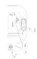
- the system 100is installed at a parking lot 105 , at which motor vehicles, such as cars, trucks, and motorcycles may be parked.
- a vehicle detection device 100detects arrival of vehicles and/or entry of vehicles and/or departure of vehicles to or from the parking lot 105 .
- a vehicle 101is adjacent a motor operated gate 125 selectively that permits vehicles to enter and depart from the parking lot 105 .
- a server 130is in communication with the vehicle detection device 110 over a network, such as the Internet, and receives data from the vehicle detection device 110 . The server 130 processes this data 130 , and may then send output to, or prompt for input from, a device of an operator of the parking lot 135 , or a device 102 within the vehicle 101 .
- Optional sensors or indicators 140are installed adjacent parking spots 106 .
- the device 102 within the vehicle 101may be a mobile wireless communications device utilized by the driver or passenger of the vehicle 101 , such as a smartphone, smartwatch, or tablet, or may be a device integrated within the vehicle 101 , such as an infotainment system.
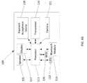
- the vehicle detection device 110includes a processor 111 , such as a microprocessor or system on a chip. Coupled to the processor 111 is a magnetometer 112 , as well as an accelerometer 113 . A Bluetooth module 115 is coupled to the processor 111 for potential communication with the device 102 within the vehicle 101 , and a transceiver 114 is coupled to the processor 111 for communication with the server 130 over the wide area network, and/or also with other vehicle detection devices 110 if present, and/or also with the optional sensors 140 . A display 117 , LED 123 , and speaker 125 are coupled to the processor 111 for providing visual or audio output to a user.
- a processor 111such as a microprocessor or system on a chip. Coupled to the processor 111 is a magnetometer 112 , as well as an accelerometer 113 .
- a Bluetooth module 115is coupled to the processor 111 for potential communication with the device 102 within the vehicle 101
- a transceiver 114is coupled to the processor
- a camera 121is coupled to the processor 111 for taking pictures, such as of the license plate of the vehicle 101 , which may be sent to and processed by the server.
- a payment acceptance device 119is coupled to the processor 111 for accepting payment from a user.
- the payment acceptance device 119may utilize magnetic strip, chip and pin, NFC, or other electronic payment acceptance technologies.
- the payment acceptance device 119may also directly accept hard currency, such as bills and coins.
- a RFID reader 126is coupled to the processor 111 for reading RFID tags associated with the vehicle, such as a toll tag mounted in the vehicle, or RFID tags within the tires of the vehicle.
- a payment acceptance device 119is coupled to the processor 111 for accepting payment from a user.
- the payment acceptance device 119may utilize magnetic strip, chip and pin, NFC, or other electronic payment acceptance technologies.
- the payment acceptance device 119may also directly accept hard currency, such as bills and coins. It should be appreciated that in some applications, the payment acceptance device 119 may be part of, or may be, the RFID reader 126 .
- the magnetometer 112serves to sense metal in vehicles 101 via a change in the local magnetic field, and can thus detect the presence of vehicles 101 .
- the processor 111may be able to interpret reading from the magnetometer 112 to estimate the dimensions of the vehicle 101 , from which a type or configuration of the vehicle may be inferred (i.e. a vehicle estimated to be a car, whereas a larger vehicle is likely to be a truck).
- the accelerometer 113serves to detect vibrations in multiple axes, such as those caused by a passing vehicle 101 , and can therefore be used to determine whether the vehicle 101 is entering or leaving the given area. By logging the magnitude and direction of vibrations detected by the accelerometer 113 , the processor 111 can infer both the speed of the vehicle, as well as whether the vehicle is arriving or departing.
- the vehicle detection device 110is positioned at the entrance and exit to the parking lot 105 , and needs not be driven over by the vehicle 101 in order for detection to occur.
- the RFID reader 126may read RFID tags associated with the vehicle.
- the RFID reader 126may read a code from the RFID tag, and the code may be a toll tag ID number, or may be a tire identification code.
- the information about the vehiclemay be the toll tag ID, which may in turn be used for identification of the user by looking up the user's information in a table of toll tag ID's, or in processing payment via the toll tag ID.
- the information about the vehiclemay be the tire identification code, which may in turn be used by the server to determine a make and model of the tires on the vehicle, which may in turn be used to determine the type of vehicle and vehicle configuration, as well as the make and model of the vehicle.
- the information about the vehiclemay include the various measurements taken by the accelerometer 113 and magnetometer 112 as well as the make and model of the tires, which may be used to more accurately determine the type of vehicle and vehicle configuration, as well as the make and model of the vehicle.
- the vehicle detection device 110may communicate with other vehicle detection devices 110 .
- one vehicle detection device 110may act as a relay for another vehicle detection device 110 , transmitting information received therefrom to the server 130 , or to the device 102 within the vehicle 101 .
- the transceiver 114may also be used by the vehicle detection device 110 for communication with a fixed or mobile device used by a parking lot attendant, such as a smartphone, tablet, or pay station.
- the processor 111may also cooperate with additional vehicle detection hardware, such as a pressure sensor for vehicle sensing, allowing retrofitting of the vehicle detection device 110 to existing parking lot management installations.
- vehicle detection hardwaresuch as a pressure sensor for vehicle sensing
- the processor 111may also cooperate with hardware, such as RFID readers, that read toll tags or toll passes, and/or Bluetooth connections from which vehicle information may be read, and via which payment for parking may be effectuated.
- each vehicle detection device 110may have the components as described above and below, and may operate as described above and below.
- the various vehicle detection devices 110may communicate with one another via their transceivers 114 , their Bluetooth modules 115 , or a combination thereof. This communication may be to relay data to and from the server 130 , for example.
- the various vehicle detection devices 110may cooperate using their Bluetooth modules 115 to perform triangulation to determine the position of the vehicle 101 within the parking lot 105 , and may then direct the driver of the vehicle 101 to the parking space 106 via the device 102 within the vehicle 101 , or via their respective displays 117 , LEDs 123 , and/or speakers 125 .
- each vehicle detection device 110communicates with a hub 109 either wirelessly or over a wire, and the hub 109 in turn communicates with the server 130 , serving to pass data to the server 130 from the vehicle detection devices 110 , and serving to pass data to the vehicle detection devices 110 from the server 130 .
- the hub 109may perform any of the functions described above or below as being performed by the vehicle detection device 110 .
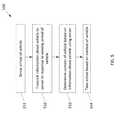
- the vehicle detection device 110operates to sense arrival (or departure) of a vehicle 101 (Block 551 ).
- the vehicle detection device 110then sense information about the vehicle 101 , and sends it to the server 130 in response to the sensing of arrival or departure (Block 552 ).
- the information about the vehiclemay be sensed via the magnetometer 112 and accelerometer 113 , and/or may be sensed via interaction with the device 102 within the vehicle 101 via the Bluetooth module 115 , or via the transceiver 114 .
- the server 130determines a context of the vehicle 101 based on the information received from the vehicle detection device 110 (Block 553 ). Thereafter, the server 130 takes at least one action based on the context of the vehicle 101 (Block 554 ).
- the system 100may be used in a wide variety of applications.
- the application shown in FIG. 1Ais that where the system 100 is installed at a parking lot 105 .
- a first parking related applicationis where a driver of the vehicle 101 has prepaid for parking via the device 102 .
- the vehicle detection device 110operates to read the prepayment (or voucher) information from the device 102 , or serves to identify the vehicle 101 via the device 102 and then query the server 130 for the prepayment or voucher information. If the prepayment or voucher is valid (i.e. has been properly paid for the correct amount, and/or if it is an authorized time of day, date, or day of the week), the vehicle detection device 110 or server 130 instructs the gate 125 to open, and updated parking lot inventory information is sent to the parking lot operator's device 135 .
- the vehicle detection device 110may, either on its own via its display 117 , LED 123 , and speaker 125 , or via the device 102 in the vehicle 101 , demand payment for the right to park the vehicle 101 in the parking lot 105 . If, within a given amount of time, the payment is not received (from either the device 102 , or in pieces from multiple devices 102 , or via the payment acceptance device 119 ) and the vehicle 101 has not left the parking lot, the vehicle detection device 110 , either on its own or via the server 130 , may notify the parking lot operator's device 135 that the vehicle 101 is parked in the parking lot 105 without having paid for the right to do so.
- the vehicle detection device 110serves to detect the number of devices 102 in the vehicle 101 , and transmits that information to the server. Since the majority of adults carry a smartphone in today's world, from this number of devices 102 in the vehicle 101 , the server 130 can estimate the number of people in the vehicle 101 , and may transmit this data to the parking lot operator's device 135 , may save this data for future analytics, or may transmit this data to other devices, such as those within a venue adjacent the parking lot 105 .
- the vehicle detection device 110serves to read user identity information from the device 102 in the vehicle, or to request user identity information associated with the device 102 from the server 130 . Then, the server 130 can notify the parking lot operator or venue that the user matching the user identity information has arrived. Therefore, the parking lot operator or venue can prepare for the arrival of that specific user.
- the specific usermay have reserved a given parking space 106 , and the parking lot operator may manually (via a human attendant) direct the vehicle 101 to park in the parking space 106 , or the server 130 may direct the vehicle 101 to park in the parking space 106 via displays incorporated with the sensors 140 , or via the display 117 , LED 123 , and/or speaker 125 .
- the sensors 140may report to the parking lot operator, the vehicle detection device 110 , or the server 130 which spaces are occupied. This functionality may also be performed by the vehicle detection device 110 . If the vehicle detection device 110 , via the sensors 140 or on its own, determines that the reserved space 106 has been improperly occupied (i.e. the space 106 is occupied, but the vehicle detection device 110 has not detected the device 102 of the specific user), the vehicle detection device 110 may directly or via the server 130 notify the parking lot operator's device 135 that the parking space 106 is occupied by an unauthorized vehicle.
- the vehicle detection device 110may determine both an arrival time and a departure time of the vehicle 101 , and the payment amount may be based upon the length of time between the arrival time and departure time.
- the payment amountmay be additional or alternatively be based upon the time of day, date, or day of week of the arrival time and/or departure time—for example the payment may be greater on a Saturday than on a Tuesday, or may be less at 2:00 AM than at 9:00 AM.
- the payment amountmay be dependent upon the weight, type, or configuration of the vehicle 101 (e.g. vehicle size, vehicle weight, vehicle body style, etc), as determined based on readings from the magnetometer 112 and/or accelerometer 113 .
- the vehicle 101may be authorized to park in the parking lot 105 at the time of parking, but may at a later point in time, before departure, become no longer authorized.
- the parking lot 105may be operated by a municipality, and may need to be emptied for street cleaning, trash pickup, etc.
- the server 130may notify the parking lot operator's device 135 (and thus the municipality's device) that certain vehicles have not yet departed. The municipality can then take appropriate action. In some cases, such notification may additional or alternatively be sent to the device 102 .
- Another parking applicationmay be where the parking lot 105 is a valet parking lot.
- the vehicle detection device 110may this record a unique identifier for the vehicle when it entered the parking lot 105 , and thus unique identifier may be transmitted, via the server 130 or directly, to the device 102 .
- a usermay request retrieval of the vehicle 101 via provided input to the device 102 .
- the parking lot 205is a parking lot for a merchant, such as a restaurant, and 205 may be a drive through lane instead of a parking lot.
- the vehicle detection device 210can detect when the vehicle 201 arrives at the merchant, and can read the identify of a user from the device 202 , or request an identity of the user from the server 230 based on information received from the device 202 .
- the server 230may then send the identity of the user to the merchant's device 235 , which may retrieve order information for the user.
- the server 230may have the order information for the user, and may pass the order information along to the merchant's device 235 .
- the vehicle detection device 210may cause the device 202 to prompt the user to enter an order.
- the user's ordermay then be transmitted to a device inside the Merchant's business wherein it is prepared and delivered to the user.
- the system 200may compute the time required to prepare the user's order and, comparing such time to the time required to prepare other users' orders within the drive through lane, may direct the Merchant's employees to prepare orders in a sequence different from the sequence of vehicles in the drive through queue in an effort to minimize user wait times and maximize efficiency.
- the parking lot 305is for trucks 301 at a shipping yard.
- the vehicle detection system 310may retrieve a shipping manifest from the device 302 , server 330 , or shipping yard's device 335 , and pass the shipping manifest along to any such device.
- the server 330 or shipping yard's device 335knowing that the shipment having that shipping manifest has arrived, may notify the owner of the cargo.
- the server 330may, either directly or via the vehicle detection system 310 , notify the device 302 or the sensors 306 to direct the driver where to park the truck.
- Additional sensors 303may be placed in the cargo containers carried by the trucks 301 , and these sensors may detect when the cargo container is being moved (for example, from a 301 to storage), and transmit that data to the server 330 via the vehicle detection device 310 . The server 330 may then report that data to the shipping yard's device 335 .
- a method of operating the vehicle sensing device 110includes detecting entry of the vehicle to the given area via the vehicle detector (e.g. magnetometer 112 , accelerometer 113 , etc) at Block 651 . Thereafter, the method includes determining information about the vehicle, in response to sensing arrival of the vehicle to the given location, using the wireless transceiver 114 and/or the vehicle detector (e.g. magnetometer 112 , accelerometer 113 , etc) at Block 652 . Then, the method continued with transmitting information to the server using the transceiver 114 at Block 653 .
- the vehicle detectore.g. magnetometer 112 , accelerometer 113 , etc
- the processor 111may transmit an application trigger to cause the device within the vehicle (e.g. smartphone, infotainment system, etc) to launch an application.
- This applicationmay prompt the user for payment, provide the user with notice that they are authorized or not authorized, provide the user with information about where to park, where to pick up cargo, or where to drop off cargo, provide the user with information about valet parking (such as price), or provide the user with information about an order from a merchant.
- a hub 109works in accordance with a counting device 141 to perform the above functions.
- the hub 109contains similar components to the vehicle sensing device described above, as is apparent from FIG. 4B , and has similar functionality to the vehicle sensing device as well, with the exception being that it lacks a magnetometer and accelerometer, and instead determines arrival and departure of vehicles via triggering of the counting device 141 by the weight of the vehicles driving over the counting device 141 .
- the hub 109may actually be a portable wireless electronic device, such as a smartphone or tablet.
- the parking system 50includes one or more parking sensor apparatuses 52 situated at the entrance or exit lanes to a parking lot.
- Each parking sensor apparatus 52includes, for example, four three-axis magnetometers 54 a - 54 d positioned in a rectangular shape.
- the magnetometers 54 a - 54 dare coupled to processing circuitry 53 , such as an application specific integrated circuit.
- the processing circuitry 53is coupled to a transmitter 55 , which wirelessly communicates with modem 49 . In some applications, such as that shown in FIG.
- the processing circuitry 53converts signals received from the magnetometers 54 a - 54 d into a format usable by cellular modem 49 for transmission to a cloud based server 60 .
- the processing circuitry 53processes the signals received from the magnetometers 54 a - 54 d to determine the properties of vehicles driving over the parking sensor apparatus 52 (such as speed, direction, length, etc) and sends those determined values to the cloud based server 60 .
- Which configuration is used for a given installationmay depend on the particular details of that installation. For example, if the parking sensor apparatus 52 and cellular modem 49 is to be powered by a battery, using the processing circuitry 53 to determine the properties of the vehicles so as to reduce the amount of data sent by the cellular modem 49 may help provide for greater battery life over sending the signals from the magnetometers 54 a - 54 d to the cloud based server 60 . On the other hand, where battery life is not a concern, it may be desirable for the cloud based server 60 to determine the properties of the vehicles so as to allow for easy updating of the analysis techniques used, as well as for additional data processing power.
- the magnetometers 54 a - 54 dmay each have analog to digital conversion circuitry associated therewith (not shown), or packaged therewith (not shown), that sends data to the processing circuitry 53 directly or over a bus connection.
- modem 49has been described as a cellular modem, it may in some cases instead be a wireless network transceiver (e.g. WiFi), or may be a wired network interface (e.g. Ethernet).
- WiFiwireless network transceiver
- Ethernetwired network interface
- a vehicledrives over the parking apparatus 52 , and each magnetometer 54 a - 54 d of the parking apparatus 52 repeatedly produces a waveform corresponding to magnetic features, or a magnetic signature, of the vehicle, at a rate of, for example, 50 times per second to 800 times per second.
- the Inventorhas found that the specific waveforms produced for different vehicles are influenced by unpredictable factors, making extraction of information directly from the waveforms to be difficult. However, the Inventor has also found that the specific waveforms produced by a given vehicle are consistent across the magnetometers 54 a - 54 d . Therefore, by comparing the waveforms produced by the magnetometers 54 a - 54 d to one another while varying an applied time offset, in response to a car driving over the parking apparatus 52 , the direction and speed of the vehicle may be determined.
- the server 60may perform the above mentioned comparisons ( FIG. 7A ), or the processing circuitry 53 may perform the above mentioned comparisons ( FIG. 7B ). Since each magnetometer 54 a - 54 d produces numerous magnetic signatures of the vehicle as it drives over, each waveform from each magnetometer 54 a - 54 d is compared to each waveform from each other magnetometer 54 a - 54 d while a variable time offset therebetween is adjusted so as to locate a match. Examples of such comparisons are shown in FIGS. 10-11 , with FIG. 10 showing magnetic signatures for a Toyota 4Runner SUV, and FIG. 11 showing magnetic signatures for a Ford F-150.
- the direction of the vehicleis in a direction from magnetometer 54 a to magnetometer 54 b.
- the server 60can accurately maintain a count of the number of vehicles in the parking lot, even when a vehicle enters through a designated exit, exits through a designated entrance, or enters or exits through an undefined area serving as both entry and exit. Where the direction of the vehicle indicates that the vehicle is leaving the parking lot, the count of the number of vehicles in the parking lot is decremented by the server 60 ; likewise, where the direction of the vehicle indicates that the vehicle is entering the parking lot, the count of the number of the vehicles in the parking lot is incremented by the server 60 .
- a parking lotcan utilize undesignated entrances and exits, permitting for quicker traffic flow in some scenarios (i.e. all act as entrances at a stadium prior to a sporting event, and all act as exits at the stadium after the sporting event) while still allowing for automated monitoring of parking inventors.
- the parking lotmay have a combination of defined and undefined entrances and exists.
- FIG. 9Such a configuration is shown in FIG. 9 , where the parking lot 40 includes sensor apparatuses 52 o and 52 p located at defined single lane entrances or exits, and with sensor apparatuses 52 a - 52 n located at a wide open undefined area through which vehicles may enter and exit.
- the server 60 or processing circuitry 53may determine the speed of the vehicle. For example, speed can be calculated as distance/time, the distance between the various magnetometers 54 a - 54 d is known. Therefore, as an example, the speed may be calculated as the distance between the magnetometers (from among 54 a - 54 d ) that generated a pair of similar yet time delayed with respect to one another waveforms, divided by the time delay between peak values of those waveforms.
- points of peak similaritysuch as peak values, zero crossings, or other readily identifiable features for delay comparisons allows for a more precise match between the waveforms than simply using a beginning or end of the waveform for the delay comparisons.
- a graph showing points of peak similarity between magnetic signatures and the delay between those points of peak similarityis shown in FIG. 12 , where the X axis corresponds to time-delays where peak similarities have occurred between compared magnetic signatures, and where the Y axis corresponds to the degree of that similarity.
- the determined speed of the vehiclemay be used in further calculations.
- the server 60 or processing circuitry 53may estimate a length of the vehicle as a product of the determined speed and a duration of the waveform. From the estimated length, the server 60 may then estimate whether the vehicle is a car, truck, SUV, or commercial vehicle by comparing the length to a series of threshold sizes.
- the server 60may determine the vehicle to be a commercial vehicle if the length is greater than an upper threshold, may determine the vehicle to be a truck or SUV if the vehicle's length is greater than or equal to a middle threshold and less than the upper threshold, and may determine the vehicle to be a car if the vehicle's length is greater than or equal to a lower threshold and less than the middle threshold length.
- the server 60may use upper and lower threshold lengths, with the vehicle length being greater than the upper threshold meaning that the vehicle is a commercial vehicle, and the vehicle length being greater than or equal to a lower threshold and less than the upper threshold meaning that the vehicle is a private vehicle. Indeed, it should be appreciated that any suitable thresholds, number of thresholds, and comparison operators may be used.
- this functionalitycan be used to reject a waveform as representing a false positive, such as where the vehicle length is less than the lower threshold. This may mean that a pedestrian carrying a metallic object, or riding a metallic object such as a wheelchair, mobility cart, or bicycle has passed over the sensor apparatus 52 , and thus should not be counted in the determination of parking lot space inventory.
- the parking apparatus 52 as shownincludes four magnetometers 54 a - 54 d arranged into a rectangular shape, other numbers of magnetometers and other shapes may be used. Indeed, there may be two, three, five, six, or any suitable number of magnetometers arranged into any usable shape.
- three magnetometersmay be arranged into a triangular shape. This arrangement may be suitable for entrances and exits to parking lots without physical barriers restricting the movement of vehicles, such that vehicles may drive over the magnetometers from multiple different directions.
- the same part of vehicles entering or exiting the parking lotmay not drive over two of the magnetometers, which can lead to a greater amount of inaccuracy in the determination of speed and direction of the vehicle.
- the parking lot in which the system 50 is locatedmay be small enough such that a single modem is in communication distance with each sensor apparatus, such as that shown in FIG. 8 where modem 49 d is in communication with sensor apparatuses 52 h - 52 j.
- the parking lot in which the system 50 is locatedmay be too large, or may be multi-level, for direct communication between each sensor apparatus and the modem to be feasable.
- repeatersmay be used.
- sensor apparatuses 52 f - 52 g on a first floor or in a first areamay communicate with repeater 49 c , which in turn communicates with repeater 49 b on a second floor or in a second area, which in turn communicates with modem 49 a on a third floor or in a third area.
- repeater 49 bcommunicates with sensor apparatuses 52 d - 52 e
- modem 49 acommunicates with sensor apparatuses 52 a - 52 c.
- the server 60 or processing circuitry 53may instead compare the waveforms from the magnetometer 54 to a knowledge base of known waveforms for known vehicles.
- Each known vehiclemay have multiple known waveforms associated with it and stored in the knowledge base. These multiple known waveforms for each known vehicle may each be a waveform of the vehicle driving over the sensor apparatus 52 from a different direction or angle. These known waveforms may each be directly measured using a sensor apparatus identical to, or similar to, that of the sensor apparatus 52 ; alternatively, some known waveforms may be directly measured, while others may be extrapolated from those that were directly measured.
- the server 60 or processing circuitry 53can then retrieve information about the known vehicle associated with that waveform, such as the make and model, vehicle orientation, direction of travel, and position of vehicle relative to the sensor apparatus 52 .
- the known vehicle associated with that waveformsuch as the make and model, vehicle orientation, direction of travel, and position of vehicle relative to the sensor apparatus 52 .
- waveforms from magnetometer 54may match those of a Ford F-150 driving across the sensor apparatus 52 at a 45 degree angle from the lower left corner of the sensor apparatus 52 to the upper right corner of the sensor apparatus 52 .
- waveforms from magnetometer 54may match those of a Toyota 4Runner driving across the sensor apparatus 52 from the right to the left, with the sensor apparatus substantially centered along a longitudinal axis of the vehicle, in a reverse direction.
- the server 60 or processing circuitry 53may use a learned machine technique to identify the make, model, vehicle orientation, direction of travel, and position of the vehicle relative to the sensor apparatus 52 .
- This learned machine technique, utilized by the server 60 or magnetometermay be produced using a machine learning technique (such as using an artificial neural network) performed on the aforementioned knowledgebase or similar, and may be continually updated.
- the speed of the vehiclemay be estimated from the length of the known identified vehicle multiplied by the duration of the measured waveforms from the magnetometer 54 .
- accelerometersmay be used in conjunction with magnetometers.
- the accelerometersmay be positioned adjacent to the magnetometers, and vibration signatures may be collected together with the magnetic signatures.
- the vibration signaturesmay be compared and analyzed like the magnetometers as described above, and the results thereof may be fused or combined with the results of comparing and analyzing the magnetic signatures to produce more accurate results.
- accelerometersmay be used instead of magnetometers, and vibration signatures may be collected, compared, and analyzed like the magnetometers as described above.
Landscapes
- Physics & Mathematics (AREA)
- General Physics & Mathematics (AREA)
- Chemical & Material Sciences (AREA)
- Analytical Chemistry (AREA)
- Traffic Control Systems (AREA)
- Devices For Checking Fares Or Tickets At Control Points (AREA)
Abstract
Description
Claims (18)
Priority Applications (3)
| Application Number | Priority Date | Filing Date | Title |
|---|---|---|---|
| US15/711,897US10446024B2 (en) | 2017-09-21 | 2017-09-21 | Parking sensors capable of determining direction and speed of vehicle entering or leaving a parking lot |
| PCT/US2018/052005WO2019060580A1 (en) | 2017-09-21 | 2018-09-20 | Parking sensors capable of determining direction and speed of vehicle entering or leaving a parking lot |
| US16/601,277US10943475B2 (en) | 2017-09-21 | 2019-10-14 | Parking sensors capable of determining direction and speed of vehicle entering or leaving a parking lot |
Applications Claiming Priority (1)
| Application Number | Priority Date | Filing Date | Title |
|---|---|---|---|
| US15/711,897US10446024B2 (en) | 2017-09-21 | 2017-09-21 | Parking sensors capable of determining direction and speed of vehicle entering or leaving a parking lot |
Related Child Applications (1)
| Application Number | Title | Priority Date | Filing Date |
|---|---|---|---|
| US16/601,277ContinuationUS10943475B2 (en) | 2017-09-21 | 2019-10-14 | Parking sensors capable of determining direction and speed of vehicle entering or leaving a parking lot |
Publications (2)
| Publication Number | Publication Date |
|---|---|
| US20190088119A1 US20190088119A1 (en) | 2019-03-21 |
| US10446024B2true US10446024B2 (en) | 2019-10-15 |
Family
ID=65720450
Family Applications (2)
| Application Number | Title | Priority Date | Filing Date |
|---|---|---|---|
| US15/711,897Active2037-10-05US10446024B2 (en) | 2017-09-21 | 2017-09-21 | Parking sensors capable of determining direction and speed of vehicle entering or leaving a parking lot |
| US16/601,277ActiveUS10943475B2 (en) | 2017-09-21 | 2019-10-14 | Parking sensors capable of determining direction and speed of vehicle entering or leaving a parking lot |
Family Applications After (1)
| Application Number | Title | Priority Date | Filing Date |
|---|---|---|---|
| US16/601,277ActiveUS10943475B2 (en) | 2017-09-21 | 2019-10-14 | Parking sensors capable of determining direction and speed of vehicle entering or leaving a parking lot |
Country Status (2)
| Country | Link |
|---|---|
| US (2) | US10446024B2 (en) |
| WO (1) | WO2019060580A1 (en) |
Cited By (4)
| Publication number | Priority date | Publication date | Assignee | Title |
|---|---|---|---|---|
| CN110310490A (en)* | 2019-04-23 | 2019-10-08 | 深圳市戴升智能科技有限公司 | Vehicle speed estimation method, apparatus, computer equipment and storage medium |
| US10943475B2 (en)* | 2017-09-21 | 2021-03-09 | The Parking Genius, Inc. | Parking sensors capable of determining direction and speed of vehicle entering or leaving a parking lot |
| US11386780B2 (en) | 2016-01-13 | 2022-07-12 | Parkhub, Inc. | System for monitoring arrival of a vehicle at a given location and associated methods |
| US11455838B2 (en) | 2016-01-13 | 2022-09-27 | Parkhub, Inc. | System for monitoring arrival of a vehicle at a given location and associated methods |
Families Citing this family (10)
| Publication number | Priority date | Publication date | Assignee | Title |
|---|---|---|---|---|
| DE102015217923A1 (en)* | 2015-09-18 | 2017-03-23 | Robert Bosch Gmbh | Securing a motor vehicle |
| US10803423B2 (en) | 2016-09-29 | 2020-10-13 | The Parking Genius, Inc. | System for managing parking of autonomous driving vehicles |
| US10299122B2 (en) | 2016-11-23 | 2019-05-21 | The Parking Genius, Inc. | User validation system utilizing symbolic or pictographic representations of validation codes |
| US10325497B2 (en) | 2017-09-21 | 2019-06-18 | The Parking Genius, Inc. | Parking sensors capable of determining direction and speed of vehicle entering or leaving a parking lot using magnetic signature recognition |
| US11214933B2 (en)* | 2018-03-30 | 2022-01-04 | Total Automation Group, Inc. | Systems and methods for monitoring access to a secured area |
| JP2022149983A (en)* | 2021-03-25 | 2022-10-07 | トヨタ自動車株式会社 | Information processing device, method, and program |
| GB2606397B (en)* | 2021-05-07 | 2023-07-19 | Three Smith Group Ltd | Damage detection system |
| US11595226B1 (en)* | 2021-08-17 | 2023-02-28 | Xerox Corporation | Method and system for collecting sensor data in buildings |
| US12114386B2 (en) | 2021-08-17 | 2024-10-08 | Xerox Corporation | Building environmental sensor method and system for collecting data from same |
| US11856419B2 (en) | 2021-08-17 | 2023-12-26 | Xerox Corporation | Method and system for commissioning environmental sensors |
Citations (66)
| Publication number | Priority date | Publication date | Assignee | Title |
|---|---|---|---|---|
| US4239415A (en)* | 1978-11-06 | 1980-12-16 | Blikken Wendell A | Method of installing magnetic sensor loops in a multiple lane highway |
| US5331276A (en)* | 1992-09-16 | 1994-07-19 | Westinghouse Electric Corporation | Apparatus for passively measuring the velocity of a ferrous vehicle along a path of travel |
| US5491475A (en)* | 1993-03-19 | 1996-02-13 | Honeywell Inc. | Magnetometer vehicle detector |
| US5648904A (en)* | 1994-04-25 | 1997-07-15 | Sony Corporation | Vehicle traffic system and method |
| US5880682A (en)* | 1997-12-18 | 1999-03-09 | Midian Electronics, Inc. | Traffic control system and method of operation |
| US20020190856A1 (en) | 2001-06-04 | 2002-12-19 | Vehiclesense, Inc. | Wireless vehicle detection systems |
| US6675123B1 (en)* | 2002-11-26 | 2004-01-06 | The United States Of America As Represented By The Secretary Of The Army | Magnetic tracking methods and systems |
| US20040012481A1 (en) | 2000-05-26 | 2004-01-22 | Thierry Brusseaux | Closed parking lot for motor vehicles, equipment items therefor and management method |
| US20040222903A1 (en) | 2003-05-08 | 2004-11-11 | Shih-Hsiung Li | Management method and system for a parking lot |
| US6865455B1 (en)* | 2003-02-19 | 2005-03-08 | The United States Of America As Represented By The Secretary Of The Navy | Magnetic anomaly guidance system and method |
| US20050280555A1 (en) | 2004-06-22 | 2005-12-22 | Warner Frederick M Iv | Mathods & apparatus dynamically managing parking |
| US20070015485A1 (en) | 2005-07-14 | 2007-01-18 | Scosche Industries, Inc. | Wireless Media Source for Communication with Devices on Data Bus of Vehicle |
| US20070050240A1 (en) | 2005-08-30 | 2007-03-01 | Sensact Applications, Inc. | Wireless Parking Guidance System |
| US20070162218A1 (en)* | 2006-01-11 | 2007-07-12 | Commissariat A L'energie Atomique | Magnetic traffic control system |
| US20070245158A1 (en) | 2005-11-30 | 2007-10-18 | Giobbi John J | Single step transaction authentication using proximity and biometric input |
| US20110057815A1 (en) | 2009-09-04 | 2011-03-10 | Ips Group, Inc. | Parking meter communications for remote payment with updated display |
| US20110137773A1 (en) | 2009-12-08 | 2011-06-09 | At&T Mobility Ii Llc | Devices, Systems and Methods for Identifying and/or Billing an Individual in a Vehicle |
| US20110172909A1 (en) | 2010-01-08 | 2011-07-14 | Philippe Kahn | Method and Apparatus for an Integrated Personal Navigation System |
| US20110213672A1 (en) | 2009-10-19 | 2011-09-01 | Liberty Pluglns, Inc. | System and method for managing a parking lot |
| US8056667B2 (en) | 2008-04-22 | 2011-11-15 | GM Global Technology Operations LLC | Autonomous parking strategy based on available parking space |
| US8099214B2 (en) | 2009-02-09 | 2012-01-17 | GM Global Technology Operations LLC | Path planning for autonomous parking |
| US20120056758A1 (en) | 2009-12-03 | 2012-03-08 | Delphi Technologies, Inc. | Vehicle parking spot locator system and method using connected vehicles |
| US20120092190A1 (en) | 2010-10-14 | 2012-04-19 | Xerox Corporation | Computer-Implemented System And Method For Managing Motor Vehicle Parking Reservatons |
| US20120182160A1 (en) | 2011-01-14 | 2012-07-19 | TCS International, Inc. | Directional Vehicle Sensor Matrix |
| US20120246079A1 (en) | 2011-03-24 | 2012-09-27 | Dave William Wilson | Authentication using application authentication element |
| US20120285790A1 (en) | 2011-05-10 | 2012-11-15 | Duncan Solutions, Inc. | Wireless communication parking meter system and method |
| US20130103200A1 (en) | 2011-10-20 | 2013-04-25 | Apple Inc. | Method for locating a vehicle |
| US20130135118A1 (en) | 2011-11-16 | 2013-05-30 | Flextronics Ap, Llc | Parking meter expired alert |
| US20130147954A1 (en) | 2011-12-13 | 2013-06-13 | Electronics And Telecommunications Research Institute | Parking lot management system in working cooperation with intelligent cameras |
| US20140036076A1 (en) | 2012-08-06 | 2014-02-06 | Steven David Nerayoff | Method for Controlling Vehicle Use of Parking Spaces by Use of Cameras |
| US20140046506A1 (en) | 2012-08-11 | 2014-02-13 | Audi Ag | Method of autonomous movement of a vehicle in a parking area |
| US20140218218A1 (en) | 2013-01-28 | 2014-08-07 | Commercial Finance Corporation, Sa De Panama | Systems, methods, and devices for securing cargo |
| US20140232563A1 (en)* | 2011-09-27 | 2014-08-21 | Intelligent Imaging Systems Inc. | Vehicle identification |
| US20140232518A1 (en) | 2013-02-15 | 2014-08-21 | Cah Technology | Systems and methods for an automated parking facility |
| US20140249742A1 (en) | 2013-03-01 | 2014-09-04 | Palo Alto Research Center Incorporated | Computer-Implemented System And Method For Spontaneously Identifying And Directing Users To Available Parking Spaces |
| US20140350853A1 (en) | 2013-05-21 | 2014-11-27 | Xerox Corporation | Route computation for navigation system using data exchanged with ticket vending machines |
| US20140368327A1 (en) | 2013-06-13 | 2014-12-18 | Infineon Technologies Ag | RFID-tag, a TPMS Device, a Tire, a Receiver Device and a Method for Providing Information related to Identification of a Tire |
| US20150016661A1 (en) | 2013-05-03 | 2015-01-15 | Digimarc Corporation | Watermarking and signal recognition for managing and sharing captured content, metadata discovery and related arrangements |
| US20150066607A1 (en) | 2009-12-11 | 2015-03-05 | Societe Stationnement Urbain Developpements Et Etudes (Sude Sas) | City parking services with area based loyalty programs |
| US8977652B2 (en) | 2009-09-17 | 2015-03-10 | Oracle International Corporation | Client-side API framework for uniform resource identifier (URI) manipulations |
| US20150117704A1 (en) | 2012-09-13 | 2015-04-30 | Xerox Corporation | Bus lane infraction detection method and system |
| US20150138001A1 (en) | 2013-11-18 | 2015-05-21 | ImageMaker Development Inc. | Automated parking space management system with dynamically updatable display device |
| US20150149265A1 (en) | 2013-11-27 | 2015-05-28 | GM Global Technology Operations LLC | Controlled parking of autonomous vehicles |
| US20150179070A1 (en) | 2013-12-20 | 2015-06-25 | Frogparking Limited | Location-Based Vehicle Parking System |
| US20150241241A1 (en) | 2014-02-27 | 2015-08-27 | International Business Machines Corporation | Identifying cost-effective parking for an autonomous vehicle |
| US20150279210A1 (en) | 2014-03-26 | 2015-10-01 | Alexandra C. Zafiroglu | Orchestrating autonomous movements of parked vehicles to optimize parking efficiency |
| WO2015144396A1 (en) | 2014-03-26 | 2015-10-01 | Here Global B.V. | Method and apparatus for identifying parking spaces for a group of vehicles |
| US20150294210A1 (en) | 2014-04-10 | 2015-10-15 | Neology, Inc. | Universal transponder |
| US20150317840A1 (en) | 2012-04-23 | 2015-11-05 | Transparent Wireless Systems, Llc | Methods and systems for electronic payment for on-street parking |
| US20150334678A1 (en) | 2014-05-16 | 2015-11-19 | Apple Inc. | Batch processing for improved georeferencing |
| US20150346727A1 (en) | 2015-08-12 | 2015-12-03 | Madhusoodhan Ramanujam | Parking Autonomous Vehicles |
| US20150367234A1 (en) | 2014-06-19 | 2015-12-24 | Google Inc. | Notifications on game controller |
| US20160071415A1 (en) | 2014-09-04 | 2016-03-10 | Denso Corporation | Parking space recognition apparatus and parking space recognition system |
| US20160104328A1 (en) | 2014-10-08 | 2016-04-14 | Innova Electronics, Inc. | System for detecting the operational status of a vehicle using a handheld communication device |
| US20160125736A1 (en) | 2014-10-31 | 2016-05-05 | Toyota Motor Engineering & Manufacturing North America, Inc. | Method to improve parking space identification in autonomous driving |
| US20160189435A1 (en) | 2014-12-29 | 2016-06-30 | Here Global B.V. | Optimized Parking System |
| US20160219012A1 (en) | 2013-09-12 | 2016-07-28 | Nokia Technologies Oy | Method and Apparatus for Token Determination for People Awareness and Location Sharing |
| US20160275794A1 (en) | 2015-03-16 | 2016-09-22 | Hon Hai Precision Industry Co., Ltd. | Detecting device, cloud server, and parking space managing system |
| US20170140645A1 (en)* | 2015-11-06 | 2017-05-18 | The Board Of Regents Of The University Of Oklahoma | Traffic monitoring system |
| US20170200365A1 (en)* | 2016-01-13 | 2017-07-13 | The Parking Genius, Inc dba ParkHub.com | System for monitoring arrival of a vehicle at a given location and associated methods |
| US20180089631A1 (en)* | 2016-09-29 | 2018-03-29 | The Parking Genius, Inc dba ParkHub.com | System for managing parking of autonomous driving vehicles |
| US20180114438A1 (en) | 2015-03-23 | 2018-04-26 | Philips Lighting Holding B.V. | Luminaire parking guidance |
| US20180247534A1 (en)* | 2017-02-24 | 2018-08-30 | Christopher Williams | Integrated system for monitoring parking lot conditions |
| US10135440B2 (en) | 2017-04-13 | 2018-11-20 | PNI Sensor | Magnetic field triggering |
| US20190088129A1 (en)* | 2017-09-21 | 2019-03-21 | The Parking Genius, Inc. dba ParkHub.com | Parking sensors capable of determining direction and speed of vehicle entering or leaving a parking lot using magnetic signature recognition |
| US20190088119A1 (en)* | 2017-09-21 | 2019-03-21 | The Parking Genius, Inc. dba ParkHub.com | Parking sensors capable of determining direction and speed of vehicle entering or leaving a parking lot |
Family Cites Families (29)
| Publication number | Priority date | Publication date | Assignee | Title |
|---|---|---|---|---|
| US3105221A (en)* | 1959-06-01 | 1963-09-24 | Peter D Schwarz | Traffic counting apparatus |
| US3541308A (en)* | 1968-03-28 | 1970-11-17 | Ibm | Automated parking facility |
| US4361202A (en)* | 1979-06-15 | 1982-11-30 | Michael Minovitch | Automated road transportation system |
| DE4427549C2 (en)* | 1994-08-04 | 1997-03-20 | Weiss Electronic Elektronische | Method and device for determining the speed of vehicles |
| WO2000008618A2 (en)* | 1998-08-07 | 2000-02-17 | 3461513 Canada Inc. | A vehicle presence detection system |
| JP3421768B2 (en) | 2000-03-30 | 2003-06-30 | 学校法人金沢工業大学 | Autonomous vehicle route guidance method, autonomous vehicle route guidance device, and autonomous vehicle equipped with route guidance device |
| US6864804B1 (en)* | 2001-10-17 | 2005-03-08 | Jim Allen | Ferromagnetic loop |
| TW200629188A (en) | 2005-02-04 | 2006-08-16 | Sin Etke Technology Co Ltd | Traffic control system using short-range beacons |
| TW200723149A (en)* | 2005-12-06 | 2007-06-16 | Sin Etke Technology Co Ltd | Parking lot reservation system with electronic identification |
| WO2008061099A2 (en)* | 2006-11-13 | 2008-05-22 | Noel Ii Phares A | Space monitoring detector |
| US7826409B2 (en) | 2006-12-26 | 2010-11-02 | Motorola, Inc. | Route identification using short range wireless beaconing devices |
| TWI402506B (en) | 2009-09-03 | 2013-07-21 | Ind Tech Res Inst | Method and system for motion tracking |
| US10002466B2 (en) | 2010-07-21 | 2018-06-19 | Verizon Patent And Licensing Inc. | Method and system for providing autonomous car errands |
| JP2012098841A (en)* | 2010-10-29 | 2012-05-24 | Jvc Kenwood Corp | Guidance device, method and program |
| WO2014147510A1 (en) | 2013-03-18 | 2014-09-25 | Koninklijke Philips N.V. | Methods and apparatus for information management and control of outdoor lighting networks |
| CA2952856A1 (en) | 2014-06-18 | 2015-12-23 | Sensity Systems Inc. | Application framework for interactive light sensor networks |
| DE102014221751A1 (en) | 2014-10-27 | 2016-04-28 | Robert Bosch Gmbh | Method and device for driving a vehicle in a parking lot |
| DE102014221777A1 (en) | 2014-10-27 | 2016-04-28 | Robert Bosch Gmbh | Method and device for operating a vehicle |
| CN112902975B (en) | 2015-02-10 | 2024-04-30 | 御眼视觉技术有限公司 | Autonomous vehicle navigation method, readable device, server, vehicle and system |
| DE102015202471B4 (en) | 2015-02-12 | 2018-01-18 | Robert Bosch Gmbh | Method and device for operating a parking space |
| KR101556947B1 (en) | 2015-03-31 | 2015-10-06 | 파킹클라우드 주식회사 | Parking lot management method, parking lot managing server and parking lot managing system |
| US9408041B1 (en) | 2015-04-24 | 2016-08-02 | Insensi, Inc. | Premise occupancy detection based on smartphone presence |
| CA2987052A1 (en)* | 2015-05-04 | 2016-11-10 | Pink Park Ltd. | Parking space management system and method |
| EP3091372A1 (en)* | 2015-05-05 | 2016-11-09 | Centro de Cálculo Igs Software S.L. | Vehicle detection system |
| KR101637842B1 (en) | 2015-07-08 | 2016-07-07 | 현대자동차주식회사 | Autonomous Driving System and Method in Parking Lot |
| CA2908762C (en)* | 2015-10-16 | 2024-01-02 | Imperial Parking Canada Corporation | Method and system for managing parking by dual location verification |
| US10607485B2 (en) | 2015-11-11 | 2020-03-31 | Sony Corporation | System and method for communicating a message to a vehicle |
| US9696721B1 (en)* | 2016-03-21 | 2017-07-04 | Ford Global Technologies, Llc | Inductive loop detection systems and methods |
| US10299122B2 (en)* | 2016-11-23 | 2019-05-21 | The Parking Genius, Inc. | User validation system utilizing symbolic or pictographic representations of validation codes |
- 2017
- 2017-09-21USUS15/711,897patent/US10446024B2/enactiveActive
- 2018
- 2018-09-20WOPCT/US2018/052005patent/WO2019060580A1/ennot_activeCeased
- 2019
- 2019-10-14USUS16/601,277patent/US10943475B2/enactiveActive
Patent Citations (69)
| Publication number | Priority date | Publication date | Assignee | Title |
|---|---|---|---|---|
| US4239415A (en)* | 1978-11-06 | 1980-12-16 | Blikken Wendell A | Method of installing magnetic sensor loops in a multiple lane highway |
| US5331276A (en)* | 1992-09-16 | 1994-07-19 | Westinghouse Electric Corporation | Apparatus for passively measuring the velocity of a ferrous vehicle along a path of travel |
| US5491475A (en)* | 1993-03-19 | 1996-02-13 | Honeywell Inc. | Magnetometer vehicle detector |
| US5648904A (en)* | 1994-04-25 | 1997-07-15 | Sony Corporation | Vehicle traffic system and method |
| US5880682A (en)* | 1997-12-18 | 1999-03-09 | Midian Electronics, Inc. | Traffic control system and method of operation |
| US20040012481A1 (en) | 2000-05-26 | 2004-01-22 | Thierry Brusseaux | Closed parking lot for motor vehicles, equipment items therefor and management method |
| US20020190856A1 (en) | 2001-06-04 | 2002-12-19 | Vehiclesense, Inc. | Wireless vehicle detection systems |
| US6675123B1 (en)* | 2002-11-26 | 2004-01-06 | The United States Of America As Represented By The Secretary Of The Army | Magnetic tracking methods and systems |
| US6865455B1 (en)* | 2003-02-19 | 2005-03-08 | The United States Of America As Represented By The Secretary Of The Navy | Magnetic anomaly guidance system and method |
| US20040222903A1 (en) | 2003-05-08 | 2004-11-11 | Shih-Hsiung Li | Management method and system for a parking lot |
| US20050280555A1 (en) | 2004-06-22 | 2005-12-22 | Warner Frederick M Iv | Mathods & apparatus dynamically managing parking |
| US20070015485A1 (en) | 2005-07-14 | 2007-01-18 | Scosche Industries, Inc. | Wireless Media Source for Communication with Devices on Data Bus of Vehicle |
| US20070050240A1 (en) | 2005-08-30 | 2007-03-01 | Sensact Applications, Inc. | Wireless Parking Guidance System |
| US20110099126A1 (en) | 2005-08-30 | 2011-04-28 | Sensact Applications, Inc. | Automated Parking Policy Enforcement System |
| US20070245158A1 (en) | 2005-11-30 | 2007-10-18 | Giobbi John J | Single step transaction authentication using proximity and biometric input |
| US20070162218A1 (en)* | 2006-01-11 | 2007-07-12 | Commissariat A L'energie Atomique | Magnetic traffic control system |
| US8056667B2 (en) | 2008-04-22 | 2011-11-15 | GM Global Technology Operations LLC | Autonomous parking strategy based on available parking space |
| US8099214B2 (en) | 2009-02-09 | 2012-01-17 | GM Global Technology Operations LLC | Path planning for autonomous parking |
| US20110057815A1 (en) | 2009-09-04 | 2011-03-10 | Ips Group, Inc. | Parking meter communications for remote payment with updated display |
| US8977652B2 (en) | 2009-09-17 | 2015-03-10 | Oracle International Corporation | Client-side API framework for uniform resource identifier (URI) manipulations |
| US20110213672A1 (en) | 2009-10-19 | 2011-09-01 | Liberty Pluglns, Inc. | System and method for managing a parking lot |
| US20120056758A1 (en) | 2009-12-03 | 2012-03-08 | Delphi Technologies, Inc. | Vehicle parking spot locator system and method using connected vehicles |
| US20110137773A1 (en) | 2009-12-08 | 2011-06-09 | At&T Mobility Ii Llc | Devices, Systems and Methods for Identifying and/or Billing an Individual in a Vehicle |
| US20150066607A1 (en) | 2009-12-11 | 2015-03-05 | Societe Stationnement Urbain Developpements Et Etudes (Sude Sas) | City parking services with area based loyalty programs |
| US20110172909A1 (en) | 2010-01-08 | 2011-07-14 | Philippe Kahn | Method and Apparatus for an Integrated Personal Navigation System |
| US20120095791A1 (en) | 2010-10-14 | 2012-04-19 | Xerox Corporation | Computer-Implemented System And Method For Offering Merchant And Shopper-Friendly Parking Reservations |
| US20120092190A1 (en) | 2010-10-14 | 2012-04-19 | Xerox Corporation | Computer-Implemented System And Method For Managing Motor Vehicle Parking Reservatons |
| US20120182160A1 (en) | 2011-01-14 | 2012-07-19 | TCS International, Inc. | Directional Vehicle Sensor Matrix |
| US20120246079A1 (en) | 2011-03-24 | 2012-09-27 | Dave William Wilson | Authentication using application authentication element |
| US20120285790A1 (en) | 2011-05-10 | 2012-11-15 | Duncan Solutions, Inc. | Wireless communication parking meter system and method |
| US9311816B2 (en) | 2011-09-27 | 2016-04-12 | Intelligent Imaging Systems, Inc. | Vehicle identification |
| US20140232563A1 (en)* | 2011-09-27 | 2014-08-21 | Intelligent Imaging Systems Inc. | Vehicle identification |
| US20130103200A1 (en) | 2011-10-20 | 2013-04-25 | Apple Inc. | Method for locating a vehicle |
| US20130135118A1 (en) | 2011-11-16 | 2013-05-30 | Flextronics Ap, Llc | Parking meter expired alert |
| US20130147954A1 (en) | 2011-12-13 | 2013-06-13 | Electronics And Telecommunications Research Institute | Parking lot management system in working cooperation with intelligent cameras |
| US20150317840A1 (en) | 2012-04-23 | 2015-11-05 | Transparent Wireless Systems, Llc | Methods and systems for electronic payment for on-street parking |
| US20140036076A1 (en) | 2012-08-06 | 2014-02-06 | Steven David Nerayoff | Method for Controlling Vehicle Use of Parking Spaces by Use of Cameras |
| US20140046506A1 (en) | 2012-08-11 | 2014-02-13 | Audi Ag | Method of autonomous movement of a vehicle in a parking area |
| US20150117704A1 (en) | 2012-09-13 | 2015-04-30 | Xerox Corporation | Bus lane infraction detection method and system |
| US20140218218A1 (en) | 2013-01-28 | 2014-08-07 | Commercial Finance Corporation, Sa De Panama | Systems, methods, and devices for securing cargo |
| US20140232518A1 (en) | 2013-02-15 | 2014-08-21 | Cah Technology | Systems and methods for an automated parking facility |
| US20140249742A1 (en) | 2013-03-01 | 2014-09-04 | Palo Alto Research Center Incorporated | Computer-Implemented System And Method For Spontaneously Identifying And Directing Users To Available Parking Spaces |
| US20150016661A1 (en) | 2013-05-03 | 2015-01-15 | Digimarc Corporation | Watermarking and signal recognition for managing and sharing captured content, metadata discovery and related arrangements |
| US20140350853A1 (en) | 2013-05-21 | 2014-11-27 | Xerox Corporation | Route computation for navigation system using data exchanged with ticket vending machines |
| US20140368327A1 (en) | 2013-06-13 | 2014-12-18 | Infineon Technologies Ag | RFID-tag, a TPMS Device, a Tire, a Receiver Device and a Method for Providing Information related to Identification of a Tire |
| US20160219012A1 (en) | 2013-09-12 | 2016-07-28 | Nokia Technologies Oy | Method and Apparatus for Token Determination for People Awareness and Location Sharing |
| US20150138001A1 (en) | 2013-11-18 | 2015-05-21 | ImageMaker Development Inc. | Automated parking space management system with dynamically updatable display device |
| US20150149265A1 (en) | 2013-11-27 | 2015-05-28 | GM Global Technology Operations LLC | Controlled parking of autonomous vehicles |
| US20150179070A1 (en) | 2013-12-20 | 2015-06-25 | Frogparking Limited | Location-Based Vehicle Parking System |
| US20150241241A1 (en) | 2014-02-27 | 2015-08-27 | International Business Machines Corporation | Identifying cost-effective parking for an autonomous vehicle |
| WO2015144396A1 (en) | 2014-03-26 | 2015-10-01 | Here Global B.V. | Method and apparatus for identifying parking spaces for a group of vehicles |
| US20150279210A1 (en) | 2014-03-26 | 2015-10-01 | Alexandra C. Zafiroglu | Orchestrating autonomous movements of parked vehicles to optimize parking efficiency |
| US20150294210A1 (en) | 2014-04-10 | 2015-10-15 | Neology, Inc. | Universal transponder |
| US20150334678A1 (en) | 2014-05-16 | 2015-11-19 | Apple Inc. | Batch processing for improved georeferencing |
| US20150367234A1 (en) | 2014-06-19 | 2015-12-24 | Google Inc. | Notifications on game controller |
| US20160071415A1 (en) | 2014-09-04 | 2016-03-10 | Denso Corporation | Parking space recognition apparatus and parking space recognition system |
| US20160104328A1 (en) | 2014-10-08 | 2016-04-14 | Innova Electronics, Inc. | System for detecting the operational status of a vehicle using a handheld communication device |
| US20160125736A1 (en) | 2014-10-31 | 2016-05-05 | Toyota Motor Engineering & Manufacturing North America, Inc. | Method to improve parking space identification in autonomous driving |
| US20160189435A1 (en) | 2014-12-29 | 2016-06-30 | Here Global B.V. | Optimized Parking System |
| US20160275794A1 (en) | 2015-03-16 | 2016-09-22 | Hon Hai Precision Industry Co., Ltd. | Detecting device, cloud server, and parking space managing system |
| US20180114438A1 (en) | 2015-03-23 | 2018-04-26 | Philips Lighting Holding B.V. | Luminaire parking guidance |
| US20150346727A1 (en) | 2015-08-12 | 2015-12-03 | Madhusoodhan Ramanujam | Parking Autonomous Vehicles |
| US20170140645A1 (en)* | 2015-11-06 | 2017-05-18 | The Board Of Regents Of The University Of Oklahoma | Traffic monitoring system |
| US20170200365A1 (en)* | 2016-01-13 | 2017-07-13 | The Parking Genius, Inc dba ParkHub.com | System for monitoring arrival of a vehicle at a given location and associated methods |
| US20180089631A1 (en)* | 2016-09-29 | 2018-03-29 | The Parking Genius, Inc dba ParkHub.com | System for managing parking of autonomous driving vehicles |
| US20180247534A1 (en)* | 2017-02-24 | 2018-08-30 | Christopher Williams | Integrated system for monitoring parking lot conditions |
| US10135440B2 (en) | 2017-04-13 | 2018-11-20 | PNI Sensor | Magnetic field triggering |
| US20190088129A1 (en)* | 2017-09-21 | 2019-03-21 | The Parking Genius, Inc. dba ParkHub.com | Parking sensors capable of determining direction and speed of vehicle entering or leaving a parking lot using magnetic signature recognition |
| US20190088119A1 (en)* | 2017-09-21 | 2019-03-21 | The Parking Genius, Inc. dba ParkHub.com | Parking sensors capable of determining direction and speed of vehicle entering or leaving a parking lot |
Non-Patent Citations (22)
| Title |
|---|
| Ferreira et al., Self-automated parking lots for autonomous vehicles based on vehicular ad hoc networking. IEEE Intelligent Vehicles Symposium, 472-479, 2014. [retrieved on Jun. 11, 2017.] Retrieved from the Internet, 9 pages<URL:https://pdfs.semanticsscholar.org/f23e/25d41e9dfee3ce8a0e2be372c64aa1e2c91f.pdf>. |
| Final Office Action on U.S. Appl. No. 14/995,157 dated Oct. 30, 2018. |
| Final Office Action on U.S. Appl. No. 15/280,790 dated Apr. 2, 2019. |
| Final Office Action on U.S. Appl. No. 15/711,796 dated Oct. 22, 2018. |
| Final Office Action on U.S. Appl. No.14/995,148 dated Mar. 12, 2019. |
| International Preliminary Report on Patentability for PCT/US2017/053672 dated Apr. 11, 2019, 13 pages. |
| International Preliminary Report on Patentability re PCT/US2017/012292 dated Jul. 26, 2018, 15 pages. |
| International Search Report and Written Opinion dated Feb. 13, 2018 for International Patent Application No. PCT/US2017/062180, 8 pages. |
| International Search Report and Written Opinion dated Oct. 29, 2018 in PCT/US2018/051568; 14 pages. |
| International Search Report and Written Opinion for corresponding International Patent Application No. PCT/US2017/053672 dated Dec. 1, 2017, 15 pages. |
| International Search Report and Written Opinion for corresponding International Patent Application No. PCT/US2017012292 dated Jul. 7, 2017, 22 pages. |
| International Search Report and Written Opinion for PCT/US2018/52005 dated Jan. 29, 2019, 7 pages. |
| Non-Final Office Action on U.S. Appl. No. 14/995,148 dated Aug. 23, 2018. |
| Non-Final Office Action on U.S. Appl. No. 14/995,157 dated Mar. 7, 2019. |
| Non-Final Office Action on U.S. Appl. No. 14/995,157, dated May 9, 2018, 26 pgs. |
| Non-Final Office Action on U.S. Appl. No. 15/280,790 dated Oct. 29, 2018. |
| Non-Final Office Action on U.S. Appl. No. 15/360,670, dated Sep. 20, 2018, 11 pgs. |
| Non-Final Office Action on U.S. Appl. No. 15/711,796 dated May 17, 2018. |
| Non-Final Office Action on U.S. Appl. No. 16/442031 dated Jul. 17, 2019. |
| Notice of Allowance on U.S. Appl. No. 15/360,670 dated Jan. 8, 2019. |
| Notice of Allowance on U.S. Appl. No. 15/711,796 dated Dec. 28, 2018. |
| Notice of Allowance on U.S. Appl. No. 15/711,796 dated Feb. 4, 2019. |
Cited By (5)
| Publication number | Priority date | Publication date | Assignee | Title |
|---|---|---|---|---|
| US11386780B2 (en) | 2016-01-13 | 2022-07-12 | Parkhub, Inc. | System for monitoring arrival of a vehicle at a given location and associated methods |
| US11455838B2 (en) | 2016-01-13 | 2022-09-27 | Parkhub, Inc. | System for monitoring arrival of a vehicle at a given location and associated methods |
| US10943475B2 (en)* | 2017-09-21 | 2021-03-09 | The Parking Genius, Inc. | Parking sensors capable of determining direction and speed of vehicle entering or leaving a parking lot |
| CN110310490A (en)* | 2019-04-23 | 2019-10-08 | 深圳市戴升智能科技有限公司 | Vehicle speed estimation method, apparatus, computer equipment and storage medium |
| CN110310490B (en)* | 2019-04-23 | 2020-11-17 | 深圳市戴升智能科技有限公司 | Vehicle speed estimation method, vehicle speed estimation device, computer equipment and storage medium |
Also Published As
| Publication number | Publication date |
|---|---|
| US20190088119A1 (en) | 2019-03-21 |
| US10943475B2 (en) | 2021-03-09 |
| WO2019060580A1 (en) | 2019-03-28 |
| US20200043329A1 (en) | 2020-02-06 |
Similar Documents
| Publication | Publication Date | Title |
|---|---|---|
| US10943475B2 (en) | Parking sensors capable of determining direction and speed of vehicle entering or leaving a parking lot | |
| US10713947B2 (en) | Parking sensors capable of determining direction and speed of vehicle entering or leaving parking lot using magnetic signature recognition | |
| US20230127521A1 (en) | System for monitoring arrival of a vehicle at a given location and associated methods | |
| US10803423B2 (en) | System for managing parking of autonomous driving vehicles | |
| Chinrungrueng et al. | Smart parking: An application of optical wireless sensor network | |
| KR101280874B1 (en) | Matching system of violated vehicle for hi-pass road | |
| CN106485801B (en) | Vehicles management method, device and its system based on ETC and Car license recognition | |
| CN103310513B (en) | Access control method and device | |
| US20120284209A1 (en) | Rfid controlled parking system | |
| CN103383779A (en) | Method, device and system for electronic toll collection without stopping vehicle | |
| CN109360281B (en) | A kind of anti-escape charging method of ETC | |
| US11455838B2 (en) | System for monitoring arrival of a vehicle at a given location and associated methods | |
| KR100851030B1 (en) | Parking management system for parking position search | |
| CN103971432B (en) | A kind of bus station volume of the flow of passengers method of counting based on RFID | |
| KR101815472B1 (en) | Server and system for providing customized contents according to vehicle access | |
| Sarangi et al. | Smart parking system: survey on sensors, technologies and applications | |
| Someswar et al. | Design & development of an autonomic integrated car parking system | |
| JP2008112221A (en) | Traffic survey program and traffic survey method | |
| WO2017123449A2 (en) | System for monitoring arrival of a vehicle at a given location and associated methods | |
| JPH09212799A (en) | Parking lot management system | |
| KR100810898B1 (en) | Vehicle speed sensing device using RFID tag and Doppler radar | |
| KR20040045237A (en) | The apparatus collecting and controlling vehicles information | |
| CN111108535B (en) | Method, device and computer program for determining the occupancy state of a parking space and for detecting a motor vehicle parked in a parking space | |
| CN111009042A (en) | Roadside parking management method and system | |
| CN201673604U (en) | Micro device with wireless positioning and transmitting-receiving functions |
Legal Events
| Date | Code | Title | Description |
|---|---|---|---|
| FEPP | Fee payment procedure | Free format text:ENTITY STATUS SET TO UNDISCOUNTED (ORIGINAL EVENT CODE: BIG.); ENTITY STATUS OF PATENT OWNER: SMALL ENTITY | |
| FEPP | Fee payment procedure | Free format text:ENTITY STATUS SET TO SMALL (ORIGINAL EVENT CODE: SMAL); ENTITY STATUS OF PATENT OWNER: SMALL ENTITY | |
| AS | Assignment | Owner name:THE PARKING GENIUS,INC. DBA PARKHUB, TEXAS Free format text:ASSIGNMENT OF ASSIGNORS INTEREST;ASSIGNOR:O'CALLAGHAN, SEAN;REEL/FRAME:044464/0328 Effective date:20171221 | |
| STPP | Information on status: patent application and granting procedure in general | Free format text:RESPONSE TO NON-FINAL OFFICE ACTION ENTERED AND FORWARDED TO EXAMINER | |
| STPP | Information on status: patent application and granting procedure in general | Free format text:NOTICE OF ALLOWANCE MAILED -- APPLICATION RECEIVED IN OFFICE OF PUBLICATIONS | |
| STPP | Information on status: patent application and granting procedure in general | Free format text:AWAITING TC RESP, ISSUE FEE PAYMENT VERIFIED | |
| STCF | Information on status: patent grant | Free format text:PATENTED CASE | |
| AS | Assignment | Owner name:PARKHUB, INC., TEXAS Free format text:MERGER AND CHANGE OF NAME;ASSIGNORS:THE PARKING GENIUS, INC.;PARKHUB, INC.;REEL/FRAME:056860/0602 Effective date:20190215 | |
| AS | Assignment | Owner name:WEBSTER BANK, NATIONAL ASSOCIATION, CONNECTICUT Free format text:SECURITY INTEREST;ASSIGNOR:PARKHUB, INC.;REEL/FRAME:058811/0789 Effective date:20220128 | |
| MAFP | Maintenance fee payment | Free format text:PAYMENT OF MAINTENANCE FEE, 4TH YR, SMALL ENTITY (ORIGINAL EVENT CODE: M2551); ENTITY STATUS OF PATENT OWNER: SMALL ENTITY Year of fee payment:4 | |
| AS | Assignment | Owner name:MONROE CAPITAL MANAGEMENT ADVISORS, LLC, AS COLLATERAL AGENT, ILLINOIS Free format text:SECURITY INTEREST;ASSIGNOR:PARKHUB, INC.;REEL/FRAME:067052/0208 Effective date:20240409 Owner name:PARKHUB, INC., TEXAS Free format text:RELEASE BY SECURED PARTY;ASSIGNOR:WEBSTER BANK, NATIONAL ASSOCIATION, AS AGENT;REEL/FRAME:067048/0042 Effective date:20240409 |