US10445928B2 - Method and system for generating multidimensional maps of a scene using a plurality of sensors of various types - Google Patents
Method and system for generating multidimensional maps of a scene using a plurality of sensors of various typesDownload PDFInfo
- Publication number
- US10445928B2 US10445928B2US15/892,039US201815892039AUS10445928B2US 10445928 B2US10445928 B2US 10445928B2US 201815892039 AUS201815892039 AUS 201815892039AUS 10445928 B2US10445928 B2US 10445928B2
- Authority
- US
- United States
- Prior art keywords
- map
- distance measurements
- density
- sensor
- sensors
- Prior art date
- Legal status (The legal status is an assumption and is not a legal conclusion. Google has not performed a legal analysis and makes no representation as to the accuracy of the status listed.)
- Active
Links
Images


Classifications
- G—PHYSICS
- G06—COMPUTING OR CALCULATING; COUNTING
- G06T—IMAGE DATA PROCESSING OR GENERATION, IN GENERAL
- G06T17/00—Three dimensional [3D] modelling, e.g. data description of 3D objects
- G06T17/05—Geographic models
- G—PHYSICS
- G01—MEASURING; TESTING
- G01S—RADIO DIRECTION-FINDING; RADIO NAVIGATION; DETERMINING DISTANCE OR VELOCITY BY USE OF RADIO WAVES; LOCATING OR PRESENCE-DETECTING BY USE OF THE REFLECTION OR RERADIATION OF RADIO WAVES; ANALOGOUS ARRANGEMENTS USING OTHER WAVES
- G01S13/00—Systems using the reflection or reradiation of radio waves, e.g. radar systems; Analogous systems using reflection or reradiation of waves whose nature or wavelength is irrelevant or unspecified
- G01S13/86—Combinations of radar systems with non-radar systems, e.g. sonar, direction finder
- G01S13/865—Combination of radar systems with lidar systems
- G—PHYSICS
- G01—MEASURING; TESTING
- G01S—RADIO DIRECTION-FINDING; RADIO NAVIGATION; DETERMINING DISTANCE OR VELOCITY BY USE OF RADIO WAVES; LOCATING OR PRESENCE-DETECTING BY USE OF THE REFLECTION OR RERADIATION OF RADIO WAVES; ANALOGOUS ARRANGEMENTS USING OTHER WAVES
- G01S13/00—Systems using the reflection or reradiation of radio waves, e.g. radar systems; Analogous systems using reflection or reradiation of waves whose nature or wavelength is irrelevant or unspecified
- G01S13/86—Combinations of radar systems with non-radar systems, e.g. sonar, direction finder
- G01S13/867—Combination of radar systems with cameras
- G—PHYSICS
- G01—MEASURING; TESTING
- G01S—RADIO DIRECTION-FINDING; RADIO NAVIGATION; DETERMINING DISTANCE OR VELOCITY BY USE OF RADIO WAVES; LOCATING OR PRESENCE-DETECTING BY USE OF THE REFLECTION OR RERADIATION OF RADIO WAVES; ANALOGOUS ARRANGEMENTS USING OTHER WAVES
- G01S13/00—Systems using the reflection or reradiation of radio waves, e.g. radar systems; Analogous systems using reflection or reradiation of waves whose nature or wavelength is irrelevant or unspecified
- G01S13/88—Radar or analogous systems specially adapted for specific applications
- G01S13/89—Radar or analogous systems specially adapted for specific applications for mapping or imaging
- G—PHYSICS
- G01—MEASURING; TESTING
- G01S—RADIO DIRECTION-FINDING; RADIO NAVIGATION; DETERMINING DISTANCE OR VELOCITY BY USE OF RADIO WAVES; LOCATING OR PRESENCE-DETECTING BY USE OF THE REFLECTION OR RERADIATION OF RADIO WAVES; ANALOGOUS ARRANGEMENTS USING OTHER WAVES
- G01S13/00—Systems using the reflection or reradiation of radio waves, e.g. radar systems; Analogous systems using reflection or reradiation of waves whose nature or wavelength is irrelevant or unspecified
- G01S13/88—Radar or analogous systems specially adapted for specific applications
- G01S13/93—Radar or analogous systems specially adapted for specific applications for anti-collision purposes
- G01S13/931—Radar or analogous systems specially adapted for specific applications for anti-collision purposes of land vehicles
- G01S17/023—
- G—PHYSICS
- G01—MEASURING; TESTING
- G01S—RADIO DIRECTION-FINDING; RADIO NAVIGATION; DETERMINING DISTANCE OR VELOCITY BY USE OF RADIO WAVES; LOCATING OR PRESENCE-DETECTING BY USE OF THE REFLECTION OR RERADIATION OF RADIO WAVES; ANALOGOUS ARRANGEMENTS USING OTHER WAVES
- G01S17/00—Systems using the reflection or reradiation of electromagnetic waves other than radio waves, e.g. lidar systems
- G01S17/86—Combinations of lidar systems with systems other than lidar, radar or sonar, e.g. with direction finders
- G—PHYSICS
- G01—MEASURING; TESTING
- G01S—RADIO DIRECTION-FINDING; RADIO NAVIGATION; DETERMINING DISTANCE OR VELOCITY BY USE OF RADIO WAVES; LOCATING OR PRESENCE-DETECTING BY USE OF THE REFLECTION OR RERADIATION OF RADIO WAVES; ANALOGOUS ARRANGEMENTS USING OTHER WAVES
- G01S17/00—Systems using the reflection or reradiation of electromagnetic waves other than radio waves, e.g. lidar systems
- G01S17/88—Lidar systems specially adapted for specific applications
- G01S17/89—Lidar systems specially adapted for specific applications for mapping or imaging
- G—PHYSICS
- G01—MEASURING; TESTING
- G01S—RADIO DIRECTION-FINDING; RADIO NAVIGATION; DETERMINING DISTANCE OR VELOCITY BY USE OF RADIO WAVES; LOCATING OR PRESENCE-DETECTING BY USE OF THE REFLECTION OR RERADIATION OF RADIO WAVES; ANALOGOUS ARRANGEMENTS USING OTHER WAVES
- G01S17/00—Systems using the reflection or reradiation of electromagnetic waves other than radio waves, e.g. lidar systems
- G01S17/88—Lidar systems specially adapted for specific applications
- G01S17/93—Lidar systems specially adapted for specific applications for anti-collision purposes
- G01S17/931—Lidar systems specially adapted for specific applications for anti-collision purposes of land vehicles
- G01S17/936—
- G—PHYSICS
- G01—MEASURING; TESTING
- G01S—RADIO DIRECTION-FINDING; RADIO NAVIGATION; DETERMINING DISTANCE OR VELOCITY BY USE OF RADIO WAVES; LOCATING OR PRESENCE-DETECTING BY USE OF THE REFLECTION OR RERADIATION OF RADIO WAVES; ANALOGOUS ARRANGEMENTS USING OTHER WAVES
- G01S7/00—Details of systems according to groups G01S13/00, G01S15/00, G01S17/00
- G01S7/02—Details of systems according to groups G01S13/00, G01S15/00, G01S17/00 of systems according to group G01S13/00
- G01S7/28—Details of pulse systems
- G01S7/285—Receivers
- G01S7/295—Means for transforming co-ordinates or for evaluating data, e.g. using computers
- G06K9/00791—
- G06K9/00805—
- G—PHYSICS
- G06—COMPUTING OR CALCULATING; COUNTING
- G06T—IMAGE DATA PROCESSING OR GENERATION, IN GENERAL
- G06T3/00—Geometric image transformations in the plane of the image
- G06T3/40—Scaling of whole images or parts thereof, e.g. expanding or contracting
- G06T3/4007—Scaling of whole images or parts thereof, e.g. expanding or contracting based on interpolation, e.g. bilinear interpolation
- G—PHYSICS
- G06—COMPUTING OR CALCULATING; COUNTING
- G06V—IMAGE OR VIDEO RECOGNITION OR UNDERSTANDING
- G06V20/00—Scenes; Scene-specific elements
- G06V20/50—Context or environment of the image
- G06V20/56—Context or environment of the image exterior to a vehicle by using sensors mounted on the vehicle
- G06V20/58—Recognition of moving objects or obstacles, e.g. vehicles or pedestrians; Recognition of traffic objects, e.g. traffic signs, traffic lights or roads
- G—PHYSICS
- G01—MEASURING; TESTING
- G01S—RADIO DIRECTION-FINDING; RADIO NAVIGATION; DETERMINING DISTANCE OR VELOCITY BY USE OF RADIO WAVES; LOCATING OR PRESENCE-DETECTING BY USE OF THE REFLECTION OR RERADIATION OF RADIO WAVES; ANALOGOUS ARRANGEMENTS USING OTHER WAVES
- G01S13/00—Systems using the reflection or reradiation of radio waves, e.g. radar systems; Analogous systems using reflection or reradiation of waves whose nature or wavelength is irrelevant or unspecified
- G01S13/88—Radar or analogous systems specially adapted for specific applications
- G01S13/93—Radar or analogous systems specially adapted for specific applications for anti-collision purposes
- G01S13/931—Radar or analogous systems specially adapted for specific applications for anti-collision purposes of land vehicles
- G01S2013/9323—Alternative operation using light waves
- G—PHYSICS
- G01—MEASURING; TESTING
- G01S—RADIO DIRECTION-FINDING; RADIO NAVIGATION; DETERMINING DISTANCE OR VELOCITY BY USE OF RADIO WAVES; LOCATING OR PRESENCE-DETECTING BY USE OF THE REFLECTION OR RERADIATION OF RADIO WAVES; ANALOGOUS ARRANGEMENTS USING OTHER WAVES
- G01S13/00—Systems using the reflection or reradiation of radio waves, e.g. radar systems; Analogous systems using reflection or reradiation of waves whose nature or wavelength is irrelevant or unspecified
- G01S13/88—Radar or analogous systems specially adapted for specific applications
- G01S13/93—Radar or analogous systems specially adapted for specific applications for anti-collision purposes
- G01S13/931—Radar or analogous systems specially adapted for specific applications for anti-collision purposes of land vehicles
- G01S2013/9327—Sensor installation details
- G01S2013/93271—Sensor installation details in the front of the vehicles
- G—PHYSICS
- G01—MEASURING; TESTING
- G01S—RADIO DIRECTION-FINDING; RADIO NAVIGATION; DETERMINING DISTANCE OR VELOCITY BY USE OF RADIO WAVES; LOCATING OR PRESENCE-DETECTING BY USE OF THE REFLECTION OR RERADIATION OF RADIO WAVES; ANALOGOUS ARRANGEMENTS USING OTHER WAVES
- G01S13/00—Systems using the reflection or reradiation of radio waves, e.g. radar systems; Analogous systems using reflection or reradiation of waves whose nature or wavelength is irrelevant or unspecified
- G01S13/88—Radar or analogous systems specially adapted for specific applications
- G01S13/93—Radar or analogous systems specially adapted for specific applications for anti-collision purposes
- G01S13/931—Radar or analogous systems specially adapted for specific applications for anti-collision purposes of land vehicles
- G01S2013/9327—Sensor installation details
- G01S2013/93274—Sensor installation details on the side of the vehicles
- G—PHYSICS
- G01—MEASURING; TESTING
- G01S—RADIO DIRECTION-FINDING; RADIO NAVIGATION; DETERMINING DISTANCE OR VELOCITY BY USE OF RADIO WAVES; LOCATING OR PRESENCE-DETECTING BY USE OF THE REFLECTION OR RERADIATION OF RADIO WAVES; ANALOGOUS ARRANGEMENTS USING OTHER WAVES
- G01S13/00—Systems using the reflection or reradiation of radio waves, e.g. radar systems; Analogous systems using reflection or reradiation of waves whose nature or wavelength is irrelevant or unspecified
- G01S13/88—Radar or analogous systems specially adapted for specific applications
- G01S13/93—Radar or analogous systems specially adapted for specific applications for anti-collision purposes
- G01S13/931—Radar or analogous systems specially adapted for specific applications for anti-collision purposes of land vehicles
- G01S2013/9327—Sensor installation details
- G01S2013/93276—Sensor installation details in the windshield area
- G01S2013/9367—
- G01S2013/9375—
- G01S2013/9385—
- G01S2013/9392—
- G—PHYSICS
- G06—COMPUTING OR CALCULATING; COUNTING
- G06T—IMAGE DATA PROCESSING OR GENERATION, IN GENERAL
- G06T2200/00—Indexing scheme for image data processing or generation, in general
- G06T2200/08—Indexing scheme for image data processing or generation, in general involving all processing steps from image acquisition to 3D model generation
- G—PHYSICS
- G06—COMPUTING OR CALCULATING; COUNTING
- G06T—IMAGE DATA PROCESSING OR GENERATION, IN GENERAL
- G06T2210/00—Indexing scheme for image generation or computer graphics
- G06T2210/61—Scene description
- H—ELECTRICITY
- H04—ELECTRIC COMMUNICATION TECHNIQUE
- H04N—PICTORIAL COMMUNICATION, e.g. TELEVISION
- H04N7/00—Television systems
- H04N7/18—Closed-circuit television [CCTV] systems, i.e. systems in which the video signal is not broadcast
- H—ELECTRICITY
- H04—ELECTRIC COMMUNICATION TECHNIQUE
- H04N—PICTORIAL COMMUNICATION, e.g. TELEVISION
- H04N7/00—Television systems
- H04N7/18—Closed-circuit television [CCTV] systems, i.e. systems in which the video signal is not broadcast
- H04N7/183—Closed-circuit television [CCTV] systems, i.e. systems in which the video signal is not broadcast for receiving images from a single remote source
Definitions
- the present disclosurerelates generally to the generation of multidimensional maps, and more specifically, to the generation of three dimensional maps using various sensors, including LiDAR and radar sensors, for use with an autonomous vehicle.
- An autonomous vehicle(also known as a driverless car, self-driving car, or robotic car) is a vehicle that can navigate without direct human control.
- An autonomous vehiclemay analyze the surrounding environment by using a variety of sensing technologies, such as traditional optical image sensors, LiDARs, radars, GPS sensors, IMUs (inertial measurement units), acoustic sensors, odometers, and other sensors accessible via the vehicle's various interfaces.
- Advanced control systemsinterpret sensory information to identify appropriate navigation paths, as well as obstacles and relevant signage.
- Autonomous carsmay be equipped with control systems for analyzing sensory data in order to distinguish between different cars or obstacles on the road.
- Driverless technologyhas been developed by Google®, Tesla®, as well as other vehicles manufacturers such as Audi®, BMW®, Nissan®, and the like.
- Optical sensorswhich may be labelled as passive systems, are economical to produce and use to produce an image that is similar to what the human eye can see.
- commodity image sensorsmay provide a high resolution, a high density and a high data rate.
- a typical image sensor of 2K formatmay have 2.1 megapixels of resolution and may operates at 60 FPS.
- An optical sensormay be fitted with a wide-angle phi-theta (fisheye) lens to achieve a wide field of view or with a regular (normal) lens to achieve uniform resolution in a narrower field of view.
- Optical sensorshave limits regarding the dynamic range that they can adequately capture and may require appropriate lighting conditions to produce useful images. If there lacks sufficient ambient natural light, artificial light must be produced to allow the optical sensor to capture a useable image, which can be expensive, cumbersome, and limiting. Certain atmospheric conditions, such as rain, fog or snow, can greatly reduce visibility and limit the effectiveness of a camera using an optical sensor. Optical sensors may also be blinded by excessive illumination producing saturated reading and so called “flare” optical effects. Further, single image sensors alone provide no information about the distance between the camera and an object, and while stereoscopy, i.e., using two sensors or two images with sensor movement in between each, can provide distance information, it has diminishing accuracy beyond 10 meters.
- Challenging imaging conditionscan be overcome by using a combination of cameras.
- optical RGB camerasmay be used during the daytime while thermal cameras can be used during the limited lighting of nighttime.
- multiple wide-angle camerascan be used to provide 360 degree coverage around the vehicle.
- even the use of various optical camerascan still fall short of a desired image result.
- a radaris an active system, as it includes a transmitter configured to produce electromagnetic waves in the microwave domain coupled with an emitting antenna.
- a receiving antennais configured to capture return electromagnetic waves reflected off of objects positioned in the path of the emitted signal.
- a radarcompared to an optical sensor, has low angular resolution, due to having a wide angular beam, and therefore provides low-density coverage of the angular field of view.
- the radarsare sometimes configured to have horizontal plane resolution without vertical plane resolution. Therefore, it is mostly appropriate for detecting large objects, especially vehicles. On the other hand, is has excellent accuracy of distance measurement and may cover distance ranges of several hundreds of meters.
- the radarmay also measure the speed of the objects via a Doppler effect reading.
- Radarsare typically not subject to visible lighting conditions and can be equally effective in light or dark environments. Similar to an optical camera, radars are usually economical, both in production and operation. They can be used in certain environmental conditions, such as fog and snow, which severely limit the effectiveness of an optical sensor. Finally, a radar has a strong dependence on the properties of the reflecting objects that it observes, which can be advantageous or disadvantageous, depending on the particular scenario.
- LiDARis similar to radar, but uses a laser light beam to create a virtual image instead of radio waves.
- the light beamis sent as a pulse in a specific direction toward a scene and a receiver detects reflections from the light beam pulse, which are then used to produce a three-dimensional virtual image.
- the distance accuracy of a LiDARis excellent, and its range is limited only by the available peak power of the source laser. As the wavelengths used for LiDAR are much shorter than radar waves the angular resolution of LiDAR beam is typically an order of magnitude better than that of a radar.
- LiDAR data rateis limited, and it typically provides about two orders of magnitude fewer samples than an image sensor.
- Most commercial LiDAR systemsuse several LiDAR sensors working in tandem to improve the spatial resolutions.
- the LiDARsare mounted on a rotating shaft to produce 360 degrees coverage with horizontal resolution equivalent to the sampling frequency and vertical resolution of the combined number of the scanning LiDAR sensors used.
- Velodyne® sensorsthe LiDARs are mounted on a rotating shaft to produce 360 degrees coverage with horizontal resolution equivalent to the sampling frequency and vertical resolution of the combined number of the scanning LiDAR sensors used.
- combining multiple individual LiDAR sensorsincreases the cost and size of the LiDAR systems.
- LiDAR imagingis limited in certain lighting conditions, such as when facing a bright light source such as the sun, and is subject to deterioration on low visibility or bad weather conditions similar to an image acquired by a camera.
- the use of LiDARcan present safety issues if exposed to a human eye, unless the power of the laser beams is set accordingly, which influences the LiDAR's performance, especially regarding its effective range.
- Power source constraintsnamely the average power of the laser beams, is an additional factor to account for when using LiDAR to detect far objects due to human eye safety constraints, as the LiDAR may be required to conform with Class-1 laser safety standards.
- MEMSmicro-electro-mechanical system
- Phased Arrayfor radar scanning.
- the MEMS solutionusually includes a system of mirrors that may rotate sufficiently fast for a LiDAR to scan a large area.
- the phased array solutionincludes multiple antennas with programmable phase shift between them, so that the resulting response function is equivalent to a larger and quickly moving antenna.
- these controllable sensorsare typically less energy efficient than fixed sensors, resulting in a lower sampling rate.
- a further form of sensor that can be used to locate objects within a sceneinclude acoustic devices. When used in water, these devices are known as SONARs. Similar devices can be used a dry atmosphere as well. A sound wave, often ultrasonic, or vibrations above the limits of human hearing, is emitted and its acoustic reflections are then detected, which allows a system to determine the shape and movement of an object.
- acoustic devicesWhen used in water, these devices are known as SONARs. Similar devices can be used a dry atmosphere as well. A sound wave, often ultrasonic, or vibrations above the limits of human hearing, is emitted and its acoustic reflections are then detected, which allows a system to determine the shape and movement of an object.
- Acoustic sensorsoffer certain characteristics that exceed performance of optical LiDAR sensors in certain conditions.
- optical sensorshave limited depth of field (DOF) and LiDARs and radars have limited dynamic range.
- these sensorsare often designed to be located in an upper part of a vehicle to increase their effective range.
- acoustic sensorsmay be placed on a lower part of the vehicle, such as a bumper, to provide distance information for objects that are not visible by the optical sensors, LiDARs, or radars.
- these acoustic sensorsare inexpensive to produce and are not affected by atmospheric conditions.
- Each acoustic sensortypically provides only one distance measurement, and due to its use of sound waves, which travel much slower than electromagnetic waves, the sampling speed is much lower than other sensors. As such, acoustic sensors are typically used for low speed driving and parking situations.
- GPSGlobal Positioning System
- IMUInertial measurement units
- GPS and IMUmay be used to provide a vehicle's current geolocation, orientation and motion. This information may be used to define road conditions, to compensate the vehicle's motion and to employ external geolocal data, such as predetermined maps and annotations.
- the readings from the multitude of sensorsmay be further combined into a complex environment map, out of which environment parameters may be calculated.
- the environment parameters analysismay include detection of free space for driving, road detection, lane detection, road sign detection, pedestrian detection, car detection, and other available road element and obstacle detection.
- the environment mapThere are several ways used to calculate the environment map, including separate environment analysis per sensor and cross-validation using pairs of sensors. For example, one may detect vehicles in an optical image and measure the distance to the vehicles using a radar.
- An alternative methodincludes rendering of a time-variant 3D map, typically accomplished by measuring distances to many points in the 3D space of a scene to determine the existence of objects and their respective distances from the vehicle.
- the rendered 3D mapsmay be combined and processed to produce the environment model to assist driving decisions made by an autonomous vehicle.
- Existing solutions for rendering detailed 3D mapsare based on LiDAR systems. Such existing solutions configure the LiDAR system to scan the entire environment. This requires a large number of laser measurements to render a single 3D map. Imperfect scene coverage with LiDAR scan may result in the missing or misdetection of an obstacle and increase the possibility of a traffic accident.
- FIG. 1Ashows an image 100 of a scene for which a 3D map is generated.
- Some existing solutions for implementing hands-free and autonomous driving technologiesrely on a raster scan LiDAR distance sensor for measurement of the distance to each point 110 in the image 100 , as shown in FIG. 1B .
- a laser beamilluminates each such point to render a 3D map.
- An alternative method for identifying various objects and areas within a single image using LiDAR technologyincludes focusing on separate regions of interests as shown in FIG. 1C , such as vehicles 122 , pedestrians, 123 , stationary structures 124 and roadways 122 .
- LiDAR solutionsthat are designed to provide optimal measurement density and scan rates are very complex and expensive, and yet trail optical image sensors in both density and data rate by up to two orders of magnitude.
- a robotic car currently made by Google®includes equipment with a LiDAR system that can cost up to $70,000.
- This LiDAR systemincludes a 64-beam laser and produces high density 3D maps.
- Similar LiDARs having only 16 beamscurrently cost only $7,000 but produce a much lower density 3D map.
- LiDARis regarded as a critical component to any solution for autonomous driving; however, due to the high cost of the hardware for rendering the 3D maps, mass production of autonomous vehicles equipped with such systems are not feasible.
- a solutionis desired that allows using a low-cost LiDAR in tandem with optical imaging and, optionally, a radar and other sensors to produce economically and technically satisfactory results. It should be noted that only a few points 110 are specifically labeled in FIG. 1 merely for simplicity purposes.
- FIG. 1Ais an example scene captured by a sensor for analysis.
- FIG. 1Bshows the example scene divided into a grid for analysis purposes.
- FIG. 1Cshows various objects and areas of interest highlighted within the example scene.
- FIG. 2Ais a block diagram of an apparatus configured to generate environment analysis from a vehicle according an embodiment.
- FIG. 2Bis a block diagram of exemplary sensors for an apparatus configured to generate 3D maps from a vehicle according to one embodiment.
- FIG. 3shows an illustration of the placement of sensors on a vehicle configured to generate 3D maps according to one embodiment.
- FIG. 4is a flowchart illustrating a method for generating a 3D map according to an embodiment.
- FIG. 5is a flowchart describing an upsampling process according to an embodiment.
- FIG. 6Ais a flowchart of a high-level method of generating points of interest.
- FIG. 6Bis a flowchart of a method of analyzing the input maps in order to identify points of interest and their respective categories and priority levels S 610 according to an embodiment.
- FIG. 6Cis a flowchart of a method of splitting identified points of interest per available controllable sensor according to an embodiment.
- FIG. 7is a flowchart of a method configured to generate an environment analysis from a vehicle according to an embodiment.
- FIG. 8is a block diagram of exemplary sensors for an apparatus configured to generate 3D maps from a vehicle according to an embodiment.
- FIG. 9is a flowchart of a method for sensor control configured to generate 3D maps from a vehicle according to an embodiment.
- FIG. 10is a flowchart of a method for motion compensation configured to generate 3D maps from a vehicle according to an embodiment.
- FIG. 11is a flowchart of a method for spatiotemporal adjustment configured to generate 3D maps from a vehicle according to an embodiment.
- FIG. 12is a flowchart of a method for environment mapping configured to generate 3D maps from a vehicle according to an embodiment.
- FIG. 13is further a flowchart of a method for mapping depth to front camera configured to generate 3D maps from a vehicle according to an embodiment.
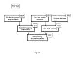
- FIG. 14is flowchart of a method for mapping surround cameras to a pointcloud configured to generate 3D maps from a vehicle according to an embodiment.
- FIG. 15is a flowchart of a method for detecting problematic segments configured to generate 3D maps from a vehicle according to an embodiment.
- FIG. 16is a flowchart of a method for environment analysis configured to generate environment analysis from a vehicle according to an embodiment.
- FIG. 17is a flowchart of a method for driving direction map analysis configured to generate environment analysis from a vehicle according to an embodiment.
- FIG. 18is a flowchart of a method for vehicle surround analysis configured to generate environment analysis from a vehicle according to an embodiment.
- the various disclosed embodimentsinclude a method for analyzing a scene using passive and active measurements.
- the methodincludes using a plurality of image sensing devices in tandem in order to properly render a virtual image of a scene.
- the steps takenmay be adjusted with respect to the current conditions of the scene.
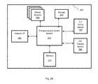
- FIG. 2Ashows an example block diagram of an apparatus 200 configured to generate high-density 3D maps at a video refresh rate, while mounted on a host system, according to one embodiment.
- the apparatus 200includes a memory 215 , one or more high-density video-rate capable passive sensor 230 , and one or more low-density active sensor 220 connected to the processing and control system 210 .
- the apparatus 200further includes a storage 240 , one or more motion sensors 250 , and a network interface 260 connected to the processing system 210 .
- the apparatus 200can be, e.g., mounted on or integrated within a vehicle.
- a vehiclemay be, for example, a car, a truck, a bus, a drone, a robot, and the like.
- the apparatus 200can be utilized to generate high density 3D maps of the scene as would be observed from within the vehicle.
- the apparatus 200is configured to control part or all of the operation of the vehicle based on analysis of the generated 3D maps. Therefore, the apparatus 200 can be utilized in applications related to autonomous vehicles, hands-free driving systems, driver assistance systems, and the like.
- the passive sensor 230may be a video rate high-definition image sensor (e.g., a monochrome or color camera) configured to passively acquire images.
- the acquired imagescan be processed by a processing and control system 210 or inside the passive sensor 230 using image processing techniques.
- the active sensor 220is configured to perform active distance measurements.
- the active sensoris non-controllable, and provides a fixed raster scan of a scene divided into a fixed grid.
- the sensoris controllable, and can be commanded to perform distance measurements on demand, such that the measurement list can be updated from scan to scan, and directed to specific directions to determine the distance of the vehicle from points of interest in the scene.
- the active measurementsare completed using sensors equipped with emitting and detection electromagnetic waves, such as a LiDAR or radar. The distance measurement can be computed based on the travel time from the wave source to the target, e.g., a pedestrian, and back, i.e., when the reflected wave is detected.
- the sensorcan be realized as a time-of-flight (TOF) method, modulation phase delay detection, using a LiDAR or radar.
- active sensor 220can be realized as, but not limited to, an active triangulation, a structured light, and the like.
- the passive sensor 230can be one of a pair of sensors producing distance information using stereovision.
- the processing and control system 210is configured to execute the method described in FIG. 4 . It is configured to process data (e.g., distance measurements, intensity level, direction of the emitted or reflected beam) in order to generate a 3D map of the entire surrounding or visible environment or of certain objects within that environment.
- the processing and control system 210is designed to handle video-rate input and output at a low latency. As part of the process, the processing and control system 210 is configured to control all motion sensors 250 , synchronize between them, and send sensor specific commands to respective sensors.
- the processing and control system 210is configured to send lists of sensor-specific requests to each controllable sensor, including lists of points of interest or regions of interests where an active distance measurement or passive image acquisition is to be performed during a next acquisition cycle.
- the number of active measurementscan be acquired on a specific set of points and/or directions in the scene during an initial scan, through analysis of the image or images acquired by the passive sensors 230 .
- additional informationsuch as previously acquired images or previously generated 3D maps and previously determined active measurements and/or sensory information gathered from the motion sensors 250 , may be utilized.
- the motion sensors 250may include, but are not limited to, a global positioning system (GPS), an accelerometer, a proximity sensor, an odometer, and the like.
- GPSglobal positioning system
- the additional information together with the active and passive sensor measurementscan be utilized by the processing and control system 210 to determine a size of an object within the scene, its speed, and its direction relative to a vehicle.
- the processing and control system 210is a computing unit including a central processing unit (CPU) and a graphics processing units (GPU) in order to support the video rate image processing.
- the processing and control system 210contains optimized software libraries such as OpenCV, CUDA® CUDNN, ImageWorks, and the like.
- the processing and control system 210is designed for executing Artificial Neural Networks, especially Deep Neural Networks (DNN), Convolutional Neural Networks, and the like, for fast and accurate execution of object detection, classification and semantic segmentation.
- the processing and control system 210is an automotive grade, low power high-performance computing system such as the Nvidia® PX family.
- the processing and control system 210 and the implemented software thereonare designed to acquire video rate passive and active data, such that the passive sensor acquires high-density data using a high definition image sensor.
- video data rateexceeds 10 frames per second on the passive sensor and 5 scans per second on the active sensor.
- the high-density formatexceeds 10 pixels per degree angle.
- the processing and control system 210is configured to generate high-density 3D maps in real-time.
- the processing system 210may be configured to fuse active and passive measurements; analyze the 3D map and image to create a list of stationary and moving points of interest; determine stationary or nearly stationary features, segments and objects; actively measure the distance only from features, segments or objects of interest, such as e.g., moving objects; and estimate distance from features, segments or objects.
- the fusion of active and passive measurementsmay include utilizing the active sensor 220 to measure locations where the passive sensor 230 cannot provide a reliable measurement. Whether the passive sensor 230 can provide a reliable measurement for an object may be based on, but not limited to, a classification of the object, a visibility of the object in the image, and the like. In an embodiment, if a reliable passive measurement can be achieved, the active sensor 220 is not utilized. Thus, the disclosed embodiments may significantly reduce the number of active measurements need to be performed by the active sensor 220 .
- the apparatus 200can be configured such that only suspicious targets, such as points, features, segments or objects, will be actively measured using the active sensor 220 .
- a suspicious targetmay be any target that requires active measurement to accurately generate a map based thereon. The analysis, classification of targets, and priority decisioning is discussed below.
- a targetmay require active measurement if, e.g., the target a non-stationary (i.e., moving) and/or in close-proximity to the apparatus 200 . As an example, if the apparatus 200 is mounted on a car, pedestrians will be considered as suspicious objects while trees in the background are not.
- the processing and control system 210is configured to determine which object is stationary or near stationary based on images provided by the passive sensor 230 .
- the processing and control system 210may be configured to determine stationary objects such as, e.g., a house, a tree, a pole, etc.
- the processing and control system 210may be configured to determine if an object is stationary by comparing two consecutive images and determining which objects have been moved relative to stationary objects, based on the comparison. As an example, if the passive sensor captures images from a stationary vehicle, consecutive images may be compared to determine whether any objects in the captured scene have been moved relative to stationary objects.
- determining whether features or objects are stationarymay be based on comparisons of frames (e.g., images) captured by the passive sensor 230 at different times.
- the comparisonsmay include, but are not limited to, determining changes in distances between sets of points or features in the frames, and using the motion data to estimate the motion induced change of position of those points or features.
- each distance change between two pointsmay be equal to a difference between the 3D distance to the points as seen in a first frame with the 3D distance between the points as seen in a second frame. Any point that is determined to have moved may be associated with a non-stationary object.
- an objectmay be determined to have moved if, for example, a sum of all distance changes of points belonging to the object is above a predefined threshold. In another embodiment, an object may be determined to have moved if the sum of distance changes related to the point is greater than the sum of distance changes related to each of the other objects above a predefined threshold. In yet another embodiment, an object may be determined to have moved if a distance change related to an object in a subsequent frame is greater than a distance change related to the object in a prior frame above a predefined threshold.
- the processing and control system 210is configured to analyze the passive images and high-density 3D map in order to generate lists of sensor specific locations for measurements to be passed to each active sensor 220 .
- the sensor-specific liststake into account specific sensors' data, stored in the storage 240 .
- the sensor dataincludes, for example, sensor specifications such as range and field of view; sensor characteristics such as beam size, angular position accuracy, target relative speed, and dead time between measurements; and sensor limitations such as saturation by direct sun light, degradation during rain snow, fog, and the like; side-lobe, and ghosts angles; and the like.
- the processing and control system 210is configured to take the sensors' data into account while splitting the points of interest for active distance measurement into separate lists for separate sensors.
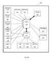
- FIG. 2BA diagram of an example of the apparatus, including sensors, connectivity and data flow, according to an embodiment, is described in FIG. 2B .
- the apparatusis centered around a video-rate real time processor (VRRTP) 270 , configured for real time execution the processing of the method described herein.
- the processor 270can provide a low latency, real-time updated, high-density 3D map 276 and a high-density image 274 at an output rate of above 5 per second.
- the processor 270can support input sensors at acquisition rates exceeding 60 frames per second, and provide a real-time updated high-density 3D map 276 plus high-density image 274 at an equivalent output rate.
- the apparatus of FIG. 2Bcontains one or more front facing high-density passive camera sensors 278 , 280 ; a low-density active LiDAR sensor 282 configured for scanning around the vehicle at 360 degrees; a front-facing low-density active sparse LiDAR sensor 284 configured for focused measurements on targets of interest; side passive camera sensors 292 and back passive camera sensors 294 configured for generating 360 degree imaging when combined with the front cameras 278 , 280 ; a front-facing long-range low-density active radar sensor 286 configured for the detection of range and speed of objects in front of the vehicle; back and side short-range low-density active radar sensors configured for detection of nearby objects around the vehicle; acoustic short rate sensors 290 , arranged to cover all sides of the vehicle and used to detect nearby objects and obstacles.
- the apparatusalso includes a GPS receiver 296 ; an Inertial Measurement Unit (IMU) 295 , including acceleration sensors, leveling sensors, gravity sensors, gyroscopes and the like; connection ports to a vehicles such as a CAN bus 297 for input and output, including receiving the car speed and steering information from the vehicle onboard system; a storage 240 containing the code for implementing the disclosed method and the sensors' data where the configuration, calibration, specifications, performance and limitations of each sensor are stored; a controller sub-section 272 which controls the sensors, handles communications and input and output procedures, high-speed connections for transmission of the sensors data and the output data (not shown); the output of high-density images 274 and a high-density 3D map 276 and high-density cognition data can be transmitted to the vehicle's driving control system at high data rate.
- IMUInertial Measurement Unit
- some of the passive sensors in FIG. 2Bare controllable, and lists of regions of interest (ROI) within the image are referenced to control the acquisition on the next frame.
- the ROI of the passive image sensors 278 , 280can be defined along with binning size to reduce the size of the output image.
- the ROIs of the passive sensors 278 , 280can alternate between un-binned small ROI around a narrow field of view (FOV) enclosing the road in front and a binned wide FOV enclosing the full FOV of the sensor.
- the lists of ROIcan be updated according to a video frame rate, from frame to frame or cycle to cycle.
- Some of the sensorsmay be synchronized such that frames or measurement cycles are acquired synchronously.
- internal clocks of each of the sensors and the processing unit 270are synchronized through control commands.
- Each distance measurement for each frame acquiredmay contain a time stamp of the measurement time, allowing for the temporal alignment of the acquired data.
- the time synchronization and reportsmay provide an accuracy of better than 100 microseconds.
- FIG. 3is an illustration of the placement of sensors configured to generate 3D maps from a vehicle according to one embodiment.
- a front camera 311 and a front-facing LiDAR 313may be placed near the rear-view mirror area of a windshield to provide a desirable view along the driving direction.
- the front camera 311may provide either a mono or stereoscopic high-density, high resolution and high data-rate image acquisition.
- Wide angle fish-eye cameras 321may be placed around the perimeter of the car, possibly facing slightly down, to provide a desirable angle for car parking, lane detection, detection of vehicles in adjacent lanes, and the like.
- the 360 degree LiDAR 324may be placed on a special bracket above the car. Such placement may enable the 360 degree view around the car, possibly at low density coverage.
- a front-facing radar 312may be placed on the car bumper to provide accurate distance and speed measurements to objects in front of the car, covering both short and long ranges. Additional radars 322 may provide surround location and motion information on the objects around the car.
- the ultrasound (US) acoustic sensors 323may be placed on the car bumpers and on the car sides to provide the best distance estimates for a parking car in distances and angles that may be otherwise blind to the other sensors, as well as nearby object detection at the car sides during forward and reverse driving.
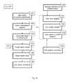
- FIG. 4is a flowchart illustrating a method for generating a 3D map according to an embodiment.
- the methodis an iterative process, where the inputs streams of high-density images from passive sensors and low-density distance measurements from active sensors are processed to generate an output stream of joint high-density 3D map and high density 3D images.
- the processstarts at S 410 by acquiring a passive image, such as an image created by the camera optical sensors 278 and 280 of FIG. 2B .
- an active distance data setis acquired from an active sensor, such as the LiDAR sensors 282 , 284 of FIG. 2B .
- the ADSmay include the distance and speed information each point along a grid imposed on an image. Additionally, the ADS may include distance and speed information regarding various ROIs identified within the image, e.g., vehicles or pedestrians.
- 3D map datais acquired for the scene.
- This datamay be received from, for example, a storage that includes data calculated from previously captured images and information.
- the 3D map datais then aligned and merged with the newly acquired distance data set.
- the alignmenttakes into account a motion transformation, such as the momentary 6-axis motion between subsequently captured frames of the high-density images, including the speed and acceleration vectors and the difference of the time stamps between a first frame and a second frame.
- the alignmentupdates the previously acquired 3D map such that every 3D point in the map shifts by a small amount dictated by the speed and acceleration values in order to accurately represent the position of the measured points relative to the new position of the vehicle at the time of acquiring the new passive image.
- the aligned previous 3D map pointsare merged with the newly acquired distance measurements in a process that discards points that fall out of the acquired range and adjust the accuracy to old points.
- the updated 3D pointsare then upsampled to generate a high-density 3D map at the resolution of the acquired high-density passive image.
- the resulting 3D mapis overlaid on the image to generate the joint output.
- the upsampling processimplements a simple linear interpolation using nearby measurements. In an embodiment, if new distance measurements from active sensors are acquired at different time than the image from passive sensors, then the distance measurements follow the same alignment/propagation process to match the position of the car at the time of acquiring the passive image. It should be noted that the propagation may be either forward or backward in time, depending on the time between the active measurement and passive measurement.
- FIG. 5is a flowchart describing the upsampling process S 450 from FIG. 4 , according to an embodiment.
- the processoccurs at a pixel level, and is repeated for every pixel of interest in the high-density image.
- the high-density 2D image from a passive sensore.g., image 274 from sensors 278 and 280 in FIG. 2B
- a similarity metricto test the visual similarity between each neighboring pixel of a tested pixel.
- the 3D map data acquired at S 430after being aligned and merged at S 440 , is analyzed by testing multiple models for the distribution of the 3D measurements in the vicinity of the tested pixel, and selecting the optimal model per pixel.
- all neighboring 3D pointsare taken into account within a predefined neighborhood; however, each point is weighed according to a calculated angular separation metric.
- Each model for the distribution of 3D measurementsis fitted against two versions: one using only angular metric weights; the other using both angular and visual similarity metrics. For each model, an error is estimated after the fitting.
- the optimal modelis generated based on comparing the errors and applying selection logic accordingly.
- the selected modelis used for interpolating and calculating the upsampled 3D value for the tested pixel.
- this processis repeated for all pixels of interest that remain. If no pixels remain to be analyzed, the up-sampling is completed, and the output is the up-sampled high-density 3D map.
- the similarity metric S 510is performed on a color RGB image. In another embodiment, the similarity metric is performed on a grayscale image. In an embodiment, all pixels in the image are defined as “pixels of interest”. In yet another embodiment, the image and 3D map pass a preliminary processing step before entering the upsampling process of FIG. 5 , where pixels are identified as pixels of interest based on multiple criteria, such as: the non-existence of 3D measurement related to the pixel; existence of measurement values for the pixel, but the values contain large inaccuracies or low validity values; and the like. In an embodiment, the upsampling is carried out at subpixel resolution to match the exact center or other predefined position inside the pixel.
- one of the models tested in S 510is fitting to a plane, and the output contains the plane normal vector.
- a planemay indicate a road surface, a wall or the surface of a vehicle.
- one of the models tested in S 510is fitting to a random cloud of points, and the output contains the size of the cloud.
- Such a cloudmay indicate a tree.
- one of the models tested in S 510is fitting to a curved surface. Such a curve may indicate a rounded object or vehicle surface.
- two or more interpolated valuesare calculated in S 510 from two or more models, such as plane model with and without a visual similarity metric. Such cases are required for later processing of the results to identify surfaces with non-similar patches that belong to the same object or surface, as in the case of road marks and multi-colored objects.
- FIGS. 6A-6Care flowcharts representing the method of generating points of interest (POI) and requests lists for each active sensor according to an embodiment.
- a high-level methodis shown.
- the POI generation processreceives, as an input, the current maps of a scene, including a high-density 3D map and a 2D image, as well as previously stored maps, such as accessed from a storage.
- the input mapsare analyzed to identify POIs as explained in FIG. 6B .
- the POIsare then analyzed to set priority levels for each POI at S 610 .
- the POIsare then split per available controllable sensor, based on an input data of sensor characteristics.
- the requestsare ready to be transferred to each controllable sensor.
- the analysis to set priority level (S 610 )is performed by allocated pre-defined priority levels to each category of POIs, and sorting the detected POIs by category.
- the POI listis a list of angular-coordinates.
- the POI listis an angular map where each pixel is given a priority level.
- the POI listis a list of rectangular regions of interest (ROI).
- the priorities of different categories for a specific POIare joined using a predefined mathematical formula such as adding, multiplying, and selecting the maximal value.
- the status reportmay be an alert of low-visibility conditions. In another embodiment, the status report may be an alert of a malfunctional sensor.
- the host driving system or human driverupon detection of malfunction conditions, are notified by an alarm message, to inform the driving system to drive slower to allow the remaining sensors sufficient time for safe detection of obstacles and road.
- FIG. 6Bis a flowchart for a method of analyzing the input maps in order to identify POIs and their respective categories and priority levels S 610 according to an embodiment.
- Each categoryis a unique identifier that keeps record of the method that was used to identify each POI.
- One example of a POI identification analysisis by identifying “holes” of missing data in the high-density 3D map (S 620 ). These holes may be the outcome of having no distance data at a predefined angular distance from the specific point, of from having an interpolated result with a high estimated error or low significance value.
- a further example of POI identification analysisincludes detecting features of interest in the image, such as edges, patches, visually distinguishable segments or super-pixels.
- moving features of interest within the imageare detected, such as moving edges, moving key-points, moving scale-invariant feature transform (SIFT) or moving patches.
- SIFTmoving scale-invariant feature transform
- POI identification analysismay further include detecting the distance of features or objects using stereoscopy from motion process in the image. This involves using two images captures from the same sensor at two close points in time, or using two images generated at the same point in time from two different sensors. Comparing such images allows for the calculation of the distance of the object or feature.
- a further example of POI identification analysisinvolves detecting objects and extended objects through semantic segmentation of the 3D map and 2D image, through unsupervised 3D processing or supervised trained neural network.
- yet a further example of POI identification analysisincludes detecting isolated objects through object detection on the 3D map and 2D image, using unsupervised 3D processing or supervised trained neural network. Additional information allowing POI selection is provided through an object classification algorithm at S 632 , either through supervised or unsupervised classifier.
- Another example of POI identification analysisis by tracking objects from frame to frame ( 634 ) through object tracking algorithm.
- the analysis for detecting POIsfurther includes analyzing and detecting local or global low-visibility angular regions in the passive image, or using one of the active sensors, or both.
- regions of low visibilityare identified as being too dark to contain useful information, such as unilluminated regions, dark tunnels or structure, low-reflectance targets, and the like.
- low visibility regionsare identified as being saturated. Saturation may be the result of overexposure, flare from the sun or another light source, and the like.
- low visibility regionsare identified as having intermediate intensity level, but with very low contrast and low color contrast. Such low contrast may indicate a situation of fog, rain, snow, dust storm and the like.
- low visibility regionsare identified as having strong clutter at short ranges on an active LiDAR sensor. Such conditions may indicate, for example, heavy rain or snow that reflect the pulsed light back to the sensor and which is being detected instead of the remote target.
- the state of visibilityis analyzed and stored separately for each sensor, allowing the next method disclosed in FIG. 6C to either adjust operational parameters or modes of the sensor, or otherwise focus detection attention of other sensors in directions where one sensor suffers from low visibility.
- low-visibility regionsare identified as a malfunction in a sensor, based on the length of time the area is detected as comprising a low-visibility state.
- radar detectionsare cross checked with the image in order to identify suspicious ghost detections in situations where there is no object visible at the location reported by the radar. Such ghost detections may indicate a reflection due to a side lobe of the main radar beam, and requires cross validation by a second radar beam or by a LiDAR to confirm the objects within the scene.
- the POIis a rectangular ROI, identified as a region requiring special attention.
- the rectangleis defined by analyzing the 3D map to identify the angular region enclosing the road behind a specific distance, such as, for example, 50 meters from the sensor.
- the rectangleis defined by analyzing the 3D map to identify the angular region enclosing groups of pedestrians that require more details.
- the rectangleis defined by analyzing the 3D map to identify the angular region enclosing low-light or saturated light areas.
- FIG. 6Cdescribes the various steps taking in splitting the identified POIs S 615 per available controllable sensor, based on the category of the POI as described in FIG. 6B and the sensor characteristics.
- POIs of saturated camera image pixelsare defined as locations to be measured by a radar and a LiDAR.
- POIs of dark camera image pixel regionsare defined as locations to be measured by a radar and a LiDAR if the passive optical image provides insufficient data to accurately analyze the scene.
- POIs of low contrast image pixels regionsare defined as locations to be measured by a radar and a LiDAR to provide additional detail.
- POIs of remote targetse.g., beyond the range of one sensor but within the range of another sensor, are defined as locations to be measured by a longer-range sensor, e.g., a radar having a longer range than a LiDAR, or vice versa.
- POIs identified as belonging to a moving objectare defined as locations to be measured by a radar or by using a specific LiDAR pattern designed to capture the object even if the motion of the object is not accurately measured.
- POIs identified as features of interest or objects of interest for a LiDARare defined as locations to be measured by a LiDAR, since a distance information is missing or inaccurate.
- ROIs of interestare defined as ROI to be measured separately by a super-high-resolution passive image sensor, if such exists with the system, since the normal resolution is insufficient for detecting or classifying the object.
- locations on and around a low-resolution radar detectionare defined as locations to be measured using a gated mode of a LiDAR, if such exists, as defined in the sensor data.
- POIs of large planar surfaces segment regionsare defined as locations to be measured sparsely by a LiDAR, as is the case for roads, ground and walls.
- POIs of small objects on the roadare defined as locations to be measured densely by a LiDAR.
- POIs of objects that are identified as being very close to the vehicleare defined as locations to be measured by an acoustic sensor.
- POIs of large tracked moving objectsare defined as locations to be measured by a speed measuring radar; POIs of dark locations are defined as locations to be actively illuminated by a controllable spot-light projector; conditions of malfunction of one sensor are defined as conditions to use other sensors in a special optimal scan mode instead of the default mode; upon identifying conditions of malfunction of a passive sensor, the LiDAR and radar will be operated in a systematic raster scanning for optimal detection, instead of measurements on demand; upon identifying conditions of malfunction of a LiDAR, the LiDAR POI's are transferred to the radar, and vice versa, and the like. Additionally, the method may include using multiple sensors to detect and analyze a single POI, as well as utilize three or more sensors for the detection of the 3D space within the captured scene.
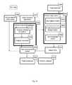
- FIG. 7is a flowchart of a method 700 configured to generate an environment analysis from a vehicle according to an embodiment.
- the input from sensors 701 - 703may be processed to generate a 3D map, which may be further processed into an environment model that can be used to generate driving instructions.
- the computer elements in vehiclesare typically enclosed in an electronic control unit (ECU) which are subject to additional design considerations such as optimal shape factor, performance and redundancy.
- the units described in FIG. 7may be further distributed into one or several ECUs based on specific application requirements.
- the 3D mapcan be generated by a first ECU
- the environment modelcan be generated by a second ECU and driving instructions can be calculate by yet another ECU.
- driving instructionscan be calculate by yet another ECU.
- a front-facing 3D map and modelcan be generated in one ECU, while the surrounding information may be processed in another ECU.
- Some ECUscontain processing units with CPUs (central processing unit), GPUs (graphics processing unit), TPU (tensor processing unit) and dedicated ASIC units that can be dynamically configured to perform some of the functions in FIG. 7 .
- Controllable sensors 701may be configured to acquire specific spatial segments based on the analysis of the environment. Fixed sensors 702 have a fixed FOV (field of view), and cannot be configured to point in a different direction. Other sensors 703 do not have a specific FOVs and provide some contextual information. All sensor inputs may be processed by a sensor control unit 704 . Sensor control unit 704 may also be configured to control the acquisition parameters of the sensors, to send some directional commands to some sensors, and to configure the FOV for controllable sensors 701 . Sensors and the sensor control unit are further described in FIGS. 8 and 9 .
- Sensor input streamsmay arrive at different times and from different spatial segments. It may be beneficial to realign multiple inputs from different sensors to common coordinates, taking position of the sensors and time of capture into account.
- a front-facing camera FOV and timemay be used as the reference point for a driving direction, while a LiDAR location and time may be used as the reference point for a model of the surrounding environment.
- the camerasare further registered to some location and orientation central to the vehicle.
- Other non-image sensorssuch as GPS and inertial measurement units (IMU) sensors, may be calibrated to the selected location within the vehicle and aligned using a common timestamp.
- a motion compensation unit 705may compute all the relevant temporal and spatial transformations as is further described in FIG. 10 .
- a spatiotemporal adjustment unit 706may prepare and aggregate the relevant information from a plurality of sensors for further processing.
- the inputs of the spatiotemporal adjustment unit 706may include asynchronous streams, while the output may be a synchronous frame.
- the spatiotemporal adjustment unit 706is further described in FIG. 12 .
- the frame output from the spatiotemporal adjustment 706may be further augmented via geospatial information 708 available from other sources, including maps, v2v (between vehicles or between a vehicle and infrastructure) communication, advertising and other similar information channels.
- geospatial information 708available from other sources, including maps, v2v (between vehicles or between a vehicle and infrastructure) communication, advertising and other similar information channels.
- We call the resulting augmented framea “3D map” of the environment, and it may include a high-resolution map of the area, the static and moving objects in the area with relevant location and speed estimates, road and traffic signs and signals, free space available for driving segmentation and other relevant road information.
- this informationmay be further modified via an environment mapping unit 707 , further described on FIGS. 13-16 , into the front-facing high-resolution map and surround low resolution point-cloud.
- the front-facing high-resolution map and surround low resolution point-cloudmay be further analyzed by an environment analysis unit 709 , also described on FIGS. 17-18 .
- the environment analysis unit 709may generate an environment model in a format that enables driving decisions and alerts by a driving assistance unit 710 .
- the environment model generated during operationcan be configured to identify changes between the supplied geospatial information 708 and the actual environment as described by the actual model, and to send these changes back to the geospatial information center, to enable real-time updating of the changes made to the environment.
- FIG. 8is a block diagram of exemplary sensors for an apparatus configured to generate 3D maps from a vehicle according to an embodiment.
- the controllable sensorsare directed to face the driving direction, while the fixed sensors provide surround coverage at the sides and read of a vehicle.
- the decision-making processmay include slowing down the vehicle, evasive maneuvers, handover of the operation of the vehicle to a human driver, scanning an area of interest in superior resolutions to further assess its properties, and other controllable actions.
- small objectssuch as bricks may generate a significant damage while hitting the vehicle and must be properly identified.
- controllable front sensors 810offers a viable solution.
- a camera with controllable regions of interest (ROI)may be used.
- the controllable ROIis a feature available in some sensors than enables partial use of the sensor area and results in lower communication bandwidth.
- the integrated signal processing (ISP) board of the sensoralso enables resampling and the sensor may support analog binning to increase the SNR (signal to noise ratio).
- a thermal cameramay be used for better visibility in night light.
- RGB colorscan be mixed with other spectral modalities to enable better visibility in a wide range of conditions.
- the mix mode of the sensorsmay be further controlled by a sensor control unit 704 .
- Many ISPscome with built-in HDR (high dynamic range) mode, denoising and contrast enhancement algorithms, and may improve the image quality in deteriorating visibility conditions if instructed to do so. However, such modes may introduce artifacts reducing the effective camera resolution.
- a radarsuch as a phase array radar 812
- Phase array radarsmay be digitally configured to detect as some configurable one dimension or two-dimension angles, including full or partial scanning of the space in front of the vehicle. Unlike a camera sensor or a LiDAR, radar is less sensitive to rain, dust, snow and other atmospheric conditions as well as illumination. Objects can often have a different reflectivity to radio waves than to visible light and infrared spectrum. Thus, a phase array radar may generate a low-resolution 3D map of the environment in front of the vehicle that may otherwise be invisible or difficult to capture using other sensors.
- controllable LiDAR 813may be used to analyze a scene.
- MEMS (microelectromechanical systems) LiDARsmay be economical and highly configurable, and may be provide better scanning rate and angular resolution than other types of LiDARs. MEMS LiDARs can provide an accurate high frame rate, high resolution 3D mapping of the area in front of the vehicle. LiDARs with polygon mirrors may also be used for similar purposes. Operating a LiDAR in a Multiple-point per pulse mode allows LiDARs to ignore some atmospheric interference, while reducing the effective sampling rate of the LiDAR.
- different types of front facing sensorsmay be calibrated to the frame of reference of the front camera 811 .
- This sort of registrationminimizes imaging artifacts in the camera plane, enabling implementation of effective depth-aware image processing algorithms, including ego motion (three-dimensional motion of the camera) detection, object detection, road segmentation, road signs recognition, traffic lights recognition, lanes detection, pedestrian detection, obstacle detection and classification, vehicle detection and tracking, and other image processing algorithms.
- ego motionthree-dimensional motion of the camera
- Pointing algorithmsmay be used to configure LiDARs and radars to provide frequent and high-resolution scans of objects suspected to be important for driving decisions. Objects that are poorly lit for image sensor may be multiply sampled by LiDAR or Radar for providing more reliable reading. Pointing algorithms may balance the needs of different subsystems to provide the best viable scanning plan at each timeframe.
- Fixed sensors 820may be configured to provide surround coverage of a vehicle. These fixed sensors may further be configured to help avoid collisions directions not visible to the front sensors 810 . While several fixed sensors can be used to provide full 360-degree coverage, doing so can be cost-prohibitive. Moreover, these sensors often provide a very wide FOV, resulting in reduced sampling rate and resolution.
- a 360-degree scanning LiDAR 823may be used to evaluate distances to the surrounding objects.
- the price of the LiDARis proportional to the number of individual sensors, which in turn is proportional to its vertical resolution. Since these LiDARs can be expensive, reducing the vertical resolution of the LiDAR 823 provides an option for reducing the overall system price.
- 360-degree visual coveragemay be provided by using several wide-angle cameras 821 .
- some embodimentsuse four fisheye cameras using the four principal directions.
- the effective resolution of the fish-eye cameramay be lower in the corner areas farther away from the optical center.
- the overlapping area between the camera imagesmay be used to calibrate the intensity levels of the cameras.
- the camerasmay be further calibrated to project the image onto a single point on the vehicle, such as the location of the LiDAR 823 .
- a stereo from motion (SFM) algorithmmay be executed on the cameras 821 , enabling depth measurement of multiple objects not directly visible by a LiDAR 823 .
- the vehiclemay be fitted with a wide range of blind spot, collision alert and rear facing radars 822 .
- These radars 822may provide the distance to the closest objects in the relevant direction and the speed of these objects.
- Ultrasonic (US) distance sensors 824may provide distance measurement in areas not visible by other sensors, such as distances less than 1 meter from the vehicle. For example, 4 US sensors may be used in the rear of the vehicle and 2 sensors in the front to provide close object detection. The US sensors may provide slow reaction speed and low maximal distance, encouraging their primary use for parking and orientation in the space previously mapped by other sensors.
- the location of the vehiclemay be tracked via GPS 831 , while its acceleration may be monitored via an IMU.
- magnetometersare also used to indicate the direction of north.
- These geospatial sensors 830provide additional cues to the environment model.
- the GPS sensor 831may eliminate drift in motion estimation and provide localization for some maps.
- the IMU 832 sensormay indicate if the vehicle is moving, including possible bumps of the road. It may be further used to determine the stabilization of the environment map with respect to 6DOF (degrees of freedom:3 linear speeds axes, 3 rotation speed axes) vehicle movement.
- Additional sensor informationmay be provided via CANBUS (controller area network bus) 840 .
- This informationmay include geospatial cues 841 from external services, such as V2V communication 851 , maps 852 , local services and ads 853 .
- Odometry 842 readingsmay supply information about the wheels of the vehicles, enabling better determination of vehicle location and speed, traction of the road estimation, the reaction speed of the vehicle mechanisms and additional parameters.
- Driver status 843such as driver eye tracking, enables information about the driver, for example if the driver is not sufficiently alert to avoid a danger or receive the control over the vehicle.
- Driving commands 844may be issued for vehicle turning, starting, stopping, following a path on the map, performing parking and other driving activities.
- FIG. 9is a flowchart of a method for sensor control configured to generate 3D maps from a vehicle according to an embodiment.
- the sensor readingmay be acquired from the relevant stream 901 .
- the readingmay be further rectified 902 using various calibration data.
- Each sensormay have internal calibration data from the measurement to the world coordinates and external calibration data to the coordinates of another sensor. Fisheye and other distortions of the cameras are corrected. Contrast and gamut correction can be applied to the cameras.
- the coordinate systemsmay be transformed 903 . Projective transform and 4 ⁇ 4 matrix may place depth data on the relevant camera and vice-versa.
- each sensormay use a different time reference, and the whole system may use yet another time reference, the synchronization of multiple clocks 904 may be necessary to integrate various system components. This calibration may be further refined using various system readings, since a rare event should happen in all sensors approximately at the same time.
- Some sensorshave a slow sampling speed and provide a timestamp per reading. These sensors may require several readings to be unrolled 905 to the same time.
- transformations 903 and 905may use motion estimation and provide a variable transform per sensor reading.
- Some framesmay become invisible when captured by certain sensors.
- the visibilitymay be analyzed 908 to determine areas of low contrast, high noise, overexposure and underexposure. For example, a minimum, maximum, mean and standard deviation reading may be calculated for values captures within an image. For example, intensity readings of a LiDAR or a radar derived image may be analyzed as such. Additionally, there may be a communication problem, such as a malfunctioning sensor, which can be determined by monitoring the communication channels 910 and determining the channels having no signal or high communication noise.
- corrective measurementsmay be used in cases of poor visibility or sensor malfunction.
- the vehiclemay be instructed to slow down.
- Some of the corrective measures 909 - 911may apply during the sensor acquisition. Namely, which sensor are to be used for image capture can be adjusted 909 , the global intensity may be changed 910 and denoising algorithms (such as a non-local means) 911 may be activated.
- Pointing algorithmsmay generate a set of pointing instructions that may be read 906 , to instruct specific sampling in the areas of interest. For example, in areas of low useful signal, larger integration time may be used. In areas with larger motion, more frequent sampling employed. In areas with small objects, a denser sampling may be used for more accurate detection. These sampling points may need to be taken using predicted coordinates of the sensor 1407 after the point set creation. For these measurements 907 , as well as other measurements, the sensor mode 909 may be modified for a different integration time, multiple return mode, sensor binning, high dynamic range or other mode as required.
- FIG. 10is a flowchart of a method for motion compensation configured to generate 3D maps from a vehicle according to one embodiment.
- the vehicle motionis taken into account for accurate coordinate transformation calculations using the sensor control unit 704 .
- the calculationsmay use several data sources with uncorrelated noises and a filter tuned to filter out the relevant noises.
- a filtertuned to filter out the relevant noises.
- an extended Kalman filter 1004may be applied to the captured image to remove the noises of various filters adaptively. Since a vehicle can have only a limited acceleration in 6 degrees of freedom (DOF), an extended Kalman filter of the second order in the 6 DOF may be used.
- the filtermay be further tuned to evaluate the road traction, residual calibration errors and other error functions for autocalibration, self-diagnoses and road status estimation.
- the filter 1004may access the vehicle odometry reading from the car wheels, car acceleration from IMU 1002 , global position from GPS 1002 .
- the current motionis typically predicted based on the previous motion estimations 1003 . This motion may be later updated using camera and depth readings, which may be used to predict the current pointcloud 1005 .
- the RGB image stream from the camerasmay be further interpolated 1006 to the pointcloud location. These locations can be further refined using feature tracking, which may be calculated 1011 using an appropriate detector, such as a Harris, DoG or Lucas-Kanade-Tomasi tracker. These features may be characterized using SIFT, SURF, ORB, FREAK or other suitable descriptors.
- Descriptor matching 1012may be used to characterize the motions of the vehicle and of other objects. Different confidence may be applied to features with depth readings and features without depth reading. If too few features are found in a given locality, additional features may be found using a different detection threshold. If too many features are found, or features are found bit do not result in a positive identifying match, the features may be ignored or removed.
- the feature algorithm 1013may be analyzed for statistical behavior to predict a tracking error and adjust the motion refinement 1014 accordingly.
- An optical flow 1007may provide a direction of motion for different objects in a camera plane. This motion may be further segmented 1008 based on the detected motion of different planes within the image. The segmentation can employ optical flow, normal XYZ space, RGB color, and other parameters to detect planes of similar qualities.
- the vehicle motion 1009may be further refined to exclude the moving segments. For each moving segment, its own motion model may be refined 1010 . The system may track the segments and change segmentation gradually in 1008 to confirm with some physical model of the objects in the scene and their occlusions.
- FIG. 11is a flowchart of a method for spatiotemporal adjustment configured to generate 3D maps from a vehicle according to one embodiment.
- a frameis mapped 1110 to include relevant data from multiple streams.
- the data relevancymay be defined by time limits and the available FOV. Since different sensors may have different frame rates, there may be zero or a plurality of readings in a given time frame. These readings may need to be extrapolated or filtered.
- a framemay include a camera frame, a radar reading, and a LiDAR scan mapped to the time of the camera reading.
- the relevant timingis the calculated timing of the output mechanism 1112 , which may correspond to the timing of the sensor of reference, such as front facing camera or 360-degree LiDAR, or may be adapted to adjust for clock jitter and frame skips.
- the time difference that needs to be compensated per streammay be calculated in 1113 .
- the motion estimations for the segments of interestmay be applied 1112 to predict the locations of the given segments 1614 .
- high levels of accuracymay be required.
- the systemmay apply a plurality of interpolation methods, choosing the method with highest confidence, including na ⁇ ve averaging, 3D spatial interpolation, bilateral filter using spatial and RGB features, patch match or other suitable methods.
- the interpolation errormay generate an additional map that can be used as spatial confidence in object segmentation.
- the datamay be aggregated for long periods of time 1121 , as long as the motion is consistent.
- the LiDAR datamay be aggregated for up to 20 frames so long as the motion is consistent.
- the confidence of older readingsmay be gradually reduced due to aggregated error in motion estimation.
- the newer readings with higher confidencemay replace the older readings.
- the computationmay be performed with subpixel accuracy and provide super resolution according to a calibrated point spread function and computed motion trajectory.
- any inconsistencies detectedshould be removed 1122 , including the phenomena of background depth layers hiding behind the foreground layers.
- separate memories for several layers of graphical informationmay be employed.
- some segmentsmay have poor reflective properties, and may be interpolated using the segment edges. In the areas of depth texture, such as trees, the depth reading may be inconsistent.
- the algorithmmay be configured to filter out the background readings in such areas. There may be standalone depth measurement due to returns from dust and other malfunctions. These depth measurements may have no support in camera or radar readings and may be removed.
- stereo from motionmay be calculated using the motion model of the features or image segments and after the inconsistency filtering. By using features aggregated from several readings 1121 , the stereo measurement quality may be improved. This sort of stereo from motion may be used for example in the areas not covered by direct and accurate LiDAR and radar readings.
- FIG. 12is a flowchart of a method for environment mapping configured to generate 3D maps from a vehicle according to one embodiment.
- the process in FIG. 11may be applied to several data sources as a group, or to each data source separately.
- the radar data and the LiDAR datamay be aggregated separately using the same image data.
- the image datamay change in the process due to ROI modification or a similar mode change.
- wemay ensure that there is camera frame 1211 , LiDAR frame 1212 and radar frame 1213 to work with. If there is no relevant frame, an empty frame may be used.
- mapping algorithmsthat may be applied to the driving direction and the surround direction respective of the vehicle.
- depth maps from camera and radarmay be interpolated to have per pixel readings 1221 .
- pointing setmay be calculated 1222 to control the sensor pointing.
- the surround mappingseveral cameras may be used. Therefore, it may be advantageous to map the camera color reading and the radar velocity reading to the point-cloud of the 3D space, or the occlusion grid 1231 .
- the occlusion gridthere can be confidence level per voxel based on consistency of LiDAR, radar and stereo from motion readings.
- motion datait may be advantageous to use occlusions and parametric object motion estimations.
- FIG. 13is further a flowchart of a various steps for mapping depth to a front camera configured to generate 3D maps from a vehicle according to one embodiment.
- the depth coordinatesare projected to camera coordinates 1321 .
- the depth coordinateswill be unknown, and some will get several undesirable measurements due to occlusions.
- Selected interpolation weights 1330include several weight models, such as bilateral filters, non-local means, patch match or na ⁇ ve averaging using local segmentation, spatial data, spatial speed reading, and color data.
- the color weights 1331may be calculated in RGB, HSV, grayscale, opponent colors or other color domain.
- the spatial weights 1332may be calculated using 2D projection data on the camera plane and 3D point-cloud data.
- the calculation of radar compared to LiDAR weights 1333may be adapted for the atmospheric conditions and local reflectivity.
- Weather conditionsmay be estimated 1334 using global statistics on noise, contrast, intensity, and other statistics.
- Intensity artifactssuch as flare may include computation of local statistics and further projection of these statistics using some physical model such as fitting diffusion equations to intensity profile 1340 .
- FIG. 14is a flowchart of a method for mapping surround camera images to a point cloud configured to generate 3D maps from a vehicle according to one embodiment.
- surround camerasare rectified to target views, where each camera may be rotated differently to achieve a desired position.
- the camerasmay be rotated to a 3D location comfortable for projection into a target point, including for example 90 degrees between planes of rectified cameras, fisheye and other distortion correction, ensuring epipolarity of cameras and imposing other criteria via relevant calibration.
- the depth of an objectcan be mapped for each camera direction 1422 , so that each camera pixel gets an XYZ value associated with it. Since the position of XYZ values on the camera plane may be subpixel, complex interpolation may be used, including joint bilateral interpolation, non-local means and patch matching. In some embodiments, the interpolation may also return the interpolation confidence.
- a coloris selected per voxel 1423 by mapping the camera colors back into the XYZ grid. Since a given voxel may get color from several cameras, a conflict resolution may be used to produce a useful result, including selection of the color with the best confidence score.
- an occupancy gridis calculated 1424 by evaluating the chance that each voxel is occupied.
- the occupancy of each voxelmay be tracked between frames using object motion estimation. For example, a voxel may be visible in some frames, occluded in other frames, and appear on edges in yet other frames.
- Ultrasound sensorsmay be used to fill in the occupancy grid in areas invisible by the other sensors. Since the resolution of radars and ultrasound sensors may be lower than the grid resolution, the chance of occupancy in the relevant voxels may be filled by the error spread function of the relevant sensors.
- the voxel speedcan be calculated 1425 by using some tracking over occupancy grid, parametric motion model and radar readings. Different algorithms may be used for rigid objects like cars and non-rigid objects like pedestrians.
- FIG. 15is a flowchart of a method for detecting problematic segments configured to generate 3D maps from a vehicle according to one embodiment.
- the intensity levelsare analyzed in order to detect areas with different reflection patterns. Segments with low or noisy reflection patterns may vary in RGB, infrared and LiDAR lights. There may be several threshold levels for each parameter to enable better clustering of problematic measurements. These segments may be further grouped using connected components algorithms.
- non-reflective planesare masked so that the depth measurements behind these planes get occluded.
- non-reflective planeswill still have reflective edges or reflective readings in other wavelengths, which enable masking.
- a different sort of problematic segmentsmay be generated by broken planes. Find the planes via local normal in a gliding window 1521 . Plane motion can be evaluated 1522 to remove artifacts inconsistent with motion model, such as measurement noise.
- Some treesgenerate fractal edges both in 3D and color. These edges may be detected 1530 via local variance analysis and masked to the foreground depth.
- Different segmentsmay form 3D objects and correspond to a physical motion mode, including rotation and translation with some limited acceleration.
- non-physical jittermay be eliminated.
- FIG. 16is a flowchart of a method for environment analysis configured to generate environment analysis from a vehicle according to one embodiment.
- the environment analysismay extract instances of different kinds of objects and their properties.
- Objects of interestmay include cars, pedestrians, cyclists, road, lane markers, free space for driving, traffic signs, traffic lights, junctions, static or moving obstacles on the road, or other types of objects.
- Some instancesmay be tracked in time, while other instances may be new and may require detection. Some instances my cross from the surround maps to the driving map, or from the surround map to the ultrasound detection area. Some instances may be partially and temporarily obstructed by other objects, such as trees. In some embodiments, behavioral analysis of instances may be required, e.g., a pedestrian breaking away from a group, including a child running away from their parent; a car attempting to turn, and the like
- Some instancesappear in multiple locations, including far and close locations, so the aggregate information about the instance may be more significant than the information in a given time period. Therefore, it may be useful to track each instance without losing the instance and redetecting it as another instance of a given object type.
- the systemmay use the motion model of the instance and predict the instance locations at a given time 1601 . This prediction may be compared to the actual detection and tracking results of the instances 1602 and the instance model may be modified accordingly using, for example, an LSTM neural network or extended Kalman filter.
- the physical model of the instance of interestmay be further used to predict the instance behavior 1603 using heuristics or trained artificial intelligence mechanism.
- Feature trackingmay be also performed using rigid surfaces and invariant characteristics, such as height, color histogram, color distribution by height. Since people use different colors of cloth for different body parts, and cars use different colors for wheels, body and windows, the color distribution by height may remain relatively consistent for a moving object.
- the front-driving frame analysismay be different from the surround analysis and may be performed by a separate ECU.
- the analysis resultsmay be later used to calculate an environment model 1630 for a given region of interest.
- the region of interestmay exclude areas that are not drivable and do not contain instances of the interesting objects.
- the ROI selection 1670may use various features to mask the areas that are excluded from analysis. This masking may be useful to remove highly segmented and noisy data and to reduce the communication and computation toll of the system.
- the ROI selection 1670may be used to switch analysis mode including switching between computational expensive high-quality processing and computationally easy processing
- the data from the front facing frame, surround pointcloud and other data sourcesmay be further fused 1660 to create a viable model of the environment.
- the fusionmay be performed in several modalities. For example, the fusion may be performed per feature of interest 1661 , per imaging modality 1662 , including fusion of RGB and thermal cameras or LiDAR and radar.
- the fusionmay be performed per spatial area, including pointcloud fusion 1663 .
- FIG. 17is a flowchart of a method for driving direction map analysis configured to generate environment analysis from a vehicle according to one embodiment.
- the analysismay be performed using a combination of plurality of heuristics and artificial intelligence methods. These methods may include analysis of local normal, mean shift of Hierarchical Density-Based Spatial Clustering of Applications with Noise (HDBSCAN) clustering, convolutional neural networks, RNN (recurrent neural networks), neural networks with LSTM (long short time memory) layer, and probabilistic networks such as CRF (conditional random fields). Some of these methods may be configured to implement object detection, object mask detection, instance aware semantic segmentation, classification or other useful analysis.
- HDBSCANHierarchical Density-Based Spatial Clustering of Applications with Noise
- RNNrecurrent neural networks
- LSTMlong short time memory
- CRFconditional random fields
- a bird's-eye view of the scenemay be calculated by interpolation by projecting the 3D maps on the plane of the road or alternative manifold characterizing free space for driving.
- the interpolationmay use subpixel information for distant objects and local normal to interpolate the data along the normal.
- the local normalmay be created by analyzing the gradients in a moving window in camera plane and segmenting the planes with gradients similar to the gradient of the central pixel of the frame. Both spatial and texture gradients may be used for the analysis.
- local featuresare extracted per pixel, including pixels that may be detected by a trained artificial intelligence mechanism.
- roadsare detected based on analysis of the bird's eye view or based on the extracted features.
- road lane markersare detected. In some embodiments, environmental cues, such as other cars, may be used to suggest lane markers hidden from the vehicle's cameras.
- Cars, pedestrians, cyclists and other objectsmay be localized by object detection within some 2D or 3D boxes at 1721 . This information may be further used to create masks per each instance 1722 and enable analysis of occlusions of different objects.
- anomalies in the roade.g., a child may throw a ball, something may fall from a truck or an animal may cross the road. These anomalies may be detected at 1715 for further analysis.
- the anomalies and instances of known objectsmay be further classified at 1730 , where the classifier may use statistics of pairwise occurrence of different objects, annotated images from web search, or other useful statistics.
- the road signsmay be classified and identified 1731 . These road signs may be further correlated with a map or may serve as driving instructions in unmapped situations.
- Groups of instances of objectsmay also be analyzed at 1741 for group behavior. This may include car convoys, demonstration, parents with children, children playing, people on horses and other complex groups.
- the entire scenemay be classified at 1742 , for example as a park or as a highway, or as a parking lot or as a city road or as other suitable classification.
- the scene classificationmay be further used to refine the other detection tasks.
- FIG. 18is a flowchart of a method for vehicle surround analysis configured to generate environment analysis from a vehicle according to one embodiment.
- the high resolution, frequently updated driving direction mapmay be considered together with the surround point-cloud occupancy grid for several driving tasks as follows.
- the moving objectscan be segmented separately from objects currently not moving and speed and direction of the movement may be estimated at 1801 .
- Space free for drivingmay be detected at 1802 .
- the drivingmay occur within this free space and may include emergency maneuvers to avoid collisions, at 1811 , of path planning according to map analysis at 1803 or parking space analysis at 1802 .
- Driving recommendationsare generated at 1822 and may include communication with other devices, alerts, activation of gas, break and steering wheel and other useful operations.
- the phrase “at least one of” followed by a listing of itemsmeans that any of the listed items can be utilized individually, or any combination of two or more of the listed items can be utilized. For example, if a system is described as including “at least one of A, B, and C,” the system can include A alone; B alone; C alone; A and B in combination; B and C in combination; A and C in combination; or A, B, and C in combination.
- the various embodiments disclosed hereincan be implemented as hardware, firmware, software, or any combination thereof.
- the softwareis preferably implemented as an application program tangibly embodied on a program storage unit or computer readable medium consisting of parts, or of certain devices and/or a combination of devices.
- the application programmay be uploaded to, and executed by, a machine comprising any suitable architecture.
- the machineis implemented on a computer platform having hardware such as one or more central processing units (“CPUs”), a memory, and input/output interfaces.
- CPUscentral processing units
- the computer platformmay also include an operating system and microinstruction code.
- a non-transitory computer readable mediumis any computer readable medium except for a transitory propagating signal.
Landscapes
- Engineering & Computer Science (AREA)
- Remote Sensing (AREA)
- Radar, Positioning & Navigation (AREA)
- Physics & Mathematics (AREA)
- General Physics & Mathematics (AREA)
- Computer Networks & Wireless Communication (AREA)
- Electromagnetism (AREA)
- Theoretical Computer Science (AREA)
- Geometry (AREA)
- Software Systems (AREA)
- Computer Graphics (AREA)
- Multimedia (AREA)
- Traffic Control Systems (AREA)
Abstract
Description
Claims (20)
Priority Applications (1)
| Application Number | Priority Date | Filing Date | Title |
|---|---|---|---|
| US15/892,039US10445928B2 (en) | 2017-02-11 | 2018-02-08 | Method and system for generating multidimensional maps of a scene using a plurality of sensors of various types |
Applications Claiming Priority (2)
| Application Number | Priority Date | Filing Date | Title |
|---|---|---|---|
| US201762457818P | 2017-02-11 | 2017-02-11 | |
| US15/892,039US10445928B2 (en) | 2017-02-11 | 2018-02-08 | Method and system for generating multidimensional maps of a scene using a plurality of sensors of various types |
Publications (2)
| Publication Number | Publication Date |
|---|---|
| US20180232947A1 US20180232947A1 (en) | 2018-08-16 |
| US10445928B2true US10445928B2 (en) | 2019-10-15 |
Family
ID=63105328
Family Applications (1)
| Application Number | Title | Priority Date | Filing Date |
|---|---|---|---|
| US15/892,039ActiveUS10445928B2 (en) | 2017-02-11 | 2018-02-08 | Method and system for generating multidimensional maps of a scene using a plurality of sensors of various types |
Country Status (1)
| Country | Link |
|---|---|
| US (1) | US10445928B2 (en) |
Cited By (27)
| Publication number | Priority date | Publication date | Assignee | Title |
|---|---|---|---|---|
| US20180339730A1 (en)* | 2017-05-26 | 2018-11-29 | Dura Operating, Llc | Method and system for generating a wide-area perception scene graph |
| US20190232964A1 (en)* | 2018-01-30 | 2019-08-01 | Toyota Motor Engineering & Manufacturing North America, Inc. | Fusion of front vehicle sensor data for detection and ranging of preceding objects |
| US20200112856A1 (en)* | 2018-10-08 | 2020-04-09 | Sygnali, LLC | System and method for continuously validating and authenticating a host and sensor pair |
| US10733511B1 (en)* | 2019-01-30 | 2020-08-04 | StradVision, Inc. | Learning method and learning device for updating HD map by reconstructing 3D space by using depth estimation information and class information on each object, which have been acquired through V2X information integration technique, and testing method and testing device using the same |
| US10916013B2 (en)* | 2018-03-14 | 2021-02-09 | Volvo Car Corporation | Method of segmentation and annotation of images |
| US20210041570A1 (en)* | 2017-05-15 | 2021-02-11 | Ouster, Inc. | Augmenting panoramic lidar results with color |
| US10970553B2 (en)* | 2017-11-15 | 2021-04-06 | Uatc, Llc | Semantic segmentation of three-dimensional data |
| WO2021092702A1 (en) | 2019-11-13 | 2021-05-20 | Youval Nehmadi | Autonomous vehicle environmental perception software architecture |
| DE102021002011A1 (en) | 2021-04-16 | 2021-08-12 | Daimler Ag | Method for annotating data from a survey of the surroundings |
| US20210263525A1 (en)* | 2020-02-21 | 2021-08-26 | Zoox, Inc. | Combined track confidence and classification model |
| US11170525B2 (en)* | 2018-09-11 | 2021-11-09 | Baidu Online Network Technology (Beijing) Co., Ltd. | Autonomous vehicle based position detection method and apparatus, device and medium |
| US20210357622A1 (en)* | 2019-01-28 | 2021-11-18 | Fraunhofer-Gesellschaft zur Förderung der angewandten Forschung e.V. | Localization of elements in the space |
| US20210365610A1 (en)* | 2018-08-09 | 2021-11-25 | Zoox, Inc | Procedural world generation using tertiary data |
| WO2022016277A1 (en) | 2020-07-21 | 2022-01-27 | Leddartech Inc. | Systems and methods for wide-angle lidar using non-uniform magnification optics |
| US20220091614A1 (en)* | 2020-09-21 | 2022-03-24 | Polaris3D Co., Ltd | Autonomous driving module, mobile robot including the same, and position estimation method thereof |
| US11550043B2 (en) | 2020-01-13 | 2023-01-10 | Samsung Electronics Co., Ltd. | Spatially and temporally coherent multi-LiDAR point cloud fusion |
| GB2609676A (en)* | 2021-08-13 | 2023-02-15 | Continental Automotive Gmbh | A method and a system for detecting free space region in surroundings of autonomous objects |
| US11584525B2 (en) | 2020-11-30 | 2023-02-21 | Saudi Arabian Oil Company | Deep learning-based localization of UAVs with respect to nearby pipes |
| US11725956B2 (en) | 2015-04-01 | 2023-08-15 | Vayavision Sensing Ltd. | Apparatus for acquiring 3-dimensional maps of a scene |
| US11933967B2 (en) | 2019-08-22 | 2024-03-19 | Red Creamery, LLC | Distally actuated scanning mirror |
| US12116008B2 (en) | 2021-09-10 | 2024-10-15 | Argo AI, LLC | Attentional sampling for long range detection in autonomous vehicles |
| US12123950B2 (en) | 2016-02-15 | 2024-10-22 | Red Creamery, LLC | Hybrid LADAR with co-planar scanning and imaging field-of-view |
| US12157494B2 (en) | 2022-12-09 | 2024-12-03 | Robert Bosch Gmbh | Use of high density map in occupancy grid |
| US12371053B2 (en) | 2022-12-09 | 2025-07-29 | Robert Bosch Gmbh | Using static grid map to cross-check dynamic objects |
| US12399279B1 (en) | 2016-02-15 | 2025-08-26 | Red Creamery Llc | Enhanced hybrid LIDAR with high-speed scanning |
| US12399278B1 (en) | 2016-02-15 | 2025-08-26 | Red Creamery Llc | Hybrid LIDAR with optically enhanced scanned laser |
| US12409851B2 (en) | 2022-12-09 | 2025-09-09 | Robert Bosch Gmbh | Sensor plugin architecture for grid map |
Families Citing this family (206)
| Publication number | Priority date | Publication date | Assignee | Title |
|---|---|---|---|---|
| US11835343B1 (en) | 2004-08-06 | 2023-12-05 | AI Incorporated | Method for constructing a map while performing work |
| US20160267669A1 (en)* | 2015-03-12 | 2016-09-15 | James W. Justice | 3D Active Warning and Recognition Environment (3D AWARE): A low Size, Weight, and Power (SWaP) LIDAR with Integrated Image Exploitation Processing for Diverse Applications |
| US10679326B2 (en)* | 2015-11-24 | 2020-06-09 | Canon Kabushiki Kaisha | Image data processing apparatus and image data processing method that determine confidence data indicating a level of confidence in a pixel value in high resolution image data |
| US10330787B2 (en)* | 2016-09-19 | 2019-06-25 | Nec Corporation | Advanced driver-assistance system |
| US10663595B2 (en)* | 2017-03-29 | 2020-05-26 | Luminar Technologies, Inc. | Synchronized multiple sensor head system for a vehicle |
| WO2018180285A1 (en)* | 2017-03-31 | 2018-10-04 | パイオニア株式会社 | Three-dimensional data generation device, three-dimensional data generation method, three-dimensional data generation program, and computer-readable recording medium having three-dimensional data generation program recorded thereon |
| US11175146B2 (en)* | 2017-05-11 | 2021-11-16 | Anantak Robotics Inc. | Autonomously moving machine and method for operating an autonomously moving machine |
| US10796169B2 (en)* | 2017-05-16 | 2020-10-06 | Nec Corporation | Pruning filters for efficient convolutional neural networks for image recognition of environmental hazards |
| EP3631363A1 (en)* | 2017-05-24 | 2020-04-08 | Starship Technologies OÜ | Device and method for detection and localization of vehicles |
| DE102017210845A1 (en)* | 2017-06-27 | 2018-12-27 | Conti Temic Microelectronic Gmbh | Camera apparatus and method for environmental detection of an environmental area of a vehicle |
| US10671082B2 (en)* | 2017-07-03 | 2020-06-02 | Baidu Usa Llc | High resolution 3D point clouds generation based on CNN and CRF models |
| EP3438776B1 (en)* | 2017-08-04 | 2022-09-07 | Bayerische Motoren Werke Aktiengesellschaft | Method, apparatus and computer program for a vehicle |
| US10546387B2 (en)* | 2017-09-08 | 2020-01-28 | Qualcomm Incorporated | Pose determination with semantic segmentation |
| US11391826B2 (en)* | 2017-09-27 | 2022-07-19 | Magna Electronics Inc. | Vehicle LIDAR sensor calibration system |
| US10473772B2 (en)* | 2017-10-12 | 2019-11-12 | Ford Global Technologies, Llc | Vehicle sensor operation |
| US10422648B2 (en) | 2017-10-17 | 2019-09-24 | AI Incorporated | Methods for finding the perimeter of a place using observed coordinates |
| US11274929B1 (en)* | 2017-10-17 | 2022-03-15 | AI Incorporated | Method for constructing a map while performing work |
| US10641888B2 (en)* | 2017-11-06 | 2020-05-05 | Veoneer Us Inc. | Cued automobile sensor fusion |
| US10803328B1 (en)* | 2017-11-15 | 2020-10-13 | Uatc, Llc | Semantic and instance segmentation |
| EP3710858B1 (en)* | 2017-11-17 | 2025-09-17 | ABB Schweiz AG | Real-time monitoring of surroundings of marine vessel |
| US10535138B2 (en) | 2017-11-21 | 2020-01-14 | Zoox, Inc. | Sensor data segmentation |
| KR102472768B1 (en)* | 2017-11-23 | 2022-12-01 | 삼성전자주식회사 | Method and apparatus for detecting object for autonomous vehicle |
| TWI640222B (en)* | 2017-11-29 | 2018-11-01 | 鴻海精密工業股份有限公司 | Lighting adjustment system and method |
| US11403816B2 (en)* | 2017-11-30 | 2022-08-02 | Mitsubishi Electric Corporation | Three-dimensional map generation system, three-dimensional map generation method, and computer readable medium |
| EP3495988A1 (en) | 2017-12-05 | 2019-06-12 | Aptiv Technologies Limited | Method of processing image data in a connectionist network |
| US20190179317A1 (en)* | 2017-12-13 | 2019-06-13 | Luminar Technologies, Inc. | Controlling vehicle sensors using an attention model |
| CN108460791A (en)* | 2017-12-29 | 2018-08-28 | 百度在线网络技术(北京)有限公司 | Method and apparatus for handling point cloud data |
| CN108225348B (en)* | 2017-12-29 | 2021-08-24 | 百度在线网络技术(北京)有限公司 | Map creation and moving entity positioning method and device |
| US11157527B2 (en)* | 2018-02-20 | 2021-10-26 | Zoox, Inc. | Creating clean maps including semantic information |
| US11041941B2 (en)* | 2018-02-26 | 2021-06-22 | Steradian Semiconductors Private Limited | Method and device for calibrating a radar object detection system |
| KR102054926B1 (en)* | 2018-02-27 | 2019-12-12 | 주식회사 만도 | System and method for detecting close cut-in vehicle based on free space signal |
| US11004178B2 (en)* | 2018-03-01 | 2021-05-11 | Nvidia Corporation | Enhancing high-resolution images with data from low-resolution images |
| US11768292B2 (en)* | 2018-03-14 | 2023-09-26 | Uatc, Llc | Three-dimensional object detection |
| US10650531B2 (en)* | 2018-03-16 | 2020-05-12 | Honda Motor Co., Ltd. | Lidar noise removal using image pixel clusterings |
| GB201804539D0 (en)* | 2018-03-21 | 2018-05-02 | Headlight Ai Ltd | Object detection system and method |
| US11378956B2 (en)* | 2018-04-03 | 2022-07-05 | Baidu Usa Llc | Perception and planning collaboration framework for autonomous driving |
| EP3561726A1 (en) | 2018-04-23 | 2019-10-30 | Aptiv Technologies Limited | A device and a method for processing data sequences using a convolutional neural network |
| EP3561727A1 (en)* | 2018-04-23 | 2019-10-30 | Aptiv Technologies Limited | A device and a method for extracting dynamic information on a scene using a convolutional neural network |
| US11327156B2 (en) | 2018-04-26 | 2022-05-10 | Metawave Corporation | Reinforcement learning engine for a radar system |
| US10663567B2 (en)* | 2018-05-04 | 2020-05-26 | Microsoft Technology Licensing, Llc | Field calibration of a structured light range-sensor |
| US10812711B2 (en)* | 2018-05-18 | 2020-10-20 | Samsung Electronics Co., Ltd. | Semantic mapping for low-power augmented reality using dynamic vision sensor |
| JP2021144253A (en)* | 2018-05-22 | 2021-09-24 | ソニーグループ株式会社 | Image processing device, image processing method, and program |
| US11479262B2 (en) | 2018-06-06 | 2022-10-25 | Metawave Corporation | Geographically disparate sensor fusion for enhanced target detection and identification in autonomous vehicles |
| US10445599B1 (en)* | 2018-06-13 | 2019-10-15 | Luminar Technologies, Inc. | Sensor system augmented with thermal sensor object confirmation |
| EP3584607B1 (en)* | 2018-06-18 | 2023-03-01 | Zenuity AB | Method and arrangement for improving global positioning performance of a road vehicle |
| US11587204B2 (en)* | 2018-06-20 | 2023-02-21 | Metawave Corporation | Super-resolution radar for autonomous vehicles |
| US10739438B2 (en)* | 2018-06-20 | 2020-08-11 | Matthew Paul Harrison | Super-resolution radar for autonomous vehicles |
| US10935652B2 (en)* | 2018-06-26 | 2021-03-02 | GM Global Technology Operations LLC | Systems and methods for using road understanding to constrain radar tracks |
| US10984539B2 (en)* | 2018-07-03 | 2021-04-20 | Eys3D Microelectronics, Co. | Image device for generating velocity maps |
| US11378654B2 (en) | 2018-08-02 | 2022-07-05 | Metawave Corporation | Recurrent super-resolution radar for autonomous vehicles |
| EP3642684B1 (en)* | 2018-08-24 | 2021-10-06 | Baidu.com Times Technology (Beijing) Co., Ltd. | Data transfer logic for transferring data between sensors and planning and control of autonomous driving vehicle |
| DE102018214697A1 (en)* | 2018-08-30 | 2020-03-05 | Continental Automotive Gmbh | Road map device |
| US10970871B2 (en) | 2018-09-07 | 2021-04-06 | Huawei Technologies Co., Ltd. | Estimating two-dimensional object bounding box information based on bird's-eye view point cloud |
| KR102675522B1 (en)* | 2018-09-07 | 2024-06-14 | 삼성전자주식회사 | Method for adjusting an alignment model for sensors and an electronic device performing the method |
| US11100669B1 (en) | 2018-09-14 | 2021-08-24 | Apple Inc. | Multimodal three-dimensional object detection |
| CN112689776B (en) | 2018-09-16 | 2024-08-23 | 苹果公司 | Calibrating depth sensing arrays using color image data |
| CN112534474B (en) | 2018-09-18 | 2025-05-09 | 松下知识产权经营株式会社 | Depth acquisition device, depth acquisition method, and recording medium |
| CN112513676B (en)* | 2018-09-18 | 2024-09-27 | 松下知识产权经营株式会社 | Depth acquisition device, depth acquisition method, and recording medium |
| US20220049953A1 (en)* | 2018-09-19 | 2022-02-17 | Artec Europe S.A R.L. | Three-dimensional scanner with data collection feedback |
| US12153140B2 (en) | 2018-09-25 | 2024-11-26 | Apple Inc. | Enhanced depth mapping using visual inertial odometry |
| US10922817B2 (en)* | 2018-09-28 | 2021-02-16 | Intel Corporation | Perception device for obstacle detection and tracking and a perception method for obstacle detection and tracking |
| US20190050653A1 (en)* | 2018-09-28 | 2019-02-14 | Intel Corporation | Perception device for obstacle detection and tracking and a perception method for obstacle detection and tracking |
| EP3633404B1 (en)* | 2018-10-02 | 2022-09-07 | Ibeo Automotive Systems GmbH | Method and apparatus for optical distance measurements |
| EP3637303B1 (en)* | 2018-10-09 | 2024-02-14 | Naver Corporation | Methods for generating a base of training images, for training a cnn and for detecting a poi change in a pair of inputted poi images using said cnn |
| CN112805200B (en)* | 2018-10-11 | 2024-10-29 | 宝马股份公司 | Snapshot image of traffic scene |
| CN112889070A (en)* | 2018-10-11 | 2021-06-01 | 宝马股份公司 | Snapshot images for training road models |
| EP3864568A4 (en)* | 2018-10-11 | 2022-05-18 | Bayerische Motoren Werke Aktiengesellschaft | SNAPSHOT FOR TRAINING AN EVENT DETECTOR |
| WO2020073270A1 (en)* | 2018-10-11 | 2020-04-16 | Bayerische Motoren Werke Aktiengesellschaft | Snapshot image of traffic scenario |
| CN111062233A (en)* | 2018-10-17 | 2020-04-24 | 北京地平线机器人技术研发有限公司 | Marker representation acquisition method, marker representation acquisition device and electronic equipment |
| EP3803273A4 (en) | 2018-10-29 | 2021-11-17 | DJI Technology, Inc. | TECHNIQUES FOR REAL-TIME IMAGING IN THE ENVIRONMENT OF A MOVING OBJECT |
| DK180774B1 (en) | 2018-10-29 | 2022-03-04 | Motional Ad Llc | Automatic annotation of environmental features in a map during navigation of a vehicle |
| US11353588B2 (en)* | 2018-11-01 | 2022-06-07 | Waymo Llc | Time-of-flight sensor with structured light illuminator |
| US20200153926A1 (en)* | 2018-11-09 | 2020-05-14 | Toyota Motor North America, Inc. | Scalable vehicle data compression systems and methods |
| US11010907B1 (en)* | 2018-11-27 | 2021-05-18 | Zoox, Inc. | Bounding box selection |
| US10861176B2 (en)* | 2018-11-27 | 2020-12-08 | GM Global Technology Operations LLC | Systems and methods for enhanced distance estimation by a mono-camera using radar and motion data |
| US10936902B1 (en) | 2018-11-27 | 2021-03-02 | Zoox, Inc. | Training bounding box selection |
| US10627512B1 (en)* | 2018-11-29 | 2020-04-21 | Luminar Technologies, Inc. | Early fusion of lidar return data with camera information |
| CN109558854B (en)* | 2018-12-05 | 2021-04-06 | 百度在线网络技术(北京)有限公司 | Obstacle sensing method and device, electronic equipment and storage medium |
| DK180555B1 (en) | 2018-12-10 | 2021-06-17 | Motional Ad Llc | Systems and methods for validating and calibrating sensors |
| CN109375212B (en)* | 2018-12-10 | 2023-04-18 | 西安电子科技大学 | Target detection method based on radar and photoelectric turntable in movable unmanned platform |
| CN109738904A (en)* | 2018-12-11 | 2019-05-10 | 北京百度网讯科技有限公司 | A method, apparatus, device and computer storage medium for obstacle detection |
| US11536844B2 (en)* | 2018-12-14 | 2022-12-27 | Beijing Voyager Technology Co., Ltd. | Dynamic sensor range detection for vehicle navigation |
| CA3120498C (en)* | 2018-12-14 | 2023-09-26 | Thales Canada Inc. | Vehicle odometry and motion direction determination |
| KR102198187B1 (en)* | 2018-12-28 | 2021-01-04 | 엘지전자 주식회사 | Moving robot |
| US10929715B2 (en) | 2018-12-31 | 2021-02-23 | Robert Bosch Gmbh | Semantic segmentation using driver attention information |
| US11748903B2 (en)* | 2019-01-02 | 2023-09-05 | Zebra Technologies Corporation | System and method for robotic object detection using a convolutional neural network |
| US12165397B2 (en) | 2019-01-15 | 2024-12-10 | POSTECH Research and Business Development Foundation | Method and device for high-speed image recognition using 3D CNN |
| US11231283B2 (en)* | 2019-01-25 | 2022-01-25 | Robert Bosch Gmbh | Localization with neural network based image registration of sensor data and map data |
| KR102379295B1 (en)* | 2019-01-30 | 2022-03-25 | 바이두닷컴 타임즈 테크놀로지(베이징) 컴퍼니 리미티드 | RGB point cloud-based map generation system for autonomous vehicles |
| KR102319036B1 (en)* | 2019-01-30 | 2021-10-28 | 바이두닷컴 타임즈 테크놀로지(베이징) 컴퍼니 리미티드 | Point Cloud Ghost Effect Detection System for Autonomous Vehicles |
| US10901375B2 (en) | 2019-01-31 | 2021-01-26 | Morgan Stanley Services Group Inc. | Chaotic system anomaly response by artificial intelligence |
| EP3690753A1 (en)* | 2019-02-04 | 2020-08-05 | Elektrobit Automotive GmbH | Determination of the driving context of a vehicle |
| WO2020168464A1 (en)* | 2019-02-19 | 2020-08-27 | SZ DJI Technology Co., Ltd. | Local sensing based autonomous navigation, and associated systems and methods |
| US11947041B2 (en) | 2019-03-05 | 2024-04-02 | Analog Devices, Inc. | Coded optical transmission for optical detection |
| US11828848B2 (en)* | 2019-03-14 | 2023-11-28 | Aeva, Inc. | Velocity estimation using doppler per point LiDAR systems |
| FR3094101B1 (en)* | 2019-03-21 | 2021-09-03 | Saint Gobain | Method of timing synchronization between an automatic displacement means and a non-contact sensing means disposed on said automatic displacement means |
| US11343545B2 (en)* | 2019-03-27 | 2022-05-24 | International Business Machines Corporation | Computer-implemented event detection using sonification |
| US11776143B2 (en)* | 2019-03-28 | 2023-10-03 | Nec Corporation | Foreign matter detection device, foreign matter detection method, and program |
| US20220138332A1 (en)* | 2019-04-03 | 2022-05-05 | Paul Westmeyer | Security of advanced short-range communication architectures |
| DE102019002487A1 (en)* | 2019-04-04 | 2020-10-08 | Daimler Ag | Method for checking a surroundings detection sensor of a vehicle and method for operating a vehicle |
| CN110070056B (en)* | 2019-04-25 | 2023-01-10 | 腾讯科技(深圳)有限公司 | Image processing method, device, storage medium and equipment |
| WO2020226187A1 (en)* | 2019-05-03 | 2020-11-12 | 엘지전자 주식회사 | Robot generating map on basis of multi-sensor and artificial intelligence and traveling by using map |
| WO2020227275A1 (en)* | 2019-05-06 | 2020-11-12 | Sap National Security Services, Inc. | System and method for enhancing a 3d rendering of a lidar point cloud |
| US20200361452A1 (en)* | 2019-05-13 | 2020-11-19 | Toyota Research Institute, Inc. | Vehicles and methods for performing tasks based on confidence in accuracy of module output |
| CN119693896A (en) | 2019-06-18 | 2025-03-25 | 深圳引望智能技术有限公司 | Method and device for determining driving area information |
| US10937232B2 (en)* | 2019-06-26 | 2021-03-02 | Honeywell International Inc. | Dense mapping using range sensor multi-scanning and multi-view geometry from successive image frames |
| US20210004613A1 (en)* | 2019-07-02 | 2021-01-07 | DeepMap Inc. | Annotating high definition map data with semantic labels |
| FR3098929B1 (en)* | 2019-07-16 | 2021-06-18 | Yellowscan | Method for determining extraneous calibration parameters of a measuring system |
| WO2021021862A1 (en)* | 2019-07-29 | 2021-02-04 | Board Of Trustees Of Michigan State University | Mapping and localization system for autonomous vehicles |
| US10977813B2 (en)* | 2019-08-09 | 2021-04-13 | Zebra Technologies Corporation | System and method for robust depth calculation with ToF sensors using multiple exposure times |
| WO2021035213A1 (en)* | 2019-08-22 | 2021-02-25 | Charles River Analytics, Inc. | Monocular visual-inertial alignment for scaled distance estimation on mobile devices |
| US12093834B2 (en) | 2019-09-22 | 2024-09-17 | Vaya Vision Sensing Ltd. | Methods and systems for training and validating a perception system |
| US11663860B2 (en)* | 2019-10-25 | 2023-05-30 | Toyota Research Institute, Inc. | Dynamic and variable learning by determining and using most-trustworthy inputs |
| CN112712717B (en)* | 2019-10-26 | 2022-09-23 | 华为技术有限公司 | Information fusion method, device and equipment |
| JP7140091B2 (en)* | 2019-10-28 | 2022-09-21 | 株式会社デンソー | Image processing device, image processing method, image processing program, and image processing system |
| CN110631592B (en)* | 2019-10-28 | 2022-03-29 | 华南理工大学 | Indoor autonomous navigation AGV (automatic guided vehicle) motion track fusion method based on LSTM (least squares metric model) |
| CN110853000B (en)* | 2019-10-30 | 2023-08-11 | 北京中交国通智能交通系统技术有限公司 | Rut detection method |
| CN110954877B (en)* | 2019-11-05 | 2022-04-26 | 中国电波传播研究所(中国电子科技集团公司第二十二研究所) | Method for generating terrain of measurement area of scattering characteristics of vehicle-mounted radar |
| CN114829975A (en)* | 2019-11-08 | 2022-07-29 | 沃伊亚影像有限公司 | System and method for sensing surroundings of vehicle |
| EP3819667A1 (en)* | 2019-11-08 | 2021-05-12 | Outsight | Radar and lidar combined mapping system |
| EP3822663B1 (en)* | 2019-11-15 | 2022-02-23 | Axis AB | A method, a computer program product, an apparatus and a frequency-modulated continuous-wave radar system |
| JP7401273B2 (en)* | 2019-11-26 | 2023-12-19 | 日立Astemo株式会社 | Mobile body control device and method |
| US11238292B2 (en)* | 2019-11-26 | 2022-02-01 | Toyota Research Institute, Inc. | Systems and methods for determining the direction of an object in an image |
| DE102019132363A1 (en)* | 2019-11-28 | 2021-06-02 | Bayerische Motoren Werke Aktiengesellschaft | Method for operating an environment detection device with a grid-based evaluation and with a merger, as well as environment detection device |
| CN110930064B (en)* | 2019-12-09 | 2023-04-25 | 山东大学 | A Method for Martian Dust Storm Spatial-Temporal Probability Extraction and Landing Safety Evaluation |
| US11127147B2 (en)* | 2019-12-10 | 2021-09-21 | GM Global Technology Operations LLC | Three-dimensional point cloud generation using a polarimetric camera in a drive assistance system equipped vehicle |
| GB202305331D0 (en)* | 2019-12-18 | 2023-05-24 | Motional Ad Llc | Camera-to-lidar calibration and validation |
| US11113530B2 (en)* | 2020-01-03 | 2021-09-07 | Booz Allen Hamilton Inc. | System and method for dynamic three dimensional command and control |
| EP4094096A1 (en)* | 2020-01-24 | 2022-11-30 | Outsight | A method and system for generating a colored tridimensional map |
| EP4097968B1 (en) | 2020-01-30 | 2024-07-24 | Outsight | A surveillance sensor system |
| US11107227B1 (en)* | 2020-02-19 | 2021-08-31 | GM Cruise Holdings, LLC | Object detection based on three-dimensional distance measurement sensor point cloud data |
| CN113378867B (en)* | 2020-02-25 | 2023-08-22 | 北京轻舟智航智能技术有限公司 | Asynchronous data fusion method and device, storage medium and electronic equipment |
| US11531113B1 (en)* | 2020-02-25 | 2022-12-20 | Aurora Operations, Inc. | System and methods for object detection and tracking using a lidar observation model |
| CN111369688B (en)* | 2020-03-11 | 2023-05-09 | 暗物智能科技(广州)有限公司 | Cognitive navigation method and system for structured scene expression |
| US11851088B2 (en)* | 2020-03-11 | 2023-12-26 | Baidu Usa Llc | Method for determining capability boundary and associated risk of a safety redundancy autonomous system in real-time |
| CN111272183B (en)* | 2020-03-16 | 2025-08-12 | 达闼机器人股份有限公司 | Map creation method and device, electronic equipment and storage medium |
| US12118259B2 (en) | 2020-03-23 | 2024-10-15 | Ricoh Company, Ltd. | Information processing apparatus and information processing method for adjusting display based on presence or absence of an object in a space |
| US11409292B2 (en)* | 2020-03-24 | 2022-08-09 | Here Global B.V. | Method, apparatus, and computer program product for generating a map of road links of a parking lot |
| CN111123262B (en)* | 2020-03-30 | 2020-06-26 | 江苏广宇科技产业发展有限公司 | Automatic driving 3D modeling method, device and system |
| CN111504299B (en)* | 2020-04-03 | 2023-08-18 | 北京小狗吸尘器集团股份有限公司 | Map building method and device, readable medium and electronic equipment |
| US11702104B2 (en)* | 2020-04-22 | 2023-07-18 | Baidu Usa Llc | Systems and methods to determine risk distribution based on sensor coverages of a sensor system for an autonomous driving vehicle |
| US11188750B1 (en)* | 2020-05-05 | 2021-11-30 | National Technology & Engineering Solutions Of Sandia, Llc | Multi-frame moving object detection system |
| CN111694012A (en)* | 2020-05-29 | 2020-09-22 | 北京航空航天大学合肥创新研究院 | Three-dimensional terrain online generation method and system based on airborne laser radar |
| US11823458B2 (en)* | 2020-06-18 | 2023-11-21 | Embedtek, LLC | Object detection and tracking system |
| AU2021296857A1 (en)* | 2020-06-24 | 2023-02-23 | Leolabs, Inc. | A system and method for orbital collision screening |
| CN112070770B (en)* | 2020-07-16 | 2022-11-01 | 国网安徽省电力有限公司超高压分公司 | A Synchronous Construction Method of High-precision 3D Map and 2D Grid Map |
| CN112861595A (en)* | 2020-07-31 | 2021-05-28 | 北京京东乾石科技有限公司 | Method and device for identifying data points and computer-readable storage medium |
| CN111915641A (en)* | 2020-08-12 | 2020-11-10 | 四川长虹电器股份有限公司 | Vehicle speed measuring method and system based on tof technology |
| DE102020211636A1 (en)* | 2020-09-17 | 2022-03-17 | Robert Bosch Gesellschaft mit beschränkter Haftung | Method and device for providing data for creating a digital map |
| WO2022081968A1 (en)* | 2020-10-16 | 2022-04-21 | Nikon Corporation | Systems and methods for fusing lidar and stereo depth estimation |
| US11430224B2 (en)* | 2020-10-23 | 2022-08-30 | Argo AI, LLC | Systems and methods for camera-LiDAR fused object detection with segment filtering |
| US12122428B2 (en) | 2020-10-23 | 2024-10-22 | Ford Global Technologies, Llc | Systems and methods for camera-LiDAR fused object detection with segment merging |
| US12050273B2 (en) | 2020-10-23 | 2024-07-30 | Ford Global Technologies, Llc | Systems and methods for camera-LiDAR fused object detection with point pruning |
| US11885886B2 (en) | 2020-10-23 | 2024-01-30 | Ford Global Technologies, Llc | Systems and methods for camera-LiDAR fused object detection with LiDAR-to-image detection matching |
| US12135375B2 (en) | 2020-10-23 | 2024-11-05 | Ford Global Technologies, Llc | Systems and methods for camera-LiDAR fused object detection with local variation segmentation |
| CN112348867B (en)* | 2020-11-18 | 2024-04-12 | 南通市测绘院有限公司 | Urban high-precision three-dimensional terrain construction method and system based on LiDAR point cloud data |
| US11719805B2 (en)* | 2020-11-18 | 2023-08-08 | Infineon Technologies Ag | Radar based tracker using empirical mode decomposition (EMD) and invariant feature transform (IFT) |
| TWI768548B (en)* | 2020-11-19 | 2022-06-21 | 財團法人資訊工業策進會 | System and method for generating basic information for positioning and self-positioning determination device |
| KR102754633B1 (en)* | 2020-11-19 | 2025-01-20 | 재단법인대구경북과학기술원 | Electronic device and controlling method of electronic device |
| US12118732B2 (en) | 2020-11-23 | 2024-10-15 | Ford Global Technologies, Llc | Systems and methods for object detection with LiDAR decorrelation |
| DE102020133330B4 (en)* | 2020-12-14 | 2024-10-24 | Bayerische Motoren Werke Aktiengesellschaft | Computer-implemented method for estimating a vehicle position |
| DE102020133634A1 (en) | 2020-12-16 | 2022-06-23 | Valeo Schalter Und Sensoren Gmbh | Creating a depth map |
| US11756283B2 (en)* | 2020-12-16 | 2023-09-12 | Waymo Llc | Smart sensor implementations of region of interest operating modes |
| CN112698302B (en)* | 2020-12-16 | 2023-11-07 | 南京航空航天大学 | Sensor fusion target detection method under bumpy road condition |
| CN112711034B (en)* | 2020-12-22 | 2022-10-14 | 中国第一汽车股份有限公司 | Object detection method, device and equipment |
| US20220198200A1 (en)* | 2020-12-22 | 2022-06-23 | Continental Automotive Systems, Inc. | Road lane condition detection with lane assist for a vehicle using infrared detecting device |
| US11949909B2 (en) | 2020-12-29 | 2024-04-02 | Qualcomm Incorporated | Global motion estimation using road and ground object labels for geometry-based point cloud compression |
| EP4272445A2 (en) | 2020-12-29 | 2023-11-08 | Qualcomm Incorporated | Global motion estimation using road and ground object labels for geometry-based point cloud compression |
| WO2022185780A1 (en)* | 2021-03-03 | 2022-09-09 | ソニーグループ株式会社 | Information processing device, information processing method, and program |
| US11632823B1 (en)* | 2021-03-23 | 2023-04-18 | Waymo Llc | Estimating sensor timestamps by oversampling |
| BE1028777B1 (en)* | 2021-03-25 | 2022-06-01 | Ivex | System and method for detecting inconsistencies in the outputs of perception systems of autonomous vehicles |
| DE102021110287A1 (en)* | 2021-04-22 | 2022-10-27 | Avl Software And Functions Gmbh | Method and system for the automated calibration of sensors |
| US11989905B2 (en)* | 2021-04-27 | 2024-05-21 | Here Global B.V. | Systems and methods for synchronizing an image sensor |
| US12298434B2 (en)* | 2021-04-29 | 2025-05-13 | Qualcomm Incorporated | Intra-vehicle radar handover |
| DE102021113052A1 (en)* | 2021-05-20 | 2022-11-24 | Valeo Schalter Und Sensoren Gmbh | Transferring semantic information to point clouds |
| US11428541B1 (en)* | 2021-05-25 | 2022-08-30 | GM Global Technology Operations LLC | Targetless calibration of camera and inertial sensor in a vehicle |
| CN113655477B (en)* | 2021-06-11 | 2023-09-01 | 成都圭目机器人有限公司 | Method for automatically detecting geological diseases by adopting shallow layer ground radar |
| CN113591563B (en)* | 2021-06-24 | 2023-06-06 | 金陵科技学院 | Image fixed-value impulse noise denoising method and its model training method |
| JP7707700B2 (en)* | 2021-07-08 | 2025-07-15 | 日本電気株式会社 | Analysis device, data generation method, and program |
| US11908164B2 (en)* | 2021-07-23 | 2024-02-20 | Embark Trucks Inc. | Automatic extrinsic calibration using sensed data as a target |
| CN113640802B (en)* | 2021-07-30 | 2024-05-17 | 国网上海市电力公司 | A robot spatial positioning method and system based on multi-fusion sensors |
| CN113781353B (en)* | 2021-07-30 | 2024-09-06 | 杭州当虹科技股份有限公司 | Video rain and snow removing method based on explicit optical flow alignment fusion |
| CN115704887A (en)* | 2021-08-16 | 2023-02-17 | 上海禾赛科技有限公司 | Method and device for improving laser radar resolution, laser radar |
| US11948381B2 (en)* | 2021-08-20 | 2024-04-02 | Motional Ad Llc | Determining object mobility parameters using an object sequence |
| CN113689552A (en)* | 2021-08-27 | 2021-11-23 | 北京百度网讯科技有限公司 | Adjustment method, device, electronic device and storage medium for vehicle-mounted surround view model |
| US11989895B2 (en)* | 2021-09-15 | 2024-05-21 | Passivelogic, Inc | Capturing environmental features using 2D and 3D scans |
| WO2022104296A1 (en)* | 2021-12-29 | 2022-05-19 | Innopeak Technology, Inc. | Camera radar fusion for advanced driver assistance system (adas) with radar and mobile phone |
| KR102431122B1 (en)* | 2021-12-30 | 2022-08-10 | 주식회사 버넥트 | Method and system for map tartet tracking |
| CN114283394B (en)* | 2022-01-03 | 2025-09-16 | 南昌智能新能源汽车研究院 | Traffic target detection system with integrated vehicle-mounted sensor |
| US20230221408A1 (en)* | 2022-01-11 | 2023-07-13 | Gm Cruise Holdings Llc | Radar multipath filter with track priors |
| DE102022200936A1 (en)* | 2022-01-28 | 2023-08-03 | Robert Bosch Gesellschaft mit beschränkter Haftung | Method and control device for operating a sensor system of a vehicle |
| IL290466B2 (en)* | 2022-02-02 | 2024-12-01 | Elbit Systems C4I & Cyber Ltd | System and method for identifying a geographic location |
| US20230260266A1 (en)* | 2022-02-15 | 2023-08-17 | Waymo Llc | Camera-radar data fusion for efficient object detection |
| JP2023127498A (en)* | 2022-03-01 | 2023-09-13 | 京セラ株式会社 | Information processing device and distance estimation system |
| CN115082497B (en)* | 2022-04-29 | 2025-03-04 | 同济大学 | A road network extraction method based on SAR images considering angle texture features and POI |
| US12271974B2 (en)* | 2022-05-09 | 2025-04-08 | Volvo Car Corporation | Generation of bird's-eye-view images and segmentation maps |
| CN114693855B (en)* | 2022-05-31 | 2022-09-06 | 中汽创智科技有限公司 | Point cloud data processing method and device |
| US12379487B2 (en)* | 2022-06-07 | 2025-08-05 | Caterpillar Sarl | System and method to reliably detect objects using camera and radar |
| US12162515B1 (en)* | 2022-06-21 | 2024-12-10 | Zoox, Inc. | Vehicle system lidar fog detection and compensation |
| CN115115713B (en)* | 2022-07-18 | 2025-01-03 | 浙江大学 | A bird's-eye view perception method based on unified spatiotemporal fusion |
| CN115469292B (en)* | 2022-11-01 | 2023-03-24 | 天津卡尔狗科技有限公司 | Environment sensing method and device, electronic equipment and storage medium |
| KR102850667B1 (en)* | 2022-12-12 | 2025-08-27 | 주식회사 카카오모빌리티 | Method and system for controlling autonomous driving by search and train of autonomous driving software linked with route guidance |
| US12306355B2 (en)* | 2023-03-27 | 2025-05-20 | GM Global Technology Operations LLC | Object height estimation using ultrasonic sensors |
| CN116796210B (en)* | 2023-08-25 | 2023-11-28 | 山东莱恩光电科技股份有限公司 | Barrier detection method based on laser radar |
| CN117197762A (en)* | 2023-08-30 | 2023-12-08 | 郑州大学 | Automatic driving scene detection method based on vision and depth clues |
| WO2025102180A1 (en)* | 2023-11-17 | 2025-05-22 | Waabi Innovation Inc. | Neural calibration framework |
Citations (60)
| Publication number | Priority date | Publication date | Assignee | Title |
|---|---|---|---|---|
| US5128874A (en) | 1990-01-02 | 1992-07-07 | Honeywell Inc. | Inertial navigation sensor integrated obstacle detection system |
| US5195144A (en) | 1988-11-15 | 1993-03-16 | Thomson-Csf | Process for estimating the distance between a stationary object and a moving vehicle and device for using this process |
| US5831717A (en) | 1993-12-14 | 1998-11-03 | Mitsubishi Denki Kabushiki Kaisha | Obstacle detecting apparatus which employs a laser |
| US5887268A (en) | 1995-10-31 | 1999-03-23 | Honda Giken Kogyo Kabushiki Kaisha | Automatically driven motor vehicle |
| US5923417A (en) | 1997-09-26 | 1999-07-13 | Northern Digital Incorporated | System for determining the spatial position of a target |
| WO2000012960A1 (en) | 1998-08-26 | 2000-03-09 | The Board Of Governors For Higher Education, State Of Rhode Island And Providence Plantations | Thin film strain sensors based on interferometric optical measurements |
| US6323941B1 (en) | 1999-08-06 | 2001-11-27 | Lockheed Martin Corporation | Sensor assembly for imaging passive infrared and active LADAR and method for same |
| JP3304687B2 (en) | 1995-05-24 | 2002-07-22 | 日産自動車株式会社 | Vehicle lane recognition device, obstacle detection device, road departure notification device |
| US6502053B1 (en) | 2000-06-12 | 2002-12-31 | Larry Hardin | Combination passive and active speed detection system |
| US6553130B1 (en) | 1993-08-11 | 2003-04-22 | Jerome H. Lemelson | Motor vehicle warning and control system and method |
| US6763292B1 (en) | 2000-06-21 | 2004-07-13 | International Business Machines Corporation | Prediction and compensation for land vehicle dynamics based on feedforward road conditions |
| DE10361869A1 (en) | 2003-12-29 | 2005-07-28 | Iqsun Gmbh | Laser scanner or laser level, has an integral distance meter that detects reflected laser light and adjusts the intensity of transmitted light dependent on the distance measured to a reflection point |
| US20050200832A1 (en) | 2004-03-09 | 2005-09-15 | Nobuharu Kawai | Object detecting apparatus having light radiation power regulating function |
| US7124072B1 (en)* | 2001-04-30 | 2006-10-17 | Mips Technologies, Inc. | Program counter and data tracing from a multi-issue processor |
| US7202776B2 (en) | 1997-10-22 | 2007-04-10 | Intelligent Technologies International, Inc. | Method and system for detecting objects external to a vehicle |
| US7359782B2 (en)* | 1994-05-23 | 2008-04-15 | Automotive Technologies International, Inc. | Vehicular impact reactive system and method |
| US7385626B2 (en) | 2002-10-21 | 2008-06-10 | Sarnoff Corporation | Method and system for performing surveillance |
| WO2008070319A2 (en) | 2006-10-24 | 2008-06-12 | Iteris, Inc. | Electronic traffic monitor |
| US7508496B2 (en) | 2004-11-16 | 2009-03-24 | Z+F Zoller & Froelich Gmbh | Method for driving a laser scanner |
| US20090140887A1 (en) | 2007-11-29 | 2009-06-04 | Breed David S | Mapping Techniques Using Probe Vehicles |
| US7619754B2 (en) | 2007-04-20 | 2009-11-17 | Riel Ryan D | Curved sensor array apparatus and methods |
| US20100014781A1 (en) | 2008-07-18 | 2010-01-21 | Industrial Technology Research Institute | Example-Based Two-Dimensional to Three-Dimensional Image Conversion Method, Computer Readable Medium Therefor, and System |
| US20100040285A1 (en) | 2008-08-14 | 2010-02-18 | Xerox Corporation | System and method for object class localization and semantic class based image segmentation |
| EP2204670A1 (en) | 2008-12-23 | 2010-07-07 | Sony Corporation | Adaptive sensing system |
| US7783403B2 (en)* | 1994-05-23 | 2010-08-24 | Automotive Technologies International, Inc. | System and method for preventing vehicular accidents |
| US20100245535A1 (en) | 2009-03-25 | 2010-09-30 | Mauchly J William | Combining views of a plurality of cameras for a video conferencing endpoint with a display wall |
| US7852461B2 (en) | 2007-11-15 | 2010-12-14 | Microsoft International Holdings B.V. | Dual mode depth imaging |
| US7865299B2 (en) | 2006-09-14 | 2011-01-04 | Toyota Motor Engineering & Manufacturing North America, Inc. | Method and system for predicting a future position of a vehicle using numerical integration |
| US20110141306A1 (en) | 2009-12-10 | 2011-06-16 | Honda Motor Co., Ltd. | Image capturing device, method of searching for occlusion region, and program |
| US20110292406A1 (en) | 2008-10-28 | 2011-12-01 | 3Shape A/S | Scanner with feedback control |
| US8125622B2 (en) | 2009-07-28 | 2012-02-28 | Applied Concepts, Inc. | Lidar measurement device with target tracking and method for use of same |
| US8138022B2 (en) | 2009-06-26 | 2012-03-20 | Renesas Electronics Corporation | Method of manufacturing semiconductor device |
| US8189051B2 (en) | 2007-05-11 | 2012-05-29 | Industrial Technology Research Institute | Moving object detection apparatus and method by using optical flow analysis |
| US20120148100A1 (en) | 2010-12-14 | 2012-06-14 | Canon Kabushiki Kaisha | Position and orientation measurement device and position and orientation measurement method |
| US8290208B2 (en) | 2009-01-12 | 2012-10-16 | Eastman Kodak Company | Enhanced safety during laser projection |
| US20120314037A1 (en) | 2010-02-23 | 2012-12-13 | Ben-Gurion University Of The Negev | System and method for providing 3d imaging |
| US20120326959A1 (en) | 2011-06-21 | 2012-12-27 | Microsoft Corporation | Region of interest segmentation |
| US20130021595A1 (en) | 2010-01-07 | 2013-01-24 | Avishay Guetta | Three dimensional measurement system |
| US20130107065A1 (en) | 2011-10-27 | 2013-05-02 | Qualcomm Incorporated | Inertial sensor aided stationary object detection in videos |
| US20130174102A1 (en) | 2011-12-28 | 2013-07-04 | Elitetech Technology Co.,Ltd. | Intelligent defect diagnosis method |
| US8548229B2 (en) | 2009-02-16 | 2013-10-01 | Daimler Ag | Method for detecting objects |
| US8547374B1 (en) | 2009-07-24 | 2013-10-01 | Lockheed Martin Corporation | Detection and reconstruction of 3D objects with passive imaging sensors |
| US8587686B1 (en) | 2010-03-16 | 2013-11-19 | University Of Central Florida Research Foundation, Inc. | Hybrid differential optical sensing imager |
| US20140078263A1 (en) | 2012-09-18 | 2014-03-20 | Samsung Techwin Co., Ltd. | Monitoring apparatus and system using 3d information of images and monitoring method using the same |
| US20140094307A1 (en) | 2012-10-01 | 2014-04-03 | Microsoft Corporation | Multi-camera depth imaging |
| US20140132722A1 (en) | 2012-11-14 | 2014-05-15 | Qualcomm Incorporated | Dynamic adjustment of light source power in structured light active depth sensing systems |
| US20140139639A1 (en) | 2013-01-30 | 2014-05-22 | Qualcomm Incorporated | Real-time 3d reconstruction with power efficient depth sensor usage |
| US8736818B2 (en) | 2010-08-16 | 2014-05-27 | Ball Aerospace & Technologies Corp. | Electronically steered flash LIDAR |
| US8761594B1 (en) | 2013-02-28 | 2014-06-24 | Apple Inc. | Spatially dynamic illumination for camera systems |
| US8791851B2 (en) | 2011-06-02 | 2014-07-29 | International Business Machines Corporation | Hybrid millimeter wave imaging system |
| US20140267631A1 (en) | 2013-03-15 | 2014-09-18 | Occipital, Inc. | Methods for reducing power consumption of a 3d image capture system |
| US20150071541A1 (en) | 2013-08-14 | 2015-03-12 | Rice University | Automated method for measuring, classifying, and matching the dynamics and information passing of single objects within one or more images |
| CN104567917A (en) | 2014-12-18 | 2015-04-29 | 北京控制工程研究所 | Method for predicting position and speed of variable-step reentry vehicle based on dynamic characteristics |
| US9164511B1 (en) | 2013-04-17 | 2015-10-20 | Google Inc. | Use of detected objects for image processing |
| US9188980B2 (en) | 2008-09-11 | 2015-11-17 | Deere & Company | Vehicle with high integrity perception system |
| US20150340875A1 (en) | 2012-12-31 | 2015-11-26 | Muthukumar Prasad | Ambient intelligence based environment safe interference free closed loop wireless energy transfering/receiving network with highly flexible active adaptive self steering multilevel multicast coherent energy power streams |
| US20150356357A1 (en) | 2013-01-24 | 2015-12-10 | Isis Innovation Limited | A method of detecting structural parts of a scene |
| US20160018526A1 (en) | 2013-07-09 | 2016-01-21 | Xenomatix Bvba | Surround sensing system |
| US9424468B2 (en) | 2010-09-08 | 2016-08-23 | Toyota Jidosha Kabushiki Kaisha | Moving object prediction device, hypothetical movable object prediction device, program, moving object prediction method and hypothetical movable object prediction method |
| US10099614B2 (en)* | 2011-11-28 | 2018-10-16 | Magna Electronics Inc. | Vision system for vehicle |
- 2018
- 2018-02-08USUS15/892,039patent/US10445928B2/enactiveActive
Patent Citations (63)
| Publication number | Priority date | Publication date | Assignee | Title |
|---|---|---|---|---|
| US5195144A (en) | 1988-11-15 | 1993-03-16 | Thomson-Csf | Process for estimating the distance between a stationary object and a moving vehicle and device for using this process |
| US5128874A (en) | 1990-01-02 | 1992-07-07 | Honeywell Inc. | Inertial navigation sensor integrated obstacle detection system |
| US6553130B1 (en) | 1993-08-11 | 2003-04-22 | Jerome H. Lemelson | Motor vehicle warning and control system and method |
| US5831717A (en) | 1993-12-14 | 1998-11-03 | Mitsubishi Denki Kabushiki Kaisha | Obstacle detecting apparatus which employs a laser |
| US7783403B2 (en)* | 1994-05-23 | 2010-08-24 | Automotive Technologies International, Inc. | System and method for preventing vehicular accidents |
| US7359782B2 (en)* | 1994-05-23 | 2008-04-15 | Automotive Technologies International, Inc. | Vehicular impact reactive system and method |
| JP3304687B2 (en) | 1995-05-24 | 2002-07-22 | 日産自動車株式会社 | Vehicle lane recognition device, obstacle detection device, road departure notification device |
| US5887268A (en) | 1995-10-31 | 1999-03-23 | Honda Giken Kogyo Kabushiki Kaisha | Automatically driven motor vehicle |
| US5923417A (en) | 1997-09-26 | 1999-07-13 | Northern Digital Incorporated | System for determining the spatial position of a target |
| US7202776B2 (en) | 1997-10-22 | 2007-04-10 | Intelligent Technologies International, Inc. | Method and system for detecting objects external to a vehicle |
| WO2000012960A1 (en) | 1998-08-26 | 2000-03-09 | The Board Of Governors For Higher Education, State Of Rhode Island And Providence Plantations | Thin film strain sensors based on interferometric optical measurements |
| US6323941B1 (en) | 1999-08-06 | 2001-11-27 | Lockheed Martin Corporation | Sensor assembly for imaging passive infrared and active LADAR and method for same |
| US6502053B1 (en) | 2000-06-12 | 2002-12-31 | Larry Hardin | Combination passive and active speed detection system |
| US6763292B1 (en) | 2000-06-21 | 2004-07-13 | International Business Machines Corporation | Prediction and compensation for land vehicle dynamics based on feedforward road conditions |
| US7124072B1 (en)* | 2001-04-30 | 2006-10-17 | Mips Technologies, Inc. | Program counter and data tracing from a multi-issue processor |
| US7385626B2 (en) | 2002-10-21 | 2008-06-10 | Sarnoff Corporation | Method and system for performing surveillance |
| DE10361869A1 (en) | 2003-12-29 | 2005-07-28 | Iqsun Gmbh | Laser scanner or laser level, has an integral distance meter that detects reflected laser light and adjusts the intensity of transmitted light dependent on the distance measured to a reflection point |
| US20050200832A1 (en) | 2004-03-09 | 2005-09-15 | Nobuharu Kawai | Object detecting apparatus having light radiation power regulating function |
| US7508496B2 (en) | 2004-11-16 | 2009-03-24 | Z+F Zoller & Froelich Gmbh | Method for driving a laser scanner |
| US7865299B2 (en) | 2006-09-14 | 2011-01-04 | Toyota Motor Engineering & Manufacturing North America, Inc. | Method and system for predicting a future position of a vehicle using numerical integration |
| WO2008070319A2 (en) | 2006-10-24 | 2008-06-12 | Iteris, Inc. | Electronic traffic monitor |
| US7619754B2 (en) | 2007-04-20 | 2009-11-17 | Riel Ryan D | Curved sensor array apparatus and methods |
| US8189051B2 (en) | 2007-05-11 | 2012-05-29 | Industrial Technology Research Institute | Moving object detection apparatus and method by using optical flow analysis |
| US7852461B2 (en) | 2007-11-15 | 2010-12-14 | Microsoft International Holdings B.V. | Dual mode depth imaging |
| US20090140887A1 (en) | 2007-11-29 | 2009-06-04 | Breed David S | Mapping Techniques Using Probe Vehicles |
| US20100014781A1 (en) | 2008-07-18 | 2010-01-21 | Industrial Technology Research Institute | Example-Based Two-Dimensional to Three-Dimensional Image Conversion Method, Computer Readable Medium Therefor, and System |
| US20100040285A1 (en) | 2008-08-14 | 2010-02-18 | Xerox Corporation | System and method for object class localization and semantic class based image segmentation |
| US9188980B2 (en) | 2008-09-11 | 2015-11-17 | Deere & Company | Vehicle with high integrity perception system |
| US20110292406A1 (en) | 2008-10-28 | 2011-12-01 | 3Shape A/S | Scanner with feedback control |
| EP2204670B1 (en) | 2008-12-23 | 2014-06-11 | Sony Corporation | Adaptive sensing system |
| EP2204670A1 (en) | 2008-12-23 | 2010-07-07 | Sony Corporation | Adaptive sensing system |
| US8723717B2 (en) | 2008-12-23 | 2014-05-13 | Sony Corporation | Adaptive sensing system |
| US8290208B2 (en) | 2009-01-12 | 2012-10-16 | Eastman Kodak Company | Enhanced safety during laser projection |
| US8548229B2 (en) | 2009-02-16 | 2013-10-01 | Daimler Ag | Method for detecting objects |
| US20100245535A1 (en) | 2009-03-25 | 2010-09-30 | Mauchly J William | Combining views of a plurality of cameras for a video conferencing endpoint with a display wall |
| US8138022B2 (en) | 2009-06-26 | 2012-03-20 | Renesas Electronics Corporation | Method of manufacturing semiconductor device |
| US8547374B1 (en) | 2009-07-24 | 2013-10-01 | Lockheed Martin Corporation | Detection and reconstruction of 3D objects with passive imaging sensors |
| US8125622B2 (en) | 2009-07-28 | 2012-02-28 | Applied Concepts, Inc. | Lidar measurement device with target tracking and method for use of same |
| US20110141306A1 (en) | 2009-12-10 | 2011-06-16 | Honda Motor Co., Ltd. | Image capturing device, method of searching for occlusion region, and program |
| US8446492B2 (en) | 2009-12-10 | 2013-05-21 | Honda Motor Co., Ltd. | Image capturing device, method of searching for occlusion region, and program |
| US20130021595A1 (en) | 2010-01-07 | 2013-01-24 | Avishay Guetta | Three dimensional measurement system |
| US20120314037A1 (en) | 2010-02-23 | 2012-12-13 | Ben-Gurion University Of The Negev | System and method for providing 3d imaging |
| US8587686B1 (en) | 2010-03-16 | 2013-11-19 | University Of Central Florida Research Foundation, Inc. | Hybrid differential optical sensing imager |
| US8736818B2 (en) | 2010-08-16 | 2014-05-27 | Ball Aerospace & Technologies Corp. | Electronically steered flash LIDAR |
| US9424468B2 (en) | 2010-09-08 | 2016-08-23 | Toyota Jidosha Kabushiki Kaisha | Moving object prediction device, hypothetical movable object prediction device, program, moving object prediction method and hypothetical movable object prediction method |
| US20120148100A1 (en) | 2010-12-14 | 2012-06-14 | Canon Kabushiki Kaisha | Position and orientation measurement device and position and orientation measurement method |
| US8791851B2 (en) | 2011-06-02 | 2014-07-29 | International Business Machines Corporation | Hybrid millimeter wave imaging system |
| US20120326959A1 (en) | 2011-06-21 | 2012-12-27 | Microsoft Corporation | Region of interest segmentation |
| US20130107065A1 (en) | 2011-10-27 | 2013-05-02 | Qualcomm Incorporated | Inertial sensor aided stationary object detection in videos |
| US10099614B2 (en)* | 2011-11-28 | 2018-10-16 | Magna Electronics Inc. | Vision system for vehicle |
| US20130174102A1 (en) | 2011-12-28 | 2013-07-04 | Elitetech Technology Co.,Ltd. | Intelligent defect diagnosis method |
| US20140078263A1 (en) | 2012-09-18 | 2014-03-20 | Samsung Techwin Co., Ltd. | Monitoring apparatus and system using 3d information of images and monitoring method using the same |
| US20140094307A1 (en) | 2012-10-01 | 2014-04-03 | Microsoft Corporation | Multi-camera depth imaging |
| US20140132722A1 (en) | 2012-11-14 | 2014-05-15 | Qualcomm Incorporated | Dynamic adjustment of light source power in structured light active depth sensing systems |
| US20150340875A1 (en) | 2012-12-31 | 2015-11-26 | Muthukumar Prasad | Ambient intelligence based environment safe interference free closed loop wireless energy transfering/receiving network with highly flexible active adaptive self steering multilevel multicast coherent energy power streams |
| US20150356357A1 (en) | 2013-01-24 | 2015-12-10 | Isis Innovation Limited | A method of detecting structural parts of a scene |
| US20140139639A1 (en) | 2013-01-30 | 2014-05-22 | Qualcomm Incorporated | Real-time 3d reconstruction with power efficient depth sensor usage |
| US8761594B1 (en) | 2013-02-28 | 2014-06-24 | Apple Inc. | Spatially dynamic illumination for camera systems |
| US20140267631A1 (en) | 2013-03-15 | 2014-09-18 | Occipital, Inc. | Methods for reducing power consumption of a 3d image capture system |
| US9164511B1 (en) | 2013-04-17 | 2015-10-20 | Google Inc. | Use of detected objects for image processing |
| US20160018526A1 (en) | 2013-07-09 | 2016-01-21 | Xenomatix Bvba | Surround sensing system |
| US20150071541A1 (en) | 2013-08-14 | 2015-03-12 | Rice University | Automated method for measuring, classifying, and matching the dynamics and information passing of single objects within one or more images |
| CN104567917A (en) | 2014-12-18 | 2015-04-29 | 北京控制工程研究所 | Method for predicting position and speed of variable-step reentry vehicle based on dynamic characteristics |
Non-Patent Citations (3)
| Title |
|---|
| Autonomous Cars from Berlin, Autonomous Labs, Research, 2015, pp. 1-6, http://autonomos-labs.com/research/, last accessed Feb. 9, 2018. |
| Liu, et al., "A Framework for Applying Point Clouds Grabbed by Multi-Bean LIDAR in Perceiving the Driving Environment", Switzerland, Sensors Article, 2015, pp. 21931-21956. |
| The International Search Report and the Written Opinion for PCT/US2016/025252, ISA/RU, Moscow, Russia, dated Aug. 11, 2016. |
Cited By (39)
| Publication number | Priority date | Publication date | Assignee | Title |
|---|---|---|---|---|
| US11725956B2 (en) | 2015-04-01 | 2023-08-15 | Vayavision Sensing Ltd. | Apparatus for acquiring 3-dimensional maps of a scene |
| US12352591B2 (en) | 2015-04-01 | 2025-07-08 | Vayavision Sensing Ltd. | Apparatus for acquiring 3-dimensional maps of a scene |
| US12399278B1 (en) | 2016-02-15 | 2025-08-26 | Red Creamery Llc | Hybrid LIDAR with optically enhanced scanned laser |
| US12123950B2 (en) | 2016-02-15 | 2024-10-22 | Red Creamery, LLC | Hybrid LADAR with co-planar scanning and imaging field-of-view |
| US12399279B1 (en) | 2016-02-15 | 2025-08-26 | Red Creamery Llc | Enhanced hybrid LIDAR with high-speed scanning |
| US12061261B2 (en)* | 2017-05-15 | 2024-08-13 | Ouster, Inc. | Augmenting panoramic LIDAR results with color |
| US20210041570A1 (en)* | 2017-05-15 | 2021-02-11 | Ouster, Inc. | Augmenting panoramic lidar results with color |
| US20180339730A1 (en)* | 2017-05-26 | 2018-11-29 | Dura Operating, Llc | Method and system for generating a wide-area perception scene graph |
| US10970553B2 (en)* | 2017-11-15 | 2021-04-06 | Uatc, Llc | Semantic segmentation of three-dimensional data |
| US11657603B2 (en)* | 2017-11-15 | 2023-05-23 | Uatc, Llc | Semantic segmentation of three-dimensional data |
| US12223705B2 (en)* | 2017-11-15 | 2025-02-11 | Aurora Operations, Inc. | Semantic segmentation of three-dimensional data |
| US20210209370A1 (en)* | 2017-11-15 | 2021-07-08 | Uatc, Llc | Semantic Segmentation of Three-Dimensional Data |
| US11091162B2 (en)* | 2018-01-30 | 2021-08-17 | Toyota Motor Engineering & Manufacturing North America, Inc. | Fusion of front vehicle sensor data for detection and ranging of preceding objects |
| US20190232964A1 (en)* | 2018-01-30 | 2019-08-01 | Toyota Motor Engineering & Manufacturing North America, Inc. | Fusion of front vehicle sensor data for detection and ranging of preceding objects |
| US10916013B2 (en)* | 2018-03-14 | 2021-02-09 | Volvo Car Corporation | Method of segmentation and annotation of images |
| US11861790B2 (en)* | 2018-08-09 | 2024-01-02 | Zoox, Inc. | Procedural world generation using tertiary data |
| US20210365610A1 (en)* | 2018-08-09 | 2021-11-25 | Zoox, Inc | Procedural world generation using tertiary data |
| US11170525B2 (en)* | 2018-09-11 | 2021-11-09 | Baidu Online Network Technology (Beijing) Co., Ltd. | Autonomous vehicle based position detection method and apparatus, device and medium |
| US20200112856A1 (en)* | 2018-10-08 | 2020-04-09 | Sygnali, LLC | System and method for continuously validating and authenticating a host and sensor pair |
| US11503468B2 (en)* | 2018-10-08 | 2022-11-15 | Sygnali Llc | System and method for continuously validating and authenticating a host and sensor pair |
| US12033339B2 (en)* | 2019-01-28 | 2024-07-09 | Fraunhofer-Gesellschaft zur Förderung der angewandten Forschung e.V. | Localization of elements in the space |
| US20210357622A1 (en)* | 2019-01-28 | 2021-11-18 | Fraunhofer-Gesellschaft zur Förderung der angewandten Forschung e.V. | Localization of elements in the space |
| US11954874B2 (en) | 2019-01-28 | 2024-04-09 | Fraunhofer-Gesellschaft zur Förderung der angewandten Forschung e.V. | Localization of elements in the space |
| US10733511B1 (en)* | 2019-01-30 | 2020-08-04 | StradVision, Inc. | Learning method and learning device for updating HD map by reconstructing 3D space by using depth estimation information and class information on each object, which have been acquired through V2X information integration technique, and testing method and testing device using the same |
| US12130426B2 (en) | 2019-08-22 | 2024-10-29 | Red Creamery Llc | Distally actuated scanning mirror |
| US11933967B2 (en) | 2019-08-22 | 2024-03-19 | Red Creamery, LLC | Distally actuated scanning mirror |
| WO2021092702A1 (en) | 2019-11-13 | 2021-05-20 | Youval Nehmadi | Autonomous vehicle environmental perception software architecture |
| US11550043B2 (en) | 2020-01-13 | 2023-01-10 | Samsung Electronics Co., Ltd. | Spatially and temporally coherent multi-LiDAR point cloud fusion |
| US11625041B2 (en)* | 2020-02-21 | 2023-04-11 | Zoox, Inc. | Combined track confidence and classification model |
| US20210263525A1 (en)* | 2020-02-21 | 2021-08-26 | Zoox, Inc. | Combined track confidence and classification model |
| WO2022016277A1 (en) | 2020-07-21 | 2022-01-27 | Leddartech Inc. | Systems and methods for wide-angle lidar using non-uniform magnification optics |
| US20220091614A1 (en)* | 2020-09-21 | 2022-03-24 | Polaris3D Co., Ltd | Autonomous driving module, mobile robot including the same, and position estimation method thereof |
| US11584525B2 (en) | 2020-11-30 | 2023-02-21 | Saudi Arabian Oil Company | Deep learning-based localization of UAVs with respect to nearby pipes |
| DE102021002011A1 (en) | 2021-04-16 | 2021-08-12 | Daimler Ag | Method for annotating data from a survey of the surroundings |
| GB2609676A (en)* | 2021-08-13 | 2023-02-15 | Continental Automotive Gmbh | A method and a system for detecting free space region in surroundings of autonomous objects |
| US12116008B2 (en) | 2021-09-10 | 2024-10-15 | Argo AI, LLC | Attentional sampling for long range detection in autonomous vehicles |
| US12157494B2 (en) | 2022-12-09 | 2024-12-03 | Robert Bosch Gmbh | Use of high density map in occupancy grid |
| US12371053B2 (en) | 2022-12-09 | 2025-07-29 | Robert Bosch Gmbh | Using static grid map to cross-check dynamic objects |
| US12409851B2 (en) | 2022-12-09 | 2025-09-09 | Robert Bosch Gmbh | Sensor plugin architecture for grid map |
Also Published As
| Publication number | Publication date |
|---|---|
| US20180232947A1 (en) | 2018-08-16 |
Similar Documents
| Publication | Publication Date | Title |
|---|---|---|
| US10445928B2 (en) | Method and system for generating multidimensional maps of a scene using a plurality of sensors of various types | |
| US12141991B2 (en) | Radar-aided single image three-dimensional depth reconstruction | |
| US11508122B2 (en) | Bounding box estimation and object detection | |
| US12158518B2 (en) | Resolution of elevation ambiguity in one-dimensional radar processing | |
| US11725956B2 (en) | Apparatus for acquiring 3-dimensional maps of a scene | |
| US11544940B2 (en) | Hybrid lane estimation using both deep learning and computer vision | |
| US11630197B2 (en) | Determining a motion state of a target object | |
| US11475678B2 (en) | Lane marker detection and lane instance recognition | |
| US10627512B1 (en) | Early fusion of lidar return data with camera information | |
| CN108572663B (en) | Target tracking | |
| US20230038842A1 (en) | Association of camera images and radar data in autonomous vehicle applications | |
| US9715016B2 (en) | Real time multi dimensional image fusing | |
| WO2019241022A1 (en) | Path detection for autonomous machines using deep neural networks | |
| CN118633109A (en) | Ground surface estimation using depth information for autonomous systems and applications | |
| US20150294465A1 (en) | Vehicle position estimation system | |
| Shi et al. | Sensor Technologies | |
| WO2024115493A1 (en) | Electronic device and method | |
| CN119152456A (en) | Method, device, equipment and storage medium for sensing environment around vehicle | |
| Grisleri et al. | Perception and data fusion on autonomous vehicles: the TerraMax™ experience | |
| CN115440067A (en) | Compound eye imaging system, vehicle using compound eye imaging system, and image processing method thereof | |
| Shadeed | Development of a light-based driver assistance system |
Legal Events
| Date | Code | Title | Description |
|---|---|---|---|
| AS | Assignment | Owner name:VAYAVISION, LTD., ISRAEL Free format text:ASSIGNMENT OF ASSIGNORS INTEREST;ASSIGNORS:NEHMADI, YOUVAL;MANGAN, SHMUEL;BEN-EZRA, SHAHAR;AND OTHERS;REEL/FRAME:044872/0974 Effective date:20180204 | |
| FEPP | Fee payment procedure | Free format text:ENTITY STATUS SET TO UNDISCOUNTED (ORIGINAL EVENT CODE: BIG.); ENTITY STATUS OF PATENT OWNER: SMALL ENTITY | |
| FEPP | Fee payment procedure | Free format text:ENTITY STATUS SET TO SMALL (ORIGINAL EVENT CODE: SMAL); ENTITY STATUS OF PATENT OWNER: SMALL ENTITY | |
| STPP | Information on status: patent application and granting procedure in general | Free format text:NON FINAL ACTION MAILED | |
| STPP | Information on status: patent application and granting procedure in general | Free format text:RESPONSE TO NON-FINAL OFFICE ACTION ENTERED AND FORWARDED TO EXAMINER | |
| STPP | Information on status: patent application and granting procedure in general | Free format text:NOTICE OF ALLOWANCE MAILED -- APPLICATION RECEIVED IN OFFICE OF PUBLICATIONS | |
| STPP | Information on status: patent application and granting procedure in general | Free format text:PUBLICATIONS -- ISSUE FEE PAYMENT VERIFIED | |
| STCF | Information on status: patent grant | Free format text:PATENTED CASE | |
| AS | Assignment | Owner name:VAYAVISION SENSING LTD., ISRAEL Free format text:CORRECTIVE ASSIGNMENT TO CORRECT THE ASSIGNEE NAME PREVIOUSLY RECORDED AT REEL: 044872 FRAME: 0974. ASSIGNOR(S) HEREBY CONFIRMS THE ASSIGNMENT;ASSIGNORS:NEHMADI, YOUVAL;MANGAN, SHMUEL;BEN-EZRA, SHAHAR;AND OTHERS;REEL/FRAME:059715/0381 Effective date:20180204 | |
| RF | Reissue application filed | Effective date:20211015 | |
| MAFP | Maintenance fee payment | Free format text:PAYMENT OF MAINTENANCE FEE, 4TH YEAR, LARGE ENTITY (ORIGINAL EVENT CODE: M1551); ENTITY STATUS OF PATENT OWNER: LARGE ENTITY Year of fee payment:4 | |
| AS | Assignment | Owner name:FEDERATION DES CAISSES DESJARDINS DU QUEBEC, CANADA Free format text:SECURITY INTEREST;ASSIGNOR:LEDDARTECH INC.;REEL/FRAME:063316/0716 Effective date:20230405 | |
| FEPP | Fee payment procedure | Free format text:ENTITY STATUS SET TO UNDISCOUNTED (ORIGINAL EVENT CODE: BIG.); ENTITY STATUS OF PATENT OWNER: LARGE ENTITY | |
| AS | Assignment | Owner name:TSX TRUST COMPANY, CANADA Free format text:SECURITY INTEREST;ASSIGNOR:LEDDARTECH INC.;REEL/FRAME:063965/0233 Effective date:20230609 | |
| AS | Assignment | Owner name:VAYAVISION SENSING, LTD., ISRAEL Free format text:CORRECTION BY DECLARATION ERRONEOUSLY FILED AGAINST REEL 063316 FRAME 0716;ASSIGNOR:VAYAVISION SENSING, LTD.;REEL/FRAME:066771/0863 Effective date:20210205 Owner name:VAYAVISION SENSING, LTD., ISRAEL Free format text:CORRECTION BY DECLARATION ERRONEOUSLY FILED AGAINST REEL 063965 FRAME 0233;ASSIGNOR:VAYAVISION SENSING, LTD.;REEL/FRAME:066762/0712 Effective date:20230609 |