US10443452B2 - Methods of hot and cold side charging in thermal energy storage systems - Google Patents
Methods of hot and cold side charging in thermal energy storage systemsDownload PDFInfo
- Publication number
- US10443452B2 US10443452B2US15/440,289US201715440289AUS10443452B2US 10443452 B2US10443452 B2US 10443452B2US 201715440289 AUS201715440289 AUS 201715440289AUS 10443452 B2US10443452 B2US 10443452B2
- Authority
- US
- United States
- Prior art keywords
- heat exchanger
- working fluid
- heat
- medium
- thermal
- Prior art date
- Legal status (The legal status is an assumption and is not a legal conclusion. Google has not performed a legal analysis and makes no representation as to the accuracy of the status listed.)
- Active, expires
Links
Images


Classifications
- F—MECHANICAL ENGINEERING; LIGHTING; HEATING; WEAPONS; BLASTING
- F24—HEATING; RANGES; VENTILATING
- F24S—SOLAR HEAT COLLECTORS; SOLAR HEAT SYSTEMS
- F24S60/00—Arrangements for storing heat collected by solar heat collectors
- F24S60/10—Arrangements for storing heat collected by solar heat collectors using latent heat
- F—MECHANICAL ENGINEERING; LIGHTING; HEATING; WEAPONS; BLASTING
- F01—MACHINES OR ENGINES IN GENERAL; ENGINE PLANTS IN GENERAL; STEAM ENGINES
- F01K—STEAM ENGINE PLANTS; STEAM ACCUMULATORS; ENGINE PLANTS NOT OTHERWISE PROVIDED FOR; ENGINES USING SPECIAL WORKING FLUIDS OR CYCLES
- F01K13/00—General layout or general methods of operation of complete plants
- F01K13/02—Controlling, e.g. stopping or starting
- F—MECHANICAL ENGINEERING; LIGHTING; HEATING; WEAPONS; BLASTING
- F01—MACHINES OR ENGINES IN GENERAL; ENGINE PLANTS IN GENERAL; STEAM ENGINES
- F01K—STEAM ENGINE PLANTS; STEAM ACCUMULATORS; ENGINE PLANTS NOT OTHERWISE PROVIDED FOR; ENGINES USING SPECIAL WORKING FLUIDS OR CYCLES
- F01K3/00—Plants characterised by the use of steam or heat accumulators, or intermediate steam heaters, therein
- F01K3/12—Plants characterised by the use of steam or heat accumulators, or intermediate steam heaters, therein having two or more accumulators
- F—MECHANICAL ENGINEERING; LIGHTING; HEATING; WEAPONS; BLASTING
- F01—MACHINES OR ENGINES IN GENERAL; ENGINE PLANTS IN GENERAL; STEAM ENGINES
- F01K—STEAM ENGINE PLANTS; STEAM ACCUMULATORS; ENGINE PLANTS NOT OTHERWISE PROVIDED FOR; ENGINES USING SPECIAL WORKING FLUIDS OR CYCLES
- F01K3/00—Plants characterised by the use of steam or heat accumulators, or intermediate steam heaters, therein
- F01K3/18—Plants characterised by the use of steam or heat accumulators, or intermediate steam heaters, therein having heaters
- F01K3/185—Plants characterised by the use of steam or heat accumulators, or intermediate steam heaters, therein having heaters using waste heat from outside the plant
- F—MECHANICAL ENGINEERING; LIGHTING; HEATING; WEAPONS; BLASTING
- F01—MACHINES OR ENGINES IN GENERAL; ENGINE PLANTS IN GENERAL; STEAM ENGINES
- F01K—STEAM ENGINE PLANTS; STEAM ACCUMULATORS; ENGINE PLANTS NOT OTHERWISE PROVIDED FOR; ENGINES USING SPECIAL WORKING FLUIDS OR CYCLES
- F01K3/00—Plants characterised by the use of steam or heat accumulators, or intermediate steam heaters, therein
- F01K3/18—Plants characterised by the use of steam or heat accumulators, or intermediate steam heaters, therein having heaters
- F01K3/20—Plants characterised by the use of steam or heat accumulators, or intermediate steam heaters, therein having heaters with heating by combustion gases of main boiler
- F—MECHANICAL ENGINEERING; LIGHTING; HEATING; WEAPONS; BLASTING
- F02—COMBUSTION ENGINES; HOT-GAS OR COMBUSTION-PRODUCT ENGINE PLANTS
- F02C—GAS-TURBINE PLANTS; AIR INTAKES FOR JET-PROPULSION PLANTS; CONTROLLING FUEL SUPPLY IN AIR-BREATHING JET-PROPULSION PLANTS
- F02C1/00—Gas-turbine plants characterised by the use of hot gases or unheated pressurised gases, as the working fluid
- F02C1/04—Gas-turbine plants characterised by the use of hot gases or unheated pressurised gases, as the working fluid the working fluid being heated indirectly
- F02C1/10—Closed cycles
- F—MECHANICAL ENGINEERING; LIGHTING; HEATING; WEAPONS; BLASTING
- F02—COMBUSTION ENGINES; HOT-GAS OR COMBUSTION-PRODUCT ENGINE PLANTS
- F02C—GAS-TURBINE PLANTS; AIR INTAKES FOR JET-PROPULSION PLANTS; CONTROLLING FUEL SUPPLY IN AIR-BREATHING JET-PROPULSION PLANTS
- F02C6/00—Plural gas-turbine plants; Combinations of gas-turbine plants with other apparatus; Adaptations of gas-turbine plants for special use
- F02C6/14—Gas-turbine plants having means for storing energy, e.g. for meeting peak loads
- F—MECHANICAL ENGINEERING; LIGHTING; HEATING; WEAPONS; BLASTING
- F24—HEATING; RANGES; VENTILATING
- F24S—SOLAR HEAT COLLECTORS; SOLAR HEAT SYSTEMS
- F24S60/00—Arrangements for storing heat collected by solar heat collectors
- F—MECHANICAL ENGINEERING; LIGHTING; HEATING; WEAPONS; BLASTING
- F28—HEAT EXCHANGE IN GENERAL
- F28D—HEAT-EXCHANGE APPARATUS, NOT PROVIDED FOR IN ANOTHER SUBCLASS, IN WHICH THE HEAT-EXCHANGE MEDIA DO NOT COME INTO DIRECT CONTACT
- F28D15/00—Heat-exchange apparatus with the intermediate heat-transfer medium in closed tubes passing into or through the conduit walls ; Heat-exchange apparatus employing intermediate heat-transfer medium or bodies
- F—MECHANICAL ENGINEERING; LIGHTING; HEATING; WEAPONS; BLASTING
- F28—HEAT EXCHANGE IN GENERAL
- F28D—HEAT-EXCHANGE APPARATUS, NOT PROVIDED FOR IN ANOTHER SUBCLASS, IN WHICH THE HEAT-EXCHANGE MEDIA DO NOT COME INTO DIRECT CONTACT
- F28D20/00—Heat storage plants or apparatus in general; Regenerative heat-exchange apparatus not covered by groups F28D17/00 or F28D19/00
- F—MECHANICAL ENGINEERING; LIGHTING; HEATING; WEAPONS; BLASTING
- F05—INDEXING SCHEMES RELATING TO ENGINES OR PUMPS IN VARIOUS SUBCLASSES OF CLASSES F01-F04
- F05D—INDEXING SCHEME FOR ASPECTS RELATING TO NON-POSITIVE-DISPLACEMENT MACHINES OR ENGINES, GAS-TURBINES OR JET-PROPULSION PLANTS
- F05D2250/00—Geometry
- F05D2250/90—Variable geometry
- F—MECHANICAL ENGINEERING; LIGHTING; HEATING; WEAPONS; BLASTING
- F28—HEAT EXCHANGE IN GENERAL
- F28D—HEAT-EXCHANGE APPARATUS, NOT PROVIDED FOR IN ANOTHER SUBCLASS, IN WHICH THE HEAT-EXCHANGE MEDIA DO NOT COME INTO DIRECT CONTACT
- F28D20/00—Heat storage plants or apparatus in general; Regenerative heat-exchange apparatus not covered by groups F28D17/00 or F28D19/00
- F28D20/0034—Heat storage plants or apparatus in general; Regenerative heat-exchange apparatus not covered by groups F28D17/00 or F28D19/00 using liquid heat storage material
- F28D2020/0047—Heat storage plants or apparatus in general; Regenerative heat-exchange apparatus not covered by groups F28D17/00 or F28D19/00 using liquid heat storage material using molten salts or liquid metals
- Y—GENERAL TAGGING OF NEW TECHNOLOGICAL DEVELOPMENTS; GENERAL TAGGING OF CROSS-SECTIONAL TECHNOLOGIES SPANNING OVER SEVERAL SECTIONS OF THE IPC; TECHNICAL SUBJECTS COVERED BY FORMER USPC CROSS-REFERENCE ART COLLECTIONS [XRACs] AND DIGESTS
- Y02—TECHNOLOGIES OR APPLICATIONS FOR MITIGATION OR ADAPTATION AGAINST CLIMATE CHANGE
- Y02E—REDUCTION OF GREENHOUSE GAS [GHG] EMISSIONS, RELATED TO ENERGY GENERATION, TRANSMISSION OR DISTRIBUTION
- Y02E10/00—Energy generation through renewable energy sources
- Y02E10/40—Solar thermal energy, e.g. solar towers
- Y—GENERAL TAGGING OF NEW TECHNOLOGICAL DEVELOPMENTS; GENERAL TAGGING OF CROSS-SECTIONAL TECHNOLOGIES SPANNING OVER SEVERAL SECTIONS OF THE IPC; TECHNICAL SUBJECTS COVERED BY FORMER USPC CROSS-REFERENCE ART COLLECTIONS [XRACs] AND DIGESTS
- Y02—TECHNOLOGIES OR APPLICATIONS FOR MITIGATION OR ADAPTATION AGAINST CLIMATE CHANGE
- Y02E—REDUCTION OF GREENHOUSE GAS [GHG] EMISSIONS, RELATED TO ENERGY GENERATION, TRANSMISSION OR DISTRIBUTION
- Y02E20/00—Combustion technologies with mitigation potential
- Y02E20/14—Combined heat and power generation [CHP]
- Y—GENERAL TAGGING OF NEW TECHNOLOGICAL DEVELOPMENTS; GENERAL TAGGING OF CROSS-SECTIONAL TECHNOLOGIES SPANNING OVER SEVERAL SECTIONS OF THE IPC; TECHNICAL SUBJECTS COVERED BY FORMER USPC CROSS-REFERENCE ART COLLECTIONS [XRACs] AND DIGESTS
- Y02—TECHNOLOGIES OR APPLICATIONS FOR MITIGATION OR ADAPTATION AGAINST CLIMATE CHANGE
- Y02E—REDUCTION OF GREENHOUSE GAS [GHG] EMISSIONS, RELATED TO ENERGY GENERATION, TRANSMISSION OR DISTRIBUTION
- Y02E20/00—Combustion technologies with mitigation potential
- Y02E20/16—Combined cycle power plant [CCPP], or combined cycle gas turbine [CCGT]
- Y—GENERAL TAGGING OF NEW TECHNOLOGICAL DEVELOPMENTS; GENERAL TAGGING OF CROSS-SECTIONAL TECHNOLOGIES SPANNING OVER SEVERAL SECTIONS OF THE IPC; TECHNICAL SUBJECTS COVERED BY FORMER USPC CROSS-REFERENCE ART COLLECTIONS [XRACs] AND DIGESTS
- Y02—TECHNOLOGIES OR APPLICATIONS FOR MITIGATION OR ADAPTATION AGAINST CLIMATE CHANGE
- Y02E—REDUCTION OF GREENHOUSE GAS [GHG] EMISSIONS, RELATED TO ENERGY GENERATION, TRANSMISSION OR DISTRIBUTION
- Y02E60/00—Enabling technologies; Technologies with a potential or indirect contribution to GHG emissions mitigation
- Y02E60/14—Thermal energy storage
- Y—GENERAL TAGGING OF NEW TECHNOLOGICAL DEVELOPMENTS; GENERAL TAGGING OF CROSS-SECTIONAL TECHNOLOGIES SPANNING OVER SEVERAL SECTIONS OF THE IPC; TECHNICAL SUBJECTS COVERED BY FORMER USPC CROSS-REFERENCE ART COLLECTIONS [XRACs] AND DIGESTS
- Y02—TECHNOLOGIES OR APPLICATIONS FOR MITIGATION OR ADAPTATION AGAINST CLIMATE CHANGE
- Y02E—REDUCTION OF GREENHOUSE GAS [GHG] EMISSIONS, RELATED TO ENERGY GENERATION, TRANSMISSION OR DISTRIBUTION
- Y02E60/00—Enabling technologies; Technologies with a potential or indirect contribution to GHG emissions mitigation
- Y02E60/16—Mechanical energy storage, e.g. flywheels or pressurised fluids
Definitions
- An energy storage systemis capable of storing one or more forms of energy for later extraction and use.
- energy storage systemscan employ one or more energy conversion processes in order to store and extract energy.
- Energy storage systemscan be charged (storage) and discharged (extraction). Some energy storage systems are used to store electrical energy.
- Energy storage systemsmay be employed for use in delivering electrical energy to or removing electrical energy from an electrical energy distribution system, such as a power grid.
- a power gridmay be used to deliver electrical energy to end users.
- Energy inputs to the systems provided hereincan include electrical energy (electricity), in some cases converted from non-electrical types of energy (such as electromagnetic energy (radiation) or mechanical energy), thermal energy (heat), chemical energy, mechanical energy, in some cases converted from electrical energy, or a combination thereof.
- Energy outputs from the systems provided hereincan include electrical energy (electricity) converted from mechanical energy, thermal energy (heat), mechanical energy, or a combination thereof. For instance, electrical energy can be stored by the systems of the disclosure.
- the electrical energycan be input in combination with thermal energy provided through solar heating or combustion of a combustible substance such as, for example, a fossil fuel or biomass.
- a combustible substancesuch as, for example, a fossil fuel or biomass.
- the systems hereincan be augmented by or be directly utilized as energy conversion systems through the use of thermal energy from combusting a fossil fuel or biomass.
- the energy storage systems of the disclosureare not geographically or resource-limited and are capable of storing electrical energy as well as, in some cases, electromagnetic energy or thermal energy (as sensible energy). Furthermore, the systems of the disclosure can be augmented by additional energy conversion processes, or be directly utilized as energy conversion systems (without energy storage). In some instances, the systems of the disclosure may accept or provide one or more waste energy streams, such as waste heat or waste cold streams.
- Energy storage systems of the disclosurecan include a working fluid flowing in a closed cycle.
- the closed cyclecan include a compressor and a turbine.
- the working fluidcan be capable of efficient heat exchange with heat storage fluids on a hot side of the system and on a cold side of the system.
- the systemcan operate as a heat engine by transferring heat from the hot side to the cold side, resulting in net mechanical work output.
- the systemcan also operate as a heat pump or refrigerator, whereby net mechanical work input is used to transfer heat from the cold side to the hot side.
- the mechanical work inputs and/or outputsmay be converted from/to electrical work using a motor/generator.
- the compressor, the turbine and the motor/generatorcan be located on a common shaft.
- Heat exchange (sensible energy transfer) between the working fluid of the system and the heat storage fluidscan occur in counter-flow heat exchangers.
- the hot side and cold side heat storage fluidscan each have a corresponding pair of storage tanks, where heat transfer to/from a heat storage fluid entails flow of the heat storage fluid between its two corresponding storage tanks. While traveling from a first storage tank to a second tank, the heat storage fluid can enter a heat exchanger where it either receives or donates heat to the working fluid of a thermodynamic cycle.
- Each heat storage fluid with corresponding heat exchanger and pair of storage tankscan constitute a heat storage unit.
- An aspect of the present disclosureprovides an energy storage and retrieval system comprising a compressor, a first heat storage unit, a turbine, a second heat storage unit, a working fluid that flows along a fluid flow path in a closed cycle including, in sequence, the compressor, the first heat storage unit, the turbine, and the second heat storage unit, and an auxiliary tank comprising the working fluid.
- the auxiliary tankis in fluid communication with the fluid flow path of the closed cycle.
- the systemalternately operates as both (i) a heat engine to provide mechanical work from heat and (ii) as a heat pump to use mechanical work to store heat.
- Another aspect of the present disclosureprovides a method for storing and releasing energy comprising (a) providing a system comprising a closed cycle comprising, in sequence, a compressor, a first heat storage unit, a turbine, and a second heat storage unit.
- the systemfurther comprises an auxiliary tank for a working fluid.
- the first and second heat storage unitsexchange heat with the working fluid flowing through the closed cycle.
- the methodfurther comprises (b) alternately and sequentially operating the system in a refrigerator mode and a heat engine mode.
- the refrigerator modemechanical work is used to transfer thermal energy from the second heat storage unit to the first heat storage unit.
- thermal energy transferred from the first heat storage unit to the second heat storage unitis used to provide mechanical work.
- Another aspect of the present disclosureis directed to a method. for storing and releasing energy comprising (a) increasing the pressure of a working fluid, operating in a closed cycle, from a first pressure to a second pressure with the aid of a compressor, thereby increasing the temperature of the working fluid.
- the methodfurther comprises (b) using a first heat storage unit downstream of the compressor and in thermal communication with the working fluid for (i) in a storing mode, removing heat from the working fluid and decreasing the temperature of the working fluid, which decrease in temperature is at substantially the second pressure, or (ii) in a releasing mode, supplying heat to the working fluid and increasing the temperature of the working fluid, which increase in temperature is at substantially the second pressure.
- the methodfurther comprises (c) decreasing the pressure of the working fluid from the second pressure to the first pressure with the aid of a turbine, thereby decreasing the temperature of the working fluid.
- the methodfurther comprises (d) using a second heat storage unit downstream of the turbine and in thermal communication with the working fluid for (i) in a storing mode, supplying heat to the working fluid and increasing the temperature of the working fluid, which decrease in temperature is at substantially the first pressure, or (ii) in a releasing mode, removing heat from the working fluid and decreasing the temperature of the working fluid, which decrease in temperature is at substantially the first pressure.
- the working fluiddoes not undergo a phase change. Heat is supplied to or removed from the working fluid with the aid of a recuperator.
- a further aspect of the present disclosureprovides a pumped thermal energy storage system comprising a closed fluid flow path configured to circulate a working fluid.
- a first thermal storage mediumis in thermal communication with the working fluid.
- the first thermal storage mediumis capable of exchanging heat with the working fluid between a first low temperature and a first high temperature.
- a second thermal storage mediumis in thermal communication with the working fluid.
- the second thermal store mediumis capable of exchanging heat with the working fluid between a second low temperature and a second high temperature.
- the first low temperatureis higher than the second high temperature.
- a recuperatoris in fluid communication with the fluid flow path. The recuperator exchanges heat with the working fluid between the first low temperature and the second high temperature. The working fluid does not undergo a phase change.
- a further aspect of the present disclosureis directed to a system for storing and extracting electrical energy comprising an electrical energy input and an electrical energy output.
- a ratio of the electrical energy output to the electrical energy inputis greater than 1.
- the systemstores or extracts electrical energy using at least one heat exchanger system comprising a thermal storage fluid that directs thermal energy into or extracts thermal energy from a circulatory fluid flow path.
- the systemcomprises a controller that is programmed to regulate (i) a temperature difference between any two thermally coupled fluid elements of the heat exchanger system, and/or (ii) one or more fluid properties of the fluid elements of the heat exchanger system such that entropy generation in the heat exchanger system is minimized during operation of the system.
- Another aspect of the present disclosureis directed to a method for storing electrical energy comprising alternately and sequentially (i) providing an electrical work input to a heat pump in thermal communication with two thermal storage media, thereby storing energy, and (ii) providing an electrical work output from a heat engine in thermal communication with the two thermal storage media, thereby extracting energy.
- the heat pump and the heat enginecomprise a working fluid flowing through a circulatory fluid flow path.
- the electrical input or the electrical outputis varied by varying an absolute pressure of the working fluid.
- an energy storage and conversion systemcomprises a compressor, a first heat exchanger, a turbine, a second heat exchanger, a working fluid that flows along a fluid flow path in a closed cycle including, in sequence, the compressor, the first heat exchanger unit, the turbine, and the second heat exchanger, and a third heat exchanger in thermal communication with the working fluid.
- the systemalternately operates as both (i) an electricity storage and retrieval cycle, and (ii) a heat engine to ambient cycle.
- the first heat exchangerexchanges heat between the working fluid and a first thermal storage medium and the second heat exchanger exchanges heat between the working fluid and a second thermal storage medium.
- the first heat exchangertransfers heat from the first thermal storage medium to the working fluid and the third heat exchanger transfers heat from the working fluid to the ambient environment.
- an energy storage and conversion systemcomprising a compressor a first heat exchanger, a turbine, a second heat exchanger, a working fluid that flows along a fluid flow path in a closed cycle including, in sequence, the compressor, the first heat exchanger unit, the turbine, and the second heat exchanger, and a third heat exchanger in thermal communication with the working fluid.
- the systemalternately operates as both (i) an electricity storage and retrieval cycle, and (ii) a refrigerator to ambient cycle.
- the first heat exchangerexchanges heat between the working fluid and a first thermal storage medium
- the second heat exchangerexchanges heat between the working fluid and a second thermal storage medium.
- the third heat exchangertransfers heat from the working fluid to the ambient environment and the second heat exchanger transfers heat from the second thermal storage medium to the working fluid.
- FIG. 1schematically illustrates operation of a pumped thermal electric storage system.
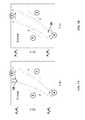
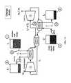
- FIG. 2Ais a schematic flow diagram of working fluid and heat storage media of a pumped thermal system in a charge/heat pump mode.
- FIG. 2Bis a schematic flow diagram of working fluid and heat storage media of a pumped thermal system in a discharge/heat engine mode.
- FIG. 3Ais a schematic pressure and temperature diagram of the working fluid as it undergoes the charge cycle in FIG. 2A .
- FIG. 3Bis a schematic pressure and temperature diagram of the working fluid as it undergoes the discharge cycle in FIG. 2B .
- FIG. 4Ais a schematic perspective view of a closed working fluid system in the pumped thermal system in FIGS. 2A-2B .
- FIG. 4Bis a schematic perspective view of the pumped thermal system in FIGS. 2A-2B with hot side and cold side storage tanks and a closed cycle working fluid system.
- FIG. 5Cshows a heat storage cycle in a pumped thermal system with variable compression ratios between the charge and discharge cycles.
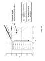
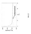
- FIG. 6Ashows roundtrip efficiency contours for a water/salt system.
- the symbols ⁇ andrepresent an approximate range of present large turbomachinery adiabatic efficiency values.
- the dashed arrowsrepresent the direction of increasing efficiency.
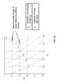
- FIG. 6Bshows roundtrip efficiency contours for a colder storage/salt system.
- FIG. 7Ais a schematic flow diagram of working fluid and heat storage media of a pumped thermal system with a gas-gas heat exchanger for the working fluid in a charge/heat pump mode.
- FIG. 7Bis a schematic flow diagram of working fluid and heat storage media of a pumped thermal system with a gas-gas heat exchanger for the working fluid in a discharge/heat engine mode.
- FIG. 7Cis a schematic flow diagram of working fluid and heat storage media of a pumped thermal system with a gas-gas heat exchanger for the working fluid in a charge/heat pump mode with indirect heat rejection to the environment.
- FIG. 7Dis a schematic flow diagram of working fluid and heat storage media of a pumped thermal system with a gas-gas heat exchanger for the working fluid in a discharge/heat engine mode with indirect heat rejection to the environment.
- FIG. 7Eis a schematic diagram of a piping and valve configuration for the working fluid in the counter-flow thermodynamic charge cycle of FIG. 7C .
- the circular black and white symbolsrepresent three-way or four-way valves. Arrows in pipes represent working fluid flow.
- FIG. 7Fis a schematic diagram of a piping and valve configuration for the working fluid in the counter-flow thermodynamic discharge cycle of FIG. 7D .
- the circular black and white symbolsrepresent three-way or four-way valves. Arrows in pipes represent working fluid flow.
- FIG. 9Ais a schematic flow diagram of cold side recharging in a pumped heat cycle.
- FIG. 9Bis a schematic flow diagram of cold side recharging in a pumped heat cycle with a heat exchanger to ambient.
- FIG. 9Cis a schematic flow diagram of hot side recharging in a pumped heat cycle in solar mode with heating of a solar salt solely by solar power.
- FIG. 9Dis a schematic flow diagram of hot side recharging in a pumped heat cycle in solar mode using a heat exchanger between an intermediate fluid tank and a solar salt.
- FIG. 9Eis a schematic flow diagram of a pumped thermal system charge with a gas-gas heat exchanger in parallel with solar heat input.
- FIG. 9Fis a schematic flow diagram of cold side recharging in a pumped heat cycle with hot side heat rejection to an intermediate fluid circulated in a thermal bath.
- FIG. 9Gis a schematic flow diagram of a pumped thermal system discharge cycle with heat rejection to ambient.
- FIG. 9His a schematic flow diagram of a pumped thermal system discharge cycle with heat rejection to an intermediate fluid circulated in a thermal bath at ambient temperature.
- FIGS. 11A-Dshow (clockwise) cold side recharging in a pumped heat cycle using intercooling with 0, 1, 2 and 3 stages.
- the isothermal compression limitis represented by a horizontal line.
- FIG. 13Ais a schematic diagram of an exemplary piping and valve configuration for achieving the electricity only charge cycle in FIG. 7C .
- the circular black and white symbolsrepresent three-way or four-way valves. Arrows in pipes represent working fluid flow.
- FIG. 13Bis a schematic diagram of an exemplary piping and valve configuration for achieving the electricity only discharge cycle in FIG. 7D .
- the circular black and white symbolsrepresent three-way or four-way valves. Arrows in pipes represent working fluid flow.
- FIG. 13Cis a schematic diagram of an exemplary piping and valve configuration for achieving the cold side recharging refrigeration cycle in FIG. 9F or 9A .
- the circular black and white symbolsrepresent three-way or four-way valves. Arrows in pipes represent working fluid flow.
- FIG. 13Dis a schematic diagram of an exemplary piping and valve configuration for achieving heat engine to ambient cycle in FIG. 9H or 9G with addition of a gas-gas heat exchanger.
- the circular black and white symbolsrepresent three-way or four-way valves. Arrows in pipes represent working fluid flow.
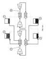
- FIGS. 14A and 14Bare pumped thermal systems with separate compressor/turbine pairs for charge and discharge modes.
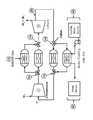
- FIGS. 15A and 15Bshow pumped thermal systems configured in a combustion heat input generation mode.
- FIG. 15Cis a schematic flow diagram of hot side recharging in a pumped heat cycle through heating by a combustion heat source or a waste heat source.
- FIG. 16shows an example of a pumped thermal system with pressure regulated power control.
- FIG. 17shows an example of a pumped thermal system with a pressure encased generator.
- FIG. 18is an example of variable stators in a compressor/turbine pair.
- FIG. 19shows a computer system that is programmed to implement various methods and/or regulate various systems of the present disclosure.
- reversiblegenerally refers to a process or operation that can be reversed via infinitesimal changes in some property of the process or operation without substantial entropy production (e.g., dissipation of energy).
- a reversible processmay be approximated by a process that is at thermodynamic equilibrium.
- the direction of flow of energyis reversible.
- the general direction of operation of a reversible processe.g., the direction of fluid flow
- can be reversedsuch as, e.g., from clockwise to counterclockwise, and vice versa.
- sequencegenerally refers to elements (e.g., unit operations) in order. Such order can refer to process order, such as, for example, the order in which a fluid flows from one element to another.
- a compressor, heat storage unit and turbine in sequenceincludes the compressor upstream of the heat exchange unit, and the heat exchange unit upstream of the turbine.
- a fluidcan flow from the compressor to the heat exchange unit and from the heat exchange unit to the turbine.
- a fluid flowing through unit operations in sequencecan flow through the unit operations sequentially.
- a sequence of elementscan include one or more intervening elements.
- a system comprising a compressor, heat storage unit and turbine in sequencecan include an auxiliary tank between the compressor and the heat storage unit.
- a sequence of elementscan be cyclical.
- the disclosureprovides pumped thermal systems capable of storing electrical energy and/or heat, and releasing energy (e.g., producing electricity) at a later time.
- the pumped thermal systems of the disclosuremay include a heat engine, and a heat pump (or refrigerator).
- the heat enginecan be operated in reverse as a heat pump.
- the heat enginecan be operated in reverse as a refrigerator.
- Any description of heat pump/heat engine systems or refrigerator/heat engine systems capable of reverse operation hereinmay also be applied to systems comprising separate and/or a combination of separate and reverse-operable heat engine system(s), heat pump system(s) and/or refrigerator system(s).
- any description of configurations or operation of heat pumps hereinmay also be applied to configurations or operation of refrigerators, and vice versa.
- Systems of the present disclosurecan operate as heat engines or heat pumps (or refrigerators). In some situations, systems of the disclosure can alternately operate as heat engines and heat pumps. In some examples, a system can operate as a heat engine to generate power, and subsequently operate as a heat pump to store energy, or vice versa. Such systems can alternately and sequentially operate as heat engines as heat pumps. In some cases, such systems reversibly or substantially reversibly operate as heat engines as heat pumps.
- FIG. 1schematically illustrates operating principles of pumped thermal electric storage using a heat pump/heat engine electricity storage system.
- Electricitymay be stored in the form of thermal energy of two materials or media at different temperatures (e.g., thermal energy reservoirs comprising heat storage fluids or thermal storage media) by using a combined heat pump/heat engine system.
- workmay be consumed by the system for transferring heat from a cold material or medium to a hot material or medium, thus lowering the temperature (e.g., sensible energy) of the cold material and increasing the temperature (i.e., sensible energy) of the hot material.
- workmay be produced by the system by transferring heat from the hot material to the cold material, thus lowering the temperature (i.e., sensible energy) of the hot material and increasing the temperature (i.e., sensible energy) of the cold material.
- the systemmay be configured to ensure that the work produced by the system on discharge is a favorable fraction of the energy consumed on charge.
- the systemmay be configured to achieve high roundtrip efficiency, defined herein as the work produced by the system on discharge divided by the work consumed by the system on charge. Further, the system may be configured to achieve the high roundtrip efficiency using components of a desired (e.g., acceptably low) cost.
- Arrows H and W in FIG. 1represent directions of heat flow and work, respectively.
- Heat engines, heat pumps and refrigerators of the disclosuremay involve a working fluid to and from which heat is transferred while undergoing a thermodynamic cycle.
- the heat engines, heat pumps and refrigerators of the disclosuremay operate in a closed cycle. Closed cycles allow, for example, a broader selection of working fluids, operation at elevated cold side pressures, operation at lower cold side temperatures, improved efficiency, and reduced risk of turbine damage.
- One or more aspects of the disclosure described in relation to systems having working fluids undergoing closed cyclesmay also be applied to systems having working fluids undergoing open cycles.
- the heat enginesmay operate on a Brayton cycle and the heat pumps/refrigerators may operate on a reverse Brayton cycle (also known as a gas refrigeration cycle).
- a reverse Brayton cyclealso known as a gas refrigeration cycle.
- thermodynamic cycles that the working fluid may undergo or approximateinclude the Rankine cycle, the ideal vapor-compression refrigeration cycle, the Stirling cycle, the Ericsson cycle or any other cycle advantageously employed in concert with heat exchange with heat storage fluids of the disclosure.
- the working fluidcan undergo a thermodynamic cycle operating at one, two or more pressure levels.
- the working fluidmay operate in a closed cycle between a low pressure limit on a cold side of the system and a high pressure limit on a hot side of the system.
- a low pressure limitof about 10 atmospheres (atm) or greater can be used.
- the low pressure limitmay be at least about 1 atm, at least about 2 atm, at least about 5 atm, at least about 10 atm, at least about 15 atm, at least about 20 atm, at least about 30 atm, at least about 40 atm, at least about 60 atm, at least about 80 atm, at least about 100 atm, at least about 120 atm, at least about 160 atm, or at least about 200 atm, 500 atm, 1000 atm, or more.
- a sub-atmospheric low pressure limitmay be used.
- the low pressure limitmay be less than about 0.1 atm, less than about 0.2 atm, less than about 0.5 atm, or less than about 1 atm.
- the low pressure limitmay be about 1 atmosphere (atm). In the case of a working fluid operating in an open cycle, the low pressure limit may be about 1 atm or equal to ambient pressure.
- the value of the low pressure limitmay be selected based on desired power output and/or power input requirements of the thermodynamic cycle. For example, a pumped thermal system with a low pressure limit of about 10 atm may be able to provide a power output comparable to an industrial gas turbine with ambient (1 atm) air intake. The value of the low pressure limit may also be subject to cost/safety tradeoffs.
- the value of the low pressure limitmay be limited by the value of the high pressure limit, the operating ranges of the hot side and cold side heat storage media (e.g., pressure and temperature ranges over which the heat storage media are stable), pressure ratios and operating conditions (e.g., operating limits, optimal operating conditions, pressure drop) achievable by turbomachinery and/or other system components, or any combination thereof.
- the high pressure limitmay be determined in accordance with these system constraints. In some instances, higher values of the high pressure limit may lead to improved heat transfer between the working fluid and the hot side storage medium.
- Working fluids used in pumped thermal systemsmay include air, argon, other noble gases, carbon dioxide, hydrogen, oxygen, or any combination thereof, and/or other fluids in gaseous, liquid, critical, or supercritical state (e.g., supercritical CO 2 ).
- the working fluidcan be a gas or a low viscosity liquid (e.g., viscosity below about 500 ⁇ 10 ⁇ 6 Poise at 1 atm), satisfying the requirement that the flow be continual.
- a gas with a high specific heat ratiomay be used to achieve higher cycle efficiency than a gas with a low specific heat ratio.
- argone.g., specific heat ratio of about 1.66
- aire.g., specific heat ratio of about 1.4
- the working fluidmay be a blend of one, two, three or more fluids.
- heliumhaving a high thermal conductivity and a high specific heat
- the working fluide.g., argon
- the heat storage mediacan be gases or low viscosity liquids, satisfying the requirement that the flow be continual.
- the systemsmay utilize a first heat storage medium on a hot side of the system (“hot side thermal storage (HTS) medium” or “HTS” herein) and a second heat storage medium on a cold side of the system (“cold side thermal storage (CTS) medium” or “CTS” herein).
- HTShot side thermal storage
- CTScold side thermal storage
- the thermal storage mediae.g., low viscosity liquids
- the thermal storage mediacan have high heat capacities per unit volume (e.g., heat capacities above about 1400 Joule (kilogram Kelvin) ⁇ 1 ) and high thermal conductivities (e.g., thermal conductivities above about 0.7 Watt (meter Kelvin) ⁇ 1 ).
- heat storage mediaalso “heat storage media” herein
- several different thermal storage mediaon either the hot side, cold side or both the hot side and the cold side may be used.
- the operating temperatures of the hot side thermal storage mediumcan be in the liquid range of the hot side thermal storage medium, and the operating temperatures of the cold side thermal storage medium can be in the liquid range of the cold side thermal storage medium.
- liquidsmay enable a more rapid exchange of large amounts of heat by convective counter-flow than solids or gases.
- liquid HTS and CTS mediamay advantageously be used.
- Pumped thermal systems utilizing thermal storage media hereinmay advantageously provide a safe, non-toxic and geography-independent energy (e.g., electricity) storage alternative.
- the hot side thermal storage mediumcan be a molten salt or a mixture of molten salts. Any salt or salt mixture that is liquid over the operating temperature range of the hot side thermal storage medium may be employed.
- Molten saltscan provide numerous advantages as thermal energy storage media, such as low vapor pressure, lack of toxicity, chemical stability, low chemical reactivity with typical steels (e.g., melting point below the creep temperature of steels, low corrosiveness, low capacity to dissolve iron and nickel), and low cost.
- the HTSis a mixture of sodium nitrate and potassium nitrate. In some examples, the HTS is a eutectic mixture of sodium nitrate and potassium nitrate.
- the HTSis a mixture of sodium nitrate and potassium nitrate having a lowered melting point than the individual constituents, an increased boiling point than the individual constituents, or a combination thereof.
- Other examplesinclude potassium nitrate, calcium nitrate, sodium nitrate, sodium nitrite, lithium nitrate, mineral oil, or any combination thereof.
- Further examplesinclude any gaseous (including compressed gases), liquid or solid media (e.g., powdered solids) having suitable (e.g., high) thermal storage capacities and/or capable of achieving suitable (e.g., high) heat transfer rates with the working fluid.
- a mix of 60% sodium nitrate and 40% potassium nitratecan have a heat capacity of approximately 1500 Joule (Kelvin mole) ⁇ 1 and a thermal conductivity of approximately 0.75 Watt (meter Kelvin) ⁇ 1 within a temperature range of interest.
- the hot side thermal storage mediummay be operated in a temperature range that structural steels can handle.
- liquid water at temperatures of about 0° C. to 100° C. (about 273 K-373 K) and a pressure of about 1 atmmay be used as the cold side thermal storage medium. Due to a possible explosion hazard associated with presence of steam at or near the boiling point of water, the operating temperature can be kept below about 100° C. or less while maintaining an operating pressure of 1 atm (i.e., no pressurization). In some cases, the temperature operating range of the cold side thermal storage medium may be extended (e.g., to ⁇ 30° C. to 100° C. at 1 atm) by using a mixture of water and one or more antifreeze compounds (e.g., ethylene glycol, propylene glycol, or glycerol).
- one or more antifreeze compoundse.g., ethylene glycol, propylene glycol, or glycerol
- the cold side thermal storage mediamay comprise hydrocarbons, such as, for example, alkanes (e.g., hexane or heptane), alkenes, alkynes, aldehydes, ketones, carboxylic acids (e.g., HCOOH), ethers, cycloalkanes, aromatic hydrocarbons, alcohols (e.g., butanol), other type(s) of hydrocarbon molecules, or any combinations thereof.
- hydrocarbonssuch as, for example, alkanes (e.g., hexane or heptane), alkenes, alkynes, aldehydes, ketones, carboxylic acids (e.g., HCOOH), ethers, cycloalkanes, aromatic hydrocarbons, alcohols (e.g., butanol), other type(s) of hydrocarbon molecules, or any combinations thereof.
- the cold side thermal storage mediumcan be hexane (e.g., n-hexane). Hexane has a wide liquid range and can remain fluid (i.e., runny) over its entire liquid range ( ⁇ 94° C. to 68° C. at 1 atm). Hexane's low temperature properties are aided by its immiscibility with water. Other liquids, such as, for example, ethanol or methanol can become viscous at the low temperature ends of their liquid ranges due to pre-crystallization of water absorbed from air. In some cases, the cold side thermal storage medium can be heptane (e.g., n-heptane).
- heptanee.g., n-heptane
- Heptanehas a wide liquid range and can remain fluid (i.e., runny) over its entire liquid range ( ⁇ 91° C. to 98° C. at 1 atm). Heptane's low temperature properties are aided by its immiscibility with water. At even lower temperatures, other heat storage media can be used, such as, for example, isohexane (2-methylpentane). In some examples, cryogenic liquids having boiling points below about ⁇ 150° C. (123 K) or about ⁇ 180° C.
- cold side thermal storage mediae.g., propane, butane, pentane, nitrogen, helium, neon, argon and krypton, air, hydrogen, methane, or liquefied natural gas.
- choice of cold side thermal storage mediummay be limited by the choice of working fluid. For example, when a gaseous working fluid is used, a liquid cold side thermal storage medium having a liquid temperature range at least partially or substantially above the boiling point of the working fluid may be required.
- the operating temperature range of CTS and/or HTS mediacan be changed by pressurizing (i.e., raising the pressure) or evacuating (i.e., lowering the pressure) the tanks and thus changing the temperature at which the storage media undergo phase transitions (e.g., going from liquid to solid, or from liquid to gas).
- the hot side and the cold side heat storage fluids of the pumped thermal systemsare in a liquid state over at least a portion of the operating temperature range of the energy storage device.
- the hot side heat storage fluidmay be liquid within a given range of temperatures.
- the cold side heat storage fluidmay be liquid within a given range of temperatures.
- the heat storage fluidsmay be heated, cooled or maintained to achieve a suitable operating temperature prior to, during or after operation.
- Pumped thermal systems of the disclosuremay cycle between charged and discharged modes.
- the pumped thermal systemscan be fully charged, partially charged or partially discharged, or fully discharged.
- cold side heat storagemay be charged (also “recharged” herein) independently from hot side heat storage.
- charging (or some portion thereof) and discharging (or some portion thereof)can occur simultaneously. For example, a first portion of a hot side heat storage may be recharged while a second portion of the hot side heat storage together with a cold side heat storage are being discharged.
- the pumped thermal systemsmay be capable of storing energy for a given amount of time.
- a given amount of energymay be stored for at least about 1 second, at least about 30 seconds, at least about 1 minute, at least about 5 minutes, at least about 30 minutes, at least about 1 hour, at least about 2 hours, at least about 3 hours, at least about 4 hours, at least about 5 hours, at least about 6 hours, at least about 7 hours, at least about 8 hours, at least about 9 hours, at least about 10 hours, at least about 12 hours at least about 14 hours, at least about 16 hours, at least about 18 hours, at least about 20 hours, at least about 22 hours, at least about 24 hours (1 day), at least about 2 days, at least about 4 days, at least about 6 days, at least about 8 days, at least about 10 days, 20 days, 30 days, 60 days, 100 days, 1 year or more.
- Pumped thermal systems of the disclosuremay be capable of storing/receiving input of, and/or extracting/providing output of a substantially large amount of energy and/or power for use with power generation systems (e.g., intermittent power generation systems such as wind power or solar power), power distribution systems (e.g. electrical grid), and/or other loads or uses in grid-scale or stand-alone settings.
- power generation systemse.g., intermittent power generation systems such as wind power or solar power
- power distribution systemse.g. electrical grid
- other loads or uses in grid-scale or stand-alone settingse.g., electrical grid, and/or other loads or uses in grid-scale or stand-alone settings.
- electric power received from an external power sourcee.g., a wind power system, a solar photovoltaic power system, an electrical grid etc.
- a heat pump modei.e., transferring heat from a low temperature reservoir to a high temperature reservoir, thus storing energy.
- the systemcan supply electric power to an external power system or load (e.g., one or more electrical grids connected to one or more loads, a load, such as a factory or a power-intensive process, etc.) by operating in a heat engine mode (i.e., transferring heat from a high temperature reservoir to a low temperature reservoir, thus extracting energy).
- an external power system or loade.g., one or more electrical grids connected to one or more loads, a load, such as a factory or a power-intensive process, etc.
- a heat engine modei.e., transferring heat from a high temperature reservoir to a low temperature reservoir, thus extracting energy.
- the systemmay receive or reject thermal power, including, but not limited to electromagnetic power (e.g., solar radiation) and thermal power (e.g., sensible energy from a medium heated by solar radiation, heat of combustion etc.).
- the pumped thermal systemsare grid-synchronous. Synchronization can be achieved by matching speed and frequency of motors/generators and/or turbomachinery of a system with the frequency of one or more grid networks with which the system exchanges power. For example, a compressor and a turbine can rotate at a given, fixed speed (e.g., 3600 revolutions per minute (rpm)) that is a multiple of grid frequency (e.g., 60 hertz (Hz)). In some cases, such a configuration may eliminate the need for additional power electronics. In some implementations, the turbomachinery and/or the motors/generators are not grid synchronous. In such cases, frequency matching can be accomplished through the use of power electronics.
- rpmrevolutions per minute
- Hzhertz
- the turbomachinery and/or the motors/generatorsare not directly grid synchronous but can be matched through the use of gears and/or a mechanical gearbox.
- the pumped thermal systemsmay also be rampable. Such capabilities may enable these grid-scale energy storage systems to operate as peaking power plants and/or as a load following power plants. In some cases, the systems of the disclosure may be capable of operating as base load power plants.
- each systemcan have a charge and/or discharge power capacity of less than about 1 megawatt (MW), at least about 1 megawatt, at least about 2 MW, at least about 3 MW, at least about 4 MW, at least about 5 MW, at least about 6 MW, at least about 7 MW, at least about 8 MW, at least about 9 MW, at least about 10 MW, at least about 20 MW, at least about 30 MW, at least about 40 MW, at least about 50 MW, at least about 75 MW, at least about 100 MW, at least about 200 MW, at least about 500 MW, at least about 1 gigawatt (GW), at least about 2 GW, at least about 5 GW, at least about 10 GW, at least about 20 GW, at least about 30 GW, at least about 40 GW, at least about 50 GW, at least about 75 GW, at least about 100 GW, or
- a pumped thermal systemcan have a given energy storage capacity.
- a pumped thermal systemis configured as a 100 MW unit operating for 10 hours.
- a pumped thermal systemis configured as a 1 GW plant operating for 12 hours.
- the energy storage capacitycan be less than about 1 megawatt hour (MWh), at least about 1 megawatt hour, at least about 10 MWh, at least about 100 MWh, at least about 1 gigawatt hour (GWh), at least about 5 GWh, at least about 10 GWh, at least about 20 GWh, at least 50 GWh, at least about 100 GWh, at least about 200 GWh, at least about 500 GWh, at least about 700 GWh, at least about 1000 GWh, or more.
- MWhmegawatt hour
- GWhgigawatt hour
- a given power capacitymay be achieved with a given size, configuration and/or operating conditions of the heat engine/heat pump cycle.
- size of turbomachinery, ducts, heat exchangers, or other system componentsmay correspond to a given power capacity.
- a given energy storage capacitymay be achieved with a given size and/or number of hot side thermal storage tanks and/or cold side thermal storage tanks.
- the heat engine/heat pump cyclecan operate at a given power capacity for a given amount of time set by the heat storage capacity of the system or plant.
- the number and/or heat storage capacity of the hot side thermal storage tanksmay be different from the number and/or heat storage capacity of the cold side thermal storage tanks.
- the number of tanksmay depend on the size of individual tanks.
- the size of hot side storage tanksmay differ from the size of cold side thermal storage tanks.
- the hot side thermal storage tanks, the hot side heat exchanger and the hot side thermal storage mediummay be referred to as a hot side heat (thermal) storage unit.
- the cold side thermal storage tanks, the cold side heat exchanger and the cold side thermal storage mediummay be referred to as a cold side heat (thermal) storage unit.
- a pumped thermal storage facilitycan include any suitable number of hot side storage tanks, such as at least about 2, at least about 4, at least about 10, at least about 50, at least about 100, at least about 500, at least about 1,000, at least about 5,000, at least about 10,000, and the like.
- a pumped thermal storage facilityincludes 2, 3, 4, 5, 6, 7, 8, 9, 10, 15, 20, 30, 40, 50, 60, 70, 80, 90, 100, 200, 300, 400, 500, 600, 700, 800, 900, 1,000 or more hot side tanks.
- a pumped thermal storage facilitycan also include any suitable number of cold side storage tanks, such as at least about 2, at least about 4, at least about 10, at least about 50, at least about 100, at least about 500, at least about 1,000, at least about 5,000, at least about 10,000, and the like.
- a pumped thermal storage facilityincludes 2, 3, 4, 5, 6, 7, 8, 9, 10, 15, 20, 30, 40, 50, 60, 70, 80, 90, 100, 200, 300, 400, 500, 600, 700, 800, 900, 1,000 or more cold side tanks.
- An aspect of the disclosurerelates to pumped thermal systems operating on pumped thermal storage cycles.
- the cyclesallow electricity to be stored as heat (e.g., in the form of a temperature differential) and then converted back to electricity through the use of at least two pieces of turbomachinery, a compressor and a turbine.
- the compressorconsumes work and raises the temperature and pressure of a working fluid (WF).
- the turbineproduces work and lowers the temperature and pressure of the working fluid.
- more than one compressor and more than one turbineis used.
- the systemcan include at least 1, at least 2, at least 3, at least 4, or at least 5 compressors.
- the systemcan include at least 1, at least 2, at least 3, at least 4, or at least 5 turbines.
- the compressorsmay be arranged in series or in parallel.
- the turbinesmay be arranged in series or in parallel.
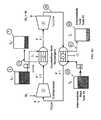
- FIGS. 2A and 2Bare schematic flow diagrams of working fluid and heat storage media of an exemplary pumped thermal system in a charge/heat pump mode and in a discharge/heat engine mode, respectively.
- the systemmay be idealized for simplicity of explanation so that there are no losses (i.e., entropy generation) in either the turbomachinery or heat exchangers.
- the systemcan include a working fluid 20 (e.g., argon gas) flowing in a closed cycle between a compressor 1 , a hot side heat exchanger 2 , a turbine 3 and a cold side heat exchanger 4 .
- a working fluid 20e.g., argon gas
- Fluid flow paths/directions for the working fluid 20e.g., a gas
- a hot side thermal storage (HTS) medium 21e.g., a low viscosity liquid
- a cold side thermal storage (CTS) medium 22e.g., a low viscosity liquid
- FIGS. 3A and 3Bare schematic pressure and temperature diagrams of the working fluid 20 as it undergoes the charge cycles in FIGS. 2A and 2B , respectively, once again simplified in the approximation of no entropy generation. Normalized pressure is shown on the y-axes and temperature is shown on the x-axes. The direction of processes taking place during the cycles is indicated with arrows, and the individual processes taking place in the compressor 1 , the hot side CFX 2 , the turbine 3 and the cold side CFX 4 are indicated on the diagram with their respective numerals.
- the heat exchangers 2 and 4can be configured as counter-flow heat exchangers (CFXs), where the working fluid flows in one direction and the substance it is exchanging heat with is flowing in the opposite direction.
- CFXscounter-flow heat exchangers
- the temperatures of the working fluid and thermal storage medium flipi.e., the counter-flow heat exchanger can have unity effectiveness.
- the counter-flow heat exchangers 2 and 4can be designed and/or operated to reduce entropy generation in the heat exchangers to negligible levels compared to entropy generation associated with other system components and/or processes (e.g., compressor and/or turbine entropy generation).
- the systemmay be operated such that entropy generation in the system is minimized.
- the systemmay be operated such that entropy generation associated with heat storage units is minimized.
- a temperature difference between fluid elements exchanging heatcan be controlled during operation such that entropy generation in hot side and cold side heat storage units is minimized.
- the entropy generated in the hot side and cold side heat storage unitsis negligible when compared to the entropy generated by the compressor, the turbine, or both the compressor and the turbine.
- entropy generation associated with heat transfer in the heat exchangers 2 and 4 and/or entropy generation associated with operation of the hot side storage unit, the cold side storage unit or both the hot side and cold side storage unitscan be less than about 50%, less than about 25%, less than about 20%, less than about 15%, less than about 10%, less than about 5%, less than about 4%, less than about 3%, less than about 2%, or less than about 1% of the total entropy generated within the system (e.g., entropy generated by the compressor 1 , the hot side heat exchanger 2 , the turbine 3 , the cold side heat exchanger 4 and/or other components described herein, such as, for example, a recuperator).
- entropy generationcan be reduced or minimized if the two substances exchanging heat do so at a local temperature differential ⁇ T ⁇ 0 (i.e., when the temperature difference between any two fluid elements that are in close thermal contact in the heat exchanger is small).
- the temperature differential ⁇ T between any two fluid elements that are in close thermal contactmay be less than about 300 Kelvin (K), less than about 200 K, less than about 100 K, less than about 75 K, less than about 50 K, less than about 40 K, less than about 30 K, less than about 20 K, less than about 10 K, less than about 5 K, less than about 3 K, less than about 2 K, or less than about 1 K.
- KKelvin
- entropy generation associated with pressure dropcan be reduced or minimized by suitable design.
- the heat exchange processcan take place at a constant or near-constant pressure.
- a non-negligible pressure dropmay be experienced by the working fluid and/or one or more thermal storage media during passage through a heat exchanger.
- Pressure drop in heat exchangersmay be controlled (e.g., reduced or minimized) through suitable heat exchanger design.
- the pressure drop across each heat exchangermay be less than about 20% of inlet pressure, less than about 10% of inlet pressure, less than about 5% of inlet pressure, less than about 3% of inlet pressure, less than about 2% of inlet pressure, less than about 1% of inlet pressure, less than about 0.5% of inlet pressure, less than about 0.25% of inlet pressure, or less than about 0.1% of inlet pressure.
- the temperature of the working fluidcan either increase (taking heat from the HTS medium 21 , corresponding to the discharge mode in FIGS. 2B and 3B ) or decrease (giving heat to the HTS medium 21 , corresponding to the charge mode in FIGS. 2A and 3A ), depending on the temperature of the HTS medium in the heat exchanger relative the temperature of the working fluid.
- the temperature of the working fluidcan either increase (taking heat from the CTS medium 22 , corresponding to the charge mode in FIGS. 2A and 3A ) or decrease (giving heat to the CTS medium 22 , corresponding to the discharge mode in FIGS. 2B and 3B ), depending on the temperature of the CTS medium in the heat exchanger relative the temperature of the working fluid.
- the heat addition process in the cold side CFX 4can take place over a different range of temperatures than the heat removal process in the hot side CFX 2 .
- the heat rejection process in the cold side CFX 4can take place over a different range of temperatures than the heat addition process in the hot side CFX 2 .
- At least a portion of the temperature ranges of the hot side and cold side heat exchange processesmay overlap during charge, during discharge, or during both charge and discharge.
- the temperatures T 0 , T 1 , T 0 + and T 1 +are so named because T 0 + , T 1 + are the temperatures achieved at the exit of a compressor with a given compression ratio r, adiabatic efficiency ⁇ c and inlet temperatures of T 0 , T 1 respectively.
- the working fluid 20can enter the compressor 1 at position 30 at a pressure P and a temperature T (e.g., at T 1 , P 2 ).
- a pressure P and a temperature Te.g., at T 1 , P 2 .
- work W 1is consumed by the compressor to increase the pressure and temperature of the working fluid (e.g., to T 1 + , P 1 ), as indicated by P ⁇ and T ⁇ at position 31 .
- the temperature T 1 + of the working fluid exiting the compressor and entering the hot side CFX 2 at position 31is higher than the temperature of the HTS medium 21 entering the hot side CFX 2 at position 32 from a second hot side thermal storage tank 7 at a temperature T 0 + (i.e., T 0 + ⁇ T 1 + ).
- T 0 +i.e., T 0 + ⁇ T 1 +
- the working fluid's temperaturedecreases as it moves from position 31 position 34 , giving off heat Q 1 to the HTS medium, while the temperature of the HTS medium in turn increases as it moves from position 32 to position 33 , absorbing heat Q 1 from the working fluid.
- the working fluidexits the hot side CFX 2 at position 34 at the temperature T 0 + and the HTS medium exits the hot side CFX 2 at position 33 into a first hot side thermal storage tank 6 at the temperature T 1 + .
- the heat exchange processcan take place at a constant or near-constant pressure such that the working fluid exits the hot side CFX 2 at position 34 at a lower temperature but same pressure P 1 , as indicated by P and T ⁇ at position 34 .
- the temperature of the HTS medium 21increases in the hot side CFX 2 , while its pressure can remain constant or near-constant.
- the working fluid 20Upon exiting the hot side CFX 2 at position 34 (e.g., at T 0 + , P 1 ), the working fluid 20 undergoes expansion in the turbine 3 before exiting the turbine at position 35 .
- the pressure and temperature of the working fluiddecrease (e.g., to T 0 , P 2 ), as indicated by P ⁇ and T ⁇ at position 35 .
- the magnitude of work W 2 generated by the turbinedepends on the enthalpy of the working fluid entering the turbine and the degree of expansion.
- heatis removed from the working fluid between positions 31 and 34 (in the hot side CFX 2 ) and the working fluid is expanded back to the pressure at which it initially entered the compressor at position 30 (e.g., P 2 ).
- the compression ratio (e.g., P 1 /P 2 ) in the compressor 1being equal to the expansion ratio in the turbine 3 , and the enthalpy of the gas entering the turbine being lower than the enthalpy of the gas exiting the compressor, the work W 2 generated by the turbine 3 is smaller than the work W 1 consumed by the compressor 1 (i.e., W 2 ⁇ W 1 ).
- the temperature T 0 at which the working fluid exits the turbine at position 35is lower than the temperature T 1 at which the working fluid initially entered the compressor at position 30 .
- heat Q 2is added to the working fluid from the CTS medium 22 in the cold side CFX 4 between positions 35 and 30 (i.e., between the turbine 3 and the compressor 1 ).
- the CTS medium 22enters the cold side CFX 4 at position 36 from a first cold side thermal storage tank 8 at the temperature T 1 and exits the cold side CFX 4 at position 37 into a second cold side thermal storage tank 9 at the temperature T 0 , while the working fluid 20 enters the cold side CFX 4 at position 35 at the temperature T 0 and exits the cold side CFX 4 at position 30 at the temperature T 1 .
- the heat exchange processcan take place at a constant or near-constant pressure such that the working fluid exits the cold side CFX 2 at position 30 at a higher temperature but same pressure P 2 , as indicated by P and T ⁇ at position 30 .
- the temperature of the CTS medium 22decreases in the cold side CFX 2 , while its pressure can remain constant or near-constant.
- the heat Q 2is removed from the CTS medium and the heat Q 1 is added to the HTS medium, wherein Q 1 >Q 2 .
- a net amount of work W 1 ⁇ W 2is consumed, since the work W 1 used by the compressor is greater than the work W 2 generated by the turbine.
- a device that consumes work while moving heat from a cold body or thermal storage medium to a hot body or thermal storage mediumis a heat pump; thus, the pumped thermal system in the charge mode operates as a heat pump.
- the discharge mode shown in FIGS. 2B and 3Bcan differ from the charge mode shown in FIGS. 2A and 3A in the temperatures of the thermal storage media being introduced into the heat exchangers.
- the temperature at which the HTS medium enters the hot side CFX 2 at position 32is T 1 + instead of T 0 +
- the temperature of the CTS medium entering the cold side CFX 4 at position 36is T 0 instead of T 1 .
- the working fluidenters the compressor at position 30 at T 0 and P 2 , exits the compressor at position 31 at T 0 + ⁇ T 1 + and P 1 , absorbs heat from the HTS medium in the hot side CFX 2 , enters the turbine 3 at position 34 at T 1 + and P 1 , exits the turbine at position 35 at T 1 >T 0 and P 2 , and finally rejects heat to the CTS medium in the cold side CFX 4 , returning to its initial state at position 30 at T 0 and P 2 .
- the HTS medium at temperature T 1 +can be stored in a first hot side thermal storage tank 6
- the HTS medium at temperature T 0 +can be stored in a second hot side thermal storage tank 7
- the CTS medium at temperature T 1can be stored in a first cold side thermal storage tank 8
- the CTS medium at temperature T 0can be stored in a second cold side thermal storage tank 9 during both charge and discharge modes.
- the inlet temperature of the HTS medium at position 32can be switched between T 1 + and T 0 + by switching between tanks 6 and 7 , respectively.
- the inlet temperature of the CTS medium at position 36can be switched between T 1 and T 0 by switching between tanks 8 and 9 , respectively.
- Switching between tankscan be achieved by including a valve or a system of valves (e.g., valve systems 12 and 13 in FIG. 4B ) for switching connections between the hot side heat exchanger 2 and the hot side tanks 6 and 7 , and/or between the cold side heat exchanger 4 and the cold side tanks 8 and 9 as needed for the charge and discharge modes.
- connectionsmay be switched on the working fluid side instead, while the connections of storage tanks 6 , 7 , 8 and 9 to the heat exchangers 2 and 4 remain static.
- flow paths and connections to the heat exchangersmay depend on the design (e.g., shell-and-tube) of each heat exchanger.
- one or more valvescan be used to switch the direction of both the working fluid and the heat storage medium through the counter-flow heat exchanger on charge and discharge. Such configurations may be used, for example, due to high thermal storage capacities of the heat exchanger component, to decrease or eliminate temperature transients, or a combination thereof.
- one or more valvescan be used to switch the direction of only the working fluid, while the direction of the HTS or CTS can be changed by changing the direction of pumping, thereby maintaining the counter-flow configuration.
- different valve configurationsmay be used for the HTS and the CTS. Further, any combination of the valve configurations herein may be used. For example, the system may be configured to operate using different valve configurations in different situations (e.g., depending on system operating conditions).
- the working fluid 20can enter the compressor 1 at position 30 at a pressure P and a temperature T (e.g., at T 0 , P 2 ).
- a pressure P and a temperature Te.g., at T 0 , P 2 .
- work W 1is consumed by the compressor to increase the pressure and temperature of the working fluid (e.g., to T 0 + , P 1 ), as indicated by P ⁇ and T ⁇ at position 31 .
- the temperature T 0 + of the working fluid exiting the compressor and entering the hot side CFX 2 at position 31is lower than the temperature of the HTS medium 21 entering the hot side CFX 2 at position 32 from a first hot side thermal storage tank 6 at a temperature T 1 + (i.e., T 0 + ⁇ T 1 + ).
- T 1 +i.e., T 0 + ⁇ T 1 +
- the working fluid's temperatureincreases as it moves from position 31 position 34 , absorbing heat Q 1 from the HTS medium, while the temperature of the HTS medium in turn decreases as it moves from position 32 to position 33 , giving off heat Q 1 to the working fluid.
- the working fluidexits the hot side CFX 2 at position 34 at the temperature T 1 + and the HTS medium exits the hot side CFX 2 at position 33 into the second hot side thermal storage tank 7 at the temperature T 0 + .
- the heat exchange processcan take place at a constant or near-constant pressure such that the working fluid exits the hot side CFX 2 at position 34 at a higher temperature but same pressure P 1 , as indicated by P and T ⁇ at position 34 .
- the temperature of the HTS medium 21decreases in the hot side CFX 2 , while its pressure can remain constant or near-constant.
- the working fluid 20Upon exiting the hot side CFX 2 at position 34 (e.g., at T 1 + , P 1 ), the working fluid 20 undergoes expansion in the turbine 3 before exiting the turbine at position 35 .
- the pressure and temperature of the working fluiddecrease (e.g., to T 1 , P 2 ), as indicated by P ⁇ and T ⁇ at position 35 .
- the magnitude of work W 2 generated by the turbinedepends on the enthalpy of the working fluid entering the turbine and the degree of expansion.
- heatis added to the working fluid between positions 31 and 34 (in the hot side CFX 2 ) and the working fluid is expanded back to the pressure at which it initially entered the compressor at position 30 (e.g., P 2 ).
- the compression ratio (e.g., P 1 /P 2 ) in the compressor 1being equal to the expansion ratio in the turbine 3 , and the enthalpy of the gas entering the turbine being higher than the enthalpy of the gas exiting the compressor, the work W 2 generated by the turbine 3 is greater than the work W 1 consumed by the compressor 1 (i.e., W 2 >W 1 ).
- the temperature T 1 at which the working fluid exits the turbine at position 35is higher than the temperature T 0 at which the working fluid initially entered the compressor at position 30 .
- heat Q 2is rejected by the working fluid to the CTS medium 22 in the cold side CFX 4 between positions 35 and 30 (i.e., between the turbine 3 and the compressor 1 ).
- the CTS medium 22enters the cold side CFX 4 at position 36 from a second cold side thermal storage tank 9 at the temperature T 0 and exits the cold side CFX 4 at position 37 into a first cold side thermal storage tank 8 at the temperature T 1 , while the working fluid 20 enters the cold side CFX 4 at position 35 at the temperature T 1 and exits the cold side CFX 4 at position 30 at the temperature T 0 .
- the heat exchange processcan take place at a constant or near-constant pressure such that the working fluid exits the cold side CFX 2 at position 30 at a higher temperature but same pressure P 2 , as indicated by P and T ⁇ at position 30 .
- the temperature of the CTS medium 22increases in the cold side CFX 2 , while its pressure can remain constant or near-constant.
- the heat Q 2is added to the CTS medium and the heat Q 1 is removed from the HTS medium, wherein Q 1 >Q 2 .
- a net amount of work W 2 ⁇ W 1is generated, since the work W 1 used by the compressor is smaller than the work W 2 generated by the turbine.
- a device that generates work while moving heat from a hot body or thermal storage medium to a cold body or thermal storage mediumis a heat engine; thus, the pumped thermal system in the discharge mode operates as a heat engine.
- FIG. 4Ais a simplified schematic perspective view of a closed working fluid system in the pumped thermal system in FIGS. 2A-2B .
- the working fluid 20(contained inside tubing) circulates clockwise between the compressor 1 , the hot side heat exchanger 2 , the turbine 3 , and the cold side heat exchanger 4 .
- the compressor 1 and the turbine 3can be ganged on a common mechanical shaft 10 such that they rotate together.
- the compressor 1 and the turbine 3can have separate mechanical shafts.
- a motor/generator 11e.g., including a synchronous motor-synchronous generator converter on a single common shaft) provides power to and from the turbomachinery.
- the compressor, the turbine and the motor/generatorare all located on a common shaft.
- Pipes at positions 32 and 33transfer hot side thermal storage fluid to and from the hot side heat exchanger 2 , respectively.
- Pipes at positions 36 and 37transfer cold side thermal storage fluid to and from the cold side heat exchanger 4 , respectively.
- the system of FIG. 4Ais illustrated as comprising a compressor 1 and turbine 3
- the systemcan include one or more compressors and one or more turbines, which may operate, for example, in a parallel configuration, or alternatively in a series configuration or in a combination of parallel and series configurations.
- a system of compressors or turbinesmay be assembled such that a given compression ratio is achieved.
- different compression ratiose.g., on charge and discharge
- the working fluidis directed to a plurality of compressors and/or a plurality of turbines.
- the compressor and/or turbinemay have temperature dependent compression ratios. Arrangement and/or operation of the turbomachinery and/or other elements of the system may be adjusted in accordance with the temperature dependence (e.g., to optimize performance).
- FIG. 4Bis a simplified schematic perspective view of the pumped thermal system in FIGS. 2A-2B with hot side and cold side storage tanks and a closed cycle working fluid system.
- the HTS mediumis a molten salt and the CTS medium is a low temperature liquid.
- One, two or more first hot side tanks 6 (at the temperature T 1 + ) and one, two or more second hot side tanks 7 (at the temperature T 0 + ), both for holding the HTS medium,are in fluid communication with a valve 13 configured to transfer the HTS medium to and from the hot side heat exchanger 2 .
- One, two or more first cold side tanks 8 (at the temperature T 1 ) and one, two or more second cold side tanks 9 (at the temperature T 0 ), both for holding the CTS medium,are in fluid communication with a valve 12 configured to transfer the CTS medium to and from the cold side heat exchanger 4 .
- the thermal energy reservoirs or storage tanksmay be thermally insulated tanks that can hold a suitable quantity of the relevant thermal storage medium (e.g., heat storage fluid).
- the storage tanksmay allow for relatively compact storage of large amounts of thermal energy.
- the hot side tanks 6 and/or 7can have a diameter of about 80 meters, while the cold side tanks 8 and/or 9 can have a diameter of about 60 meters.
- the size of each (i.e., hot side or cold side) thermal storage for a 1 GW plant operating for 12 hourscan be about 20 medium-sized oil refinery tanks.
- a third set of tanks containing storage media at intermediate temperatures between the other tanksmay be included on the hot side and/or the cold side.
- a third storage or transfer tank (or set of tanks) at a temperature intermediate to the temperatures of a first tank (or set of tanks) and a second tank (or set of tanks)may be provided.
- a set of valvesmay be provided for switching the storage media between the different tanks and heat exchangers.
- thermal mediamay be directed to different sets of tanks after exiting the heat exchangers depending on operating conditions and/or cycle being used.
- one or more additional sets of storage tanks at different temperaturesmay be added on the hot side and/or the cold side.
- the storage tanksmay operate at ambient pressure.
- thermal energy storage at ambient pressurecan provide safety benefits.
- the storage tanksmay operate at elevated pressures, such as, for example, at a pressure of at least about 2 atm, at least about 5 atm, at least about 10 atm, at least about 20 atm, or more.
- the storage tanksmay operate at reduced pressures, such as, for example, at a pressure of at most about 0.9 atm, at most about 0.7 atm, at most about 0.5 atm, at most about 0.3 atm, at most about 0.1 atm, at most about 0.01 atm, at most about 0.001 atm, or less.
- the storage tankscan be sealed from the surrounding atmosphere.
- the storage tanksmay not be sealed.
- the tanksmay include one or more pressure regulation or relief systems (e.g., a valve for safety or system optimization).
- the first hot side tank(s) 6(at the temperature T 1 + ) can contain HTS medium at a higher temperature than the second hot side tank(s) 7 (at the temperature T 0 + ), and the first cold side tank(s) 8 (at the temperature T 1 ) can contain CTS medium at a higher temperature than the second cold side tank(s) 9 (at the temperature T 0 ).
- HTS medium in the first (higher temperature) hot side tank(s) 6 and/or CTS medium in the second (lower temperature) cold side tank(s) 9can be replenished.
- HTS medium in the first (higher temperature) hot side tank(s) 6 and/or CTS medium in the second (lower temperature) cold side tank(s) 9can be consumed.
- two of the four storage tanks 6 , 7 , 8 and 9are feeding thermal storage medium to the heat exchangers 2 and 4 at the inlets 32 and 36 , respectively, and the other two tanks are receiving thermal storage medium from the heat exchangers 2 and 4 from the exits 33 and 37 , respectively.
- the feed tankscan contain a storage medium at a given temperature due to prior operating conditions, while the receiving tanks' temperatures can depend on current system operation (e.g., operating parameters, loads and/or power input).
- the receiving tank temperaturesmay be set by the Brayton cycle conditions.
- the receiving tank temperaturesmay deviate from desired values due to deviations from predetermined cycle conditions (e.g., variation of absolute pressure in response to system demand) and/or due to entropy generation within the system. In some cases (e.g., due to entropy generation), at least one of the four tank temperatures can be higher than desired.
- a radiatorcan be used to reject or dissipate this waste heat to the environment. In some cases, heat rejection to the environment may be enhanced (e.g., using evaporative cooling etc.).
- the waste heat generated during operation of the pumped thermal systems hereincan also be utilized for other purposes. For example, waste heat from one part of the system may be used elsewhere in the system. In another example, waste heat may be provided to an external process or system, such as, for example, a manufacturing process requiring low grade heat, commercial or residential heating, thermal desalination, commercial drying operations etc.
- Components of pumped thermal systems of the disclosuremay exhibit non-ideal performance, leading to losses and/or inefficiencies.
- the major losses in the systemmay occur due to inefficiencies of the turbomachinery (e.g., compressor and turbine) and the heat exchangers.
- the losses due to the heat exchangersmay be small compared to the losses due to the turbomachinery.
- the losses due to the heat exchangerscan be reduced to near zero with suitable design and expense. Therefore, in some analytical examples, losses due to the heat exchangers and other possible small losses due to pumps, the motor/generator and/or other factors may be neglected.
- Losses due to turbomachinerycan be quantified in terms of adiabatic efficiencies ⁇ c and ⁇ t (also known as isentropic efficiencies) for compressors and turbines, respectively.
- ⁇ c and ⁇ talso known as isentropic efficiencies
- the actual amount of work produced or consumed by a cyclecan then be expressed as
- ⁇r ⁇ - 1 ⁇
- rthe compression ratio (i.e., ratio of the higher pressure to the lower pressure)
- pumped thermal cycles of the disclosurecan follow identical paths in both charge and discharge cycles (e.g., as shown in FIGS. 3A and 3B ).
- pumped thermal cycles of the disclosurecan follow identical paths in both charge and discharge cycles (e.g., as shown in FIGS. 3A and 3B ).
- ⁇ c ⁇ 1 and/or ⁇ t ⁇ 1compression in the compressor can lead to a greater temperature increase than in the ideal case for the same compression ratio, and expansion in the turbine can lead to a smaller temperature decrease than in the ideal case.
- the polytropic efficiency of the compressor ⁇ cpmay be at least about 0.3, at least about 0.5, at least about 0.6, at least about 0.7, at least about 0.75, at least about 0.8, at least about 0.85, at least about 0.9, at least about 0.91, at least about 0.92, at least about 0.93, at least about 0.96, or more.
- the polytropic efficiency of the compressor ⁇ tpmay be at least about 0.3, at least about 0.5, at least about 0.6, at least about 0.7, at least about 0.75, at least about 0.8, at least about 0.85, at least about 0.9, at least about 0.91, at least about 0.92, at least about 0.93, at least about 0.96, at least about 0.97 or more.
- T 0 + , T 1 +were previously defined as the temperatures achieved at the exit of a compressor with a given compression ratio r, adiabatic efficiency ⁇ c and inlet temperatures of T 0 , T 1 respectively. In some examples, these four temperatures are related by the equation
- CTSwater
- HTSmolten salt
- the CTS medium on the cold sideis water
- the HTS medium on the hot sideis molten salt.
- the systemcan include 4 heat storage tanks.
- the working fluid at T 0 and P 2can exchange heat with a CTS medium in the cold side heat exchanger 4 , whereby its temperature can increase to T 1 (assuming negligible pressure drop, its pressure can remain P 2 ).
- the temperature and pressure of the working fluidcan increase from T 1 , P 2 to T 1 + , P 1 .
- the temperaturesare related by the relation
- T ⁇ 0 + T 0⁇ ⁇ tp .
- ⁇ tilde over (T) ⁇ 0 +is the temperature at which the working fluid enters the inlet of a turbine with adiabatic efficiency ⁇ t and compression ratio r in order to exit at the temperature T 0 .
- the temperature ⁇ tilde over (T) ⁇ 0 +may be incorporated into charge cycles of the disclosure by first heat exchanging the working fluid with the HTS medium from T 1 + to T 0 + , followed by further cooling the working fluid from ⁇ tilde over (T) ⁇ 0 + to ⁇ tilde over (T) ⁇ 0 + as illustrated by section 38 of the cycle in FIG. 5A .
- the working fluid at T 1 and P 2can exchange heat with a CTS medium in the cold side heat exchanger 4 , whereby its temperature can decrease to T 0 (assuming negligible pressure drop, its pressure can remain P 2 ).
- the working fluidcan then exchange heat with an HTS medium in the hot side heat exchanger 2 , such that its temperature can increase (at constant pressure P 1 , assuming negligible pressure drop).
- ⁇ tilde over (T) ⁇ 1is the temperature at which the working fluid exits the outlet of a turbine with adiabatic efficiency ⁇ t and compression ratio r after entering the inlet of the turbine at the temperature T 1 + .
- the temperature ⁇ tilde over (T) ⁇ 1may be incorporated into the discharge cycles of the disclosure by first cooling the working fluid exiting the turbine at ⁇ tilde over (T) ⁇ 1 to T 1 , as illustrated by section 39 of the cycle in FIG. 5B , followed by heat exchanging the working fluid with the CTS medium form T 1 to T 0 .
- the charge and discharge cyclesmay be closed by additional heat rejection operations in sections 38 (between T 0 + and ⁇ tilde over (T) ⁇ 0 + ) and 39 (between ⁇ tilde over (T) ⁇ 1 and T 1 ), respectively.
- closing the cycles through heat rejection in sections of the cycles where the working fluid can reject heat to ambient at low costmay eliminate the need for additional heat input into the system.
- the sections of the cycles where the working fluid can reject heat to ambientmay be limited to sections where the temperature of the working fluid is high enough above ambient temperature for ambient cooling to be feasible.
- heatmay be rejected to the environment in sections 38 and/or 39 .
- heatmay be rejected using one or more working fluid to air radiators, intermediate water cooling, or a number of other methods.
- heat rejected in sections 38 and/or 39may be used for another useful purpose, such as, for example, cogeneration, thermal desalination and/or other examples described herein.
- the cyclesmay be closed by varying the compression ratios between the charge and discharge cycles, as shown, for example, in FIG. 5C .
- the ability to vary compression ratio on charge and dischargemay be implemented, for example, by varying the rotation speed of the compressor and/or turbine, by variable stator pressure control, by bypassing a subset of the compression or expansion stages on charge or discharge by the use of valves, or by using dedicated compressor/turbine pairs for charge and discharge mode.
- the compression ratio in the discharge cycle in FIG. 5Bcan be changed such that heat rejection in section is 39 is not used, and only heat rejection in section 38 in the charge cycle is used. Varying the compression ratio may allow heat (i.e., entropy) to be rejected at a lower temperature, thereby increasing overall roundtrip efficiency.
- the compression ratio on charge, r ccan be set such that
- T 1 + T 1⁇ D ⁇ tp .
- the upper temperatures T 1 + and T 1can be identical on charge and discharge and no heat removal may be needed in this portion (also “leg” herein) of the cycle.
- T 0 +(d)T 0 ⁇ D 1/ ⁇ cp
- a heat rejection devicee.g., devices 55 and 56 shown in FIG. 7D
- a heat rejection devicecan be used to lower the temperature of the CTS from T 0 +(d) to T 0 +(c) between discharge and charge.
- FIG. 5Cshows an example of a cycle with variable compression ratios.
- the compression ratiocan be higher on discharge (when work is produced by the system) than on charge (when work is consumed by the system), which may increase an overall round trip efficiency of the system.
- a lower compression ratio of ⁇ 3can be used;
- a compression ratio of >3can be used.
- the upper temperatures reached in both cycles 80 and 81can be T 1 and T 1 + , and no excess heat may be rejected.
- the compression ratiomay be varied between charge and discharge such that the heat dissipation to the environment needed for closing the cycle on both charge and discharge occurs between the temperatures T 0 +(C) (the temperature of the working fluid before it enters the turbine during the charge cycle) and T 0 +(D) (the temperature of the working fluid as it exits the compressor on discharge) and not above the temperature T 1 (the temperature of the working fluid before it enters the compressor on charge and/or exits the turbine on discharge). In some examples, none of the heat is rejected at a temperature above the lowest temperature of the HTS medium.
- a given amount of heat Q Hcan be transferred using a given quantity of work W in heat pump (charge) mode, and the same Q H can be used in heat engine (discharge) mode to produce the same work W, leading to a unity (i.e., 100%) roundtrip efficiency.
- chargeheat pump
- dischargeheat engine
- roundtrip efficiencies of pumped thermal systemsmay be limited by how much the components deviate from ideal performance.
- the roundtrip efficiencycan be derived by considering the net work output during the discharge cycle,
- Roundtrip efficienciesmay be calculated for different configurations of pumped thermal systems (e.g., for different classes of thermal storage media) based on turbomachinery component efficiencies, ⁇ c and ⁇ t .
- Exemplary roundtrip efficiency contours at values of ⁇ store of 10%, 20%, 30%, 40%, 50%, 60%, 70%, 80% and 90%are shown as a function of component efficiencies ⁇ c and ⁇ t on the x- and y-axes, respectively.
- the symbols ⁇represent the approximate range of present large turbomachinery adiabatic efficiency values.
- the dashed arrowsrepresent the direction of increasing efficiency.
- Exemplary roundtrip efficiency contours at values of ⁇ store of 10%, 20%, 30%, 40%, 50%, 60%, 70%, 80% and 90%are shown as a function of component efficiencies ⁇ c and ⁇ t on the x- and y-axes, respectively.
- the symbols ⁇and represent the approximate range of present large turbomachinery adiabatic efficiency values.
- using hexane, heptane and/or another CTS medium capable of low temperature operationmay result in significant improvements of system efficiency.
- regeneration and recuperationcan be used interchangeably, although they may have different meanings.
- the terms “recuperation” and “recuperator”generally refer to the presence of one or more additional heat exchangers where the working fluid exchanges heat with itself during different segments of a thermodynamic cycle through continuous heat exchange without intermediate thermal storage.
- the terms “regeneration” and “regenerator”may be used to describe the same configuration as the terms “recuperation” and “recuperator.”
- the roundtrip efficiency of pumped thermal systemsmay be substantially improved if the allowable temperature ranges of the storage materials can be extended.
- thismay be accomplished by choosing a material or medium on the cold side that can go to temperatures below 273 K (0° C.).
- a CTS mediume.g., hexane
- T 0 +i.e., the lowest temperature of the working fluid in the hot side heat exchanger
- some (e.g., modest) compression ratiosmay be below the freezing point of the molten salt, making the molten salt unviable as the HTS medium.
- thiscan be resolved by including a working fluid to working fluid (e.g., gas-gas) heat exchanger (also “recuperator” or “regenerator” herein) in the cycle.
- FIG. 7Ais a schematic flow diagram of working fluid and heat storage media of a pumped thermal system in a charge/heat pump mode with a gas-gas heat exchanger 5 for the working fluid.
- the use of the gas-gas heat exchangercan enable use of colder heat storage medium on the cold side of the system.
- the working fluidcan be argon.
- the working fluidcan be a mixture of primarily argon mixed with another gas such as helium.
- the working fluidmay comprise at least about 50% argon, at least about 60% argon, at least about 70% argon, at least about 80% argon, at least about 90% argon, or about 100% argon, with balance helium.
- the CTS mediumcan be hexane or heptane and the HTS medium can be molten salt.
- the systemcan include four heat storage tanks.
- the working fluidenters the compressor at T 1 and P 2 , exits the compressor at T 1 + and P 1 , rejects heat Q 1 to the HTS medium 21 in the hot side CFX 2 , exiting the hot side CFX 2 at T 1 and P 1 , rejects heat Q recup (also “Q regen ” herein, as shown, for example, in the accompanying drawings) to the cold (low pressure) side working fluid in the heat exchanger or recuperator 5 , exits the recuperator 5 at T 0 + and P 1 , rejects heat to the environment (or other heat sink) in section 38 (e.g., a radiator), enters the turbine 3 at ⁇ tilde over (T) ⁇ 0 + and P 1 , exits the turbine at T 0 and P 2 , absorbs heat Q 2 from the CTS medium 22 in the cold side CFX 4 , exiting the cold side CFX 4 at T 0 + and P 2 , absorbs heat
- FIG. 7Bis a schematic flow diagram of working fluid and heat storage media of the pumped thermal system in FIG. 7A in a discharge/heat engine mode.
- the use of the gas-gas heat exchangercan enable use of colder heat storage fluid (CTS) and/or colder working fluid on the cold side of the system.
- CTScolder heat storage fluid
- a cold side storage mediume.g., liquid hexane
- the CTS mediumcan be hexane or heptane
- the HTS mediumcan be molten salt
- the systemmay include 4 heat storage tanks.
- the working fluidenters the compressor at T 0 and P 2 , exits the compressor at T 0 + and P 1 , absorbs heat Q recup from the cold (low pressure) side working fluid in the heat exchanger or recuperator 5 , exits the recuperator 5 at T 1 and P 1 , absorbs heat Q 1 from the HTS medium 21 in the hot side CFX 2 , exiting the hot side CFX 2 at T 1 + and P 1 , enters the turbine 3 at T 1 + and P 1 , exits the turbine at ⁇ tilde over (T) ⁇ 1 and P 2 , rejects heat to the environment (or other heat sink) in section 39 (e.g., a radiator), rejects heat Q recup to the hot (high pressure) side working fluid in the heat exchanger or recuperator 5 , enters the cold side CFX 4 at T 0 + and P 2 , rejects heat Q 2 to the CTS medium 22 in the cold side CFX 4 , and finally
- the charge cycleremains the same as in FIGS. 7A and 8A , except that the working fluid exits the recuperator 5 at ⁇ tilde over (T) ⁇ 0 + and P 1 (instead of at T 0 + and P 1 as in FIGS. 7A and 8A ), enters the turbine 3 at ⁇ tilde over (T) ⁇ 0 + and P 1 , exits the turbine at T 0 and P 2 , absorbs heat Q 2 from the CTS medium 22 having a temperature ⁇ tilde over (T) ⁇ 0 + (instead of at T 0 + as in FIGS.
- the discharge cycleremains the same as in FIGS. 7B and 8B , except that the temperature of the HTS medium being deposited in tank 7 is changed.
- the working fluidexits the recuperator 5 at ⁇ tilde over (T) ⁇ 1 and P 1 (instead of at T 1 and P 1 as in FIGS. 7B and 8B ) and absorbs heat Q 1 from the HTS medium 21 in the hot side CFX 2 .
- the HTS mediumexits the hot side CFX 2 having a temperature ⁇ tilde over (T) ⁇ 1 (instead of at T 1 as in FIGS. 7B and 8B ).
- the working fluidthen exits the hot side CFX 2 at T 1 + and P 1 , enters the turbine 3 at T 1 + and P 1 , and exits the turbine at ⁇ tilde over (T) ⁇ 1 and P 2 before reentering the recuperator 5 .
- the heat between temperatures ⁇ tilde over (T) ⁇ 1 and T 1is no longer rejected from the working fluid to the environment directly (as in section 39 in FIGS. 7B and 8B ).
- the CTS mediumenters the tank 8 at temperature T 0 + .
- heat exchange with ambientmay be used to cool the HTS medium 21 from the temperature ⁇ tilde over (T) ⁇ 1 used in the discharge cycle to the temperature T 1 used in the charge cycle.
- heat exchange with ambientmay be used to cool the CTS medium 22 from the temperature T 0 + used in the discharge cycle to the temperature ⁇ tilde over (T) ⁇ 0 + used in the charge cycle.
- the hot side and cold side storage mediamay be cooled at an arbitrarily slow rate (e.g., by radiating away or by other means of giving off the heat to the environment).
- heatcan be rejected from the CTS medium to the environment by circulating the CTS medium in the tank 8 in a heat rejection device 55 that can absorb heat from the CTS medium and reject heat to the environment until the CTS medium cools from the temperature T 0 + to the temperature ⁇ tilde over (T) ⁇ 0 + .
- the heat rejection device 55can be, for example, a radiator, a thermal bath containing a substance such as water or salt water, or a device immersed in a natural body of water such as a lake, river or ocean.
- the heat rejection device 55can also be an air cooling apparatus, or a series of pipes which are thermally connected to a solid reservoir (e.g., pipes embedded in the ground).
- heatcan be rejected from the HTS medium to the environment by circulating the HTS in the tank 7 in a heat rejection device 56 that can absorb heat from the HTS medium and reject heat to the environment until the HTS medium cools from the temperature ⁇ tilde over (T) ⁇ 1 to the temperature T 1 .
- the heat rejection device 56can be, for example, a radiator, a thermal bath containing a substance such as water or salt water, or a device immersed in a natural body of water such as a lake, river or ocean.
- the heat rejection device 56can also be an air cooling apparatus or a series of pipes which are thermally connected to a solid reservoir (e.g., pipes embedded in the ground).
- rejecting heat to ambient through the use of the thermal storage mediamay be used in conjunction with the variable compression ratio charge and/or discharge cycles described, for example, in FIG. 5C .
- this systemonly the CTS medium may exchange heat with ambient.
- Such a systemcan also be implemented with a recuperator to extend the temperature ranges of the HTS and CTS media in the cycles.
- three separate cold side storage tanks at respective temperatures T 0 , ⁇ tilde over (T) ⁇ 0 + and T 0 +may be used (e.g., an extra tank may be used in addition to the tanks 8 and 9 ).
- heat from the working fluid exiting the recuperator 5may be transferred to the CTS medium in the T 0 + -tank.
- the CTS mediummay be cooled in/by, for example, the heat rejection device 55 prior to entering the ⁇ tilde over (T) ⁇ 0 + -tank.
- three separate hot side storage tanks at respective temperatures T 1 , ⁇ tilde over (T) ⁇ 1 and T 1 +may be used (e.g., an extra tank may be used in addition to the tanks 6 and 7 ).
- heat from the working fluid exiting the recuperator 5may be transferred to the HTS medium in the ⁇ tilde over (T) ⁇ 1 -tank.
- the HTS mediummay be cooled in/by, for example, the heat rejection device 56 prior to entering the T 1 -tank. Heat rejection to the environment in such a manner may present several advantages.
- the HTS and CTS mediamay instead reject heat over extended time periods, thus reducing the cost of the cooling infrastructure.
- itmay allow the decision regarding when heat is rejected to the environment to be delayed such that heat exchange to ambient may be performed when temperature (e.g., the ambient temperature) is most favorable.
- heat rejection on the hot side (high pressure) side of the closed charge cyclecan take place in three operations (heat exchange with the HTS medium, followed by recuperation, followed by heat rejection to the environment), and heat rejection on the cold side (low pressure) side of the closed discharge cycle can take place in three operations (heat rejection to the environment, followed by recuperation, followed by heat exchange with the CTS medium).
- the higher temperature HTS tank(s) 6can remain at T 1 + while the lower temperature HTS tank(s) 7 can now be at the temperature T 1 >T 0 + , and the lower temperature CTS tank(s) 9 can remain at T 0 while the higher temperature CTS tank(s) 8 can now be at the temperature T 0 + ⁇ T 1 .
- recuperationmay be implemented using the heat exchanger 5 for direct transfer of heat between the working fluid on the high pressure side and the working fluid on the low pressure side.
- an additional pair (or plurality) of heat exchangers together with an additional heat transfer medium or fluide.g., a dedicated thermal heat transfer fluid that is liquid in an appropriate temperature range, such as, for example, therminol
- an additional heat exchangermay be added in series with the cold side heat exchanger and an additional heat exchanger may be added in series with the hot side heat exchanger.
- the additional heat transfer mediummay circulate between the two additional heat exchangers in a closed loop.
- one or more additional heat exchangersmay be placed elsewhere in the system to facilitate recuperation. Further, one or more additional heat transfer media or mixtures thereof may be used. The one or more additional heat transfer media fluids may be in fluid or thermal communication with one or more other components, such as, for example, a cooling tower or a radiator.
- hexane or heptanecan be used as a CTS medium
- nitrate saltcan be used as an HTS medium.
- the operating temperatures of the pumped thermal storage cyclesmay be limited by the melting point of hexane (178 K or ⁇ 95° C.) at T 0 and by the melting point of the nitrate (494 K or 221° C.) at T 1 .
- the operating temperaturesmay be limited by the boiling point of hexane (341 K or 68° C.) at T 0 + and by the decomposition of nitrate (873 K or 600° C.) at T 1 + .
- the high pressure and low pressure temperature rangescan overlap such that recuperation can be implemented.
- the actual temperatures T 0 , T 1 , T 0 + and T 1 + and pressure ratios implemented in hexane/nitrate systemsmay differ from the limits above.
- recuperationmay enable the compression ratio to be reduced.
- reducing the compression ratiomay result in reduced compressor and turbine losses.
- the compression ratiomay be at least about 1.2, at least about 1.5, at least about 2, at least about 2.5, at least about 3, at least about 3.5, at least about 4, at least about 4.5, at least about 5, at least about 6, at least about 8, at least about 10, at least about 15, at least about 20, at least about 30, or more.
- T 0may be at least about 30 K, at least about 50 K, at least about 80 K, at least about 100 K, at least about 120 K, at least about 140 K, at least about 160 K, at least about 180 K, at least about 200 K, at least about 220 K, at least about 240 K, at least about 260 K, or at least about 280 K.
- T 0 +may be at least about 220 K, at least about 240 K, at least about 260 K, at least about 280 K, at least about 300 K, at least about 320 K, at least about 340 K, at least about 360 K, at least about 380 K, at least about 400 K, or more.
- the temperatures T 0 and T 0 +can be constrained by the ability to reject excess heat to the environment at ambient temperature. In some cases. the temperatures T 0 and T 0 + can be constrained by the operating temperatures of the CTS (e.g., a phase transition temperature). In some cases, the temperatures T 0 and T 0 + can be constrained by the compression ratio being used. Any description of the temperatures T 0 and/or T 0 + herein may apply to any system or method of the disclosure.
- T 1may be at least about 350K, at least about 400 K, at least about 440 K, at least about 480 K, at least about 520 K, at least about 560 K, at least about 600 K, at least about 640 K, at least about 680 K, at least about 720 K, at least about 760 K, at least about 800 K, at least about 840 K, at least about 880 K, at least about 920 K, at least about 960 K, at least about 1000 K, at least about 1100 K, at least about 1200 K, at least about 1300 K, at least about 1400 K, or more.
- T 1 +may be at least about 480 K, at least about 520 K, at least about 560 K, at least about 600 K, at least about 640 K, at least about 680 K, at least about 720 K, at least about 760 K, at least about 800 K, at least about 840 K, at least about 880 K, at least about 920 K, at least about 960 K, at least about 1000 K, at least about 1100 K, at least about 1200 K, at least about 1300 K, at least about 1400 K, at least about 1500 K, at least about 1600 K, at least about 1700 K, or more.
- the temperatures T 1 and T 1 +can be constrained by the operating temperatures of the HTS. In some cases.
- the temperatures T 1 and T 1 +can be constrained by the thermal limits of the metals and materials being used in the system.
- a conventional solar saltcan have a recommended temperature range of approximately 560-840 K.
- Various system improvements, such as, for example, increased roundtrip efficiency, increased power and increased storage capacitymay be realized as available materials, metallurgy and storage materials improve over time and enable different temperature ranges to be achieved. Any description of the temperatures T 1 and/or T 1 + herein may apply to any system or method of the disclosure.
- the roundtrip efficiency ⁇ store(e.g., electricity storage efficiency) with and/or without recuperation can be at least about 5%, at least about 10%, at least about 15%, at least about 20%, at least about 25%, at least about 30%, at least about 35%, at least about 40%, at least about 45%, at least about 50%, at least about 55%, at least about 60%, at least about 65%, at least about 70%, at least about 75%, at least about 80%, at least about 85%, at least about 90%, or at least about 95%.
- At least a portion of heat transfer in the system(e.g., heat transfer to and from the working fluid) during a charge and/or discharge cycle includes heat transfer with the environment (e.g., heat transfer in sections 38 and 39 ).
- the remainder of the heat transfer in the systemcan occur through thermal communication with thermal storage media (e.g., thermal storage media 21 and 22 ), through heat transfer in the recuperator 5 and/or through various heat transfer processes within system boundaries (i.e., not with the surrounding environment).
- the environmentmay refer to gaseous or liquid reservoirs surrounding the system (e.g., air, water), any system or medium capable of exchanging thermal energy with the system (e.g., another thermodynamic cycle or system, heating/cooling systems, etc.), or any combination thereof.
- heat transferred through thermal communication with the heat storage mediacan be at least about 25%, at least about 50%, at least about 60%, at least about 70%, at least about 80%, or at least about 90% of all heat transferred in the system.
- heat transferred through heat transfer in the recuperatorcan be at least about 5%, at least about 10%, at least about 15%, at least about 20%, at least about 25%, at least about 50%, or at least about 75% of all heat transferred in the system.
- heat transferred through thermal communication with the heat storage media and through heat transfer in the recuperatorcan be at least about 25%, at least about 50%, at least about 60%, at least about 70%, at least about 80%, at least about 90%, or even about 100% of all heat transferred in the system.
- heat transferred through heat transfer with the environmentcan be less than about 5%, less than about 10%, less than about 15%, less than about 20%, less than about 30%, less than about 40%, less than about 50%, less than about 60%, less than about 70%, less than about 80%, less than about 90%, less than about 100%, or even 100% of all heat transferred in the system.
- all heat transfer in the systemmay be with the thermal storage media (e.g., the CTS and HTS media), and only the thermal storage media may conduct heat transfer with the environment.
- Pumped thermal cycles of the disclosuremay be implemented through various configurations of pipes and valves for transporting the working fluid between the turbomachinery and the heat exchangers.
- a valving systemmay be used such that the different cycles of the system can be interchanged while maintaining the same or nearly the same temperature profile across at least one, across a subset or across all of counter-flow heat exchangers in the system.
- the valvingmay be configured such that the working fluid can pass through the heat exchangers in opposite flow directions on charge and discharge and flow directions of the HTS and CTS media are reversed by reversing the direction of the pumps.
- the systemmay be set up to enable switching between different cycles, such as, for example, the cycles in FIGS. 7C and 7D , using a shared set of valves and pipes.
- a schematic of how piping and valves may be arranged to achieve working fluid flow in a counter-flow thermodynamic cycleis shown in FIG. 7E for charge (such as the cycle shown, for example, in FIG. 7C ) and in FIG. 7F for discharge (such as the cycle shown, for example, in FIG. 7D ).
- the counter-flow heat exchangerscan include the hot side CFX 2 , the cold side CFX 4 and/or the recuperator 5 .
- Such a configurationmay be advantageous as it may reuse at least a portion, or a substantial portion or majority of the same piping for the working fluid in both the charging and discharging modes.
- the temperature profile of the heat exchangerscan be kept constant, partially constant, or substantially or fully constant by changing the direction in which the HTS medium 68 and the CTS medium 69 are pumped when switching from charge to discharge and vice versa, and/or by matching the heat fluxes of the working fluid, the HTS medium 68 and the CTS medium 69 appropriately.
- Symbols 65represent either three-way or four-way valves.
- the white quadrantsindicate the direction in which the working fluid is allowed to pass, black quadrants indicate where flow is blocked. For example, a valve symbol with white quadrants on left and right and black quadrants on top and bottom will allow the working fluid to pass from left to right and not in any other direction.
- the paths 66represent a series of pipes in which the working fluid 20 flows.
- the pipes 66may in some cases be thermally insulated and/or rated at a given pressure or range of pressures.
- the pipes 66may be so designed as to minimize losses due to turbulence and or pressure drop.
- Working fluid flowis indicated by light arrows inside the pipes 66 .
- FIGS. 7C and 7Dillustrate an operating principle of a valving and piping system configured such that the different cycles of the system can be interchanged while maintaining the same, partially the same, or substantially the same temperature profile across at least one of the counter-flow heat exchangers, across a subset of the counter-flow heat exchangers, or across all of the counter-flow heat exchangers in the system.
- Thismay be advantageous as the heat capacities of the heat exchangers themselves can mean that changing their temperature profile between cycles could result in additional system losses.
- the example schematicsalso demonstrate the design principle of striving to keep the total amount of piping and valving to a minimum by reusing them for different cycles where possible. In various examples, different configurations of piping and valves, and/or a different number of pipes or valves may be used.
- the pumped thermal systems of the disclosurecan be configured to store electricity using heat, the systems may be enhanced by utilizing other sources of heat (e.g., concentrating solar heat, waste heat, combustion, etc.).
- the discharge cyclecan be the same as for systems without solar heating.
- the discharge cyclecan be different than for systems without solar heating.
- a separate charge cyclecan be used on the hot side of the system for recharging the HTS medium and/or a separate charge cycle can be used on the cold side of the system for recharging the CTS medium.
- a combined charge cycle for the hot and cold sidescan be used.
- a solar assisted pumped thermal storage systemin a discharge mode, can operate on a discharge cycle such as, for example, the discharge cycle in FIG. 7B or FIG. 7D .
- the heat for affecting a temperature increase of the HTS medium from T 1 to T 1 +can be at least partially supplied by solar heating instead of by heat exchange with the working gas on the hot side of the system as in, for example, the charge cycle in FIG. 7A .
- Thismay recharge the HTS medium on the hot side, but not the CTS medium on the cold side.
- the CTS mediumcan be recharged separately by using a refrigerator cycle.
- the charge cycle in FIG. 7Acan be used in concert with solar heating.
- FIG. 9Ais a schematic flow diagram of cold side recharging in a pumped heat cycle that can be coupled with external (e.g. solar) heat input.
- the working fluid 20enters the compressor at T 1 and P 2 , exits the compressor at T 1 + and P 1 , rejects heat Q 1 to an intermediate thermal storage (ITS) medium 23 in the hot side CFX 2 , exiting the hot side CFX 2 at ⁇ tilde over (T) ⁇ 0 + and P 1 , enters the turbine 3 at ⁇ tilde over (T) ⁇ 0 + and P 1 , exits the turbine at T 0 and P 2 , absorbs heat Q 2 from the CTS medium 22 in the cold side CFX 4 , and exits the cold side CFX 4 at T 1 and P 2 , returning to its initial state before entering the compressor.
- ITSintermediate thermal storage
- the temperature T 1 + of the working fluid exiting the compressor and entering the hot side CFX 2is higher than the temperature of the ITS medium 23 entering the hot side CFX 2 from a second intermediate thermal storage tank 15 at a temperature ⁇ tilde over (T) ⁇ 0 + .
- the working fluidexits the hot side CFX 2 at the temperature ⁇ tilde over (T) ⁇ 0 + and the ITS medium exits the hot side CFX 2 into a first intermediate thermal storage tank 14 at the temperature T 1 + .
- the heat exchange processcan take place at a constant or near-constant pressure such that the working fluid exits the hot side CFX 2 at a lower temperature but same pressure P 1 .
- the temperature of the ITS medium 23increases in the hot side CFX 2 , while its pressure can remain constant or near-constant.
- the two intermediate thermal storage tanks 14 and 15 on the hot sidecan have the same functionality as the hot side thermal storage tanks 6 and 7 ; however, their temperature is lower for reasons described next.
- the ITS medium (or media) in this configurationmay be the same as one or more HTS media described herein. Alternatively, the ITS medium may partially or fully distinct from HTS media described herein. In one example, the ITS medium can include one or more additional heat storage media. In another example, the ITS medium can include the same components as an HTS medium, but in different proportions (e.g., different mixture).
- the ITS medium 23may be a liquid over the entire range from ⁇ acute over (T) ⁇ 0 + to T 1 + .
- the ITS medium 23may be not be a liquid over the entire range from ⁇ tilde over (T) ⁇ 0 + to T 1 + but may be provided to the counter-flow heat exchanger 2 at a higher flow rate in order to achieve a lower temperature rise across the counter-flow heat exchanger (e.g., such that the temperature of the ITS at the exit of the counter-flow heat exchanger 2 is lower than T 1 + ) while still cooling the working fluid from T 1 + to ⁇ tilde over (T) ⁇ 0 + .
- the temperature of the ITS medium in the tank 14can be lower than T 1 + .
- the ITS medium in the tank 14can exchange heat with ambient (e.g., through a radiator or other implementations described herein) to be cooled down back to the temperature ⁇ tilde over (T) ⁇ 0 + .
- the ITS mediumcan then be returned back into the tank 15 .
- the heat deposited in the ITS mediummay be used for various useful purposes, such as, for example, residential or commercial heating, thermal desalination or the other uses mentioned elsewhere herein.
- the lower temperature ⁇ tilde over (T) ⁇ 0 + of the ITScan be at about ambient temperature. Depending on the climate of the surrounding region, the ambient temperature can vary significantly, and system operation can be varied accordingly.
- the lower temperature ⁇ tilde over (T) ⁇ 0 + of the ITS mediumcan be at a temperature higher than the ambient temperature.
- the recharge cycle in FIG. 9Acan be modified to include heat rejection to the environment (or other heat sink) equivalent to heat rejection in section 38 (e.g., a radiator) described elsewhere herein.
- the temperature of the ITS medium in the tank 15may be T 0 + instead of ⁇ tilde over (T) ⁇ 0 + .
- An objective of the cold side recharge cyclemay be to refrigerate the CTS medium while expending as little work as possible. In some examples, this can involve using the lowest possible compression ratio while maintaining a workable refrigerator cycle.
- a lower limit of the compression ratiocan be constrained to values for which the temperature T 0 + remains sufficiently high with respect to ambient temperature to ensure that heat can be still be rejected to the environment between the temperatures T 0 + and ⁇ tilde over (T) ⁇ 0 + as indicated in FIG. 10 .
- the temperatures of the thermal storage tanks 14 and 15can be lower than the temperatures of thermal storage tanks with the same functionality operating in cycles with higher pressure ratios, such as, for example, in the charge cycles in FIGS. 7A and 8A .
- T 1may be used in the cold side recharge cycles.
- the cold side recharge cyclescan be configured for recharging of the cold side only.
- Lower temperatures T 1 + and T 0 +may be used than if the system in FIG. 9A were also used for recharging the HTS medium 21 .
- the recuperator 5e.g., as used in the corresponding discharge cycle in FIG.
- T 1can be at or near ambient temperature, resulting in the compression of colder working fluid compared to the charge cycle shown, for example, in FIG. 7A , leading to less work W 1 consumed by the compressor 1 to increase the pressure and temperature of the working fluid to T 1 + , P 1 .
- partially or completely separate systems for cold side recharging and hot side rechargingmay be used.
- the hot side recharging system and cold side recharging systemscan have 0, 1, 2, or more joint system components (e.g., turbomachinery).
- FIG. 9Bis another example of cold side recharging in a pumped heat cycle that can be coupled with external (e.g. solar) heat input.
- the temperature of one of the two CTS tanksis higher than ambient temperature.
- improved efficiencymay be achieved by allowing the CTS medium 22 in the thermal storage tank 8 having a temperature ⁇ tilde over (T) ⁇ 1 to exchange heat with the surroundings, thus cooling the CTS medium to a temperature T 1 , equal to about the ambient temperature, before using the refrigerator (cold side recharge cycle) to further cool the CTS medium from T 1 to T 0 .
- the ambient cooling in FIG. 9Bmay be particularly suited for operation at night, when the ambient temperature can be lower.
- FIG. 9Fshows another example of cold side recharging in which heat is rejected to the ambient environment.
- An intermediate medium or fluid 57e.g., therminol, or a heat transfer oil
- the use of the intermediate fluid 57may provide an advantage over contacting an inexpensive thermal sink or medium (e.g., water) directly with the working fluid.
- directly contacting such a thermal medium with the working fluid in the hot side CFX 2may cause problems, such as, for example, evaporation or over-pressurization (e.g., explosion) of the thermal medium.
- the intermediate fluid 57can remain in liquid phase throughout all, a portion of, or a significant portion of the operation in the hot side CFX 2 .
- the thermal bath 58may contain a large amount of inexpensive heat sink material or medium, such as, for example, water.
- the heat deposited in this heat sinkmay be used for useful purposes such as, for example, residential or commercial heating, thermal desalination or the other uses described elsewhere herein.
- the heat sink materialmay be re-equilibrated with ambient temperature (e.g., through a radiator or other implementations described herein).
- the cold side recharge cycles in FIGS. 9A, 9B and/or 9Fmay include a recuperator, as described in greater detail in examples throughout the disclosure.
- a recuperatoras described in greater detail in examples throughout the disclosure.
- Such systemsmay be implemented using the temperatures T 1 + , T 1 , T 0 + and T 0 described in greater detail elsewhere herein.
- FIG. 9Cis a schematic flow diagram of hot side recharging in a pumped heat cycle in solar mode with heating of a solar salt solely by solar power.
- the systemcan comprise a solar heater for heating the hot side heat storage.
- the HTS medium 21 in the second hot thermal storage tank 7 of a discharge cyclesuch as, for example, the HTS medium of the discharge cycle in FIG. 7B , can be recharged within element 17 using heating provided by solar radiation.
- the HTS mediume.g., molten salt
- FIG. 9Dis a schematic flow diagram of hot side recharging in a pumped heat cycle in solar mode using a heat exchanger between an intermediate fluid tank and a solar salt.
- the HTS medium 21e.g., a molten salt or solar salt
- the second hot thermal storage tank 7 of a discharge cyclesuch as, for example, the HTS medium at about 493 K (220° C.) in the discharge cycle in FIG. 7B
- a hotter thermal storage mediumsuch as, for example, the ITS medium 23 at about 595 K (322° C.) in the first intermediate thermal storage tank 14 in FIG. 9A , followed by solar heating within element 17 to about 873 K (600° C.).
- the HTS medium(e.g., molten salt) can be heated from the temperature T 1 in the second hot thermal storage tank 7 to the temperature T 1 + in the first hot thermal storage tank 6 .
- the hotter thermal storage medium 23may be the ITS medium in FIG. 9A , or any other thermal storage medium or waste heat stream at a suitable temperature.
- the thermal storage mediumcan be stored in a third intermediate thermal storage tank 16 and/or can be used as a heat exchange fluid in the systems herein, for cogeneration etc.
- solar heat for heating the HTS mediummay be provided by a concentrating solar facility.
- a small scale concentrating facilitymay be utilized for providing heat.
- the concentrating solar facilitymay include one or more components for achieving high solar concentrating efficiency, including, for example, high-performance actuators (e.g., adaptive fluidic actuators manufactured from polymers), mutiplexing control system, dense heliostat layout etc.
- the heat provided for heating the HTS mediume.g., in the element 17
- the heat provided for heating the HTS mediummay be a waste heat stream from the concentrating solar facility.
- FIG. 9Eis a schematic flow diagram of a pumped thermal system charge cycle with a gas-gas heat exchanger in parallel with solar heat input.
- the pumped thermal charge mode in FIG. 7A(using the gas-gas heat exchanger 5 and a combined charge cycle for both hot and cold side recharging) is augmented by parallel solar heating in the element 17 .
- the charge cyclecan have two parallel means of recharging HTS (e.g., molten salt) tanks.
- HTSe.g., molten salt
- electricity produced by one or more power sourcese.g., a photovoltaic power plant
- FIG. 9Eelectricity produced by one or more power sources (e.g., a photovoltaic power plant) during the day (e.g., when ambient temperatures are high) can be stored using the systems of FIG. 9E .
- Solar heatingmay be implemented simultaneously for charging the hot side storage tanks containing HTS medium (e.g., molten salt).
- HTS mediume.g., molten salt
- separate molten salt pipes and pumpscan be used for the electricity storage cycle and for the solar heating.
- one or more componentscan be shared, such as, for example, molten salt pipes, pumps, one or more hot side storage tanks etc.
- the element 17can be a solar concentrating heating element (e.g., a channel in which a molten salt is flowing and onto which solar radiation is concentrated).
- the cold side tanks not recharged by the charge cycle in FIG. 9Emay be recharged using the systems of FIGS. 9A and/or 9B .
- the cold side tankscan be recharged at night when the ambient temperature is low and cooling (e.g., ambient cooling the heat exchanger 27 in FIG. 9B ) is easier to accomplish.
- the cold side tankscan be recharged at any time using, for example, the system in FIG. 9A , operating independently of the charge cycle in FIG. 9E (or any other electricity storage charge cycle of the disclosure).
- cold side, hot side and/or combined charge cycles hereincan be used with the discharge cycle in FIGS. 7B and 8B to achieve various levels of roundtrip efficiencies.
- addition of solar heatcan result in significant electricity storage roundtrip efficiency improvements.
- the roundtrip efficiency ⁇ storee.g., electricity storage efficiency
- the roundtrip efficiency ⁇ storewithout and/or with solar heat addition can be at least about 25%, at least about 50%, at least about 75%, at least about 100%, at least about 125%, at least about 150%, at least about 175%, at least about 200%, at least about 225%, at least about 250%, at least about 300%, at least about 350%, at least about 400%, at or more.
- the cold side recharge cycle in FIGS. 9A and 10can be used with the hot side recharge cycle in FIG. 9C and the discharge cycle in FIGS. 7B and 8B .
- the heat stored in the ITS medium in the first intermediate thermal storage tank 14 in the cold side recharge cycle in FIGS. 9A and 10can be used to charge the HTS medium (e.g., molten salt) used in the discharge cycle in FIGS. 7B and 8B using, for example, the system in FIG. 9D to reduce the amount of solar concentration needed compared to the system in FIG. 9C .
- HTS mediume.g., molten salt
- the HTS medium in the discharge cyclecan have a low temperature of about 493 K (220° C.), while the ITS medium in the refrigerator cycle can have a temperature of up to about 593 K (320° C.).
- the temperature of the HTS mediume.g., molten salt
- itmay be raised by first exchanging heat with the ITS medium, and only then using solar heat to heat the HTS medium the rest of the way.
- the cold side recharge cycle in FIG. 9Bcan be used with the hot side recharge cycle in FIG. 9C and the discharge cycle in FIGS. 7B and 8B .
- the compression ratios in the charge and discharge cyclescan again be different.
- T 0215 K ( ⁇ 57° C.)
- T 1300 K (27° C.)
- FIG. 9Gis a schematic flow diagram of a pumped thermal system discharge cycle that can be coupled with external heat input (e.g., solar, combustion) with heat rejection to ambient.
- external heat inpute.g., solar, combustion
- Such a discharge cyclemay be used, for example, in situations where the capacity for hot side recharging (e.g., using solar heating, waste heat or combustion) is greater than the capacity for cold side recharging.
- Solar heatmay be used to charge the HTS medium 21 in the hot side storage tanks from T 1 to T 1 + , as described elsewhere herein.
- the discharge cyclecan operate similarly to the discharge cycle in FIG.
- the working fluid 20can proceed to the cold side CFX 4 heat exchanger 4 where it exchanges heat with an intermediate thermal storage (ITS) medium 61 having a lower temperature T 0 at or near ambient temperature.
- the ITS medium 61enters the cold side CFX 4 from a second intermediate thermal storage tank 59 at the temperature T 0 (e.g., ambient temperature) and exits the cold side CFX 4 into a first intermediate thermal storage tank 60 at the temperature ⁇ tilde over (T) ⁇ 1 , while the working fluid 20 enters the cold side CFX 4 at the temperature ⁇ tilde over (T) ⁇ 1 and exits the cold side CFX 4 at the temperature T 0 .
- T 0e.g., ambient temperature
- the working fluidenters the compressor 1 at T 0 and P 2 , exits the compressor at T 0 + and P 1 , absorbs heat Q 1 from the HTS medium 21 in the hot side CFX 2 , exits the hot side CFX 2 at T 1 + and P 1 , enters the turbine 3 at T 1 + and P 1 , exits the turbine at ⁇ tilde over (T) ⁇ 1 and P 2 , rejects heat Q 2 from the ITS medium 61 in the cold side CFX 4 , and exits the cold side CFX 4 at T 0 and P 2 , returning to its initial state before entering the compressor.
- the ITS medium 61may be a liquid over the entire range from T 0 to ⁇ tilde over (T) ⁇ 1 .
- the ITS medium 61may not be a liquid over the entire range from T 0 to ⁇ tilde over (T) ⁇ 1 , but may be provided to the counter-flow heat exchanger 4 at a higher flow rate in order to achieve a lower temperature rise across the counter-flow heat exchanger (e.g., such that the temperature of the ITS medium at the exit of the counter-flow heat exchanger 4 is lower than ⁇ tilde over (T) ⁇ 1 ) while still cooling the working fluid from ⁇ tilde over (T) ⁇ 1 to T 0 .
- the temperature of the ITS medium in the tank 60can be lower than ⁇ tilde over (T) ⁇ 1 .
- the ITS medium in the tank 60can exchange heat with ambient (e.g., through a radiator or other implementations described herein) in order to cool back to the temperature T 0 .
- the ITS mediumcan then be returned to the tank 59 .
- the heat deposited in the ITS mediummay be used for various useful purposes such as, for example, residential or commercial heating, thermal desalination or other uses described elsewhere herein.
- FIG. 9His a schematic flow diagram of a pumped thermal system discharge cycle in solar mode with heat rejection to an intermediate fluid circulated in a thermal bath at ambient temperature.
- the discharge cyclecan operate similarly to the discharge cycle in FIG. 9G , but after exiting the turbine 3 , the working fluid 20 can proceed to the cold side CFX 4 where it exchanges heat with an intermediate medium or fluid 62 circulating through a thermal bath 63 at the temperature T 0 at or near ambient temperature.
- the intermediate medium or fluid 62e.g., therminol, or a heat transfer oil
- the use of the intermediate fluid 62may provide an advantage over contacting an inexpensive thermal sink or medium (e.g., water) directly with the working fluid.
- directly contacting such a thermal medium with the working fluid in the cold side CFX 4may cause problems, such as, for example, evaporation or over-pressurization (e.g., explosion) of the thermal medium.
- the intermediate fluid 62can remain in liquid phase throughout all, at least a portion of, or a significant portion of the operation in the cold side CFX 4 . As the intermediate fluid 62 passes through the thermal bath 58 , it can be sufficiently cooled to circulate back into the cold side CFX 4 for cooling the working fluid from ⁇ tilde over (T) ⁇ 1 to T 0 .
- the thermal bath 63may contain a large amount of inexpensive heat sink material or medium, such as, for example, water.
- the heat deposited in the heat sink materialmay be used for various useful purposes such as, for example, residential or commercial heating, thermal desalination or other uses described elsewhere herein.
- the heat sink materialmay be re-equilibrated with ambient temperature (e.g., through a radiator or other implementations described herein).
- the discharge cycles in FIGS. 9G and/or 9Hmay include a recuperator, as described in greater detail in examples throughout the disclosure.
- a recuperatoras described in greater detail in examples throughout the disclosure.
- Such systemsmay be implemented using the temperatures T 1 + , T 1 , T 0 + and T 0 described in greater detail elsewhere herein.
- heat from cold side charge cyclescan be utilized, as shown, for example, in FIG. 9D , to lower the Q solar needed, thus raising the thermal efficiency (thermal of the solar assisted pumped thermal storage cycles herein.
- the thermal efficiency ⁇ thermal (e.g., heat to electricity conversion efficiency) of solar assisted pumped thermal storage cyclescan be at least about 5%, at least about 10%, at least about 15%, at least about 20%, at least about 25%, at least about 30%, at least about 35%, at least about 40%, at least about 45%, at least about 50%, at least about 60%, at least about 70%, or more.
- Exergycan be defined as the potential for a given amount of energy to be converted into useful work. Electrical energy may be approximated to be equal to exergy since it can be converted to work with minimal losses. Thermal energy, however, can be converted to work by bringing a higher temperature thermal bath into equilibrium with a lower temperature thermal bath. A limit of how much work can be converted from a given amount of heat or thermal energy Q at a temperature T H coming into equilibrium with a lower temperature bath T C can be given by Carnot efficiency,
- the quantity W carnotcan also be called a thermal exergy content X Th of the heat Q.
- the thermal exergy content for constant specific heat c pcan be
- systems of the disclosuremay have an exergetic efficiency ⁇ x of at least about 5%, at least about 10%, at least about 15%, at least about 20%, at least about 25%, at least about 30%, at least about 35%, at least about 40%, at least about 45%, at least about 50%, at least about 60%, at least about 70%, at least about 80%, or at least about 90%, or more.
- An aspect of the disclosureprovides intercooling of pumped thermal storage systems.
- intercooling of solar assisted pumped thermal storage systemsis provided.
- a cold side recharge (refrigerator) cycle in a solar assisted pumped thermal storage systemcan be aimed at cooling cold side thermal storage tanks, with limited utility of heating the working fluid in the refrigerator cycle. The hotter the working fluid, the more work may be required to compress it.
- at least a portion of the sensible energy of the working fluidmay be used for preheating an HTS medium (e.g., solar salt), for example, as shown in FIG. 9D , via direct heat exchange between the working fluid and the HTS medium, or any combination or variation thereof.
- HTS mediume.g., solar salt
- At least a portion of the sensible energy of the working fluid and/or the ITS medium of the cold side recharge cyclemay transferred to another medium, such as, for example, a process or residential heating stream.
- compression worke.g., work input W 1 in FIGS. 9A and 9B
- Examplesinclude achieving a temperature rise (T 1 + ⁇ T 1 ) in the compressor 1 of less than about 2% of the compressor inlet temperature T 1 , less than about 5% of the compressor inlet temperature T 1 , less than about 10% of the compressor inlet temperature T 1 , less than about 15% of the compressor inlet temperature T 1 , less than about 20% of the compressor inlet temperature T 1 , less than about 25% of the compressor inlet temperature T 1 , less than about 50% of the compressor inlet temperature T 1 , less than about 75% of the compressor inlet temperature T 1 less than about 95% of the compressor inlet temperature T 1 , less than about 120% of the compressor inlet temperature T 1 , or less than about 150% of the compressor inlet temperature T 1 , or more.
- substantially isothermal compressionmay be achieved.
- work input for compressing one mole of an ideal gas in an ideal (e.g., reversible) compressor operating isothermallycan be expressed as
- FIGS. 11A-Dshow (clockwise) a solar assisted cold side recharge cycle with intercooling with 0, 1, 2 and 3 stages, respectively.
- the working fluidenters the compressor 1 at T 1 and P 2 , exits the compressor at T 1 + and P 1 , rejects heat in the hot side CFX 2 , exits the hot side CFX 2 at T 0 + and P 1 , rejects heat to the environment (or other heat sink) in section 38 (e.g., a radiator), enters the turbine 3 at ⁇ tilde over (T) ⁇ 0 + and P 1 , exits the turbine at T 0 and P 2 , absorbs heat in the cold side CFX 4 , and exits the cold side CFX 4 at T 1 and P 2 , returning to its initial state before entering the compressor.
- FIG. 11B(1 intercooling stage), the working fluid enters the compressor 1 at T 1 and P 2 , but exits the compressor at a temperature T + 1,int and P 1 , where T 1 ⁇ T + 1,int ⁇ T 1 + .
- FIG. 11B(2 intercooling stages), the working fluid exits the compressor at a temperature T 1 ⁇ T + 1,int ⁇ T 1 + and P 1 , but with T + 1,int now being lower than in FIG. 11B .
- T + 1,intnow being lower than in FIG. 11B .
- an even lower temperature T + 1,intcan be achieved with 3 intercooling stages FIG. 11C .
- the temperature at the compressor exitmay approach the compressor inlet temperature T 1 (i.e., approaches an isothermal process) and the required compression work may be decreased.
- intercoolingcan be implemented with equal compression ratios (and, in some cases, equal temperature rises) at each stage. In this configuration, intercooling stages can occur at pressures
- W compc _ p ⁇ T inlet ⁇ N int ( ⁇ 1 N int ⁇ ⁇ cp - 1 ) , where, as N int ⁇ , W comp approaches the isothermal limit, as shown in FIG. 12 , where the isothermal limit is represented by a horizontal line.
- compressors with N int stages of intercoolingcan be utilized in solar assisted pumped thermal storage systems.
- Intercooling of one or more compressorse.g., during cold side recharge
- reheating of one or more turbinese.g., during discharge
- recuperationheat exchange between two or more cycles (e.g., as in, for example, FIG. 9D )
- utilization of external sources of heate.g., solar heat for recharging hot side thermal storage tanks
- colde.g., cold environment or liquefaction/cryogenic reservoirs for recharging cold side thermal storage tanks
- waste heat/colde.g., industrial process heat or cold for preheating, precooling, reheating, intercooling etc.
- flow rates of thermal storage media and/or the working fluidmay be adjusted to accommodate the incorporation of additional heat sources and/or heat sinks.
- the pumped thermal systemmay provide heat sources and/or cold sources to other facilities or systems such as, for example, through co-location with a gas to liquids (GTL) facility or a desalination facility.
- GTLgas to liquids
- the GTL facilitiesmay make use of one or more of the cold reservoirs in the system (e.g., the CTS medium in the tank 9 for use in oxygen separation in the GTL facility) and/or one or more hot reservoirs in the system (e.g., the HTS medium in the tank 6 for use in a Fischer-Tropsch process in the GTL facility).
- one or more hot reservoirs or one or more cold reservoirs in the pumped thermal systemmay be used for the operation of thermal desalination methods.
- Further examples of possible heat and cold usesinclude co-location or heat exchange with building/area heating and cooling systems.
- the pumped thermal systemmay make use of waste heat sources and/or waste cold sources from other facilities or systems such as, for example, through co-location with a liquefied natural gas import or export terminal.
- a waste cold sourcemay be used for cooling the cold side thermal storage media 22 .
- recharging of the cold side using waste coldmay be combined with recharging of the hot side thermal storage media 21 by external heat input (e.g., solar, combustion, waste heat, etc.).
- the recharged storage mediacan then be used in a discharge cycle such as, for example, the discharge cycles in FIG. 7B or 7D .
- the pumped thermal systemmay be used as a heat engine with a waste heat source serving as the hot side heat input and a waste cold source serving as the cold side heat sink.
- the hot side storage mediamay be recharged using a modified version of the cycle shown in FIG. 7C , where the temperature T 0 is about the ambient temperature and ⁇ tilde over (T) ⁇ 0 + corresponds to a temperature above the ambient temperature.
- a waste heat sourcecan be used to provide the heat needed at a temperature of at least ⁇ tilde over (T) ⁇ 0 + for heating the working fluid and/or the CTS medium to ⁇ tilde over (T) ⁇ 0 + .
- an intermediate fluide.g., therminol
- T 0may be used to transfer the heat from the waste heat source to the working fluid.
- pumped thermal systemscomprising multiple working fluid systems, or working fluid flow paths are provided.
- pumped thermal system components in the charge and discharge modesmay be the same.
- the same compressor/turbine pairmay be used in charge and discharge cycles.
- one or more system componentsmay differ between charge and discharge modes.
- separate compressor/turbine pairsmay be used in charge and discharge cycles.
- the systemhas one set of heat exchangers, and a common set of HTS and CTS tanks which are charged or discharged by two pairs or sets of compressors and turbines.
- the systemhas a common set of HTS and CTS tanks, but separate sets of heat exchangers and separate sets of compressors and turbines.
- turbomachinerye.g., turbomachinery used in systems with recuperation
- turbomachinerymay operate over a relatively low pressure ratio (e.g., with relatively few compression stages) but over relatively large temperature during both compression and expansion.
- the temperature rangesmay change (e.g., switch as in FIGS. 8A and 8B ) between charge and discharge modes.
- the operation over large temperature ranges during compression and/or expansionmay complicate design of a combined compressor/turbine for both charge and discharge.
- recuperation, waste heat/cold incorporation and/or other pumped thermal system featuresmay reduce the compression ratio of the compressor/turbine in the charge cycle and/or the discharge cycle, thereby reducing the cost associated with duplicating compressor/turbine sets.
- FIGS. 14A and 14Bshow pumped thermal systems with separate compressor 1 /turbine 3 pairs for charge mode C and discharge mode D.
- the separate compressor/turbine pairsmay or may not be ganged on a common mechanical shaft.
- the compressor/turbine pairs C and Dcan have separate shafts 10 .
- the shafts 10may rotate at the same speed or at different speeds.
- the separate compressor/turbine pairs or working fluid systemsmay or may not share heat exchangers (e.g., the heat exchangers 2 and 4 ).
- the systemhas a common set of HTS tanks 6 and 7 and CTS tanks 8 and 9 .
- the systemhas separate pairs of heat exchangers 2 and 4 and separate compressor 1 /turbine 3 pairs for the charge mode C and the discharge mode D.
- the HTS and CTS storage media flow paths for the charging cycleare shown as solid black lines.
- the HTS and CTS storage media flow paths for the discharge cycleare shown as the dashed grey lines.
- the systemshown in a charge configuration, has one set of heat exchangers 2 and 4 , and a common set of HTS tanks 6 and 7 and CTS tanks 8 and 9 .
- the HTS and CTS tankscan be charged by a compressor/turbine set C, or discharged by a compressor/turbine set D, each set comprising a compressor 1 and a turbine 3 .
- the systemmay switch between the sets C and D using valves 83 .
- the systemagain shown in a charge configuration, has a common set of HTS tanks 6 and 7 and CTS tanks 8 and 9 .
- the HTS and CTS tankscan be charged by the charge set C that includes a first set of the heat exchangers 2 and 4 , the compressor 1 and the turbine 3 .
- the HTS and CTS tankscan be discharged by switching to a separate discharge set C that includes a second set of the heat exchangers 2 and 4 , the compressor 1 and the turbine 3 .
- the charge and discharge sets of compressors and turbines in FIGS. 14A and 14Bmay share a common set of heat exchangers that are switched between the turbomachinery pairs using the valves 83 .
- the charge and discharge turbomachinery sets or pairs in FIGS. 14A and 14Bare operated at the same time (e.g., in order for one set to charge, following intermittent generation, and the other set to discharge at the same time, following load), then each set of turbomachinery may have a dedicated set of heat exchangers.
- the charge and discharge setsmay or may not share a set of HTS and CTS tanks.
- separate compressor/turbine sets or pairsmay advantageously be used in pumped thermal systems used with intermittent and/or variable electric power inputs.
- a first compressor/turbine setcan be used in a charge cycle that follows wind and/or solar power (e.g., electric power input from wind and/or solar power systems) while a second compressor/turbine set can be used in a discharge cycle that follows load (e.g., electric power output to a power grid).
- loade.g., electric power output to a power grid
- pumped thermal systems placed between a power generation system and a loadmay aid in smoothing variations/fluctuations in input and/or output power requirements.
- pumped thermal systemscan be augmented by additional energy conversion processes and/or be directly utilized as energy conversion systems without energy storage (i.e., as power generation systems).
- pumped thermal systems hereincan be modified to allow for direct power generation using natural gas, Diesel fuel, petroleum gas (e.g., propane/butane), dimethyl ether, fuel oil, wood chips, landfill gas or any other combustible substance (e.g., fossil fuel or biomass) for adding heat to the working fluid on a hot side of a working fluid cycle, and a cold side heat sink (e.g., water) for removing heat from the working fluid on a cold side of the working fluid cycle.
- natural gasDiesel fuel
- petroleum gase.g., propane/butane
- dimethyl etherfuel oil
- wood chipswood chips
- landfill gas or any other combustible substancee.g., fossil fuel or biomass
- a cold side heat sinke.g., water
- FIGS. 15A and 15Bshow pumped thermal systems configured in generation mode.
- pumped thermal systems hereincan be modified by adding two additional heat exchangers 40 and 41 , four additional valves 19 a , 19 b , 19 c and 19 d , a heat sink (e.g., a water cooling system; water from a fresh water reservoir such as a river, a lake or a reservoir; salt water from a salt water reservoir such as a sea or an ocean; air cooling using radiators, fans/blowers, convection; or an environmental heat sink such as ground/soil, cold air etc.) 42 , and a heat source (e.g., a combustion chamber with a fuel-oxidant mixture) 43 .
- a heat sinke.g., a water cooling system; water from a fresh water reservoir such as a river, a lake or a reservoir; salt water from a salt water reservoir such as a sea or an ocean; air cooling using radiators, fans/blowers, convection
- the heat source 43can exchange heat with a first of the two additional heat exchangers 40 , and the heat sink 42 can exchange heat with a second of the two additional heat exchangers 41 .
- the heat source 43may be used to for exchanging heat with the working fluid 20 .
- the heat source 43may be a combustion heat source.
- the combustion heat sourcecan comprise a combustion chamber for combusting a combustible substance (e.g., a fossil fuel, a synthetic fuel, municipal solid waste (MSW) or biomass).
- a combustible substancee.g., a fossil fuel, a synthetic fuel, municipal solid waste (MSW) or biomass.
- the combustion chambermay be separate from the heat exchanger 40 .
- the heat exchanger 40may comprise the combustion chamber.
- the heat source 43may be a waste heat source, such as, for example waste heat from a power plant, an industrial process (e.g., furnace exhaust).
- a solar heater, a combustion heat source, a waste heat source, or any combination thereofmay be used for heating the hot side heat storage fluid and/or the working fluid.
- the working fluidcan be heated directly using any of these heat sources.
- the hot side heat storage fluid (or HTS medium)can be heated using any of these heat sources.
- the hot side heat storage fluid (or HTS medium)can be heated in parallel with the working fluid using any of these heat sources.
- the pumped thermal systems in FIGS. 15A and 15Bmay be operated as hybrid systems.
- the valves 19 a , 19 b , 19 c and 19 dcan be used to switch between two modes.
- the systemcan operate as a pumped thermal storage system (e.g., closed system in charge/discharge mode).
- the working fluid 20e.g., argon or air
- HTS mediume.g., molten salt
- CTS mediume.g., hexane
- the systemcan operate as a power generation system (e.g., open system in generation mode).
- the heat exchangers 2 and 4may be bypassed, and the working fluid 20 can exchange heat with the combustion chamber 43 in the hot side heat exchanger 40 and with the heat sink 42 in the cold side heat exchanger 41 .
- Any description of configuration and/or design of heat transfer processes (e.g., heat transfer in heat exchangers) described herein in relation to pumped thermal systemsmay also be applied to hybrid pumped thermal systems, and vice versa.
- the heat sink 42 , the heat source 43 , the heat exchangers 40 and 41 , and/or the quantity of heat transferred on the cold side and/or the hot sidemay be configured to decrease or minimize entropy generation associated with heat transfer processes and/or to maximize system efficiency.
- the hybrid systemsmay operate in storage and generation modes simultaneously.
- the valves 19 a , 19 b , 19 c and 19 dcan be configured to allow a given split between a working fluid flow rate to the heat exchangers 40 and 41 and a working fluid flow rate to the heat exchangers 2 and 4 .
- the hybrid systemsmay operate exclusively in storage mode, or exclusively in generation mode (e.g., as a natural gas peaking plant).
- the split between modesmay be selected based on system efficiency, available electric power input (e.g., based on availability), desired electric power output (e.g., based on load demand) etc.
- thermal efficiency of an ideal systemi.e., assuming isentropic compression and expansion processes, ideal heat transfer processes
- thermal efficiency of a working fluid undergoing an ideal Brayton cyclecan be the thermal efficiency of a working fluid undergoing an ideal Brayton cycle.
- thermal efficiencies in hybrid systems of the disclosuree.g., exclusive and/or split mode operation
- thermal efficiencies in hybrid systems of the disclosurecan be at least about 10%, at least about 20%, at least about 30%, at least about 40%, at least about 50%, at least about 60%, or more.
- the heat source 43may be used for exchanging heat with an HTS medium (e.g., a molten salt).
- the combustion heat source 43may be used for heating the HTS medium 21 .
- the combustion heat source 43may be used to heat up the HTS medium 21 between the two HTS tanks 7 and 6 .
- FIG. 15Cis a schematic flow diagram of hot side recharging in a pumped heat cycle through heating by the heat source 43 (e.g., combustion heat source, waste heat source).
- the heat source 43is a waste heat source, such as a waste heat source from a refinery or other processing plant.
- the heat source 43is obtained from combusting natural gas in order to ensure the delivery of electricity even if the pumped thermal system runs out of charged storage media.
- recharging of the hot side storage media using the heat source 43may provide an advantage over recharging using electricity or other means (e.g., the price of electricity at the time may be too high).
- the heat source 43can be used to heat up the HTS medium 21 from the temperature T 1 in the tank 7 to the temperature T 1 + in the tank 6 .
- the HTS mediumcan then be used in the CFX 2 for exchanging heat with the working fluid to in a discharge cycle, such as, for example, the discharge cycles in FIGS. 9G and 9H .
- burning of the CTS medium stored in the CTS tanksmay be used for providing thermal energy for heating the HTS medium as shown, for example, in FIG. 15C or for operation of the cycles in the configurations shown, for example, in FIGS. 15A and 15B .
- the systems of the disclosuremay be capable of operating both in an electricity only storage cycle (comprising heat transfer with an HTS medium and a CTS medium below ambient temperature) and in a heat engine to ambient cycle, where, in a discharge mode, heat is input from the HTS medium to the working fluid and rejected to the ambient environment rather than to the CTS medium.
- This capabilitymay enable the use of heating of the HTS with combustible substances (e.g., as shown in FIG. 15C ) or the use of solar heating of the HTS (e.g., as shown in FIG. 9C ).
- Heat rejection to ambientmay be implemented using, for example, the discharge cycles in FIGS. 9G and 9H . In some cases, heat may be rejected to the environment with the aid of the ITS medium 61 or the intermediate medium 62 .
- the systems of the disclosuremay be capable of operating both in an electricity only storage cycle (comprising heat transfer with an HTS medium and a CTS medium below ambient temperature) and in a refrigerator to ambient cycle, where, in a cold side recharge mode, heat is taken from the CTS medium and rejected to the ambient environment in order to lower the temperature of the CTS.
- This capabilitymay be paired with the use of solar heating of the HTS (e.g., as shown in FIG. 9C ).
- Heat rejection to ambientmay be implemented using, for example, the cold side recharge cycle in FIG. 9F .
- the systems capable of operating both in an electricity only storage cycle and in a heat engine to ambient cycle and/or the systems capable of operating both in an electricity only storage cycle and in a refrigerator to ambient cyclemay comprise a recuperator. Any description in relation to such hybrid systems without a recuperator may readily be applied to hybrid systems with a recuperator at least in some configurations.
- the hybrid systemsmay be implemented using, for example, the parallel, valved configuration in FIG. 15A .
- 9A, 9B and 9Fmay be implemented as separate counter-flow heat exchangers 67 for exchanging heat with the ambient environment, and may be used in combination with hot side counter-flow heat exchangers 2 of the disclosure.
- the counter-flow heat exchangers 4 in FIGS. 9G and 9Hmay be implemented as separate counter-flow heat exchangers 67 for exchanging heat with the ambient environment, and may be used in combination with cold side counter-flow heat exchangers 4 of the disclosure.
- the systems hereinmay be configured to enable switching between different cycles of the disclosure using a shared set of valves and pipes.
- the systemmay be configured to switch between the electricity only charge cycle (such as shown in, for example, FIG. 7C ), the electricity only discharge cycle (such as shown in, for example, FIG. 7D ), the cold side recharging refrigeration cycle (such as shown in, for example, FIG. 9F ), and the heat engine to ambient cycle (such as shown in FIG. 9H ).
- FIGS. 13A, 13B, 13C and 13DSchematic diagrams of exemplary piping and valve configurations for achieving working fluid flow in various counter-flow thermodynamic cycles are shown in FIGS. 13A, 13B, 13C and 13D .
- Such configurationsmay be advantageous as they may reuse at least a portion, or a substantial portion or majority of the same piping for the working fluid between a subset of modes or between all modes implemented in a given system.
- the temperature profile of the heat exchangers 2e.g., hot side CFX), 5 (e.g., recuperator) and 4 (e.g., cold side CFX) can be kept constant, partially constant, or substantially or fully constant by changing the direction in which the HTS medium 68 and the CTS medium 69 are pumped as needed, and by matching the heat fluxes of the working fluid, the HTS medium 68 and the CTS medium 69 appropriately.
- the cycles in FIGS. 13A, 13B, 13C and 13Dcan share a common set of pipes 66 and valves 65 that the working fluid can flow through in all four cycles.
- implementation of a given cyclemay depend on what position the valves 65 are in and/or the direction and flow rate of the HTS medium 68 , the CTS medium 69 and an ambient temperature cooling fluid 70 (e.g., the intermediate fluid 57 , the ITS medium 61 or the intermediate fluid 62 ) through the heat exchangers.
- an ambient temperature cooling fluid 70e.g., the intermediate fluid 57 , the ITS medium 61 or the intermediate fluid 62
- the symbols 65 in FIGS. 13A-13Drepresent either three-way or four-way valves.
- the white quadrantsindicate the direction in which the working fluid is allowed to pass, black quadrants indicate where flow is blocked. For example, a valve symbol with white quadrants on left and right and black quadrants on top and bottom will allow the working fluid to pass from left to right and not in any other direction.
- the paths 66represent a series of pipes in which the working fluid 20 flows.
- the pipes 66may in some cases be thermally insulated and/or rated at a given pressure or range of pressures.
- the pipes 66may be so designed as to minimize losses due to turbulence and or pressure drop.
- Working fluid flowis indicated by light arrows inside the pipes 66 .
- FIG. 13Ais a schematic diagram of an exemplary piping and valve configuration for achieving the electricity only charge cycle such as shown in, for example, FIG. 7C .
- FIG. 13Bis a schematic diagram of an exemplary piping and valve configuration for achieving the electricity only discharge cycle such as shown in, for example, FIG. 7D .
- FIG. 13Cis a schematic diagram of an exemplary piping and valve configuration for achieving the cold side recharging refrigeration cycle such as shown in, for example, FIG. 9F .
- This configurationmay also apply to the cold side recharging refrigeration cycle in FIG. 9A (e.g., a refrigeration to ambient cycle).
- the working fluid in FIG. 13Cdoes not flow or pass through the recuperator 5 .
- an additional set of valves and pipesmay be used to implement a cold side recharging refrigeration cycle where the working fluid passes through the recuperator 5 .
- FIG. 13Dis a schematic diagram of an exemplary piping and valve configuration for achieving heat engine to ambient cycle such as shown in, for example, FIG. 9H . This configuration may also apply to the heat engine to ambient cycle in FIG. 9G .
- the working fluid in FIG. 13Dflows or passes through the recuperator 5 .
- an additional set of valves and pipesmay be used to implement a heat engine to ambient cycle where the working fluid does not pass through the recuperator 5 .
- FIGS. 13A, 13B, 13C and 13Dillustrate an operating principle of a valving and piping system configured such that the different cycles of the system can be interchanged while maintaining the same, partially the same, or substantially the same temperature profile across at least one of the counter-flow heat exchangers, across a subset of the counter-flow heat exchangers, or across all of the counter-flow heat exchangers in the system.
- Thismay be advantageous as the heat capacities of the heat exchangers themselves can mean that changing their temperature profiles between cycles may result in additional system losses.
- the example schematicsalso demonstrate the design principle of striving to keep the total amount of piping and valving to a minimum by reusing them for different cycles where possible. In various examples, different configurations of piping and valves, and/or a different number of pipes or valves may be used.
- the pressure of working fluids in pumped thermal systemscan be controlled to achieve power control.
- the power provided to a closed system in charge mode and/or the power extracted from the closed system in discharge and/or generation mode(e.g., work input/output using the shaft 10 ) is proportional to the molar or mass flow rate of the circulating working fluid.
- the mass flow rateis proportional to density, area, and flow velocity.
- the flow velocitycan be kept fixed in order to achieve a fixed shaft speed (e.g., 3600 rpm in accordance with power grid requirements).
- the mass flow rate and the powercan change.
- the mass flow rateincreases in a discharge and/or generation mode, more load should be added to the system to maintain a constant speed of the rotating shaft, and vice versa.
- the reduced loadcan cause the shaft speed to increase, thus increasing the mass flow rate.
- this increased mass flow ratecan lead to an increase in the power delivered, in turn increasing the shaft speed.
- the shaft speed and the powercan continue to increase uncontrollably, resulting in a runaway of the rotating shaft.
- pressure regulationmay enable control, and thus stabilization of runaway, through adjustment of the amount (e.g., density) of circulating working fluid in accordance with system requirements.
- a controllercan reduce the mass of circulating working fluid (e.g., mass flow rate) in order to decrease the power delivered, in turn decreasing the shaft speed.
- Pressure regulationmay also allow for an increase in mass flow rate in response to an increase in load. In each of these instances, the flow rates of the HTS and CTS media through the heat exchangers can be matched to the heat capacity of the working fluid passing through the heat exchangers.
- the working fluid pressure in the closed systemcan be varied by using an auxiliary working fluid tank in fluid communication with the closed system.
- power input/outputcan be decreased by transferring the working fluid from the closed cycle loop to the tank, and power input/output can be increased by transferring the working fluid from the tank to the closed cycle loop.
- the pressure of the working fluidis decreased, less heat can be transferred between the thermal storage tanks on the hot and cold sides of the system as a result of the decreased mass flow rate and less power can be input to/output by the system.
- turbomachinery componentsAs the pressure of the working fluid is varied, the compression ratios of turbomachinery components may remain substantially unchanged.
- one or more operating parameters and/or configuration (e.g., variable stators, shaft speed) of turbomachinery componentscan be adjusted in response to a change in working fluid pressure (e.g., to achieve a desired performance of the system).
- one or more pressure ratiosmay change in response to a change in working fluid pressure.
- reduced cost and/or reduced parasitic energy consumptionmay be achieved using the power control configuration relative to other configurations (e.g., using a choke valve for controlling the flow of the working fluid).
- variation of working fluid pressure while keeping the temperature and flow velocity constant (or near-constant)may lead to negligible entropy generation.
- an increase or decrease in system pressuremay lead to changes in, for example, turbomachinery efficiencies.
- FIG. 16shows an example of a pumped thermal system with power control.
- the temperature of the working fluid on the hot and cold sides of the systemmay remain constant or near-constant for a given period of time regardless of working fluid mass flow rate due to large heat capacities of the heat exchangers 2 and 4 and/or the hot and cold side thermal storage media in the tanks 6 , 7 , 8 and 9 .
- the flow rates of the HTS and CTS media through the heat exchangers 2 and 4are varied in concert with a change in the pressure of the working fluid in order to keep the temperatures in the heat exchangers and working fluid optimized over longer time periods.
- pressurecan be used to vary the mass flow rate in the system.
- One or more auxiliary tanks 44 filled with the working fluid 20can be in fluid communication with a hot (e.g., high pressure) side of the pumped thermal system and/or a cold (e.g., low pressure) side of the pumped thermal system.
- the auxiliary tankcan be in fluid communication with the working fluid adjacent to an inlet of the compressor 1 and/or adjacent to an outlet of the compressor 1 .
- the auxiliary tankcan be in fluid communication with the working fluid adjacent to an inlet of the turbine 3 and/or adjacent to an outlet of the turbine 3 .
- the auxiliary tankcan be in fluid communication with the working fluid in one or more locations system (e.g., one or more locations on the high pressure side of the system, on the low pressure side of the system, or any combination thereof).
- the auxiliary tankcan be in fluid communication with the working fluid on a high pressure side and a low pressure side of the closed cycle.
- the fluid communication on the high pressure sidecan be provided after the compressor and before the turbine.
- the fluid communication on the low pressure sidecan be provided after the turbine and before the compressor.
- the auxiliary tankcan contain working fluid at a pressure intermediate to the high and low pressures of the system.
- the working fluid in the auxiliary tankcan be used to increase or decrease the amount of working fluid 20 circulating in the closed cycle of the pumped thermal system.
- the amount of working fluid circulating in the closed cycle loopcan be decreased by bleeding the working fluid from the high pressure side of the closed cycle loop into the tank through a fluid path containing a valve or mass flow controller 46 , thereby charging the tank 44 .
- the amount of working fluid circulating in the closed cycle loopcan be increased by bleeding the working fluid from the tank into the low pressure side of the closed cycle loop through a fluid path containing a valve or mass flow controller 45 , thereby discharging the tank 44 .
- Power control over longer timescalesmay be implemented by changing the pressure of the working fluid and by adjusting the flow rates of the hot side 21 and cold side 22 thermal storage fluids through the heat exchangers 2 and 4 , respectively.
- flow rates of the thermal storage media 21 and/or 22may be controlled (e.g., by a controller) to maintain given heat exchanger inlet and outlet temperatures.
- a first controller(s)may be provided for controlling the flow rates (e.g., mass flow rates) of thermal storage media, and a second controller may be provided for controlling the mass flow rate (e.g., by controlling mass, mass flow rate, pressure etc.) of the working fluid.
- pumped thermal systems with a pressure-encased motor/generatorare provided.
- the pressure-encased motor/generatormay be provided as an alternative to configurations where a shaft (also “crankshaft” herein) penetrates through a working fluid containment wall (where it can be exposed to one or more relatively high pressure differentials) in order to connect to a motor/generator outside the working fluid containment wall.
- the shaftmay be exposed to pressures and temperatures of the working fluid in the low pressure portion of the working fluid cycle, in the high pressure portion of the working fluid cycle, or both.
- crankshaft seal(s) capable of holding back the pressures which the crankshaft is exposed to inside the working fluid containment wallcan be difficult to manufacture and/or difficult to maintain.
- a rotating seal between high and low pressure environmentsmay be difficult to achieve.
- coupling of the compressor and turbine to the motor/generatorcan be challenging.
- the motor/generatorcan therefore be placed entirely within the low pressure portion of the working fluid cycle, such that the exterior pressure vessel or working fluid containment wall may not need to be penetrated.
- FIG. 17shows an example of a pumped thermal system with a pressure encased generator 11 .
- the motor/generatoris encased within the pressure vessel or working fluid containment wall (shown as dashed lines) and only feed-through electric leads 49 penetrate through the pressure vessel.
- a thermal insulation wall 48is added between the motor/generator 11 and the working fluid in the low pressure portion of the cycle.
- the technical requirements for achieving an adequate seal through the thermal insulation wallcan be less stringent due to the pressure being the same on both sides of the thermal insulation wall (e.g., both sides of the thermal insulation wall can be located in the low pressure portion of the cycle).
- the low pressure valuecan be about 10 atm.
- the motor/generatormay be adapted for operation at elevated surrounding pressures.
- An additional thermal insulation wall 50can be used to create a seal between the outlet of the compressor 1 and the inlet of the turbine 3 in the high pressure portion of the cycle.
- placing the motor/generator on the cold side of the pumped thermal systemsmay be beneficial to the operation of the motor/generator (e.g., cooling of a superconducting generator).
- a further aspect of the disclosurerelates to control of pressure in working fluid cycles of pumped thermal systems by using variable stators.
- use of variable stators in turbomachinery componentscan allow pressure ratios in working fluid cycles to be varied.
- the variable compression ratiocan be accomplished by having movable stators in the turbomachinery.
- pumped thermal systemscan operate at the same compression ratio in both the charge and the discharge cycles.
- heatcan be rejected (e.g., to the environment) in section 38 in the charge cycle and in section 39 in the discharge cycle, wherein the heat in section 38 can be transferred at a lower temperature than the heat in section 39 .
- the compression ratiocan be varied when switching between the charge cycle and the discharge cycle.
- variable statorscan be added to both the compressor and the turbine, thus allowing the compression ratio to be tuned.
- the ability to vary compression ratio between charge and discharge modesmay enable heat to be rejected at the lower temperature only (e.g., heat may be rejected in section 38 in the charge cycle but not in section 39 in the discharge cycle). In some examples, a greater portion (or all) of the heat rejected to the environment is transferred at a lower temperature, which may increase the roundtrip efficiency of the system.
- FIG. 18is an example of variable stators in a compressor/turbine pair.
- the compressor 1 and the turbine 3can both have variable stators, so that the compression ratio for each can be tuned. Such tuning may increase roundtrip efficiency.
- the compressor and/or the turbinecan (each) include one or more compression stages.
- the compressor and/or the turbinecan have multiple rows of repeating features distributed along its circumference.
- Each compression stagecan comprise one or more rows of features.
- the rowsmay be arranged in a given order.
- the compressor 1 and the turbine 3each comprise a sequence of a plurality of inlet guide vanes 51 , a first plurality of rotors 52 , a plurality of stators 53 , a second plurality of rotors 52 and a plurality of outlet guide vanes 54 .
- Each plurality of featurescan be arranged in a row along the circumference of the compressor/turbine.
- the configuration (e.g., direction or angle) of the stators 53can be varied, as indicated in FIG. 18 .
- the compressor/turbine paircan be matched.
- an outlet pressure of the compressorcan be about the same as an inlet pressure of the turbine, and an inlet pressure of the compressor can be about the same as the outlet pressure of the turbine; thus, the pressure ratio across the turbine can be the same as the pressure ratio across the compressor.
- the inlet/outlet pressures and/or the pressure ratiosmay differ by a given amount (e.g., to account for pressure drop in the system).
- the use of variable stators on both the compressor and the turbinecan allow the compressor and the turbine to remain matched as the compression ratio is varied. For example, using the variable stators, operation of the compressor and the turbine can remain within suitable operating conditions (e.g.
- variable statorscan be combined with other methods for varying the compression ratios (e.g. variable shaft rotation speed, bypassing of turbomachinery stages, gears, power electronics, etc.).
- a further aspect of the disclosurerelates to control of charging and discharging rate over a full range from maximum charging/power input to maximum discharging/power output by building composite pumped thermal system units comprised of pumped thermal system subunits.
- pumped thermal systemsmay have a minimum power input and/or output (e.g., minimum power input and/or minimum power output) above 0% of maximum power input and/or output (e.g., maximum power input and/or maximum power output), respectively.
- a single unit by itselfmay be able to continuously ramp from the minimum power input to the maximum power input and from the minimum power output to the maximum power output, but may not be able to continuously ramp from the minimum power input to the minimum power output (i.e., from the minimum power input to zero power input/output, and from zero power input/output to the minimum power output).
- An ability to continuously ramp from the minimum power input to the minimum power outputmay enable the system to continuously ramp from the maximum power input to the maximum power output.
- the systemmay be able to continuously vary the power consumed or supplied across a range from the maximum input (e.g., acting as a load on the grid) to the maximum output (e.g., acting as a generator on the grid).
- Such functionalitymay increase (e.g., more than double) the continuously rampable range of the pumped thermal system.
- Increasing the continuously rampable range of the pumped thermal systemmay be advantageous, for example, when continuously rampable power range is used as a metric for determining the value of grid assets.
- such functionalitymay enable the systems of the disclosure to follow variable load, variable generation, intermittent generation, or any combination thereof.
- composite pumped thermal system unitscomprised of multiple pumped thermal system subunits may be used.
- each subunitmay have a minimum power input and/or output above 0%.
- the continuous ramping of the power from the maximum power input to the maximum power outputmay include combining a given quantity of the subunits.
- a suitable (e.g., sufficiently large) number of subunitsmay be needed to achieve continuous ramping.
- the number of subunitscan be at least about 2, 5, 10, 20, 30, 40, 50, 100, 200, 500, 750, 1000, and the like.
- the number of subunitsis 2, 5, 10, 20, 30, 40, 50, 100, 150, 200, 250, 300, 350, 400, 450, 500, 550, 600, 650, 700, 750, 800, 850, 900, 950, 1000 or more.
- Each subunitmay have a given power capacity.
- each subunitcan have a power capacity that is less than about 0.1%, less than about 0.5%, less than about 1%, less than about 5% less than about 1000, less than about 25%, less than about 50%, or less than about 90% of the total power capacity of the composite pumped thermal system.
- different subunitsmay have different power capacities.
- a subunithas a power capacity of about 10 kW, 100 kW, 500 kW, 1 MW, 2 MW, 5 MW, 10 MW, 20 MW, 50 MW, 100 MW, or more.
- the continuous ramping of the power from the maximum power input to the maximum power outputmay include controlling each subunit's power input and/or output (e.g., power input and/or power output) separately.
- the subunitsmay be operated in opposing directions (e.g., one or more subunits may operate in power input mode while one or more subunits may operate in power output mode).
- each pumped thermal system subunitcan be continuously ramped between a maximum power input and/or output down to about 50% of the maximum power input and/or output, respectively, three or more such pumped thermal system subunits may be combined into a composite pumped thermal system unit that can be continuously ramped from the maximum input power to the maximum output power.
- the composite pumped thermal systemmay not have a fully continuous range between the maximum input power and the maximum output power, but may have an increased number of operating points in this range compared to a non-composite system.
- a further aspect of the disclosurerelates to control of charging and discharging rate over a full range from maximum charging/power input to maximum discharging power output by building composite energy storage system units comprised of energy storage system subunits.
- energy storage systemsmay have a minimum power input and/or output (e.g., minimum power input and/or minimum power output) above 0% of maximum power input and/or output (e.g., maximum power input and/or maximum power output), respectively.
- a single unit by itselfmay be able to continuously ramp from the minimum power input to the maximum power input and from the minimum power output to the maximum power output, but may not be able to continuously ramp from the minimum power input to the minimum power output (i.e., from the minimum power input to zero power input/output, and from zero power input/output to the minimum power output).
- An ability to continuously ramp from the minimum power input to the minimum power outputmay enable the system to continuously ramp from the maximum power input to the maximum power output.
- the systemmay be able to continuously vary the power consumed or supplied across a range from the maximum input (e.g., acting as a load on the grid) to the maximum output (e.g., acting as a generator on the grid).
- Such functionalitymay increase (e.g., more than double) the continuously rampable range of the energy storage system.
- Increasing the continuously rampable range of the energy storage systemmay be advantageous, for example, when continuously rampable power range is used as a metric for determining the value of grid assets.
- such functionalitymay enable the systems of the disclosure to follow variable load, variable generation, intermittent generation, or any combination thereof.
- composite energy storage system unitscomprised of multiple energy storage system subunits may be used.
- any energy storage system having power input/output characteristics that may benefit from a composite configurationmay be used.
- systems having power input and/or power output characteristics that may benefit from a composite configurationmay include various power storage and/or generation systems such as, for example, natural gas or combined cycle power plants, fuel cell systems, battery systems, compressed air energy storage systems, pumped hydroelectric systems, etc.
- each subunitmay have a minimum power input and/or output above 0%, The continuous ramping of the power from the maximum power input to the maximum power output may include combining a given quantity of the subunits.
- a suitable (e.g., sufficiently large) number of subunitsmay be needed to achieve continuous ramping.
- the number of subunitscan be at least about 2, 5, 10, 20, 30, 40, 50, 100, 200, 500, 750, 1000, and the like.
- the number of subunitsis 2, 5, 10, 20, 30, 40, 50, 100, 150, 200, 250, 300, 350, 400, 450, 500, 550, 600, 650, 700, 750, 800, 850, 900, 950, 1000 or more.
- Each subunitmay have a given power capacity.
- each subunitcan have a power capacity that is less than about 0.1%, less than about 0.5%, less than about 1%, less than about 5%, less than about 10%, less than about 25%, less than about 50%, or less than about 90% of the total power capacity of the composite energy storage system.
- different subunitsmay have different power capacities.
- a subunithas a power capacity of about 10 kW, 100 kW, 500 kW, 1 MW, 2 MW, 5 MW, 10 MW, 20 MW, 50 MW, 100 MW, or more.
- the continuous ramping of the power from the maximum power input to the maximum power outputmay include controlling each subunit's power input and/or output (e.g., power input and/or power output) separately.
- the subunitsmay be operated in opposing directions (e.g., one or more subunits may operate in power input mode while one or more subunits may operate in power output mode).
- each energy storage system subunitcan be continuously ramped between a maximum power input and/or output down to about 50% of the maximum power input and/or output, respectively, three or more such energy storage system subunits may be combined into a composite energy storage system unit that can be continuously ramped from the maximum input power to the maximum output power.
- the composite energy storage systemmay not have a fully continuous range between the maximum input power and the maximum output power, but may have an increased number of operating points in this range compared to a non-composite system.
- FIG. 19shows a computer system 1901 (or controller) that is programmed or otherwise configured to regulate various process parameters of energy storage and/or retrieval systems disclosed herein.
- process parameterscan include temperatures, flow rates, pressures and entropy changes.
- the computer system 1901includes a central processing unit (CPU, also “processor” and “computer processor” herein) 1905 , which can be a single core or multi core processor, or a plurality of processors for parallel processing.
- the computer system 1901also includes memory or memory location 1910 (e.g., random-access memory, read-only memory, flash memory), electronic storage unit 1915 (e.g., hard disk), communication interface 1920 (e.g., network adapter) for communicating with one or more other systems, and peripheral devices 1925 , such as cache, other memory, data storage and/or electronic display adapters.
- the memory 1910 , storage unit 1915 , interface 1920 and peripheral devices 1925are in communication with the CPU 1905 through a communication bus (solid lines), such as a motherboard.
- the storage unit 1915can be a data storage unit (or data repository) for storing data.
- the computer system 1901can be operatively coupled to a computer network (“network”) 1930 with the aid of the communication interface 1920 .
- the network 1930can be the Internet, an internet and/or extranet, or an intranet and/or extranet that is in communication with the Internet.
- the network 1930in some cases is a telecommunication and/or data network.
- the network 1930can include one or more computer servers, which can enable distributed computing, such as cloud computing.
- the network 1930in some cases with the aid of the computer system 1901 , can implement a peer-to-peer network, which may enable devices coupled to the computer system 1901 to behave as a client or a server.
- the computer system 1901is coupled to an energy storage and/or retrieval system 1935 , which can be as described above or elsewhere herein.
- the computer system 1901can be coupled to various unit operations of the system 1935 , such as flow regulators (e.g., valves), temperature sensors, pressure sensors, compressor(s), turbine(s), electrical switches, and photovoltaic modules.
- the system 1901can be directly coupled to, or be a part of, the system 1935 , or be in communication with the system 1935 through the network 1930 .
- the CPU 1905can execute a sequence of machine-readable instructions, which can be embodied in a program or software.
- the instructionsmay be stored in a memory location, such as the memory 1910 . Examples of operations performed by the CPU 1905 can include fetch, decode, execute, and writeback.
- the storage unit 1915can store files, such as drivers, libraries and saved programs.
- the storage unit 1915can store programs generated by users and recorded sessions, as well as output(s) associated with the programs.
- the storage unit 1915can store user data, e.g., user preferences and user programs.
- the computer system 1901in some cases can include one or more additional data storage units that are external to the computer system 1901 , such as located on a remote server that is in communication with the computer system 1901 through an intranet or the Internet.
- the computer system 1901can communicate with one or more remote computer systems through the network 1930 .
- the computer system 1901can communicate with a remote computer system of a user (e.g., operator).
- remote computer systemsinclude personal computers (e.g., portable PC), slate or tablet PC's (e.g., Apple® iPad, Samsung® Galaxy Tab), telephones, Smart phones (e.g., Apple® iPhone, Android-enabled device, Blackberry®), or personal digital assistants.
- the usercan access the computer system 1901 via the network 1930 .
- Methods as described hereincan be implemented by way of machine (e.g., computer processor) executable code stored on an electronic storage location of the computer system 1901 , such as, for example, on the memory 1910 or electronic storage unit 1915 .
- the machine executable or machine readable codecan be provided in the form of software.
- the codecan be executed by the processor 1905 .
- the codecan be retrieved from the storage unit 1915 and stored on the memory 1910 for ready access by the processor 1905 .
- the electronic storage unit 1915can be precluded, and machine-executable instructions are stored on memory 1910 .
- the codecan be pre-compiled and configured for use with a machine have a processer adapted to execute the code, or can be compiled during runtime.
- the codecan be supplied in a programming language that can be selected to enable the code to execute in a pre-compiled or as-compiled fashion.
- aspects of the systems and methods provided hereincan be embodied in programming.
- Various aspects of the technologymay be thought of as “products” or “articles of manufacture” typically in the form of machine (or processor) executable code and/or associated data that is carried on or embodied in a type of machine readable medium.
- Machine-executable codecan be stored on an electronic storage unit, such memory (e.g., read-only memory, random-access memory, flash memory) or a hard disk.
- “Storage” type mediacan include any or all of the tangible memory of the computers, processors or the like, or associated modules thereof, such as various semiconductor memories, tape drives, disk drives and the like, which may provide non-transitory storage at any time for the software programming.
- All or portions of the softwaremay at times be communicated through the Internet or various other telecommunication networks. Such communications, for example, may enable loading of the software from one computer or processor into another, for example, from a management server or host computer into the computer platform of an application server.
- another type of media that may bear the software elementsincludes optical, electrical and electromagnetic waves, such as used across physical interfaces between local devices, through wired and optical landline networks and over various air-links.
- the physical elements that carry such waves, such as wired or wireless links, optical links or the like,also may be considered as media bearing the software.
- terms such as computer or machine “readable medium”refer to any medium that participates in providing instructions to a processor for execution.
- a machine readable mediumsuch as computer-executable code
- a tangible storage mediumsuch as computer-executable code
- Non-volatile storage mediainclude, for example, optical or magnetic disks, such as any of the storage devices in any computer(s) or the like, such as may be used to implement the databases, etc. shown in the drawings.
- Volatile storage mediainclude dynamic memory, such as main memory of such a computer platform.
- Tangible transmission mediainclude coaxial cables; copper wire and fiber optics, including the wires that comprise a bus within a computer system.
- Carrier-wave transmission mediamay take the form of electric or electromagnetic signals, or acoustic or light waves such as those generated during radio frequency (RF) and infrared (IR) data communications.
- RFradio frequency
- IRinfrared
- Common forms of computer-readable mediatherefore include for example: a floppy disk, a flexible disk, hard disk, magnetic tape, any other magnetic medium, a CD-ROM, DVD or DVD-ROM, any other optical medium, punch cards paper tape, any other physical storage medium with patterns of holes, a RAM, a ROM, a PROM and EPROM, a FLASH-EPROM, any other memory chip or cartridge, a carrier wave transporting data or instructions, cables or links transporting such a carrier wave, or any other medium from which a computer may read programming code and/or data.
- Many of these forms of computer readable mediamay be involved in carrying one or more sequences of one or more instructions to a processor for execution.
Landscapes
- Engineering & Computer Science (AREA)
- Mechanical Engineering (AREA)
- General Engineering & Computer Science (AREA)
- Chemical & Material Sciences (AREA)
- Combustion & Propulsion (AREA)
- Physics & Mathematics (AREA)
- Thermal Sciences (AREA)
- Life Sciences & Earth Sciences (AREA)
- Sustainable Development (AREA)
- Sustainable Energy (AREA)
- Engine Equipment That Uses Special Cycles (AREA)
Abstract
Description

where, in an example assuming constant specific heats of the working fluid, Wideal(in))=cpTinlet(ψ−1), Wideal(out)=cpTinlet(1−ψ−1), where
r is the compression ratio (i.e., ratio of the higher pressure to the lower pressure), and γ=cp/cvis the ratio of specific heats of the working fluid. Due to compressor and turbine inefficiencies, more work is required to achieve a given compression ratio during compression, and less work is generated during expansion for a given compression ratio. Losses can also be quantified in terms of the polytropic, or single stage, efficiencies, ηcpand ηtp, for compressors and turbines, respectively. The polytropic efficiencies are related to the adiabatic efficiencies ηcand ηtthe equations
In some examples, {tilde over (T)}0+ is the temperature at which the working fluid enters the inlet of a turbine with adiabatic efficiency ηtand compression ratio r in order to exit at the temperature T0.
and on discharge, the compression ratio rDcan be set such that
In some cases, the upper temperatures T1+ and T1can be identical on charge and discharge and no heat removal may be needed in this portion (also “leg” herein) of the cycle. In such cases, the temperature T0+ on charge (e.g., T0+(c)=T0ψCη
and the net work input during the charge cycle,
using the equations for work and temperature given above.
The quantity Wcarnotcan also be called a thermal exergy content XThof the heat Q. For heat added over a range of temperatures, for example from T1to T1+, the thermal exergy content for constant specific heat cpcan be
For a system that takes in electricity exergy Xelecinand thermal exergy XTh, and outputs electricity exergy Xelecoutc, the exergetic efficiency can be defined as
In some examples, systems of the disclosure may have an exergetic efficiency ηxof at least about 5%, at least about 10%, at least about 15%, at least about 20%, at least about 25%, at least about 30%, at least about 35%, at least about 40%, at least about 45%, at least about 50%, at least about 60%, at least about 70%, at least about 80%, or at least about 90%, or more.
In practical systems using turbomachinery, isothermal compression may be approximated, or in some cases, partially or substantially achieved, by utilizing intercooling to reduce the temperature of the working fluid between compression stages. In some cases, each compression stage may be modeled as an adiabatic compression stage having a given adiabatic (isentropic) efficiency.
and work done for Nintstages of intercooling can be given by, for example,
where, as Nint→∞, Wcompapproaches the isothermal limit, as shown in
Claims (21)
Priority Applications (1)
| Application Number | Priority Date | Filing Date | Title |
|---|---|---|---|
| US15/440,289US10443452B2 (en) | 2012-09-27 | 2017-02-23 | Methods of hot and cold side charging in thermal energy storage systems |
Applications Claiming Priority (5)
| Application Number | Priority Date | Filing Date | Title |
|---|---|---|---|
| US201261706337P | 2012-09-27 | 2012-09-27 | |
| US201361868070P | 2013-08-20 | 2013-08-20 | |
| PCT/US2013/062469WO2014052927A1 (en) | 2012-09-27 | 2013-09-27 | Systems and methods for energy storage and retrieval |
| US14/668,610US10012448B2 (en) | 2012-09-27 | 2015-03-25 | Systems and methods for energy storage and retrieval |
| US15/440,289US10443452B2 (en) | 2012-09-27 | 2017-02-23 | Methods of hot and cold side charging in thermal energy storage systems |
Related Parent Applications (1)
| Application Number | Title | Priority Date | Filing Date |
|---|---|---|---|
| US14/668,610ContinuationUS10012448B2 (en) | 2012-09-27 | 2015-03-25 | Systems and methods for energy storage and retrieval |
Publications (2)
| Publication Number | Publication Date |
|---|---|
| US20170159495A1 US20170159495A1 (en) | 2017-06-08 |
| US10443452B2true US10443452B2 (en) | 2019-10-15 |
Family
ID=50389040
Family Applications (12)
| Application Number | Title | Priority Date | Filing Date |
|---|---|---|---|
| US14/668,610Active2034-01-27US10012448B2 (en) | 2012-09-27 | 2015-03-25 | Systems and methods for energy storage and retrieval |
| US15/440,295Active2034-04-04US10458283B2 (en) | 2012-09-27 | 2017-02-23 | Varying compression ratios in energy storage and retrieval systems |
| US15/440,297Active2034-02-20US10422250B2 (en) | 2012-09-27 | 2017-02-23 | Pumped thermal systems with variable stator pressure ratio control |
| US15/440,300Active2033-10-20US10458721B2 (en) | 2012-09-27 | 2017-02-23 | Pumped thermal storage cycles with recuperation |
| US15/440,312Active2034-06-17US10428694B2 (en) | 2012-09-27 | 2017-02-23 | Pumped thermal and energy storage system units with pumped thermal system and energy storage system subunits |
| US15/440,308Active2034-06-21US10288357B2 (en) | 2012-09-27 | 2017-02-23 | Hybrid pumped thermal systems |
| US15/440,306Active2034-01-21US10428693B2 (en) | 2012-09-27 | 2017-02-23 | Pumped thermal systems with dedicated compressor/turbine pairs |
| US15/440,289Active2034-02-13US10443452B2 (en) | 2012-09-27 | 2017-02-23 | Methods of hot and cold side charging in thermal energy storage systems |
| US16/289,017ActiveUS11156385B2 (en) | 2012-09-27 | 2019-02-28 | Pumped thermal storage cycles with working fluid management |
| US16/354,824AbandonedUS20190212070A1 (en) | 2012-09-27 | 2019-03-15 | Hybrid Pumped Thermal Systems |
| US17/509,341ActiveUS11754319B2 (en) | 2012-09-27 | 2021-10-25 | Pumped thermal storage cycles with turbomachine speed control |
| US18/230,386AbandonedUS20230383998A1 (en) | 2012-09-27 | 2023-08-04 | Pumped thermal storage cycles with turbomachine speed control |
Family Applications Before (7)
| Application Number | Title | Priority Date | Filing Date |
|---|---|---|---|
| US14/668,610Active2034-01-27US10012448B2 (en) | 2012-09-27 | 2015-03-25 | Systems and methods for energy storage and retrieval |
| US15/440,295Active2034-04-04US10458283B2 (en) | 2012-09-27 | 2017-02-23 | Varying compression ratios in energy storage and retrieval systems |
| US15/440,297Active2034-02-20US10422250B2 (en) | 2012-09-27 | 2017-02-23 | Pumped thermal systems with variable stator pressure ratio control |
| US15/440,300Active2033-10-20US10458721B2 (en) | 2012-09-27 | 2017-02-23 | Pumped thermal storage cycles with recuperation |
| US15/440,312Active2034-06-17US10428694B2 (en) | 2012-09-27 | 2017-02-23 | Pumped thermal and energy storage system units with pumped thermal system and energy storage system subunits |
| US15/440,308Active2034-06-21US10288357B2 (en) | 2012-09-27 | 2017-02-23 | Hybrid pumped thermal systems |
| US15/440,306Active2034-01-21US10428693B2 (en) | 2012-09-27 | 2017-02-23 | Pumped thermal systems with dedicated compressor/turbine pairs |
Family Applications After (4)
| Application Number | Title | Priority Date | Filing Date |
|---|---|---|---|
| US16/289,017ActiveUS11156385B2 (en) | 2012-09-27 | 2019-02-28 | Pumped thermal storage cycles with working fluid management |
| US16/354,824AbandonedUS20190212070A1 (en) | 2012-09-27 | 2019-03-15 | Hybrid Pumped Thermal Systems |
| US17/509,341ActiveUS11754319B2 (en) | 2012-09-27 | 2021-10-25 | Pumped thermal storage cycles with turbomachine speed control |
| US18/230,386AbandonedUS20230383998A1 (en) | 2012-09-27 | 2023-08-04 | Pumped thermal storage cycles with turbomachine speed control |
Country Status (2)
| Country | Link |
|---|---|
| US (12) | US10012448B2 (en) |
| WO (1) | WO2014052927A1 (en) |
Cited By (18)
| Publication number | Priority date | Publication date | Assignee | Title |
|---|---|---|---|---|
| US11396826B2 (en) | 2020-08-12 | 2022-07-26 | Malta Inc. | Pumped heat energy storage system with electric heating integration |
| US11454167B1 (en) | 2020-08-12 | 2022-09-27 | Malta Inc. | Pumped heat energy storage system with hot-side thermal integration |
| US11454168B2 (en) | 2016-12-28 | 2022-09-27 | Malta Inc. | Pump control of closed cycle power generation system |
| US11480067B2 (en)* | 2020-08-12 | 2022-10-25 | Malta Inc. | Pumped heat energy storage system with generation cycle thermal integration |
| US11486305B2 (en) | 2020-08-12 | 2022-11-01 | Malta Inc. | Pumped heat energy storage system with load following |
| US11512613B2 (en) | 2016-12-28 | 2022-11-29 | Malta Inc. | Storage of excess heat in cold side of heat engine |
| US11578622B2 (en) | 2016-12-29 | 2023-02-14 | Malta Inc. | Use of external air for closed cycle inventory control |
| US11591956B2 (en) | 2016-12-28 | 2023-02-28 | Malta Inc. | Baffled thermoclines in thermodynamic generation cycle systems |
| US11655759B2 (en) | 2016-12-31 | 2023-05-23 | Malta, Inc. | Modular thermal storage |
| IT202100030965A1 (en) | 2021-12-09 | 2023-06-09 | Nuovo Pignone Tecnologie Srl | System for storing and using thermal energy |
| US11754319B2 (en) | 2012-09-27 | 2023-09-12 | Malta Inc. | Pumped thermal storage cycles with turbomachine speed control |
| US11761336B2 (en) | 2010-03-04 | 2023-09-19 | Malta Inc. | Adiabatic salt energy storage |
| US11846197B2 (en) | 2020-08-12 | 2023-12-19 | Malta Inc. | Pumped heat energy storage system with charge cycle thermal integration |
| US11852043B2 (en) | 2019-11-16 | 2023-12-26 | Malta Inc. | Pumped heat electric storage system with recirculation |
| US11982228B2 (en) | 2020-08-12 | 2024-05-14 | Malta Inc. | Pumped heat energy storage system with steam cycle |
| US12012902B2 (en) | 2016-12-28 | 2024-06-18 | Malta Inc. | Variable pressure inventory control of closed cycle system with a high pressure tank and an intermediate pressure tank |
| US12123327B2 (en) | 2020-08-12 | 2024-10-22 | Malta Inc. | Pumped heat energy storage system with modular turbomachinery |
| US12428979B2 (en) | 2021-12-14 | 2025-09-30 | Malta Inc. | Pumped heat energy storage system integrated with coal-fired energy generation unit |
Families Citing this family (88)
| Publication number | Priority date | Publication date | Assignee | Title |
|---|---|---|---|---|
| US9360234B2 (en)* | 2011-07-27 | 2016-06-07 | Yehuda Harats | System for improved hybridization of thermal solar and biomass and fossil fuel based energy systems |
| US9816491B2 (en) | 2011-09-29 | 2017-11-14 | Solarreserve Technology, Llc | Solar power system and method therefor |
| RU2012104762A (en)* | 2012-02-10 | 2013-08-20 | Александр Петрович Самойлов | METHOD FOR STORAGE, STORAGE AND RETURN OF MECHANICAL ENERGY AND INSTALLATION FOR ITS IMPLEMENTATION (OPTIONS) |
| US9322295B2 (en) | 2012-10-17 | 2016-04-26 | General Electric Company | Thermal energy storage unit with steam and gas turbine system |
| US9376962B2 (en)* | 2012-12-14 | 2016-06-28 | General Electric Company | Fuel gas heating with thermal energy storage |
| US10197338B2 (en)* | 2013-08-22 | 2019-02-05 | Kevin Hans Melsheimer | Building system for cascading flows of matter and energy |
| EP2927435B1 (en)* | 2014-04-01 | 2017-06-14 | General Electric Technology GmbH | A system for reversibly storing electrical energy as thermal energy |
| DK2942492T3 (en)* | 2014-05-05 | 2018-11-12 | General Electric Technology Gmbh | Electric energy storage and discharge system |
| DE102014017346A1 (en)* | 2014-10-17 | 2016-04-21 | Carbon-Clean Technologies Gmbh | Method and storage power plant to compensate for load peaks in energy production and / or for the generation of electrical energy |
| CN105922839B (en)* | 2015-02-27 | 2020-04-10 | 马勒国际有限公司 | HVAC system for electric vehicle with extended driving distance |
| EP3075969A1 (en)* | 2015-03-31 | 2016-10-05 | Siemens Aktiengesellschaft | Energy storage system and method |
| WO2016164341A1 (en)* | 2015-04-06 | 2016-10-13 | Solarreserve Technology, Llc | Electrical power systems incorporating thermal energy storage |
| FR3034813B1 (en)* | 2015-04-13 | 2019-06-28 | IFP Energies Nouvelles | SYSTEM AND METHOD FOR STORING AND RECOVERING COMPRESSED AIR ENERGY WITH CONSTANT VOLUME HEATING |
| JP6373794B2 (en)* | 2015-05-08 | 2018-08-15 | 株式会社神戸製鋼所 | Compressed air storage power generation apparatus and compressed air storage power generation method |
| US9845998B2 (en)* | 2016-02-03 | 2017-12-19 | Sten Kreuger | Thermal energy storage and retrieval systems |
| JP6649141B2 (en)* | 2016-03-18 | 2020-02-19 | 株式会社神戸製鋼所 | Compressed air storage power generator |
| JP6604885B2 (en)* | 2016-03-31 | 2019-11-13 | 大阪瓦斯株式会社 | Boil-off gas reliquefaction facility |
| US10260820B2 (en)* | 2016-06-07 | 2019-04-16 | Dresser-Rand Company | Pumped heat energy storage system using a conveyable solid thermal storage media |
| US10082045B2 (en)* | 2016-12-28 | 2018-09-25 | X Development Llc | Use of regenerator in thermodynamic cycle system |
| US10280804B2 (en)* | 2016-12-29 | 2019-05-07 | Malta Inc. | Thermocline arrays |
| US10801404B2 (en) | 2016-12-30 | 2020-10-13 | Malta Inc. | Variable pressure turbine |
| US10082104B2 (en) | 2016-12-30 | 2018-09-25 | X Development Llc | Atmospheric storage and transfer of thermal energy |
| EP3574191A4 (en)* | 2017-01-30 | 2020-11-04 | The Regents of the University of California | STORAGE COMBINED COLD, HEAT AND POWER |
| US10184465B2 (en)* | 2017-05-02 | 2019-01-22 | EnisEnerGen, LLC | Green communities |
| US10488085B2 (en) | 2017-05-24 | 2019-11-26 | General Electric Company | Thermoelectric energy storage system and an associated method thereof |
| WO2019013898A1 (en)* | 2017-07-10 | 2019-01-17 | Dresser-Rand Company | Pumped heat energy storage system |
| WO2019028491A1 (en)* | 2017-08-09 | 2019-02-14 | Capricorn Power Pty Ltd | Efficient heat recovery engine |
| US11906224B2 (en) | 2017-08-31 | 2024-02-20 | Energy Internet Corporation | Controlled refrigeration and liquefaction using compatible materials for energy management |
| US11566839B2 (en) | 2017-08-31 | 2023-01-31 | Energy Internet Corporation | Controlled liquefaction and energy management |
| US10725441B2 (en) | 2017-08-31 | 2020-07-28 | Energy Harbors Corporation, Inc. | Energy management with multiple pressurized storage elements |
| US12155205B2 (en) | 2017-08-31 | 2024-11-26 | Energy Internet Corporation | Energy transfer using high-pressure vessel |
| US10947899B2 (en) | 2017-08-31 | 2021-03-16 | Energy Internet Corporation | Energy storage and management using pumping |
| US12157685B2 (en) | 2017-08-31 | 2024-12-03 | Energy Internet Corporation | Liquid purification with pressure vessels |
| US10998727B2 (en) | 2017-08-31 | 2021-05-04 | Energy Internet Corporation, Inc. | Power management across point of source to point of load |
| US11392100B2 (en) | 2017-08-31 | 2022-07-19 | Energy Internet Corporation | Modularized energy management using pooling |
| US20200161934A1 (en)* | 2017-08-31 | 2020-05-21 | Energy Harbors Corporation, Inc. | Energy management using a converged infrastructure |
| US11261107B2 (en) | 2017-08-31 | 2022-03-01 | Energy Internet Corporation | Desalination using pressure vessels |
| US10895409B2 (en) | 2017-11-21 | 2021-01-19 | Aestus Energy Storage, LLC | Thermal storage system charging |
| US10794277B2 (en) | 2017-11-21 | 2020-10-06 | Aestus Energy Storage, LLC | Thermal storage system charging |
| US10775111B2 (en) | 2017-11-29 | 2020-09-15 | Dresser-Rand Company | Pumped heat energy storage system with convey able solid thermal storage media directly thermally coupled to working fluid |
| EP4451551A3 (en) | 2018-01-11 | 2025-01-22 | Lancium Llc | Method and system for dynamic power delivery to a flexible datacenter using unutilized energy sources |
| PT3781888T (en)* | 2018-04-18 | 2022-06-27 | Carbon Clean Tech Gmbh | Method for operating a regenerative heat reservoir arrangement and heat reservoir arrangement |
| US11835270B1 (en) | 2018-06-22 | 2023-12-05 | Booz Allen Hamilton Inc. | Thermal management systems |
| CN109140804B (en)* | 2018-08-24 | 2020-10-16 | 上海电气集团股份有限公司 | Power system and power generation method for double-tank molten salt heat storage and exchange |
| MX2021003439A (en) | 2018-09-24 | 2021-09-10 | Alliance Sustainable Energy | Particle-based thermal energy storage systems. |
| US11408649B1 (en) | 2018-11-01 | 2022-08-09 | Booz Allen Hamilton Inc. | Thermal management systems |
| US11293673B1 (en) | 2018-11-01 | 2022-04-05 | Booz Allen Hamilton Inc. | Thermal management systems |
| US11725889B1 (en)* | 2019-02-26 | 2023-08-15 | National Technology & Engineering Solutions Of Sandia, Llc | Refractory high entropy alloy compact heat exchanger |
| US11644221B1 (en) | 2019-03-05 | 2023-05-09 | Booz Allen Hamilton Inc. | Open cycle thermal management system with a vapor pump device |
| EP3935266A4 (en)* | 2019-03-06 | 2023-04-05 | Industrom Power, LLC | Intercooled cascade cycle waste heat recovery system |
| CN110206598B (en)* | 2019-06-04 | 2022-04-01 | 中国科学院工程热物理研究所 | Heat pump energy storage power generation system based on indirect cold storage and heat storage |
| US11796230B1 (en) | 2019-06-18 | 2023-10-24 | Booz Allen Hamilton Inc. | Thermal management systems |
| US11428445B2 (en) | 2019-09-05 | 2022-08-30 | Gridworthy Technologies LLC | System and method of pumped heat energy storage |
| GB201914582D0 (en)* | 2019-10-09 | 2019-11-20 | Synchrostor Ltd | Apparatus and methods for the storage of energy as heat |
| DE102019127431B4 (en)* | 2019-10-11 | 2021-05-06 | Enolcon Gmbh | Thermal power storage with fixed bed heat storage and fixed bed cold storage and method for operating a thermal power storage |
| WO2021086989A1 (en)* | 2019-10-28 | 2021-05-06 | Peregrine Turbine Technologies, Llc | Methods and systems for starting and stopping a closed-cycle turbomachine |
| WO2021158639A1 (en)* | 2020-02-03 | 2021-08-12 | Malta Inc. | Reversible turbomachines in pumped heat energy storage systems |
| CA3173618A1 (en)* | 2020-03-24 | 2021-09-30 | Energy Dome S.P.A. | Plant and process for energy generation and storage |
| US11035260B1 (en) | 2020-03-31 | 2021-06-15 | Veritask Energy Systems, Inc. | System, apparatus, and method for energy conversion |
| CN111469816B (en)* | 2020-04-16 | 2021-07-06 | 李晟 | High-pressure thermal fluid brake and engine energy recovery system |
| IT202000014566A1 (en)* | 2020-06-18 | 2021-12-18 | Energy Dome S P A | PLANT AND PROCESS FOR ENERGY MANAGEMENT |
| NL2025918B1 (en)* | 2020-06-25 | 2022-02-22 | Microsoft Technology Licensing Llc | Systems and methods of improving thermal management of heat-generation components |
| DK180903B1 (en)* | 2020-06-29 | 2022-06-21 | Stiesdal Storage Tech A/S | Pumped-heat thermal energy storage system |
| CN111927723B (en)* | 2020-06-30 | 2022-08-23 | 华电电力科学研究院有限公司 | Electric power peak regulation system based on microalgae respiration coupling solar energy and supercritical hydrothermal reaction |
| US20220003501A1 (en)* | 2020-07-01 | 2022-01-06 | Massachusetts Institute Of Technology | Heat exchanger |
| US11162387B1 (en) | 2020-07-14 | 2021-11-02 | Photon Vault, Llc | Multi-temperature heat pump for thermal energy storage |
| US11519655B2 (en) | 2020-07-31 | 2022-12-06 | Photon Vault, Llc | Thermal energy storage and retrieval systems and methods |
| US11174754B1 (en) | 2020-08-26 | 2021-11-16 | Solar Turbines Incorporated | Thermal bridge for connecting sections with a large temperature differential under high-pressure conditions |
| US11428476B2 (en) | 2020-09-04 | 2022-08-30 | Photon Vault, Llc | Thermal energy storage and retrieval system |
| US12276442B2 (en) | 2020-11-09 | 2025-04-15 | Photon Vault, Llc | Multi-temperature heat collection system |
| KR20220062951A (en) | 2020-11-09 | 2022-05-17 | 삼성전자주식회사 | Electronic device and method for managing contacts thereof |
| US11815016B2 (en) | 2021-03-19 | 2023-11-14 | 247Solar Inc. | Thermal storage and power generation systems and methods for electrical power source management |
| DK181096B1 (en)* | 2021-04-14 | 2022-12-12 | Stiesdal Storage As | Thermal energy storage system with a spray of phase change material and method of its operation |
| CN113417709B (en)* | 2021-06-02 | 2022-04-22 | 中国科学院理化技术研究所 | Liquid air energy storage method and system coupled with high temperature heat pump cycle |
| EP4142094A1 (en)* | 2021-08-17 | 2023-03-01 | Vestas Wind Systems A/S | Methods and systems for power control in a non-exporting mode of operation |
| GB2610219B (en)* | 2021-08-27 | 2023-10-18 | Highview Entpr Ltd | High-grade heat-of-compression storage system, and methods of use |
| ES2941088B2 (en)* | 2021-11-12 | 2023-10-04 | Univ Del Pais Vasco / Euskal Herriko Unibertsitatea | Supercritical carbon dioxide regenerative brayton cycle with multiple recuperators and auxiliary compressors |
| US11721980B2 (en) | 2021-11-15 | 2023-08-08 | Kalindha Rashmi LLC | Power generation system employing power amplifying thermo-mechanical inverter technology |
| CN114483238B (en)* | 2022-01-29 | 2024-03-12 | 中国科学院工程热物理研究所 | Brayton heat pump electricity storage system based on thermochemical energy storage |
| US12037990B2 (en) | 2022-09-08 | 2024-07-16 | Sten Kreuger | Energy storage and retrieval systems and methods |
| WO2025010090A1 (en)* | 2023-02-07 | 2025-01-09 | Supercritical Storage Company, Inc. | Waste heat integration into pumped thermal energy storage |
| NL2034610B1 (en)* | 2023-04-18 | 2024-10-28 | Wilgenhaege Invest B V | Energy storage system and method with hot-side thermal storage medium |
| CN116792956A (en)* | 2023-07-03 | 2023-09-22 | 中国船舶集团有限公司第七一九研究所 | A supercritical carbon dioxide compression heat recovery system |
| US12071866B1 (en) | 2023-11-02 | 2024-08-27 | Joel M. Levin | Coupled orc heat pump electric generator system |
| US12241691B1 (en) | 2024-05-03 | 2025-03-04 | Sten Kreuger | Energy storage and retrieval systems and methods |
| CN119180573A (en)* | 2024-08-01 | 2024-12-24 | 中国长江电力股份有限公司 | Cogeneration and energy storage collaborative configuration and optimized operation method based on market driving |
| CN118678499B (en)* | 2024-08-20 | 2024-11-12 | 浙江万森电热设备股份有限公司 | Adaptive control structure of molten salt electric heating |
| CN119467043B (en)* | 2024-11-15 | 2025-09-09 | 北京科技大学 | Coal-fired unit system for deep peak shaving and operation method thereof |
Citations (219)
| Publication number | Priority date | Publication date | Assignee | Title |
|---|---|---|---|---|
| US1576019A (en) | 1924-07-18 | 1926-03-09 | Zimetbaum Samuel | Molding apparatus |
| US1758567A (en) | 1927-08-12 | 1930-05-13 | Frank C Fernandez | Method and apparatus for making frozen confections |
| US1881965A (en) | 1931-08-08 | 1932-10-11 | Peterson Ezra Moroni | Apparatus for making frozen confections |
| US2065974A (en) | 1933-12-23 | 1936-12-29 | Marguerre Fritz | Thermodynamic energy storage |
| US2171253A (en) | 1938-10-22 | 1939-08-29 | Gen Motors Corp | Tubular radiator |
| US2172910A (en) | 1935-07-12 | 1939-09-12 | Ag Fuer Technische Studien | Power plant |
| US2203731A (en) | 1937-01-25 | 1940-06-11 | Ag Fuer Technische Studien | Means for regulating and starting thermal power plants |
| US2246513A (en) | 1939-10-28 | 1941-06-24 | Charles A Hammond | Mold for making cellular cores for radiators |
| US2319995A (en) | 1941-04-07 | 1943-05-25 | Tech Studien Ag | Overload working method for thermal power plants |
| US2336178A (en) | 1941-05-08 | 1943-12-07 | Tech Studien Ag | Thermal power plant |
| US2414170A (en) | 1941-12-10 | 1947-01-14 | Ag Fuer Technische Studien | Method for the regulation of the output of thermal power plants |
| US2446108A (en) | 1942-02-27 | 1948-07-27 | Tech Studien Ag | Power plant working with a hot gaseous medium |
| US2453886A (en) | 1943-10-11 | 1948-11-16 | Tech Studien Ag | Thermal power plant and its working medium, with method of operation |
| US2454358A (en) | 1943-05-18 | 1948-11-23 | Sulzer Ag | Output regulation of circuit type gas-turbine plants |
| US2566817A (en) | 1948-12-09 | 1951-09-04 | Leader Electric Company | Mold for making plastic grids |
| US2689680A (en) | 1949-06-16 | 1954-09-21 | Rolls Royce | Means for regulating the characteristics of multistage axialflow compressors |
| US2697326A (en) | 1951-04-30 | 1954-12-21 | Ca Nat Research Council | Reactor with adjustable stator blades |
| US2788195A (en) | 1952-08-29 | 1957-04-09 | Karmazin John | Condenser and method of making same |
| US2791204A (en) | 1951-08-16 | 1957-05-07 | Smith Corp A O | Water heater utilizing heat of crystallization |
| US2820348A (en)* | 1953-08-11 | 1958-01-21 | Techische Studien Ag F | Utilizing intermittently produced waste heat |
| US2860493A (en) | 1951-06-04 | 1958-11-18 | Capps Martin William Richard | Heat-pump apparatus for providing heat for domestic and like purposes |
| US2911792A (en) | 1956-03-06 | 1959-11-10 | Philips Corp | Thermodynamic apparatus with closed pipe system |
| US3152442A (en) | 1962-05-04 | 1964-10-13 | Richard J Rowekamp | System for converting solar energy into useful energy |
| US3220191A (en) | 1961-05-25 | 1965-11-30 | Escher Wyss Ag | Varying the pressure level of a closed-cycle gas turbine plant |
| US3285567A (en) | 1963-11-29 | 1966-11-15 | Bristol Siddeley Engines Ltd | Axial flow turbines and compressors |
| US3352774A (en) | 1961-02-20 | 1967-11-14 | Anocut Eng Co | Apparatus for electrolytically tapered or contoured cavities |
| US3537517A (en) | 1968-03-29 | 1970-11-03 | Gen Electric | Heat dissipating assembly |
| US3630022A (en) | 1968-09-14 | 1971-12-28 | Rolls Royce | Gas turbine engine power plants |
| US3818697A (en) | 1970-11-06 | 1974-06-25 | Waagner Biro Ag | Power plant and method for generating peak power therein |
| US3897170A (en) | 1974-01-09 | 1975-07-29 | Arthur Darvishian | Wind motor |
| US3955359A (en) | 1973-06-20 | 1976-05-11 | Westinghouse Electric Corporation | Bearing temperature system failure detection apparatus suitable for use in power plants and like apparatus |
| US4024908A (en) | 1976-01-29 | 1977-05-24 | Milton Meckler | Solar powered heat reclamation air conditioning system |
| US4054124A (en) | 1976-04-06 | 1977-10-18 | Knoeoes Stellan | Solar radiation collection system |
| US4089744A (en) | 1976-11-03 | 1978-05-16 | Exxon Research & Engineering Co. | Thermal energy storage by means of reversible heat pumping |
| US4094148A (en)* | 1977-03-14 | 1978-06-13 | Stone & Webster Engineering Corporation | Thermal storage with molten salt for peaking power |
| US4110987A (en) | 1977-03-02 | 1978-09-05 | Exxon Research & Engineering Co. | Thermal energy storage by means of reversible heat pumping utilizing industrial waste heat |
| US4117682A (en) | 1976-11-01 | 1978-10-03 | Smith Otto J M | Solar collector system |
| US4126291A (en) | 1974-10-18 | 1978-11-21 | California Injection Molding Co., Inc. | Injection mold for elongated, hollow articles |
| US4148191A (en) | 1975-12-23 | 1979-04-10 | Bbc Brown, Boveri & Company Limited | Method for regulating the power output of a thermodynamic system operating on a closed gas cycle and apparatus for carrying out the method |
| US4158384A (en) | 1977-08-18 | 1979-06-19 | Brautigam Robert F | Heat storage system |
| EP0003980A1 (en) | 1978-03-13 | 1979-09-19 | Messerschmitt-Bölkow-Blohm Gesellschaft mit beschränkter Haftung | Thermal energy storage device |
| US4215553A (en) | 1978-06-26 | 1980-08-05 | Sanders Associates, Inc. | Energy conversion system |
| DE2904232A1 (en) | 1979-02-05 | 1980-12-18 | Hans Michael Dipl Ing Woerwag | Thermal power station - combines cooling and working process to lower upper temp. level thus making it independent of outside coolant source |
| DE2928691A1 (en) | 1979-07-16 | 1981-02-12 | Mohamed Omar Ing Grad Jannoun | Exhaust steam condensation heat utilisation - uses condenser as evaporator and feed heater as condenser for refrigerating gas |
| US4362290A (en) | 1981-07-17 | 1982-12-07 | Westminster Marketing, Inc. | Mold for plastic needlepoint sheet |
| DE3118101A1 (en) | 1981-04-16 | 1983-02-03 | Ellrich, Wolfgang, Dipl.-Ing., 2000 Braak | Power/heat feedback |
| US4408654A (en) | 1979-07-05 | 1983-10-11 | Doomernik B.V. | Accumulator for storing heat or cold |
| US4430241A (en) | 1982-07-01 | 1984-02-07 | Olin Corporation | Mixed nitrate salt heat transfer medium and process for providing the same |
| US4438630A (en) | 1982-09-07 | 1984-03-27 | Combustion Engineering, Inc. | Method and system for maintaining operating temperatures in a molten salt co-generating unit |
| US4444024A (en) | 1981-08-04 | 1984-04-24 | Mcfee Richard | Dual open cycle heat pump and engine |
| US4479352A (en) | 1981-07-21 | 1984-10-30 | Mitsui Engineering & Shipbuilding Co., Ltd. | Hot-water storage type power generating unit |
| US4523629A (en) | 1982-09-30 | 1985-06-18 | The United States Of America As Represented By The United States Department Of Energy | Method and apparatus for operating an improved thermocline storage unit |
| US4566668A (en) | 1984-03-29 | 1986-01-28 | Koppenberg Bruce G | Apparatus for casting concrete |
| US4583372A (en) | 1985-01-30 | 1986-04-22 | At&T Technologies, Inc. | Methods of and apparatus for storing and delivering a fluid |
| US4628692A (en) | 1980-09-04 | 1986-12-16 | Pierce John E | Solar energy power system |
| US4643212A (en) | 1984-03-28 | 1987-02-17 | Chicago Bridge & Iron Company | Hot liquid thermal energy storage tank and method |
| US4670205A (en) | 1981-07-15 | 1987-06-02 | Corning Glass Works | Method of forming a mask |
| US4715576A (en) | 1981-07-15 | 1987-12-29 | Corning Glass Works | Apparatus for forming a flexible mask |
| US4727930A (en)* | 1981-08-17 | 1988-03-01 | The Board Of Regents Of The University Of Washington | Heat transfer and storage system |
| JPH03286103A (en) | 1990-04-03 | 1991-12-17 | Zenshin Denryoku Eng:Kk | Steam turbine power generator |
| US5131231A (en) | 1991-08-02 | 1992-07-21 | Allied-Signal | Method for operating a closed Brayton engine and engine adapted for use with method |
| US5160689A (en) | 1990-11-16 | 1992-11-03 | Revlon Consumer Products Corporation | Apparatus and method for manufacturing cosmetic products |
| US5269145A (en) | 1991-06-28 | 1993-12-14 | Deutsche Forschungsanstalt Fuer Luft- Und Raumfahrt E.V. | Heat storage system with combined heat storage device |
| JPH0893633A (en) | 1994-09-20 | 1996-04-09 | Saga Univ | Energy converter |
| US5537822A (en) | 1994-02-03 | 1996-07-23 | The Israel Electric Corporation Ltd. | Compressed air energy storage method and system |
| US5644928A (en) | 1992-10-30 | 1997-07-08 | Kajima Corporation | Air refrigerant ice forming equipment |
| US5653670A (en) | 1992-09-04 | 1997-08-05 | Endelman; Ken | Exercise apparatus |
| US5653656A (en) | 1992-03-02 | 1997-08-05 | Dayco Products, Inc. | Toothed belt formed mainly of thermoplastic material |
| US6119682A (en) | 1996-07-30 | 2000-09-19 | Hazan; Haim | Water heater and storage tank |
| US20010054449A1 (en) | 1998-08-20 | 2001-12-27 | Doncasters Plc | Alloy pipes and methods of making same |
| US6532745B1 (en) | 2002-04-10 | 2003-03-18 | David L. Neary | Partially-open gas turbine cycle providing high thermal efficiencies and ultra-low emissions |
| US20030074900A1 (en) | 2001-10-24 | 2003-04-24 | Mcfarland Rory S. | Energy conversion method and system with enhanced heat engine |
| US20030131623A1 (en) | 2001-09-05 | 2003-07-17 | Suppes Galen J. | Heat pump using phase change materials |
| US6629413B1 (en) | 1999-04-28 | 2003-10-07 | The Commonwealth Of Australia Commonwealth Scientific And Industrial Research Organization | Thermodynamic apparatus |
| US6634410B1 (en) | 2001-08-28 | 2003-10-21 | John H. Wilson | Mold apparatus and method |
| US6644062B1 (en) | 2002-10-15 | 2003-11-11 | Energent Corporation | Transcritical turbine and method of operation |
| US20040008010A1 (en) | 2002-06-18 | 2004-01-15 | Mohammed Ebrahim | Microturbine engine system |
| US6701711B1 (en) | 2002-11-11 | 2004-03-09 | The Boeing Company | Molten salt receiver cooling system |
| US20040083731A1 (en) | 2002-11-01 | 2004-05-06 | George Lasker | Uncoupled, thermal-compressor, gas-turbine engine |
| US20040088980A1 (en) | 2000-08-11 | 2004-05-13 | Andreas Emmel | Method for converting thermal energy into mechanical work |
| US20040099994A1 (en) | 2001-05-11 | 2004-05-27 | West Pharmaceutical Services Deutschland Gmbh & Co. Kg | Pharmaceutical syringe piston and method and device therefor |
| KR20040045337A (en) | 2002-11-22 | 2004-06-01 | 게아 루프트퀄러 게엠베하 | Heat exchanger, and method of making a heat exchanger |
| US6749011B2 (en) | 2002-08-09 | 2004-06-15 | Sunonwealth Electric Machine Industry Co., Ltd. | Heat sink |
| US6787116B2 (en) | 2001-05-02 | 2004-09-07 | Aquatherm Industries, Inc. | Overmolding insert for heat exchanger, process for manufacturing a heat exchanger, and heat exchanger produced thereby |
| WO2005019756A2 (en) | 2003-08-11 | 2005-03-03 | Graham Robert G | Monolithic tube sheet and method of manufacture |
| US20050126171A1 (en) | 2002-11-01 | 2005-06-16 | George Lasker | Uncoupled, thermal-compressor, gas-turbine engine |
| EP1577548A1 (en) | 2004-03-16 | 2005-09-21 | Abb Research Ltd. | Apparatus and method for storing thermal energy and generating electricity |
| US20060035591A1 (en) | 2004-06-14 | 2006-02-16 | Weatherford/Lamb, Inc. | Methods and apparatus for reducing electromagnetic signal noise |
| US20060053792A1 (en) | 2004-09-13 | 2006-03-16 | Bourgeois Richard S | Power generation system and method of operating same |
| US7028481B1 (en) | 2003-10-14 | 2006-04-18 | Sandia Corporation | High efficiency Brayton cycles using LNG |
| US20060137869A1 (en) | 2002-12-21 | 2006-06-29 | Ludwig Steinhauser | Method for producing heat exchanger tubes, which consist of half-tubes or complete tubes and which are provided for recuperative exhaust gas heat exchanger |
| US7086231B2 (en) | 2003-02-05 | 2006-08-08 | Active Power, Inc. | Thermal and compressed air storage system |
| US20060185626A1 (en) | 2005-02-23 | 2006-08-24 | Engineered Machined Products, Inc. | Thermal management system and method for a heat producing system |
| US20060248886A1 (en) | 2002-12-24 | 2006-11-09 | Ma Thomas T H | Isothermal reciprocating machines |
| US7226554B2 (en) | 1999-01-29 | 2007-06-05 | Daikyo Seiko, Ltd. | Molding die assembly for rubber members and rubber member produced thereby |
| EP1857614A2 (en) | 2006-05-16 | 2007-11-21 | Ed. Züblin Aktiengesellschaft | Heat storage for adiabatic compressed air storage for energy saving purposes |
| US7299633B2 (en) | 2002-12-20 | 2007-11-27 | Pratt & Whitney Rocketdyne, Inc. | Solar dish concentrator with a molten salt receiver incorporating thermal energy storage |
| US20070295673A1 (en) | 2006-04-05 | 2007-12-27 | Enis Ben M | Desalination method and system using compressed air energy systems |
| US20080121387A1 (en) | 2004-11-30 | 2008-05-29 | Matsushita Electric Industrial Co., Ltd. | Heat Exchanger and Method of Producing the Same |
| US7458418B2 (en) | 2003-01-13 | 2008-12-02 | Carrier Corporation | Storage tank for hot water systems |
| US20090126377A1 (en) | 2005-06-30 | 2009-05-21 | Takanori Shibata | Heat pump system and heat pump operation method |
| US20090179429A1 (en) | 2007-11-09 | 2009-07-16 | Erik Ellis | Efficient low temperature thermal energy storage |
| US7603858B2 (en) | 2007-05-11 | 2009-10-20 | Lawrence Livermore National Security, Llc | Harmonic engine |
| US20090293502A1 (en)* | 2008-05-27 | 2009-12-03 | Expansion Energy, Llc | System and method for liquid air production power storage and power release |
| US20100024421A1 (en) | 2006-12-08 | 2010-02-04 | United Technologies Corporation | Supercritical co2 turbine for use in solar power plants |
| US20100175365A1 (en) | 2006-08-10 | 2010-07-15 | Kawasaki Jukogyo Kabushiki Kaisha | Solar Thermal Electric Power Generation System and Heating Medium Supply System |
| US20100199694A1 (en)* | 2007-12-26 | 2010-08-12 | Taras Michael F | Refrigerant system with intercooler and liquid/vapor injection |
| US20100218500A1 (en) | 2007-10-19 | 2010-09-02 | Saipem S.A. | Installation and Methods for Storing and Methods for Storing and Restoring Electrical Energy Using a Piston-Type Gas Compression and Expansion Unit |
| US20100251712A1 (en) | 2007-01-25 | 2010-10-07 | Michael Nakhamkin | Advanced Adiabatic Compressed Air Energy Storage System |
| US20100251711A1 (en) | 2007-10-03 | 2010-10-07 | Isentropic Limited | Energy Storage |
| EP2241737A1 (en) | 2009-04-14 | 2010-10-20 | ABB Research Ltd. | Thermoelectric energy storage system having two thermal baths and method for storing thermoelectric energy |
| US20100275616A1 (en) | 2007-11-19 | 2010-11-04 | Ihi Corporation | Cryogenic refrigerator and control method therefor |
| US20100301062A1 (en) | 2009-06-01 | 2010-12-02 | Robert Zachary Litwin | Single bi-temperature thermal storage tank for application in solar thermal plant |
| US20100301614A1 (en) | 2007-05-11 | 2010-12-02 | Saipem S.A | Installation and Method for Storing and Returning Electrical Energy |
| US20100305516A1 (en) | 2004-03-12 | 2010-12-02 | Yuan Xu | Methods and moulds for use in fabricating side-ported microneedles |
| EP2275649A1 (en) | 2009-06-18 | 2011-01-19 | ABB Research Ltd. | Thermoelectric energy storage system with an intermediate storage tank and method for storing thermoelectric energy |
| US20110027066A1 (en) | 2008-03-28 | 2011-02-03 | Mitsubishi Heavy Industries, Ltd. | Method of controlling turbine equipment and turbine equipment |
| EP2312129A1 (en) | 2009-10-13 | 2011-04-20 | ABB Research Ltd. | Thermoelectric energy storage system having an internal heat exchanger and method for storing thermoelectric energy |
| US20110100011A1 (en) | 2009-10-30 | 2011-05-05 | Gilbert Staffend | High efficiency positive displacement thermodynamic system |
| US20110100611A1 (en) | 2008-07-16 | 2011-05-05 | Abb Research Ltd | Thermoelectric energy storage system and method for storing thermoelectric energy |
| US20110100356A1 (en) | 2009-10-13 | 2011-05-05 | Wayne Thomas Bliesner | Reversible hydride thermal energy storage cell optimized for solar applications |
| US20110100213A1 (en) | 2009-10-30 | 2011-05-05 | Matthias Finkenrath | System and method for reducing moisture in a compressed air energy storage system |
| US20110100010A1 (en) | 2009-10-30 | 2011-05-05 | Freund Sebastian W | Adiabatic compressed air energy storage system with liquid thermal energy storage |
| US7937930B1 (en) | 1992-08-07 | 2011-05-10 | The United States Of America As Represented By The Secretary Of The Navy | Semiclosed Brayton cycle power system with direct heat transfer |
| US20110126539A1 (en) | 2008-05-02 | 2011-06-02 | United Technologies Corporation | Combined geothermal and solar thermal organic rankine cycle system |
| JP2011106755A (en) | 2009-11-18 | 2011-06-02 | Taiyo Nippon Sanso Corp | Cryogenic refrigerator and method for operating the same |
| US7954320B2 (en) | 2006-10-24 | 2011-06-07 | Iveco Motorenforschung Ag | Engine apparatus with heat recovery system and relative heat recovery method |
| US20110139407A1 (en) | 2008-08-19 | 2011-06-16 | Abb Research Ltd | Thermoelectric energy storage system and method for storing thermoelectric energy |
| US20110146940A1 (en) | 2009-03-09 | 2011-06-23 | Rawema Countertrade Handelsgesellschaft Mbh | Heat storage system |
| US20110196542A1 (en) | 2003-02-05 | 2011-08-11 | Pinkerton Joseph F | Systems and methods for providing backup energy to a load |
| US20110204655A1 (en) | 2010-02-19 | 2011-08-25 | Dynasep Llc | Energy storage systems |
| US20110227066A1 (en) | 2006-09-29 | 2011-09-22 | Semiconductor Energy Laboratory Co., Ltd. | Display Device |
| US20110262269A1 (en) | 2008-11-20 | 2011-10-27 | Etv Energy Ltd. | Valves for gas-turbines and multipressure gas-turbines, and gas-turbines therewith |
| US20110259007A1 (en) | 2009-06-05 | 2011-10-27 | Mitsubishi Heavy Industries, Ltd. | Concentrated solar power gas turbine and concentrated-solar-power-gas turbine power generation equipment |
| US20110277471A1 (en) | 2007-03-08 | 2011-11-17 | Research Foundation Of The City University Of New York | Solar power plant and method and/or system of storing energy in a concentrated solar power plant |
| US20110283700A1 (en) | 2009-01-19 | 2011-11-24 | Heliofocus Ltd | Solar combined cycle power systems |
| EP2390473A1 (en) | 2010-05-28 | 2011-11-30 | ABB Research Ltd. | Thermoelectric energy storage system and method for storing thermoelectric energy |
| US20110289941A1 (en) | 2010-05-28 | 2011-12-01 | General Electric Company | Brayton cycle regasification of liquiefied natural gas |
| EP2400120A1 (en) | 2010-06-23 | 2011-12-28 | ABB Research Ltd. | Thermoelectric energy storage system |
| US20110314839A1 (en) | 2009-02-26 | 2011-12-29 | Thomas Brook | Pressure Control System And Method |
| US20120017622A1 (en) | 2009-03-06 | 2012-01-26 | Osaka Gas Co., Ltd. | Solar Light (Heat) Absorption Material and Heat Absorption/Accumulation Material and Solar Light (Heat) Absorption/Control Building Component Using the Same |
| US8113011B2 (en) | 2005-03-23 | 2012-02-14 | Isentropic Limited | Apparatus for use as a heat pump |
| US20120039701A1 (en) | 2010-08-12 | 2012-02-16 | Nuovo Pignone S.P.A. | Closed Cycle Brayton Cycle System and Method |
| US20120047892A1 (en) | 2009-09-17 | 2012-03-01 | Echogen Power Systems, Llc | Heat Engine and Heat to Electricity Systems and Methods with Working Fluid Mass Management Control |
| US20120055661A1 (en) | 2010-09-03 | 2012-03-08 | Peter Feher | High temperature thermal energy storage system |
| US8136358B1 (en) | 2009-05-22 | 2012-03-20 | Florida Turbine Technologies, Inc. | Heat reservoir for a power plant |
| US20120080161A1 (en)* | 2010-10-04 | 2012-04-05 | Edmund Joseph Kelly | Thermal storage system |
| EP2441926A1 (en) | 2010-10-14 | 2012-04-18 | ABB Research Ltd. | Thermo electric energy storage system |
| EP2441925A1 (en) | 2010-10-14 | 2012-04-18 | ABB Research Ltd. | Waste heat recovery system |
| KR20120042921A (en) | 2009-09-24 | 2012-05-03 | 가부시키가이샤 히타치세이사쿠쇼 | Heat pump power generation system |
| US8206075B2 (en) | 2004-06-02 | 2012-06-26 | Applied Materials, Inc. | Methods and apparatus for sealing a chamber |
| US20120267955A1 (en) | 2009-09-08 | 2012-10-25 | Converteam Technology Ltd. | Power transmission and distribution systems |
| US20120308364A1 (en) | 2010-02-19 | 2012-12-06 | Markus Hofmann | Drive device for pivoting adjustable blades of a turbomachine |
| EP2532843A1 (en) | 2011-06-09 | 2012-12-12 | ABB Research Ltd. | Thermoelectric energy storage system with an evaporative ice storage arrangement and method for storing thermoelectric energy |
| US20120312496A1 (en)* | 2010-02-24 | 2012-12-13 | Isentropic Limited | Heat Storage System |
| US20120319410A1 (en) | 2011-06-17 | 2012-12-20 | Woodward Governor Company | System and method for thermal energy storage and power generation |
| US20130033044A1 (en) | 2011-08-05 | 2013-02-07 | Wright Steven A | Enhancing power cycle efficiency for a supercritical brayton cycle power system using tunable supercritical gas mixtures |
| WO2013037658A1 (en) | 2011-09-15 | 2013-03-21 | Siemens Aktiengesellschaft | Thermal energy storage and recovery arrangement |
| US8403613B2 (en) | 2003-11-10 | 2013-03-26 | Brooks Automation, Inc. | Bypass thermal adjuster for vacuum semiconductor processing |
| US8424284B2 (en) | 2004-05-20 | 2013-04-23 | Gilbert Staffend | High efficiency positive displacement thermodynamic system |
| US20130105127A1 (en) | 2010-05-06 | 2013-05-02 | Heatmatrix Group B.V. | Heat exchanger tube sheet, a heat exchanger and a method of manufacturing a heat exachanger tube sheet |
| US20130118344A1 (en) | 2010-07-29 | 2013-05-16 | Isentropic Limited | Valves |
| US20130125546A1 (en) | 2011-11-21 | 2013-05-23 | Till Barmeier | Thermal energy storage and recovery system comprising a storage arrangement and a charging/discharging arrangement being connected via a heat exchanger |
| US8453677B2 (en) | 2007-12-11 | 2013-06-04 | Isentropic Limited | Valve |
| US20130147197A1 (en) | 2009-12-23 | 2013-06-13 | Abu Dhabi Future Energy Company | Combined Cycle Solar Power Generation |
| WO2013094905A1 (en) | 2011-12-20 | 2013-06-27 | Korea Institute Of Machinery & Materials | Heat engine based on transcritical rankine cycle with improved exergy efficiency and method thereof |
| US20130197704A1 (en) | 2012-02-01 | 2013-08-01 | Abb Research Ltd | Dc connection scheme for windfarm with internal mvdc collection grid |
| US8500388B2 (en) | 2003-11-10 | 2013-08-06 | Brooks Automation, Inc. | Semiconductor wafer handling and transport |
| WO2013119145A2 (en) | 2012-02-10 | 2013-08-15 | Общество С Ограниченной Ответственностью "Центр Морских Технологий "Шельф" | Method for accumulating, storing and recovering mechanical energy and apparatus for the implementation thereof (embodiments) |
| US20130257056A1 (en)* | 2012-04-02 | 2013-10-03 | Alliance For Stainble Energy, Llc | Methods and systems for concentrated solar power |
| US20130266424A1 (en) | 2012-04-10 | 2013-10-10 | Rolls-Royce Deutschland Ltd & Co Kg | Stator vane adjusting device of a gas turbine |
| WO2013164653A1 (en) | 2012-05-02 | 2013-11-07 | Remenyi Peter | Method for cooling air and apparatus to perform the method |
| WO2013164563A1 (en) | 2012-04-30 | 2013-11-07 | Isentropic Ltd | Energy storage apparatus and method of operation of an energy storage system |
| US20140008033A1 (en) | 2011-03-23 | 2014-01-09 | Isentropic Limited | Thermal storage system |
| US20140014302A1 (en) | 2011-03-23 | 2014-01-16 | Matyas Gutai | Heat energy system for heating or maintaining thermal balance in the interiors of buildings or building parts |
| WO2014027093A1 (en) | 2012-08-17 | 2014-02-20 | Abb Research Ltd | Electro-thermal energy storage system and method for storing electro-thermal energy |
| US20140075970A1 (en) | 2010-06-02 | 2014-03-20 | Dwayne M. Benson | Integrated Power, Cooling, and Heating Device and Method Thereof |
| KR101370843B1 (en) | 2009-12-14 | 2014-03-25 | 이동학 | Device for discharging heat |
| WO2014052927A1 (en) | 2012-09-27 | 2014-04-03 | Gigawatt Day Storage Systems, Inc. | Systems and methods for energy storage and retrieval |
| US20140165572A1 (en)* | 2012-12-14 | 2014-06-19 | General Electric Company | Fuel gas heating with thermal energy storage |
| WO2014114531A1 (en) | 2013-01-23 | 2014-07-31 | Siemens Aktiengesellschaft | Thermal storage device for using low-temperature heat |
| US20140224447A1 (en) | 2011-09-29 | 2014-08-14 | Siemens Aktiengesellschaft | Installation for storing thermal energy |
| DE202013004654U1 (en) | 2013-05-17 | 2014-08-18 | Thomas Lauinger | Heat storage system |
| US8833079B2 (en) | 2008-09-18 | 2014-09-16 | Douglas W. P. Smith | Method and apparatus for generating electricity |
| US8863641B2 (en) | 2008-06-06 | 2014-10-21 | Isentropic Ltd. | Fluid servo and applications |
| US20150034188A1 (en) | 2012-02-22 | 2015-02-05 | Isentropic Ltd. | Screen Valves |
| US20150069758A1 (en)* | 2013-05-31 | 2015-03-12 | Chal S. Davidson | Systems and methods for power peaking with energy storage |
| US20150084567A1 (en) | 2012-04-30 | 2015-03-26 | Isentropic Ltd. | The transmission of energy |
| US20150114217A1 (en) | 2012-04-23 | 2015-04-30 | Isentropic Ltd. | Piston Assembly |
| US20150114591A1 (en) | 2012-04-23 | 2015-04-30 | Isentropic Ltd. | Thermal Energy Storage Apparatus |
| US20150113940A1 (en) | 2013-10-25 | 2015-04-30 | Mada Energie Ltd | Systems, methods, and devices for liquid air energy storage in conjunction with power generating cycles |
| US20150167648A1 (en)* | 2012-06-28 | 2015-06-18 | Nest As | Plant for energy production |
| US20150211386A1 (en) | 2012-04-30 | 2015-07-30 | Isentropic Ltd. | Control of System with Gas Based Cycle |
| KR20150089110A (en) | 2014-01-27 | 2015-08-05 | 김영선 | Scalable ORC distribute electricity generation system |
| US20150267612A1 (en) | 2013-04-03 | 2015-09-24 | Sigma Energy Storage Inc. | Compressed air energy storage and recovery |
| WO2015185891A1 (en) | 2014-06-06 | 2015-12-10 | Isentropic Ltd | Hybrid electricity storage and power generation system and method of operating such a system |
| US20150361832A1 (en) | 2013-01-30 | 2015-12-17 | Daimler Ag | Method for operating a waste heat utilization device |
| WO2016000016A1 (en) | 2014-06-30 | 2016-01-07 | Kerbs Autotech Pty Ltd | An internal combustion engine heat energy recovery system |
| US20160018134A1 (en) | 2013-05-31 | 2016-01-21 | Mayekawa Mfg. Co., Ltd. | Brayton cycle type refrigerating apparatus |
| US20160032783A1 (en) | 2013-04-05 | 2016-02-04 | Isentropic Ltd. | Apparatus and Method for Storing Energy |
| US20160030856A1 (en) | 2013-03-15 | 2016-02-04 | Transtar Group, Ltd | Distillation reactor module |
| US9316121B2 (en) | 2012-09-26 | 2016-04-19 | Supercritical Technologies, Inc. | Systems and methods for part load control of electrical power generating systems |
| US20160248299A1 (en) | 2013-10-03 | 2016-08-25 | Culti ' Wh Normands | Thermodynamic system for storing/producing electrical energy |
| US20160290281A1 (en) | 2015-04-01 | 2016-10-06 | Briggs & Stratton Corporation | Combined heat and power system |
| US20160298495A1 (en) | 2010-03-04 | 2016-10-13 | Gigawatt Day Storage Systems, Inc. | Adiabatic Salt Electric Energy Storage |
| US20170350658A1 (en) | 2016-06-07 | 2017-12-07 | Dresser-Rand Company | Pumped heat energy storage system using a conveyable solid thermal storage media |
| US20180180363A1 (en) | 2016-12-28 | 2018-06-28 | X Development Llc | Modular Shell-and-Tube Heat Exchanger Apparatuses and Molds and Methods for Forming Such Apparatuses |
| US20180179917A1 (en) | 2016-12-28 | 2018-06-28 | X Development Llc | Variable Pressure Inventory Control of Closed Cycle System with a High Pressure Tank and an Intermediate Pressure Tank |
| US20180179955A1 (en) | 2016-12-28 | 2018-06-28 | X Development Llc | Baffled Thermoclines in Thermodynamic Cycle Systems |
| US20180187595A1 (en) | 2016-12-30 | 2018-07-05 | X Development Llc | Variable Pressure Turbine |
| US20180185942A1 (en) | 2016-12-29 | 2018-07-05 | X Development Llc | High Temperature Casting and Electrochemical Machining Heat Exchanger Manufacturing Method |
| US20180187597A1 (en) | 2016-12-31 | 2018-07-05 | X Development Llc | Modular Thermal Storage |
| US20180187572A1 (en) | 2016-12-29 | 2018-07-05 | X Development Llc | Thermocline Arrays |
| US10082045B2 (en) | 2016-12-28 | 2018-09-25 | X Development Llc | Use of regenerator in thermodynamic cycle system |
| US10082104B2 (en) | 2016-12-30 | 2018-09-25 | X Development Llc | Atmospheric storage and transfer of thermal energy |
| US20190030593A1 (en) | 2016-03-18 | 2019-01-31 | Siemens Aktiengesellschaft | Method of manufacturing advanced features in a core for casting |
| US10221775B2 (en) | 2016-12-29 | 2019-03-05 | Malta Inc. | Use of external air for closed cycle inventory control |
| US10233833B2 (en) | 2016-12-28 | 2019-03-19 | Malta Inc. | Pump control of closed cycle power generation system |
| US10233787B2 (en) | 2016-12-28 | 2019-03-19 | Malta Inc. | Storage of excess heat in cold side of heat engine |
Family Cites Families (123)
| Publication number | Priority date | Publication date | Assignee | Title |
|---|---|---|---|---|
| CH384942A (en) | 1961-08-09 | 1965-02-26 | Escher Wyss Ag | Method and device for conveying the working medium when the working medium is changed between the working circuit of a closed gas turbine system and a working medium storage for the purpose of changing the pressure level in the system |
| US3118101A (en)* | 1961-12-14 | 1964-01-14 | Electrotone Lab Inc | Automatic polarity changer for battery charging systems |
| DE2046078B2 (en) | 1970-09-18 | 1972-11-16 | DEVICE FOR REGULATING THE PRESSURE IN A CLOSED GAS CIRCUIT INCLUDING A HEATER AND A GAS TURBINE | |
| CH550938A (en) | 1972-10-04 | 1974-06-28 | Bbc Sulzer Turbomaschinen | LOAD REGULATING DEVICE FOR A CLOSED GAS TURBINE SYSTEM. |
| DE2263559C3 (en) | 1972-12-27 | 1980-04-24 | Kernforschungsanlage Juelich Gmbh, 5170 Juelich | Gas turbine plant |
| US4124061A (en) | 1976-11-01 | 1978-11-07 | Rockwell International Corporation | Thermal energy storage unit |
| US4405010A (en) | 1978-06-28 | 1983-09-20 | Sanders Associates, Inc. | Sensible heat storage unit |
| DE3428041A1 (en) | 1984-07-30 | 1986-01-30 | BBC Aktiengesellschaft Brown, Boveri & Cie., Baden, Aargau | AIR STORAGE GAS TURBINE POWER PLANT WITH FLUID BED FIRING |
| JPS62110499A (en) | 1985-11-08 | 1987-05-21 | Kansai Electric Power Co Inc:The | Operation control for variable speed pumping-up power generation system |
| US4872307A (en) | 1987-05-13 | 1989-10-10 | Gibbs & Hill, Inc. | Retrofit of simple cycle gas turbines for compressed air energy storage application |
| US5384489A (en) | 1994-02-07 | 1995-01-24 | Bellac; Alphonse H. | Wind-powered electricity generating system including wind energy storage |
| JP3160469B2 (en) | 1994-06-23 | 2001-04-25 | 三菱重工業株式会社 | Power control method and apparatus for closed Brayton cycle gas turbine |
| JP2000154733A (en) | 1998-11-19 | 2000-06-06 | Mitsubishi Heavy Ind Ltd | Closed brayton cycle gas turbine device |
| AU2172500A (en) | 1998-12-11 | 2000-06-26 | Allied-Signal Inc. | Power generation system, and heat exchanger and operating method for a power generation system |
| US7716080B2 (en) | 1999-06-23 | 2010-05-11 | Signature Systems, Llc | Method and system for using multi-function cards for storing, managing and aggregating reward points |
| US20040105522A1 (en) | 2001-03-26 | 2004-06-03 | Kriel Willem Adriaan Odendaal | Method of operating a nuclear power plant and a nuclear power plant |
| CN1484836A (en) | 2001-03-26 | 2004-03-24 | A nuclear power plant and method of operating the same | |
| WO2003076781A1 (en) | 2002-03-14 | 2003-09-18 | Alstom Technology Ltd | Power generating system |
| US20040107718A1 (en) | 2002-12-06 | 2004-06-10 | Michael Bowman | Method, system and apparatus for cooling high power density devices |
| US7127895B2 (en) | 2003-02-05 | 2006-10-31 | Active Power, Inc. | Systems and methods for providing backup energy to a load |
| DE102004020753A1 (en) | 2004-04-27 | 2005-12-29 | Man Turbo Ag | Device for utilizing the waste heat from compressors |
| US20070220889A1 (en) | 2004-07-23 | 2007-09-27 | Nayef Durald S | Electric Power Plant With Thermal Storage Medium |
| US8099198B2 (en) | 2005-07-25 | 2012-01-17 | Echogen Power Systems, Inc. | Hybrid power generation and energy storage system |
| WO2007023094A1 (en) | 2005-08-23 | 2007-03-01 | Alstom Technology Ltd | Power plant |
| US7900450B2 (en) | 2005-12-29 | 2011-03-08 | Echogen Power Systems, Inc. | Thermodynamic power conversion cycle and methods of use |
| US20080066736A1 (en) | 2006-07-25 | 2008-03-20 | Yanong Zhu | Method and apparatus for solar energy storage system using gas and rock |
| US8011189B2 (en) | 2007-01-25 | 2011-09-06 | Michael Nakhamkin | Retrofit of simple cycle gas turbine for compressed air energy storage application having expander for additional power generation |
| US20080178601A1 (en) | 2007-01-25 | 2008-07-31 | Michael Nakhamkin | Power augmentation of combustion turbines with compressed air energy storage and additional expander with airflow extraction and injection thereof upstream of combustors |
| US8378280B2 (en) | 2007-06-06 | 2013-02-19 | Areva Solar, Inc. | Integrated solar energy receiver-storage unit |
| GB0715264D0 (en)* | 2007-08-06 | 2007-09-12 | Smith & Nephew | Determining flow rate |
| US8054373B2 (en)* | 2007-12-21 | 2011-11-08 | Samsung Electronics Co., Ltd. | Lens-interchangeable digital photographing apparatus and method for controlling the same |
| US8257312B2 (en)* | 2008-07-30 | 2012-09-04 | Medtronic, Inc. | Integrated slitter for medical instrument inserter |
| NO331740B1 (en)* | 2008-08-29 | 2012-03-12 | Hamworthy Gas Systems As | Method and system for optimized LNG production |
| NO331154B1 (en) | 2008-11-04 | 2011-10-24 | Hamworthy Gas Systems As | System for combined cycle mechanical operation in cryogenic condensation processes. |
| US8522552B2 (en) | 2009-02-20 | 2013-09-03 | American Thermal Power, Llc | Thermodynamic power generation system |
| US8616323B1 (en) | 2009-03-11 | 2013-12-31 | Echogen Power Systems | Hybrid power systems |
| WO2010121255A1 (en) | 2009-04-17 | 2010-10-21 | Echogen Power Systems | System and method for managing thermal issues in gas turbine engines |
| CN102575532B (en) | 2009-06-22 | 2015-03-18 | 艾克竣电力系统股份有限公司 | Systems and methods for temperature regulation of inlet gas |
| US9316404B2 (en) | 2009-08-04 | 2016-04-19 | Echogen Power Systems, Llc | Heat pump with integral solar collector |
| US20110120669A1 (en) | 2009-09-10 | 2011-05-26 | Hunt Arlon J | Liquid metal thermal storage system |
| US8813497B2 (en) | 2009-09-17 | 2014-08-26 | Echogen Power Systems, Llc | Automated mass management control |
| US8869531B2 (en) | 2009-09-17 | 2014-10-28 | Echogen Power Systems, Llc | Heat engines with cascade cycles |
| US8794002B2 (en) | 2009-09-17 | 2014-08-05 | Echogen Power Systems | Thermal energy conversion method |
| RU2010104724A (en) | 2010-02-11 | 2011-08-20 | Талгат Хайдарович Гарипов (RU) | TURBOCHARGED ENGINE INSTALLATION |
| EP2550436B1 (en) | 2010-03-23 | 2019-08-07 | Echogen Power Systems LLC | Heat engines with cascade cycles |
| CN102971600A (en) | 2010-07-12 | 2013-03-13 | 西门子公司 | Thermal energy storage and recovery device and system having a heat exchanger arrangement using a compressed gas |
| US20120031249A1 (en)* | 2010-08-06 | 2012-02-09 | Osaka Municipal Technical Research Institute | Method for refining texture of ferrous material, and ferrous material and blade having microscopic texture |
| EP2619420A2 (en) | 2010-09-20 | 2013-07-31 | State of Oregon acting by and through the State Board of Higher Education on behalf of Oregon State University | A system and method for storing energy and purifying fluid |
| US20130045388A1 (en) | 2011-08-16 | 2013-02-21 | Jon Carl Thenhaus | Materials and methods for manufacturing polyculture equipment |
| US8783034B2 (en) | 2011-11-07 | 2014-07-22 | Echogen Power Systems, Llc | Hot day cycle |
| US8857186B2 (en) | 2010-11-29 | 2014-10-14 | Echogen Power Systems, L.L.C. | Heat engine cycles for high ambient conditions |
| US8616001B2 (en) | 2010-11-29 | 2013-12-31 | Echogen Power Systems, Llc | Driven starter pump and start sequence |
| US8739533B2 (en) | 2010-12-02 | 2014-06-03 | Or Yogev | Solar augmented wind turbine for stable and dispatchable utility scale power generation |
| WO2012150969A1 (en) | 2011-05-02 | 2012-11-08 | Research Foundation Of The City University Of New York | Thermal energy storage for combined cycle power plants |
| EP2525051A1 (en) | 2011-05-20 | 2012-11-21 | Alstom Technology Ltd | Solar thermal power plant |
| EP2530283B1 (en) | 2011-05-31 | 2013-09-11 | Ed. Züblin Ag | Adiabatic pressurised air storage power plant |
| JP5715697B2 (en) | 2011-06-20 | 2015-05-13 | 熱技術開発株式会社 | Carbon dioxide supply and recovery device for supercritical carbon dioxide gas turbine and method for adjusting carbon dioxide filling amount |
| US20130003304A1 (en)* | 2011-07-01 | 2013-01-03 | Lineage Power Corporation | Conical headed fastener for a printed wiring board assembly |
| EP2751481A2 (en) | 2011-08-30 | 2014-07-09 | Abengoa Solar LLC | Hybrid solar field |
| CA2849436A1 (en) | 2011-09-20 | 2013-03-28 | Stephen E. Crane | Compressed gas energy storage system using turbine |
| EP2574739A1 (en) | 2011-09-29 | 2013-04-03 | Siemens Aktiengesellschaft | Assembly for storing thermal energy and method for its operation |
| US9816491B2 (en) | 2011-09-29 | 2017-11-14 | Solarreserve Technology, Llc | Solar power system and method therefor |
| WO2013055391A1 (en) | 2011-10-03 | 2013-04-18 | Echogen Power Systems, Llc | Carbon dioxide refrigeration cycle |
| EP2589762A1 (en) | 2011-11-04 | 2013-05-08 | Siemens Aktiengesellschaft | Storage and recovery of thermal energy using heat storage material being filled in a plurality of enclosures |
| EP2780555A4 (en) | 2011-11-14 | 2015-07-22 | Terrajoule Corp | Thermal energy storage system |
| EP2602443A1 (en) | 2011-12-08 | 2013-06-12 | Alstom Technology Ltd | Electricity storage |
| GB201207489D0 (en) | 2012-04-30 | 2012-06-13 | Isentropic Ltd | Energy storage system |
| GB2501685A (en) | 2012-04-30 | 2013-11-06 | Isentropic Ltd | Apparatus for storing energy |
| FR2990502B1 (en) | 2012-05-09 | 2014-06-06 | Commissariat Energie Atomique | HEAT STORAGE TANK WITH IMPROVED THERMAL STRATIFICATION |
| FR2990501A1 (en) | 2012-05-09 | 2013-11-15 | Commissariat Energie Atomique | METHOD FOR FILLING A HEAT STORAGE TANK INTO SOLID ELEMENTS |
| US9003796B2 (en) | 2012-06-05 | 2015-04-14 | General Electric Company | Heat recovery using organic rankine cycle |
| US20130340432A1 (en) | 2012-06-26 | 2013-12-26 | Thermaphase Energy Inc. | Liquid metal thermal storage system and method |
| JP5962256B2 (en)* | 2012-06-29 | 2016-08-03 | カシオ計算機株式会社 | Input support apparatus and input support program |
| US9091278B2 (en) | 2012-08-20 | 2015-07-28 | Echogen Power Systems, Llc | Supercritical working fluid circuit with a turbo pump and a start pump in series configuration |
| FR2995005B1 (en) | 2012-08-29 | 2018-12-07 | Commissariat A L'energie Atomique Et Aux Energies Alternatives | STEAM THERMAL STORAGE SYSTEM |
| US9003763B2 (en) | 2012-10-04 | 2015-04-14 | Lightsail Energy, Inc. | Compressed air energy system integrated with gas turbine |
| US9118226B2 (en) | 2012-10-12 | 2015-08-25 | Echogen Power Systems, Llc | Heat engine system with a supercritical working fluid and processes thereof |
| US9341084B2 (en) | 2012-10-12 | 2016-05-17 | Echogen Power Systems, Llc | Supercritical carbon dioxide power cycle for waste heat recovery |
| ES2480765B1 (en) | 2012-12-27 | 2015-05-08 | Universitat Politècnica De Catalunya | Thermal energy storage system combining solid heat sensitive material and phase change material |
| WO2014117074A1 (en) | 2013-01-28 | 2014-07-31 | Echogen Power Systems, L.L.C. | Process for controlling a power turbine throttle valve during a supercritical carbon dioxide rankine cycle |
| WO2014117068A1 (en) | 2013-01-28 | 2014-07-31 | Echogen Power Systems, L.L.C. | Methods for reducing wear on components of a heat engine system at startup |
| US20140224469A1 (en) | 2013-02-11 | 2014-08-14 | Access Energy Llc | Controlling heat source fluid for thermal cycles |
| JP2016519731A (en) | 2013-03-04 | 2016-07-07 | エコージェン パワー システムズ エル.エル.シー.Echogen Power Systems, L.L.C. | Heat engine system with high net power supercritical carbon dioxide circuit |
| EP2778406A1 (en) | 2013-03-14 | 2014-09-17 | ABB Technology AG | Thermal energy storage and generation system and method |
| US10077683B2 (en) | 2013-03-14 | 2018-09-18 | Echogen Power Systems Llc | Mass management system for a supercritical working fluid circuit |
| DE102013006814B4 (en) | 2013-04-19 | 2021-12-30 | K-Utec Ag Salt Technologies | Storage system and method for storing and utilizing temporary electrical energy surpluses |
| EP2808500A1 (en) | 2013-05-31 | 2014-12-03 | Siemens Aktiengesellschaft | Heat pump cycle with a first thermal fluid energy machine and a second thermal fluid energy machine |
| GB2543622B (en) | 2013-08-07 | 2017-12-06 | Energy Tech Institute Llp | A Method of Operating a Hybrid Combustion Turbine Power Generation System |
| US9926811B2 (en) | 2013-09-05 | 2018-03-27 | Echogen Power Systems, Llc | Control methods for heat engine systems having a selectively configurable working fluid circuit |
| CN203532124U (en) | 2013-11-15 | 2014-04-09 | 宁波富莱茵汽车部件有限公司 | Phase difference drive system of engine fuel injection pump |
| CA2952387C (en) | 2014-06-13 | 2019-02-05 | Echogen Power Systems, Llc | Systems and methods for balancing thrust loads in a heat engine system |
| KR101912384B1 (en) | 2014-06-13 | 2018-10-26 | 에코진 파워 시스템스, 엘엘씨 | Systems and methods for controlling backpressure in a heat engine system having hydrostatic bearings |
| US10103574B2 (en) | 2014-06-21 | 2018-10-16 | Microsoft Technology Licensing, Llc | Controlled concurrent utilization of multiple power supplies |
| US20160011617A1 (en) | 2014-07-11 | 2016-01-14 | Microsoft Technology Licensing, Llc | Power management of server installations |
| US9500185B2 (en) | 2014-08-15 | 2016-11-22 | King Fahd University Of Petroleum And Minerals | System and method using solar thermal energy for power, cogeneration and/or poly-generation using supercritical brayton cycles |
| EP3164579A1 (en) | 2014-09-30 | 2017-05-10 | Siemens Aktiengesellschaft | Charging system with a high temperature thermal energy exchange system and method |
| CN104297072B (en) | 2014-10-08 | 2016-08-17 | 中国矿业大学 | Supercritical carbon dioxide closed cycle compression characteristic experimental device and method |
| US10570777B2 (en) | 2014-11-03 | 2020-02-25 | Echogen Power Systems, Llc | Active thrust management of a turbopump within a supercritical working fluid circuit in a heat engine system |
| CA2966621C (en) | 2014-11-03 | 2023-03-07 | Echogen Power Systems, L.L.C. | Valve network and method for controlling pressure within a supercritical working fluid circuit in a heat engine system with a turbopump |
| DE102014117659A1 (en) | 2014-12-02 | 2016-09-01 | Roland Vilsmeier | Kaltlatent exergy storage and thermodynamic loading and unloading processes |
| TN2016000008A1 (en) | 2015-02-04 | 2017-07-05 | General Electric Technology Gmbh | Electrical energy storage and discharge system |
| CN204572095U (en) | 2015-02-15 | 2015-08-19 | 同济大学 | The co-generation unit that a kind of low temperature exhaust heat drives |
| US9394807B1 (en) | 2015-03-16 | 2016-07-19 | Sten Kreuger | Apparatus, system, and methods for mechanical energy regeneration |
| US9695748B2 (en) | 2015-04-10 | 2017-07-04 | Sten Kreuger | Energy storage and retrieval systems |
| US10280803B2 (en) | 2015-04-24 | 2019-05-07 | Peter Ortmann | Energy storage device and method for storing energy |
| WO2017027480A1 (en) | 2015-08-13 | 2017-02-16 | Echogen Power Systems, L.L.C. | Heat engine system including an integrated cooling circuit |
| ES2940609T3 (en) | 2015-11-05 | 2023-05-09 | Pintail Power Llc | Available Storage Combined Cycle Power Plants |
| GB2547927B (en) | 2016-03-03 | 2018-05-23 | Rolls Royce Plc | Supercritical fluid heat engine |
| CN106224041B (en) | 2016-09-30 | 2018-06-26 | 西安热工研究院有限公司 | A kind of electric heating energy-storage system |
| CN106224040B (en) | 2016-09-30 | 2017-11-14 | 西安热工研究院有限公司 | A kind of electric heating energy-storage polygenerations systeme |
| WO2018078062A1 (en) | 2016-10-26 | 2018-05-03 | Peter Ortmann | Energy storage device and method for storing energy |
| US10488085B2 (en) | 2017-05-24 | 2019-11-26 | General Electric Company | Thermoelectric energy storage system and an associated method thereof |
| US10472994B2 (en) | 2017-05-26 | 2019-11-12 | Echogen Power Systems Llc | Systems and methods for controlling the pressure of a working fluid at an inlet of a pressurization device of a heat engine system |
| EP3444448A1 (en) | 2017-08-18 | 2019-02-20 | General Electric Technology GmbH | System and method for converting electric energy into thermal energy and for storing thermal energy |
| US10794277B2 (en) | 2017-11-21 | 2020-10-06 | Aestus Energy Storage, LLC | Thermal storage system charging |
| US10895409B2 (en) | 2017-11-21 | 2021-01-19 | Aestus Energy Storage, LLC | Thermal storage system charging |
| US10775111B2 (en) | 2017-11-29 | 2020-09-15 | Dresser-Rand Company | Pumped heat energy storage system with convey able solid thermal storage media directly thermally coupled to working fluid |
| US10830123B2 (en) | 2017-12-27 | 2020-11-10 | Transportation Ip Holdings, Llc | Systems and method for a waste heat-driven turbocharger system |
| US10883388B2 (en) | 2018-06-27 | 2021-01-05 | Echogen Power Systems Llc | Systems and methods for generating electricity via a pumped thermal energy storage system |
| US11396826B2 (en) | 2020-08-12 | 2022-07-26 | Malta Inc. | Pumped heat energy storage system with electric heating integration |
| US11454167B1 (en) | 2020-08-12 | 2022-09-27 | Malta Inc. | Pumped heat energy storage system with hot-side thermal integration |
| US11286804B2 (en) | 2020-08-12 | 2022-03-29 | Malta Inc. | Pumped heat energy storage system with charge cycle thermal integration |
| US11480067B2 (en) | 2020-08-12 | 2022-10-25 | Malta Inc. | Pumped heat energy storage system with generation cycle thermal integration |
- 2013
- 2013-09-27WOPCT/US2013/062469patent/WO2014052927A1/enactiveApplication Filing
- 2015
- 2015-03-25USUS14/668,610patent/US10012448B2/enactiveActive
- 2017
- 2017-02-23USUS15/440,295patent/US10458283B2/enactiveActive
- 2017-02-23USUS15/440,297patent/US10422250B2/enactiveActive
- 2017-02-23USUS15/440,300patent/US10458721B2/enactiveActive
- 2017-02-23USUS15/440,312patent/US10428694B2/enactiveActive
- 2017-02-23USUS15/440,308patent/US10288357B2/enactiveActive
- 2017-02-23USUS15/440,306patent/US10428693B2/enactiveActive
- 2017-02-23USUS15/440,289patent/US10443452B2/enactiveActive
- 2019
- 2019-02-28USUS16/289,017patent/US11156385B2/enactiveActive
- 2019-03-15USUS16/354,824patent/US20190212070A1/ennot_activeAbandoned
- 2021
- 2021-10-25USUS17/509,341patent/US11754319B2/enactiveActive
- 2023
- 2023-08-04USUS18/230,386patent/US20230383998A1/ennot_activeAbandoned
Patent Citations (249)
| Publication number | Priority date | Publication date | Assignee | Title |
|---|---|---|---|---|
| US1576019A (en) | 1924-07-18 | 1926-03-09 | Zimetbaum Samuel | Molding apparatus |
| US1758567A (en) | 1927-08-12 | 1930-05-13 | Frank C Fernandez | Method and apparatus for making frozen confections |
| US1881965A (en) | 1931-08-08 | 1932-10-11 | Peterson Ezra Moroni | Apparatus for making frozen confections |
| US2065974A (en) | 1933-12-23 | 1936-12-29 | Marguerre Fritz | Thermodynamic energy storage |
| US2172910A (en) | 1935-07-12 | 1939-09-12 | Ag Fuer Technische Studien | Power plant |
| US2203731A (en) | 1937-01-25 | 1940-06-11 | Ag Fuer Technische Studien | Means for regulating and starting thermal power plants |
| US2171253A (en) | 1938-10-22 | 1939-08-29 | Gen Motors Corp | Tubular radiator |
| US2246513A (en) | 1939-10-28 | 1941-06-24 | Charles A Hammond | Mold for making cellular cores for radiators |
| US2319995A (en) | 1941-04-07 | 1943-05-25 | Tech Studien Ag | Overload working method for thermal power plants |
| US2336178A (en) | 1941-05-08 | 1943-12-07 | Tech Studien Ag | Thermal power plant |
| US2414170A (en) | 1941-12-10 | 1947-01-14 | Ag Fuer Technische Studien | Method for the regulation of the output of thermal power plants |
| US2446108A (en) | 1942-02-27 | 1948-07-27 | Tech Studien Ag | Power plant working with a hot gaseous medium |
| US2454358A (en) | 1943-05-18 | 1948-11-23 | Sulzer Ag | Output regulation of circuit type gas-turbine plants |
| US2453886A (en) | 1943-10-11 | 1948-11-16 | Tech Studien Ag | Thermal power plant and its working medium, with method of operation |
| US2566817A (en) | 1948-12-09 | 1951-09-04 | Leader Electric Company | Mold for making plastic grids |
| US2689680A (en) | 1949-06-16 | 1954-09-21 | Rolls Royce | Means for regulating the characteristics of multistage axialflow compressors |
| US2697326A (en) | 1951-04-30 | 1954-12-21 | Ca Nat Research Council | Reactor with adjustable stator blades |
| US2860493A (en) | 1951-06-04 | 1958-11-18 | Capps Martin William Richard | Heat-pump apparatus for providing heat for domestic and like purposes |
| US2791204A (en) | 1951-08-16 | 1957-05-07 | Smith Corp A O | Water heater utilizing heat of crystallization |
| US2788195A (en) | 1952-08-29 | 1957-04-09 | Karmazin John | Condenser and method of making same |
| US2820348A (en)* | 1953-08-11 | 1958-01-21 | Techische Studien Ag F | Utilizing intermittently produced waste heat |
| US2911792A (en) | 1956-03-06 | 1959-11-10 | Philips Corp | Thermodynamic apparatus with closed pipe system |
| US3352774A (en) | 1961-02-20 | 1967-11-14 | Anocut Eng Co | Apparatus for electrolytically tapered or contoured cavities |
| US3220191A (en) | 1961-05-25 | 1965-11-30 | Escher Wyss Ag | Varying the pressure level of a closed-cycle gas turbine plant |
| US3152442A (en) | 1962-05-04 | 1964-10-13 | Richard J Rowekamp | System for converting solar energy into useful energy |
| US3285567A (en) | 1963-11-29 | 1966-11-15 | Bristol Siddeley Engines Ltd | Axial flow turbines and compressors |
| US3537517A (en) | 1968-03-29 | 1970-11-03 | Gen Electric | Heat dissipating assembly |
| US3630022A (en) | 1968-09-14 | 1971-12-28 | Rolls Royce | Gas turbine engine power plants |
| US3818697A (en) | 1970-11-06 | 1974-06-25 | Waagner Biro Ag | Power plant and method for generating peak power therein |
| US3955359A (en) | 1973-06-20 | 1976-05-11 | Westinghouse Electric Corporation | Bearing temperature system failure detection apparatus suitable for use in power plants and like apparatus |
| US3897170A (en) | 1974-01-09 | 1975-07-29 | Arthur Darvishian | Wind motor |
| US4126291A (en) | 1974-10-18 | 1978-11-21 | California Injection Molding Co., Inc. | Injection mold for elongated, hollow articles |
| US4148191A (en) | 1975-12-23 | 1979-04-10 | Bbc Brown, Boveri & Company Limited | Method for regulating the power output of a thermodynamic system operating on a closed gas cycle and apparatus for carrying out the method |
| US4024908A (en) | 1976-01-29 | 1977-05-24 | Milton Meckler | Solar powered heat reclamation air conditioning system |
| US4054124A (en) | 1976-04-06 | 1977-10-18 | Knoeoes Stellan | Solar radiation collection system |
| US4117682A (en) | 1976-11-01 | 1978-10-03 | Smith Otto J M | Solar collector system |
| US4089744A (en) | 1976-11-03 | 1978-05-16 | Exxon Research & Engineering Co. | Thermal energy storage by means of reversible heat pumping |
| US4110987A (en) | 1977-03-02 | 1978-09-05 | Exxon Research & Engineering Co. | Thermal energy storage by means of reversible heat pumping utilizing industrial waste heat |
| US4094148A (en)* | 1977-03-14 | 1978-06-13 | Stone & Webster Engineering Corporation | Thermal storage with molten salt for peaking power |
| US4158384A (en) | 1977-08-18 | 1979-06-19 | Brautigam Robert F | Heat storage system |
| EP0003980A1 (en) | 1978-03-13 | 1979-09-19 | Messerschmitt-Bölkow-Blohm Gesellschaft mit beschränkter Haftung | Thermal energy storage device |
| US4215553A (en) | 1978-06-26 | 1980-08-05 | Sanders Associates, Inc. | Energy conversion system |
| DE2904232A1 (en) | 1979-02-05 | 1980-12-18 | Hans Michael Dipl Ing Woerwag | Thermal power station - combines cooling and working process to lower upper temp. level thus making it independent of outside coolant source |
| US4408654A (en) | 1979-07-05 | 1983-10-11 | Doomernik B.V. | Accumulator for storing heat or cold |
| DE2928691A1 (en) | 1979-07-16 | 1981-02-12 | Mohamed Omar Ing Grad Jannoun | Exhaust steam condensation heat utilisation - uses condenser as evaporator and feed heater as condenser for refrigerating gas |
| US4628692A (en) | 1980-09-04 | 1986-12-16 | Pierce John E | Solar energy power system |
| DE3118101A1 (en) | 1981-04-16 | 1983-02-03 | Ellrich, Wolfgang, Dipl.-Ing., 2000 Braak | Power/heat feedback |
| US4670205A (en) | 1981-07-15 | 1987-06-02 | Corning Glass Works | Method of forming a mask |
| US4715576A (en) | 1981-07-15 | 1987-12-29 | Corning Glass Works | Apparatus for forming a flexible mask |
| US4362290A (en) | 1981-07-17 | 1982-12-07 | Westminster Marketing, Inc. | Mold for plastic needlepoint sheet |
| US4479352A (en) | 1981-07-21 | 1984-10-30 | Mitsui Engineering & Shipbuilding Co., Ltd. | Hot-water storage type power generating unit |
| US4444024A (en) | 1981-08-04 | 1984-04-24 | Mcfee Richard | Dual open cycle heat pump and engine |
| US4727930A (en)* | 1981-08-17 | 1988-03-01 | The Board Of Regents Of The University Of Washington | Heat transfer and storage system |
| US4430241A (en) | 1982-07-01 | 1984-02-07 | Olin Corporation | Mixed nitrate salt heat transfer medium and process for providing the same |
| US4438630A (en) | 1982-09-07 | 1984-03-27 | Combustion Engineering, Inc. | Method and system for maintaining operating temperatures in a molten salt co-generating unit |
| US4523629A (en) | 1982-09-30 | 1985-06-18 | The United States Of America As Represented By The United States Department Of Energy | Method and apparatus for operating an improved thermocline storage unit |
| US4643212A (en) | 1984-03-28 | 1987-02-17 | Chicago Bridge & Iron Company | Hot liquid thermal energy storage tank and method |
| US4566668A (en) | 1984-03-29 | 1986-01-28 | Koppenberg Bruce G | Apparatus for casting concrete |
| US4583372A (en) | 1985-01-30 | 1986-04-22 | At&T Technologies, Inc. | Methods of and apparatus for storing and delivering a fluid |
| JPH03286103A (en) | 1990-04-03 | 1991-12-17 | Zenshin Denryoku Eng:Kk | Steam turbine power generator |
| US5160689A (en) | 1990-11-16 | 1992-11-03 | Revlon Consumer Products Corporation | Apparatus and method for manufacturing cosmetic products |
| US5269145A (en) | 1991-06-28 | 1993-12-14 | Deutsche Forschungsanstalt Fuer Luft- Und Raumfahrt E.V. | Heat storage system with combined heat storage device |
| US5131231A (en) | 1991-08-02 | 1992-07-21 | Allied-Signal | Method for operating a closed Brayton engine and engine adapted for use with method |
| US5653656A (en) | 1992-03-02 | 1997-08-05 | Dayco Products, Inc. | Toothed belt formed mainly of thermoplastic material |
| US7937930B1 (en) | 1992-08-07 | 2011-05-10 | The United States Of America As Represented By The Secretary Of The Navy | Semiclosed Brayton cycle power system with direct heat transfer |
| US5653670A (en) | 1992-09-04 | 1997-08-05 | Endelman; Ken | Exercise apparatus |
| US5644928A (en) | 1992-10-30 | 1997-07-08 | Kajima Corporation | Air refrigerant ice forming equipment |
| US5537822A (en) | 1994-02-03 | 1996-07-23 | The Israel Electric Corporation Ltd. | Compressed air energy storage method and system |
| JPH0893633A (en) | 1994-09-20 | 1996-04-09 | Saga Univ | Energy converter |
| US6119682A (en) | 1996-07-30 | 2000-09-19 | Hazan; Haim | Water heater and storage tank |
| US20010054449A1 (en) | 1998-08-20 | 2001-12-27 | Doncasters Plc | Alloy pipes and methods of making same |
| US7226554B2 (en) | 1999-01-29 | 2007-06-05 | Daikyo Seiko, Ltd. | Molding die assembly for rubber members and rubber member produced thereby |
| US6629413B1 (en) | 1999-04-28 | 2003-10-07 | The Commonwealth Of Australia Commonwealth Scientific And Industrial Research Organization | Thermodynamic apparatus |
| US20040088980A1 (en) | 2000-08-11 | 2004-05-13 | Andreas Emmel | Method for converting thermal energy into mechanical work |
| US6787116B2 (en) | 2001-05-02 | 2004-09-07 | Aquatherm Industries, Inc. | Overmolding insert for heat exchanger, process for manufacturing a heat exchanger, and heat exchanger produced thereby |
| US20040099994A1 (en) | 2001-05-11 | 2004-05-27 | West Pharmaceutical Services Deutschland Gmbh & Co. Kg | Pharmaceutical syringe piston and method and device therefor |
| US6634410B1 (en) | 2001-08-28 | 2003-10-21 | John H. Wilson | Mold apparatus and method |
| US20030131623A1 (en) | 2001-09-05 | 2003-07-17 | Suppes Galen J. | Heat pump using phase change materials |
| US20030074900A1 (en) | 2001-10-24 | 2003-04-24 | Mcfarland Rory S. | Energy conversion method and system with enhanced heat engine |
| US6532745B1 (en) | 2002-04-10 | 2003-03-18 | David L. Neary | Partially-open gas turbine cycle providing high thermal efficiencies and ultra-low emissions |
| US20040008010A1 (en) | 2002-06-18 | 2004-01-15 | Mohammed Ebrahim | Microturbine engine system |
| US6749011B2 (en) | 2002-08-09 | 2004-06-15 | Sunonwealth Electric Machine Industry Co., Ltd. | Heat sink |
| US6644062B1 (en) | 2002-10-15 | 2003-11-11 | Energent Corporation | Transcritical turbine and method of operation |
| US20050126171A1 (en) | 2002-11-01 | 2005-06-16 | George Lasker | Uncoupled, thermal-compressor, gas-turbine engine |
| US20040083731A1 (en) | 2002-11-01 | 2004-05-06 | George Lasker | Uncoupled, thermal-compressor, gas-turbine engine |
| US6701711B1 (en) | 2002-11-11 | 2004-03-09 | The Boeing Company | Molten salt receiver cooling system |
| KR20040045337A (en) | 2002-11-22 | 2004-06-01 | 게아 루프트퀄러 게엠베하 | Heat exchanger, and method of making a heat exchanger |
| US7299633B2 (en) | 2002-12-20 | 2007-11-27 | Pratt & Whitney Rocketdyne, Inc. | Solar dish concentrator with a molten salt receiver incorporating thermal energy storage |
| US20060137869A1 (en) | 2002-12-21 | 2006-06-29 | Ludwig Steinhauser | Method for producing heat exchanger tubes, which consist of half-tubes or complete tubes and which are provided for recuperative exhaust gas heat exchanger |
| US20060248886A1 (en) | 2002-12-24 | 2006-11-09 | Ma Thomas T H | Isothermal reciprocating machines |
| US7458418B2 (en) | 2003-01-13 | 2008-12-02 | Carrier Corporation | Storage tank for hot water systems |
| US20110196542A1 (en) | 2003-02-05 | 2011-08-11 | Pinkerton Joseph F | Systems and methods for providing backup energy to a load |
| US7086231B2 (en) | 2003-02-05 | 2006-08-08 | Active Power, Inc. | Thermal and compressed air storage system |
| US8671686B2 (en) | 2003-02-05 | 2014-03-18 | Active Power, Inc. | Systems and methods for providing backup energy to a load |
| WO2005019756A2 (en) | 2003-08-11 | 2005-03-03 | Graham Robert G | Monolithic tube sheet and method of manufacture |
| US7028481B1 (en) | 2003-10-14 | 2006-04-18 | Sandia Corporation | High efficiency Brayton cycles using LNG |
| US8403613B2 (en) | 2003-11-10 | 2013-03-26 | Brooks Automation, Inc. | Bypass thermal adjuster for vacuum semiconductor processing |
| US8500388B2 (en) | 2003-11-10 | 2013-08-06 | Brooks Automation, Inc. | Semiconductor wafer handling and transport |
| US20100305516A1 (en) | 2004-03-12 | 2010-12-02 | Yuan Xu | Methods and moulds for use in fabricating side-ported microneedles |
| EP1577548A1 (en) | 2004-03-16 | 2005-09-21 | Abb Research Ltd. | Apparatus and method for storing thermal energy and generating electricity |
| US8424284B2 (en) | 2004-05-20 | 2013-04-23 | Gilbert Staffend | High efficiency positive displacement thermodynamic system |
| US8206075B2 (en) | 2004-06-02 | 2012-06-26 | Applied Materials, Inc. | Methods and apparatus for sealing a chamber |
| US20060035591A1 (en) | 2004-06-14 | 2006-02-16 | Weatherford/Lamb, Inc. | Methods and apparatus for reducing electromagnetic signal noise |
| US20060053792A1 (en) | 2004-09-13 | 2006-03-16 | Bourgeois Richard S | Power generation system and method of operating same |
| US20080121387A1 (en) | 2004-11-30 | 2008-05-29 | Matsushita Electric Industrial Co., Ltd. | Heat Exchanger and Method of Producing the Same |
| US20060185626A1 (en) | 2005-02-23 | 2006-08-24 | Engineered Machined Products, Inc. | Thermal management system and method for a heat producing system |
| US8833101B2 (en) | 2005-03-23 | 2014-09-16 | Isentropic Ltd. | Apparatus for use as a heat pump |
| US8113011B2 (en) | 2005-03-23 | 2012-02-14 | Isentropic Limited | Apparatus for use as a heat pump |
| US20090126377A1 (en) | 2005-06-30 | 2009-05-21 | Takanori Shibata | Heat pump system and heat pump operation method |
| US20070295673A1 (en) | 2006-04-05 | 2007-12-27 | Enis Ben M | Desalination method and system using compressed air energy systems |
| EP1857614A2 (en) | 2006-05-16 | 2007-11-21 | Ed. Züblin Aktiengesellschaft | Heat storage for adiabatic compressed air storage for energy saving purposes |
| US20100175365A1 (en) | 2006-08-10 | 2010-07-15 | Kawasaki Jukogyo Kabushiki Kaisha | Solar Thermal Electric Power Generation System and Heating Medium Supply System |
| US20110227066A1 (en) | 2006-09-29 | 2011-09-22 | Semiconductor Energy Laboratory Co., Ltd. | Display Device |
| US7954320B2 (en) | 2006-10-24 | 2011-06-07 | Iveco Motorenforschung Ag | Engine apparatus with heat recovery system and relative heat recovery method |
| US20100024421A1 (en) | 2006-12-08 | 2010-02-04 | United Technologies Corporation | Supercritical co2 turbine for use in solar power plants |
| US20100251712A1 (en) | 2007-01-25 | 2010-10-07 | Michael Nakhamkin | Advanced Adiabatic Compressed Air Energy Storage System |
| US20110277471A1 (en) | 2007-03-08 | 2011-11-17 | Research Foundation Of The City University Of New York | Solar power plant and method and/or system of storing energy in a concentrated solar power plant |
| US20100301614A1 (en) | 2007-05-11 | 2010-12-02 | Saipem S.A | Installation and Method for Storing and Returning Electrical Energy |
| US7603858B2 (en) | 2007-05-11 | 2009-10-20 | Lawrence Livermore National Security, Llc | Harmonic engine |
| US8826664B2 (en) | 2007-10-03 | 2014-09-09 | Isentropic Limited | Energy storage |
| US8656712B2 (en) | 2007-10-03 | 2014-02-25 | Isentropic Limited | Energy storage |
| US20100257862A1 (en) | 2007-10-03 | 2010-10-14 | Isentropic Limited | Energy Storage |
| US20100251711A1 (en) | 2007-10-03 | 2010-10-07 | Isentropic Limited | Energy Storage |
| US20100218500A1 (en) | 2007-10-19 | 2010-09-02 | Saipem S.A. | Installation and Methods for Storing and Methods for Storing and Restoring Electrical Energy Using a Piston-Type Gas Compression and Expansion Unit |
| US20090179429A1 (en) | 2007-11-09 | 2009-07-16 | Erik Ellis | Efficient low temperature thermal energy storage |
| US20100275616A1 (en) | 2007-11-19 | 2010-11-04 | Ihi Corporation | Cryogenic refrigerator and control method therefor |
| US8496026B2 (en) | 2007-12-11 | 2013-07-30 | Isentropic Limited | Valve |
| US8453677B2 (en) | 2007-12-11 | 2013-06-04 | Isentropic Limited | Valve |
| US20130276917A1 (en) | 2007-12-11 | 2013-10-24 | Isentropic Limited | Valve Design |
| US20100199694A1 (en)* | 2007-12-26 | 2010-08-12 | Taras Michael F | Refrigerant system with intercooler and liquid/vapor injection |
| US20110027066A1 (en) | 2008-03-28 | 2011-02-03 | Mitsubishi Heavy Industries, Ltd. | Method of controlling turbine equipment and turbine equipment |
| US20110126539A1 (en) | 2008-05-02 | 2011-06-02 | United Technologies Corporation | Combined geothermal and solar thermal organic rankine cycle system |
| US20090293502A1 (en)* | 2008-05-27 | 2009-12-03 | Expansion Energy, Llc | System and method for liquid air production power storage and power release |
| US8863641B2 (en) | 2008-06-06 | 2014-10-21 | Isentropic Ltd. | Fluid servo and applications |
| US20110100611A1 (en) | 2008-07-16 | 2011-05-05 | Abb Research Ltd | Thermoelectric energy storage system and method for storing thermoelectric energy |
| US20110139407A1 (en) | 2008-08-19 | 2011-06-16 | Abb Research Ltd | Thermoelectric energy storage system and method for storing thermoelectric energy |
| US8833079B2 (en) | 2008-09-18 | 2014-09-16 | Douglas W. P. Smith | Method and apparatus for generating electricity |
| US20110262269A1 (en) | 2008-11-20 | 2011-10-27 | Etv Energy Ltd. | Valves for gas-turbines and multipressure gas-turbines, and gas-turbines therewith |
| US20110283700A1 (en) | 2009-01-19 | 2011-11-24 | Heliofocus Ltd | Solar combined cycle power systems |
| US20110314839A1 (en) | 2009-02-26 | 2011-12-29 | Thomas Brook | Pressure Control System And Method |
| US20120017622A1 (en) | 2009-03-06 | 2012-01-26 | Osaka Gas Co., Ltd. | Solar Light (Heat) Absorption Material and Heat Absorption/Accumulation Material and Solar Light (Heat) Absorption/Control Building Component Using the Same |
| US20110146940A1 (en) | 2009-03-09 | 2011-06-23 | Rawema Countertrade Handelsgesellschaft Mbh | Heat storage system |
| US20120060501A1 (en) | 2009-04-14 | 2012-03-15 | Abb Research Ltd | Thermoelectric energy storage system having two thermal baths and method for storing thermoelectric energy |
| EP2241737A1 (en) | 2009-04-14 | 2010-10-20 | ABB Research Ltd. | Thermoelectric energy storage system having two thermal baths and method for storing thermoelectric energy |
| US8136358B1 (en) | 2009-05-22 | 2012-03-20 | Florida Turbine Technologies, Inc. | Heat reservoir for a power plant |
| US20100301062A1 (en) | 2009-06-01 | 2010-12-02 | Robert Zachary Litwin | Single bi-temperature thermal storage tank for application in solar thermal plant |
| US20110259007A1 (en) | 2009-06-05 | 2011-10-27 | Mitsubishi Heavy Industries, Ltd. | Concentrated solar power gas turbine and concentrated-solar-power-gas turbine power generation equipment |
| US8904793B2 (en) | 2009-06-18 | 2014-12-09 | Abb Research Ltd. | Thermoelectric energy storage system with an intermediate storage tank and method for storing thermoelectric energy |
| US20120080168A1 (en)* | 2009-06-18 | 2012-04-05 | Abb Research Ltd | Thermoelectric energy storage system with an intermediate storage tank and method for storing thermoelectric energy |
| EP2275649A1 (en) | 2009-06-18 | 2011-01-19 | ABB Research Ltd. | Thermoelectric energy storage system with an intermediate storage tank and method for storing thermoelectric energy |
| US20120267955A1 (en) | 2009-09-08 | 2012-10-25 | Converteam Technology Ltd. | Power transmission and distribution systems |
| US8613195B2 (en) | 2009-09-17 | 2013-12-24 | Echogen Power Systems, Llc | Heat engine and heat to electricity systems and methods with working fluid mass management control |
| US20120047892A1 (en) | 2009-09-17 | 2012-03-01 | Echogen Power Systems, Llc | Heat Engine and Heat to Electricity Systems and Methods with Working Fluid Mass Management Control |
| KR20120042921A (en) | 2009-09-24 | 2012-05-03 | 가부시키가이샤 히타치세이사쿠쇼 | Heat pump power generation system |
| EP2312129A1 (en) | 2009-10-13 | 2011-04-20 | ABB Research Ltd. | Thermoelectric energy storage system having an internal heat exchanger and method for storing thermoelectric energy |
| US20110100356A1 (en) | 2009-10-13 | 2011-05-05 | Wayne Thomas Bliesner | Reversible hydride thermal energy storage cell optimized for solar applications |
| US20120222423A1 (en)* | 2009-10-13 | 2012-09-06 | Abb Research Ltd | Thermoelectric energy storage system having an internal heat exchanger and method for storing thermoelectric energy |
| US20110100011A1 (en) | 2009-10-30 | 2011-05-05 | Gilbert Staffend | High efficiency positive displacement thermodynamic system |
| US20110100010A1 (en) | 2009-10-30 | 2011-05-05 | Freund Sebastian W | Adiabatic compressed air energy storage system with liquid thermal energy storage |
| US20110100213A1 (en) | 2009-10-30 | 2011-05-05 | Matthias Finkenrath | System and method for reducing moisture in a compressed air energy storage system |
| JP2011106755A (en) | 2009-11-18 | 2011-06-02 | Taiyo Nippon Sanso Corp | Cryogenic refrigerator and method for operating the same |
| KR101370843B1 (en) | 2009-12-14 | 2014-03-25 | 이동학 | Device for discharging heat |
| US20130147197A1 (en) | 2009-12-23 | 2013-06-13 | Abu Dhabi Future Energy Company | Combined Cycle Solar Power Generation |
| US20110204655A1 (en) | 2010-02-19 | 2011-08-25 | Dynasep Llc | Energy storage systems |
| US20120308364A1 (en) | 2010-02-19 | 2012-12-06 | Markus Hofmann | Drive device for pivoting adjustable blades of a turbomachine |
| US20120312496A1 (en)* | 2010-02-24 | 2012-12-13 | Isentropic Limited | Heat Storage System |
| US9518786B2 (en) | 2010-02-24 | 2016-12-13 | Energy Technologies Institute Llp | Heat storage system |
| US20190003308A1 (en) | 2010-03-04 | 2019-01-03 | X Development Llc | Adiabatic Salt Energy Storage |
| US20160298495A1 (en) | 2010-03-04 | 2016-10-13 | Gigawatt Day Storage Systems, Inc. | Adiabatic Salt Electric Energy Storage |
| US20160298455A1 (en) | 2010-03-04 | 2016-10-13 | Robert B. Laughlin | Adiabatic salt energy storage |
| US9932830B2 (en) | 2010-03-04 | 2018-04-03 | X Development Llc | Adiabatic salt electric energy storage |
| US20130105127A1 (en) | 2010-05-06 | 2013-05-02 | Heatmatrix Group B.V. | Heat exchanger tube sheet, a heat exchanger and a method of manufacturing a heat exachanger tube sheet |
| US20110289941A1 (en) | 2010-05-28 | 2011-12-01 | General Electric Company | Brayton cycle regasification of liquiefied natural gas |
| EP2390473A1 (en) | 2010-05-28 | 2011-11-30 | ABB Research Ltd. | Thermoelectric energy storage system and method for storing thermoelectric energy |
| US20140075970A1 (en) | 2010-06-02 | 2014-03-20 | Dwayne M. Benson | Integrated Power, Cooling, and Heating Device and Method Thereof |
| US20140060051A1 (en) | 2010-06-23 | 2014-03-06 | Abb Research Ltd | Thermoelectric energy storage system |
| WO2011161094A2 (en) | 2010-06-23 | 2011-12-29 | Abb Research Ltd | Thermoelectric energy storage system |
| EP2400120A1 (en) | 2010-06-23 | 2011-12-28 | ABB Research Ltd. | Thermoelectric energy storage system |
| US20130118344A1 (en) | 2010-07-29 | 2013-05-16 | Isentropic Limited | Valves |
| US20120039701A1 (en) | 2010-08-12 | 2012-02-16 | Nuovo Pignone S.P.A. | Closed Cycle Brayton Cycle System and Method |
| US20120055661A1 (en) | 2010-09-03 | 2012-03-08 | Peter Feher | High temperature thermal energy storage system |
| US20120080161A1 (en)* | 2010-10-04 | 2012-04-05 | Edmund Joseph Kelly | Thermal storage system |
| EP2441926A1 (en) | 2010-10-14 | 2012-04-18 | ABB Research Ltd. | Thermo electric energy storage system |
| EP2441925A1 (en) | 2010-10-14 | 2012-04-18 | ABB Research Ltd. | Waste heat recovery system |
| US20140014302A1 (en) | 2011-03-23 | 2014-01-16 | Matyas Gutai | Heat energy system for heating or maintaining thermal balance in the interiors of buildings or building parts |
| US20140014290A1 (en) | 2011-03-23 | 2014-01-16 | Isentropic Limited | Heat storage apparatus |
| US20140008033A1 (en) | 2011-03-23 | 2014-01-09 | Isentropic Limited | Thermal storage system |
| EP2532843A1 (en) | 2011-06-09 | 2012-12-12 | ABB Research Ltd. | Thermoelectric energy storage system with an evaporative ice storage arrangement and method for storing thermoelectric energy |
| US20120319410A1 (en) | 2011-06-17 | 2012-12-20 | Woodward Governor Company | System and method for thermal energy storage and power generation |
| US20130033044A1 (en) | 2011-08-05 | 2013-02-07 | Wright Steven A | Enhancing power cycle efficiency for a supercritical brayton cycle power system using tunable supercritical gas mixtures |
| WO2013037658A1 (en) | 2011-09-15 | 2013-03-21 | Siemens Aktiengesellschaft | Thermal energy storage and recovery arrangement |
| US20140190659A1 (en)* | 2011-09-15 | 2014-07-10 | Siemens Aktiengesellschaft | Thermal energy storage and recovery arrangement |
| US20140224447A1 (en) | 2011-09-29 | 2014-08-14 | Siemens Aktiengesellschaft | Installation for storing thermal energy |
| US20130125546A1 (en) | 2011-11-21 | 2013-05-23 | Till Barmeier | Thermal energy storage and recovery system comprising a storage arrangement and a charging/discharging arrangement being connected via a heat exchanger |
| WO2013094905A1 (en) | 2011-12-20 | 2013-06-27 | Korea Institute Of Machinery & Materials | Heat engine based on transcritical rankine cycle with improved exergy efficiency and method thereof |
| US20130197704A1 (en) | 2012-02-01 | 2013-08-01 | Abb Research Ltd | Dc connection scheme for windfarm with internal mvdc collection grid |
| RU2012104762A (en) | 2012-02-10 | 2013-08-20 | Александр Петрович Самойлов | METHOD FOR STORAGE, STORAGE AND RETURN OF MECHANICAL ENERGY AND INSTALLATION FOR ITS IMPLEMENTATION (OPTIONS) |
| EP2905432B1 (en) | 2012-02-10 | 2018-04-25 | Grasys Holding Ltd | Method and installation for accumulating, storing and returning of mechanical energy |
| EP2905432A2 (en) | 2012-02-10 | 2015-08-12 | Samoilov, Alexander Petrovich | Method and installation for accumulating, storing and returning of mechanical energy |
| WO2013119145A2 (en) | 2012-02-10 | 2013-08-15 | Общество С Ограниченной Ответственностью "Центр Морских Технологий "Шельф" | Method for accumulating, storing and recovering mechanical energy and apparatus for the implementation thereof (embodiments) |
| US20150034188A1 (en) | 2012-02-22 | 2015-02-05 | Isentropic Ltd. | Screen Valves |
| US20130257056A1 (en)* | 2012-04-02 | 2013-10-03 | Alliance For Stainble Energy, Llc | Methods and systems for concentrated solar power |
| US20130266424A1 (en) | 2012-04-10 | 2013-10-10 | Rolls-Royce Deutschland Ltd & Co Kg | Stator vane adjusting device of a gas turbine |
| US20150114217A1 (en) | 2012-04-23 | 2015-04-30 | Isentropic Ltd. | Piston Assembly |
| US20150114591A1 (en) | 2012-04-23 | 2015-04-30 | Isentropic Ltd. | Thermal Energy Storage Apparatus |
| US20150084567A1 (en) | 2012-04-30 | 2015-03-26 | Isentropic Ltd. | The transmission of energy |
| US20150211386A1 (en) | 2012-04-30 | 2015-07-30 | Isentropic Ltd. | Control of System with Gas Based Cycle |
| WO2013164563A1 (en) | 2012-04-30 | 2013-11-07 | Isentropic Ltd | Energy storage apparatus and method of operation of an energy storage system |
| WO2013164653A1 (en) | 2012-05-02 | 2013-11-07 | Remenyi Peter | Method for cooling air and apparatus to perform the method |
| US20150167648A1 (en)* | 2012-06-28 | 2015-06-18 | Nest As | Plant for energy production |
| WO2014027093A1 (en) | 2012-08-17 | 2014-02-20 | Abb Research Ltd | Electro-thermal energy storage system and method for storing electro-thermal energy |
| US9316121B2 (en) | 2012-09-26 | 2016-04-19 | Supercritical Technologies, Inc. | Systems and methods for part load control of electrical power generating systems |
| US20170321967A1 (en) | 2012-09-27 | 2017-11-09 | X Development Llc | Pumped Thermal Storage Cycles with Recuperation |
| US20170159500A1 (en) | 2012-09-27 | 2017-06-08 | X Development Llc | Pumped Thermal and Energy Storage System Units with Pumped Thermal System and Energy Storage System Subunits |
| WO2014052927A1 (en) | 2012-09-27 | 2014-04-03 | Gigawatt Day Storage Systems, Inc. | Systems and methods for energy storage and retrieval |
| US20170159496A1 (en) | 2012-09-27 | 2017-06-08 | X Development Llc | Varying Compression Ratios in Energy Storage and Retrieval Systems |
| US20150260463A1 (en) | 2012-09-27 | 2015-09-17 | Gigawatt Day Storage Systems, Inc. | Systems and methods for energy storage and retrieval |
| US20170159498A1 (en) | 2012-09-27 | 2017-06-08 | X Development Llc | Pumped Thermal Systems with Dedicated Compressor/Turbine Pairs |
| US20170159499A1 (en) | 2012-09-27 | 2017-06-08 | X Development Llc | Hybrid Pumped Thermal Systems |
| US20170159497A1 (en) | 2012-09-27 | 2017-06-08 | X Development Llc | Pumped Thermal Systems with Variable Stator Pressure Ratio Control |
| US20140165572A1 (en)* | 2012-12-14 | 2014-06-19 | General Electric Company | Fuel gas heating with thermal energy storage |
| WO2014114531A1 (en) | 2013-01-23 | 2014-07-31 | Siemens Aktiengesellschaft | Thermal storage device for using low-temperature heat |
| US20150361832A1 (en) | 2013-01-30 | 2015-12-17 | Daimler Ag | Method for operating a waste heat utilization device |
| US20160030856A1 (en) | 2013-03-15 | 2016-02-04 | Transtar Group, Ltd | Distillation reactor module |
| US20150267612A1 (en) | 2013-04-03 | 2015-09-24 | Sigma Energy Storage Inc. | Compressed air energy storage and recovery |
| US20160032783A1 (en) | 2013-04-05 | 2016-02-04 | Isentropic Ltd. | Apparatus and Method for Storing Energy |
| DE202013004654U1 (en) | 2013-05-17 | 2014-08-18 | Thomas Lauinger | Heat storage system |
| US20150069758A1 (en)* | 2013-05-31 | 2015-03-12 | Chal S. Davidson | Systems and methods for power peaking with energy storage |
| US20160018134A1 (en) | 2013-05-31 | 2016-01-21 | Mayekawa Mfg. Co., Ltd. | Brayton cycle type refrigerating apparatus |
| US20160248299A1 (en) | 2013-10-03 | 2016-08-25 | Culti ' Wh Normands | Thermodynamic system for storing/producing electrical energy |
| US20150113940A1 (en) | 2013-10-25 | 2015-04-30 | Mada Energie Ltd | Systems, methods, and devices for liquid air energy storage in conjunction with power generating cycles |
| KR20150089110A (en) | 2014-01-27 | 2015-08-05 | 김영선 | Scalable ORC distribute electricity generation system |
| WO2015185891A1 (en) | 2014-06-06 | 2015-12-10 | Isentropic Ltd | Hybrid electricity storage and power generation system and method of operating such a system |
| WO2016000016A1 (en) | 2014-06-30 | 2016-01-07 | Kerbs Autotech Pty Ltd | An internal combustion engine heat energy recovery system |
| US20160290281A1 (en) | 2015-04-01 | 2016-10-06 | Briggs & Stratton Corporation | Combined heat and power system |
| US20190030593A1 (en) | 2016-03-18 | 2019-01-31 | Siemens Aktiengesellschaft | Method of manufacturing advanced features in a core for casting |
| US20170350658A1 (en) | 2016-06-07 | 2017-12-07 | Dresser-Rand Company | Pumped heat energy storage system using a conveyable solid thermal storage media |
| US20180179917A1 (en) | 2016-12-28 | 2018-06-28 | X Development Llc | Variable Pressure Inventory Control of Closed Cycle System with a High Pressure Tank and an Intermediate Pressure Tank |
| US20180179955A1 (en) | 2016-12-28 | 2018-06-28 | X Development Llc | Baffled Thermoclines in Thermodynamic Cycle Systems |
| US10233787B2 (en) | 2016-12-28 | 2019-03-19 | Malta Inc. | Storage of excess heat in cold side of heat engine |
| US10233833B2 (en) | 2016-12-28 | 2019-03-19 | Malta Inc. | Pump control of closed cycle power generation system |
| US20180180363A1 (en) | 2016-12-28 | 2018-06-28 | X Development Llc | Modular Shell-and-Tube Heat Exchanger Apparatuses and Molds and Methods for Forming Such Apparatuses |
| US10082045B2 (en) | 2016-12-28 | 2018-09-25 | X Development Llc | Use of regenerator in thermodynamic cycle system |
| US20180187572A1 (en) | 2016-12-29 | 2018-07-05 | X Development Llc | Thermocline Arrays |
| US10221775B2 (en) | 2016-12-29 | 2019-03-05 | Malta Inc. | Use of external air for closed cycle inventory control |
| US20180185942A1 (en) | 2016-12-29 | 2018-07-05 | X Development Llc | High Temperature Casting and Electrochemical Machining Heat Exchanger Manufacturing Method |
| US10082104B2 (en) | 2016-12-30 | 2018-09-25 | X Development Llc | Atmospheric storage and transfer of thermal energy |
| US20180187595A1 (en) | 2016-12-30 | 2018-07-05 | X Development Llc | Variable Pressure Turbine |
| US20180187597A1 (en) | 2016-12-31 | 2018-07-05 | X Development Llc | Modular Thermal Storage |
Non-Patent Citations (105)
| Title |
|---|
| Apte et al., U.S. Appl. No. 15/392,523, filed Dec. 28, 2016, 36 pages. |
| Apte et al., U.S. Appl. No. 15/392,542, filed on Dec. 28, 2016, 56 pages. |
| Apte et al., U.S. Appl. No. 15/392,653, filed Dec. 28 2016, 110 pages. |
| Apte et al., U.S. Appl. No. 15/392,927, filed Dec. 28 2016, 131 pages. |
| Apte et al., U.S. Appl. No. 15/393,874, filed Dec. 29, 2016, 54 pages. |
| Apte et al., U.S. Appl. No. 15/393,891, filed Dec. 29, 2016, 42 pages. |
| Apte et al., U.S. Appl. No. 15/394,572, filed Dec. 29, 2016, 114 pages. |
| Apte et al., U.S. Appl. No. 15/395,040, filed Dec. 30, 2016, 53 pages. |
| Apte et al., U.S. Appl. No. 15/395,622, filed Dec. 30, 2016, 101 pages. |
| Bauer et al., "Sodium nitrate for high temperature latent heat storage," 11th International Conference, Thermal Energy Storage Effstock, Jun. 14, 2009, 8 pages. |
| Boyce, Meherwan P., "Axial-Flow compressors," 2003 (date estimated), Internet, 33 pages. |
| Bradshaw et al., "Molten Nitrate Salt Development for Thermal Energy Storage inParabolic Trough Solar Power Systems," ES2008-54174, ASME 2008 2nd International Conference on Energy Sustainability, 2008, p. 631, vol. 2. |
| Co-pending U.S. Appl. No. 16/260,859, filed Jan. 29, 2019. |
| Co-pending U.S. Appl. No. 16/260,929, filed Jan. 29, 2019. |
| Co-pending U.S. Appl. No. 16/260,932, filed Jan. 29, 2019. |
| Co-pending U.S. Appl. No. 16/289,017, filed Feb. 28, 2019. |
| Desrues et al., "A Thermal Energy Storage Process for Large Scale Electric Applications," Applied Thermal Engineering, Oct. 14, 2009, 2010, pp. 425-432, vol. 30. |
| Dewing, Ernest W., "Heat Capacities of Liquid Sodium and Potassium Nitrates," Journal of Chemical and Engineering Data, 1975, pp. 221-223, vol. 20, No. 3. |
| DiGuilio et al., "The Thermal Conductivity of the Molten NaN03-KN03 Eutectic Between 525 and 590 K," International Journal of Thermophysics, 1992, pp. 575-592, vol. 13, No. 4. |
| Final Office Action dated Apr. 2, 2019, for U.S. Appl. No. 15/440,312, filed Feb. 23, 2017, 13 pages. |
| Final Office Action dated Aug. 1, 2017, for U.S. Appl. No. 13/965,048, filed Aug. 12, 2013, 16 pages. |
| Final Office Action dated Aug. 22, 2016, for U.S. Appl. No. 13/965,048, filed Aug. 12, 2013, 13 pages. |
| Final Office Action dated Feb. 21, 2019 for U.S. Appl. No. 15/440,297, filed Feb. 23, 2017, 11 pages. |
| Final Office Action dated Jul. 25, 2017, issued in connection with U.S. Appl. No. 12/932,775, filed Mar. 4, 2011, 19 pages. |
| Final Office Action dated Jun. 6, 2018, issued in connection with U.S. Appl. No. 15/396,461, filed Dec. 31, 2016, 10 pages. |
| Final Office Action dated Sep. 25, 2017, for U.S. Appl. No. 14/668,610, filed Mar. 25, 2015, 28 pages. |
| Freeman, Eli S. "The Kinetics of the Thermal Decomposition of Sodium Nitrate and of the Reaction Between Sodium Nitrate and Oxygen," J. Ohys. Chern., Nov. 1956, pp. 1487-1493, vol. 60, No. 11. |
| Frutschi, Hans Ulrich, "Closed-Cycle Gas Turbines—Operating Experience and Future Potential," New York, NY, ASME, 2005, <http://ebooks.smedigitalcollection.asme.org/books.aspx>, Jan. 29, 2016, 144 pages. |
| International Searching Authority, International Preliminary Report on Patentability, dated Mar. 31, 2015, issued in connection with International Patent Application No. PCT/US2013/062469, filed on Sep. 27, 2013, 9 pages. |
| International Searching Authority, International Search Report and Written Opinion dated Jul. 30, 2018, issued in connection with International Patent Application No. PCT/US2017/064076, filed on Nov. 30, 2017, 15 pages. |
| International Searching Authority, International Search Report and Written Opinion, dated Apr. 12, 2018, issued in connection with International Patent Application No. PCT/US2017/063519, field Nov. 28, 2017, 16 pages. |
| International Searching Authority, International Search Report and Written Opinion, dated Apr. 16, 2018, issued in connection with International Patent Application No. PCT/US2017/063289, filed Nov. 27, 2017, 17 pages. |
| International Searching Authority, International Search Report and Written Opinion, dated Feb. 22, 2018, issued in connection with International Patent Application No. PCT/US2017/062117, filed Nov. 17, 2017, 17 pages. |
| International Searching Authority, International Search Report and Written Opinion, dated Feb. 26, 2018, issued in connection with International Patent Application No. PCT/US2017/064074, filed Nov. 30, 2017, 13 pages. |
| International Searching Authority, International Search Report and Written Opinion, dated Jan. 2, 2014, issued in connection with International Patent Application No. PCT/US2013/062469, filed Sep. 27, 2013, 11 pages. |
| International Searching Authority, International Search Report and Written Opinion, dated Mar. 12, 2018, issued in connection with International Patent Application No. PCT/US2017/063521, filed Nov. 28, 2017, 18 pages. |
| International Searching Authority, International Search Report and Written Opinion, dated Mar. 20, 2018, issued in connection with International Patent Application No. PCT/US2017/064839, filed Dec. 6, 2017, 13 pages. |
| International Searching Authority, International Search Report and Written Opinion, dated Mar. 26, 2018, issued in connection with International Patent Application No. PCT/US2017/065200, filed Dec. 7, 2017, 15 pages. |
| International Searching Authority, International Search Report and Written Opinion, dated Mar. 26, 2018, issued in connection with International Patent Application No. PCT/US2017/065645, filed Dec. 11, 2017, 16 pages. |
| International Searching Authority, International Search Report and Written Opinion, dated Mar. 27 2018, issued in connection with International Patent Application No. PCT/US2017/065201, filed Dec. 7 2017, 13 pages. |
| International Searching Authority, International Search Report and Written Opinion, dated Mar. 29, 2018, issued in connection with International Patent Application No. PCT/US2017/065643, filed Dec. 11, 2017, 17 pages. |
| International Searching Authority, International Search Report and Written Opinion, dated Mar. 29, 2018, issued in connection with International Patent Application No. PCT/US2017/067049, filed Dec. 18, 2017, 16 pages. |
| Isentropic, "A new era in electrical energy storage and recovery," 2014, <http://www.isentropic.co.uk/our-phes-technology>, 2 pages. |
| Kupiec H., "Chamfer or Fillet: It's More than a Coin Toss," 2016, Engineering.com, 3 pages, Retrieved from the Internet: [URL:https://www.engineering.com/AdvancedManufacturing/ArticleID/12682/Chamfer-or-Fillet-Its-More-Than-a-Coin-Toss.aspx]. |
| Larochelle et al., U.S. Appl. No. 15/392,571, filed Dec. 28, 2016, 113 pages. |
| Larochelle et al., U.S. Appl. No. 15/392,657, filed Dec. 28, 2016, 101 pages. |
| Laughlin et al., U.S. Appl. No. 14/668,610, filed Mar. 25, 2015, 119 pages. |
| Laughlin et al., U.S. Appl. No. 61/706,337, filed Sep. 27, 2012, 28 pages. |
| Laughlin et al., U.S. Appl. No. 61/868,070, filed Aug. 20, 2013, 31 pages. |
| Laughlin, Robert B., U.S. Appl. No. 12/932,775, filed Mar. 4, 2011, 27 pages. |
| Laughlin, Robert B., U.S. Appl. No. 13/965,048, filed Aug. 12, 2013, 27 pages. |
| Laughlin, Robert B., U.S. Appl. No. 61/339,577, filed Mar. 4, 2010, 18 pages. |
| Laughlin, Robert, "Here Comes the Sun," Stanford Physics Department Colloquium, Jan. 5, 2010, 23 pages. |
| MacNaghten, James, "Commercial potential of different large scale thermal storage technologies under development globally," Isentropic LTD, Jun. 9, 2016, 21 pages. |
| Non-Final Office Action dated Apr. 1, 2019 for U.S. Appl. No. 15/393,891, filed Dec. 29, 2016, 13 pages. |
| Non-Final Office Action dated Dec. 4, 2015, issued in connection with U.S. Appl. No. 13/965,048, filed Aug. 12, 2014, 11 pages. |
| Non-Final Office Action dated Feb. 13, 2018, for U.S. Appl. No. 14/668,610 filed Mar. 25, 2015, 13 pages. |
| Non-Final Office Action dated Feb. 26, 2015, issued in connection with U.S. Appl. No. 12/932,775, filed Mar. 4, 2011, 14 pages. |
| Non-Final Office Action dated Feb. 8, 2018, issued in connection with U.S. Appl. No. 15/396,461, filed Dec. 31, 2016, 9 pages. |
| Non-Final Office Action dated Jan. 11, 2019, for U.S. Appl. No. 15/440,312, filed Feb. 23, 2017, 14 pages. |
| Non-Final Office Action dated Jan. 15, 2019, for U.S. Appl. No. 15/440,295, filed Feb. 23, 2017, 22 pages. |
| Non-Final Office Action dated Jan. 31, 2017, for U.S. Appl. No. 14/668,610, filed Mar. 25, 2015, 38 pages. |
| Non-Final Office Action dated Jan. 9, 2014, issued in connection with U.S. Appl. No. 12/932,775, filed Mar. 4, 2011, 12 pages. |
| Non-Final Office Action dated Jan. 9, 2019, for U.S. Appl. No. 15/396,461, filed Dec. 31, 2016, 13 pages. |
| Non-Final Office Action dated Jun. 28, 2018, issued in connection with U.S. Appl. No. 15/392,927, filed Dec. 28, 2016, 11 pages. |
| Non-Final Office Action dated Mar. 23, 2017 for U.S. Appl. No. 13/965,048, filed Aug. 12, 2013, 20 pages. |
| Non-Final Office Action dated Mar. 26, 2019 for U.S. Appl. No. 15/392,523, filed Dec. 28, 2016, 9 pages. |
| Non-Final Office Action dated Mar. 28, 2013, issued in connection with U.S. Appl. No. 12/932,775, filed Mar. 4, 2011, 12 pages. |
| Non-Final Office Action dated May 14, 2018, issued in connection with U.S. Appl. No. 15/392,657, filed Dec. 28, 2016, 27 pages. |
| Non-Final Office Action dated May 25, 2018, issued in connection with U.S. Appl. No. 15/393,874, filed Dec. 29, 2016, 28 pages. |
| Non-Final Office Action dated Nov. 1, 2018, for U.S. Appl. No. 15/440,297, filed Feb. 23, 2017, 11 pages. |
| Non-Final Office Action dated Nov. 15, 2018, for U.S. Appl. No. 15/440,306, filed Feb. 23, 2017, 13 pages. |
| Non-Final Office Action dated Nov. 6, 2015, issued in connection with U.S. Appl. No. 12/932,775, filed Mar. 4, 2011, 16 pages. |
| Non-Final Office Action dated Nov. 8, 2018, for U.S. Appl. No. 15/440,300, filed Feb. 23, 2017, 26 pages. |
| Non-Final Office Action dated on May 14, 2018, issued in connection with U.S. Appl. No. 15/392,653, filed Dec. 28, 2016, 26 pages. |
| Non-Final Office Action dated on Nov. 3, 2016, issued in connection with U.S. Appl. No. 12/932,775, filed Mar. 4, 2011, 17 pages. |
| Notice of Allowance dated Apr. 11 2019 for U.S. Appl. No. 15/396,461, filed Dec. 31, 2016, 7 pages. |
| Notice of Allowance dated Apr. 17, 2019 for U.S. Appl. No. 15/440,295, filed Feb. 23, 2017, 5 pages. |
| Notice of Allowance dated Apr. 26, 2018, for U.S. Appl. No. 14/668,610, filed Mar. 25, 2015, 12 pages. |
| Notice of Allowance dated Apr. 8, 2019 for U.S. Appl. No. 15/440,297, filed Feb. 23, 2017, 5 pages. |
| Notice of Allowance dated Apr. 9, 2019, for U.S. Appl. No. 15/440,306, filed Feb. 23, 2017, 2 pages. |
| Notice of Allowance dated Dec. 28, 2017, for U.S. Appl. No. 13/965,048, filed Aug. 12, 2013, 9 pages. |
| Notice of Allowance dated Dec. 31, 2018 for U.S. Appl. No. 15/393,874, filed Dec. 29, 2016, 5 pages. |
| Notice of Allowance dated Feb. 19, 2019 for U.S. Appl. No. 15/440,300, filed Feb. 23, 2017, 8 pages. |
| Notice of Allowance dated Jan. 22, 2019 for U.S. Appl. No. 15/440,308, filed Feb. 23, 2017, 8 pages. |
| Notice of Allowance dated Jun. 15, 2018, for U.S. Appl. No. 15/395,040, filed Dec. 30, 2016, 12 pages. |
| Notice of Allowance dated Jun. 5 2018, for U.S. Appl. No. 15/392,571, filed Dec. 28, 2016, 11 pages. |
| Notice of Allowance dated Mar. 11, 2019 for U.S. Appl. No. 15/440,306, filed Feb. 23, 2017, 8 pages. |
| Notice of Allowance dated May 21, 2018 for U.S. Appl. No. 14/668,610, filed Mar. 25, 2015, 2 pages. |
| Notice of Allowance dated May 30, 2018 for U.S. Appl. No. 14/668,610, filed Mar. 25, 2015, 1 page. |
| Notice of Allowance dated May 31, 2018 for U.S. Appl. No. 12/932,775, filed Mar. 4, 2011, 10 pages. |
| Notice of Allowance dated Oct. 19, 2018 for U.S. Appl. No. 15/392,653, filed Dec. 28, 2016, 5 pages. |
| Nunes et al., "Viscosity of Molten Sodium Nitrate," International Journal of Thermophysics, Nov. 2006, pp. 1638-1649, vol. 27, No. 6. |
| Parsons, "Cost Estimates for Thermal Peaking Power Plant," Parsons Brinckerhoff New Zealand Ltd., Jun. 2008, 26 pages, Version 2. |
| Peng et al., "High-temperature thermal stability of molten salt materials," Int. J. Energy Res., 2008, pp. 1164-1174, vol. 32. |
| Pickett et al., "Heated Turbulent Flow of Helium-Argon Mixtures in Tubes," International Journal of Heat and Mass Transfer, 1979, pp. 705-719, vol. 22. |
| Raade et al., "Development of Molten Salt Heat Transfer Fluid With Low Melting Point and High Thermal Stability," Journal of Solar Energy Engineering, 2011, pp. 031013-1-031013-6, vol. 133. |
| Ruer et al., "Pumped Heat Energy Storage," Saipem SA, Apr. 2010, pp. 1-14. |
| Silverman, et al., "Survey of Technology for Storage of Thermal Energy in Heat Transfer Salt," Oak Ridge National Laboratory, ORNL/TM-5682, Jan. 1977, 32 pages. |
| Turchi, Craig, "NREL Advanced Concepts," Solar Energy Technologies Program Peer Review, May 27, 2010, 13 pages. |
| Vanco, Michael R., "Analytical Comparison of Relative Heat-Transfer Coefficients and Pressure Drops of Inert Gases and Their Binary Mixtures," U.S. National Aeronautics and Space Administration, NASA TN D-2677, Feb. 1965, 18 pages. |
| Way, Julie, "Storing the Sun: Molten Salt Provides Highly Efficient Thermal Storage," <http://www.renewableenergyworld.com/articles/2008/06/storing-the-sun-molten-salt-provides-highly-efficient-thermal-storage-52873.html>, Jun. 26, 2008, 2 pages. |
| Wesoff, Eric, "Breakthrough in Energy Storage: Isentropic Energy," <https://www.greentechmedia.com/articles/read/breakthrough-in-utility-scale-energy-storage-isentropic>, Feb. 23, 2010, 3 pages. |
| Yergovich et al., "Density and Viscosity of Aqueous Solutions of Methanol and Acetone from the Freezing Point to 10° C," Journal of Chemical and Engineering Data, 1971, pp. 222-226, vol. 16, No. 2. |
| Zabransky et al., "Heat Capacities of Organic Compounds in the liquid State I. C1 to C18 1-Alkanols," Journal of Physical and Chemical Reference Data, 1990, pp. 719-762, vol. 19, No. 3. |
Cited By (28)
| Publication number | Priority date | Publication date | Assignee | Title |
|---|---|---|---|---|
| US11761336B2 (en) | 2010-03-04 | 2023-09-19 | Malta Inc. | Adiabatic salt energy storage |
| US11754319B2 (en) | 2012-09-27 | 2023-09-12 | Malta Inc. | Pumped thermal storage cycles with turbomachine speed control |
| US12129791B2 (en) | 2016-12-28 | 2024-10-29 | Malta Inc. | Baffled thermoclines in thermodynamic cycle systems |
| US11454168B2 (en) | 2016-12-28 | 2022-09-27 | Malta Inc. | Pump control of closed cycle power generation system |
| US12012902B2 (en) | 2016-12-28 | 2024-06-18 | Malta Inc. | Variable pressure inventory control of closed cycle system with a high pressure tank and an intermediate pressure tank |
| US11927130B2 (en) | 2016-12-28 | 2024-03-12 | Malta Inc. | Pump control of closed cycle power generation system |
| US11512613B2 (en) | 2016-12-28 | 2022-11-29 | Malta Inc. | Storage of excess heat in cold side of heat engine |
| US11591956B2 (en) | 2016-12-28 | 2023-02-28 | Malta Inc. | Baffled thermoclines in thermodynamic generation cycle systems |
| US11578622B2 (en) | 2016-12-29 | 2023-02-14 | Malta Inc. | Use of external air for closed cycle inventory control |
| US11655759B2 (en) | 2016-12-31 | 2023-05-23 | Malta, Inc. | Modular thermal storage |
| US11852043B2 (en) | 2019-11-16 | 2023-12-26 | Malta Inc. | Pumped heat electric storage system with recirculation |
| US11840932B1 (en) | 2020-08-12 | 2023-12-12 | Malta Inc. | Pumped heat energy storage system with generation cycle thermal integration |
| US11480067B2 (en)* | 2020-08-12 | 2022-10-25 | Malta Inc. | Pumped heat energy storage system with generation cycle thermal integration |
| US12428989B2 (en) | 2020-08-12 | 2025-09-30 | Malta Inc. | Pumped heat energy storage system with load following |
| US11396826B2 (en) | 2020-08-12 | 2022-07-26 | Malta Inc. | Pumped heat energy storage system with electric heating integration |
| US11846197B2 (en) | 2020-08-12 | 2023-12-19 | Malta Inc. | Pumped heat energy storage system with charge cycle thermal integration |
| US11578650B2 (en) | 2020-08-12 | 2023-02-14 | Malta Inc. | Pumped heat energy storage system with hot-side thermal integration |
| US11885244B2 (en) | 2020-08-12 | 2024-01-30 | Malta Inc. | Pumped heat energy storage system with electric heating integration |
| US11486305B2 (en) | 2020-08-12 | 2022-11-01 | Malta Inc. | Pumped heat energy storage system with load following |
| US11982228B2 (en) | 2020-08-12 | 2024-05-14 | Malta Inc. | Pumped heat energy storage system with steam cycle |
| US12173643B2 (en) | 2020-08-12 | 2024-12-24 | Malta Inc. | Pumped heat energy storage system with hot-side thermal integration |
| US12123327B2 (en) | 2020-08-12 | 2024-10-22 | Malta Inc. | Pumped heat energy storage system with modular turbomachinery |
| US12123347B2 (en) | 2020-08-12 | 2024-10-22 | Malta Inc. | Pumped heat energy storage system with load following |
| US11454167B1 (en) | 2020-08-12 | 2022-09-27 | Malta Inc. | Pumped heat energy storage system with hot-side thermal integration |
| US12173648B2 (en) | 2020-08-12 | 2024-12-24 | Malta Inc. | Pumped heat energy storage system with thermal plant integration |
| WO2023104333A1 (en) | 2021-12-09 | 2023-06-15 | Nuovo Pignone Tecnologie - S.R.L. | System for storing and using thermal energy |
| IT202100030965A1 (en) | 2021-12-09 | 2023-06-09 | Nuovo Pignone Tecnologie Srl | System for storing and using thermal energy |
| US12428979B2 (en) | 2021-12-14 | 2025-09-30 | Malta Inc. | Pumped heat energy storage system integrated with coal-fired energy generation unit |
Also Published As
| Publication number | Publication date |
|---|---|
| US20190195571A1 (en) | 2019-06-27 |
| US11156385B2 (en) | 2021-10-26 |
| US10012448B2 (en) | 2018-07-03 |
| US20170159500A1 (en) | 2017-06-08 |
| US11754319B2 (en) | 2023-09-12 |
| US20190153901A9 (en) | 2019-05-23 |
| US10458721B2 (en) | 2019-10-29 |
| US10288357B2 (en) | 2019-05-14 |
| US20170159495A1 (en) | 2017-06-08 |
| US10422250B2 (en) | 2019-09-24 |
| US10458283B2 (en) | 2019-10-29 |
| US20170159496A1 (en) | 2017-06-08 |
| US20170159499A1 (en) | 2017-06-08 |
| US20230383998A1 (en) | 2023-11-30 |
| US20190212070A1 (en) | 2019-07-11 |
| US20170159497A1 (en) | 2017-06-08 |
| WO2014052927A1 (en) | 2014-04-03 |
| US20170159498A1 (en) | 2017-06-08 |
| US20170321967A1 (en) | 2017-11-09 |
| US20220042720A1 (en) | 2022-02-10 |
| US10428693B2 (en) | 2019-10-01 |
| US10428694B2 (en) | 2019-10-01 |
| US20150260463A1 (en) | 2015-09-17 |
Similar Documents
| Publication | Publication Date | Title |
|---|---|---|
| US11754319B2 (en) | Pumped thermal storage cycles with turbomachine speed control | |
| US11512613B2 (en) | Storage of excess heat in cold side of heat engine | |
| US11655759B2 (en) | Modular thermal storage | |
| US11578622B2 (en) | Use of external air for closed cycle inventory control | |
| US11371442B2 (en) | Variable pressure inventory control of closed cycle system with a high pressure tank and an intermediate pressure tank | |
| US10082045B2 (en) | Use of regenerator in thermodynamic cycle system | |
| US20190162116A1 (en) | Pump Control of Closed Cycle Power Generation System |
Legal Events
| Date | Code | Title | Description |
|---|---|---|---|
| AS | Assignment | Owner name:GOOGLE INC., CALIFORNIA Free format text:ASSIGNMENT OF ASSIGNORS INTEREST;ASSIGNOR:GIGAWATT DAY STORAGE SYSTEMS;REEL/FRAME:044104/0200 Effective date:20160625 Owner name:GIGAWATT DAY STORAGE SYSTEMS, INC., CALIFORNIA Free format text:ASSIGNMENT OF ASSIGNORS INTEREST;ASSIGNORS:LAROCHELLE, PHILIPPE;LAUGHLIN, ROBERT B.;CIZAK, NICHOLAS;SIGNING DATES FROM 20160707 TO 20160708;REEL/FRAME:044104/0185 | |
| AS | Assignment | Owner name:X DEVELOPMENT LLC, CALIFORNIA Free format text:ASSIGNMENT OF ASSIGNORS INTEREST;ASSIGNOR:GOOGLE INC.;REEL/FRAME:044511/0347 Effective date:20160901 | |
| AS | Assignment | Owner name:GIGAWATT DAY STORAGE SYSTEMS, INC., CALIFORNIA Free format text:ASSIGNMENT OF ASSIGNORS INTEREST;ASSIGNORS:LAUGHLIN, ROBERT B.;CIZEK, NICHOLAS;LAROCHELLE, PHILIPPE;REEL/FRAME:046575/0403 Effective date:20130731 Owner name:GIGAWATT DAY STORAGE SYSTEMS, INC., CALIFORNIA Free format text:ASSIGNMENT OF ASSIGNORS INTEREST;ASSIGNORS:LAUGHLIN, ROBERT B.;LAROCHELLE, PHILIPPE;CIZEK, NICHOLAS;SIGNING DATES FROM 20130919 TO 20130920;REEL/FRAME:046575/0607 | |
| AS | Assignment | Owner name:MALTA INC., MASSACHUSETTS Free format text:ASSIGNMENT OF ASSIGNORS INTEREST;ASSIGNOR:GOOGLE LLC;REEL/FRAME:047905/0168 Effective date:20180824 Owner name:GOOGLE LLC, CALIFORNIA Free format text:ASSIGNMENT OF ASSIGNORS INTEREST;ASSIGNOR:X DEVELOPMENT LLC;REEL/FRAME:047905/0128 Effective date:20180824 | |
| STPP | Information on status: patent application and granting procedure in general | Free format text:FINAL REJECTION MAILED | |
| AS | Assignment | Owner name:GIGAWATT DAY STORAGE SYSTEMS, INC., CALIFORNIA Free format text:CORRECTIVE ASSIGNMENT TO CORRECT THE SPELLING OF INVENTORS NAME PREVIOUSLY RECORDED AT REEL: 044104 FRAME: 0185. ASSIGNOR(S) HEREBY CONFIRMS THE ASSIGNMENT;ASSIGNORS:LAROCHELLE, PHILIPPE;LAUGHLIN, ROBERT B.;CIZEK, NICHOLAS;SIGNING DATES FROM 20160707 TO 20160708;REEL/FRAME:048516/0565 | |
| STPP | Information on status: patent application and granting procedure in general | Free format text:RESPONSE AFTER FINAL ACTION FORWARDED TO EXAMINER | |
| STPP | Information on status: patent application and granting procedure in general | Free format text:DOCKETED NEW CASE - READY FOR EXAMINATION | |
| STPP | Information on status: patent application and granting procedure in general | Free format text:NOTICE OF ALLOWANCE MAILED -- APPLICATION RECEIVED IN OFFICE OF PUBLICATIONS | |
| STPP | Information on status: patent application and granting procedure in general | Free format text:AWAITING TC RESP, ISSUE FEE PAYMENT VERIFIED | |
| STPP | Information on status: patent application and granting procedure in general | Free format text:PUBLICATIONS -- ISSUE FEE PAYMENT VERIFIED | |
| STCF | Information on status: patent grant | Free format text:PATENTED CASE | |
| MAFP | Maintenance fee payment | Free format text:PAYMENT OF MAINTENANCE FEE, 4TH YEAR, LARGE ENTITY (ORIGINAL EVENT CODE: M1551); ENTITY STATUS OF PATENT OWNER: LARGE ENTITY Year of fee payment:4 |