US10441763B2 - Sterile applicator assembly - Google Patents
Sterile applicator assemblyDownload PDFInfo
- Publication number
- US10441763B2 US10441763B2US15/978,928US201815978928AUS10441763B2US 10441763 B2US10441763 B2US 10441763B2US 201815978928 AUS201815978928 AUS 201815978928AUS 10441763 B2US10441763 B2US 10441763B2
- Authority
- US
- United States
- Prior art keywords
- nub
- applicator
- syringe
- cannula
- connector
- Prior art date
- Legal status (The legal status is an assumption and is not a legal conclusion. Google has not performed a legal analysis and makes no representation as to the accuracy of the status listed.)
- Active
Links
- 239000007788liquidSubstances0.000claimsabstractdescription20
- 230000007480spreadingEffects0.000claimsabstractdescription4
- 230000002093peripheral effectEffects0.000claimsdescription4
- 229920000642polymerPolymers0.000claimsdescription4
- 210000004623platelet-rich plasmaAnatomy0.000description5
- 239000010836blood and blood productSubstances0.000description4
- 229940125691blood productDrugs0.000description4
- 238000000034methodMethods0.000description4
- 239000004033plasticSubstances0.000description4
- 239000012263liquid productSubstances0.000description3
- 230000008569processEffects0.000description3
- 238000011282treatmentMethods0.000description3
- 230000008901benefitEffects0.000description2
- 210000004369bloodAnatomy0.000description2
- 239000008280bloodSubstances0.000description2
- 239000000306componentSubstances0.000description2
- 239000002537cosmeticSubstances0.000description2
- 239000003814drugSubstances0.000description2
- 239000000463materialSubstances0.000description2
- 229920002529medical grade siliconePolymers0.000description2
- 229920001296polysiloxanePolymers0.000description2
- 229920005992thermoplastic resinPolymers0.000description2
- 239000004743PolypropyleneSubstances0.000description1
- 230000002745absorbentEffects0.000description1
- 239000002250absorbentSubstances0.000description1
- 229910052782aluminiumInorganic materials0.000description1
- XAGFODPZIPBFFR-UHFFFAOYSA-NaluminiumChemical compound[Al]XAGFODPZIPBFFR-UHFFFAOYSA-N0.000description1
- 229960000074biopharmaceuticalDrugs0.000description1
- 239000012503blood componentSubstances0.000description1
- 239000000356contaminantSubstances0.000description1
- 238000011109contaminationMethods0.000description1
- 239000006185dispersionSubstances0.000description1
- 229940079593drugDrugs0.000description1
- 239000012530fluidSubstances0.000description1
- 239000012528membraneSubstances0.000description1
- 229910052751metalInorganic materials0.000description1
- 239000002184metalSubstances0.000description1
- 239000000203mixtureSubstances0.000description1
- 230000004048modificationEffects0.000description1
- 238000012986modificationMethods0.000description1
- -1polypropylenePolymers0.000description1
- 229920001155polypropylenePolymers0.000description1
- 238000002360preparation methodMethods0.000description1
- 239000000047productSubstances0.000description1
- 230000006641stabilisationEffects0.000description1
- 238000011105stabilizationMethods0.000description1
- 210000000130stem cellAnatomy0.000description1
- 230000007704transitionEffects0.000description1
- 210000003462veinAnatomy0.000description1
Images


Classifications
- A—HUMAN NECESSITIES
- A61—MEDICAL OR VETERINARY SCIENCE; HYGIENE
- A61M—DEVICES FOR INTRODUCING MEDIA INTO, OR ONTO, THE BODY; DEVICES FOR TRANSDUCING BODY MEDIA OR FOR TAKING MEDIA FROM THE BODY; DEVICES FOR PRODUCING OR ENDING SLEEP OR STUPOR
- A61M35/00—Devices for applying media, e.g. remedies, on the human body
- A61M35/003—Portable hand-held applicators having means for dispensing or spreading integral media
- A—HUMAN NECESSITIES
- A61—MEDICAL OR VETERINARY SCIENCE; HYGIENE
- A61M—DEVICES FOR INTRODUCING MEDIA INTO, OR ONTO, THE BODY; DEVICES FOR TRANSDUCING BODY MEDIA OR FOR TAKING MEDIA FROM THE BODY; DEVICES FOR PRODUCING OR ENDING SLEEP OR STUPOR
- A61M3/00—Medical syringes, e.g. enemata; Irrigators
- A61M3/02—Enemata; Irrigators
- A61M3/0233—Enemata; Irrigators characterised by liquid supply means, e.g. from pressurised reservoirs
- A61M3/0254—Enemata; Irrigators characterised by liquid supply means, e.g. from pressurised reservoirs the liquid being pumped
- A—HUMAN NECESSITIES
- A61—MEDICAL OR VETERINARY SCIENCE; HYGIENE
- A61M—DEVICES FOR INTRODUCING MEDIA INTO, OR ONTO, THE BODY; DEVICES FOR TRANSDUCING BODY MEDIA OR FOR TAKING MEDIA FROM THE BODY; DEVICES FOR PRODUCING OR ENDING SLEEP OR STUPOR
- A61M3/00—Medical syringes, e.g. enemata; Irrigators
- A61M3/02—Enemata; Irrigators
- A61M3/0279—Cannula; Nozzles; Tips; their connection means
- A61M3/0291—Cannula; Nozzles; Tips; their connection means with dilating fingers
Definitions
- the disclosed devicerelates to effective and sanitary preparation and distribution of treatment liquids, particularly those for use on skin surfaces.
- the applicatorshould perform a few functions and also give the clinician options.
- the applicatormust be sterile. As the barrel syringe is a common item that comes in a sterile package, the applicator must have all the components that attach to the barrel syringe sterilized and packaged in a sealed pouch.
- An applicator systemmay include a sterile removable cannula that is distal to the tip of the applicator.
- the applicatormust be soft to the skin but firm enough to effectively spread the liquid. At the same time, it should be non-absorbent so that expensive product is not wasted during use.
- the entire assembly of cannula, connector, applicator, and its connection to the syringemust have a continuous lumen so liquid can be drawn from the distal cannula tip into the syringe.
- the applicatorcould also be used to express expensive biologics, drugs, or cosmetic liquids that have previously been drawn into a syringe or are actually packaged in a syringe.
- an embodiment of the applicatorincorporates a standard luer lock connection.
- An applicator assemblyattaches to a syringe, which may be a standard barrel syringe, with a lumen that runs from the syringe to an exit aperture in the tip of a soft polymer applicator.
- a nubattaches to the syringe and a soft silicone applicator stretches over the nub.
- a connectorinterfaces between the nub and a cannula hub with attached cannula. The assembly allows fluid to be drawn through the cannula into the syringe and then, with the cannula removed, expressed onto a surface and spread by the applicator.
- FIG. 1is a side view of an embodiment of the applicator assembly attached to a barrel syringe.
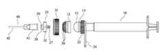
- FIG. 2is an exploded view of the assembly of FIG. 1 .
- FIG. 3is a detailed view of an embodiment of a cannula hub for use with the applicator assembly.
- FIG. 4Ais an exploded view showing a nub and its associated soft applicator cover in an embodiment of the invention.
- FIG. 4Bshows a nub with a soft applicator cover attached.
- FIG. 4Cshows the nub and applicator of FIGS. 4A and 4B with a securing collar attached.
- FIG. 5Ashows an embodiment of a connector between the nub and a cannula hub.
- FIG. 5Bshows a side view of the connector of FIG. 5A .
- FIG. 6shows another embodiment of the invention, in which a soft applicator cover fits over a cannula and hub attached to a syringe.
- FIG. 7shows an exploded view of the embodiment of FIG. 6 with a portion of the applicator cut away.
- FIG. 8shows a perspective view of the embodiment of FIG. 6 .
- FIG. 9shows and exploded view of another embodiment of the invention, in which a soft applicator cover fits directly onto a syringe.
- FIG. 10shows a perspective view of the embodiment of FIG. 9 .
- FIGS. 1 and 2An embodiment of the applicator assembly is shown in FIGS. 1 and 2 .
- An applicator assembly 30attaches to a barrel syringe 10 , which may be a standard luer lock syringe.
- a connector 25removably attaches a cannula 40 , which may be a common hub-and-cannula unit, to the applicator 30 .
- Applicator 30comprises an attachment nub 11 that fits into the syringe 10 and a soft applicator cover 12 that fits tightly over the nub 11
- Connection of the attachment nub 11 to the syringe 10may be by luer lock, in which the nub has a male luer configuration matching the female luer threads on the syringe. Other connections may be used, such as threading or a friction fit.
- nub 11may have a 360 degree groove 13 that matches to a 360 degree inward peripheral ridge 14 in the applicator cover 12 .
- the soft polymer applicatoritself is a cover 12 with a rounded tip 15 that fits tightly over a hemispheric nub 11 . It may be made of medical grade thermoplastic resin or medical grade silicone. It incorporates a plurality of soft filament projections, or tendrils 20 , about 3/16 inch (4.75 mm) long and 0.8 mm in diameter radiating outward. These “koosh” extensions allow effective dispersion of a viscous liquid while remaining comfortable to the skin. Different filament characteristics may be employed depending on the specific use for the applicator. For example, in the event of hair restoration, a modified silicone membrane with longer, stiffer extensions may provide a means of reducing the resistance of the hair as the applicator is being moved to distribute the liquid.
- the nub 11 that supports a soft tip covering 12may be any hard material, and is preferably a plastic, such as polypropylene. See FIGS. 4A-4C . As noted, the nub 11 engages the syringe in some manner In an embodiment, a proximal cylindrical extension of the nub 11 has male luer threads 16 that fit female luer threads (not shown) on the syringe. A tunnel or lumen 17 extends through the nub, terminating in an aperture 18 for liquid flow.
- the applicator coverhas a corresponding aperture 19 .
- a central cylindrical segment of the nubmay include external threads 22 that engage threads in a securing collar 31 that helps hold the applicator cover in place.
- an external peripheral ridge 23may be added to the above mentioned internal peripheral ridge in the applicator cover.
- An optional stand 24which may be plastic, snaps onto the nub 11 to keep the tip off the table surface.
- the distal portion of the nubis configured to optionally engage a cannula connector 25 .
- the connectormay be a two way male threaded cross shaped fitting 25 , with a central segment comprising a cross bar 32 , a proximal extension 27 adapted to engage female connector threads 26 on the nub 11 , and a distal extension 28 , adapted to engage a cannula hub 41 .
- a lumen 29 through the connectorpermits liquid to pass between the nub and the cannula.
- Other connection meanssuch as friction fit to the nub, or threaded fit to the cannula hub, may be employed.
- Some cannula hubshave external male luer lock threads, and an appropriate configuration might incorporate corresponding female threads on the distal extension of the connector.
- the cross bar 32 of the connector 25allows the user to easily twist the connector, unscrewing it and separating the applicator tip from the cannula.
- the cannula connectoris also sterile and removable.
- the connectormay comprise a fitting that substitutes a partially knurled disk 33 for the cross bar.
- a cannula assembly 40comprising a cannula 42 and cannula hub 41 are attached to the distal end of the assembly.
- Cannula hubs of various typesare known in the industry and provide a funnel-like transition from a wider aperture, such as in a syringe, to the narrow lumen of a small, usually metal, cannula. Most cannula hubs are hard plastic, but other materials, such as aluminum may be suitable.
- An embodiment of a cannula hubis shown in FIG. 3 .
- the proximal endis a cylindrical chamber 43 that tapers toward its distal end.
- An upper flange 44surrounds the opening and there may be male luer threads around the outside.
- the inner surface 45 of the chamberis smooth.
- the distal end 46 of the hubtapers more severely than the upper chamber, resulting in an opening that firmly engages the cannula 42
- the most common cannula sizes for skin and blood applicationsare between 20 gauge and 12 gauge
- cannula 42may be used to draw liquid into syringe 10 and may then be disengaged by detaching connector 25 thereby uncovering the applicator 30 for use in spreading the syringe contents onto the skin.
- FIGS. 6-8Another embodiment of the invention is shown in FIGS. 6-8 .
- This embodimentis useful when the user starts with prepackaged treatment liquid provided in a syringe with an attached cannula and hub.
- This embodimentcomprises a soft applicator block 50 , made of medical grade thermoplastic resin or medical grade silicone, fitted over the cannula assembly 40 .
- Internal cavity 51is configured to conform to the shape of the cannula assembly 40 so that it fits snugly over it.
- the cavityextends to an aperture 52 in the distal end of the block, having a diameter approximately that of the associated cannula.
- the cavityis configured so that distal end 47 of cannula 42 is stopped about 1 ⁇ 8′′ short of aperture 52 .
- FIGS. 9 & 10Another embodiment of the invention is shown in FIGS. 9 & 10 .
- This embodimentis similar to the embodiment in FIG. 7 , except that the soft applicator 60 is configured to fit over the tip of the syringe itself
- the soft applicator 60includes a lumen 61 that aligns with the output aperture of the syringe.
Landscapes
- Health & Medical Sciences (AREA)
- Engineering & Computer Science (AREA)
- Anesthesiology (AREA)
- Biomedical Technology (AREA)
- Heart & Thoracic Surgery (AREA)
- Hematology (AREA)
- Life Sciences & Earth Sciences (AREA)
- Animal Behavior & Ethology (AREA)
- General Health & Medical Sciences (AREA)
- Public Health (AREA)
- Veterinary Medicine (AREA)
- Infusion, Injection, And Reservoir Apparatuses (AREA)
- Media Introduction/Drainage Providing Device (AREA)
Abstract
Description
Claims (5)
Priority Applications (2)
| Application Number | Priority Date | Filing Date | Title |
|---|---|---|---|
| US15/978,928US10441763B2 (en) | 2017-11-17 | 2018-05-14 | Sterile applicator assembly |
| US16/379,525US10434294B2 (en) | 2017-11-17 | 2019-04-09 | Sterile applicator assembly with microneedle array |
Applications Claiming Priority (2)
| Application Number | Priority Date | Filing Date | Title |
|---|---|---|---|
| US201762588233P | 2017-11-17 | 2017-11-17 | |
| US15/978,928US10441763B2 (en) | 2017-11-17 | 2018-05-14 | Sterile applicator assembly |
Related Child Applications (1)
| Application Number | Title | Priority Date | Filing Date |
|---|---|---|---|
| US16/379,525Continuation-In-PartUS10434294B2 (en) | 2017-11-17 | 2019-04-09 | Sterile applicator assembly with microneedle array |
Publications (2)
| Publication Number | Publication Date |
|---|---|
| US20190151637A1 US20190151637A1 (en) | 2019-05-23 |
| US10441763B2true US10441763B2 (en) | 2019-10-15 |
Family
ID=66534162
Family Applications (1)
| Application Number | Title | Priority Date | Filing Date |
|---|---|---|---|
| US15/978,928ActiveUS10441763B2 (en) | 2017-11-17 | 2018-05-14 | Sterile applicator assembly |
Country Status (1)
| Country | Link |
|---|---|
| US (1) | US10441763B2 (en) |
Cited By (1)
| Publication number | Priority date | Publication date | Assignee | Title |
|---|---|---|---|---|
| US20230211360A1 (en)* | 2018-11-21 | 2023-07-06 | Inter-Med, Inc. | Universal minimal waste dispensing tip |
Families Citing this family (14)
| Publication number | Priority date | Publication date | Assignee | Title |
|---|---|---|---|---|
| US8048089B2 (en) | 2005-12-30 | 2011-11-01 | Edge Systems Corporation | Apparatus and methods for treating the skin |
| US9566088B2 (en) | 2006-03-29 | 2017-02-14 | Edge Systems Llc | Devices, systems and methods for treating the skin |
| KR20100129269A (en) | 2008-01-04 | 2010-12-08 | 엣지 시스템즈 코포레이션 | Skin treatment device and method |
| US9056193B2 (en) | 2008-01-29 | 2015-06-16 | Edge Systems Llc | Apparatus and method for treating the skin |
| EP3437575B1 (en) | 2013-03-15 | 2021-04-21 | Edge Systems LLC | Devices and systems for treating the skin |
| EP4324414A3 (en) | 2014-12-23 | 2024-05-01 | HydraFacial LLC | Devices and methods for treating the skin using a rollerball or a wicking member |
| US10179229B2 (en) | 2014-12-23 | 2019-01-15 | Edge Systems Llc | Devices and methods for treating the skin using a porous member |
| JP2018527052A (en) | 2015-07-08 | 2018-09-20 | エッジ システムズ エルエルシー | Apparatus, system and method for promoting hair growth |
| US11291474B2 (en) | 2020-01-06 | 2022-04-05 | Ed F. Nicolas | Skin treatment tool applicator tip |
| US10967163B1 (en)* | 2020-08-10 | 2021-04-06 | Esthetic Education LLC | Sterile applicator assembly with hollow microneedle array |
| USD1065551S1 (en) | 2021-09-10 | 2025-03-04 | Hydrafacial Llc | Skin treatment device |
| USD1016615S1 (en) | 2021-09-10 | 2024-03-05 | Hydrafacial Llc | Container for a skin treatment device |
| USD1042807S1 (en) | 2021-10-11 | 2024-09-17 | Hydrafacial Llc | Skin treatment tip |
| USD1084369S1 (en) | 2023-02-10 | 2025-07-15 | Hydrafacial Llc | Skin treatment tip |
Citations (6)
| Publication number | Priority date | Publication date | Assignee | Title |
|---|---|---|---|---|
| US1467242A (en)* | 1921-07-25 | 1923-09-04 | Mordechai A Elstein | Syringe |
| US6238120B1 (en)* | 2000-04-07 | 2001-05-29 | Phillip E. Mark | Fluid applicator |
| US6439241B2 (en)* | 1999-12-13 | 2002-08-27 | Joseph J. Berke | Method for applying health and beauty products to difficult and hard to reach body areas |
| US8857004B1 (en)* | 2010-10-05 | 2014-10-14 | Rene Jose Luis | Oral hygiene device |
| US8938841B1 (en)* | 2012-10-10 | 2015-01-27 | Jose A. Ramirez | Tooth brushing system |
| US20160279342A1 (en)* | 2013-12-31 | 2016-09-29 | Saferwith, Inc. | Syringe needle assembly, and safety syringe and safety syringe device using the syringe needle assembly |
- 2018
- 2018-05-14USUS15/978,928patent/US10441763B2/enactiveActive
Patent Citations (6)
| Publication number | Priority date | Publication date | Assignee | Title |
|---|---|---|---|---|
| US1467242A (en)* | 1921-07-25 | 1923-09-04 | Mordechai A Elstein | Syringe |
| US6439241B2 (en)* | 1999-12-13 | 2002-08-27 | Joseph J. Berke | Method for applying health and beauty products to difficult and hard to reach body areas |
| US6238120B1 (en)* | 2000-04-07 | 2001-05-29 | Phillip E. Mark | Fluid applicator |
| US8857004B1 (en)* | 2010-10-05 | 2014-10-14 | Rene Jose Luis | Oral hygiene device |
| US8938841B1 (en)* | 2012-10-10 | 2015-01-27 | Jose A. Ramirez | Tooth brushing system |
| US20160279342A1 (en)* | 2013-12-31 | 2016-09-29 | Saferwith, Inc. | Syringe needle assembly, and safety syringe and safety syringe device using the syringe needle assembly |
Cited By (2)
| Publication number | Priority date | Publication date | Assignee | Title |
|---|---|---|---|---|
| US20230211360A1 (en)* | 2018-11-21 | 2023-07-06 | Inter-Med, Inc. | Universal minimal waste dispensing tip |
| US12214367B2 (en)* | 2018-11-21 | 2025-02-04 | Inter-Med, Inc. | Universal minimal waste dispensing tip |
Also Published As
| Publication number | Publication date |
|---|---|
| US20190151637A1 (en) | 2019-05-23 |
Similar Documents
| Publication | Publication Date | Title |
|---|---|---|
| US10441763B2 (en) | Sterile applicator assembly | |
| JP5161259B2 (en) | Liquid drug medical equipment | |
| US8715242B2 (en) | Snap-seal sterile intravascular catheter-dressing system | |
| US20110202035A1 (en) | Syringe Assemblies Having Detachable Needle Assemblies and Low Dead Space | |
| JP5762413B2 (en) | Assembly kit for manufacturing prefilled syringes | |
| IL266437A (en) | Liquid transfer devices with integral telescopic vial adapter for use with infusion liquid container and discrete injection vial | |
| US10434294B2 (en) | Sterile applicator assembly with microneedle array | |
| KR102479658B1 (en) | Container closure operated by connecting device | |
| US20070225658A1 (en) | Unit Dose Delivery Systems | |
| US11602616B2 (en) | Adhesive encased protective caps for needle devices and related methods | |
| EP3375472B1 (en) | Pen-like portable device for cleaning needle-free iv-connectors | |
| KR20190102176A (en) | Container stopper operated by rotation | |
| US11090438B2 (en) | Slanted syringe handle | |
| US10967163B1 (en) | Sterile applicator assembly with hollow microneedle array | |
| KR102083843B1 (en) | Disposable sterilization set for semi-permanent makeup operation | |
| US20190099592A1 (en) | Disinfecting intravenous connectors | |
| EP2311512A2 (en) | Syringe assemblies having detachable needle assemblies and low dead space | |
| US11925793B2 (en) | Apparatus for injecting a fluid, comprising a needle assembly and a needle retention device for retaining a needle of the needle assembly when attached to the apparatus, and needle retention device | |
| JP7287975B2 (en) | Protective sleeve as cover sleeve for medical syringes | |
| CN114728153A (en) | Applicator device and method of use | |
| EP3723829A1 (en) | Device for the application of injections | |
| US9750893B1 (en) | Syringe and swab system | |
| RU233475U1 (en) | PROTECTIVE CASE FOR SYRINGE FOR INJECTING VISCOELASTIC SOLUTIONS | |
| TW201517945A (en) | Cap with dispenser | |
| US20240335621A1 (en) | Closure cap and closure system for a syringe that is prefilled with a medicament or medical active substance |
Legal Events
| Date | Code | Title | Description |
|---|---|---|---|
| AS | Assignment | Owner name:ESTHETIC EDUCATION LLC, ARIZONA Free format text:ASSIGNMENT OF ASSIGNORS INTEREST;ASSIGNORS:GROOP, KRISTIN;GROOP, LAWRENCE G;REEL/FRAME:045799/0674 Effective date:20180514 | |
| FEPP | Fee payment procedure | Free format text:ENTITY STATUS SET TO UNDISCOUNTED (ORIGINAL EVENT CODE: BIG.); ENTITY STATUS OF PATENT OWNER: SMALL ENTITY | |
| FEPP | Fee payment procedure | Free format text:ENTITY STATUS SET TO SMALL (ORIGINAL EVENT CODE: SMAL); ENTITY STATUS OF PATENT OWNER: SMALL ENTITY | |
| STPP | Information on status: patent application and granting procedure in general | Free format text:RESPONSE TO NON-FINAL OFFICE ACTION ENTERED AND FORWARDED TO EXAMINER | |
| STPP | Information on status: patent application and granting procedure in general | Free format text:FINAL REJECTION MAILED | |
| STPP | Information on status: patent application and granting procedure in general | Free format text:RESPONSE AFTER FINAL ACTION FORWARDED TO EXAMINER | |
| STPP | Information on status: patent application and granting procedure in general | Free format text:NOTICE OF ALLOWANCE MAILED -- APPLICATION RECEIVED IN OFFICE OF PUBLICATIONS | |
| STPP | Information on status: patent application and granting procedure in general | Free format text:PUBLICATIONS -- ISSUE FEE PAYMENT RECEIVED | |
| STCF | Information on status: patent grant | Free format text:PATENTED CASE | |
| MAFP | Maintenance fee payment | Free format text:PAYMENT OF MAINTENANCE FEE, 4TH YR, SMALL ENTITY (ORIGINAL EVENT CODE: M2551); ENTITY STATUS OF PATENT OWNER: SMALL ENTITY Year of fee payment:4 | |
| AS | Assignment | Owner name:ESTHETIC ADVISOR LLC, ARIZONA Free format text:ASSIGNMENT OF ASSIGNORS INTEREST;ASSIGNOR:ESTHETIC EDUCATION LLC;REEL/FRAME:069359/0009 Effective date:20241022 |