US10441745B2 - Neurovascular catheter with enlargeable distal end - Google Patents
Neurovascular catheter with enlargeable distal endDownload PDFInfo
- Publication number
- US10441745B2 US10441745B2US15/443,948US201715443948AUS10441745B2US 10441745 B2US10441745 B2US 10441745B2US 201715443948 AUS201715443948 AUS 201715443948AUS 10441745 B2US10441745 B2US 10441745B2
- Authority
- US
- United States
- Prior art keywords
- catheter
- distal
- proximal
- tubular
- distal end
- Prior art date
- Legal status (The legal status is an assumption and is not a legal conclusion. Google has not performed a legal analysis and makes no representation as to the accuracy of the status listed.)
- Active
Links
Images


Classifications
- A—HUMAN NECESSITIES
- A61—MEDICAL OR VETERINARY SCIENCE; HYGIENE
- A61M—DEVICES FOR INTRODUCING MEDIA INTO, OR ONTO, THE BODY; DEVICES FOR TRANSDUCING BODY MEDIA OR FOR TAKING MEDIA FROM THE BODY; DEVICES FOR PRODUCING OR ENDING SLEEP OR STUPOR
- A61M25/00—Catheters; Hollow probes
- A61M25/0043—Catheters; Hollow probes characterised by structural features
- A61M25/005—Catheters; Hollow probes characterised by structural features with embedded materials for reinforcement, e.g. wires, coils, braids
- A61M25/0053—Catheters; Hollow probes characterised by structural features with embedded materials for reinforcement, e.g. wires, coils, braids having a variable stiffness along the longitudinal axis, e.g. by varying the pitch of the coil or braid
- A—HUMAN NECESSITIES
- A61—MEDICAL OR VETERINARY SCIENCE; HYGIENE
- A61B—DIAGNOSIS; SURGERY; IDENTIFICATION
- A61B17/00—Surgical instruments, devices or methods
- A61B17/12—Surgical instruments, devices or methods for ligaturing or otherwise compressing tubular parts of the body, e.g. blood vessels or umbilical cord
- A61B17/12022—Occluding by internal devices, e.g. balloons or releasable wires
- A61B17/12131—Occluding by internal devices, e.g. balloons or releasable wires characterised by the type of occluding device
- A61B17/12168—Occluding by internal devices, e.g. balloons or releasable wires characterised by the type of occluding device having a mesh structure
- A—HUMAN NECESSITIES
- A61—MEDICAL OR VETERINARY SCIENCE; HYGIENE
- A61B—DIAGNOSIS; SURGERY; IDENTIFICATION
- A61B17/00—Surgical instruments, devices or methods
- A61B17/12—Surgical instruments, devices or methods for ligaturing or otherwise compressing tubular parts of the body, e.g. blood vessels or umbilical cord
- A61B17/12022—Occluding by internal devices, e.g. balloons or releasable wires
- A61B17/12131—Occluding by internal devices, e.g. balloons or releasable wires characterised by the type of occluding device
- A61B17/12181—Occluding by internal devices, e.g. balloons or releasable wires characterised by the type of occluding device formed by fluidized, gelatinous or cellular remodelable materials, e.g. embolic liquids, foams or extracellular matrices
- A61B17/12186—Occluding by internal devices, e.g. balloons or releasable wires characterised by the type of occluding device formed by fluidized, gelatinous or cellular remodelable materials, e.g. embolic liquids, foams or extracellular matrices liquid materials adapted to be injected
- A—HUMAN NECESSITIES
- A61—MEDICAL OR VETERINARY SCIENCE; HYGIENE
- A61B—DIAGNOSIS; SURGERY; IDENTIFICATION
- A61B17/00—Surgical instruments, devices or methods
- A61B17/22—Implements for squeezing-off ulcers or the like on inner organs of the body; Implements for scraping-out cavities of body organs, e.g. bones; for invasive removal or destruction of calculus using mechanical vibrations; for removing obstructions in blood vessels, not otherwise provided for
- A61B17/22004—Implements for squeezing-off ulcers or the like on inner organs of the body; Implements for scraping-out cavities of body organs, e.g. bones; for invasive removal or destruction of calculus using mechanical vibrations; for removing obstructions in blood vessels, not otherwise provided for using mechanical vibrations, e.g. ultrasonic shock waves
- A61B17/22012—Implements for squeezing-off ulcers or the like on inner organs of the body; Implements for scraping-out cavities of body organs, e.g. bones; for invasive removal or destruction of calculus using mechanical vibrations; for removing obstructions in blood vessels, not otherwise provided for using mechanical vibrations, e.g. ultrasonic shock waves in direct contact with, or very close to, the obstruction or concrement
- A61B17/2202—Implements for squeezing-off ulcers or the like on inner organs of the body; Implements for scraping-out cavities of body organs, e.g. bones; for invasive removal or destruction of calculus using mechanical vibrations; for removing obstructions in blood vessels, not otherwise provided for using mechanical vibrations, e.g. ultrasonic shock waves in direct contact with, or very close to, the obstruction or concrement the ultrasound transducer being inside patient's body at the distal end of the catheter
- A—HUMAN NECESSITIES
- A61—MEDICAL OR VETERINARY SCIENCE; HYGIENE
- A61B—DIAGNOSIS; SURGERY; IDENTIFICATION
- A61B17/00—Surgical instruments, devices or methods
- A61B17/22—Implements for squeezing-off ulcers or the like on inner organs of the body; Implements for scraping-out cavities of body organs, e.g. bones; for invasive removal or destruction of calculus using mechanical vibrations; for removing obstructions in blood vessels, not otherwise provided for
- A61B17/22031—Gripping instruments, e.g. forceps, for removing or smashing calculi
- A—HUMAN NECESSITIES
- A61—MEDICAL OR VETERINARY SCIENCE; HYGIENE
- A61B—DIAGNOSIS; SURGERY; IDENTIFICATION
- A61B17/00—Surgical instruments, devices or methods
- A61B17/32—Surgical cutting instruments
- A61B17/3203—Fluid jet cutting instruments
- A—HUMAN NECESSITIES
- A61—MEDICAL OR VETERINARY SCIENCE; HYGIENE
- A61B—DIAGNOSIS; SURGERY; IDENTIFICATION
- A61B17/00—Surgical instruments, devices or methods
- A61B17/32—Surgical cutting instruments
- A61B17/3203—Fluid jet cutting instruments
- A61B17/32037—Fluid jet cutting instruments for removing obstructions from inner organs or blood vessels, e.g. for atherectomy
- A—HUMAN NECESSITIES
- A61—MEDICAL OR VETERINARY SCIENCE; HYGIENE
- A61B—DIAGNOSIS; SURGERY; IDENTIFICATION
- A61B17/00—Surgical instruments, devices or methods
- A61B17/32—Surgical cutting instruments
- A61B17/3205—Excision instruments
- A61B17/3207—Atherectomy devices working by cutting or abrading; Similar devices specially adapted for non-vascular obstructions
- A61B17/320725—Atherectomy devices working by cutting or abrading; Similar devices specially adapted for non-vascular obstructions with radially expandable cutting or abrading elements
- A—HUMAN NECESSITIES
- A61—MEDICAL OR VETERINARY SCIENCE; HYGIENE
- A61B—DIAGNOSIS; SURGERY; IDENTIFICATION
- A61B17/00—Surgical instruments, devices or methods
- A61B17/32—Surgical cutting instruments
- A61B17/3205—Excision instruments
- A61B17/3207—Atherectomy devices working by cutting or abrading; Similar devices specially adapted for non-vascular obstructions
- A61B17/320758—Atherectomy devices working by cutting or abrading; Similar devices specially adapted for non-vascular obstructions with a rotating cutting instrument, e.g. motor driven
- A—HUMAN NECESSITIES
- A61—MEDICAL OR VETERINARY SCIENCE; HYGIENE
- A61B—DIAGNOSIS; SURGERY; IDENTIFICATION
- A61B6/00—Apparatus or devices for radiation diagnosis; Apparatus or devices for radiation diagnosis combined with radiation therapy equipment
- A61B6/48—Diagnostic techniques
- A61B6/481—Diagnostic techniques involving the use of contrast agents
- A—HUMAN NECESSITIES
- A61—MEDICAL OR VETERINARY SCIENCE; HYGIENE
- A61B—DIAGNOSIS; SURGERY; IDENTIFICATION
- A61B6/00—Apparatus or devices for radiation diagnosis; Apparatus or devices for radiation diagnosis combined with radiation therapy equipment
- A61B6/50—Apparatus or devices for radiation diagnosis; Apparatus or devices for radiation diagnosis combined with radiation therapy equipment specially adapted for specific body parts; specially adapted for specific clinical applications
- A61B6/501—Apparatus or devices for radiation diagnosis; Apparatus or devices for radiation diagnosis combined with radiation therapy equipment specially adapted for specific body parts; specially adapted for specific clinical applications for diagnosis of the head, e.g. neuroimaging or craniography
- A—HUMAN NECESSITIES
- A61—MEDICAL OR VETERINARY SCIENCE; HYGIENE
- A61F—FILTERS IMPLANTABLE INTO BLOOD VESSELS; PROSTHESES; DEVICES PROVIDING PATENCY TO, OR PREVENTING COLLAPSING OF, TUBULAR STRUCTURES OF THE BODY, e.g. STENTS; ORTHOPAEDIC, NURSING OR CONTRACEPTIVE DEVICES; FOMENTATION; TREATMENT OR PROTECTION OF EYES OR EARS; BANDAGES, DRESSINGS OR ABSORBENT PADS; FIRST-AID KITS
- A61F2/00—Filters implantable into blood vessels; Prostheses, i.e. artificial substitutes or replacements for parts of the body; Appliances for connecting them with the body; Devices providing patency to, or preventing collapsing of, tubular structures of the body, e.g. stents
- A61F2/95—Instruments specially adapted for placement or removal of stents or stent-grafts
- A—HUMAN NECESSITIES
- A61—MEDICAL OR VETERINARY SCIENCE; HYGIENE
- A61F—FILTERS IMPLANTABLE INTO BLOOD VESSELS; PROSTHESES; DEVICES PROVIDING PATENCY TO, OR PREVENTING COLLAPSING OF, TUBULAR STRUCTURES OF THE BODY, e.g. STENTS; ORTHOPAEDIC, NURSING OR CONTRACEPTIVE DEVICES; FOMENTATION; TREATMENT OR PROTECTION OF EYES OR EARS; BANDAGES, DRESSINGS OR ABSORBENT PADS; FIRST-AID KITS
- A61F7/00—Heating or cooling appliances for medical or therapeutic treatment of the human body
- A61F7/12—Devices for heating or cooling internal body cavities
- A—HUMAN NECESSITIES
- A61—MEDICAL OR VETERINARY SCIENCE; HYGIENE
- A61L—METHODS OR APPARATUS FOR STERILISING MATERIALS OR OBJECTS IN GENERAL; DISINFECTION, STERILISATION OR DEODORISATION OF AIR; CHEMICAL ASPECTS OF BANDAGES, DRESSINGS, ABSORBENT PADS OR SURGICAL ARTICLES; MATERIALS FOR BANDAGES, DRESSINGS, ABSORBENT PADS OR SURGICAL ARTICLES
- A61L29/00—Materials for catheters, medical tubing, cannulae, or endoscopes or for coating catheters
- A61L29/02—Inorganic materials
- A—HUMAN NECESSITIES
- A61—MEDICAL OR VETERINARY SCIENCE; HYGIENE
- A61L—METHODS OR APPARATUS FOR STERILISING MATERIALS OR OBJECTS IN GENERAL; DISINFECTION, STERILISATION OR DEODORISATION OF AIR; CHEMICAL ASPECTS OF BANDAGES, DRESSINGS, ABSORBENT PADS OR SURGICAL ARTICLES; MATERIALS FOR BANDAGES, DRESSINGS, ABSORBENT PADS OR SURGICAL ARTICLES
- A61L29/00—Materials for catheters, medical tubing, cannulae, or endoscopes or for coating catheters
- A61L29/04—Macromolecular materials
- A61L29/041—Macromolecular materials obtained by reactions only involving carbon-to-carbon unsaturated bonds
- A—HUMAN NECESSITIES
- A61—MEDICAL OR VETERINARY SCIENCE; HYGIENE
- A61L—METHODS OR APPARATUS FOR STERILISING MATERIALS OR OBJECTS IN GENERAL; DISINFECTION, STERILISATION OR DEODORISATION OF AIR; CHEMICAL ASPECTS OF BANDAGES, DRESSINGS, ABSORBENT PADS OR SURGICAL ARTICLES; MATERIALS FOR BANDAGES, DRESSINGS, ABSORBENT PADS OR SURGICAL ARTICLES
- A61L29/00—Materials for catheters, medical tubing, cannulae, or endoscopes or for coating catheters
- A61L29/04—Macromolecular materials
- A61L29/06—Macromolecular materials obtained otherwise than by reactions only involving carbon-to-carbon unsaturated bonds
- A—HUMAN NECESSITIES
- A61—MEDICAL OR VETERINARY SCIENCE; HYGIENE
- A61L—METHODS OR APPARATUS FOR STERILISING MATERIALS OR OBJECTS IN GENERAL; DISINFECTION, STERILISATION OR DEODORISATION OF AIR; CHEMICAL ASPECTS OF BANDAGES, DRESSINGS, ABSORBENT PADS OR SURGICAL ARTICLES; MATERIALS FOR BANDAGES, DRESSINGS, ABSORBENT PADS OR SURGICAL ARTICLES
- A61L29/00—Materials for catheters, medical tubing, cannulae, or endoscopes or for coating catheters
- A61L29/14—Materials characterised by their function or physical properties, e.g. lubricating compositions
- A61M1/0035—
- A61M1/0066—
- A—HUMAN NECESSITIES
- A61—MEDICAL OR VETERINARY SCIENCE; HYGIENE
- A61M—DEVICES FOR INTRODUCING MEDIA INTO, OR ONTO, THE BODY; DEVICES FOR TRANSDUCING BODY MEDIA OR FOR TAKING MEDIA FROM THE BODY; DEVICES FOR PRODUCING OR ENDING SLEEP OR STUPOR
- A61M1/00—Suction or pumping devices for medical purposes; Devices for carrying-off, for treatment of, or for carrying-over, body-liquids; Drainage systems
- A61M1/14—Dialysis systems; Artificial kidneys; Blood oxygenators ; Reciprocating systems for treatment of body fluids, e.g. single needle systems for hemofiltration or pheresis
- A61M1/32—Oxygenators without membranes
- A—HUMAN NECESSITIES
- A61—MEDICAL OR VETERINARY SCIENCE; HYGIENE
- A61M—DEVICES FOR INTRODUCING MEDIA INTO, OR ONTO, THE BODY; DEVICES FOR TRANSDUCING BODY MEDIA OR FOR TAKING MEDIA FROM THE BODY; DEVICES FOR PRODUCING OR ENDING SLEEP OR STUPOR
- A61M1/00—Suction or pumping devices for medical purposes; Devices for carrying-off, for treatment of, or for carrying-over, body-liquids; Drainage systems
- A61M1/71—Suction drainage systems
- A61M1/74—Suction control
- A61M1/743—Suction control by changing the cross-section of the line, e.g. flow regulating valves
- A—HUMAN NECESSITIES
- A61—MEDICAL OR VETERINARY SCIENCE; HYGIENE
- A61M—DEVICES FOR INTRODUCING MEDIA INTO, OR ONTO, THE BODY; DEVICES FOR TRANSDUCING BODY MEDIA OR FOR TAKING MEDIA FROM THE BODY; DEVICES FOR PRODUCING OR ENDING SLEEP OR STUPOR
- A61M1/00—Suction or pumping devices for medical purposes; Devices for carrying-off, for treatment of, or for carrying-over, body-liquids; Drainage systems
- A61M1/80—Suction pumps
- A—HUMAN NECESSITIES
- A61—MEDICAL OR VETERINARY SCIENCE; HYGIENE
- A61M—DEVICES FOR INTRODUCING MEDIA INTO, OR ONTO, THE BODY; DEVICES FOR TRANSDUCING BODY MEDIA OR FOR TAKING MEDIA FROM THE BODY; DEVICES FOR PRODUCING OR ENDING SLEEP OR STUPOR
- A61M25/00—Catheters; Hollow probes
- A61M25/0009—Making of catheters or other medical or surgical tubes
- A61M25/0012—Making of catheters or other medical or surgical tubes with embedded structures, e.g. coils, braids, meshes, strands or radiopaque coils
- A—HUMAN NECESSITIES
- A61—MEDICAL OR VETERINARY SCIENCE; HYGIENE
- A61M—DEVICES FOR INTRODUCING MEDIA INTO, OR ONTO, THE BODY; DEVICES FOR TRANSDUCING BODY MEDIA OR FOR TAKING MEDIA FROM THE BODY; DEVICES FOR PRODUCING OR ENDING SLEEP OR STUPOR
- A61M25/00—Catheters; Hollow probes
- A61M25/0021—Catheters; Hollow probes characterised by the form of the tubing
- A61M25/0023—Catheters; Hollow probes characterised by the form of the tubing by the form of the lumen, e.g. cross-section, variable diameter
- A—HUMAN NECESSITIES
- A61—MEDICAL OR VETERINARY SCIENCE; HYGIENE
- A61M—DEVICES FOR INTRODUCING MEDIA INTO, OR ONTO, THE BODY; DEVICES FOR TRANSDUCING BODY MEDIA OR FOR TAKING MEDIA FROM THE BODY; DEVICES FOR PRODUCING OR ENDING SLEEP OR STUPOR
- A61M25/00—Catheters; Hollow probes
- A61M25/0043—Catheters; Hollow probes characterised by structural features
- A61M25/0045—Catheters; Hollow probes characterised by structural features multi-layered, e.g. coated
- A—HUMAN NECESSITIES
- A61—MEDICAL OR VETERINARY SCIENCE; HYGIENE
- A61M—DEVICES FOR INTRODUCING MEDIA INTO, OR ONTO, THE BODY; DEVICES FOR TRANSDUCING BODY MEDIA OR FOR TAKING MEDIA FROM THE BODY; DEVICES FOR PRODUCING OR ENDING SLEEP OR STUPOR
- A61M25/00—Catheters; Hollow probes
- A61M25/0043—Catheters; Hollow probes characterised by structural features
- A61M25/005—Catheters; Hollow probes characterised by structural features with embedded materials for reinforcement, e.g. wires, coils, braids
- A—HUMAN NECESSITIES
- A61—MEDICAL OR VETERINARY SCIENCE; HYGIENE
- A61M—DEVICES FOR INTRODUCING MEDIA INTO, OR ONTO, THE BODY; DEVICES FOR TRANSDUCING BODY MEDIA OR FOR TAKING MEDIA FROM THE BODY; DEVICES FOR PRODUCING OR ENDING SLEEP OR STUPOR
- A61M25/00—Catheters; Hollow probes
- A61M25/0067—Catheters; Hollow probes characterised by the distal end, e.g. tips
- A61M25/0068—Static characteristics of the catheter tip, e.g. shape, atraumatic tip, curved tip or tip structure
- A61M25/007—Side holes, e.g. their profiles or arrangements; Provisions to keep side holes unblocked
- A—HUMAN NECESSITIES
- A61—MEDICAL OR VETERINARY SCIENCE; HYGIENE
- A61M—DEVICES FOR INTRODUCING MEDIA INTO, OR ONTO, THE BODY; DEVICES FOR TRANSDUCING BODY MEDIA OR FOR TAKING MEDIA FROM THE BODY; DEVICES FOR PRODUCING OR ENDING SLEEP OR STUPOR
- A61M25/00—Catheters; Hollow probes
- A61M25/0067—Catheters; Hollow probes characterised by the distal end, e.g. tips
- A61M25/0074—Dynamic characteristics of the catheter tip, e.g. openable, closable, expandable or deformable
- A—HUMAN NECESSITIES
- A61—MEDICAL OR VETERINARY SCIENCE; HYGIENE
- A61M—DEVICES FOR INTRODUCING MEDIA INTO, OR ONTO, THE BODY; DEVICES FOR TRANSDUCING BODY MEDIA OR FOR TAKING MEDIA FROM THE BODY; DEVICES FOR PRODUCING OR ENDING SLEEP OR STUPOR
- A61M25/00—Catheters; Hollow probes
- A61M25/0067—Catheters; Hollow probes characterised by the distal end, e.g. tips
- A61M25/008—Strength or flexibility characteristics of the catheter tip
- A—HUMAN NECESSITIES
- A61—MEDICAL OR VETERINARY SCIENCE; HYGIENE
- A61M—DEVICES FOR INTRODUCING MEDIA INTO, OR ONTO, THE BODY; DEVICES FOR TRANSDUCING BODY MEDIA OR FOR TAKING MEDIA FROM THE BODY; DEVICES FOR PRODUCING OR ENDING SLEEP OR STUPOR
- A61M25/00—Catheters; Hollow probes
- A61M25/0067—Catheters; Hollow probes characterised by the distal end, e.g. tips
- A61M25/0082—Catheter tip comprising a tool
- A—HUMAN NECESSITIES
- A61—MEDICAL OR VETERINARY SCIENCE; HYGIENE
- A61M—DEVICES FOR INTRODUCING MEDIA INTO, OR ONTO, THE BODY; DEVICES FOR TRANSDUCING BODY MEDIA OR FOR TAKING MEDIA FROM THE BODY; DEVICES FOR PRODUCING OR ENDING SLEEP OR STUPOR
- A61M25/00—Catheters; Hollow probes
- A61M25/0097—Catheters; Hollow probes characterised by the hub
- A—HUMAN NECESSITIES
- A61—MEDICAL OR VETERINARY SCIENCE; HYGIENE
- A61M—DEVICES FOR INTRODUCING MEDIA INTO, OR ONTO, THE BODY; DEVICES FOR TRANSDUCING BODY MEDIA OR FOR TAKING MEDIA FROM THE BODY; DEVICES FOR PRODUCING OR ENDING SLEEP OR STUPOR
- A61M25/00—Catheters; Hollow probes
- A61M25/01—Introducing, guiding, advancing, emplacing or holding catheters
- A61M25/0102—Insertion or introduction using an inner stiffening member, e.g. stylet or push-rod
- A—HUMAN NECESSITIES
- A61—MEDICAL OR VETERINARY SCIENCE; HYGIENE
- A61M—DEVICES FOR INTRODUCING MEDIA INTO, OR ONTO, THE BODY; DEVICES FOR TRANSDUCING BODY MEDIA OR FOR TAKING MEDIA FROM THE BODY; DEVICES FOR PRODUCING OR ENDING SLEEP OR STUPOR
- A61M25/00—Catheters; Hollow probes
- A61M25/01—Introducing, guiding, advancing, emplacing or holding catheters
- A61M25/0105—Steering means as part of the catheter or advancing means; Markers for positioning
- A61M25/0108—Steering means as part of the catheter or advancing means; Markers for positioning using radio-opaque or ultrasound markers
- A—HUMAN NECESSITIES
- A61—MEDICAL OR VETERINARY SCIENCE; HYGIENE
- A61M—DEVICES FOR INTRODUCING MEDIA INTO, OR ONTO, THE BODY; DEVICES FOR TRANSDUCING BODY MEDIA OR FOR TAKING MEDIA FROM THE BODY; DEVICES FOR PRODUCING OR ENDING SLEEP OR STUPOR
- A61M25/00—Catheters; Hollow probes
- A61M25/01—Introducing, guiding, advancing, emplacing or holding catheters
- A61M25/0105—Steering means as part of the catheter or advancing means; Markers for positioning
- A61M25/0133—Tip steering devices
- A61M25/0147—Tip steering devices with movable mechanical means, e.g. pull wires
- A—HUMAN NECESSITIES
- A61—MEDICAL OR VETERINARY SCIENCE; HYGIENE
- A61M—DEVICES FOR INTRODUCING MEDIA INTO, OR ONTO, THE BODY; DEVICES FOR TRANSDUCING BODY MEDIA OR FOR TAKING MEDIA FROM THE BODY; DEVICES FOR PRODUCING OR ENDING SLEEP OR STUPOR
- A61M25/00—Catheters; Hollow probes
- A61M25/01—Introducing, guiding, advancing, emplacing or holding catheters
- A61M25/06—Body-piercing guide needles or the like
- A61M25/0662—Guide tubes
- A—HUMAN NECESSITIES
- A61—MEDICAL OR VETERINARY SCIENCE; HYGIENE
- A61M—DEVICES FOR INTRODUCING MEDIA INTO, OR ONTO, THE BODY; DEVICES FOR TRANSDUCING BODY MEDIA OR FOR TAKING MEDIA FROM THE BODY; DEVICES FOR PRODUCING OR ENDING SLEEP OR STUPOR
- A61M25/00—Catheters; Hollow probes
- A61M25/01—Introducing, guiding, advancing, emplacing or holding catheters
- A61M25/09—Guide wires
- A—HUMAN NECESSITIES
- A61—MEDICAL OR VETERINARY SCIENCE; HYGIENE
- A61M—DEVICES FOR INTRODUCING MEDIA INTO, OR ONTO, THE BODY; DEVICES FOR TRANSDUCING BODY MEDIA OR FOR TAKING MEDIA FROM THE BODY; DEVICES FOR PRODUCING OR ENDING SLEEP OR STUPOR
- A61M25/00—Catheters; Hollow probes
- A61M25/10—Balloon catheters
- A61M25/1027—Making of balloon catheters
- A—HUMAN NECESSITIES
- A61—MEDICAL OR VETERINARY SCIENCE; HYGIENE
- A61M—DEVICES FOR INTRODUCING MEDIA INTO, OR ONTO, THE BODY; DEVICES FOR TRANSDUCING BODY MEDIA OR FOR TAKING MEDIA FROM THE BODY; DEVICES FOR PRODUCING OR ENDING SLEEP OR STUPOR
- A61M39/00—Tubes, tube connectors, tube couplings, valves, access sites or the like, specially adapted for medical use
- A61M39/02—Access sites
- A61M39/06—Haemostasis valves, i.e. gaskets sealing around a needle, catheter or the like, closing on removal thereof
- A—HUMAN NECESSITIES
- A61—MEDICAL OR VETERINARY SCIENCE; HYGIENE
- A61M—DEVICES FOR INTRODUCING MEDIA INTO, OR ONTO, THE BODY; DEVICES FOR TRANSDUCING BODY MEDIA OR FOR TAKING MEDIA FROM THE BODY; DEVICES FOR PRODUCING OR ENDING SLEEP OR STUPOR
- A61M5/00—Devices for bringing media into the body in a subcutaneous, intra-vascular or intramuscular way; Accessories therefor, e.g. filling or cleaning devices, arm-rests
- A61M5/007—Devices for bringing media into the body in a subcutaneous, intra-vascular or intramuscular way; Accessories therefor, e.g. filling or cleaning devices, arm-rests for contrast media
- B—PERFORMING OPERATIONS; TRANSPORTING
- B29—WORKING OF PLASTICS; WORKING OF SUBSTANCES IN A PLASTIC STATE IN GENERAL
- B29C—SHAPING OR JOINING OF PLASTICS; SHAPING OF MATERIAL IN A PLASTIC STATE, NOT OTHERWISE PROVIDED FOR; AFTER-TREATMENT OF THE SHAPED PRODUCTS, e.g. REPAIRING
- B29C41/00—Shaping by coating a mould, core or other substrate, i.e. by depositing material and stripping-off the shaped article; Apparatus therefor
- B29C41/02—Shaping by coating a mould, core or other substrate, i.e. by depositing material and stripping-off the shaped article; Apparatus therefor for making articles of definite length, i.e. discrete articles
- B29C41/14—Dipping a core
- A—HUMAN NECESSITIES
- A61—MEDICAL OR VETERINARY SCIENCE; HYGIENE
- A61B—DIAGNOSIS; SURGERY; IDENTIFICATION
- A61B17/00—Surgical instruments, devices or methods
- A61B17/22—Implements for squeezing-off ulcers or the like on inner organs of the body; Implements for scraping-out cavities of body organs, e.g. bones; for invasive removal or destruction of calculus using mechanical vibrations; for removing obstructions in blood vessels, not otherwise provided for
- A61B17/22004—Implements for squeezing-off ulcers or the like on inner organs of the body; Implements for scraping-out cavities of body organs, e.g. bones; for invasive removal or destruction of calculus using mechanical vibrations; for removing obstructions in blood vessels, not otherwise provided for using mechanical vibrations, e.g. ultrasonic shock waves
- A61B17/22012—Implements for squeezing-off ulcers or the like on inner organs of the body; Implements for scraping-out cavities of body organs, e.g. bones; for invasive removal or destruction of calculus using mechanical vibrations; for removing obstructions in blood vessels, not otherwise provided for using mechanical vibrations, e.g. ultrasonic shock waves in direct contact with, or very close to, the obstruction or concrement
- A—HUMAN NECESSITIES
- A61—MEDICAL OR VETERINARY SCIENCE; HYGIENE
- A61B—DIAGNOSIS; SURGERY; IDENTIFICATION
- A61B17/00—Surgical instruments, devices or methods
- A61B2017/00367—Details of actuation of instruments, e.g. relations between pushing buttons, or the like, and activation of the tool, working tip, or the like
- A61B2017/00398—Details of actuation of instruments, e.g. relations between pushing buttons, or the like, and activation of the tool, working tip, or the like using powered actuators, e.g. stepper motors, solenoids
- A—HUMAN NECESSITIES
- A61—MEDICAL OR VETERINARY SCIENCE; HYGIENE
- A61B—DIAGNOSIS; SURGERY; IDENTIFICATION
- A61B17/00—Surgical instruments, devices or methods
- A61B2017/00526—Methods of manufacturing
- A—HUMAN NECESSITIES
- A61—MEDICAL OR VETERINARY SCIENCE; HYGIENE
- A61B—DIAGNOSIS; SURGERY; IDENTIFICATION
- A61B17/00—Surgical instruments, devices or methods
- A61B2017/00681—Aspects not otherwise provided for
- A61B2017/00734—Aspects not otherwise provided for battery operated
- A—HUMAN NECESSITIES
- A61—MEDICAL OR VETERINARY SCIENCE; HYGIENE
- A61B—DIAGNOSIS; SURGERY; IDENTIFICATION
- A61B17/00—Surgical instruments, devices or methods
- A61B2017/00831—Material properties
- A61B2017/00862—Material properties elastic or resilient
- A—HUMAN NECESSITIES
- A61—MEDICAL OR VETERINARY SCIENCE; HYGIENE
- A61B—DIAGNOSIS; SURGERY; IDENTIFICATION
- A61B17/00—Surgical instruments, devices or methods
- A61B2017/00831—Material properties
- A61B2017/00867—Material properties shape memory effect
- A—HUMAN NECESSITIES
- A61—MEDICAL OR VETERINARY SCIENCE; HYGIENE
- A61B—DIAGNOSIS; SURGERY; IDENTIFICATION
- A61B17/00—Surgical instruments, devices or methods
- A61B2017/00831—Material properties
- A61B2017/00898—Material properties expandable upon contact with fluid
- A—HUMAN NECESSITIES
- A61—MEDICAL OR VETERINARY SCIENCE; HYGIENE
- A61B—DIAGNOSIS; SURGERY; IDENTIFICATION
- A61B17/00—Surgical instruments, devices or methods
- A61B2017/00831—Material properties
- A61B2017/00955—Material properties thermoplastic
- A—HUMAN NECESSITIES
- A61—MEDICAL OR VETERINARY SCIENCE; HYGIENE
- A61B—DIAGNOSIS; SURGERY; IDENTIFICATION
- A61B17/00—Surgical instruments, devices or methods
- A61B17/22—Implements for squeezing-off ulcers or the like on inner organs of the body; Implements for scraping-out cavities of body organs, e.g. bones; for invasive removal or destruction of calculus using mechanical vibrations; for removing obstructions in blood vessels, not otherwise provided for
- A61B17/22004—Implements for squeezing-off ulcers or the like on inner organs of the body; Implements for scraping-out cavities of body organs, e.g. bones; for invasive removal or destruction of calculus using mechanical vibrations; for removing obstructions in blood vessels, not otherwise provided for using mechanical vibrations, e.g. ultrasonic shock waves
- A61B17/22012—Implements for squeezing-off ulcers or the like on inner organs of the body; Implements for scraping-out cavities of body organs, e.g. bones; for invasive removal or destruction of calculus using mechanical vibrations; for removing obstructions in blood vessels, not otherwise provided for using mechanical vibrations, e.g. ultrasonic shock waves in direct contact with, or very close to, the obstruction or concrement
- A61B2017/22025—Implements for squeezing-off ulcers or the like on inner organs of the body; Implements for scraping-out cavities of body organs, e.g. bones; for invasive removal or destruction of calculus using mechanical vibrations; for removing obstructions in blood vessels, not otherwise provided for using mechanical vibrations, e.g. ultrasonic shock waves in direct contact with, or very close to, the obstruction or concrement applying a shock wave
- A—HUMAN NECESSITIES
- A61—MEDICAL OR VETERINARY SCIENCE; HYGIENE
- A61B—DIAGNOSIS; SURGERY; IDENTIFICATION
- A61B17/00—Surgical instruments, devices or methods
- A61B17/22—Implements for squeezing-off ulcers or the like on inner organs of the body; Implements for scraping-out cavities of body organs, e.g. bones; for invasive removal or destruction of calculus using mechanical vibrations; for removing obstructions in blood vessels, not otherwise provided for
- A61B17/22031—Gripping instruments, e.g. forceps, for removing or smashing calculi
- A61B2017/22034—Gripping instruments, e.g. forceps, for removing or smashing calculi for gripping the obstruction or the tissue part from inside
- A—HUMAN NECESSITIES
- A61—MEDICAL OR VETERINARY SCIENCE; HYGIENE
- A61B—DIAGNOSIS; SURGERY; IDENTIFICATION
- A61B17/00—Surgical instruments, devices or methods
- A61B17/22—Implements for squeezing-off ulcers or the like on inner organs of the body; Implements for scraping-out cavities of body organs, e.g. bones; for invasive removal or destruction of calculus using mechanical vibrations; for removing obstructions in blood vessels, not otherwise provided for
- A61B2017/22038—Implements for squeezing-off ulcers or the like on inner organs of the body; Implements for scraping-out cavities of body organs, e.g. bones; for invasive removal or destruction of calculus using mechanical vibrations; for removing obstructions in blood vessels, not otherwise provided for with a guide wire
- A—HUMAN NECESSITIES
- A61—MEDICAL OR VETERINARY SCIENCE; HYGIENE
- A61B—DIAGNOSIS; SURGERY; IDENTIFICATION
- A61B17/00—Surgical instruments, devices or methods
- A61B17/22—Implements for squeezing-off ulcers or the like on inner organs of the body; Implements for scraping-out cavities of body organs, e.g. bones; for invasive removal or destruction of calculus using mechanical vibrations; for removing obstructions in blood vessels, not otherwise provided for
- A61B2017/22051—Implements for squeezing-off ulcers or the like on inner organs of the body; Implements for scraping-out cavities of body organs, e.g. bones; for invasive removal or destruction of calculus using mechanical vibrations; for removing obstructions in blood vessels, not otherwise provided for with an inflatable part, e.g. balloon, for positioning, blocking, or immobilisation
- A61B2017/22062—Implements for squeezing-off ulcers or the like on inner organs of the body; Implements for scraping-out cavities of body organs, e.g. bones; for invasive removal or destruction of calculus using mechanical vibrations; for removing obstructions in blood vessels, not otherwise provided for with an inflatable part, e.g. balloon, for positioning, blocking, or immobilisation to be filled with liquid
- A—HUMAN NECESSITIES
- A61—MEDICAL OR VETERINARY SCIENCE; HYGIENE
- A61B—DIAGNOSIS; SURGERY; IDENTIFICATION
- A61B17/00—Surgical instruments, devices or methods
- A61B17/22—Implements for squeezing-off ulcers or the like on inner organs of the body; Implements for scraping-out cavities of body organs, e.g. bones; for invasive removal or destruction of calculus using mechanical vibrations; for removing obstructions in blood vessels, not otherwise provided for
- A61B2017/22051—Implements for squeezing-off ulcers or the like on inner organs of the body; Implements for scraping-out cavities of body organs, e.g. bones; for invasive removal or destruction of calculus using mechanical vibrations; for removing obstructions in blood vessels, not otherwise provided for with an inflatable part, e.g. balloon, for positioning, blocking, or immobilisation
- A61B2017/22065—Functions of balloons
- A61B2017/22067—Blocking; Occlusion
- A—HUMAN NECESSITIES
- A61—MEDICAL OR VETERINARY SCIENCE; HYGIENE
- A61B—DIAGNOSIS; SURGERY; IDENTIFICATION
- A61B17/00—Surgical instruments, devices or methods
- A61B17/22—Implements for squeezing-off ulcers or the like on inner organs of the body; Implements for scraping-out cavities of body organs, e.g. bones; for invasive removal or destruction of calculus using mechanical vibrations; for removing obstructions in blood vessels, not otherwise provided for
- A61B2017/22079—Implements for squeezing-off ulcers or the like on inner organs of the body; Implements for scraping-out cavities of body organs, e.g. bones; for invasive removal or destruction of calculus using mechanical vibrations; for removing obstructions in blood vessels, not otherwise provided for with suction of debris
- A—HUMAN NECESSITIES
- A61—MEDICAL OR VETERINARY SCIENCE; HYGIENE
- A61B—DIAGNOSIS; SURGERY; IDENTIFICATION
- A61B17/00—Surgical instruments, devices or methods
- A61B17/22—Implements for squeezing-off ulcers or the like on inner organs of the body; Implements for scraping-out cavities of body organs, e.g. bones; for invasive removal or destruction of calculus using mechanical vibrations; for removing obstructions in blood vessels, not otherwise provided for
- A61B2017/22082—Implements for squeezing-off ulcers or the like on inner organs of the body; Implements for scraping-out cavities of body organs, e.g. bones; for invasive removal or destruction of calculus using mechanical vibrations; for removing obstructions in blood vessels, not otherwise provided for after introduction of a substance
- A61B2017/22084—Implements for squeezing-off ulcers or the like on inner organs of the body; Implements for scraping-out cavities of body organs, e.g. bones; for invasive removal or destruction of calculus using mechanical vibrations; for removing obstructions in blood vessels, not otherwise provided for after introduction of a substance stone- or thrombus-dissolving
- A—HUMAN NECESSITIES
- A61—MEDICAL OR VETERINARY SCIENCE; HYGIENE
- A61B—DIAGNOSIS; SURGERY; IDENTIFICATION
- A61B17/00—Surgical instruments, devices or methods
- A61B17/32—Surgical cutting instruments
- A61B17/3205—Excision instruments
- A61B17/3207—Atherectomy devices working by cutting or abrading; Similar devices specially adapted for non-vascular obstructions
- A61B2017/320733—Atherectomy devices working by cutting or abrading; Similar devices specially adapted for non-vascular obstructions with a flexible cutting or scraping element, e.g. with a whip-like distal filament member
- A—HUMAN NECESSITIES
- A61—MEDICAL OR VETERINARY SCIENCE; HYGIENE
- A61B—DIAGNOSIS; SURGERY; IDENTIFICATION
- A61B17/00—Surgical instruments, devices or methods
- A61B17/32—Surgical cutting instruments
- A61B17/3205—Excision instruments
- A61B17/3207—Atherectomy devices working by cutting or abrading; Similar devices specially adapted for non-vascular obstructions
- A61B17/320758—Atherectomy devices working by cutting or abrading; Similar devices specially adapted for non-vascular obstructions with a rotating cutting instrument, e.g. motor driven
- A61B2017/320775—Morcellators, impeller or propeller like means
- A—HUMAN NECESSITIES
- A61—MEDICAL OR VETERINARY SCIENCE; HYGIENE
- A61B—DIAGNOSIS; SURGERY; IDENTIFICATION
- A61B2217/00—General characteristics of surgical instruments
- A61B2217/002—Auxiliary appliance
- A61B2217/005—Auxiliary appliance with suction drainage system
- A—HUMAN NECESSITIES
- A61—MEDICAL OR VETERINARY SCIENCE; HYGIENE
- A61F—FILTERS IMPLANTABLE INTO BLOOD VESSELS; PROSTHESES; DEVICES PROVIDING PATENCY TO, OR PREVENTING COLLAPSING OF, TUBULAR STRUCTURES OF THE BODY, e.g. STENTS; ORTHOPAEDIC, NURSING OR CONTRACEPTIVE DEVICES; FOMENTATION; TREATMENT OR PROTECTION OF EYES OR EARS; BANDAGES, DRESSINGS OR ABSORBENT PADS; FIRST-AID KITS
- A61F7/00—Heating or cooling appliances for medical or therapeutic treatment of the human body
- A61F7/12—Devices for heating or cooling internal body cavities
- A61F2007/126—Devices for heating or cooling internal body cavities for invasive application, e.g. for introducing into blood vessels
- A—HUMAN NECESSITIES
- A61—MEDICAL OR VETERINARY SCIENCE; HYGIENE
- A61L—METHODS OR APPARATUS FOR STERILISING MATERIALS OR OBJECTS IN GENERAL; DISINFECTION, STERILISATION OR DEODORISATION OF AIR; CHEMICAL ASPECTS OF BANDAGES, DRESSINGS, ABSORBENT PADS OR SURGICAL ARTICLES; MATERIALS FOR BANDAGES, DRESSINGS, ABSORBENT PADS OR SURGICAL ARTICLES
- A61L2400/00—Materials characterised by their function or physical properties
- A61L2400/10—Materials for lubricating medical devices
- A—HUMAN NECESSITIES
- A61—MEDICAL OR VETERINARY SCIENCE; HYGIENE
- A61L—METHODS OR APPARATUS FOR STERILISING MATERIALS OR OBJECTS IN GENERAL; DISINFECTION, STERILISATION OR DEODORISATION OF AIR; CHEMICAL ASPECTS OF BANDAGES, DRESSINGS, ABSORBENT PADS OR SURGICAL ARTICLES; MATERIALS FOR BANDAGES, DRESSINGS, ABSORBENT PADS OR SURGICAL ARTICLES
- A61L2400/00—Materials characterised by their function or physical properties
- A61L2400/16—Materials with shape-memory or superelastic properties
- A61M1/008—
- A—HUMAN NECESSITIES
- A61—MEDICAL OR VETERINARY SCIENCE; HYGIENE
- A61M—DEVICES FOR INTRODUCING MEDIA INTO, OR ONTO, THE BODY; DEVICES FOR TRANSDUCING BODY MEDIA OR FOR TAKING MEDIA FROM THE BODY; DEVICES FOR PRODUCING OR ENDING SLEEP OR STUPOR
- A61M1/00—Suction or pumping devices for medical purposes; Devices for carrying-off, for treatment of, or for carrying-over, body-liquids; Drainage systems
- A61M1/84—Drainage tubes; Aspiration tips
- A—HUMAN NECESSITIES
- A61—MEDICAL OR VETERINARY SCIENCE; HYGIENE
- A61M—DEVICES FOR INTRODUCING MEDIA INTO, OR ONTO, THE BODY; DEVICES FOR TRANSDUCING BODY MEDIA OR FOR TAKING MEDIA FROM THE BODY; DEVICES FOR PRODUCING OR ENDING SLEEP OR STUPOR
- A61M25/00—Catheters; Hollow probes
- A61M2025/0001—Catheters; Hollow probes for pressure measurement
- A61M2025/0002—Catheters; Hollow probes for pressure measurement with a pressure sensor at the distal end
- A—HUMAN NECESSITIES
- A61—MEDICAL OR VETERINARY SCIENCE; HYGIENE
- A61M—DEVICES FOR INTRODUCING MEDIA INTO, OR ONTO, THE BODY; DEVICES FOR TRANSDUCING BODY MEDIA OR FOR TAKING MEDIA FROM THE BODY; DEVICES FOR PRODUCING OR ENDING SLEEP OR STUPOR
- A61M25/00—Catheters; Hollow probes
- A61M2025/0004—Catheters; Hollow probes having two or more concentrically arranged tubes for forming a concentric catheter system
- A—HUMAN NECESSITIES
- A61—MEDICAL OR VETERINARY SCIENCE; HYGIENE
- A61M—DEVICES FOR INTRODUCING MEDIA INTO, OR ONTO, THE BODY; DEVICES FOR TRANSDUCING BODY MEDIA OR FOR TAKING MEDIA FROM THE BODY; DEVICES FOR PRODUCING OR ENDING SLEEP OR STUPOR
- A61M25/00—Catheters; Hollow probes
- A61M25/0043—Catheters; Hollow probes characterised by structural features
- A61M25/0045—Catheters; Hollow probes characterised by structural features multi-layered, e.g. coated
- A61M2025/0046—Coatings for improving slidability
- A—HUMAN NECESSITIES
- A61—MEDICAL OR VETERINARY SCIENCE; HYGIENE
- A61M—DEVICES FOR INTRODUCING MEDIA INTO, OR ONTO, THE BODY; DEVICES FOR TRANSDUCING BODY MEDIA OR FOR TAKING MEDIA FROM THE BODY; DEVICES FOR PRODUCING OR ENDING SLEEP OR STUPOR
- A61M25/00—Catheters; Hollow probes
- A61M25/0043—Catheters; Hollow probes characterised by structural features
- A61M2025/0058—Catheters; Hollow probes characterised by structural features having an electroactive polymer material, e.g. for steering purposes, for control of flexibility, for locking, for opening or closing
- A—HUMAN NECESSITIES
- A61—MEDICAL OR VETERINARY SCIENCE; HYGIENE
- A61M—DEVICES FOR INTRODUCING MEDIA INTO, OR ONTO, THE BODY; DEVICES FOR TRANSDUCING BODY MEDIA OR FOR TAKING MEDIA FROM THE BODY; DEVICES FOR PRODUCING OR ENDING SLEEP OR STUPOR
- A61M25/00—Catheters; Hollow probes
- A61M25/0043—Catheters; Hollow probes characterised by structural features
- A61M2025/0059—Catheters; Hollow probes characterised by structural features having means for preventing the catheter, sheath or lumens from collapsing due to outer forces, e.g. compressing forces, or caused by twisting or kinking
- A—HUMAN NECESSITIES
- A61—MEDICAL OR VETERINARY SCIENCE; HYGIENE
- A61M—DEVICES FOR INTRODUCING MEDIA INTO, OR ONTO, THE BODY; DEVICES FOR TRANSDUCING BODY MEDIA OR FOR TAKING MEDIA FROM THE BODY; DEVICES FOR PRODUCING OR ENDING SLEEP OR STUPOR
- A61M25/00—Catheters; Hollow probes
- A61M25/0067—Catheters; Hollow probes characterised by the distal end, e.g. tips
- A61M25/0074—Dynamic characteristics of the catheter tip, e.g. openable, closable, expandable or deformable
- A61M2025/0079—Separate user-activated means, e.g. guidewires, guide tubes, balloon catheters or sheaths, for sealing off an orifice, e.g. a lumen or side holes, of a catheter
- A—HUMAN NECESSITIES
- A61—MEDICAL OR VETERINARY SCIENCE; HYGIENE
- A61M—DEVICES FOR INTRODUCING MEDIA INTO, OR ONTO, THE BODY; DEVICES FOR TRANSDUCING BODY MEDIA OR FOR TAKING MEDIA FROM THE BODY; DEVICES FOR PRODUCING OR ENDING SLEEP OR STUPOR
- A61M25/00—Catheters; Hollow probes
- A61M25/0067—Catheters; Hollow probes characterised by the distal end, e.g. tips
- A61M25/0082—Catheter tip comprising a tool
- A61M2025/0096—Catheter tip comprising a tool being laterally outward extensions or tools, e.g. hooks or fibres
- A—HUMAN NECESSITIES
- A61—MEDICAL OR VETERINARY SCIENCE; HYGIENE
- A61M—DEVICES FOR INTRODUCING MEDIA INTO, OR ONTO, THE BODY; DEVICES FOR TRANSDUCING BODY MEDIA OR FOR TAKING MEDIA FROM THE BODY; DEVICES FOR PRODUCING OR ENDING SLEEP OR STUPOR
- A61M25/00—Catheters; Hollow probes
- A61M25/01—Introducing, guiding, advancing, emplacing or holding catheters
- A61M2025/0175—Introducing, guiding, advancing, emplacing or holding catheters having telescopic features, interengaging nestable members movable in relations to one another
- A—HUMAN NECESSITIES
- A61—MEDICAL OR VETERINARY SCIENCE; HYGIENE
- A61M—DEVICES FOR INTRODUCING MEDIA INTO, OR ONTO, THE BODY; DEVICES FOR TRANSDUCING BODY MEDIA OR FOR TAKING MEDIA FROM THE BODY; DEVICES FOR PRODUCING OR ENDING SLEEP OR STUPOR
- A61M39/00—Tubes, tube connectors, tube couplings, valves, access sites or the like, specially adapted for medical use
- A61M39/02—Access sites
- A61M39/06—Haemostasis valves, i.e. gaskets sealing around a needle, catheter or the like, closing on removal thereof
- A61M2039/062—Haemostasis valves, i.e. gaskets sealing around a needle, catheter or the like, closing on removal thereof used with a catheter
- A—HUMAN NECESSITIES
- A61—MEDICAL OR VETERINARY SCIENCE; HYGIENE
- A61M—DEVICES FOR INTRODUCING MEDIA INTO, OR ONTO, THE BODY; DEVICES FOR TRANSDUCING BODY MEDIA OR FOR TAKING MEDIA FROM THE BODY; DEVICES FOR PRODUCING OR ENDING SLEEP OR STUPOR
- A61M2205/00—General characteristics of the apparatus
- A61M2205/02—General characteristics of the apparatus characterised by a particular materials
- A61M2205/0216—Materials providing elastic properties, e.g. for facilitating deformation and avoid breaking
- A—HUMAN NECESSITIES
- A61—MEDICAL OR VETERINARY SCIENCE; HYGIENE
- A61M—DEVICES FOR INTRODUCING MEDIA INTO, OR ONTO, THE BODY; DEVICES FOR TRANSDUCING BODY MEDIA OR FOR TAKING MEDIA FROM THE BODY; DEVICES FOR PRODUCING OR ENDING SLEEP OR STUPOR
- A61M2205/00—General characteristics of the apparatus
- A61M2205/02—General characteristics of the apparatus characterised by a particular materials
- A61M2205/0266—Shape memory materials
- A—HUMAN NECESSITIES
- A61—MEDICAL OR VETERINARY SCIENCE; HYGIENE
- A61M—DEVICES FOR INTRODUCING MEDIA INTO, OR ONTO, THE BODY; DEVICES FOR TRANSDUCING BODY MEDIA OR FOR TAKING MEDIA FROM THE BODY; DEVICES FOR PRODUCING OR ENDING SLEEP OR STUPOR
- A61M2205/00—General characteristics of the apparatus
- A61M2205/33—Controlling, regulating or measuring
- A61M2205/3331—Pressure; Flow
- A61M2205/3344—Measuring or controlling pressure at the body treatment site
- A—HUMAN NECESSITIES
- A61—MEDICAL OR VETERINARY SCIENCE; HYGIENE
- A61M—DEVICES FOR INTRODUCING MEDIA INTO, OR ONTO, THE BODY; DEVICES FOR TRANSDUCING BODY MEDIA OR FOR TAKING MEDIA FROM THE BODY; DEVICES FOR PRODUCING OR ENDING SLEEP OR STUPOR
- A61M2210/00—Anatomical parts of the body
- A61M2210/12—Blood circulatory system
- A—HUMAN NECESSITIES
- A61—MEDICAL OR VETERINARY SCIENCE; HYGIENE
- A61M—DEVICES FOR INTRODUCING MEDIA INTO, OR ONTO, THE BODY; DEVICES FOR TRANSDUCING BODY MEDIA OR FOR TAKING MEDIA FROM THE BODY; DEVICES FOR PRODUCING OR ENDING SLEEP OR STUPOR
- A61M25/00—Catheters; Hollow probes
- A61M25/0043—Catheters; Hollow probes characterised by structural features
- A61M25/005—Catheters; Hollow probes characterised by structural features with embedded materials for reinforcement, e.g. wires, coils, braids
- A61M25/0052—Localized reinforcement, e.g. where only a specific part of the catheter is reinforced, for rapid exchange guidewire port
- A—HUMAN NECESSITIES
- A61—MEDICAL OR VETERINARY SCIENCE; HYGIENE
- A61M—DEVICES FOR INTRODUCING MEDIA INTO, OR ONTO, THE BODY; DEVICES FOR TRANSDUCING BODY MEDIA OR FOR TAKING MEDIA FROM THE BODY; DEVICES FOR PRODUCING OR ENDING SLEEP OR STUPOR
- A61M31/00—Devices for introducing or retaining media, e.g. remedies, in cavities of the body
- A61M31/005—Devices for introducing or retaining media, e.g. remedies, in cavities of the body for contrast media
- B—PERFORMING OPERATIONS; TRANSPORTING
- B29—WORKING OF PLASTICS; WORKING OF SUBSTANCES IN A PLASTIC STATE IN GENERAL
- B29C—SHAPING OR JOINING OF PLASTICS; SHAPING OF MATERIAL IN A PLASTIC STATE, NOT OTHERWISE PROVIDED FOR; AFTER-TREATMENT OF THE SHAPED PRODUCTS, e.g. REPAIRING
- B29C41/00—Shaping by coating a mould, core or other substrate, i.e. by depositing material and stripping-off the shaped article; Apparatus therefor
- B29C41/02—Shaping by coating a mould, core or other substrate, i.e. by depositing material and stripping-off the shaped article; Apparatus therefor for making articles of definite length, i.e. discrete articles
- B29C41/22—Making multilayered or multicoloured articles
- B—PERFORMING OPERATIONS; TRANSPORTING
- B29—WORKING OF PLASTICS; WORKING OF SUBSTANCES IN A PLASTIC STATE IN GENERAL
- B29C—SHAPING OR JOINING OF PLASTICS; SHAPING OF MATERIAL IN A PLASTIC STATE, NOT OTHERWISE PROVIDED FOR; AFTER-TREATMENT OF THE SHAPED PRODUCTS, e.g. REPAIRING
- B29C41/00—Shaping by coating a mould, core or other substrate, i.e. by depositing material and stripping-off the shaped article; Apparatus therefor
- B29C41/34—Component parts, details or accessories; Auxiliary operations
- B29C41/42—Removing articles from moulds, cores or other substrates
- B—PERFORMING OPERATIONS; TRANSPORTING
- B29—WORKING OF PLASTICS; WORKING OF SUBSTANCES IN A PLASTIC STATE IN GENERAL
- B29C—SHAPING OR JOINING OF PLASTICS; SHAPING OF MATERIAL IN A PLASTIC STATE, NOT OTHERWISE PROVIDED FOR; AFTER-TREATMENT OF THE SHAPED PRODUCTS, e.g. REPAIRING
- B29C63/00—Lining or sheathing, i.e. applying preformed layers or sheathings of plastics; Apparatus therefor
- B29C63/18—Lining or sheathing, i.e. applying preformed layers or sheathings of plastics; Apparatus therefor using tubular layers or sheathings
- B29C63/20—Lining or sheathing, i.e. applying preformed layers or sheathings of plastics; Apparatus therefor using tubular layers or sheathings using pressure difference, e.g. vacuum
- B—PERFORMING OPERATIONS; TRANSPORTING
- B29—WORKING OF PLASTICS; WORKING OF SUBSTANCES IN A PLASTIC STATE IN GENERAL
- B29C—SHAPING OR JOINING OF PLASTICS; SHAPING OF MATERIAL IN A PLASTIC STATE, NOT OTHERWISE PROVIDED FOR; AFTER-TREATMENT OF THE SHAPED PRODUCTS, e.g. REPAIRING
- B29C63/00—Lining or sheathing, i.e. applying preformed layers or sheathings of plastics; Apparatus therefor
- B29C63/22—Lining or sheathing, i.e. applying preformed layers or sheathings of plastics; Apparatus therefor using layers or sheathings having a shape adapted to the shape of the article
- B—PERFORMING OPERATIONS; TRANSPORTING
- B29—WORKING OF PLASTICS; WORKING OF SUBSTANCES IN A PLASTIC STATE IN GENERAL
- B29C—SHAPING OR JOINING OF PLASTICS; SHAPING OF MATERIAL IN A PLASTIC STATE, NOT OTHERWISE PROVIDED FOR; AFTER-TREATMENT OF THE SHAPED PRODUCTS, e.g. REPAIRING
- B29C66/00—General aspects of processes or apparatus for joining preformed parts
- B29C66/50—General aspects of joining tubular articles; General aspects of joining long products, i.e. bars or profiled elements; General aspects of joining single elements to tubular articles, hollow articles or bars; General aspects of joining several hollow-preforms to form hollow or tubular articles
- B29C66/51—Joining tubular articles, profiled elements or bars; Joining single elements to tubular articles, hollow articles or bars; Joining several hollow-preforms to form hollow or tubular articles
- B29C66/52—Joining tubular articles, bars or profiled elements
- B29C66/522—Joining tubular articles
- B29C66/5221—Joining tubular articles for forming coaxial connections, i.e. the tubular articles to be joined forming a zero angle relative to each other
- B—PERFORMING OPERATIONS; TRANSPORTING
- B29—WORKING OF PLASTICS; WORKING OF SUBSTANCES IN A PLASTIC STATE IN GENERAL
- B29K—INDEXING SCHEME ASSOCIATED WITH SUBCLASSES B29B, B29C OR B29D, RELATING TO MOULDING MATERIALS OR TO MATERIALS FOR MOULDS, REINFORCEMENTS, FILLERS OR PREFORMED PARTS, e.g. INSERTS
- B29K2027/00—Use of polyvinylhalogenides or derivatives thereof as moulding material
- B29K2027/12—Use of polyvinylhalogenides or derivatives thereof as moulding material containing fluorine
- B29K2027/18—PTFE, i.e. polytetrafluorethene, e.g. ePTFE, i.e. expanded polytetrafluorethene
- B—PERFORMING OPERATIONS; TRANSPORTING
- B29—WORKING OF PLASTICS; WORKING OF SUBSTANCES IN A PLASTIC STATE IN GENERAL
- B29K—INDEXING SCHEME ASSOCIATED WITH SUBCLASSES B29B, B29C OR B29D, RELATING TO MOULDING MATERIALS OR TO MATERIALS FOR MOULDS, REINFORCEMENTS, FILLERS OR PREFORMED PARTS, e.g. INSERTS
- B29K2075/00—Use of PU, i.e. polyureas or polyurethanes or derivatives thereof, as moulding material
- B—PERFORMING OPERATIONS; TRANSPORTING
- B29—WORKING OF PLASTICS; WORKING OF SUBSTANCES IN A PLASTIC STATE IN GENERAL
- B29L—INDEXING SCHEME ASSOCIATED WITH SUBCLASS B29C, RELATING TO PARTICULAR ARTICLES
- B29L2031/00—Other particular articles
- B29L2031/753—Medical equipment; Accessories therefor
- B29L2031/7542—Catheters
Definitions
- Strokeis the third most common cause of death in the United States and the most disabling neurologic disorder. Approximately 700,000 patients suffer from stroke annually. Stroke is a syndrome characterized by the acute onset of a neurological deficit that persists for at least 24 hours, reflecting focal involvement of the central nervous system, and is the result of a disturbance of the cerebral circulation. Its incidence increases with age. Risk factors for stroke include systolic or diastolic hypertension, hypercholesterolemia, cigarette smoking, heavy alcohol consumption, and oral contraceptive use.
- Hemorrhagic strokeaccounts for 20% of the annual stroke population. Hemorrhagic stroke often occurs due to rupture of an aneurysm or arteriovenous malformation bleeding into the brain tissue, resulting in cerebral infarction. The remaining 80% of the stroke population are ischemic strokes and are caused by occluded vessels that deprive the brain of oxygen-carrying blood. Ischemic strokes are often caused by emboli or pieces of thrombotic tissue that have dislodged from other body sites or from the cerebral vessels themselves to occlude in the narrow cerebral arteries more distally. When a patient presents with neurological symptoms and signs which resolve completely within 1 hour, the term transient ischemic attack (TIA) is used. Etiologically, TIA and stroke share the same pathophysiologic mechanisms and thus represent a continuum based on persistence of symptoms and extent of ischemic insult.
- TIAtransient ischemic attack
- Embolioccasionally form around the valves of the heart or in the left atrial appendage during periods of irregular heart rhythm and then are dislodged and follow the blood flow into the distal regions of the body. Those emboli can pass to the brain and cause an embolic stroke. As will be discussed below, many such occlusions occur in the middle cerebral artery (MCA), although such is not the only site where emboli come to rest.
- MCAmiddle cerebral artery
- a diagnostic hypothesis for the cause of strokecan be generated based on the patient's history, a review of stroke risk factors, and a neurologic examination. If an ischemic event is suspected, a clinician can tentatively assess whether the patient has a cardiogenic source of emboli, large artery extracranial or intracranial disease, small artery intraparenchymal disease, or a hematologic or other systemic disorder.
- a head CT scanis often performed to determine whether the patient has suffered an ischemic or hemorrhagic insult. Blood would be present on the CT scan in subarachnoid hemorrhage, intraparenchymal hematoma, or intraventricular hemorrhage.
- contraindicationsinclude the following: if the patient has had a previous stroke or serious head trauma in the preceding 3 months, if the patient has a systolic blood pressure above 185 mm Hg or diastolic blood pressure above 110 mmHg, if the patient requires aggressive treatment to reduce the blood pressure to the specified limits, if the patient is taking anticoagulants or has a propensity to hemorrhage, and/or if the patient has had a recent invasive surgical procedure. Therefore, only a small percentage of selected stroke patients are qualified to receive t-PA.
- Obstructive embolihave also been mechanically removed from various sites in the vasculature for years. Mechanical therapies have involved capturing and removing the clot, dissolving the clot, disrupting and suctioning the clot, and/or creating a flow channel through the clot.
- One of the first mechanical devices developed for stroke treatmentis the MERCI Retriever System (Concentric Medical, Redwood City, Calif.).
- a balloon-tipped guide catheteris used to access the internal carotid artery (ICA) from the femoral artery.
- ICAinternal carotid artery
- a microcatheteris placed through the guide catheter and used to deliver the coil-tipped retriever across the clot and is then pulled back to deploy the retriever around the clot.
- microcatheter and retrieverare then pulled back, with the goal of pulling the clot, into the balloon guide catheter while the balloon is inflated and a syringe is connected to the balloon guide catheter to aspirate the guide catheter during clot retrieval.
- This devicehas had initially positive results as compared to thrombolytic therapy alone.
- thrombectomy devicesutilize expandable cages, baskets, or snares to capture and retrieve clot.
- Temporary stentssometimes referred to as stentrievers or revascularization devices, are utilized to remove or retrieve clot as well as restore flow to the vessel.
- a series of devices using active laser or ultrasound energy to break up the clothave also been utilized.
- Other active energy deviceshave been used in conjunction with intra-arterial thrombolytic infusion to accelerate the dissolution of the thrombus. Many of these devices are used in conjunction with aspiration to aid in the removal of the clot and reduce the risk of emboli.
- Suctioning of the clothas also been used with single-lumen catheters and syringes or aspiration pumps, with or without adjunct disruption of the clot.
- Devices which apply powered fluid vortices in combination with suctionhave been utilized to improve the efficacy of this method of thrombectomy.
- balloons or stentshave been used to create a patent lumen through the clot when clot removal or dissolution was not possible.
- a neurovascular cathetercomprising: an elongate flexible tubular body, having a proximal end, a distal end and a side wall defining a central lumen, a distal zone of the tubular body comprising: a tubular inner liner; a tie layer separated from the lumen by the inner liner; a helical coil surrounding the tie layer, adjacent windings of the coil spaced progressively further apart in the distal direction; an outer jacket surrounding the helical coil, and an opening at the distal end which is enlargeable from a first inside diameter for transluminal navigation to a second, larger inside diameter to facilitate aspiration of thrombus into the lumen.
- the distal openingis enlargeable in response to exposure to blood. In another aspect of present disclosure, the distal opening is enlargeable in response to exposure to body temperature. In yet another aspect of present disclosure, the distal opening is enlargeable in response to removal of a constraint.
- the constraintmay comprise a polymer having a structural integrity that decreases in the intravascular environment.
- the catheter body adjacent the distal openingcomprises a radially outwardly biased embedded support.
- the catheter body adjacent the distal openingmay comprise an embedded Nitinol frame.
- the supportmay comprise a wire mesh.
- the supportmay comprise a stent.
- the catheter body adjacent the distal openingcomprises a hydrophilic blend.
- the tubular lineris formed by dip coating a removable mandrel.
- the tubular linermay comprise PTFE.
- the tie layercomprises polyurethane.
- the tie layermay have a wall thickness of no more than about 0.005 inches.
- the tie layermay extend along at least the most distal 20 cm of the flexible body.
- the coilcomprises a shape memory material.
- the coilmay comprise Nitinol.
- the Nitinolmay comprise an Austenite state at body temperature.
- the outer jacketis formed from at least five discrete tubular segments.
- the outer jacketmay be formed from at least nine discrete tubular segments.
- the difference in durometer between a proximal one of the tubular segments and a distal one of the tubular segmentsmay be at least about 20 D.
- the difference in durometer between a proximal one of the tubular segments and a distal one of the tubular segmentsmay be at least about 30 D.
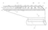
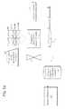
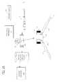
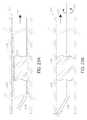
- FIG. 1is a side elevational schematic view of an intracranial aspiration catheter in accordance with the present invention, with a distal segment in a proximally retracted configuration.
- FIG. 2is a side elevational view as in FIG. 1 , with the distal segment in a distally extended configuration.
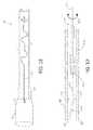
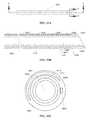
- FIGS. 3A-3Bare cross-sectional elevational views of a distal end of catheter 10 , with the distal section 34 fully extended.
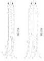
- FIGS. 4A-4Cschematically illustrate different cutting tip configurations.
- FIGS. 4D-4E and 4J-4Kschematically illustrate a distal dynamic funnel tip configuration.
- FIGS. 4F-4Gillustrate a dynamic flared tip having a first restraint system.
- FIGS. 4H-4Iillustrate a dynamic flared tip having an alternative restraint system.
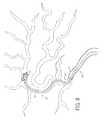
- FIG. 5depicts cerebral arterial vasculature including the Circle of Willis, and an access catheter positioned at an occlusion in the left carotid siphon artery.
- FIGS. 6 through 9show a sequence of steps involved in positioning of the catheter and aspirating obstructive material from the middle cerebral artery.
- FIG. 10illustrates removal of the catheter following aspiration of obstructive material.
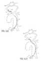
- FIGS. 11A-11Fdepict a sequence of steps to access a neurovascular occlusion for aspiration.
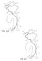
- FIGS. 12A-12Fdepict an alternative sequence of steps in accordance with an aspect of the present invention involved in accessing a neurovascular occlusion for aspiration.
- FIG. 13illustrates an aspiration system configured to apply pulsatile negative pressure through the aspiration catheter.
- FIG. 14illustrates an alternative aspiration system configured to apply pulsatile negative pressure through the aspiration catheter.
- FIG. 15illustrates a further alternative aspiration system configured to apply mechanical vibration through the aspiration catheter.
- FIGS. 16 and 17illustrate a further alternative aspiration system configured to apply mechanical vibration through the aspiration catheter.
- FIG. 18illustrates a further alternative aspiration system having an agitator configured to apply mechanical vibration at a vibration zone on the aspiration catheter.
- FIG. 19depicts a simplified agitator such as a hypo tube supported wire placed in a catheter to create a vibration zone.
- FIGS. 20A-20Cdepict agitators with various distal tip configurations.
- FIGS. 20D-20Edepict an agitator positioned within a swellable polymer distal funnel tip.
- FIGS. 21A-21Billustrate a moving or wiggling distal tip of a catheter in response to activating the agitator.
- FIGS. 22A-22Billustrate media injection from a moving or wiggling distal tip of an agitator.
- FIGS. 23A-23Billustrate media injection from a distal tip of an agitator to assist aspiration.
- FIG. 24depicts a proximal aspiration port carried by a catheter.
- FIGS. 25A-25Cdepict a pulsed aspiration cycle according to an embodiment.
- FIG. 26depicts a perspective view of a rotating hemostasis valve and a proximal drive assembly.
- FIG. 27Aillustrates a longitudinal cross-sectional elevational view taken along the line 27 A- 27 A in FIG. 26 .
- FIG. 27Billustrates an enlarged longitudinal cross-sectional elevational view of the proximal drive assembly 2602 from FIG. 27A .
- FIG. 28depicts a cross-sectional perspective view of the proximal portion of FIG. 26 .
- FIG. 29depicts a perspective view of an agitator driver, a proximal drive assembly, and a rotating hemostasis valve.
- FIG. 30illustrates a cross-sectional elevational view of a catheter wall according to an embodiment.
- FIG. 31Aillustrates a cross-sectional elevational view of a catheter wall according to another embodiment, showing one or more axially extending filaments.
- FIG. 31Bdescribes a side elevational view of the catheter of FIG. 31A
- FIG. 31Cillustrates a cross-sectional view taken along the line C-C of FIG. 31B , showing one or more axially extending filaments.
- FIG. 32Adepicts a side elevational view of a catheter according to one embodiment.
- FIG. 32Bdescribes a cross-sectional elevational view taken along the line A-A of FIG. 32A .
- FIG. 32Cillustrates a cross-sectional view taken along the line B-B of FIG. 32A .
- FIG. 33Adepicts a side elevational view of a catheter according to another embodiment.
- FIG. 33Bdescribes a cross-sectional elevational view taken along the line A-A of FIG. 33A , showing one or more axially extending filaments.
- FIG. 33Cillustrates a cross-sectional view taken along the line B-B of FIG. 33A , showing one or more axially extending filaments.
- FIG. 34Aillustrates a side elevational view of a progressively enhanced flexibility catheter according to an embodiment.
- FIG. 34Bis a proximal end view of the enhanced flexibility catheter of FIG. 34A .
- FIG. 35illustrates back-up support of the catheter in accordance with the present invention.
- FIG. 36depicts a graph of modulus or durometer of the catheter along the length of the catheter, from the proximal end to the distal end.
- FIG. 37depicts a graph of flexure test profiles of catheters in accordance with the present invention compared with conventional catheters.
- FIG. 38is a side elevational schematic view of a transformable catheter in accordance with the present invention.
- FIG. 39is a cross-sectional view taken along the lines 18 - 18 of FIG. 38 , showing heating elements within the catheter sidewall.
- catheter 10in accordance with one aspect of the present invention.
- catheters of the present inventioncan readily be modified to incorporate additional structures, such as permanent or removable column strength enhancing mandrels, two or more lumen such as to permit drug, contrast or irrigant infusion or to supply inflation media to an inflatable balloon carried by the catheter, or combinations of these features, as will be readily apparent to one of skill in the art in view of the disclosure herein.
- the present inventionwill be described primarily in the context of removing obstructive material from remote vasculature in the brain, but has applicability as an access catheter for delivery and removal of any of a variety of diagnostics or therapeutic devices with or without aspiration.
- catheters disclosed hereinmay readily be adapted for use throughout the body wherever it may be desirable to distally advance a low profile distal catheter segment from a larger diameter proximal segment.
- axially extendable catheter shafts in accordance with the present inventionmay be dimensioned for use throughout the coronary and peripheral vasculature, the gastrointestinal tract, the urethra, ureters, Fallopian tubes and other lumens and potential lumens, as well.
- the telescoping structure of the present inventionmay also be used to provide minimally invasive percutaneous tissue access, such as for diagnostic or therapeutic access to a solid tissue target (e.g., breast or liver or brain biopsy or tissue excision), delivery of laparoscopic tools or access to bones such as the spine for delivery of screws, bone cement or other tools or implants.
- a solid tissue targete.g., breast or liver or brain biopsy or tissue excision
- laparoscopic tools or access to bonessuch as the spine for delivery of screws, bone cement or other tools or implants.
- the catheter 10generally comprises an elongate tubular body 16 extending between a proximal end 12 and a distal functional end 14 .
- the length of the tubular body 16depends upon the desired application. For example, lengths in the area of from about 120 cm to about 140 cm or more are typical for use in femoral access percutaneous transluminal coronary applications. Intracranial or other applications may call for a different catheter shaft length depending upon the vascular access site, as will be understood in the art.
- the tubular body 16is divided into at least a fixed proximal section 33 and an axially extendable and retractable distal section 34 separated at a transition 32 .
- Distal segment 34extends between a proximal end 36 and a distal end 38 and defines at least one elongate central lumen 40 extending axially therethrough.
- Distal end 38may be provided with one or more movable side walls or jaws 39 , which move laterally in the direction of an opposing side wall or jaw 41 under the influence of aspiration, to enable the distal end 38 to bite or break thrombus or other material into smaller particles, to facilitate aspiration through lumen 40 .
- Both walls 39 and 41may be movable towards and away from each other to break up thrombus as is discussed further below.
- the proximal section 33may also or alternatively be provided with one or two opposing jaws, also responsive to vacuum or mechanical actuation to break up thrombus.
- the inner diameter of the distal section 34may be between about 0.030 inches and about 0.112 inches, between about 0.040 inches and about 0.102 inches, between about 0.045 inches and about 0.097 inches, between about 0.050 inches and about 0.092 inches, between about 0.055 inches and about 0.087 inches, between about 0.060 inches and about 0.082 inches, between about 0.062 inches and about 0.080 inches, between about 0.064 inches and about 0.078 inches, between about 0.066 inches and about 0.076 inches, between about 0.068 inches and about 0.074 inches, or between about 0.070 inches and about 0.072 inches.
- the inner diameter and the outer diameter of the distal section 34may be constant or substantially constant along its longitudinal length.
- the distal section 34may be tapered near its distal end.
- the distal section 34may be tapered at less than or equal to about 5 cm, about 10 cm, about 15 cm, about 20 cm, about 23 cm, about 25 cm, about 30 cm, about 31 cm, about 35 cm, about 40 cm, about 45 cm, about 50 cm, about 60 cm, or about 70 cm from its distal end.
- the inner diameter of the distal section 34may be tapered or decreased near the distal end by less than or equal to about 95%, about 90%, about 85%, about 80%, about 75%, about 70%, about 65%, about 60%, about 55%, about 50%, about 45%, about 40%, about 35%, about 30%, about 25%, about 20%, about 10%, or about 5%.
- the inner diameter of the distal section 34may be tapered or decreased near the distal end by greater than or equal to about 95%, about 90%, about 85%, about 80%, about 75%, about 70%, about 65%, about 60%, about 55%, about 50%, about 45%, about 40%, about 35%, about 30%, about 25%, about 20%, about 10%, or about 5%.
- the tapered inner diameter of the distal section 34may be by less than or equal to about 0.11 inches, about 0.1 inches, about 0.090 inches, about 0.080 inches, about 0.070 inches, about 0.065 inches, about 0.060 inches, about 0.055 inches, about 0.050 inches, about 0.045 inches, about 0.040 inches, about 0.035 inches, about 0.030 inches, about 0.025 inches, about 0.020 inches, about 0.015 inches, or about 0.010 inches.
- the length of the distal section 34may be between about 13 cm and about 53 cm, between about 18 cm and about 48 cm, between about 23 cm and about 43 cm, or between about 28 cm and about 38 cm.
- the length of the distal section 34may be less than or equal to about 20 cm, about 25 cm, about 30 cm, about 33 cm, about 35 cm, about 40 cm, about 41 cm, about 45 cm, about 50 cm, about 55 cm, about 60 cm, about 70 cm, or about 80 cm.
- the length of the distal section 34may depend on the degree of tapering of the internal diameter of the distal section 34 .
- the proximal end 36 of distal section 34is provided with a proximally extending pull wire 42 .
- Pull wire 42extends proximally throughout the length of the tubular body 16 , to control 24 which may be carried by manifold 18 .
- Axial movement of control 24produces a corresponding axial movement of distal section 34 with respect to proximal section 33 as has been discussed.
- the proximal end of pull wire 42may exit through a port on manifold 18 , such that it may be manually grasped and pulled or pushed by the clinician to extend or retract the distal section 34 .
- the length of the pull wire 42may be between about 700 mm and about 1556 mm, between about 800 mm and about 1456 mm, between about 850 mm and about 1406 mm, between about 900 mm and about 1356 mm, between about 950 mm and about 1306 mm, between about 1000 mm and about 1256 mm, between about 1020 mm and about 1236 mm, between about 1040 mm and about 1216 mm, between about 1060 mm and about 1196 mm, between about 1080 mm and about 1176 mm, between about 1100 mm and about 1156 mm, between about 1110 mm and about 1146 mm, or between about 1120 mm and about 1136 mm.
- an overlap 44Upon distal advance of pull wire 42 to its limit of travel, an overlap 44 remains between the proximal end 36 of distal section 34 and the proximal section 33 .
- This overlap 44is configured to provide a seal to enable efficient transmission of vacuum from proximal section 33 to distal section 34 .
- Overlap 44may be provided with any of a variety of additional features to facilitate a seal, such as a gasket, coating or tightly toleranced sliding fit.
- the clearance between the OD of the distal section 34 and ID of the proximal section 33at least in the vicinity of transition 32 , will be no more than about 0.005 inches and preferably no more than about 0.003 inches to provide an effective seal in a blood environment.
- the control 24is manipulated to distally advance distal section 34 deeper into the vasculature.
- the pull wire 42will be provided with sufficient column strength to enable distal advance of the distal tip 38 as will be discussed below.
- the pull wire 42 and distal section 34may be integrated into a catheter as illustrated in FIGS. 1 and 2 .
- distal section 34 and pull wire 42may be configured as a stand-alone catheter extension device as is discussed in greater detail below.
- the catheter extension devicemay be introduced into the proximal end of proximal section 33 after placement of proximal section 33 and advanced distally there through as illustrated in FIG. 3 A, to telescopically extend the reach of the aspiration system.
- the pull wire 42may comprise a tubular wall having an axially extending central lumen 45 .
- the central lumen 45permits introduction of media such as lubricants, drugs, contrast agents or others into the distal section 34 .
- the central lumen 45 extending through pull wire 42permits introduction of an agitator as is discussed in greater detail below.
- the distal tip 38may be provided any of a variety of structures which produce an active movement such as a biting action in response to the application of an activation force such as a vacuum in lumen 40 .
- an axially movable control wiremay be connected with respect to a side wall of the distal tip 38 , to enable cutting action under positive mechanical force.
- FIG. 4Aillustrates a distal tip 38 in an open configuration
- FIG. 4Billustrates distal tip 38 with opposing side walls 39 and 41 drawn together by the negative pressure in aspiration lumen 40 . This may be accomplished by providing a tapered thickness in side walls 39 and 41 , or a groove or living hinge which facilitates lateral movement of at least one of side wall 39 or 41 .
- a pivot point or hinge 43may be provided to enable lateral movement of side wall 39 to operate as a jaw.
- Two opposing side wallsmay be moveable medially and laterally with bilateral symmetry like a duck bill valve.
- Three or more jawsmay be provided, such as three triangular jaws separated at about 120° spacing which under an aspiration pulse close to form a pyramid closed tip.
- the distal tip 14is preferably provided with the capability to dilate beyond the nominal diameter of distal section 34 .
- Thisprovides a conical funnel like tip with an enlarged distal opening, to facilitate introduction of thrombotic material into the lumen 40 . See FIGS. 4D-4K .
- the diameter at the distal opening of the fully opened funnelexceeds the diameter of a cylindrical extension of the adjacent tubular body by at least about 10%, preferably at least about 25% or 45% or more.
- the flexible petalsmay be retained in a radially inwardly inclined configuration such as by application of negative pressure via lumen 40 during transluminal navigation of the distal section 34 .
- the panelsUpon removal of the negative pressure, the panels may incline radially outwardly in response to a preset bias. Application of pulsatile vacuum may thereafter cause the panels to close radially inwardly to perform the biting function described previously.
- the distal funnel openingmay be actuated in a variety of other ways as will be apparent to those of skill in the art, such as by providing a pull wire or axially slideable outer or inner sleeve to open and close the funnel in response to mechanical movement of the wire or sleeve.
- the funnel openingmay be controlled by rotation of a control wire or tubular sleeve relative to the distal section 34 , to activate an iris or spiral mechanism such as a helical ribbon or wire carried by the distal tip.
- the normal state of the distal funnelmay be a cylindrical configuration, and a mechanical, thermal or electrical actuator may be utilized to enlarge the distal funnel opening.
- the normal state of the funnelmay be conical, and a mechanical, thermal or electrical actuator may be utilized to reduce the diameter such as for transluminal navigation.
- the petals or other wall of the funnel or elements disposed within the wall of the funnelmay comprise a shape memory material such as a shape memory polymer or metal alloy such as nitinol, which may be laser cut from tube stock or woven into a fine mesh.
- the geometry of the funnelmay be transformed by application of heat, such as body heat, or heat from a heat source carried by the catheter such as an electrical resistance wire within the wall or adjacent the catheter tip.
- Heatmay alternatively be applied from a heat source introduced by way of central lumen 40 , such as a heated fluid, or a removable heater such as an elongate flexible body carrying a resistance coil. Transformation of the funnel from one configuration to the other may alternatively be accomplished by reducing the temperature of the funnel below body temperature such as by introducing a cooled fluid into thermal communication with the funnel tip or providing the catheter or a removable cooling catheter with a Joule-Thomson expansion chamber located near the distal end.
- a heat sourceintroduced by way of central lumen 40 , such as a heated fluid, or a removable heater such as an elongate flexible body carrying a resistance coil. Transformation of the funnel from one configuration to the other may alternatively be accomplished by reducing the temperature of the funnel below body temperature such as by introducing a cooled fluid into thermal communication with the funnel tip or providing the catheter or a removable cooling catheter with a Joule-Thomson expansion chamber located near the distal end.
- the sidewall of the funnelis provided with an inflatable balloon in the form of a ring or hoop, in communication with an inflation lumen extending throughout the length of the catheter.
- Introduction of inflation mediainflates the annular balloon, transforming the configuration of the funnel tip from a reduced diameter to an enlarged diameter.
- the distal tipis biased into the funnel configuration, and restrained into a cylindrical configuration such as for transluminal navigation.
- the restraintcan be removed.
- the restraintmay comprise an outer tubular covering membrane or loop configured to be removed by pulling a pull wire in a proximal direction.
- the restraintmay be a bioabsorbable material, which dissolves following a preset amount of time that exceeds the anticipated time from vascular access to reach the final intravascular position.
- the distal flared tipmay comprise embedded elastic elements (e.g., a coil, struts or cage) such as spring steel, Nitinol or others known in the art that bias the tip into the flared configuration.
- the elastic elementssuch as in the form of a Nitinol cage may alternatively reside on the ID of the catheter.
- the polymer tiprestrains the elastic elements to provide a cylindrical exterior configuration for transluminal navigation as seen in FIG. 4J .
- Softening the polymere.g., a hydrophilic blend
- body heat or moistureallows the elastic elements to transform the tip into the funnel configuration as seen in FIG. 4K .
- a conical NiTi cage at the tipis coated with a double hydrophilic non-cross linked glue.
- the polymer tipmay be formed without embedded elastic components and instead comprise a coextrusion with multiple layers, varying thickness in multiple layers, blending hydrophilic components at different ratios to control flaring.
- Multiple axially extending pull wiresmay be embedded through extruded lumen extending axially throughout the catheter wall. The wires are pushed or pulled to open/close the catheter distal end to flare or collapse. Funnel-shaped, underexpanded NiTi stent can be deployed at the tip area straddling between high and low durometer regions but greater length into high durometer region.
- the stentcan be pushed distally further into the low durometer tip. After complete clot retrieval the stent is pulled back into high durometer region, collapsing the funnel. This is an example of an active on-demand funneling tip.
- FIG. 4Fthere is illustrated a cross-sectional view of a distal end of a tubular catheter body such as distal section 34 .
- the tubular bodyis provided with a distal tip 38 in the form of a self expandable (e.g., NiTinol) mesh 50 , constrained by an outer tubular restraint 52 .
- Restraint 52may comprise a proximately retractable tubular body extending proximally to a control on the proximal manifold; a peel away sheath carried by an elongate proximally retractable pull wire, or other mechanism disclosed elsewhere herein. As shown in FIG.
- proximal retraction of tubular restraint 52 with respect to tubular body 34 , or distal advance of tubular body 34 with respect to restraint 52exposes and releases the mesh 50 to self expand to a funnel shape to facilitate capture and removal of intravascular debris.
- the self expandable conical mesh 50is restrained by interweaving an internal restraint wire 54 .
- Restraint wire 54may be a procedure guide wire, or a dedicated restraint wire. Proximal retraction of the restraint wire 54 releases the mesh 50 , to self expanded to a final, funnel configuration. Release of the mesh 50 may be accomplished in a variety of alternative ways, such as bio absorbable materials, and electrolytic detachment.
- the proximal end 12 of catheter 10is additionally provided with a manifold 18 having one or more access ports as is known in the art.
- manifold 18is provided with a proximal port such as a guidewire port 20 in an over-the-wire construction, and at least one side port such as aspiration port 22 .
- the aspiration port 22may be omitted if the procedure involves removal of the guidewire proximally from the guidewire port 20 following placement of the aspiration catheter, and aspiration through the guidewire port. Additional access ports and lumen may be provided as needed, depending upon the functional capabilities of the catheter.
- Manifold 18may be injection molded from any of a variety of medical grade plastics, or formed in accordance with other techniques known in the art.
- Manifold 18may additionally be provided with a control 24 , for controlling the axial position of the distal segment 34 of the catheter.
- Control 24may take any of a variety of forms depending upon the mechanical structure and desired axial range of travel of the distal segment 34 .
- control 24comprises a slider switch which is mechanically axially movably linked to the distal segment such that proximal retraction of the slider switch 24 produces a proximal movement of the distal segment 34 . This retracts the distal segment 34 into the proximal section 33 as illustrated in FIG. 1 .
- Distal axial advancement of the slider switch 24produces a distal axial advance of the distal segment 34 , as illustrated in FIGS. 2 and 3 .
- controlwill generally be linked to the distal segment by a control wire 42 .
- proximal section 33 and distal section 34may be provided as separate devices, in which construction the proximal control may be omitted.
- the distal end of proximal section 33may be provided with one or more jaws as has been discussed previously herein, for morcellating or otherwise breaking thrombus or other obstruction into pieces or otherwise facilitating aspiration.
- the proximal section 33may additionally be mechanically coupled to or adapted for coupling to a source of vibrational or rotational movement, such as to provide the intermittent or pulsatile movement discussed elsewhere herein to facilitate navigation into the vasculature.
- proximal section 33Using axial reciprocation, and/or rotation, and/or biting action of the distal jaws, the clinician may be able to reach the obstruction using proximal section 33 . See, for example, FIG. 5 in which proximal section 33 is able to reach an obstruction in the left carotid siphon. If, however, the proximal section 33 is not able to advance sufficiently close to the obstruction, a separate telescoping distal section 34 may be introduced into the proximal section 33 and advanced therethrough and beyond, as illustrated in FIGS. 2 and 6-10 , to reach the obstruction.
- the cerebral circulationis regulated in such a way that a constant total cerebral blood flow (CBF) is generally maintained under varying conditions.
- CBFtotal cerebral blood flow
- a reduction in flow to one part of the brainsuch as in acute ischemic stroke, may be compensated by an increase in flow to another part, so that CBF to any one region of the brain remains unchanged.
- the braincompensates by increasing blood flow to the ischemic area through its collateral circulation.
- FIG. 5depicts cerebral arterial vasculature including the Circle of Willis.
- Aorta 100gives rise to right brachiocephalic artery 82 , left common carotid artery (CCA) 80 , and left subclavian artery 84 .
- the brachiocephalic artery 82further branches into right common carotid artery 85 and right subclavian artery 83 .
- the left CCAgives rise to left internal carotid artery (ICA) 90 which becomes left middle cerebral artery (MCA) 97 and left anterior cerebral artery (ACA) 99 .
- ICAleft internal carotid artery
- MCAmiddle cerebral artery
- ACAleft anterior cerebral artery
- Anteriorly, the Circle of Willisis formed by the internal carotid arteries, the anterior cerebral arteries, and anterior communicating artery 91 which connects the two ACAs.
- the right and left ICAalso send right posterior communicating artery 72 and left posterior communicating artery 95 to connect, respectively, with right posterior cerebral artery (PCA) 74 and left PCA 94 .
- PCAright posterior cerebral artery
- the two posterior communicating arteries and PCAs, and the origin of the posterior cerebral artery from basilar artery 92complete the circle posteriorly.
- left carotid siphon 70When an occlusion occurs acutely, for example, in left carotid siphon 70 , as depicted in FIG. 5 , blood flow in the right cerebral arteries, left external carotid artery 78 , right vertebral artery 76 and left vertebral artery 77 increases, resulting in directional change of flow through the Circle of Willis to compensate for the sudden decrease of blood flow in the left carotid siphon. Specifically, blood flow reverses in right posterior communicating artery 72 , right PCA 74 , left posterior communicating artery 95 .
- Anterior communicating artery 91opens, reversing flow in left ACA 99 , and flow increases in the left external carotid artery, reversing flow along left ophthalmic artery 75 , all of which contribute to flow in left ICA 90 distal the occlusion to provide perfusion to the ischemic area distal to the occlusion.
- the proximal segment of catheter 10is transluminally navigated along or over the guidewire, to the proximal side of the occlusion.
- Transluminal navigationmay be accomplished with the distal section 34 of the catheter in the first, proximally retracted configuration. This enables distal advance of the proximal section 33 until further progress is inhibited by small and/or tortuous vasculature.
- the distal section 34is a separate device, and is not inserted into the proximal section 33 until it is determined that the proximal section 33 cannot safely reach the occlusion.
- the occlusionmay be safely reached by the proximal section 33 , without the need to insert or distally extend a distal section 34 .
- the distal end of the proximal section 33 of aspiration catheter 10is inserted typically through an incision on a peripheral artery over a guidewire and advanced as far as deemed safe into a more distal carotid or intracranial artery, such as the cervical carotid, terminal ICA, carotid siphon, MCA, or ACA.
- the occlusion sitecan be localized with cerebral angiogram or IVUS.
- the cathetercan be inserted directly into the symptomatic carotid artery after localization of the occlusion with the assistance of IVUS or standard carotid doppler and TCD.
- the distal section 34is inserted into the proximal port 20 and/or distally extended beyond proximal section 33 until distal tip 38 is positioned in the vicinity of the proximal edge of the obstruction.
- an obstruction 70is lodged in the middle cerebral artery 97 .
- Proximal section 33is positioned in the ICA and not able to navigate beyond a certain point such as at the branch 96 to the MCA artery 97 .
- the proximal section 33may be provided with a distal section 34 carried there in.
- a separate distal section 34may be introduced into the proximal end of proximal section 33 once the determination has been made that the obstruction 70 cannot be reached directly by proximal section 33 alone.
- the distal section 34may thereafter be transluminally navigated through the distal tortuous vasculature between proximal section 33 and the obstruction 70 .
- the obstruction 70may thereafter be drawn into distal section 34 upon application of constant or pulsatile negative pressure with or without the use of jaws or other activation on the distal end of distal section 34 as discussed elsewhere herein. Once the obstruction 70 has either been drawn into distal section 34 , or drawn sufficiently into distal section 34 that it may be proximately withdrawn from the body, proximal section 33 and distal section 34 are thereafter proximally withdrawn.
- Aspirationmay be applied via lumen 40 , either in a constant mode, or in a pulsatile mode.
- pulsatile application of vacuumwill cause the distal tip 38 to open and close like a jaw, which facilitates reshaping the thrombus or biting or nibbling the thrombus material into strands or pieces to facilitate proximal withdrawal under negative pressure through lumen 40 .
- Application of aspirationmay be accompanied by distal advance of the distal tip 38 into the thrombotic material.
- Pulsatile application of a vacuummay oscillate between positive vacuum and zero vacuum, or between a first lower negative pressure and a second higher negative pressure. Alternatively, a slight positive pressure may be alternated with a negative pressure, with the application of negative pressure dominating to provide a net aspiration through the lumen 40 . Pulse cycling is discussed in greater detail in connection with FIG. 25 .
- the proximal manifold and/or a proximal control unit (not illustrated) connected to the manifoldmay enable the clinician to adjust any of a variety of pulse parameters including pulse rate, pulse duration, timing between pulses as well as the intensity of the pulsatile vacuum.
- the distal sectionmay thereafter be proximally retracted into proximal section 33 and the catheter proximally retracted from the patient.
- proximal retraction of the catheter 10may be accomplished with the distal section 34 in the distally extended position.
- a vasodilatore.g., nifedipine or nitroprusside, may be injected through a second lumen to inhibit vascular spasm induced as a result of instrumentation.
- Pressuremay be monitored by a manometer carried by the catheter or a wire positioned in a lumen of the catheter.
- a pressure control and displaymay be included in the proximal control unit or proximal end of the catheter, allowing suction within the vessel to be regulated.
- Focal hypothermiawhich has been shown to be neuroprotective, can be administered by perfusing hypothermic oxygenated blood or fluid.
- Moderate hypothermiaat approximately 32 to 34° C., can be introduced during the fluid infusion.
- Perfusion through a port on manifold 18can be achieved by withdrawing venous blood from a peripheral vein and processing through a pump oxygenator, or by withdrawing oxygenated blood from a peripheral artery, such as a femoral artery, and pumping it back into the carotid artery.
- a thrombolytic agente.g., t-PA
- t-PAcan be infused through central lumen 40 or a second lumen to lyse any thrombotic material with greater local efficacy and fewer systemic complications.
- Administration of thrombolytic agentmay not be recommended for devices which are inserted directly into the carotid artery due to increased risk of hemorrhage.
- the intensity of intermittent or pulsatile vacuum applied to lumen 40may be adjusted to cause the distal tip 38 of the catheter 10 to experience an axial reciprocation or water hammer effect, which can further facilitate both translumenal navigation as well as dislodging or breaking up the obstruction.
- Water hammeror more generally fluid hammer, is a pressure surge or wave caused when a fluid in motion is forced to stop or change direction suddenly, creating a momentum change.
- a water hammercommonly occurs when a valve closes suddenly at the end of a pipeline system, and a pressure wave propagates in the pipe.
- a pressure surge or waveis generated inside the lumen 40 of the aspiration catheter 10 when a solenoid or valve closes and stops the fluid flow suddenly, or other pulse generator is activated.
- the catheter 10As the pressure wave propagates in the catheter 10 , it causes the catheter 10 to axially vibrate. Since vibration can reduce surface friction between the outer diameter of the catheter 10 and the inner diameter of the vessel wall, it enables catheter to track through tortuous anatomies as well as assist capturing thrombus.
- a thrombotic occlusion 1102is in the right middle cerebral artery (RMCA) 1104 .
- the RMCA 1104branches from the right internal carotid artery (RICA) 1106 .
- the RICA 1106branches from the right common carotid artery (RCCA) (not shown).
- the RICA 1106comprises cerebral 1108 (most distal from the aorta 100 ), cavernous 1110 , and petrous 1112 (most proximal from the aorta 100 ) segments.
- the RCCAbranches from the brachiocephalic artery.
- the brachiocephalic arterybranches from the arch 1114 of the aorta 100 .
- an introducer sheath 1120is introduced at the femoral artery 1118 .
- the outer diameter of the introducer sheath 1120may be equal to or less than about 12 F, 11 F, 10 F, 9 F, 8 F, 7 F, or 6 F.
- a guide sheath 1122is inserted through the introducer sheath 1120 .
- the outer diameter of the guide sheath 1122may be equal to or less than about 9 F, 8 F, 7 F, 6 F, 5 F, 4 F, or 3 F, and the inner diameter of the introducer sheath 1120 may be greater than the outer diameter of the guide sheath 1122 .
- an insert catheter 1124is inserted through the guide sheath 1122 .
- the outer diameter of the insert catheter 1124may be equal to or less than about 9 F, 8 F, 7 F, 6 F, 5 F, 4 F, or 3 F, and the inner diameter of the guide sheath 1122 may be greater than the outer diameter of the insert catheter 1124 .
- a first guidewire 1126may be introduced through the insert catheter 1124 (not shown in FIG. 11B ). Then, the guide sheath 1122 , the insert catheter 1124 , and optionally the first guidewire 1126 are tracked up to the aortic arch 1114 .
- the insert catheter 1124is used to engage the origin of a vessel. In FIG.
- the insert catheter 1124engages the origin 1116 of the brachiocephalic artery 82 .
- An angiographic runis performed by injecting contrast media through the insert catheter 1124 .
- the first guidewire 1126is removed prior to injecting the contrast media.
- the first guidewire 1126is inserted through the lumen of the insert catheter 1124 . Then, the first guidewire 1126 , the insert catheter 1124 , and the guide sheath 1122 are advanced together to the ICA 1106 .
- the most distal vessel that the guide sheath 1122 could navigate tois the petrous segment 1112 of the ICA 1106 .
- a second guidewire 1132 loaded inside the central lumen of a reperfusion catheter 1130(e.g., 3Max), which is loaded inside the central lumen of an aspiration catheter 1128 (e.g., ACE 68), are introduced through the guide sheath 1122 .
- the diameter of the second guidewire 1132may be equal to or less than about 0.03′′, about 0.025′′, about 0.02′′, about 0.016′′, about 0.014′′, about 0.01′′, or about 0.005′′.
- the inner diameter of the reperfusion catheter 1130may be greater than the outer diameter of the second guidewire 1132 .
- the inner diameter of the aspiration catheter 1128may be greater than the outer diameter of the reperfusion catheter 1130 .
- the inner diameter of the guide sheath 1122may be greater than the outer diameter of the aspiration catheter 1128 . Then, the second guidewire 1132 is advanced distally and positioned at the proximal end of the clot 1102 in the MCA 1104 .
- the aspiration catheter 1128is tracked over the reperfusion catheter 1130 and the second guidewire 1132 to the proximal end of the clot 1102 in the MCA 1104 . Both the second guidewire 1132 and the reperfusion catheter 1130 are removed. A vacuum pressure is then applied at the proximal end of the aspiration catheter 1128 to aspirate the clot 1102 through the central lumen of the aspiration catheter 1128 .
- a preferable, simplified method for aspirating a thrombotic occlusion in accordance with the present inventionis described in connection with FIGS. 12A-12F .
- the alternative steps for aspirating a thrombotic occlusionmake use of a transitional guidewire and a transitional guide sheath.
- the transitional guidewirehas a soft and trackable distal segment with a smaller diameter so that the transitional guidewire may be advanced deeper than the guidewire 1126 described in FIG. 11C .
- the transitional guide sheathhas a soft and trackable distal segment such that the transitional guide sheath may be advanced deeper than the guide sheath 1122 described in FIG. 11D .
- an introducer sheath 1220is introduced at the femoral artery 1218 .
- the outer diameter of the introducer sheath 1220may be equal to or less than about 12 F, 11 F, 10 F, 9 F, 8 F, 7 F, or 6 F.
- a transitional guide sheath 1222such as the combination access and aspiration catheter discussed in greater detail below is inserted through the introducer sheath 1120 at the femoral artery 1218 .
- the outer diameter of the guide sheath 1222may be equal to or less than about 9 F, 8 F, 7 F, 6 F, 5 F, 4 F, or 3 F. Referring to FIG.
- an insert catheter 1224is inserted through the transitional guide sheath 1222 .
- the outer diameter of the insert catheter 1224may be less than about 9 F, 8 F, 7 F, 6 F, 5 F, 4 F, or 3 F, and the inner diameter of the transitional guide sheath 1222 may be greater than the outer diameter of the insert catheter 1224 .
- a first guidewiremay be introduced through the insert catheter 1224 (not shown in FIG. 12B ).
- the diameter of the proximal section of the first guidewiremay be equal to or less than about 0.079′′, about 0.066′′, about 0.053′′, about 0.038′′, about 0.035′′, about 0.030′′, or about 0.013′′.
- the transitional guide sheath 1222 , the insert catheter 1224 , and optionally the first guidewireare tracked up to the aortic arch 1214 . See FIG. 12B .
- the insert catheter 1224may be used to select the origin of a vessel. In FIG. 12B , the insert catheter 1224 engages the origin 1216 of the brachiocephalic artery 82 .
- An angiographic runmay be performed by injecting contrast media through the insert catheter 1224 . In the cases where the first guidewire is used before the angiographic run, the first guidewire is preferably removed prior to injecting the contrast media.
- the transitional guidewire 1226is inserted through the lumen of the insert catheter 1224 or guide sheath 1222 .
- the diameter of at least a portion of the transitional guidewire 1226(e.g., proximal diameter) is substantially similar to that of the first guidewire 1126 .
- the diameter of at least a portion of the transitional guidewire 1226(e.g., distal diameter) may be smaller than that of the first guidewire 1126 and may have a diameter along a proximal segment of at least about 0.030′′ and in one implementation about 0.038′′.
- a transitionbegins within the range of from about 15 cm-30 cm from the distal end, and typically no more than about 20 cm or 25 cm from the distal end, distally of which the diameter tapers down to no more than about 0.018′′ and in one implementation about 0.016′′.
- the insert catheter 1224may be removed because it is too stiff to be advanced to the MCA 1204 .
- the transitional guidewire 1226provides sufficient back up support that the combination access and aspiration catheter 1224 may be advanced directly over the transitional guidewire without any intervening devices. Then, the transitional guidewire 1226 is advanced to the MCA 1204 .
- the transitional guidewire 1226has a distal segment that has a smaller diameter than that of the first guidewire 1126 described in FIG. 11C .
- the distal segment of the transitional guidewire 1226comprises a soft and atraumatic tip and can be tracked to the remote neurovasculature such as the MCA 1204 , which is distal to the petrous segment 1212 of the ICA 1206 .
- the transitional guide sheath 1222is advanced to or beyond the cavernous segment 1210 or the cerebral 1208 segment of the ICA 1206 .
- the transitional guide sheath 1222may be advanced to the cavernous segment 1210 or the cerebral 1208 segment of the ICA 1206 beyond the petrous segment 1212 because the transitional guide sheath 1222 has a soft yet trackable distal segment described in further detail below, for example in connection with FIG. 30 .
- the larger proximal diameter and stiffer body of the transitional guidewire 1226may provide better support for the transitional guide sheath 1222 to track through the vasculature.
- the transitional guidewire 1226is removed. Then, a vacuum pressure is applied at the proximal end of the transitional guide sheath 1222 to aspirate the clot 1202 through the central lumen of the transitional guide sheath 1222 .
- the inner diameter of the transitional guide sheath 1222may be equal to about or greater than about 0.100′′, about 0.088′′, about 0.080′′, about 0.070′′, or about 0.060′′.
- the inner diameter of the transitional guide sheath 1222is larger than the aspiration catheter 1128 described in FIG. 11E , which translates to more effective aspiration.
- the cross-sectional area of the central lumen of the transitional guide sheath 1222may be almost twice as large as that of the largest aspiration catheter 1128 currently available.
- a telescopic extension segmentas discussed elsewhere herein may be introduced into the proximal end of sheath 1222 and advanced distally to extend beyond the distal end of the sheath 1222 and thereby extend the reach of the aspiration system.
- the extension segmenthas an ID of about 0.070′′.
- pulsatile vacuummay be applied as discussed below. If pulsatile vacuum does not satisfactorily capture the clot, an agitator may be advanced through the sheath 1222 and extension segment to facilitate drawing the clot into the central lumen. Additional details of the agitator and its use are disclosed below.
- FIG. 13shows an embodiment of a pulsatile vacuum pressure aspirator 300 that applies intermittent or pulsatile vacuum to lumen 40 .
- the pulsatile vacuum pressure aspirator 300is in fluid connection with the proximal end 12 of the catheter 10 and comprises vacuum generator 302 , vacuum chamber 310 , collection canister 312 , solenoid valve 314 , frequency modulator 316 , valve controller 318 , and remote controller 320 .
- Vacuum generator 302comprises a vacuum pump 304 , a vacuum gauge 306 , and a pressure adjustment control 308 .
- the vacuum pump 304generates vacuum.
- the vacuum gauge 306is in fluid connection with the vacuum pump 304 and indicates the vacuum pressure generated by the pump 304 .
- the pressure adjustment control 308allows the user to set to a specific vacuum pressure. Any of a variety of controls may be utilized, including switches, buttons, levers, rotatable knobs, and others which will be apparent to those of skill in the art in view of the disclosure herein.
- Vacuum chamber 310is in fluid connection with the vacuum generator 302 and acts as a pressure reservoir and/or damper.
- Collection canister 312is in fluid connection with the vacuum chamber 310 and collects debris.
- the collection canister 312may be a removable vial that collects debris or tissues, which may be used for pathologic diagnosis.
- Vacuum chamber 310 and collection canister 312may be separate components that are in fluid connection with each other or a merged component. In the illustrated embodiment, the vacuum chamber 310 and the collection canister 312 is a merged component and is in fluid connection with the vacuum generator 302 .
- Solenoid valve 314is located in the fluid connection path between a luer or other connector configured to releasably connect to an access port of the catheter 10 and the vacuum chamber 310 /collection canister 312 .
- the solenoid valve 314controls the fluid flow from the catheter 10 to the vacuum chamber 310 /collection canister 312 .
- Pulsatile vacuum pressure aspirator 300may comprise frequency modulator 316 for control of the solenoid valve 314 .
- the frequency modulator 316generates different electrical wave frequencies and forms, which are translated into the movement of the solenoid valve 314 by the valve controller 318 .
- the wave forms generated from the frequency modulator 316comprise sinusoidal, square, and sawtooth waves.
- the wave forms generated from the frequency modulator 316typically have frequencies less than about 500 Hz, in some modes of operation less than about 20 Hz or less than about 5 Hz.
- the wave formshave duty cycles ranging from 0%, in which the solenoid valve 314 is fully shut, to 100%, in which the solenoid valve 314 is fully open.
- Valve controller 318modulates the solenoid valve 314 on and off.
- the valve controller 318may be electrically or mechanically connected to the solenoid valve 314 . Any of a variety of controls may be utilized, including electrical controllers, switches, buttons, levers, rotatable knobs, and others which will be apparent to those of skill in the art in view of the disclosure herein.
- the valve controller 318may be mechanically controlled by users or may be electrically controlled by the frequency modulator 316 .
- the frequency modulator 316 and the valve controller 318may be separate components that are electrically or mechanically connected or a merged component.
- Remote control 320enables physicians to control the frequency modulator 316 and/or the valve controller 318 for various purposes, such as turning the valve on/off, selecting different wave frequencies, and selecting different wave forms, while manipulating the catheter 10 at the patient side.
- Remote control 320may be in wired or wireless communication with aspirator 300 .
- the natural frequency of the catheteris typically less than about 260 Hz.
- the solenoid valve 414is positioned in and fluidly connects between the air/fluid reservoir 422 at the atmospheric pressure and the aspiration line 424 connecting the catheter 10 to the vacuum chamber 410 /collection canister 412 .
- this systemmodulates pressure in the catheter 10 by allowing pressure to vary from vacuum to atmospheric pressure.
- the solenoid valve 414is open to the air/fluid reservoir 422 at the atmospheric pressure, the vacuum pressure in the aspiration line 424 decreases to the atmospheric pressure.
- the solenoid valve 414is closed, it increases the vacuum pressure in the aspiration line 424 .
- an electro-magnetic actuated diaphragm 522is attached to the aspiration line 524 connecting the catheter 10 to the vacuum chamber 510 /collection canister 512 .
- the electromagnetic actuated diaphragm 522which is similar to that of a speaker driver, generates acoustic pressure waves in the catheter 10 .
- the diaphragm 522typically has a structure similar to a speaker driver and comprises frame 526 , cone 528 , dust cap 530 , surround 532 , spider or damper 534 , voice coil 536 and magnet 538 . Strength of the acoustic pressure waves may be modulated by the strength of the magnet 538 .
- the frequency modulator 516 connected to the remote control 520is electrically connected to the diaphragm 522 and generates different electrical wave frequencies and forms, which are translated by the diaphragm 522 into acoustic pressure waves in the aspiration line 524 and the catheter 10 .
- Tortuous vasculatureis a common reason for failure to treat vasculature occlusions in the body due to inability to track the catheter to the location of the disease. Navigating catheters through tortuous anatomy such as neurovasculature can be a challenge.
- the catheterhas to be very soft as not to damage the vessel wall. At the same time, it also has to be able to negotiate multiple tight turns without kinking. In addition, it has to have sufficient column strength to transmit force axially for advancing through the vasculature. All these performance characteristics are competing design requirements. It is difficult to optimize one performance characteristic without sacrificing the others.
- Reducing friction between the inner diameter of the vessel and the outer diameter of the cathetercan minimize axial force required to advance catheter through tortuous vasculature. Therefore, the column strength of the catheter may be traded off for optimizing other performance requirements of the catheter.
- An example of a method to reduce friction between the inner diameter of the blood vessel and the outer diameter of the catheteris to apply a thin layer of coating, usually hydrophilic in nature, to the outer diameter of the catheter to reduce its surface friction coefficient while in vivo.
- axial mechanical vibration or shock wavesmay be propagated to or generated at the distal end of the catheter using a variety of vibration generators, such as spark gap generators, piezoelectric pulse generators, electric solenoids, rotational shaft (wire) having one or more bends or carrying an eccentric weight, or any of a variety of other impulse generating sources well understood for example in the lithotripsy arts.
- vibration generatorssuch as spark gap generators, piezoelectric pulse generators, electric solenoids, rotational shaft (wire) having one or more bends or carrying an eccentric weight, or any of a variety of other impulse generating sources well understood for example in the lithotripsy arts.
- Mechanical shock wave or pulse generatorsmay be built into the proximal manifold 18 , and or mechanically coupled to the manifold or proximal catheter shaft as desired.
- controlsare provided on the manifold or on a proximal control coupled to the manifold, to enable the clinician to vary the intensity and time parameters of the mechanical pulses.
- Shock wavesmay be propagated along the proximal section 33 to assist in translumenal advance, and/or distal section 34 by way of pull wire 42 , depending upon the desired clinical performance.
- the distal end 608 of a vibrating device 600is placed in fluid connection with the proximal end 12 of the catheter 10 (not illustrated) and generates transverse and/or longitudinal vibration in the catheter 10 .
- transverse vibration in the catheter 10By inducing transverse vibration in the catheter 10 , it reduces effective contact surface area between the vessel and the catheter 10 , which in turn reduces surface friction force between the inner diameter of the vessel and the outer diameter of the catheter.
- the vibrating device 600breaks static friction between the inner diameter of the vessel and the outer diameter of the catheter 10 , which reduces overall surface friction. By reducing the friction between the inner diameter of the vessel and the outer diameter of the catheter 10 , the vibrating device 600 improves catheter trackability through tortuous vasculatures.
- the proximal end 602 of the vibrating device 600may be connected to a vacuum pressure source such as a vacuum generator.
- the proximal connector 604is attached to the housing 606 .
- the proximal connector 604may be a luer connector.
- the distal end 608 of the vibrating device 600is connected to the catheter 10 .
- the distal connector 610is held in place by a flexible seal 612 that is attached to the housing 606 .
- the distal connector 610may be a luer connector.
- the flexible seal 612allows the distal connector 610 to move longitudinally as well as transversely.
- the flexible tubinglinks the proximal connector 604 and the distal connector 610 , creating an aspiration channel 614 for the fluid to travel through.
- the vibrating devicehas a controller 616 to turn on/off the vibrating action as well as to vary its frequency.
- the controller 616is drawn as a sliding switch. Any of a variety of controls may be utilized, including electrical controllers, switches, buttons, levers, rotatable knobs, and others which will be apparent to those of skill in the art in view of the disclosure herein.
- a vibration generator such as a motor 618has an eccentrically mounted inertial weight on its shaft generating vibration. Any of a variety of motors may be used, including an electric motor, an electro-magnetic actuator, and a piezoelectric transducer. The frequency of the vibration is related to the RPM of the motor 618 .
- a driving circuit 620is connected to the motor 618 and the controller 616 and drives the motor 618 at different RPMs based on the manipulation of the controller 616 . In the illustrated embodiment, the circuit 620 drives the motor 618 at different RPMs based on the position of the sliding switch.
- a battery 622is connected to and powers the driving circuit 620 and the motor 618 .
- the motor 618may be mounted perpendicularly to the length of the aspiration channel 614 to create longitudinal vibration. Also, a mechanical cam may be attached to the motor 618 to create larger magnitude longitudinal reciprocating motion.
- the frequency range generated by the electric motoris typically less than about 85 Hz. To achieve sonic frequencies in the range from about 85 Hz to about 260 Hz, one might replace the electric motor with an electro-magnetic actuator. To achieve ultrasonic frequencies in the range of about 20 Hz to about 1.6 MHz, one might employ a piezoelectric transducer.
- an agitatorsuch as stylet 702 is permanently or removably inserted into a lumen 40 of the catheter 10 and rotated to generate vibration in the catheter 10 and thus improve catheter trackability through tortuous vasculatures.
- the stylet 702whose outer diameter is within the range of from about 0.005 inches (about 0.127 mm) to about 0.035 inches (about 0.889 mm), may have at least one bend or at least one weight. The peak to peak transverse distance between the bends will be less than the inner diameter of the catheter 10 when positioned within the catheter.
- the bends or weights of the stylet 702may be positioned at different locations along the entire length of the catheter 10 or contained within a vibration zone within the distal most 50% or 30% or 10% of the length of the catheter depending upon desired performance, with the purpose to create the most desirable vibration when tracking the catheter 10 through the distal vasculature.
- the stylet 702may have an asymmetric weight such as a bead at a distal vibration zone or at its distal end.
- the stylet 702may comprise a monofilament or braided or woven filaments or wires.
- the stylet 702may have a heater (e.g., an electric coil) at its distal end that facilitates the dissolution of the thrombus or changes the size of the thrombus that is aspirated into the catheter.
- a heatere.g., an electric coil
- the proximal end of the styletis attached to a motor driver 704 capable of generating rotational and or axially reciprocating motion at various frequencies to form a motor driver-stylet assembly 700 .
- the assembly 700has a controller 706 to turn on/off the rotating action as well as to vary its frequency.
- the controller 706is drawn as an on/off button. Any of a variety of controls may be utilized, including electrical controllers, switches, buttons, levers, rotatable knobs, and others which will be apparent to those of skill in the art in view of the disclosure herein.
- the proximal luer 708 or other connector of the catheter 10reversibly attaches the catheter 10 to the motor driver 804 .
- the entire motor driver-stylet assembly 700may be detached and removed from the catheter 10 leaving a central aspiration lumen.
- Emboli small enough to pass through the vertebral arteries into the larger basilar arteryare usually arrested at the top of the basilar artery, where it bifurcates into the posterior cerebral arteries.
- the resulting reduction in blood flow to the ascending reticular formation of the midbrain and thalamusproduces immediate loss of consciousness.
- the devices described hereincan be used to remove thromboembolic material from the vertebral artery or more distally such as in M1, M2, or M3 arteries.
- an agitator 1900may comprise an elongate, flexible body such as a wire or hypo tube having a proximal, control end and a distal, active zone or end.
- the hypo tube agitatorhas an inside lumen extending longitudinally that allows infusion of media.
- an agitator 1900comprises a wire or hypo tube 1904 , introduced into the proximal end of a catheter 1902 and advanced to the distal end 1907 of the catheter 1902 .
- the distal tip 1905 of the agitator 1900may be placed at, beyond, or inside the distal end of the catheter 1902 .
- the agitator 1900can be either preloaded into the catheter 1902 and inserted into the patient's body together with the catheter 1902 or added after the catheter 1902 has been placed.
- the agitator 1900may extend substantially longitudinally along the length of the catheter 1902 .
- the agitator 1900may further comprise a controller at the proximal end to axially adjust the distal tip position.
- the controller of the agitator 1900may be used to axially adjust the position of the distal tip 1905 when the agitator 1900 is introduced into a variable length catheter such as that discussed in connection with FIG. 3 .
- the agitator and drive systemare configured as a stand-alone device.
- the distal section 34FIG. 3B
- the distal end of agitator 1900maybe introduced into the proximal end of central lumen 45 of pull wire 42 .
- Agitator 1900may thereafter be distally advanced so that a distal segment of agitator 1900 extends beyond the distal end of pull wire 42 , and into the distal section 34 .
- the portion of the agitator 1900 contained within lumen 45 of pull wire 42is restrained from any significant lateral motion.
- agitator 1900which extends beyond the distal end of pull wire 42 is relatively laterally unconstrained and is able to agitate thrombus to facilitate drawing the thrombus into and through the distal section 34 .
- the agitator 1900may be rotated manually or via a motor 1906 driven from the catheter 1902 's proximal end to rotate or translate the distal end of the agitator 1900 .
- the driver 1906may be connected to the proximal end of the agitator 1900 either permanently or removably.
- the driver 1906may be a manual driver that is manually controlled such as a guidewire torquer.
- the driver 1906may be a motorized driver.
- the motorized drivermay be manually controlled with respect to one or more factors such as rotational direction (CCW/CW), speed, duration, etc.
- the motorized drivermay be automatically controlled with respect to one or more factors such as direction (CCW/CW), speed, duration, etc. In one mode, the rotational direction of the agitator is periodically reversed.
- the automatically controlled drivermay comprise an actuator, and actuating the actuator may execute a pre-programmed series of steps.
- the actuatormay be a button, a dial, a knob, a switch, a lever, a valve, a slide, a keypad, or any combinations thereof.
- the driver 1906may also be under synchronized control, in which the driver 1906 drives the agitator 1900 in synchronization with aspiration and media injection.
- the agitator 1900may be configured to promote motion at the distal end to help engage and move the clot.
- Mediamay be infused into/around the clot area to help liberate the clot from the vasculature.
- the agitator 1900comprises a distal end 1912 , a proximal end 1914 and a distal tip 1905 .
- the proximal end 1914 of the agitator 1900has a cross-section and/or wall thickness that is large enough to transmit the torque required to rotate the distal end 1912 of the agitator 1900 when placed in the catheter 1902 , within the curved vasculature.
- the outer diameter of the agitator 1900may be from about 0.25 mm to about 0.65 mm, from about 0.3 mm to about 0.6 mm, from about 0.35 mm to about 0.55 mm, from about 0.4 mm to about 0.5 mm, from about 0.42 mm to about 0.48 mm, or from about 0.44 mm to about 0.46 mm.
- the wall thickness of the hypo tube 1904may be from about 0.01 mm to about 0.29 mm, from about 0.05 mm to about 0.25 mm, from about 0.1 mm to about 0.2 mm, from about 0.12 mm to about 0.18 mm, from about 0.13 mm to about 0.17 mm, or from about 0.14 mm to about 0.16 mm.
- the agitator 1900may additionally be provided with a guide tube 1910 , such as a hypo tube, to allow the agitator to spin, or axially or rotationally reciprocate, while constraining a proximal drive segment of the agitator 1900 against lateral motion.
- a distal end 1911 of guide tube 1910may be positioned within about 25 cm or within about 20 cm or 15 cm or less of the distal end of the agitator 1900 , depending upon desired performance.
- the distal section of the agitator 1900extending beyond distal end 1911 of guide tube 1910 , is laterally unconstrained within the ID of distal segment 34 and available to agitate and facilitate aspiration of material into and through the central lumen.
- the diameter of the agitator 1900may be constant along its longitudinal length.
- the diameter of the agitator 1900may increase or decrease along its longitudinal length to coincide with features of the catheter 1902 .
- the diameter of the agitator 1900decreases in the distal direction along its longitudinal length by at least one step or tapered zone to provide increasing flexibility.
- the distal end 1912 of the agitator 1900may be straight. Alternatively, the distal end 1912 of the agitator 1900 may be curved or formed into different shapes to interact with the clot.
- FIG. 19illustrates a bend 1917 spaced apart from the distal tip 1905 by a motion segment 1909 having a length of from about 1 mm to about 15 mm.
- FIGS. 20A-20Cdepict more complex exemplary shapes of the motion segment 1909 of the agitator 1900 .
- FIGS. 20D-20Edepict an agitator positioned within a swellable polymer distal funnel tip.
- the agitator 1900may be comprise a single, uniform material or multiple materials.
- the materials of the agitator 1900may be processed (e.g., heat treatment/annealing) to give varying properties for the local performance requirements.
- the agitator 1900may be structured to provide flexibility while exhibiting high torque transmission.
- the agitator 1900may made of Nitinol, 304 Stainless Steel, 316 LVM Stainless Steel, PTFE, Parylene, or any combinations thereof. At least a portion of the surface of the agitator 1900 may be coated. The entire length of the agitator 1900 may be coated.
- the coating on the agitator 1900may provide lubrication between the ID wall of the catheter 1902 and the agitator 1900 .
- the coating on the agitator 1900may provide lubrication between the intermediate hypotube and the proximal drive portion of the agitator 1900 .
- the coating materials of the wire or hypo tube 1904include PTFE, Parylene, Teflon, or any combinations thereof.
- any of the ID or OD of any of the catheter shafts or other catheter components disclosed hereinmay be provided with a lubricious coating or may be made from a lubricious material.
- a hydrophilic polymersuch as Polyacrylamide, PEO, thermoplastic starch, PVP, copolymers of hydrophilic polymer can be extruded with hydrophobic polymers such as PEO soft segmented polyurethane blended with Tecoflex.
- the lubricious coating or the lubricious materialmay include surface modifying additive (SMA) during melt processing.
- SMAsurface modifying additive
- post processing wire ebeam, Gamma, UV, etc.additionally may be desirable to expose to moisture, temperature, etc.
- Cathetersmay be made from PEO impregnated polyurethanes such as Hydrothane, Tecophilic polyurethane for both OD and ID lubricity and inherent thromboresistant property without requiring a secondary coating process.
- the distal end 2012 of the agitator 1900may comprise a coil 2020 to grip a corked clot and wiggle the distal end 2010 of the catheter 2002 and the clot during rotation 2006 .
- the coil 2020may be a tight, offset coil, and may comprise at least one and optionally two or three or more complete revolutions.
- the distal end 2012 of the agitator 1900may comprise a hook 2022 to grip and emulsify a clot.
- the hook 2022may be concave proximally, or may extend transversely to the axis of the agitator body, extending in a circumferential orientation.
- the distal end 2012 of the agitator 1900may comprise a loose coil or spring 2024 .
- the loose coil or spring 2024may expand (lengthen) and contract (shorten) with a change in direction of rotation.
- the distal end 2012 of the agitator 2000may comprise a coil 2026 to grip a corked clot and wiggle the distal end 2010 of the catheter 2002 and the clot during rotation.
- the distal end 2010 of the catheter 2002may include a polymer sidewall that reforms by hydration.
- the coil 2026maintains a guide wire lumen during placement of the catheter.
- the polymerenables the distal end 2010 of the catheter 2002 to expand to a funnel shape after absorption of serum from blood. See FIG. 20E .
- the distal tip 2110 of the catheter 2102may move or wiggle by interacting with the agitator 1900 .
- the motion segment 1909 and distal tip 1905 of the agitatorinteract with the side wall of the catheter 2102 which wiggles as shown by broken lines 2112 .
- the length of the motion segment, stiffness of the agitator 1900 and rotational velocitydetermines the interaction with the wall of the catheter 2102 and the amount of wiggle transmitted to the catheter 2101 with rotation of the agitator 1900 .
- the distal tip 2110 of the catheter 2102may move or wiggle by pulsed media jets existing one or more holes near the distal end of the hypo tube 2124 .
- the hypo tube 2124has an inside lumen extending along the longitudinal length of the hypo tube 2124 .
- One or more side holes 2128may be placed near the distal end of the hypo tube 2124 and allow fluid communication between the lumen of the hypo tube 2124 and the outside of the hypo tube 2124 (i.e., the lumen of the catheter 2102 ).
- Mediae.g. saline
- pulsed media jetsWhen media is injected into the hypo tube 2124 in a pulsed manner, pulsed media jets eject from the holes of the hypo tube 2124 and transmit forces on the wall of the catheter 2102 , resulting in a wiggle motion of the catheter 2102 .
- the hypo tube 2124may additionally rotate (e.g., via a driver 2106 ) to facilitate a wiggle motion of the catheter 2102 .
- the hypo tube 2204may have one or more holes 2210 and is bent near its distal portion to provide a motion segment 1909 .
- Mediae.g. saline, a drug, a lubricant such as polyethylene glycol
- Vacuumis applied to the central lumen at the proximal end 2200 of the catheter 2202 such that media ejecting from the holes 2210 of the hypo tube 2204 is drawn proximally along the central lumen of the catheter 2202 toward its proximal end 2200 .
- the hypo tube 2204As the hypo tube 2204 rotates, the hypo tube 2204 ejects media and simultaneously makes the distal tip of the catheter 2202 wriggle.
- the wriggle of the catheter 2202may push the clot 2214 from side to side, and the hypo tube 2204 simultaneously ejects media at the interface between the clot 2214 and the catheter 2202 , providing a lubricious avenue for the clot 2214 to release and flow into the catheter 2202 .
- rotation of the motion segment 1909helps to break up or reshape the thrombus and facilitate entry into the aspiration lumen.
- the clotcan be aspirated completely within the central lumen.
- the clotmay only be able to be partially drawn into the central lumen, such as illustrated in FIG. 22B .
- rotation of the agitatormay be stopped with application of vacuum remaining on to retain the clot on the distal end of the catheter. The catheter may then be proximally withdrawn, pulling the clot along with it, into the access sheath and out of the proximal vascular access point.
- the hypo tube 2304may have one or more holes along its surface more proximal from the distal end to facilitate the movement or flow of the clot 2314 inside the catheter 2302 toward its proximal end 2300 .
- Vacuum 2316is applied at the proximal end 2300 of the catheter 2302 to move the removed clot 2314 from the distal end to the proximal end 2300 of the catheter 2302 .
- the holesmay provide a thin film 2312 around the inside of the wall of the catheter 2302 to facilitate the flow of media and/or the clot 2314 and minimize any clogging of the clot 2314 .
- FIG. 23Athe holes may provide a thin film 2312 around the inside of the wall of the catheter 2302 to facilitate the flow of media and/or the clot 2314 and minimize any clogging of the clot 2314 .
- the hypo tube 2304may have one or more holes to provide media jets ejecting radially from the hypo tube 2304 to grab, pull, and/or emulsify the clot 2314 as the clot 2314 passes by the one or more holes on the surface of the hypo tube 2304 .
- a vacuum port 2416may be provided near the proximal end 2400 of the catheter 2402 such as on the manifold for releasable connection to a vacuum source to aspirate the clot from the vasculature. This allows the vacuum port 2416 to be distinct from the proximal port 2417 for receiving the agitator 1900 . This can minimize the risk that the movement or control of the wire or hypo tube 2404 at its proximal end may be adversely affected by vacuum, aspirated clot, and/or media.
- the vacuum portmay be connected to the catheter 2400 via a rotating hemostasis valve, discussed below.
- an interrupted vacuumcan help aspirating a corked clot stuck at the distal end 2512 of the catheter 2510 by loosening the clot and reshaping it to fit into the catheter 2510 after each vacuum and release cycle.
- Merely stopping the vacuumis not sufficient to loosen the clot.
- Completely releasing (venting to atmospheric pressure) the vacuum and allowing the clot to relax before reapplying a vacuumis found to aspirate the corked clot most efficiently.
- the period of each vacuum and release cyclemay be equal to or greater than about 0.1, 0.5, 1, 2, 3, 4, 5, 6, 7, 8, 9, or 10 seconds.
- FIGS. 25A-25Cshow a logical progression of the vacuum and release cycle as applied to the catheter 2510 .
- a release line 2518 and a vacuum line 2520are connected to or near the proximal end of the catheter 2510 .
- the release line 2518is in communication with atmospheric pressure on its proximal end and has a release valve 2514 configured to open or close the fluid communication between the catheter 2510 and the vacuum.
- the vacuum line 2520is connected to vacuum on its proximal end and has a vacuum valve 2516 configured to open or close the fluid communication between the catheter 2510 and the vacuum.
- the release valve 2514is closed, and the vacuum valve 2516 is open such that the vacuum is applied to the catheter 2510 to aspirate the clot.
- the release valve 2514is opened while the vacuum valve 2516 stays open. Because the release line 2518 and the vacuum line 2520 are in fluid communication, either directly or via at least a portion of the catheter 2510 , the vacuum is applied mainly through the release line 2518 , dropping vacuum applied to the catheter.
- the vacuum valve 2516is shut off, allowing the vacuum to be completely released and the clot to relax. Then, another cycle from FIG. 25A to FIG. 25C begins by closing the release valve 2514 and opening the vacuum valve 2516 .
- a proximal drive assembly and/or the rotating hemostasis valveto provide the interface for driving the agitator 1900 , providing the port for injecting media, and the aspiration port.
- the proximal drive assembly 2602 and the rotating hemostasis valve 2620may be releasably or permanently coupled to the proximal end of the agitator 1900 .
- the proximal portion of the agitator 1900passes proximally through a lumen of the rotating hemostasis valve 2620 and then that of the proximal drive assembly 2602 .
- the proximal end of the agitator 1900may terminate inside the lumen of the proximal drive assembly 2602 .
- the distal portion of the proximal drive assembly 2602is inserted into the proximal end of the rotating hemostasis valve 2620 .
- the proximal drive assembly 2602may be integrated into the rotating hemostasis valve 2620 .
- the rotating hemostasis valve (RHV) 2620comprises a distal connector 2630 at its distal end, which is configured to couple the rotating hemostasis valve to the proximal end of the catheter (not shown).
- the distal connector 2630may be a luer connector.
- the rotating hemostasis valve 2620comprises a central lumen along its longitudinal length, through which a proximal section of agitator 1900 passes.
- the rotating hemostasis valve 2620further comprises an aspiration port 2622 , which bifurcates from the central lumen of the rotating hemostasis valve 2620 and provides the aspiration flow path.
- the rotating hemostasis valve 2620comprises a RHV seal 2626 and a proximal rotating collar 2628 at its proximal end.
- the proximal rotating collar 2628controls the opening and closing of the RHV seal 2626 .
- the usere.g., physician
- the RHV seal 2626when closed, does not allow fluid communication between the inside lumen distal of the RHV seal 262 and the inside lumen proximal of the RHV seal 262 .
- the RHV seal 262does not hamper the longitudinal movement of the distal portion of the proximal drive assembly 2602 inside the rotating hemostasis valve 2629 .
- the distal end of the agitator 1900changes its position relative to the catheter.
- the distal end of the agitator 1900was shown to foreshorten/lengthen as the wire or hypo tube 2624 wound/unwound within the catheter due to the rotation of the agitator 1900 or the increase/decrease in media injection pressure.
- the proximal rotating collar 2628 and the RHV seal 2626permit the user (e.g., physician) to account for this variance in length and advance/withdraw the agitator 1900 relative to the catheter and fix it in place by simply moving the proximal drive assembly 2602 in/out of the rotating hemostasis valve 2629 . If the agitator 1900 is preloaded into the catheter, the distance may be initially set at a nominal position.
- the proximal rotating collar 2628 of the rotating hemostasis valve 2620may be part of the proximal drive assembly 2602 .
- the proximal drive assembly 2602comprises a proximal drive connector 2604 , to which the driver is connected, and a media injection port 2610 , into which media is injected.
- the proximal drive assemblyalso comprises a bearing 2606 , which allows free rotation of the proximal drive connector 2604 with respect to the proximal drive assembly 2602 .
- the proximal drive connection 2604may be coupled to the proximal end of the agitator 1900 such that the rotation of the proximal drive connector 2604 is translated to the rotation of the wire or hypo tube 1900 .
- the proximal drive assemblyfurther comprises a drive tube seal 2608 , which prevents fluid communication between the inside lumen (of the proximal drive assembly 2602 ) distal of the drive tube seal 2608 and the inside lumen proximal of the drive tube seal 2608 .
- the driver 2950is removably connected to the proximal end of the proximal drive assembly 2902 via the proximal drive connection 2604 .
- the driver 2950is configured to drive the agitator 1900 .
- the driver 2950is a motorized driver that is automatically controlled with respect to one or more factors such as direction (CCW/CW), speed, duration, etc.
- the driver 2950comprises a control 2954 such as a button, which executes a pre-programmed series of steps when pushed.
- the driver 2954may be under synchronized control, in which the driver 2954 drives the agitator 1900 in synchronization with aspiration and media injection, when the back of the driver 2950 is plugged into the synchronization port 2952 .
- the system for retrieving clotscomprises the aspiration catheter; the agitator 1900 longitudinally extendable inside the lumen of the aspiration catheter; and the driver connectable to the proximal end of the agitator 1900 (e.g., via the rotating hemostasis valve or the proximal drive assembly) with or without a synchronization port.
- the systemmay allow impulse aspiration and/or impulse injection of media.
- the mediamay comprise water, saline solution, or media with an effective amount of drug (e.g., drug therapy such as heparin, plavix, tPA).
- the componentsmay be manipulated individually or in a synchronized manner using predetermined operating parameters (e.g., for synchronized aspiration, injection, and rotation).
- the method of retrieving a clotmay comprise providing the aspiration catheter, the agitator longitudinally extending or positionable inside the lumen of the aspiration catheter; and the driver coupled to the proximal end of the agitator; placing the catheter adjacent to the clot; attempting to aspirate clot; if not successful, advancing an agitator distally through the catheter; activating the driver to rotate the agitator and loosen the clot; optionally injecting media through the agitator to lubricate the clot and/or create a media jet from the distal end of the agitator, configured to help aspirate the clot; transporting the clot proximally inside the lumen of the catheter by applying the vacuum at the proximal end of the catheter; and optionally pulsing the vacuum. As pieces of the clot separate, transport may be assisted by the rotating agitator and/or injection media.
- aspiration, media injection, and/or rotation of the wire or hypo tubemay be timed. Building up a surplus of media around the clot will form a plug.
- aspirationis activated and/or pulsed, the vacuum can draw the “plug” proximally inside the lumen of the wire or hypo tube like a syringe plunger. A higher local vacuum around the clot is maintained, and more momentum is added to the “plug” as more media is added. Timing the rotation of the wire or hypo tube with aspiration and media injection may help wiggle or fatigue the clot and detach it out of the vasculature.
- any of the catheter shaft or sections of the catheter shaft or telescoping extensions in accordance with the present inventionmay comprise a multi-layer construct having a high degree of flexibility and sufficient push ability to reach deep into the cerebral vasculature, such as at least as deep as the petrous, cavernous, or cerebral segment of the internal carotid artery (ICA).
- ICAinternal carotid artery
- the catheter 3000may have an effective length from the manifold to distal tip from about 70 cm to about 150 cm, from about 80 cm to about 140 cm, from about 90 cm to about 130 cm, from about 100 cm to about 120 cm, or from about 105 cm to about 115 cm.
- the outer diameter of the catheter 3000may be from about 0.07 inches to about 0.15 inches, from about 0.08 inches to about 0.14 inches, from about 0.09 inches to about 0.13 inches, from about 0.1 inches to about 0.12 inches, or from about 0.105 inches to about 0.115 inches, and may be lower in a distal segment than in a proximal segment.
- the inner diameter 3108 of the catheter 3000 in a single central lumen embodimentmay be greater than or equal to about 0.11 inches, greater than or equal to about 0.1 inches, greater than or equal to about 0.09 inches, greater than or equal to about 0.088 inches, greater than or equal to about 0.08 inches, greater than or equal to about 0.07 inches, greater than or equal to about 0.06 inches, or greater than or equal to about 0.05 inches.
- the inner diameter 3108 of the catheter 3000 in a single central lumen embodimentmay be less than or equal to about 0.11 inches, less than or equal to about 0.1 inches, less than or equal to about 0.09 inches, less than or equal to about 0.088 inches, less than or equal to about 0.08 inches, less than or equal to about 0.07 inches, less than or equal to about 0.06 inches, or less than or equal to about 0.05 inches.
- an inner liner 3014may be formed by dip coating a mandrel (not shown) to provide a thin walled tubular inside layer of the catheter body 3000 .
- the dip coatingmay be produced by coating a wire such as a silver coated copper wire in PTFE.
- the mandrelmay thereafter be axially elongated to reduce diameter, and removed to leave the tubular inner liner.
- the outside surface of the tubular inner liner 3014may thereafter be coated with a soft tie layer 3012 such as polyurethane (e.g., TecoflexTM), to produce a layer having a thickness of no more than about 0.005 inches, and in some implementations approximately 0.001 inches.
- the tie layer 3012will generally extend along at least about the most distal 10 cm or 20 cm of the catheter shaft 3000 generally less than about 50 cm and may in one implementation extend approximately the distal 30 cm of the catheter shaft 3000 , 3100 .
- a braid such as a 75 ppi stainless steel braid 3010may thereafter be wrapped around the inner liner 3014 through a proximal zone up to a distal transition 3011 .
- a coil 3024comprising a shape memory material such as a Nitinol alloy may thereafter be wrapped around the inner liner 3014 .
- the Nitinol coilhas a transition temperature below body temperature so that the Nitinol reside in the austinsite (springy) state at body temperature. Adjacent loops or filars of the coil may be closely tightly wound in a proximal zone with a distal section having looser spacing between adjacent loops.
- At least the distal 1 or 2 or 3 or 4 cm of the coilwill have a spacing that is at least about 130%, and in some implementations at least about 150% or more than the spacing in the proximal coil section.
- the spacing in the proximal coilmay be about 0.004 inches and in the distal section may be at least about 0.006 inches or 0.007 inches or more.
- the distal end of the coil 3024is spaced proximally from the distal end of the inner liner 3014 to provide room for an annular radiopaque marker 3040 .
- the distal end of the catheter 3000is provided with a beveled distal surface 3006 residing on a plane having an angle of at least about 10° or 20° and in one embodiment about 30° with respect to a longitudinal axis of the catheter 3000 .
- the radiopaque marker 3040may reside in a plane that is transverse to the longitudinal axis.
- at least the distally facing edge of the annular radiopaque marker 3040may be an ellipse, residing on a plane which is inclined with respect to the longitudinal axis to complement the bevel angle of the distal surface 3006 .
- an outer Jacket 3020maybe applied such as a shrink wrap tube to enclose the catheter body 3000 .
- the outer shrink-wrapped sleeve 3020may comprise any of a variety of materials, such as polyethylene, polyurethane, PEBAX, nylon or others known in the art. Sufficient heat is applied to cause the polymer to flow into and embed the proximal braid and distal coil.
- the outer shrink wrap jacket 3020is formed by sequentially advancing a plurality of short tubular segments 3022 , 3026 , 3028 , 3030 , 3032 , 3034 , 3036 , 3038 concentrically over the catheter shaft subassembly, and applying heat to shrink the sections on to the catheter 3000 and provide a smooth continuous outer tubular body.
- the foregoing constructionmay extend a long at least the most distal 10 cm, and preferably at least about the most distal 20 or 25 cm of the catheter body 3000 .
- the durometer of the outer wall segmentsmay decrease in a distal direction.
- proximal segmentssuch as 3022 and 3026
- proximal segmentssuch as 3022 and 3026
- a 25 cm sectionmay have at least about 3 or 5 or 7 or more segments and the catheter 3000 overall may have at least about 6 or 8 or 10 or more distinct flexibility zones.
- the distal 1 or 2 or 4 or more segments 3036 , 3038may have a smaller OD following shrinking than the more proximal segments 3022 - 3034 to produce a step down in OD for the finished catheter body 3000 .
- the length of the lower OD section 3004may be within the range of from about 3 cm to about 15 cm and in some embodiments is within the range of from about 5 cm to about 10 cm such as about 7 or 8 cm, and may be accomplished by providing the distal segments 3036 , 3038 with a lower wall thickness.
- the cathetermay further comprise a tension support for increasing the tension resistance in the distal zone.
- the tension supportmay comprise a filament and, more specifically, may comprise one or more axially extending filaments 3042 .
- the one or more axially extending filaments 3042may be axially placed inside the catheter wall near the distal end of the catheter.
- the one or more axially extending filaments 3042serve as a tension support and resist elongation of the catheter wall under tension (e.g., when the catheter is being proximally retracted through tortuous vasculature).
- At least one of the one or more axially extending filaments 3042may proximally extend along the length of the catheter wall from near the distal end of the catheter to less than about 5 cm from the distal end of the catheter, less than about 10 cm from the distal end of the catheter, less than about 15 cm from the distal end of the catheter, less than about 20 cm from the distal end of the catheter, less than about 25 cm from the distal end of the catheter, less than about 30 cm from the distal end of the catheter, less than about 35 cm from the distal end of the catheter, less than about 40 cm from the distal end of the catheter, or less than about 50 cm from the distal end of the catheter.
- the one or more axially extending filaments 3042may have a length greater than or equal to about 50 cm, greater than or equal to about 40 cm, greater than or equal to about 35 cm, greater than or equal to about 30 cm, greater than or equal to about 25 cm, greater than or equal to about 20 cm, greater than or equal to about 15 cm, greater than or equal to about 10 cm, or greater than or equal to about 5 cm.
- At least one of the one or more axially extending filaments 3042may have a length less than or equal to about 50 cm, less than or equal to about 40 cm, less than or equal to about 35 cm, less than or equal to about 30 cm, less than or equal to about 25 cm, less than or equal to about 20 cm, less than or equal to about 15 cm, less than or equal to about 10 cm, or less than or equal to about 5 cm.
- At least one of the one or more axially extending filaments 3042may extend at least about the most distal 50 cm of the length of the catheter, at least about the most distal 40 cm of the length of the catheter, at least about the most distal 35 cm of the length of the catheter, at least about the most distal 30 cm of the length of the catheter, at least about the most distal 25 cm of the length of the catheter, at least about the most distal 20 cm of the length of the catheter, at least about the most distal 15 cm of the length of the catheter, at least about the most distal 10 cm of the length of the catheter, or at least about the most distal 5 cm of the length of the catheter.
- the one or more axially extending filaments 3042may be placed near or radially outside the tie layer 3012 or the inner liner 3014 .
- the one or more axially extending filaments 3042may be placed near or radially inside the braid 3010 and/or the coil 3024 .
- the one or more axially extending filaments 3042may be carried between the inner liner 3014 and the helical coil 3024 .
- the axially extending filaments 3042may be placed in a radially symmetrical manner.
- the angle between the two axially extending filaments 3042 with respect to the radial center of the cathetermay be about 180 degree.
- the axially extending filaments 3042may be placed in a radially asymmetrical manner.
- the angle between any two axially extending filaments 3042 with respect to the radial center of the cathetermay be less than about 180 degree, less than or equal to about 165 degree, less than or equal to about 150 degree, less than or equal to about 135 degree, less than or equal to about 120 degree, less than or equal to about 105 degree, less than or equal to about 90 degree, less than or equal to about 75 degree, less than or equal to about 60 degree, less than or equal to about 45 degree, less than or equal to about 30 degree, less than or equal to about 15 degree, less than or equal to about 10 degree, or less than or equal to about 5 degree.
- the one or more axially extending filaments 3042may be made of materials such as Kevlar, Polyester, Meta-Para-Aramide, or any combinations thereof. At least one of the one or more axially extending filaments 3042 may comprise a single fiber or a multi-fiber bundle, and the fiber or bundle may have a round or rectangular cross section.
- the terms fiber or filamentdo not convey composition, and they may comprise any of a variety of high tensile strength polymers, metals or alloys depending upon design considerations such as the desired tensile failure limit and wall thickness.
- the cross-sectional dimension of the one or more axially extending filaments 3042may be no more than about 1%, 2%, 3%, 4%, 5%, 6%, 7%, 8%, 9%, 10%, 11%, 12%, 13%, 14%, 15%, 20%, 25%, or 30% of that of the catheter 3000 .
- the cross-sectional dimension of the one or more axially extending filaments 3042may be no more than about 0.001 inches, about 0.002 inches, about 0.003 inches, about 0.004 inches, about 0.005 inches, about 0.006 inches, about 0.007 inches, about 0.008 inches, about 0.009 inches, about 0.010 inches, about 0.015 inches, about 0.020 inches, about 0.025 inches, or about 0.030 inches.
- the one or more axially extending filaments 3042may increase the tensile strength of the distal zone of the catheter to at least about 1 pound, at least about 2 pounds, at least about 3 pounds, at least about 4 pounds, at least about 5 pounds, at least about 6 pounds, at least about 7 pounds, at least about 8 pounds, or at least about 10 pounds or more.
- an intraluminal catheter 3200such as a telescopic extension segment having a proximally extending control wire as has been described elsewhere herein (e.g., distal segment 34 in FIGS. 3A and 3B ) may be inserted through the catheter 3000 from the proximal end of the catheter 3000 .
- the intraluminal catheter 3200is inserted such that the distal end of the intraluminal catheter 3200 reaches further distally beyond the distal end of the catheter 3000 .
- the outer diameter of the intraluminal catheter 3200is smaller than the inner diameter of the catheter 3000 . This way, the intraluminal catheter 3200 can slide inside the lumen of the catheter 3000 .
- the intraluminal catheter 3200incorporates characteristics of the side wall construction of the catheter 3000 described herein.
- the axial length of the tubular extension segmentmay be less than about 50% and typically less than about 25% of the length of the catheter 3000 .
- the axial length of the tubular extension segmentwill generally be at least about 10 cm or 15 cm or 20 cm or 25 cm or more but generally no more than about 70 cm or 50 cm or 30 cm.
- the intraluminal catheter 3200may have one or more axially extending filaments 3242 .
- the one or more axially extending filaments 3242incorporate characteristics of the one or more axially extending filaments 3042 of the catheter 3000 , except the cross-sectional dimension as measured in the radial direction of the one or more axially extending filaments 3242 of the intraluminal catheter 3200 may be less than the corresponding dimension of the filament 3042 in the catheter 3000 .
- a distal segment 3038may have a length within the range of about 1-3 cm, and a durometer of less than about 35D or 30D.
- An adjacent proximal segment 3036may have a length within the range of about 4-6 cm, and a durometer of less than about 35 D or 30 D.
- An adjacent proximal segment 3034may have a length within the range of about 4-6 cm, and a durometer of about 35 D or less.
- An adjacent proximal segment 3032may have a length within the range of about 1-3 cm, and a durometer within the range of from about 35 D to about 45 D (e.g., 40 D).
- An adjacent proximal segment 3030may have a length within the range of about 1-3 cm, and a durometer within the range of from about 50 D to about 60 D (e.g., about 55 D).
- An adjacent proximal segment 3028may have a length within the range of about 1-3 cm, and a durometer within the range of from about 35 D to about 50 D to about 60 D (e.g., about 55 D).
- An adjacent proximal segment 3026may have a length within the range of about 1-3 cm, and a durometer of at least about 60 D and typically less than about 75 D. More proximal segments may have a durometer of at least about 65 D or 70 D.
- the distal most two or three segmentsmay comprise a material such as Tecothane, and more proximal segments may comprise PEBAX or other catheter jacket materials known in the art.
- At least three or five or seven or nine or more discrete segmentsmay be utilized, having a change in durometer between highest and lowest along the length of the catheter shaft of at least about 10 D, preferably at least about 20 D and in some implementations at least about 30 D or 40 D or more.
- Performance metrics of a catheterinclude back-up support, trackability, pushability, and kink resistance.
- Back-up supportmeans ability of the catheter to remain in position within anatomy and provide a stable platform through which endoluminal devices may advance. Referring to FIG. 35 , when the devices are pushed through the catheter 3202 , if there is not enough back-up support in the catheter 3202 , the distal portion 3204 of the catheter 3202 may prolapse, pull out, or back out of a vessel 3206 that branches out of a main blood vessel (e.g., brachiocephalic artery 82 , common carotid artery 80 , or subclavian artery 84 ).
- a main blood vessele.g., brachiocephalic artery 82 , common carotid artery 80 , or subclavian artery 84 .
- Back-up support for the catheter 3202may be improved by providing a proximal region with high durometer or modulus and a distal region with low durometer or modulus.
- Durometer or modulus of the proximal region of the catheter 3202may be improved by braid reinforcement.
- the region of the catheter at which durometer or modulus is strengthenedmay be placed near branching points at which the aortic arch 1114 , 1214 branches into brachiocephalic artery 82 , common carotid artery 80 , or subclavian artery 84 or near other anatomical structures (i.e., branching points) at which a main vessel branches into one or more smaller vessels, providing an opportunity for a catheter with poor back-up support to prolapse.
- the region of the catheter at which durometer or modulus is strengthenedmay be placed within about 0.5 cm, about 1 cm, about 2 cm, about 3 cm, about 4 cm, about 5 cm, or about 6 cm from a branching point at which a main vessel branches into one or more smaller vessels.
- Trackabilitymeans ability of the catheter to track further distally than other catheters (e.g., to M1).
- a catheter that can reach a cerebral segment of the internal carotid artery (ICA)has better trackability than a catheter that can reach a cavernous or petrous segment of the ICA.
- Trackability of the cathetermay be improved by using a catheter wall with low durometer or modulus or by adding a coating (e.g., a hydrophilic coating) on at least a portion of the catheter wall.
- the hydrophilic coatingmay be placed along the distal most region of the catheter.
- the hydrophilic coating on the cathetermay extend to about 1 cm, about 5 cm, about 10 cm, about 15 cm, or about 20 cm from the distal end of the catheter.
- the region with lower durometer or modulusmay locate at the distal most region of the catheter.
- the region with lower durometer or modulusmay extend to about 1 cm, about 5 cm, about 10 cm, about 15 cm, or about 20 cm from the distal end of the
- Pushabilitymeans rigidity of the catheter sufficient to push through anatomy without “buckling”.
- Pushability of the cathetermay be improved by increasing its durometer or modulus.
- Pushability of the cathetermay also be improved by providing a proximal region with high durometer or modulus and a distal region with low durometer or modulus.
- a transition region of the catheter in which durometer or modulus changes along its longitudinal lengthmay begin at about 50%, 60%, 70%, 75%, 80%, or more of the length of the catheter from its proximal end.
- Kink resistancemeans resistance of the catheter to kinking. In addition, if the catheter does kink, kink resistance of the catheter helps it return to its original shape. Kink resistance is important in the distal segment of the catheter, which is more prone to kinking than the proximal segment. Kink resistance of the catheter may be improved by adding one or more NiTi coils (or a coil at least portion of which is Nitinol) to the catheter wall.
- the catheter according to an embodimentmay have a decreasing durometer or modulus (E) approaching its distal end.
- the proximal end of the catheterhas higher durometer or modulus than that of the distal end of the catheter.
- High durometer or modulus near the proximal endprovides superior back-up support of the catheter.
- Durometer or modulus of the catheteris substantially constant along its length near the proximal end 3302 of the catheter. Then, durometer or modulus of the catheter decreases near the distal end 3304 of the catheter.
- Durometer or modulus of the cathetermay begin to decrease (i.e., transition region) at about 50%, 70%, 75%, 80%, or 90% of the length of the catheter from its proximal end.
- the cathetermay have successively decreasing durometer or modulus near its distal end by using materials with less durometer or modulus or having a thinner catheter wall near the distal end. Decreased durometer or modulus near the distal end provides superior trackability of the catheter.
- FIG. 37describes flexibility test profiles of catheters in accordance with the present invention compared with conventional catheters. Flexibility of a catheter was measured by the three point flexural test with a span of one inch and a displacement of 2 mm. In other words, FIG. 37 describes a force (i.e., flexural load) necessary to vertically displace an one-inch-long catheter segment by 2 mm with respect to distance from strain relief (i.e., proximal end of the catheter) to the point of force application. All catheters tested in FIG. 37 show modulus or flexibility profiles similar to one shown in FIG. 36 . Modulus of the catheters stays substantially constant along its length near the proximal end and then gradually decreases near the distal end.
- a forcei.e., flexural load
- Catheters according to the present inventionhave a flexural load that is substantially constant along the longitudinal length near the proximal end and a rapidly decreasing flexural load near the distal end.
- the cathetersmay have a flexural load greater than or equal to about 1.0 lbF, about 1.5 lbF, about 2.0 lbF, about 2.5 lbF, about 3.0 lbF, or about 3.5 lbF at about 85 cm from the proximal end.
- the cathetersmay have a flexural load less than or equal to about 2.5 lbF, about 2.0 lbF, about 1.5 lbF, about 1.0 lbF, or about 0.5 lbF at about 95 cm from the proximal end.
- the cathetersmay have a flexural load less than or equal to about 1.5 lbF, about 1.0 lbF, about 0.75 lbF, about 0.5 lbF, about 0.25 lbF, or about 0.1 lbF at about 105 cm from the proximal end.
- the cathetersmay have a flexural load less than or equal to about 1.0 lbF, about 0.75 lbF, about 0.5 lbF, about 0.4 lbF, about 0.3 lbF, about 0.2 lbF, or about 0.1 lbF at about 115 cm from the proximal end.
- the foregoing dimensionscan be scaled from the distal end of the catheter as a percentage of catheter length.
- the flexural loadis less than about 3.0 or 3.25 lbF at 65 cm from the proximal end and greater than about 2.25 or 2.5 lbF on average from 65 cm to 85 cm from the proximal end. Flexural load drops to no more than about 1.0 and preferably no more than about 0.5 lbF at about 95 cm from the proximal end. This provides enhanced backup support in the aorta while maintaining enhanced trackability into the distal vasculature.
- the cathetersmay have a flexural load greater than or equal to about 1.0 lbF, about 1.5 lbF, about 2.0 lbF, about 2.5 lbF, about 3.0 lbF, or about 3.5 lbF at about 60 cm from the proximal end.
- the cathetersmay have a flexural load less than or equal to about 2.0 lbF, about 1.5 lbF, about 1.0 lbF, or about 0.5 lbF at about 70 cm from the proximal end.
- the cathetersmay have a flexural load less than or equal to about 1.0 lbF, about 0.75 lbF, about 0.5 lbF, about 0.4 lbF, about 0.3 lbF, about 0.2 lbF, or about 0.1 lbF at about 80 cm from the proximal end.
- the cathetersmay have a flexural load less than or equal to about 1.0 lbF, about 0.75 lbF, about 0.5 lbF, about 0.4 lbF, about 0.3 lbF, about 0.2 lbF, or about 0.1 lbF at about 90 cm from the proximal end.
- the cathetersmay have a transition region, in which its flexural load changes by greater than or equal to about 1.0 lbF, about 1.5 lbF, about 2.0 lbF, about 2.5 lbF, about 3.0 lbF, or about 3.5 lbF.
- the longitudinal length of the transition regionmay be less than or equal to about 20 cm, about 15 cm, about 10 cm, about 5 cm, about 3 cm, or about 1 cm.
- catheters according to the present inventionCompared to Neuron Max (Penumbra, Inc.) 3402 , catheters according to the present invention (e.g., 3404 , 3406 , 3408 , 3410 ) have comparable modulus near its proximal end. This way, the catheters according to the present invention provide back-up support comparable to that of Neuron Max. In addition, the catheters have modulus that falls more rapidly near the transition region (between the proximal end and the distal end) than that of Neuron Max.
- the catheters according to the present inventionsCompared to Ace 68 catheter (Penumbra) 3412, Ace 64 catheter (Penumbra) 3414, Benchmark 71 catheter (Penumbra) 3416, and Sofia Plus (MicroVention) 3418, the catheters according to the present inventions have greater modulus near its proximal end and comparable modulus near its distal end. This way, the catheters according to the present invention provide superior back-up support with comparable trackability compared to conventional catheters. The catheters according to the present invention may achieve this modulus profile even when their inner diameters (and thus lumen volumes) are greater than or equal to those of Ace 68, Ace 64, Benchmark 71, and Sofia Plus, which range from 0.064 inch to 0.071 inch.
- the access sheath 200comprises an elongate flexible tubular body 202 extending between a proximal end 204 and a distal end 206 .
- a proximal access port 208is in communication with a distal port 210 on the distal end 206 by way of a central lumen 212 . See FIG. 39 .
- Transition zone 214is provided on the tubular body 202 .
- Transition zone 214is controllably transformable between a relatively stiff configuration and a relatively flexible configuration.
- the access sheath 200may be distally advanced through tortuous anatomy with at least one transition zone 214 in a relatively stiff configuration as desired such as to provide column strength or to facilitate the introduction of instruments therethrough.
- the transition zone 214may be controllably transformed to a relatively flexible configuration as desired, such as to navigate tight bends in the vasculature.
- transition zones 214are shown. However, one or two or three or four or more transition zones may be utilized, depending upon the desired clinical performance.
- the transition zone 214may be from about 1 cm to about 20 or 30 cm or more in length. In certain embodiments, the transition zones will be within the range of from about 2 cm to about 10 cm in length. The length and location of the transition zones may depend upon the target anatomy for the access catheter, and can be located accordingly.
- the tubular body 202comprises a sidewall 216 having at least one heating element 218 carried by or embedded within the sidewall 216 .
- the heater 218may be an electrically conductive filament, such as a filar on an electrically conductive helical coil or braid.
- the electrically conductive filamentmay be placed within or laminated within an inner layer and an outer layer of the sidewall 216 .
- an inner layer of the sidewall 216may comprise polytetrafluorothylene (PTFE) for lubricity.
- PTFEpolytetrafluorothylene
- an outer layer of the sidewall 216may comprise biocompatible material preferably with a glass transition temperature from about 40° C. to about 80° C.
- an electrically conductive polymermay be utilized to form the sidewall 216 .
- Electrically conductive coatingsmay alternatively be printed, laminated, embedded or otherwise applied to the outside, the inside, or laminated within an inner layer and an outer layer of the sidewall 216 .
- the resistance of the heater 218may be calibrated to a specific heating temperature, such as 40-80° C., for a predetermined voltage level of the power source. This may eliminate the need for a thermocouple and prevent potential overheating.
- One or more electrical conductorsmay extend between the transition zone 214 and a proximal activation port 215 , adapted for coupling to a source of electricity from an external controller.
- a single conductor for each transition zone 214may extend proximally to the activation port 215 .
- a second conductormay lead to or comprise an electrically conductive surface on the tubular body 202 , for conducting electricity through the body of the patient to an external electrode as is understood in the art.
- each transition zone 214may be provided with at least two electrical conductors extending proximally to the activation port 215 .
- At least the transition zonecomprises a biocompatible material that is relatively firm at body temperature (e.g., 37° C.) but transitions to a relatively soft, flexible material upon application of heat.
- Typical suitable materialshave a relatively low melting point so as to be softenable at temperatures not so high as to damage living vessels. In any event the material will have a softening point or a glass transition temperature above body temperature, with a melting point significantly above body temperature and above the temperature reached by activating the heating element 218 .
- the biocompatible materialpreferably has a glass transition temperature from about 40° C. to about 80° C.
- Suitable materialsmay include polymers with a polymer chain orientation that causes the polymer to break when heated.
- suitable biostable materialsare polymers, typically thermoplastic polymers such as polyolefins and polyurethanes and most other biocompatible polymers.
- Typical suitable bioabsorbable materialsinclude polyglycolide (PGA), poly(L-lactide) (PLLA), poly(.epsilon.-caprolactone) (PCL), and blends or combinations thereof.
- Polyglycolidefor example has a glass transition temperature between 35-40° C., such having a considerably higher melting point.
- Typical operating (softening) temperatures in this regardare on the order of between about 40 and 80° C., often between about 40° C. and 60° C. to cause a softening transition of the transition zone 214 , and allow a transition back to a firm state upon removal of power and reversion of the transition zone 214 back to body temperature.
- a temperature higher than about 80° C.may be acceptable for a short period of time, depending upon the total energy delivered. Any temperature to which the heater 218 is elevated is limited by what the body of the patient can handle without causing damage to the vessel wall or causing thrombus to form. For this reason, it may be desirable to remain within the lower end of the temperature ranges illustrated above if the eligible polymers exhibit suitable flexibility at the softening point temperature and suitable firmness at the lower body temperature.
- the biocompatible energy-activated transition zone 214softens so that it may be navigated through a tight bend for example.
- the materialis to be softened enough by the energy application so that it increases in flexibility, but retains the structural integrity necessary for navigation and retains its shape so that upon interruption of the heat source it will harden back to its original configuration.
- side wall 216may be provided with flexible reinforcing structures such as a helically wrapped wire, ribbon or polymeric strand such as polyimide, or other braid or weave as is understood in the neurovascular catheter arts.
- a resistance coil or other resistance filamentsmay also provide the mechanical reinforcing function while the transition zone is in the softened state.
- Heatingmay alternatively be provided by positioning a heat source such as a resistance heat element carried by a heater catheter within the central lumen 212 . Once the catheter has reached its final position in the vasculature, the heater catheter may be proximally withdrawn from the central lumen 212 , which is now available for aspiration or to receive a distal section 34 therethrough. In either heater configuration, a power source may be provided within or electrically coupled to a proximal manifold on the aspiration catheter or heater catheter.
- a heat sourcesuch as a resistance heat element carried by a heater catheter
- Access for the catheter of the present inventioncan be achieved using conventional techniques through an incision on a peripheral artery, such as right femoral artery, left femoral artery, right radial artery, left radial artery, right brachial artery, left brachial artery, right axillary artery, left axillary artery, right subclavian artery, or left subclavian artery.
- An incisioncan also be made on right carotid artery or left carotid artery in emergency situations.
- a variety of coatingsmay be utilized, such as Paralene, Teflon, silicone, polyimide-polytetrafluoroethylene composite materials or others known in the art and suitable depending upon the material of the guidewire or inner tubular wall 38 .
- Aspiration catheters of the present inventionwhich are adapted for intracranial applications generally have a total length in the range of from 60 cm to 250 cm, usually from about 135 cm to about 175 cm.
- the length of the proximal segment 33will typically be from 20 cm to 220 cm, more typically from 100 cm to about 120 cm.
- the length of the distal segment 34will typically be in the range from 10 cm to about 60 cm, usually from about 25 cm to about 40 cm.
- the catheters of the present inventionmay be composed of any of a variety of biologically compatible polymeric resins having suitable characteristics when formed into the tubular catheter body segments.
- Exemplary materialsinclude polyvinyl chloride, polyethers, polyamides, polyethylenes, polyurethanes, copolymers thereof, and the like.
- both the proximal body segment 33 and distal body segment 34will comprise a polyvinyl chloride (PVC), with the proximal body segment being formed from a relatively rigid PVC and the distal body segment being formed from a relatively flexible, supple PVC.
- PVCpolyvinyl chloride
- the proximal body segmentmay be reinforced with a metal or polymeric braid or other conventional reinforcing layer.
- the proximal body segmentwill exhibit sufficient column strength to permit axial positioning of the catheter through a guide catheter with at least a portion of the proximal body segment 33 extending beyond the guide catheter and into the patient's vasculature.
- the proximal body segmentmay have a shore hardness in the range from 50 D to 100 D, often being about 70 D to 80 D.
- the proximal shaftwill have a flexural modulus from 20,000 psi to 1,000,000 psi, preferably from 100,000 psi to 600,000 psi.
- the distal body segment 34will be sufficiently flexible and supple so that it may navigate the patient's more narrow distal vasculature.
- the shore hardness of the distal body segment 34may be in the range of from about 20 A to about 100 A, and the flexural modulus for the distal segment 34 may be from about 50 psi to about 15,000 psi.
- the catheter bodymay further comprise other components, such as radiopaque fillers; colorants; reinforcing materials; reinforcement layers, such as braids or helical reinforcement elements; or the like.
- the proximal body segmentmay be reinforced in order to enhance its column strength and torqueability (torque transmission) while preferably limiting its wall thickness and outside diameter.
- radiopaque markerswill be provided at least at the distal end 14 and the transition region 32 at the distal end of proximal segment 33 .
- One radiopaque markercomprises a metal band which is fully recessed within or carried on the outside of the distal end of the proximal body segment 33 .
- Suitable marker bandscan be produced from a variety of materials, including platinum, gold, and tungsten/rhenium alloy.
- the radiopaque marker bandwill be recessed in an annular channel to produce a smooth exterior surface.
- the proximal section 33 of tubular body 16may be produced in accordance with any of a variety of known techniques for manufacturing interventional catheter bodies, such as by extrusion of appropriate biocompatible polymeric materials.
- at least a proximal portion or all of the length of tubular body 16may comprise a polymeric or metal spring coil, solid walled hypodermic needle tubing, or braided reinforced wall, as is known in the microcatheter arts.
- proximal section 33 of body 16will typically have an outside diameter within the range of from about 0.117 inches to about 0.078 inches.
- proximal section 33has an OD of about 0.104 inches and an ID of about 0.088 inches.
- the distal section 34has an OD of about 0.085 inches and an ID of about 0.070 inches.
- Diameters outside of the preferred rangesmay also be used, provided that the functional consequences of the diameter are acceptable for the intended purpose of the catheter.
- the lower limit of the diameter for any portion of tubular body 16 in a given applicationwill be a function of the number of fluid or other functional lumen contained in the catheter, together with the acceptable minimum aspiration flow rate and collapse resistance.
- Tubular body 16must have sufficient structural integrity (e.g., column strength or “pushability”) to permit the catheter to be advanced to distal locations without buckling or undesirable bending of the tubular body.
- the ability of the body 16 to transmit torquemay also be desirable, such as to avoid kinking upon rotation, to assist in steering.
- the tubular body 16 , and particularly the distal section 34may be provided with any of a variety of torque and/or column strength enhancing structures.
- axially extending stiffening wires, spiral wrapped support layers, braided or woven reinforcement filamentsmay be built into or layered on the tubular body 16 . See, for example, U.S. Pat. No. 5,891,114 to Chien, et al., the disclosure of which is incorporated in its entirety herein by reference.
- the proximal section 33will not be required to traverse particularly low profile or tortuous arteries.
- the proximal section 33will be mostly or entirely within the relatively large diameter guide catheter.
- the transition 32can be located on the catheter shaft 16 to correspond approximately with or beyond the distal end of the guide catheter.
- the distal section 34is preferably at least about 5 cm or 10 cm long and small enough in diameter to pass through vessels as low as 3 mm or 2 mm or lower.
- the distal sectionmay have a length of at least about 20 cm or 30 cm or 40 cm or more, depending upon the intended target vessel or treatment site.
- the distal sectionis substantially shorter than the proximal section.
- the proximal end of the distal sectionis spaced distally apart from the proximal end of the proximal section.
- the control elementsuch as a control wire or tube spans the distance between the proximal end of the distal section and the proximal manifold or proximal control.
- the proximal end of the distal sectionwill generally be spaced apart distally from the proximal end of the proximal section by at least about 25%, and in some embodiments at least about 50% or 70% or more of the length of the proximal section.
- a telescoping cathetercomprising: an elongate, flexible tubular body, comprising a proximal section having at least one lumen and a distal section axially movably positioned within the lumen; and a control for advancing the distal section from a first, proximally retracted position within the proximal section to a second, extended position, extending distally beyond the proximal section; and an active tip on the distal end of the distal section, comprising a distal opening that is movable between a smaller and a larger configuration.
- controlcomprises a pull wire extending through the proximal section.
- distal sectionis distally advanceable to extend beyond the proximal section for a distance of at least about 10 cm.
- distal sectionis distally advanceable to extend beyond the proximal section for a distance of at least about 25 cm.
- the distal openingis movable in response to movement of a control wire. In another aspect of present disclosure, the distal opening is movable between a smaller and a larger configuration in response to application of vacuum to the lumen. In yet another aspect of present disclosure, the size of the distal opening is changed by lateral movement of a side wall on the distal section. In yet another aspect of present disclosure, the distal opening comprises at least one movable jaw. In another aspect of present disclosure, the distal end of the distal section comprises a duck bill valve configuration.
- the telescoping cathetermay further comprise a controller for applying intermittent vacuum to the lumen.
- the controllermay be configured to apply pulses of vacuum to the lumen spaced apart by spaces of neutral pressure.
- the controllermay be configured to alternate between applying pulses of higher negative pressure and lower negative pressure.
- the distal tip of the cathetermay axially reciprocate in response to application of pulses of vacuum to the lumen.
- a method of aspirating a vascular occlusion from a remote sitecomprising the steps of: advancing a first elongate tubular body through a vascular access site and into a body vessel; thereafter advancing a second tubular body distally to extend beyond the first elongate tubular body to reach the remote site, the second tubular body having a lumen and a length that is shorter than the first elongate tubular body; and aspirating thrombus from the site into the lumen by applying pulsatile vacuum to the first elongate tubular body.
- the aspirating stepcomprises biting the thrombus by changing the size of a distal opening on the catheter.
- the changing the size of the openingmay be accomplished in response to application of intermittent vacuum to the lumen.
- the method of aspirating a vascular occlusionfurther comprises vibrating the first elongate tubular body during the advancing a first elongate tubular body step.
- the method of aspirating a vascular occlusionfurther comprises vibrating the second tubular body during the advancing a second tubular body step.
- the method of aspirating a vascular occlusionfurther comprises vibrating at least the distal section of the second tubular body during the aspirating step.
- the second tubular bodyhas a proximal opening, and the proximal opening is positioned within the first elongate tubular body within about 25 cm of the distal end of the first elongate tubular body following the advancing the second tubular body distally step.
- the second tubular bodyis introduced into the first elongate tubular body following the advancing the first elongate tubular body step.
- the second tubular bodyis carried within the first elongate tubular body during the advancing the first elongate tubular body step.
- the method of aspirating a vascular occlusionmay further comprise advancing an agitator into the second tubular body following the advancing a second tubular body step.
- the method of aspirating a vascular occlusionmay further comprise rotating the agitator to assist the aspirating thrombus step.
- the method of aspirating a vascular occlusionmay further comprise introducing a lubricant through the agitator to assist the aspirating thrombus step. More specifically, the method of aspirating a vascular occlusion may further comprise introducing polyethylene glycol through the agitator to assist the aspirating thrombus step.
- the aspirating thrombus stepcomprises applying intermittent negative pressure to the first elongate tubular body. In another aspect of present disclosure, the aspirating thrombus step comprises applying alternating negative and positive pressure to the first elongate tubular body. In yet another aspect of present disclosure, the advancing a second tubular body distally step comprises distally advancing a control wire extending proximally from a proximal end of the second tubular body.
- the control wiremay be tubular, and the method of aspirating a vascular occlusion may further comprise the step of advancing an agitator through the control wire such that a distal segment of the agitator is exposed beyond the control wire and within the second tubular body.
- a system for aspirating a vascular occlusion from a remote sitecomprising: an elongate, flexible tubular body, comprising at least one central lumen extending along its longitudinal length; an agitator extendable through the central lumen of the tubular body to position a distal end of the agitator near a distal end of the tubular body; a driver connectable to a proximal end of the agitator and configured to actuate the agitator; and a vacuum port near the proximal end of the tubular body and in fluid communication with the central lumen of the tubular body.
- the agitatorcomprises an elongate tube.
- the agitatormay comprise a wire extending through the elongate tube and having at least one bend near its distal end.
- the agitatorcomprises a proximal end, a distal end, and a loop at the distal end.
- the driveris configured to rotate the agitator cyclically in alternating directions.
- the agitatorcomprises: at least one lumen along its longitudinal length, an influent port near its proximal end configured to allow fluid communication between the lumen of the agitator and a source of media, and at least one effluent port configured to allow fluid communication between the lumen of the agitator and the central lumen of the tubular body.
- the system for aspirating a vascular occlusionmay further comprise a control, for expressing media from the effluent port of the agitator into the central lumen of the tubular body.
- the distal portion of the tubular bodymay be configured to vibrate in a transverse direction in response to the injection of media.
- the system for aspirating a vascular occlusionfurther comprises a controller for applying a pulsatile vacuum cycle to the central lumen.
- the system for aspirating a vascular occlusionfurther comprises a rotating hemostasis valve coupled to the proximal end of the tubular body, the rotating hemostasis valve comprising: at least one main lumen along its longitudinal length, through which the proximal portion of the agitator is configured to pass, and an aspiration lumen bifurcating from the main lumen and provided with a vacuum port.
- the systemfurther comprises a proximal drive assembly coupled to the proximal end of the tubular body, the proximal drive assembly comprising: at least one main lumen along its longitudinal length for receiving the agitator; a media injection port, into which media is injected, in fluid communication with the central lumen of the tubular body, and a proximal drive connection at the proximal end, which operably connects between the agitator and the driver.
- a method of aspirating a vascular occlusion from a remote sitecomprising: providing the system for aspirating a vascular occlusion; placing the tubular body adjacent to the occlusion; activating the driver to actuate the agitator and loosen the occlusion; and drawing occlusive material into the central lumen by applying vacuum to the central lumen.
- a method of aspirating a vascular occlusion from a remote sitecomprising: providing the system for aspirating a vascular occlusion; placing the tubular body adjacent to the occlusion; activating the driver to cause the distal tip of the agitator to rotate; injecting media through the influent port; and aspirating occlusive material into the central lumen by applying vacuum to the central lumen. Actuation of the driver, aspiration, and media injection may be synchronized to facilitate the removal and/or aspiration of the occlusion.
- a method of aspirating a vascular occlusion from a remote sitecomprising: advancing a guidewire to a site at least as distal as the cavernous segment of the internal carotid artery; advancing a tubular body directly over the guidewire to a site at least as distal as the cavernous segment; removing the guidewire from the tubular body; and aspirating thrombus into the tubular body by applying vacuum to the tubular body.
- the method of aspirating a vascular occlusioncomprises advancing the tubular body at least as distal as the cerebral segment of the internal carotid artery.
- the method of aspirating a vascular occlusioncomprises advancing the guidewire at least as distal as the middle cerebral artery.
- the method of aspirating a vascular occlusionfurther comprises providing sufficient back up support to the tubular body to resist prolapse of the tubular body into the aorta.
- the back up supportmay be provided by advancing the tubular body over a guidewire having a distal end positioned at least as distal as the cavernous segment of the internal carotid artery, and a diameter at the point the guidewire enters the brachiocephalic artery of at least about 0.030 inches.
- the back up supportmay be provided by advancing the tubular body over a guidewire having a distal end positioned at least as distal as the cavernous segment of the internal carotid artery, and a diameter at the point the guidewire enters the brachiocephalic artery of about 0.038 inches.
- the guidewiremay be navigable to at least the cerebral segment of the internal carotid artery by having a distal segment having a diameter of no more than about 0.020 inches.
- the guidewiremay be navigable to at least the cerebral segment of the internal carotid artery by having a distal segment having a diameter of about 0.016 inches.
- the distal segmentmay have a length of no more than about 25 cm.
- the distal segmentmay have a length of no more than about 20 cm.
- a method of tracking an aspiration catheter from a femoral access site to at least as distal as the cavernous segment of the internal carotid arterycomprising the steps of: advancing a guidewire from the femoral access site to at least as distal as the cerebral segment of the internal carotid artery, the guidewire having a proximal section having a diameter of at least about 0.030 inches and a distal section having a length of no more than about 25 cm and a diameter of no more than about 0.020 inches; tracking an aspiration catheter directly over the guidewire and to a site at least as distal as the cavernous segment, the aspiration catheter having a distal end and a central lumen at the distal end with a diameter of at least about 0.080 inches and a beveled distal tip.
- the diameter of the proximal section of the guidewireis about 0.038 inches
- the diameter of the distal sectionis about
- a distal segment of the cathetercomprises a side wall defining the central lumen, the side wall comprising: a tubular inner liner; a soft tie layer separated from the lumen by the inner liner; a helical coil surrounding the tie layer, adjacent windings of the coil spaced progressively further apart in the distal direction; and an outer jacket surrounding the helical coil, the outer jacket formed from a plurality of tubular segments positioned coaxially about the coil; wherein a proximal one of the tubular segments has a durometer of at least about 60 D and a distal one of the tubular segments has a durometer of no more than about 35 D.
- the tubular linermay be formed by dip coating a removable mandrel and may comprise PTFE.
- the tie layermay comprise polyurethane.
- the tie layermay have a wall thickness of no more than about 0.005 inches and may extend along at least the most distal 20 cm of the flexible body.
- the coilmay comprise a shape memory material.
- an enhanced flexibility neurovascular cathetercomprising: an elongate flexible body, having a proximal end, a distal end and a side wall defining a central lumen, a distal zone of the side wall comprising: a tubular inner liner; a soft tie layer separated from the lumen by the inner liner; a helical coil surrounding the tie layer, adjacent windings of the coil spaced progressively further apart in the distal direction; and an outer jacket surrounding the helical coil, the outer jacket formed from a plurality of tubular segments positioned coaxially about the coil; wherein a proximal one of the tubular segments has a durometer of at least about 60 D and a distal one of the tubular segments has a durometer of no more than about 35 D.
- the tubular lineris formed by dip coating a removable mandrel.
- the tubular linercomprises PTFE.
- the tie layercomprises polyurethane.
- the tie layermay have a wall thickness of no more than about 0.005 inches and may extend along at least the most distal 20 cm of the flexible body.
- the coilcomprises a shape memory material.
- the coilmay comprise Nitinol, and the Nitinol may comprise an Austenite state at body temperature.
- the outer jacketis formed from at least five discrete tubular segments.
- the outer jacketmay be formed from at least nine discrete tubular segments.
- the difference in durometer between a proximal one of the tubular segments and a distal one of the tubular segmentsmay be at least about 20 D.
- the difference in durometer between a proximal one of the tubular segments and a distal one of the tubular segmentsmay be at least about 30 D.
- the enhanced flexibility neurovascular catheterfurther comprises a tension support for increasing the tension resistance in the distal zone.
- the tension supportmay comprise a filament and may comprise an axially extending filament.
- the axially extending filamentmay be carried between the inner liner and the helical coil.
- the axially extending filamentmay increase the tensile strength to at least about 5 pounds.
- an enhanced flexibility neurovascular cathetercomprising: an elongate flexible body, having a proximal end, a distal end and a side wall defining a central lumen, a distal zone of the side wall comprising: an outer jacket surrounding a helical coil, the outer jacket formed from a plurality of tubular segments positioned coaxially about the coil; wherein a proximal one of the tubular segments has a durometer of at least about 60 D and a distal one of the tubular segments has a durometer of no more than about 35 D; and an axially extending filament within the side wall, extending at least about the most distal 10 cm of the length of the catheter.
- the filamentmay extend at least about the most distal 15 cm of the length of the catheter.
- the filamentmay extend at least about the most distal 20 cm of the length of the catheter.
- the filamentmay comprise multiple fibers and may extend axially in between the coil and the inner liner.
- the side wallfurther comprises: a tubular inner liner; a soft tie layer separated from the lumen by the inner liner; wherein the helical coil surrounds the tie layer, and adjacent windings of the coil are spaced progressively further apart in the distal direction.
- the tubular linermay be formed by dip coating a removable mandrel and may comprise PTFE.
- the tie layermay comprise polyurethane and may have a wall thickness of no more than about 0.005 inches.
- the tie layermay extend along at least the most distal 20 cm of the flexible body.
- the coilmay comprise a shape memory material and may comprise Nitinol.
- the Nitinolmay comprise an Austenite state at body temperature.
- the outer jacketmay be formed from at least five discrete tubular segments. In another aspect of present disclosure, the outer jacket may be formed from at least nine discrete tubular segments. The difference in durometer between a proximal one of the tubular segments and a distal one of the tubular segments may be at least about 20 D. The difference in durometer between a proximal one of the tubular segments and a distal one of the tubular segments may be at least about 30 D. In another aspect of present disclosure, the catheter can withstand at least about 3.5 pounds tension before failure. In yet another aspect, the catheter can withstand at least about 5 pounds tension before failure.
- a method of making a high flexibility distal zone on a neurovascular cathetercomprising the steps of: dip coating a removable mandrel to form a tubular inner layer on the mandrel; coating the tubular inner layer with a soft tie layer; applying a helical coil to the outside of the tie layer; positioning a plurality of tubular segments on the helical coil; the plurality of segments having durometers that decrease in a distal direction; heating the tubular segments to form the high flexibility distal zone on the neurovascular catheter; and removing the mandrel.
- removing the mandrel stepincludes axially elongating the mandrel.
- the method of making a high flexibility distal zone on a neurovascular cathetercomprises positioning at least seven segments on the helical coil. In yet another aspect of present disclosure, the method of making a high flexibility distal zone on a neurovascular catheter comprises positioning at least nine segments on the helical coil.
- the difference in durometer between a proximal one of the tubular segments and a distal one of the tubular segmentsis at least about 20 D.
- the difference in durometer between a proximal one of the tubular segments and a distal one of the tubular segmentsmay be at least about 30 D.
- the tubular inner layermay comprise PTFE.
- the tie layercomprises polyurethane.
- the tie layermay have a wall thickness of no more than about 0.005 inches.
- the tie layermay extend along at least the most distal 20 cm of the flexible body.
- the coilcomprises a shape memory material.
- the coilmay comprise Nitinol.
- the Nitinolmay comprise an Austenite state at body temperature.
- the method of making a high flexibility distal zone on a neurovascular catheterfurther comprises the step of positioning at least one tensile strength enhancing filament in between the coil and the tie layer prior to heat shrinking the tubular segments.
- the filamentmay extend along at least about the most distal 15 cm of the length of the catheter.
- the filamentmay extend along at least about the most distal 20 cm of the length of the catheter.
- the filamentmay comprise multiple fibers.
- the method of making a high flexibility distal zone on a neurovascular catheterfurther comprises the step of positioning at least one tensile strength enhancing filament over the tie layer before the applying a helical coil step.
- a method of aspirating a vascular occlusion from a remote sitecomprising the steps of: advancing an elongate tubular body through a vascular access site and into a body vessel, the tubular body comprising a proximal end, a distal end and a central lumen; positioning the distal end at least as far distally as the cavernous segment of the middle cerebral artery; applying vacuum to the lumen to draw thrombus into the lumen; and mechanically disrupting the thrombus to facilitate entry into the lumen.
- the mechanically disrupting stepcomprises introducing vibration at the distal end of the tubular body.
- the vibrationmay be introduced by rotating an agitator within the tubular body.
- the method of aspirating a vascular occlusionmay comprise rotating a wire within the tubular body.
- the method of aspirating a vascular occlusionmay comprise rotating a tube within the tubular body and may further comprise the step of introducing media through the tube.
- the method of aspirating a vascular occlusionmay comprise the step of introducing a lubricant through the tube to facilitate advancing thrombus through the lumen and may comprise the step of introducing polyethylene glycol through the tube.
- the applying vacuum stepcomprises applying pulsatile vacuum.
- the advancing an elongate tubular body stepis accomplished directly over a guidewire without any intervening tubular bodies.
- the method of aspirating a vascular occlusionmay comprise advancing the tubular body at least as distal as the cavernous segment of the internal carotid artery.
- the method of aspirating a vascular occlusionmay comprise advancing the tubular body at least as distal as the cerebral segment of the internal carotid artery.
- the method of aspirating a vascular occlusionmay comprise advancing the guidewire at least as distal as the middle cerebral artery.
- the method of aspirating a vascular occlusionfurther comprises providing sufficient back up support to the tubular body to resist prolapse of the tubular body into the aorta.
- the back up supportmay be provided to the tubular body by advancing the tubular body over a guidewire having a distal end positioned at least as distal as the cavernous segment of the internal carotid artery, and a diameter at the point the guidewire enters the brachiocephalic artery of at least about 0.030 inches.
- the back up supportmay be provided to the tubular body by advancing the tubular body over a guidewire having a distal end positioned at least as distal as the cavernous segment of the internal carotid artery, and a diameter at the point the guidewire enters the brachiocephalic artery of about 0.038 inches.
- the guidewireis navigable to at least the cerebral segment of the internal carotid artery by having a distal segment having a diameter of no more than about 0.020 inches.
- the guidewiremay be navigable to at least the cerebral segment of the internal carotid artery by having a distal segment having a diameter of about 0.016 inches.
- the method of aspirating a vascular occlusionfurther comprises the step of introducing an agitator into the tubular body subsequent to the positioning step.
- a proximal section of the agitatormay extend through a constraint tube, and a distal section of the agitator may extend beyond a distal end of the constraint tube.
- a method of aspirating a vascular occlusion from a remote sitecomprising: advancing a guidewire through a vascular access point and transvascularly to a site at least as distal as the cavernous segment of the internal carotid artery; accessing a site at least as distal as the cavernous segment by advancing a combined access and aspiration catheter directly over the guidewire; removing the guidewire; and aspirating thrombus through the combined access and aspiration catheter.
- the method of aspirating a vascular occlusioncomprises advancing the combined access and aspiration catheter at least as distal as the cerebral segment of the internal carotid artery.
- the method of aspirating a vascular occlusioncomprises advancing the guidewire at least as distal as the middle cerebral artery.
- the method of aspirating a vascular occlusionfurther comprises providing sufficient back up support to the combined access and aspiration catheter to resist prolapse of the catheter into the aorta.
- the back up supportmay be provided to the combined access and aspiration catheter by advancing the combined access and aspiration catheter over a guidewire having a distal end positioned at least as distal as the cavernous segment of the internal carotid artery, and a diameter at the point the guidewire enters the brachiocephalic artery of at least about 0.030 inches.
- the back up supportis provided to the combined access and aspiration catheter by advancing the combined access and aspiration catheter over a guidewire having a distal end positioned at least as distal as the cavernous segment of the internal carotid artery, and a diameter at the point the guidewire enters the brachiocephalic artery of about 0.038 inches.
- the guidewireis navigable to at least the cerebral segment of the internal carotid artery by having a distal segment having a diameter of no more than about 0.020 inches.
- the guidewiremay be navigable to at least the cerebral segment of the internal carotid artery by having a distal segment having a diameter of about 0.016 inches.
- the diameter of the proximal section of the guidewiremay be about 0.038 inches, and the diameter of the distal section may be about 0.016 inches.
- a distal segment of the combined access and aspiration cathetercomprises a side wall defining a central lumen, the side wall comprising: a tubular inner liner; a tie layer separated from the lumen by the inner liner; a helical coil surrounding the tie layer, adjacent windings of the coil spaced progressively further apart in the distal direction; and an outer jacket surrounding the helical coil, the outer jacket formed from a plurality of tubular segments positioned coaxially about the coil; wherein a proximal one of the tubular segments has a durometer of at least about 60 D and a distal one of the tubular segments has a durometer of no more than about 35 D.
- the tubular linermay be formed by dip coating a removable mandrel.
- the tubular linermay comprise PTFE.
- the tie layermay comprise polyurethane, and may have a wall thickness of no more than about 0.005 inches.
- the tie layermay extend along at least the most distal 20 cm of the flexible body.
- the coilcomprises a shape memory material.
- the method of aspirating a vascular occlusionfurther comprises introducing an agitator into the combined access and aspiration catheter.
- the method of aspirating a vascular occlusionmay further comprise vibrating a distal portion of the agitator during the aspirating step.
- the method of aspirating a vascular occlusionmay further comprise introducing a fluid media through the agitator during the aspirating step.
- the method of aspirating a vascular occlusionmay further comprise introducing polyethylene glycol through the agitator during the aspirating step.
- a neurovascular catheter extension segmentcomprising: an elongate flexible control wire, having a proximal end and a distal end; a tubular extension segment having a side wall defining a central lumen carried by the distal end of the control wire, the side wall comprising: a tubular inner liner; a tie layer separated from the lumen by the inner liner; a helical coil surrounding the tie layer; and an outer jacket surrounding the helical coil.
- the outer jacketis formed from a plurality of tubular segments positioned coaxially about the coil.
- a proximal one of the tubular segmentsmay have a durometer of at least about 60 D, and a distal one of the tubular segments may have a durometer of no more than about 35 D.
- the tubular lineris formed by dip coating a removable mandrel.
- the tubular linermay comprise PTFE.
- the tie layercomprises polyurethane.
- the tie layermay have a wall thickness of no more than about 0.005 inches.
- the tie layermay extend along at least the most distal 20 cm of the tubular extension segment.
- the coilcomprises a shape memory material.
- the coilmay comprise Nitinol.
- the Nitinolmay comprise an Austenite state at body temperature.
- the outer jacketis formed from at least five discrete tubular segments.
- the outer jacketmay be formed from at least nine discrete tubular segments.
- the difference in durometer between a proximal one of the tubular segments and a distal one of the tubular segmentsmay be at least about 20 D.
- the difference in durometer between a proximal one of the tubular segments and a distal one of the tubular segmentsmay be at least about 30 D.
- the control wirecomprises a central lumen.
- the control wire central lumenmay be in communication with the central lumen of the tubular extension segment.
- the inside diameter of the neurovascular catheter extension segmentis at least 2 ⁇ the inside diameter of the control wire central lumen.
- the inside diameter of the neurovascular catheter extension segmentmay be at least 3 ⁇ the inside diameter of the control wire central lumen.
- a neurovascular catheter extension segment systemcomprising the neurovascular catheter extension segment described above and an agitator configured to extend through the control wire central lumen and into the central lumen of the tubular extension segment.
Landscapes
- Health & Medical Sciences (AREA)
- Life Sciences & Earth Sciences (AREA)
- Engineering & Computer Science (AREA)
- Heart & Thoracic Surgery (AREA)
- Veterinary Medicine (AREA)
- Animal Behavior & Ethology (AREA)
- General Health & Medical Sciences (AREA)
- Public Health (AREA)
- Biomedical Technology (AREA)
- Surgery (AREA)
- Anesthesiology (AREA)
- Hematology (AREA)
- Biophysics (AREA)
- Pulmonology (AREA)
- Medical Informatics (AREA)
- Vascular Medicine (AREA)
- Nuclear Medicine, Radiotherapy & Molecular Imaging (AREA)
- Molecular Biology (AREA)
- Epidemiology (AREA)
- Physics & Mathematics (AREA)
- Mechanical Engineering (AREA)
- Orthopedic Medicine & Surgery (AREA)
- Chemical & Material Sciences (AREA)
- Reproductive Health (AREA)
- Radiology & Medical Imaging (AREA)
- High Energy & Nuclear Physics (AREA)
- Pathology (AREA)
- Optics & Photonics (AREA)
- Oral & Maxillofacial Surgery (AREA)
- Child & Adolescent Psychology (AREA)
- Emergency Medicine (AREA)
- Chemical Kinetics & Catalysis (AREA)
- Dentistry (AREA)
- Neurosurgery (AREA)
- Neurology (AREA)
- Thermal Sciences (AREA)
- Cardiology (AREA)
- Transplantation (AREA)
- Inorganic Chemistry (AREA)
- Urology & Nephrology (AREA)
Abstract
Description
Claims (17)
Priority Applications (3)
| Application Number | Priority Date | Filing Date | Title |
|---|---|---|---|
| US15/443,948US10441745B2 (en) | 2016-02-24 | 2017-02-27 | Neurovascular catheter with enlargeable distal end |
| US16/542,657US11147949B2 (en) | 2016-02-24 | 2019-08-16 | Method of making an enhanced flexibility neurovascular catheter |
| US17/502,389US12343479B2 (en) | 2016-02-24 | 2021-10-15 | Neurovascular catheter |
Applications Claiming Priority (4)
| Application Number | Priority Date | Filing Date | Title |
|---|---|---|---|
| US201662299418P | 2016-02-24 | 2016-02-24 | |
| US201762443595P | 2017-01-06 | 2017-01-06 | |
| US15/442,393US10183145B2 (en) | 2016-02-24 | 2017-02-24 | Enhanced flexibility neurovascular catheter |
| US15/443,948US10441745B2 (en) | 2016-02-24 | 2017-02-27 | Neurovascular catheter with enlargeable distal end |
Related Parent Applications (1)
| Application Number | Title | Priority Date | Filing Date |
|---|---|---|---|
| US15/442,393ContinuationUS10183145B2 (en) | 2016-02-24 | 2017-02-24 | Enhanced flexibility neurovascular catheter |
Related Child Applications (1)
| Application Number | Title | Priority Date | Filing Date |
|---|---|---|---|
| US16/542,657ContinuationUS11147949B2 (en) | 2016-02-24 | 2019-08-16 | Method of making an enhanced flexibility neurovascular catheter |
Publications (2)
| Publication Number | Publication Date |
|---|---|
| US20170238951A1 US20170238951A1 (en) | 2017-08-24 |
| US10441745B2true US10441745B2 (en) | 2019-10-15 |
Family
ID=59630460
Family Applications (9)
| Application Number | Title | Priority Date | Filing Date |
|---|---|---|---|
| US15/442,393ActiveUS10183145B2 (en) | 2016-02-24 | 2017-02-24 | Enhanced flexibility neurovascular catheter |
| US15/443,838ActiveUS10179224B2 (en) | 2016-02-24 | 2017-02-27 | Enhanced flexibility neurovascular catheter with tensile support |
| US15/443,874ActiveUS10835711B2 (en) | 2016-02-24 | 2017-02-27 | Telescoping neurovascular catheter with enlargeable distal opening |
| US15/444,038ActiveUS10183147B2 (en) | 2016-02-24 | 2017-02-27 | Neurovascular catheter extension segment |
| US15/443,948ActiveUS10441745B2 (en) | 2016-02-24 | 2017-02-27 | Neurovascular catheter with enlargeable distal end |
| US15/443,841ActiveUS10661053B2 (en) | 2016-02-24 | 2017-02-27 | Method of pulsatile neurovascular aspiration with telescoping catheter |
| US15/443,877ActiveUS10183146B2 (en) | 2016-02-24 | 2017-02-27 | Method of making an enhanced flexibility neurovascular catheter |
| US16/542,657Active2037-11-10US11147949B2 (en) | 2016-02-24 | 2019-08-16 | Method of making an enhanced flexibility neurovascular catheter |
| US17/502,389Active2039-06-01US12343479B2 (en) | 2016-02-24 | 2021-10-15 | Neurovascular catheter |
Family Applications Before (4)
| Application Number | Title | Priority Date | Filing Date |
|---|---|---|---|
| US15/442,393ActiveUS10183145B2 (en) | 2016-02-24 | 2017-02-24 | Enhanced flexibility neurovascular catheter |
| US15/443,838ActiveUS10179224B2 (en) | 2016-02-24 | 2017-02-27 | Enhanced flexibility neurovascular catheter with tensile support |
| US15/443,874ActiveUS10835711B2 (en) | 2016-02-24 | 2017-02-27 | Telescoping neurovascular catheter with enlargeable distal opening |
| US15/444,038ActiveUS10183147B2 (en) | 2016-02-24 | 2017-02-27 | Neurovascular catheter extension segment |
Family Applications After (4)
| Application Number | Title | Priority Date | Filing Date |
|---|---|---|---|
| US15/443,841ActiveUS10661053B2 (en) | 2016-02-24 | 2017-02-27 | Method of pulsatile neurovascular aspiration with telescoping catheter |
| US15/443,877ActiveUS10183146B2 (en) | 2016-02-24 | 2017-02-27 | Method of making an enhanced flexibility neurovascular catheter |
| US16/542,657Active2037-11-10US11147949B2 (en) | 2016-02-24 | 2019-08-16 | Method of making an enhanced flexibility neurovascular catheter |
| US17/502,389Active2039-06-01US12343479B2 (en) | 2016-02-24 | 2021-10-15 | Neurovascular catheter |
Country Status (6)
| Country | Link |
|---|---|
| US (9) | US10183145B2 (en) |
| EP (2) | EP4252992A3 (en) |
| JP (1) | JP7012655B2 (en) |
| CN (7) | CN113350659A (en) |
| HK (1) | HK1250616A1 (en) |
| WO (1) | WO2017147493A1 (en) |
Cited By (27)
| Publication number | Priority date | Publication date | Assignee | Title |
|---|---|---|---|---|
| US10653426B2 (en) | 2017-01-06 | 2020-05-19 | Incept, Llc | Thromboresistant coatings for aneurysm treatment devices |
| US10653434B1 (en) | 2018-05-01 | 2020-05-19 | Imperative Care, Inc. | Devices and methods for removing obstructive material from an intravascular site |
| US11065018B2 (en) | 2019-12-18 | 2021-07-20 | Imperative Care, Inc. | Methods and systems for advancing a catheter to a target site |
| US11134859B2 (en) | 2019-10-15 | 2021-10-05 | Imperative Care, Inc. | Systems and methods for multivariate stroke detection |
| US11147949B2 (en) | 2016-02-24 | 2021-10-19 | Incept, Llc | Method of making an enhanced flexibility neurovascular catheter |
| US11207497B1 (en) | 2020-08-11 | 2021-12-28 | Imperative Care, Inc. | Catheter with enhanced tensile strength |
| US11395665B2 (en) | 2018-05-01 | 2022-07-26 | Incept, Llc | Devices and methods for removing obstructive material, from an intravascular site |
| US11439799B2 (en) | 2019-12-18 | 2022-09-13 | Imperative Care, Inc. | Split dilator aspiration system |
| US11517335B2 (en) | 2018-07-06 | 2022-12-06 | Incept, Llc | Sealed neurovascular extendable catheter |
| US11553935B2 (en) | 2019-12-18 | 2023-01-17 | Imperative Care, Inc. | Sterile field clot capture module for use in thrombectomy system |
| US11565082B2 (en) | 2020-03-10 | 2023-01-31 | Imperative Care, Inc. | Enhanced flexibility neurovascular catheter |
| US20230047163A1 (en)* | 2017-08-09 | 2023-02-16 | Accurate Medical Therapeutics Ltd. | Microcatheter |
| US11679194B2 (en) | 2021-04-27 | 2023-06-20 | Contego Medical, Inc. | Thrombus aspiration system and methods for controlling blood loss |
| US11766539B2 (en) | 2019-03-29 | 2023-09-26 | Incept, Llc | Enhanced flexibility neurovascular catheter |
| US11850349B2 (en) | 2018-07-06 | 2023-12-26 | Incept, Llc | Vacuum transfer tool for extendable catheter |
| US12064572B2 (en) | 2015-01-20 | 2024-08-20 | Q'Apel Medical, Inc. | Tubular structures with variable support |
| US12076503B2 (en) | 2016-07-27 | 2024-09-03 | Q'Apel Medical, Inc. | Tubular structures with variable support |
| US12171917B1 (en) | 2024-01-08 | 2024-12-24 | Imperative Care, Inc. | Devices for blood capture and reintroduction during aspiration procedure |
| US12201506B2 (en) | 2019-12-18 | 2025-01-21 | Imperative Care, Inc. | Rotatable thrombus engagement tool |
| US12232838B2 (en) | 2021-08-12 | 2025-02-25 | Imperative Care, Inc. | Method of robotically performing a neurovascular procedure |
| US12239333B2 (en) | 2018-01-26 | 2025-03-04 | Inari Medical, Inc. | Single insertion delivery system for treating embolism and associated systems and methods |
| US12251120B2 (en) | 2017-01-10 | 2025-03-18 | Inari Medical, Inc. | Devices and methods for treating vascular occlusion |
| US12274459B2 (en) | 2019-10-16 | 2025-04-15 | Inari Medical, Inc. | Systems, devices, and methods for treating vascular occlusions |
| US12310608B2 (en) | 2015-10-23 | 2025-05-27 | Inari Medical, Inc. | Intravascular treatment of vascular occlusion and associated devices, systems, and methods |
| USD1077996S1 (en) | 2021-10-18 | 2025-06-03 | Imperative Care, Inc. | Inline fluid filter |
| US12343028B2 (en) | 2013-10-21 | 2025-07-01 | Inari Medical, Inc. | Methods and apparatus for treating embolism |
| US12364496B2 (en) | 2022-01-11 | 2025-07-22 | Inari Medical, Inc. | Devices for removing clot material from intravascularly implanted devices, and associated systems and methods |
Families Citing this family (131)
| Publication number | Priority date | Publication date | Assignee | Title |
|---|---|---|---|---|
| EP2677961B1 (en) | 2011-02-24 | 2024-12-11 | Eximo Medical Ltd. | Hybrid catheter for vascular intervention |
| US9265512B2 (en) | 2013-12-23 | 2016-02-23 | Silk Road Medical, Inc. | Transcarotid neurovascular catheter |
| US20170079718A1 (en) | 2014-05-18 | 2017-03-23 | Eximo Medical Ltd. | System for tissue ablation using pulsed laser |
| US10265086B2 (en) | 2014-06-30 | 2019-04-23 | Neuravi Limited | System for removing a clot from a blood vessel |
| US10617847B2 (en) | 2014-11-04 | 2020-04-14 | Orbusneich Medical Pte. Ltd. | Variable flexibility catheter support frame |
| EP4008389B1 (en) | 2014-11-04 | 2025-07-02 | OrbusNeich Medical Pte. Ltd. | Progressive flexibility catheter support frame |
| US11065019B1 (en) | 2015-02-04 | 2021-07-20 | Route 92 Medical, Inc. | Aspiration catheter systems and methods of use |
| US10426497B2 (en) | 2015-07-24 | 2019-10-01 | Route 92 Medical, Inc. | Anchoring delivery system and methods |
| CN119949953A (en) | 2015-02-04 | 2025-05-09 | 92号医疗公司 | Intravascular access system, dilator and system including dilator |
| US10716915B2 (en) | 2015-11-23 | 2020-07-21 | Mivi Neuroscience, Inc. | Catheter systems for applying effective suction in remote vessels and thrombectomy procedures facilitated by catheter systems |
| CN109414292A (en) | 2016-05-05 | 2019-03-01 | 爱克斯莫医疗有限公司 | Device and method for cutting off and/or melting unwanted tissue |
| BR112019001481A2 (en) | 2016-07-26 | 2019-04-30 | Neuravi Limited | clot removal system to remove occlusive clots from a blood vessel |
| WO2018019829A1 (en)* | 2016-07-26 | 2018-02-01 | Neuravi Limited | A clot retrieval system for removing occlusive clot from a blood vessel |
| US11877752B2 (en) | 2016-09-07 | 2024-01-23 | Daniel Ezra Walzman | Filterless aspiration, irrigating, macerating, rotating microcatheter and method of use |
| US11439492B2 (en) | 2016-09-07 | 2022-09-13 | Daniel Ezra Walzman | Lasso filter tipped microcatheter for simultaneous rotating separator, irrigator for thrombectomy and method for use |
| US10314684B2 (en)* | 2016-09-07 | 2019-06-11 | Daniel Ezra Walzman | Simultaneous rotating separator, irrigator microcatheter for thrombectomy |
| US12369932B2 (en) | 2016-09-07 | 2025-07-29 | Daniel Ezra Walzman | Methods and devices to ameliorate vascular obstruction |
| US11259820B2 (en)* | 2016-09-07 | 2022-03-01 | Daniel Ezra Walzman | Methods and devices to ameliorate vascular obstruction |
| US12138149B2 (en) | 2016-09-07 | 2024-11-12 | Daniel Ezra Walzman | Endovascular devices and methods with filtering elements |
| US10299824B2 (en)* | 2016-09-07 | 2019-05-28 | Daniel Ezra Walzman | Rotating separator, irrigator microcatheter for thrombectomy |
| CN110392591B (en) | 2017-01-10 | 2022-06-03 | 92号医疗公司 | Aspiration catheter system and method of use |
| KR20250126145A (en)* | 2017-01-19 | 2025-08-22 | 히그흐딤 게엠베하 | Devices and methods for determining heart function of a living subject |
| US10864350B2 (en) | 2017-01-20 | 2020-12-15 | Route 92 Medical, Inc. | Single operator intracranial medical device delivery systems and methods of use |
| US11896245B2 (en)* | 2017-02-09 | 2024-02-13 | Mg Stroke Analytics Inc. | Catheter systems for accessing the brain for treatment of ischemic stroke |
| WO2018191227A1 (en)* | 2017-04-10 | 2018-10-18 | The Regents Of The University Of Michigan | Hydrodynamic vortex aspiration catheter |
| US11224458B2 (en) | 2017-04-10 | 2022-01-18 | The Regents Of The University Of Michigan | Hydrodynamic vortex aspiration catheter |
| US11234723B2 (en) | 2017-12-20 | 2022-02-01 | Mivi Neuroscience, Inc. | Suction catheter systems for applying effective aspiration in remote vessels, especially cerebral arteries |
| US10478535B2 (en) | 2017-05-24 | 2019-11-19 | Mivi Neuroscience, Inc. | Suction catheter systems for applying effective aspiration in remote vessels, especially cerebral arteries |
| WO2019050765A1 (en) | 2017-09-06 | 2019-03-14 | Inari Medical, Inc. | Hemostasis valves and methods of use |
| EP3709905B1 (en)* | 2017-11-15 | 2023-05-03 | Boston Scientific Scimed, Inc. | Debris removal system with automated clearance of lumen obstructions |
| US20190247622A1 (en) | 2018-02-11 | 2019-08-15 | PIPE Therapeutics LLC | Bend-limited catheters |
| US11191556B2 (en) | 2018-03-01 | 2021-12-07 | Covidien Lp | Catheter including an expandable member |
| US20190282247A1 (en)* | 2018-03-15 | 2019-09-19 | Gyrus Acmi, Inc. D/B/A Olympus Surgical Technologies America | Small fragment retrieval device |
| JP7616642B2 (en) | 2018-05-17 | 2025-01-17 | ルート92メディカル・インコーポレイテッド | Suction catheter system and method of use |
| MX2020012322A (en) | 2018-05-18 | 2021-01-29 | Bard Peripheral Vascular Inc | Systems and methods for use of a dosimetry application software tool to customize dosimetry and sphere selection for radioembolization procedure planning. |
| CN118512685A (en)* | 2018-05-18 | 2024-08-20 | 巴德外周血管股份有限公司 | Dual stage injector for independent delivery of two or more fluids |
| AU2019270180B2 (en) | 2018-05-18 | 2024-10-24 | Bard Peripheral Vascular, Inc. | Systems and methods for determining flow parameters of administered fluid from radioembolization delivery device |
| IL278802B2 (en) | 2018-05-18 | 2025-05-01 | Bard Peripheral Vascular Inc | Microsphere containment systems and methods |
| AU2019270193B2 (en) | 2018-05-18 | 2025-02-27 | Bard Peripheral Vascular, Inc. | Connector assemblies |
| US10531883B1 (en) | 2018-07-20 | 2020-01-14 | Syntheon 2.0, LLC | Aspiration thrombectomy system and methods for thrombus removal with aspiration catheter |
| US12239777B2 (en) | 2018-07-24 | 2025-03-04 | Penumbra, Inc. | Thrombectomy systems and methods for controlled clot aspiration |
| CN112533550A (en) | 2018-07-24 | 2021-03-19 | 半影公司 | Device and method for controlled clot aspiration |
| US11793542B2 (en)* | 2021-09-01 | 2023-10-24 | Penumbra, Inc. | Helical separator and methods of operating the same |
| WO2020037084A1 (en)* | 2018-08-14 | 2020-02-20 | NXT Biomedical | System and method for treatment via bodily drainage or injection |
| CN112672780B (en)* | 2018-09-10 | 2023-08-29 | 祥丰医疗私人有限公司 | Flexible Conduit Support Frame |
| US12285182B2 (en) | 2018-10-10 | 2025-04-29 | Innova Vascular, Inc. | Devices and methods for removing an embolus |
| US11357958B2 (en)* | 2018-10-25 | 2022-06-14 | Medtronic Vascular, Inc. | Devices and techniques for cardiovascular intervention |
| US11400255B1 (en)* | 2018-11-15 | 2022-08-02 | Route 92 Medical, Inc. | Aspiration catheter systems and methods of use |
| US20210052303A1 (en)* | 2019-02-21 | 2021-02-25 | Paul Hagan, JR. | Esophageal food bolus dislodger device and method of using same |
| ES2910600T3 (en) | 2019-03-04 | 2022-05-12 | Neuravi Ltd | Powered Clot Recovery Catheter |
| US11452841B2 (en)* | 2019-04-11 | 2022-09-27 | Covidien Lp | Aspiration catheter system |
| CN114173852B (en)* | 2019-07-24 | 2025-04-01 | W.L.戈尔及同仁股份有限公司 | Implantable catheter |
| EP3890629A4 (en)* | 2019-07-25 | 2022-08-10 | MG Stroke Analytics Inc. | CATHETER SYSTEMS ALLOWING ENHANCED ASPIRATION FROM BRAIN ARTERIES |
| US11813417B2 (en)* | 2019-08-13 | 2023-11-14 | Medtronic Vascular, Inc. | Catheter modification device |
| CN211856471U (en) | 2019-08-22 | 2020-11-03 | 贝克顿·迪金森公司 | Quantitative testing system for echogenicity of echogenic medical instrument |
| CN211884905U (en) | 2019-08-22 | 2020-11-10 | 贝克顿·迪金森公司 | Balloon dilatation catheter and balloon thereof |
| CN112401971B (en) | 2019-08-23 | 2025-09-09 | 贝克顿·迪金森公司 | Stone extraction for percutaneous nephroscope surgical design kit |
| DE102019006229A1 (en)* | 2019-09-04 | 2021-03-04 | Creative Balloons Gmbh | Device and method for the urethral application of a lubricating or lumen-erecting substance through a retractable insertion aid |
| EP3791815B1 (en) | 2019-09-11 | 2024-06-26 | Neuravi Limited | Expandable mouth catheter |
| JP7425865B2 (en) | 2019-09-25 | 2024-01-31 | バード・ペリフェラル・バスキュラー・インコーポレーテッド | Adjustable interface device for connecting components of a medical device |
| US20210093336A1 (en)* | 2019-10-01 | 2021-04-01 | Incept, Llc | Embolic retrieval catheter |
| CA3156500A1 (en)* | 2019-10-01 | 2021-04-08 | Incept, Llc | EMBOLIC EXTRACTION CATHETER |
| WO2021073572A1 (en)* | 2019-10-15 | 2021-04-22 | Taiwan Biomaterial Co., Ltd. | Thrombectomy device and method of use thereof |
| AU2020388641A1 (en)* | 2019-11-21 | 2022-06-16 | Icahn School Of Medicine At Mount Sinai | Detachable cooling apparatus, associated system, and method of deployment |
| US11839725B2 (en) | 2019-11-27 | 2023-12-12 | Neuravi Limited | Clot retrieval device with outer sheath and inner catheter |
| US11779364B2 (en) | 2019-11-27 | 2023-10-10 | Neuravi Limited | Actuated expandable mouth thrombectomy catheter |
| KR102393312B1 (en)* | 2019-11-28 | 2022-05-02 | 가톨릭관동대학교산학협력단 | Medical catheter |
| CN111110302B (en)* | 2019-12-16 | 2021-06-25 | 先健科技(深圳)有限公司 | Conveyor system |
| US12251119B2 (en) | 2019-12-18 | 2025-03-18 | Poseydon Medical, Llc | Aspiration systems, devices and methods for treating ischemic stroke |
| US12318098B2 (en) | 2019-12-18 | 2025-06-03 | Poseydon Medical, Llc | Aspiration systems, devices and methods for treating ischemic stroke |
| CN113041477A (en)* | 2019-12-27 | 2021-06-29 | 宋庆宏 | Bidirectional blood vessel guiding sheath |
| US11617865B2 (en) | 2020-01-24 | 2023-04-04 | Mivi Neuroscience, Inc. | Suction catheter systems with designs allowing rapid clearing of clots |
| CN115916075A (en) | 2020-01-30 | 2023-04-04 | 尤利耶尔医疗股份公司 | Device and method for neurovascular endoluminal intervention |
| WO2021158965A1 (en) | 2020-02-07 | 2021-08-12 | 2Mg, Inc. | Devices and methods for removal of material in a vasculature |
| US11944327B2 (en) | 2020-03-05 | 2024-04-02 | Neuravi Limited | Expandable mouth aspirating clot retrieval catheter |
| US11633198B2 (en) | 2020-03-05 | 2023-04-25 | Neuravi Limited | Catheter proximal joint |
| CN111135425B (en)* | 2020-03-06 | 2021-09-10 | 广东博迈医疗科技股份有限公司 | Medical micro catheter |
| CN111359077B (en)* | 2020-03-16 | 2022-05-24 | 巴特勒生物科技(苏州)有限公司 | Sheath core with quick guide function used in blood vessel interventional operation |
| CN111282134B (en)* | 2020-03-19 | 2022-09-16 | 南京普微森医疗科技有限公司 | Flexible reinforced neurovascular catheter structure |
| US11883043B2 (en) | 2020-03-31 | 2024-01-30 | DePuy Synthes Products, Inc. | Catheter funnel extension |
| US11331421B2 (en) | 2020-04-03 | 2022-05-17 | Tufts Medical Center, Inc. | Expandable ECMO extension cannula system |
| US11547786B2 (en) | 2020-04-03 | 2023-01-10 | Tufts Medical Center, Inc. | Expandable ECMO extension cannula system |
| US11738131B2 (en) | 2020-04-03 | 2023-08-29 | Tufts Medical Center, Inc. | Expandable ECMO extension cannula system |
| US11759217B2 (en) | 2020-04-07 | 2023-09-19 | Neuravi Limited | Catheter tubular support |
| AU2021283979A1 (en)* | 2020-06-05 | 2023-01-19 | Inari Medical, Inc. | Recapturable funnel catheters, and associated systems and methods |
| US11857458B1 (en)* | 2020-06-26 | 2024-01-02 | Nicholas A Ball | Freezable insert device |
| CN115996676A (en)* | 2020-08-21 | 2023-04-21 | 微仙美国有限公司 | Dynamic aspiration catheter and method |
| US11883610B2 (en) | 2020-08-31 | 2024-01-30 | Covidien Lp | Aspiration systems and methods, and expanding-mouth catheters |
| US11918241B2 (en) | 2020-08-31 | 2024-03-05 | Covidien Lp | Aspiration systems and methods, and expanding-mouth catheters |
| EP4203815B1 (en)* | 2020-08-31 | 2025-07-30 | Covidien LP | Aspiration systems and expanding-mouth catheters |
| US11896250B2 (en) | 2020-08-31 | 2024-02-13 | Covidien Lp | Aspiration systems and methods, and expanding-mouth catheters |
| US12376904B1 (en) | 2020-09-08 | 2025-08-05 | Angiodynamics, Inc. | Dynamic laser stabilization and calibration system |
| EP4210802A4 (en)* | 2020-09-14 | 2024-10-16 | Imperative Care, Inc. | Self centering low friction extendable neurovascular catheter |
| WO2022076893A1 (en) | 2020-10-09 | 2022-04-14 | Route 92 Medical, Inc. | Aspiration catheter systems and methods of use |
| US12433598B2 (en) | 2020-10-13 | 2025-10-07 | Asahi Intecc Co., Ltd. | Thrombus aspiration systems and related methods |
| GB2600976B (en)* | 2020-11-13 | 2023-06-14 | Cardiomech As | Device for heart repair |
| WO2022109034A1 (en)* | 2020-11-18 | 2022-05-27 | Inari Medical, Inc. | Catheters having steerable distal portions, and associated systems and methods |
| CN114588486B (en)* | 2020-12-02 | 2025-08-15 | 上海拓脉医疗科技有限公司 | Support system |
| WO2022144689A1 (en)* | 2020-12-31 | 2022-07-07 | Auris Health, Inc. | Catheter tip |
| US11712542B2 (en)* | 2021-01-13 | 2023-08-01 | Stryker Corporation | Dynamic curve access tool for complex arch anatomies and radial access |
| US11872354B2 (en) | 2021-02-24 | 2024-01-16 | Neuravi Limited | Flexible catheter shaft frame with seam |
| AU2022231082A1 (en) | 2021-03-01 | 2023-09-21 | Endovascular Engineering, Inc. | Aspiration devices for treatment of thrombosis including expandable distal ends and systems and methods thereof |
| WO2022201809A1 (en)* | 2021-03-23 | 2022-09-29 | テルモ株式会社 | Suction device and suction system |
| EP4319660A1 (en) | 2021-04-07 | 2024-02-14 | Expanse Technology Partners, LLC | Aspiration catheter |
| US11376028B1 (en) | 2021-04-17 | 2022-07-05 | Inquis Medical, Inc. | Devices, systems, and methods for removing obstructive material from body lumens |
| EP4351694A4 (en)* | 2021-05-26 | 2025-04-23 | Becton, Dickinson and Company | Intravenous catheter device with a probe having a selectively permeable distal end |
| JP2022190691A (en)* | 2021-06-14 | 2022-12-26 | ニューラヴィ・リミテッド | Expandable polymeric flare tip catheter and method for fabricating same |
| WO2023278495A2 (en) | 2021-06-28 | 2023-01-05 | Inquis Medical, Inc. | Apparatuses and methods for controlling removal of obstructive material |
| WO2023286241A1 (en)* | 2021-07-15 | 2023-01-19 | オリンパス株式会社 | Medical device, and method for controlling medical device |
| US11937839B2 (en) | 2021-09-28 | 2024-03-26 | Neuravi Limited | Catheter with electrically actuated expandable mouth |
| US12011186B2 (en) | 2021-10-28 | 2024-06-18 | Neuravi Limited | Bevel tip expandable mouth catheter with reinforcing ring |
| CN114082079B (en)* | 2021-11-24 | 2025-04-18 | 华中科技大学同济医学院附属同济医院 | A catheter movement resistance reduction device |
| US11737767B2 (en) | 2022-01-21 | 2023-08-29 | Julier Medical AG | Neurovascular catheter and method of use |
| EP4218530A1 (en)* | 2022-01-26 | 2023-08-02 | Ambu A/S | An endoscope |
| JP2025040443A (en)* | 2022-02-17 | 2025-03-25 | テルモ株式会社 | Medical Devices and Methods of Treatment |
| US20230380850A1 (en)* | 2022-05-26 | 2023-11-30 | Neuravi Limited | Funnel aspiration catheter |
| US12038322B2 (en) | 2022-06-21 | 2024-07-16 | Eximo Medical Ltd. | Devices and methods for testing ablation systems |
| CN115337525B (en)* | 2022-08-25 | 2024-02-02 | 中国人民解放军东部战区总医院 | Radial length adjustable cerebral angiography catheter and angiography method |
| US12053192B2 (en) | 2022-09-01 | 2024-08-06 | Endovascular Engineering, Inc. | Systems, devices, and methods for aspiration, including expandable structures and rotatable shafts |
| EP4371507A1 (en) | 2022-11-18 | 2024-05-22 | Penumbra, Inc. | Aspiration thrombectomy system for dynamic system state detection |
| CN115624680B (en)* | 2022-12-07 | 2023-03-28 | 艾柯医疗器械(北京)股份有限公司 | System for establishing transcatheter intracranial catheter and transcatheter pathway |
| WO2024163878A1 (en)* | 2023-02-02 | 2024-08-08 | Microvention, Inc. | Multi-cavity aspiration device |
| EP4454570A1 (en)* | 2023-04-27 | 2024-10-30 | FUJIFILM Corporation | Device and system for fine needle aspiration |
| WO2024251342A1 (en)* | 2023-06-05 | 2024-12-12 | Artiria Medical Sa | A powered steerable system, a computer implemented method, and a computer program product for navigating an elongated surgical device through a bodily lumen of a patient |
| US20250025192A1 (en) | 2023-07-18 | 2025-01-23 | Julier Medical SAS | Catheter with lubricious coating for distal access to the vasculature including the neurovasculature |
| US12280222B2 (en) | 2023-08-28 | 2025-04-22 | Incuvate, Llc | Systems and methods for injection and aspiration |
| CN117618738B (en)* | 2023-12-09 | 2024-05-28 | 心岭医疗科技(无锡)有限公司 | Neurovascular catheter with groove structure |
| US20250249210A1 (en)* | 2024-02-01 | 2025-08-07 | Boston Scientific Scimed, Inc. | Access system including guide extension catheter and dilator adapted to be secured to the guide extension catheter |
| DE202024100528U1 (en)* | 2024-02-02 | 2025-05-05 | Acandis Gmbh | Medical catheter for insertion into a hollow body organ |
| WO2025175218A1 (en)* | 2024-02-16 | 2025-08-21 | Stryker Corporation | Fluid pressure oscillator driven dynamic pressure navigational assistance device for a catheter |
| US12414785B1 (en) | 2025-03-17 | 2025-09-16 | Avantec Vascular Corporation | Cutters with pulsating vacuum control |
Citations (258)
| Publication number | Priority date | Publication date | Assignee | Title |
|---|---|---|---|---|
| US4319580A (en) | 1979-08-28 | 1982-03-16 | The Board Of Regents Of The University Of Washington | Method for detecting air emboli in the blood in an intracorporeal blood vessel |
| US4611594A (en)* | 1984-04-11 | 1986-09-16 | Northwestern University | Medical instrument for containment and removal of calculi |
| US4762129A (en) | 1984-11-23 | 1988-08-09 | Tassilo Bonzel | Dilatation catheter |
| US4810582A (en)* | 1985-11-12 | 1989-03-07 | Tyndale Plains-Hunter Ltd. | Hydrophilic polyurethane composition |
| US4898575A (en) | 1987-08-31 | 1990-02-06 | Medinnovations, Inc. | Guide wire following tunneling catheter system and method for transluminal arterial atherectomy |
| US4923462A (en) | 1987-03-17 | 1990-05-08 | Cordis Corporation | Catheter system having a small diameter rotatable drive member |
| US5011488A (en) | 1988-12-07 | 1991-04-30 | Robert Ginsburg | Thrombus extraction system |
| US5040548A (en) | 1989-06-01 | 1991-08-20 | Yock Paul G | Angioplasty mehtod |
| US5103827A (en) | 1990-12-14 | 1992-04-14 | Medasonics, Inc. | Apparatus for and a method of distinguishing ultrasound signals returned from bubbles and particles moving in a fluid from signals due to ultrasound transducer motion |
| US5120323A (en) | 1990-01-12 | 1992-06-09 | Schneider (Usa) Inc. | Telescoping guide catheter system |
| US5217705A (en) | 1987-09-25 | 1993-06-08 | Neorx Corporation | Method of diagnosing blood clots using fibrin-binding proteins |
| US5234416A (en) | 1991-06-06 | 1993-08-10 | Advanced Cardiovascular Systems, Inc. | Intravascular catheter with a nontraumatic distal tip |
| US5243997A (en) | 1992-09-14 | 1993-09-14 | Interventional Technologies, Inc. | Vibrating device for a guide wire |
| US5290247A (en) | 1991-05-21 | 1994-03-01 | C. R. Bard, Inc. | Intracoronary exchange apparatus and method |
| US5308327A (en)* | 1991-11-25 | 1994-05-03 | Advanced Surgical Inc. | Self-deployed inflatable retractor |
| US5328472A (en) | 1992-07-27 | 1994-07-12 | Medtronic, Inc. | Catheter with flexible side port entry |
| US5413560A (en) | 1992-03-30 | 1995-05-09 | Pameda N.V. | Method of rapid catheter exchange |
| US5417697A (en) | 1993-07-07 | 1995-05-23 | Wilk; Peter J. | Polyp retrieval assembly with cauterization loop and suction web |
| US5439445A (en) | 1992-08-07 | 1995-08-08 | Boston Scientific Corporation | Support catheter assembly |
| US5441051A (en) | 1995-02-09 | 1995-08-15 | Hileman; Ronald E. | Method and apparatus for the non-invasive detection and classification of emboli |
| US5466222A (en) | 1994-03-30 | 1995-11-14 | Scimed Life Systems, Inc. | Longitudinally collapsible and exchangeable catheter |
| US5527292A (en) | 1990-10-29 | 1996-06-18 | Scimed Life Systems, Inc. | Intravascular device for coronary heart treatment |
| US5549119A (en) | 1994-09-13 | 1996-08-27 | Cordis Corporation | Vibrating tip catheter |
| US5643254A (en) | 1994-03-03 | 1997-07-01 | Target Therapeutics, Inc. | Endovascular embolic device detachment detection method |
| US5658263A (en) | 1995-05-18 | 1997-08-19 | Cordis Corporation | Multisegmented guiding catheter for use in medical catheter systems |
| US5662622A (en) | 1995-04-04 | 1997-09-02 | Cordis Corporation | Intravascular catheter |
| US5690613A (en) | 1996-12-06 | 1997-11-25 | Medtronic, Inc. | Rapid exchange high pressure transition for high pressure catheter with non-compliant balloon |
| US5695483A (en) | 1994-06-27 | 1997-12-09 | Target Therapeutics Inc. | Kink-free spiral-wound catheter |
| US5766191A (en) | 1992-04-07 | 1998-06-16 | Johns Hopkins University | Percutaneous mechanical fragmentation catheter system |
| US5776141A (en) | 1995-08-28 | 1998-07-07 | Localmed, Inc. | Method and apparatus for intraluminal prosthesis delivery |
| US5827242A (en) | 1996-06-21 | 1998-10-27 | Medtronic, Inc. | Reinforced catheter body and method for its fabrication |
| US5843103A (en) | 1997-03-06 | 1998-12-01 | Scimed Life Systems, Inc. | Shaped wire rotational atherectomy device |
| US5885209A (en)* | 1996-02-02 | 1999-03-23 | Green; Anthony D. | Endoscopic working channel and method of making same |
| US5891114A (en) | 1997-09-30 | 1999-04-06 | Target Therapeutics, Inc. | Soft-tip high performance braided catheter |
| US5895398A (en) | 1996-02-02 | 1999-04-20 | The Regents Of The University Of California | Method of using a clot capture coil |
| US5899892A (en) | 1996-05-31 | 1999-05-04 | Scimed Life Systems, Inc. | Catheter having distal fiber braid |
| US5916192A (en) | 1991-01-11 | 1999-06-29 | Advanced Cardiovascular Systems, Inc. | Ultrasonic angioplasty-atherectomy catheter and method of use |
| US6007530A (en) | 1995-02-09 | 1999-12-28 | C.R. Bard, Inc. | Angioplasty catheter for expanding and/or opening up blood vessels |
| US6090118A (en) | 1998-07-23 | 2000-07-18 | Mcguckin, Jr.; James F. | Rotational thrombectomy apparatus and method with standing wave |
| US6159230A (en) | 1997-10-23 | 2000-12-12 | Samuels; Shaun L. W. | Expandable lumen device and method of use |
| US6165199A (en) | 1999-01-12 | 2000-12-26 | Coaxia, Inc. | Medical device for removing thromboembolic material from cerebral arteries and methods of use |
| US6171295B1 (en) | 1999-01-20 | 2001-01-09 | Scimed Life Systems, Inc. | Intravascular catheter with composite reinforcement |
| US6221038B1 (en) | 1996-11-27 | 2001-04-24 | Pharmasonics, Inc. | Apparatus and methods for vibratory intraluminal therapy employing magnetostrictive transducers |
| US6228046B1 (en) | 1997-06-02 | 2001-05-08 | Pharmasonics, Inc. | Catheters comprising a plurality of oscillators and methods for their use |
| US6258052B1 (en) | 1997-11-13 | 2001-07-10 | Lumend, Inc. | Guidewire and catheter with rotating and reciprocating symmetrical or asymmetrical distal tip |
| US20020016565A1 (en) | 1997-03-06 | 2002-02-07 | Gholam-Reza Zadno-Azizi | Catheter system for emboli containment |
| US20020026145A1 (en) | 1997-03-06 | 2002-02-28 | Bagaoisan Celso J. | Method and apparatus for emboli containment |
| US6355027B1 (en) | 1999-06-09 | 2002-03-12 | Possis Medical, Inc. | Flexible microcatheter |
| US6394976B1 (en) | 2000-01-31 | 2002-05-28 | Intraluminal Therapeutics, Inc. | Catheter for controlling the advancement of a guide wire |
| US6451005B1 (en) | 2000-02-09 | 2002-09-17 | Terumo Kabushiki Kaisha | Catheter |
| US6468219B1 (en) | 2000-04-24 | 2002-10-22 | Philip Chidi Njemanze | Implantable telemetric transcranial doppler device |
| US20020177899A1 (en)* | 1999-11-03 | 2002-11-28 | Eum Jay J. | Method of loading a stent on a delivery catheter |
| US6524303B1 (en) | 2000-09-08 | 2003-02-25 | Stereotaxis, Inc. | Variable stiffness magnetic catheter |
| US6554827B2 (en) | 2000-12-11 | 2003-04-29 | Scimed Life Systems, Inc. | Radio frequency ablation system |
| US6558377B2 (en) | 2000-07-26 | 2003-05-06 | Kyu-Ho Lee | Embolic material detachment detection system and method and assembly for embolic treatments |
| US6579246B2 (en) | 1999-12-22 | 2003-06-17 | Sarcos, Lc | Coronary guidewire system |
| US6582440B1 (en) | 1996-12-26 | 2003-06-24 | Misonix Incorporated | Non-clogging catheter for lithotrity |
| US6591472B1 (en) | 1998-12-08 | 2003-07-15 | Medtronic, Inc. | Multiple segment catheter and method of fabrication |
| US20030135193A1 (en) | 1999-12-08 | 2003-07-17 | Peter Hilgers | Disposable element for a device for carrying out a medical treatment using a liquid |
| US20030135198A1 (en)* | 1999-07-23 | 2003-07-17 | Tfx Medical Extrusion Products | Catheter device having multi-lumen reinforced shaft and method of manufacture for same |
| US20030195546A1 (en) | 1998-05-15 | 2003-10-16 | Solar Ronald J. | Enhanced catheter with alignment means |
| US6638268B2 (en) | 2000-04-07 | 2003-10-28 | Imran K. Niazi | Catheter to cannulate the coronary sinus |
| US20040010280A1 (en) | 2002-07-12 | 2004-01-15 | Adams Daniel O. | Device to create proximal stasis |
| US20040153049A1 (en) | 2002-10-10 | 2004-08-05 | Hewitt Todd J. | Wire braid-reinforced microcatheter |
| US20040236215A1 (en) | 2003-03-14 | 2004-11-25 | Terumo Kabushiki Kaisha | Catheter |
| US6824550B1 (en) | 2000-04-06 | 2004-11-30 | Norbon Medical, Inc. | Guidewire for crossing occlusions or stenosis |
| US20040243102A1 (en) | 1994-02-14 | 2004-12-02 | Scimed Life Systems, Inc. | Guide catheter having selected flexural modulus segments |
| US20050004553A1 (en) | 2003-07-02 | 2005-01-06 | Medtronic Ave, Inc. | Sheath catheter having variable over-the-wire length and methods of use |
| US20050004523A1 (en) | 2003-07-02 | 2005-01-06 | Cook Incorporated | Small gauge needle catheterization apparatus |
| US20050103332A1 (en) | 2003-11-17 | 2005-05-19 | Bruce Gingles | Airway exchange catheter |
| US20050182386A1 (en) | 2004-02-17 | 2005-08-18 | Steen Aggerholm | Catheter with stiffening element |
| US6977068B1 (en) | 1997-07-24 | 2005-12-20 | The Australian National University | Method for detection of fibrin clots |
| US20060030835A1 (en) | 2004-06-29 | 2006-02-09 | Sherman Darren R | Catheter shaft tubes and methods of making |
| US20060064036A1 (en) | 2004-09-21 | 2006-03-23 | Cook Incorporated | Variable flexibility wire guide |
| US7037267B1 (en) | 1999-11-10 | 2006-05-02 | David Lipson | Medical diagnostic methods, systems, and related equipment |
| US20060095062A1 (en) | 2004-11-01 | 2006-05-04 | Medical Components, Inc. | Universal catheter tunneler |
| US20060100530A1 (en) | 2000-11-28 | 2006-05-11 | Allez Physionix Limited | Systems and methods for non-invasive detection and monitoring of cardiac and blood parameters |
| US7104979B2 (en) | 1998-06-11 | 2006-09-12 | Target Therapeutics, Inc. | Catheter with composite stiffener |
| US20060247755A1 (en) | 2005-04-20 | 2006-11-02 | Dharmendra Pal | Internal joint for medical devices, and methods of making the internal joint |
| US20060264759A1 (en) | 2005-05-20 | 2006-11-23 | Moehring Mark A | System and method for grading microemboli monitored by a multi-gate doppler ultrasound system |
| US20070016132A1 (en) | 2004-05-27 | 2007-01-18 | Oepen Randolf V | Catheter having plurality of stiffening members |
| US20070043333A1 (en) | 2002-10-03 | 2007-02-22 | Scimed Life Systems, Inc. | Method for forming a medical device with a polymer coated inner lumen |
| US20070060888A1 (en) | 2005-09-06 | 2007-03-15 | Kerberos Proximal Solutions, Inc. | Methods and apparatus for assisted aspiration |
| US7309334B2 (en) | 2002-07-23 | 2007-12-18 | Von Hoffmann Gerard | Intracranial aspiration catheter |
| US20080086110A1 (en) | 2004-11-19 | 2008-04-10 | Galdonik Jason A | Extendable Device On An Aspiration Catheter |
| US20080097251A1 (en) | 2006-06-15 | 2008-04-24 | Eilaz Babaev | Method and apparatus for treating vascular obstructions |
| US20080262350A1 (en) | 2005-11-18 | 2008-10-23 | Imarx Therapeutics, Inc. | Ultrasound Apparatus and Method to Treat an Ischemic Stroke |
| US20080312639A1 (en) | 2007-06-13 | 2008-12-18 | Jan Weber | Hardened polymeric lumen surfaces |
| US20090030400A1 (en) | 2007-07-25 | 2009-01-29 | Arani Bose | System and method for intracranial access |
| US7537568B2 (en) | 1998-11-11 | 2009-05-26 | Spentech, Inc. | Doppler ultrasound method and apparatus for monitoring blood flow |
| EP2069528A2 (en) | 2007-02-05 | 2009-06-17 | Aarhus Universitet | A method for diagnosing atherosclerotic plaques by measurement of cd36 |
| US7558622B2 (en) | 2006-05-24 | 2009-07-07 | Bao Tran | Mesh network stroke monitoring appliance |
| US20090209857A1 (en) | 2007-11-06 | 2009-08-20 | Frank Secretain | Method and system for identifying and quantifying particles in flow systems |
| US20090227992A1 (en) | 2006-02-02 | 2009-09-10 | Releaf Medical Ltd | Shock-Wave Generating Device, Such as for the Treatment of Calcific Aortic Stenosis |
| US20090234321A1 (en) | 2008-03-12 | 2009-09-17 | James Edward Shapland | Visualization of coronary vein procedure |
| US20090264865A1 (en) | 2006-12-11 | 2009-10-22 | Goodman Co., Ltd. | Insertion assisting tool for catheter, catheter assembly, and catheter set |
| US20100049168A1 (en) | 2008-08-20 | 2010-02-25 | Cook Incorporated | Introducer sheath having dual reinforcing elements |
| US20100057051A1 (en) | 2008-08-26 | 2010-03-04 | Cook Incorporated | Introducer sheath with encapsulated reinforcing member |
| US20100114017A1 (en) | 2002-07-23 | 2010-05-06 | Reverse Medical Corporation | Systems and methods for removing obstructive matter from body lumens and treating vascular defects |
| US20100217235A1 (en) | 2007-02-15 | 2010-08-26 | Thorstenson Chad A | Catheter and method of manufacture |
| US20100217276A1 (en) | 2008-12-23 | 2010-08-26 | Garrison Michi E | Methods and systems for treatment of acute ischemic stroke |
| US7803136B2 (en) | 2006-06-05 | 2010-09-28 | Schatz Richard A | Myocardial injector |
| US7837692B2 (en) | 1999-01-28 | 2010-11-23 | Salviac Limited | Catheter with an expandable end portion |
| US7842055B2 (en) | 1998-04-10 | 2010-11-30 | Ev3 Endovascular, Inc. | Neuro thrombectomy catheter |
| US20100312141A1 (en) | 2009-05-08 | 2010-12-09 | Broncus Technologies, Inc. | Tissue sampling devices, systems and methods |
| US7905891B2 (en) | 2006-07-05 | 2011-03-15 | Wilson-Cook Medical Inc. | Suction clip |
| US20110082373A1 (en) | 2009-06-04 | 2011-04-07 | Gurley John C | Methods and apparatus for the detection of cardiopulmonary defects |
| US7931659B2 (en) | 2004-09-10 | 2011-04-26 | Penumbra, Inc. | System and method for treating ischemic stroke |
| US20110106200A1 (en) | 2009-10-29 | 2011-05-05 | Medtronic, Inc. | Stroke risk monitoring system including implantable medical device |
| US7938820B2 (en) | 2005-08-18 | 2011-05-10 | Lumen Biomedical, Inc. | Thrombectomy catheter |
| US20110137399A1 (en) | 2009-12-02 | 2011-06-09 | Chomas James E | Microvalve Protection Device and Method of Use for Protection Against Embolization Agent Reflux |
| US7988646B2 (en) | 2007-06-26 | 2011-08-02 | Mark Taber | Catheter apparatus and methods for treating vasculatures |
| US8021351B2 (en) | 2005-08-18 | 2011-09-20 | Medtronic Vascular, Inc. | Tracking aspiration catheter |
| US20110230659A1 (en) | 2008-11-27 | 2011-09-22 | National University Corporation Kagawa University | Cyclobutyl purine derivative, angiogenesis promoting agent, lumen formation promoting agent, neurocyte growth promoting agent, and drug |
| US8048032B2 (en) | 2006-05-03 | 2011-11-01 | Vascular Solutions, Inc. | Coaxial guide catheter for interventional cardiology procedures |
| US8070694B2 (en) | 2008-07-14 | 2011-12-06 | Medtronic Vascular, Inc. | Fiber based medical devices and aspiration catheters |
| US8084246B2 (en) | 2003-12-22 | 2011-12-27 | John Wayne Cancer Institute | Method and apparatus for in vivo surveillance of circulating biological components |
| US8114032B2 (en) | 2001-05-06 | 2012-02-14 | Stereotaxis, Inc. | Systems and methods for medical device advancement and rotation |
| US20120040858A1 (en) | 2010-08-13 | 2012-02-16 | Morehouse School Of Medicine | Biomarkers for stroke |
| US20120065490A1 (en) | 2007-12-13 | 2012-03-15 | Board Of Trustees Of The University Of Arkansas | Device and method for in vivo detection of clots within circulatory vessels |
| US20120065479A1 (en) | 2010-04-26 | 2012-03-15 | Lahiji Rosa R | Ultrasound patch |
| US20120078140A1 (en) | 2005-06-24 | 2012-03-29 | Penumbra, Inc. | Method and Apparatus for Removing Blood Clots and Tissue from the Patient's Head |
| US20120150147A1 (en) | 2010-12-08 | 2012-06-14 | Penumbra, Inc. | System and method for treating ischemic stroke |
| US8211023B2 (en) | 2006-08-11 | 2012-07-03 | Koninklijke Philips Electronics N.V. | Ultrasound system for cerebral blood flow monitoring |
| US8235968B2 (en) | 2004-04-13 | 2012-08-07 | Gyrus Acmi, Inc. | Atraumatic ureteral access sheath |
| US20120330196A1 (en) | 2005-06-24 | 2012-12-27 | Penumbra Inc. | Methods and Apparatus for Removing Blood Clots and Tissue from the Patient's Head |
| US20130006225A1 (en) | 2009-08-05 | 2013-01-03 | Rocin Laboratories, Inc. | Twin-type cannula assemblies for hand-held power-assisted tissue aspiration instruments |
| US20130018318A1 (en) | 2011-07-15 | 2013-01-17 | Cook Medical Technologies Llc | Introducer sheath with braided filament securement mechanism |
| US20130035628A1 (en) | 2011-08-05 | 2013-02-07 | Garrison Michi E | Methods and systems for treatment of acute ischemic stroke |
| US20130046285A1 (en) | 2005-10-27 | 2013-02-21 | Boston Scientific Scimed, Inc. | Elongate Medical Device with Continuous Reinforcement Member |
| US20130116701A1 (en) | 2011-11-09 | 2013-05-09 | Boston Scientific Scimed, Inc. | Guide extension catheter |
| US20130158578A1 (en) | 2010-09-03 | 2013-06-20 | University Of Washington | Neurosurgical devices and associated systems and methods |
| US8609426B2 (en) | 2005-11-16 | 2013-12-17 | James H Silver | Sensors for detecting substances indicative of stroke, ischemia, infection or inflammation |
| US20140025043A1 (en) | 2012-07-17 | 2014-01-23 | Boston Scientific Scimed, Inc. | Guide extension catheter |
| US8663259B2 (en) | 2010-05-13 | 2014-03-04 | Rex Medical L.P. | Rotational thrombectomy wire |
| US20140074144A1 (en)* | 2012-09-11 | 2014-03-13 | Tyco Healthcare Group Lp | Retrieval catheter with expandable tip |
| US8682411B2 (en) | 2007-01-22 | 2014-03-25 | Cvdevices, Llc | Devices, systems and methods for epicardial cardiac monitoring system |
| US8702680B2 (en) | 2006-05-12 | 2014-04-22 | DePuy Synthes Products, LLC | Double helix reinforced catheter |
| US20140114287A1 (en) | 2012-10-22 | 2014-04-24 | Medtronic Ardian Luxembourg S.A.R.L. | Catheters with enhanced flexibility and associated devices, systems, and methods |
| US8725249B2 (en) | 2008-12-09 | 2014-05-13 | Nephera Ltd. | Stimulation of the urinary system |
| US8734374B2 (en) | 2007-12-20 | 2014-05-27 | Angiodynamics, Inc. | Systems and methods for removing undesirable material within a circulatory system during a surgical procedure |
| US20140155932A1 (en) | 2011-05-17 | 2014-06-05 | Carag Ag | Occluder |
| US20140163367A1 (en) | 2012-12-07 | 2014-06-12 | Covidien Lp | Microcatheter |
| US8764779B2 (en) | 2010-05-13 | 2014-07-01 | Rex Medical, L.P. | Rotational thrombectomy wire |
| US20140228808A1 (en) | 2006-01-26 | 2014-08-14 | Otira Medical | Deflection Control Catheters, Support Catheters and Methods of Use |
| US8814892B2 (en) | 2010-04-13 | 2014-08-26 | Mivi Neuroscience Llc | Embolectomy devices and methods for treatment of acute ischemic stroke condition |
| US20140249508A1 (en) | 2013-03-01 | 2014-09-04 | Boston Scientific Scimed, Inc. | Guide extension catheter with a retractable wire |
| US20140276618A1 (en) | 2013-03-15 | 2014-09-18 | Qxmedical, Llc | Boosting Catheter and Related Systems and Methods |
| US20140276920A1 (en) | 2013-03-13 | 2014-09-18 | The Spectranetics Corporation | System and method of ablative cutting and pulsed vacuum aspiration |
| US20140273920A1 (en) | 2011-08-18 | 2014-09-18 | Rivada Research, Llc. | Method and System for Providing Enhanced Location Based Information for Wireless Handsets |
| US20140276923A1 (en) | 2013-03-12 | 2014-09-18 | Volcano Corporation | Vibrating catheter and methods of use |
| US20140288525A1 (en) | 2012-07-10 | 2014-09-25 | Panasonic Corporation | Control apparatus and control method of insertion apparatus, insertion apparatus having control apparatus, control program for insertion apparatus, and controlling integrated electronic circuit of insertion apparatus |
| US20140296889A1 (en) | 2011-10-04 | 2014-10-02 | Angioworks Medical B.V. | Devices and methods for percutaneous endarterectomy |
| US20140343537A1 (en) | 2013-05-20 | 2014-11-20 | Christian S. Eversull | Catheters with intermediate layers and methods for making them |
| US8932320B1 (en) | 2013-07-29 | 2015-01-13 | Insera Therapeutics, Inc. | Methods of aspirating thrombi |
| US8974411B2 (en) | 2008-05-21 | 2015-03-10 | Becton, Dickinson And Company | Conical diffuser tip |
| US20150105729A1 (en) | 2013-10-16 | 2015-04-16 | Medwerks, Llc | Atraumatic Medical Device |
| US9014786B2 (en) | 2005-05-11 | 2015-04-21 | Eyoca Medical Ltd. | Device and method for opening vascular obstructions |
| US20150119859A1 (en) | 2013-10-24 | 2015-04-30 | St. Jude Medical, Cardiology Division, Inc. | Flexible catheter shaft and method of manufacture |
| US9023070B2 (en) | 2010-05-13 | 2015-05-05 | Rex Medical, L.P. | Rotational thrombectomy wire coupler |
| US20150126861A1 (en) | 2013-11-07 | 2015-05-07 | The Board Of Trustees Of The Leland Stanford Junior University | Wearable ultrasonic device for circulating tumor cell detection |
| US20150133978A1 (en) | 2013-11-11 | 2015-05-14 | Cook Medical Technologies Llc | Devices and methods for modifying veins and other bodily vessels |
| US20150173782A1 (en) | 2013-12-23 | 2015-06-25 | Silk Road Medical, Inc. | Methods and Systems for Treatment of Acute Ischemic Stroke |
| US9107691B2 (en) | 2010-10-19 | 2015-08-18 | Distal Access, Llc | Apparatus for rotating medical devices, systems including the apparatus, and associated methods |
| US9144383B2 (en) | 2007-12-13 | 2015-09-29 | The Board Of Trustees Of The University Of Arkansas | Device and method for in vivo noninvasive magnetic manipulation of circulating objects in bioflows |
| US20150335857A1 (en) | 2014-05-21 | 2015-11-26 | Asahi Intecc Co., Ltd. | Catheter |
| US20150359547A1 (en) | 2014-06-13 | 2015-12-17 | Neuravi Limited | Devices and methods for removal of acute blockages from blood vessels |
| US9241699B1 (en) | 2014-09-04 | 2016-01-26 | Silk Road Medical, Inc. | Methods and devices for transcarotid access |
| US9259215B2 (en) | 2007-07-18 | 2016-02-16 | Silk Road Medical, Inc. | Systems and methods for treating a carotid artery |
| US9259228B2 (en) | 2006-06-15 | 2016-02-16 | Microvention, Inc. | Embolization device constructed from expansile polymer |
| US20160058459A1 (en) | 2012-06-27 | 2016-03-03 | Microvention, Inc. | Obstruction Removal System |
| US9278201B2 (en) | 2009-06-15 | 2016-03-08 | Perflow Medical Ltd. | Method and apparatus for allowing blood flow through an occluded vessel |
| US20160081825A1 (en) | 2012-01-04 | 2016-03-24 | Rapid Medical Ltd. | Heat-treated braided intravascular devices and methods |
| US9295817B2 (en) | 2004-11-18 | 2016-03-29 | Silk Road Medical, Inc. | Endoluminal delivery of anesthesia |
| US20160100819A1 (en) | 2007-12-21 | 2016-04-14 | Microvention, Inc. | System And Method For Locating Detachment Zone Of A Detachable Implant |
| US9314268B2 (en) | 2007-04-05 | 2016-04-19 | W.L. Gore & Associates, Inc. | Implant recovery device |
| US20160128688A1 (en) | 2008-08-13 | 2016-05-12 | Silk Road Medical, Inc. | Suture Delivery Device |
| US20160129221A1 (en) | 2014-11-07 | 2016-05-12 | Boston Scientific Scimed, Inc. | Medical device having an atraumatic distal tip |
| US20160135829A1 (en) | 2014-11-13 | 2016-05-19 | Angiodynamics, Inc. | Systems and methods for en bloc removal of undesirable material from passageways |
| US20160144157A1 (en) | 2014-11-21 | 2016-05-26 | Microvention, Inc. | Reinforced Balloon Catheter |
| US9351993B2 (en) | 2012-06-14 | 2016-05-31 | Microvention, Inc. | Polymeric treatment compositions |
| US9361278B2 (en) | 2013-03-15 | 2016-06-07 | Facebook, Inc. | Overlaying photographs with text on a social networking system |
| US20160166265A1 (en) | 2014-12-16 | 2016-06-16 | Penumbra Inc. | Methods and Devices for Removal of Thromboembolic Material |
| US20160166266A1 (en) | 2014-12-16 | 2016-06-16 | Penumbra Inc. | Methods and Devices for Removal of Thromboembolic Material |
| US9370639B2 (en) | 2013-03-12 | 2016-06-21 | Cook Medical Technologies, LLC | Variable stiffness catheter |
| US9375223B2 (en) | 2009-10-06 | 2016-06-28 | Cardioprolific Inc. | Methods and devices for endovascular therapy |
| US20160199204A1 (en) | 2015-01-12 | 2016-07-14 | Microvention, Inc. | Stent |
| US20160199620A1 (en) | 2015-01-09 | 2016-07-14 | Mivi Neuroscience Inc. | Medical guidewires for tortuous vessels |
| US20160206322A1 (en) | 2007-07-27 | 2016-07-21 | Microvention, Inc. | Detachable Coil Incorporating Stretch Resistance |
| US20160220741A1 (en) | 2014-03-21 | 2016-08-04 | Route 92 Medical, Inc. | Rapid aspiration thrombectomy system and method |
| US9408916B2 (en) | 2013-09-19 | 2016-08-09 | Microvention, Inc. | Polymer films |
| US9414819B2 (en) | 2004-08-25 | 2016-08-16 | Microvention, Inc. | Thermal detachment system for implantable devices |
| US20160242764A1 (en) | 2015-02-24 | 2016-08-25 | Silk Road Medical, Inc. | Suture Delivery Device |
| US20160242893A1 (en) | 2015-02-25 | 2016-08-25 | Microvention, Inc. | Stent And Filter |
| US20160256611A1 (en) | 2015-03-04 | 2016-09-08 | Microvention, Inc. | Drug Delivery Device |
| US9439791B2 (en) | 2012-03-16 | 2016-09-13 | Microvention, Inc. | Stent and stent delivery device |
| US20160270806A1 (en) | 2009-10-06 | 2016-09-22 | Cardioprolific Inc. | Methods and devices for endovascular therapy |
| US20160271315A1 (en) | 2003-11-21 | 2016-09-22 | Silk Road Medical, Inc. | Method and Apparatus for Treating a Carotid Artery |
| US20160296690A1 (en) | 2015-04-10 | 2016-10-13 | Silk Road Medical, Inc. | Methods and systems for establishing retrograde carotid arterial blood flow |
| US20160317288A1 (en) | 2015-04-30 | 2016-11-03 | Silk Road Medical, Inc. | Systems and methods for transcatheter aortic valve treatment |
| US9486221B2 (en) | 2007-12-21 | 2016-11-08 | Microvision, Inc. | Hydrogel filaments for biomedical uses |
| US9504476B2 (en) | 2012-10-01 | 2016-11-29 | Microvention, Inc. | Catheter markers |
| US20160346508A1 (en) | 2015-05-29 | 2016-12-01 | Covidien Lp | Catheter distal tip configuration |
| US20160345904A1 (en) | 2015-05-29 | 2016-12-01 | Microvention, Inc. | Catheter Circuit |
| US20160361459A1 (en) | 2015-06-11 | 2016-12-15 | Microvention, Inc. | Polymers |
| US9526505B2 (en) | 1999-06-02 | 2016-12-27 | Microvention, Inc. | Intracorporeal occlusive device and method |
| US9533344B2 (en) | 2005-11-17 | 2017-01-03 | Microvention, Inc. | Three-dimensional complex coil |
| US9539022B2 (en) | 2012-11-28 | 2017-01-10 | Microvention, Inc. | Matter conveyance system |
| US9539122B2 (en) | 2001-07-20 | 2017-01-10 | Microvention, Inc. | Aneurysm treatment device and method of use |
| US20170007277A1 (en) | 2015-07-10 | 2017-01-12 | Warsaw Orthopedic, Inc. | Nerve and soft tissue removal device |
| US9546236B2 (en) | 2013-09-19 | 2017-01-17 | Terumo Corporation | Polymer particles |
| US20170020540A1 (en) | 2015-07-24 | 2017-01-26 | Route 92 Medical, Inc. | Anchoring delivery system and methods |
| US20170028170A1 (en) | 2015-07-28 | 2017-02-02 | Andrew Ho, M.D., Inc. | Guide catheter extension device and methods of use for cardiology procedures |
| US20170027604A1 (en) | 2013-04-25 | 2017-02-02 | Michael P. Wallace | Methods and devices for removing obstructing material from the human body |
| US9561125B2 (en) | 2010-04-14 | 2017-02-07 | Microvention, Inc. | Implant delivery device |
| US9561121B2 (en) | 2012-01-04 | 2017-02-07 | Rapid Medical Ltd. | Devices and methods for assisting medical treatments |
| US20170035436A1 (en) | 2015-08-07 | 2017-02-09 | Microvention, Inc. | Complex Coil And Manufacturing Techniques |
| US20170042548A1 (en) | 2015-08-11 | 2017-02-16 | Microvention, Inc. | System And Method For Implant Delivery |
| US20170056061A1 (en) | 2015-09-01 | 2017-03-02 | Mivi Neuroscience Inc. | Thrombectomy devices and treatment of acute ischemic stroke with thrombus engagement |
| US20170072165A1 (en)* | 2015-09-11 | 2017-03-16 | Cathera, Inc. | Catheter shaft and associated devices, systems, and methods |
| US20170079817A1 (en) | 2015-09-18 | 2017-03-23 | Microvention, Inc. | Implant Retention, Detachment, And Delivery System |
| US20170079812A1 (en) | 2015-09-18 | 2017-03-23 | Microvention, Inc. | Vessel Prosthesis |
| US20170079819A1 (en) | 2015-09-18 | 2017-03-23 | Microvention, Inc. | Releasable Delivery System |
| US20170079820A1 (en) | 2015-09-18 | 2017-03-23 | Microvention, Inc. | Pushable Implant Delivery System |
| US20170087340A1 (en) | 2015-09-28 | 2017-03-30 | Microvention, Inc. | Guidewire With Torque Transmission Element |
| US9615832B2 (en) | 2006-04-07 | 2017-04-11 | Penumbra, Inc. | Aneurysm occlusion system and method |
| US9623228B2 (en) | 2010-08-12 | 2017-04-18 | Silk Road Medical, Inc. | Systems and methods for treating a carotid artery |
| US9622753B2 (en) | 2001-07-20 | 2017-04-18 | Microvention, Inc. | Aneurysm treatment device and method of use |
| US20170105743A1 (en)* | 2014-06-13 | 2017-04-20 | Neuravi Limited | Devices and methods for removal of acute blockages from blood vessels |
| US9655989B2 (en) | 2012-10-15 | 2017-05-23 | Microvention, Inc. | Polymeric treatment compositions |
| US9655633B2 (en) | 2004-09-10 | 2017-05-23 | Penumbra, Inc. | System and method for treating ischemic stroke |
| US20170143938A1 (en) | 2015-11-23 | 2017-05-25 | Mivi Neuroscience, Inc. | Catheter systems for applying effective suction in remote vessels and thrombectomy procedures facilitated by catheter systems |
| US20170147765A1 (en) | 2015-11-19 | 2017-05-25 | Penumbra, Inc. | Systems and methods for treatment of stroke |
| US9669191B2 (en) | 2008-02-05 | 2017-06-06 | Silk Road Medical, Inc. | Interventional catheter system and methods |
| US9688788B2 (en) | 2013-11-08 | 2017-06-27 | Terumo Corporation | Polymer particles |
| US9693789B2 (en) | 2013-03-29 | 2017-07-04 | Silk Road Medical, Inc. | Systems and methods for aspirating from a body lumen |
| US9693852B2 (en) | 2013-03-15 | 2017-07-04 | Microvention, Inc. | Embolic protection device |
| US20170189033A1 (en) | 2016-01-06 | 2017-07-06 | Microvention, Inc. | Occlusive Embolic Coil |
| US20170209260A1 (en) | 2010-02-26 | 2017-07-27 | Silk Road Medical, Inc. | Systems and methods for transcatheter aortic valve treatment |
| US9717500B2 (en) | 2009-04-15 | 2017-08-01 | Microvention, Inc. | Implant delivery system |
| US20170224350A1 (en) | 2016-02-10 | 2017-08-10 | Microvention, Inc. | Devices for Vascular Occlusion |
| US20170224953A1 (en) | 2016-02-10 | 2017-08-10 | Microvention, Inc. | Intravascular Treatment Site Access |
| US20170239440A1 (en) | 2016-02-24 | 2017-08-24 | Incept, Llc | Enhanced flexibility neurovascular catheter with tensile support |
| US20170259037A1 (en) | 2016-03-14 | 2017-09-14 | Covidien Lp | Compound curve navigation catheter |
| US20170265869A1 (en) | 2014-08-07 | 2017-09-21 | Perflow Medical Ltd. | Aneurysm treatment device and method |
| US9770251B2 (en) | 2012-08-13 | 2017-09-26 | Microvention, Inc. | Shaped removal device |
| US9789242B2 (en) | 2007-07-18 | 2017-10-17 | Silk Road Medical, Inc. | Methods and systems for establishing retrograde carotid arterial blood flow |
| US20170348514A1 (en) | 2016-06-01 | 2017-12-07 | Microvention, Inc. | Reinforced Balloon Catheter |
| US20170354421A1 (en) | 2016-06-10 | 2017-12-14 | Microvention, Inc. | Vessel Occluder |
| US20170360450A1 (en) | 2008-07-15 | 2017-12-21 | Penumbra, Inc. | Embolic coil implant system and implantation method |
| US20170367713A1 (en) | 2016-05-18 | 2017-12-28 | Microvention, Inc. | Embolic Containment |
| US20170367857A1 (en) | 2009-09-22 | 2017-12-28 | Penumbra Inc. | Manual actuation system for deployment of implant |
| US20180008439A9 (en) | 2010-12-13 | 2018-01-11 | Microvention, Inc. | Stent |
| US20180014840A1 (en) | 2016-07-12 | 2018-01-18 | Cardioprolific Inc. | Methods and devices for clots and tissue removal |
| US20180028209A1 (en) | 2015-02-06 | 2018-02-01 | Rapid Medical Ltd. | Systems and methods for intravascular obstruction removal |
| US20180055516A1 (en) | 2016-08-26 | 2018-03-01 | Microvention, Inc. | Embolic compositions |
| US9907880B2 (en) | 2015-03-26 | 2018-03-06 | Microvention, Inc. | Particles |
| US20180207399A1 (en) | 2017-01-20 | 2018-07-26 | Route 92 Medical, Inc. | Single Operator Intracranial Medical Device Delivery Systems and Methods of Use |
Family Cites Families (669)
| Publication number | Priority date | Publication date | Assignee | Title |
|---|---|---|---|---|
| US247865A (en) | 1881-10-04 | Julius wodiska | ||
| US1261558A (en) | 1915-08-31 | 1918-04-02 | Thomas C Lackland | Filter. |
| US2434835A (en) | 1946-05-04 | 1948-01-20 | Goodrich Co B F | Variable fluid passage |
| US2846179A (en) | 1956-11-16 | 1958-08-05 | Monckton Mary Catherine | Sleeve valve |
| US3027010A (en) | 1959-09-18 | 1962-03-27 | Charles A Dreisbach | Fluid filter adapter |
| US3233737A (en) | 1963-03-13 | 1966-02-08 | Champion Lab Inc | Disposable fluid filter |
| US3605750A (en) | 1969-04-07 | 1971-09-20 | David S Sheridan | X-ray tip catheter |
| US3884242A (en) | 1971-03-29 | 1975-05-20 | Mpc Kurgisil | Catheter assembly |
| US3773182A (en) | 1971-10-14 | 1973-11-20 | J Jones | Case for fluid filter cartridge |
| US3873287A (en) | 1972-07-27 | 1975-03-25 | Barnebey Cheney Co | Modular fluid filter construction |
| US3890976A (en) | 1972-10-26 | 1975-06-24 | Medical Products Corp | Catheter tip assembly |
| US3856683A (en) | 1972-12-15 | 1974-12-24 | E Parr | Dual flow fluid filter |
| US3965901A (en) | 1974-10-03 | 1976-06-29 | American Hospital Supply Corporation | Suction catheter |
| US4092246A (en) | 1975-05-16 | 1978-05-30 | Abcor, Inc. | Helically wound blood filter |
| USD243768S (en) | 1975-09-02 | 1977-03-22 | Besenbruch-Hofmann Inc. | Brake fluid filter |
| US4030503A (en) | 1975-11-05 | 1977-06-21 | Clark Iii William T | Embolectomy catheter |
| GB2042128A (en) | 1979-02-02 | 1980-09-17 | Reed International Ltd | Fluid flow control valve |
| USD263078S (en) | 1979-05-14 | 1982-02-16 | Spectrum Medical Industries, Inc. | In-line filter for laboratory use |
| US4628168A (en) | 1980-05-14 | 1986-12-09 | Shiley, Inc. | Dielectric heating device for heating cannula members |
| DE3020041A1 (en) | 1980-05-24 | 1981-12-03 | Sartorius GmbH, 3400 Göttingen | FILTRATION DEVICE FOR CONCENTRATING LIQUID MEDIA |
| JPS5935631B2 (en) | 1980-07-24 | 1984-08-29 | テルモ株式会社 | Body fluid “filtration” device |
| JPS6041265B2 (en) | 1980-12-11 | 1985-09-14 | ミツミ技研工業株式会社 | valve |
| US4435170A (en) | 1981-06-15 | 1984-03-06 | Solco Basel Ag | Assembly for receiving and discharging a collection of blood |
| USD273330S (en) | 1981-09-28 | 1984-04-03 | Baxter Travenol Laboratories, Inc. | Medical fluid filter |
| US4735606A (en) | 1982-10-12 | 1988-04-05 | Sherwood Medical Company | Chest drainage apparatus |
| US4523737A (en) | 1983-03-21 | 1985-06-18 | Honeywell Inc. | Sleeve valve actuator means |
| ATE37793T1 (en) | 1983-12-27 | 1988-10-15 | Pfister Lehmann Alfred | OCCLUSION ON A URINARY CATHETER. |
| US4617019A (en) | 1984-09-28 | 1986-10-14 | Sherwood Medical Company | Catheter |
| US4619274A (en) | 1985-04-18 | 1986-10-28 | Advanced Cardiovascular Systems, Inc. | Torsional guide wire with attenuated diameter |
| US4634421A (en) | 1985-07-26 | 1987-01-06 | Johnson & Johnson Products Inc. | Valve for incontinent patients |
| US4626248A (en) | 1985-12-16 | 1986-12-02 | Storz Instrument Company | Ophthalmic cassette |
| US4739768B2 (en) | 1986-06-02 | 1995-10-24 | Target Therapeutics Inc | Catheter for guide-wire tracking |
| US4723550A (en) | 1986-11-10 | 1988-02-09 | Cordis Corporation | Leakproof hemostasis valve with single valve member |
| US4767399A (en) | 1986-12-05 | 1988-08-30 | Fisher Scientific Group Inc. Dba Imed Corporation | Volumetric fluid withdrawal system |
| US4762130A (en) | 1987-01-15 | 1988-08-09 | Thomas J. Fogarty | Catheter with corkscrew-like balloon |
| US4844064A (en) | 1987-09-30 | 1989-07-04 | Baxter Travenol Laboratories, Inc. | Surgical cutting instrument with end and side openings |
| US5047040A (en) | 1987-11-05 | 1991-09-10 | Devices For Vascular Intervention, Inc. | Atherectomy device and method |
| US4830023A (en) | 1987-11-27 | 1989-05-16 | Medi-Tech, Incorporated | Medical guidewire |
| ES2047586T3 (en) | 1988-03-04 | 1994-03-01 | Angiomed Ag | PROCEDURE AND DEVICE TO REMOVE DEPOSITS OF MATERIAL IN VESSELS AND LIVING BODIES. |
| JPH0347608Y2 (en) | 1988-04-23 | 1991-10-11 | ||
| US5843156A (en) | 1988-08-24 | 1998-12-01 | Endoluminal Therapeutics, Inc. | Local polymeric gel cellular therapy |
| US4981478A (en) | 1988-09-06 | 1991-01-01 | Advanced Cardiovascular Systems | Composite vascular catheter |
| GB8829182D0 (en) | 1988-12-14 | 1989-01-25 | Univ Birmingham | Surgical instrument |
| DE8900059U1 (en) | 1989-01-04 | 1989-05-24 | Schneider (Europe) AG, Zürich | Catheter for the treatment of arterial thrombosis |
| US5178760A (en) | 1989-04-06 | 1993-01-12 | Solberg Mfg. Co. | Fluid filter construction with a corrugated and tapered filter strip |
| US5284148A (en) | 1989-05-16 | 1994-02-08 | Hewlett-Packard Company | Intracavity ultrasound diagnostic probe using fiber acoustic waveguides |
| US5049146A (en) | 1989-05-31 | 1991-09-17 | Baxter International, Inc. | Blood/gas separator and flow system |
| US5226909A (en) | 1989-09-12 | 1993-07-13 | Devices For Vascular Intervention, Inc. | Atherectomy device having helical blade and blade guide |
| US5195954A (en) | 1990-06-26 | 1993-03-23 | Schnepp Pesch Wolfram | Apparatus for the removal of deposits in vessels and organs of animals |
| US5279596A (en)* | 1990-07-27 | 1994-01-18 | Cordis Corporation | Intravascular catheter with kink resistant tip |
| JPH04193180A (en) | 1990-11-27 | 1992-07-13 | Sumitomo Bakelite Co Ltd | Medical excision catheter |
| US5180373A (en) | 1991-06-07 | 1993-01-19 | United States Surgical Corporation | Valve system for introducing objects into anatomical body portions |
| CA2068584C (en) | 1991-06-18 | 1997-04-22 | Paul H. Burmeister | Intravascular guide wire and method for manufacture thereof |
| US5197485A (en) | 1991-10-15 | 1993-03-30 | Pilling Co. | Method and apparatus for sampling aortic plaque |
| US5197955A (en) | 1991-10-18 | 1993-03-30 | Ethicon, Inc. | Universal seal for trocar assembly |
| US5423846A (en) | 1991-10-21 | 1995-06-13 | Cathco, Inc. | Dottering auger catheter system |
| US5261916A (en) | 1991-12-12 | 1993-11-16 | Target Therapeutics | Detachable pusher-vasoocclusive coil assembly with interlocking ball and keyway coupling |
| US5935122A (en) | 1991-12-13 | 1999-08-10 | Endovascular Technologies, Inc. | Dual valve, flexible expandable sheath and method |
| WO1993018816A1 (en) | 1992-03-17 | 1993-09-30 | Scimed Life Systems, Inc. | Balloon dilatation catheter having a free core wire |
| US6936025B1 (en)* | 1992-05-19 | 2005-08-30 | Bacchus Vascular, Inc. | Thrombolysis device |
| US5713848A (en)* | 1993-05-19 | 1998-02-03 | Dubrul; Will R. | Vibrating catheter |
| FR2696924B1 (en) | 1992-08-06 | 1995-01-06 | Domilens Laboratoires | Surgical instrument for the in situ fragmentation of a living material, in particular a phaco-fragmentation or phaco-emulsification instrument. |
| US5474563A (en) | 1993-03-25 | 1995-12-12 | Myler; Richard | Cardiovascular stent and retrieval apparatus |
| US5429136A (en) | 1993-04-21 | 1995-07-04 | Devices For Vascular Intervention, Inc. | Imaging atherectomy apparatus |
| US5400973A (en) | 1993-07-30 | 1995-03-28 | Cohen; Amir | Pressure responsive regulated flow restrictor useful for drip irrigation |
| US5571073A (en) | 1994-01-28 | 1996-11-05 | Cordis Corporation | Catheter flexible tip assembly |
| US5666969A (en) | 1994-05-18 | 1997-09-16 | Scimed Life Systems, Inc. | Guidewire having multiple radioscopic coils |
| US5429616A (en) | 1994-05-31 | 1995-07-04 | Schaffer; David I. | Occludable catheter |
| US5584824A (en) | 1994-06-08 | 1996-12-17 | Syntec, Inc. | Controlled vacuum cassette in ophthalmic retinal surgery |
| EP0954244A1 (en)* | 1994-07-01 | 1999-11-10 | SciMed Life Systems, Inc. | Intravascular device utilizing fluid to extract occlusive material |
| AU4605896A (en)* | 1995-01-04 | 1996-07-24 | Medtronic, Inc. | Improved method of soft tip forming |
| CZ287289B6 (en) | 1995-03-28 | 2000-10-11 | Straub Medical Ag | Catheter |
| CZ287327B6 (en) | 1995-03-28 | 2000-10-11 | Straub Medical Ag | Catheter |
| US6652495B1 (en) | 1995-04-10 | 2003-11-25 | Kenneth Gordon Walker | System for disposal of fluids |
| US6824553B1 (en)* | 1995-04-28 | 2004-11-30 | Target Therapeutics, Inc. | High performance braided catheter |
| US5702373A (en) | 1995-08-31 | 1997-12-30 | Target Therapeutics, Inc. | Composite super-elastic alloy braid reinforced catheter |
| AUPN295995A0 (en) | 1995-05-15 | 1995-06-08 | Filtration Engineering Pty Ltd | Apparatus & method for backwashing fluid filter systems |
| US5591137A (en) | 1995-07-14 | 1997-01-07 | Merit Medical Systems, Inc. | Hemostasis valve with locking seal |
| US5591187A (en) | 1995-07-14 | 1997-01-07 | Dekel; Moshe | Laparoscopic tissue retrieval device and method |
| GB9520234D0 (en) | 1995-10-04 | 1995-12-06 | Smiths Industries Plc | Tracheal tubes and systems |
| US5569178A (en) | 1995-10-20 | 1996-10-29 | Henley; Julian L. | Power assisted suction lipectomy device |
| ATE248621T1 (en) | 1996-01-19 | 2003-09-15 | Scimed Life Systems Inc | CATHETER WITH AN INCREASING RADIUS CURVE |
| US6776766B2 (en) | 1996-04-03 | 2004-08-17 | Rush-Presbyterian-St. Luke's Medical Center | Method and apparatus for characterizing gastrointestinal sounds |
| US6488637B1 (en) | 1996-04-30 | 2002-12-03 | Target Therapeutics, Inc. | Composite endovascular guidewire |
| US6152909A (en)* | 1996-05-20 | 2000-11-28 | Percusurge, Inc. | Aspiration system and method |
| SE9601974L (en) | 1996-05-23 | 1997-10-13 | Elekta Ab | Device for injecting a substance into a body, especially human or animal |
| US5782811A (en) | 1996-05-30 | 1998-07-21 | Target Therapeutics, Inc. | Kink-resistant braided catheter with distal side holes |
| US5662671A (en) | 1996-07-17 | 1997-09-02 | Embol-X, Inc. | Atherectomy device having trapping and excising means for removal of plaque from the aorta and other arteries |
| US5735816A (en) | 1996-07-23 | 1998-04-07 | Medtronic, Inc. | Spiral sheath retainer for autoperfusion dilatation catheter balloon |
| US5895376A (en) | 1996-10-23 | 1999-04-20 | Mayo Foundation For Medical Education And Research | Hemostasis valve, system and assembly |
| US5893869A (en) | 1997-02-19 | 1999-04-13 | University Of Iowa Research Foundation | Retrievable inferior vena cava filter system and method for use thereof |
| US6251086B1 (en) | 1999-07-27 | 2001-06-26 | Scimed Life Systems, Inc. | Guide wire with hydrophilically coated tip |
| US6355016B1 (en) | 1997-03-06 | 2002-03-12 | Medtronic Percusurge, Inc. | Catheter core wire |
| US6059745A (en) | 1997-05-20 | 2000-05-09 | Gelbfish; Gary A. | Thrombectomy device and associated method |
| US7455646B2 (en) | 1997-06-04 | 2008-11-25 | Advanced Cardiovascular Systems, Inc. | Polymer coated guide wire |
| WO1998055173A1 (en) | 1997-06-04 | 1998-12-10 | Advanced Cardiovascular Systems, Inc. | Steerable guidewire with enhanced distal support |
| US7494474B2 (en) | 1997-06-04 | 2009-02-24 | Advanced Cardiovascular Systems, Inc. | Polymer coated guidewire |
| US5951539A (en) | 1997-06-10 | 1999-09-14 | Target Therpeutics, Inc. | Optimized high performance multiple coil spiral-wound vascular catheter |
| US5928260A (en) | 1997-07-10 | 1999-07-27 | Scimed Life Systems, Inc. | Removable occlusion system for aneurysm neck |
| US7037316B2 (en) | 1997-07-24 | 2006-05-02 | Mcguckin Jr James F | Rotational thrombectomy device |
| CN1146450C (en)* | 1997-08-26 | 2004-04-21 | 东丽株式会社 | Medical catheter |
| US5935112A (en) | 1997-10-15 | 1999-08-10 | Stevens; Brian W. | Hemostasis valve with catheter/guidewire seals |
| US20100030256A1 (en) | 1997-11-12 | 2010-02-04 | Genesis Technologies Llc | Medical Devices and Methods |
| US6295990B1 (en) | 1998-02-03 | 2001-10-02 | Salient Interventional Systems, Inc. | Methods and systems for treating ischemia |
| WO1999039648A1 (en) | 1998-02-10 | 1999-08-12 | Dubrul William R | Entrapping apparatus and method for use |
| EP0937481A1 (en) | 1998-02-19 | 1999-08-25 | Precision Vascular Systems, Inc. | Catheter or guidewire with varying flexibility |
| US6796976B1 (en) | 1998-03-06 | 2004-09-28 | Scimed Life Systems, Inc. | Establishing access to the body |
| AU762604B2 (en) | 1998-03-31 | 2003-06-26 | Transvascular, Inc. | Catheters, systems and methods for percutaneous in situ arterio-venous bypass |
| IE980241A1 (en) | 1998-04-02 | 1999-10-20 | Salviac Ltd | Delivery catheter with split sheath |
| US6666874B2 (en) | 1998-04-10 | 2003-12-23 | Endicor Medical, Inc. | Rotational atherectomy system with serrated cutting tip |
| US6511492B1 (en) | 1998-05-01 | 2003-01-28 | Microvention, Inc. | Embolectomy catheters and methods for treating stroke and other small vessel thromboembolic disorders |
| US6306105B1 (en) | 1998-05-14 | 2001-10-23 | Scimed Life Systems, Inc. | High performance coil wire |
| US6387060B1 (en) | 1998-06-17 | 2002-05-14 | Advanced Cardiovascular Systems, Inc. | Composite radiopaque intracorporeal product |
| DE29811046U1 (en) | 1998-06-23 | 1998-09-10 | Chang, Kwei-Tang, Panchiao, Taipeh | Pot lid of the double function filter type |
| AU3378499A (en) | 1998-06-30 | 2000-01-17 | Gynecare, Inc | Endometrial balloon ablation catheter having heater |
| US6285903B1 (en) | 1998-06-30 | 2001-09-04 | Eclipse Surgical Technologies, Inc. | Intracorporeal device with radiopaque marker |
| US6106488A (en) | 1998-08-11 | 2000-08-22 | Scimed Life Systems, Inc. | Flexural rigidity profile guidewire tip |
| JP2000107286A (en) | 1998-10-07 | 2000-04-18 | Akira Sakai | Perfusion apparatus for peritoneal dialyzate and perfusion method |
| US6322534B1 (en)* | 1998-11-07 | 2001-11-27 | Cordis Corporation | Variable stiffness balloon catheter |
| US6214036B1 (en) | 1998-11-09 | 2001-04-10 | Cordis Corporation | Stent which is easily recaptured and repositioned within the body |
| DE69902986D1 (en) | 1998-12-09 | 2002-10-24 | Jms Co Ltd | infusion filters |
| JP4213350B2 (en) | 1999-01-20 | 2009-01-21 | ボストン サイエンティフィック リミテッド | Vascular catheter with composite reinforcement |
| US6767353B1 (en) | 2002-03-01 | 2004-07-27 | Samuel Shiber | Thrombectomy catheter |
| US6143009A (en) | 1999-02-02 | 2000-11-07 | Shiber; Samuel | Flexible-agitator system and method |
| US6350271B1 (en) | 1999-05-17 | 2002-02-26 | Micrus Corporation | Clot retrieval device |
| US6458139B1 (en) | 1999-06-21 | 2002-10-01 | Endovascular Technologies, Inc. | Filter/emboli extractor for use in variable sized blood vessels |
| US6179859B1 (en) | 1999-07-16 | 2001-01-30 | Baff Llc | Emboli filtration system and methods of use |
| US6251122B1 (en) | 1999-09-02 | 2001-06-26 | Scimed Life Systems, Inc. | Intravascular filter retrieval device and method |
| US6206852B1 (en) | 1999-12-15 | 2001-03-27 | Advanced Cardiovascular Systems, Inc. | Balloon catheter having a small profile catheter |
| US6520934B1 (en) | 1999-12-29 | 2003-02-18 | Advanced Cardiovascular Systems, Inc. | Catheter assemblies with flexible radiopaque marker |
| WO2001049341A2 (en) | 1999-12-31 | 2001-07-12 | Bacchus Vascular Inc. | Method and system for re-infusing filtered bodily aspirates |
| US6663613B1 (en)* | 2000-01-25 | 2003-12-16 | Bacchus Vascular, Inc. | System and methods for clot dissolution |
| US6929633B2 (en)* | 2000-01-25 | 2005-08-16 | Bacchus Vascular, Inc. | Apparatus and methods for clot dissolution |
| US6554820B1 (en)* | 2000-03-08 | 2003-04-29 | Scimed Life Systems, Inc. | Composite flexible tube for medical applications |
| US6719717B1 (en) | 2000-03-17 | 2004-04-13 | Advanced Research & Technology Institute, Inc. | Thrombectomy treatment system and method |
| US7713227B2 (en) | 2000-03-20 | 2010-05-11 | Michael Wholey | Method and apparatus for medical device for aspiration of thromboemobolic debris |
| US6514273B1 (en) | 2000-03-22 | 2003-02-04 | Endovascular Technologies, Inc. | Device for removal of thrombus through physiological adhesion |
| US6468301B1 (en) | 2000-03-27 | 2002-10-22 | Aga Medical Corporation | Repositionable and recapturable vascular stent/graft |
| US20010031981A1 (en) | 2000-03-31 | 2001-10-18 | Evans Michael A. | Method and device for locating guidewire and treating chronic total occlusions |
| EP1156258A1 (en) | 2000-05-15 | 2001-11-21 | Muhr und Bender KG | Spring clamp block |
| IL136213A0 (en) | 2000-05-17 | 2001-05-20 | Xtent Medical Inc | Selectively expandable and releasable stent |
| US6890315B1 (en) | 2000-05-23 | 2005-05-10 | Chf Solutions, Inc. | Method and apparatus for vein fluid removal in heart failure |
| US6613017B1 (en) | 2000-08-08 | 2003-09-02 | Scimed Life Systems, Inc. | Controlled depth injection device and method |
| US6776770B1 (en) | 2000-09-07 | 2004-08-17 | Advanced Research & Technology Institute | Thromboaspiration valve-filter device and methods |
| WO2002032496A1 (en) | 2000-10-18 | 2002-04-25 | Nmt Medical, Inc. | Over-the-wire interlock attachment/detachment mechanism |
| US6607538B1 (en)* | 2000-10-18 | 2003-08-19 | Microvention, Inc. | Mechanism for the deployment of endovascular implants |
| JP4626908B2 (en) | 2000-10-18 | 2011-02-09 | 朝日インテック株式会社 | Manufacturing method of catheter with marker |
| DK1207662T3 (en)* | 2000-11-20 | 2003-10-20 | Sony Int Europe Gmbh | OFDM transmitter antenna diversity system and pre-equalization |
| US6524301B1 (en) | 2000-12-21 | 2003-02-25 | Advanced Cardiovascular Systems, Inc. | Guidewire with an intermediate variable stiffness section |
| US6533751B2 (en) | 2001-01-09 | 2003-03-18 | Andrew Cragg | Micro catheter and guidewire system having improved pushability and control |
| US6673023B2 (en) | 2001-03-23 | 2004-01-06 | Stryker Puerto Rico Limited | Micro-invasive breast biopsy device |
| US20020177800A1 (en) | 2001-04-16 | 2002-11-28 | Bagaoisan Celso J. | Aspiration catheters and method of use |
| US7018372B2 (en) | 2001-04-17 | 2006-03-28 | Salviac Limited | Catheter |
| US20020156459A1 (en) | 2001-04-20 | 2002-10-24 | Scimed Life Systems, Inc | Microcatheter with improved distal tip and transitions |
| US20020156460A1 (en) | 2001-04-20 | 2002-10-24 | Scimed Life Systems, Inc | Microcatheter with improved distal tip and transitions |
| US7422579B2 (en) | 2001-05-01 | 2008-09-09 | St. Jude Medical Cardiology Divison, Inc. | Emboli protection devices and related methods of use |
| US20020188314A1 (en) | 2001-06-07 | 2002-12-12 | Microvena Corporation | Radiopaque distal embolic protection device |
| US6818013B2 (en) | 2001-06-14 | 2004-11-16 | Cordis Corporation | Intravascular stent device |
| DE20110121U1 (en) | 2001-06-19 | 2002-12-05 | B. Braun Melsungen Ag, 34212 Melsungen | catheter |
| USD464062S1 (en) | 2001-06-25 | 2002-10-08 | Spx Corporation | Transmission fluid filter |
| CA2461927C (en) | 2001-10-03 | 2012-07-10 | Greg J. Kampa | Medical device with polymer coated inner lumen |
| US7172572B2 (en) | 2001-10-04 | 2007-02-06 | Boston Scientific Scimed, Inc. | Manifold system for a medical device |
| US20030088266A1 (en) | 2001-11-02 | 2003-05-08 | Bowlin Gary L. | Method of fusing electroprocessed matrices to a substrate |
| US20030088195A1 (en) | 2001-11-02 | 2003-05-08 | Vardi Gil M | Guidewire having measurement indicia |
| DE60211942T2 (en) | 2001-12-04 | 2007-01-25 | Cook Inc., Bloomington | ACCESS VALVE |
| AU2002359828A1 (en) | 2001-12-26 | 2003-07-24 | Hill-Rom Services Inc. | Vented vacuum bandage and method |
| DE60235574D1 (en) | 2001-12-26 | 2010-04-15 | Univ Yale | VESSEL shunt device |
| AU2003235734A1 (en) | 2002-01-02 | 2003-07-24 | Sdgi Holdings, Inc | Autogenous bone collection and delivery system |
| US7335216B2 (en) | 2002-01-22 | 2008-02-26 | Cardica, Inc. | Tool for creating an opening in tissue |
| US7029482B1 (en) | 2002-01-22 | 2006-04-18 | Cardica, Inc. | Integrated anastomosis system |
| US7223274B2 (en) | 2002-01-23 | 2007-05-29 | Cardica, Inc. | Method of performing anastomosis |
| WO2003070313A1 (en) | 2002-02-19 | 2003-08-28 | Medamicus, Inc. | Composite stasis valve |
| JP2003260127A (en) | 2002-03-10 | 2003-09-16 | Nippon Clean Engine Lab Co Ltd | Suction method by pressurized reverse jet supply of fluid and apparatus therefor |
| AU2003220474A1 (en) | 2002-03-21 | 2003-10-08 | Radiant Medical, Inc. | Measuring blood flow rate or cardiac output |
| US20030212384A1 (en)* | 2002-05-10 | 2003-11-13 | Hayden Scott William | Expandable interventional system |
| AU2003234601A1 (en)* | 2002-05-14 | 2003-12-02 | Bacchus Vascular, Inc. | Apparatus and method for removing occlusive material within blood vessels |
| US8257278B2 (en) | 2002-05-14 | 2012-09-04 | Advanced Cardiovascular Systems, Inc. | Metal composite guide wire |
| US6871660B2 (en) | 2002-06-19 | 2005-03-29 | Bioanalytical Systems, Inc. | Pinch valve and method of operating same |
| US7029468B2 (en) | 2002-06-25 | 2006-04-18 | Enpath Medical, Inc. | Catheter assembly with side wall exit lumen and method therefor |
| DE10232114B4 (en) | 2002-07-16 | 2005-06-23 | Huschmand Nia, Abdolhamid, Dr.-med. | Venous catheter with a T-shaped connector |
| US7115134B2 (en) | 2002-07-22 | 2006-10-03 | Chambers Technology, Llc. | Catheter with flexible tip and shape retention |
| US7608058B2 (en)* | 2002-07-23 | 2009-10-27 | Micrus Corporation | Stretch resistant therapeutic device |
| DE60334122D1 (en) | 2002-07-25 | 2010-10-21 | Boston Scient Ltd | MEDICAL DEVICE FOR NAVIGATING THROUGH ANATOMY |
| US7914467B2 (en) | 2002-07-25 | 2011-03-29 | Boston Scientific Scimed, Inc. | Tubular member having tapered transition for use in a medical device |
| WO2004018295A2 (en) | 2002-08-21 | 2004-03-04 | Nord Jay D | Apparatus for disposing of liquid surgical waste |
| WO2004018031A2 (en) | 2002-08-22 | 2004-03-04 | William A. Cook Australia Pty. Ltd. | Guide wire |
| US20070225614A1 (en) | 2004-05-26 | 2007-09-27 | Endothelix, Inc. | Method and apparatus for determining vascular health conditions |
| US6966896B2 (en) | 2002-09-04 | 2005-11-22 | Paul A. Kurth | Introducer and hemostatic valve combination and method of using the same |
| US20040045645A1 (en) | 2002-09-10 | 2004-03-11 | Scimed Life Systems, Inc. | Shaped reinforcing member for medical device and method for making the same |
| US7060051B2 (en) | 2002-09-24 | 2006-06-13 | Scimed Life Systems, Inc. | Multi-balloon catheter with hydrogel coating |
| US6814746B2 (en) | 2002-11-01 | 2004-11-09 | Ev3 Peripheral, Inc. | Implant delivery system with marker interlock |
| WO2004045386A2 (en) | 2002-11-19 | 2004-06-03 | Gmp Cardiac Care, Inc. | Hemostasis valve and a method of using the hemostasis valve |
| JP4101041B2 (en) | 2002-12-09 | 2008-06-11 | 松下電器産業株式会社 | Positioning device |
| US7077811B2 (en) | 2002-12-23 | 2006-07-18 | Scimed Life Systems, Inc. | Guidewire tip construction |
| US20040138693A1 (en) | 2003-01-14 | 2004-07-15 | Scimed Life Systems, Inc. | Snare retrievable embolic protection filter with guidewire stopper |
| US8016752B2 (en) | 2003-01-17 | 2011-09-13 | Gore Enterprise Holdings, Inc. | Puncturable catheter |
| US7169118B2 (en) | 2003-02-26 | 2007-01-30 | Scimed Life Systems, Inc. | Elongate medical device with distal cap |
| US7001369B2 (en) | 2003-03-27 | 2006-02-21 | Scimed Life Systems, Inc. | Medical device |
| US20040199201A1 (en) | 2003-04-02 | 2004-10-07 | Scimed Life Systems, Inc. | Embolectomy devices |
| JP4566988B2 (en) | 2003-04-02 | 2010-10-20 | ボストン サイエンティフィック リミテッド | Separable and recoverable stent assembly |
| WO2004091688A2 (en) | 2003-04-08 | 2004-10-28 | Medrad, Inc. | Fluid delivery systems, devices and methods for delivery of hazardous fluids |
| US7413563B2 (en) | 2003-05-27 | 2008-08-19 | Cardia, Inc. | Flexible medical device |
| DE602004020341D1 (en) | 2003-06-10 | 2009-05-14 | Lumend Inc | CATHETER SYSTEM AND METHOD FOR OPENING OCCLUSIONS OF BLOOD VESSELS |
| JP4677205B2 (en) | 2003-07-17 | 2011-04-27 | テルモ株式会社 | Guide wire |
| US7951091B2 (en) | 2003-07-31 | 2011-05-31 | Tyco Healthcare Group Lp | Guide wire with stranded tip |
| US20090216205A1 (en) | 2003-08-08 | 2009-08-27 | Biodrain Medical, Inc. | Fluid waste collection and disposal system and method |
| US7763012B2 (en) | 2003-09-02 | 2010-07-27 | St. Jude Medical, Cardiology Division, Inc. | Devices and methods for crossing a chronic total occlusion |
| JP2007503918A (en) | 2003-09-04 | 2007-03-01 | セカント メディカル エルエルシー | Intravascular snare for capturing and removing arterial emboli |
| US8034003B2 (en) | 2003-09-11 | 2011-10-11 | Depuy Mitek, Inc. | Tissue extraction and collection device |
| US7785273B2 (en) | 2003-09-22 | 2010-08-31 | Boston Scientific Scimed, Inc. | Guidewire with reinforcing member |
| US7588555B2 (en) | 2003-09-24 | 2009-09-15 | Enpath Medical, Inc. | Bi-directional catheter assembly and method therefor |
| US7431717B2 (en) | 2003-09-30 | 2008-10-07 | Serene Medical, Inc. | Central nervous system administration of medications by means of pelvic venous catheterization and reversal of Batson's Plexus |
| US7740626B2 (en)* | 2003-11-21 | 2010-06-22 | Terumo Kabushiki Kaisha | Laser induced liquid jet generating apparatus |
| US8382739B2 (en) | 2003-12-02 | 2013-02-26 | Boston Scientific Scimed, Inc. | Composite medical device and method of forming |
| US7763011B2 (en) | 2003-12-22 | 2010-07-27 | Boston Scientific Scimed, Inc. | Variable density braid stent |
| CN102160650B (en)* | 2004-01-14 | 2012-12-26 | 味之素株式会社 | Food containing glycine and use thereof |
| DK1715827T3 (en) | 2004-01-23 | 2011-04-18 | Iscience Interventional Corp | Compound ophthalmic micro cannula |
| GB2410901B (en) | 2004-02-11 | 2008-09-24 | Mediplus Ltd | Catheter guide wire |
| US6988625B2 (en) | 2004-02-16 | 2006-01-24 | Fleetguard, Inc. | Fluid filter with low-cost housing |
| CA2556935A1 (en)* | 2004-02-19 | 2005-09-01 | Applied Medical Resources Corporation | Embolectomy capture sheath |
| US8157792B2 (en) | 2004-02-26 | 2012-04-17 | Haemonetics Corporation | Wound drainage suction relief |
| US8784421B2 (en) | 2004-03-03 | 2014-07-22 | Boston Scientific Scimed, Inc. | Apparatus and methods for removing vertebral bone and disc tissue |
| CN100577116C (en)* | 2004-03-04 | 2010-01-06 | 施特劳勃医疗器械股份公司 | Catheters for aspiration, pulverization, and expulsion of removable material within blood vessels |
| US7905896B2 (en) | 2004-03-04 | 2011-03-15 | Straub Medical Ag | Catheter for aspirating, fragmenting and removing material |
| JP3626488B1 (en) | 2004-03-15 | 2005-03-09 | 朝日インテック株式会社 | Medical guidewire |
| US8747453B2 (en) | 2008-02-18 | 2014-06-10 | Aga Medical Corporation | Stent/stent graft for reinforcement of vascular abnormalities and associated method |
| US7686825B2 (en) | 2004-03-25 | 2010-03-30 | Hauser David L | Vascular filter device |
| US8535293B2 (en) | 2004-04-13 | 2013-09-17 | Gyrus Acmi, Inc. | Atraumatic ureteral access sheath |
| US8920402B2 (en) | 2004-04-27 | 2014-12-30 | The Spectranetics Corporation | Thrombectomy and soft debris removal device |
| JP2005312633A (en) | 2004-04-28 | 2005-11-10 | Kaneka Corp | Medical catheter tube and method of manufacturing same |
| CA2565106C (en) | 2004-05-25 | 2013-11-05 | Chestnut Medical Technologies, Inc. | Flexible vascular occluding device |
| US20190269368A1 (en) | 2004-05-28 | 2019-09-05 | St. Jude Medical, Atrial Fibrillation Division, Inc. | Robotic Surgical System and Method for Automated Creation of Ablation Lesions |
| US20050283165A1 (en) | 2004-06-17 | 2005-12-22 | Gadberry Donald L | Hemostasis valve and method for assembling same |
| US8114110B2 (en) | 2004-09-22 | 2012-02-14 | St. Jude Medical, Atrial Fibrillation Division, Inc. | Transseptal puncture needle and needle assemblies |
| US7635353B2 (en) | 2004-09-22 | 2009-12-22 | St. Jude Medical, Atrial Fibrillation Division, Inc. | Transseptal puncture needles and needle assemblies |
| JP2006087643A (en)* | 2004-09-24 | 2006-04-06 | Terumo Corp | Apparatus for sucking foreign substance from blood vessel |
| US7306585B2 (en)* | 2004-09-30 | 2007-12-11 | Engineering Resources Group, Inc. | Guide catheter |
| JP2006102222A (en) | 2004-10-06 | 2006-04-20 | Sekisui Chem Co Ltd | Detachable balloon catheter |
| SE0402500D0 (en) | 2004-10-14 | 2004-10-14 | Astra Tech Ab | Method and apparatus for autotransfusion |
| US7621904B2 (en) | 2004-10-21 | 2009-11-24 | Boston Scientific Scimed, Inc. | Catheter with a pre-shaped distal tip |
| US20060217664A1 (en) | 2004-11-15 | 2006-09-28 | Hattler Brack G | Telescoping vascular dilator |
| US20060111649A1 (en) | 2004-11-19 | 2006-05-25 | Scimed Life Systems, Inc. | Catheter having improved torque response and curve retention |
| US20060173382A1 (en) | 2005-01-31 | 2006-08-03 | John Schreiner | Guidewire with superelastic core |
| WO2006084256A2 (en)* | 2005-02-02 | 2006-08-10 | Peacock James C | Total vascular occlusion treatment system and method |
| US20060189925A1 (en) | 2005-02-14 | 2006-08-24 | Gable Jennifer H | Methods and apparatus for extracting and analyzing a component of a bodily fluid |
| DE202005007570U1 (en) | 2005-02-22 | 2005-09-08 | Restate Patent Ag | Guide wire for endoscopic device, comprising core divided into segments of different levels of rigidity |
| US20060224106A1 (en) | 2005-03-15 | 2006-10-05 | Honchel Tammy J | Dual syringe with sieve |
| US7780649B2 (en) | 2005-03-23 | 2010-08-24 | Shippert Ronald D | Tissue transplantation method and apparatus |
| US8622997B2 (en) | 2005-03-23 | 2014-01-07 | Ronald D. Shippert | Tissue transfer method and apparatus |
| JP4724827B2 (en)* | 2005-03-24 | 2011-07-13 | 国立大学法人山口大学 | Agitation treatment device and catheter |
| CN101495171A (en) | 2005-03-30 | 2009-07-29 | 卢门德公司 | Catheter systems for crossing total occlusions in vasculature |
| USRE47376E1 (en) | 2005-04-01 | 2019-05-07 | Nexgen Medical Systems, Incorporated | Thrombus removal system and process |
| US8475487B2 (en) | 2005-04-07 | 2013-07-02 | Medrad, Inc. | Cross stream thrombectomy catheter with flexible and expandable cage |
| US7806871B2 (en) | 2005-05-09 | 2010-10-05 | Boston Scientific Scimed, Inc. | Method and device for tissue removal and for delivery of a therapeutic agent or bulking agent |
| WO2006124634A1 (en) | 2005-05-16 | 2006-11-23 | Mallinckrodt Inc. | Multi-barrel syringe having integral manifold |
| US20060270974A1 (en) | 2005-05-16 | 2006-11-30 | Kerberos Proximal Solutions, Inc. | Methods and systems for filtering aspirated materials |
| JP4549933B2 (en)* | 2005-06-08 | 2010-09-22 | ジョンソン・エンド・ジョンソン株式会社 | Vascular catheter |
| US20070185415A1 (en) | 2005-07-07 | 2007-08-09 | Ressemann Thomas V | Steerable guide wire with torsionally stable tip |
| US8038704B2 (en) | 2005-07-27 | 2011-10-18 | Paul S. Sherburne | Stent and other objects removal from a body |
| US8043232B2 (en) | 2005-08-05 | 2011-10-25 | Cook Medical Technologies Llc | High performance wire guide |
| US8123769B2 (en) | 2005-08-12 | 2012-02-28 | Cook Medical Technologies Llc | Thrombus removal device |
| GR20050100452A (en)* | 2005-09-02 | 2007-04-25 | Estelle Enterprises Limited | Fluid exchange catheter's system |
| US20080188928A1 (en)* | 2005-09-16 | 2008-08-07 | Amr Salahieh | Medical device delivery sheath |
| EP1951354A4 (en)* | 2005-11-08 | 2010-09-29 | Custom Med Applications Inc | Reinforced catheter with articulated distal tip |
| US20070185521A1 (en) | 2005-12-05 | 2007-08-09 | Cook Incorporated | Rapid exchange assembly |
| WO2007067952A2 (en) | 2005-12-07 | 2007-06-14 | The Board Of Trustees Of The University Of Illinois | Optical microprobe for blood clot detection |
| DE102005059670A1 (en)* | 2005-12-12 | 2007-06-14 | Phenox Gmbh | Device for removing thrombi from blood vessels |
| US9730781B2 (en) | 2005-12-30 | 2017-08-15 | C. R. Bard, Inc. | Embolus blood clot filter removal system and method |
| US20070161963A1 (en) | 2006-01-09 | 2007-07-12 | Smalling Medical Ventures, Llc | Aspiration thrombectomy catheter system, and associated methods |
| US7608063B2 (en) | 2006-02-23 | 2009-10-27 | Medrad, Inc. | Dual lumen aspiration catheter system |
| US20080015526A1 (en) | 2006-05-23 | 2008-01-17 | Solomon Reiner | Suction canister |
| DE202006008306U1 (en) | 2006-05-24 | 2006-07-27 | Pacific Hospital Supply Co., Ltd. | Suction tool for bone parts has outer tube with hollow cylinder and cover and inner tube, connection seat with holes inside, hollow body extending to exterior and separating shell located betwen cylinder and inner tube |
| US8361094B2 (en) | 2006-06-30 | 2013-01-29 | Atheromed, Inc. | Atherectomy devices and methods |
| AU2007269274A1 (en) | 2006-06-30 | 2008-01-10 | Atheromed, Inc. | Atherectomy devices and methods |
| EP2043551B1 (en) | 2006-07-19 | 2018-05-09 | Novate Medical Limited | A vascular filter |
| US7580417B2 (en)* | 2006-08-07 | 2009-08-25 | Cisco Technology, Inc. | Method and apparatus for load balancing over virtual network links |
| US8021311B2 (en) | 2006-08-16 | 2011-09-20 | Boston Scientific Scimed, Inc. | Mechanical honing of metallic tubing for soldering in a medical device construction |
| US20080058764A1 (en) | 2006-08-29 | 2008-03-06 | Majercak David C | Catheter Tip Configuration for Improved Crossability and Trackability |
| US7648120B1 (en) | 2006-09-05 | 2010-01-19 | Sridhar Kota | Compliant iris flow control system |
| US8551020B2 (en) | 2006-09-13 | 2013-10-08 | Boston Scientific Scimed, Inc. | Crossing guidewire |
| US20080086051A1 (en) | 2006-09-20 | 2008-04-10 | Ethicon Endo-Surgery, Inc. | System, storage medium for a computer program, and method for displaying medical images |
| US8394078B2 (en) | 2006-10-04 | 2013-03-12 | Medrad, Inc. | Interventional catheters incorporating an active aspiration system |
| AU2013205920B2 (en) | 2006-10-04 | 2015-05-07 | Boston Scientific Limited | Interventional catheters |
| DE102006047366A1 (en)* | 2006-10-04 | 2008-04-10 | Celon Ag Medical Instruments | Flexible soft catheter for radiofrequency therapy of biological tissue |
| DE102006048573B4 (en) | 2006-10-13 | 2011-03-10 | Festo Ag & Co. Kg | pinch |
| US20140011428A1 (en)* | 2006-10-17 | 2014-01-09 | Mattel, Inc. | Toy Having Point-of-View Video Recording and Editing |
| US8317773B2 (en) | 2006-11-07 | 2012-11-27 | Angio Dynamics, Inc. | Catheter with open faced sloped end portion |
| US20140276470A1 (en) | 2006-11-07 | 2014-09-18 | Raymond Lareau | Dialysis Catheters with Fluoropolymer Additives |
| US20080154186A1 (en) | 2006-11-07 | 2008-06-26 | Angiodynamics, Inc. | Multiple lumen catheter with proximal port |
| WO2008057554A1 (en) | 2006-11-08 | 2008-05-15 | Cook Incorporated | Thrombus removal device |
| US7744545B2 (en) | 2006-12-28 | 2010-06-29 | Terumo Kabushiki Kaisha | Guide wire |
| JP5020630B2 (en) | 2006-12-28 | 2012-09-05 | テルモ株式会社 | Guide wire |
| US8172817B2 (en) | 2007-01-31 | 2012-05-08 | Allegiance Corporation | Liquid collection system and related methods |
| EP3689274A1 (en) | 2007-02-05 | 2020-08-05 | Boston Scientific Limited | Thrombectomy system |
| KR20090117721A (en) | 2007-02-09 | 2009-11-12 | 케이씨아이 라이센싱 인코포레이티드 | Systems and Methods for Applying Reduced Pressure to Tissue Sites |
| JP2008237841A (en) | 2007-03-29 | 2008-10-09 | Shiro Hinami | Suction apparatus structure |
| WO2008123521A1 (en) | 2007-04-03 | 2008-10-16 | Nipro Corporation | Thrombus-aspiration catheter |
| US8308658B2 (en) | 2007-04-13 | 2012-11-13 | Neometrics, Inc. | Medical guidewire |
| US20080262471A1 (en)* | 2007-04-17 | 2008-10-23 | Medtronic Vascular, Inc. | Catheter with braided and coiled reinforcing layer |
| CN100571278C (en)* | 2007-04-30 | 2009-12-16 | 华为技术有限公司 | Method, system and device for applying terminal capability information in IPTV service |
| US8317498B2 (en) | 2007-05-11 | 2012-11-27 | Schlumberger Technology Corporation | Valve-seat interface architecture |
| US7927309B2 (en) | 2007-05-29 | 2011-04-19 | Cordis Corporation | Expandable sheath introducer |
| JP5067845B2 (en) | 2007-06-22 | 2012-11-07 | 朝日インテック株式会社 | Medical guidewire |
| US8105246B2 (en) | 2007-08-03 | 2012-01-31 | Boston Scientific Scimed, Inc. | Elongate medical device having enhanced torque and methods thereof |
| US20090043330A1 (en) | 2007-08-09 | 2009-02-12 | Specialized Vascular Technologies, Inc. | Embolic protection devices and methods |
| US8211136B2 (en) | 2007-08-31 | 2012-07-03 | Kimberly-Clark Worldwide, Inc. | Stoma dilator |
| US9138307B2 (en) | 2007-09-14 | 2015-09-22 | Cook Medical Technologies Llc | Expandable device for treatment of a stricture in a body vessel |
| US8357152B2 (en) | 2007-10-08 | 2013-01-22 | Biosense Webster (Israel), Ltd. | Catheter with pressure sensing |
| WO2009054968A1 (en) | 2007-10-22 | 2009-04-30 | Atheromed, Inc. | Atherectomy devices and methods |
| US20090112127A1 (en) | 2007-10-27 | 2009-04-30 | Salviac Limited | Nitinol guidewire |
| US10517617B2 (en) | 2007-12-20 | 2019-12-31 | Angiodynamics, Inc. | Systems and methods for removing undesirable material within a circulatory system utilizing a balloon catheter |
| US8506512B2 (en) | 2007-12-20 | 2013-08-13 | Angio Dynamics | Systems and methods for removing undesirable material within a circulatory system utilizing a balloon catheter |
| US11589880B2 (en) | 2007-12-20 | 2023-02-28 | Angiodynamics, Inc. | System and methods for removing undesirable material within a circulatory system utilizing during a surgical procedure |
| US20110213290A1 (en) | 2007-12-20 | 2011-09-01 | Vortex Medical | Systems and Methods for Removing Undesirable Material Within a Circulatory System |
| US8075510B2 (en) | 2007-12-20 | 2011-12-13 | Vortex Medical, Inc. | Systems and methods for removing undesirable material within a circulatory system |
| WO2009091990A1 (en) | 2008-01-18 | 2009-07-23 | Ev3 Inc . | Angled tip catheter |
| US8382660B2 (en) | 2008-03-13 | 2013-02-26 | Olympus Medical Systems Corp. | Endoscope system having an endoscope and a tissue-collecting apparatus |
| WO2009119386A1 (en) | 2008-03-27 | 2009-10-01 | テルモ株式会社 | Guide wire |
| EP2271290B1 (en) | 2008-04-03 | 2017-03-01 | Cook Medical Technologies LLC | Implant release mechanism |
| JP4362536B2 (en) | 2008-04-11 | 2009-11-11 | 日本ライフライン株式会社 | catheter |
| US8062316B2 (en) | 2008-04-23 | 2011-11-22 | Avinger, Inc. | Catheter system and method for boring through blocked vascular passages |
| US20100125253A1 (en) | 2008-11-17 | 2010-05-20 | Avinger | Dual-tip Catheter System for Boring through Blocked Vascular Passages |
| US7942852B2 (en) | 2008-04-23 | 2011-05-17 | Medtronic Vascular, Inc. | Aspiration catheter having an internal vacuum accumulator |
| US7947012B2 (en)* | 2008-04-24 | 2011-05-24 | Medtronic Vascular, Inc. | Aspiration catheter having selectively deformable tip |
| AU2009242528B2 (en) | 2008-05-02 | 2015-12-10 | Microvention, Inc. | Filamentary devices for treatment of vascular defects |
| WO2010002549A2 (en)* | 2008-06-08 | 2010-01-07 | Hotspur Technologies, Inc | Apparatus and methods for removing obstructive material from body lumens |
| US20090312786A1 (en) | 2008-06-12 | 2009-12-17 | Terumo Medical Corporation | Guide Sheath Dilator And Method Of Using The Same |
| US20110144592A1 (en) | 2008-06-27 | 2011-06-16 | Singapore Health Services Pte. Ltd. | Haemostatic Valve |
| EP2341845B1 (en) | 2008-07-22 | 2016-01-06 | Neuravi Limited | Clot capture systems |
| US20100023033A1 (en)* | 2008-07-25 | 2010-01-28 | Medtronic Vescular, Inc. | Hydrodynamic Thrombectomy Catheter |
| EP2323566A2 (en) | 2008-08-13 | 2011-05-25 | Silk Road Medical, Inc. | Suture delivery device |
| US20100063413A1 (en) | 2008-08-25 | 2010-03-11 | Ekos Corporation | Lysis Indication |
| US8864792B2 (en) | 2008-08-29 | 2014-10-21 | Rapid Medical, Ltd. | Device and method for clot engagement |
| US8758364B2 (en) | 2008-08-29 | 2014-06-24 | Rapid Medical Ltd. | Device and method for clot engagement and capture |
| US9034008B2 (en) | 2008-08-29 | 2015-05-19 | Rapid Medical Ltd. | Device and method involving stabilization during clot removal |
| WO2010030418A1 (en) | 2008-09-10 | 2010-03-18 | Micro-Dose Life Sciences Llc | Anti-fever botanical composition and uses thereof |
| US8485969B2 (en) | 2008-09-18 | 2013-07-16 | Jeffrey Grayzel | Medical guide element with diameter transition |
| DK2346395T3 (en) | 2008-09-22 | 2018-06-06 | Cheetah Medical Inc | SYSTEM AND PROCEDURE FOR DETERMINING BLOOD FLOW |
| US9510854B2 (en) | 2008-10-13 | 2016-12-06 | Boston Scientific Scimed, Inc. | Thrombectomy catheter with control box having pressure/vacuum valve for synchronous aspiration and fluid irrigation |
| AT507502B1 (en) | 2008-10-28 | 2010-09-15 | Allomed Medizintechnik Gmbh | SELF-CLASS MEDICAL FINAL ENGINE |
| AU2009313402C1 (en) | 2008-11-07 | 2015-10-15 | Johnson & Johnson Surgical Vision, Inc. | Automatically switching different aspiration levels and/or pumps to an ocular probe |
| US8282069B2 (en) | 2008-11-25 | 2012-10-09 | Acrison, Inc. | Cinch valve |
| CH699981A2 (en) | 2008-11-27 | 2010-05-31 | Straub Medical Ag | Catheter for aspirating, fragmenting and out transport of removable material from blood vessels. |
| US11406791B2 (en) | 2009-04-03 | 2022-08-09 | Scientia Vascular, Inc. | Micro-fabricated guidewire devices having varying diameters |
| US10363389B2 (en) | 2009-04-03 | 2019-07-30 | Scientia Vascular, Llc | Micro-fabricated guidewire devices having varying diameters |
| WO2010077692A2 (en) | 2008-12-08 | 2010-07-08 | Scientia Vascular Llc | Micro-cutting machine for forming cuts in products |
| US12220538B2 (en) | 2008-12-08 | 2025-02-11 | Scientia Vascular, Inc. | Micro-fabricated intravascular devices having varying diameters |
| WO2010068793A1 (en) | 2008-12-10 | 2010-06-17 | Microvention, Inc. | Microcatheter |
| US9199064B2 (en) | 2008-12-18 | 2015-12-01 | Invatec S.P.A. | Catheter guide |
| US8998946B2 (en) | 2008-12-30 | 2015-04-07 | Invatec S.P.A. | Blood clot removal device |
| US9561129B2 (en) | 2009-01-07 | 2017-02-07 | Rodney L. Ross | Tissue removal devices, systems and methods |
| EP2395929A4 (en)* | 2009-02-11 | 2014-02-26 | Mark Mallaby | Neurovascular microcatheter device, system and methods for use thereof |
| GB0902339D0 (en) | 2009-02-12 | 2009-04-01 | St Georges Healthcare Nhs Trus | Percutaneous guidewire |
| US8361095B2 (en) | 2009-02-17 | 2013-01-29 | Cook Medical Technologies Llc | Loop thrombectomy device |
| US20100228150A1 (en) | 2009-03-05 | 2010-09-09 | Lake Region Medical, Inc. | Neuro guidewire |
| EP2407199A4 (en) | 2009-03-09 | 2014-08-13 | Sumitomo Bakelite Co | Catheter and method of manufacturing catheter |
| EP2408509B1 (en) | 2009-03-18 | 2023-08-09 | Corindus, Inc. | Remote catheter system with steerable catheter |
| AU2010225987B2 (en) | 2009-03-19 | 2015-09-03 | Japan Lifeline Co., Ltd. | Medical guide wire |
| US20100241155A1 (en) | 2009-03-20 | 2010-09-23 | Acclarent, Inc. | Guide system with suction |
| US9950137B2 (en) | 2009-04-03 | 2018-04-24 | Scientia Vascular, Llc | Micro-fabricated guidewire devices formed with hybrid materials |
| US9067332B2 (en) | 2009-04-03 | 2015-06-30 | Scientia Vascular, Llc | Micro-fabricated catheter devices formed with hybrid materials |
| US9616195B2 (en) | 2009-04-03 | 2017-04-11 | Scientia Vascular, Llc | Micro-fabricated catheter devices having varying diameters |
| US20100256604A1 (en) | 2009-04-03 | 2010-10-07 | Scientia Vascular, Llc | Micro-fabricated Catheter Devices Formed Having Elastomeric Compositions |
| US9067333B2 (en) | 2009-04-03 | 2015-06-30 | Scientia Vascular, Llc | Micro-fabricated guidewire devices having elastomeric fill compositions |
| US20100256603A1 (en) | 2009-04-03 | 2010-10-07 | Scientia Vascular, Llc | Micro-fabricated Catheter Devices Formed Having Elastomeric Fill Compositions |
| JP5713212B2 (en) | 2009-04-23 | 2015-05-07 | フレゼニウス メディカル ケア ドイッチェランド ゲゼルシャフト ミット ベシュレンクテル ハフツング | Clot trap, external functional means, blood circuit, and processing apparatus |
| WO2010126786A1 (en) | 2009-05-01 | 2010-11-04 | Cook Incorporated | Aspiration catheter with thrombus removing device |
| US8403867B2 (en) | 2009-05-14 | 2013-03-26 | Medtronic Vascular, Inc. | Concentric guidewire assembly |
| WO2010141752A1 (en) | 2009-06-03 | 2010-12-09 | Silk Road Medical, Inc. | System and methods for controlling retrograde carotid arterial blood flow |
| US8409269B2 (en) | 2009-12-21 | 2013-04-02 | Covidien Lp | Procedures for vascular occlusion |
| AU2010266027B2 (en)* | 2009-06-24 | 2015-05-07 | Shifamed Holdings, Llc | Steerable medical delivery devices and methods of use |
| US8795317B2 (en) | 2009-07-08 | 2014-08-05 | Concentric Medical, Inc. | Embolic obstruction retrieval devices and methods |
| WO2011011493A1 (en)* | 2009-07-23 | 2011-01-27 | Neurointerventional Therapeutics, Inc. | System and method for removing a blood clot |
| US8057497B1 (en) | 2009-07-28 | 2011-11-15 | Seshadri Raju | Thrombectomy removal device kit |
| US8282825B2 (en) | 2009-08-04 | 2012-10-09 | Greg Kent | Cylindrical inline fluids filter |
| CH701695A1 (en) | 2009-08-27 | 2011-02-28 | Straub Medical Ag | Catheter with protection system for aspirating, fragmenting and out pumping of removable material from hollow bodies or vessels, in particular of the human or animal body. |
| US20110054504A1 (en) | 2009-08-31 | 2011-03-03 | Boston Scientific Scimed, Inc. | Recanalization device with expandable cage |
| EP2475417B1 (en)* | 2009-09-11 | 2018-10-10 | Onset Medical Corporation | Expandable cerebrovascular sheath |
| EP2477586B1 (en) | 2009-09-16 | 2019-07-10 | Board of Regents, The University of Texas System | Altering temperature in a mammalian body |
| US8157103B2 (en) | 2009-09-22 | 2012-04-17 | Haemonetics Corporation | Reservoir for use with a blood collection system |
| US20110077620A1 (en)* | 2009-09-30 | 2011-03-31 | Debeer Nicholas C | Guide Catheters |
| WO2011055143A2 (en) | 2009-11-04 | 2011-05-12 | Emcision Limited | Lumenal remodelling device and methods |
| WO2011084342A1 (en)* | 2009-12-17 | 2011-07-14 | Cook Medical Technologies Llc | Delivery system with retractable proximal end |
| CN102107040B (en) | 2009-12-25 | 2013-05-01 | 朝日英达科株式会社 | Guidewire |
| US8267897B2 (en) | 2010-01-06 | 2012-09-18 | W. L. Gore & Associates, Inc. | Center twist hemostatic valve |
| WO2011083460A2 (en) | 2010-01-11 | 2011-07-14 | Assis Medical Ltd. | Device system and method for reshaping tissue openings |
| US10342570B2 (en) | 2014-02-03 | 2019-07-09 | Medinol Ltd. | Device for traversing vessel occlusions and method of use |
| CN201596219U (en)* | 2010-02-09 | 2010-10-06 | 北京泰杰伟业科技有限公司 | Micro-catheter for vascular interventional therapy |
| RU2589625C2 (en) | 2010-02-09 | 2016-07-10 | Конинклейке Филипс Электроникс Н.В. | Device, system and method for imaging and treatment using optical determination of position |
| CA2804254C (en) | 2010-02-23 | 2016-11-01 | Medina Medical, Inc. | Devices and methods for vascular recanalization |
| US20110264133A1 (en) | 2010-03-01 | 2011-10-27 | Tyco Healthcare Group Lp | Introducer sheaths, thrombus collection devices and associated methods |
| US20110238041A1 (en) | 2010-03-24 | 2011-09-29 | Chestnut Medical Technologies, Inc. | Variable flexibility catheter |
| US8425455B2 (en) | 2010-03-30 | 2013-04-23 | Angiodynamics, Inc. | Bronchial catheter and method of use |
| US8551021B2 (en) | 2010-03-31 | 2013-10-08 | Boston Scientific Scimed, Inc. | Guidewire with an improved flexural rigidity profile |
| US9421343B2 (en) | 2010-04-06 | 2016-08-23 | Medtronic Vascular, Inc. | Method of using catheter with rotating portion |
| US20120041411A1 (en)* | 2010-04-19 | 2012-02-16 | Micrus Endovascular Llc | Low profile guiding catheter for neurovascular applications |
| US9387077B2 (en) | 2010-05-27 | 2016-07-12 | Medtronic Vascular Galway | Catheter assembly with prosthesis crimping and prosthesis retaining accessories |
| RU2538174C2 (en) | 2010-06-14 | 2015-01-10 | Ковидиен Лп | Device for material removal |
| EP2585156A1 (en) | 2010-06-24 | 2013-05-01 | Gambro Lundia AB | Blood access device |
| US10238833B2 (en) | 2010-08-12 | 2019-03-26 | C. R. Bard, Inc. | Access port and catheter assembly including catheter distal portion stability features |
| BR112013003333B1 (en) | 2010-08-12 | 2021-12-28 | C.R. Bard, Inc | CATHETER SET INCLUDING DISTAL PORTION STABILITY CHARACTERISTICS |
| US8500657B2 (en) | 2010-08-23 | 2013-08-06 | Abbott Cardiovascular Systems, Inc. | Twisted ribbon wire guidewire coil |
| CN103118584B (en) | 2010-09-22 | 2016-06-22 | 阿克拉伦特公司 | Device for treating paranasal sinus conditions |
| US9039749B2 (en) | 2010-10-01 | 2015-05-26 | Covidien Lp | Methods and apparatuses for flow restoration and implanting members in the human body |
| CA2813067C (en)* | 2010-10-04 | 2017-01-24 | Lynn Miyeko Shimada | Distal access aspiration guide catheter |
| WO2012050630A1 (en) | 2010-10-14 | 2012-04-19 | Medtronic, Inc. | Cannular device and method of manufacture |
| US10238456B2 (en) | 2010-10-14 | 2019-03-26 | Corindus, Inc. | Occlusion traversal robotic catheter system |
| EP2450067A1 (en)* | 2010-10-18 | 2012-05-09 | MaRVis Technologies GmbH | Medical device |
| JP5126910B2 (en) | 2010-10-29 | 2013-01-23 | 朝日インテック株式会社 | Auxiliary dilator and catheter assembly using the same |
| JP5989653B2 (en) | 2010-11-03 | 2016-09-07 | バイオカーディア, インコーポレイテッドBiocardia, Inc. | Steerable introducer sheath system |
| EP2640287B1 (en) | 2010-11-21 | 2023-01-18 | Merit Medical Systems, Inc. | Tissue removal device |
| DE102010053111B4 (en) | 2010-12-01 | 2012-10-25 | Acandis Gmbh & Co. Kg | Arrangement with a device for supplying a medical functional element |
| US8915950B2 (en) | 2010-12-06 | 2014-12-23 | Covidien Lp | Vascular remodeling device |
| CN103501831B (en) | 2010-12-23 | 2016-08-24 | R·凯伦斯盖 | Blood salvage system in surgery |
| WO2012105744A1 (en) | 2011-01-31 | 2012-08-09 | 고려대학교 산학협력단 | Catheter for treating ectopic pregnancy, catheter guide, and catheter unit for treating ectopic pregnancy |
| US8795202B2 (en) | 2011-02-04 | 2014-08-05 | Boston Scientific Scimed, Inc. | Guidewires and methods for making and using the same |
| WO2012109198A1 (en) | 2011-02-07 | 2012-08-16 | Brigham And Women's Hospital, Inc. | Medical aspiration apparatus |
| US8858518B2 (en) | 2011-02-22 | 2014-10-14 | Mark E. Schafer | Canister for autologous fat transfer |
| EP4566553A3 (en)* | 2011-03-09 | 2025-08-06 | Neuravi Limited | A clot retrieval device for removing occlusive clot from a blood vessel |
| JP2012187351A (en) | 2011-03-14 | 2012-10-04 | Goodman Co Ltd | Suction catheter |
| US9737646B2 (en) | 2011-03-23 | 2017-08-22 | Abbott Cardiovascular Systems Inc. | Small vessel stent and methods of use |
| JP5360840B2 (en) | 2011-03-31 | 2013-12-04 | 朝日インテック株式会社 | Guide wire |
| US9724491B2 (en) | 2011-04-05 | 2017-08-08 | Thermopeutix, Inc. | Microcatheter with distal tip portion and proximal solution lumen |
| US10722683B2 (en) | 2011-04-05 | 2020-07-28 | Thermopeutix, Inc. | Microcatheter with distal tip portion and proximal solution lumen |
| KR101945066B1 (en) | 2011-04-29 | 2019-02-08 | 이베이스크 뉴로베스쿨러 엔터프라이즈 유엘씨 | Endovascular prosthesis and delivery device |
| US20120283700A1 (en) | 2011-05-04 | 2012-11-08 | Abbott Cardiovascular Systems Inc. | Multi-metal guide wire coil |
| CN103547222B (en) | 2011-05-11 | 2016-02-10 | 柯惠有限合伙公司 | Vascular remodeling device |
| WO2012155954A1 (en) | 2011-05-16 | 2012-11-22 | Brainlab Ag | Medical catheter with reduced backflow |
| CN102847220A (en)* | 2011-06-30 | 2013-01-02 | 南通伊诺精密塑胶导管有限公司 | Thin-wall fracture-resistant high pressure catheter |
| US8998936B2 (en) | 2011-06-30 | 2015-04-07 | The Spectranetics Corporation | Reentry catheter and method thereof |
| WO2013003757A2 (en) | 2011-06-30 | 2013-01-03 | The Spectranetics Corporation | Reentry catheter and method thereof |
| US10130789B2 (en)* | 2011-06-30 | 2018-11-20 | Covidien Lp | Distal access aspiration guide catheter |
| US8956376B2 (en) | 2011-06-30 | 2015-02-17 | The Spectranetics Corporation | Reentry catheter and method thereof |
| US11097081B2 (en)* | 2011-07-06 | 2021-08-24 | Boston Scientific Scimed, Inc. | Dual durometer soft/flexible enhanced bond strength guiding tip |
| US9039715B2 (en) | 2011-07-11 | 2015-05-26 | Great Aspirations Ltd. | Apparatus for entrapping and extracting objects from body cavities |
| US8676301B2 (en) | 2011-07-14 | 2014-03-18 | Med Works Limited | Guide wire incorporating a handle |
| US11026708B2 (en)* | 2011-07-26 | 2021-06-08 | Thrombx Medical, Inc. | Intravascular thromboembolectomy device and method using the same |
| CN102319097A (en)* | 2011-08-04 | 2012-01-18 | 东莞永胜医疗制品有限公司 | Thrombus aspiration catheter and method of use thereof |
| US10779855B2 (en) | 2011-08-05 | 2020-09-22 | Route 92 Medical, Inc. | Methods and systems for treatment of acute ischemic stroke |
| DE102011111534A1 (en)* | 2011-08-31 | 2013-02-28 | QUALIMED Innovative Medizinprodukte Gesellschaft mit beschränkter Haftung | aspiration |
| GB2494905B (en) | 2011-09-23 | 2013-08-14 | Cook Medical Technologies Llc | Introducer placement system |
| US9119625B2 (en) | 2011-10-05 | 2015-09-01 | Pulsar Vascular, Inc. | Devices, systems and methods for enclosing an anatomical opening |
| WO2013056262A1 (en) | 2011-10-13 | 2013-04-18 | Atheromed, Inc. | Atherectomy apparatus, systems and methods |
| EP2768568B1 (en) | 2011-10-18 | 2020-05-06 | Boston Scientific Scimed, Inc. | Integrated crossing balloon catheter |
| US9408626B2 (en)* | 2011-10-28 | 2016-08-09 | Cook Medical Technologies Llc | Clot removal system and method |
| US20130110000A1 (en) | 2011-10-31 | 2013-05-02 | Terumo Medical Corporation | Dual Diameter Introducer Guide Wire |
| US8771341B2 (en) | 2011-11-04 | 2014-07-08 | Reverse Medical Corporation | Protuberant aneurysm bridging device and method of use |
| US8831707B2 (en) | 2011-11-16 | 2014-09-09 | Cook Medical Technologies Llc | Tip deflecting puncture needle |
| DE102011120004B3 (en)* | 2011-11-30 | 2013-03-14 | Universitätsklinikum Freiburg | Device for detaching wall-shaped thrombi from a body vessel |
| US20130144328A1 (en)* | 2011-12-06 | 2013-06-06 | Boston Scientific Scimed, Inc. | Expanding distal sheath with combined embolic protection |
| US9937319B1 (en)* | 2011-12-14 | 2018-04-10 | Stephen A. Leeflang | Slittable catheters and methods for making and using them |
| GB2498175B (en)* | 2011-12-19 | 2014-04-09 | Cook Medical Technologies Llc | Thrombus removal apparatus and method |
| ES2671045T3 (en) | 2012-01-15 | 2018-06-04 | Triticum Ltd. | Device to remove occlusions of a biological vessel |
| CN104168845B (en) | 2012-01-17 | 2017-10-20 | 珀弗娄医疗有限公司 | Method and apparatus for removing blockages |
| WO2013111700A1 (en) | 2012-01-23 | 2013-08-01 | テルモ株式会社 | Medical tube, catheter, and method for producing medical tube |
| JP5953055B2 (en) | 2012-01-31 | 2016-07-13 | テルモ株式会社 | Guide wire |
| EP3266488B1 (en) | 2012-01-31 | 2019-02-27 | Boston Scientific Scimed, Inc. | Guide extension catheter |
| US10028854B2 (en) | 2012-02-02 | 2018-07-24 | Covidien Lp | Stent retaining systems |
| WO2013119332A2 (en) | 2012-02-09 | 2013-08-15 | Stout Medical Group, L.P. | Embolic device and methods of use |
| US9832980B2 (en)* | 2012-02-22 | 2017-12-05 | Carter J. Kovarik | Selectively bendable remote gripping tool |
| TW201334822A (en) | 2012-02-28 | 2013-09-01 | Sumitomo Bakelite Co | Method for manufacturing medical apparatus and medical apparatus |
| US9216277B2 (en) | 2012-03-20 | 2015-12-22 | Cook Medical Technologies, LLC | Hemostasis mechanism and method |
| WO2013158781A1 (en) | 2012-04-18 | 2013-10-24 | Microvention, Inc. | Embolic devices |
| WO2013157408A1 (en) | 2012-04-20 | 2013-10-24 | オリンパスメディカルシステムズ株式会社 | Surgical device |
| CN102698328B (en) | 2012-06-08 | 2014-12-03 | 李广成 | Double-container balanced lavaging device for hematoma remover |
| US8948832B2 (en) | 2012-06-22 | 2015-02-03 | Fitbit, Inc. | Wearable heart rate monitor |
| US8684963B2 (en) | 2012-07-05 | 2014-04-01 | Abbott Cardiovascular Systems Inc. | Catheter with a dual lumen monolithic shaft |
| US9445828B2 (en) | 2012-07-05 | 2016-09-20 | Cognition Medical Corp. | Methods, devices, and systems for postconditioning with clot removal |
| JP6050045B2 (en) | 2012-07-20 | 2016-12-21 | テルモ株式会社 | Coronary catheter |
| CN104768603B (en)* | 2012-08-01 | 2017-10-27 | 波士顿科学西美德公司 | Guiding extension conduit and its manufacture method |
| US9697928B2 (en)* | 2012-08-01 | 2017-07-04 | Masimo Corporation | Automated assembly sensor cable |
| US9332998B2 (en)* | 2012-08-13 | 2016-05-10 | Covidien Lp | Apparatus and methods for clot disruption and evacuation |
| US9332999B2 (en)* | 2012-08-13 | 2016-05-10 | Covidien Lp | Apparatus and methods for clot disruption and evacuation |
| US9289546B2 (en) | 2012-08-16 | 2016-03-22 | Dirk Jerome Erickson | Exsanguination preventing device |
| US9339282B2 (en) | 2012-10-02 | 2016-05-17 | Cook Medical Technologies Llc | Auger guidewire |
| RU2649529C2 (en) | 2012-10-23 | 2018-04-03 | Конинклейке Филипс Н.В. | Device and method for obtaining vital sign information of a living being |
| US9301831B2 (en) | 2012-10-30 | 2016-04-05 | Covidien Lp | Methods for attaining a predetermined porosity of a vascular device |
| CN107252518B (en) | 2012-11-13 | 2020-04-14 | 泰尔茂株式会社 | Catheter tube |
| US8784434B2 (en) | 2012-11-20 | 2014-07-22 | Inceptus Medical, Inc. | Methods and apparatus for treating embolism |
| JP2014100300A (en) | 2012-11-20 | 2014-06-05 | Asahi Intecc Co Ltd | Guide wire |
| JP6124563B2 (en) | 2012-11-20 | 2017-05-10 | テルモ株式会社 | Catheter tube manufacturing method and catheter tube continuum |
| CA3206182A1 (en) | 2012-11-21 | 2014-05-30 | Amgen Inc. | Drug delivery device including insertion member and reservoir |
| CA2893324A1 (en) | 2012-12-04 | 2014-06-12 | Koninklijke Philips N.V. | Device and method for obtaining vital sign information of a living being |
| US9731234B2 (en) | 2012-12-04 | 2017-08-15 | Whirlpool Corporation | Liquid pitcher including divided fluid filter for inlet and outlet filtering |
| JP6391910B2 (en)* | 2012-12-14 | 2018-09-19 | 株式会社グッドマン | Aspiration catheter |
| CA2895165A1 (en) | 2012-12-18 | 2014-06-26 | Volcano Corporation | Transitional region having cuts and a skive for an imaging catheter |
| DE102012112732B4 (en) | 2012-12-20 | 2019-06-19 | Acandis Gmbh | Medical device, system with such a device and manufacturing method |
| US10058284B2 (en) | 2012-12-21 | 2018-08-28 | Volcano Corporation | Simultaneous imaging, monitoring, and therapy |
| US9358021B2 (en)* | 2013-01-09 | 2016-06-07 | Covidien Lp | Connection of an endovascular intervention device to a manipulation member |
| US20140194779A1 (en) | 2013-01-10 | 2014-07-10 | Yokowo Co., Ltd. | Coronary guidewire |
| US9433734B2 (en) | 2013-02-05 | 2016-09-06 | Ivenix, Inc. | Fluid flow measurement and control |
| US20160256255A9 (en) | 2013-02-22 | 2016-09-08 | Jianlu Ma | Design and methods for a device with blood flow restriction feature for embolus removal in human vasculature |
| USD714901S1 (en) | 2013-03-04 | 2014-10-07 | Rapid Pure Inc | Fluid filter housing |
| US9848882B2 (en) | 2013-03-08 | 2017-12-26 | Scientia Vascular, Llc | Micro-fabricated embolic devices |
| US10531971B2 (en) | 2013-03-12 | 2020-01-14 | Abbott Cardiovascular System Inc. | Balloon catheter having hydraulic actuator |
| EP2967635B1 (en)* | 2013-03-12 | 2017-06-28 | Boston Scientific Scimed, Inc. | Vibration and inertia enhanced atherectomy |
| US10383691B2 (en) | 2013-03-13 | 2019-08-20 | The Spectranetics Corporation | Last catheter with helical internal lumen |
| US20140277003A1 (en) | 2013-03-13 | 2014-09-18 | The Spectranetics Corporation | Material Capturing Guidewire |
| BR112015022115A2 (en) | 2013-03-14 | 2017-07-18 | Koninklijke Philips Nv | device for obtaining vital sign information from an individual, method for obtaining vital sign information from an individual, processing device for obtaining vital sign information from an individual, processing method for obtaining vital sign information for an individual, and, computer program |
| ES2708786T3 (en) | 2013-03-14 | 2019-04-11 | Neuravi Ltd | Clot recovery device to remove occlusive clots from a blood vessel |
| US9737328B2 (en)* | 2013-03-14 | 2017-08-22 | Boston Scientific Limited | Hydrodynamic eccentrically pivoting catheter |
| US8690907B1 (en)* | 2013-03-15 | 2014-04-08 | Insera Therapeutics, Inc. | Vascular treatment methods |
| US9549783B2 (en) | 2013-03-15 | 2017-01-24 | Corindus, Inc. | Catheter system with magnetic coupling |
| WO2014141226A1 (en) | 2013-03-15 | 2014-09-18 | National University Of Ireland | A device suitable for removing matter from inside the lumen and the wall of a body lumen |
| KR20150139865A (en) | 2013-03-15 | 2015-12-14 | 잔소르스 엘엘씨 | Health monitoring, surveillance and anomaly detection |
| WO2014151209A1 (en)* | 2013-03-18 | 2014-09-25 | Virginia Commonwealth Univerisity | Dynamic aspiration methods and systems |
| JP5960910B2 (en) | 2013-04-01 | 2016-08-02 | テルモ株式会社 | In-vivo indwelling delivery system |
| CN203263993U (en)* | 2013-04-02 | 2013-11-06 | 业聚医疗器械(深圳)有限公司 | Fast switching guide catheter |
| ITMI20130516A1 (en) | 2013-04-05 | 2014-10-06 | Sofar Spa | SURGICAL SYSTEM WITH STERILE TOWELS |
| WO2014182797A1 (en) | 2013-05-07 | 2014-11-13 | St. Jude Medical, Atrial Fibrillation Division, Inc. | Steerable medical device having multiple curve profiles |
| US10322260B2 (en) | 2013-05-30 | 2019-06-18 | Terumo Kabushiki Kaisha | Treatment method for treating lower limbs using multi-member catheter assembly |
| US20150335288A1 (en) | 2013-06-06 | 2015-11-26 | Tricord Holdings, Llc | Modular physiologic monitoring systems, kits, and methods |
| WO2014203336A1 (en) | 2013-06-18 | 2014-12-24 | 住友ベークライト株式会社 | Medical device and method for manufacturing medical device |
| US10953193B2 (en) | 2013-07-16 | 2021-03-23 | Covidien Lp | Microcatheter with modified PTFE liner |
| CN105555193B (en) | 2013-07-17 | 2019-03-08 | 格鲁科切克有限公司 | Blood sampling device and method |
| KR102129536B1 (en) | 2013-08-06 | 2020-07-03 | 삼성전자주식회사 | Mobile terminal and method for controlling the mobile terminal |
| US20150051696A1 (en) | 2013-08-14 | 2015-02-19 | Boston Scientific Scimed, Inc. | Medical guidewire |
| US10045867B2 (en) | 2013-08-27 | 2018-08-14 | Covidien Lp | Delivery of medical devices |
| WO2015046148A1 (en) | 2013-09-30 | 2015-04-02 | テルモ株式会社 | Catheter |
| US9592372B2 (en) | 2013-10-21 | 2017-03-14 | Cook Medical Technologies Llc | Linkage actuated hemostasis mechanism and method |
| WO2015061734A1 (en) | 2013-10-25 | 2015-04-30 | Creganna-Tactx Medical | Improved transseptal crossing needle device |
| US9877742B2 (en) | 2013-11-14 | 2018-01-30 | Cook Medical Technologies Llc | Thrombectomy catheter with flow directing mechanism |
| US10278592B2 (en) | 2013-12-09 | 2019-05-07 | Samsung Electronics Co., Ltd. | Modular sensor platform |
| US10219814B2 (en) | 2013-12-13 | 2019-03-05 | Rex Medical, L.P. | Aspiration system for thrombectomy procedures |
| EP3082930B1 (en) | 2013-12-20 | 2019-07-17 | Boston Scientific Scimed, Inc. | Integrated catheter system |
| US9826998B2 (en) | 2014-01-03 | 2017-11-28 | Legacy Ventures LLC | Clot retrieval system |
| US9566412B2 (en) | 2014-01-03 | 2017-02-14 | Legacy Ventures LLC | Method of manufacturing a catheter-delivered medical device from a tube |
| US9839506B2 (en) | 2014-01-03 | 2017-12-12 | Legacy Ventures LLC | Catheter-delivered endovascualar devices |
| US9789283B2 (en) | 2014-02-03 | 2017-10-17 | Medinol Ltd. | Catheter tip assembled with a spring |
| CN105979888A (en)* | 2014-02-03 | 2016-09-28 | 美帝诺有限公司 | Improved device for traversing vessel occlusions and method of use |
| US9999355B2 (en) | 2014-02-12 | 2018-06-19 | Koninklijke Philips N.V. | Device, system and method for determining vital signs of a subject based on reflected and transmitted light |
| US20160066921A1 (en) | 2014-02-21 | 2016-03-10 | Neuravi Limited | DEVICE AND METHOD FOR ENDOVASCULAR TREATMENT OF ANEURYSMS USING EMBOLIC ePTFE |
| US20150269825A1 (en) | 2014-03-20 | 2015-09-24 | Bao Tran | Patient monitoring appliance |
| CN105120776A (en)* | 2014-03-20 | 2015-12-02 | 波士顿科学有限公司 | Thrombectomy catheter |
| US9433427B2 (en) | 2014-04-08 | 2016-09-06 | Incuvate, Llc | Systems and methods for management of thrombosis |
| JP5954748B2 (en) | 2014-04-25 | 2016-07-20 | 朝日インテック株式会社 | catheter |
| US9980813B2 (en) | 2014-04-28 | 2018-05-29 | Cook Medical Technologies Llc | Selective fluid barrier valve device and method of treatment |
| US9883877B2 (en) | 2014-05-19 | 2018-02-06 | Walk Vascular, Llc | Systems and methods for removal of blood and thrombotic material |
| US10405924B2 (en) | 2014-05-30 | 2019-09-10 | The Spectranetics Corporation | System and method of ablative cutting and vacuum aspiration through primary orifice and auxiliary side port |
| CN106470728A (en) | 2014-06-09 | 2017-03-01 | 因赛普特斯医学有限责任公司 | Retraction and suction device and related systems and methods for treating embolism |
| EP3603547B1 (en) | 2014-06-10 | 2021-07-21 | Fujifilm Medwork Gmbh | Papillotome for percutaneous endoscopic gastrostomy |
| US10478127B2 (en) | 2014-06-23 | 2019-11-19 | Sherlock Solutions, LLC | Apparatuses, methods, processes, and systems related to significant detrimental changes in health parameters and activating lifesaving measures |
| US10265086B2 (en) | 2014-06-30 | 2019-04-23 | Neuravi Limited | System for removing a clot from a blood vessel |
| EP3164086B1 (en) | 2014-07-01 | 2020-04-08 | Boston Scientific Scimed, Inc. | Overlapped braid termination |
| US9616213B2 (en) | 2014-07-09 | 2017-04-11 | Freudenberg Medical, Llc | Medical valve with a variable diameter seal |
| US10143828B2 (en) | 2014-07-09 | 2018-12-04 | Freudenberg Medical, Llc | Medical valve with a variable diameter seal |
| US9531118B2 (en)* | 2014-07-10 | 2016-12-27 | Norman R. Byrne | Electrical power coupling with magnetic connections |
| CN204158457U (en)* | 2014-07-14 | 2015-02-18 | 业聚医疗器械(深圳)有限公司 | The conduit of band cutting atherosclerotic plaque and pumping function |
| US20160022074A1 (en)* | 2014-07-28 | 2016-01-28 | Herbert Martin | Stay-cold drinking can |
| US10456552B2 (en) | 2014-07-28 | 2019-10-29 | Mayank Goyal | System and methods for intracranial vessel access |
| ES2967298T3 (en)* | 2014-07-28 | 2024-04-29 | Silk Road Medical Inc | Transcarotid neurovascular catheter |
| US20160030079A1 (en) | 2014-08-01 | 2016-02-04 | Patrick Cohen | Cannula assembly |
| US10456557B2 (en) | 2014-08-14 | 2019-10-29 | Invatec S.P.A. | Occlusion bypassing apparatus with varying flexibility and methods for bypassing an occlusion in a blood vessel |
| US10737061B2 (en) | 2014-08-22 | 2020-08-11 | Jaywant P. Parmar | Advanced electromagnetic motion and tracking peripherally inserted central venous catheter system with extended endovascular applications |
| US9801643B2 (en) | 2014-09-02 | 2017-10-31 | Cook Medical Technologies Llc | Clot retrieval catheter |
| US9322748B1 (en) | 2014-09-16 | 2016-04-26 | II Melbourne Kimsey | Tissue collection and refining device and method |
| DK3006072T3 (en) | 2014-10-07 | 2021-10-25 | Abiomed Europe Gmbh | Karadgang |
| US20160135827A1 (en) | 2014-11-13 | 2016-05-19 | Cook Medical Technologies Llc | Subintimal crossing wire guide |
| ES2577288B8 (en) | 2015-01-13 | 2019-01-10 | Anaconda Biomed S L | Device for thrombectomy |
| CN107205663A (en) | 2015-01-19 | 2017-09-26 | 皇家飞利浦有限公司 | Equipment, system and method for skin detection |
| JP7044552B2 (en) | 2015-01-20 | 2022-03-30 | キューアペル メディカル, エルエルシー | Tubular structure with variable support |
| US20160213396A1 (en) | 2015-01-22 | 2016-07-28 | Cook Medical Technologies Llc | Catheter with an auger and method of use thereof |
| WO2016120864A2 (en) | 2015-01-28 | 2016-08-04 | Triticum Ltd. | Device and method for removing occlusions in a biological vessel |
| CN119949953A (en) | 2015-02-04 | 2025-05-09 | 92号医疗公司 | Intravascular access system, dilator and system including dilator |
| US9987028B2 (en) | 2015-02-12 | 2018-06-05 | Cook Medical Technologies Llc | Partially covered braided funnel aspiration catheter |
| WO2016138443A2 (en) | 2015-02-26 | 2016-09-01 | Stryker Corporation | Surgical instrument with articulation region |
| CN204909516U (en) | 2015-02-28 | 2015-12-30 | 卡迪欧凯尼迪克斯公司 | System of vascular system through patient of marcing and carry out external member of surgery operation to patient's chambers of heart |
| JP6694870B2 (en) | 2015-03-11 | 2020-05-20 | テルモ株式会社 | Foreign matter removal device |
| CN104622538A (en)* | 2015-03-12 | 2015-05-20 | 湖南瑞康通科技发展有限公司 | Thrombus excision system |
| JP6544795B2 (en) | 2015-03-13 | 2019-07-17 | テルモ株式会社 | Medical device |
| US9931129B2 (en) | 2015-03-19 | 2018-04-03 | Gyrus Acmi, Inc. | Small fragment retrieval device |
| JP6513997B2 (en) | 2015-03-27 | 2019-05-15 | テルモ株式会社 | catheter |
| EP3285653B1 (en)* | 2015-04-20 | 2019-12-18 | Koninklijke Philips N.V. | Dual lumen diagnostic catheter |
| WO2016191415A1 (en) | 2015-05-26 | 2016-12-01 | Vascular Solutions, Inc. | Guidewire fixation |
| JP5953461B1 (en) | 2015-05-29 | 2016-07-20 | 株式会社エフエムディ | Medical guidewire |
| US11219740B2 (en)* | 2015-05-29 | 2022-01-11 | Covidien Lp | Catheter including tapering coil member |
| AU2016288694B2 (en) | 2015-06-30 | 2020-03-12 | Ecomed Solutions Llc | Blood collection canister assembly |
| US10888280B2 (en) | 2016-09-24 | 2021-01-12 | Sanmina Corporation | System and method for obtaining health data using a neural network |
| WO2017025775A1 (en) | 2015-08-11 | 2017-02-16 | Latvijas Universitate | Device for adaptive photoplethysmography imaging |
| US20170043066A1 (en) | 2015-08-12 | 2017-02-16 | TDL Innovations, LLC | Steerable Aspiration Catheter System |
| JP6559502B2 (en) | 2015-08-24 | 2019-08-14 | 株式会社東海メディカルプロダクツ | catheter |
| US10631718B2 (en) | 2015-08-31 | 2020-04-28 | Gentuity, Llc | Imaging system includes imaging probe and delivery devices |
| US10561440B2 (en) | 2015-09-03 | 2020-02-18 | Vesatek, Llc | Systems and methods for manipulating medical devices |
| US20170072163A1 (en) | 2015-09-11 | 2017-03-16 | Cathera, Inc. | Catheter shaft and associated devices, systems, and methods |
| US11253292B2 (en) | 2015-09-13 | 2022-02-22 | Rex Medical, L.P. | Atherectomy device |
| CN108348319B (en) | 2015-09-28 | 2020-03-10 | 斯瑞克公司 | Mechanical embolectomy device and method |
| US20170100142A1 (en)* | 2015-10-09 | 2017-04-13 | Incuvate, Llc | Systems and methods for management of thrombosis |
| WO2017066149A1 (en) | 2015-10-12 | 2017-04-20 | Northwestern University | Ambulatory blood pressure and vital sign monitoring apparatus, system and method |
| US20180296233A1 (en) | 2015-10-28 | 2018-10-18 | Stg Medical Ag | Aspiration catheter |
| US10849571B2 (en) | 2015-10-28 | 2020-12-01 | Koninklijke Philips N.V. | Determining standard uptake value (SUV) in emission tomography imaging using SUV-related data and event data |
| US10272230B2 (en) | 2015-10-30 | 2019-04-30 | Cerevasc, Llc | Systems and methods for treating hydrocephalus |
| JP6878422B2 (en) | 2015-10-31 | 2021-05-26 | ニューロヴァスク・テクノロジーズ・インコーポレイテッド | Embolectomy devices and methods with blood flow restriction |
| US10413226B2 (en) | 2015-11-09 | 2019-09-17 | Arizona Board Of Regents On Behalf Of Arizona State University | Noncontact monitoring of blood oxygen saturation using camera |
| US20170143416A1 (en) | 2015-11-21 | 2017-05-25 | Boston Scientific Scimed Inc. | Force sensing catheter with a slotted tube element |
| CN108348266A (en) | 2015-11-25 | 2018-07-31 | 史密夫和内修有限公司 | Tissue capture device for cartilage autograft transfer system |
| US10617509B2 (en) | 2015-12-29 | 2020-04-14 | Emboline, Inc. | Multi-access intraprocedural embolic protection device |
| WO2017141924A1 (en) | 2016-02-15 | 2017-08-24 | テルモ株式会社 | Medical device |
| WO2017152086A1 (en) | 2016-03-03 | 2017-09-08 | Boston Scientific Scimed, Inc. | Accessory devices for use with catheters |
| US10653873B2 (en) | 2016-05-26 | 2020-05-19 | Merit Medical Systems, Inc. | Expandable introducer assembly |
| US20190200871A1 (en) | 2016-06-24 | 2019-07-04 | Koninklijke Philips N.V. | System and method for vital signs detection |
| BR112019001481A2 (en) | 2016-07-26 | 2019-04-30 | Neuravi Limited | clot removal system to remove occlusive clots from a blood vessel |
| JP7061996B6 (en) | 2016-08-09 | 2022-06-06 | コーニンクレッカ フィリップス エヌ ヴェ | Device for use in blood oxygen saturation measurement |
| JP7116042B2 (en) | 2016-08-09 | 2022-08-09 | コーニンクレッカ フィリップス エヌ ヴェ | Devices, systems and methods for monitoring peripheral arterial perfusion in a subject |
| US20180042623A1 (en) | 2016-08-11 | 2018-02-15 | Stanley Batiste | Blood Clot Aspiration Catheter |
| US11350825B2 (en) | 2016-08-25 | 2022-06-07 | Vivonics, Inc. | Contactless system and method for measuring and continuously monitoring arterial blood pressure |
| US10610668B2 (en) | 2016-10-05 | 2020-04-07 | Becton, Dickinson And Company | Catheter with an asymmetric tip |
| EP3528861A4 (en) | 2016-10-19 | 2020-06-17 | Medtec Medical, Inc. | Electronic vacuum regulator device |
| US9775730B1 (en) | 2016-11-02 | 2017-10-03 | Walzman Innovations, Llc | Flow-diverting covered stent |
| TW201825137A (en) | 2016-11-25 | 2018-07-16 | 日商住友電木股份有限公司 | Catheter and process for producing catheter |
| CN108245292B (en) | 2016-12-29 | 2019-11-08 | 先健科技(深圳)有限公司 | Conveying device and conveying system |
| JP7264581B2 (en) | 2017-01-06 | 2023-04-25 | インセプト、リミテッド、ライアビリティ、カンパニー | Antithrombotic coating for aneurysm treatment devices |
| US10905853B2 (en) | 2017-01-17 | 2021-02-02 | DePuy Synthes Products, Inc. | System and method for delivering a catheter |
| US10912919B2 (en) | 2017-01-23 | 2021-02-09 | Edwards Lifesciences Corporation | Expandable sheath |
| US20180228502A1 (en) | 2017-02-13 | 2018-08-16 | Penumbra, Inc. | Dual lumen hypotube catheter |
| EP3554391A4 (en) | 2017-02-24 | 2020-09-16 | Inceptus Medical LLC | VESSEL LOCKING DEVICES AND METHODS |
| US11123098B2 (en) | 2017-02-28 | 2021-09-21 | Angiosafe, Inc. | Device and method for centering and crossing a vascular occlusion |
| JP6936311B2 (en) | 2017-03-29 | 2021-09-15 | テルモ株式会社 | Catheter assembly |
| CN110545876A (en) | 2017-04-20 | 2019-12-06 | 朝日英达科株式会社 | Catheter tube |
| CN110650767B (en) | 2017-05-26 | 2023-02-28 | 住友电木株式会社 | Catheter tube |
| US11432835B2 (en) | 2017-06-07 | 2022-09-06 | Penumbra, Inc. | Apparatus and methods for clot aspiration |
| EP4085853B1 (en) | 2017-07-31 | 2024-07-24 | Boston Scientific Scimed, Inc. | Introducer system with expandable capabilities |
| JP7006020B2 (en) | 2017-08-25 | 2022-01-24 | 住友ベークライト株式会社 | Catheter and catheter kit |
| US20190070387A1 (en) | 2017-09-02 | 2019-03-07 | Mayank Goyal | System and methods for accessing and treating cerebral venous sinus thrombosis |
| US10105154B1 (en) | 2017-11-09 | 2018-10-23 | Pebble Hill Partners, Llc | Basket for a catheter device |
| CN108013918B (en) | 2017-12-26 | 2018-06-29 | 微创心脉医疗科技(上海)有限公司 | One kind takes bolt conduit |
| CN111727016B (en) | 2018-01-25 | 2024-09-06 | 伊思凯米克尔有限公司 | Devices, systems, and methods for removing blood clots |
| US11324520B2 (en) | 2018-01-26 | 2022-05-10 | Smith & Nephew, Inc. | Tissue collection and delivery device and methods of use thereof |
| EP3764922A4 (en) | 2018-03-12 | 2022-01-12 | Xtract Medical, Inc. | Devices and methods for removing material from a patient |
| EP3539486A1 (en) | 2018-03-13 | 2019-09-18 | The University of Toledo | Minimally invasive thrombectomy |
| US11395665B2 (en) | 2018-05-01 | 2022-07-26 | Incept, Llc | Devices and methods for removing obstructive material, from an intravascular site |
| AU2019262972B2 (en) | 2018-05-01 | 2025-02-27 | Incept, Llc | Devices and methods for removing obstructive material from an intravascular site |
| JP7616642B2 (en) | 2018-05-17 | 2025-01-17 | ルート92メディカル・インコーポレイテッド | Suction catheter system and method of use |
| US20200289136A1 (en) | 2018-05-17 | 2020-09-17 | Route 92 Medical, Inc. | Aspiration catheter systems and methods of use |
| US10716880B2 (en) | 2018-06-15 | 2020-07-21 | Incuvate, Llc | Systems and methods for aspiration and monitoring |
| WO2019246583A1 (en) | 2018-06-21 | 2019-12-26 | Nasser Rafiee | Guidewires and related methods and systems |
| US11517335B2 (en) | 2018-07-06 | 2022-12-06 | Incept, Llc | Sealed neurovascular extendable catheter |
| US11471582B2 (en) | 2018-07-06 | 2022-10-18 | Incept, Llc | Vacuum transfer tool for extendable catheter |
| DE102018212091A1 (en) | 2018-07-19 | 2020-01-23 | Siemens Healthcare Gmbh | Determination of a load-optimized MR sequence |
| US10531883B1 (en) | 2018-07-20 | 2020-01-14 | Syntheon 2.0, LLC | Aspiration thrombectomy system and methods for thrombus removal with aspiration catheter |
| CN112533550A (en) | 2018-07-24 | 2021-03-19 | 半影公司 | Device and method for controlled clot aspiration |
| CA3114285A1 (en) | 2018-08-13 | 2020-02-20 | Inari Medical, Inc. | System for treating embolism and associated devices and methods |
| US20210001141A1 (en) | 2018-10-22 | 2021-01-07 | Joovv, Inc. | Photobiomodulation therapy systems and devices |
| US11020014B2 (en) | 2018-11-30 | 2021-06-01 | Microsoft Technology Licensing, Llc | Photoplethysmogram device with skin temperature regulator |
| TR201900192A2 (en) | 2019-01-08 | 2019-02-21 | 18 Mart Üni̇versi̇tesi̇rektörlüğü | INTERNAL MOVING ASPIRATION CATHETER |
| US20200297972A1 (en) | 2019-02-27 | 2020-09-24 | Imperative Care, Inc. | Catheter with seamless flexibility transitions |
| US20200345979A1 (en) | 2019-03-22 | 2020-11-05 | Yince Loh | Transradial Access Systems Particularly Useful for Cerebral Access |
| US11766539B2 (en) | 2019-03-29 | 2023-09-26 | Incept, Llc | Enhanced flexibility neurovascular catheter |
| JP2022540692A (en) | 2019-07-19 | 2022-09-16 | エリクシアー メディカル コーポレイション | Devices and methods for thrombus aspiration |
| US20210093336A1 (en) | 2019-10-01 | 2021-04-01 | Incept, Llc | Embolic retrieval catheter |
| JP7339355B2 (en) | 2019-10-03 | 2023-09-05 | 朝日インテック株式会社 | medical tubular body |
| US11134859B2 (en) | 2019-10-15 | 2021-10-05 | Imperative Care, Inc. | Systems and methods for multivariate stroke detection |
| EP4056220A4 (en) | 2019-11-08 | 2024-03-06 | Asahi Intecc Co., Ltd. | CATHETER |
| GB201917184D0 (en) | 2019-11-26 | 2020-01-08 | Univ Sheffield | Guiding device for a vascular catheter |
| US11426076B2 (en) | 2019-11-27 | 2022-08-30 | Vivonics, Inc. | Contactless system and method for assessing and/or determining hemodynamic parameters and/or vital signs |
| CN110916768A (en) | 2019-11-29 | 2020-03-27 | 昆山金泰医疗科技有限公司 | High-efficient spiral shell rotary-cut bolt device |
| US11638637B2 (en) | 2019-12-18 | 2023-05-02 | Imperative Care, Inc. | Method of removing embolic material with thrombus engagement tool |
| EP4076611A4 (en) | 2019-12-18 | 2023-11-15 | Imperative Care, Inc. | Methods and systems for treating venous thromboembolic disease |
| US20230248502A1 (en) | 2019-12-18 | 2023-08-10 | Imperative Care, Inc. | Sterile field clot capture module for use in thrombectomy system |
| US20210316127A1 (en) | 2019-12-18 | 2021-10-14 | Imperative Care, Inc. | Hemostasis valve |
| CN113747934B (en) | 2020-03-10 | 2024-07-09 | 因普瑞缇夫护理公司 | Enhanced flexibility neurovascular catheter |
| JP2023526440A (en) | 2020-05-22 | 2023-06-21 | オーバスネイチ・メディカル・プライベート・リミテッド | preformed medical device |
| JP7607956B2 (en) | 2020-05-27 | 2025-01-06 | エンブレイス メディカル エルティーディー. | Vascular Access Catheters |
| US20220047849A1 (en) | 2020-08-11 | 2022-02-17 | Imperative Care, Inc. | Catheter with a preset curve |
| US11207497B1 (en) | 2020-08-11 | 2021-12-28 | Imperative Care, Inc. | Catheter with enhanced tensile strength |
| EP4210802A4 (en) | 2020-09-14 | 2024-10-16 | Imperative Care, Inc. | Self centering low friction extendable neurovascular catheter |
| US20230064188A1 (en) | 2021-08-31 | 2023-03-02 | Imperative Care, Inc. | Neurovascular access catheter with microcatheter segment |
| US20230061728A1 (en) | 2021-08-31 | 2023-03-02 | Imperative Care, Inc. | Neurovascular access catheter with microcatheter segment |
| CA3234832A1 (en) | 2021-10-18 | 2023-04-27 | Imperative Care, Inc. | Device for clot retrieval |
| US12171917B1 (en) | 2024-01-08 | 2024-12-24 | Imperative Care, Inc. | Devices for blood capture and reintroduction during aspiration procedure |
- 2017
- 2017-02-24WOPCT/US2017/019453patent/WO2017147493A1/ennot_activeCeased
- 2017-02-24EPEP23177727.7Apatent/EP4252992A3/enactivePending
- 2017-02-24CNCN202110631271.7Apatent/CN113350659A/enactivePending
- 2017-02-24CNCN202110630892.3Apatent/CN113350656A/enactivePending
- 2017-02-24EPEP17757352.4Apatent/EP3419528B1/enactiveActive
- 2017-02-24CNCN202110631198.3Apatent/CN113350657A/enactivePending
- 2017-02-24JPJP2018545146Apatent/JP7012655B2/enactiveActive
- 2017-02-24HKHK18110193.4Apatent/HK1250616A1/enunknown
- 2017-02-24CNCN202110631268.5Apatent/CN113350658B/enactiveActive
- 2017-02-24CNCN201780003461.6Apatent/CN108135591B/enactiveActive
- 2017-02-24CNCN202110631235.0Apatent/CN113368367B/enactiveActive
- 2017-02-24CNCN202110630889.1Apatent/CN113350655B/enactiveActive
- 2017-02-24USUS15/442,393patent/US10183145B2/enactiveActive
- 2017-02-27USUS15/443,838patent/US10179224B2/enactiveActive
- 2017-02-27USUS15/443,874patent/US10835711B2/enactiveActive
- 2017-02-27USUS15/444,038patent/US10183147B2/enactiveActive
- 2017-02-27USUS15/443,948patent/US10441745B2/enactiveActive
- 2017-02-27USUS15/443,841patent/US10661053B2/enactiveActive
- 2017-02-27USUS15/443,877patent/US10183146B2/enactiveActive
- 2019
- 2019-08-16USUS16/542,657patent/US11147949B2/enactiveActive
- 2021
- 2021-10-15USUS17/502,389patent/US12343479B2/enactiveActive
Patent Citations (339)
| Publication number | Priority date | Publication date | Assignee | Title |
|---|---|---|---|---|
| US4319580A (en) | 1979-08-28 | 1982-03-16 | The Board Of Regents Of The University Of Washington | Method for detecting air emboli in the blood in an intracorporeal blood vessel |
| US4611594A (en)* | 1984-04-11 | 1986-09-16 | Northwestern University | Medical instrument for containment and removal of calculi |
| US4762129A (en) | 1984-11-23 | 1988-08-09 | Tassilo Bonzel | Dilatation catheter |
| US4762129B1 (en) | 1984-11-23 | 1991-07-02 | Tassilo Bonzel | |
| US4810582A (en)* | 1985-11-12 | 1989-03-07 | Tyndale Plains-Hunter Ltd. | Hydrophilic polyurethane composition |
| US4923462A (en) | 1987-03-17 | 1990-05-08 | Cordis Corporation | Catheter system having a small diameter rotatable drive member |
| US4898575A (en) | 1987-08-31 | 1990-02-06 | Medinnovations, Inc. | Guide wire following tunneling catheter system and method for transluminal arterial atherectomy |
| US5217705A (en) | 1987-09-25 | 1993-06-08 | Neorx Corporation | Method of diagnosing blood clots using fibrin-binding proteins |
| US5011488A (en) | 1988-12-07 | 1991-04-30 | Robert Ginsburg | Thrombus extraction system |
| US5040548A (en) | 1989-06-01 | 1991-08-20 | Yock Paul G | Angioplasty mehtod |
| US5120323A (en) | 1990-01-12 | 1992-06-09 | Schneider (Usa) Inc. | Telescoping guide catheter system |
| US5527292A (en) | 1990-10-29 | 1996-06-18 | Scimed Life Systems, Inc. | Intravascular device for coronary heart treatment |
| US5103827A (en) | 1990-12-14 | 1992-04-14 | Medasonics, Inc. | Apparatus for and a method of distinguishing ultrasound signals returned from bubbles and particles moving in a fluid from signals due to ultrasound transducer motion |
| US5916192A (en) | 1991-01-11 | 1999-06-29 | Advanced Cardiovascular Systems, Inc. | Ultrasonic angioplasty-atherectomy catheter and method of use |
| US5290247A (en) | 1991-05-21 | 1994-03-01 | C. R. Bard, Inc. | Intracoronary exchange apparatus and method |
| US5234416A (en) | 1991-06-06 | 1993-08-10 | Advanced Cardiovascular Systems, Inc. | Intravascular catheter with a nontraumatic distal tip |
| US5308327A (en)* | 1991-11-25 | 1994-05-03 | Advanced Surgical Inc. | Self-deployed inflatable retractor |
| US5413560A (en) | 1992-03-30 | 1995-05-09 | Pameda N.V. | Method of rapid catheter exchange |
| US5766191A (en) | 1992-04-07 | 1998-06-16 | Johns Hopkins University | Percutaneous mechanical fragmentation catheter system |
| US5328472A (en) | 1992-07-27 | 1994-07-12 | Medtronic, Inc. | Catheter with flexible side port entry |
| US5439445A (en) | 1992-08-07 | 1995-08-08 | Boston Scientific Corporation | Support catheter assembly |
| US5243997A (en) | 1992-09-14 | 1993-09-14 | Interventional Technologies, Inc. | Vibrating device for a guide wire |
| US5417697A (en) | 1993-07-07 | 1995-05-23 | Wilk; Peter J. | Polyp retrieval assembly with cauterization loop and suction web |
| US20040243102A1 (en) | 1994-02-14 | 2004-12-02 | Scimed Life Systems, Inc. | Guide catheter having selected flexural modulus segments |
| US5643254A (en) | 1994-03-03 | 1997-07-01 | Target Therapeutics, Inc. | Endovascular embolic device detachment detection method |
| US5466222A (en) | 1994-03-30 | 1995-11-14 | Scimed Life Systems, Inc. | Longitudinally collapsible and exchangeable catheter |
| US5695483A (en) | 1994-06-27 | 1997-12-09 | Target Therapeutics Inc. | Kink-free spiral-wound catheter |
| US5549119A (en) | 1994-09-13 | 1996-08-27 | Cordis Corporation | Vibrating tip catheter |
| US5441051A (en) | 1995-02-09 | 1995-08-15 | Hileman; Ronald E. | Method and apparatus for the non-invasive detection and classification of emboli |
| US6007530A (en) | 1995-02-09 | 1999-12-28 | C.R. Bard, Inc. | Angioplasty catheter for expanding and/or opening up blood vessels |
| US5662622A (en) | 1995-04-04 | 1997-09-02 | Cordis Corporation | Intravascular catheter |
| US5658263A (en) | 1995-05-18 | 1997-08-19 | Cordis Corporation | Multisegmented guiding catheter for use in medical catheter systems |
| US5776141A (en) | 1995-08-28 | 1998-07-07 | Localmed, Inc. | Method and apparatus for intraluminal prosthesis delivery |
| US5895398A (en) | 1996-02-02 | 1999-04-20 | The Regents Of The University Of California | Method of using a clot capture coil |
| US5885209A (en)* | 1996-02-02 | 1999-03-23 | Green; Anthony D. | Endoscopic working channel and method of making same |
| US6569148B2 (en) | 1996-05-20 | 2003-05-27 | Medtronic Ave, Inc. | Methods for emboli containment |
| US5899892A (en) | 1996-05-31 | 1999-05-04 | Scimed Life Systems, Inc. | Catheter having distal fiber braid |
| US5827242A (en) | 1996-06-21 | 1998-10-27 | Medtronic, Inc. | Reinforced catheter body and method for its fabrication |
| US6221038B1 (en) | 1996-11-27 | 2001-04-24 | Pharmasonics, Inc. | Apparatus and methods for vibratory intraluminal therapy employing magnetostrictive transducers |
| US5690613A (en) | 1996-12-06 | 1997-11-25 | Medtronic, Inc. | Rapid exchange high pressure transition for high pressure catheter with non-compliant balloon |
| US6582440B1 (en) | 1996-12-26 | 2003-06-24 | Misonix Incorporated | Non-clogging catheter for lithotrity |
| US5843103A (en) | 1997-03-06 | 1998-12-01 | Scimed Life Systems, Inc. | Shaped wire rotational atherectomy device |
| US20020026145A1 (en) | 1997-03-06 | 2002-02-28 | Bagaoisan Celso J. | Method and apparatus for emboli containment |
| US20020016565A1 (en) | 1997-03-06 | 2002-02-07 | Gholam-Reza Zadno-Azizi | Catheter system for emboli containment |
| US6228046B1 (en) | 1997-06-02 | 2001-05-08 | Pharmasonics, Inc. | Catheters comprising a plurality of oscillators and methods for their use |
| US6977068B1 (en) | 1997-07-24 | 2005-12-20 | The Australian National University | Method for detection of fibrin clots |
| US6165163A (en) | 1997-09-30 | 2000-12-26 | Target Therapeutics, Inc. | Soft-tip performance braided catheter |
| US5891114A (en) | 1997-09-30 | 1999-04-06 | Target Therapeutics, Inc. | Soft-tip high performance braided catheter |
| US6159230A (en) | 1997-10-23 | 2000-12-12 | Samuels; Shaun L. W. | Expandable lumen device and method of use |
| US6258052B1 (en) | 1997-11-13 | 2001-07-10 | Lumend, Inc. | Guidewire and catheter with rotating and reciprocating symmetrical or asymmetrical distal tip |
| US7842055B2 (en) | 1998-04-10 | 2010-11-30 | Ev3 Endovascular, Inc. | Neuro thrombectomy catheter |
| US20030195546A1 (en) | 1998-05-15 | 2003-10-16 | Solar Ronald J. | Enhanced catheter with alignment means |
| US7104979B2 (en) | 1998-06-11 | 2006-09-12 | Target Therapeutics, Inc. | Catheter with composite stiffener |
| US6090118A (en) | 1998-07-23 | 2000-07-18 | Mcguckin, Jr.; James F. | Rotational thrombectomy apparatus and method with standing wave |
| US7537568B2 (en) | 1998-11-11 | 2009-05-26 | Spentech, Inc. | Doppler ultrasound method and apparatus for monitoring blood flow |
| US6591472B1 (en) | 1998-12-08 | 2003-07-15 | Medtronic, Inc. | Multiple segment catheter and method of fabrication |
| US6165199A (en) | 1999-01-12 | 2000-12-26 | Coaxia, Inc. | Medical device for removing thromboembolic material from cerebral arteries and methods of use |
| US6171295B1 (en) | 1999-01-20 | 2001-01-09 | Scimed Life Systems, Inc. | Intravascular catheter with composite reinforcement |
| US7837692B2 (en) | 1999-01-28 | 2010-11-23 | Salviac Limited | Catheter with an expandable end portion |
| US9526505B2 (en) | 1999-06-02 | 2016-12-27 | Microvention, Inc. | Intracorporeal occlusive device and method |
| US6355027B1 (en) | 1999-06-09 | 2002-03-12 | Possis Medical, Inc. | Flexible microcatheter |
| US20030135198A1 (en)* | 1999-07-23 | 2003-07-17 | Tfx Medical Extrusion Products | Catheter device having multi-lumen reinforced shaft and method of manufacture for same |
| US20020177899A1 (en)* | 1999-11-03 | 2002-11-28 | Eum Jay J. | Method of loading a stent on a delivery catheter |
| US7037267B1 (en) | 1999-11-10 | 2006-05-02 | David Lipson | Medical diagnostic methods, systems, and related equipment |
| US20030135193A1 (en) | 1999-12-08 | 2003-07-17 | Peter Hilgers | Disposable element for a device for carrying out a medical treatment using a liquid |
| US6579246B2 (en) | 1999-12-22 | 2003-06-17 | Sarcos, Lc | Coronary guidewire system |
| US6394976B1 (en) | 2000-01-31 | 2002-05-28 | Intraluminal Therapeutics, Inc. | Catheter for controlling the advancement of a guide wire |
| US6451005B1 (en) | 2000-02-09 | 2002-09-17 | Terumo Kabushiki Kaisha | Catheter |
| US6824550B1 (en) | 2000-04-06 | 2004-11-30 | Norbon Medical, Inc. | Guidewire for crossing occlusions or stenosis |
| US6638268B2 (en) | 2000-04-07 | 2003-10-28 | Imran K. Niazi | Catheter to cannulate the coronary sinus |
| US6468219B1 (en) | 2000-04-24 | 2002-10-22 | Philip Chidi Njemanze | Implantable telemetric transcranial doppler device |
| US6558377B2 (en) | 2000-07-26 | 2003-05-06 | Kyu-Ho Lee | Embolic material detachment detection system and method and assembly for embolic treatments |
| US6524303B1 (en) | 2000-09-08 | 2003-02-25 | Stereotaxis, Inc. | Variable stiffness magnetic catheter |
| US20060100530A1 (en) | 2000-11-28 | 2006-05-11 | Allez Physionix Limited | Systems and methods for non-invasive detection and monitoring of cardiac and blood parameters |
| US6554827B2 (en) | 2000-12-11 | 2003-04-29 | Scimed Life Systems, Inc. | Radio frequency ablation system |
| US8114032B2 (en) | 2001-05-06 | 2012-02-14 | Stereotaxis, Inc. | Systems and methods for medical device advancement and rotation |
| US9622753B2 (en) | 2001-07-20 | 2017-04-18 | Microvention, Inc. | Aneurysm treatment device and method of use |
| US9539122B2 (en) | 2001-07-20 | 2017-01-10 | Microvention, Inc. | Aneurysm treatment device and method of use |
| US7232452B2 (en) | 2002-07-12 | 2007-06-19 | Ev3 Inc. | Device to create proximal stasis |
| US20040010280A1 (en) | 2002-07-12 | 2004-01-15 | Adams Daniel O. | Device to create proximal stasis |
| US7309334B2 (en) | 2002-07-23 | 2007-12-18 | Von Hoffmann Gerard | Intracranial aspiration catheter |
| US20100114017A1 (en) | 2002-07-23 | 2010-05-06 | Reverse Medical Corporation | Systems and methods for removing obstructive matter from body lumens and treating vascular defects |
| US20070043333A1 (en) | 2002-10-03 | 2007-02-22 | Scimed Life Systems, Inc. | Method for forming a medical device with a polymer coated inner lumen |
| US20040153049A1 (en) | 2002-10-10 | 2004-08-05 | Hewitt Todd J. | Wire braid-reinforced microcatheter |
| US7507229B2 (en) | 2002-10-10 | 2009-03-24 | Micro Therapeutics, Inc. | Wire braid-reinforced microcatheter |
| US20040236215A1 (en) | 2003-03-14 | 2004-11-25 | Terumo Kabushiki Kaisha | Catheter |
| US20050004523A1 (en) | 2003-07-02 | 2005-01-06 | Cook Incorporated | Small gauge needle catheterization apparatus |
| US20050004553A1 (en) | 2003-07-02 | 2005-01-06 | Medtronic Ave, Inc. | Sheath catheter having variable over-the-wire length and methods of use |
| US20050103332A1 (en) | 2003-11-17 | 2005-05-19 | Bruce Gingles | Airway exchange catheter |
| US20160271315A1 (en) | 2003-11-21 | 2016-09-22 | Silk Road Medical, Inc. | Method and Apparatus for Treating a Carotid Artery |
| US9526504B2 (en) | 2003-11-21 | 2016-12-27 | Silk Road Medical, Inc. | Method and apparatus for treating a carotid artery |
| US9662118B2 (en) | 2003-11-21 | 2017-05-30 | Silk Road Medical, Inc. | Method and apparatus for treating a carotid artery |
| US8084246B2 (en) | 2003-12-22 | 2011-12-27 | John Wayne Cancer Institute | Method and apparatus for in vivo surveillance of circulating biological components |
| US20050182386A1 (en) | 2004-02-17 | 2005-08-18 | Steen Aggerholm | Catheter with stiffening element |
| US8235968B2 (en) | 2004-04-13 | 2012-08-07 | Gyrus Acmi, Inc. | Atraumatic ureteral access sheath |
| US20070016132A1 (en) | 2004-05-27 | 2007-01-18 | Oepen Randolf V | Catheter having plurality of stiffening members |
| US20060030835A1 (en) | 2004-06-29 | 2006-02-09 | Sherman Darren R | Catheter shaft tubes and methods of making |
| US20160317156A1 (en) | 2004-08-25 | 2016-11-03 | Microvention, Inc. | Thermal Detachment System For Implantable Devices |
| US9414819B2 (en) | 2004-08-25 | 2016-08-16 | Microvention, Inc. | Thermal detachment system for implantable devices |
| US9655633B2 (en) | 2004-09-10 | 2017-05-23 | Penumbra, Inc. | System and method for treating ischemic stroke |
| US9119656B2 (en) | 2004-09-10 | 2015-09-01 | Penumbra, Inc. | System and method for treating ischemic stroke |
| US7931659B2 (en) | 2004-09-10 | 2011-04-26 | Penumbra, Inc. | System and method for treating ischemic stroke |
| US8460312B2 (en) | 2004-09-10 | 2013-06-11 | Penumbra, Inc. | System and method for treating ischemic stroke |
| US20110172700A1 (en) | 2004-09-10 | 2011-07-14 | Penumbra, Inc. | System and method for treating ischemic stroke |
| US8366735B2 (en) | 2004-09-10 | 2013-02-05 | Penumbra, Inc. | System and method for treating ischemic stroke |
| US20060064036A1 (en) | 2004-09-21 | 2006-03-23 | Cook Incorporated | Variable flexibility wire guide |
| US20060095062A1 (en) | 2004-11-01 | 2006-05-04 | Medical Components, Inc. | Universal catheter tunneler |
| US9295817B2 (en) | 2004-11-18 | 2016-03-29 | Silk Road Medical, Inc. | Endoluminal delivery of anesthesia |
| US9669183B2 (en) | 2004-11-18 | 2017-06-06 | Silk Road Medical, Inc. | Endoluminal delivery of anesthesia |
| US20170368296A1 (en) | 2004-11-18 | 2017-12-28 | Silk Road Medical, Inc. | Endoluminal Delivery Of Anesthesia |
| US20080086110A1 (en) | 2004-11-19 | 2008-04-10 | Galdonik Jason A | Extendable Device On An Aspiration Catheter |
| US20060247755A1 (en) | 2005-04-20 | 2006-11-02 | Dharmendra Pal | Internal joint for medical devices, and methods of making the internal joint |
| US9014786B2 (en) | 2005-05-11 | 2015-04-21 | Eyoca Medical Ltd. | Device and method for opening vascular obstructions |
| US20060264759A1 (en) | 2005-05-20 | 2006-11-23 | Moehring Mark A | System and method for grading microemboli monitored by a multi-gate doppler ultrasound system |
| US7771358B2 (en) | 2005-05-20 | 2010-08-10 | Spentech, Inc. | System and method for grading microemboli monitored by a multi-gate doppler ultrasound system |
| US20120078140A1 (en) | 2005-06-24 | 2012-03-29 | Penumbra, Inc. | Method and Apparatus for Removing Blood Clots and Tissue from the Patient's Head |
| US20120330196A1 (en) | 2005-06-24 | 2012-12-27 | Penumbra Inc. | Methods and Apparatus for Removing Blood Clots and Tissue from the Patient's Head |
| US8758325B2 (en) | 2005-08-18 | 2014-06-24 | Medtronic, Inc. | Rapid exchange catheter |
| US7938820B2 (en) | 2005-08-18 | 2011-05-10 | Lumen Biomedical, Inc. | Thrombectomy catheter |
| US8021351B2 (en) | 2005-08-18 | 2011-09-20 | Medtronic Vascular, Inc. | Tracking aspiration catheter |
| US20070060888A1 (en) | 2005-09-06 | 2007-03-15 | Kerberos Proximal Solutions, Inc. | Methods and apparatus for assisted aspiration |
| US20130046285A1 (en) | 2005-10-27 | 2013-02-21 | Boston Scientific Scimed, Inc. | Elongate Medical Device with Continuous Reinforcement Member |
| US8609426B2 (en) | 2005-11-16 | 2013-12-17 | James H Silver | Sensors for detecting substances indicative of stroke, ischemia, infection or inflammation |
| US20170072452A1 (en) | 2005-11-17 | 2017-03-16 | Microvention, Inc. | Three-dimensional complex coil |
| US9533344B2 (en) | 2005-11-17 | 2017-01-03 | Microvention, Inc. | Three-dimensional complex coil |
| US20080262350A1 (en) | 2005-11-18 | 2008-10-23 | Imarx Therapeutics, Inc. | Ultrasound Apparatus and Method to Treat an Ischemic Stroke |
| US20140228808A1 (en) | 2006-01-26 | 2014-08-14 | Otira Medical | Deflection Control Catheters, Support Catheters and Methods of Use |
| US20090227992A1 (en) | 2006-02-02 | 2009-09-10 | Releaf Medical Ltd | Shock-Wave Generating Device, Such as for the Treatment of Calcific Aortic Stenosis |
| US9615832B2 (en) | 2006-04-07 | 2017-04-11 | Penumbra, Inc. | Aneurysm occlusion system and method |
| US20170172581A1 (en) | 2006-04-07 | 2017-06-22 | Penumbra, Inc. | Aneursym occlusion system and method |
| US8292850B2 (en) | 2006-05-03 | 2012-10-23 | Vascular Solutions, Inc. | Coaxial guide catheter for interventional cardiology procedures |
| USRE46116E1 (en) | 2006-05-03 | 2016-08-23 | Vascular Solutions, Inc. | Coaxial guide catheter for interventional cardiology procedures |
| US8142413B2 (en) | 2006-05-03 | 2012-03-27 | Vascular Solutions, Inc. | Coaxial guide catheter for interventional cardiology procedures |
| USRE45760E1 (en) | 2006-05-03 | 2015-10-20 | Vascular Solutions, Inc. | Coaxial guide catheter for interventional cardiology procedures |
| USRE45776E1 (en) | 2006-05-03 | 2015-10-27 | Vascular Solutions, Inc. | Coaxial guide catheter for interventional cardiology procedures |
| USRE45380E1 (en) | 2006-05-03 | 2015-02-17 | Vascular Solutions, Inc. | Coaxial guide catheter for interventional cardiology procedures |
| US8048032B2 (en) | 2006-05-03 | 2011-11-01 | Vascular Solutions, Inc. | Coaxial guide catheter for interventional cardiology procedures |
| US8702680B2 (en) | 2006-05-12 | 2014-04-22 | DePuy Synthes Products, LLC | Double helix reinforced catheter |
| US7558622B2 (en) | 2006-05-24 | 2009-07-07 | Bao Tran | Mesh network stroke monitoring appliance |
| US7803136B2 (en) | 2006-06-05 | 2010-09-28 | Schatz Richard A | Myocardial injector |
| US20080097251A1 (en) | 2006-06-15 | 2008-04-24 | Eilaz Babaev | Method and apparatus for treating vascular obstructions |
| US9259228B2 (en) | 2006-06-15 | 2016-02-16 | Microvention, Inc. | Embolization device constructed from expansile polymer |
| US9877731B2 (en) | 2006-06-15 | 2018-01-30 | Microvention, Inc. | Embolization device constructed from expansile polymer |
| US9451963B2 (en) | 2006-06-15 | 2016-09-27 | Microvention, Inc. | Embolization device constructed from expansile polymer |
| US9724103B2 (en) | 2006-06-15 | 2017-08-08 | Microvention, Inc. | Embolization device constructed from expansile polymer |
| US7905891B2 (en) | 2006-07-05 | 2011-03-15 | Wilson-Cook Medical Inc. | Suction clip |
| US8211023B2 (en) | 2006-08-11 | 2012-07-03 | Koninklijke Philips Electronics N.V. | Ultrasound system for cerebral blood flow monitoring |
| US20090264865A1 (en) | 2006-12-11 | 2009-10-22 | Goodman Co., Ltd. | Insertion assisting tool for catheter, catheter assembly, and catheter set |
| US8682411B2 (en) | 2007-01-22 | 2014-03-25 | Cvdevices, Llc | Devices, systems and methods for epicardial cardiac monitoring system |
| EP2069528A2 (en) | 2007-02-05 | 2009-06-17 | Aarhus Universitet | A method for diagnosing atherosclerotic plaques by measurement of cd36 |
| US20100217235A1 (en) | 2007-02-15 | 2010-08-26 | Thorstenson Chad A | Catheter and method of manufacture |
| US9314268B2 (en) | 2007-04-05 | 2016-04-19 | W.L. Gore & Associates, Inc. | Implant recovery device |
| US20080312639A1 (en) | 2007-06-13 | 2008-12-18 | Jan Weber | Hardened polymeric lumen surfaces |
| US7988646B2 (en) | 2007-06-26 | 2011-08-02 | Mark Taber | Catheter apparatus and methods for treating vasculatures |
| US20170354523A1 (en) | 2007-07-18 | 2017-12-14 | Silk Road Medical, Inc. | Systems And Methods For Treating A Carotid Artery |
| US9259215B2 (en) | 2007-07-18 | 2016-02-16 | Silk Road Medical, Inc. | Systems and methods for treating a carotid artery |
| US9789242B2 (en) | 2007-07-18 | 2017-10-17 | Silk Road Medical, Inc. | Methods and systems for establishing retrograde carotid arterial blood flow |
| US9655755B2 (en) | 2007-07-18 | 2017-05-23 | Silk Road Medical, Inc. | Systems and methods for treating a carotid artery |
| US20090030400A1 (en) | 2007-07-25 | 2009-01-29 | Arani Bose | System and method for intracranial access |
| US20160206322A1 (en) | 2007-07-27 | 2016-07-21 | Microvention, Inc. | Detachable Coil Incorporating Stretch Resistance |
| US20090209857A1 (en) | 2007-11-06 | 2009-08-20 | Frank Secretain | Method and system for identifying and quantifying particles in flow systems |
| US9144383B2 (en) | 2007-12-13 | 2015-09-29 | The Board Of Trustees Of The University Of Arkansas | Device and method for in vivo noninvasive magnetic manipulation of circulating objects in bioflows |
| US9451884B2 (en) | 2007-12-13 | 2016-09-27 | Board Of Trustees Of The University Of Arkansas | Device and method for in vivo detection of clots within circulatory vessels |
| US20120065490A1 (en) | 2007-12-13 | 2012-03-15 | Board Of Trustees Of The University Of Arkansas | Device and method for in vivo detection of clots within circulatory vessels |
| US8734374B2 (en) | 2007-12-20 | 2014-05-27 | Angiodynamics, Inc. | Systems and methods for removing undesirable material within a circulatory system during a surgical procedure |
| US20160100819A1 (en) | 2007-12-21 | 2016-04-14 | Microvention, Inc. | System And Method For Locating Detachment Zone Of A Detachable Implant |
| US9486221B2 (en) | 2007-12-21 | 2016-11-08 | Microvision, Inc. | Hydrogel filaments for biomedical uses |
| US20170007264A1 (en) | 2007-12-21 | 2017-01-12 | Microvention, Inc. | Implantation devices including hydrogel filaments |
| US20170361072A1 (en) | 2008-02-05 | 2017-12-21 | Silk Road Medical, Inc. | Interventional Catheter System And Methods |
| US9669191B2 (en) | 2008-02-05 | 2017-06-06 | Silk Road Medical, Inc. | Interventional catheter system and methods |
| US20090234321A1 (en) | 2008-03-12 | 2009-09-17 | James Edward Shapland | Visualization of coronary vein procedure |
| US8974411B2 (en) | 2008-05-21 | 2015-03-10 | Becton, Dickinson And Company | Conical diffuser tip |
| US9662129B2 (en) | 2008-07-14 | 2017-05-30 | Medtronic Inc. | Aspiration catheters for thrombus removal |
| US8070694B2 (en) | 2008-07-14 | 2011-12-06 | Medtronic Vascular, Inc. | Fiber based medical devices and aspiration catheters |
| US9532792B2 (en) | 2008-07-14 | 2017-01-03 | Medtronic, Inc. | Aspiration catheters for thrombus removal |
| US20170360450A1 (en) | 2008-07-15 | 2017-12-21 | Penumbra, Inc. | Embolic coil implant system and implantation method |
| US20160128688A1 (en) | 2008-08-13 | 2016-05-12 | Silk Road Medical, Inc. | Suture Delivery Device |
| US20100049168A1 (en) | 2008-08-20 | 2010-02-25 | Cook Incorporated | Introducer sheath having dual reinforcing elements |
| US20100057051A1 (en) | 2008-08-26 | 2010-03-04 | Cook Incorporated | Introducer sheath with encapsulated reinforcing member |
| US20110230659A1 (en) | 2008-11-27 | 2011-09-22 | National University Corporation Kagawa University | Cyclobutyl purine derivative, angiogenesis promoting agent, lumen formation promoting agent, neurocyte growth promoting agent, and drug |
| US8725249B2 (en) | 2008-12-09 | 2014-05-13 | Nephera Ltd. | Stimulation of the urinary system |
| US20100217276A1 (en) | 2008-12-23 | 2010-08-26 | Garrison Michi E | Methods and systems for treatment of acute ischemic stroke |
| US9717500B2 (en) | 2009-04-15 | 2017-08-01 | Microvention, Inc. | Implant delivery system |
| US20170281192A1 (en) | 2009-04-15 | 2017-10-05 | Microvention, Inc. | Implant delivery system |
| US20100312141A1 (en) | 2009-05-08 | 2010-12-09 | Broncus Technologies, Inc. | Tissue sampling devices, systems and methods |
| US20110082373A1 (en) | 2009-06-04 | 2011-04-07 | Gurley John C | Methods and apparatus for the detection of cardiopulmonary defects |
| US20170246014A1 (en) | 2009-06-15 | 2017-08-31 | Perflow Medical Ltd. | Method and apparatus for allowing blood flow through an occluded vessel |
| US9510855B2 (en) | 2009-06-15 | 2016-12-06 | Perflow Medical Ltd. | Method and apparatus for allowing blood flow through an occluded vessel |
| US20170035446A1 (en) | 2009-06-15 | 2017-02-09 | Perflow Medical Ltd. | Method and apparatus for allowing blood flow through an occluded vessel |
| US9278201B2 (en) | 2009-06-15 | 2016-03-08 | Perflow Medical Ltd. | Method and apparatus for allowing blood flow through an occluded vessel |
| US20130006225A1 (en) | 2009-08-05 | 2013-01-03 | Rocin Laboratories, Inc. | Twin-type cannula assemblies for hand-held power-assisted tissue aspiration instruments |
| US20170367857A1 (en) | 2009-09-22 | 2017-12-28 | Penumbra Inc. | Manual actuation system for deployment of implant |
| US9375223B2 (en) | 2009-10-06 | 2016-06-28 | Cardioprolific Inc. | Methods and devices for endovascular therapy |
| US20160270806A1 (en) | 2009-10-06 | 2016-09-22 | Cardioprolific Inc. | Methods and devices for endovascular therapy |
| US20160367275A1 (en) | 2009-10-06 | 2016-12-22 | Cardioprolific Inc. | Methods and devices for endovascular therapy |
| US20160367274A1 (en) | 2009-10-06 | 2016-12-22 | Cardioprolific Inc. | Methods and devices for endovascular therapy |
| US20110106200A1 (en) | 2009-10-29 | 2011-05-05 | Medtronic, Inc. | Stroke risk monitoring system including implantable medical device |
| US20110137399A1 (en) | 2009-12-02 | 2011-06-09 | Chomas James E | Microvalve Protection Device and Method of Use for Protection Against Embolization Agent Reflux |
| US20170209260A1 (en) | 2010-02-26 | 2017-07-27 | Silk Road Medical, Inc. | Systems and methods for transcatheter aortic valve treatment |
| US20170164964A1 (en) | 2010-04-13 | 2017-06-15 | Mivi Neuroscience, Inc. | Embolectomy devices and methods for treatment of acute ischemic stroke condition |
| US9597101B2 (en) | 2010-04-13 | 2017-03-21 | Mivi Neuroscience, Inc. | Embolectomy devices and methods for treatment of acute ischemic stroke condition |
| US8814892B2 (en) | 2010-04-13 | 2014-08-26 | Mivi Neuroscience Llc | Embolectomy devices and methods for treatment of acute ischemic stroke condition |
| US9561125B2 (en) | 2010-04-14 | 2017-02-07 | Microvention, Inc. | Implant delivery device |
| US20170100126A1 (en) | 2010-04-14 | 2017-04-13 | Microvention, Inc. | Implant delivery device |
| US20120065479A1 (en) | 2010-04-26 | 2012-03-15 | Lahiji Rosa R | Ultrasound patch |
| US9282992B2 (en) | 2010-05-13 | 2016-03-15 | Rex Medical, L.P. | Rotational thrombectomy wire |
| US9023070B2 (en) | 2010-05-13 | 2015-05-05 | Rex Medical, L.P. | Rotational thrombectomy wire coupler |
| US8764779B2 (en) | 2010-05-13 | 2014-07-01 | Rex Medical, L.P. | Rotational thrombectomy wire |
| US8663259B2 (en) | 2010-05-13 | 2014-03-04 | Rex Medical L.P. | Rotational thrombectomy wire |
| US9623228B2 (en) | 2010-08-12 | 2017-04-18 | Silk Road Medical, Inc. | Systems and methods for treating a carotid artery |
| US20120040858A1 (en) | 2010-08-13 | 2012-02-16 | Morehouse School Of Medicine | Biomarkers for stroke |
| US20130158578A1 (en) | 2010-09-03 | 2013-06-20 | University Of Washington | Neurosurgical devices and associated systems and methods |
| US9107691B2 (en) | 2010-10-19 | 2015-08-18 | Distal Access, Llc | Apparatus for rotating medical devices, systems including the apparatus, and associated methods |
| US20120150147A1 (en) | 2010-12-08 | 2012-06-14 | Penumbra, Inc. | System and method for treating ischemic stroke |
| US20180008439A9 (en) | 2010-12-13 | 2018-01-11 | Microvention, Inc. | Stent |
| US20180036155A1 (en) | 2010-12-13 | 2018-02-08 | Microvention, Inc. | Stent |
| US20140155932A1 (en) | 2011-05-17 | 2014-06-05 | Carag Ag | Occluder |
| US20130018318A1 (en) | 2011-07-15 | 2013-01-17 | Cook Medical Technologies Llc | Introducer sheath with braided filament securement mechanism |
| US20130035628A1 (en) | 2011-08-05 | 2013-02-07 | Garrison Michi E | Methods and systems for treatment of acute ischemic stroke |
| US20140273920A1 (en) | 2011-08-18 | 2014-09-18 | Rivada Research, Llc. | Method and System for Providing Enhanced Location Based Information for Wireless Handsets |
| US20140296889A1 (en) | 2011-10-04 | 2014-10-02 | Angioworks Medical B.V. | Devices and methods for percutaneous endarterectomy |
| US20170215902A1 (en) | 2011-10-05 | 2017-08-03 | Penumbra, Inc. | System and method for treating ischemic stroke |
| US20130116701A1 (en) | 2011-11-09 | 2013-05-09 | Boston Scientific Scimed, Inc. | Guide extension catheter |
| US20160081825A1 (en) | 2012-01-04 | 2016-03-24 | Rapid Medical Ltd. | Heat-treated braided intravascular devices and methods |
| US9561121B2 (en) | 2012-01-04 | 2017-02-07 | Rapid Medical Ltd. | Devices and methods for assisting medical treatments |
| US20170172766A1 (en) | 2012-03-16 | 2017-06-22 | Microvention, Inc. | Stent And Stent Delivery Device |
| US9439791B2 (en) | 2012-03-16 | 2016-09-13 | Microvention, Inc. | Stent and stent delivery device |
| US20160361180A1 (en) | 2012-03-16 | 2016-12-15 | Microvention, Inc. | Stent And Stent Delivery Device |
| US9351993B2 (en) | 2012-06-14 | 2016-05-31 | Microvention, Inc. | Polymeric treatment compositions |
| US20160243157A1 (en) | 2012-06-14 | 2016-08-25 | Microvention, Inc. | Polymeric treatment compositions |
| US20160058459A1 (en) | 2012-06-27 | 2016-03-03 | Microvention, Inc. | Obstruction Removal System |
| US20140288525A1 (en) | 2012-07-10 | 2014-09-25 | Panasonic Corporation | Control apparatus and control method of insertion apparatus, insertion apparatus having control apparatus, control program for insertion apparatus, and controlling integrated electronic circuit of insertion apparatus |
| US9827047B2 (en) | 2012-07-10 | 2017-11-28 | Panasonic Intellectual Property Management Co., Ltd. | Control apparatus and control method of insertion apparatus, insertion apparatus having control apparatus, control program for insertion apparatus, and controlling integrated electronic circuit of insertion apparatus |
| US20140025043A1 (en) | 2012-07-17 | 2014-01-23 | Boston Scientific Scimed, Inc. | Guide extension catheter |
| US9770251B2 (en) | 2012-08-13 | 2017-09-26 | Microvention, Inc. | Shaped removal device |
| US20140074144A1 (en)* | 2012-09-11 | 2014-03-13 | Tyco Healthcare Group Lp | Retrieval catheter with expandable tip |
| US9504476B2 (en) | 2012-10-01 | 2016-11-29 | Microvention, Inc. | Catheter markers |
| US9764111B2 (en) | 2012-10-01 | 2017-09-19 | Microvention, Inc. | Catheter markers |
| US20170216484A1 (en) | 2012-10-15 | 2017-08-03 | Microvention, Inc. | Polymeric treatment compositions |
| US9655989B2 (en) | 2012-10-15 | 2017-05-23 | Microvention, Inc. | Polymeric treatment compositions |
| US20140114287A1 (en) | 2012-10-22 | 2014-04-24 | Medtronic Ardian Luxembourg S.A.R.L. | Catheters with enhanced flexibility and associated devices, systems, and methods |
| US9539022B2 (en) | 2012-11-28 | 2017-01-10 | Microvention, Inc. | Matter conveyance system |
| US20170079680A1 (en) | 2012-11-28 | 2017-03-23 | Microvention, Inc. | Matter conveyance system |
| US20140163367A1 (en) | 2012-12-07 | 2014-06-12 | Covidien Lp | Microcatheter |
| US20140249508A1 (en) | 2013-03-01 | 2014-09-04 | Boston Scientific Scimed, Inc. | Guide extension catheter with a retractable wire |
| US9370639B2 (en) | 2013-03-12 | 2016-06-21 | Cook Medical Technologies, LLC | Variable stiffness catheter |
| US20140276923A1 (en) | 2013-03-12 | 2014-09-18 | Volcano Corporation | Vibrating catheter and methods of use |
| US20140276920A1 (en) | 2013-03-13 | 2014-09-18 | The Spectranetics Corporation | System and method of ablative cutting and pulsed vacuum aspiration |
| US9883885B2 (en) | 2013-03-13 | 2018-02-06 | The Spectranetics Corporation | System and method of ablative cutting and pulsed vacuum aspiration |
| US20160008572A1 (en) | 2013-03-15 | 2016-01-14 | Qxmedical, Llc | Boosting Catheter and Related Systems and Methods |
| US9144662B2 (en) | 2013-03-15 | 2015-09-29 | Qxmedical, Llc | Boosting catheter and related systems and methods |
| US9361278B2 (en) | 2013-03-15 | 2016-06-07 | Facebook, Inc. | Overlaying photographs with text on a social networking system |
| US20170265983A1 (en) | 2013-03-15 | 2017-09-21 | Microvention, Inc. | Embolic Protection Device |
| US9693852B2 (en) | 2013-03-15 | 2017-07-04 | Microvention, Inc. | Embolic protection device |
| US20140276618A1 (en) | 2013-03-15 | 2014-09-18 | Qxmedical, Llc | Boosting Catheter and Related Systems and Methods |
| US9693789B2 (en) | 2013-03-29 | 2017-07-04 | Silk Road Medical, Inc. | Systems and methods for aspirating from a body lumen |
| US20180008294A1 (en) | 2013-03-29 | 2018-01-11 | Silk Road Medical, Inc. | Systems and methods for aspirating from a body lumen |
| US20170027604A1 (en) | 2013-04-25 | 2017-02-02 | Michael P. Wallace | Methods and devices for removing obstructing material from the human body |
| US20140343537A1 (en) | 2013-05-20 | 2014-11-20 | Christian S. Eversull | Catheters with intermediate layers and methods for making them |
| US8932320B1 (en) | 2013-07-29 | 2015-01-13 | Insera Therapeutics, Inc. | Methods of aspirating thrombi |
| US9546236B2 (en) | 2013-09-19 | 2017-01-17 | Terumo Corporation | Polymer particles |
| US20160311990A1 (en) | 2013-09-19 | 2016-10-27 | Microvention, Inc. | Polymer films |
| US20170283536A1 (en) | 2013-09-19 | 2017-10-05 | Terumo Corporation | Polymer particles |
| US9408916B2 (en) | 2013-09-19 | 2016-08-09 | Microvention, Inc. | Polymer films |
| US9803043B2 (en) | 2013-09-19 | 2017-10-31 | Terumo Corporation | Polymer particles |
| US20150105729A1 (en) | 2013-10-16 | 2015-04-16 | Medwerks, Llc | Atraumatic Medical Device |
| US20150119859A1 (en) | 2013-10-24 | 2015-04-30 | St. Jude Medical, Cardiology Division, Inc. | Flexible catheter shaft and method of manufacture |
| US20150126861A1 (en) | 2013-11-07 | 2015-05-07 | The Board Of Trustees Of The Leland Stanford Junior University | Wearable ultrasonic device for circulating tumor cell detection |
| US9688788B2 (en) | 2013-11-08 | 2017-06-27 | Terumo Corporation | Polymer particles |
| US20150133978A1 (en) | 2013-11-11 | 2015-05-14 | Cook Medical Technologies Llc | Devices and methods for modifying veins and other bodily vessels |
| US9265512B2 (en) | 2013-12-23 | 2016-02-23 | Silk Road Medical, Inc. | Transcarotid neurovascular catheter |
| US20170368309A1 (en) | 2013-12-23 | 2017-12-28 | Route 92 Medical, Inc. | Methods And Systems For Treatment Of Acute Ischemic Stroke |
| US20170281204A1 (en) | 2013-12-23 | 2017-10-05 | Route 92 Medical, Inc. | Methods and systems for treatment of acute ischemic stroke |
| US9861783B2 (en) | 2013-12-23 | 2018-01-09 | Silk Road Medical, Inc. | Transcarotid neurovascular catheter |
| US9561345B2 (en) | 2013-12-23 | 2017-02-07 | Route 92 Medical, Inc. | Methods and systems for treatment of acute ischemic stroke |
| US20150173782A1 (en) | 2013-12-23 | 2015-06-25 | Silk Road Medical, Inc. | Methods and Systems for Treatment of Acute Ischemic Stroke |
| US9492637B2 (en) | 2013-12-23 | 2016-11-15 | Silk Road Medical, Inc. | Transcarotid neurovascular catheter |
| US20170274180A1 (en) | 2013-12-23 | 2017-09-28 | Route 92 Medical, Inc. | Methods And Systems For Treatment Of Acute Ischemic Stroke |
| US9820761B2 (en) | 2014-03-21 | 2017-11-21 | Route 92 Medical, Inc. | Rapid aspiration thrombectomy system and method |
| US9681882B2 (en) | 2014-03-21 | 2017-06-20 | Route 92 Medical, Inc. | Rapid aspiration thrombectomy system and method |
| US20160220741A1 (en) | 2014-03-21 | 2016-08-04 | Route 92 Medical, Inc. | Rapid aspiration thrombectomy system and method |
| US20150335857A1 (en) | 2014-05-21 | 2015-11-26 | Asahi Intecc Co., Ltd. | Catheter |
| US20150359547A1 (en) | 2014-06-13 | 2015-12-17 | Neuravi Limited | Devices and methods for removal of acute blockages from blood vessels |
| US20170105743A1 (en)* | 2014-06-13 | 2017-04-20 | Neuravi Limited | Devices and methods for removal of acute blockages from blood vessels |
| US20170265869A1 (en) | 2014-08-07 | 2017-09-21 | Perflow Medical Ltd. | Aneurysm treatment device and method |
| US9241699B1 (en) | 2014-09-04 | 2016-01-26 | Silk Road Medical, Inc. | Methods and devices for transcarotid access |
| US9662480B2 (en) | 2014-09-04 | 2017-05-30 | Silk Road Medical, Inc. | Methods and devices for transcarotid access |
| US9399118B2 (en) | 2014-09-04 | 2016-07-26 | Silk Road Medical, Inc. | Methods and devices for transcarotid access |
| US20170354803A1 (en) | 2014-09-04 | 2017-12-14 | Silk Road Medical, Inc. | Methods and Devices for Transcarotid Access |
| US20160129221A1 (en) | 2014-11-07 | 2016-05-12 | Boston Scientific Scimed, Inc. | Medical device having an atraumatic distal tip |
| US20160135829A1 (en) | 2014-11-13 | 2016-05-19 | Angiodynamics, Inc. | Systems and methods for en bloc removal of undesirable material from passageways |
| US20160144157A1 (en) | 2014-11-21 | 2016-05-26 | Microvention, Inc. | Reinforced Balloon Catheter |
| US20160166266A1 (en) | 2014-12-16 | 2016-06-16 | Penumbra Inc. | Methods and Devices for Removal of Thromboembolic Material |
| US20160166265A1 (en) | 2014-12-16 | 2016-06-16 | Penumbra Inc. | Methods and Devices for Removal of Thromboembolic Material |
| US20180242989A1 (en) | 2014-12-16 | 2018-08-30 | Penumbra Inc. | Methods and Devices for Removal of Thromboembolic Material |
| US20160199620A1 (en) | 2015-01-09 | 2016-07-14 | Mivi Neuroscience Inc. | Medical guidewires for tortuous vessels |
| US20160199204A1 (en) | 2015-01-12 | 2016-07-14 | Microvention, Inc. | Stent |
| US20180028209A1 (en) | 2015-02-06 | 2018-02-01 | Rapid Medical Ltd. | Systems and methods for intravascular obstruction removal |
| US20160242764A1 (en) | 2015-02-24 | 2016-08-25 | Silk Road Medical, Inc. | Suture Delivery Device |
| US20160242893A1 (en) | 2015-02-25 | 2016-08-25 | Microvention, Inc. | Stent And Filter |
| US20160256611A1 (en) | 2015-03-04 | 2016-09-08 | Microvention, Inc. | Drug Delivery Device |
| US9907880B2 (en) | 2015-03-26 | 2018-03-06 | Microvention, Inc. | Particles |
| US20160296690A1 (en) | 2015-04-10 | 2016-10-13 | Silk Road Medical, Inc. | Methods and systems for establishing retrograde carotid arterial blood flow |
| US20160317288A1 (en) | 2015-04-30 | 2016-11-03 | Silk Road Medical, Inc. | Systems and methods for transcatheter aortic valve treatment |
| US20160345904A1 (en) | 2015-05-29 | 2016-12-01 | Microvention, Inc. | Catheter Circuit |
| US20160346508A1 (en) | 2015-05-29 | 2016-12-01 | Covidien Lp | Catheter distal tip configuration |
| US20160361459A1 (en) | 2015-06-11 | 2016-12-15 | Microvention, Inc. | Polymers |
| US20170007277A1 (en) | 2015-07-10 | 2017-01-12 | Warsaw Orthopedic, Inc. | Nerve and soft tissue removal device |
| US20180028205A1 (en) | 2015-07-24 | 2018-02-01 | Route 92 Medical, Inc. | Anchoring delivery system and methods |
| US20170020540A1 (en) | 2015-07-24 | 2017-01-26 | Route 92 Medical, Inc. | Anchoring delivery system and methods |
| US20170028170A1 (en) | 2015-07-28 | 2017-02-02 | Andrew Ho, M.D., Inc. | Guide catheter extension device and methods of use for cardiology procedures |
| US20170035436A1 (en) | 2015-08-07 | 2017-02-09 | Microvention, Inc. | Complex Coil And Manufacturing Techniques |
| US20170042548A1 (en) | 2015-08-11 | 2017-02-16 | Microvention, Inc. | System And Method For Implant Delivery |
| US20170056061A1 (en) | 2015-09-01 | 2017-03-02 | Mivi Neuroscience Inc. | Thrombectomy devices and treatment of acute ischemic stroke with thrombus engagement |
| US20170072165A1 (en)* | 2015-09-11 | 2017-03-16 | Cathera, Inc. | Catheter shaft and associated devices, systems, and methods |
| US20170079817A1 (en) | 2015-09-18 | 2017-03-23 | Microvention, Inc. | Implant Retention, Detachment, And Delivery System |
| US20170079812A1 (en) | 2015-09-18 | 2017-03-23 | Microvention, Inc. | Vessel Prosthesis |
| US20170079819A1 (en) | 2015-09-18 | 2017-03-23 | Microvention, Inc. | Releasable Delivery System |
| US20170079820A1 (en) | 2015-09-18 | 2017-03-23 | Microvention, Inc. | Pushable Implant Delivery System |
| US20170087340A1 (en) | 2015-09-28 | 2017-03-30 | Microvention, Inc. | Guidewire With Torque Transmission Element |
| US20170147765A1 (en) | 2015-11-19 | 2017-05-25 | Penumbra, Inc. | Systems and methods for treatment of stroke |
| US20170143938A1 (en) | 2015-11-23 | 2017-05-25 | Mivi Neuroscience, Inc. | Catheter systems for applying effective suction in remote vessels and thrombectomy procedures facilitated by catheter systems |
| US20170189033A1 (en) | 2016-01-06 | 2017-07-06 | Microvention, Inc. | Occlusive Embolic Coil |
| US20170224350A1 (en) | 2016-02-10 | 2017-08-10 | Microvention, Inc. | Devices for Vascular Occlusion |
| US20170224355A1 (en) | 2016-02-10 | 2017-08-10 | Microvention, Inc. | Devices for Vascular Occlusion |
| US20170224953A1 (en) | 2016-02-10 | 2017-08-10 | Microvention, Inc. | Intravascular Treatment Site Access |
| US20170238953A1 (en) | 2016-02-24 | 2017-08-24 | Incept, Llc | Telescoping neurovascular catheter with active distal tip |
| US20170239440A1 (en) | 2016-02-24 | 2017-08-24 | Incept, Llc | Enhanced flexibility neurovascular catheter with tensile support |
| US20170239441A1 (en) | 2016-02-24 | 2017-08-24 | Incept, Llc | Method of making an enhanced flexibility neurovascular catheter |
| US20170238950A1 (en) | 2016-02-24 | 2017-08-24 | Incept, Llc | Method of pulsatile neurovascular aspiration with telescoping catheter |
| US20170239447A1 (en) | 2016-02-24 | 2017-08-24 | Incept, Llc | Neurovascular catheter extension segment |
| US20170252536A1 (en) | 2016-02-24 | 2017-09-07 | Incept, Llc | Enhanced flexibility neurovascular catheter |
| US20170259037A1 (en) | 2016-03-14 | 2017-09-14 | Covidien Lp | Compound curve navigation catheter |
| US20170367713A1 (en) | 2016-05-18 | 2017-12-28 | Microvention, Inc. | Embolic Containment |
| US20170348514A1 (en) | 2016-06-01 | 2017-12-07 | Microvention, Inc. | Reinforced Balloon Catheter |
| US20170354421A1 (en) | 2016-06-10 | 2017-12-14 | Microvention, Inc. | Vessel Occluder |
| US20180014840A1 (en) | 2016-07-12 | 2018-01-18 | Cardioprolific Inc. | Methods and devices for clots and tissue removal |
| US20180055516A1 (en) | 2016-08-26 | 2018-03-01 | Microvention, Inc. | Embolic compositions |
| US20180207399A1 (en) | 2017-01-20 | 2018-07-26 | Route 92 Medical, Inc. | Single Operator Intracranial Medical Device Delivery Systems and Methods of Use |
Non-Patent Citations (6)
| Title |
|---|
| Guidezilla Guide Extension Catheter, Boston Scientific 510k Submission, Feb. 20, 2017, 5 pages. |
| International Search Report and Written Opinion in PCT/US2017/019453, dated Jun. 9, 2017. |
| Merit Medical Systems Acquired Distal Access's SPINR Platform, Jul. 15, 2015, Digital Access, LLC; Merit Medical Systems, 5 pages. |
| Simon et al., Exploring the efficacy of cyclic vs. static aspiration in a cerebral thrombectomy model: an initial proof of concept study, J. Neuro Intervent Surg 2014, 6 pp. 677-683. |
| Simon et al., Hydrodynamic comparison of the Penumbra system and commonly available syringes in forced-suction thrombectomy, J. Neuro Intervent Surg 2014, 6, pp. 205-211. |
| Spiotta et al., Evolution of thrombectomy approaches and devices for acute stroke: a technical review, J. Neuro Intervent Surg 2015, 7, pp. 2-7. |
Cited By (44)
| Publication number | Priority date | Publication date | Assignee | Title |
|---|---|---|---|---|
| US12343028B2 (en) | 2013-10-21 | 2025-07-01 | Inari Medical, Inc. | Methods and apparatus for treating embolism |
| US12064572B2 (en) | 2015-01-20 | 2024-08-20 | Q'Apel Medical, Inc. | Tubular structures with variable support |
| US12310608B2 (en) | 2015-10-23 | 2025-05-27 | Inari Medical, Inc. | Intravascular treatment of vascular occlusion and associated devices, systems, and methods |
| US12343479B2 (en) | 2016-02-24 | 2025-07-01 | Incept, Llc | Neurovascular catheter |
| US11147949B2 (en) | 2016-02-24 | 2021-10-19 | Incept, Llc | Method of making an enhanced flexibility neurovascular catheter |
| US12076503B2 (en) | 2016-07-27 | 2024-09-03 | Q'Apel Medical, Inc. | Tubular structures with variable support |
| US11903588B2 (en) | 2017-01-06 | 2024-02-20 | Incept, Llc | Thromboresistant coatings for aneurysm treatment devices |
| US10653426B2 (en) | 2017-01-06 | 2020-05-19 | Incept, Llc | Thromboresistant coatings for aneurysm treatment devices |
| US11224434B2 (en) | 2017-01-06 | 2022-01-18 | Incept, Llc | Thromboresistant coatings for aneurysm treatment devices |
| US12251120B2 (en) | 2017-01-10 | 2025-03-18 | Inari Medical, Inc. | Devices and methods for treating vascular occlusion |
| US20230047163A1 (en)* | 2017-08-09 | 2023-02-16 | Accurate Medical Therapeutics Ltd. | Microcatheter |
| US12239333B2 (en) | 2018-01-26 | 2025-03-04 | Inari Medical, Inc. | Single insertion delivery system for treating embolism and associated systems and methods |
| US11311303B2 (en) | 2018-05-01 | 2022-04-26 | Incept, Llc | Enhanced flexibility neurovascular catheter with tensile support |
| US11395665B2 (en) | 2018-05-01 | 2022-07-26 | Incept, Llc | Devices and methods for removing obstructive material, from an intravascular site |
| US10653434B1 (en) | 2018-05-01 | 2020-05-19 | Imperative Care, Inc. | Devices and methods for removing obstructive material from an intravascular site |
| US12042160B2 (en) | 2018-05-01 | 2024-07-23 | Incept, Llc | Catheter having angled tip |
| US10786270B2 (en) | 2018-05-01 | 2020-09-29 | Imperative Care, Inc. | Neurovascular aspiration catheter with elliptical aspiration port |
| US11850349B2 (en) | 2018-07-06 | 2023-12-26 | Incept, Llc | Vacuum transfer tool for extendable catheter |
| US11517335B2 (en) | 2018-07-06 | 2022-12-06 | Incept, Llc | Sealed neurovascular extendable catheter |
| US12350443B2 (en) | 2019-03-29 | 2025-07-08 | Incept, Llc | Enhanced flexibility neurovascular catheter |
| US11766539B2 (en) | 2019-03-29 | 2023-09-26 | Incept, Llc | Enhanced flexibility neurovascular catheter |
| US11504020B2 (en) | 2019-10-15 | 2022-11-22 | Imperative Care, Inc. | Systems and methods for multivariate stroke detection |
| US11134859B2 (en) | 2019-10-15 | 2021-10-05 | Imperative Care, Inc. | Systems and methods for multivariate stroke detection |
| US12274459B2 (en) | 2019-10-16 | 2025-04-15 | Inari Medical, Inc. | Systems, devices, and methods for treating vascular occlusions |
| US11819228B2 (en) | 2019-12-18 | 2023-11-21 | Imperative Care, Inc. | Methods and systems for treating a pulmonary embolism |
| US11638637B2 (en) | 2019-12-18 | 2023-05-02 | Imperative Care, Inc. | Method of removing embolic material with thrombus engagement tool |
| US11633272B2 (en) | 2019-12-18 | 2023-04-25 | Imperative Care, Inc. | Manually rotatable thrombus engagement tool |
| US11553935B2 (en) | 2019-12-18 | 2023-01-17 | Imperative Care, Inc. | Sterile field clot capture module for use in thrombectomy system |
| US11457936B2 (en) | 2019-12-18 | 2022-10-04 | Imperative Care, Inc. | Catheter system for treating thromboembolic disease |
| US11439799B2 (en) | 2019-12-18 | 2022-09-13 | Imperative Care, Inc. | Split dilator aspiration system |
| US11253277B2 (en) | 2019-12-18 | 2022-02-22 | Imperative Care, Inc. | Systems for accessing a central pulmonary artery |
| US12201506B2 (en) | 2019-12-18 | 2025-01-21 | Imperative Care, Inc. | Rotatable thrombus engagement tool |
| US11065018B2 (en) | 2019-12-18 | 2021-07-20 | Imperative Care, Inc. | Methods and systems for advancing a catheter to a target site |
| US11565082B2 (en) | 2020-03-10 | 2023-01-31 | Imperative Care, Inc. | Enhanced flexibility neurovascular catheter |
| US11207497B1 (en) | 2020-08-11 | 2021-12-28 | Imperative Care, Inc. | Catheter with enhanced tensile strength |
| US11717603B2 (en) | 2021-04-27 | 2023-08-08 | Contego Medical, Inc. | Thrombus aspiration system and methods for controlling blood loss |
| US11931502B2 (en) | 2021-04-27 | 2024-03-19 | Contego Medical, Inc. | Thrombus aspiration system and methods for controlling blood loss |
| US11679195B2 (en) | 2021-04-27 | 2023-06-20 | Contego Medical, Inc. | Thrombus aspiration system and methods for controlling blood loss |
| US11679194B2 (en) | 2021-04-27 | 2023-06-20 | Contego Medical, Inc. | Thrombus aspiration system and methods for controlling blood loss |
| US12232838B2 (en) | 2021-08-12 | 2025-02-25 | Imperative Care, Inc. | Method of robotically performing a neurovascular procedure |
| US12376928B2 (en) | 2021-08-12 | 2025-08-05 | Imperative Care, Inc. | Catheter drive system for supra-aortic access |
| USD1077996S1 (en) | 2021-10-18 | 2025-06-03 | Imperative Care, Inc. | Inline fluid filter |
| US12364496B2 (en) | 2022-01-11 | 2025-07-22 | Inari Medical, Inc. | Devices for removing clot material from intravascularly implanted devices, and associated systems and methods |
| US12171917B1 (en) | 2024-01-08 | 2024-12-24 | Imperative Care, Inc. | Devices for blood capture and reintroduction during aspiration procedure |
Also Published As
Similar Documents
| Publication | Publication Date | Title |
|---|---|---|
| US12343479B2 (en) | Neurovascular catheter | |
| US12042160B2 (en) | Catheter having angled tip | |
| US11395665B2 (en) | Devices and methods for removing obstructive material, from an intravascular site | |
| HK40004555B (en) | Enhanced flexibility neurovascular catheter | |
| HK40004555A (en) | Enhanced flexibility neurovascular catheter |
Legal Events
| Date | Code | Title | Description |
|---|---|---|---|
| AS | Assignment | Owner name:THE STROKE PROJECT, INC., CALIFORNIA Free format text:ASSIGNMENT OF ASSIGNORS INTEREST;ASSIGNORS:YANG, YI;KHOSRAVI, FRED;YOUNG, LISA M.;REEL/FRAME:045438/0140 Effective date:20170327 Owner name:INCEPT, LLC, CALIFORNIA Free format text:ASSIGNMENT OF ASSIGNORS INTEREST;ASSIGNOR:THE STROKE PROJECT, INC.;REEL/FRAME:045439/0264 Effective date:20170501 | |
| STPP | Information on status: patent application and granting procedure in general | Free format text:FINAL REJECTION MAILED | |
| STPP | Information on status: patent application and granting procedure in general | Free format text:NOTICE OF ALLOWANCE MAILED -- APPLICATION RECEIVED IN OFFICE OF PUBLICATIONS | |
| AS | Assignment | Owner name:IMPERATIVE CARE, INC., CALIFORNIA Free format text:ASSIGNMENT OF ASSIGNORS INTEREST;ASSIGNOR:KHOSRAVI, FARHAD;REEL/FRAME:050039/0842 Effective date:20190807 | |
| AS | Assignment | Owner name:IMPERATIVE CARE, INC., CALIFORNIA Free format text:CHANGE OF NAME;ASSIGNOR:THE STROKE PROJECT, INC.;REEL/FRAME:050149/0474 Effective date:20171221 | |
| STPP | Information on status: patent application and granting procedure in general | Free format text:PUBLICATIONS -- ISSUE FEE PAYMENT VERIFIED | |
| STCF | Information on status: patent grant | Free format text:PATENTED CASE | |
| MAFP | Maintenance fee payment | Free format text:PAYMENT OF MAINTENANCE FEE, 4TH YR, SMALL ENTITY (ORIGINAL EVENT CODE: M2551); ENTITY STATUS OF PATENT OWNER: SMALL ENTITY Year of fee payment:4 | |
| FEPP | Fee payment procedure | Free format text:ENTITY STATUS SET TO UNDISCOUNTED (ORIGINAL EVENT CODE: BIG.); ENTITY STATUS OF PATENT OWNER: LARGE ENTITY |