US10441340B2 - Surgical forceps - Google Patents
Surgical forcepsDownload PDFInfo
- Publication number
- US10441340B2 US10441340B2US14/722,514US201514722514AUS10441340B2US 10441340 B2US10441340 B2US 10441340B2US 201514722514 AUS201514722514 AUS 201514722514AUS 10441340 B2US10441340 B2US 10441340B2
- Authority
- US
- United States
- Prior art keywords
- jaw members
- proximal
- portions
- distal
- drive bar
- Prior art date
- Legal status (The legal status is an assumption and is not a legal conclusion. Google has not performed a legal analysis and makes no representation as to the accuracy of the status listed.)
- Expired - Fee Related, expires
Links
Images


Classifications
- A—HUMAN NECESSITIES
- A61—MEDICAL OR VETERINARY SCIENCE; HYGIENE
- A61B—DIAGNOSIS; SURGERY; IDENTIFICATION
- A61B18/00—Surgical instruments, devices or methods for transferring non-mechanical forms of energy to or from the body
- A61B18/04—Surgical instruments, devices or methods for transferring non-mechanical forms of energy to or from the body by heating
- A61B18/08—Surgical instruments, devices or methods for transferring non-mechanical forms of energy to or from the body by heating by means of electrically-heated probes
- A61B18/082—Probes or electrodes therefor
- A61B18/085—Forceps, scissors
- A—HUMAN NECESSITIES
- A61—MEDICAL OR VETERINARY SCIENCE; HYGIENE
- A61B—DIAGNOSIS; SURGERY; IDENTIFICATION
- A61B17/00—Surgical instruments, devices or methods
- A61B17/28—Surgical forceps
- A61B17/29—Forceps for use in minimally invasive surgery
- A—HUMAN NECESSITIES
- A61—MEDICAL OR VETERINARY SCIENCE; HYGIENE
- A61B—DIAGNOSIS; SURGERY; IDENTIFICATION
- A61B18/00—Surgical instruments, devices or methods for transferring non-mechanical forms of energy to or from the body
- A61B18/04—Surgical instruments, devices or methods for transferring non-mechanical forms of energy to or from the body by heating
- A61B18/12—Surgical instruments, devices or methods for transferring non-mechanical forms of energy to or from the body by heating by passing a current through the tissue to be heated, e.g. high-frequency current
- A61B18/14—Probes or electrodes therefor
- A61B18/1442—Probes having pivoting end effectors, e.g. forceps
- A61B18/1445—Probes having pivoting end effectors, e.g. forceps at the distal end of a shaft, e.g. forceps or scissors at the end of a rigid rod
- A—HUMAN NECESSITIES
- A61—MEDICAL OR VETERINARY SCIENCE; HYGIENE
- A61B—DIAGNOSIS; SURGERY; IDENTIFICATION
- A61B17/00—Surgical instruments, devices or methods
- A61B17/28—Surgical forceps
- A61B17/29—Forceps for use in minimally invasive surgery
- A61B2017/2926—Details of heads or jaws
- A61B2017/2932—Transmission of forces to jaw members
- A61B2017/2933—Transmission of forces to jaw members camming or guiding means
- A61B2017/2934—Transmission of forces to jaw members camming or guiding means arcuate shaped guiding means
- A—HUMAN NECESSITIES
- A61—MEDICAL OR VETERINARY SCIENCE; HYGIENE
- A61B—DIAGNOSIS; SURGERY; IDENTIFICATION
- A61B17/00—Surgical instruments, devices or methods
- A61B17/28—Surgical forceps
- A61B17/29—Forceps for use in minimally invasive surgery
- A61B2017/2926—Details of heads or jaws
- A61B2017/2932—Transmission of forces to jaw members
- A61B2017/2933—Transmission of forces to jaw members camming or guiding means
- A61B2017/2937—Transmission of forces to jaw members camming or guiding means with flexible part
- A—HUMAN NECESSITIES
- A61—MEDICAL OR VETERINARY SCIENCE; HYGIENE
- A61B—DIAGNOSIS; SURGERY; IDENTIFICATION
- A61B34/00—Computer-aided surgery; Manipulators or robots specially adapted for use in surgery
- A61B34/30—Surgical robots
Definitions
- the present disclosurerelates to surgical instruments and, more particularly, to surgical forceps configured for treating tissue.
- a surgical forcepsis a plier-like device which relies on mechanical action between its jaws to grasp, clamp, and constrict tissue.
- Energy-based surgical forcepsutilize both mechanical clamping action and energy to treat, e.g., coagulate, cauterize, and/or seal, tissue.
- surgical instrumentsincluding surgical forceps
- disposable instrumentse.g., instruments that are discarded after a single use
- reusable instrumentse.g., instruments capable of being sterilized for repeated use.
- those instruments that are configured for single-usemust be cost-efficient while still being capable of effectively performing their intended functions.
- distalrefers to the portion that is being described which is further from a user
- proximalrefers to the portion that is being described which is closer to a user
- a forceps provided in accordance with aspects of the present disclosureincludes an end effector assembly having first and second jaw members each defining a proximal portion, a distal portion, and an intermediate portion extending between and interconnecting the respective proximal and distal portions.
- the distal portions of the first and second jaw membersdefines tissue-treating surfaces configured to grasp tissue therebetween.
- the intermediate portions of the first and second jaw membersare disposed in overlapping relation relative to one another.
- a shaft defining a proximal end and a distal endis configured to receive the proximal portions of the first and second jaw members within the distal end thereof.
- the distal portions of the first and second jaw membersare configured to extend distally from the distal end of the shaft.
- the shaftdefines a retention feature at the distal end thereof that is configured to receive the intermediate portions of the first and second jaw members therethrough and inhibit passage of the proximal and distal portions of the first and second jaw members therethrough, thereby operably retaining the first and second jaw members at the distal end of the shaft.
- a drive bar disposed within the shaftis operably associated with the proximal portions of the first and second jaw members such that translation of the drive bar through the shaft and relative to the end effector assembly moves the first and second jaw members between a spaced-apart position and an approximated position for grasping tissue between the tissue-treating surfaces thereof.
- the first and second jaw membersdefine camming surfaces and the drive bar is configured to cam along the camming surfaces to move the first and second jaw members from the spaced-apart position to the approximated position.
- the drive barmay include a hollow distal end defining an interior annular surface.
- the drive baris configured for advancement about the proximal portions of the first and second jaw members such that the interior annular surface cams about the camming surfaces to move the first and second jaw members from the spaced-apart position to the approximated position.
- a biasing memberis disposed between the proximal portions of the first and second jaw members.
- the biasing memberis configured to bias the first and second jaw members towards the spaced-apart position.
- the retention featureis an annular flange defining a reduced opening at the distal end of the shaft.
- the reduced openinghas a diameter greater than that of the intermediate portions of the first and second jaw members and less than that of the proximal and distal portions of the first and second jaw members.
- one or both of the tissue-treating surfacesis adapted to connect to a source or energy for treating tissue grasped therebetween.
- a housingis supported at the proximal end of the shaft and a handle assembly is associated with the housing.
- the handle assemblyincludes a movable handle coupled to the drive bar.
- the movable handleis selectively actuatable for translating the drive bar through the shaft and relative to the end effector assembly.
- the drive baris configured to move the proximal portions of the first and second jaw members towards one another to thereby move the first and second jaw members from the spaced-apart position to the approximated position.
- Another forceps provided in accordance with aspects of the present disclosureincludes an end effector assembly having first and second jaw members each defining a proximal portion and a distal portion.
- the proximal portions of the first and second jaw membersare inter-fit with one another at two intersection areas so as to retain the proximal portions in substantially fixed position and orientation relative to one another.
- the distal portions of the first and second jaw membersdefine tissue-treating surfaces.
- the first and second jaw membersare configured to move relative to one another between a spaced-apart position and an approximated position for grasping tissue between the tissue-treating surfaces.
- a drive assembly operably associated with the end effector assemblyincludes a fixed drive bar and a movable drive bar.
- the fixed drive baris configured to retain the proximal portions of the first and second jaw members therein, while the movable drive bar is movable relative to the fixed drive bar and the first and second jaw members for moving the first and second jaw members from the spaced-apart position to the approximated position for grasping tissue between the tissue-treating surfaces thereof.
- first and second jaw membersare configured to flex relative to one another intermediate the proximal and distal portions thereof for moving the first and second jaw members from the spaced-apart position to the approximated position.
- the distal portions of the first and second jaw membersdefine camming surfaces and the movable drive bar is configured to cam along the camming surfaces to move the first and second jaw members from the spaced-apart position to the approximated position.
- the movable drive baris slidably disposed about the fixed drive bar and the end effector assembly and is configured to cam about the distal portions of the first and second jaw members to move the first and second jaw members from the spaced-apart position to the approximated position.
- a fixed outer shaftis disposed about the movable drive bar.
- a housingis supported at the proximal end of the fixed outer shaft and a handle assembly is associated with the housing.
- the handle assemblyincludes a movable handle coupled to the movable drive bar that is selectively actuatable for translating the movable drive bar through the fixed outer shaft and relative to the fixed drive bar and the end effector assembly.
- the proximal portions of the first and second jaw membersdefine arcuate configurations of opposite orientation such that the proximal portions intersect one another at each of the intersection areas.
- one of the proximal portionsincludes a recess and the other of the proximal portions includes a complementary protrusion configured for receipt with the corresponding recess to inter-fit the proximal portions with one another.
- the fixed drive barincludes one or more retention structures disposed therein for retaining the proximal portions of the first and second jaw members therein.
- one or both of the tissue-treating surfacesis adapted to connect to a source or energy for treating tissue grasped therebetween.
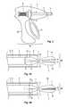
- FIG. 1is a perspective view of an endoscopic surgical forceps provided in accordance with the present disclosure
- FIG. 2is a side view of the proximal end of the forceps of FIG. 1 , with a portion of the housing removed to enable illustration of the internal features thereof;
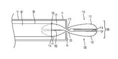
- FIG. 3Ais a longitudinal, cross-sectional view of the distal end of the forceps of FIG. 1 , wherein the jaw members are disposed in a spaced-apart position;
- FIG. 3Bis a longitudinal, cross-sectional view of the distal end of the forceps of FIG. 1 , wherein the jaw members are disposed in an approximated position;
- FIG. 4Ais a longitudinal, cross-sectional view of the distal end of another forceps similar to the forceps of FIG. 1 , wherein the jaw members are disposed in a spaced-apart position;
- FIG. 4Bis a longitudinal, cross-sectional view of the distal end of the forceps of FIG. 4A , wherein the jaw members are disposed in an approximated position;
- FIG. 5is a schematic illustration of a robotic surgical system configured for use in conjunction with aspects and features of the present disclosure.
- FIG. 1an embodiment of a surgical forceps provided in accordance with the present disclosure is shown generally identified by reference numeral 10 .
- surgical forceps 10is shown configured for use in connection with endoscopic surgical procedures, the present disclosure is equally applicable for use in more traditional open surgical procedures and with any suitable surgical instrument.
- Forceps 10generally includes a housing 20 , a handle assembly 30 , an activation switch 4 , and an end effector assembly 100 .
- Forceps 10further includes a shaft 12 having a distal end 14 configured to engage end effector assembly 100 and a proximal end 16 that engages housing 20 .
- Forceps 10also includes cable 2 that connects forceps 10 to an energy source (not shown), e.g., a generator or other suitable power source, although forceps 10 may alternatively be configured as a battery-powered device.
- Cable 2includes a wire (or wires) (not shown) extending therethrough that has sufficient length to extend through shaft 12 in order to provide energy to one or both tissue-treating surfaces 114 , 124 of jaw members 110 , 120 , respectively.
- Activation switch 4is coupled between tissue-treating surfaces 114 , 124 of jaw members 110 , 120 , respectively, and the source of energy for enabling the selective supply of energy to jaw members 110 , 120 for treating tissue graspe
- handle assembly 30includes a fixed handle 50 and a movable handle 40 .
- Fixed handle 50is integrally associated with housing 20 while movable handle 40 is pivotably coupled to housing 20 within housing 20 via a pivot 42 .
- Movable handle 40is also operably coupled to a drive assembly 60 operably associated with end effector assembly 100 that, together, mechanically cooperate to impart movement of one or both of jaw members 110 , 120 of end effector assembly 100 relative to each other between a spaced-apart position and an approximated position for grasping tissue therebetween.
- movable handle 40is coupled to a drive bar 62 via a drive mandrel 64 such that movement of movable handle 40 relative to fixed handle 50 effects longitudinal translation of drive bar 62 through shaft 12 and relative to end effector assembly 100 .
- At least the distal end 68 of drive bar 62defines a hollow configuration that is operably associated with one or both jaw members 110 , 120 such that, as detailed below, longitudinal translation of drive bar 62 relative to end effector assembly 100 moves one or both of jaw members 110 , 120 between the spaced-apart position and the approximated position.
- movable handle 40is initially spaced-apart from fixed handle 50 and, correspondingly, jaw members 110 , 120 are disposed in the spaced-apart position. Movable handle 40 is depressible from this initial position to a depressed position corresponding to the approximated position of jaw members 110 , 120 .
- a biasing member 66may be disposed about drive bar 62 and positioned to bias movable handle 40 apart from fixed handle 50 . However, other configurations are also contemplated.
- end effector assembly 100includes first and second jaw members 110 , 120 , each including a proximal portion 111 , 121 , a distal portion 112 , 122 , and an intermediate portion 113 , 123 extending between and interconnecting the respective proximal and distal portions 111 , 121 and 112 , 122 of jaw members 110 , 120 .
- Proximal portions 111 , 121 of jaw members 110 , 120respectively, oppose one another and distal portions 112 , 122 of jaw members 110 , 120 , respectively, oppose one another.
- jaw members 110 , 120overlap and cross-over one another at intermediate portions 113 , 123 , respectively, such that the orientation of the opposed proximal portions 111 , 121 is opposite that of the opposed distal portions 112 , 122 .
- Proximal portions 111 , 121 of jaw members 110 , 120are retained within distal end 14 of shaft 12 via a retention feature disposed at distal end 14 of shaft 12 .
- shaft 12defines an inwardly-extending, annular flange 15 at distal end 14 thereof that defines a reduced-diameter opening as compared to the inner diameter of shaft 12 .
- This reduced-diameter opening defined by annular flange 15inhibits the passage of proximal portions 111 , 121 of jaw members 110 , 120 , respectively, distally therethrough, thus retaining proximal portions 111 , 121 within distal end 14 of shaft 12 .
- Shaft 12may alternatively narrow at distal end 14 thereof to define a reduced-diameter opening, or may define any other suitable configuration for this purpose.
- Proximal portions 111 , 121also define cam surfaces 115 , 125 on the outwardly-facing surfaces thereof, the importance of which is detailed below.
- Hollow distal end 68 of drive bar 62is at least partially disposed about proximal portions 111 , 121 with cam surfaces 115 , 125 contacting the inner annular surface of drive bar 62 in operable association therewith, as also detailed below.
- a biasing member 102may interconnect proximal portions 111 , 121 on the inner-facing surfaces thereof so as to bias proximal portions 111 , 121 apart from one another.
- Distal portions 112 , 122 of jaw members 110 , 120each define a tissue-treating surface 114 , 124 , respectively, that is adapted to connect to the source of energy (not shown), e.g., via the wire (or wires) (not shown) extending from cable 2 ( FIG. 1 ) and through shaft 12 .
- Distal portions 112 , 122are movable relative to one another to grasp tissue between tissue-treating surfaces 114 , 124 . With tissue grasped between tissue-treating surface 114 , 124 , activation switch 4 ( FIG. 1 ) may be activated to supply energy to either or both tissue-treating surfaces 114 , 124 to treat tissue grasped therebetween.
- annular flange 15 at distal end 14 of shaft 12inhibits the passage of distal portions 112 , 122 of jaw members 110 , 120 , respectively, proximally therethrough.
- end effector assembly 100is operably retained at distal end 14 of shaft 12 .
- Intermediate portions 113 , 123 of jaw members 110 , 120define reduced dimensions as compared to proximal and distal portions 111 , 121 and 112 , 122 , respectively, thus enabling intermediate portions 113 , 123 to extend through the reduced-diameter opening defined by annular flange 15 of shaft 12 .
- jaw members 110 , 120overlap and cross-over one another at intermediate portions 113 , 123 thereof.
- movable handle 40is spaced-apart from fixed handle 50 under the bias of biasing member 66 and, thus, drive bar 62 is disposed in a more-proximal position, wherein hollow distal end 68 of drive bar 62 surrounds only the proximal-most sections of proximal portions 111 , 121 of jaw members 110 , 120 (see FIG. 3A ).
- proximal portions 111 , 1221are substantially uninhibited, thus permitting biasing member 102 to bias proximal portions 111 , 121 apart from one another, corresponding to the spaced-apart position of jaw members 110 , 120 (see FIG. 3A ).
- end effector assembly 100may be manipulated into position such that tissue to be grasped and/or treated is disposed between tissue-treating surfaces 114 , 124 of jaw members 110 , 120 , respectively.
- jaw members 110 , 120may be moved to the approximated position to grasp tissue between tissue-treating surfaces 114 , 124 .
- movable handle 40is depressed relative to fixed handle 50 to effect distal translation of drive bar 62 through shaft 12 and relative to end effector assembly 100 , e.g., to a more-distal position.
- This distal translation of drive bar 62urges hollow distal end 68 of drive bar 62 to further surround proximal portions 111 , 121 of jaw members 110 , 120 . More specifically, upon such distal translation of drive bar 62 , the inner annular surface of hollow distal end 68 of drive bar 62 is cammed over cam surfaces 115 , 125 of proximal portion 111 , 121 , thereby urging proximal portions 111 , 121 towards one another (see FIG. 3B ).
- activation switch 4may be activated to initiate the supply of energy to tissue-treating surfaces 114 , 124 for treating tissue grasped therebetween.
- jaw members 110 , 120may be returned to the spaced-apart position.
- movable handle 40is released or returned to its initial position, spaced-apart from fixed handle 50 , such that drive bar 62 is translated proximally through shaft 12 and relative to end effector assembly 100 .
- Proximal translation of drive bar 62 relative to end effector assembly 100retracts hollow distal end 68 of drive bar 62 from about proximal portions 111 , 121 of jaw members 110 , 120 , thus permitting biasing member 102 to bias proximal portions 111 , 121 apart from one another, thereby urging jaw members 110 , 120 back to the spaced-apart position.
- FIGS. 4A and 4Bthe distal end of another embodiment of a forceps 10 ′ provide in accordance with the present disclosure is shown generally including an outer shaft 12 ′, and end effector assembly 200 disposed at a distal end 14 ′ of outer shaft 12 ′, and a drive assembly 600 extending through outer shaft 12 ′ and operably associated with end effector assembly 200 .
- Forceps 10 ′may be configured similarly to and/or include any of the features of forceps 10 ( FIGS. 1 and 2 ), e.g., forceps 10 ′ may include a housing supported at the proximal end of outer shaft 12 ′ similar to housing 20 ( FIG. 1 ) and a handle assembly for selectively actuating drive assembly 600 similar to handle assembly 30 ( FIGS. 1 and 2 ), except as specifically contradicted below.
- End effector assembly 200includes first and second jaw members 210 , 220 each including a proximal portion 211 , 221 and a distal portion 212 , 222 .
- Jaw members 210 , 220are each monolithically formed from a flexible material, e.g., an insulative, biocompatible polymer, although other configurations are also contemplated.
- Jaw members 210 , 220may be formed from a resilient material so as to bias jaw members 210 , 220 towards the spaced-apart position, although other configurations and/or biasing structure are also contemplated.
- Proximal portions 211 , 221 of jaw members 210 , 220each define arcuate configurations and are oriented oppositely of one another such that the arcuate proximal portions 211 , 221 intersect each other at two intersection areas 202 , 204 .
- One of the proximal portions 211 , 221defines a recess 203 a adjacent the first intersection area 202
- the other proximal portion 211 , 221defines a complementary protrusion 203 b adjacent the first intersection area 202 .
- one of the proximal portions 211 , 221defines a recess 205 a adjacent the second intersection area 204
- the other proximal portion 211 , 221defines a complementary protrusion 205 b adjacent the second intersection area 204
- Recess 203 a , 205 aare configured to receive complementary protrusions 203 b , 205 b , respectively, so as to engage proximal portions 211 , 221 of jaw members 210 , 220 with one another in an inter-fit manner such that proximal portions 211 , 221 are retained in substantially fixed position and orientation relative to one another.
- Distal portions 212 , 222 of jaw members 210 , 220respectively, defining opposed surfaces having tissue-treating plates 214 , 224 disposed thereon.
- Tissue-treating plates 214 , 224define tissue-treating surfaces 215 , 225 configured to grasp tissue therebetween in the approximated position of jaw members 210 , 220 .
- Either or both of tissue-treating plates 214 , 224are adapted to connect to the source of energy (not shown) for treating tissue grasped between tissue-treating surfaces 215 , 225 .
- Distal portions 212 , 222further define cam surfaces 216 , 226 on the outwardly-facing surfaces thereof, the importance of which is detailed below.
- jaw members 210 , 220Due to the flexible configuration of jaw members 210 , 220 , despite proximal portions 211 , 221 of jaw members 210 , 220 being retained in substantially fixed position and orientation relative to one another, flexion of one or both of jaw members 210 , 220 intermediate proximal and distal portions 211 , 221 and 212 , 222 , respectively, permits distal portions 212 , 222 to move relative to one another between the spaced-apart position of jaw members 210 , 220 and the approximated position of jaw members 210 , 220 for grasping tissue therebetween.
- the term “substantially fixed position and orientation”is meant to allow for some degree of flexion and/or movement of proximal portions 211 , 221 that is not the primary cause of jaw members 210 , 220 moving between the spaced-apart and approximated positions. Rather, it is the flexion of jaw members 210 , 220 that allows for such movement between the spaced-apart and approximated positions. As can be appreciated, this configuration obviates the need for a pivot structure interconnecting jaw members 210 , 220 .
- Drive assembly 600includes a fixed inner drive bar 610 that is disposed within and fixed relative to outer shaft 12 ′, and a movable outer drive bar 620 that is slidably disposed between fixed inner drive bar 610 and outer shaft 12 ′.
- Drive assembly 600may further include components and/or features similar to those detailed above with respect to drive assembly 60 ( FIG. 2 ) for translating movable outer drive bar 620 about fixed inner drive bar 610 and relative to outer shaft 12 ′ and end effector assembly 200 , e.g., upon actuation of a movable handle or other suitable actuator.
- At least distal end 612 of fixed inner drive bar 610is hollow and configured to receive the inter-fit proximal portions 211 , 221 of jaw members 210 , 220 , respectively, of end effector assembly 200 .
- one or more retention structurese.g., rings 614 (although other suitable retention structures are also contemplated). Rings 614 are positioned to retain the inter-fit proximal portions 211 , 221 of jaw members 210 , 220 of end effector assembly 200 within hollow distal end 612 of fixed inner drive bar 610 upon insertion therein.
- proximal portions 211 , 221 of jaw members 210 , 220may first be inter-fit with one another and then inserted into hollow distal end 612 of jaw member 210 , 220 under sufficient urging so as to pass at least partially through rings 614 and into position with rings 614 disposed adjacent intersection areas 202 , 204 , thereby retaining proximal portions 211 , 221 of jaw members 210 , 220 in substantially fixed position and orientation relative to one another and fixed inner drive bar 610 .
- Movable outer drive bar 620is slidably disposed between fixed inner drive bar 610 and outer shaft 12 ′ and is coupled to suitable components of drive assembly 600 so as to be selectively translatable about fixed inner drive bar 610 and relative to outer shaft 12 ′ and end effector assembly 200 , e.g., upon actuation of a movable handle or other suitable actuator.
- the distal end of movable outer drive bar 620may further define a beveled annular edge 622 to facilitate camming about cam surfaces 216 , 226 of distal portions 212 , 222 of jaw members 210 , 220 , respectively, as detailed below.
- movable outer drive bar 620is disposed in a more-proximal position, wherein the beveled annular edge 622 defined at the distal end of movable outer drive bar 620 is spaced proximally from distal portions 212 , 222 of jaw members 210 , 220 , respectively.
- distal portions 212 , 222 of jaw members 210 , 220are substantially uninhibited such that jaw members 210 , 220 are resiliently (or otherwise) biased towards the spaced-apart position ( FIG. 4A ).
- end effector assembly 200may be manipulated into position as desired, similarly as detailed above.
- jaw members 210 , 220may be moved to the approximated position to grasp tissue between tissue-treating surfaces 215 , 225 .
- movable outer drive bar 620is translated distally about fixed inner drive bar 610 and relative to outer shaft 12 ′ and end effector assembly 200 , e.g., upon actuation of a movable handle or other suitable actuator.
- This distal translation of movable outer drive bar 620urges beveled annular edge 622 of movable outer drive bar 620 to cam about cam surfaces 216 , 226 of distal portions 212 , 222 of jaw members 210 , 220 , respectively, thereby urging jaw members 210 , 220 to flex such that distal portions 212 , 222 are moved towards one another to the approximated position ( FIG. 4B ) to grasp tissue between tissue-treating surfaces 215 , 225 .
- tissue grasped between tissue-treating surfaces 215 , 225energy may be supplied to tissue-treating plate 214 and/or tissue-treating plate 224 for treating tissue grasped between tissue-treating surfaces 215 , 225 .
- tissue-treating plate 214 and/or tissue-treating plate 224may be supplied to tissue-treating plate 214 and/or tissue-treating plate 224 for treating tissue grasped between tissue-treating surfaces 215 , 225 .
- jaw members 210 , 220may be returned to the spaced-apart position.
- movable outer drive bar 620is returned proximally.
- Proximal translation of movable outer drive bar 620 relative to end effector assembly 200retracts movable outer drive bar 620 from about distal portions 212 , 222 of jaw members 210 , 220 , thus permitting jaw members 210 , 220 to resiliently return to the spaced-apart position ( FIG. 4A ).
- the various embodiments disclosed hereinmay also be configured to work with robotic surgical systems and what is commonly referred to as “Telesurgery.”
- Such systemsemploy various robotic elements to assist the surgeon and allow remote operation (or partial remote operation) of surgical instrumentation.
- Various robotic arms, gears, cams, pulleys, electric and mechanical motors, etc.may be employed for this purpose and may be designed with a robotic surgical system to assist the surgeon during the course of an operation or treatment.
- Such robotic systemsmay include remotely steerable systems, automatically flexible surgical systems, remotely flexible surgical systems, remotely articulating surgical systems, wireless surgical systems, modular or selectively configurable remotely operated surgical systems, etc.
- the robotic surgical systemsmay be employed with one or more consoles that are next to the operating theater or located in a remote location.
- one team of surgeons or nursesmay prep the patient for surgery and configure the robotic surgical system with one or more of the instruments disclosed herein while another surgeon (or group of surgeons) remotely control the instruments via the robotic surgical system.
- a highly skilled surgeonmay perform multiple operations in multiple locations without leaving his/her remote console which can be both economically advantageous and a benefit to the patient or a series of patients.
- the robotic arms of the surgical systemare typically coupled to a pair of master handles by a controller.
- the handlescan be moved by the surgeon to produce a corresponding movement of the working ends of any type of surgical instrument (e.g., end effectors, graspers, knifes, scissors, etc.) which may complement the use of one or more of the embodiments described herein.
- the movement of the master handlesmay be scaled so that the working ends have a corresponding movement that is different, smaller or larger, than the movement performed by the operating hands of the surgeon.
- the scale factor or gearing ratiomay be adjustable so that the operator can control the resolution of the working ends of the surgical instrument(s).
- the master handlesmay include various sensors to provide feedback to the surgeon relating to various tissue parameters or conditions, e.g., tissue resistance due to manipulation, cutting or otherwise treating, pressure by the instrument onto the tissue, tissue temperature, tissue impedance, etc. As can be appreciated, such sensors provide the surgeon with enhanced tactile feedback simulating actual operating conditions.
- the master handlesmay also include a variety of different actuators for delicate tissue manipulation or treatment further enhancing the surgeon's ability to mimic actual operating conditions.
- a medical work stationis shown generally as work station 1000 and generally may include a plurality of robot arms 1002 , 1003 ; a control device 1004 ; and an operating console 1005 coupled with control device 1004 .
- Operating console 1005may include a display device 1006 , which may be set up in particular to display three-dimensional images; and manual input devices 1007 , 1008 , by means of which a person (not shown), for example a surgeon, may be able to telemanipulate robot arms 1002 , 1003 in a first operating mode.
- Each of the robot arms 1002 , 1003may include a plurality of members, which are connected through joints, and an attaching device 1009 , 1011 , to which may be attached, for example, a surgical tool “ST” supporting an end effector 1100 , in accordance with any one of several embodiments disclosed herein, as will be described in greater detail below.
- Robot arms 1002 , 1003may be driven by electric drives (not shown) that are connected to control device 1004 .
- Control device 1004e.g., a computer
- Control device 1004may be set up to activate the drives, in particular by means of a computer program, in such a way that robot arms 1002 , 1003 , their attaching devices 1009 , 1011 and thus the surgical tool (including end effector 1100 ) execute a desired movement according to a movement defined by means of manual input devices 1007 , 1008 .
- Control device 1004may also be set up in such a way that it regulates the movement of robot arms 1002 , 1003 and/or of the drives.
- Medical work station 1000may be configured for use on a patient 1013 lying on a patient table 1012 to be treated in a minimally invasive manner by means of end effector 1100 .
- Medical work station 1000may also include more than two robot arms 1002 , 1003 , the additional robot arms likewise being connected to control device 1004 and being telemanipulatable by means of operating console 1005 .
- a medical instrument or surgical tool(including an end effector 1100 ) may also be attached to the additional robot arm.
- Medical work station 1000may include a database 1014 , in particular coupled to with control device 1004 , in which are stored, for example, pre-operative data from patient/living being 1013 and/or anatomical atlases.
Landscapes
- Health & Medical Sciences (AREA)
- Life Sciences & Earth Sciences (AREA)
- Surgery (AREA)
- Engineering & Computer Science (AREA)
- Medical Informatics (AREA)
- Veterinary Medicine (AREA)
- Biomedical Technology (AREA)
- Heart & Thoracic Surgery (AREA)
- Nuclear Medicine, Radiotherapy & Molecular Imaging (AREA)
- Molecular Biology (AREA)
- Animal Behavior & Ethology (AREA)
- General Health & Medical Sciences (AREA)
- Public Health (AREA)
- Physics & Mathematics (AREA)
- Plasma & Fusion (AREA)
- Otolaryngology (AREA)
- Ophthalmology & Optometry (AREA)
- Surgical Instruments (AREA)
Abstract
Description
Claims (8)
Priority Applications (1)
| Application Number | Priority Date | Filing Date | Title |
|---|---|---|---|
| US14/722,514US10441340B2 (en) | 2015-05-27 | 2015-05-27 | Surgical forceps |
Applications Claiming Priority (1)
| Application Number | Priority Date | Filing Date | Title |
|---|---|---|---|
| US14/722,514US10441340B2 (en) | 2015-05-27 | 2015-05-27 | Surgical forceps |
Publications (2)
| Publication Number | Publication Date |
|---|---|
| US20160345992A1 US20160345992A1 (en) | 2016-12-01 |
| US10441340B2true US10441340B2 (en) | 2019-10-15 |
Family
ID=57396984
Family Applications (1)
| Application Number | Title | Priority Date | Filing Date |
|---|---|---|---|
| US14/722,514Expired - Fee RelatedUS10441340B2 (en) | 2015-05-27 | 2015-05-27 | Surgical forceps |
Country Status (1)
| Country | Link |
|---|---|
| US (1) | US10441340B2 (en) |
Citations (167)
| Publication number | Priority date | Publication date | Assignee | Title |
|---|---|---|---|---|
| SU401367A1 (en) | 1971-10-05 | 1973-10-12 | Тернопольский государственный медицинский институт | BIAKTIVNYE ELECTRO SURGICAL INSTRUMENT |
| DE2415263A1 (en) | 1974-03-29 | 1975-10-02 | Aesculap Werke Ag | Surgical H.F. coagulation probe has electrode tongs - with exposed ends of insulated conductors forming tong-jaws |
| DE2514501A1 (en) | 1975-04-03 | 1976-10-21 | Karl Storz | Bipolar coagulation instrument for endoscopes - has two high frequency electrodes looped over central insulating piece |
| DE2627679A1 (en) | 1975-06-26 | 1977-01-13 | Marcel Lamidey | HEMATISTIC HIGH FREQUENCY EXTRACTOR FORCEPS |
| USD249549S (en) | 1976-10-22 | 1978-09-19 | Aspen Laboratories, Inc. | Electrosurgical handle |
| USD263020S (en) | 1980-01-22 | 1982-02-16 | Rau Iii David M | Retractable knife |
| JPS61501068A (en) | 1984-01-30 | 1986-05-29 | ハルコフスキイ ナウチノ−イススレドワテルスキイ インスチチユ−ト オブスチエイ イ ネオトロジノイ ヒルルギイ | bipolar electrosurgical instrument |
| DE3423356C2 (en) | 1984-06-25 | 1986-06-26 | Berchtold Medizin-Elektronik GmbH & Co, 7200 Tuttlingen | Electrosurgical high frequency cutting instrument |
| DE3612646A1 (en) | 1985-04-16 | 1987-04-30 | Ellman International | Electrosurgical handle piece for blades, needles and forceps |
| DE3627221A1 (en) | 1986-01-15 | 1988-02-18 | Siemens Ag | HF SURGERY DEVICE WITH POWER CONTROL FROM THE SURGICAL HANDLE |
| DE8712328U1 (en) | 1987-09-11 | 1988-02-18 | Jakoubek, Franz, 7201 Emmingen-Liptingen | Endoscopy forceps |
| USD295894S (en) | 1985-09-26 | 1988-05-24 | Acme United Corporation | Disposable surgical scissors |
| USD295893S (en) | 1985-09-25 | 1988-05-24 | Acme United Corporation | Disposable surgical clamp |
| USD298353S (en) | 1986-05-06 | 1988-11-01 | Vitalmetrics, Inc. | Handle for surgical instrument |
| USD299413S (en) | 1985-07-17 | 1989-01-17 | The Stanley Works | Folding pocket saw handle |
| JPH055106A (en) | 1990-07-31 | 1993-01-14 | Matsushita Electric Works Ltd | Production of alloy sintered body |
| JPH0540112A (en) | 1991-02-08 | 1993-02-19 | Tokico Ltd | Sample liquid component analyzer |
| USD343453S (en) | 1993-05-05 | 1994-01-18 | Laparomed Corporation | Handle for laparoscopic surgical instrument |
| JPH0630945A (en) | 1992-05-19 | 1994-02-08 | Olympus Optical Co Ltd | Suturing apparatus |
| JPH06502328A (en) | 1990-10-17 | 1994-03-17 | ボストン サイエンティフィック コーポレイション | Surgical instruments and methods |
| JPH06121797A (en) | 1992-02-27 | 1994-05-06 | United States Surgical Corp | Equipment and method for performing intracutaneous stapling of body tissue |
| USD348930S (en) | 1991-10-11 | 1994-07-19 | Ethicon, Inc. | Endoscopic stapler |
| USD349341S (en) | 1992-10-28 | 1994-08-02 | Microsurge, Inc. | Endoscopic grasper |
| JPH06285078A (en) | 1993-04-05 | 1994-10-11 | Olympus Optical Co Ltd | Forceps |
| JPH06343644A (en) | 1993-05-04 | 1994-12-20 | Gyrus Medical Ltd | Surgical peritoneoscope equipment |
| JPH06511401A (en) | 1991-06-07 | 1994-12-22 | バイタル メディカル プロダクツ コーポレイション | Bipolar electrosurgical endoscopic instrument and its method of use |
| USD354564S (en) | 1993-06-25 | 1995-01-17 | Richard-Allan Medical Industries, Inc. | Surgical clip applier |
| DE4303882C2 (en) | 1993-02-10 | 1995-02-09 | Kernforschungsz Karlsruhe | Combination instrument for separation and coagulation for minimally invasive surgery |
| USD358887S (en) | 1993-12-02 | 1995-05-30 | Cobot Medical Corporation | Combined cutting and coagulating forceps |
| DE4403252A1 (en) | 1994-02-03 | 1995-08-10 | Michael Hauser | Instrument shaft for min. invasive surgery |
| JPH07265328A (en) | 1993-11-01 | 1995-10-17 | Gyrus Medical Ltd | Electrode assembly for electric surgery device and electric surgery device using it |
| JPH0856955A (en) | 1994-06-29 | 1996-03-05 | Gyrus Medical Ltd | Electric surgical apparatus |
| DE19515914C1 (en) | 1995-05-02 | 1996-07-25 | Aesculap Ag | Tong or scissor-shaped surgical instrument |
| DE19506363A1 (en) | 1995-02-24 | 1996-08-29 | Frost Lore Geb Haupt | Non-invasive thermometry in organs under hyperthermia and coagulation conditions |
| JPH08252263A (en) | 1994-12-21 | 1996-10-01 | Gyrus Medical Ltd | Electronic surgical incision instrument and electronic surgical incision device using the same |
| JPH08289895A (en) | 1995-04-21 | 1996-11-05 | Olympus Optical Co Ltd | Suture device |
| DE29616210U1 (en) | 1996-09-18 | 1996-11-14 | Olympus Winter & Ibe Gmbh, 22045 Hamburg | Handle for surgical instruments |
| JPH08317934A (en) | 1995-04-12 | 1996-12-03 | Ethicon Endo Surgery Inc | Hemostatic device for electric surgery with adaptable electrode |
| JPH08317936A (en) | 1995-01-18 | 1996-12-03 | Ethicon Endo Surgery Inc | Hemostatic device for electric surgery provided with recessed type and/or crossed type electrode |
| JPH09538A (en) | 1995-06-21 | 1997-01-07 | Fuji Photo Optical Co Ltd | High-frequency medical treatment instrument |
| JPH0910223A (en) | 1995-06-23 | 1997-01-14 | Gyrus Medical Ltd | Generator and system for electric operation |
| DE19608716C1 (en) | 1996-03-06 | 1997-04-17 | Aesculap Ag | Bipolar surgical holding instrument |
| JPH09122138A (en) | 1995-10-20 | 1997-05-13 | Ethicon Endo Surgery Inc | Apparatus for operation |
| USD384413S (en) | 1994-10-07 | 1997-09-30 | United States Surgical Corporation | Endoscopic suturing instrument |
| JPH10195A (en) | 1996-03-05 | 1998-01-06 | Ethicon Endo Surgery Inc | Surgical suturing machine with fixing mechanism |
| US5709680A (en) | 1993-07-22 | 1998-01-20 | Ethicon Endo-Surgery, Inc. | Electrosurgical hemostatic device |
| JPH1024051A (en) | 1995-09-20 | 1998-01-27 | Olympus Optical Co Ltd | Coagulation forceps with separating function |
| DE19751106A1 (en) | 1996-11-27 | 1998-05-28 | Eastman Kodak Co | Laser printer with array of laser diodes |
| JPH10155798A (en) | 1996-12-04 | 1998-06-16 | Asahi Optical Co Ltd | Hot biopsy forceps for endoscopes |
| USH1745H (en) | 1995-09-29 | 1998-08-04 | Paraschac; Joseph F. | Electrosurgical clamping device with insulation limited bipolar electrode |
| USD402028S (en) | 1997-10-10 | 1998-12-01 | Invasatec, Inc. | Hand controller for medical system |
| JPH1147149A (en) | 1997-08-04 | 1999-02-23 | Olympus Optical Co Ltd | Endoscopic surgery appliance |
| JPH1147150A (en) | 1997-08-06 | 1999-02-23 | Olympus Optical Co Ltd | Endoscopic surgery appliance |
| JPH1170124A (en) | 1997-05-14 | 1999-03-16 | Ethicon Endo Surgery Inc | Improved electrosurgical hemostatic apparatus having anvil |
| USD408018S (en) | 1996-03-12 | 1999-04-13 | Mcnaughton Patrick J | Switch guard |
| DE19751108A1 (en) | 1997-11-18 | 1999-05-20 | Beger Frank Michael Dipl Desig | Electrosurgical operation tool, especially for diathermy |
| JPH11169381A (en) | 1997-12-15 | 1999-06-29 | Olympus Optical Co Ltd | High frequency treating device |
| US5922002A (en) | 1989-12-05 | 1999-07-13 | Yoon; Inbae | Surgical instrument with jaws and movable internal biopsy device and method for use thereof |
| JPH11192238A (en) | 1997-10-10 | 1999-07-21 | Ethicon Endo Surgery Inc | Ultrasonic forceps coagulation device improved of pivot-attaching of forceps arm |
| JPH11244298A (en) | 1997-12-19 | 1999-09-14 | Gyrus Medical Ltd | Electric surgical instrument |
| USD416089S (en) | 1996-04-08 | 1999-11-02 | Richard-Allan Medical Industries, Inc. | Endoscopic linear stapling and dividing surgical instrument |
| JP2000102545A (en) | 1997-06-18 | 2000-04-11 | Eggers & Associates Inc | Electric tweezers for surgery |
| USD424694S (en) | 1998-10-23 | 2000-05-09 | Sherwood Services Ag | Forceps |
| USD425201S (en) | 1998-10-23 | 2000-05-16 | Sherwood Services Ag | Disposable electrode assembly |
| JP2000135222A (en) | 1998-08-27 | 2000-05-16 | Olympus Optical Co Ltd | High frequency treatment device |
| WO2000036986A1 (en) | 1998-12-18 | 2000-06-29 | Karl Storz Gmbh & Co. Kg | Bipolar medical instrument |
| USH1904H (en) | 1997-05-14 | 2000-10-03 | Ethicon Endo-Surgery, Inc. | Electrosurgical hemostatic method and device |
| WO2000059392A1 (en) | 1999-04-01 | 2000-10-12 | Erbe Elektromedizin | Surgical instrument |
| JP2000342599A (en) | 1999-05-21 | 2000-12-12 | Gyrus Medical Ltd | Generator for electrosurgical operation, electrosurgical operation system, method for operating this system and method for performing amputation and resection of tissue by electrosurgical operation |
| JP2000350732A (en) | 1999-05-21 | 2000-12-19 | Gyrus Medical Ltd | Electrosurgical system, generator for electrosurgery, and method for cutting or excising tissue by electrosurgery |
| JP2001003400A (en) | 1999-06-21 | 2001-01-09 | Sumitomo Constr Mach Co Ltd | Monitor device for hydraulic shovel |
| JP2001008944A (en) | 1999-05-28 | 2001-01-16 | Gyrus Medical Ltd | Electric surgical signal generator and electric surgical system |
| JP2001029355A (en) | 1999-07-21 | 2001-02-06 | Olympus Optical Co Ltd | Electric cautery device |
| JP2001029356A (en) | 1999-06-11 | 2001-02-06 | Gyrus Medical Ltd | Electric and surgical signal generator |
| WO2001015614A1 (en) | 1999-08-27 | 2001-03-08 | Karl Storz Gmbh & Co. Kg | Bipolar medical instrument |
| JP2001128990A (en) | 1999-05-28 | 2001-05-15 | Gyrus Medical Ltd | Electro surgical instrument and electrosurgical tool converter |
| DE19946527C1 (en) | 1999-09-28 | 2001-07-12 | Storz Karl Gmbh & Co Kg | Bipolar, e.g. laparoscopic surgery instrument, cuts electrically, cauterizes and grips using simple design with high frequency current-concentrating projections |
| JP2001190564A (en) | 2000-01-12 | 2001-07-17 | Olympus Optical Co Ltd | Medical treatment instrument |
| WO2001054604A1 (en) | 2000-01-25 | 2001-08-02 | Aesculap Ag & Co. Kg | Bipolar gripping device |
| USD449886S1 (en) | 1998-10-23 | 2001-10-30 | Sherwood Services Ag | Forceps with disposable electrode |
| EP1159926A2 (en) | 2000-06-03 | 2001-12-05 | Aesculap Ag | Scissor- or forceps-like surgical instrument |
| USD453923S1 (en) | 2000-11-16 | 2002-02-26 | Carling Technologies, Inc. | Electrical rocker switch guard |
| USD454951S1 (en) | 2001-02-27 | 2002-03-26 | Visionary Biomedical, Inc. | Steerable catheter |
| DE20121161U1 (en) | 2001-01-31 | 2002-04-04 | Olympus Winter & Ibe Gmbh, 22045 Hamburg | Endoscopic instrument |
| JP2002136525A (en) | 2000-10-30 | 2002-05-14 | Olympus Optical Co Ltd | Surgical instrument |
| USD457958S1 (en) | 2001-04-06 | 2002-05-28 | Sherwood Services Ag | Vessel sealer and divider |
| USD457959S1 (en) | 2001-04-06 | 2002-05-28 | Sherwood Services Ag | Vessel sealer |
| WO2002045589A2 (en) | 2000-12-08 | 2002-06-13 | Gfd Gesellschaft Für Diamantprodukte Mbh | Instrument, which is provided for surgical applications and which comprises contact areas made of doped diamond, and method for cleaning the instrument |
| JP2002528166A (en) | 1998-10-23 | 2002-09-03 | シャーウッド サーヴィシス アクチェンゲゼルシャフト | Externally-opened vascular sealing forceps with disposable electrodes |
| DE10045375C2 (en) | 2000-09-14 | 2002-10-24 | Aesculap Ag & Co Kg | Medical instrument |
| USD465281S1 (en) | 1999-09-21 | 2002-11-05 | Karl Storz Gmbh & Co. Kg | Endoscopic medical instrument |
| USD466209S1 (en) | 2001-02-27 | 2002-11-26 | Visionary Biomedical, Inc. | Steerable catheter |
| EP1281878A1 (en) | 2001-08-02 | 2003-02-05 | Peugeot Citroen Automobiles | Pivot pin between two elements |
| JP2003116871A (en) | 2001-10-16 | 2003-04-22 | Olympus Optical Co Ltd | Surgical tool |
| US6554829B2 (en) | 2001-01-24 | 2003-04-29 | Ethicon, Inc. | Electrosurgical instrument with minimally invasive jaws |
| JP2003175052A (en) | 2002-11-01 | 2003-06-24 | Olympus Optical Co Ltd | Coagulation treatment tool |
| JP2003245285A (en) | 2002-01-23 | 2003-09-02 | Ethicon Endo Surgery Inc | Feedback light apparatus and method for use with electrosurgical instrument |
| JP2004517668A (en) | 2000-10-20 | 2004-06-17 | オーナックス・メディカル・インコーポレーテッド | Surgical suturing instrument and method of use |
| USD493888S1 (en) | 2003-02-04 | 2004-08-03 | Sherwood Services Ag | Electrosurgical pencil with pistol grip |
| JP2004528869A (en) | 2001-01-26 | 2004-09-24 | エシコン・エンド−サージェリィ・インコーポレイテッド | Electrosurgical instruments for coagulation and cutting |
| USD496997S1 (en) | 2003-05-15 | 2004-10-05 | Sherwood Services Ag | Vessel sealer and divider |
| USD499181S1 (en) | 2003-05-15 | 2004-11-30 | Sherwood Services Ag | Handle for a vessel sealer and divider |
| USD502994S1 (en) | 2003-05-21 | 2005-03-15 | Blake, Iii Joseph W | Repeating multi-clip applier |
| JP2005152663A (en) | 2003-11-20 | 2005-06-16 | Sherwood Services Ag | Electrically conductive/insulative over-shoe for tissue fusion |
| USD509297S1 (en) | 2003-10-17 | 2005-09-06 | Tyco Healthcare Group, Lp | Surgical instrument |
| JP2005253789A (en) | 2004-03-12 | 2005-09-22 | Olympus Corp | Treatment instrument for operation |
| JP2005312807A (en) | 2004-04-30 | 2005-11-10 | Olympus Corp | Energy therapy device |
| WO2005110264A2 (en) | 2004-05-14 | 2005-11-24 | Erbe Elektromedizin Gmbh | Electrosurgical instrument |
| JP2006015078A (en) | 2004-07-05 | 2006-01-19 | Olympus Corp | Medical apparatus |
| JP2006501939A (en) | 2002-10-04 | 2006-01-19 | シャーウッド・サービシーズ・アクチェンゲゼルシャフト | Electrode assembly for sealing and cutting tissue and method for performing sealing and cutting tissue |
| WO2006021269A1 (en) | 2004-08-24 | 2006-03-02 | Erbe Elektromedizin Gmbh | Surgical instrument |
| JP2006095316A (en) | 2004-09-29 | 2006-04-13 | Sherwood Services Ag | Vessel sealer and divider having elongated knife stroke and safety for cutting mechanism |
| USD525361S1 (en) | 2004-10-06 | 2006-07-18 | Sherwood Services Ag | Hemostat style elongated dissecting and dividing instrument |
| USD531311S1 (en) | 2004-10-06 | 2006-10-31 | Sherwood Services Ag | Pistol grip style elongated dissecting and dividing instrument |
| USD533274S1 (en) | 2004-10-12 | 2006-12-05 | Allegiance Corporation | Handle for surgical suction-irrigation device |
| USD533942S1 (en) | 2004-06-30 | 2006-12-19 | Sherwood Services Ag | Open vessel sealer with mechanical cutter |
| USD535027S1 (en) | 2004-10-06 | 2007-01-09 | Sherwood Services Ag | Low profile vessel sealing and cutting mechanism |
| USD538932S1 (en) | 2005-06-30 | 2007-03-20 | Medical Action Industries Inc. | Surgical needle holder |
| USD541418S1 (en) | 2004-10-06 | 2007-04-24 | Sherwood Services Ag | Lung sealing device |
| USD541938S1 (en) | 2004-04-09 | 2007-05-01 | Sherwood Services Ag | Open vessel sealer with mechanical cutter |
| USD541611S1 (en) | 2006-01-26 | 2007-05-01 | Robert Bosch Gmbh | Cordless screwdriver |
| USD545432S1 (en) | 2003-08-08 | 2007-06-26 | Olympus Corporation | Distal portion of hemostatic forceps for endoscope |
| USD547154S1 (en) | 2006-09-08 | 2007-07-24 | Winsource Industries Limited | Rotary driving tool |
| DE202007009165U1 (en) | 2007-06-29 | 2007-08-30 | Kls Martin Gmbh + Co. Kg | Surgical instrument e.g. tube shaft, for use in e.g. high frequency coagulation instrument, has separator inserted through opening such that largest extension of opening transverse to moving direction corresponds to dimension of separator |
| DE202007009318U1 (en) | 2007-06-26 | 2007-08-30 | Aesculap Ag & Co. Kg | Surgical instrument |
| DE202007009317U1 (en) | 2007-06-26 | 2007-08-30 | Aesculap Ag & Co. Kg | Surgical instrument |
| DE10031773B4 (en) | 2000-05-04 | 2007-11-29 | Erbe Elektromedizin Gmbh | Surgical gripping instrument, in particular tweezers or forceps |
| DE202007016233U1 (en) | 2007-11-20 | 2008-01-31 | Aesculap Ag & Co. Kg | Surgical forceps |
| JP2008054926A (en) | 2006-08-31 | 2008-03-13 | Shiga Univ Of Medical Science | Microwave surgical device |
| USD564662S1 (en) | 2004-10-13 | 2008-03-18 | Sherwood Services Ag | Hourglass-shaped knife for electrosurgical forceps |
| WO2008040483A1 (en) | 2006-10-05 | 2008-04-10 | Erbe Elektromedizin Gmbh | Tubular shaft instrument |
| USD567943S1 (en) | 2004-10-08 | 2008-04-29 | Sherwood Services Ag | Over-ratchet safety for a vessel sealing instrument |
| USD575395S1 (en) | 2007-02-15 | 2008-08-19 | Tyco Healthcare Group Lp | Hemostat style elongated dissecting and dividing instrument |
| USD575401S1 (en) | 2007-06-12 | 2008-08-19 | Tyco Healthcare Group Lp | Vessel sealer |
| USD582038S1 (en) | 2004-10-13 | 2008-12-02 | Medtronic, Inc. | Transurethral needle ablation device |
| DE19738457B4 (en) | 1997-09-03 | 2009-01-02 | Celon Ag Medical Instruments | Method and device for in vivo deep coagulation of biological tissue volumes while sparing the tissue surface with high frequency alternating current |
| DE102008018406B3 (en) | 2008-04-10 | 2009-07-23 | Bowa-Electronic Gmbh & Co. Kg | Electrosurgical device |
| CN201299462Y (en) | 2008-10-28 | 2009-09-02 | 宋洪海 | Multi-layer metal composite pot |
| US7628792B2 (en) | 2004-10-08 | 2009-12-08 | Covidien Ag | Bilateral foot jaws |
| USD617902S1 (en) | 2009-05-13 | 2010-06-15 | Tyco Healthcare Group Lp | End effector tip with undercut top jaw |
| USD617903S1 (en) | 2009-05-13 | 2010-06-15 | Tyco Healthcare Group Lp | End effector pointed tip |
| USD617901S1 (en) | 2009-05-13 | 2010-06-15 | Tyco Healthcare Group Lp | End effector chamfered tip |
| USD617900S1 (en) | 2009-05-13 | 2010-06-15 | Tyco Healthcare Group Lp | End effector tip with undercut bottom jaw |
| USD618798S1 (en) | 2009-05-13 | 2010-06-29 | Tyco Healthcare Group Lp | Vessel sealing jaw seal plate |
| USD621503S1 (en) | 2009-04-28 | 2010-08-10 | Tyco Healthcare Group Ip | Pistol grip laparoscopic sealing and dissection device |
| USD627462S1 (en) | 2009-09-09 | 2010-11-16 | Tyco Healthcare Group Lp | Knife channel of a jaw device |
| US7837631B2 (en) | 2003-03-14 | 2010-11-23 | Boston Scientific Scimed Inc. | Biopsy forceps with removable jaw segments |
| USD628290S1 (en) | 2009-11-30 | 2010-11-30 | Tyco Healthcare Group Lp | Surgical instrument handle |
| USD628289S1 (en) | 2009-11-30 | 2010-11-30 | Tyco Healthcare Group Lp | Surgical instrument handle |
| USD630324S1 (en) | 2009-08-05 | 2011-01-04 | Tyco Healthcare Group Lp | Dissecting surgical jaw |
| WO2011018154A1 (en) | 2009-08-14 | 2011-02-17 | Erbe Elektromedizin Gmbh | Electrosurgical instrument |
| US7935052B2 (en) | 2004-09-09 | 2011-05-03 | Covidien Ag | Forceps with spring loaded end effector assembly |
| JP2011125195A (en) | 2009-12-14 | 2011-06-23 | Chugoku Electric Power Co Inc:The | Supporter for indirect hot-line work |
| USD649249S1 (en) | 2007-02-15 | 2011-11-22 | Tyco Healthcare Group Lp | End effectors of an elongated dissecting and dividing instrument |
| USD649643S1 (en) | 2009-05-13 | 2011-11-29 | Tyco Healthcare Group Lp | End effector with a rounded tip |
| US20110295314A1 (en) | 2010-06-01 | 2011-12-01 | Ralf Staud | Medical gripping tool |
| US20120101484A1 (en)* | 2009-07-01 | 2012-04-26 | Olympus Winter & Ibe Gmbh | Surgical jaw instrument having a slide system |
| US20120130367A1 (en)* | 2010-11-19 | 2012-05-24 | Tyco Healthcare Group Lp | Apparatus for Performing an Electrosurgical Procedure |
| USD661394S1 (en) | 2011-02-24 | 2012-06-05 | Tyco Healthcare Group Lp | Device jaw |
| USD670808S1 (en) | 2010-10-01 | 2012-11-13 | Tyco Healthcare Group Lp | Open vessel sealing forceps |
| US8382792B2 (en) | 2008-02-14 | 2013-02-26 | Covidien Lp | End effector assembly for electrosurgical device |
| US20130085516A1 (en)* | 2011-10-03 | 2013-04-04 | Tyco Healthcare Group Lp | Surgical Forceps |
| USD680220S1 (en) | 2012-01-12 | 2013-04-16 | Coviden IP | Slider handle for laparoscopic device |
| US8491625B2 (en) | 2010-06-02 | 2013-07-23 | Covidien Lp | Apparatus for performing an electrosurgical procedure |
| US8585736B2 (en) | 2010-06-02 | 2013-11-19 | Covidien Lp | Apparatus for performing an electrosurgical procedure |
| US20140025070A1 (en) | 2012-07-19 | 2014-01-23 | Covidien Lp | Surgical forceps including reposable end effector assemblies |
| US8636761B2 (en) | 2008-10-09 | 2014-01-28 | Covidien Lp | Apparatus, system, and method for performing an endoscopic electrosurgical procedure |
- 2015
- 2015-05-27USUS14/722,514patent/US10441340B2/ennot_activeExpired - Fee Related
Patent Citations (171)
| Publication number | Priority date | Publication date | Assignee | Title |
|---|---|---|---|---|
| SU401367A1 (en) | 1971-10-05 | 1973-10-12 | Тернопольский государственный медицинский институт | BIAKTIVNYE ELECTRO SURGICAL INSTRUMENT |
| DE2415263A1 (en) | 1974-03-29 | 1975-10-02 | Aesculap Werke Ag | Surgical H.F. coagulation probe has electrode tongs - with exposed ends of insulated conductors forming tong-jaws |
| DE2514501A1 (en) | 1975-04-03 | 1976-10-21 | Karl Storz | Bipolar coagulation instrument for endoscopes - has two high frequency electrodes looped over central insulating piece |
| DE2627679A1 (en) | 1975-06-26 | 1977-01-13 | Marcel Lamidey | HEMATISTIC HIGH FREQUENCY EXTRACTOR FORCEPS |
| USD249549S (en) | 1976-10-22 | 1978-09-19 | Aspen Laboratories, Inc. | Electrosurgical handle |
| USD263020S (en) | 1980-01-22 | 1982-02-16 | Rau Iii David M | Retractable knife |
| JPS61501068A (en) | 1984-01-30 | 1986-05-29 | ハルコフスキイ ナウチノ−イススレドワテルスキイ インスチチユ−ト オブスチエイ イ ネオトロジノイ ヒルルギイ | bipolar electrosurgical instrument |
| DE3423356C2 (en) | 1984-06-25 | 1986-06-26 | Berchtold Medizin-Elektronik GmbH & Co, 7200 Tuttlingen | Electrosurgical high frequency cutting instrument |
| DE3612646A1 (en) | 1985-04-16 | 1987-04-30 | Ellman International | Electrosurgical handle piece for blades, needles and forceps |
| USD299413S (en) | 1985-07-17 | 1989-01-17 | The Stanley Works | Folding pocket saw handle |
| USD295893S (en) | 1985-09-25 | 1988-05-24 | Acme United Corporation | Disposable surgical clamp |
| USD295894S (en) | 1985-09-26 | 1988-05-24 | Acme United Corporation | Disposable surgical scissors |
| DE3627221A1 (en) | 1986-01-15 | 1988-02-18 | Siemens Ag | HF SURGERY DEVICE WITH POWER CONTROL FROM THE SURGICAL HANDLE |
| USD298353S (en) | 1986-05-06 | 1988-11-01 | Vitalmetrics, Inc. | Handle for surgical instrument |
| DE8712328U1 (en) | 1987-09-11 | 1988-02-18 | Jakoubek, Franz, 7201 Emmingen-Liptingen | Endoscopy forceps |
| US5922002A (en) | 1989-12-05 | 1999-07-13 | Yoon; Inbae | Surgical instrument with jaws and movable internal biopsy device and method for use thereof |
| JPH055106A (en) | 1990-07-31 | 1993-01-14 | Matsushita Electric Works Ltd | Production of alloy sintered body |
| JPH06502328A (en) | 1990-10-17 | 1994-03-17 | ボストン サイエンティフィック コーポレイション | Surgical instruments and methods |
| JPH0540112A (en) | 1991-02-08 | 1993-02-19 | Tokico Ltd | Sample liquid component analyzer |
| JPH06511401A (en) | 1991-06-07 | 1994-12-22 | バイタル メディカル プロダクツ コーポレイション | Bipolar electrosurgical endoscopic instrument and its method of use |
| USD348930S (en) | 1991-10-11 | 1994-07-19 | Ethicon, Inc. | Endoscopic stapler |
| JPH06121797A (en) | 1992-02-27 | 1994-05-06 | United States Surgical Corp | Equipment and method for performing intracutaneous stapling of body tissue |
| JPH0630945A (en) | 1992-05-19 | 1994-02-08 | Olympus Optical Co Ltd | Suturing apparatus |
| USD349341S (en) | 1992-10-28 | 1994-08-02 | Microsurge, Inc. | Endoscopic grasper |
| DE4303882C2 (en) | 1993-02-10 | 1995-02-09 | Kernforschungsz Karlsruhe | Combination instrument for separation and coagulation for minimally invasive surgery |
| JPH06285078A (en) | 1993-04-05 | 1994-10-11 | Olympus Optical Co Ltd | Forceps |
| JPH06343644A (en) | 1993-05-04 | 1994-12-20 | Gyrus Medical Ltd | Surgical peritoneoscope equipment |
| USD343453S (en) | 1993-05-05 | 1994-01-18 | Laparomed Corporation | Handle for laparoscopic surgical instrument |
| USD354564S (en) | 1993-06-25 | 1995-01-17 | Richard-Allan Medical Industries, Inc. | Surgical clip applier |
| US5709680A (en) | 1993-07-22 | 1998-01-20 | Ethicon Endo-Surgery, Inc. | Electrosurgical hemostatic device |
| JPH07265328A (en) | 1993-11-01 | 1995-10-17 | Gyrus Medical Ltd | Electrode assembly for electric surgery device and electric surgery device using it |
| USD358887S (en) | 1993-12-02 | 1995-05-30 | Cobot Medical Corporation | Combined cutting and coagulating forceps |
| DE4403252A1 (en) | 1994-02-03 | 1995-08-10 | Michael Hauser | Instrument shaft for min. invasive surgery |
| JPH0856955A (en) | 1994-06-29 | 1996-03-05 | Gyrus Medical Ltd | Electric surgical apparatus |
| USD384413S (en) | 1994-10-07 | 1997-09-30 | United States Surgical Corporation | Endoscopic suturing instrument |
| JPH08252263A (en) | 1994-12-21 | 1996-10-01 | Gyrus Medical Ltd | Electronic surgical incision instrument and electronic surgical incision device using the same |
| JPH08317936A (en) | 1995-01-18 | 1996-12-03 | Ethicon Endo Surgery Inc | Hemostatic device for electric surgery provided with recessed type and/or crossed type electrode |
| DE19506363A1 (en) | 1995-02-24 | 1996-08-29 | Frost Lore Geb Haupt | Non-invasive thermometry in organs under hyperthermia and coagulation conditions |
| JPH08317934A (en) | 1995-04-12 | 1996-12-03 | Ethicon Endo Surgery Inc | Hemostatic device for electric surgery with adaptable electrode |
| JPH08289895A (en) | 1995-04-21 | 1996-11-05 | Olympus Optical Co Ltd | Suture device |
| DE19515914C1 (en) | 1995-05-02 | 1996-07-25 | Aesculap Ag | Tong or scissor-shaped surgical instrument |
| JPH09538A (en) | 1995-06-21 | 1997-01-07 | Fuji Photo Optical Co Ltd | High-frequency medical treatment instrument |
| JPH0910223A (en) | 1995-06-23 | 1997-01-14 | Gyrus Medical Ltd | Generator and system for electric operation |
| JPH1024051A (en) | 1995-09-20 | 1998-01-27 | Olympus Optical Co Ltd | Coagulation forceps with separating function |
| USH1745H (en) | 1995-09-29 | 1998-08-04 | Paraschac; Joseph F. | Electrosurgical clamping device with insulation limited bipolar electrode |
| JPH09122138A (en) | 1995-10-20 | 1997-05-13 | Ethicon Endo Surgery Inc | Apparatus for operation |
| JPH10195A (en) | 1996-03-05 | 1998-01-06 | Ethicon Endo Surgery Inc | Surgical suturing machine with fixing mechanism |
| DE19608716C1 (en) | 1996-03-06 | 1997-04-17 | Aesculap Ag | Bipolar surgical holding instrument |
| USD408018S (en) | 1996-03-12 | 1999-04-13 | Mcnaughton Patrick J | Switch guard |
| USD416089S (en) | 1996-04-08 | 1999-11-02 | Richard-Allan Medical Industries, Inc. | Endoscopic linear stapling and dividing surgical instrument |
| DE29616210U1 (en) | 1996-09-18 | 1996-11-14 | Olympus Winter & Ibe Gmbh, 22045 Hamburg | Handle for surgical instruments |
| DE19751106A1 (en) | 1996-11-27 | 1998-05-28 | Eastman Kodak Co | Laser printer with array of laser diodes |
| JPH10155798A (en) | 1996-12-04 | 1998-06-16 | Asahi Optical Co Ltd | Hot biopsy forceps for endoscopes |
| JPH1170124A (en) | 1997-05-14 | 1999-03-16 | Ethicon Endo Surgery Inc | Improved electrosurgical hemostatic apparatus having anvil |
| USH2037H1 (en) | 1997-05-14 | 2002-07-02 | David C. Yates | Electrosurgical hemostatic device including an anvil |
| USH1904H (en) | 1997-05-14 | 2000-10-03 | Ethicon Endo-Surgery, Inc. | Electrosurgical hemostatic method and device |
| JP2000102545A (en) | 1997-06-18 | 2000-04-11 | Eggers & Associates Inc | Electric tweezers for surgery |
| JPH1147149A (en) | 1997-08-04 | 1999-02-23 | Olympus Optical Co Ltd | Endoscopic surgery appliance |
| JPH1147150A (en) | 1997-08-06 | 1999-02-23 | Olympus Optical Co Ltd | Endoscopic surgery appliance |
| DE19738457B4 (en) | 1997-09-03 | 2009-01-02 | Celon Ag Medical Instruments | Method and device for in vivo deep coagulation of biological tissue volumes while sparing the tissue surface with high frequency alternating current |
| JPH11192238A (en) | 1997-10-10 | 1999-07-21 | Ethicon Endo Surgery Inc | Ultrasonic forceps coagulation device improved of pivot-attaching of forceps arm |
| USD402028S (en) | 1997-10-10 | 1998-12-01 | Invasatec, Inc. | Hand controller for medical system |
| DE19751108A1 (en) | 1997-11-18 | 1999-05-20 | Beger Frank Michael Dipl Desig | Electrosurgical operation tool, especially for diathermy |
| JPH11169381A (en) | 1997-12-15 | 1999-06-29 | Olympus Optical Co Ltd | High frequency treating device |
| JPH11244298A (en) | 1997-12-19 | 1999-09-14 | Gyrus Medical Ltd | Electric surgical instrument |
| JP2000135222A (en) | 1998-08-27 | 2000-05-16 | Olympus Optical Co Ltd | High frequency treatment device |
| USD424694S (en) | 1998-10-23 | 2000-05-09 | Sherwood Services Ag | Forceps |
| USD425201S (en) | 1998-10-23 | 2000-05-16 | Sherwood Services Ag | Disposable electrode assembly |
| USD449886S1 (en) | 1998-10-23 | 2001-10-30 | Sherwood Services Ag | Forceps with disposable electrode |
| JP2002528166A (en) | 1998-10-23 | 2002-09-03 | シャーウッド サーヴィシス アクチェンゲゼルシャフト | Externally-opened vascular sealing forceps with disposable electrodes |
| WO2000036986A1 (en) | 1998-12-18 | 2000-06-29 | Karl Storz Gmbh & Co. Kg | Bipolar medical instrument |
| WO2000059392A1 (en) | 1999-04-01 | 2000-10-12 | Erbe Elektromedizin | Surgical instrument |
| JP2000342599A (en) | 1999-05-21 | 2000-12-12 | Gyrus Medical Ltd | Generator for electrosurgical operation, electrosurgical operation system, method for operating this system and method for performing amputation and resection of tissue by electrosurgical operation |
| JP2000350732A (en) | 1999-05-21 | 2000-12-19 | Gyrus Medical Ltd | Electrosurgical system, generator for electrosurgery, and method for cutting or excising tissue by electrosurgery |
| JP2001008944A (en) | 1999-05-28 | 2001-01-16 | Gyrus Medical Ltd | Electric surgical signal generator and electric surgical system |
| JP2001128990A (en) | 1999-05-28 | 2001-05-15 | Gyrus Medical Ltd | Electro surgical instrument and electrosurgical tool converter |
| JP2001029356A (en) | 1999-06-11 | 2001-02-06 | Gyrus Medical Ltd | Electric and surgical signal generator |
| JP2001003400A (en) | 1999-06-21 | 2001-01-09 | Sumitomo Constr Mach Co Ltd | Monitor device for hydraulic shovel |
| JP2001029355A (en) | 1999-07-21 | 2001-02-06 | Olympus Optical Co Ltd | Electric cautery device |
| WO2001015614A1 (en) | 1999-08-27 | 2001-03-08 | Karl Storz Gmbh & Co. Kg | Bipolar medical instrument |
| USD465281S1 (en) | 1999-09-21 | 2002-11-05 | Karl Storz Gmbh & Co. Kg | Endoscopic medical instrument |
| DE19946527C1 (en) | 1999-09-28 | 2001-07-12 | Storz Karl Gmbh & Co Kg | Bipolar, e.g. laparoscopic surgery instrument, cuts electrically, cauterizes and grips using simple design with high frequency current-concentrating projections |
| JP2001190564A (en) | 2000-01-12 | 2001-07-17 | Olympus Optical Co Ltd | Medical treatment instrument |
| WO2001054604A1 (en) | 2000-01-25 | 2001-08-02 | Aesculap Ag & Co. Kg | Bipolar gripping device |
| DE10031773B4 (en) | 2000-05-04 | 2007-11-29 | Erbe Elektromedizin Gmbh | Surgical gripping instrument, in particular tweezers or forceps |
| EP1159926A2 (en) | 2000-06-03 | 2001-12-05 | Aesculap Ag | Scissor- or forceps-like surgical instrument |
| EP1159926A3 (en) | 2000-06-03 | 2003-03-19 | Aesculap Ag | Scissor- or forceps-like surgical instrument |
| DE10045375C2 (en) | 2000-09-14 | 2002-10-24 | Aesculap Ag & Co Kg | Medical instrument |
| JP2004517668A (en) | 2000-10-20 | 2004-06-17 | オーナックス・メディカル・インコーポレーテッド | Surgical suturing instrument and method of use |
| JP2002136525A (en) | 2000-10-30 | 2002-05-14 | Olympus Optical Co Ltd | Surgical instrument |
| USD453923S1 (en) | 2000-11-16 | 2002-02-26 | Carling Technologies, Inc. | Electrical rocker switch guard |
| WO2002045589A2 (en) | 2000-12-08 | 2002-06-13 | Gfd Gesellschaft Für Diamantprodukte Mbh | Instrument, which is provided for surgical applications and which comprises contact areas made of doped diamond, and method for cleaning the instrument |
| US6554829B2 (en) | 2001-01-24 | 2003-04-29 | Ethicon, Inc. | Electrosurgical instrument with minimally invasive jaws |
| JP2004528869A (en) | 2001-01-26 | 2004-09-24 | エシコン・エンド−サージェリィ・インコーポレイテッド | Electrosurgical instruments for coagulation and cutting |
| DE20121161U1 (en) | 2001-01-31 | 2002-04-04 | Olympus Winter & Ibe Gmbh, 22045 Hamburg | Endoscopic instrument |
| USD466209S1 (en) | 2001-02-27 | 2002-11-26 | Visionary Biomedical, Inc. | Steerable catheter |
| USD454951S1 (en) | 2001-02-27 | 2002-03-26 | Visionary Biomedical, Inc. | Steerable catheter |
| USD457959S1 (en) | 2001-04-06 | 2002-05-28 | Sherwood Services Ag | Vessel sealer |
| USD457958S1 (en) | 2001-04-06 | 2002-05-28 | Sherwood Services Ag | Vessel sealer and divider |
| EP1281878A1 (en) | 2001-08-02 | 2003-02-05 | Peugeot Citroen Automobiles | Pivot pin between two elements |
| JP2003116871A (en) | 2001-10-16 | 2003-04-22 | Olympus Optical Co Ltd | Surgical tool |
| JP2003245285A (en) | 2002-01-23 | 2003-09-02 | Ethicon Endo Surgery Inc | Feedback light apparatus and method for use with electrosurgical instrument |
| JP2006501939A (en) | 2002-10-04 | 2006-01-19 | シャーウッド・サービシーズ・アクチェンゲゼルシャフト | Electrode assembly for sealing and cutting tissue and method for performing sealing and cutting tissue |
| JP2003175052A (en) | 2002-11-01 | 2003-06-24 | Olympus Optical Co Ltd | Coagulation treatment tool |
| USD493888S1 (en) | 2003-02-04 | 2004-08-03 | Sherwood Services Ag | Electrosurgical pencil with pistol grip |
| US7837631B2 (en) | 2003-03-14 | 2010-11-23 | Boston Scientific Scimed Inc. | Biopsy forceps with removable jaw segments |
| USD499181S1 (en) | 2003-05-15 | 2004-11-30 | Sherwood Services Ag | Handle for a vessel sealer and divider |
| USD496997S1 (en) | 2003-05-15 | 2004-10-05 | Sherwood Services Ag | Vessel sealer and divider |
| USD502994S1 (en) | 2003-05-21 | 2005-03-15 | Blake, Iii Joseph W | Repeating multi-clip applier |
| USD545432S1 (en) | 2003-08-08 | 2007-06-26 | Olympus Corporation | Distal portion of hemostatic forceps for endoscope |
| USD509297S1 (en) | 2003-10-17 | 2005-09-06 | Tyco Healthcare Group, Lp | Surgical instrument |
| JP2005152663A (en) | 2003-11-20 | 2005-06-16 | Sherwood Services Ag | Electrically conductive/insulative over-shoe for tissue fusion |
| JP2005253789A (en) | 2004-03-12 | 2005-09-22 | Olympus Corp | Treatment instrument for operation |
| USD541938S1 (en) | 2004-04-09 | 2007-05-01 | Sherwood Services Ag | Open vessel sealer with mechanical cutter |
| JP2005312807A (en) | 2004-04-30 | 2005-11-10 | Olympus Corp | Energy therapy device |
| DE102004026179B4 (en) | 2004-05-14 | 2009-01-22 | Erbe Elektromedizin Gmbh | Electrosurgical instrument |
| WO2005110264A3 (en) | 2004-05-14 | 2006-04-13 | Erbe Elektromedizin | Electrosurgical instrument |
| WO2005110264A2 (en) | 2004-05-14 | 2005-11-24 | Erbe Elektromedizin Gmbh | Electrosurgical instrument |
| USD533942S1 (en) | 2004-06-30 | 2006-12-19 | Sherwood Services Ag | Open vessel sealer with mechanical cutter |
| JP2006015078A (en) | 2004-07-05 | 2006-01-19 | Olympus Corp | Medical apparatus |
| WO2006021269A1 (en) | 2004-08-24 | 2006-03-02 | Erbe Elektromedizin Gmbh | Surgical instrument |
| US7935052B2 (en) | 2004-09-09 | 2011-05-03 | Covidien Ag | Forceps with spring loaded end effector assembly |
| JP2006095316A (en) | 2004-09-29 | 2006-04-13 | Sherwood Services Ag | Vessel sealer and divider having elongated knife stroke and safety for cutting mechanism |
| USD541418S1 (en) | 2004-10-06 | 2007-04-24 | Sherwood Services Ag | Lung sealing device |
| USD535027S1 (en) | 2004-10-06 | 2007-01-09 | Sherwood Services Ag | Low profile vessel sealing and cutting mechanism |
| USD531311S1 (en) | 2004-10-06 | 2006-10-31 | Sherwood Services Ag | Pistol grip style elongated dissecting and dividing instrument |
| USD525361S1 (en) | 2004-10-06 | 2006-07-18 | Sherwood Services Ag | Hemostat style elongated dissecting and dividing instrument |
| US7628792B2 (en) | 2004-10-08 | 2009-12-08 | Covidien Ag | Bilateral foot jaws |
| USD567943S1 (en) | 2004-10-08 | 2008-04-29 | Sherwood Services Ag | Over-ratchet safety for a vessel sealing instrument |
| USD533274S1 (en) | 2004-10-12 | 2006-12-05 | Allegiance Corporation | Handle for surgical suction-irrigation device |
| USD564662S1 (en) | 2004-10-13 | 2008-03-18 | Sherwood Services Ag | Hourglass-shaped knife for electrosurgical forceps |
| USD582038S1 (en) | 2004-10-13 | 2008-12-02 | Medtronic, Inc. | Transurethral needle ablation device |
| USD538932S1 (en) | 2005-06-30 | 2007-03-20 | Medical Action Industries Inc. | Surgical needle holder |
| USD541611S1 (en) | 2006-01-26 | 2007-05-01 | Robert Bosch Gmbh | Cordless screwdriver |
| JP2008054926A (en) | 2006-08-31 | 2008-03-13 | Shiga Univ Of Medical Science | Microwave surgical device |
| USD547154S1 (en) | 2006-09-08 | 2007-07-24 | Winsource Industries Limited | Rotary driving tool |
| WO2008040483A1 (en) | 2006-10-05 | 2008-04-10 | Erbe Elektromedizin Gmbh | Tubular shaft instrument |
| USD649249S1 (en) | 2007-02-15 | 2011-11-22 | Tyco Healthcare Group Lp | End effectors of an elongated dissecting and dividing instrument |
| USD575395S1 (en) | 2007-02-15 | 2008-08-19 | Tyco Healthcare Group Lp | Hemostat style elongated dissecting and dividing instrument |
| USD575401S1 (en) | 2007-06-12 | 2008-08-19 | Tyco Healthcare Group Lp | Vessel sealer |
| DE202007009317U1 (en) | 2007-06-26 | 2007-08-30 | Aesculap Ag & Co. Kg | Surgical instrument |
| DE202007009318U1 (en) | 2007-06-26 | 2007-08-30 | Aesculap Ag & Co. Kg | Surgical instrument |
| DE202007009165U1 (en) | 2007-06-29 | 2007-08-30 | Kls Martin Gmbh + Co. Kg | Surgical instrument e.g. tube shaft, for use in e.g. high frequency coagulation instrument, has separator inserted through opening such that largest extension of opening transverse to moving direction corresponds to dimension of separator |
| DE202007016233U1 (en) | 2007-11-20 | 2008-01-31 | Aesculap Ag & Co. Kg | Surgical forceps |
| US8382792B2 (en) | 2008-02-14 | 2013-02-26 | Covidien Lp | End effector assembly for electrosurgical device |
| DE102008018406B3 (en) | 2008-04-10 | 2009-07-23 | Bowa-Electronic Gmbh & Co. Kg | Electrosurgical device |
| US8636761B2 (en) | 2008-10-09 | 2014-01-28 | Covidien Lp | Apparatus, system, and method for performing an endoscopic electrosurgical procedure |
| CN201299462Y (en) | 2008-10-28 | 2009-09-02 | 宋洪海 | Multi-layer metal composite pot |
| USD621503S1 (en) | 2009-04-28 | 2010-08-10 | Tyco Healthcare Group Ip | Pistol grip laparoscopic sealing and dissection device |
| USD618798S1 (en) | 2009-05-13 | 2010-06-29 | Tyco Healthcare Group Lp | Vessel sealing jaw seal plate |
| USD617900S1 (en) | 2009-05-13 | 2010-06-15 | Tyco Healthcare Group Lp | End effector tip with undercut bottom jaw |
| USD617901S1 (en) | 2009-05-13 | 2010-06-15 | Tyco Healthcare Group Lp | End effector chamfered tip |
| USD617903S1 (en) | 2009-05-13 | 2010-06-15 | Tyco Healthcare Group Lp | End effector pointed tip |
| USD617902S1 (en) | 2009-05-13 | 2010-06-15 | Tyco Healthcare Group Lp | End effector tip with undercut top jaw |
| USD649643S1 (en) | 2009-05-13 | 2011-11-29 | Tyco Healthcare Group Lp | End effector with a rounded tip |
| US20120101484A1 (en)* | 2009-07-01 | 2012-04-26 | Olympus Winter & Ibe Gmbh | Surgical jaw instrument having a slide system |
| USD630324S1 (en) | 2009-08-05 | 2011-01-04 | Tyco Healthcare Group Lp | Dissecting surgical jaw |
| WO2011018154A1 (en) | 2009-08-14 | 2011-02-17 | Erbe Elektromedizin Gmbh | Electrosurgical instrument |
| USD627462S1 (en) | 2009-09-09 | 2010-11-16 | Tyco Healthcare Group Lp | Knife channel of a jaw device |
| USD628290S1 (en) | 2009-11-30 | 2010-11-30 | Tyco Healthcare Group Lp | Surgical instrument handle |
| USD628289S1 (en) | 2009-11-30 | 2010-11-30 | Tyco Healthcare Group Lp | Surgical instrument handle |
| JP2011125195A (en) | 2009-12-14 | 2011-06-23 | Chugoku Electric Power Co Inc:The | Supporter for indirect hot-line work |
| US20110295314A1 (en) | 2010-06-01 | 2011-12-01 | Ralf Staud | Medical gripping tool |
| US8491625B2 (en) | 2010-06-02 | 2013-07-23 | Covidien Lp | Apparatus for performing an electrosurgical procedure |
| US8585736B2 (en) | 2010-06-02 | 2013-11-19 | Covidien Lp | Apparatus for performing an electrosurgical procedure |
| USD670808S1 (en) | 2010-10-01 | 2012-11-13 | Tyco Healthcare Group Lp | Open vessel sealing forceps |
| US20120130367A1 (en)* | 2010-11-19 | 2012-05-24 | Tyco Healthcare Group Lp | Apparatus for Performing an Electrosurgical Procedure |
| USD661394S1 (en) | 2011-02-24 | 2012-06-05 | Tyco Healthcare Group Lp | Device jaw |
| US20130085516A1 (en)* | 2011-10-03 | 2013-04-04 | Tyco Healthcare Group Lp | Surgical Forceps |
| USD680220S1 (en) | 2012-01-12 | 2013-04-16 | Coviden IP | Slider handle for laparoscopic device |
| US20140025070A1 (en) | 2012-07-19 | 2014-01-23 | Covidien Lp | Surgical forceps including reposable end effector assemblies |
Non-Patent Citations (86)
| Title |
|---|
| "Electrosurgery: A Historical Overview" Innovations in Electrosurgery; Sales/Product Literature; Dec. 31, 2000. (6 pages). |
| "Reducing Needlestick Injuries in the Operating Room" Sales/Product Literature 2001. (1 page). |
| Barbara Levy, "Use of a New Vessel Ligation Device During Vaginal Hysterectomy" FIGO 2000, Washington, D.C.. (1 page). |
| Benaron et al., "Optical Time-Of-Flight and Absorbance Imaging of Biologic Media", Science, American Association for the Advancement of Science, Washington, DC, vol. 259, Mar. 5, 1993, pp. 1463-1466. |
| Bergdahl et al. "Studies on Coagulation and the Development of an Automatic Computerized Bipolar Coagulator" J. Neurosurg, vol. 75, Jul. 1991, pp. 148-151. |
| Burdette et al. "In Vivo Probe Measurement Technique for Determining Dielectric Properties at VHF Through Microwave Frequencies", IEEE Transactions on Microwave Theory and Techniques, vol. MTT-28, No. 4, Apr. 1980 pp. 414-427. |
| Carbonell et al., "Comparison of theGyrus PlasmaKinetic Sealer and the Valleylab LigaSure Device in the Hemostasis of Small, Medium, and Large-Sized Arteries" Carolinas Laparoscopic and Advanced Surgery Program, Carolinas Medical Center, Charlotte, NC; Date: Aug. 2003. (1 page). |
| Carus et al., "Initial Experience With the LigaSure Vessel Sealing System in Abdominal Surgery" Innovations That Work, Jun. 2002. (4 pages). |
| Chung et al., "Clinical Experience of Sutureless Closed Hemorrhoidectomy with LigaSure" Diseases of the Colon & Rectum vol. 46, No. 1 Jan. 2003, pp. 87-92. |
| Craig Johnson, "Use of the LigaSure Vessel Sealing System in Bloodless Hemorrhoidectomy" Innovations That Work, Mar. 2000. (4 pages). |
| Crawford et al. "Use of the LigaSure Vessel Sealing System in Urologic Cancer Surgery" Grand Rounds in Urology 1999 vol. 1 Issue 4 pp. 10-17. |
| Crouch et al. "A Velocity-Dependent Model for Needle Insertion in Soft Tissue" MICCAI 2005; LNCS 3750 pp. 624-632, Dated: 2005. |
| Dulemba et al. "Use of a Bipolar Electrothermal Vessel Sealer in Laparoscopically Assisted Vaginal Hysterectomy" Sales/Product Literature; Jan. 2004. (1 page). |
| E. David Crawford "Evaluation of a New Vessel Sealing Device in Urologic Cancer Surgery" Sales/Product Literature 2000. (1 page). |
| E. David Crawford "Use of a Novel Vessel Sealing Technology in Management of the Dorsal Veinous Complex" Sales/Product Literature 2000. (1 page). |
| Heniford et al. "Initial Research and Clinical Results with an Electrothermal Bipolar Vessel Sealer" Oct. 1999. (1 page). |
| Heniford et al. "Initial Results with an Electrothermal Bipolar Vessel Sealer" Surgical Endoscopy (2000) 15:799-801. (4 pages). |
| Herman et al., "Laparoscopic Intestinal Resection With the LigaSure Vessel Sealing System: A Case Report"; Innovations That Work, Feb. 2002. (4 pages). |
| Jarrett et al., "Use of the LigaSure Vessel Sealing System for Peri-Hilar Vessels in Laparoscopic Nephrectomy" Sales/Product Literature 2000. (1 page). |
| Johnson et al. "Evaluation of a Bipolar Electrothermal Vessel Sealing Device in Hemorrhoidectomy" Sales/Product Literature; Jan. 2004. (1 page). |
| Johnson et al. "Evaluation of the LigaSure Vessel Sealing System in Hemorrhoidectormy" American College of Surgeons (ACS) Clinicla Congress Poster (2000). (1 page). |
| Joseph Ortenberg "LigaSure System Used in Laparoscopic 1st and 2nd Stage Orchiopexy" Innovations That Work, Nov. 2002. (4 pages). |
| Kennedy et al. "High-burst-strength, feedback-controlled bipolar vessel sealing" Surgical Endoscopy (1998) 12: 876-878. |
| Koyle et al., "Laparoscopic Palomo Varicocele Ligation in Children and Adolescents" Pediatric Endosurgery & Innovative Techniques, vol. 6, No. 1, 2002, pp. 15-19. |
| Levy et al. "Randomized Trial of Suture Versus Electrosurgical Bipolar Vessel Sealing in Vaginal hysterectomy" Obstetrics & Gynecology, vol. 102, No. 1, Jul. 2003, pp. 147-151. |
| Levy et al. "Use of a New Energy-based Vessel Ligation Device During Vaginal Hysterectomy" Int'l Federation of Gynecology and Obstetrics (FIGO) World Congress 1999. (1 page). |
| Levy et al., "Update on Hysterectomy—New Technologies and Techniques" OBG Management, Feb. 2003. (15 pages). |
| LigaSure Vessel Sealing System, the Seal of Confidence in General, Gynecologic, Urologic, and Laparaoscopic Surgery; Sales/Product Literature; Apr. 2002. (8 pages). |
| McLellan et al. "Vessel Sealing for Hemostasis During Gynecologic Surgery" Sales/Product Literature 1999. (1 page). |
| McLellan et al. "Vessel Sealing for Hemostasis During Pelvic Surgery" Int'l Federation of Gynecology and Obstetrics FIGO World Congress 2000, Washington, D.C.. (1 page). |
| Michael Choti, "Abdominoperineal Resection with the LigaSure Vessel Sealing System and LigaSure Atlas 20 cm Open Instrument"; Innovations That Work, Jun. 2003. (4 pages). |
| Muller et al., "Extended Left Hemicolectomy Using the LigaSure Vessel Sealing System" Innovations That Work, Sep. 1999. (4 pages). |
| Olsson et al. "Radical Cystectomy in Females" Current Surgical Techniques in Urology, vol. 14, Issue 3, 2001. (8 pages). |
| Palazzo et al. "Randomized clinical trial of Ligasure versus open haemorrhoidectomy" British Journal of Surgery 2002, 89, 154-157. |
| Paul G. Horgan, "A Novel Technique for Parenchymal Division During Hepatectomy" The American Journal of Surgery, vol. 181, No. 3, Apr. 2001 pp. 236-237. |
| Peterson et al. "Comparison of Healing Process Following Ligation with Sutures and Bipolar Vessel Sealing" Surgical Technology International (2001). (8 pages). |
| Rothenberg et al. "Use of the LigaSure Vessel Sealing System in Minimally Invasive Surgery in Children" Int'l Pediatric Endosurgery Group (IPEG) 2000. (1 page). |
| Sampayan et al, "Multilayer Ultra-High Gradient Insulator Technology" Discharges and Electrical Insulation in Vacuum, 1998. Netherlands Aug. 17-21, 1998; vol. 2, pp. 740-743. |
| Sayfan et al. "Sutureless Closed Hemorrhoidectomy: A New Technique" Annals of Surgery vol. 234 No. 1 Jul. 2001; pp. 21-24. |
| Sengupta et al., "Use of a Computer-Controlled Bipolar Diathermy System in Radical Prostatectomies and Other Open Urological Surgery" ANZ Journal of Surgery (2001) 71.9 pp. 538-540. |
| Sigel et al. "The Mechanism of Blood Vessel Closure by High Frequency Electrocoagulation" Surgery Gynecology & Obstetrics, Oct. 1965 pp. 823-831. |
| Strasberg et al. "A Phase I Study of the LigaSure Vessel Sealing System in Hepatic Surgery" Section of HPB Surger, Washington University School of Medicine, St. Louis MO, Presented at AHPBA, Feb. 2001. (1 page). |
| Strasberg et al., "Use of a Bipolar Vessel-Sealing Device for Parenchymal Transection During Liver Surgery" Journal of Gastrointestinal Surgery, vol. 6, No. 4, Jul./Aug. 2002 pp. 569-574. |
| Tinkcler L.F., "Combined Diathermy and Suction Forceps" , Feb. 6, 1967 (Feb. 6, 1965), British Medical Journal Feb. 6, 1976, vol. 1, nr. 5431 p. 361, ISSN: 0007-1447. |
| U.S. Appl. No. 08/926,869, filed Sep. 10, 1997; inventor: James G. Chandler. |
| U.S. Appl. No. 09/177,950, filed Oct. 23, 1998; inventor: Randel A. Frazier. |
| U.S. Appl. No. 09/387,883, filed Sep. 1, 1999; inventor: Dale F. Schmaltz. |
| U.S. Appl. No. 09/591,328, filed Jun. 9, 2000; inventor: Thomas P. Ryan. |
| U.S. Appl. No. 12/336,970, filed Dec. 17, 2008; inventor: Paul R. Sremeich. |
| U.S. Appl. No. 14/065,644, filed Oct. 29, 2013; inventor: Reschke. |
| U.S. Appl. No. 14/098,953, filed Dec. 6, 2013; inventor: Cunningham. |
| U.S. Appl. No. 14/100,237, filed Dec. 9, 2013; inventor: Reschke. |
| U.S. Appl. No. 14/103,971, filed Dec. 12, 2013; inventor: Roy. |
| U.S. Appl. No. 14/105,374, filed Dec. 13, 2013; inventor: Moua. |
| U.S. Appl. No. 14/152,618, filed Jan. 10, 2014; inventor: Artale. |
| U.S. Appl. No. 14/152,690, filed Jan. 10, 2014; inventor: Hart. |
| U.S. Appl. No. 14/169,358, filed Jan. 31, 2014; inventor: Reschke. |
| U.S. Appl. No. 14/173,391, filed Feb. 5, 2014; inventor: Kharin. |
| U.S. Appl. No. 14/176,341, filed Feb. 10, 2014; inventor: Hart. |
| U.S. Appl. No. 14/177,812, filed Feb. 11, 2014; inventor: Dycus. |
| U.S. Appl. No. 14/182,894, filed Feb. 18, 2014; inventor: Hart. |
| U.S. Appl. No. 14/182,967, filed Feb. 18, 2014; inventor: Latimer. |
| U.S. Appl. No. 14/183,090, filed Feb. 18, 2014; inventor: Arts. |
| U.S. Appl. No. 14/196,066, filed Mar. 4, 2014; inventor: McCullough. |
| U.S. Appl. No. 14/250,180, filed Apr. 10, 2014; inventor: Guerra. |
| U.S. Appl. No. 14/253,017, filed Apr. 15, 2014; inventor: Orszulak. |
| U.S. Appl. No. 14/260,905, filed Apr. 24, 2014; inventor: Jensen. |
| U.S. Appl. No. 14/268,051, filed May 2, 2014; inventor: Hart. |
| U.S. Appl. No. 14/268,140, filed May 2, 2014; inventor: Twomey. |
| U.S. Appl. No. 14/273,350, filed May 8, 2014; inventor: Gilbert. |
| U.S. Appl. No. 14/274,445, filed May 9, 2014; inventor: Hixson. |
| U.S. Appl. No. 14/276,465, filed May 13, 2014; inventor: Kappus. |
| U.S. Appl. No. 14/282,738, filed May 20, 2014; inventor: Rachlin. |
| U.S. Appl. No. 14/284,618, filed May 22, 2014; inventor: Hempstead. |
| U.S. Appl. No. 14/286,105, filed May 23, 2014; inventor: Johnson. |
| U.S. Appl. No. 14/294,316, filed Jun. 3, 2014; inventor: Johnson. |
| U.S. Appl. No. 14/295,049, filed Jun. 3, 2014; inventor: Couture. |
| U.S. Appl. No. 14/295,730, filed Jun. 4, 2014; inventor: Sartor. |
| U.S. Appl. No. 14/295,757, filed Jun. 4, 2014; inventor: McKenna. |
| U.S. Appl. No. 14/297,316, filed Jun. 5, 2014; inventor: Ackley. |
| U.S. Appl. No. 14/297,404, filed Jun. 5, 2014; inventor: Allen. |
| U.S. Appl. No. 14/299,740, filed Jun. 9, 2014; inventor: Larson. |
| U.S. Appl. No. 14/319,869, filed Jun. 30, 2014; inventor: Cunningham. |
| U.S. Appl. No. 14/322,513, filed Jul. 2, 2014; inventor: Duffin. |
| U.S. Appl. No. 14/335,303, filed Jul. 18, 2014; inventor: Lee. |
| W. Scott Helton, "LigaSure Vessel Sealing System: Revolutionary Hemostasis Product for General Surgery"; Sales/Product Literature 1999. (1 page). |
Also Published As
| Publication number | Publication date |
|---|---|
| US20160345992A1 (en) | 2016-12-01 |
Similar Documents
| Publication | Publication Date | Title |
|---|---|---|
| US10405874B2 (en) | Surgical instrument | |
| US10206736B2 (en) | Surgical forceps with scalpel functionality | |
| US20200100794A1 (en) | Endoscopic surgical clip applier | |
| US20210121189A1 (en) | Articulation assemblies for use with endoscopic surgical instruments | |
| US10441305B2 (en) | Surgical forceps | |
| US10779880B2 (en) | Surgical forceps for grasping, treating, and/or cutting tissue | |
| US20230181210A1 (en) | Electrosurgical forceps for video assisted thoracoscopic surgery and other surgical procedures | |
| US11090099B2 (en) | Surgical forceps and methods of manufacturing the same | |
| US10993733B2 (en) | Surgical forceps | |
| US20180049752A1 (en) | Surgical forceps | |
| EP3097874B1 (en) | Surgical instruments including components and features facilitating the assembly and manufacturing thereof | |
| EP3253314B1 (en) | Controlling jaw forces with spring assembly | |
| US10918407B2 (en) | Surgical instrument for grasping, treating, and/or dividing tissue | |
| US10213221B2 (en) | Surgical instruments including cam surfaces | |
| US10441340B2 (en) | Surgical forceps | |
| US20160038223A1 (en) | Surgical forceps and methods of manufacturing the same | |
| US20210393317A1 (en) | Vessel sealing and dissection with controlled gap | |
| US11207091B2 (en) | Surgical instrument for grasping, treating, and/or dividing tissue | |
| WO2017190302A1 (en) | Vessel sealing and dividing laparoscopic device |
Legal Events
| Date | Code | Title | Description |
|---|---|---|---|
| AS | Assignment | Owner name:COVIDIEN LP, MARYLAND Free format text:ASSIGNMENT OF ASSIGNORS INTEREST;ASSIGNORS:WEIHE, JASON G.;ROBINSON, WILLIAM E.;SIGNING DATES FROM 20150520 TO 20150526;REEL/FRAME:035722/0359 | |
| STPP | Information on status: patent application and granting procedure in general | Free format text:FINAL REJECTION MAILED | |
| STPP | Information on status: patent application and granting procedure in general | Free format text:ADVISORY ACTION MAILED | |
| STPP | Information on status: patent application and granting procedure in general | Free format text:DOCKETED NEW CASE - READY FOR EXAMINATION | |
| STPP | Information on status: patent application and granting procedure in general | Free format text:NOTICE OF ALLOWANCE MAILED -- APPLICATION RECEIVED IN OFFICE OF PUBLICATIONS | |
| STPP | Information on status: patent application and granting procedure in general | Free format text:PUBLICATIONS -- ISSUE FEE PAYMENT VERIFIED | |
| STCF | Information on status: patent grant | Free format text:PATENTED CASE | |
| FEPP | Fee payment procedure | Free format text:MAINTENANCE FEE REMINDER MAILED (ORIGINAL EVENT CODE: REM.); ENTITY STATUS OF PATENT OWNER: LARGE ENTITY | |
| LAPS | Lapse for failure to pay maintenance fees | Free format text:PATENT EXPIRED FOR FAILURE TO PAY MAINTENANCE FEES (ORIGINAL EVENT CODE: EXP.); ENTITY STATUS OF PATENT OWNER: LARGE ENTITY | |
| STCH | Information on status: patent discontinuation | Free format text:PATENT EXPIRED DUE TO NONPAYMENT OF MAINTENANCE FEES UNDER 37 CFR 1.362 | |
| FP | Lapsed due to failure to pay maintenance fee | Effective date:20231015 |