US10441330B2 - Distal radius plate - Google Patents
Distal radius plateDownload PDFInfo
- Publication number
- US10441330B2 US10441330B2US15/146,824US201615146824AUS10441330B2US 10441330 B2US10441330 B2US 10441330B2US 201615146824 AUS201615146824 AUS 201615146824AUS 10441330 B2US10441330 B2US 10441330B2
- Authority
- US
- United States
- Prior art keywords
- distal radius
- distal
- radius
- plate
- openings
- Prior art date
- Legal status (The legal status is an assumption and is not a legal conclusion. Google has not performed a legal analysis and makes no representation as to the accuracy of the status listed.)
- Active
Links
- 210000000988bone and boneAnatomy0.000claimsdescription9
- 239000002184metalSubstances0.000abstractdescription16
- 239000004033plasticSubstances0.000abstractdescription15
- 238000004519manufacturing processMethods0.000abstractdescription3
- 238000003754machiningMethods0.000abstractdescription2
- 210000000707wristAnatomy0.000description5
- 238000000034methodMethods0.000description4
- 238000007747platingMethods0.000description4
- 229910001220stainless steelInorganic materials0.000description3
- 239000010935stainless steelSubstances0.000description3
- 210000002435tendonAnatomy0.000description3
- 210000003813thumbAnatomy0.000description3
- 208000010392Bone FracturesDiseases0.000description2
- 206010037802Radius fractureDiseases0.000description2
- 210000000245forearmAnatomy0.000description2
- 239000012634fragmentSubstances0.000description2
- 230000007794irritationEffects0.000description2
- 210000000466volar plateAnatomy0.000description2
- 206010017076FractureDiseases0.000description1
- 239000004696Poly ether ether ketoneSubstances0.000description1
- 229910000831SteelInorganic materials0.000description1
- 208000027418Wounds and injuryDiseases0.000description1
- 238000004873anchoringMethods0.000description1
- JUPQTSLXMOCDHR-UHFFFAOYSA-Nbenzene-1,4-diol;bis(4-fluorophenyl)methanoneChemical compoundOC1=CC=C(O)C=C1.C1=CC(F)=CC=C1C(=O)C1=CC=C(F)C=C1JUPQTSLXMOCDHR-UHFFFAOYSA-N0.000description1
- 230000006378damageEffects0.000description1
- 238000002513implantationMethods0.000description1
- 238000001746injection mouldingMethods0.000description1
- 208000014674injuryDiseases0.000description1
- 239000000463materialSubstances0.000description1
- 229920002530polyetherether ketonePolymers0.000description1
- 239000010959steelSubstances0.000description1
- 210000000623ulnaAnatomy0.000description1
Images


Classifications
- A—HUMAN NECESSITIES
- A61—MEDICAL OR VETERINARY SCIENCE; HYGIENE
- A61B—DIAGNOSIS; SURGERY; IDENTIFICATION
- A61B17/00—Surgical instruments, devices or methods
- A61B17/56—Surgical instruments or methods for treatment of bones or joints; Devices specially adapted therefor
- A61B17/58—Surgical instruments or methods for treatment of bones or joints; Devices specially adapted therefor for osteosynthesis, e.g. bone plates, screws or setting implements
- A61B17/68—Internal fixation devices, including fasteners and spinal fixators, even if a part thereof projects from the skin
- A61B17/80—Cortical plates, i.e. bone plates; Instruments for holding or positioning cortical plates, or for compressing bones attached to cortical plates
- A61B17/8061—Cortical plates, i.e. bone plates; Instruments for holding or positioning cortical plates, or for compressing bones attached to cortical plates specially adapted for particular bones
- A—HUMAN NECESSITIES
- A61—MEDICAL OR VETERINARY SCIENCE; HYGIENE
- A61B—DIAGNOSIS; SURGERY; IDENTIFICATION
- A61B17/00—Surgical instruments, devices or methods
- A61B17/56—Surgical instruments or methods for treatment of bones or joints; Devices specially adapted therefor
- A61B17/58—Surgical instruments or methods for treatment of bones or joints; Devices specially adapted therefor for osteosynthesis, e.g. bone plates, screws or setting implements
- A61B17/68—Internal fixation devices, including fasteners and spinal fixators, even if a part thereof projects from the skin
- A61B17/80—Cortical plates, i.e. bone plates; Instruments for holding or positioning cortical plates, or for compressing bones attached to cortical plates
- A61B17/8004—Cortical plates, i.e. bone plates; Instruments for holding or positioning cortical plates, or for compressing bones attached to cortical plates with means for distracting or compressing the bone or bones
- A61B17/8014—Cortical plates, i.e. bone plates; Instruments for holding or positioning cortical plates, or for compressing bones attached to cortical plates with means for distracting or compressing the bone or bones the extension or compression force being caused by interaction of the plate hole and the screws
- A—HUMAN NECESSITIES
- A61—MEDICAL OR VETERINARY SCIENCE; HYGIENE
- A61B—DIAGNOSIS; SURGERY; IDENTIFICATION
- A61B17/00—Surgical instruments, devices or methods
- A61B17/56—Surgical instruments or methods for treatment of bones or joints; Devices specially adapted therefor
- A61B17/58—Surgical instruments or methods for treatment of bones or joints; Devices specially adapted therefor for osteosynthesis, e.g. bone plates, screws or setting implements
- A61B17/68—Internal fixation devices, including fasteners and spinal fixators, even if a part thereof projects from the skin
- A61B17/80—Cortical plates, i.e. bone plates; Instruments for holding or positioning cortical plates, or for compressing bones attached to cortical plates
- A61B17/809—Cortical plates, i.e. bone plates; Instruments for holding or positioning cortical plates, or for compressing bones attached to cortical plates with bone-penetrating elements, e.g. blades or prongs
- A—HUMAN NECESSITIES
- A61—MEDICAL OR VETERINARY SCIENCE; HYGIENE
- A61B—DIAGNOSIS; SURGERY; IDENTIFICATION
- A61B17/00—Surgical instruments, devices or methods
- A61B17/56—Surgical instruments or methods for treatment of bones or joints; Devices specially adapted therefor
- A61B17/58—Surgical instruments or methods for treatment of bones or joints; Devices specially adapted therefor for osteosynthesis, e.g. bone plates, screws or setting implements
- A61B17/68—Internal fixation devices, including fasteners and spinal fixators, even if a part thereof projects from the skin
- A61B2017/681—Alignment, compression, or distraction mechanisms
Definitions
- the forearmhas two large bones, the radius and the ulna, which run parallel to one another.
- the proximal end of the radiusis at the lateral side of the elbow and extends all the way to the thumb side of the wrist which is the distal end of the radius (from a reference position in which the palm of the hand faces forward).
- the radiuscan also be divided in its other dimensions.
- the palm side of the radius boneis called the “volar” and the other side is called “dorsal.”
- the volar distal radiustherefore refers to the palm side of the distal radius.
- the most prominent region (the part that sticks out like a ridge line) of the volar distal radiusis called the “watershed line.”
- a distal radius fractureis a common bone fracture of the distal end of the radius in the forearm.
- Surgical implantation of a fixation (called a radius plate herein) plate to secure a broken radiushas significantly helped revolutionize treatment of distal radius injuries.
- the platemay be fixed adjacent to the bone to be healed and is held in place using screws.
- There are many different techniques for treating distal radius fracturesincluding dorsal plating, fragment specific fixation, non-spanning external fixation, volar plating, spanning internal fixation plates.
- volar platehas holes and is affixed by screws that run through holes in the plate.
- volar platinga well-known complication of volar plating is irritation and/or rupture of the tendons, especially flexor tendons.
- the ideais to keep the bone fragments of the fracture together securely without causing irritation or rupture of the tendons.
- the most common way to position the volar plateis to position it at or just proximal to the watershed line of the distal radius.
- Some common problems with the aforementioned prior art devicesare (1) they are difficult to center on the radius bone, (2) they sometimes rotate out of being centered after first being affixed, (3) they are not shaped like the distal end of the radius and may not secure it properly, and (4) they are not shaped properly, and do not have the proper screw holes or locations, to cover every size arm/hand (or at least a large range of arm/hand sizes).
- bodyor “body portion” means the long part of the radius bone extending up the arm from the distal radius.
- distal radiusmeans the part of the radius bone at its distal end, near the wrist and thumb.
- the “elongated portion” of a distal radius plateis the portion that is affixed to the body of the radius bone.
- the “distal radius portion” or “radius portion” of a distal radius plateis the portion that affixes to the distal radius.
- the plastic overlayforms, or eliminates the need for, complex shapes that must be machined into the metal, thereby reducing the cost of making and the cost and time to manufacture the distal radius plate.
- a distal radius plate according to inventionhas two basic portions, an elongated portion and a distal radius portion. Each is ergonomically designed to follow the shape of the radius bone.
- the distal radius portionis asymmetric and follows the outline of the distal radius over preferably 80 percent of its lower-most part. This helps center the entire distal radius plate and better aligns with the radius bone to secure the bone when affixed to it.
- a distal radius plate according to aspects of the inventionmay have a straight line down at least the top surface elongated portion, and preferably along both the elongated and distal radius portion to enable a surgeon to determine quickly when the plate is centered on the radius bone.
- the incision in the arm/wristis sometimes small and it can be difficult to determine the exact plate alignment. Therefore, the ability for a surgeon to quickly and accurately center the distal radius plate on the radius bone is desirable.
- a distal radius plate according to the inventionmay also have a stop, which can be a piece of metal attached to the elongated portion and that extends around the side of the plate on the thumb side. This prevents over rotation of the plate.
- the stopis preferably at the most proximal end of the distal radius plate.
- FIG. 1is a top, perspective view of a device according to aspects of the invention.
- FIG. 2is a top view of the device of FIG. 1 .
- FIG. 3is a side view of the device of FIG. 1 .
- FIG. 4is a top perspective view of the device of FIG. 1 .
- FIG. 5is a bottom perspective view of the device of FIG. 1 .
- FIG. 6is a top, x-ray view of the device of FIG. 1 attached to a radius bone.
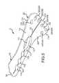
- FIG. 7is a top view of the device of FIG. 1 attached to a radius bone.
- FIG. 8shows top views of a metal support and plastic overlay that can be used to form a different embodiment of the invention.
- FIG. 9shows the plastic overlay of FIG. 8 attached to a metal support.
- FIG. 1shows a top, perspective view of a distal radius plate 10 in accordance with aspects of the invention.
- Distal radius plate 10is preferably comprised of metal, such as stainless steel.
- Plate 10has two main portions: elongated portion 100 and distal radius portion 200 .
- Elongated portion 100has a top side 102 , a bottom side 104 and a distal end (or end) 106 .
- Top side 102is smooth and has a centerline 108 stamped or otherwise formed therein, or centerline 108 could be printed.
- a slot 110is formed in portion 100 and has an upper opening 112 , which is large enough to receive and retain a screw head, and a lower opening 114 , which is large enough for a screw body to pass through and thread into the body of the radius bone, but too small for the screw head to pass through.
- first openings 116Between slot 112 and end 106 are three first openings 116 shown as being centered in elongated portion 100 . Although three openings 116 are shown, one or more first openings 116 may be utilized.
- the purpose of openings 116is for screws to pass through and screw into the radius body thus affixing elongated portion 100 to the elongated body.
- Openings 116are preferably formed at angles so that openings 116 A and 116 C are skewed in one direction by 5°-10°, and preferably 10°, or from 5°-20°.
- Opening 116 Bis preferably skewed in the opposite direction by the same amount. This skewing forces the screws going through the respective openings to enter the radius body at different angles, which makes it more difficult for the elongated portion 100 , and distal radius plate 10 , from rotating.
- End 106is tapered to a rounded edge 106 A and has an inner stop 106 B that prevents it from rotating on the radius body. Stop 106 B is shaped like a hook so if the distal radius plate rotates, the outer edge of the stop presses against the body of the radius bone preventing further rotation.
- Bottom side 104is concave to more easily be fit to and centered on the radius body.
- portion 200is preferably about 1 ⁇ 4′′ to 1 ⁇ 2′′ offset from (or higher than) elongate portion 100 .
- Distal radius portion 200is wide relative elongated portion 100 and is preferably shaped to approximate the shape of the distal radius part of the radius bone. As used herein, the distal radius portion refers to the lower most portion of the radius bone, which is near the wrist. Portion 200 is lower on the radius bone and arm when installed.
- Portion 200has a top surface 202 , a bottom surface 204 , an aperture 206 and a plurality of second openings 208 . Openings 208 as shown are in three sets formed at three different angles. There is a first set 208 A (for large distal radiuses), a second set 208 B for smaller distal radiuses and a third set 208 C for further anchoring to a distal radius of appropriate sizes.
- Fasteners 210fit through the respective openings and are affixed to the distal radius preferably by being threaded into the bone and the fastener heads are countersunk into the openings. A surgeon can determine which openings to place fasteners through depending on the size of the distal radius. Further, the angles of the second openings may permit the fasteners to crisscross, which provides compressive strength.
- Portion 200has an end 212 , a side 214 , and a side 216 .
- End 212 , side 214 and side 216are preferably the same shape of the distal radius for at least 50% of the distance from portion 100 moving towards end 212 , or for at least 75% of the distance from portion 100 moving towards end 212 , or for at least 80% of the distance from portion 100 moving towards end 212 .
- the distal radius plateaccording to various aspects of the invention can be quickly centered and attached, and one size fits most or all radius bones.
- distal radius plate 10In use, an opening is made in the arm and the distal radius plate is centered on the radius bone using concave surface 104 and centerline 108 . Then a fastener is positioned through slot 110 and screwed into the radius body. Distal radius plate 10 can be moved back and forth along slot 110 to properly position portion 200 over the distal radius. The slot also permits limited side-to-side movement to center the distal radius plate.
- a distal radius plate according to the inventionhas a metal support and plastic overlay.
- the metal supportpreferably comprises steel, such as stainless steel.
- the plastic overlaycan be comprised of any suitable material, such as PEEK. The advantage of the plastic overlay is that it reduces production time and costs little or no complex machining of the metal need be performed. Specific embodiments of a distal radius plate with a plastic overlay are described below and shown in some of the attached drawings.
- the metal supportcan simply be stamped using a stamping tool.
- the smooth edges, the distal edge of the elongated portion and the shape of the distal radius portioncan be formed in the plastic made by an injection molding process or another suitable process.
- the first openings and second openingsneed not be machined at angles—they can be punched straight through the metal support.
- the plasticcan partially fill the openings and a surgeon can thread a fastener through the plastic and into the radius bone at any angle he/she desires.
- a plastic overlaymay be manufactured separately and attached to the metal support, for example, by pressure fitting them together. Or, the plastic may be formed over the metal support.
Landscapes
- Health & Medical Sciences (AREA)
- Orthopedic Medicine & Surgery (AREA)
- Surgery (AREA)
- Life Sciences & Earth Sciences (AREA)
- Heart & Thoracic Surgery (AREA)
- Nuclear Medicine, Radiotherapy & Molecular Imaging (AREA)
- Engineering & Computer Science (AREA)
- Biomedical Technology (AREA)
- Neurology (AREA)
- Medical Informatics (AREA)
- Molecular Biology (AREA)
- Animal Behavior & Ethology (AREA)
- General Health & Medical Sciences (AREA)
- Public Health (AREA)
- Veterinary Medicine (AREA)
- Surgical Instruments (AREA)
Abstract
Description
- 1. A distal radius plate having:
- (a) an elongated portion with one or more first openings, the elongated portion for being attached to the body portion of the radius bone; and
- (b) a distal radius portion with one or more second openings, wherein at least some of the openings are formed at outward angle; wherein screws passing through the one or more first openings are received in the body portion and screws passing through the one or more second openings are received in the distal radius.
- 2. The distal radius plate of example 1 wherein there is a upward bend between the elongated portion and the radius portion.
- 3. The distal radius plate of example 2 wherein the radius portion is ¼″ to ½″ above the elongated portion.
- 4. The distal radius plate of any of examples 1-3 that includes a slot in the elongated portion, the slot for receiving a screw to anchor and center the elongated portion on the body portion.
- 5. The distal radius plate of example 4 wherein the slot is between ½″ and 1½″ in length.
- 6. The distal radius plate of any of examples 1-5 wherein there are multiple first openings.
- 7. The distal radius plate of example 6 wherein the elongated portion has an end distal the distal radius portion and an end proximal the distal radius portion and each of the first openings is between the distal end and the slot.
- 8. The distal radius plate of any of examples 1-7 wherein the elongated portion has a visible center line to assist in centering the distal radius plate on the radius bone.
- 9. The distal radius plate of any of examples 1-8 wherein the elongated portion has an end distal the distal radius portion and the distal end is tapered to form a rounded edge.
- 10. The distal radius plate of any of examples 1-9 wherein the distal radius portion has different second openings formed at different angles in order to accommodate different-sized distal radiuses.
- 11. The distal radius plate of any of examples 1-10 wherein the distal radius portion has an enlarged opening between the second openings and the elongated portion.
- 12. The distal radius plate of example 10 wherein there is a first set of second openings to fit one sized hand and a second set of second openings to fit a different sized hand, wherein the first set of second openings are formed at different angles than the second set of second openings.
- 13. The distal radius plate of any of examples 1-12 wherein each of the second openings has a locking mechanism to hold a fastener in place.
- 14. The distal radius plate of any of examples 1-13 wherein the shape and size of the distal radius portion enables it to self center on the distal radius bone.
- 15. The distal radius plate of any of examples 1-13 wherein the distal radius portion has the shape of the distal radius.
- 16. The distal radius plate of any of examples 1-15 wherein the at least two second openings are positioned such that at least one bone portion in the distal radius can be engaged by at least two fasteners.
- 17. The distal radius plate of any of examples 1-15 wherein the second openings are positioned such that more than one bone portion in the distal radius can be engaged by more than one fastener.
- 18. The distal radius plate of any of examples 1-17 wherein the elongated portion has a top surface, and a bottom surface that rests against the body of the radius bone, the bottom surface being concave.
- 19. The distal radius plate of any of examples 1-18 wherein the elongated portion has an end distal the distal radius portion and the distal end has a flange.
- 20. The distal radius plate of any of examples 1-19 wherein there is a first set of second openings to fit one sized hand and a second set of second openings to fit a different sized hand, wherein the first set of openings are positioned farther from the center of the distal radius portion than the second set of openings.
- 21. The distal radius plate of any of examples 1-20 wherein at least the upper half of the distal radius portion is shaped the same as the distal radius bone.
- 22. The distal radius plate of any of examples 1-20 wherein at least the upper 75% of the distal radius portion is shaped the same as the distal radius.
- 23. The distal radius plate of any of examples 1-22 wherein the bottom of the elongated portion has a stop including a ridge to prevent rotation.
- 24. The distal radius plate of example 23 wherein the stop is at the end of the elongated portion distal from the distal radius portion.
- 25. The distal radius plate of example 4 wherein the slot accepts a screw that is threaded into the radius bone body and the distal radius plate can slide along the radius bone with the screw maintaining the side-to-side position of the distal radius plate.
Claims (22)
Priority Applications (2)
| Application Number | Priority Date | Filing Date | Title |
|---|---|---|---|
| US15/146,824US10441330B2 (en) | 2015-05-19 | 2016-05-04 | Distal radius plate |
| US16/596,315US11185357B2 (en) | 2015-05-19 | 2019-10-08 | Distal radius plate |
Applications Claiming Priority (2)
| Application Number | Priority Date | Filing Date | Title |
|---|---|---|---|
| US201562163912P | 2015-05-19 | 2015-05-19 | |
| US15/146,824US10441330B2 (en) | 2015-05-19 | 2016-05-04 | Distal radius plate |
Related Child Applications (1)
| Application Number | Title | Priority Date | Filing Date |
|---|---|---|---|
| US16/596,315ContinuationUS11185357B2 (en) | 2015-05-19 | 2019-10-08 | Distal radius plate |
Publications (2)
| Publication Number | Publication Date |
|---|---|
| US20160338748A1 US20160338748A1 (en) | 2016-11-24 |
| US10441330B2true US10441330B2 (en) | 2019-10-15 |
Family
ID=56087505
Family Applications (2)
| Application Number | Title | Priority Date | Filing Date |
|---|---|---|---|
| US15/146,824ActiveUS10441330B2 (en) | 2015-05-19 | 2016-05-04 | Distal radius plate |
| US16/596,315Active2036-10-30US11185357B2 (en) | 2015-05-19 | 2019-10-08 | Distal radius plate |
Family Applications After (1)
| Application Number | Title | Priority Date | Filing Date |
|---|---|---|---|
| US16/596,315Active2036-10-30US11185357B2 (en) | 2015-05-19 | 2019-10-08 | Distal radius plate |
Country Status (2)
| Country | Link |
|---|---|
| US (2) | US10441330B2 (en) |
| WO (1) | WO2016186847A1 (en) |
Cited By (2)
| Publication number | Priority date | Publication date | Assignee | Title |
|---|---|---|---|---|
| US11185357B2 (en) | 2015-05-19 | 2021-11-30 | ExsoMed Corporation | Distal radius plate |
| US11259849B2 (en) | 2013-10-02 | 2022-03-01 | ExsoMed Corporation | Full wrist fusion device |
Families Citing this family (10)
| Publication number | Priority date | Publication date | Assignee | Title |
|---|---|---|---|---|
| US9480515B2 (en) | 2012-07-12 | 2016-11-01 | Exsomed International IP, LLC | Metacarpal bone stabilization device |
| US9622523B2 (en) | 2014-01-06 | 2017-04-18 | Exsomed International IP, LLC | Ergonomic work gloves |
| US10245091B2 (en) | 2015-12-30 | 2019-04-02 | Exsomed Holding Company, Llc | Dip fusion spike screw |
| US11147604B2 (en) | 2016-01-12 | 2021-10-19 | ExsoMed Corporation | Bone stabilization device |
| US10194923B2 (en) | 2016-05-10 | 2019-02-05 | Exsomed International IP, LLC | Tool for percutaneous joint cartilage destruction and preparation for joint fusion |
| US11191645B2 (en) | 2017-09-05 | 2021-12-07 | ExsoMed Corporation | Small bone tapered compression screw |
| JP2020532407A (en) | 2017-09-05 | 2020-11-12 | エクソームド コーポレーションExsomed Corporation | Threaded intramedullary nail for radial cortex fixation |
| US11147681B2 (en) | 2017-09-05 | 2021-10-19 | ExsoMed Corporation | Small bone angled compression screw |
| EP4342398A3 (en)* | 2020-05-19 | 2024-05-29 | Smith & Nephew, Inc. | Periprosthetic bone plate |
| EP4514250A2 (en)* | 2022-04-28 | 2025-03-05 | Paragon 28, Inc. | Orthopedic implants, instrument systems and methods of use |
Citations (172)
| Publication number | Priority date | Publication date | Assignee | Title |
|---|---|---|---|---|
| US1741279A (en) | 1927-04-20 | 1929-12-31 | William C Bowman | Staple |
| US2037586A (en) | 1934-06-27 | 1936-04-14 | Illinois Tool Works | Locking means for threaded elements |
| US2210455A (en) | 1938-05-31 | 1940-08-06 | Illinois Tool Works | Lock nut |
| US2217951A (en) | 1938-07-29 | 1940-10-15 | Illinois Tool Works | Self-locking screw |
| US2229892A (en) | 1939-03-20 | 1941-01-28 | Illinois Tool Works | Self-locking screw |
| US2242003A (en) | 1940-06-13 | 1941-05-13 | Frank A Lorenzo | Method and apparatus for reduction of fracture of femur |
| US3078900A (en) | 1959-11-02 | 1963-02-26 | Robert H Walker | Flanged nut with reinforced deflecting prongs |
| US3275055A (en) | 1964-02-04 | 1966-09-27 | Illinois Tool Works | Bolt and washer assembly with cooperating pawl and ratchet means |
| US3397699A (en) | 1966-05-05 | 1968-08-20 | Gerald C. Kohl | Retaining catheter having resiliently biased wing flanges |
| US3717146A (en) | 1971-02-01 | 1973-02-20 | W Halloran | Threaded intramedullary compression and fixation device |
| US4016874A (en) | 1976-05-19 | 1977-04-12 | Maffei Ernest J | Three-part intramedullary bone-setting pin |
| DE2713386A1 (en) | 1977-03-23 | 1978-11-02 | Vaubel Wolf Eckehard Prof Dr | Flexible sinew-holding pliers for hand surgery - has tube with spring loaded holding claws of high flexibility |
| GB2007099A (en) | 1977-11-02 | 1979-05-16 | Hamas R S | Total wrist prosthetic device |
| US4175555A (en) | 1977-02-24 | 1979-11-27 | Interfix Limited | Bone screw |
| US4350465A (en) | 1980-04-28 | 1982-09-21 | Industrial Fasteners Corp. | Spider washer head screw |
| US4380414A (en) | 1979-04-04 | 1983-04-19 | The Lamson & Sessions Co. | Fastener |
| CH643131A5 (en) | 1981-08-03 | 1984-05-30 | Jaquet Orthopedie | Transcutaneous pin for fixation of a bone fragment or element |
| US4463753A (en) | 1980-01-04 | 1984-08-07 | Gustilo Ramon B | Compression bone screw |
| US4471777A (en) | 1983-03-30 | 1984-09-18 | Mccorkle Jr Charles E | Endocardial lead extraction apparatus and method |
| CH646858A5 (en) | 1980-11-20 | 1984-12-28 | S & T Marketing Ag | Forceps for holding a nerve tract |
| US4584722A (en) | 1982-05-24 | 1986-04-29 | Yeda Research And Development Co., Ltd. | Prosthetic tendon |
| US4608965A (en) | 1985-03-27 | 1986-09-02 | Anspach Jr William E | Endoscope retainer and tissue retracting device |
| GB2181356A (en) | 1985-10-15 | 1987-04-23 | Univ New Mexico | Surgical clip and tool therefor |
| US4764066A (en) | 1985-04-22 | 1988-08-16 | Farley Metals, Inc. | Light gauge self-tapping sheet metal screw |
| US4781191A (en) | 1987-01-20 | 1988-11-01 | Thompson James S | Method for enabling atraumatic passage of a severed tendon through a tendon sheath |
| US4812095A (en) | 1987-02-24 | 1989-03-14 | Emhart Industries, Inc. | Threaded fastener |
| US4820235A (en) | 1987-07-28 | 1989-04-11 | Hirsh Company | Threaded fastener |
| US4842463A (en) | 1984-12-10 | 1989-06-27 | Sps Technologies, Inc. | Vibration resistant fasteners |
| US4901717A (en) | 1987-01-05 | 1990-02-20 | Moore Robert R | Tendon leader |
| US4909789A (en) | 1986-03-28 | 1990-03-20 | Olympus Optical Co., Ltd. | Observation assisting forceps |
| US5061283A (en) | 1987-10-30 | 1991-10-29 | Pfizer Hospital Products Group, Inc. | Method for tendon and ligament repair |
| US5234299A (en) | 1987-08-03 | 1993-08-10 | Giannuzzi Louis | Self-drilling anchor |
| US5312255A (en) | 1989-06-05 | 1994-05-17 | Ernst Bauer | Screw implant for a jawbone |
| EP0597223A1 (en) | 1992-10-09 | 1994-05-18 | United States Surgical Corporation | Surgical apparatus for removing fasteners |
| US5345927A (en) | 1990-03-02 | 1994-09-13 | Bonutti Peter M | Arthroscopic retractors |
| US5443466A (en) | 1991-12-13 | 1995-08-22 | Shah; Mrugesh K. | Method and apparatus for treating fractures of a bone |
| US5522846A (en) | 1993-05-14 | 1996-06-04 | Bonutti; Peter M. | Suture anchor |
| US5645545A (en) | 1995-08-14 | 1997-07-08 | Zimmer, Inc. | Self reaming intramedullary nail and method for using the same |
| US5667510A (en) | 1995-08-03 | 1997-09-16 | Combs; C. Robert | Joint fixation system and method |
| WO1997033537A1 (en) | 1996-03-13 | 1997-09-18 | Bramlet Dale G | Arthroplasty joint assembly |
| US5690633A (en) | 1994-09-23 | 1997-11-25 | Smith & Nephew Richards, Inc. | Orthopedic fracture fixation device |
| US5840078A (en) | 1995-03-01 | 1998-11-24 | Yerys; Paul | Method and apparatus for mechanical attachment of soft tissue to bone tissue |
| US5853413A (en) | 1997-04-18 | 1998-12-29 | Bristol-Myers Squibb Company | Wrist fusion plate |
| US6187007B1 (en) | 1996-07-31 | 2001-02-13 | Synthes (Usa) | Device for attaching fractured hip-joint heads |
| US6221006B1 (en) | 1998-02-10 | 2001-04-24 | Artemis Medical Inc. | Entrapping apparatus and method for use |
| US6231413B1 (en) | 1995-01-31 | 2001-05-15 | Canon Kabushiki Kaisha | Electron-emitting device as well as electron source and image-forming apparatus using such devices |
| US6231319B1 (en) | 1998-02-13 | 2001-05-15 | Matsushita Electric Industrial Co., Ltd. | Hermetic compressor |
| US6306140B1 (en) | 2001-01-17 | 2001-10-23 | Synthes (Usa) | Bone screw |
| US20010049529A1 (en) | 1996-11-12 | 2001-12-06 | Cachia Victor V. | Bone fixation system |
| US20020045897A1 (en) | 2000-10-16 | 2002-04-18 | Dixon Robert A. | Method and apparatus utilizing interference fit screw shanks for nonmetallic spinal stabilization |
| US20020055749A1 (en) | 1997-02-25 | 2002-05-09 | Philip Stuart Esnouf | Surgical aid for connective tissue grafting and method for employing same |
| US20020055747A1 (en) | 2000-11-09 | 2002-05-09 | Metamorphic Surgical Devices, Llc | Apparatus for capturing objects beyond an operative site utilizing a capture device delivered on a medical guide wire |
| US6394725B1 (en) | 1999-02-23 | 2002-05-28 | Robert Dicke | Countersunk head screw |
| US20020143337A1 (en) | 2000-02-01 | 2002-10-03 | Hand Innovations, Inc. | Fixation device for metaphyseal long bone fractures |
| US20020198527A1 (en) | 2001-06-21 | 2002-12-26 | Helmut Muckter | Implantable screw for stabilization of a joint or a bone fracture |
| US20030014077A1 (en) | 2001-06-29 | 2003-01-16 | Leung Jeffrey C. | Suture method |
| US6517541B1 (en) | 1998-12-23 | 2003-02-11 | Nenad Sesic | Axial intramedullary screw for the osteosynthesis of long bones |
| US20030083661A1 (en) | 2000-02-01 | 2003-05-01 | Hand Innovations, Inc. | Intramedullary fixation device for metaphyseal long bone fractures and methods of using the same |
| US20030130735A1 (en) | 2002-01-09 | 2003-07-10 | Roger Rogalski | Graft device and methods of use |
| US6592623B1 (en) | 1999-08-31 | 2003-07-15 | Virginia Commonwealth University Intellectual Property Foundation | Engineered muscle |
| US6607530B1 (en) | 1999-05-10 | 2003-08-19 | Highgate Orthopedics, Inc. | Systems and methods for spinal fixation |
| EP1378205A1 (en) | 2002-07-05 | 2004-01-07 | Newdeal S.A. | Compression screw for osteosynthesis |
| US20040193217A1 (en) | 1996-09-13 | 2004-09-30 | Tendon Technology, Ltd. | Apparatus and methods for tendon or ligament repair |
| US20040210227A1 (en) | 2003-02-03 | 2004-10-21 | Kinetikos Medical, Inc. | Compression screw apparatuses, systems and methods |
| US6808526B1 (en) | 1998-07-13 | 2004-10-26 | Sepitec Foundation | Osteosynthesis screw, especially for application by a translaminar vertebral screw |
| WO2004093700A1 (en) | 2003-04-23 | 2004-11-04 | Dugal Simon Stewart James | A fixation device and method of fixation |
| US20040260288A1 (en) | 2003-06-20 | 2004-12-23 | Means Robert Earl | Slipped capital femoral epiphysis fixation screw (SCFEFS) |
| US20050075642A1 (en) | 2001-12-19 | 2005-04-07 | Felt Jeffrey C. | Bone smoothing method and system |
| US20050085824A1 (en) | 2003-10-15 | 2005-04-21 | Hand Innovations, Inc. | JIG assembly for implantation of a fracture fixation device |
| US20050107791A1 (en) | 2003-11-14 | 2005-05-19 | Manderson Easton L. | Intramedullary locked compression screw for stabiliziation and union of complex ankle and subtalar deformities |
| US20050143735A1 (en) | 2003-04-29 | 2005-06-30 | Kyle Richard F. | Double compression unloadable screw system |
| WO2005092226A1 (en) | 2004-03-26 | 2005-10-06 | Synthes Gmbh | Articulated bone screw |
| US7037309B2 (en) | 2001-07-05 | 2006-05-02 | Depuy (Ireland) Limted | Self-tapping screw for small-bone surgery |
| US7041106B1 (en) | 2001-06-15 | 2006-05-09 | Biomet, Inc. | Interphalangeal fusion pin |
| US20060129153A1 (en) | 2003-04-10 | 2006-06-15 | Kaj Klaue | Device for temporarily splinting toes |
| US7063491B2 (en) | 2003-06-11 | 2006-06-20 | French Douglas R | Reverse barb system for screws and nails |
| US20060149249A1 (en) | 2002-12-11 | 2006-07-06 | Christophe Mathoulin | Osteosynthesis plate for the osteosynthesis of small neighbouring bones |
| US20060165506A1 (en) | 2004-02-05 | 2006-07-27 | Panasik Cheryl L | Anchor |
| US20060195099A1 (en) | 2005-02-15 | 2006-08-31 | Apex Abc, Llc | Bone screw for positive locking but flexible engagement to a bone |
| WO2006105935A1 (en) | 2005-04-04 | 2006-10-12 | Zimmer Gmbh | Pedicle screw |
| US20060271061A1 (en) | 2001-07-25 | 2006-11-30 | Disc-O-Tech, Ltd. | Deformable tools and implants |
| US20060276790A1 (en) | 2005-06-02 | 2006-12-07 | Zimmer Spine, Inc. | Minimally invasive facet joint repair |
| US20070027547A1 (en) | 2003-06-27 | 2007-02-01 | Advanced Bio Surfaces, Inc. | System and method for ankle arthroplasty |
| US20070135816A1 (en) | 2005-11-21 | 2007-06-14 | Ist Innovative Shoulder Technology Ag | Bone anchor |
| WO2007081601A2 (en) | 2006-01-10 | 2007-07-19 | Southern Illinois University | Material retrieval device and method of using |
| WO2007109140A2 (en) | 2006-03-17 | 2007-09-27 | Nexa Orthopedics, Inc. | Bone screw with selectively securable washer |
| US20070299449A1 (en) | 2006-06-06 | 2007-12-27 | Bioretec Oy | Bone fixation device |
| US7334976B2 (en) | 2003-09-05 | 2008-02-26 | A—Z Ausrustung und Zubehor GmbH & Co. KG | Countersunk screw |
| WO2008063156A2 (en) | 2006-10-26 | 2008-05-29 | Chestnut Medical Technologies, Inc. | Intracorporeal grasping device |
| DE102007003645A1 (en) | 2007-01-22 | 2008-07-24 | Somatex Medical Technologies Gmbh | Damaged bone structures i.e. vertebral body, treating instrument for use during e.g. osteoporosis treatment, has elongate opening enabling expansion of barrel surface during force exertion in proximal-axial direction on cylinder distal end |
| US20080183220A1 (en) | 2007-01-19 | 2008-07-31 | Glazer Paul A | Orthopedic screw insert |
| US20080219801A1 (en) | 2007-03-09 | 2008-09-11 | Nissan Technical Center North America, Inc. | Screw Fastener |
| US20080249547A1 (en) | 2005-11-02 | 2008-10-09 | University Of Massachusetts | Tissue clamp |
| US20080249574A1 (en) | 2007-03-20 | 2008-10-09 | Mccombs Mary | Bone Screw System |
| US7465135B2 (en) | 2003-11-14 | 2008-12-16 | Maclean-Fogg Company | U-Nut fastening assembly |
| US7507242B2 (en) | 2004-06-02 | 2009-03-24 | Facet Solutions | Surgical measurement and resection framework |
| US7604659B2 (en) | 2004-11-09 | 2009-10-20 | Lee James M | Method and apparatus for repair of torn rotator cuff tendons |
| US20090299369A1 (en) | 2008-06-02 | 2009-12-03 | Skeletal Dynamics Llc | Hybrid Orthopedic Implant |
| US20100106254A1 (en) | 2008-10-23 | 2010-04-29 | Delsignore Jeanne L | Surgical implantable stabilizer sling for basal joint arthroplasty |
| US20100121136A1 (en) | 2008-06-08 | 2010-05-13 | Lloyd Champagne | Methods and apparatus for capturing and manipulating body parts |
| US20100130978A1 (en) | 2008-09-17 | 2010-05-27 | Skeletal Dynamics Llc | Intramedullary Arthrodesis Nail and Method of Use |
| US7766942B2 (en)* | 2006-08-31 | 2010-08-03 | Warsaw Orthopedic, Inc. | Polymer rods for spinal applications |
| US20100211115A1 (en) | 2008-12-24 | 2010-08-19 | Jeff Tyber | Compression screw assembly, an orthopedic fixation system including a compression screw assembly and method of use |
| US20100278614A1 (en) | 2007-12-12 | 2010-11-04 | Excalibar Screwbolts Limited | Fixing device |
| US20100312286A1 (en) | 2007-10-30 | 2010-12-09 | Dell Oca Alberto A Fernandez | Variable Angle Locked Bone Plate |
| US20100324556A1 (en) | 2008-06-24 | 2010-12-23 | Jeff Tyber | Fixation system, an intramedullary fixation assembly and method of use |
| WO2010151589A1 (en) | 2009-06-23 | 2010-12-29 | Replication Medical, Inc. | Trapezium prosthesis |
| US20110009865A1 (en) | 2009-07-13 | 2011-01-13 | Orfaly Robert M | Bone fixation using an intramedullary pin |
| US20110130794A1 (en) | 2009-11-27 | 2011-06-02 | Rahul Vaidya | Method and Apparatus for Minimally Invasive Subcutaneous Treatment of Long Bone Fractures |
| US7988724B2 (en) | 2003-12-23 | 2011-08-02 | Sadra Medical, Inc. | Systems and methods for delivering a medical implant |
| US8011866B2 (en) | 2001-08-20 | 2011-09-06 | Maclean-Fogg Company | Locking fastener assembly |
| US20120083847A1 (en) | 2010-10-05 | 2012-04-05 | Huebner Randall J | Fastener with serrated thread for attachment to a bone plate at a selectable angle |
| US8157803B1 (en) | 2007-08-21 | 2012-04-17 | Surgical Implant Generation Network | Bone fixation using an intramedullary nail interlocked with a buttress member |
| WO2012050424A1 (en)* | 2010-10-14 | 2012-04-19 | Sai Yeong Leong | A distal radius plating system |
| US20120136398A1 (en) | 2010-05-28 | 2012-05-31 | Jean-Pierre Mobasser | Awl-tipped pedicle screw and method of implanting same |
| US20120191140A1 (en) | 1998-02-06 | 2012-07-26 | Bonutti Peter M | Apparatus and method for securing a portion of a body |
| US20120221104A1 (en) | 2009-09-11 | 2012-08-30 | Allergan, Inc. | Prosthetic device and method of manufacturing the same |
| US20120253464A1 (en) | 2003-06-30 | 2012-10-04 | Depuy Mitek, Inc. | Scaffold for connective tissue repair |
| US20120253465A1 (en) | 2011-03-31 | 2012-10-04 | Biomet Manufacturing Corp | Dual Tendon Bundle |
| US8348575B2 (en) | 2008-12-19 | 2013-01-08 | Illinois Tool Works Inc. | Self-counter-sinking screw with circumferential cutters |
| US20130012987A1 (en) | 2010-04-11 | 2013-01-10 | Strategic Capital LLC | Implantable biodegradable wound closure device and method |
| US20130053961A1 (en) | 2008-03-27 | 2013-02-28 | The Cleveland Clinic Foundation | Reinforced tissue graft |
| US20130060333A1 (en) | 2011-09-01 | 2013-03-07 | Eduardo Gonzalez-Hernandez | Tendon crimp for passage into a bone tunnel and method for use thereof |
| US8398687B2 (en)* | 2006-12-06 | 2013-03-19 | Amei Technologies, Inc. | Volar plate fixation device |
| US8414648B2 (en) | 2004-08-09 | 2013-04-09 | Si-Bone Inc. | Apparatus, systems, and methods for achieving trans-iliac lumbar fusion |
| US8419776B2 (en)* | 2010-03-08 | 2013-04-16 | Memometal Technologies | Radius-plate assembly |
| US20130131699A1 (en) | 2011-11-18 | 2013-05-23 | Zimmer, Inc. | Porous metal device for regenerating soft tissue-to-bone interface |
| US20130138123A1 (en) | 2006-02-03 | 2013-05-30 | Biomet Sports Medicine, Llc | Method And Apparatus For Coupling Soft Tissue To A Bone |
| EP2606843A1 (en) | 2011-12-22 | 2013-06-26 | Stryker Trauma SA | Wrist fusion plate |
| US20130190872A1 (en) | 2008-04-30 | 2013-07-25 | Moximed, Inc. | Sheaths for extra-articular implantable systems |
| US20130197592A1 (en) | 2012-01-27 | 2013-08-01 | Kyphon Sarl | Anchoring cannula |
| US8518042B2 (en)* | 2010-10-19 | 2013-08-27 | Biomet Manufacturing, Llc | Orthopedic plate assembly for a distal radius having re-contouring features and method for using same |
| US20130245700A1 (en) | 2012-03-14 | 2013-09-19 | Ronald J. Choinski | Cmc repair using suture-button construct |
| US20130245762A1 (en) | 2010-03-11 | 2013-09-19 | Craig Van Kampen | Tendon repair implant and method of arthroscopic implantation |
| US20130245626A1 (en) | 2011-09-08 | 2013-09-19 | Abraham Lavi | Intramedullary Nail and Nail Combinations |
| US20130261662A1 (en) | 2005-05-04 | 2013-10-03 | Joerg Mayer | Joining element |
| US20130274879A1 (en) | 2012-01-23 | 2013-10-17 | Lloyd P. Champagne | Devices and methods for tendon repair |
| US20130282058A1 (en) | 2006-02-01 | 2013-10-24 | Arthrex, Inc. | Method for double row fixation of tendon to bone |
| US8568462B2 (en)* | 2007-11-02 | 2013-10-29 | Biomet C.V. | Bone plate system with two different types of drill guides |
| US8597337B2 (en) | 2008-02-14 | 2013-12-03 | Lloyd P. Champagne | Joint fusion device |
| US20130325011A1 (en) | 2012-06-04 | 2013-12-05 | Depuy Mitek, Inc. | Methods and Devices for Forming Bone Tunnels |
| US8608783B2 (en)* | 2008-05-08 | 2013-12-17 | The Cleveland Clinic Foundation | Bone plate with flange member and methods of use thereof |
| WO2014011933A1 (en) | 2012-07-12 | 2014-01-16 | Exsomed Holding Company Llc | Metacarpal bone stabilization device |
| US20140067063A1 (en) | 2004-10-26 | 2014-03-06 | P Tech, Llc | Devices and methods for stabilizing tissue and implants |
| WO2014089524A1 (en) | 2012-12-06 | 2014-06-12 | Microsoft Corporation | Communication context based predictive-text suggestion |
| DE202013101135U1 (en) | 2013-03-15 | 2014-06-17 | Zimmer Gmbh | Surgical locking screw |
| US8814918B2 (en)* | 2011-02-14 | 2014-08-26 | Skeletal Dynamics, L.L.C. | Fracture fixation plate |
| US20140257349A1 (en) | 2012-07-20 | 2014-09-11 | Anthony E. Sudekum | Terminal tissue attachment and repair device |
| US20140276846A1 (en) | 2013-03-15 | 2014-09-18 | Richard G. Mauldin | Systems and methods for implanting bone graft and implant |
| US8864804B2 (en) | 2008-02-14 | 2014-10-21 | Lloyd P. Champagne | Bent dip fusion screw |
| US20140336712A1 (en) | 2006-03-07 | 2014-11-13 | Orthohelix Surgical Designs, Inc. | Orthopedic plate |
| US8888429B2 (en) | 2009-12-22 | 2014-11-18 | Jpmorgan Chase Bank, N.A. | Nut with lug flare |
| US8906075B2 (en)* | 2010-07-14 | 2014-12-09 | DePuy Synthes Products, LLC | Methods and assemblies for aligning a bone fixation plate |
| US20150066060A1 (en) | 1999-12-02 | 2015-03-05 | Smith & Nephew, Inc. | Methods for Tissue Repair |
| US20150094722A1 (en) | 2013-10-02 | 2015-04-02 | Exsomed Holding Company Llc | Full wrist fusion device |
| US20150094724A1 (en) | 2013-10-02 | 2015-04-02 | Exsomed Holding Company Llc | Joint scrubber |
| US20150094777A1 (en) | 2013-10-02 | 2015-04-02 | Exsomed Holding Company Llc | Bone screw |
| WO2015050900A1 (en) | 2013-10-02 | 2015-04-09 | Exsomed Holding Company Llc | Scaphoid screws and fasteners |
| WO2015050902A1 (en) | 2013-10-02 | 2015-04-09 | Exsomed Holding Company Llc | Carpal metacarpal support device |
| WO2015050896A1 (en) | 2013-10-02 | 2015-04-09 | Exsomed Holding Company Llc | Nerve coupler |
| US9046120B2 (en) | 2010-10-01 | 2015-06-02 | Infastech Intellectual Properties Pte. Ltd | Threaded fastener |
| US9086088B2 (en) | 2009-09-17 | 2015-07-21 | Illinois Tool Works Inc. | Screw having underside cutters and pockets |
| US9175715B2 (en) | 2011-07-21 | 2015-11-03 | Profil Verbindungstechnik Gmbh & Co. Kg | Functional element having features providing security against rotation and also a component assembly consisting of the functional element and a sheet metal part |
| US9265600B2 (en) | 2013-02-27 | 2016-02-23 | Orthopediatrics Corp. | Graft fixation |
| US20160256290A1 (en) | 2015-03-03 | 2016-09-08 | Restore Surgical Llc, Dba Instratek | Orthopedic implant and methods of implanting and removing same |
| WO2016186847A1 (en) | 2015-05-19 | 2016-11-24 | Exsomed International IP, LLC | Distal radius plate |
| US20170027577A1 (en) | 2012-07-30 | 2017-02-02 | Conextions, Inc. | Soft tissue repair devices, systems, and methods |
| US20170049167A1 (en) | 2014-01-06 | 2017-02-23 | Exsomed International IP, LLC | Gloves with sensory windows |
| US20170189090A1 (en) | 2015-12-30 | 2017-07-06 | Exsomed International IP, LLC | Dip fusion spike screw |
| US20170196609A1 (en) | 2016-01-12 | 2017-07-13 | Exsomed International IP, LLC | Bone stabilization device |
| US20170325827A1 (en) | 2016-05-10 | 2017-11-16 | Exsomed International IP, LLC | Tool for percutaneous joint cartilage destruction and preparation for joint fusion |
| US20180021124A1 (en) | 2016-07-19 | 2018-01-25 | Exsomed International IP, LLC | Body part support device and method |
Family Cites Families (3)
| Publication number | Priority date | Publication date | Assignee | Title |
|---|---|---|---|---|
| US4653487A (en) | 1986-01-29 | 1987-03-31 | Maale Gerhard E | Intramedullary rod assembly for cement injection system |
| US8709092B2 (en) | 2011-02-16 | 2014-04-29 | Genesis Medical Devices, LLC | Periprosthetic fracture management enhancements |
| US9974611B2 (en) | 2012-12-06 | 2018-05-22 | Exomed International Ip, Llc | Ergonomic surgical glove |
- 2016
- 2016-05-04WOPCT/US2016/030850patent/WO2016186847A1/ennot_activeCeased
- 2016-05-04USUS15/146,824patent/US10441330B2/enactiveActive
- 2019
- 2019-10-08USUS16/596,315patent/US11185357B2/enactiveActive
Patent Citations (191)
| Publication number | Priority date | Publication date | Assignee | Title |
|---|---|---|---|---|
| US1741279A (en) | 1927-04-20 | 1929-12-31 | William C Bowman | Staple |
| US2037586A (en) | 1934-06-27 | 1936-04-14 | Illinois Tool Works | Locking means for threaded elements |
| US2210455A (en) | 1938-05-31 | 1940-08-06 | Illinois Tool Works | Lock nut |
| US2217951A (en) | 1938-07-29 | 1940-10-15 | Illinois Tool Works | Self-locking screw |
| US2229892A (en) | 1939-03-20 | 1941-01-28 | Illinois Tool Works | Self-locking screw |
| US2242003A (en) | 1940-06-13 | 1941-05-13 | Frank A Lorenzo | Method and apparatus for reduction of fracture of femur |
| US3078900A (en) | 1959-11-02 | 1963-02-26 | Robert H Walker | Flanged nut with reinforced deflecting prongs |
| US3275055A (en) | 1964-02-04 | 1966-09-27 | Illinois Tool Works | Bolt and washer assembly with cooperating pawl and ratchet means |
| US3397699A (en) | 1966-05-05 | 1968-08-20 | Gerald C. Kohl | Retaining catheter having resiliently biased wing flanges |
| US3717146A (en) | 1971-02-01 | 1973-02-20 | W Halloran | Threaded intramedullary compression and fixation device |
| US4016874A (en) | 1976-05-19 | 1977-04-12 | Maffei Ernest J | Three-part intramedullary bone-setting pin |
| US4175555A (en) | 1977-02-24 | 1979-11-27 | Interfix Limited | Bone screw |
| DE2713386A1 (en) | 1977-03-23 | 1978-11-02 | Vaubel Wolf Eckehard Prof Dr | Flexible sinew-holding pliers for hand surgery - has tube with spring loaded holding claws of high flexibility |
| GB2007099A (en) | 1977-11-02 | 1979-05-16 | Hamas R S | Total wrist prosthetic device |
| US4380414A (en) | 1979-04-04 | 1983-04-19 | The Lamson & Sessions Co. | Fastener |
| US4463753A (en) | 1980-01-04 | 1984-08-07 | Gustilo Ramon B | Compression bone screw |
| US4350465A (en) | 1980-04-28 | 1982-09-21 | Industrial Fasteners Corp. | Spider washer head screw |
| CH646858A5 (en) | 1980-11-20 | 1984-12-28 | S & T Marketing Ag | Forceps for holding a nerve tract |
| CH643131A5 (en) | 1981-08-03 | 1984-05-30 | Jaquet Orthopedie | Transcutaneous pin for fixation of a bone fragment or element |
| US4584722A (en) | 1982-05-24 | 1986-04-29 | Yeda Research And Development Co., Ltd. | Prosthetic tendon |
| US4471777A (en) | 1983-03-30 | 1984-09-18 | Mccorkle Jr Charles E | Endocardial lead extraction apparatus and method |
| US4842463A (en) | 1984-12-10 | 1989-06-27 | Sps Technologies, Inc. | Vibration resistant fasteners |
| US4608965A (en) | 1985-03-27 | 1986-09-02 | Anspach Jr William E | Endoscope retainer and tissue retracting device |
| US4764066A (en) | 1985-04-22 | 1988-08-16 | Farley Metals, Inc. | Light gauge self-tapping sheet metal screw |
| GB2181356A (en) | 1985-10-15 | 1987-04-23 | Univ New Mexico | Surgical clip and tool therefor |
| US4909789A (en) | 1986-03-28 | 1990-03-20 | Olympus Optical Co., Ltd. | Observation assisting forceps |
| US4901717A (en) | 1987-01-05 | 1990-02-20 | Moore Robert R | Tendon leader |
| US4781191A (en) | 1987-01-20 | 1988-11-01 | Thompson James S | Method for enabling atraumatic passage of a severed tendon through a tendon sheath |
| US4812095A (en) | 1987-02-24 | 1989-03-14 | Emhart Industries, Inc. | Threaded fastener |
| US4820235A (en) | 1987-07-28 | 1989-04-11 | Hirsh Company | Threaded fastener |
| US5234299A (en) | 1987-08-03 | 1993-08-10 | Giannuzzi Louis | Self-drilling anchor |
| US5061283A (en) | 1987-10-30 | 1991-10-29 | Pfizer Hospital Products Group, Inc. | Method for tendon and ligament repair |
| US5312255A (en) | 1989-06-05 | 1994-05-17 | Ernst Bauer | Screw implant for a jawbone |
| US5345927A (en) | 1990-03-02 | 1994-09-13 | Bonutti Peter M | Arthroscopic retractors |
| US5443466A (en) | 1991-12-13 | 1995-08-22 | Shah; Mrugesh K. | Method and apparatus for treating fractures of a bone |
| EP0597223A1 (en) | 1992-10-09 | 1994-05-18 | United States Surgical Corporation | Surgical apparatus for removing fasteners |
| US5522846A (en) | 1993-05-14 | 1996-06-04 | Bonutti; Peter M. | Suture anchor |
| US5690633A (en) | 1994-09-23 | 1997-11-25 | Smith & Nephew Richards, Inc. | Orthopedic fracture fixation device |
| US6231413B1 (en) | 1995-01-31 | 2001-05-15 | Canon Kabushiki Kaisha | Electron-emitting device as well as electron source and image-forming apparatus using such devices |
| US5840078A (en) | 1995-03-01 | 1998-11-24 | Yerys; Paul | Method and apparatus for mechanical attachment of soft tissue to bone tissue |
| US5667510A (en) | 1995-08-03 | 1997-09-16 | Combs; C. Robert | Joint fixation system and method |
| US5645545A (en) | 1995-08-14 | 1997-07-08 | Zimmer, Inc. | Self reaming intramedullary nail and method for using the same |
| US6475242B1 (en) | 1996-03-13 | 2002-11-05 | Dale G. Bramlet | Arthroplasty joint assembly |
| WO1997033537A1 (en) | 1996-03-13 | 1997-09-18 | Bramlet Dale G | Arthroplasty joint assembly |
| US6187007B1 (en) | 1996-07-31 | 2001-02-13 | Synthes (Usa) | Device for attaching fractured hip-joint heads |
| US20040193217A1 (en) | 1996-09-13 | 2004-09-30 | Tendon Technology, Ltd. | Apparatus and methods for tendon or ligament repair |
| US20010049529A1 (en) | 1996-11-12 | 2001-12-06 | Cachia Victor V. | Bone fixation system |
| US20020055749A1 (en) | 1997-02-25 | 2002-05-09 | Philip Stuart Esnouf | Surgical aid for connective tissue grafting and method for employing same |
| US5853413A (en) | 1997-04-18 | 1998-12-29 | Bristol-Myers Squibb Company | Wrist fusion plate |
| US20120191140A1 (en) | 1998-02-06 | 2012-07-26 | Bonutti Peter M | Apparatus and method for securing a portion of a body |
| US6221006B1 (en) | 1998-02-10 | 2001-04-24 | Artemis Medical Inc. | Entrapping apparatus and method for use |
| US6231319B1 (en) | 1998-02-13 | 2001-05-15 | Matsushita Electric Industrial Co., Ltd. | Hermetic compressor |
| US6808526B1 (en) | 1998-07-13 | 2004-10-26 | Sepitec Foundation | Osteosynthesis screw, especially for application by a translaminar vertebral screw |
| US6517541B1 (en) | 1998-12-23 | 2003-02-11 | Nenad Sesic | Axial intramedullary screw for the osteosynthesis of long bones |
| US6394725B1 (en) | 1999-02-23 | 2002-05-28 | Robert Dicke | Countersunk head screw |
| US6607530B1 (en) | 1999-05-10 | 2003-08-19 | Highgate Orthopedics, Inc. | Systems and methods for spinal fixation |
| US6592623B1 (en) | 1999-08-31 | 2003-07-15 | Virginia Commonwealth University Intellectual Property Foundation | Engineered muscle |
| US20150066060A1 (en) | 1999-12-02 | 2015-03-05 | Smith & Nephew, Inc. | Methods for Tissue Repair |
| US20020143337A1 (en) | 2000-02-01 | 2002-10-03 | Hand Innovations, Inc. | Fixation device for metaphyseal long bone fractures |
| US20030083661A1 (en) | 2000-02-01 | 2003-05-01 | Hand Innovations, Inc. | Intramedullary fixation device for metaphyseal long bone fractures and methods of using the same |
| US20020045897A1 (en) | 2000-10-16 | 2002-04-18 | Dixon Robert A. | Method and apparatus utilizing interference fit screw shanks for nonmetallic spinal stabilization |
| US20020055747A1 (en) | 2000-11-09 | 2002-05-09 | Metamorphic Surgical Devices, Llc | Apparatus for capturing objects beyond an operative site utilizing a capture device delivered on a medical guide wire |
| US6306140B1 (en) | 2001-01-17 | 2001-10-23 | Synthes (Usa) | Bone screw |
| US7041106B1 (en) | 2001-06-15 | 2006-05-09 | Biomet, Inc. | Interphalangeal fusion pin |
| US20020198527A1 (en) | 2001-06-21 | 2002-12-26 | Helmut Muckter | Implantable screw for stabilization of a joint or a bone fracture |
| US20030014077A1 (en) | 2001-06-29 | 2003-01-16 | Leung Jeffrey C. | Suture method |
| US7037309B2 (en) | 2001-07-05 | 2006-05-02 | Depuy (Ireland) Limted | Self-tapping screw for small-bone surgery |
| US20060271061A1 (en) | 2001-07-25 | 2006-11-30 | Disc-O-Tech, Ltd. | Deformable tools and implants |
| US8011866B2 (en) | 2001-08-20 | 2011-09-06 | Maclean-Fogg Company | Locking fastener assembly |
| US20050075642A1 (en) | 2001-12-19 | 2005-04-07 | Felt Jeffrey C. | Bone smoothing method and system |
| US20030130735A1 (en) | 2002-01-09 | 2003-07-10 | Roger Rogalski | Graft device and methods of use |
| US7708738B2 (en) | 2002-07-05 | 2010-05-04 | Newdeal S.A. | Self-boring and self-tapping screw for osteosynthesis and compression |
| EP1378205A1 (en) | 2002-07-05 | 2004-01-07 | Newdeal S.A. | Compression screw for osteosynthesis |
| US20060149249A1 (en) | 2002-12-11 | 2006-07-06 | Christophe Mathoulin | Osteosynthesis plate for the osteosynthesis of small neighbouring bones |
| US20040210227A1 (en) | 2003-02-03 | 2004-10-21 | Kinetikos Medical, Inc. | Compression screw apparatuses, systems and methods |
| US20060129153A1 (en) | 2003-04-10 | 2006-06-15 | Kaj Klaue | Device for temporarily splinting toes |
| WO2004093700A1 (en) | 2003-04-23 | 2004-11-04 | Dugal Simon Stewart James | A fixation device and method of fixation |
| US20050143735A1 (en) | 2003-04-29 | 2005-06-30 | Kyle Richard F. | Double compression unloadable screw system |
| US7063491B2 (en) | 2003-06-11 | 2006-06-20 | French Douglas R | Reverse barb system for screws and nails |
| US20040260288A1 (en) | 2003-06-20 | 2004-12-23 | Means Robert Earl | Slipped capital femoral epiphysis fixation screw (SCFEFS) |
| US20070027547A1 (en) | 2003-06-27 | 2007-02-01 | Advanced Bio Surfaces, Inc. | System and method for ankle arthroplasty |
| US20120253464A1 (en) | 2003-06-30 | 2012-10-04 | Depuy Mitek, Inc. | Scaffold for connective tissue repair |
| US7334976B2 (en) | 2003-09-05 | 2008-02-26 | A—Z Ausrustung und Zubehor GmbH & Co. KG | Countersunk screw |
| US20050085824A1 (en) | 2003-10-15 | 2005-04-21 | Hand Innovations, Inc. | JIG assembly for implantation of a fracture fixation device |
| US7465135B2 (en) | 2003-11-14 | 2008-12-16 | Maclean-Fogg Company | U-Nut fastening assembly |
| US20050107791A1 (en) | 2003-11-14 | 2005-05-19 | Manderson Easton L. | Intramedullary locked compression screw for stabiliziation and union of complex ankle and subtalar deformities |
| US7988724B2 (en) | 2003-12-23 | 2011-08-02 | Sadra Medical, Inc. | Systems and methods for delivering a medical implant |
| US20060165506A1 (en) | 2004-02-05 | 2006-07-27 | Panasik Cheryl L | Anchor |
| WO2005092226A1 (en) | 2004-03-26 | 2005-10-06 | Synthes Gmbh | Articulated bone screw |
| US20070282342A1 (en) | 2004-03-26 | 2007-12-06 | Alfred Niederberger | Articulated Bone Screw |
| US7507242B2 (en) | 2004-06-02 | 2009-03-24 | Facet Solutions | Surgical measurement and resection framework |
| US8414648B2 (en) | 2004-08-09 | 2013-04-09 | Si-Bone Inc. | Apparatus, systems, and methods for achieving trans-iliac lumbar fusion |
| US20140067063A1 (en) | 2004-10-26 | 2014-03-06 | P Tech, Llc | Devices and methods for stabilizing tissue and implants |
| US7604659B2 (en) | 2004-11-09 | 2009-10-20 | Lee James M | Method and apparatus for repair of torn rotator cuff tendons |
| US20060195099A1 (en) | 2005-02-15 | 2006-08-31 | Apex Abc, Llc | Bone screw for positive locking but flexible engagement to a bone |
| WO2006105935A1 (en) | 2005-04-04 | 2006-10-12 | Zimmer Gmbh | Pedicle screw |
| US20090062868A1 (en) | 2005-04-04 | 2009-03-05 | Zimmer Gmbh | Pedicle screw |
| US20130261662A1 (en) | 2005-05-04 | 2013-10-03 | Joerg Mayer | Joining element |
| US20060276790A1 (en) | 2005-06-02 | 2006-12-07 | Zimmer Spine, Inc. | Minimally invasive facet joint repair |
| US20080249547A1 (en) | 2005-11-02 | 2008-10-09 | University Of Massachusetts | Tissue clamp |
| US20070135816A1 (en) | 2005-11-21 | 2007-06-14 | Ist Innovative Shoulder Technology Ag | Bone anchor |
| WO2007081601A2 (en) | 2006-01-10 | 2007-07-19 | Southern Illinois University | Material retrieval device and method of using |
| US20130282058A1 (en) | 2006-02-01 | 2013-10-24 | Arthrex, Inc. | Method for double row fixation of tendon to bone |
| US20130138123A1 (en) | 2006-02-03 | 2013-05-30 | Biomet Sports Medicine, Llc | Method And Apparatus For Coupling Soft Tissue To A Bone |
| US20140336712A1 (en) | 2006-03-07 | 2014-11-13 | Orthohelix Surgical Designs, Inc. | Orthopedic plate |
| WO2007109140A2 (en) | 2006-03-17 | 2007-09-27 | Nexa Orthopedics, Inc. | Bone screw with selectively securable washer |
| US20070299449A1 (en) | 2006-06-06 | 2007-12-27 | Bioretec Oy | Bone fixation device |
| US7766942B2 (en)* | 2006-08-31 | 2010-08-03 | Warsaw Orthopedic, Inc. | Polymer rods for spinal applications |
| WO2008063156A2 (en) | 2006-10-26 | 2008-05-29 | Chestnut Medical Technologies, Inc. | Intracorporeal grasping device |
| US8398687B2 (en)* | 2006-12-06 | 2013-03-19 | Amei Technologies, Inc. | Volar plate fixation device |
| US20080183220A1 (en) | 2007-01-19 | 2008-07-31 | Glazer Paul A | Orthopedic screw insert |
| DE102007003645A1 (en) | 2007-01-22 | 2008-07-24 | Somatex Medical Technologies Gmbh | Damaged bone structures i.e. vertebral body, treating instrument for use during e.g. osteoporosis treatment, has elongate opening enabling expansion of barrel surface during force exertion in proximal-axial direction on cylinder distal end |
| US20080219801A1 (en) | 2007-03-09 | 2008-09-11 | Nissan Technical Center North America, Inc. | Screw Fastener |
| US20080249574A1 (en) | 2007-03-20 | 2008-10-09 | Mccombs Mary | Bone Screw System |
| US8157803B1 (en) | 2007-08-21 | 2012-04-17 | Surgical Implant Generation Network | Bone fixation using an intramedullary nail interlocked with a buttress member |
| US20100312286A1 (en) | 2007-10-30 | 2010-12-09 | Dell Oca Alberto A Fernandez | Variable Angle Locked Bone Plate |
| US8568462B2 (en)* | 2007-11-02 | 2013-10-29 | Biomet C.V. | Bone plate system with two different types of drill guides |
| US20100278614A1 (en) | 2007-12-12 | 2010-11-04 | Excalibar Screwbolts Limited | Fixing device |
| US8864804B2 (en) | 2008-02-14 | 2014-10-21 | Lloyd P. Champagne | Bent dip fusion screw |
| US8597337B2 (en) | 2008-02-14 | 2013-12-03 | Lloyd P. Champagne | Joint fusion device |
| US20130053961A1 (en) | 2008-03-27 | 2013-02-28 | The Cleveland Clinic Foundation | Reinforced tissue graft |
| US20130190872A1 (en) | 2008-04-30 | 2013-07-25 | Moximed, Inc. | Sheaths for extra-articular implantable systems |
| US8608783B2 (en)* | 2008-05-08 | 2013-12-17 | The Cleveland Clinic Foundation | Bone plate with flange member and methods of use thereof |
| US20090299369A1 (en) | 2008-06-02 | 2009-12-03 | Skeletal Dynamics Llc | Hybrid Orthopedic Implant |
| US20100121136A1 (en) | 2008-06-08 | 2010-05-13 | Lloyd Champagne | Methods and apparatus for capturing and manipulating body parts |
| US20100324556A1 (en) | 2008-06-24 | 2010-12-23 | Jeff Tyber | Fixation system, an intramedullary fixation assembly and method of use |
| US20100130978A1 (en) | 2008-09-17 | 2010-05-27 | Skeletal Dynamics Llc | Intramedullary Arthrodesis Nail and Method of Use |
| US20100106254A1 (en) | 2008-10-23 | 2010-04-29 | Delsignore Jeanne L | Surgical implantable stabilizer sling for basal joint arthroplasty |
| US8348575B2 (en) | 2008-12-19 | 2013-01-08 | Illinois Tool Works Inc. | Self-counter-sinking screw with circumferential cutters |
| US20100211115A1 (en) | 2008-12-24 | 2010-08-19 | Jeff Tyber | Compression screw assembly, an orthopedic fixation system including a compression screw assembly and method of use |
| WO2010151589A1 (en) | 2009-06-23 | 2010-12-29 | Replication Medical, Inc. | Trapezium prosthesis |
| US20110009865A1 (en) | 2009-07-13 | 2011-01-13 | Orfaly Robert M | Bone fixation using an intramedullary pin |
| US20120221104A1 (en) | 2009-09-11 | 2012-08-30 | Allergan, Inc. | Prosthetic device and method of manufacturing the same |
| US9086088B2 (en) | 2009-09-17 | 2015-07-21 | Illinois Tool Works Inc. | Screw having underside cutters and pockets |
| US20110130794A1 (en) | 2009-11-27 | 2011-06-02 | Rahul Vaidya | Method and Apparatus for Minimally Invasive Subcutaneous Treatment of Long Bone Fractures |
| US8888429B2 (en) | 2009-12-22 | 2014-11-18 | Jpmorgan Chase Bank, N.A. | Nut with lug flare |
| US8419776B2 (en)* | 2010-03-08 | 2013-04-16 | Memometal Technologies | Radius-plate assembly |
| US20130245762A1 (en) | 2010-03-11 | 2013-09-19 | Craig Van Kampen | Tendon repair implant and method of arthroscopic implantation |
| US20130012987A1 (en) | 2010-04-11 | 2013-01-10 | Strategic Capital LLC | Implantable biodegradable wound closure device and method |
| US20120136398A1 (en) | 2010-05-28 | 2012-05-31 | Jean-Pierre Mobasser | Awl-tipped pedicle screw and method of implanting same |
| US8906075B2 (en)* | 2010-07-14 | 2014-12-09 | DePuy Synthes Products, LLC | Methods and assemblies for aligning a bone fixation plate |
| US9046120B2 (en) | 2010-10-01 | 2015-06-02 | Infastech Intellectual Properties Pte. Ltd | Threaded fastener |
| US20120083847A1 (en) | 2010-10-05 | 2012-04-05 | Huebner Randall J | Fastener with serrated thread for attachment to a bone plate at a selectable angle |
| WO2012050424A1 (en)* | 2010-10-14 | 2012-04-19 | Sai Yeong Leong | A distal radius plating system |
| US8518042B2 (en)* | 2010-10-19 | 2013-08-27 | Biomet Manufacturing, Llc | Orthopedic plate assembly for a distal radius having re-contouring features and method for using same |
| US8814918B2 (en)* | 2011-02-14 | 2014-08-26 | Skeletal Dynamics, L.L.C. | Fracture fixation plate |
| US20120253465A1 (en) | 2011-03-31 | 2012-10-04 | Biomet Manufacturing Corp | Dual Tendon Bundle |
| US9175715B2 (en) | 2011-07-21 | 2015-11-03 | Profil Verbindungstechnik Gmbh & Co. Kg | Functional element having features providing security against rotation and also a component assembly consisting of the functional element and a sheet metal part |
| US20130060333A1 (en) | 2011-09-01 | 2013-03-07 | Eduardo Gonzalez-Hernandez | Tendon crimp for passage into a bone tunnel and method for use thereof |
| US20130245626A1 (en) | 2011-09-08 | 2013-09-19 | Abraham Lavi | Intramedullary Nail and Nail Combinations |
| US20130131699A1 (en) | 2011-11-18 | 2013-05-23 | Zimmer, Inc. | Porous metal device for regenerating soft tissue-to-bone interface |
| US20130165979A1 (en) | 2011-12-22 | 2013-06-27 | Stryker Trauma Sa | Wrist fusion plate |
| EP2606843A1 (en) | 2011-12-22 | 2013-06-26 | Stryker Trauma SA | Wrist fusion plate |
| US9017404B2 (en) | 2012-01-23 | 2015-04-28 | Lloyd P. Champagne | Devices and methods for tendon repair |
| US9539084B2 (en) | 2012-01-23 | 2017-01-10 | Exsomed International IP. LLC | Devices and methods for tendon repair |
| US20150182325A1 (en) | 2012-01-23 | 2015-07-02 | Exsomed International IP, LLC | Devices and methods for tendon repair |
| US20150173737A1 (en) | 2012-01-23 | 2015-06-25 | Exsomed International IP, LLC | Method for tendon repair |
| US20130274879A1 (en) | 2012-01-23 | 2013-10-17 | Lloyd P. Champagne | Devices and methods for tendon repair |
| US20170035553A1 (en) | 2012-01-23 | 2017-02-09 | Exsomed International IP, LLC | Devices and methods for tendon repair |
| US8852253B2 (en) | 2012-01-27 | 2014-10-07 | Kyphon Sarl | Anchoring cannula |
| US20130197592A1 (en) | 2012-01-27 | 2013-08-01 | Kyphon Sarl | Anchoring cannula |
| US20130245700A1 (en) | 2012-03-14 | 2013-09-19 | Ronald J. Choinski | Cmc repair using suture-button construct |
| US20130325011A1 (en) | 2012-06-04 | 2013-12-05 | Depuy Mitek, Inc. | Methods and Devices for Forming Bone Tunnels |
| US20140025124A1 (en) | 2012-07-12 | 2014-01-23 | Exsomed Holding Company Llc | Metacarpal bone stabilization device |
| US9480515B2 (en) | 2012-07-12 | 2016-11-01 | Exsomed International IP, LLC | Metacarpal bone stabilization device |
| US20160296264A1 (en) | 2012-07-12 | 2016-10-13 | Exsomed Holding Company Llc | Metacarpal bone stabilization device |
| US20160296263A1 (en) | 2012-07-12 | 2016-10-13 | Exsomed Holding Company Llc | Metacarpal bone stabilization device |
| US10098680B2 (en) | 2012-07-12 | 2018-10-16 | Exsomed Holding Company Llc | Metacarpal bone stabilization device |
| WO2014011933A1 (en) | 2012-07-12 | 2014-01-16 | Exsomed Holding Company Llc | Metacarpal bone stabilization device |
| US20140257349A1 (en) | 2012-07-20 | 2014-09-11 | Anthony E. Sudekum | Terminal tissue attachment and repair device |
| US20170027577A1 (en) | 2012-07-30 | 2017-02-02 | Conextions, Inc. | Soft tissue repair devices, systems, and methods |
| WO2014089524A1 (en) | 2012-12-06 | 2014-06-12 | Microsoft Corporation | Communication context based predictive-text suggestion |
| US9265600B2 (en) | 2013-02-27 | 2016-02-23 | Orthopediatrics Corp. | Graft fixation |
| US20140276846A1 (en) | 2013-03-15 | 2014-09-18 | Richard G. Mauldin | Systems and methods for implanting bone graft and implant |
| DE202013101135U1 (en) | 2013-03-15 | 2014-06-17 | Zimmer Gmbh | Surgical locking screw |
| US20160030097A1 (en) | 2013-03-15 | 2016-02-04 | Zimmer Gmbh | Surgical locking screw |
| US20150094777A1 (en) | 2013-10-02 | 2015-04-02 | Exsomed Holding Company Llc | Bone screw |
| WO2015050898A1 (en) | 2013-10-02 | 2015-04-09 | Exsomed Holding Company Llc | Joint scrubber |
| WO2015050895A1 (en) | 2013-10-02 | 2015-04-09 | Exsomed Holding Company Llc | Full wrist fusion device |
| WO2015050896A1 (en) | 2013-10-02 | 2015-04-09 | Exsomed Holding Company Llc | Nerve coupler |
| WO2015050902A1 (en) | 2013-10-02 | 2015-04-09 | Exsomed Holding Company Llc | Carpal metacarpal support device |
| US20150094722A1 (en) | 2013-10-02 | 2015-04-02 | Exsomed Holding Company Llc | Full wrist fusion device |
| WO2015050900A1 (en) | 2013-10-02 | 2015-04-09 | Exsomed Holding Company Llc | Scaphoid screws and fasteners |
| US20150094724A1 (en) | 2013-10-02 | 2015-04-02 | Exsomed Holding Company Llc | Joint scrubber |
| US20170049167A1 (en) | 2014-01-06 | 2017-02-23 | Exsomed International IP, LLC | Gloves with sensory windows |
| US20160256290A1 (en) | 2015-03-03 | 2016-09-08 | Restore Surgical Llc, Dba Instratek | Orthopedic implant and methods of implanting and removing same |
| WO2016186847A1 (en) | 2015-05-19 | 2016-11-24 | Exsomed International IP, LLC | Distal radius plate |
| US20170189090A1 (en) | 2015-12-30 | 2017-07-06 | Exsomed International IP, LLC | Dip fusion spike screw |
| US20170196609A1 (en) | 2016-01-12 | 2017-07-13 | Exsomed International IP, LLC | Bone stabilization device |
| US20170325827A1 (en) | 2016-05-10 | 2017-11-16 | Exsomed International IP, LLC | Tool for percutaneous joint cartilage destruction and preparation for joint fusion |
| US20180021124A1 (en) | 2016-07-19 | 2018-01-25 | Exsomed International IP, LLC | Body part support device and method |
Non-Patent Citations (57)
| Title |
|---|
| EP; 2nd Examination Report dated Oct. 11, 2016 in Application No. EP 13742332.3. |
| EP; Examination Report dated Feb. 12, 2016 in Application No. EP 13742332.3. |
| EP; Examination Report dated May 25, 2012 in Application No. EP 09774002.1. |
| EP; Examination Report dated May 30, 2011 in Application No. EP 09774002.1. |
| EP; Notice of Allowance dated Apr. 12, 2018 in Application No. EP 13742332.3. |
| PCT; International Search Report and Written Opinion dated Dec. 10, 2014 in Application No. PCT/US2014/058463. |
| PCT; International Search Report and Written Opinion dated Feb. 9, 2015 in Application No. PCT/US2014/058441. |
| PCT; International Search Report and Written Opinion dated May 4, 2016 in Application No. PCT/US20106/030850. |
| PCT; International Search Report and Written Opinion dated Sep. 17, 2010 in Application No. PCT/US2009/046662. |
| PCT; International Search Report and Written Opinion dated Sep. 30, 2014 in Application No. PCT/US2014/058472. |
| PCT; International Search Report and Written Opinion dated Sep. 9, 2013 in Application No. PCT/US2013/050155. |
| USPTO; Final Office Action dated Aug. 13, 2018 in U.S. Appl. No. 15/151,252. |
| USPTO; Final Office Action dated Aug. 31, 2017 in U.S. Appl. No. 14/503,228. |
| USPTO; Final Office Action dated Aug. 8, 2018 in U.S. Appl. No. 15/214,412. |
| USPTO; Final Office Action dated Jul. 20, 2018 in U.S. Appl. No. 14/993,972. |
| USPTO; Final Office Action dated Jun. 13, 2017 in U.S. Appl. No. 14/503,119. |
| USPTO; Final Office Action dated Jun. 2, 2017 in U.S. Appl. No. 14/503,157. |
| USPTO; Final Office Action dated Jun. 26, 2018 in U.S. Appl. No. 14/984,145. |
| USPTO; Final Office Action dated May 2, 2016 in U.S. Appl. No. 14/503,228. |
| USPTO; Final Office Action dated May 23, 2016 in U.S. Appl. No. 13/940,173. |
| USPTO; Final Office Action dated May 23, 2016 in U.S. Appl. No. 14/640,657. |
| USPTO; Final Office Action dated Oct. 25, 2018 in U.S. Appl. No. 14/503,157. |
| USPTO; Non-Final Office Action dated Apr. 10, 2017 in U.S. Appl. No. 14/641,024. |
| USPTO; Non-Final Office Action dated Dec. 11, 2018 in U.S. Appl. No. 15/214,412. |
| USPTO; Non-Final Office Action dated Dec. 15, 2017 in U.S. Appl. No. 14/984,145. |
| USPTO; Non-Final Office Action dated Feb. 21, 2018 in U.S. Appl. No. 15/151,252. |
| USPTO; Non-Final Office Action dated Feb. 27, 2018 in U.S. Appl. No. 14/503,157. |
| USPTO; Non-Final Office Action dated Feb. 9, 2017 in U.S. Appl. No. 14/503,228. |
| USPTO; Non-Final Office Action dated Jan. 27, 2017 in U.S. Appl. No. 14/503,157. |
| USPTO; Non-Final Office Action dated Jun. 6, 2018 in U.S. Appl. No. 14/503,228. |
| USPTO; Non-Final Office Action dated Mar. 5, 2018 in U.S. Appl. No. 14/993,972. |
| USPTO; Non-Final Office Action dated Mar. 5, 2018 in U.S. Appl. No. 15/214,412. |
| USPTO; Non-Final Office Action dated Nov. 1, 2017 in U.S. Appl. No. 15/297,698. |
| USPTO; Non-Final Office Action dated Nov. 28, 2017 in U.S. Appl. No. 15/189,845. |
| USPTO; Non-Final Office Action dated Nov. 30, 2017 in U.S. Appl. No. 15/189,829. |
| USPTO; Non-Final Office Action dated Nov. 4, 2016 in U.S. Appl. No. 14/503,119. |
| USPTO; Notice of Allowance dated Jul. 1, 2016 in U.S. Appl. No. 13/940,173. |
| USPTO; Notice of Allowance dated Jul. 11, 2018 in U.S. Appl. No. 15/189,845. |
| USPTO; Notice of Allowance dated Jul. 30, 2013 in U.S. Appl. No. 12/372,712. |
| USPTO; Notice of Allowance dated Jun. 15, 2018 in U.S. Appl. No. 15/189,845. |
| USPTO; Notice of Allowance dated Jun. 25, 2014 in U.S. Appl. No. 13/555,933. |
| USPTO; Notice of Allowance dated Nov. 27, 2018 in U.S. Appl. No. 14/984,145. |
| USPTO; Notice of Allowance dated Nov. 9, 2018 in U.S. Appl. No. 15/151,252. |
| USPTO; Notice of Allowance dated Sep. 1, 2016 in U.S. Appl. No. 14/640,657. |
| USPTO; Notice of Allowance dated Sep. 18, 2018 in U.S. Appl. No. 15/151,252. |
| USPTO; Office Action dated Aug. 29, 2014 in U.S. Appl. No. 13/648,019. |
| USPTO; Office Action dated Dec. 9, 2015 in U.S. Appl. No. 14/640,657. |
| USPTO; Office Action dated Feb. 18, 2014 in U.S. Appl. No. 13/555,933. |
| USPTO; Office Action dated Mar. 21, 2012 in U.S. Appl. No. 12/480,676. |
| USPTO; Office Action dated Mar. 22, 2013 in U.S. Appl. No. 12/372,712. |
| USPTO; Office Action dated May 29, 2012 in U.S. Appl. No. 12/372,712. |
| USPTO; Office Action dated Oct. 4, 2011 in U.S. Appl. No. 12/372,712. |
| USPTO; Office Action dated Oct. 5, 2015 in U.S. Appl. No. 13/940,173. |
| USPTO; Office Action dated Sep. 18, 2012 in U.S. Appl. No. 12/480,676. |
| USPTO; Office Action dated Sep. 22, 2015 in U.S. Appl. No. 14/503,228. |
| USPTO; Office Action dated Sep. 24, 2013 in U.S. Appl. No. 12/480,676. |
| USPTO; Requirement for Restriction dated Nov. 30, 2017 in U.S. Appl. No. 15/214,412. |
Cited By (4)
| Publication number | Priority date | Publication date | Assignee | Title |
|---|---|---|---|---|
| US11259849B2 (en) | 2013-10-02 | 2022-03-01 | ExsoMed Corporation | Full wrist fusion device |
| US11272965B2 (en) | 2013-10-02 | 2022-03-15 | ExsoMed Corporation | Full wrist fusion device |
| US12232785B2 (en) | 2013-10-02 | 2025-02-25 | ExsoMed Corporation | Full wrist fusion device |
| US11185357B2 (en) | 2015-05-19 | 2021-11-30 | ExsoMed Corporation | Distal radius plate |
Also Published As
| Publication number | Publication date |
|---|---|
| US20200214750A1 (en) | 2020-07-09 |
| WO2016186847A1 (en) | 2016-11-24 |
| US20160338748A1 (en) | 2016-11-24 |
| US11185357B2 (en) | 2021-11-30 |
Similar Documents
| Publication | Publication Date | Title |
|---|---|---|
| US11185357B2 (en) | Distal radius plate | |
| AU2019250124B2 (en) | Metacarpal neck plate | |
| US12004790B2 (en) | Volar distal radius stabilization system | |
| US8172884B2 (en) | Bone plate with at least two elongate holes and bone plate system | |
| EP3701894A1 (en) | Bone plates and associated screws | |
| US10258395B2 (en) | Bone plate locking mechanism | |
| US7951178B2 (en) | Bone plates with hybrid apertures | |
| US10231766B2 (en) | Distal radius plate | |
| TWI658809B (en) | Locking first metacarpal plate | |
| US20170042596A9 (en) | Bone plate with elevated suture hole structures | |
| EP3484388B1 (en) | Intramedullary implant with proximal plate | |
| US20090275947A1 (en) | Bone plate system for bone restoration and methods of use thereof | |
| US20070093836A1 (en) | Osteosynthesis device | |
| US20160095637A1 (en) | Locking mechanism for a cervical fixation plate | |
| US20160081729A1 (en) | Implantable insert sleeve | |
| US12023078B2 (en) | Distal radius plating system | |
| EP3135234A1 (en) | A three-dimensional fracture fixation device for nerve protection | |
| TW201609045A (en) | Variable angle locking rotation correction plate | |
| CA2913944C (en) | Distal radius volar locking plate with extension for ulnar volar fragment | |
| US20140012260A1 (en) | Bone fixation assembly |
Legal Events
| Date | Code | Title | Description |
|---|---|---|---|
| AS | Assignment | Owner name:ASIATRUST LTD., TRUSTEE OF THE QUATRO TRUST, COOK Free format text:ASSIGNMENT OF ASSIGNORS INTEREST;ASSIGNORS:CHAMPAGNE, LLOYD P.;ZOLDOS, JOZEF;REEL/FRAME:048036/0660 Effective date:20181218 Owner name:EXSOMED INTERNATIONAL, LLC, SAINT KITTS AND NEVIS Free format text:ASSIGNMENT OF ASSIGNORS INTEREST;ASSIGNOR:ASIATRUST LTD., TRUSTEE OF THE QUATRO TRUST;REEL/FRAME:048037/0318 Effective date:20181218 Owner name:EXSOMED HOLDING COMPANY, LLC, ARIZONA Free format text:ASSIGNMENT OF ASSIGNORS INTEREST;ASSIGNOR:EXSOMED INTERNATIONAL, LLC;REEL/FRAME:048037/0747 Effective date:20181218 | |
| STPP | Information on status: patent application and granting procedure in general | Free format text:DOCKETED NEW CASE - READY FOR EXAMINATION | |
| STPP | Information on status: patent application and granting procedure in general | Free format text:NOTICE OF ALLOWANCE MAILED -- APPLICATION RECEIVED IN OFFICE OF PUBLICATIONS | |
| STPP | Information on status: patent application and granting procedure in general | Free format text:PUBLICATIONS -- ISSUE FEE PAYMENT VERIFIED | |
| STCB | Information on status: application discontinuation | Free format text:ABANDONMENT FOR FAILURE TO CORRECT DRAWINGS/OATH/NONPUB REQUEST | |
| STPP | Information on status: patent application and granting procedure in general | Free format text:PUBLICATIONS -- ISSUE FEE PAYMENT VERIFIED | |
| STCF | Information on status: patent grant | Free format text:PATENTED CASE | |
| AS | Assignment | Owner name:EXSOMED CORPORATION, CALIFORNIA Free format text:ASSIGNMENT OF ASSIGNORS INTEREST;ASSIGNOR:EXSOMED HOLDING COMPANY, LLC;REEL/FRAME:060051/0216 Effective date:20220429 | |
| FEPP | Fee payment procedure | Free format text:ENTITY STATUS SET TO UNDISCOUNTED (ORIGINAL EVENT CODE: BIG.); ENTITY STATUS OF PATENT OWNER: LARGE ENTITY | |
| MAFP | Maintenance fee payment | Free format text:PAYMENT OF MAINTENANCE FEE, 4TH YEAR, LARGE ENTITY (ORIGINAL EVENT CODE: M1551); ENTITY STATUS OF PATENT OWNER: LARGE ENTITY Year of fee payment:4 |