US10441258B2 - Uncoupled LAA device - Google Patents
Uncoupled LAA deviceDownload PDFInfo
- Publication number
- US10441258B2 US10441258B2US15/625,375US201715625375AUS10441258B2US 10441258 B2US10441258 B2US 10441258B2US 201715625375 AUS201715625375 AUS 201715625375AUS 10441258 B2US10441258 B2US 10441258B2
- Authority
- US
- United States
- Prior art keywords
- laa
- distal
- bulb
- medical device
- ball
- Prior art date
- Legal status (The legal status is an assumption and is not a legal conclusion. Google has not performed a legal analysis and makes no representation as to the accuracy of the status listed.)
- Active, expires
Links
- 239000000463materialSubstances0.000claimsdescription12
- 239000012781shape memory materialSubstances0.000claimsdescription3
- HLXZNVUGXRDIFK-UHFFFAOYSA-Nnickel titaniumChemical compound[Ti].[Ti].[Ti].[Ti].[Ti].[Ti].[Ti].[Ti].[Ti].[Ti].[Ti].[Ni].[Ni].[Ni].[Ni].[Ni].[Ni].[Ni].[Ni].[Ni].[Ni].[Ni].[Ni].[Ni].[Ni]HLXZNVUGXRDIFK-UHFFFAOYSA-N0.000claimsdescription2
- 229910001000nickel titaniumInorganic materials0.000claimsdescription2
- 230000000717retained effectEffects0.000abstract1
- 210000005248left atrial appendageAnatomy0.000description70
- 210000003739neckAnatomy0.000description13
- 230000033001locomotionEffects0.000description9
- 238000001356surgical procedureMethods0.000description7
- 239000008280bloodSubstances0.000description6
- 210000004369bloodAnatomy0.000description6
- 210000003484anatomyAnatomy0.000description5
- 238000000034methodMethods0.000description5
- 210000005246left atriumAnatomy0.000description4
- 210000001519tissueAnatomy0.000description4
- 206010003658Atrial FibrillationDiseases0.000description3
- 238000002513implantationMethods0.000description3
- 230000004048modificationEffects0.000description3
- 238000012986modificationMethods0.000description3
- 239000004372Polyvinyl alcoholSubstances0.000description2
- 230000001746atrial effectEffects0.000description2
- 230000000747cardiac effectEffects0.000description2
- 238000010276constructionMethods0.000description2
- 230000007547defectEffects0.000description2
- 230000000694effectsEffects0.000description2
- 230000012010growthEffects0.000description2
- 230000007246mechanismEffects0.000description2
- 239000012528membraneSubstances0.000description2
- 229920002451polyvinyl alcoholPolymers0.000description2
- 206010053567CoagulopathiesDiseases0.000description1
- 206010021542Implant site reactionDiseases0.000description1
- 208000007536ThrombosisDiseases0.000description1
- RTAQQCXQSZGOHL-UHFFFAOYSA-NTitaniumChemical compound[Ti]RTAQQCXQSZGOHL-UHFFFAOYSA-N0.000description1
- 230000001154acute effectEffects0.000description1
- 210000001367arteryAnatomy0.000description1
- 239000000560biocompatible materialSubstances0.000description1
- 210000004204blood vesselAnatomy0.000description1
- 210000000988bone and boneAnatomy0.000description1
- 210000004556brainAnatomy0.000description1
- 230000035602clottingEffects0.000description1
- 238000002788crimpingMethods0.000description1
- 239000012530fluidSubstances0.000description1
- 230000006870functionEffects0.000description1
- 238000002695general anesthesiaMethods0.000description1
- 210000002837heart atriumAnatomy0.000description1
- 239000007943implantSubstances0.000description1
- 238000003780insertionMethods0.000description1
- 230000037431insertionEffects0.000description1
- 230000003993interactionEffects0.000description1
- 230000007794irritationEffects0.000description1
- 210000005240left ventricleAnatomy0.000description1
- 229910052751metalInorganic materials0.000description1
- 239000002184metalSubstances0.000description1
- 210000004115mitral valveAnatomy0.000description1
- 230000036407painEffects0.000description1
- 229920000728polyesterPolymers0.000description1
- -1polyethylene terephthalatePolymers0.000description1
- 229920000139polyethylene terephthalatePolymers0.000description1
- 239000005020polyethylene terephthalateSubstances0.000description1
- 229920002635polyurethanePolymers0.000description1
- 239000004814polyurethaneSubstances0.000description1
- 230000008569processEffects0.000description1
- 210000003492pulmonary veinAnatomy0.000description1
- 210000005245right atriumAnatomy0.000description1
- 210000005241right ventricleAnatomy0.000description1
- 238000007789sealingMethods0.000description1
- 239000007787solidSubstances0.000description1
- 230000003319supportive effectEffects0.000description1
- 238000002560therapeutic procedureMethods0.000description1
- 210000000115thoracic cavityAnatomy0.000description1
- 210000003813thumbAnatomy0.000description1
- 230000008467tissue growthEffects0.000description1
- 239000010936titaniumSubstances0.000description1
- 229910052719titaniumInorganic materials0.000description1
Images


Classifications
- A—HUMAN NECESSITIES
- A61—MEDICAL OR VETERINARY SCIENCE; HYGIENE
- A61B—DIAGNOSIS; SURGERY; IDENTIFICATION
- A61B17/00—Surgical instruments, devices or methods
- A61B17/0057—Implements for plugging an opening in the wall of a hollow or tubular organ, e.g. for sealing a vessel puncture or closing a cardiac septal defect
- A—HUMAN NECESSITIES
- A61—MEDICAL OR VETERINARY SCIENCE; HYGIENE
- A61B—DIAGNOSIS; SURGERY; IDENTIFICATION
- A61B17/00—Surgical instruments, devices or methods
- A61B17/12—Surgical instruments, devices or methods for ligaturing or otherwise compressing tubular parts of the body, e.g. blood vessels or umbilical cord
- A61B17/12022—Occluding by internal devices, e.g. balloons or releasable wires
- A61B17/12027—Type of occlusion
- A61B17/12031—Type of occlusion complete occlusion
- A—HUMAN NECESSITIES
- A61—MEDICAL OR VETERINARY SCIENCE; HYGIENE
- A61B—DIAGNOSIS; SURGERY; IDENTIFICATION
- A61B17/00—Surgical instruments, devices or methods
- A61B17/12—Surgical instruments, devices or methods for ligaturing or otherwise compressing tubular parts of the body, e.g. blood vessels or umbilical cord
- A61B17/12022—Occluding by internal devices, e.g. balloons or releasable wires
- A61B17/12099—Occluding by internal devices, e.g. balloons or releasable wires characterised by the location of the occluder
- A61B17/12122—Occluding by internal devices, e.g. balloons or releasable wires characterised by the location of the occluder within the heart
- A—HUMAN NECESSITIES
- A61—MEDICAL OR VETERINARY SCIENCE; HYGIENE
- A61B—DIAGNOSIS; SURGERY; IDENTIFICATION
- A61B17/00—Surgical instruments, devices or methods
- A61B17/12—Surgical instruments, devices or methods for ligaturing or otherwise compressing tubular parts of the body, e.g. blood vessels or umbilical cord
- A61B17/12022—Occluding by internal devices, e.g. balloons or releasable wires
- A61B17/12131—Occluding by internal devices, e.g. balloons or releasable wires characterised by the type of occluding device
- A61B17/12168—Occluding by internal devices, e.g. balloons or releasable wires characterised by the type of occluding device having a mesh structure
- A61B17/12172—Occluding by internal devices, e.g. balloons or releasable wires characterised by the type of occluding device having a mesh structure having a pre-set deployed three-dimensional shape
- A—HUMAN NECESSITIES
- A61—MEDICAL OR VETERINARY SCIENCE; HYGIENE
- A61M—DEVICES FOR INTRODUCING MEDIA INTO, OR ONTO, THE BODY; DEVICES FOR TRANSDUCING BODY MEDIA OR FOR TAKING MEDIA FROM THE BODY; DEVICES FOR PRODUCING OR ENDING SLEEP OR STUPOR
- A61M29/00—Dilators with or without means for introducing media, e.g. remedies
- A—HUMAN NECESSITIES
- A61—MEDICAL OR VETERINARY SCIENCE; HYGIENE
- A61B—DIAGNOSIS; SURGERY; IDENTIFICATION
- A61B17/00—Surgical instruments, devices or methods
- A61B17/0057—Implements for plugging an opening in the wall of a hollow or tubular organ, e.g. for sealing a vessel puncture or closing a cardiac septal defect
- A61B2017/00575—Implements for plugging an opening in the wall of a hollow or tubular organ, e.g. for sealing a vessel puncture or closing a cardiac septal defect for closure at remote site, e.g. closing atrial septum defects
- A61B2017/00579—Barbed implements
- A—HUMAN NECESSITIES
- A61—MEDICAL OR VETERINARY SCIENCE; HYGIENE
- A61B—DIAGNOSIS; SURGERY; IDENTIFICATION
- A61B17/00—Surgical instruments, devices or methods
- A61B17/0057—Implements for plugging an opening in the wall of a hollow or tubular organ, e.g. for sealing a vessel puncture or closing a cardiac septal defect
- A61B2017/00575—Implements for plugging an opening in the wall of a hollow or tubular organ, e.g. for sealing a vessel puncture or closing a cardiac septal defect for closure at remote site, e.g. closing atrial septum defects
- A61B2017/00592—Elastic or resilient implements
- A—HUMAN NECESSITIES
- A61—MEDICAL OR VETERINARY SCIENCE; HYGIENE
- A61B—DIAGNOSIS; SURGERY; IDENTIFICATION
- A61B17/00—Surgical instruments, devices or methods
- A61B17/0057—Implements for plugging an opening in the wall of a hollow or tubular organ, e.g. for sealing a vessel puncture or closing a cardiac septal defect
- A61B2017/00575—Implements for plugging an opening in the wall of a hollow or tubular organ, e.g. for sealing a vessel puncture or closing a cardiac septal defect for closure at remote site, e.g. closing atrial septum defects
- A61B2017/00597—Implements comprising a membrane
- A—HUMAN NECESSITIES
- A61—MEDICAL OR VETERINARY SCIENCE; HYGIENE
- A61B—DIAGNOSIS; SURGERY; IDENTIFICATION
- A61B17/00—Surgical instruments, devices or methods
- A61B17/0057—Implements for plugging an opening in the wall of a hollow or tubular organ, e.g. for sealing a vessel puncture or closing a cardiac septal defect
- A61B2017/00575—Implements for plugging an opening in the wall of a hollow or tubular organ, e.g. for sealing a vessel puncture or closing a cardiac septal defect for closure at remote site, e.g. closing atrial septum defects
- A61B2017/00632—Occluding a cavity, i.e. closing a blind opening
Definitions
- the present inventionrelates to implanted devices for use in occluding the left atrial appendage (LAA) of patients.
- the deviceincludes structures that permit the device to be easily retrieved and redeployed, as well as structures that provide improved articulation and flexibility to allow the device to be deployed in the LAA regardless of size, shape or angle of insertion presented by a patient's anatomy.
- the heartis generally comprised of four chambers: the left and right atrium, and the left and right ventricle. Additionally, a small cavity called the left atrial appendage (LAA) is located off the left atrium between the mitral valve and the left pulmonary vein. Thus, the LAA opens into the left atrium of the heart.
- the LAAis shaped like a small thumb which terminates as it tapers away from the opening. The opening itself is referred to as the LAA ostium.
- the LAAcontracts as the heart contracts.
- AFatrial fibrillation
- the LAAmay not contract with enough force to expel all of the blood from the LAA.
- the electrical activity of the atriumbecomes very rapid and disorganized.
- the heartbeats quickly and may not get enough time in between beats to fill up with blood.
- the cardiac outputdrops significantly. Therefore, stagnant blood may easily remain in the LAA. Because clotting occurs when blood is stagnant, clots or thrombi may form in the LAA. If a blood clot leaves the LAA and becomes lodged in an artery in the brain, a stroke results.
- the LAAmay be sealed off during open heart surgery, which is a risky, painful, and expensive procedure.
- Surgery for closure of the LAAis major heart surgery, which requires the patient to undergo general anesthesia and opening of the chest cavity. The patient must spend several days in the hospital and thereafter may take several weeks to be able to return to normal levels of activity.
- modem occlusion deviceshave been developed that are small, implantable devices capable of being delivered to the heart through a catheter. Rather than surgery, a catheter inserted into a major blood vessel allows an occlusion device to be deployed at the defect once the device has been moved through the catheter to the treatment site. This procedure is performed in a cardiac cathlab and avoids the risks and pain associated with open heart surgery. These devices have proven effective at sealing defects in the heart and could likewise be used to occlude the LAA without requiring open heart surgery.
- Devices that have received significant clinical studyinclude the “Plaato” device described in U.S. Pat. No. 6,152,144 among others, and the “Watchman” device described in U.S. Pat. No. 6,689,150 among others.
- Each of these clinically tested deviceslies wholly within the LAA and includes a membrane that spans the opening or ostium of the LAA.
- the Watchman deviceis typically porous and in the Plaato device the membrane is impervious to the passage of blood. Additionally, the Watchman device uses a series of barbs or prongs which enter the tissue surrounding the ostium of the left atrial appendage to help secure the device during the acute phase of implant.
- an LAA occlusion devicewhich can be implanted at a wide variety of approach angles and that may be implanted into the LAA without distorting the shape of the LAA or causing undue irritation thereto; and which is redeployable to facilitate reliable implantation.
- the devices and their methods of use described hereindiffer from prior LAA devices and techniques by providing a device that includes a cage or bulb for deployment within the LAA space that while still supportive of the LAA is more flexible than previous devices.
- the deviceincludes an articulated joint between the bulb and ostial cap which allows the relative position between the cap and bulb to be angled or skewed to a greater degree than known LAA occlusion devices.
- Devices of the present disclosuremay also include a unique three-layer cap structure which while pliant and conformable to the shape of the ostium of the LAA, also provides a seal that prevents the passage of clots therethrough with superior performance over known cap structures.
- LAA deviceswhich are highly adaptable for use in any anatomy, and which provide superior LAA occlusion characteristics.
- FIG. 1is a side view of an embodiment of an LAA occlusion device shown in the deployed or fully expanded state.
- FIG. 2is a side view of the embodiment shown in FIG. 1 wherein the device is shown deployed in its environment of use.
- FIG. 3is an exploded side view of the embodiment shown in FIG. 1
- FIG. 4is an exploded perspective view of the embodiment shown in FIGS. 1-3 .
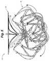
- FIG. 5is a side view of an embodiment of the LAA occlusion device shown in FIG. 1 depicting the degree of potential articulation between the cap and the bulb via the connection joint.
- FIG. 6is a close-up side view of the connection joint shown in FIG. 5 .
- FIG. 7is a sectional view of the connection joint shown in FIG. 6 .
- FIG. 8is a close-up view of the embodiment shown in FIG. 5 with the connection joint shown in section to illustrate its ability to provide and limit articulation between the cap and bulb.
- FIG. 9is an alternative close-up view of the embodiment shown in FIG. 5 with the connection joint shown in section to illustrate its ability to provide and limit articulation between the cap and bulb.
- FIG. 10is a side view of the device shown in FIG. 5 deployed within a left atrial appendage having a curved shape.
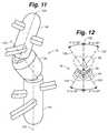
- FIG. 11is a detailed perspective view of the joint assembly illustrating its three potential axes of rotation and articulation.
- FIG. 12is a top down perspective view of the joint assembly shown in FIG. 11 depicting the potential full range of motion of the joint assembly components.
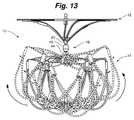
- FIG. 13is a side view of an alternative embodiment of the LAA occlusion device shown in FIG. 5 .
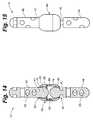
- FIG. 14is a close-up side view of the connection joint assembly shown in FIG. 10 .
- FIG. 15is a sectional view of the connection joint assembly shown in FIG. 11 .
- FIG. 16is a side view of an embodiment of the LAA device being deployed from a catheter and into the LAA.
- FIG. 17is a side view of the embodiment shown in FIG. 16 , wherein the device is shown deployed with the bulb fully within the LAA and the cap extending fully across the ostium.
- FIG. 1shows the LAA device 10 shown in its fully expanded configuration.
- the deviceincludes a cap structure 12 and a cage or bulb structure 14 .
- a connection joint assembly 16provides a pivoting and rotatable joint between the cap 12 and bulb 14 .
- FIG. 2shows the device 10 deployed within its intended environment of use within the left atrial appendage (LAA) 100 .
- LAAleft atrial appendage
- the cap structure 12When properly deployed the cap structure 12 over-lies the annular ostium 102 of the LAA 100 with the larger perimeter of the cap engaging or being positioned immediately adjacent to the surrounding atrial tissue 104 .
- the bulb structure 14when properly deployed, engages the walls 106 of the LAA without distortion or application of force sufficient to distend or alter the shape of the LAA.
- the connection joint assembly 16allow the cap 12 and bulb 14 to be moved and deployed effectively independent of one another, thus allowing the cap 12 to have a secure engagement across the ostium 102 and the bulb 14 to be firmly positioned within the LAA 100 regardless of the shape, or tortuosity of the anatomy.
- the cap 12is comprised of a plurality of proximal wire supports or loops 20 that extend from the base layer 32 of the sail or ostial cover 30 .
- Each proximal wire loop 20may be comprised of a single wire 22 (which may be a stranded wire of multiple wire filaments with a larger core filament surrounded by up to 12 smaller diameter filaments) of a shape memory material such as Nitinol.
- connection member 42extends from the proximal post 40 of the joint assembly 16 (discussed in greater detail below) to a connection member 42 , whereupon the wire 22 loops back to the post 40 to complete the structure of the wire loop 20 .
- Each connection member 42includes a plurality of through holes 43 (best seen in FIG. 4 ) through with a bio-compatible filament or braid (not shown) may be threaded to secure the cover 30 to each wire loop 22 .
- the cover 30is a representative multilayer structure having a base layer 32 and secondary or “petal” layer 34 and a top layer 36 .
- Base layer 32 and petal layer 34are comprised of mesh of any of a variety of bio-compatible materials such as: polyethylene terephthalate, polyester (DACRONTM), Polyvinyl Alcohol (PVA), polyurethane, etc.
- Layers 32 and 34may have same of different porosity and may be woven or manufactured with different thicknesses or other characteristics.
- the base layer 32may be a single unitary piece of mesh material, or as in the embodiment shown in FIG. 4 , comprised of two hemi-spheres 31 and 33 of material joined together along a common border 35 by sutures or other retaining mechanism.
- the base layeris comprised of multiple joined sections of material of any number desired. The junction of the sections 31 and 33 of the base layer may be achieved by suturing or other engagement mechanism, or by simply allowing the portions to abut or overlap one another at or along the border 35 .
- the secondary layer 34here multiple sections or petals 38 of ovoid or elliptical shaped material are arranged in a continuous and overlapping manner with a front edge 37 of a given petal 38 positioned either under or over the back edge 39 of the immediately adjacent petal 38 .
- the overlapping arrangement of petals 38As with the border(s) 35 of the base layer 32 , the overlapping arrangement of petals 38 .
- the top or securement layer 36 of materialis a layer of substantially solid or tightly woven or extruded mesh material having greater strength than the under lying layers 32 and 34 .
- the securement layer's primary functionis to act as a buffer and securement surface for securing the cover 30 , as a whole, to an engagement hub 50 .
- Each layer 32 , 34 add 36defines a central opening or hole 52 a , 52 , b and 52 c (respectively). Through which a portion (or shaft) of the engagement hub 50 passes so as to cinch the layers of the cover 30 together and hold them in place adjacent one another; while simultaneously ensuring that the cover 30 has sufficient strength to resist tearing or disruption during the crimping and/or delivery process discussed in greater detail below.
- the bulb structure 14is made up of a collection of distal wire loops 60 .
- the distal wire loops 60comprise a single wire or wire braid 22 that passes through the distal post 44 of the joint assembly 16 and extend to the terminal post 70 ; with the ends of the wire 22 of each distal loop 60 collected in a crimp coupler 62 .
- a companion collar 64connects the wire 22 of adjacent distal wire loops 60 , to provide structural stability and support to the bulb structure 14 .
- the collars 64connect immediately adjacent wire loops and permit forces to be shared by the two loops while not influencing other wire loops of the bulb structure 14 .
- the collars 64also include barbs 66 , which extend distally from each coupler 64 .
- the barbs 66are sized and arranged such that when the bulb 14 is deployed into the LAA 100 , such in the manner shown in FIG. 2 , the barbs 66 engage the walls 106 of the LAA, thereby ensuring that the bulb 14 maintains its secure position within the LAA space indefinitely once fully deployed therein.
- the collars 64provide the bulb structure 14 with support and structural stability, it must be noted that the arrangement of wire loops 60 is such that when the bulb 14 is fully deployed within the space of the LAA 100 , the bulb will minimally (if at all) distort, distend or otherwise affect the size or shape of the LAA.
- the joint assembly 16comprises the aforementioned proximal post 40 to which the wire loops 20 of the cap structure 12 are threaded and engaged; a distal post 44 to which the wires 22 of wire loops 60 of the bulb structure 14 are threaded and engaged.
- An end of each post 40 and 44are held movable adjacent one another within a joint housing 46 . Openings 55 of the posts 40 and 44 , through which the wires 22 of the respective structures 12 and 14 are engaged are depicted in FIGS. 6-7 .
- the particular arrangement of the post 40 and 44 ends within the joint housing 46 and the unique structure of the housing 46provides the device 10 with the a fluid connection between the cap structure 12 and bulb structure 14 , allowing the bulb structure 14 to be rotationally and pivotally articulated relative to the cap structure 12 to a degree limited only by the interference presented by the aforementioned structures themselves, or by the limitations provided by the joint assembly 16 , such as in the manner described below.
- proximal post 40includes a proximal neck 41 that terminates at a first or Wdrasler@comcast.netfirst ball joint 70 and distal post 44 includes a distal neck 45 that terminates at a second or second ball joint 74 .
- the ball jointsare not complete “balls” but merely the rounded aspect of the joint assembly. Their specific shape and dimensions may vary and the particular manner in which they engage with or extend from their respective necks ( 41 / 45 ) may likewise be varied.
- the ball jointsare ellipsoid or oval in shape. In at least one embodiment they are substantially spherical in shape above the interface with the neck. In at least one embodiment the ball joints have a flattened or “bone shaped” end.
- a hard metalsuch as titanium or other similar material suitable for use in medical implantation, is used to construct the parts of the joint assembly 16 including the housing 46 , shafts 40 and 44 , etc.
- the first ball joint 70is contained within a first sleeve 80 of the joint housing 46 and the second ball joint 74 is contained within a second sleeve 84 of the joint housing 46 , such that each sleeve 80 / 84 of the housing 46 forms the “socket” for moveably retaining the “ball” of the respective ball joint 70 / 74 in proximal and distal “ball and socket” type connections.
- Second sleeve 84includes a cuff or collar 86 which supports a washer 88 and biases the washer 88 between the first sleeve 80 and second sleeve 84 .
- Each sleevehas a sleeve opening 90 .
- the sleeve openings 90if larger in diameter than the diameter of the proximal neck 41 or distal neck 45 which passes through a respective opening 90 , but narrower in diameter than the diameter of the first ball joint 70 or second ball joint 74 thereby retaining the ball joints 70 and 74 within the interior 92 of the joint housing 46 .
- the sleeves 80 and 84 which comprise the joint housing 46are mechanically secured to one another, or may be chemically or heat welded or together.
- the aforementioned componentsresult in a joint assembly 16 wherein two ball joints 70 and 74 are able to rotate and pivot independently of each other relative to the housing 46 .
- the ball joints 70 and 74are separated by the washer 88 so that they do not come in contact with each other and restrict each other's movement.
- the washer 150also prevents the ball joints 70 and 74 from moving too far into the center of the sleeves 80 and 84 .
- the diameter of the openings 90 relative to the diameter of the necks 41 and 45likewise acts as a limit on the degree of motion that the shafts 40 and 44 are able to demonstrate relative to the housing 46 . This is perhaps best shown in FIGS. 8-9 wherein the extreme limits of the pivotal movement of shafts 40 and 44 are illustrated by the interaction of the opening 90 with the necks 41 and 45 .
- the shafts 40 and 44may be provided with an extreme amount of motion, thereby allowing the cap 12 and bulb 14 a corresponding amount of articulation relative to the joint assembly 16 and to one another as illustrated in FIG. 5 .
- this high degree of articulationallows the device 10 to be successfully deployed into left atrial appendages having even the most tortuous of shapes.
- the device 10is deployed within an LAA 100 whose walls 106 define a sock-like shape having a substantially angled curve or bend 108 .
- the bend 108may define an angle 110 of up to about 70 degrees relative to the longitudinal axis 112 , as defined by the walls 106 , which define the initial LAA opening (ostium 102 ). Because of the high degree of articulation provided by the joint assembly 16 , the present device may be deployed in even the most curvaceous of left atrial appendages without undue strain on the surrounding anatomy.
- the high degree of flexibility that the joint assembly 16 exhibitsprovides the device 10 not only with the ability to be deployed around a bend but to deploy around a bend in three dimensions such as in the manner illustrated in FIGS. 11-12 .
- the joint assembly 16is shown relative to three axes of articulation and rotation 120 , 124 and 126 .
- Proximal post 40extends along the proximal axis of rotation 120 ;
- distal post 44extend along the distal axis of rotation 124 .
- Each post 40 and 44(by way of the first ball joint 70 and the second ball joint 74 as previously discussed) are separately articulable in any direction relative to the housing axis of rotation 126 which corresponds to and extends along the length of the joint assembly housing 46 .
- each post 40 and 44and by extension the cap 12 and bulb 14 respectively engaged thereto (not shown, see FIG. 10 )—may be positioned and form an angle with the housing 46 that is different from one another and in any direction.
- the cap 12 and bulb 14 componentsmay each be positioned in such a manner as to form angles along their respective axis of rotation, in any direction, relative to the housing 46 of the joint assembly 16 of between 0 to approximately 35 degrees respectively.
- a device 10 having such extreme flexibilityis not ideal however in all cases.
- an unrestricted degree of rotational and pivotal movementmay in some cases make the implantation of the device 10 into an LAA more difficult.
- It has been found through laboratory experimentation that too much articulation on the bulb side (distal) of the joint assembly 16may in some cases cause complications in properly delivering the device.
- potential articulation of the shafts 40 and 44 relative to the housing 46have been limited by modifying the diameter of the opening 90 of sleeve 80 and/or by making the neck 41 of post 40 larger relative to the opening 90 of the sleeve 80 so as to limit the potential motion between the post 40 and housing 46 .
- opening and neck diametersmay be provided instead, or in addition to, that described above to the distal neck 45 and sleeve 84 , so as to limit the motion between the housing 46 and distal post 44 .
- Any of a variety of relative diameters between the necks 41 and 45 versus the openings 90may be provided to the device 10 as may be desired.
- the unique features of the device 10are made clear. Some of these features include providing a highly variable articulable joint assembly that allows for a wide degree of freedom of movement between the ostial cap and the bulb structure of the device. This allows the device to be oriented in any manner desired and to be adaptable to any LAA location or configuration.
- the bulb structureis configured such that when fully deployed within the LAA the bulb does not impact the shape of the LAA space.
- the device 10When delivering the device 10 to the LAA 100 of a patient via catheter 200 such as in the manner shown in FIG. 16 , the device 10 is folded or collapsed into a confined state such that the diameter of the device 10 is sufficient to allow the device to be loaded into the interior of a delivery catheter 200 .
- the delivery catheter 200is advanced in to the left atrium and the delivery tip 202 of the catheter is inserted about 10 mm-20 mm past the ostium 102 of the LAA 100 .
- the device 10is then advanced out of the catheter (or a delivery sheath his pulled back from the device, etc.) and the bulb structure 14 is advanced into the LAA space where the distal wire loops 60 self-expand to the deployed diameter.
- the deployed diameterbeing greater than the confined diameter.
- the device 10is shown in FIG. 17 such that even when allowed to fully deploy within the confines of a tortious ostium 102 , the bulb structure 14 minimally strains the surrounding tissue 104 .
- Cap structure 30includes several features to allow and encourage tissue growth therethrough to ensure eventual and compete occlusion of the LAA in the manner desired.
Landscapes
- Health & Medical Sciences (AREA)
- Life Sciences & Earth Sciences (AREA)
- Surgery (AREA)
- Veterinary Medicine (AREA)
- Animal Behavior & Ethology (AREA)
- Public Health (AREA)
- General Health & Medical Sciences (AREA)
- Engineering & Computer Science (AREA)
- Biomedical Technology (AREA)
- Heart & Thoracic Surgery (AREA)
- Medical Informatics (AREA)
- Molecular Biology (AREA)
- Nuclear Medicine, Radiotherapy & Molecular Imaging (AREA)
- Reproductive Health (AREA)
- Vascular Medicine (AREA)
- Cardiology (AREA)
- Anesthesiology (AREA)
- Hematology (AREA)
- Surgical Instruments (AREA)
- Prostheses (AREA)
Abstract
Description
Claims (10)
Priority Applications (2)
| Application Number | Priority Date | Filing Date | Title |
|---|---|---|---|
| US15/625,375US10441258B2 (en) | 2017-06-16 | 2017-06-16 | Uncoupled LAA device |
| US16/599,442US11284871B2 (en) | 2017-06-16 | 2019-10-11 | Uncoupled LAA device |
Applications Claiming Priority (1)
| Application Number | Priority Date | Filing Date | Title |
|---|---|---|---|
| US15/625,375US10441258B2 (en) | 2017-06-16 | 2017-06-16 | Uncoupled LAA device |
Related Child Applications (1)
| Application Number | Title | Priority Date | Filing Date |
|---|---|---|---|
| US16/599,442ContinuationUS11284871B2 (en) | 2017-06-16 | 2019-10-11 | Uncoupled LAA device |
Publications (2)
| Publication Number | Publication Date |
|---|---|
| US20180360432A1 US20180360432A1 (en) | 2018-12-20 |
| US10441258B2true US10441258B2 (en) | 2019-10-15 |
Family
ID=64656014
Family Applications (2)
| Application Number | Title | Priority Date | Filing Date |
|---|---|---|---|
| US15/625,375Active2038-03-30US10441258B2 (en) | 2017-06-16 | 2017-06-16 | Uncoupled LAA device |
| US16/599,442Active2038-06-25US11284871B2 (en) | 2017-06-16 | 2019-10-11 | Uncoupled LAA device |
Family Applications After (1)
| Application Number | Title | Priority Date | Filing Date |
|---|---|---|---|
| US16/599,442Active2038-06-25US11284871B2 (en) | 2017-06-16 | 2019-10-11 | Uncoupled LAA device |
Country Status (1)
| Country | Link |
|---|---|
| US (2) | US10441258B2 (en) |
Cited By (3)
| Publication number | Priority date | Publication date | Assignee | Title |
|---|---|---|---|---|
| US10758241B1 (en) | 2019-03-25 | 2020-09-01 | Laminar, Inc. | Devices, systems, and methods for treating the left atrial appendage |
| WO2022271792A3 (en)* | 2021-06-22 | 2023-03-02 | Ventrimend, Inc. | Systems and methods for treating the left atrial appendage |
| US12303116B2 (en) | 2020-03-24 | 2025-05-20 | Laminar, Inc. | Devices, systems, and methods for occluding cavities within the body |
Families Citing this family (16)
| Publication number | Priority date | Publication date | Assignee | Title |
|---|---|---|---|---|
| JP6423851B2 (en) | 2013-03-13 | 2018-11-14 | アーロン・ヴィ・カプラン | Device for emptying the left atrial appendage |
| US11399842B2 (en) | 2013-03-13 | 2022-08-02 | Conformal Medical, Inc. | Devices and methods for excluding the left atrial appendage |
| AU2015249283B2 (en) | 2014-04-25 | 2019-07-18 | Flow Medtech, Llc | Left atrial appendage occlusion device |
| CA2999169A1 (en) | 2014-09-19 | 2016-03-24 | Flow Medtech, Inc. | Left atrial appendage occlusion device delivery system |
| WO2018081466A2 (en) | 2016-10-27 | 2018-05-03 | Conformal Medical, Inc. | Devices and methods for excluding the left atrial appendage |
| US11426172B2 (en) | 2016-10-27 | 2022-08-30 | Conformal Medical, Inc. | Devices and methods for excluding the left atrial appendage |
| US11564693B2 (en)* | 2018-05-08 | 2023-01-31 | W. L. Gore & Associates, Inc. | Occluder devices |
| US12268394B2 (en) | 2019-02-08 | 2025-04-08 | Conformal Medical, Inc. | Devices and methods for excluding the left atrial appendage |
| US12144508B2 (en) | 2019-02-08 | 2024-11-19 | Conformal Medical, Inc. | Devices and methods for excluding the left atrial appendage |
| EP4563099A3 (en)* | 2019-08-30 | 2025-08-06 | Boston Scientific Scimed, Inc. | Left atrial appendage implant with sealing disk |
| US11534175B2 (en)* | 2020-01-28 | 2022-12-27 | Medtronic, Inc. | Modular left atrial appendage closure |
| JP2023533989A (en)* | 2020-07-07 | 2023-08-07 | ラミナー インコーポレイテッド | Devices, systems and methods for treating the left atrial appendage |
| CN112022246B (en)* | 2020-11-06 | 2021-02-26 | 上海介入医疗器械有限公司 | Left auricle occluder and use method thereof |
| CN113520486A (en)* | 2021-06-24 | 2021-10-22 | 珠海市人民医院 | Adjustable plugging device |
| CN113974716B (en)* | 2021-12-28 | 2022-06-21 | 先健科技(深圳)有限公司 | Blocking device |
| CN120227097A (en)* | 2023-12-29 | 2025-07-01 | 先健科技(深圳)有限公司 | Blocking device |
Citations (16)
| Publication number | Priority date | Publication date | Assignee | Title |
|---|---|---|---|---|
| US20050038470A1 (en)* | 2003-08-15 | 2005-02-17 | Van Der Burg Erik J. | System and method for delivering a left atrial appendage containment device |
| US20050273135A1 (en)* | 2004-05-07 | 2005-12-08 | Nmt Medical, Inc. | Catching mechanisms for tubular septal occluder |
| US20050277982A1 (en)* | 2003-01-22 | 2005-12-15 | Cardia, Inc. | Articulated center post |
| US20060241687A1 (en)* | 2005-03-16 | 2006-10-26 | Glaser Erik N | Septal occluder with pivot arms and articulating joints |
| US20070010851A1 (en)* | 2003-07-14 | 2007-01-11 | Chanduszko Andrzej J | Tubular patent foramen ovale (PFO) closure device with catch system |
| US20070244518A1 (en)* | 2003-07-14 | 2007-10-18 | Nmt Medical, Inc. | Patent foramen ovale (PFO) closure device with linearly elongating petals |
| US20080086168A1 (en)* | 2006-09-28 | 2008-04-10 | Ryan Cahill | Implant-catheter attachment mechanism using snare and method of use |
| US20090292310A1 (en)* | 2007-09-13 | 2009-11-26 | Dara Chin | Medical device for occluding a heart defect and a method of manufacturing the same |
| US7938826B2 (en)* | 2006-05-30 | 2011-05-10 | Coherex Medical, Inc. | Methods, systems, and devices for closing a patent foramen ovale using mechanical structures |
| US20120172927A1 (en)* | 2010-11-12 | 2012-07-05 | Campbell Benjamin D | Left atrial appendage occlusive devices |
| US20130218193A1 (en)* | 2012-02-21 | 2013-08-22 | Cardia, Inc. | Redeployable left atrial appendage occlusion device |
| US20130218192A1 (en)* | 2012-02-21 | 2013-08-22 | Gary S. Erzberger | Left atrial appendage occlusion device |
| US20140142610A1 (en)* | 2012-11-16 | 2014-05-22 | W.L. Gore & Associates, Inc. | Space Filling Devices |
| US8764848B2 (en)* | 2004-09-24 | 2014-07-01 | W.L. Gore & Associates, Inc. | Occluder device double securement system for delivery/recovery of such occluder device |
| US20150005810A1 (en)* | 2013-06-26 | 2015-01-01 | W. L. Gore & Associates, Inc. | Space filling devices |
| US20170258475A1 (en)* | 2014-09-12 | 2017-09-14 | Carag Ag | Occluder |
Family Cites Families (48)
| Publication number | Priority date | Publication date | Assignee | Title |
|---|---|---|---|---|
| US3874388A (en) | 1973-02-12 | 1975-04-01 | Ochsner Med Found Alton | Shunt defect closure system |
| US4007743A (en) | 1975-10-20 | 1977-02-15 | American Hospital Supply Corporation | Opening mechanism for umbrella-like intravascular shunt defect closure device |
| US4284166A (en) | 1979-04-13 | 1981-08-18 | Gale George A | Port devices for bass-reflex speaker enclosures |
| US4917089A (en) | 1988-08-29 | 1990-04-17 | Sideris Eleftherios B | Buttoned device for the transvenous occlusion of intracardiac defects |
| ATE107150T1 (en) | 1990-04-02 | 1994-07-15 | Kanji Inoue | DEVICE FOR CLOSING A SHUTTLE OPENING BY A NON-OPERATIONAL METHOD. |
| US5092424A (en) | 1990-12-03 | 1992-03-03 | Bose Corporation | Electroacoustical transducing with at least three cascaded subchambers |
| US5108420A (en) | 1991-02-01 | 1992-04-28 | Temple University | Aperture occlusion device |
| EP0545091B1 (en) | 1991-11-05 | 1999-07-07 | The Children's Medical Center Corporation | Occluder for repair of cardiac and vascular defects |
| EP0541063B1 (en) | 1991-11-05 | 1998-09-02 | The Children's Medical Center Corporation | Improved occluder for repair of cardiac and vascular defects |
| DK168419B1 (en) | 1991-11-25 | 1994-03-28 | Cook Inc A Cook Group Company | Abdominal wall support device and apparatus for insertion thereof |
| CA2128338C (en) | 1992-01-21 | 2004-10-12 | Gladwin S. Das | Septal defect closure device |
| US5626599A (en) | 1992-01-22 | 1997-05-06 | C. R. Bard | Method for the percutaneous transluminal front-end loading delivery of a prosthetic occluder |
| US5334137A (en) | 1992-02-21 | 1994-08-02 | Eagle Vision, Inc. | Lacrimal fluid control device |
| GB2269321B (en) | 1992-08-05 | 1996-06-26 | Nat Heart & Lung Inst | Implantable occluder devices for medical use |
| US5382260A (en) | 1992-10-30 | 1995-01-17 | Interventional Therapeutics Corp. | Embolization device and apparatus including an introducer cartridge and method for delivering the same |
| US5284488A (en) | 1992-12-23 | 1994-02-08 | Sideris Eleftherios B | Adjustable devices for the occlusion of cardiac defects |
| US5725552A (en) | 1994-07-08 | 1998-03-10 | Aga Medical Corporation | Percutaneous catheter directed intravascular occlusion devices |
| US5433727A (en) | 1994-08-16 | 1995-07-18 | Sideris; Eleftherios B. | Centering buttoned device for the occlusion of large defects for occluding |
| US6171329B1 (en) | 1994-12-19 | 2001-01-09 | Gore Enterprise Holdings, Inc. | Self-expanding defect closure device and method of making and using |
| US5702421A (en) | 1995-01-11 | 1997-12-30 | Schneidt; Bernhard | Closure device for closing a vascular opening, such as patent ductus arteriosus |
| US5634936A (en) | 1995-02-06 | 1997-06-03 | Scimed Life Systems, Inc. | Device for closing a septal defect |
| WO1997016119A1 (en) | 1995-10-30 | 1997-05-09 | Children's Medical Center Corporation | Self-centering umbrella-type septal closure device |
| DE19604817C2 (en) | 1996-02-09 | 2003-06-12 | Pfm Prod Fuer Die Med Ag | Device for closing defect openings in the human or animal body |
| US5920633A (en) | 1996-02-12 | 1999-07-06 | Yang; Yi-Fu | Thin-wall multi-concentric cylinder speaker enclosure with audio amplifier tunable to listening room |
| US5853422A (en) | 1996-03-22 | 1998-12-29 | Scimed Life Systems, Inc. | Apparatus and method for closing a septal defect |
| EP0900051A1 (en) | 1996-05-08 | 1999-03-10 | Salviac Limited | An occluder device |
| US5741297A (en) | 1996-08-28 | 1998-04-21 | Simon; Morris | Daisy occluder and method for septal defect repair |
| US6174322B1 (en) | 1997-08-08 | 2001-01-16 | Cardia, Inc. | Occlusion device for the closure of a physical anomaly such as a vascular aperture or an aperture in a septum |
| US6136015A (en) | 1998-08-25 | 2000-10-24 | Micrus Corporation | Vasoocclusive coil |
| US7044134B2 (en) | 1999-11-08 | 2006-05-16 | Ev3 Sunnyvale, Inc | Method of implanting a device in the left atrial appendage |
| US6389146B1 (en) | 2000-02-17 | 2002-05-14 | American Technology Corporation | Acoustically asymmetric bandpass loudspeaker with multiple acoustic filters |
| US6206907B1 (en) | 1999-05-07 | 2001-03-27 | Cardia, Inc. | Occlusion device with stranded wire support arms |
| US6379368B1 (en) | 1999-05-13 | 2002-04-30 | Cardia, Inc. | Occlusion device with non-thrombogenic properties |
| US6712836B1 (en) | 1999-05-13 | 2004-03-30 | St. Jude Medical Atg, Inc. | Apparatus and methods for closing septal defects and occluding blood flow |
| US6689150B1 (en) | 1999-10-27 | 2004-02-10 | Atritech, Inc. | Filter apparatus for ostium of left atrial appendage |
| DE10000137A1 (en) | 2000-01-04 | 2001-07-12 | Pfm Prod Fuer Die Med Ag | Implantate for closing defect apertures in human or animal bodies, bearing structure of which can be reversed from secondary to primary form by elastic force |
| US6551344B2 (en) | 2000-04-26 | 2003-04-22 | Ev3 Inc. | Septal defect occluder |
| US6511496B1 (en) | 2000-09-12 | 2003-01-28 | Advanced Cardiovascular Systems, Inc. | Embolic protection device for use in interventional procedures |
| EP2481356B1 (en) | 2003-07-14 | 2013-09-11 | W.L. Gore & Associates, Inc. | Tubular patent foramen ovale (PFO) closure device with catch system |
| US7144410B2 (en) | 2003-09-18 | 2006-12-05 | Cardia Inc. | ASD closure device with self centering arm network |
| US7905901B2 (en) | 2004-11-29 | 2011-03-15 | Cardia, Inc. | Self-centering occlusion device |
| US7582104B2 (en) | 2004-12-08 | 2009-09-01 | Cardia, Inc. | Daisy design for occlusion device |
| US9220487B2 (en) | 2006-08-09 | 2015-12-29 | Coherex Medical, Inc. | Devices for reducing the size of an internal tissue opening |
| US8366741B2 (en) | 2007-09-13 | 2013-02-05 | Cardia, Inc. | Occlusion device with centering arm |
| US9414842B2 (en) | 2007-10-12 | 2016-08-16 | St. Jude Medical, Cardiology Division, Inc. | Multi-component vascular device |
| US20090171386A1 (en) | 2007-12-28 | 2009-07-02 | Aga Medical Corporation | Percutaneous catheter directed intravascular occlusion devices |
| US20110082495A1 (en) | 2009-10-02 | 2011-04-07 | Ruiz Carlos E | Apparatus And Methods For Excluding The Left Atrial Appendage |
| CN103249374B (en) | 2010-07-02 | 2015-08-05 | Pfm医疗股份公司 | Left atrial appendage closure device |
- 2017
- 2017-06-16USUS15/625,375patent/US10441258B2/enactiveActive
- 2019
- 2019-10-11USUS16/599,442patent/US11284871B2/enactiveActive
Patent Citations (23)
| Publication number | Priority date | Publication date | Assignee | Title |
|---|---|---|---|---|
| US20050277982A1 (en)* | 2003-01-22 | 2005-12-15 | Cardia, Inc. | Articulated center post |
| US9861346B2 (en)* | 2003-07-14 | 2018-01-09 | W. L. Gore & Associates, Inc. | Patent foramen ovale (PFO) closure device with linearly elongating petals |
| US8480706B2 (en)* | 2003-07-14 | 2013-07-09 | W.L. Gore & Associates, Inc. | Tubular patent foramen ovale (PFO) closure device with catch system |
| US20070010851A1 (en)* | 2003-07-14 | 2007-01-11 | Chanduszko Andrzej J | Tubular patent foramen ovale (PFO) closure device with catch system |
| US20070244518A1 (en)* | 2003-07-14 | 2007-10-18 | Nmt Medical, Inc. | Patent foramen ovale (PFO) closure device with linearly elongating petals |
| US20050038470A1 (en)* | 2003-08-15 | 2005-02-17 | Van Der Burg Erik J. | System and method for delivering a left atrial appendage containment device |
| US8257389B2 (en)* | 2004-05-07 | 2012-09-04 | W.L. Gore & Associates, Inc. | Catching mechanisms for tubular septal occluder |
| US20120316602A1 (en)* | 2004-05-07 | 2012-12-13 | W.L. Gore & Associates, Inc. | Catching Mechanisms for Tubular Septal Occluder |
| US8480709B2 (en)* | 2004-05-07 | 2013-07-09 | W.L. Gore & Associates, Inc. | Catching mechanisms for tubular septal occluder |
| US20050273135A1 (en)* | 2004-05-07 | 2005-12-08 | Nmt Medical, Inc. | Catching mechanisms for tubular septal occluder |
| US20130289618A1 (en)* | 2004-05-07 | 2013-10-31 | W.L. Gore & Associates, Inc. | Catching Mechanisms for Tubular Septal Occluder |
| US8764848B2 (en)* | 2004-09-24 | 2014-07-01 | W.L. Gore & Associates, Inc. | Occluder device double securement system for delivery/recovery of such occluder device |
| US20060241687A1 (en)* | 2005-03-16 | 2006-10-26 | Glaser Erik N | Septal occluder with pivot arms and articulating joints |
| US7938826B2 (en)* | 2006-05-30 | 2011-05-10 | Coherex Medical, Inc. | Methods, systems, and devices for closing a patent foramen ovale using mechanical structures |
| US20080086168A1 (en)* | 2006-09-28 | 2008-04-10 | Ryan Cahill | Implant-catheter attachment mechanism using snare and method of use |
| US20090292310A1 (en)* | 2007-09-13 | 2009-11-26 | Dara Chin | Medical device for occluding a heart defect and a method of manufacturing the same |
| US20120172927A1 (en)* | 2010-11-12 | 2012-07-05 | Campbell Benjamin D | Left atrial appendage occlusive devices |
| US20130218192A1 (en)* | 2012-02-21 | 2013-08-22 | Gary S. Erzberger | Left atrial appendage occlusion device |
| US9554804B2 (en)* | 2012-02-21 | 2017-01-31 | Cardia, Inc. | Redeployable left atrial appendage occlusion device |
| US20130218193A1 (en)* | 2012-02-21 | 2013-08-22 | Cardia, Inc. | Redeployable left atrial appendage occlusion device |
| US20140142610A1 (en)* | 2012-11-16 | 2014-05-22 | W.L. Gore & Associates, Inc. | Space Filling Devices |
| US20150005810A1 (en)* | 2013-06-26 | 2015-01-01 | W. L. Gore & Associates, Inc. | Space filling devices |
| US20170258475A1 (en)* | 2014-09-12 | 2017-09-14 | Carag Ag | Occluder |
Cited By (6)
| Publication number | Priority date | Publication date | Assignee | Title |
|---|---|---|---|---|
| US10758241B1 (en) | 2019-03-25 | 2020-09-01 | Laminar, Inc. | Devices, systems, and methods for treating the left atrial appendage |
| US11123080B2 (en) | 2019-03-25 | 2021-09-21 | Laminar, Inc. | Devices, systems, and methods for treating the left atrial appendage |
| US11219462B2 (en) | 2019-03-25 | 2022-01-11 | Laminar, Inc. | Devices, systems, and methods for treating the left atrial appendage |
| US11399843B2 (en) | 2019-03-25 | 2022-08-02 | Laminar, Inc. | Devices, systems, and methods for treating the left atrial appendage |
| US12303116B2 (en) | 2020-03-24 | 2025-05-20 | Laminar, Inc. | Devices, systems, and methods for occluding cavities within the body |
| WO2022271792A3 (en)* | 2021-06-22 | 2023-03-02 | Ventrimend, Inc. | Systems and methods for treating the left atrial appendage |
Also Published As
| Publication number | Publication date |
|---|---|
| US11284871B2 (en) | 2022-03-29 |
| US20180360432A1 (en) | 2018-12-20 |
| US20200038004A1 (en) | 2020-02-06 |
Similar Documents
| Publication | Publication Date | Title |
|---|---|---|
| US11284871B2 (en) | Uncoupled LAA device | |
| US20250099244A1 (en) | System And Method For Cardiac Valve Repair And Replacement | |
| JP6761120B2 (en) | Valve fastener | |
| US11648108B2 (en) | Heart valve prosthesis | |
| EP3960097B1 (en) | Occluder support and preparation method therefor | |
| US8500622B2 (en) | Ventricular function assisting device and a method and apparatus for implanting it | |
| ES2639828T3 (en) | Medical occlusion device | |
| JP6423787B2 (en) | Devices, systems, and methods for transcatheter treatment of valvular reflux | |
| JP6018064B2 (en) | System and method for rapid placement of a surgical heart valve | |
| EP4159162B1 (en) | Repair device for treating tricuspid regurgitation | |
| JP2020531178A (en) | Artificial heart valve with tethered joint | |
| JP7732625B2 (en) | Medical devices and systems for closing tissue openings and methods thereof | |
| WO2017016411A1 (en) | Left auricle occluding device | |
| JP2003505146A (en) | Heart valve prosthesis having an elastically deformable retention member | |
| CN113286550B (en) | Occluder insertion system | |
| US20220104830A1 (en) | Occlusion means, system comprising an occlusion means and an insertion catheter, and method for producing the system | |
| JP2022516603A (en) | Stent graft and how to use it | |
| CN110934664A (en) | Heart valve | |
| CN216060638U (en) | occlusion device | |
| CN218220396U (en) | Mitral annulus contracting device | |
| US20250107807A1 (en) | Occluder support and preparation method therefor | |
| CN220695307U (en) | Plugging device | |
| CN221844845U (en) | A locking system for an implantable tension device | |
| WO2024093232A1 (en) | Stable-fitting valve clip device and valve clip system |
Legal Events
| Date | Code | Title | Description |
|---|---|---|---|
| AS | Assignment | Owner name:CARDIA, INC., MINNESOTA Free format text:ASSIGNMENT OF ASSIGNORS INTEREST;ASSIGNORS:CORCORAN, MICHAEL PATRICK;MARINO, JOSEPH A.;TANG, ENGLONG;REEL/FRAME:043488/0533 Effective date:20170901 | |
| STPP | Information on status: patent application and granting procedure in general | Free format text:DOCKETED NEW CASE - READY FOR EXAMINATION | |
| STPP | Information on status: patent application and granting procedure in general | Free format text:NON FINAL ACTION MAILED | |
| STPP | Information on status: patent application and granting procedure in general | Free format text:RESPONSE TO NON-FINAL OFFICE ACTION ENTERED AND FORWARDED TO EXAMINER | |
| STPP | Information on status: patent application and granting procedure in general | Free format text:PUBLICATIONS -- ISSUE FEE PAYMENT RECEIVED | |
| STCF | Information on status: patent grant | Free format text:PATENTED CASE | |
| AS | Assignment | Owner name:CARDIA, INC, MINNESOTA Free format text:CORRECTIVE ASSIGNMENT TO CORRECT THE IDENTIFICATION OF THE ASSIGNEE FROM INNOVAPPTIVE, INC. TO CARDIA, INC. PREVIOUSLY RECORDED ON REEL 043488 FRAME 0533. ASSIGNOR(S) HEREBY CONFIRMS THE ORIGINALLY LISTED ASSIGNEE, INNOVAPPTIVE, INC. WAS LISTED IN ERROR AND THAT CARDIA, INC. IS THE CORRECT ASSIGNEE;ASSIGNORS:CORCORAN, MICHAEL PATRICK;MARINO, JOSEPH A;TANG, ENLONG;REEL/FRAME:050711/0341 Effective date:20170901 | |
| AS | Assignment | Owner name:ATRIAL SOLUTIONS, INC., DELAWARE Free format text:ASSIGNMENT OF ASSIGNORS INTEREST;ASSIGNOR:CARDIA, INC.;REEL/FRAME:061376/0295 Effective date:20221011 | |
| MAFP | Maintenance fee payment | Free format text:PAYMENT OF MAINTENANCE FEE, 4TH YR, SMALL ENTITY (ORIGINAL EVENT CODE: M2551); ENTITY STATUS OF PATENT OWNER: SMALL ENTITY Year of fee payment:4 |