US10441155B2 - Medical devices with battery removal - Google Patents
Medical devices with battery removalDownload PDFInfo
- Publication number
- US10441155B2 US10441155B2US16/139,813US201816139813AUS10441155B2US 10441155 B2US10441155 B2US 10441155B2US 201816139813 AUS201816139813 AUS 201816139813AUS 10441155 B2US10441155 B2US 10441155B2
- Authority
- US
- United States
- Prior art keywords
- outer housing
- power source
- medical device
- opening
- holder
- Prior art date
- Legal status (The legal status is an assumption and is not a legal conclusion. Google has not performed a legal analysis and makes no representation as to the accuracy of the status listed.)
- Active
Links
Images


Classifications
- A—HUMAN NECESSITIES
- A61—MEDICAL OR VETERINARY SCIENCE; HYGIENE
- A61B—DIAGNOSIS; SURGERY; IDENTIFICATION
- A61B1/00—Instruments for performing medical examinations of the interior of cavities or tubes of the body by visual or photographical inspection, e.g. endoscopes; Illuminating arrangements therefor
- A61B1/32—Devices for opening or enlarging the visual field, e.g. of a tube of the body
- A—HUMAN NECESSITIES
- A61—MEDICAL OR VETERINARY SCIENCE; HYGIENE
- A61B—DIAGNOSIS; SURGERY; IDENTIFICATION
- A61B1/00—Instruments for performing medical examinations of the interior of cavities or tubes of the body by visual or photographical inspection, e.g. endoscopes; Illuminating arrangements therefor
- A61B1/00002—Operational features of endoscopes
- A61B1/00025—Operational features of endoscopes characterised by power management
- A61B1/00027—Operational features of endoscopes characterised by power management characterised by power supply
- A61B1/00032—Operational features of endoscopes characterised by power management characterised by power supply internally powered
- A—HUMAN NECESSITIES
- A61—MEDICAL OR VETERINARY SCIENCE; HYGIENE
- A61B—DIAGNOSIS; SURGERY; IDENTIFICATION
- A61B1/00—Instruments for performing medical examinations of the interior of cavities or tubes of the body by visual or photographical inspection, e.g. endoscopes; Illuminating arrangements therefor
- A61B1/00064—Constructional details of the endoscope body
- A61B1/00066—Proximal part of endoscope body, e.g. handles
- A—HUMAN NECESSITIES
- A61—MEDICAL OR VETERINARY SCIENCE; HYGIENE
- A61B—DIAGNOSIS; SURGERY; IDENTIFICATION
- A61B1/00—Instruments for performing medical examinations of the interior of cavities or tubes of the body by visual or photographical inspection, e.g. endoscopes; Illuminating arrangements therefor
- A61B1/00064—Constructional details of the endoscope body
- A61B1/00108—Constructional details of the endoscope body characterised by self-sufficient functionality for stand-alone use
- A—HUMAN NECESSITIES
- A61—MEDICAL OR VETERINARY SCIENCE; HYGIENE
- A61B—DIAGNOSIS; SURGERY; IDENTIFICATION
- A61B1/00—Instruments for performing medical examinations of the interior of cavities or tubes of the body by visual or photographical inspection, e.g. endoscopes; Illuminating arrangements therefor
- A61B1/06—Instruments for performing medical examinations of the interior of cavities or tubes of the body by visual or photographical inspection, e.g. endoscopes; Illuminating arrangements therefor with illuminating arrangements
- A61B1/0661—Endoscope light sources
- A61B1/0684—Endoscope light sources using light emitting diodes [LED]
- A—HUMAN NECESSITIES
- A61—MEDICAL OR VETERINARY SCIENCE; HYGIENE
- A61B—DIAGNOSIS; SURGERY; IDENTIFICATION
- A61B1/00—Instruments for performing medical examinations of the interior of cavities or tubes of the body by visual or photographical inspection, e.g. endoscopes; Illuminating arrangements therefor
- A61B1/267—Instruments for performing medical examinations of the interior of cavities or tubes of the body by visual or photographical inspection, e.g. endoscopes; Illuminating arrangements therefor for the respiratory tract, e.g. laryngoscopes, bronchoscopes
- A—HUMAN NECESSITIES
- A61—MEDICAL OR VETERINARY SCIENCE; HYGIENE
- A61B—DIAGNOSIS; SURGERY; IDENTIFICATION
- A61B1/00—Instruments for performing medical examinations of the interior of cavities or tubes of the body by visual or photographical inspection, e.g. endoscopes; Illuminating arrangements therefor
- A61B1/303—Instruments for performing medical examinations of the interior of cavities or tubes of the body by visual or photographical inspection, e.g. endoscopes; Illuminating arrangements therefor for the vagina, i.e. vaginoscopes
- A—HUMAN NECESSITIES
- A61—MEDICAL OR VETERINARY SCIENCE; HYGIENE
- A61B—DIAGNOSIS; SURGERY; IDENTIFICATION
- A61B1/00—Instruments for performing medical examinations of the interior of cavities or tubes of the body by visual or photographical inspection, e.g. endoscopes; Illuminating arrangements therefor
- A61B1/31—Instruments for performing medical examinations of the interior of cavities or tubes of the body by visual or photographical inspection, e.g. endoscopes; Illuminating arrangements therefor for the rectum, e.g. proctoscopes, sigmoidoscopes, colonoscopes
- A—HUMAN NECESSITIES
- A61—MEDICAL OR VETERINARY SCIENCE; HYGIENE
- A61B—DIAGNOSIS; SURGERY; IDENTIFICATION
- A61B17/00—Surgical instruments, devices or methods
- A61B17/02—Surgical instruments, devices or methods for holding wounds open, e.g. retractors; Tractors
- A—HUMAN NECESSITIES
- A61—MEDICAL OR VETERINARY SCIENCE; HYGIENE
- A61B—DIAGNOSIS; SURGERY; IDENTIFICATION
- A61B17/00—Surgical instruments, devices or methods
- A61B2017/00681—Aspects not otherwise provided for
- A61B2017/00734—Aspects not otherwise provided for battery operated
Definitions
- the present inventionrelates to medical devices used for examination of a patient or during surgery, including but not limited to speculums, retractors, larygoscopes, suction devices, anoscopes, cannula and other examination and surgical devices which may use batteries, such as electrocautery devices, scalpels, sigmoidoscopes, proctoscopes, and others.
- a speculumis a medical instrument used for dilating an opening of a body cavity for medical examinations.
- a two-blade speculumis commonly used in a gynecological examination.
- the pair of hinged blades of the speculumare configured in a “closed state” when introduced into a body cavity, for example, a patient's vagina, and the blades are articulated to an “opened state” to dilate, for example, the vaginal walls, allowing medical examiners to examine internal genital organs.
- a retractoris commonly used during a surgical procedure to separate the edges of a surgical incision or wound or to hold back tissues or organs to expose the area on which surgery is conducted.
- Varieties of other types of retractorssuch as laryngoscopes, nasal speculums, aural speculums, etc. are commonly used in other settings.
- the conventional speculums and retractorsare typically made of metals, designed to be reused subject to extensive sterilization for preventing cross contamination.
- the process of sterilizing reusable speculums and retractorsproved not only to be a great nuisance but also unnecessarily costly and time-consuming.
- the problemsexacerbate in settings such as emergency rooms, urgent care, etc. where immediate attention is desired.
- manufacturershave developed plastic speculums and retractors made from lightweight and inexpensive materials to eliminate the above noted problems.
- the plastic medical and surgical devicesare comparatively inexpensive and are wholly disposable after a single use.
- Some retractors and speculumsinclude illuminating means for illuminating the subject area for examination.
- the illuminating meansgenerally include a light source such as a small light bulb or an LED that is operatively coupled to an external power source or to a portable power source such as a battery via simple circuitry.
- the illuminating means used in conjunction with disposable speculums and retractorsare disposed together with the speculums and retractors.
- Other medical devicesuse a power source for powering other components of the medical device, not limited to an illumination assembly.
- a battery-powered medical deviceis an electrocautery device which uses a power source for heating an electrode.
- a battery-powered medical devicecomprising an outer housing having an opening formed therein, a power source housed within the outer housing, the outer housing being configured to at least partially enclose the power source so as to prevent contamination of the power source with biohazardous materials, the power source being removable from the outer housing via the opening, and a cover configured to cover the opening in the outer housing and to retain the power source within the outer housing, wherein the cover is configured to be operated by a user to expose the opening in the outer housing, when the cover is operated to expose the opening, the outer housing is configured to release the power source via the opening without requiring physical contact between the user and the power source, and when the cover is operated to expose the opening, the outer housing is configured to provide a direct path for release of the power source via the opening, such path providing no contact with contaminated surfaces of the medical device.
- the medical devicefurther comprises an actuator for releasing the power source from the outer housing via the opening without user contact with the power source.
- the actuatormay be a biasing member biasing the power source in a direction of the cover when the cover covers the opening in the outer housing, and/or a band disposed partially around the power source and configured to be pulled by the user to release the power source via the opening in the outer housing.
- the medical devicemay be a disposable single-use medical device and the removable power source comprises one or more non-rechargeable, single-use batteries.
- the outer housingmay be configured to prevent replacement of the power source after the power source is released therefrom.
- the outer housingcomprises a handle portion having a first end and a second end, the opening in the outer housing is formed in the first end, and the power source is housed in the handle portion at a position closer to the second end than to the first end.
- the outer housingis a handle portion of the medical device and the medical device further comprises an operative portion coupled to a proximal end of the handle portion.
- a distal end of the handle portionforms the opening in the outer housing, and the power source is biased against the cover covering the opening so that when the cover is operated to expose the opening, the removable power source is ejected from the handle portion.
- the medical devicemay further include a lock configured to retain the cover in a first position covering the opening and configured to be operated by the user to release the cover from the first position to a second position so as to expose the opening.
- the medical devicefurther comprises a compartment for partially enclosing the power source, with the compartment being at least partially enclosed by the handle portion and having an open side configured to communicate with the opening in the handle portion.
- the coveris engaged with one or more of the compartment and the outer housing.
- the medical deviceis one of a speculum, a retractor, an anoscope and a laryngoscope, and comprises an illumination assembly including at least one light source and the power source for powering the at least one light source.
- the outer housingcomprises a handle portion and at least one blade portion coupled to the handle portion, with the power source being housed in one of the handle portion and the blade portion.
- a battery-operated medical devicecomprising: an outer housing having an opening formed therein, a power source housed within the outer housing so as to prevent contamination of the power source with biohazardous materials, and a holder configured to be movable from a first position to a second position relative to the outer housing, the holder being further configured to partially enclose the power source and to hold the power source within the outer housing when the holder is in the first position, and further configured to release the power source from the outer housing via the opening when the holder is in the second position.
- the outer housing and the holderare structured to cause the power source to be released from the outer housing while the holder remains connected to the medical device.
- the holderis configured to be inhibited from being moved from the second position to the first position.
- the holder and the outer housingare configured to hold the power source between the holder and an inner wall of the outer housing, and when the holder is in the second position, the holder and the outer housing are configured to release the power source through a space between the holder and the inner wall of the outer housing.
- the inner wall of the outer housingmay include a projection configured to abut the power source held by the holder in the first position.
- the holdermay have a substantially C-shaped cross-section.
- the outer housingincludes a handle portion having a proximal end and a distal end, with the opening in the outer housing being formed in the distal end of the handle portion, and the holder is configured to hold the power source within the handle portion in the first position.
- the holdermay be configured to hold the power source in the handle portion at a position closer to the proximal end of the handle portion than to the distal end of the handle portion.
- the medical deviceincludes an operating member configured to be operated by a user to move the holder from the first position to the second position and wherein: the operating member is coupled to the holder and extends from the proximal end of the handle portion in the first position of the holder, and the operating member is configured to be pushed by the user into the proximal end of the handle portion so as to move the holder to the second position.
- the holdercomprises a compartment for partially enclosing the power source and has an open side configured to communicate with the opening in the outer housing when the compartment is in the second position.
- the compartmentis at least partially enclosed by the outer housing.
- the compartmentmay include a sidewall configured to cover the opening in the outer housing when the compartment is in the first position, and may be configured to pivot into the second position so that the open side of the compartment is in communication with the opening in the outer housing.
- the outer housingcomprises a handle portion, a blade portion and a curved portion connecting the handle portion to the blade portion, and the opening is formed in one of the handle portion, the blade portion and the curved portion.
- the medical devicemay be one of a retractor, a speculum, an anoscope and a laryngoscope, and the outer housing may comprise a handle portion and at least one blade portion extending from the handle portion.
- the medical devicemay comprise an illumination assembly that includes at least one light source and the power source for powering the at least one light source, and the opening in the outer housing may be formed in one of the handle portion and the blade portion.
- a battery-operated medical devicecomprising: an outer housing having an opening formed therein, a power source housed within the outer housing so as to prevent contamination of the power source with biohazardous materials, and a holder configured to be movable from a first position to a second position relative to the outer housing, the holder being further configured to partially enclose the power source and to retain the power source within the outer housing when the holder is in the first position, and further configured to release the power source from the outer housing via the opening when the holder is in the second position, wherein at least one of the outer housing and the holder is configured to prevent replacement of the power source after the power source is released from the outer housing.
- the outer housingcomprises a handle portion having a first end and a second end, with the opening in the outer housing being formed in the first end, and the power source being housed in the handle portion at a position closer to the second end than to the first end.
- the holderis configured to be inhibited from being moved from the second position to the first position.
- the outer housingmay include a locking projection configured to engage with the holder in the second position to prevent removal of the holder from the outer housing and to inhibit moving of the holder from the second position to the first position.
- the medical devicemay include an operating member configured to be operated by a user to cause the holder to move from the first position to the second position by pushing the operating member into the outer housing.
- the medical deviceis one of a retractor, a speculum, an anoscope and a laryngoscope, and comprises an illumination assembly including at least one light source and the power source for powering the at least one light source.
- the outer housing of such medical devicecomprises a handle portion and at least one blade portion coupled to the handle portion, with the power source being housed in one of the handle portion and the blade portion.
- a battery-operated medical devicecomprising: an outer housing having an opening formed therein, a power source housed within the outer housing so as to prevent contamination of the power source with biohazardous materials, and a holder configured to be movable from a first position to a second position relative to the outer housing, the holder further being configured to partially enclose the power source and to hold the power source within the outer housing when the holder is in the first position, and further configured to release the power source from the outer housing via the opening when the holder is in the second position, wherein the holder is configured to be inhibited from being moved from the second position to the first position.
- the medical devicemay be one of a retractor, a speculum, an anoscope and a laryngoscope, and may include an illumination assembly including at least one light source and the power source for powering the at least one light source.
- the outer housingmay include a handle portion and at least one blade portion coupled to the handle portion, with the power source being housed in one of the handle portion and the blade portion.
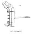
- FIG. 1shows a prior art illumination assembly for use with a medical device that retains a light source and one or more batteries;
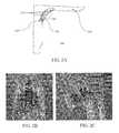
- FIGS. 2A-2Cshow an embodiment of a battery removal mechanism of the present invention illustrating separate disposal of batteries via an opening in the speculum or retractor blade;
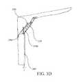
- FIGS. 3A-3Dshow a second embodiment of a battery removal mechanism of the present invention including a release switch
- FIG. 4shows a third embodiment of a battery removal mechanism of the present invention including a cover for the battery compartment;
- FIG. 5shows a fourth embodiment of a battery removal mechanism of the present invention in which one or more batteries are retained in a handle portion of the medical device and the handle portion includes a releasable platform;
- FIGS. 6A-6Dshow a variation of the fourth embodiment shown in FIG. 5 , including a pull switch for releasing the platform;
- FIGS. 7A-7Gshows another variation of the fourth embodiment shown in FIG. 5 , including a battery holding compartment with a pivotable platform;
- FIGS. 8A-8Bshows a fifth embodiment of a battery removal mechanism of the invention, including a rotatable ejection mechanism
- FIGS. 9A-9Bshows yet a sixth embodiment of a battery removal mechanism of the present invention in which batteries are retained in the handle portion and part of the handle portion retaining the batteries are breakable from the remainder of the handle portion;
- FIGS. 10A-10Bshow a medical device with a seventh embodiment of a battery removal mechanism of the present invention
- FIGS. 11A-11Bshow the seventh embodiment of the battery removal mechanism of FIGS. 10A-10B with a battery compartment in a retained state
- FIGS. 11C and 11Dshow a cross-sectional view of the medical device with the seventh embodiment of the present invention.
- FIGS. 12A-12Cshow the seventh embodiment of the battery removal mechanism of FIGS. 10A-10B with the battery compartment in an ejected state
- FIG. 13shows a rear faceplate portion of the medical device of FIGS. 11A-11D without the battery compartment;
- FIG. 14Ashows an exploded view of the medical device of FIGS. 10A-13 ;
- FIGS. 14B-14Gshow an illustrative sequence of assembling the medical device of FIGS. 10A-13 .
- an illumination assemblymay be defined by a structure (e.g., a housing or a casing) that retains at least a light source and a power supply.
- the illumination assemblyin some instances may further contain one or more conducting/non-conducting circuit elements, one or more energization/de-energization switch elements, engagement/retention elements, etc.
- FIG. 1shows an exemplary prior art illumination assembly 100 . Further structural and operational details regarding these types of illumination assemblies are described in at least U.S. patent application Ser. No. 14/316,787 (US Pub. No. 2014/0309499) and Ser. No. 15/178,744 (US Pub. No. 2016/0310121), both of which are incorporated herein by reference in their entireties.
- the housing that defines the illumination assembly 100is a semi-enclosed (or partially enclosing) structure having at least one open side allowing access to or removal of its constituents.
- the illumination assembly 100is configured to fully retain and securely hold the batteries and the contained light source upon placement of the illumination assembly 100 onto a surface of a blade.
- the surface upon with the illumination assemblyis placed (e.g., the speculum blade) provides the final, missing support for a full and complete retention.
- the illustrative illumination assembly 100is configured to attach to a speculum or retractor blade via suitable engagement means (e.g., clips, adhesives, slots and tabs, etc.).
- suitable engagement meanse.g., clips, adhesives, slots and tabs, etc.
- the position of attachment of the illumination assembly 100 along the bladevaries from anywhere between a distal end of the blade and a proximal end of the blade, or within or extending along a curved portion (transition into handle portion) of the blade.
- the illumination assembly 100is contained entirely within the handle portion of the medical device and the light is directed to a desired area, e.g., the distal end of the speculum or retractor blade, via use of light guiding means such as a light pipe.
- at least of a portion of the illumination assembly 100is external to the device or positioned on an exterior surface thereof, e.g., on the exterior surface of the speculum or retractor blade.
- the various embodiments of the present inventionincorporate a similar illumination assembly but are not necessarily limited to use of the illumination assembly 100 as shown in FIG. 1 .
- the embodiments of the present invention as described herein, as well as their respective variantsare compatible with illuminating means of any size, shape or structure.
- the embodiments of the present inventionare applicable to any medical or surgical device in which one or more of the entire medical or surgical device, the illuminating means, or the batteries are configured to be discarded after use.
- the embodiments of the present inventionare also applicable to any medical or surgical device which is battery-operated and uses batteries for powering another component of the device, not limited to a light source.
- the present inventionmay be used in an electrocautery device which uses power from batteries to heat an electrode tip.
- Other battery-powered medical devicesmay incorporate the present invention, and in particular, the battery removal mechanisms described herein.
- a medical devicesuch as a retractor or a speculum apparatus, having an outer housing and a battery-powered assembly, such as an illumination assembly, is provided, with the battery-powered assembly having a power source, e.g., one or more batteries, at least partially enclosed by the outer housing.
- the outer housing of the medical deviceincludes a handle and the medical device may further include at least one blade extending from the handle.
- the power source of the battery-powered assemblymay be provided in the handle or may be attached to the blade.
- the battery-powered assembly of certain embodimentsmay include a bottomless battery compartment.
- bottomless battery compartmentrefers to a compartment, which may be part of the battery-powered assembly, such as an illumination assembly, for retaining one or more batteries in which the compartment does not completely or permanently enclose the retained batteries. It is understood that the embodiments described below may be adapted for use with other medical and surgical devices, including but not limited to laryngoscopes, anoscopes, suction devices, electrocautery devices, and any other medical or surgical devices which use portable power sources, such as batteries or power packs.
- a speculum or retractor apparatus 200comprises a blade 210 , a handle, and an illumination assembly 220 attached to the blade 210 .
- the illumination assembly 220includes a bottomless battery compartment that retains one or more batteries 230 .
- the bottomless battery compartmentdoes not provide any retaining support for the batteries along at least one of its sides, e.g., the bottom side of the compartment that comes in contact with the surface of the blade 210 .
- the illumination assembly 220is a self-contained and standalone illumination assembly in which all of the batteries are at least loosely retained within the battery compartment by a small force (e.g., adhesive, spring, electromagnetic, etc.).
- a small outside forcee.g., shake, turbulence, push, jerk, etc.
- the illumination assembly 220firmly retains the batteries within the battery compartment and requires a force exceeding a certain threshold to cause the batteries to break loose via the open side of the battery compartment.
- the illumination assembly 220is configured such that the batteries are removable from the battery compartment without coming into physical contact with the user, the user's gloves, other instruments or outside surfaces of the apparatus that may have biohazardous matter thereon.
- the blade 210comprises an opening 240 that is aligned with the attachment position of the illumination assembly 220 .
- the opening 240 of the blade 210is typically defined by a size of a hole that is sufficiently large to allow at least the batteries 230 contained in the battery compartment to pass through and to be disposed.
- the opening 240permits only the batteries to pass through and be disposed. In other versions, the opening 240 may permit the entire illumination assembly to pass through and be disposed.
- the blade 210further comprises a cover 250 .
- the cover 250is typically provided on the external surface of the blade and covers the opening 240 . As shown in FIG. 2B , during a normal use of the apparatus 200 , the opening 240 is sealed by the cover 250 . The cover 250 in this state may be referred to herein as the “closed” position.
- the cover 250is provided via an adhesive that allows the cover 250 to be peeled off when disposal of the batteries is desired.
- the cover 250is a sticker that is placed over the opening 240 to secure the batteries 230 against its surface.
- the stickermay be coated so that the batteries 230 do not stick thereto but the sticker can be adhesively secured to the blade 210 .
- the cover 250is made of plastic material (e.g., same or similar substance as the blade). The plastic cover may be attached to the blade 210 via adhesives, hinges, latches, clips, rails, snaps, screws, or using other suitable techniques.
- the plastic covermay be articulated from the closed position to an “open” position by, for example, pressing onto the plastic cover, sliding the plastic cover, peeling the plastic cover, turning or rotating the plastic cover, etc.
- a buttonmay be used for releasing the cover when pressed.
- the cover 250is formed as part of the blade 210 itself.
- the cover 250is a hinged door that opens/closes the opening 240 or a sliding door that exposes the opening 240 for battery disposal.
- FIG. 2Cshows an example of the cover 250 in its “open” position.
- the illumination assembly 220 , the opening 240 and the cover 250may be positioned at the distal (front) end of the blade 210 , the center of the blade 210 , the proximal (rear) end of the blade 210 , or within the handle, or may extend along two or more of the portions of the blade. Regardless of position, the operation of the illumination assembly with respect to the opening and the cover remains the same or substantially similar.
- the usercan apply a force, such as shaking, pressing or bumping the apparatus, to “pop” the batteries 230 out from their retained position.
- a forcesuch as shaking, pressing or bumping the apparatus
- the batteries 230 and/or the illumination assembly 220can be detached from the blade 210 or the handle and can be disposed separately and safely from the rest of the apparatus 200 .
- no forceis necessary to remove the battery(ies) and, in such versions, the batteries fall out when the cover 250 is removed, peeled or otherwise in the open position.
- a band, ribbon or the likemay be passed behind the batteries and when the cover is removed, the band or ribbon is pulled to dislodge and release the batteries.
- the batteriesare removed from the retained position without requiring the user to physically contact the batteries and without coming into contact with other portions of the apparatus or other instruments that may be contaminated by biohazardous materials.
- An actuatorsuch as band, a ribbon, a biasing member or any other type of actuator, may be used for releasing the batteries from their retained position without having the user come into contact with the batteries.
- the batteriesare removed without making physical contact with outer or external surfaces of the apparatus which may be contaminated with biohazardous materials.
- the apparatus and its outer housingare configured to provide a direct path for releasing the power source with the path providing no contact with contaminated surfaces of the apparatus. This allows for proper disposal of the batteries separately from the remaining portions of the apparatus.
- a retractor or speculum apparatus 300includes a blade 310 , an illumination assembly 320 with one or more batteries 330 , an opening 340 and a battery compartment 350 for holding the one or more batteries.
- the structure and operation of the apparatus and the illumination assemblyare the same as those described in reference to FIG. 2A , and thus, further description thereof will be omitted. It is understood that although FIGS.
- 3A-3Dshow the illumination assembly 320 being disposed in the proximal end of the blade or in the area that joins the blade to the handle, in other embodiments, the illumination assembly may be provided in other areas of the blade, e.g., closer to the distal end, or in the handle portion of the apparatus in combination with a light guide or a similar device. It is also understood that this embodiment may be used with other battery-operated apparatuses, including those that do not include an illumination assembly.
- the battery compartment 350houses the one or more batteries used in the illumination assembly or in another battery-operated assembly, and is inserted into the opening 340 in the apparatus 300 .
- the battery compartment 350includes an opening 350 a at one end which allows the batteries 330 to be electrically coupled with other components, such as a light source of the illumination assembly, when the battery compartment 350 is in a closed state, and allows for removal of the batteries when the battery compartment 350 is in an open state.
- the battery compartment 350acts as a cover for the opening wherein the outer wall of the battery compartment 350 is coextensive with the walls of the blade and/or handle.
- the battery compartment 350is articulated by operating a release mechanism that includes a release tab 360 that can be moved from a first position in which the release tab 360 holds the battery compartment 350 in the closed state and a second position in which the release tab 360 allows the battery compartment 350 to drop down into an open state.
- the release tab 360is engaged with the battery compartment 350 at point 370 , but in other embodiments, the release tab 360 may be engaged with the battery compartment 350 at other points or other types of release mechanisms to move the battery compartment from the first position to the second position may be used.
- the release tab 360is coupled to a pull-down member 380 via a connection line 360 a , which extends down through the handle portion of the apparatus.
- the pull-down member 380may be inserted into or engaged with the distal end of the handle so as to form a cap or the like which can be easily removed from the handle by the user and pulled down so as to move the release tab 360 into the open state.
- the userpulls on the pull-down member 380 in the direction indicated by the arrow A 1 , causing the release tab 360 to move from the first position to the second position so as to cause the battery compartment 350 to articulate from its closed position to its open position and to cause the batteries 330 to be disposed in the direction indicated by the arrow A 2 through the opening 350 a in the battery compartment.
- the release tab 360opens a cover on the blade and only the batteries are disposed through the opening 350 a in the battery compartment.
- the battery compartment 350may be replaced with an illumination assembly compartment holding the entire illumination assembly so that the entire illumination assembly can be disposed via the opening 340 when the illumination assembly compartment is in the open state.
- the pull-down member 380is connected directly to the battery compartment 350 or the illumination assembly compartment, and when the pull-down member 380 is pulled, the battery compartment or the illumination assembly compartment is disengaged from the closed state and the batteries or the whole illumination assembly is disposed.
- FIG. 3Bshows an example of a pull-down member prior to activation
- FIG. 3Cshows an example of the pull-down member after activation in which the battery compartment is pushed through the opening of the blade.
- the pull-down membermay be freely hanging from the handle in some embodiments, while in other embodiments, the pull-down member may be engaged with the distal end of the cap to form an end cap or the like that is removable from the handle.
- the pull-down membermay be replaced by another activation mechanism, such as a switch or a pull-tab provided on the handle of the apparatus.
- the activation mechanismmay be disposed within the interior of the handle and is engaged or otherwise activated by placing a tool or a finger inside the handle from its open end.
- a switch, a button, a pull-tab, a pull-down member or any other suitable mechanismmay be provided on the interior of the handle or on the interior wall of the handle. In such embodiments, the activation mechanism cannot be accidentally triggered.
- the battery removal mechanismuses a battery compartment or an illumination assembly compartment which is articulated between the closed position and the open position so as to release the batteries and/or the illumination assembly from the apparatus for disposal.
- the battery removal mechanismmay use a cover for covering the opening 340 and for articulating between the first position in which the cover is closed and the batteries and/or illumination assembly are retained in the apparatus and the second position in which the cover is open and the batteries and/or illumination assembly can be removed from the apparatus through the opening 340 and disposed.
- the same or substantially similar release mechanismis used for causing the cover to articulate between the first and second positions.
- the batteriesmay be housed within a separately formed battery compartment so that when the cover is opened, the entire battery compartment with the batteries is removed.
- the whole illumination assemblyis housed within an illumination assembly compartment so that when the cover is opened, the illumination assembly compartment is removed, thus disposing of the entire illumination assembly.
- the batteriesare held in a partially open battery or illumination assembly compartment or case, which has an opening coextensive with the cover, so that when the cover is opened, the batteries drop down from the partially open compartment and can be disposed.
- the battery compartment 350includes one or more batteries 330 and an opening 350 b that opens into the handle portion of the apparatus.
- the battery compartment 350is further configured with a closing tab (or a “door”) 390 that holds the batteries 330 within the battery compartment 350 , when the closing tab 390 is in a closed state.
- the batteries 330rest on the closing tab 390 in the closed state.
- the batteriesare disposed in the area that connects the blade to the handle portion on an angle relative to the blade and to the handle portion.
- the batteriesmay be disposed in other areas of the apparatus, such as within the handle or in the blade area and the orientation of the batteries may be varied depending on the construction of the illumination assembly.
- the battery compartmentmay be provided in the handle portion in a substantially vertical orientation so that the batteries are supported by the closing tab 390 in the closed state.
- the closing tab 390is actuated from its closed state to an open state by pulling on the release tab 360 .
- the usercan pull on the release tab 360 that hangs loose through the handle portion causing the closing tab 390 to detach from the battery compartment 350 , allowing the batteries 330 to drop down through the handle portion of the speculum.
- the entire closing tab 390is detached.
- the closing tabonce detached, is also dropped through the handle portion.
- the detachment of the closing tab 390is only partial.
- pulling of the release tab 360partially breaks the attachment of the closing tab 390 to the battery compartment 350 and allows the closing tab 390 to remain partially attached to the battery compartment 350 (e.g., swinging via a hinge) to release the batteries via the handle portion.
- the closing tabmay be hingedly, rotatably or slidably connected to the battery compartment 350 or to the handle portion and may be held in the closed state until the release tab 360 is pulled.
- a spring membermay force the closing tab 390 into the closed state, while in other variations, the closing tab 390 may be mechanically coupled with the battery compartment 350 . Pulling of the release tab 360 in these versions would cause the closing tab 390 to rotate or to slide relative to the opening in the battery compartment into the open state so that the batteries can be dropped into and through the handle portion.
- the apparatusis configured such that when the battery compartment is or the closing tab is moved to the open position or removed, the batteries are released through the opening in the handle or through the open end of the handle portion without requiring physical contact between the user and the batteries.
- the batteriesare released without making physical contact with outer or external surfaces of the apparatus which may be contaminated with biohazardous materials.
- the battery removal mechanismmay be configured so as to inhibit or prevent reloading or replacement of the batteries into the battery compartment.
- the positioning of the battery compartmentdoes not allow easy access thereto so as to insert a new set of batteries or to reload the batteries after they are removed therefrom.
- the compartment and/or the closing tabare configured so that they cannot be returned back to the closed state after being articulated into the open state. As a result, such configurations ensure that the medical device apparatus is a single-use disposable apparatus and that the medical device cannot reused.
- a retractor or speculum apparatus 400similar to those described in reference to FIG. 2A , includes similar components such as the blade, the battery-operated assembly, such as an illumination assembly, with one or more batteries, an opening formed in the blade or handle, and a cover for the opening.
- the illumination assembly 420may include a bottomless battery compartment with an opening that corresponds to the opening in the blade or handle.
- the illumination assembly 420may be a self-contained illumination assembly with a housing that partially houses the illumination assembly and in which the one or more batteries are at least loosely retained by the housing by a small force.
- an opening in the housing for the illumination assemblycorresponds at least in part with the opening in the blade or handle.
- the opening in the blade or handleis covered by the cover 450 which may be formed from a plastic, polymer or rubber material.
- the cover 450is releasably attachable to the handle or blade or the apparatus. Any suitable fastening or attachment mechanism may be used for releasably attaching the cover to the handle or blade of the apparatus, including but not limited to providing protrusions and corresponding recesses or slots on the cover and handle or blade, using an adhesive to attach the cover to the handle or blade, or any suitable fastener.
- the cover 450may be completely removable from the handle or blade of the apparatus or in certain embodiments, the cover 450 may be hingedly connected to the handle or blade so as to open and close relative to the blade or handle.
- the cover 450may be elastic and squeezable, so that the cover is fitted into the opening in the handle or blade of the apparatus and can be removed by squeezing the cover on the sides to detach it from the opening.
- the cover 450covers at least the one or more batteries and retains them in the illumination assembly 420 .
- the cover 450is removed to expose the batteries, and the batteries can then be removed.
- a small outside forcesuch as a shake, or a jerk, applied to the apparatus, may be needed to remove the batteries.
- the cover 450forms an elastic and squeezable layer around a portion of the batteries so that the cover 450 is depressible or squeezable by the user for releasing the contained batteries. Specifically, pressing on the sides of the squeezable cover 450 forces the batteries to be released through the opening 440 and to be removed simultaneously with the cover 450 . The user can then dispose the batteries while holding the cover over the recycling container for the batteries.
- the coverhas to be articulated by sliding, rotating or the like so as to cause the batteries to be released and removed together with the cover.
- an apparatussuch as a speculum, retractor, laryngoscope, anoscope, suction device, or the like, is provided in which one or more batteries for powering a light source are provided within the handle portion thereof.
- the illumination assemblyis structured such that the batteries for powering the light source are retained in the handle portion and the light source is positioned along the blade or some other component of the apparatus where illumination is needed. The batteries are connected to the light source using wires.
- the illumination assemblyis structured such that the batteries and the light source are both retained in the handle portion and the light is directed to the area where illumination is needed, e.g., the distal end of the blade, using a light directing means (e.g., a light pipe, prism, mirrors, etc.).
- a light directing meanse.g., a light pipe, prism, mirrors, etc.
- the apparatus as shown in FIG. 5includes a handle portion 500 having an open-bottom receiving end 510 for receiving and retaining one or more batteries 520 .
- the open-bottom receiving end 510 of the handle portion 500is covered by a platform 530 that forms an end cap or end wall of the handle portion.
- the platform 530is hingedly (or rotatably) attached to the handle portion 500 via a hinge 540 , and is locked in place by a tab 545 and a release switch 550 .
- the tab 545When the release switch 550 is actuated in the direction indicated by the arrow C, the tab 545 is moved away from a closed position and the platform 530 drops down and rotates via the hinge 540 , which causes the batteries 520 retained in the handle portion to be disposed in the direction indicated by arrow D.
- this illustrative embodimentuses a tab 545 to hold the platform 530 in a closed position and to release the platform 530 into the open position, it is contemplated that other mechanisms may be used for retaining the platform 530 in the closed state and for releasing the platform to allow it to drop down.
- the batteries 520are merely resting upon the platform 530 when the platform is in its “closed” position and a biasing member, such as a spring, may be used to bias the batteries 520 in a direction of the platform 530 .
- the biasing memberacts as the actuator for releasing the batteries 520 from the apparatus.
- the spring 535is provided above the batteries and pushes the batteries toward the platform 530 .
- the release switch 550is actuated to open the platform 530 , the batteries are pushed out of the handle by the force of the spring 535 .
- the entire illumination assemblywhen the entire illumination assembly is positioned within the handle portion of the apparatus, all or a portion of the illumination assembly may be adhesively or mechanically attached to the handle portion.
- the batteriesmay be held by a bottomless battery compartment with an opening at the bottom covered by the platform 530 , or as shown in FIG. 5 , the handle portion may form the bottomless battery compartment that houses the batteries. In either case, when the platform 530 is opened, the batteries can drop down through the open-bottom receiving end 510 of the handle portion.
- the light source of the illumination assemblyis attached to the blade portion or some other portion of the apparatus where illumination is needed, and the batteries are retained in the handle portion of the apparatus, either in a separate bottomless compartment or in the handle portion itself forming the bottomless battery compartment that houses the batteries.
- the batteriesmay be held in place within the handle portion or within the separate bottomless compartment using a biasing member, an adhesive or some other retention force, but application of an external force to the apparatus causes the batteries to drop out when the platform 530 is opened.
- the apparatusmay further comprise one or more buttons or a separate switch that causes the batteries to drop loose.
- the battery removal mechanism of the embodiment of FIG. 5can be used with other types of medical devices that include a battery-operated assembly, whether or not the battery-operated assembly is an illumination assembly or another type of assembly.
- the apparatus shown in FIG. 6Acomprises similar components as the apparatus shown in FIG. 5 , but further comprises a pull switch 650 in place of the tab 545 and the release switch 550 as described with reference to FIG. 5 .
- the handle portion 600includes one or more slots or holes near its open-bottom receiving end 610 through which the pull switch 650 passes.
- the pull switch 650in its “closed” (or inserted) position, attaches to or otherwise secures to the platform 630 .
- FIG. 6Ashows the pull switch 650 holding the platform 630 at the top and bottom, in other variations, the pull switch 650 may hold only the bottom of the platform 630 .
- the pull switch 650may be inserted into a corresponding opening in the platform 630 side edge so as to hold it in the closed position, as shown in FIG. 6C .
- Any other type of engagement between the pull switch 650 and the platform 630may be used to releasably engage the pull switch 650 with the platform 630 in the closed state.
- a biasing membersuch as a spring member, may be used with the pull switch 650 to bias the pull switch 650 in the direction of the closed position. In this way, a predetermined pulling force on the pull switch 650 would be needed in order to disengage the pull switch 650 from the platform 630 so as to prevent accidental opening of the platform 630 .
- FIGS. 6B-6Cshow different perspective views of the apparatus as shown and described in FIG. 6A .
- the entire platform 630may pass through slots formed in opposing walls of the handle portion.
- the platform 630having a length that traverses the entire width of the handle portion and provides a resting surface for the batteries, is provided in place of the platform-and-the-pull-switch combination shown in FIG. 6A .
- corresponding slotsare provided in opposing walls of the lower end of the handle portion allowing the platform to be pulled in either direction.
- the platformmay be pulled only in one direction and may be prevented from being pulled in the other direction, e.g., by a flange or the like. Similar to the foregoing versions, once the platform 630 is removed, the batteries drop through the open end of the handle portion.
- the batterieswhen the platform is operated to the open state or removed, the batteries are released through the open end of the handle portion without requiring physical contact between the user and the batteries. In addition, the batteries are released without making physical contact with outer surfaces of the apparatus which may be contaminated with biohazardous materials.
- the platformmay be articulated from its closed position to open position via different methods.
- the release switchmay be an external push button or a pull tab that releases the platform.
- FIGS. 7A-7Ga variation that includes a battery holding compartment with a pivotable platform is shown in FIGS. 7A-7G .
- a battery holding compartment 740is used for housing the batteries therein and for coupling the batteries, e.g., using wires, to the light source or to any other component of the apparatus that requires power supply.
- the battery compartment 740is inserted into an open end at the bottom of the handle portion of the apparatus.
- FIGS. 7A-7Cshow a separate battery holding compartment 740 for housing the batteries and for releasing the batteries from the apparatus, in other embodiments, the handle portion may be configured to house the batteries directly therein and a similar pivotable platform mechanism may be used at the bottom of the handle portion as the one shown in FIGS. 7A-7C .
- a bottom end of the battery holding compartment 740is provided with an opening 710 , which may be circular in cross section or any other suitable shape, and a mating portion 720 , which in this illustrative example is shown as a protrusion.
- a pivotable platform 730is provided, with the pivotable platform 730 having a pivoting end 730 a and a mating end 730 b .
- the pivoting end 730 apivotably engages with the opening 710 formed on the bottom end of the battery holding compartment 740 .
- the mating end 730 b and the mating portion 720form a lock for retaining the pivotable platform 730 in a closed state when the mating end 730 b engages with the mating portion 720 so as to lock the pivotable platform 730 relative to the battery holding compartment 740 .
- the mating portion 720 of the battery holding compartment 740is formed as a protrusion extending outwardly from a sidewall of the battery holding compartment 740 .
- the mating end 730 b of the pivotable platform 730includes a locking tooth 732 that mates with the mating portion 720 so as to lock the pivotable portion 730 in the closed state, and further includes an operating tab 734 which can be operated by a user to release the mating between the locking tooth 732 and the mating portion 720 .
- the operating tab 734is actuated by a user (e.g., by pressing)
- the lock between the locking tooth 732 of the pivotable platform 730 and the mating portion 720is released and the pivotable platform 730 may be pivoted into the open state relative to a pivot point at the pivot end 730 a .
- the mating portion 720may be formed as a recess so that the locking tooth 732 of the mating end 730 b is inserted into the mating portion 720 recess in the closed state.
- Other configurations of the mating portion 720 and the mating end 730 bmay be used for providing a lock (a locking mechanism) for locking the pivotable platform 730 to the battery holding compartment 740 .
- the pivotable platform 730 in its “closed” positionprovides a surface on which one or more batteries rest within the battery holding compartment 740 .
- the batteriesare electrically connected to a distantly positioned light source via electrical wires extending through the handle portion. In other medical devices, the batteries are electrically connected to other battery-powered components of a battery-operated assembly provided in the device.
- the pivotable platform 730is released from engagement with the mating portion 720 via an external force applied to the operating tab 734 at the mating end 730 b .
- the pivotable platform 730then pivots via the pivoting end 730 a and permits the batteries to drop through the open bottom of the speculum handle portion.
- a spring or another type of biasing memberi.e., an actuator
- an actuatormay be provided at the top of the batteries so as to bias the batteries in the direction of the opening in the battery holding compartment, i.e., in the direction of the pivotable platform 730 .
- the batterieswhen the platform is pivoted to the open position, the batteries are released from the battery holding compartment without requiring physical contact between the user and the batteries. In addition, the batteries are released without making physical contact with outer surfaces of the apparatus which may be contaminated with biohazardous materials.
- the pivotable platform 730is configured together with a battery holding compartment 740 as a standalone structure.
- the battery holding compartmentis sized and/or shaped such that it is insertable (or fittable) into the hollow end of the handle portion.
- the mating portionis included on the battery compartment 740 .
- the usercan actuate, by operating the operating tab 734 , the mating end 730 b of the pivotable platform 730 to pivot the platform to its open position.
- the mating portionmay be provided on the handle portion instead of on the battery compartment 740 .
- FIGS. 7E-7Gshow respective bottom views of the foregoing examples of FIGS. 7B-7D .
- the battery holding compartment 740includes openings or recesses 710 in opposing walls thereof at the lower end.
- the pivotable platform 730includes a pair of legs or shafts 736 projecting from the sides of the platform at or near the pivoting end 730 a . The legs 736 are inserted into the corresponding openings or recesses 710 in the walls of the battery holding compartment 740 .
- the openings or recesses 710have a smaller cross-section than the thickness of the legs 736 at an initial point of insertion, with the cross-section increasing to accommodate the thickness of the legs.
- the legs 736 of the platform 730snap into the openings or recesses 710 , and can be prevented from disengaging from the openings or recesses 710 .
- the body of the platformmay be narrower than the opening in the battery holding compartment 740 as long as the platform 730 can retain the batteries within the battery holding compartment 740 and prevent contamination of the batteries with biohazardous materials.
- the body of the platform 730is the same width or wider than the opening in the battery holding compartment 740 .
- a platform 730 with a greater width than the opening in the battery holding compartment 740may further protect the batteries from contamination with biohazardous materials, particularly in medical devices in which the handle may be exposed to biohazardous materials during use.
- FIGS. 8A-8Bshow a cross-sectional view looking axially down a handle portion having a battery ejection mechanism for removing batteries disposed within the handle portion through an opening 850 formed in a sidewall of the handle portion.
- the ejection mechanismincludes a door 830 that covers the opening 850 in the handle portion and includes with an ejection lever 835 extending partially around the batteries housed within the handle portion.
- the door 830is pivotable around a pivot point P between a closed state, shown in FIG. 8A , and an open state shown in FIG. 8B .
- the door 830also includes an operation tab 830 a which can be operated (e.g., by pressing) by a user to open the door 830 so as to move it from the closed state to the open state.
- the ejection lever 835which moves together with the door 830 , pushes the batteries through the opening 850 in the handle, thereby ejecting the batteries from the apparatus.
- the door 830is in its closed state.
- the door 830 and the ejection lever 835are structured and/or shaped in a manner such that the one or more batteries can be released (or pulled) through an side opening 840 formed between the door 830 and the ejection lever 835 using a small force or without using any force.
- the door 830 and the ejection lever 835may be made of elastic material and the size of the side opening 840 is smaller than the diameter of the retained batteries.
- a small forcesuch as a tap on the handle or a shake, would be required to release the batteries when the door 830 is in the open state.
- the door 830 and the ejection lever 835are made from plastic or polymer materials and the size of the side opening 840 is the same or larger than the diameter of the batteries. In this version, no force is needed to release the batteries when the door is in the open state. In any case, when the door is operated to the open state, the power source is released via the opening 840 without requiring physical contact between the user and the power source. In addition, the power source is released without making physical contact with outer surfaces of the apparatus which may be contaminated with biohazardous materials.
- FIG. 8Billustrates the batteries being released in the direction indicated by arrow “F.” As a variation to the embodiment shown in FIGS.
- a column-shaped structure(hereinafter “structure”) with a hollow center and sidewalls for retaining and partially enclosing one or more batteries may be provided in the handle portion.
- the structuremay have a platform for supporting the one or more batteries thereon, with the platform being connected to the sidewalls so as to be movable together with the rest of the structure.
- the structureis sized to be insertable and pivotable through the opening 850 in the handle portion of the apparatus relative to the pivot point P.
- the cross-section of the sidewalls of the structureis substantially the same or similar to that of the door and ejection lever shown in FIG. 8A . Similar to the door and the ejection lever shown in FIG.
- the structureincludes a circumferential sidewall that covers the opening 850 in the handle portion of the apparatus and extends around the one or more batteries but does not completely encircle the batteries.
- the circumferential sidewallincludes an opening that allows the retained batteries to be released therethrough when the structure is rotated from the closed state to the open state.
- the rotation of the structure about the pivot point and the release mechanism for the batteries in the structureare similar to those described with respect to FIGS. 8A and 8B .
- the release switch shown in FIG. 6Amay be an external push button that releases the platform.
- the platform shown in FIG. 6Dmay include further components that can be pushed or pulled to assist in articulation of the platform to its open position.
- the handle portion of the apparatusis configured such that at least a portion thereof is breakable or detachable from the rest of the handle portion.
- the apparatus 900includes a handle portion 910 in which a lower end portion 920 is breakable or detachable from the remaining portion of the handle portion 910 .
- one or more batteriesare retained within the lower end portion 920 that is breakable or detachable from the rest of the handle portion 910 .
- the breakable lower end portion 920completely detaches from the rest of the handle portion 910 .
- a hinge 930is provided between the breakable lower end portion 920 and the rest of the handle portion 910 such that when the breakable lower end portion 920 is articulated to be “broken off” or detached from the handle portion 910 , the breakable lower end portion 920 hinges via the hinge 930 and the one or more batteries retained therein are released and can be disposed.
- FIG. 9Billustrates disposal of the batteries when the breakable lower end portion 920 is separated from the rest of the handle portion of the apparatus and hinges via the hinge 930 .
- Actuation of the breakable lower end portion 920 as described hereinmay be enabled using a variety of different methods such as manual force (pressing, twisting, pulling, etc.), a pull switch, a push button, or other similar techniques.
- the breakable lower end portion 920cannot be reconnected and returned to the previous state of being attached to the upper portion of the handle. As a result, reloading or replacement of the batteries for additional use of the apparatus, after the batteries are removed and disposed, is inhibited. This facilitates disposability and one-time use of the apparatus and prevents reuse of the apparatus. In addition, after the breakable lower end portion 920 is separated, the batteries are released through the open end of the handle portion without requiring physical contact between the user and the batteries, and without making physical contact with outer surfaces of the apparatus which may be contaminated with biohazardous materials.
- a platform placed at the bottom end of the handle portion of the medical deviceis opened in one of many different ways to allow the batteries to be disposed separately and quickly and without requiring physical contact between the user and the batteries and without the batteries making physical contact with outer surfaces of the apparatus which may be contaminated.
- the blade or handle of the medical deviceincludes an opening through which the batteries held in a bottomless battery compartment of an illumination assembly are disposed separately and quickly.
- portions of the medical device that retains the batteriesare detached completely or partially from the medical device itself.
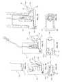
- FIGS. 10A-10Gshow another embodiment of a medical device, and in this illustrative embodiment, a speculum 1000 , which includes a battery removal mechanism that uses a battery compartment or holder 1060 (also referred to as a “battery sled”) provided in a handle 1034 of the speculum 1000 .
- the battery compartment 1060holds batteries 1074 within the handle 1034 in a retained state, which is the operating state of the speculum, and allows the batteries 1074 to be released and disposed through an opening in a bottom of the handle in an ejected state.
- FIGS. 10A-10Gshow another embodiment of a medical device, and in this illustrative embodiment, a speculum 1000 , which includes a battery removal mechanism that uses a battery compartment or holder 1060 (also referred to as a “battery sled”) provided in a handle 1034 of the speculum 1000 .
- the battery compartment 1060holds batteries 1074 within the handle 1034 in
- the same or similar battery removal mechanismmay be provided in another type of medical device that uses batteries, including but not limited to a retractor, an anoscope, a laryngoscope, a nasal speculum, an otoscope, an aural speculum, a suction device, a cannula or any other examination and/or surgical device which uses one or more batteries.
- a retractoran anoscope, a laryngoscope, a nasal speculum, an otoscope, an aural speculum, a suction device, a cannula or any other examination and/or surgical device which uses one or more batteries.
- the medical devices in which the battery removal mechanism may be usedare not limited to medical devices with an illumination assembly and the battery removal mechanism may be used in any battery-operated medical device with a battery operated assembly, such as an electrocautery device.
- FIGS. 10A-10Bshow a general assembled configuration of the speculum 1000 of this embodiment.
- the speculum 1000includes an upper member 1020 comprising an upper blade 1022 and an operating mechanism 1027 , a lower member 1030 comprising a lower blade 1032 , a handle 1034 and a rear faceplate assembly 1036 that engages with the handle 1034 , and a linear support member 1050 which hingedly engages with the upper member 1020 for angular adjustment between the upper and lower blades, and slidably engages with the rear faceplate assembly 1036 for vertical adjustment between the upper and lower blades.
- the battery removal mechanismis used with a different type of a medical device, the general configuration of the medical device would be different.
- a retractor, laryngoscope or anoscope medical devicewould typically include a handle and a blade and in some configurations, may include a rear faceplate assembly similar to the rear faceplate assembly 1036 of FIGS. 10A-10B that engages with the handle.
- the general configurations of other types of medical devicesmay be adjusted as needed for the functioning of the medical device.
- the speculum 1000includes an illumination assembly 1070 comprising at least one light source 1072 , such as an LED or similar light emitting device, one or more batteries 1074 and wires (not shown) electrically connecting the light source 1072 with the one or more batteries.
- the illumination assemblymay also include an activation device (not shown), which can be in a form of a pull tab, a button, a switch, a motion detector or the like, for activating the light source 1072 from an OFF state to an ON state and vice versa.
- the rear face plate assembly 1036includes a rear faceplate 1037 that engages with sidewalls of the handle 1034 and forms a rear wall of the handle 1034 .
- the rear faceplate assembly 1036also includes a shelf portion 1038 which extends from an upper end of the rear faceplate 1037 and an illumination assembly cover 1039 which extends from the shelf portion 1038 .
- the illumination assembly cover 1039extends along an inner surface of a front wall of the handle 1034 and along a curved portion 1033 that connects the handle and the lower blade 1032 .
- the illumination assembly cover 1039is open on the side that abuts the inner surface of the handle 1034 and the curved portion 1033 , and encloses the wires connecting the batteries 1074 and the light source 1072 . In this illustrative embodiment, the illumination assembly cover 1039 also partially encloses the light source 1072 , which protrudes from an end of the illumination assembly cover 1039 . In the present illustrative embodiment, the illumination assembly cover 1039 is engaged with the curved portion 1033 using tabs formed on the illumination assembly cover that engage with corresponding slots formed in the curved portion 1033 . However, in other embodiments, the illumination assembly cover 1039 may engage with the handle 1034 and/or with the lower blade 1032 .
- the illumination assembly 1070is configured so that the light source 1072 is positioned adjacent the curved portion 1033 of the lower member. However, in other embodiments, the light source 1072 may be positioned closer to the lower blade 1032 or adjacent the lower blade 1032 , at any location along the length of the lower blade 1032 .
- the illumination assembly cover 1039may extend further than in the embodiments shown in FIGS. 10A-10B .
- the illumination assembly cover 1039may extend along a portion of the lower blade 1032 .
- the illumination assembly cover 1039may also function as a smoke evacuation channel and may extend along the lower blade 1032 toward the distal end of the blade 1032 .
- FIGS. 11A-11D and 12A-12Cshow the rear faceplate assembly 1036 together with the battery compartment 1060 and the illumination assembly 1070 .
- the battery compartment 2060is in the retained or operating state
- FIGS. 12A-12Cthe battery compartment is in the ejected state.
- FIG. 13shows the rear face plate assembly 1036 without the battery compartment.
- the rear faceplate 1037includes a plurality of engagement portions 1037 a protruding from an inner surface thereof and configured to engage with corresponding protrusions formed on the inner side of the handle sidewalls.
- the protruding engagement portions 1037 amay engage with a channel or one or more recesses formed in each of the handle sidewalls.
- the inner surface of the rear faceplate 1037includes a plurality of stop tabs 1037 b for engagement with a lock tooth of the linear support member for vertical adjustment.
- the rear faceplate 1037may include a plurality of stop tabs on an opposing, outer surface thereof.
- the rear faceplate 1037includes a through recess 1037 c extending along its length which is used for sliding the linear adjustment member therein so as to provide for vertical adjustment.
- the rear faceplatealso includes rail portions 1037 e protruding from the inner surface thereof and extending on each side of the through opening. The rail portions 1037 e guide the linear support member 1050 when it is inserted into the through recess 1037 c .
- the battery compartment 1060comprises a housing 1062 for holding the batteries 1074 in the retained state, and an operating member 1064 , which can be operated by a user to cause the housing 1062 to move from the retained state to the ejected state.
- the operating member 1064is a button protruding from the top surface of the housing and in an assembled state of the speculum, extending from a proximal end of the handle.
- the shelfhas a pair of sidewalls 1040 extending from a lower surface of the shelf and surrounding the batteries 1074 held by the battery compartment 1060 in the retained state.
- the sidewalls 1040together with the housing 1062 of the battery compartment 1060 hold the batteries 1074 in place and prevent dislodgement of the batteries.
- One or both of the sidewalls 1040may include coupling elements attached thereto for electrically coupling the batteries 1074 to the wires.
- one or more biasing memberse.g., a spring, may be used to hold the batteries 1074 in place between the sidewalls 1040 .
- FIGS. 11C-11Dshow a cross-section of the speculum in which battery compartment 1060 is engaged with the rear face plate assembly 1036 in the retained state.
- the housing 1062is a C-shaped housing which has an open side and holds the batteries 1074 against a projection 1035 formed on an inner front surface of the handle.
- the batteries 1074are held in the C-shaped housing 1062 and are supported from the opposite side by the projection 1035 formed on the inner surface of the handle.
- the batteries 1074are also retained in their position by the sidewalls 1040 shown in FIGS. 11A-11B .
- the projection 1035may be shaped as a beam with a plurality of ribs traversing the beam, as shown in FIGS. 11C and 12B .
- the shape of the projection 1035may vary depending on the type of batteries used and the arrangement of the batteries in the housing 1062 .
- the battery compartment 1060is locked in place relative to the rear face plate 1037 by a locking mechanism.
- the locking mechanismis a snap arm 1037 d formed at a top portion of the rear faceplate 1037 which includes an arm having some flexibility/elasticity and a lock tooth which engages with the bottom surface of the battery compartment 1060 .
- the top surface of the housing 1062 of the battery compartmentprevents the battery compartment from moving in an upward direction relative to the rear faceplate 1037 and the snap arm 1037 d prevent the battery compartment 1060 from moving in a downward direction relative to the rear faceplate 1037 .
- FIG. 13shows a more detailed view of the snap arm 1037 d , which is formed in the rear faceplate 1037 and extends into the through recess 1037 c in the rear faceplate 1037 .
- the button 1064may include a lip formed at or near its top surface, with the periphery of the lip being greater than the opening in the shelf 1038 . The lip would prevent the button 1064 from being pushed through the opening in the shelf 1038 past the lip and from falling out together with the batteries.
- Other types of retaining meansmay be used for preventing the battery compartment from falling out when the button is moved to the ejected state.
- the operating member 1064includes a notch 1064 a or a recess in its surface that faces the rear faceplate 1037 when assembled.
- This notch 1064 aengages the snap arm 1037 d in the ejected state to prevent removal of the battery compartment 1060 from the speculum.
- the snap arm 1037 ddisengages from the bottom of the housing 1062 and the battery compartment 1060 is moved from the retaining state to the ejected state shown in FIGS. 12A-12C .
- FIG. 12Ashows the rear face plate assembly 1036 together with the battery compartment 1060 in the ejected state
- FIGS. 12B-12Cshow a cross-sectional view of the speculum 1000 with the battery compartment 1060 in the ejected state.
- the batteries 1074are no longer pressed against the projection 1035 on the inner surface of the handle and are removed from the space between the sidewalls 1040 that extend from the shelf 1038 . Since the batteries are no longer retained on all sides by the housing 1062 , the sidewalls 1040 and the projection 1035 , they can be easily dislodged from the housing 1062 and removed from the open bottom end of the handle 1034 .
- the handle 1034is shaped so that the handle is smaller in circumference in the area of the projection 1035 and larger in circumference in the area below the projection 1035 .
- the front wall of the handleprotrudes outwardly below the projection 1035 .
- This configurationprovides additional space for releasing the batteries from the housing 1062 and for allowing the batteries to easily fall through the handle to be removed from the bottom opening in the handle.
- the batteriesare removed from the open bottom end of the handle 1034 without requiring physical contact between the user and the batteries, and also without the batteries coming into physical contact with external surfaces of the speculum which may be contaminated with biohazardous materials.
- the battery compartment 1060is locked in place in the ejected state by the snap arm 1037 d , which is engaged with the notch 1064 a in the operating member 1064 .
- the locking of the battery compartment 1060also inhibits the battery compartment from being returned to the retained state from the ejected state.
- the operating member 1064is pressed or pushed by the user into the proximal end of the handle to move the battery compartment into the ejected position.
- the useris prevented from accessing the operating member 1064 and from returning the operating member 1064 and the battery compartment 1060 to the retained state.
- the batteries in the embodiment of FIGS. 10-12are removed though the open bottom end of the handle, other variations are also contemplated.
- the batteriesmay be removed from a cutout formed in one of the sidewalls of the handle 1034 or from a cutout formed in the rear faceplate 1037 .
- the operating member 1064 in the embodiments of FIGS. 10-12is configured as a push-button.
- a pulling mechanismmay instead be used to pull the battery compartment 1060 downward so as to release the batteries from the battery compartment.
- FIGS. 10-12show the battery removal mechanism being used in a speculum, it is understood that this mechanism may be adapted for use in other devices, such as retractors, laryngoscopes, anoscopes, suction devices, electrocautery pens and other medical devices which use batteries, whether or not the batteries are used for an illumination assembly or any other type of battery operated assembly.
- the battery removal mechanismmay be adapted for use in a surgical retractor or laryngoscope by omitting the upper member 1020 and the linear support member 1050 and using a substantially the same mechanism for battery removal in a retractor or laryngoscope that includes a handle 1034 , a blade extending at an angle with respect to the handle and the rear faceplate assembly 1036 as described above (similar to FIG. 10B ).
- the battery removal mechanismmay be adapted for use in an anoscope by omitting the upper member 1020 and the linear support member 1050 and by modifying the shape of the lower blade.
- FIGS. 14A-14Gshow an exploded view of the speculum, which includes the lower member 1030 with the handle 1034 and the lower blade 1032 , the upper member 1020 with the upper blade 1022 and an operating member 1027 , the linear support member 1050 , the rear faceplate assembly 1036 together with the battery compartment 1060 , batteries 1074 , a rocker 1160 for angular adjustment, a biasing member 1164 and a pivot pin 1162 for attaching the rocker 1160 .
- FIGS. 14B-14Gshow an illustrative sequence of assembling the speculum of FIGS. 10-13 .
- the battery compartment 1060is assembled with the rear faceplate assembly 1036 by inserting the button 1064 into the opening in the shelf 1038 of the rear faceplate assembly 1036 .
- the snap arm 1037 dengages with the bottom surface of the housing 1062 .
- the batteries 1074are inserted into the housing 1062 , as shown in FIG. 14C , and are held by the housing and between the sidewalls 1040 extending from the shelf 1038 .
- battery contactsare loaded to allow for connection of the batteries to wires.
- FIG. 14Cbattery contacts are loaded to allow for connection of the batteries to wires.
- the light source 1072is positioned to be held by the end of the illumination assembly cover 1039 and the wires are loaded to connect the light source 1072 to the battery contacts and to be enclosed by the illumination assembly cover 1039 .
- the illumination assembly 1070is assembled together with the rear faceplate assembly 1036 and the battery compartment 1060 .
- the resulting assembly of FIG. 14Cis then assembled together with the lower member 1020 .
- the rear faceplate assembly 1036snaps into the rear of the handle 1034 of the lower member 1020 to form the rear wall of the handle 1034 .
- the engagement protrusions 1037 a on the inner surface of the rear faceplate 1037snap to engage with corresponding protrusions 1034 a formed on the inner surface of the handle sidewalls.
- other types of engagementmay be used for assembling the rear faceplate assembly 1036 with the lower member 1020 .
- the sidewalls of the handlemay include channels formed on the inner surfaces thereof for engagement with the engagement protrusions 1037 a on the rear faceplate 1037 by sliding the engagement protrusions 1037 a into the channels.
- the sidewalls of the handlemay include recesses for engaging with the engagement protrusions 1037 a .
- the sidewalls of the handlemay include protrusions that engage with corresponding recesses formed in the rear faceplate 1037 .
- Other types of engagementsmay be used for coupling the faceplate assembly 1036 with the lower member 1020 .
- the rocker 1160 of the angular adjustment mechanismis assembled with the operating member 1027 .
- the rocker 1160is positioned with openings therein to align with corresponding openings in the operating member 1027 and a spring 1164 or any other suitable biasing member is positioned between the operating member and the rocker 1160 so as to bias the rocker 1160 in a direction away from the operating member 1027 .
- the pin 1162is then inserted into the openings in the rocker 1160 and the corresponding openings in the operating member 1027 .
- the ends of the pin 1162may be flattened or capped to prevent removal of the pin.
- the biasing member 1164may be positioned between the operating member 1027 and the rocker 1160 either before or after insertion of the pin to hold the rocker 1160 and the operating member 1027 together.
- the top member 1020is assembled together with the linear support member 1050 .
- hinge protrusions 1022 aare formed on the outer sides of a proximal end of the upper blade 1022 .
- the linear support member 1050includes a yoke portion (U-shaped portion) extending from its elongated body with each leg of the yoke portion including an opening for engaging with the corresponding hinge protrusion 1022 a .
- the hinge protrusions 1022 aare snapped into corresponding openings in the yoke portion for a hinge coupling therebetween.
- the legs of the yoke portionmay include inwardly facing protrusions and the proximal end of the blade 1022 may include corresponding openings for insertion of the protrusions on the yoke portion.
- Other types of couplingsmay be used to form a hinge coupling between the upper member 1020 and the linear support member 1050 .
- FIG. 14Gthe top assembly formed in FIG. 14F is then assembled together with the bottom assembly formed in FIG. 14D by inserting the linear support member 1050 into the through recess 1037 c formed in the rear faceplate 1037 .
- the engagement arm 1058 of the linear support member 1050is inserted into the through recess 1037 c and slid below the through recess 1037 c so that the locking tooth 1059 on the engagement arm 1058 engages with stop tabs formed on the inner surface of the rear faceplate 1037 .
- the retaining projection 1052 a on the elongated body 1052 of the linear support member 1050engages with the rear faceplate assembly 1036 to prevent removal and disengagement of the linear support member 1050 from the rear faceplate assembly 1036 .
- the resulting disposable speculum 1000has mechanical engagements between the different elements, which makes the speculum easy to assemble and which are sufficiently strong to withstand in-use conditions.
- the order in which the elements of the speculum 1000 are assembledare not limited to the order shown in FIGS. 14B-14G , and may be varied.
- the materials used for forming the medical device of FIGS. 10-14may be plastic, polymer, metallic or other materials.
- the components of the medical deviceare formed from plastic materials.
- Exemplary plastic materials that may be used for constructing the medical device of the present inventioninclude, but are not limited to, polypropylene, polystyrene, and any composite of more than one of these plastics and polymers.
- the blade member(s), the handle and the rear faceplate assemblymay be molded from a colorless transparent or translucent plastic material, such as acrylic plastic, polycarbonate or the like.
- the rocker used in the speculum described abovemay be made from the same or similar materials as the speculum or from metallic materials.
- the linear support member of the speculum described abovemay be formed from a polyester or polyamide material, such as nylon, or the like.
- the biasing member(s) (spring) and the pinmay be formed from metallic materials or from polymers and plastics. All of these components may be formed by injection molding, extrusion, using a 3D printer or any other suitable technique.
- the materials for forming the medical deviceincluding the blade(s), the handle, the rear faceplate assembly, the rocker and/or the linear support member, of the present invention include glass-fiber reinforced polymers, polyarylamide compounds, thermoplastic crystalline polymers, thermoplastic crystalline polymers of aromatic diamines and aromatic dicarboxylic anhydrides, glass-fiber reinforced polyarylamides, and other materials having sufficient rigidity and strength.
- plastic and/or polymer materialsare used for the components of the speculum, in other embodiments, some or all of the components may be formed from metallic or fiberglass materials.
- the battery removal mechanismsmay be used with other medical devices that use batteries, either as part of the illumination assembly or as part of another assembly that requires batteries.
- other variationsmay be made for safe removal of batteries without contaminating them with biological (biohazardous) materials, as would be appreciated to those of ordinary skill in the art. Therefore, it is to be understood that other expedients/variations may be employed but that stay within the meaning, scope and spirit of the invention.
Landscapes
- Health & Medical Sciences (AREA)
- Life Sciences & Earth Sciences (AREA)
- Surgery (AREA)
- Engineering & Computer Science (AREA)
- Physics & Mathematics (AREA)
- Optics & Photonics (AREA)
- General Health & Medical Sciences (AREA)
- Public Health (AREA)
- Nuclear Medicine, Radiotherapy & Molecular Imaging (AREA)
- Veterinary Medicine (AREA)
- Biomedical Technology (AREA)
- Heart & Thoracic Surgery (AREA)
- Medical Informatics (AREA)
- Molecular Biology (AREA)
- Animal Behavior & Ethology (AREA)
- Pathology (AREA)
- Radiology & Medical Imaging (AREA)
- Biophysics (AREA)
- Gynecology & Obstetrics (AREA)
- Reproductive Health (AREA)
- Otolaryngology (AREA)
- Physiology (AREA)
- Pulmonology (AREA)
- Microelectronics & Electronic Packaging (AREA)
- Endoscopes (AREA)
- Battery Mounting, Suspending (AREA)
Abstract
Description
Claims (28)
Priority Applications (3)
| Application Number | Priority Date | Filing Date | Title |
|---|---|---|---|
| US16/139,813US10441155B2 (en) | 2017-10-19 | 2018-09-24 | Medical devices with battery removal |
| PCT/US2018/054925WO2019079059A1 (en) | 2017-10-19 | 2018-10-09 | Medical devices with battery removal and speculum with continuous adjustment |
| US16/586,304US10912455B2 (en) | 2017-10-19 | 2019-09-27 | Medical devices with battery removal |
Applications Claiming Priority (4)
| Application Number | Priority Date | Filing Date | Title |
|---|---|---|---|
| US201762574412P | 2017-10-19 | 2017-10-19 | |
| US201762574969P | 2017-10-20 | 2017-10-20 | |
| US201862649190P | 2018-03-28 | 2018-03-28 | |
| US16/139,813US10441155B2 (en) | 2017-10-19 | 2018-09-24 | Medical devices with battery removal |
Related Child Applications (1)
| Application Number | Title | Priority Date | Filing Date |
|---|---|---|---|
| US16/586,304ContinuationUS10912455B2 (en) | 2017-10-19 | 2019-09-27 | Medical devices with battery removal |
Publications (2)
| Publication Number | Publication Date |
|---|---|
| US20190117042A1 US20190117042A1 (en) | 2019-04-25 |
| US10441155B2true US10441155B2 (en) | 2019-10-15 |
Family
ID=66170317
Family Applications (6)
| Application Number | Title | Priority Date | Filing Date |
|---|---|---|---|
| US16/105,153ActiveUS10278572B1 (en) | 2017-10-19 | 2018-08-20 | Speculum |
| US16/139,813ActiveUS10441155B2 (en) | 2017-10-19 | 2018-09-24 | Medical devices with battery removal |
| US16/402,580Active2039-03-11US11253145B2 (en) | 2017-10-19 | 2019-05-03 | Speculum |
| US16/586,304ActiveUS10912455B2 (en) | 2017-10-19 | 2019-09-27 | Medical devices with battery removal |
| US17/212,506Active2041-06-15US12383129B2 (en) | 2017-10-19 | 2021-03-25 | Medical devices with battery removal |
| US18/524,428PendingUS20240108211A1 (en) | 2017-10-19 | 2023-11-30 | Speculum |
Family Applications Before (1)
| Application Number | Title | Priority Date | Filing Date |
|---|---|---|---|
| US16/105,153ActiveUS10278572B1 (en) | 2017-10-19 | 2018-08-20 | Speculum |
Family Applications After (4)
| Application Number | Title | Priority Date | Filing Date |
|---|---|---|---|
| US16/402,580Active2039-03-11US11253145B2 (en) | 2017-10-19 | 2019-05-03 | Speculum |
| US16/586,304ActiveUS10912455B2 (en) | 2017-10-19 | 2019-09-27 | Medical devices with battery removal |
| US17/212,506Active2041-06-15US12383129B2 (en) | 2017-10-19 | 2021-03-25 | Medical devices with battery removal |
| US18/524,428PendingUS20240108211A1 (en) | 2017-10-19 | 2023-11-30 | Speculum |
Country Status (2)
| Country | Link |
|---|---|
| US (6) | US10278572B1 (en) |
| WO (1) | WO2019079059A1 (en) |
Cited By (1)
| Publication number | Priority date | Publication date | Assignee | Title |
|---|---|---|---|---|
| US20200022574A1 (en)* | 2017-10-19 | 2020-01-23 | Obp Medical Corporation | Medical devices with battery removal |
Families Citing this family (5)
| Publication number | Priority date | Publication date | Assignee | Title |
|---|---|---|---|---|
| US11547291B2 (en)* | 2019-02-27 | 2023-01-10 | Welch Allyn, Inc. | Integrated illumination assembly for handheld medical devices |
| CN110251063B (en)* | 2019-07-04 | 2021-10-26 | 吴芝芝 | Household vaginal dilator |
| TWI727740B (en)* | 2020-04-15 | 2021-05-11 | 貞安有限公司 | Therapeutic endoscope and cover thereof |
| CN112674826B (en)* | 2021-01-13 | 2022-01-14 | 苏州法兰克曼医疗器械有限公司 | Cavity mirror cutting anastomat with adjustable direction of keeping silent |
| CN115089105B (en)* | 2022-07-11 | 2025-09-12 | 苏州桑田医疗科技有限公司 | A locking and unlocking structure for an expander |
Citations (341)
| Publication number | Priority date | Publication date | Assignee | Title |
|---|---|---|---|---|
| US559122A (en) | 1896-04-28 | Endoscopic instrument | ||
| US2235979A (en) | 1940-06-03 | 1941-03-25 | Albert L Brown | Surgical and diagnostic instrument |
| US2247458A (en) | 1939-05-19 | 1941-07-01 | Gen Steel Castings Corp | Railway truck |
| US2482971A (en) | 1947-07-11 | 1949-09-27 | Golson Kelly Kendall | Self-illuminated transparent proctoscope |
| US2592190A (en) | 1948-08-27 | 1952-04-08 | Nat Electric Instr Company Inc | Illuminated speculum |
| US3324850A (en) | 1964-04-08 | 1967-06-13 | Aubern Instr Corp | Illuminated vaginal speculum with rotatable cam pivoting and locking means |
| US3332414A (en) | 1964-01-20 | 1967-07-25 | Monarch Molding Inc | Vaginal speculum having selectively locked angular and vertical blade adjustment means |
| US3426749A (en)* | 1965-05-20 | 1969-02-11 | Longworth Scient Instr Co Ltd | Disposable cover for laryngoscope blade |
| US3532088A (en) | 1966-02-23 | 1970-10-06 | Bio Analytical Labor Inc | Speculum instrument |
| US3592199A (en) | 1970-02-09 | 1971-07-13 | Medical Products Corp | Autoclavable surgical instrument illumination |
| US3595222A (en) | 1967-06-13 | 1971-07-27 | William Noel Vellacott | Laryngoscope |
| US3598113A (en)* | 1968-10-09 | 1971-08-10 | Welch Allyn Inc | Disposable laryngoscope construction |
| US3638644A (en) | 1969-03-05 | 1972-02-01 | Michael Elbert | Illuminated surgical speculum |
| US3675641A (en) | 1969-11-21 | 1972-07-11 | Bio Analytical Labor Inc | Speculum instrument and isolated light means therefor |
| DE2128855A1 (en) | 1971-06-11 | 1972-12-28 | Manning, Claus Reinhard, 4006 Erkrath-Unterbach | Speculum for instrumental diagnosis of the vagina |
| US3716047A (en) | 1970-12-21 | 1973-02-13 | Welch Allyn Inc | Disposable light-conductive speculum |
| US3729006A (en) | 1971-05-27 | 1973-04-24 | M Kanbar | Disposable surgical retractors |
| US3762400A (en) | 1971-10-26 | 1973-10-02 | Donald B Mc | Medical examining instrument |
| US3769968A (en) | 1971-11-22 | 1973-11-06 | L Blount | Speculum |
| US3789835A (en) | 1972-03-16 | 1974-02-05 | R Whitman | Illuminating attachments for vaginal speculum |
| US3815585A (en) | 1971-01-14 | 1974-06-11 | Bio Analytical Labor Inc | Disposable vaginal speculum |
| US3826248A (en) | 1971-09-21 | 1974-07-30 | G Gobels | Laryngoscope |
| US3851642A (en) | 1971-10-26 | 1974-12-03 | Medical Testing Syst Inc | Medical examining instrument |
| US3934578A (en) | 1974-05-28 | 1976-01-27 | Propper Manufacturing Co., Inc. | Direct illumination otoscope |
| US3945371A (en) | 1972-05-26 | 1976-03-23 | Stuart Lee Adelman | Apparatus for inspection and sampling in restricted aperture cavities employing fibre optics |
| US3978850A (en) | 1975-03-24 | 1976-09-07 | Welch Allyn, Inc. | Medical diagnostic instruments |
| US4067323A (en) | 1975-12-02 | 1978-01-10 | Concept Inc. | Light for vaginal speculum |
| US4156424A (en) | 1978-05-01 | 1979-05-29 | Burgin Kermit H | Locking adjustable speculum |
| US4210133A (en) | 1975-10-21 | 1980-07-01 | Consejo Nacional De Ciencia Y Tecnologia | Vaginal microscope |
| US4226228A (en) | 1978-11-02 | 1980-10-07 | Shin Hee J | Multiple joint retractor with light |
| US4300541A (en) | 1979-02-09 | 1981-11-17 | Kermit Burgin | Speculum lens structure |
| FR2490478A1 (en) | 1980-09-24 | 1982-03-26 | Chouraqui Albert | Speculum with built-in illumination - has light source mounted on inside surface of blade powered by battery lamp or laser |
| US4337763A (en) | 1980-04-21 | 1982-07-06 | The United States Of America As Represented By The Department Of Health, Education And Welfare | Illuminated surgical instrument |
| US4432351A (en) | 1980-06-26 | 1984-02-21 | Institute For Industrial Research And Standards | Vaginal speculum |
| US4492220A (en) | 1982-11-15 | 1985-01-08 | Hayes Allen L | Vaginal speculum protector |
| US4502468A (en) | 1979-12-20 | 1985-03-05 | Burgin Kermit H | Adjustable speculum with incorporated lighting system |
| US4527553A (en) | 1980-04-28 | 1985-07-09 | Upsher Michael S | Laryngoscope with improved light source |
| US4546761A (en) | 1983-01-12 | 1985-10-15 | Mccullough Cartwright Pharmaceutical Corp. | Large animal speculum holder and battery-powered illuminator |
| US4562832A (en) | 1984-01-21 | 1986-01-07 | Wilder Joseph R | Medical instrument and light pipe illumination assembly |
| US4566439A (en) | 1984-07-16 | 1986-01-28 | Burgin Kermit H | Acrylooptic examination device with auxiliary light |
| US4574784A (en) | 1984-09-04 | 1986-03-11 | Soloway David J | Laryngoscope |
| US4596239A (en)* | 1985-04-10 | 1986-06-24 | General Medical Products, Inc. | Light source for illuminating and examining devices |
| US4597383A (en) | 1985-04-25 | 1986-07-01 | Luxtec Corporation | Fiber-optic illuminated vaginal speculum |
| EP0190014A2 (en) | 1985-01-23 | 1986-08-06 | The Trylon Corporation | Medical instruments and illuminating attachments |
| US4607623A (en) | 1984-11-08 | 1986-08-26 | Jack Bauman | Unitary insert support frame for the handle of an examining device |
| US4619248A (en) | 1984-08-22 | 1986-10-28 | Walsh David J | Light attachment for speculum |
| US4638792A (en) | 1979-12-20 | 1987-01-27 | Burgin Kermit H | Adjustable speculum with incorporated lighting system |
| US4766887A (en) | 1986-06-19 | 1988-08-30 | Welch Allyn, Inc. | Disposable vaginal speculum |
| US4807600A (en) | 1986-10-15 | 1989-02-28 | Hayes Allen L | Speculum protector |
| US4884559A (en) | 1987-12-04 | 1989-12-05 | Collins Jason H | Surgical speculum |
| US4901708A (en)* | 1988-07-22 | 1990-02-20 | Lee Tzium Shou | Viewing laryngoscope |
| US4905670A (en) | 1988-12-28 | 1990-03-06 | Adair Edwin Lloyd | Apparatus for cervical videoscopy |
| US4934352A (en) | 1982-10-22 | 1990-06-19 | Sullivan Jr Eugene M | Surgical retractor handle construction |
| US4971036A (en) | 1987-12-04 | 1990-11-20 | Collins Jason H | Vaginal speculum |
| US5018507A (en) | 1990-01-26 | 1991-05-28 | Montaldi David H | One-piece disposable speculum |
| US5026368A (en) | 1988-12-28 | 1991-06-25 | Adair Edwin Lloyd | Method for cervical videoscopy |
| US5054906A (en) | 1986-01-17 | 1991-10-08 | Brimfield Precision, Inc. | Indirectly illuminating ophthalmological speculum |
| US5063908A (en) | 1989-06-02 | 1991-11-12 | Collins Jason H | Adapter for cervical speculum |
| US5143054A (en) | 1988-12-28 | 1992-09-01 | Adair Edwin Lloyd | Cervical videoscope with detachable camera unit |
| US5165387A (en) | 1991-02-04 | 1992-11-24 | Transidyne General Corporation | Endoscope with disposable light |
| US5174278A (en) | 1990-11-26 | 1992-12-29 | Beth Babkow | Downward rotating speculum with conical shaped blades |
| US5179937A (en) | 1988-02-04 | 1993-01-19 | Lee Chenault D | Disposable vaginal speculum |
| US5179938A (en) | 1983-02-17 | 1993-01-19 | The Trylon Corporation | Apparatus for endoscopic examination of body cavity using chemiluminescent light source |
| US5222271A (en) | 1992-07-09 | 1993-06-29 | Eganhouse Thomas J | Speculum cleaner |
| USD337384S (en) | 1991-01-14 | 1993-07-13 | Teleflex, Inc. | Laryngoscope blade |
| US5318009A (en) | 1993-03-03 | 1994-06-07 | Scientific Medical Programs, Inc. | Illuminated tongue depressor |
| US5427152A (en) | 1991-09-21 | 1995-06-27 | Hydac Technology Gmbh | Hydraulic accumulator with dividing wall supported by connecting and retaining parts |
| US5438976A (en) | 1993-11-29 | 1995-08-08 | Nash; Jeanne L. | Teeth protector for laryngoscope blade |
| US5465709A (en) | 1993-11-10 | 1995-11-14 | Advanced Medical Products Inc. | Illuminated vaginal speculum |
| US5499964A (en) | 1994-09-16 | 1996-03-19 | Welch Al Iyn, Inc. | Speculum with smoke evacuation channel |
| US5512038A (en) | 1993-11-15 | 1996-04-30 | O'neal; Darrell D. | Spinal retractor apparatus having a curved blade |
| CN2239235Y (en) | 1995-06-16 | 1996-11-06 | 张淑文 | Anus colposcope |
| CN2265156Y (en) | 1996-03-28 | 1997-10-22 | 商加瑞 | Endoscope with illumination for medical use |
| US5695492A (en) | 1995-04-11 | 1997-12-09 | Brown; Alan W. | Lamellar illumination apparatus for eye surgery |
| US5716329A (en) | 1996-09-30 | 1998-02-10 | Dieter; Michael A. | Disposable expandable speculum |
| WO1998025512A1 (en) | 1996-12-13 | 1998-06-18 | Solution S.A.S. | Light and handle device for vaginal speculum |
| US5785648A (en) | 1996-10-09 | 1998-07-28 | David Min, M.D., Inc. | Speculum |
| US5840013A (en) | 1994-03-18 | 1998-11-24 | Lee; Jai S. | Method of introducing a tubular member at a site in the body |
| US5846249A (en) | 1996-02-07 | 1998-12-08 | Pinotage, Llc | Video gynecological examination apparatus |
| US5865729A (en) | 1997-10-10 | 1999-02-02 | Olympus America, Inc. | Apparatus for facilitating gynecological examinations and procedures |
| US5873820A (en) | 1995-07-04 | 1999-02-23 | Norell; Nils-Erik | Vaginal speculum |
| US5879304A (en) | 1993-11-12 | 1999-03-09 | Truphatek International Ltd. | Single use laryngoscope blade |
| US5888195A (en) | 1998-03-26 | 1999-03-30 | Schneider; Cary N. | Laryngoscope blade |
| US5899854A (en) | 1998-04-20 | 1999-05-04 | University Of New Mexico | Speculum and method for inserting an elongated instrument into an animal's body |
| US5916150A (en) | 1997-08-29 | 1999-06-29 | Sillman; Jonathon S. | Speculum for simultaneously viewing and removing obstructions |
| US6004265A (en) | 1999-03-01 | 1999-12-21 | Hsu; Jin-Cherng | Vaginal speculum with light guide means |
| US6036638A (en) | 1997-11-04 | 2000-03-14 | Nwawka; Chudi C. | Vaginal sleeve |
| US6036713A (en) | 1996-01-24 | 2000-03-14 | Archimedes Surgical, Inc. | Instruments and methods for minimally invasive vascular procedures |
| US6048308A (en) | 1999-03-30 | 2000-04-11 | Strong; John E. | Vaginal speculum |
| US6080105A (en) | 1997-06-26 | 2000-06-27 | Spears; Robert A. | Illuminated dental and surgical retractor and kit including plurality of blades and blades recharging base |
| US6130520A (en) | 1998-03-13 | 2000-10-10 | Welch Allyn, Inc. | Diagnostic instrument system |
| US6176824B1 (en) | 1996-10-29 | 2001-01-23 | James M. Davis | Fiberoptically illuminated appliances |
| US6186944B1 (en) | 1998-11-25 | 2001-02-13 | Jory Tsai | Medical inspection device |
| US6217512B1 (en) | 1997-12-12 | 2001-04-17 | Program For Appropriate Technology In Health | Self-illuminated, non-invasive, visual cervical inspection apparatus and method |
| US6231505B1 (en) | 1999-09-20 | 2001-05-15 | Tyson Edward Martin | Laryngoscope blade |
| US6254247B1 (en) | 1999-01-14 | 2001-07-03 | Redgate Industries, Inc. | Illuminable containers and method |
| US6277067B1 (en) | 1997-04-04 | 2001-08-21 | Kerry L. Blair | Method and portable colposcope useful in cervical cancer detection |
| US20010029044A1 (en) | 1999-11-29 | 2001-10-11 | Gombrich Peter P. | Cervical screening system |
| US6319199B1 (en) | 1998-10-26 | 2001-11-20 | David M. Sheehan | Portable data collection device |
| US6346085B1 (en) | 2000-06-27 | 2002-02-12 | Noah I. Schiffman | Soft tissue biopsy instrument |
| US20020022769A1 (en) | 1999-03-03 | 2002-02-21 | Smith Vincent A. | Portable video laryngoscope |
| US6359644B1 (en) | 1998-09-01 | 2002-03-19 | Welch Allyn, Inc. | Measurement system for video colposcope |
| US6361489B1 (en) | 1998-11-25 | 2002-03-26 | Jory Tsai | Medical inspection device |
| US20020038075A1 (en) | 1998-11-25 | 2002-03-28 | Jory Tsai | Medical inspection device |
| US6379296B1 (en) | 1999-03-26 | 2002-04-30 | Richard W. Baggett | Medical lighting device |
| US6379299B1 (en) | 2000-05-04 | 2002-04-30 | German Borodulin | Vaginal speculum with adjustable blades |
| US20020055670A1 (en) | 2000-10-17 | 2002-05-09 | Sol Weiss | Surgical instrument |
| US6394111B1 (en) | 1997-06-11 | 2002-05-28 | Ethicon, Inc. | Detection of cleanliness of a medical device during a washing process |
| US6416465B2 (en) | 2000-04-14 | 2002-07-09 | Salvador A. Brau | Surgical retractor and related surgical approach to access the anterior lumbar region |
| US6428180B1 (en) | 1999-07-20 | 2002-08-06 | Mickey M. Karram | Surgical illumination device and method of use |
| US6432045B2 (en) | 2000-03-31 | 2002-08-13 | Artes Medical | Urethra surgical device |
| US6432049B1 (en) | 2000-08-29 | 2002-08-13 | Linda Kay Banta | Adjustable vaginal speculum light |
| US6436033B2 (en) | 1997-09-09 | 2002-08-20 | Mca Medical Products Pty Ltd. | Speculum |
| RU2187972C2 (en) | 2000-04-13 | 2002-08-27 | Военно-медицинский институт Федеральной пограничной службы Российской Федерации при Нижегородской государственной медицинской академии | Phlebotome device |
| US6450952B1 (en) | 1998-04-23 | 2002-09-17 | Scimed Life Systems, Inc. | Medical body access device |
| CN2516109Y (en) | 2002-01-07 | 2002-10-16 | 刘振秀 | Vaginal speculum with lighting device |
| US6468232B1 (en) | 2000-07-13 | 2002-10-22 | The Regents Of The University Of Michigan | Method and apparatus for measuring properties of the pelvic floor muscles |
| US6468206B1 (en) | 1998-05-01 | 2002-10-22 | Genzyme Corporation | Illuminated surgical retractor |
| US20020156350A1 (en) | 2001-02-27 | 2002-10-24 | German Nieto | Disposable speculum with included light and mechanisms for examination and gynecological surgery |
| US20020165435A1 (en) | 2000-10-17 | 2002-11-07 | Sol Weiss | Attachment devices for surgical instruments |
| US6487440B2 (en) | 1998-07-08 | 2002-11-26 | Lifespex, Inc. | Optical probe having and methods for difuse and uniform light irradiation |
| US20020198471A1 (en) | 2001-06-08 | 2002-12-26 | Cervilenz, Inc. | Devices and methods for cervix measurement |
| US6504985B2 (en) | 1995-06-27 | 2003-01-07 | Lumitex, Inc. | Illuminated surgical retractor |
| US6523973B2 (en) | 1999-08-16 | 2003-02-25 | Robert D. Galli | Miniature flashlight |
| US20030095781A1 (en) | 1997-07-02 | 2003-05-22 | Williams Jeffrey B. | Illuminated surgical retractor |
| US6569091B2 (en) | 2000-05-04 | 2003-05-27 | Ananias Diokno | Disconnectable vaginal speculum with removeable blades |
| US20030139673A1 (en) | 2002-01-18 | 2003-07-24 | Vivenzio Robert L. | Illumination system |
| US6616603B1 (en) | 2000-09-01 | 2003-09-09 | Sergio Bicocchi | Anoscope |
| US20030176772A1 (en) | 2002-03-12 | 2003-09-18 | Yang Yeong Fang | Disposable vaginal speculum having light device |
| US20030187331A1 (en) | 2002-02-22 | 2003-10-02 | Jeremy Faludi | Ergonomic otoscope with efficient light |
| WO2003082123A2 (en) | 2002-03-28 | 2003-10-09 | Imre Jordy | Medical instrument for holding open an intervention site and a method for producing the same |
| US6676598B2 (en) | 1999-05-21 | 2004-01-13 | Karl Storz Gmbh & Co. Kg | Laryngoscope |
| US20040026829A1 (en) | 2000-05-23 | 2004-02-12 | Clemens Van Der Weegen | Manufacture of dome-shaped articles from thermoplastic foam sheet material technical field |
| US20040054260A1 (en) | 1999-12-24 | 2004-03-18 | Klaassen Bernard Wilhelm Geziena Nicolaas | Vaginal speculum |
| US6719688B2 (en) | 2001-11-19 | 2004-04-13 | Truphatek International Limited | Light guide mount for use with a laryngoscope |
| DE202004002963U1 (en) | 2004-02-26 | 2004-04-22 | Aesculap Ag & Co. Kg | Lighting element for a surgical instrument has a connecting device to make a detachable fastening for the lighting element on the instrument |
| US6761687B1 (en) | 1999-12-17 | 2004-07-13 | Umesh C. P. Doshi | Speculum |
| US20040141175A1 (en) | 2002-07-12 | 2004-07-22 | Leo Baldwin | Method and apparatus for uniform lighting source |
| CN2629738Y (en) | 2003-06-18 | 2004-08-04 | 赵桂强 | Light-source type disposable vaginal dilator |
| WO2004064624A1 (en) | 2003-01-21 | 2004-08-05 | Metech S.R.L. | A retractor for operations on the arteria haemorroidalis |
| US20040186355A1 (en) | 2003-03-21 | 2004-09-23 | Welch Allyn, Inc. | Protective sheath for illumination assembly of a disposable vaginal speculum |
| US20040183482A1 (en) | 2003-03-20 | 2004-09-23 | Welch Allyn, Inc. | Electrical adapter for medical diagnostic instruments using leds as illumination sources |
| US20040184288A1 (en) | 2003-03-21 | 2004-09-23 | Welch Allyn, Inc. | Illumination assembly having fluid-tight seal |
| CN2668152Y (en) | 2003-12-04 | 2005-01-05 | 华中科技大学同济医学院附属协和医院 | Disposable light guide vaginal dilator |
| CN1565664A (en) | 2003-06-18 | 2005-01-19 | 赵桂强 | Disposable vaginal dilator with illuminating source |
| US20050065496A1 (en) | 2002-03-06 | 2005-03-24 | Simon James S. | Chemiluminescently illuminated suction appliances |
| US20050085723A1 (en) | 2003-10-04 | 2005-04-21 | Joel Huebner | Radiolucent medical devices with radiopaque markers |
| US20050085699A1 (en) | 2000-10-17 | 2005-04-21 | Sol Weiss | Attachment devices for surgical instruments |
| US6896653B1 (en) | 2002-03-07 | 2005-05-24 | Science For Medical Advocates, Inc. | Personal pelvic viewer |
| US20050159649A1 (en) | 2004-01-16 | 2005-07-21 | Patel Rajeev J. | Laryngoscope and associated method of intubating a patient |
| US20050192482A1 (en) | 2004-01-30 | 2005-09-01 | Endoluminal Therapeutics, Inc. | Disposable sheath for specula |
| US20050215858A1 (en) | 2002-03-07 | 2005-09-29 | Vail William B Iii | Tubular personal pelvic viewers |
| US20050240081A1 (en) | 2004-04-22 | 2005-10-27 | The Cleveland Clinic Foundation | Laryngoscope blade |
| US20050277811A1 (en) | 2004-05-25 | 2005-12-15 | Innovative Gynecological Solutions, Llc | Speculum |
| US7029439B2 (en) | 2002-07-09 | 2006-04-18 | Welch Allyn, Inc. | Medical diagnostic instrument |
| US20060084843A1 (en) | 2004-09-30 | 2006-04-20 | Codman & Shurtleff, Inc. | Disposable padding for a self-retaining retraction device |
| DE202005019780U1 (en) | 2005-01-12 | 2006-04-20 | Hidde, Gregor | Surgical hook assembly has an electrical and/or pneumatic and/or mechanical separation point between hand grip andhook shank |
| USD520464S1 (en) | 2003-03-21 | 2006-05-09 | Welch Allyn, Inc. | Illuminator switch assembly |
| US20060189847A1 (en)* | 2003-02-11 | 2006-08-24 | Anaesthesia Airways Pty Limited | Single use laryngoscope |
| US20060200186A1 (en) | 2005-03-04 | 2006-09-07 | Marchek Connie P | Adjustable access device for surgical procedures |
| WO2006107878A2 (en) | 2005-04-01 | 2006-10-12 | Welch Allyn, Inc. | Illumination assembly for use with vaginal speculum apparatus |
| US20070043264A1 (en) | 2004-05-25 | 2007-02-22 | Innovative Gynecological Solutions, Llc | Speculum |
| US20070060938A1 (en) | 2005-09-15 | 2007-03-15 | Dziadik Stephen P | Vessel harvesting apparatus |
| US20070060795A1 (en) | 2005-09-14 | 2007-03-15 | Spotlight Surgical, Inc. | Lighted surgical retractors with LED illumination light engines |
| US20070093693A1 (en)* | 2005-10-21 | 2007-04-26 | Vital Signs, Inc. | Laryngoscope and laryngoscope handle apparatus including an LED and which may include an ergonomic handle |
| US20070100212A1 (en) | 2004-10-08 | 2007-05-03 | Nuvasive, Inc. | Surgical access system and related methods |
| US7223223B2 (en) | 2003-06-05 | 2007-05-29 | Bescorp, Inc. | Method of folding and stacking multiple sheet sets |
| US20070179342A1 (en)* | 2006-01-12 | 2007-08-02 | Kb Port Llc | Wireless Laryngoscope with Internal Antennae and One Piece Construction Adapted for Laryngoscopy Training |
| US20070208226A1 (en) | 2006-01-18 | 2007-09-06 | Spotlight Surgical, Inc. | Retractor illumination system |
| US20070230164A1 (en) | 2006-04-03 | 2007-10-04 | Welch Allyn, Inc. | Vaginal speculum assembly having portable illuminator |
| US20070230167A1 (en) | 2006-04-03 | 2007-10-04 | Welch Allyn, Inc. | Power connections and interface for compact illuminator assembly |
| RU2308873C2 (en) | 2003-01-21 | 2007-10-27 | МЕТЕК С.р.Л. | Retractor for carrying out operations on rectal artery |
| US20070255110A1 (en) | 2006-04-28 | 2007-11-01 | Maine Medical Center | Operative vaginal speculum |
| US20070270866A1 (en) | 2006-04-13 | 2007-11-22 | General Electric Company | Percutaneous Registration-and-Access Tool for Minimally Invasive Spinal Surgery |
| DE60033612T2 (en) | 1999-10-06 | 2007-12-06 | Johnson & Johnson Professional, Inc. | Surgical retractor with controlled rotational movement |
| US20080002426A1 (en) | 2006-06-13 | 2008-01-03 | Spotlight Surgical, Inc. | Film illumination system |
| CN201055387Y (en) | 2007-07-02 | 2008-05-07 | 张小军 | Vein stripping hook |
| CN101179982A (en) | 2005-04-01 | 2008-05-14 | 韦尔奇阿林公司 | Vaginal speculum apparatus |
| US20080221569A1 (en) | 2007-03-08 | 2008-09-11 | Depuy Products, Inc. | Orthopaedic instrumentation with integral load-bearing members |
| US20080269564A1 (en) | 2007-04-17 | 2008-10-30 | Coopersurgical, Incorporated | Surgical retractor system and method |
| US20080278936A1 (en) | 2007-05-07 | 2008-11-13 | Pressure Pruducts Medical Supplies, Inc. | Surgical lights freely positionable in the operating theater |
| US20090018400A1 (en) | 2003-12-18 | 2009-01-15 | Depuy Spine, Inc. | Surgical retractor systems and illuminated cannulae |
| US20090069634A1 (en) | 2007-09-06 | 2009-03-12 | Daniel Larkin | Vaginal speculum including collapsible and expandable frame |
| US20090097236A1 (en) | 2007-10-15 | 2009-04-16 | Utah Medical Products, Inc. | Disposable medical-examination light |
| US20090112068A1 (en) | 2007-10-24 | 2009-04-30 | Spotlight Surgical, Inc. | Blade Insert Illuminator |
| US20090275603A1 (en) | 2002-05-31 | 2009-11-05 | Michigan State University | NF- kB Inhibitors And Uses Thereof |
| WO2009137017A2 (en) | 2008-05-05 | 2009-11-12 | Ranier Limited | Distractor |
| US20090287192A1 (en) | 2005-04-01 | 2009-11-19 | Vivenzio Robert L | Medical diagnostic instrument having portable illuminator |
| US20090312610A1 (en) | 2008-06-13 | 2009-12-17 | Obp Corporation | Disposable Speculums Having Single-Sided Support and Operating Mechanism |
| US20100036382A1 (en) | 2006-12-26 | 2010-02-11 | Solvay Advanced Polymers, L.L.C. | Orthopedic tool made of a plastic material |
| US20100041955A1 (en) | 2008-08-13 | 2010-02-18 | Invuity, Inc. | Cyclo Olefin Polymer and Copolymer Medical Devices |
| US7736304B2 (en) | 2004-02-29 | 2010-06-15 | Truphatek International Ltd. | Metal laryngoscope blade |
| US20100191062A1 (en) | 2009-01-23 | 2010-07-29 | Lucan Miles Kieffer | Battlefield laryngoscope adaptor cap for flashlight |
| US20100292533A1 (en) | 2009-05-14 | 2010-11-18 | Terumo Cardiovascular Systems Corporation | Endoscopic Cutter with Reconfigurable Guides |
| US20110022032A1 (en)* | 2007-10-05 | 2011-01-27 | Tyco Healthcare Group Lp | Battery ejection design for a surgical device |
| US7909759B2 (en) | 2004-11-23 | 2011-03-22 | Truphatek International Ltd | Handheld penknife-like laryngoscope |
| US7967809B2 (en) | 2008-05-28 | 2011-06-28 | Obp Corporation | Self-sealing assembly for preventing fluid leakage from medical device |
| US8012089B2 (en) | 2006-05-22 | 2011-09-06 | Ardeshir Bayat | Disposable expandable cordless lighted retractor |
| US20110257650A1 (en)* | 2007-12-03 | 2011-10-20 | Derek Dee Deville | Battery Assembly for Battery-Powered Surgical Instruments |
| US8047987B2 (en) | 2006-05-26 | 2011-11-01 | Invuity, Inc. | Blade insert illuminator |
| US20120055470A1 (en) | 2005-03-08 | 2012-03-08 | Truphatek International Ltd. | Intubation stylet |
| US20120059226A1 (en) | 2010-09-01 | 2012-03-08 | Funt David K | Surgical retractors with illumination |
| US8142353B2 (en) | 2004-02-29 | 2012-03-27 | Truphatek International Ltd. | Metal laryngoscope blade with illumination assembly |
| US20120078060A1 (en) | 2010-09-28 | 2012-03-29 | Obp Corporation | Disposable speculum having lateral stabilizing mechanism |
| CN102415869A (en) | 2010-07-15 | 2012-04-18 | Thd股份公司 | Medical device for colorectal lesions |
| US8162826B2 (en) | 2007-03-11 | 2012-04-24 | Truphatek International Ltd. | Laryngoscopes and rechargeable illumination units for use therewith |
| US20120116170A1 (en) | 2010-10-08 | 2012-05-10 | Invuity, Inc. | Method and apparatus for soft tissue retraction |
| CN102573700A (en) | 2009-05-18 | 2012-07-11 | 纽姆克斯股份有限公司 | Cross-sectional changes of an elongated lung volume reducing device during deployment |
| US8251898B2 (en) | 2007-08-07 | 2012-08-28 | Truphatek International Ltd | Laryngoscope apparatus with enhanced viewing capability |
| US20120277780A1 (en)* | 2007-12-03 | 2012-11-01 | Covidien Ag | Cordless Hand-Held Ultrasonic Cautery Cutting Device |
| US20120330103A1 (en)* | 2008-06-23 | 2012-12-27 | Intubrite, Llc | Laryngoscope and Method of Use |
| US20130018230A1 (en) | 2011-07-13 | 2013-01-17 | Chi Mei Medical Center | Surgical retractor having a lighting unit |
| US20130021798A1 (en) | 2011-07-22 | 2013-01-24 | Excellence Optoelectronics Inc. | Light shielding plate of outdoor led lighting device |
| US20130041229A2 (en) | 2010-09-29 | 2013-02-14 | Alfred E. Mann Institute For Biomedical Engineering At The University Of Southern California | Minimally obstructive retractor |
| US20130046290A1 (en)* | 2008-11-06 | 2013-02-21 | Covidien Ag | Two-Stage Switch for Surgical Device |
| WO2013044151A1 (en) | 2011-09-23 | 2013-03-28 | Invuity, Inc. | Illuminated and modular soft tissue retractor |
| US20130092421A1 (en) | 2010-05-27 | 2013-04-18 | Nippon Mektron, Ltd. | Flexible circuit board |
| US20130197313A1 (en) | 2012-01-31 | 2013-08-01 | Shaw P. Wan | Surgical retractor with light |
| CN302536685S (en) | 2013-02-27 | 2013-08-14 | Obp医学公司 | anal guide |
| US8512234B2 (en) | 2011-04-07 | 2013-08-20 | Truphatek International Ltd. | Laryngoscope assembly with enhanced viewing capability |
| US8555892B2 (en) | 2009-09-28 | 2013-10-15 | Obp Corporation | Mayo stand drape with self-disposing feature |
| US20130281784A1 (en) | 2012-04-23 | 2013-10-24 | Stephen P. RAY | Surgical sleeve suction retractor |
| US8628879B2 (en) | 2006-10-09 | 2014-01-14 | Truphatek International Ltd. | Magnetic resonance (MR) conditional medical equipment for use in MR environments |
| WO2014041172A1 (en) | 2012-09-14 | 2014-03-20 | Corlife Ohg | Lighting device for surgical purposes |
| US20140088371A1 (en) | 2009-11-10 | 2014-03-27 | Invuity, Inc. | Illuminated suction apparatus |
| CN203591245U (en) | 2013-08-15 | 2014-05-14 | Obp医学公司 | Laryngoscope structure |
| CN103925266A (en) | 2014-04-17 | 2014-07-16 | 宝钢发展有限公司 | Large plastic plate matching structure based on cantilever buckles |
| US20140202459A1 (en) | 2013-01-22 | 2014-07-24 | Swengg Co. | Intubation device |
| US8821385B2 (en) | 2012-03-21 | 2014-09-02 | Olympus Medical Systems Corp. | Endoscope and helical rotation member attached to insertion unit of this endoscope |
| US20140275790A1 (en) | 2013-03-15 | 2014-09-18 | Welch Allyn, Inc. | Illumination device, system, and method of use |
| US20140309499A1 (en) | 2010-09-28 | 2014-10-16 | Obp Corporation | Speculum |
| US20140316211A1 (en) | 2013-04-18 | 2014-10-23 | Rainer Hermle | Medical Instrument |
| CN203898367U (en) | 2014-04-15 | 2014-10-29 | 张新红 | Anus drag hook |
| US20140323800A1 (en) | 2010-12-23 | 2014-10-30 | Mayo Foundation For Medical Education And Research | Vessel dissection and harvesting apparatus, systems and methods |
| US20140364695A1 (en) | 2011-09-29 | 2014-12-11 | Alfred E. Mann Inst for Biomedical Engineering at the University of Southern California | Speculum for obstetrical and gynecological exams and related procedures |
| USD719652S1 (en) | 2013-02-27 | 2014-12-16 | Obp Medical Corporation | Anal speculum with introducer and built-in disposable light source |
| US20140371536A1 (en)* | 2011-12-09 | 2014-12-18 | Intersurgical Ag | Laryngoscope |
| US20150018625A1 (en) | 2013-07-09 | 2015-01-15 | Edwards Lifesciences Corporation | Tissue retractor |
| US20150157387A1 (en)* | 2008-11-12 | 2015-06-11 | Trice Medical, Inc. | Tissue visualization and modification devices and methods |
| US20150157469A1 (en) | 2013-11-26 | 2015-06-11 | Xenco Medical LLC | Lock and release implant delivery system |
| US20150238070A1 (en) | 2014-02-25 | 2015-08-27 | Welch Allyn, Inc. | Medical device illuminator and charging system |
| US20150285382A1 (en) | 2014-04-02 | 2015-10-08 | Vat Holding Ag | Vacuum valve |
| USD745669S1 (en) | 2013-08-15 | 2015-12-15 | Obp Medical Corporation | Laryngoscope |
| US20160000305A1 (en) | 2013-09-03 | 2016-01-07 | Truphatek International Ltd. | Single use laryngoscope handle for use in dual component laryngoscope assembly |
| US20160038032A1 (en) | 2013-03-24 | 2016-02-11 | Truphatek International Ltd. | Pre-Intubation Examination Apparatus and Probe |
| USD753295S1 (en) | 2014-06-27 | 2016-04-05 | Welch Allyn, Inc. | Illuminator for a medical device or the like |
| US20160095506A1 (en) | 2013-05-16 | 2016-04-07 | Truphatek International Ltd | Video Laryngoscope Systems |
| US20160100751A1 (en) | 2014-10-10 | 2016-04-14 | James M. Davis | Illuminated Surgical Retractor System |
| US20160151058A1 (en) | 2014-11-27 | 2016-06-02 | AOD Holdings, LLC | Surgical Retractor |
| US20160302657A1 (en) | 2015-04-15 | 2016-10-20 | Jacqueline Marie Hussey | Dual channeled gynecologic speculum with specimen collection and diagnostic imaging capabilities |
| US9532706B2 (en) | 2014-08-07 | 2017-01-03 | Welch Allyn, Inc. | Vaginal speculum with illuminator |
| US20170007228A1 (en) | 2015-07-07 | 2017-01-12 | Alphatec Spine, Inc. | Retractor and retractor blade |
| US20170020621A1 (en) | 2015-07-24 | 2017-01-26 | Izi Medical Products, Llc | Dynamic reference frame for surgical navigation system |
| US20170079518A1 (en) | 2014-03-11 | 2017-03-23 | Truphatek International Ltd. | Metal laryngoscope blade with non-metal safety tip |
| US9629529B1 (en) | 2015-10-16 | 2017-04-25 | THI Medical, LLC | Speculum with color filter |
| US20170181615A1 (en) | 2015-12-29 | 2017-06-29 | CEEK Enterprises | Ergonomically designed vaginal speculum |
| US20170181616A1 (en) | 2015-12-29 | 2017-06-29 | CEEK Enterprises | Speculum with secondary bills |
| US20170181605A1 (en) | 2015-12-29 | 2017-06-29 | CEEK Enterprises | Sleeve for speculum and use thereof |
| US20170181607A1 (en) | 2015-12-29 | 2017-06-29 | CEEK Enterprises | Insertable sleeve for speculum and use thereof |
| US20170224206A1 (en) | 2005-05-13 | 2017-08-10 | Invuity, Inc. | Body cavity illumination system |
| US9763743B2 (en) | 2014-07-25 | 2017-09-19 | Arrinex, Inc. | Apparatus and method for treating rhinitis |
| US20170300623A1 (en) | 2014-09-16 | 2017-10-19 | Truphatek International Ltd. | Imaging device and data management system for medical device |
| US20170303903A1 (en) | 2016-04-22 | 2017-10-26 | Welch Allyn, Inc. | System and method for medical diagnostics |
| US9814377B2 (en) | 2015-12-03 | 2017-11-14 | Welch Allyn, Inc. | Medical instrument having LED illumination system |
| US9820729B2 (en) | 2002-10-08 | 2017-11-21 | Nuvasive, Inc. | Surgical access system and related methods |
| US9820638B2 (en) | 2006-02-07 | 2017-11-21 | Boston Scientific Scimed, Inc. | Medical device light source |
| US9826892B2 (en) | 2012-06-13 | 2017-11-28 | Boston Scientific Scimed, Inc. | Medical device visualization system |
| US9833295B2 (en) | 2009-11-10 | 2017-12-05 | Invuity, Inc. | Illuminated suction apparatus |
| US20170347871A1 (en) | 2016-06-02 | 2017-12-07 | Centurion Medical Products Corporation | Vaginal speculum |
| US20170360423A1 (en) | 2012-05-25 | 2017-12-21 | Cook Medical Technologies Llc | Removable medical retractor tip |
| US20180000469A1 (en) | 2011-10-14 | 2018-01-04 | Welch Allyn, Inc. | Motion sensitive and capacitor powered handheld device |
| US20180008138A1 (en) | 2015-09-04 | 2018-01-11 | Medos International Sarl | Surgical visualization systems and related methods |
| US20180008137A1 (en)* | 2016-07-06 | 2018-01-11 | Flexicare (Group) Limited | Laryngoscopes |
| US20180008368A1 (en) | 2016-07-06 | 2018-01-11 | Illumix Surgical Canada Inc. | Illuminating surgical device and control element |
| US9867531B2 (en) | 2012-12-26 | 2018-01-16 | Verathon Inc. | Video retractor |
| US20180014842A1 (en) | 2015-01-28 | 2018-01-18 | Covidien Lp | Tissue resection system |
| US20180014721A1 (en) | 2016-07-14 | 2018-01-18 | Rultract, Inc. | Speculum retractor |
| US20180021100A1 (en)* | 2016-07-19 | 2018-01-25 | Obp Medical Corporation | Surgical retractor |
| US9877644B2 (en) | 2009-11-10 | 2018-01-30 | Illumigyn Ltd. | Optical speculum |
| USD809660S1 (en) | 2013-12-09 | 2018-02-06 | Dryshield, Llc | Cheek retractor for a dental mouthpiece |
| US9888957B2 (en) | 2011-06-14 | 2018-02-13 | Aerin Medical Inc. | Pressure sensitive tissue treatment device |
| US20180042596A1 (en) | 2016-08-09 | 2018-02-15 | Terumo Cardiovascular Systems Corporation | Minimally-invasive surgery tool with automatic lighting |
| US20180064317A1 (en) | 2012-06-27 | 2018-03-08 | Camplex, Inc. | Optics for video camera on a surgical visualization system |
| US9918618B2 (en) | 2014-08-08 | 2018-03-20 | Wm & Dg, Inc. | Medical devices and methods of placement |
| US9918802B2 (en) | 2014-04-16 | 2018-03-20 | Engineered Medical Solutions Company LLC | Systems for conducting surgical procedures and illuminating surgical sites |
| US20180078301A1 (en) | 2016-09-16 | 2018-03-22 | Invuity, Inc. | Methods and apparatus for electrosurgical illumination |
| US9931028B2 (en) | 2010-07-01 | 2018-04-03 | Welch Allyn, Inc. | Replacement light assembly |
| US9943295B2 (en) | 2010-07-17 | 2018-04-17 | Debra King | Methods and systems for minimally invasive endoscopic surgeries |
| US9949814B2 (en) | 2010-09-29 | 2018-04-24 | Boston Scientific Scimed, Inc. | Systems, tools, and methods for treatments of pelvic conditions |
| US9955858B2 (en) | 2009-08-21 | 2018-05-01 | Maquet Cardiovascular Llc | Surgical instrument and method for use |
| US20180116581A1 (en) | 2015-06-25 | 2018-05-03 | M/S. Manipal University | Device and Apparatus to Facilitate Cervix Cancer Screening |
| US20180125336A1 (en) | 2004-04-21 | 2018-05-10 | Acclarent, Inc. | Endoscopic methods and devices for transnasal procedures |
| US20180125347A1 (en) | 2015-05-14 | 2018-05-10 | Anwipharma Spólka Z Ograniczona Odpowiedzialnoscia | Nasal speculum |
| US9968346B2 (en) | 2010-09-29 | 2018-05-15 | Boston Scientific Scimed, Inc. | Systems, tools, and methods for treatments of pelvic conditions |
| US9968262B2 (en) | 2009-11-10 | 2018-05-15 | Illumigyn Ltd. | Optical speculum |
| US20180132970A1 (en) | 2016-11-16 | 2018-05-17 | Austin R. Ritter | Illuminated dental instrument assemblies and components for use within illuminated dental instrument assemblies |
| US9980710B2 (en) | 2014-03-14 | 2018-05-29 | Globus Medical, Inc. | Surgical devices for access to surgical sites |
| US9986903B2 (en) | 2014-08-03 | 2018-06-05 | Alfred E. Mann Institute For Biomedical Engineering At University Of Southern California | Minimally obstructive compact speculum |
| US20180156448A1 (en) | 2016-10-31 | 2018-06-07 | Green Lite Innovations, LLC | Positionable Tool Light |
| US9999345B2 (en) | 2014-01-28 | 2018-06-19 | Invuity, Inc. | Drop in surgical illuminator |
| US10004392B2 (en) | 2013-12-31 | 2018-06-26 | Matthew D. Millard | Device and method for conducting a pap smear test |
| US10004393B2 (en) | 2010-07-29 | 2018-06-26 | Cannuflow, Inc. | Arthroscopic system |
| US10028648B2 (en) | 2014-09-15 | 2018-07-24 | Welch Allyn, Inc. | Borescopic optical system for medical diagnostic instruments and medical diagnostic instruments having interlocking assembly features |
| US10028649B2 (en) | 2013-12-02 | 2018-07-24 | Welch Allyn, Inc. | Digital colposcope system |
| US20180206832A1 (en) | 2017-01-24 | 2018-07-26 | Medtronic Advanced Energy Llc | Modular lighted surgical retractor |
| US10045686B2 (en) | 2008-11-12 | 2018-08-14 | Trice Medical, Inc. | Tissue visualization and modification device |
| US20180228483A1 (en) | 2017-02-12 | 2018-08-16 | Illumix Surgical Canada Inc. | Malleable retractor |
| US10052432B2 (en) | 2011-09-23 | 2018-08-21 | Medtronic Ps Medical, Inc. | Irrigation system and clip for a surgical instrument |
| US20180235444A1 (en) | 2017-02-20 | 2018-08-23 | Yih-Chiou Tsai | Disposable medical device with a lighting effect |
| US20180235592A1 (en) | 2015-08-04 | 2018-08-23 | The Penn State Research Foundation | Skin retractor and prop device and methods of use |
| US10068173B2 (en) | 2014-05-22 | 2018-09-04 | Invuity, Inc. | Medical device featuring cladded waveguide |
| US10064611B2 (en) | 2015-07-22 | 2018-09-04 | Covidien Lp | Methods and devices for vein harvesting |
| US20180263481A1 (en)* | 2015-01-15 | 2018-09-20 | Covidien Lp | Device for accommodating surgical tool prior to and during medical procedures |
| US20180263480A1 (en) | 2017-03-17 | 2018-09-20 | CEEK Enterprises | Lighting module for a medical device and methods for using the same |
| US10092281B2 (en) | 2015-10-06 | 2018-10-09 | Inmotus Medical Llc | Surgical retractor |
| US10092176B2 (en) | 2014-01-13 | 2018-10-09 | Trice Medical, Inc. | Fully integrated, disposable tissue visualization device |
| US10098530B2 (en) | 2014-11-07 | 2018-10-16 | Welch Allyn, Inc. | Medical diagnostic instrument |
| US10105043B2 (en) | 2010-10-29 | 2018-10-23 | Samuel George | Specula |
| US10117646B2 (en) | 2012-03-13 | 2018-11-06 | Globus Medical, Inc. | System and method for retracting body tissue |
| US20180317902A1 (en)* | 2017-05-03 | 2018-11-08 | University Of Virginia Patent Foundation | Illuminated suction retractor device |
| US20180317752A1 (en) | 2008-07-22 | 2018-11-08 | Insyte Medical Technologies, Inc. | Tissue modification devices and methods of using the same |
| US20180317746A1 (en) | 2017-05-05 | 2018-11-08 | CEEK Enterprises | Applicator for a speculum accessory sleeve and use thereof |
| US20180328572A1 (en) | 2017-05-10 | 2018-11-15 | Sunoptic Technologies Llc | Disposable Light Source for an Endoscope or Retractor |
| US10130441B2 (en) | 2015-05-08 | 2018-11-20 | Millie Martinez | Clip-on affixable light source |
| US20180344144A1 (en) | 2011-09-02 | 2018-12-06 | Viospex | Vaginal speculum and cervical screening kit |
| US10166016B2 (en) | 2014-09-13 | 2019-01-01 | Yusuke Shimizu | Medical retractor |
| US10172601B2 (en) | 2014-04-22 | 2019-01-08 | University Hospitals Cleveland Medical Center | Spine retractor |
| US20190038273A1 (en) | 2015-10-06 | 2019-02-07 | Inmotus Medical Llc | Surgical retractor |
| US20190049655A1 (en) | 2014-11-12 | 2019-02-14 | Invuity, Inc. | Thermally controlled illumination devices |
| US10226555B2 (en) | 2013-09-16 | 2019-03-12 | Invuity, Inc. | Thermally controlled illumination devices |
| US20190076138A1 (en) | 2016-03-11 | 2019-03-14 | David A. Opperman | Retractor and tip extender therefor |
| US10238462B2 (en) | 2011-11-09 | 2019-03-26 | Welch Allyn, Inc. | Digital-based medical devices |
| USD846119S1 (en) | 2017-01-24 | 2019-04-16 | Medtronic Advanced Energy Llc | Lighted surgical retractor base |
| US20190133432A1 (en) | 2017-11-09 | 2019-05-09 | Yih-Chiou Tsai | Sigmoidoscope with integral illuminating assembly |
| US10292784B2 (en) | 2010-12-10 | 2019-05-21 | Illumix Surgical Canada Inc. | Illuminating surgical device |
| US20190150422A1 (en) | 2017-06-26 | 2019-05-23 | Gerry M. Welch | Skeeter EaterTM Apparatus and Method for Concentrating then Killing Mosquitos |
| US20190150739A1 (en) | 2017-11-20 | 2019-05-23 | C/O Welch Allyn, Inc. | Modular Vital Signs Monitor |
| US20190150725A1 (en) | 2016-03-30 | 2019-05-23 | Duke University | Colposcopes and mammoscopes having curved ends and flat ends, associated methods, and speculum-free imaging methods |
| US20190150786A1 (en) | 2012-04-05 | 2019-05-23 | Welch Allyn, Inc. | User Interface Enhancements for Physiological Parameter Monitoring Platform Devices |
| US20190190293A1 (en) | 2017-12-19 | 2019-06-20 | Welch Allyn, Inc. | Vital Signs Monitor with a Removable and Dischargable Battery |
| US20190223708A1 (en) | 2018-01-25 | 2019-07-25 | Maurice Andre Recanati | Vaginal speculum and side wall retractor |
Family Cites Families (121)
| Publication number | Priority date | Publication date | Assignee | Title |
|---|---|---|---|---|
| US659182A (en) | 1900-05-21 | 1900-10-02 | George P Pilling | Retractor. |
| US3023306A (en) | 1959-02-16 | 1962-02-27 | Densco Inc | Illuminating attachment for dental handpieces |
| US3650266A (en)* | 1970-02-02 | 1972-03-21 | Illinois Tool Works | Speculum |
| US3847143A (en)* | 1973-05-01 | 1974-11-12 | Medspecs Inc | Speculum |
| US3919541A (en) | 1974-07-11 | 1975-11-11 | Albert A Chao | Screw driver{3 s light |
| US4551129A (en) | 1983-04-08 | 1985-11-05 | Coleman D Jackson | Technique and apparatus for intraocular and microsurgery including lighter-irrigator hypodermic tube |
| EP0125687A1 (en)* | 1983-05-17 | 1984-11-21 | GUSTAV MÜLLER GmbH & Co., KG. Fabrik für chirurgische Instrumente | Medical device with handle for visual examination of body cavities |
| US4759349A (en) | 1986-02-24 | 1988-07-26 | Vitalmetrics, Inc. | Surgical instrument having a heat sink for irrigation, aspiration, and illumination |
| US5231973A (en)* | 1989-12-21 | 1993-08-03 | Advanced Medical Devices Incorporated | Vaginal speculum |
| US5211468A (en) | 1992-09-04 | 1993-05-18 | Jeng Jong Pyng | Screw driver having an illuminating unit mounted thereto |
| US5553627A (en) | 1995-12-04 | 1996-09-10 | Newkirk; Darrel D. | Tongue depressor |
| DE29706249U1 (en) | 1997-04-08 | 1997-05-22 | Tseng, Kuo Hwa, Nan Mei Li, Changhwa | Lighting device on a tool |
| US6591049B2 (en) | 1997-07-02 | 2003-07-08 | Lumitex, Inc. | Light delivery systems and applications thereof |
| US5902315A (en) | 1997-08-28 | 1999-05-11 | Ethicon Endo-Surgery, Inc. | Optical tissue dissector/retractor |
| US6436116B1 (en) | 1997-10-06 | 2002-08-20 | Smith & Nephew, Inc. | Methods and apparatus for removing veins |
| AU2589699A (en) | 1998-02-06 | 1999-08-23 | Ronald J. Brinkerhoff | Device for visualizing, dissecting and harvesting vessels |
| US5967971A (en) | 1998-04-14 | 1999-10-19 | Bolser; Jeffrey William | Surgical instrument |
| US6116747A (en) | 1998-05-07 | 2000-09-12 | Design Guidance Inc. | Flashlight |
| US6001077A (en) | 1998-05-26 | 1999-12-14 | Ellman; Alan G. | Vacuum wand for surgical smoke plume evacuation system |
| US5951142A (en) | 1998-06-09 | 1999-09-14 | Wang; Scott Chien-Kuo | Adjustable illuminating/retrieving apparatus |
| DE19827360C2 (en) | 1998-06-19 | 2000-05-31 | Storz Karl Gmbh & Co Kg | Medical instrument for endoscopic removal of the saphenous vein |
| US6331158B1 (en) | 1999-05-04 | 2001-12-18 | Cardiothoracic Systems, Inc. | Surgical retractor apparatus for operating on the heart through an incision |
| US6363763B1 (en) | 1999-07-29 | 2002-04-02 | Arthur Geringer | Lock with sensor |
| US6206823B1 (en) | 1999-08-02 | 2001-03-27 | Ethicon Endo-Surgery, Inc. | Surgical instrument and method for endoscopic tissue dissection |
| US6186638B1 (en) | 1999-10-04 | 2001-02-13 | Awi Acquisition Company | Wrench which includes flashlight |
| US6569089B1 (en) | 1999-12-03 | 2003-05-27 | Roy Covington | Lighted intubating laryngoscope |
| US6352544B1 (en) | 2000-02-22 | 2002-03-05 | Gregory A. Spitz | Apparatus and methods for removing veins |
| US7055994B2 (en) | 2000-09-19 | 2006-06-06 | L-3 Communications Corporation | Light source assembly and methods for aircraft external lighting |
| US6504965B2 (en) | 2000-12-07 | 2003-01-07 | Intel Corporation | Method and apparatus for self-testing and maintaining alignment of an optical beam in an optical switch |
| US6511770B2 (en)* | 2000-12-14 | 2003-01-28 | Kang-Chao Chang | Battery casing with an ejector |
| US6602188B2 (en) | 2001-02-22 | 2003-08-05 | Jeffrey William Bolser | Surgical instrument and associated method |
| US20020151941A1 (en) | 2001-04-16 | 2002-10-17 | Shinichi Okawa | Medical illuminator, and medical apparatus having the medical illuminator |
| US6637521B2 (en)* | 2001-07-11 | 2003-10-28 | Hilti Aktiengesellschaft | Earth borer |
| US6740102B2 (en) | 2001-09-28 | 2004-05-25 | Ethicon, Inc. | Vessel harvesting retractor with bilateral electrosurgical ligation |
| US20030105387A1 (en)* | 2001-10-16 | 2003-06-05 | Andrew Frumovitz | Vaginal speculum and procedure |
| NL1021773C2 (en)* | 2002-10-29 | 2004-05-03 | Comfortpat B V | Vaginal speculum. |
| US20050182301A1 (en) | 2003-01-31 | 2005-08-18 | Zimmer Technology, Inc. | Lit retractor |
| US20070066872A1 (en) | 2003-03-07 | 2007-03-22 | Paul Morrison | IIIuminable retractor |
| WO2004110247A2 (en) | 2003-05-22 | 2004-12-23 | Stephen Ritland | Intermuscular guide for retractor insertion and method of use |
| US7042184B2 (en) | 2003-07-08 | 2006-05-09 | Board Of Regents Of The University Of Nebraska | Microrobot for surgical applications |
| US20050125015A1 (en) | 2003-12-04 | 2005-06-09 | Mcnally-Heintzelman Karen M. | Tissue-handling apparatus, system and method |
| DE202004000501U1 (en) | 2004-01-08 | 2004-04-08 | Hidde, Gregor | Surgical wound clamp has integral LED illumination with light guide providing thermal protection from sterilization process |
| US20110275894A1 (en) | 2004-02-10 | 2011-11-10 | Mackin Robert A | Catheter with camera and illuminator at distal end |
| US7066615B2 (en) | 2004-03-22 | 2006-06-27 | Bellsouth Intellectual Property Corporation | Light retainer |
| US20060155276A1 (en) | 2005-01-11 | 2006-07-13 | Walulik Stephen B | Bone fixation assembly and related method |
| US9005115B2 (en) | 2005-04-04 | 2015-04-14 | Invuity, Inc. | Illuminated telescoping cannula |
| US7510524B2 (en) | 2005-04-04 | 2009-03-31 | Invuity, Inc. | Optical waveguide sheath |
| US8376942B2 (en)* | 2005-05-06 | 2013-02-19 | Welch Allyn, Inc. | Articulation mechanism for a vaginal speculum |
| US7270439B2 (en) | 2005-06-13 | 2007-09-18 | Horrell Robin S | Compact lighting system attachable to a surgical tool and method of use thereof |
| EP1968426B1 (en)* | 2005-12-19 | 2013-09-25 | Techmin Pty Ltd | Induction coil sensing |
| US8157837B2 (en) | 2006-03-13 | 2012-04-17 | Pneumrx, Inc. | Minimally invasive lung volume reduction device and method |
| US7474820B2 (en) | 2006-04-27 | 2009-01-06 | Invuity, Inc. | Micro-optic adapters and tips for surgical illumination fibers |
| US20070287888A1 (en) | 2006-06-09 | 2007-12-13 | Dp Medical | Integrated laryngoscope and suction device |
| WO2008014260A1 (en) | 2006-07-25 | 2008-01-31 | Bausch & Lomb Incorporated | Intraocular lens injector plunger |
| WO2008018804A1 (en) | 2006-08-08 | 2008-02-14 | Mony Paz | Combination dental hand tool |
| US7597554B2 (en) | 2006-11-14 | 2009-10-06 | Enrique Fernandez Del Busto Ortega | Device for unilateral or bilateral illumination of oral cavity |
| US8758342B2 (en)* | 2007-11-28 | 2014-06-24 | Covidien Ag | Cordless power-assisted medical cauterization and cutting device |
| TW200925513A (en) | 2007-12-11 | 2009-06-16 | Prodisc Technology Inc | LED lamp structure for reducing multiple shadows |
| CN201139589Y (en) | 2007-12-28 | 2008-10-29 | 刘鸿箫 | Skin retractor |
| GB0800835D0 (en) | 2008-01-17 | 2008-02-27 | Cardioprec Ltd | Retractor |
| US7845824B2 (en) | 2008-02-19 | 2010-12-07 | Robotham Creative, Inc. | Virtual single light source having variable color temperature with integral thermal management |
| US8491581B2 (en)* | 2008-03-19 | 2013-07-23 | Covidien Ag | Method for powering a surgical instrument |
| US9282878B2 (en) | 2008-08-13 | 2016-03-15 | Invuity, Inc. | Cyclo olefin polymer and copolymer medical devices |
| US8651704B1 (en) | 2008-12-05 | 2014-02-18 | Musco Corporation | Solid state light fixture with cooling system with heat rejection management |
| HRP20211849T1 (en)* | 2009-03-31 | 2022-03-04 | Dilon Technologies, Inc. | Laryngoscope and system |
| US9986902B2 (en)* | 2009-03-31 | 2018-06-05 | Dilon Technologies, Inc. | Laryngoscope, laryngoscope arm and laryngoscope system |
| US20100261967A1 (en)* | 2009-04-14 | 2010-10-14 | Verathon Inc. | Video laryngoscope system and devices |
| US8394016B1 (en) | 2009-07-02 | 2013-03-12 | Bruce Cabot Arné | Illuminated airway article |
| US9179831B2 (en)* | 2009-11-30 | 2015-11-10 | King Systems Corporation | Visualization instrument |
| AU2010339436B2 (en) | 2009-12-30 | 2015-01-15 | Boston Scientific Scimed, Inc. | Systems, implants, tools, and methods for treatments of pelvic conditions |
| EP2382966A1 (en) | 2010-03-12 | 2011-11-02 | DSM IP Assets B.V. | Micelle compositions and process for the preparation thereof |
| US8786210B2 (en) | 2010-06-30 | 2014-07-22 | Welch Allyn, Inc. | Drive circuit for light emitting diode |
| EP2586486B1 (en) | 2010-07-14 | 2016-04-06 | Shanghai Linjing Medical Equipment Co. Ltd. | Vaginal dilator having two side blades and upper and lower blades |
| WO2012021937A1 (en)* | 2010-08-18 | 2012-02-23 | Throat Scope Pty Ltd | Tongue depressor |
| GB201015746D0 (en) | 2010-09-21 | 2010-10-27 | Cardioprec Ltd | Optical switch |
| US9289115B2 (en) | 2010-10-01 | 2016-03-22 | Applied Medical Resources Corporation | Natural orifice surgery system |
| DE202010017638U1 (en) | 2010-10-07 | 2012-03-28 | Blasius Gerg | Medical retaining hook |
| JP6317583B2 (en) | 2010-12-16 | 2018-04-25 | インブイティ・インコーポレイテッド | Illuminated suction device |
| US20120243212A1 (en) | 2011-03-22 | 2012-09-27 | David Smith | Portable and bendable utility light |
| US8890489B2 (en) | 2011-05-06 | 2014-11-18 | Welch Allyn, Inc. | Capacitive power supply for handheld device |
| US8998807B2 (en) | 2011-10-24 | 2015-04-07 | Warsaw Orthopedic, Inc. | Retractor extensions and methods of use |
| US20130158345A1 (en) | 2011-12-19 | 2013-06-20 | Heshmat Majlessi | Veno-Merse / Harvester Device |
| US9326812B2 (en)* | 2012-01-25 | 2016-05-03 | Covidien Lp | Portable surgical instrument |
| US8899809B2 (en) | 2012-01-30 | 2014-12-02 | Invuity, Inc. | Illuminated clip and methods of use |
| WO2013130658A1 (en)* | 2012-02-27 | 2013-09-06 | Kamler Jan | Banding apparatus and method of use |
| GB2505463A (en) | 2012-08-31 | 2014-03-05 | Marc Philip Daveraj Karoo | Transparent retractor with light |
| US20140228875A1 (en) | 2013-02-08 | 2014-08-14 | Nidus Medical, Llc | Surgical device with integrated visualization and cauterization |
| US20140257039A1 (en) | 2013-03-08 | 2014-09-11 | Joel Feldman | Surgical retractor with smoke evacuator |
| US20140323811A1 (en) | 2013-04-30 | 2014-10-30 | Invuity, Inc. | Methods and apparatus for retracting tissue |
| FR3005564B1 (en) | 2013-05-20 | 2018-01-12 | Cousin Biotech | INSTRUMENT FOR USE IN MODIFYING THE VOLUME OF THE STOMACH OF A PATIENT. |
| US20150141866A1 (en)* | 2013-11-18 | 2015-05-21 | Martin L. Mayse | System and method for evaluation of the pleural space |
| US10470768B2 (en) | 2014-04-16 | 2019-11-12 | Ethicon Llc | Fastener cartridge including a layer attached thereto |
| WO2015164881A1 (en) | 2014-04-25 | 2015-10-29 | Mindskid Labs, Llc | Illuminating speculum |
| US10405844B2 (en) | 2014-07-16 | 2019-09-10 | Shaw P. Wan | Surgical retractor with light |
| EP4613231A3 (en) | 2014-08-12 | 2025-10-15 | Invuity, Inc. | Illuminated electrosurgical system and method of use |
| US10135242B2 (en) | 2014-09-05 | 2018-11-20 | Ethicon Llc | Smart cartridge wake up operation and data retention |
| DE102014221464A1 (en)* | 2014-10-22 | 2016-04-28 | Deutsche Thomson Ohg | Housing with a battery compartment |
| KR102475203B1 (en) | 2014-12-02 | 2022-12-07 | 인뷰이티 인코퍼레이티드 | Methods and apparatus for coupling an optical input to an illumination device |
| JP6674952B2 (en) | 2014-12-08 | 2020-04-01 | インブイティ・インコーポレイテッド | Method and apparatus for electrosurgical lighting and sensing |
| US20160310121A1 (en) | 2015-02-05 | 2016-10-27 | Obp Medical | Illuminated Surgical Retractor |
| US9867602B2 (en)* | 2015-02-05 | 2018-01-16 | Obp Medical Corporation | Illuminated surgical retractor |
| US10500010B2 (en) | 2015-05-19 | 2019-12-10 | Invuity, Inc. | Multispectral light source |
| ES2968069T3 (en) | 2015-06-03 | 2024-05-07 | Obp Surgical Corp | Retractor |
| US10180248B2 (en) | 2015-09-02 | 2019-01-15 | ProPhotonix Limited | LED lamp with sensing capabilities |
| US10463443B2 (en) | 2016-02-17 | 2019-11-05 | Invuity, Inc. | Systems and methods for illuminating and imaging |
| US10342525B2 (en) | 2016-04-23 | 2019-07-09 | Wesley Wilson | Breast retractor tool |
| CN106024897B (en) | 2016-07-14 | 2018-08-24 | 电子科技大学 | Three grid power LDMOS of one kind |
| US9914202B2 (en) | 2016-07-22 | 2018-03-13 | Keith Portaro | Lighted tool shaft attachment |
| NL2017733B1 (en) | 2016-11-07 | 2018-05-23 | Femiscope B V | Vaginal Speculum |
| CN110719750A (en) | 2017-04-05 | 2020-01-21 | 寺贝镜视有限公司 | Speculum arrangement with detachable camera and method of use thereof |
| US11123054B2 (en) | 2017-04-14 | 2021-09-21 | Sunoptic Technologies, Llc | Mounting clamp for an illuminated surgical retractor system |
| US10278572B1 (en)* | 2017-10-19 | 2019-05-07 | Obp Medical Corporation | Speculum |
| US20190125199A1 (en) | 2017-11-02 | 2019-05-02 | Welch Allyn, Inc. | Connectors for medical equipment |
| EP4223210A1 (en) | 2017-11-10 | 2023-08-09 | Hegenbergerspeculum APS | Device |
| EP4606345A2 (en)* | 2018-02-20 | 2025-08-27 | CooperSurgical, Inc. | Illuminated medical devices |
| US11147445B2 (en) | 2018-05-09 | 2021-10-19 | Michael Altamura | Universal surgical vaginal speculum |
| WO2020033962A1 (en) | 2018-08-10 | 2020-02-13 | Sudabeh Moein | One-time use expandable speculum |
| US11547292B2 (en) | 2018-09-04 | 2023-01-10 | Cyalume Technologies, Inc. | Vaginal speculum |
| US11234587B2 (en) | 2019-02-07 | 2022-02-01 | Artisan Medical Devices Corporation | Multi-layered speculum and methods of manufacturing and using same |
| US11547291B2 (en) | 2019-02-27 | 2023-01-10 | Welch Allyn, Inc. | Integrated illumination assembly for handheld medical devices |
| US11464404B2 (en) | 2019-04-26 | 2022-10-11 | Michael Altamura | Universal surgical vaginal speculum |
- 2018
- 2018-08-20USUS16/105,153patent/US10278572B1/enactiveActive
- 2018-09-24USUS16/139,813patent/US10441155B2/enactiveActive
- 2018-10-09WOPCT/US2018/054925patent/WO2019079059A1/ennot_activeCeased
- 2019
- 2019-05-03USUS16/402,580patent/US11253145B2/enactiveActive
- 2019-09-27USUS16/586,304patent/US10912455B2/enactiveActive
- 2021
- 2021-03-25USUS17/212,506patent/US12383129B2/enactiveActive
- 2023
- 2023-11-30USUS18/524,428patent/US20240108211A1/enactivePending
Patent Citations (423)
| Publication number | Priority date | Publication date | Assignee | Title |
|---|---|---|---|---|
| US559122A (en) | 1896-04-28 | Endoscopic instrument | ||
| US2247458A (en) | 1939-05-19 | 1941-07-01 | Gen Steel Castings Corp | Railway truck |
| US2235979A (en) | 1940-06-03 | 1941-03-25 | Albert L Brown | Surgical and diagnostic instrument |
| US2482971A (en) | 1947-07-11 | 1949-09-27 | Golson Kelly Kendall | Self-illuminated transparent proctoscope |
| US2592190A (en) | 1948-08-27 | 1952-04-08 | Nat Electric Instr Company Inc | Illuminated speculum |
| US3332414A (en) | 1964-01-20 | 1967-07-25 | Monarch Molding Inc | Vaginal speculum having selectively locked angular and vertical blade adjustment means |
| US3324850A (en) | 1964-04-08 | 1967-06-13 | Aubern Instr Corp | Illuminated vaginal speculum with rotatable cam pivoting and locking means |
| US3426749A (en)* | 1965-05-20 | 1969-02-11 | Longworth Scient Instr Co Ltd | Disposable cover for laryngoscope blade |
| US3532088A (en) | 1966-02-23 | 1970-10-06 | Bio Analytical Labor Inc | Speculum instrument |
| US3595222A (en) | 1967-06-13 | 1971-07-27 | William Noel Vellacott | Laryngoscope |
| US3598113A (en)* | 1968-10-09 | 1971-08-10 | Welch Allyn Inc | Disposable laryngoscope construction |
| US3638644A (en) | 1969-03-05 | 1972-02-01 | Michael Elbert | Illuminated surgical speculum |
| US3675641A (en) | 1969-11-21 | 1972-07-11 | Bio Analytical Labor Inc | Speculum instrument and isolated light means therefor |
| US3592199A (en) | 1970-02-09 | 1971-07-13 | Medical Products Corp | Autoclavable surgical instrument illumination |
| US3716047A (en) | 1970-12-21 | 1973-02-13 | Welch Allyn Inc | Disposable light-conductive speculum |
| US3815585A (en) | 1971-01-14 | 1974-06-11 | Bio Analytical Labor Inc | Disposable vaginal speculum |
| US3729006A (en) | 1971-05-27 | 1973-04-24 | M Kanbar | Disposable surgical retractors |
| DE2128855A1 (en) | 1971-06-11 | 1972-12-28 | Manning, Claus Reinhard, 4006 Erkrath-Unterbach | Speculum for instrumental diagnosis of the vagina |
| US3826248A (en) | 1971-09-21 | 1974-07-30 | G Gobels | Laryngoscope |
| US3762400A (en) | 1971-10-26 | 1973-10-02 | Donald B Mc | Medical examining instrument |
| US3851642A (en) | 1971-10-26 | 1974-12-03 | Medical Testing Syst Inc | Medical examining instrument |
| US3769968A (en) | 1971-11-22 | 1973-11-06 | L Blount | Speculum |
| US3789835A (en) | 1972-03-16 | 1974-02-05 | R Whitman | Illuminating attachments for vaginal speculum |
| US3945371A (en) | 1972-05-26 | 1976-03-23 | Stuart Lee Adelman | Apparatus for inspection and sampling in restricted aperture cavities employing fibre optics |
| US3934578A (en) | 1974-05-28 | 1976-01-27 | Propper Manufacturing Co., Inc. | Direct illumination otoscope |
| US3978850A (en) | 1975-03-24 | 1976-09-07 | Welch Allyn, Inc. | Medical diagnostic instruments |
| US4210133A (en) | 1975-10-21 | 1980-07-01 | Consejo Nacional De Ciencia Y Tecnologia | Vaginal microscope |
| US4067323A (en) | 1975-12-02 | 1978-01-10 | Concept Inc. | Light for vaginal speculum |
| US4156424A (en) | 1978-05-01 | 1979-05-29 | Burgin Kermit H | Locking adjustable speculum |
| US4263899A (en) | 1978-05-01 | 1981-04-28 | Burgin Kermit H | Locking adjustable speculum |
| US4226228A (en) | 1978-11-02 | 1980-10-07 | Shin Hee J | Multiple joint retractor with light |
| US4300541A (en) | 1979-02-09 | 1981-11-17 | Kermit Burgin | Speculum lens structure |
| US4502468A (en) | 1979-12-20 | 1985-03-05 | Burgin Kermit H | Adjustable speculum with incorporated lighting system |
| US4638792A (en) | 1979-12-20 | 1987-01-27 | Burgin Kermit H | Adjustable speculum with incorporated lighting system |
| US4337763A (en) | 1980-04-21 | 1982-07-06 | The United States Of America As Represented By The Department Of Health, Education And Welfare | Illuminated surgical instrument |
| US4527553A (en) | 1980-04-28 | 1985-07-09 | Upsher Michael S | Laryngoscope with improved light source |
| US4432351A (en) | 1980-06-26 | 1984-02-21 | Institute For Industrial Research And Standards | Vaginal speculum |
| FR2490478A1 (en) | 1980-09-24 | 1982-03-26 | Chouraqui Albert | Speculum with built-in illumination - has light source mounted on inside surface of blade powered by battery lamp or laser |
| US4934352A (en) | 1982-10-22 | 1990-06-19 | Sullivan Jr Eugene M | Surgical retractor handle construction |
| US4492220A (en) | 1982-11-15 | 1985-01-08 | Hayes Allen L | Vaginal speculum protector |
| US4546761A (en) | 1983-01-12 | 1985-10-15 | Mccullough Cartwright Pharmaceutical Corp. | Large animal speculum holder and battery-powered illuminator |
| US5329938A (en) | 1983-02-17 | 1994-07-19 | The Trylon Corporation | Method for endoscopic examination of body cavity using chemilumine-scent light source |
| US5179938A (en) | 1983-02-17 | 1993-01-19 | The Trylon Corporation | Apparatus for endoscopic examination of body cavity using chemiluminescent light source |
| US4562832A (en) | 1984-01-21 | 1986-01-07 | Wilder Joseph R | Medical instrument and light pipe illumination assembly |
| US4566439A (en) | 1984-07-16 | 1986-01-28 | Burgin Kermit H | Acrylooptic examination device with auxiliary light |
| US4619248A (en) | 1984-08-22 | 1986-10-28 | Walsh David J | Light attachment for speculum |
| US4574784A (en) | 1984-09-04 | 1986-03-11 | Soloway David J | Laryngoscope |
| US4607623A (en) | 1984-11-08 | 1986-08-26 | Jack Bauman | Unitary insert support frame for the handle of an examining device |
| EP0190014A2 (en) | 1985-01-23 | 1986-08-06 | The Trylon Corporation | Medical instruments and illuminating attachments |
| US4596239A (en)* | 1985-04-10 | 1986-06-24 | General Medical Products, Inc. | Light source for illuminating and examining devices |
| US4597383A (en) | 1985-04-25 | 1986-07-01 | Luxtec Corporation | Fiber-optic illuminated vaginal speculum |
| US5054906A (en) | 1986-01-17 | 1991-10-08 | Brimfield Precision, Inc. | Indirectly illuminating ophthalmological speculum |
| US4766887A (en) | 1986-06-19 | 1988-08-30 | Welch Allyn, Inc. | Disposable vaginal speculum |
| US4807600A (en) | 1986-10-15 | 1989-02-28 | Hayes Allen L | Speculum protector |
| US4884559A (en) | 1987-12-04 | 1989-12-05 | Collins Jason H | Surgical speculum |
| US4971036A (en) | 1987-12-04 | 1990-11-20 | Collins Jason H | Vaginal speculum |
| US5179937A (en) | 1988-02-04 | 1993-01-19 | Lee Chenault D | Disposable vaginal speculum |
| US4901708A (en)* | 1988-07-22 | 1990-02-20 | Lee Tzium Shou | Viewing laryngoscope |
| US5143054A (en) | 1988-12-28 | 1992-09-01 | Adair Edwin Lloyd | Cervical videoscope with detachable camera unit |
| US4905670A (en) | 1988-12-28 | 1990-03-06 | Adair Edwin Lloyd | Apparatus for cervical videoscopy |
| US5026368A (en) | 1988-12-28 | 1991-06-25 | Adair Edwin Lloyd | Method for cervical videoscopy |
| US5063908A (en) | 1989-06-02 | 1991-11-12 | Collins Jason H | Adapter for cervical speculum |
| US5018507A (en) | 1990-01-26 | 1991-05-28 | Montaldi David H | One-piece disposable speculum |
| US5174278A (en) | 1990-11-26 | 1992-12-29 | Beth Babkow | Downward rotating speculum with conical shaped blades |
| USD337384S (en) | 1991-01-14 | 1993-07-13 | Teleflex, Inc. | Laryngoscope blade |
| US5165387A (en) | 1991-02-04 | 1992-11-24 | Transidyne General Corporation | Endoscope with disposable light |
| US5427152A (en) | 1991-09-21 | 1995-06-27 | Hydac Technology Gmbh | Hydraulic accumulator with dividing wall supported by connecting and retaining parts |
| US5222271A (en) | 1992-07-09 | 1993-06-29 | Eganhouse Thomas J | Speculum cleaner |
| US5318009A (en) | 1993-03-03 | 1994-06-07 | Scientific Medical Programs, Inc. | Illuminated tongue depressor |
| US5465709A (en) | 1993-11-10 | 1995-11-14 | Advanced Medical Products Inc. | Illuminated vaginal speculum |
| US5879304A (en) | 1993-11-12 | 1999-03-09 | Truphatek International Ltd. | Single use laryngoscope blade |
| US5512038A (en) | 1993-11-15 | 1996-04-30 | O'neal; Darrell D. | Spinal retractor apparatus having a curved blade |
| US5438976A (en) | 1993-11-29 | 1995-08-08 | Nash; Jeanne L. | Teeth protector for laryngoscope blade |
| US5840013A (en) | 1994-03-18 | 1998-11-24 | Lee; Jai S. | Method of introducing a tubular member at a site in the body |
| US5499964A (en) | 1994-09-16 | 1996-03-19 | Welch Al Iyn, Inc. | Speculum with smoke evacuation channel |
| US5695492A (en) | 1995-04-11 | 1997-12-09 | Brown; Alan W. | Lamellar illumination apparatus for eye surgery |
| CN2239235Y (en) | 1995-06-16 | 1996-11-06 | 张淑文 | Anus colposcope |
| US6504985B2 (en) | 1995-06-27 | 2003-01-07 | Lumitex, Inc. | Illuminated surgical retractor |
| US5873820A (en) | 1995-07-04 | 1999-02-23 | Norell; Nils-Erik | Vaginal speculum |
| US6036713A (en) | 1996-01-24 | 2000-03-14 | Archimedes Surgical, Inc. | Instruments and methods for minimally invasive vascular procedures |
| US5846249A (en) | 1996-02-07 | 1998-12-08 | Pinotage, Llc | Video gynecological examination apparatus |
| US6589168B2 (en) | 1996-02-07 | 2003-07-08 | Robert Lee Thompson | Video gynecological examination apparatus |
| CN2265156Y (en) | 1996-03-28 | 1997-10-22 | 商加瑞 | Endoscope with illumination for medical use |
| US5716329A (en) | 1996-09-30 | 1998-02-10 | Dieter; Michael A. | Disposable expandable speculum |
| US5785648A (en) | 1996-10-09 | 1998-07-28 | David Min, M.D., Inc. | Speculum |
| US6176824B1 (en) | 1996-10-29 | 2001-01-23 | James M. Davis | Fiberoptically illuminated appliances |
| WO1998025512A1 (en) | 1996-12-13 | 1998-06-18 | Solution S.A.S. | Light and handle device for vaginal speculum |
| US6277067B1 (en) | 1997-04-04 | 2001-08-21 | Kerry L. Blair | Method and portable colposcope useful in cervical cancer detection |
| US6394111B1 (en) | 1997-06-11 | 2002-05-28 | Ethicon, Inc. | Detection of cleanliness of a medical device during a washing process |
| US6080105A (en) | 1997-06-26 | 2000-06-27 | Spears; Robert A. | Illuminated dental and surgical retractor and kit including plurality of blades and blades recharging base |
| US20030095781A1 (en) | 1997-07-02 | 2003-05-22 | Williams Jeffrey B. | Illuminated surgical retractor |
| US7306559B2 (en) | 1997-07-02 | 2007-12-11 | Lumitex, Inc. | Illuminated surgical retractor |
| US5916150A (en) | 1997-08-29 | 1999-06-29 | Sillman; Jonathon S. | Speculum for simultaneously viewing and removing obstructions |
| US6436033B2 (en) | 1997-09-09 | 2002-08-20 | Mca Medical Products Pty Ltd. | Speculum |
| US5865729A (en) | 1997-10-10 | 1999-02-02 | Olympus America, Inc. | Apparatus for facilitating gynecological examinations and procedures |
| US6036638A (en) | 1997-11-04 | 2000-03-14 | Nwawka; Chudi C. | Vaginal sleeve |
| US6217512B1 (en) | 1997-12-12 | 2001-04-17 | Program For Appropriate Technology In Health | Self-illuminated, non-invasive, visual cervical inspection apparatus and method |
| US6130520A (en) | 1998-03-13 | 2000-10-10 | Welch Allyn, Inc. | Diagnostic instrument system |
| US5888195A (en) | 1998-03-26 | 1999-03-30 | Schneider; Cary N. | Laryngoscope blade |
| US5899854A (en) | 1998-04-20 | 1999-05-04 | University Of New Mexico | Speculum and method for inserting an elongated instrument into an animal's body |
| US6450952B1 (en) | 1998-04-23 | 2002-09-17 | Scimed Life Systems, Inc. | Medical body access device |
| US6468206B1 (en) | 1998-05-01 | 2002-10-22 | Genzyme Corporation | Illuminated surgical retractor |
| US6487440B2 (en) | 1998-07-08 | 2002-11-26 | Lifespex, Inc. | Optical probe having and methods for difuse and uniform light irradiation |
| US6359644B1 (en) | 1998-09-01 | 2002-03-19 | Welch Allyn, Inc. | Measurement system for video colposcope |
| US6319199B1 (en) | 1998-10-26 | 2001-11-20 | David M. Sheehan | Portable data collection device |
| US20020038076A1 (en) | 1998-10-26 | 2002-03-28 | Sheehan David M. | Portable data collection device |
| US20020038075A1 (en) | 1998-11-25 | 2002-03-28 | Jory Tsai | Medical inspection device |
| US6626825B2 (en) | 1998-11-25 | 2003-09-30 | Jory Tsai | Medical inspection device |
| US6361489B1 (en) | 1998-11-25 | 2002-03-26 | Jory Tsai | Medical inspection device |
| US6186944B1 (en) | 1998-11-25 | 2001-02-13 | Jory Tsai | Medical inspection device |
| US6254247B1 (en) | 1999-01-14 | 2001-07-03 | Redgate Industries, Inc. | Illuminable containers and method |
| US6004265A (en) | 1999-03-01 | 1999-12-21 | Hsu; Jin-Cherng | Vaginal speculum with light guide means |
| US20020022769A1 (en) | 1999-03-03 | 2002-02-21 | Smith Vincent A. | Portable video laryngoscope |
| US6379296B1 (en) | 1999-03-26 | 2002-04-30 | Richard W. Baggett | Medical lighting device |
| US6048308A (en) | 1999-03-30 | 2000-04-11 | Strong; John E. | Vaginal speculum |
| US6676598B2 (en) | 1999-05-21 | 2004-01-13 | Karl Storz Gmbh & Co. Kg | Laryngoscope |
| US6428180B1 (en) | 1999-07-20 | 2002-08-06 | Mickey M. Karram | Surgical illumination device and method of use |
| US6523973B2 (en) | 1999-08-16 | 2003-02-25 | Robert D. Galli | Miniature flashlight |
| US6231505B1 (en) | 1999-09-20 | 2001-05-15 | Tyson Edward Martin | Laryngoscope blade |
| DE60033612T2 (en) | 1999-10-06 | 2007-12-06 | Johnson & Johnson Professional, Inc. | Surgical retractor with controlled rotational movement |
| US6663576B2 (en) | 1999-11-29 | 2003-12-16 | Molecular Diagnostics, Inc. | Cervical screening system |
| US20010029044A1 (en) | 1999-11-29 | 2001-10-11 | Gombrich Peter P. | Cervical screening system |
| US6761687B1 (en) | 1999-12-17 | 2004-07-13 | Umesh C. P. Doshi | Speculum |
| US20040054260A1 (en) | 1999-12-24 | 2004-03-18 | Klaassen Bernard Wilhelm Geziena Nicolaas | Vaginal speculum |
| US6432045B2 (en) | 2000-03-31 | 2002-08-13 | Artes Medical | Urethra surgical device |
| RU2187972C2 (en) | 2000-04-13 | 2002-08-27 | Военно-медицинский институт Федеральной пограничной службы Российской Федерации при Нижегородской государственной медицинской академии | Phlebotome device |
| US6416465B2 (en) | 2000-04-14 | 2002-07-09 | Salvador A. Brau | Surgical retractor and related surgical approach to access the anterior lumbar region |
| US6379299B1 (en) | 2000-05-04 | 2002-04-30 | German Borodulin | Vaginal speculum with adjustable blades |
| US6569091B2 (en) | 2000-05-04 | 2003-05-27 | Ananias Diokno | Disconnectable vaginal speculum with removeable blades |
| US20040026829A1 (en) | 2000-05-23 | 2004-02-12 | Clemens Van Der Weegen | Manufacture of dome-shaped articles from thermoplastic foam sheet material technical field |
| US6346085B1 (en) | 2000-06-27 | 2002-02-12 | Noah I. Schiffman | Soft tissue biopsy instrument |
| US6468232B1 (en) | 2000-07-13 | 2002-10-22 | The Regents Of The University Of Michigan | Method and apparatus for measuring properties of the pelvic floor muscles |
| US6432049B1 (en) | 2000-08-29 | 2002-08-13 | Linda Kay Banta | Adjustable vaginal speculum light |
| US6616603B1 (en) | 2000-09-01 | 2003-09-09 | Sergio Bicocchi | Anoscope |
| US20020165435A1 (en) | 2000-10-17 | 2002-11-07 | Sol Weiss | Attachment devices for surgical instruments |
| US20020055670A1 (en) | 2000-10-17 | 2002-05-09 | Sol Weiss | Surgical instrument |
| US6394950B1 (en) | 2000-10-17 | 2002-05-28 | Sol Weiss | Surgical instrument |
| US20050085699A1 (en) | 2000-10-17 | 2005-04-21 | Sol Weiss | Attachment devices for surgical instruments |
| US6830547B2 (en) | 2000-10-17 | 2004-12-14 | Sol Weiss | Attachment devices for surgical instruments |
| US6595917B2 (en) | 2001-02-27 | 2003-07-22 | German Nieto | Disposable speculum with included light and mechanisms for examination and gynecological surgery |
| US20020156350A1 (en) | 2001-02-27 | 2002-10-24 | German Nieto | Disposable speculum with included light and mechanisms for examination and gynecological surgery |
| US20020198471A1 (en) | 2001-06-08 | 2002-12-26 | Cervilenz, Inc. | Devices and methods for cervix measurement |
| US20030158502A1 (en) | 2001-06-08 | 2003-08-21 | Cervilenz, Inc. | Devices and methods for cervix measurement |
| US6524259B2 (en) | 2001-06-08 | 2003-02-25 | Cervilenz, Inc. | Devices and methods for cervix measurement |
| US6719688B2 (en) | 2001-11-19 | 2004-04-13 | Truphatek International Limited | Light guide mount for use with a laryngoscope |
| CN2516109Y (en) | 2002-01-07 | 2002-10-16 | 刘振秀 | Vaginal speculum with lighting device |
| US20030139673A1 (en) | 2002-01-18 | 2003-07-24 | Vivenzio Robert L. | Illumination system |
| US20030187331A1 (en) | 2002-02-22 | 2003-10-02 | Jeremy Faludi | Ergonomic otoscope with efficient light |
| US20050065496A1 (en) | 2002-03-06 | 2005-03-24 | Simon James S. | Chemiluminescently illuminated suction appliances |
| US6896653B1 (en) | 2002-03-07 | 2005-05-24 | Science For Medical Advocates, Inc. | Personal pelvic viewer |
| US20050215858A1 (en) | 2002-03-07 | 2005-09-29 | Vail William B Iii | Tubular personal pelvic viewers |
| US20030176772A1 (en) | 2002-03-12 | 2003-09-18 | Yang Yeong Fang | Disposable vaginal speculum having light device |
| WO2003082123A2 (en) | 2002-03-28 | 2003-10-09 | Imre Jordy | Medical instrument for holding open an intervention site and a method for producing the same |
| US20090275603A1 (en) | 2002-05-31 | 2009-11-05 | Michigan State University | NF- kB Inhibitors And Uses Thereof |
| US7029439B2 (en) | 2002-07-09 | 2006-04-18 | Welch Allyn, Inc. | Medical diagnostic instrument |
| US20040141175A1 (en) | 2002-07-12 | 2004-07-22 | Leo Baldwin | Method and apparatus for uniform lighting source |
| US9820729B2 (en) | 2002-10-08 | 2017-11-21 | Nuvasive, Inc. | Surgical access system and related methods |
| RU2308873C2 (en) | 2003-01-21 | 2007-10-27 | МЕТЕК С.р.Л. | Retractor for carrying out operations on rectal artery |
| WO2004064624A1 (en) | 2003-01-21 | 2004-08-05 | Metech S.R.L. | A retractor for operations on the arteria haemorroidalis |
| CN1717195A (en) | 2003-01-21 | 2006-01-04 | Me技术有限公司 | Retractor for surgery on rectal artery |
| US20060189847A1 (en)* | 2003-02-11 | 2006-08-24 | Anaesthesia Airways Pty Limited | Single use laryngoscope |
| US7878973B2 (en) | 2003-02-11 | 2011-02-01 | Anaesthesia Airways Pty Limited | Single use laryngoscope |
| US20040183482A1 (en) | 2003-03-20 | 2004-09-23 | Welch Allyn, Inc. | Electrical adapter for medical diagnostic instruments using leds as illumination sources |
| US7276025B2 (en) | 2003-03-20 | 2007-10-02 | Welch Allyn, Inc. | Electrical adapter for medical diagnostic instruments using LEDs as illumination sources |
| USD520464S1 (en) | 2003-03-21 | 2006-05-09 | Welch Allyn, Inc. | Illuminator switch assembly |
| US7014340B2 (en) | 2003-03-21 | 2006-03-21 | Welch Allyn, Inc. | Illumination assembly having fluid-tight seal |
| US20040184288A1 (en) | 2003-03-21 | 2004-09-23 | Welch Allyn, Inc. | Illumination assembly having fluid-tight seal |
| US20040186355A1 (en) | 2003-03-21 | 2004-09-23 | Welch Allyn, Inc. | Protective sheath for illumination assembly of a disposable vaginal speculum |
| US7223223B2 (en) | 2003-06-05 | 2007-05-29 | Bescorp, Inc. | Method of folding and stacking multiple sheet sets |
| CN1565664A (en) | 2003-06-18 | 2005-01-19 | 赵桂强 | Disposable vaginal dilator with illuminating source |
| CN2629738Y (en) | 2003-06-18 | 2004-08-04 | 赵桂强 | Light-source type disposable vaginal dilator |
| US20050085723A1 (en) | 2003-10-04 | 2005-04-21 | Joel Huebner | Radiolucent medical devices with radiopaque markers |
| CN2668152Y (en) | 2003-12-04 | 2005-01-05 | 华中科技大学同济医学院附属协和医院 | Disposable light guide vaginal dilator |
| US20090018400A1 (en) | 2003-12-18 | 2009-01-15 | Depuy Spine, Inc. | Surgical retractor systems and illuminated cannulae |
| US20050159649A1 (en) | 2004-01-16 | 2005-07-21 | Patel Rajeev J. | Laryngoscope and associated method of intubating a patient |
| US20050192482A1 (en) | 2004-01-30 | 2005-09-01 | Endoluminal Therapeutics, Inc. | Disposable sheath for specula |
| DE202004002963U1 (en) | 2004-02-26 | 2004-04-22 | Aesculap Ag & Co. Kg | Lighting element for a surgical instrument has a connecting device to make a detachable fastening for the lighting element on the instrument |
| US7736304B2 (en) | 2004-02-29 | 2010-06-15 | Truphatek International Ltd. | Metal laryngoscope blade |
| US8142353B2 (en) | 2004-02-29 | 2012-03-27 | Truphatek International Ltd. | Metal laryngoscope blade with illumination assembly |
| US20180125336A1 (en) | 2004-04-21 | 2018-05-10 | Acclarent, Inc. | Endoscopic methods and devices for transnasal procedures |
| US20050240081A1 (en) | 2004-04-22 | 2005-10-27 | The Cleveland Clinic Foundation | Laryngoscope blade |
| US20070043264A1 (en) | 2004-05-25 | 2007-02-22 | Innovative Gynecological Solutions, Llc | Speculum |
| US20050277811A1 (en) | 2004-05-25 | 2005-12-15 | Innovative Gynecological Solutions, Llc | Speculum |
| US20060084843A1 (en) | 2004-09-30 | 2006-04-20 | Codman & Shurtleff, Inc. | Disposable padding for a self-retaining retraction device |
| US20070100212A1 (en) | 2004-10-08 | 2007-05-03 | Nuvasive, Inc. | Surgical access system and related methods |
| US7909759B2 (en) | 2004-11-23 | 2011-03-22 | Truphatek International Ltd | Handheld penknife-like laryngoscope |
| DE202005019780U1 (en) | 2005-01-12 | 2006-04-20 | Hidde, Gregor | Surgical hook assembly has an electrical and/or pneumatic and/or mechanical separation point between hand grip andhook shank |
| US20060200186A1 (en) | 2005-03-04 | 2006-09-07 | Marchek Connie P | Adjustable access device for surgical procedures |
| US20120055470A1 (en) | 2005-03-08 | 2012-03-08 | Truphatek International Ltd. | Intubation stylet |
| US20180153391A1 (en) | 2005-04-01 | 2018-06-07 | Welch Allyn, Inc. | Vaginal speculum apparatus |
| US20080228038A1 (en) | 2005-04-01 | 2008-09-18 | Welch Allyn, Inc. | Illumination Assembly For Use With Vaginal Speculum Apparatus |
| US8388523B2 (en) | 2005-04-01 | 2013-03-05 | Welch Allyn, Inc. | Medical diagnostic instrument having portable illuminator |
| US8157728B2 (en) | 2005-04-01 | 2012-04-17 | Welch Allyn, Inc. | Vaginal speculum |
| WO2006107877A2 (en) | 2005-04-01 | 2006-10-12 | Welch Allyn, Inc. | Vaginal speculum |
| CN101179982A (en) | 2005-04-01 | 2008-05-14 | 韦尔奇阿林公司 | Vaginal speculum apparatus |
| US9332898B2 (en) | 2005-04-01 | 2016-05-10 | Welch Allyn, Inc. | Vaginal speculum apparatus |
| US8435175B2 (en) | 2005-04-01 | 2013-05-07 | Welch Allyn, Inc. | Vaginal speculum apparatus |
| US20080269565A1 (en) | 2005-04-01 | 2008-10-30 | Welch Allyn, Inc. | Vaginal Speculum Apparatus |
| US9883792B2 (en) | 2005-04-01 | 2018-02-06 | Welch Allyn, Inc. | Vaginal speculum apparatus |
| WO2006107878A2 (en) | 2005-04-01 | 2006-10-12 | Welch Allyn, Inc. | Illumination assembly for use with vaginal speculum apparatus |
| US20170172404A1 (en) | 2005-04-01 | 2017-06-22 | Welch Allyn, Inc. | Vaginal speculum apparatus |
| US20090287192A1 (en) | 2005-04-01 | 2009-11-19 | Vivenzio Robert L | Medical diagnostic instrument having portable illuminator |
| WO2006121530A2 (en) | 2005-04-01 | 2006-11-16 | Welch Allyn, Inc. | Vaginal speculum apparatus |
| US20170224206A1 (en) | 2005-05-13 | 2017-08-10 | Invuity, Inc. | Body cavity illumination system |
| US20070060795A1 (en) | 2005-09-14 | 2007-03-15 | Spotlight Surgical, Inc. | Lighted surgical retractors with LED illumination light engines |
| US20070060938A1 (en) | 2005-09-15 | 2007-03-15 | Dziadik Stephen P | Vessel harvesting apparatus |
| US20070093693A1 (en)* | 2005-10-21 | 2007-04-26 | Vital Signs, Inc. | Laryngoscope and laryngoscope handle apparatus including an LED and which may include an ergonomic handle |
| US20070179342A1 (en)* | 2006-01-12 | 2007-08-02 | Kb Port Llc | Wireless Laryngoscope with Internal Antennae and One Piece Construction Adapted for Laryngoscopy Training |
| US20070208226A1 (en) | 2006-01-18 | 2007-09-06 | Spotlight Surgical, Inc. | Retractor illumination system |
| US9844364B2 (en) | 2006-01-18 | 2017-12-19 | Invuity, Inc. | Retractor illumination system |
| US20130324801A1 (en) | 2006-01-18 | 2013-12-05 | Invuity, Inc. | Retractor illumination system |
| US9820638B2 (en) | 2006-02-07 | 2017-11-21 | Boston Scientific Scimed, Inc. | Medical device light source |
| US20170065282A1 (en) | 2006-03-13 | 2017-03-09 | Pneumrx, Inc. | Cross-Sectional Modification During Deployment of an Elongate Lung Volume Reduction Device |
| US7758203B2 (en) | 2006-04-03 | 2010-07-20 | Welch Allyn, Inc. | Power connections and interface for compact illuminator assembly |
| US8142352B2 (en) | 2006-04-03 | 2012-03-27 | Welch Allyn, Inc. | Vaginal speculum assembly having portable illuminator |
| US20070230164A1 (en) | 2006-04-03 | 2007-10-04 | Welch Allyn, Inc. | Vaginal speculum assembly having portable illuminator |
| US20070230167A1 (en) | 2006-04-03 | 2007-10-04 | Welch Allyn, Inc. | Power connections and interface for compact illuminator assembly |
| US20070270866A1 (en) | 2006-04-13 | 2007-11-22 | General Electric Company | Percutaneous Registration-and-Access Tool for Minimally Invasive Spinal Surgery |
| US20070255110A1 (en) | 2006-04-28 | 2007-11-01 | Maine Medical Center | Operative vaginal speculum |
| US8012089B2 (en) | 2006-05-22 | 2011-09-06 | Ardeshir Bayat | Disposable expandable cordless lighted retractor |
| US8047987B2 (en) | 2006-05-26 | 2011-11-01 | Invuity, Inc. | Blade insert illuminator |
| US9877639B2 (en) | 2006-05-26 | 2018-01-30 | Invuity, Inc. | Blade insert illuminator |
| US8596847B2 (en) | 2006-06-13 | 2013-12-03 | Invuity, Inc. | Film illumination system |
| US20080002426A1 (en) | 2006-06-13 | 2008-01-03 | Spotlight Surgical, Inc. | Film illumination system |
| US8628879B2 (en) | 2006-10-09 | 2014-01-14 | Truphatek International Ltd. | Magnetic resonance (MR) conditional medical equipment for use in MR environments |
| US20100036382A1 (en) | 2006-12-26 | 2010-02-11 | Solvay Advanced Polymers, L.L.C. | Orthopedic tool made of a plastic material |
| US20080221569A1 (en) | 2007-03-08 | 2008-09-11 | Depuy Products, Inc. | Orthopaedic instrumentation with integral load-bearing members |
| US8162826B2 (en) | 2007-03-11 | 2012-04-24 | Truphatek International Ltd. | Laryngoscopes and rechargeable illumination units for use therewith |
| US20080269564A1 (en) | 2007-04-17 | 2008-10-30 | Coopersurgical, Incorporated | Surgical retractor system and method |
| US20080278936A1 (en) | 2007-05-07 | 2008-11-13 | Pressure Pruducts Medical Supplies, Inc. | Surgical lights freely positionable in the operating theater |
| CN201055387Y (en) | 2007-07-02 | 2008-05-07 | 张小军 | Vein stripping hook |
| US8251898B2 (en) | 2007-08-07 | 2012-08-28 | Truphatek International Ltd | Laryngoscope apparatus with enhanced viewing capability |
| US20090069634A1 (en) | 2007-09-06 | 2009-03-12 | Daniel Larkin | Vaginal speculum including collapsible and expandable frame |
| US20110022032A1 (en)* | 2007-10-05 | 2011-01-27 | Tyco Healthcare Group Lp | Battery ejection design for a surgical device |
| US20090097236A1 (en) | 2007-10-15 | 2009-04-16 | Utah Medical Products, Inc. | Disposable medical-examination light |
| US7631981B2 (en) | 2007-10-15 | 2009-12-15 | Utah Medical Products, Inc. | Disposable medical-examination light |
| US20180249902A1 (en) | 2007-10-24 | 2018-09-06 | Invuity, Inc. | Blade insert illuminator |
| US8088066B2 (en) | 2007-10-24 | 2012-01-03 | Invuity, Inc. | Blade insert illuminator |
| US9986901B2 (en) | 2007-10-24 | 2018-06-05 | Invuity, Inc. | Blade insert illuminator |
| US20090112068A1 (en) | 2007-10-24 | 2009-04-30 | Spotlight Surgical, Inc. | Blade Insert Illuminator |
| US20180036031A1 (en)* | 2007-12-03 | 2018-02-08 | Covidien Ag | Cordless hand-held ultrasonic surgical device |
| US20120277780A1 (en)* | 2007-12-03 | 2012-11-01 | Covidien Ag | Cordless Hand-Held Ultrasonic Cautery Cutting Device |
| US20110257650A1 (en)* | 2007-12-03 | 2011-10-20 | Derek Dee Deville | Battery Assembly for Battery-Powered Surgical Instruments |
| US20130245657A1 (en) | 2007-12-03 | 2013-09-19 | Covidien Ag | Battery Assembly for Battery-Powered Surgical Instruments |
| WO2009137017A2 (en) | 2008-05-05 | 2009-11-12 | Ranier Limited | Distractor |
| US7967809B2 (en) | 2008-05-28 | 2011-06-28 | Obp Corporation | Self-sealing assembly for preventing fluid leakage from medical device |
| US8096945B2 (en) | 2008-06-13 | 2012-01-17 | Obp Corporation | Disposable speculums having single-sided support and operating mechanism |
| US20090312610A1 (en) | 2008-06-13 | 2009-12-17 | Obp Corporation | Disposable Speculums Having Single-Sided Support and Operating Mechanism |
| US20120330103A1 (en)* | 2008-06-23 | 2012-12-27 | Intubrite, Llc | Laryngoscope and Method of Use |
| US20180317752A1 (en) | 2008-07-22 | 2018-11-08 | Insyte Medical Technologies, Inc. | Tissue modification devices and methods of using the same |
| US8317693B2 (en) | 2008-08-13 | 2012-11-27 | Invuity, Inc. | Cyclo olefin polymer and copolymer medical devices |
| US20100041955A1 (en) | 2008-08-13 | 2010-02-18 | Invuity, Inc. | Cyclo Olefin Polymer and Copolymer Medical Devices |
| US20130046290A1 (en)* | 2008-11-06 | 2013-02-21 | Covidien Ag | Two-Stage Switch for Surgical Device |
| US20150157387A1 (en)* | 2008-11-12 | 2015-06-11 | Trice Medical, Inc. | Tissue visualization and modification devices and methods |
| US10045686B2 (en) | 2008-11-12 | 2018-08-14 | Trice Medical, Inc. | Tissue visualization and modification device |
| US20180271581A1 (en) | 2008-11-12 | 2018-09-27 | Trice Medical, Inc. | Tissue visualization and modification devices and methods |
| US8394017B2 (en) | 2009-01-23 | 2013-03-12 | Lucan Miles Kieffer | Battlefield laryngoscope adaptor cap for flashlight |
| US20100191062A1 (en) | 2009-01-23 | 2010-07-29 | Lucan Miles Kieffer | Battlefield laryngoscope adaptor cap for flashlight |
| US20100292533A1 (en) | 2009-05-14 | 2010-11-18 | Terumo Cardiovascular Systems Corporation | Endoscopic Cutter with Reconfigurable Guides |
| CN102573700B (en) | 2009-05-18 | 2014-12-17 | 纽姆克斯股份有限公司 | Cross-sectional changes of an elongated lung volume reducing device during deployment |
| CN102573700A (en) | 2009-05-18 | 2012-07-11 | 纽姆克斯股份有限公司 | Cross-sectional changes of an elongated lung volume reducing device during deployment |
| US9955858B2 (en) | 2009-08-21 | 2018-05-01 | Maquet Cardiovascular Llc | Surgical instrument and method for use |
| US8555892B2 (en) | 2009-09-28 | 2013-10-15 | Obp Corporation | Mayo stand drape with self-disposing feature |
| US20140088371A1 (en) | 2009-11-10 | 2014-03-27 | Invuity, Inc. | Illuminated suction apparatus |
| US20180036095A1 (en) | 2009-11-10 | 2018-02-08 | Invuity, Inc. | Illuminated suction apparatus |
| US20180228376A1 (en) | 2009-11-10 | 2018-08-16 | Illumigyn Ltd. | Optical speculum |
| US20190167111A1 (en) | 2009-11-10 | 2019-06-06 | Illumigyn Ltd. | Optical speculum |
| US10188298B2 (en) | 2009-11-10 | 2019-01-29 | Illumigyn Ltd. | Optical speculum |
| US9968262B2 (en) | 2009-11-10 | 2018-05-15 | Illumigyn Ltd. | Optical speculum |
| US9833295B2 (en) | 2009-11-10 | 2017-12-05 | Invuity, Inc. | Illuminated suction apparatus |
| US9877644B2 (en) | 2009-11-10 | 2018-01-30 | Illumigyn Ltd. | Optical speculum |
| US20130092421A1 (en) | 2010-05-27 | 2013-04-18 | Nippon Mektron, Ltd. | Flexible circuit board |
| US9931028B2 (en) | 2010-07-01 | 2018-04-03 | Welch Allyn, Inc. | Replacement light assembly |
| CN102415869A (en) | 2010-07-15 | 2012-04-18 | Thd股份公司 | Medical device for colorectal lesions |
| US8512237B2 (en) | 2010-07-15 | 2013-08-20 | Thd S.P.A. | Medical device for colo-proctological pathologies |
| US9943295B2 (en) | 2010-07-17 | 2018-04-17 | Debra King | Methods and systems for minimally invasive endoscopic surgeries |
| US10004393B2 (en) | 2010-07-29 | 2018-06-26 | Cannuflow, Inc. | Arthroscopic system |
| US20180360301A1 (en) | 2010-07-29 | 2018-12-20 | Cannuflow, Inc. | Arthroscopic system |
| US20120059226A1 (en) | 2010-09-01 | 2012-03-08 | Funt David K | Surgical retractors with illumination |
| US20120078060A1 (en) | 2010-09-28 | 2012-03-29 | Obp Corporation | Disposable speculum having lateral stabilizing mechanism |
| US20140309499A1 (en) | 2010-09-28 | 2014-10-16 | Obp Corporation | Speculum |
| US9307897B2 (en) | 2010-09-28 | 2016-04-12 | Obp Corporation | Disposable speculum having lateral stabilizing mechanism |
| US9968346B2 (en) | 2010-09-29 | 2018-05-15 | Boston Scientific Scimed, Inc. | Systems, tools, and methods for treatments of pelvic conditions |
| US20130041229A2 (en) | 2010-09-29 | 2013-02-14 | Alfred E. Mann Institute For Biomedical Engineering At The University Of Southern California | Minimally obstructive retractor |
| US9050048B2 (en) | 2010-09-29 | 2015-06-09 | Alfred E. Mann Institute For Biomedical Engineering At The University Of Southern California | Minimally obstructive retractor |
| US9949814B2 (en) | 2010-09-29 | 2018-04-24 | Boston Scientific Scimed, Inc. | Systems, tools, and methods for treatments of pelvic conditions |
| US20120116170A1 (en) | 2010-10-08 | 2012-05-10 | Invuity, Inc. | Method and apparatus for soft tissue retraction |
| US10105043B2 (en) | 2010-10-29 | 2018-10-23 | Samuel George | Specula |
| US10292784B2 (en) | 2010-12-10 | 2019-05-21 | Illumix Surgical Canada Inc. | Illuminating surgical device |
| US20140323800A1 (en) | 2010-12-23 | 2014-10-30 | Mayo Foundation For Medical Education And Research | Vessel dissection and harvesting apparatus, systems and methods |
| US8512234B2 (en) | 2011-04-07 | 2013-08-20 | Truphatek International Ltd. | Laryngoscope assembly with enhanced viewing capability |
| US9888957B2 (en) | 2011-06-14 | 2018-02-13 | Aerin Medical Inc. | Pressure sensitive tissue treatment device |
| US9913682B2 (en) | 2011-06-14 | 2018-03-13 | Aerin Medical, Inc. | Methods and devices to treat nasal airways |
| US10028780B2 (en) | 2011-06-14 | 2018-07-24 | Aerin Medical, Inc. | Methods and devices to treat nasal airways |
| US20130018230A1 (en) | 2011-07-13 | 2013-01-17 | Chi Mei Medical Center | Surgical retractor having a lighting unit |
| US20130021798A1 (en) | 2011-07-22 | 2013-01-24 | Excellence Optoelectronics Inc. | Light shielding plate of outdoor led lighting device |
| US20180344144A1 (en) | 2011-09-02 | 2018-12-06 | Viospex | Vaginal speculum and cervical screening kit |
| US20130267786A1 (en) | 2011-09-23 | 2013-10-10 | Invuity, Inc. | Illuminated and modular soft tissue retractor |
| WO2013044151A1 (en) | 2011-09-23 | 2013-03-28 | Invuity, Inc. | Illuminated and modular soft tissue retractor |
| US20180014900A1 (en) | 2011-09-23 | 2018-01-18 | Invuity, Inc. | Illuminated and modular soft tissue retraction |
| US10052432B2 (en) | 2011-09-23 | 2018-08-21 | Medtronic Ps Medical, Inc. | Irrigation system and clip for a surgical instrument |
| US9718130B1 (en) | 2011-09-23 | 2017-08-01 | Invuity, Inc. | Illuminated and modular soft tissue retractor |
| US20190143414A1 (en) | 2011-09-23 | 2019-05-16 | Invuity, Inc. | Illuminated and Modular Soft Tissue Retractor |
| US10220445B2 (en) | 2011-09-23 | 2019-03-05 | Invuity, Inc. | Illuminated and modular soft tissue retractor |
| US9861349B2 (en) | 2011-09-29 | 2018-01-09 | Proa Medical, Inc. | Speculum for obstetrical and gynecological exams and related procedures |
| US9907544B2 (en) | 2011-09-29 | 2018-03-06 | Proa Medical, Inc. | Minimally obstructive retractor for vaginal repairs |
| US20140364695A1 (en) | 2011-09-29 | 2014-12-11 | Alfred E. Mann Inst for Biomedical Engineering at the University of Southern California | Speculum for obstetrical and gynecological exams and related procedures |
| US20180000469A1 (en) | 2011-10-14 | 2018-01-04 | Welch Allyn, Inc. | Motion sensitive and capacitor powered handheld device |
| US20190167378A1 (en) | 2011-11-09 | 2019-06-06 | Welch Allyn, Inc. | Digital-based medical devices |
| US10238462B2 (en) | 2011-11-09 | 2019-03-26 | Welch Allyn, Inc. | Digital-based medical devices |
| US20140371536A1 (en)* | 2011-12-09 | 2014-12-18 | Intersurgical Ag | Laryngoscope |
| US20130197313A1 (en) | 2012-01-31 | 2013-08-01 | Shaw P. Wan | Surgical retractor with light |
| US10117646B2 (en) | 2012-03-13 | 2018-11-06 | Globus Medical, Inc. | System and method for retracting body tissue |
| US8821385B2 (en) | 2012-03-21 | 2014-09-02 | Olympus Medical Systems Corp. | Endoscope and helical rotation member attached to insertion unit of this endoscope |
| US20190150786A1 (en) | 2012-04-05 | 2019-05-23 | Welch Allyn, Inc. | User Interface Enhancements for Physiological Parameter Monitoring Platform Devices |
| US20130281784A1 (en) | 2012-04-23 | 2013-10-24 | Stephen P. RAY | Surgical sleeve suction retractor |
| US20170360423A1 (en) | 2012-05-25 | 2017-12-21 | Cook Medical Technologies Llc | Removable medical retractor tip |
| US9826892B2 (en) | 2012-06-13 | 2017-11-28 | Boston Scientific Scimed, Inc. | Medical device visualization system |
| US20180353059A1 (en) | 2012-06-27 | 2018-12-13 | Camplex, Inc. | Optical assembly providing a surgical microscope view for a surgical visualization system |
| US20180064317A1 (en) | 2012-06-27 | 2018-03-08 | Camplex, Inc. | Optics for video camera on a surgical visualization system |
| US20180064316A1 (en) | 2012-06-27 | 2018-03-08 | Camplex, Inc. | Surgical visualization system with camera tracking |
| US10292782B2 (en) | 2012-09-14 | 2019-05-21 | Corlife Ohg | Lighting device for surgical purposes |
| WO2014041172A1 (en) | 2012-09-14 | 2014-03-20 | Corlife Ohg | Lighting device for surgical purposes |
| US9867531B2 (en) | 2012-12-26 | 2018-01-16 | Verathon Inc. | Video retractor |
| US20180132710A1 (en) | 2012-12-26 | 2018-05-17 | Verathon Inc. | Video retractor |
| US20140202459A1 (en) | 2013-01-22 | 2014-07-24 | Swengg Co. | Intubation device |
| USD719652S1 (en) | 2013-02-27 | 2014-12-16 | Obp Medical Corporation | Anal speculum with introducer and built-in disposable light source |
| CN302536685S (en) | 2013-02-27 | 2013-08-14 | Obp医学公司 | anal guide |
| USD752217S1 (en) | 2013-02-27 | 2016-03-22 | Obp Medical Corporation | Anal speculum with introducer and built-in disposable light source |
| US20140275790A1 (en) | 2013-03-15 | 2014-09-18 | Welch Allyn, Inc. | Illumination device, system, and method of use |
| US20160038032A1 (en) | 2013-03-24 | 2016-02-11 | Truphatek International Ltd. | Pre-Intubation Examination Apparatus and Probe |
| US20140316211A1 (en) | 2013-04-18 | 2014-10-23 | Rainer Hermle | Medical Instrument |
| US20160095506A1 (en) | 2013-05-16 | 2016-04-07 | Truphatek International Ltd | Video Laryngoscope Systems |
| US20150018625A1 (en) | 2013-07-09 | 2015-01-15 | Edwards Lifesciences Corporation | Tissue retractor |
| US9808231B2 (en) | 2013-07-09 | 2017-11-07 | Edwards Lifesciences Corporation | Tissue retractor |
| CN203591245U (en) | 2013-08-15 | 2014-05-14 | Obp医学公司 | Laryngoscope structure |
| USD745669S1 (en) | 2013-08-15 | 2015-12-15 | Obp Medical Corporation | Laryngoscope |
| US8979745B2 (en) | 2013-08-15 | 2015-03-17 | Obp Medical Corporation | Laryngoscope handle |
| US20160000305A1 (en) | 2013-09-03 | 2016-01-07 | Truphatek International Ltd. | Single use laryngoscope handle for use in dual component laryngoscope assembly |
| US20190143006A1 (en) | 2013-09-16 | 2019-05-16 | Invuity, Inc. | Thermally Controlled Illumination Devices |
| US10226555B2 (en) | 2013-09-16 | 2019-03-12 | Invuity, Inc. | Thermally controlled illumination devices |
| US20150157469A1 (en) | 2013-11-26 | 2015-06-11 | Xenco Medical LLC | Lock and release implant delivery system |
| US10028649B2 (en) | 2013-12-02 | 2018-07-24 | Welch Allyn, Inc. | Digital colposcope system |
| US20180296082A1 (en) | 2013-12-02 | 2018-10-18 | Welch Allyn, Inc. | Digital Colposcope System |
| USD809660S1 (en) | 2013-12-09 | 2018-02-06 | Dryshield, Llc | Cheek retractor for a dental mouthpiece |
| US10004392B2 (en) | 2013-12-31 | 2018-06-26 | Matthew D. Millard | Device and method for conducting a pap smear test |
| US10092176B2 (en) | 2014-01-13 | 2018-10-09 | Trice Medical, Inc. | Fully integrated, disposable tissue visualization device |
| US9999345B2 (en) | 2014-01-28 | 2018-06-19 | Invuity, Inc. | Drop in surgical illuminator |
| US20150238070A1 (en) | 2014-02-25 | 2015-08-27 | Welch Allyn, Inc. | Medical device illuminator and charging system |
| US20170079518A1 (en) | 2014-03-11 | 2017-03-23 | Truphatek International Ltd. | Metal laryngoscope blade with non-metal safety tip |
| US9980710B2 (en) | 2014-03-14 | 2018-05-29 | Globus Medical, Inc. | Surgical devices for access to surgical sites |
| US20150285382A1 (en) | 2014-04-02 | 2015-10-08 | Vat Holding Ag | Vacuum valve |
| CN203898367U (en) | 2014-04-15 | 2014-10-29 | 张新红 | Anus drag hook |
| US9918802B2 (en) | 2014-04-16 | 2018-03-20 | Engineered Medical Solutions Company LLC | Systems for conducting surgical procedures and illuminating surgical sites |
| CN103925266A (en) | 2014-04-17 | 2014-07-16 | 宝钢发展有限公司 | Large plastic plate matching structure based on cantilever buckles |
| US10172601B2 (en) | 2014-04-22 | 2019-01-08 | University Hospitals Cleveland Medical Center | Spine retractor |
| US10068173B2 (en) | 2014-05-22 | 2018-09-04 | Invuity, Inc. | Medical device featuring cladded waveguide |
| US20180336474A1 (en) | 2014-05-22 | 2018-11-22 | Invuity, Inc. | Medical device featuring cladded waveguide |
| USD753295S1 (en) | 2014-06-27 | 2016-04-05 | Welch Allyn, Inc. | Illuminator for a medical device or the like |
| US9763743B2 (en) | 2014-07-25 | 2017-09-19 | Arrinex, Inc. | Apparatus and method for treating rhinitis |
| US9986903B2 (en) | 2014-08-03 | 2018-06-05 | Alfred E. Mann Institute For Biomedical Engineering At University Of Southern California | Minimally obstructive compact speculum |
| US9532706B2 (en) | 2014-08-07 | 2017-01-03 | Welch Allyn, Inc. | Vaginal speculum with illuminator |
| US9918618B2 (en) | 2014-08-08 | 2018-03-20 | Wm & Dg, Inc. | Medical devices and methods of placement |
| US20190083079A1 (en) | 2014-09-13 | 2019-03-21 | Yusuke Shimizu | Medical retractor |
| US10166016B2 (en) | 2014-09-13 | 2019-01-01 | Yusuke Shimizu | Medical retractor |
| US10028648B2 (en) | 2014-09-15 | 2018-07-24 | Welch Allyn, Inc. | Borescopic optical system for medical diagnostic instruments and medical diagnostic instruments having interlocking assembly features |
| US20170300623A1 (en) | 2014-09-16 | 2017-10-19 | Truphatek International Ltd. | Imaging device and data management system for medical device |
| US10064613B2 (en) | 2014-10-10 | 2018-09-04 | James M. Davis | Illuminated surgical retractor system |
| US20160100751A1 (en) | 2014-10-10 | 2016-04-14 | James M. Davis | Illuminated Surgical Retractor System |
| US10098530B2 (en) | 2014-11-07 | 2018-10-16 | Welch Allyn, Inc. | Medical diagnostic instrument |
| US20190049655A1 (en) | 2014-11-12 | 2019-02-14 | Invuity, Inc. | Thermally controlled illumination devices |
| US20180280011A1 (en) | 2014-11-27 | 2018-10-04 | AOD Holdings, LLC | Surgical Retractor |
| US20160151058A1 (en) | 2014-11-27 | 2016-06-02 | AOD Holdings, LLC | Surgical Retractor |
| US9986988B2 (en) | 2014-11-27 | 2018-06-05 | AOD Holdings, LLC | Surgical retractor |
| US20180263481A1 (en)* | 2015-01-15 | 2018-09-20 | Covidien Lp | Device for accommodating surgical tool prior to and during medical procedures |
| US20180014842A1 (en) | 2015-01-28 | 2018-01-18 | Covidien Lp | Tissue resection system |
| US20160302657A1 (en) | 2015-04-15 | 2016-10-20 | Jacqueline Marie Hussey | Dual channeled gynecologic speculum with specimen collection and diagnostic imaging capabilities |
| US10130441B2 (en) | 2015-05-08 | 2018-11-20 | Millie Martinez | Clip-on affixable light source |
| US20180125347A1 (en) | 2015-05-14 | 2018-05-10 | Anwipharma Spólka Z Ograniczona Odpowiedzialnoscia | Nasal speculum |
| US20180116581A1 (en) | 2015-06-25 | 2018-05-03 | M/S. Manipal University | Device and Apparatus to Facilitate Cervix Cancer Screening |
| US10045731B2 (en) | 2015-06-25 | 2018-08-14 | M/S Manipal University | Device and apparatus to facilitate cervix cancer screening |
| US20170007228A1 (en) | 2015-07-07 | 2017-01-12 | Alphatec Spine, Inc. | Retractor and retractor blade |
| US10064611B2 (en) | 2015-07-22 | 2018-09-04 | Covidien Lp | Methods and devices for vein harvesting |
| US20170020621A1 (en) | 2015-07-24 | 2017-01-26 | Izi Medical Products, Llc | Dynamic reference frame for surgical navigation system |
| US20180235592A1 (en) | 2015-08-04 | 2018-08-23 | The Penn State Research Foundation | Skin retractor and prop device and methods of use |
| US20180008138A1 (en) | 2015-09-04 | 2018-01-11 | Medos International Sarl | Surgical visualization systems and related methods |
| US10092281B2 (en) | 2015-10-06 | 2018-10-09 | Inmotus Medical Llc | Surgical retractor |
| US20190038273A1 (en) | 2015-10-06 | 2019-02-07 | Inmotus Medical Llc | Surgical retractor |
| US9629529B1 (en) | 2015-10-16 | 2017-04-25 | THI Medical, LLC | Speculum with color filter |
| US9814377B2 (en) | 2015-12-03 | 2017-11-14 | Welch Allyn, Inc. | Medical instrument having LED illumination system |
| US20170181616A1 (en) | 2015-12-29 | 2017-06-29 | CEEK Enterprises | Speculum with secondary bills |
| US20170181615A1 (en) | 2015-12-29 | 2017-06-29 | CEEK Enterprises | Ergonomically designed vaginal speculum |
| US20170181605A1 (en) | 2015-12-29 | 2017-06-29 | CEEK Enterprises | Sleeve for speculum and use thereof |
| US20170181607A1 (en) | 2015-12-29 | 2017-06-29 | CEEK Enterprises | Insertable sleeve for speculum and use thereof |
| US20190076138A1 (en) | 2016-03-11 | 2019-03-14 | David A. Opperman | Retractor and tip extender therefor |
| US20190150725A1 (en) | 2016-03-30 | 2019-05-23 | Duke University | Colposcopes and mammoscopes having curved ends and flat ends, associated methods, and speculum-free imaging methods |
| US20170303903A1 (en) | 2016-04-22 | 2017-10-26 | Welch Allyn, Inc. | System and method for medical diagnostics |
| US20170347871A1 (en) | 2016-06-02 | 2017-12-07 | Centurion Medical Products Corporation | Vaginal speculum |
| US20180008137A1 (en)* | 2016-07-06 | 2018-01-11 | Flexicare (Group) Limited | Laryngoscopes |
| US10278571B2 (en) | 2016-07-06 | 2019-05-07 | Flexicare (Group) Limited | Laryngoscopes |
| US10213271B2 (en) | 2016-07-06 | 2019-02-26 | Illumix Surgical Canada Inc. | Illuminating surgical device and control element |
| US20180008368A1 (en) | 2016-07-06 | 2018-01-11 | Illumix Surgical Canada Inc. | Illuminating surgical device and control element |
| US20180014721A1 (en) | 2016-07-14 | 2018-01-18 | Rultract, Inc. | Speculum retractor |
| US20180021100A1 (en)* | 2016-07-19 | 2018-01-25 | Obp Medical Corporation | Surgical retractor |
| US10219800B2 (en) | 2016-08-09 | 2019-03-05 | Terumo Cardiovascular Systems Corporation | Minimally-invasive surgery tool with automatic lighting |
| US20180042596A1 (en) | 2016-08-09 | 2018-02-15 | Terumo Cardiovascular Systems Corporation | Minimally-invasive surgery tool with automatic lighting |
| US20180078301A1 (en) | 2016-09-16 | 2018-03-22 | Invuity, Inc. | Methods and apparatus for electrosurgical illumination |
| US10174933B2 (en) | 2016-10-31 | 2019-01-08 | Green Lite Innovations, LLC | Positionable tool light |
| US20180156448A1 (en) | 2016-10-31 | 2018-06-07 | Green Lite Innovations, LLC | Positionable Tool Light |
| US20180132970A1 (en) | 2016-11-16 | 2018-05-17 | Austin R. Ritter | Illuminated dental instrument assemblies and components for use within illuminated dental instrument assemblies |
| US20180206832A1 (en) | 2017-01-24 | 2018-07-26 | Medtronic Advanced Energy Llc | Modular lighted surgical retractor |
| USD846119S1 (en) | 2017-01-24 | 2019-04-16 | Medtronic Advanced Energy Llc | Lighted surgical retractor base |
| US20180228483A1 (en) | 2017-02-12 | 2018-08-16 | Illumix Surgical Canada Inc. | Malleable retractor |
| US20180235444A1 (en) | 2017-02-20 | 2018-08-23 | Yih-Chiou Tsai | Disposable medical device with a lighting effect |
| US20180263480A1 (en) | 2017-03-17 | 2018-09-20 | CEEK Enterprises | Lighting module for a medical device and methods for using the same |
| US20180317902A1 (en)* | 2017-05-03 | 2018-11-08 | University Of Virginia Patent Foundation | Illuminated suction retractor device |
| US20180317746A1 (en) | 2017-05-05 | 2018-11-08 | CEEK Enterprises | Applicator for a speculum accessory sleeve and use thereof |
| US20180328572A1 (en) | 2017-05-10 | 2018-11-15 | Sunoptic Technologies Llc | Disposable Light Source for an Endoscope or Retractor |
| US20190150422A1 (en) | 2017-06-26 | 2019-05-23 | Gerry M. Welch | Skeeter EaterTM Apparatus and Method for Concentrating then Killing Mosquitos |
| US20190133432A1 (en) | 2017-11-09 | 2019-05-09 | Yih-Chiou Tsai | Sigmoidoscope with integral illuminating assembly |
| US20190150739A1 (en) | 2017-11-20 | 2019-05-23 | C/O Welch Allyn, Inc. | Modular Vital Signs Monitor |
| US20190190293A1 (en) | 2017-12-19 | 2019-06-20 | Welch Allyn, Inc. | Vital Signs Monitor with a Removable and Dischargable Battery |
| US20190223708A1 (en) | 2018-01-25 | 2019-07-25 | Maurice Andre Recanati | Vaginal speculum and side wall retractor |
Non-Patent Citations (14)
| Title |
|---|
| European Search Report dated Nov. 23, 2018, which is enclosed, that issued in the corresponding European Patent Application No. 16747107.7. |
| http://www.makeitfrom.com/material-properties/Polyetheretheketone-PEEK, printed on Oct. 9, 2016, pp. 1-9. |
| International Search Report for International application No. PCT/US2016/016154 dated May 19, 2016 for corresponding U.S. Appl. No. 14/614,413. |
| International Search Report for International application No. PCT/US2016/036833 dated Jan. 19, 2017. |
| International Search Report of PCT/US2018/054925, dated Oct. 9, 2018. |
| International Search Report, for International application No. PCT/US2016/035508 dated Sep. 15, 2016 for corresponding U.S. Appl. No. 15/171,581. |
| Jul. 16, 2018 Chinese Office Action, enclosed without an English Translation, that issued in Chinese Patent Application No. 201510543086.7. |
| Nov. 1, 2017 Chinese Office Action, enclosed without an English Translation, that issued in Chinese Patent Application No. 201510543086.7. |
| Oct. 29, 2018 Chinese Office Action, which is enclosed without an English Translation, that issued in Chinese Patent Application No. 201711159829.6. |
| Office Action issued in U.S. Appl. No. 15/171,581. |
| Pankaj Saxena, et al., Hydrodissection Technique of Harvesting Left Internal Thoracic Artery, Department of Cardiac Surgery, The Prince Charles Hospital, Chermside, Brisbane, Queensland, Australia, Thoracic Artery, Ann Thorac Surg., 2005; 80:335-6. |
| PCT Search Report issued in PCT Application No. PCT/US2017/042617. |
| Solvey, Techinical Data Sheet, Ixef 1022 polyarylamide, Feb. 13, 2015, pp. 1-5. |
| Supplementary European Search Report dated Apr. 24, 2019, that issued in European Patent Application No. 16804432.9. |
Cited By (2)
| Publication number | Priority date | Publication date | Assignee | Title |
|---|---|---|---|---|
| US20200022574A1 (en)* | 2017-10-19 | 2020-01-23 | Obp Medical Corporation | Medical devices with battery removal |
| US10912455B2 (en)* | 2017-10-19 | 2021-02-09 | Obp Medical Corporation | Medical devices with battery removal |
Also Published As
| Publication number | Publication date |
|---|---|
| US11253145B2 (en) | 2022-02-22 |
| US20190117058A1 (en) | 2019-04-25 |
| US10278572B1 (en) | 2019-05-07 |
| WO2019079059A1 (en) | 2019-04-25 |
| US20240108211A1 (en) | 2024-04-04 |
| US20200022574A1 (en) | 2020-01-23 |
| US20190117042A1 (en) | 2019-04-25 |
| US20190254513A1 (en) | 2019-08-22 |
| US12383129B2 (en) | 2025-08-12 |
| US20210204805A1 (en) | 2021-07-08 |
| US10912455B2 (en) | 2021-02-09 |
Similar Documents
| Publication | Publication Date | Title |
|---|---|---|
| US10912455B2 (en) | Medical devices with battery removal | |
| CN107019535B (en) | Hand-held electromechanical surgical system | |
| US11547291B2 (en) | Integrated illumination assembly for handheld medical devices | |
| US12262878B2 (en) | Vaginal speculum apparatus | |
| US7878973B2 (en) | Single use laryngoscope | |
| ES2899623T3 (en) | laryngoscope system | |
| US7758203B2 (en) | Power connections and interface for compact illuminator assembly | |
| US8388523B2 (en) | Medical diagnostic instrument having portable illuminator | |
| US20130096390A1 (en) | BioProbe Sheath and Method of Use | |
| US8142352B2 (en) | Vaginal speculum assembly having portable illuminator | |
| CN111714077A (en) | Vaginal speculum with illuminator | |
| WO1998025512A1 (en) | Light and handle device for vaginal speculum | |
| US9078614B2 (en) | Laryngoscope | |
| US20060057536A1 (en) | Illuminated dental examination instrument | |
| US20180098692A1 (en) | Illuminated Laryngoscope |
Legal Events
| Date | Code | Title | Description |
|---|---|---|---|
| AS | Assignment | Owner name:OBP MEDICAL CORPORATION, MASSACHUSETTS Free format text:ASSIGNMENT OF ASSIGNORS INTEREST;ASSIGNORS:CLARK, ADRIENNE;ANAYA, DEMETRIO DONALD;LAUDER, NICK;SIGNING DATES FROM 20180921 TO 20180924;REEL/FRAME:046953/0358 | |
| FEPP | Fee payment procedure | Free format text:ENTITY STATUS SET TO UNDISCOUNTED (ORIGINAL EVENT CODE: BIG.); ENTITY STATUS OF PATENT OWNER: SMALL ENTITY | |
| FEPP | Fee payment procedure | Free format text:ENTITY STATUS SET TO SMALL (ORIGINAL EVENT CODE: SMAL); ENTITY STATUS OF PATENT OWNER: SMALL ENTITY | |
| STPP | Information on status: patent application and granting procedure in general | Free format text:FINAL REJECTION MAILED | |
| STPP | Information on status: patent application and granting procedure in general | Free format text:NOTICE OF ALLOWANCE MAILED -- APPLICATION RECEIVED IN OFFICE OF PUBLICATIONS | |
| STPP | Information on status: patent application and granting procedure in general | Free format text:AWAITING TC RESP, ISSUE FEE PAYMENT VERIFIED | |
| STPP | Information on status: patent application and granting procedure in general | Free format text:PUBLICATIONS -- ISSUE FEE PAYMENT VERIFIED | |
| STCF | Information on status: patent grant | Free format text:PATENTED CASE | |
| AS | Assignment | Owner name:ONETRAC SURGICAL, LLC, MASSACHUSETTS Free format text:ASSIGNMENT OF ASSIGNORS INTEREST;ASSIGNOR:OBP MEDICAL CORPORATION;REEL/FRAME:056686/0260 Effective date:20210430 | |
| AS | Assignment | Owner name:OBP SURGICAL CORPORATION, MASSACHUSETTS Free format text:CHANGE OF NAME;ASSIGNOR:ONETRAC SURGICAL, LLC;REEL/FRAME:056713/0492 Effective date:20210430 | |
| MAFP | Maintenance fee payment | Free format text:PAYMENT OF MAINTENANCE FEE, 4TH YR, SMALL ENTITY (ORIGINAL EVENT CODE: M2551); ENTITY STATUS OF PATENT OWNER: SMALL ENTITY Year of fee payment:4 | |
| FEPP | Fee payment procedure | Free format text:ENTITY STATUS SET TO UNDISCOUNTED (ORIGINAL EVENT CODE: BIG.); ENTITY STATUS OF PATENT OWNER: LARGE ENTITY | |
| MAFP | Maintenance fee payment | Free format text:PAYMENT OF MAINTENANCE FEE UNDER 1.28(C) (ORIGINAL EVENT CODE: M1559); ENTITY STATUS OF PATENT OWNER: LARGE ENTITY | |
| AS | Assignment | Owner name:COOPERSURGICAL, INC., CONNECTICUT Free format text:ASSIGNMENT OF ASSIGNORS INTEREST;ASSIGNOR:OBP SURGICAL CORPORATION;REEL/FRAME:068550/0001 Effective date:20240808 |