US10440165B2 - Doorbell communication and electrical systems - Google Patents
Doorbell communication and electrical systemsDownload PDFInfo
- Publication number
- US10440165B2 US10440165B2US15/673,896US201715673896AUS10440165B2US 10440165 B2US10440165 B2US 10440165B2US 201715673896 AUS201715673896 AUS 201715673896AUS 10440165 B2US10440165 B2US 10440165B2
- Authority
- US
- United States
- Prior art keywords
- doorbell
- chime
- electricity
- electronic
- electrical switch
- Prior art date
- Legal status (The legal status is an assumption and is not a legal conclusion. Google has not performed a legal analysis and makes no representation as to the accuracy of the status listed.)
- Active
Links
Images


Classifications
- H—ELECTRICITY
- H04—ELECTRIC COMMUNICATION TECHNIQUE
- H04M—TELEPHONIC COMMUNICATION
- H04M1/00—Substation equipment, e.g. for use by subscribers
- H04M1/02—Constructional features of telephone sets
- H04M1/0291—Door telephones
- G—PHYSICS
- G08—SIGNALLING
- G08B—SIGNALLING OR CALLING SYSTEMS; ORDER TELEGRAPHS; ALARM SYSTEMS
- G08B3/00—Audible signalling systems; Audible personal calling systems
- G08B3/10—Audible signalling systems; Audible personal calling systems using electric transmission; using electromagnetic transmission
- H—ELECTRICITY
- H04—ELECTRIC COMMUNICATION TECHNIQUE
- H04M—TELEPHONIC COMMUNICATION
- H04M11/00—Telephonic communication systems specially adapted for combination with other electrical systems
- H04M11/02—Telephonic communication systems specially adapted for combination with other electrical systems with bell or annunciator systems
- H04M11/025—Door telephones
- H—ELECTRICITY
- H04—ELECTRIC COMMUNICATION TECHNIQUE
- H04N—PICTORIAL COMMUNICATION, e.g. TELEVISION
- H04N7/00—Television systems
- H04N7/18—Closed-circuit television [CCTV] systems, i.e. systems in which the video signal is not broadcast
- H04N7/183—Closed-circuit television [CCTV] systems, i.e. systems in which the video signal is not broadcast for receiving images from a single remote source
- H04N7/186—Video door telephones
- H—ELECTRICITY
- H04—ELECTRIC COMMUNICATION TECHNIQUE
- H04N—PICTORIAL COMMUNICATION, e.g. TELEVISION
- H04N7/00—Television systems
- H04N7/18—Closed-circuit television [CCTV] systems, i.e. systems in which the video signal is not broadcast
- H04N7/188—Capturing isolated or intermittent images triggered by the occurrence of a predetermined event, e.g. an object reaching a predetermined position
- G—PHYSICS
- G08—SIGNALLING
- G08B—SIGNALLING OR CALLING SYSTEMS; ORDER TELEGRAPHS; ALARM SYSTEMS
- G08B13/00—Burglar, theft or intruder alarms
- G08B13/18—Actuation by interference with heat, light, or radiation of shorter wavelength; Actuation by intruding sources of heat, light, or radiation of shorter wavelength
- G08B13/189—Actuation by interference with heat, light, or radiation of shorter wavelength; Actuation by intruding sources of heat, light, or radiation of shorter wavelength using passive radiation detection systems
- G08B13/194—Actuation by interference with heat, light, or radiation of shorter wavelength; Actuation by intruding sources of heat, light, or radiation of shorter wavelength using passive radiation detection systems using image scanning and comparing systems
- G08B13/196—Actuation by interference with heat, light, or radiation of shorter wavelength; Actuation by intruding sources of heat, light, or radiation of shorter wavelength using passive radiation detection systems using image scanning and comparing systems using television cameras
- G08B13/19678—User interface
- G08B13/19684—Portable terminal, e.g. mobile phone, used for viewing video remotely
- H—ELECTRICITY
- H04—ELECTRIC COMMUNICATION TECHNIQUE
- H04M—TELEPHONIC COMMUNICATION
- H04M1/00—Substation equipment, e.g. for use by subscribers
- H04M1/72—Mobile telephones; Cordless telephones, i.e. devices for establishing wireless links to base stations without route selection
- H04M1/724—User interfaces specially adapted for cordless or mobile telephones
- H04M1/72403—User interfaces specially adapted for cordless or mobile telephones with means for local support of applications that increase the functionality
- H04M1/72409—User interfaces specially adapted for cordless or mobile telephones with means for local support of applications that increase the functionality by interfacing with external accessories
- H04M1/72412—User interfaces specially adapted for cordless or mobile telephones with means for local support of applications that increase the functionality by interfacing with external accessories using two-way short-range wireless interfaces
- H—ELECTRICITY
- H04—ELECTRIC COMMUNICATION TECHNIQUE
- H04M—TELEPHONIC COMMUNICATION
- H04M1/00—Substation equipment, e.g. for use by subscribers
- H04M1/72—Mobile telephones; Cordless telephones, i.e. devices for establishing wireless links to base stations without route selection
- H04M1/724—User interfaces specially adapted for cordless or mobile telephones
- H04M1/72403—User interfaces specially adapted for cordless or mobile telephones with means for local support of applications that increase the functionality
- H04M1/72418—User interfaces specially adapted for cordless or mobile telephones with means for local support of applications that increase the functionality for supporting emergency services
- H04M1/7253—
- H04M1/72536—
Definitions
- Various embodiments disclosed hereinrelate to doorbell systems. Certain embodiments relate to doorbell electrical systems.
- the doorbellstypically have chimes inside the building that emit a notification sound in response to a visitor pressing a doorbell button. Oftentimes, the chimes are available as analog chimes and digital chimes.
- Analog chimestypically include two flat metal bar resonators, which are struck by plungers operated by two solenoids. Analog chimes typically require electricity for a short duration of time to produce the notable “ding-dong” sound, which is the result of the plungers striking the metal bars.
- Digital chimesoften employ a circuit board containing music data and a speaker. As such, digital chimes can be capable of playing a wider variety of sounds over the typical “ding-dong” sound. To achieve this, the digital chimes may require electricity over a longer period of time than their analog predecessors.
- the notification sound emitted by analog and digital chimescan typically only be heard within a short distance from the chime itself. For example, a homeowner located remotely from her home might not be able to hear the notification sound, and thus, would not be aware that a visitor is ringing her doorbell.
- analog and digital chimesto alert remotely located individuals that a visitor seeks the attention of the building occupant.
- the disclosureincludes embodiments that include a doorbell system that comprise an electronic doorbell comprising a camera and a button, wherein the camera is configurable to visually detect a visitor and the button is configurable to enable the visitor to sound an electronic chime, an electronic switch assembly electrically coupled to the electronic doorbell and a transformer, and an electronic chime electrically coupled to the electronic switch assembly, wherein the electronic chime comprises a speaker configurable to emit a notification sound in response to the visitor pressing the button of the electronic doorbell.
- the electronic switch assemblymay define a first state and a second state. The first state may occur in response to a first electricity that is less than a first threshold, and the second state may occur in response to a second electricity that is greater than the first threshold.
- the electronic switch assemblymay block the first electricity from passing through the electronic chime so that the electronic chime does not emit a notification sound.
- the electronic switch assemblymay allow the second electricity to pass through the electronic chime so that the electronic chime emits the notification sound.
- the electronic chimemay comprise a digital chime having a first printed circuit board configured to enable the electronic chime to emit the notification sound from the speaker based on digital music data.
- the electronic doorbellmay also comprise a second printed circuit board configured to block the second electricity from entering the second printed circuit board of the electronic doorbell in response to the visitor pressing the button.
- the electronic switch assemblymay allow the first electricity to pass through the electronic switch assembly.
- the electronic switch assemblymay be mechanically coupled to the electronic chime.
- Some embodiments of the doorbell systemmay comprise a plastic housing. The electronic chime and the electronic switch assembly may be located inside the plastic housing. The electronic doorbell may be located outside of the plastic housing and in a remote location relative to the plastic housing.
- a remote computing deviceconfigured to receive a predetermined amount of time from a user.
- the predetermined amount of timemay define an amount of time that the second electricity is maintained above the first threshold.
- the electronic switch assemblymay comprise a first electronic switch and a second electronic switch that is electrically coupled to the first electronic switch.
- first electricity1) the first electronic switch may allow the first electricity to flow through the electronic switch assembly and may not allow the first electricity to flow to the electronic chime, and 2) the second electronic switch may not allow the first electricity to flow to the electronic chime.
- the first and second electronic switchesmay allow the second electricity to flow through the electronic chime.
- the first electronic switchmay comprise a double pole, single throw switch
- the second electronic switchmay comprise a single pole, single throw switch.
- the first electronic switchwhen the first electronic switch is in a first position, the first electronic switch may electrically connect the transformer and the electronic doorbell, and when the first electronic switch is in a second position, the first electronic switch may electrically connect the transformer and the electronic chime.
- the second electronic switchwhen the second electronic switch is in an open position, the second electronic switch may electrically disconnect the electronic doorbell and the electronic chime, and when the second electronic switch is in a closed position, the second electronic switch may electrically connect the electronic doorbell and the electronic chime.
- the first electronic switchwhen the first electronic switch is in the first position, the second electronic switch is in the open position, and when the first electronic switch is in the second position, the second electronic switch is in the closed position.
- the first electronic switchwhen the first electronic switch is in a first position, the first electronic switch may electrically connect the transformer and the electronic doorbell, and when the first electronic switch is in a second position, the first electronic switch electrically connects the electronic chime and the electronic doorbell.
- the second electronic switchwhen the second electronic switch is in an open position, the second electronic switch electrically disconnects the transformer and the electronic chime, and when the second electronic switch is in a closed position, the second electronic switch electrically connects the transformer and the electronic chime.
- the first electronic switchwhen the first electronic switch is in the first position, the second electronic switch is in the open position.
- the second electronic switchwhen the first electronic switch is in the second position, the second electronic switch may be in the closed position.
- the electronic switch assemblycomprises a first electronic switch, a second electronic switch electrically connected to the first electronic switch, and a third electronic switch electrically connected to the first and second electronic switches, wherein in response to the first electricity: 1) the first electronic switch allows the first electricity to flow through the electronic switch assembly and does not allow the first electricity to flow to the electronic chime, and 2) the second and third electronic switches do not allow the first electricity to flow to the electronic chime. As well, in response to the second electricity: 1) the first electronic switch does not allow the second electricity to flow through the electronic switch assembly, and 2) the second and third electronic switches allow the second electricity to flow to the electronic chime.
- the first electronic switchcomprises a first single pole, single throw switch
- the second electronic switchcomprises a second single pole, single throw switch
- the third electronic switchcomprises a third single pole, single throw switch.
- the first electronic switchwhen the first electronic switch is in a closed position, the first electronic switch electrically connects the transformer and the electronic doorbell, and when the first electronic switch is in an open position, the first electronic switch electrically disconnects the transformer and the electronic doorbell.
- the second electronic switchwhen the second electronic switch is in a closed position, the second electronic switch electrically connects the transformer and the electronic chime, and when the second electronic switch is in an open position, the second electronic switch electrically disconnects the transformer and the electronic chime.
- the third electronic switchwhen the third electronic switch is in a closed position, the third electronic switch electrically connects the electronic doorbell and the electronic chime, and when the third electronic switch is in an open position, the third electronic switch electrically disconnects the electronic doorbell and the electronic chime.
- the second and third electronic switcheswhen the first electronic switch is in the closed position, the second and third electronic switches are each in the open position. As well, when the first electronic switch is in the open position, the second and third electronic switches are each in the closed position.
- Some embodimentsinclude a doorbell system that includes an electronic doorbell comprising a camera and a button, wherein the camera is configurable to visually detect a visitor and the button is configurable to enable the visitor to sound an electronic chime, a printed circuit board electrically coupled to the electronic doorbell and a transformer, and an electronic chime electrically coupled to the printed circuit board and mechanically coupled to the printed circuit board.
- the electronic chimemay comprise a speaker configurable to emit a notification sound in response to the visitor pressing the button of the electronic doorbell.
- the printed circuit boardmay be configured to block a first electricity that is less than a first threshold from entering the electronic chime. The first electricity does not cause the electronic chime to emit the notification sound.
- the printed circuit boardmay be configured to allow the first electricity to pass through the printed circuit board.
- the printed circuit boardis configured to allow a second electricity that is greater than the first threshold to enter the electronic chime.
- the second electricitymay cause the electronic chime to emit the notification sound.
- the printed circuit boardcomprises a base portion that defines a length that extends along a first direction and a width that extends along a second direction that is opposite the first direction. In some embodiments the length may be greater than the width.
- the printed circuit boardmay further comprise three tabs that extend from the length along the second direction. In some embodiments, each of the three tabs includes an aperture that extends through each of the three tabs along a third direction that is opposite the first direction and the second direction. In several embodiments, each of the apertures is configured to receive a threaded fastener, and wherein the printed circuit board is mechanically coupled to the electronic chime via three threaded fasteners.
- the printed circuit boardis a first printed circuit board.
- the electronic doorbellmay comprise a second printed circuit board configured to block the second electricity from entering the second printed circuit board of the electronic doorbell in response to the visitor pressing the button.
- some embodimentsinclude a method for using a doorbell system, wherein the doorbell system comprises an electronic doorbell, an electronic chime, and a remote computing device.
- the methodmay include obtaining the electronic doorbell that comprises a camera and a button, wherein the button is configurable to enable a visitor to sound an electronic chime, wherein the electronic chime comprises a speaker configurable to emit a notification sound in response to the visitor pressing the button of the electronic doorbell, electrically coupling an electronic switch assembly to the electronic chime; electrically coupling the electronic doorbell to the electronic switch assembly, configuring the electronic switch assembly so that a first electricity that is less than a first threshold passes through the electronic switch assembly without entering the electronic chime, wherein the first electricity does not cause the electronic chime to emit the notification sound, wherein the electronic switch assembly blocks the first electricity from passing through the electronic chime in response to the first electricity being less than the first threshold.
- Several embodimentsinclude configuring the electronic switch assembly so that the electronic switch assembly causes a second electricity that is greater than the first threshold to pass through the electronic chime to cause the electronic chime to emit the notification sound, wherein the electronic switch assembly causes the second electricity to pass through the electronic chime in response to the second electricity being greater than the first threshold.
- the methodmay further include mechanically coupling the electronic switch assembly to the electronic chime.
- some embodimentsmay include configuring an electrical circuit so that a third electricity passes from a transformer to the electronic doorbell to the electronic switch assembly and then back to the transformer without entering the electronic chime in response to the third electricity being less than first threshold.
- Some embodimentsmay also include configuring the electrical circuit so that a fourth electricity passes from the transformer to the electronic doorbell and to the electronic switch assembly. The fourth electricity may be diverted from the electronic switch assembly into the electronic chime and then back into the electronic switch assembly in response to the fourth electricity being greater than the first threshold.
- the electronic doorbell and the electronic switch assemblymay be in series in the electrical circuit.
- the electronic chimecomprises a digital chime having a first printed circuit board
- the methodmay further include configuring the first printed circuit board to enable the electronic chime to emit the notification sound from the speaker based on digital music data.
- the electronic doorbellcomprises a second printed circuit board
- the methodmay further include routing at least a portion of the first electricity through the second printed circuit board of the electronic doorbell.
- the methodmay further include blocking the second electricity from entering the second printed circuit board of the electronic doorbell in response to the visitor pressing the button.
- the methodmay include causing the second electricity to be greater than the first threshold in response to the visitor pressing the button of the electronic doorbell.
- the doorbell systemcomprises a plastic housing.
- the methodmay further include placing the electronic chime and the electronic switch assembly inside the plastic housing.
- the methodmay include placing the electronic doorbell outside of the plastic housing and in a remote location relative to the plastic housing.
- inventionsmay further include using the electronic switch assembly to block transformer electrical power from entering the electronic chime while the first electricity is less than the first threshold.
- the methodmay include using the electronic switch assembly to divert the transformer electrical power from the electronic switch assembly into the electronic chime while the second electricity is greater than the first threshold.
- the first thresholdis a first electrical power threshold. In several embodiments the first threshold is a first electrical voltage threshold. In some embodiments the first threshold is a first electrical current threshold.
- the methodmay further include setting a predetermined amount of time via the remote computing device prior to the second electricity exceeding the first threshold.
- the methodmay include sending the predetermined amount of time wirelessly from the remote computing device to the electronic doorbell. Once the second electricity is greater than the first threshold, the method may further include maintaining the second electricity above the first threshold for the predetermined amount of time.
- Some embodimentsinclude another method for using a doorbell system, wherein the doorbell system comprises an electronic doorbell, an electronic chime, and a remote computing device.
- the methodmay include obtaining the electronic doorbell that comprises a camera and a button, wherein the button is configurable to enable a visitor to sound an electronic chime, wherein the electronic chime comprises a speaker configurable to emit a notification sound in response to the visitor pressing the button of the electronic doorbell.
- the methodmay include mechanically coupling a printed circuit board to the electronic chime and electrically coupling the printed circuit board to the electronic chime.
- the methodmay include electrically coupling the electronic doorbell to the printed circuit board and configuring the printed circuit board so that the printed circuit board allows a first electricity to pass through the printed circuit board in response to the first electricity being less than the threshold.
- the methodmay also include configuring the printed circuit board so that the printed circuit board blocks the first electricity from entering the electronic chime in response to the first electricity being less than the first threshold, wherein the first electricity does not cause the electronic chime to emit the notification sound.
- the printed circuit boardmay be a first printed circuit board
- the electronic doorbellmay comprise a second printed circuit board.
- the methodmay further include routing at least a portion of the first electricity through the second printed circuit board of the electronic doorbell.
- the methodmay also include configuring the second printed circuit board to block the second electricity from entering the second printed circuit board of the electronic doorbell in response to the visitor pressing the button.
- the methodmay further include configuring the printed circuit board so that the printed circuit board causes a second electricity that is greater than the first threshold to enter the electronic chime to cause the electronic chime to emit the notification sound.
- the printed circuit boardmay cause the second electricity to pass through the electronic chime in response to the second electricity being greater than the first threshold.
- inventionsmay further include using the remote computing device to set a predetermined amount of time for the second electricity to stay above the first threshold.
- the methodsmay include wirelessly sending the predetermined amount from the remote computing device to the electronic doorbell.
- the methodmay include using the electronic doorbell to maintain the second electricity above the first threshold for the predetermined amount of time.
- the doorbell systemmay include a plastic housing, and the electronic chime and the electronic switch assembly may be located inside the plastic housing and the electronic doorbell may be located outside of the plastic housing and in a remote location relative to the plastic housing.
- the doorbell systemmay comprise an electronic doorbell, an electronic chime, and a remote computing device.
- the methodmay include obtaining the electronic doorbell that comprises a camera and a button.
- the buttonmay be configurable to enable a visitor to sound an electronic chime, wherein the electronic chime comprises a speaker configurable to emit a notification sound in response to the visitor pressing the button of the electronic doorbell.
- the methodmay include mechanically coupling a printed circuit board to the electronic chime and electrically coupling the printed circuit board to the electronic chime.
- the methodmay include electrically coupling the electronic doorbell to the printed circuit board.
- the methodmay also include configuring the electronic switch assembly so that the electronic switch assembly causes a second electricity that is greater than the first threshold to pass through the electronic chime to cause the electronic chime to emit the notification sound.
- the electronic switch assemblymay cause the second electricity to pass through the electronic chime in response to the second electricity being greater than the first threshold.
- the printed circuit boardis a first printed circuit board
- the electronic doorbellcomprises a second printed circuit board.
- the methodmay further include routing at least a portion of the first electricity through the second printed circuit board of the electronic doorbell.
- the methodmay also include configuring the second printed circuit board to block the second electricity from entering the second printed circuit board of the electronic doorbell in response to the visitor pressing the button.
- Many embodimentsmay further include maintaining the second electricity above the first threshold for a predetermined amount of time.
- the methodmay include setting the predetermined amount of time via the remote computing device prior to the second electricity exceeding the first threshold, and sending the predetermined amount of time wirelessly from the remote computing device to the electronic doorbell.
- FIG. 1illustrates a front view of a communication system, according to some embodiments.
- FIG. 2illustrates a computing device running software, according to some embodiments.
- FIG. 3illustrates an embodiment in which a security system is connected to a building, according to some embodiments.
- FIG. 4illustrates a schematic view of a doorbell system, according to some embodiments.
- FIG. 5illustrates a schematic view of the doorbell system from FIG. 4 with a switch assembly in a first state, according to some embodiments.
- FIG. 6illustrates a schematic view of the doorbell system from FIG. 4 with the switch assembly in a second state, according to some embodiments.
- FIG. 7illustrates a schematic view of a doorbell system, according to some embodiments.
- FIG. 8illustrates a schematic view of the switch assembly from FIG. 7 with the switch assembly in a first state, according to some embodiments.
- FIG. 9illustrates a schematic view of the switch assembly from FIG. 7 with the switch assembly in a second state, according to some embodiments.
- FIG. 10illustrates a schematic view of a doorbell system, according to some embodiments.
- FIG. 11illustrates a schematic view of the switch assembly from FIG. 10 with the switch assembly in a first state, according to some embodiments.
- FIG. 12illustrates a schematic view of the switch assembly from FIG. 10 with the switch assembly in a second state, according to some embodiments.
- FIG. 13illustrates an electronic switch assembly, according to some embodiments.
- FIGS. 14-16illustrate flow-charts of various methods of using a doorbell system, according to some embodiments.
- the doorbell buttonsmay be electrically connected to a chime located inside the building. Accordingly, when a visitor presses the doorbell button, this may cause a notification sound to be emitted from the chime to thereby alert the building occupants of the visitor's arrival. It should be appreciated that the chime may be available as an analog chime or digital chime.
- Digital chimesmay include a circuit board containing music data and a speaker configured to play a song. Digital chimes may require electricity over a longer period of time than analog chimes. Accordingly, digital chimes may require additional electrical components that may not be available in an analog chime system. As such, various embodiments described herein provide methods of use and systems of electronic doorbells and digital doorbell chimes.
- Communication systemscan provide a secure and convenient way for a remotely located individual to communicate with a person who is approaching a sensor, such as a proximity sensor or motion sensor, or with a person who rings a doorbell, which can be located in a doorway, near an entrance, or within 15 feet of a door.
- Some communication systemsallow an individual to hear, see, and talk with visitors who approach at least a portion of the communication system and/or press a button, such as a doorbell's button.
- communication systemscan use a computing device to enable a remotely located person to see, hear, and/or talk with visitors.
- Computing devicescan include computers, laptops, tablets, mobile devices, smartphones, cellular phones, and wireless devices (e.g., cars with wireless communication).
- Example computing devicesinclude the iPhone, iPad, iMac, MacBook Air, and MacBook Pro made by Apple Inc. Communication between a remotely located person and a visitor can occur via the Internet, cellular networks, telecommunication networks, and wireless networks.
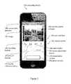
- FIG. 1illustrates a front view of a communication system embodiment.
- the communication system 200can include a security system 202 (e.g., a doorbell) and a computing device 204 .
- a security system 202e.g., a doorbell
- the security system 202can include a camera assembly 208 and a doorbell button 212 .
- the camera assembly 208can be a video camera, which in some embodiments is a webcam.
- the security system 202can include a diagnostic light 216 and a power indicator light 220 .
- the diagnostic light 216is a first color (e.g., blue) if the security system 202 and/or the communication system 200 is connected to a wireless Internet network and is a second color (e.g., red) if the security system 202 and/or the communication system 200 is not connected to a wireless Internet network.
- the power indicator 220is a first color if the security system 202 is connected to a power source. The power source can be power supplied by the building to which the security system 202 is attached. In some embodiments, the power indicator 220 is a second color or does not emit light if the security system 202 is not connected to the power source.
- the security system 202can include an outer housing 224 , which can be water resistant and/or waterproof.
- the outer housingcan be made from metal or plastic, such as molded plastic with a hardness of 60 Shore D.
- the outer housing 224is made from brushed nickel or aluminum.
- the security system 202can be electrically coupled to a power source, such as wires electrically connected to a building's electrical power system.
- the security system 202includes a battery for backup and/or primary power.
- Wireless communication 230can enable the security system 202 (e.g., a doorbell) to communicate with the computing device 204 . Some embodiments enable communication via cellular and/or Wi-Fi networks. Some embodiments enable communication via the Internet. Several embodiments enable wired communication between the security system 202 and the computing device 204 .
- the wireless communication 230can include the following communication means: radio, Wi-Fi (e.g., wireless local area network), cellular, Internet, Bluetooth, telecommunication, electromagnetic, infrared, light, sonic, and microwave. Other communication means are used by some embodiments.
- the security system 202can initiate voice calls or send text messages to a computing device 204 (e.g., a smartphone, a desktop computer, a tablet computer, a laptop computer).
- a computing device 204e.g., a smartphone, a desktop computer, a tablet computer, a laptop computer.
- Some embodimentsinclude computer software (e.g., application software), which can be a mobile application designed to run on smartphones, tablet computers, and other mobile devices. Software of this nature is sometimes referred to as “app” software. Some embodiments include software designed to run on desktop computers and laptop computers.
- the computing device 204can run software with a graphical user interface.
- the user interfacecan include icons or buttons.
- the softwareis configured for use with a touch-screen computing device such as a smartphone or tablet.
- FIG. 2illustrates a computing device 204 running software.
- the softwareincludes a user interface 240 displayed on a display screen 242 .
- the user interface 240can include a security system indicator 244 , which can indicate the location of the security system that the user interface is displaying. For example, a person can use one computing device 204 to control and/or interact with multiple security systems, such as one security system located at a front door and another security system located at a back door. Selecting the security system indicator 244 can allow the user to choose another security system (e.g., the back door security system rather than the front door security system).
- another security systeme.g., the back door security system rather than the front door security system.
- the user interface 240can include a connectivity indicator 248 .
- the connectivity indicatorcan indicate whether the computing device is in communication with a security system, the Internet, and/or a cellular network.
- the connectivity indicator 248can alert the user if the computing device 204 has lost its connection with the security system 202 ; the security system 202 has been damaged; the security system 202 has been stolen; the security system 202 has been removed from its mounting location; the security system 202 lost electrical power; and/or if the computing device 204 cannot communicate with the security system 202 .
- the connectivity indicator 248alerts the user of the computing device 204 by flashing, emitting a sound, displaying a message, and/or displaying a symbol.
- a remote server 206sends an alert (e.g., phone call, text message, image on the user interface 240 ) regarding the power and/or connectivity issue.
- the remote server 206can manage communication between the security system 202 and the computing device.
- information from the security system 202is stored by the remote server 206 .
- information from the security system 202is stored by the remote server 206 until the information can be sent to the computing device 204 , uploaded to the computing device 204 , and/or displayed to the remotely located person via the computing device 204 .
- the remote server 206can be a computing device that stores information from the security system 202 and/or from the computing device 204 .
- the remote server 206is located in a data center.
- the computing device 204 and/or the remote server 206attempts to communicate with the security system 202 . If the computing device 204 and/or the remote server 206 is unable to communicate with the security system 202 , the computing device 204 and/or the remote server 206 alerts the remotely located person via the software, phone, text, a displayed message, and/or a website. In some embodiments, the computing device 204 and/or the remote server 206 attempts to communicate with the security system 202 periodically; at least every five hours and/or less than every 10 minutes; at least every 24 hours and/or less than every 60 minutes; or at least every hour and/or less than every second.
- the server 206can initiate communication to the computer device 204 and/or to the security system 202 . In several embodiments, the server 206 can initiate, control, and/or block communication between the computing device 204 and the security system 202 .
- a usercan log into an “app,” website, and/or software on a computing device (e.g., mobile computing device, smartphone, tablet, desktop computer) to adjust the security system settings discussed herein.
- a computing devicee.g., mobile computing device, smartphone, tablet, desktop computer
- a computing devicecan enable a user to watch live video and/or hear live audio from a security system due to the user's request rather than due to actions of a visitor.
- Some embodimentsinclude a computing device initiating a live video feed (or a video feed that is less than five minutes old).
- the user interface 240displays an image 252 such as a still image or a video of an area near and/or in front of the security system 202 .
- the image 252can be taken by the camera assembly 208 and stored by the security system 202 , server 206 , and/or computing device 204 .
- the user interface 240can include a recording button 256 to enable a user to record images, videos, and/or sound from the camera assembly 208 , microphone of the security system 202 , and/or microphone of the computing device 204 .
- the user interface 240includes a picture button 260 to allow the user to take still pictures and/or videos of the area near and/or in front of the security system 202 .
- the user interface 240can also include a sound adjustment button 264 and a mute button 268 .
- the user interface 240can include camera manipulation buttons such as zoom, pan, and light adjustment buttons.
- the camera assembly 208automatically adjusts between Day Mode and Night Mode.
- Some embodimentsinclude an infrared camera and/or infrared lights to illuminate an area near the security system 202 to enable the camera assembly 208 to provide sufficient visibility (even at night).
- buttonsinclude diverse means of selecting various options, features, and functions. Buttons can be selected by mouse clicks, keyboard commands, and touching a touch screen. Many embodiments include buttons that can be selected without touch screens.
- the user interface 240includes a quality selection button, which can allow a user to select the quality and/or amount of the data transmitted from the security system 202 to the computing device 204 and/or from the computing device 204 to the security system 202 .
- videocan be sent to and/or received from the computing device 204 using video chat protocols such as FaceTime (by Apple Inc.) or Skype (by Microsoft Corporation).
- videochat protocolssuch as FaceTime (by Apple Inc.) or Skype (by Microsoft Corporation).
- these videosare played by videoconferencing apps on the computing device 204 instead of being played by the user interface 240 .
- the user interface 240can include a termination button 276 to end communication between the security system 202 and the computing device 204 .
- the termination button 276ends the ability of the person located near the security system 202 (i.e., the visitor) to hear and/or see the user of the computing device 204 , but does not end the ability of the user of the computing device 204 to hear and/or see the person located near the security system 202 .
- a button 276is both an answer button (to accept a communication request from a visitor) and is a termination button (to end communication between the security system 202 and the computing device 204 ).
- the button 276can include the word “Answer” when the system is attempting to establish two-way communication between the visitor and the user. Selecting the button 276 when the system is attempting to establish two-way communication between the visitor and the user can start two-way communication.
- the button 276can include the words “End Call” during two-way communication between the visitor and the user. Selecting the button 276 during two-way communication between the visitor and the user can terminate two-way communication. In some embodiments, terminating two-way communication still enables the user to see and hear the visitor. In some embodiments, terminating two-way communication causes the computing device 204 to stop showing video from the security system and to stop emitting sounds recorded by the security system.
- the user interface 240opens as soon as the security system detects a visitor (e.g., senses indications of a visitor). Once the user interface 240 opens, the user can see and/or hear the visitor even before “answering” or otherwise accepting two-way communication, in several embodiments.
- Some method embodimentsinclude detecting a visitor with a security system.
- the methodscan include causing the user interface to display on a remote computing device 204 due to the detection of the visitor (e.g., with or without user interaction).
- the methodscan include displaying video from the security system and/or audio from the security system before the user accepts two-way communication with the visitor.
- the methodscan include displaying video from the security system and/or audio from the security system before the user accepts the visitor's communication request.
- the methodscan include the computing device simultaneously asking the user if the user wants to accept (e.g., answer) the communication request and displaying audio and/or video of the visitor. For example, in some embodiments, the user can see and hear the visitor via the security system before opening a means of two-way communication with the visitor.
- the softwareincludes means to start the video feed on demand.
- a user of the computing devicemight wonder what is happening near the security system 202 .
- the usercan open the software application on the computing device 204 and instruct the application to show live video and/or audio from the security device 202 even if no event near the security system 202 has triggered the communication.
- the security device 202can be configured to record when the security device 202 detects movement and/or the presence of a person.
- the user of the computing device 204can later review all video and/or audio records when the security device 202 detected movement and/or the presence of a person.
- the server 206controls communication between the computing device 204 and the security system 202 , which can be a doorbell with a camera, a microphone, and a speaker. In several embodiments, the server 206 does not control communication between the computing device 204 and the security system 202 .
- data captured by the security system and/or the computing device 204is stored by another remote device such as the server 206 .
- Cloud storage, enterprise storage, and/or networked enterprise storagecan be used to store video, pictures, and/or audio from the communication system 200 or from any part of the communication system 200 .
- the usercan download and/or stream stored data and/or storage video, pictures, and/or audio. For example, a user can record visitors for a year and then later can review conversations with visitors from the last year.
- remote storage, the server 206 , the computing device 204 , and/or the security system 202can store information and statistics regarding visitors and usage.
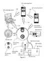
- FIG. 3illustrates an embodiment in which a security system 202 is connected to a building 300 , which can include an entryway 310 that has a door 254 .
- a door lock 250can be configured to lock and unlock the door 254 .
- Electrical wires 304can electrically couple the security system 202 to the electrical system of the building 300 so that the security system 202 can receive electrical power from the building 300 .
- a wireless network 308can allow devices to wirelessly access the Internet.
- the security system 202can access the Internet via the wireless network 308 .
- the wireless network 308can transmit data from the security system 202 to the Internet, which can transmit the data to remotely located computing devices 204 .
- the Internet and wireless networkscan transmit data from remotely located computing devices 204 to the security system 202 .
- a security system 202connects to a home's Wi-Fi.
- one computing device 204can communicate with multiple security systems 202 .
- multiple computing devices 204can communicate with one security system 202 .
- the security system 202can communicate (e.g., wirelessly 230 ) with a television 306 , which can be a smart television. Users can view the television 306 to see a visitor and/or talk with the visitor.
- FIGS. 4-12illustrate several embodiments of doorbell systems that include electronic switch assemblies for blocking and/or allowing electricity to enter an electronic chime 412 (e.g. a digital chime).
- the doorbell system 400includes a security system 202 (e.g. electronic doorbell) that comprises a camera and a button.
- the cameramay be configurable to visually detect a visitor.
- the buttonmay be configurable to enable the visitor to sound an electronic chime 412 .
- the electronic chime 412may comprise a speaker configurable to emit a notification sound 430 in response to the visitor pressing the button of the security system 202
- the doorbell system 400may also include an electronic switch assembly 410 electrically coupled to the security system 202 and a transformer 424 .
- the electronic chime 412may be electrically coupled to the electronic switch assembly 410 .
- the electronic chime 412may also be mechanically coupled to the electronic switch assembly 410 .
- the electronic switch assembly 410also may be referred to as a printed circuit board.
- the printed circuit boardmay be configured to enable the electronic chime 412 to emit the notification sound 430 from the speaker based on digital music data.
- the electronic switch assembly 410may define a first state and a second state.
- the first statemay occur in response to a first electricity 450 that is less than a first threshold.
- the electronic switch assembly 410may block the first electricity 450 from passing through the electronic chime 412 so the electronic chime 412 does not emit the notification sound 430 .
- the printed circuit boardmay be configured to block the first electricity 450 that is less than the first threshold from entering the electronic chime 412 .
- the electronic switch assembly 410may allow the first electricity 450 to pass through the electronic switch assembly 410 from the security system 202 through the electronic switch assembly 410 to the transformer 424 , without entering the electronic chime 412 .
- the first thresholdmay be the amount of electricity required to activate the electronic chime 412 to emit the notification sound 430 .
- the second statemay occur in response to a second electricity 452 that is greater than the first threshold.
- the electronic switch assembly 410may allow the second electricity 452 to pass through the electronic chime 412 so that the electronic chime 412 emits the notification sound 430 .
- the electronic switch assembly 410or printed circuit board, may be configured to allow the second electricity 452 that is greater than the first threshold to enter the electronic chime 412 .
- the second electricity 452may cause the electronic chime 412 to emit the notification sound 430 .
- the switch assembly 410can be placed inside of a housing 415 , which can also contain the electronic chime 412 .
- the switch assembly 410 and the electronic chime 412can be mechanically coupled to the housing 415 .
- the housing 415can be a plastic housing with a hollow internal portion that contains the electronic chime 412 and the switch assembly 410 . At least one screw can mechanically couple the switch assembly inside of the housing 415 .
- the electronic doorbell(e.g., the security system 202 ) can be located outside of the housing 415 .
- the electronic doorbellis placed outside of a building 300 (shown in FIG. 3 ) while the housing 415 is placed inside of the building 300 .
- the electronic doorbell and the housing 415can be coupled to walls of the building 300 .
- the electronic doorbellcan be in a remote location relative to the housing 415 (e.g., the doorbell is located outside while the plastic housing 415 is located inside of the building).
- the doorbell, the electronic chime 412 , and the switch assembly 410can all be configured to be electrically coupled to the same building power supply 420 even when the doorbell is located in the remote location relative to the housing 415 .
- the electronic switch assembly 410may comprise a first electronic switch 414 a and a second electronic switch 416 a that is electrically coupled to the first electronic switch 414 a .
- the first and second switches 414 a and 416 amay perform different functions in response to receiving the first electricity 450 a or the second electricity 452 a .
- the first electronic switch 414 ain response to the first electricity 450 a , may allow the first electricity 450 a to flow through the electronic switch assembly 410 a and may not allow the first electricity 450 a to flow through the electronic chime 412 .
- the second electronic switch 416 adoes not allow the first electricity 450 a to flow through the electronic chime 412 . Furthermore, as illustrated in FIG. 9 , in response to the second electricity 452 a , the first and second electronic switches 414 a and 416 a allow the second electricity 452 a to flow through the electronic chime 412 .
- the first and second switches 414 a and 416 amay be configured to implement different operations based on their respective positions. For example, as illustrated in FIG. 8 , when the first electronic switch 414 a is in a first position, the first electronic switch 414 a may electrically connect the transformer 424 and the security system 202 . Likewise, as illustrated in FIG. 9 , when the first electronic switch 414 a is in a second position, the first electronic switch 414 a may electrically connect the transformer 424 and the electronic chime 412 .
- the locations of the first and second switches 414 a and 416 amay be reversed, as such, when the first electronic switch 414 a is in the second position, the first electronic switch 414 a may electrically connect the electronic chime 412 and the security system 202 .
- the first and second switches 414 a and 416 amay effectively achieve the same objective as that illustrated and described with respect to FIGS. 8 and 9 .
- the second electronic switch 416 awhen the second electronic switch 416 a is in an open position, the second electronic switch 416 a may electrically disconnect the security system 202 and the electronic chime 412 . When the second electronic switch 416 a is in the open position, the second electronic switch 416 a does not allow the first electricity 450 a to flow to the electronic chime 412 . As shown in FIG. 9 , when the second electronic switch 416 a is in a closed position, the second electronic switch 416 a may electrically connect the security system 202 and the electronic chime 412 . In this position, the second electronic switch 416 a may allow the first electricity 450 a to flow to the electronic chime 412 .
- the second electronic switch 416 awhen the second electronic switch 416 a is in the open position, the second electronic switch 416 a may electrically disconnect the transformer 424 and the electronic chime 412 . Accordingly, when the second electronic switch 416 a is in the closed position, the second electronic switch 416 a may electrically connect the transformer 424 and the electronic chime 412 .
- the position of the first and second switches 414 a and 416 amay be dependent on the position of the other switch. For example, as shown in FIG. 8 , when the first electronic switch 414 a is in the first position, the second electronic switch 416 a may be in the open position. Furthermore, as illustrated in FIG. 9 , when the first electronic switch 414 a is in the second position, the second electronic switch 416 a may be in the closed position.
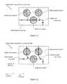
- the electronic switch assembly 410 bmay comprise a first electronic switch 414 b , a second electronic switch 416 b electrically connected to the first electronic switch 414 b , and a third electronic switch 418 b electrically connected to the first and second electronic switches 414 b and 416 b.
- the first, second and third switches 414 b , 416 b and 418 bmay move to various positions in response to receiving the first electricity 450 b or the second electricity 452 b .
- the first electronic switch 414 bin response to the first electricity 450 b , may allow the first electricity 450 b to flow through the electronic switch assembly 410 b and may not allow the first electricity 450 b to flow to the electronic chime 412 .
- the second and third electronic switches 416 b and 418 bmay not allow the first electricity 450 b to flow to the electronic chime 412 .
- FIG. 11in response to the first electricity 450 b , the first electronic switch 414 b may allow the first electricity 450 b to flow through the electronic switch assembly 410 b and may not allow the first electricity 450 b to flow to the electronic chime 412 .
- the second and third electronic switches 416 b and 418 bmay not allow the first electricity 450 b to flow to the electronic chim
- the first electronic switch 414 bmay not allow the second electricity 452 b to flow through the electronic switch assembly 410 b , and the second and third electronic switches 416 b and 418 b may allow the second electricity 452 b to flow through the electronic chime 412 .
- the first, second and third switches 414 b , 416 b and 418 bmay be configured to implement different operations based on their respective positions. For example, as illustrated in FIG. 11 , when the first electronic switch 414 b is in a closed position, the first electronic switch 414 b electrically connects the transformer 424 and the security system 202 . Likewise, as illustrated in FIG. 12 , when the first electronic switch 414 b is in an open position, the first electronic switch 414 b electrically disconnects the transformer 424 and the security system 202 .
- the second electronic switch 416 bwhen the second electronic switch 416 b is in a closed position, the second electronic switch 416 b electrically connects the transformer 424 and the electronic chime 412 .
- the second electronic switch 416 bwhen the second electronic switch 416 b is in an open position, the second electronic switch 416 b electrically disconnects the transformer 424 and the electronic chime 412 .
- the third electronic switch 418 bwhen the third electronic switch 418 b is in a closed position, the third electronic switch 418 b electrically connects the security system 202 and the electronic chime 412 . Furthermore, as shown in FIG. 11 , when the third electronic switch 418 b is in an open position, the third electronic switch 418 b electrically disconnects the security system 202 and the electronic chime 412 .
- the position of the first, second and third switches 414 b , 416 b and 418 bmay be dependent on the position of the other switches. For example, as shown in FIG. 11 , when the first electronic switch 414 b is in the closed position, the second and third electronic switches 416 b and 418 b may each be in the open position. Furthermore, as illustrated in FIG. 12 , when the first electronic switch 414 b is in the open position, the second and third electronic switches 416 b and 418 b each may be in the closed position.
- the first electronic switch 414 a and the second electronic switch 416 amay comprise any electrical component configured to route electricity or limit the amount of electricity flow, such as a resistor.
- the first electronic switch 414 amay comprise a double pole, single throw switch
- the second electronic switch 416 amay comprise a single pole, single throw switch.
- the first, second and third electronic switches 414 b , 416 b and 418 bmay each comprise a single pole, single throw switch.
- the electronic switch assembly 410may be arranged and configured in various sizes and geometries.
- the electronic switch assembly 410may comprise a base portion that defines a length that extends along a first direction and a width that extends along a second direction that is opposite the first direction.
- the electronic switch assembly 410may define a rectangular shape, wherein the length is greater than the width.
- the electronic switch assembly 410may further include three tabs 510 that may extend from the length along the second direction.
- electronic switch assembly 410 embodiments viewed from the top downmay appear to have a footprint of a capital “E.”
- the electronic switch assembly 410may be arranged and configured to define any shape.
- each of the three tabs 510may include an aperture 512 that extends through each of the three tabs 510 along a third direction that is opposite the first direction and the second direction.
- Each of the apertures 512may be configured to receive a threaded fastener.
- the electronic switch assembly 410may be mechanically coupled to the electronic chime 412 via three threaded fasteners.
- each of the threaded fastenersmay extend through a respective aperture 512 and mechanically engage the electronic chime 412 to mechanically couple the electronic switch assembly 410 to the electronic chime 412 .
- electronic switch assembly 410may include any number of apertures less than or greater than three and, accordingly, may be mechanically fastened to the electronic chime 412 via any number of mechanical fasteners, such as threaded fasteners, or the like.
- the doorbell systemcomprises a housing and the electronic chime 412 and the electronic switch assembly 410 are located inside the housing.
- the security system 202may be located outside of the housing, in a remote location relative to the housing.
- the security system 202may be located adjacent a doorway or an entry or point of a building, such as along an exterior wall adjacent a door.
- the housingis a plastic housing.
- the housingmay comprise any type of material configured to safely house electronic components inside or outside a building.
- the remote computing devicecan be configured to send and receive information to and from the security system 202 .
- the informationmay include the first threshold.
- the remote computing device 204may be used to adjust the level of the first threshold. For example, if the user wishes to adjust the first threshold from 12 volts to 14 volts, the user may do so by using the remote computing device 204 .
- the remote computing device 204may be used to change the first threshold to voltage, current, power, or the like.
- the switch assembly 410may include logic circuitry so it can be programmed according to the information as established by the remote computing device 204 .
- the informationmay include a predetermined amount of time that the second electricity is maintained above the first threshold.
- the predetermined amount of timemay determine the amount of time the electronic chime 412 emits the notification sound 430 .
- the predetermined amount of timemay be any amount of time, such as 3 seconds, 5 seconds, 10 seconds, 30 seconds, 60 seconds, or any other amount of time.
- the doorbell systemmay include an electronic doorbell, an electronic chime, and a remote computing device.
- the methodmay include obtaining the electronic doorbell (or security system 202 ) that comprises a camera and a button (at step 700 ).
- the buttonmay be configurable to enable a visitor to sound an electronic chime 412 .
- the electronic chime 412may include a speaker configurable to emit a notification sound 430 in response to the visitor pressing the button of the electronic doorbell 202 .
- the methodmay also include electrically coupling an electronic switch assembly 410 to the electronic chime 412 (at step 702 ). In several embodiments, the method also may include mechanically coupling the electronic switch assembly 410 to the electronic chime 412 .
- the methodmay include electrically coupling the electronic doorbell 202 to the electronic switch assembly 410 (at step 704 ).
- some methodsmay include configuring the electronic switch assembly 410 so that a first electricity 450 that is less than a first threshold passes through the electronic switch assembly 410 without entering the electronic chime 412 (at step 706 ). In this manner, the first electricity 450 may not cause the electronic chime 412 to emit the notification sound 430 .
- the electronic switch assembly 410may block the first electricity 450 from passing through the electronic chime 412 .
- Some embodimentsmay further include configuring the electronic switch assembly 410 so that the electronic switch assembly 410 causes a second electricity 452 that is greater than the first threshold to pass through the electronic chime 412 (at step 708 ). In this manner, the second electricity 452 may cause the electronic chime 412 to emit the notification sound 430 .
- the electronic switch assembly 410may be configured to allow the second electricity 452 to pass through the electronic chime 412 in response to the second electricity 452 being greater than the first threshold.
- the first thresholdmay be an electricity value that is required by the electronic chime 412 in order to emit the notification sound 430 .
- embodiments described in this disclosureare not limited to the first and second electricity 450 and 452 .
- several embodimentsmay further include a third and a fourth electricity.
- Some embodimentsinclude configuring an electrical circuit, such as the doorbell system 400 , so that the third electricity passes from the transformer 424 to the security system 202 , and to the electronic switch assembly 410 , and then to the transformer 424 without entering the electronic chime 412 in response to the third electricity being less than first threshold.
- several embodimentsinclude configuring the electrical circuit so that a fourth electricity passes from the transformer 424 to the security system 202 and to the electronic switch assembly 410 in response to the fourth electricity being greater than the first threshold.
- the fourth electricitymay be diverted from the electronic switch assembly 410 into the electronic chime 412 , and then back into the electronic switch assembly 410 .
- the security system 202 and the electronic switch assembly 410may be connected in series in the electrical circuit. However, it should also be appreciated that the security system 202 and the electronic switch assembly 410 may be connected in parallel.
- the electronic chime 412may comprise any type of digital device configured to emit a notification sound 430 in response to the visitor pressing the button of the security system 202 .
- the electronic chime 412may be a digital chime having a first printed circuit board.
- the methodmay further include configuring the first printed circuit board to enable the electronic chime 412 to emit the notification sound 430 from the speaker based on digital music data.
- the security system 202when the visitor presses the button of the security system 202 , the security system 202 may be configured to route all electricity to the electronic chime 412 via the electronic switch assembly 410 .
- the security system 202may further comprise a second printed circuit board.
- the methodmay further include routing at least a portion of the first electricity 450 through the second printed circuit board of the security system 202 .
- the methodmay further include blocking the second electricity 452 from entering the second printed circuit board of the security system.
- the methodmay include causing the second electricity 452 to be greater than the first threshold in response to the visitor pressing the button of the security system 202 .
- the doorbell system 400via the electronic switch assembly 410 , also may be configured to block the first electricity 450 from entering the electronic chime 412 when the first electricity 450 is less than the first threshold.
- the methodmay include using the electronic switch assembly 410 to block transformer electrical power from entering the electronic chime 412 while the first electricity 450 is less than the first threshold.
- the methodmay include using the electronic switch assembly 410 to divert the transformer electrical power from the electronic switch assembly 410 into the electronic chime 412 while the second electricity 452 is greater than the first threshold.
- the first thresholdmay be any type of electricity, such as power, voltage, and/or current.
- the first thresholdmay be described as a first electrical power threshold, a first electrical voltage threshold, and/or a first electrical current threshold.
- the doorbell system 400may also include the remote computing device 204 , which can be used to send and receive information to and/or from the security system 202 .
- the informationmay include a predetermined amount of time that defines the duration of time the electronic chime 412 emits the notification sound 430 .
- some embodimentsmay further include setting the predetermined amount of time via the remote computing device 204 prior to the second electricity 452 exceeding the first threshold.
- the methodmay include sending the predetermined amount of time wirelessly from the remote computing device 204 to the security system 202 . And once the second electricity 452 is greater than the first threshold, the method may further include maintaining the second electricity 452 above the first threshold for the predetermined amount of time.
- the doorbell system 400comprises a housing, such as a plastic housing. Accordingly, the method may further include placing the electronic chime 412 and the electronic switch assembly 410 inside the plastic housing. As well, the method may include placing the security system 202 outside the plastic housing and in a remote location relative to the plastic housing. Some methods may further include mounting the plastic housing along an interior surface of the building and mounting the security system 202 along an exterior surface of the building near an entry point of the building. However, it should be appreciated that the plastic housing and/or the security system 202 may be mounted anywhere along an interior or exterior surface of the building.
- some embodimentsdisclose another method for using the doorbell system 400 .
- the methodmay include obtaining the security system 202 (at step 800 ).
- the methodmay also include mechanically coupling a printed circuit board 410 to the electronic chime 412 and electrically coupling the printed circuit board 410 to the electronic chime 412 (at step 802 ).
- some methodsinclude electrically coupling the security system 202 to the printed circuit board 410 (at step 804 ).
- Several embodimentsmay include configuring the printed circuit board 410 so that the printed circuit board 410 allows a first electricity 450 to pass through the printed circuit board 410 in response to the first electricity 450 being less than the first threshold (at step 806 ).
- the methodmay include configuring the printed circuit board 410 so that the printed circuit board 410 blocks the first electricity 450 from entering the electronic chime 412 in response to the first electricity 450 being less than the first threshold (at step 808 ). Accordingly, the first electricity 450 does not cause the electronic chime 412 to emit the notification sound 430 .
- Several embodimentsmay further include configuring the printed circuit board 410 so that the printed circuit board 410 causes a second electricity 452 that is greater than the first threshold to enter the electronic chime 412 to cause the electronic chime to emit the notification sound 430 .
- the printed circuit board 410may cause the second electricity 452 to pass through the electronic chime 412 in response to the second electricity 452 being greater than the first threshold.
- the printed circuit board 410may be described as a first printed circuit board, and the security system 202 may comprise a second printed circuit board. Similar to the method illustrated in FIG. 14 , the method disclosed in FIG. 15 may further include routing at least a portion of the first electricity 450 through the second printed circuit board of the security system 202 . As well, this method may further include configuring the second printed circuit board to block the second electricity 452 from entering the second printed circuit board of the security system 202 in response to the visitor pressing the button. Stated differently, these steps may allow all of the transformer electrical power to be blocked from entering the security system 202 and diverted to the electronic chime 412 so that the chime may have enough electrical power to emit the notification sound 430 .
- the methodincludes obtaining the security system 202 (at step 900 ). Similar to the methods illustrated in FIG. 14 , many embodiments also include mechanically coupling the printed circuit board 410 to the electronic chime 412 and electrically coupling the printed circuit board 410 to the electronic chime 412 (at step 902 ). As well, several embodiments include electrically coupling the security system 202 to the printed circuit board 410 (at step 904 ). With continued reference to FIG.
- many embodimentsin response to the second electricity 452 being greater than the first threshold, many embodiments also include configuring the electronic switch assembly 410 so that the electronic switch assembly 410 causes the second electricity 452 to pass through the electronic chime 412 to cause the electronic chime 412 to emit the notification sound 430 (at step 906 ).
- section headings and subheadings provided hereinare nonlimiting.
- the section headings and subheadingsdo not represent or limit the full scope of the embodiments described in the sections to which the headings and subheadings pertain.
- a section titled “Topic 1”may include embodiments that do not pertain to Topic 1 and embodiments described in other sections may apply to and be combined with embodiments described within the “Topic 1” section.
- routines, processes, methods, and algorithms described in the preceding sectionsmay be embodied in, and fully or partially automated by, code modules executed by one or more computers, computer processors, or machines configured to execute computer instructions.
- the code modulesmay be stored on any type of non-transitory computer-readable storage medium or tangible computer storage device, such as hard drives, solid state memory, flash memory, optical disc, and/or the like.
- the processes and algorithmsmay be implemented partially or wholly in application-specific circuitry.
- the results of the disclosed processes and process stepsmay be stored, persistently or otherwise, in any type of non-transitory computer storage such as, e.g., volatile or non-volatile storage.
- A, B, and/or Ccan be replaced with A, B, and C written in one sentence and A, B, or C written in another sentence.
- A, B, and/or Cmeans that some embodiments can include A and B, some embodiments can include A and C, some embodiments can include B and C, some embodiments can only include A, some embodiments can include only B, some embodiments can include only C, and some embodiments can include A, B, and C.
- the term “and/or”is used to avoid unnecessary redundancy.
Landscapes
- Engineering & Computer Science (AREA)
- Signal Processing (AREA)
- Multimedia (AREA)
- Physics & Mathematics (AREA)
- Electromagnetism (AREA)
- General Physics & Mathematics (AREA)
- Interconnected Communication Systems, Intercoms, And Interphones (AREA)
Abstract
Description
Claims (15)
Priority Applications (6)
| Application Number | Priority Date | Filing Date | Title |
|---|---|---|---|
| US15/673,896US10440165B2 (en) | 2013-07-26 | 2017-08-10 | Doorbell communication and electrical systems |
| US15/990,601US10440166B2 (en) | 2013-07-26 | 2018-05-26 | Doorbell communication and electrical systems |
| US16/557,753US10708404B2 (en) | 2014-09-01 | 2019-08-30 | Doorbell communication and electrical systems |
| US16/888,534US11140253B2 (en) | 2013-07-26 | 2020-05-29 | Doorbell communication and electrical systems |
| US17/476,372US11889009B2 (en) | 2013-07-26 | 2021-09-15 | Doorbell communication and electrical systems |
| US18/389,645US20240171667A1 (en) | 2013-07-26 | 2023-12-19 | Doorbell communication and electrical systems |
Applications Claiming Priority (12)
| Application Number | Priority Date | Filing Date | Title |
|---|---|---|---|
| US201361859070P | 2013-07-26 | 2013-07-26 | |
| US201361872439P | 2013-08-30 | 2013-08-30 | |
| US14/099,888US8823795B1 (en) | 2013-07-26 | 2013-12-06 | Doorbell communication systems and methods |
| US14/098,772US8780201B1 (en) | 2013-07-26 | 2013-12-06 | Doorbell communication systems and methods |
| US14/142,839US8842180B1 (en) | 2013-07-26 | 2013-12-28 | Doorbell communication systems and methods |
| US14/275,811US8872915B1 (en) | 2013-07-26 | 2014-05-12 | Doorbell communication systems and methods |
| US14/474,210US8953040B1 (en) | 2013-07-26 | 2014-09-01 | Doorbell communication and electrical systems |
| US14/474,209US8937659B1 (en) | 2013-07-26 | 2014-09-01 | Doorbell communication and electrical methods |
| US14/492,809US9065987B2 (en) | 2013-07-26 | 2014-09-22 | Doorbell communication systems and methods |
| US14/502,601US9094584B2 (en) | 2013-07-26 | 2014-09-30 | Doorbell communication systems and methods |
| US14/588,881US9736284B2 (en) | 2013-07-26 | 2015-01-02 | Doorbell communication and electrical systems |
| US15/673,896US10440165B2 (en) | 2013-07-26 | 2017-08-10 | Doorbell communication and electrical systems |
Related Parent Applications (2)
| Application Number | Title | Priority Date | Filing Date |
|---|---|---|---|
| US14/588,881ContinuationUS9736284B2 (en) | 2013-07-26 | 2015-01-02 | Doorbell communication and electrical systems |
| US15/008,366Continuation-In-PartUS9786133B2 (en) | 2013-12-06 | 2016-01-27 | Doorbell chime systems and methods |
Related Child Applications (1)
| Application Number | Title | Priority Date | Filing Date |
|---|---|---|---|
| US15/990,601ContinuationUS10440166B2 (en) | 2013-07-26 | 2018-05-26 | Doorbell communication and electrical systems |
Publications (2)
| Publication Number | Publication Date |
|---|---|
| US20170339262A1 US20170339262A1 (en) | 2017-11-23 |
| US10440165B2true US10440165B2 (en) | 2019-10-08 |
Family
ID=63583818
Family Applications (2)
| Application Number | Title | Priority Date | Filing Date |
|---|---|---|---|
| US15/673,896ActiveUS10440165B2 (en) | 2013-07-26 | 2017-08-10 | Doorbell communication and electrical systems |
| US15/990,601ActiveUS10440166B2 (en) | 2013-07-26 | 2018-05-26 | Doorbell communication and electrical systems |
Family Applications After (1)
| Application Number | Title | Priority Date | Filing Date |
|---|---|---|---|
| US15/990,601ActiveUS10440166B2 (en) | 2013-07-26 | 2018-05-26 | Doorbell communication and electrical systems |
Country Status (3)
| Country | Link |
|---|---|
| US (2) | US10440165B2 (en) |
| JP (1) | JP2021525979A (en) |
| WO (1) | WO2019231585A1 (en) |
Cited By (2)
| Publication number | Priority date | Publication date | Assignee | Title |
|---|---|---|---|---|
| US20230121230A1 (en)* | 2018-08-14 | 2023-04-20 | Food Service Monitoring, Inc. | Method and system for motivating and monitoring hygiene compliance in a hospital or related environment |
| US11763643B2 (en)* | 2019-06-10 | 2023-09-19 | Logitech Europe S.A. | Doorbell system with energy storage device |
Families Citing this family (16)
| Publication number | Priority date | Publication date | Assignee | Title |
|---|---|---|---|---|
| US10708404B2 (en) | 2014-09-01 | 2020-07-07 | Skybell Technologies Ip, Llc | Doorbell communication and electrical systems |
| USD824791S1 (en)* | 2017-08-15 | 2018-08-07 | SkyBell Technologies, Inc. | Doorbell chime |
| US10368040B2 (en)* | 2017-11-15 | 2019-07-30 | Google Llc | Doorbell camera with battery at chime |
| US10938294B1 (en)* | 2018-04-02 | 2021-03-02 | Amazon Technologies, Inc. | Doorbell circuit architecture |
| EP3668073B1 (en)* | 2018-12-12 | 2022-07-13 | Netatmo | Method for adapting an electrical circuit with a controlling device |
| US11869341B2 (en)* | 2019-03-15 | 2024-01-09 | Nicor, Inc. | IoT compatible electronic door chime |
| USD904217S1 (en) | 2019-09-24 | 2020-12-08 | Skybell Technologies Ip, Llc | Doorbell |
| USD955252S1 (en) | 2020-01-02 | 2022-06-21 | Skybell Technologies Ip, Llc | Doorbell chime |
| USD912123S1 (en) | 2020-01-02 | 2021-03-02 | SkyBell Technologies, Inc. | Power outlet camera |
| USD918079S1 (en) | 2020-01-02 | 2021-05-04 | Skybell Technologies Ip, Llc | Doorbell |
| USD923505S1 (en) | 2020-01-02 | 2021-06-29 | Skybell Technologies Ip, Llc | Doorbell |
| USD978701S1 (en) | 2020-01-03 | 2023-02-21 | Skybell Technologies Ip, Llc | Doorbell |
| USD924302S1 (en) | 2020-01-05 | 2021-07-06 | Skybell Technologies Ip, Llc | Camera |
| USD945298S1 (en) | 2020-03-25 | 2022-03-08 | Skybell Technologies Ip, Llc | Doorbell |
| US11743392B2 (en)* | 2020-07-17 | 2023-08-29 | Alarm.Com Incorporated | Smart electronic chime and mechanical chime dehum board |
| CN112071000B (en)* | 2020-09-09 | 2022-09-30 | 李永杰 | Intelligent security doorbell |
Citations (285)
| Publication number | Priority date | Publication date | Assignee | Title |
|---|---|---|---|---|
| US1647558A (en) | 1927-11-01 | Doorbell structure | ||
| US1647708A (en) | 1925-02-04 | 1927-11-01 | Monica Pasquale Della | Doorbell and light-control switch |
| US3240113A (en) | 1961-08-29 | 1966-03-15 | Visophone Internat Establishme | Pickup and projection mirror system for panoramic photography and panoramic picture projection at horizontal plane angles |
| US3708742A (en) | 1971-06-30 | 1973-01-02 | Ibm | High dc to low dc voltage converter |
| US4523193A (en) | 1983-11-21 | 1985-06-11 | Levinson Samuel H | Remote-controlled doorbell signal receiver |
| USD283130S (en) | 1983-11-30 | 1986-03-25 | Claiborne Electronics, Inc. | Combined door viewer and two-way intercom unit |
| USD297222S (en) | 1985-12-20 | 1988-08-16 | Rauch Howard L | Smoke and fire alarm |
| US4843461A (en) | 1985-06-25 | 1989-06-27 | Matsushita Electric Works, Ltd. | Over-door interphone system provided with a night-vision monitoring device |
| US4982092A (en) | 1973-07-05 | 1991-01-01 | The United States Of America As Represented By The Secretary Of The Navy | 360 Degree optical surveillance system |
| US5210520A (en) | 1987-07-15 | 1993-05-11 | Housley Todd B | Programmable doorbell control |
| US5428388A (en) | 1992-06-15 | 1995-06-27 | Richard von Bauer | Video doorbell system |
| EP0684743A2 (en) | 1994-05-25 | 1995-11-29 | Siemens Aktiengesellschaft | Programmable radio transceiver |
| US5493618A (en) | 1993-05-07 | 1996-02-20 | Joseph Enterprises | Method and apparatus for activating switches in response to different acoustic signals |
| US5521578A (en) | 1991-01-31 | 1996-05-28 | Delvalle; Ivan | Display and control device for homes, apartments, and other buildings |
| USD371086S (en) | 1995-04-11 | 1996-06-25 | DAC Technolgies of America, Inc. | Window alarm |
| US5602580A (en) | 1993-09-17 | 1997-02-11 | Tseng; Ling-Yuan | Video communication controller using FM sideband transmission |
| USD381638S (en) | 1995-03-07 | 1997-07-29 | Siemens Nixdorf Informationssysteme Ag | Portable multimedia terminal housing |
| US5781108A (en) | 1995-11-14 | 1998-07-14 | Future Tech Systems, Inc. | Automated detection and monitoring (ADAM) |
| US5784446A (en) | 1996-11-01 | 1998-07-21 | Cms Investors | Method and apparatus for installing telephone intercom-voice messaging apparatus at doorbell for dwelling |
| USD404673S (en) | 1998-04-30 | 1999-01-26 | Tom Gordon | Doorbell button |
| US5907352A (en) | 1997-02-20 | 1999-05-25 | Gilley; Terry W. | Door mountable security system |
| US5995139A (en) | 1995-09-25 | 1999-11-30 | Samsung Electronics., Ltd. | System for identifying visitors using CCTV camera and home computer |
| US6028626A (en) | 1995-01-03 | 2000-02-22 | Arc Incorporated | Abnormality detection and surveillance system |
| USD421727S (en) | 1999-05-11 | 2000-03-21 | Theodore Pierson | Doorbell button |
| USD422521S (en) | 1999-07-29 | 2000-04-11 | Universal Security Instruments, Inc. | Smoke detector |
| US6073192A (en) | 1994-09-07 | 2000-06-06 | Rsi Systems, Inc. | Peripheral video conferencing system with control unit that controls presentation of remote video signal through the output connector |
| US6094213A (en) | 1997-04-12 | 2000-07-25 | Samsung Electronics Co., Ltd. | Computer conference system with video phone connecting function |
| US6185294B1 (en) | 1996-11-01 | 2001-02-06 | O. Joseph Chornenky | Method and apparatus for installing telephone intercom-voice messaging apparatus at doorbell for dwelling |
| US6226031B1 (en) | 1992-02-19 | 2001-05-01 | Netergy Networks, Inc. | Video communication/monitoring apparatus and method therefor |
| US20010010555A1 (en) | 1996-06-24 | 2001-08-02 | Edward Driscoll Jr | Panoramic camera |
| US20010022627A1 (en) | 2000-03-20 | 2001-09-20 | Rainer Bernhardt | Video surveillance apparatus with a dome camera and a protective housing |
| US6313743B1 (en) | 1997-08-01 | 2001-11-06 | Siemens Aktiengellschaft | Home emergency warning system |
| WO2001093220A1 (en) | 2000-05-26 | 2001-12-06 | Royal Thoughts, L.L.C. | Modular communication and control system and method |
| US6414589B1 (en)* | 1996-07-08 | 2002-07-02 | Dimango Products Corporation | Apparatus for remotely controlling auxiliary doorbell chime from doorbell push button |
| US6429893B1 (en) | 1998-06-04 | 2002-08-06 | Alfred X. Xin | Security system |
| US20030025599A1 (en) | 2001-05-11 | 2003-02-06 | Monroe David A. | Method and apparatus for collecting, sending, archiving and retrieving motion video and still images and notification of detected events |
| US6535243B1 (en) | 1998-01-06 | 2003-03-18 | Hewlett- Packard Company | Wireless hand-held digital camera |
| US6542078B2 (en) | 1996-05-30 | 2003-04-01 | Henry J. Script | Portable motion detector and alarm system and method |
| US6590604B1 (en) | 2000-04-07 | 2003-07-08 | Polycom, Inc. | Personal videoconferencing system having distributed processing architecture |
| US20030169178A1 (en)* | 2002-02-15 | 2003-09-11 | Jensen Bradford B. | Marker lights for wireless doorbell transmitters and other devices |
| US6661340B1 (en) | 2001-04-24 | 2003-12-09 | Microstrategy Incorporated | System and method for connecting security systems to a wireless device |
| US6727811B1 (en) | 1999-06-25 | 2004-04-27 | Gregory Fendis | Monitoring system |
| US20040085205A1 (en) | 2002-10-31 | 2004-05-06 | Jacob Yeh | Monitor system with video and audio transmission actuated by doorbell actuator |
| US20040086093A1 (en) | 2002-10-29 | 2004-05-06 | Schranz Paul Steven | VoIP security monitoring & alarm system |
| US20040085449A1 (en) | 1999-12-15 | 2004-05-06 | Advanced Technology Video, Inc. | Directional motion estimator |
| US6753899B2 (en) | 2002-09-03 | 2004-06-22 | Audisoft | Method and apparatus for telepresence |
| US6778084B2 (en) | 2002-01-09 | 2004-08-17 | Chang Industry, Inc. | Interactive wireless surveillance and security system and associated method |
| US20040178889A1 (en) | 2000-12-20 | 2004-09-16 | Buckingham Duane W. | System and method for managing services and facilities in a multi-unit building |
| GB2400958A (en) | 2003-04-23 | 2004-10-27 | Frank Cunningham | Doorbell camera device |
| US6812970B1 (en) | 2000-05-15 | 2004-11-02 | Mcbride Richard L. | Video camera utilizing power line modulation |
| US20040229569A1 (en) | 2003-05-13 | 2004-11-18 | Hewlett-Packard Development Company, L.P. | Door answering systems and methods |
| US6828909B2 (en) | 1996-05-30 | 2004-12-07 | Guardit Technologies Llc | Portable motion detector and alarm system and method |
| US20040257336A1 (en) | 2003-03-05 | 2004-12-23 | Shmuel Hershkovitz | Security system user interface with video display |
| USD500751S1 (en) | 2003-12-25 | 2005-01-11 | Matsushita Electric Industrial Co., Ltd. | Outdoor intercom unit |
| US20050007451A1 (en)* | 2003-07-11 | 2005-01-13 | Chiang Thomas Shiaw-Cherng | Premises entry security system |
| US20050006528A1 (en) | 2002-09-26 | 2005-01-13 | Sami Movsesian | Integrated cockpit door lock and access system |
| USD501652S1 (en) | 2003-05-15 | 2005-02-08 | Theodore Pierson | Doorbell push button |
| US20050046584A1 (en) | 1992-05-05 | 2005-03-03 | Breed David S. | Asset system control arrangement and method |
| US20050057361A1 (en) | 2003-07-10 | 2005-03-17 | University Of Florida Research Foundation, Inc. | Remote surveillance and assisted care using a mobile communication device |
| US20050097248A1 (en) | 2003-10-29 | 2005-05-05 | Kelley Brian H. | System and method for establishing a communication between a peripheral device and a wireless device |
| US20050116480A1 (en) | 2003-03-21 | 2005-06-02 | Deng Sheng B. | Door lock and operation mechanism |
| US6928461B2 (en) | 2001-01-24 | 2005-08-09 | Raja Singh Tuli | Portable high speed internet access device with encryption |
| US6930599B2 (en) | 1999-07-20 | 2005-08-16 | @ Security Broadband Corp. | Security system |
| US20050237208A1 (en) | 2004-04-09 | 2005-10-27 | Jamie Wojcik | Motion detector and illumination apparatus and method |
| US20050267605A1 (en) | 2004-01-07 | 2005-12-01 | Lee Paul K | Home entertainment, security, surveillance, and automation control system |
| US20050285934A1 (en) | 2002-10-15 | 2005-12-29 | Ronald Carter | Automated audio video messaging and answering system |
| US20050285944A1 (en) | 2000-10-04 | 2005-12-29 | Mikio Watanabe | Recording apparatus, communications apparatus, recording system, communications system, and methods therefor |
| US20060010504A1 (en) | 2004-07-06 | 2006-01-12 | Via Telecom, Ltd. | Security apparatus using a telecommunication device |
| US20060038663A1 (en) | 2004-05-08 | 2006-02-23 | Scott Steinetz | Sampling playback doorbell system |
| US20060063517A1 (en) | 2004-09-22 | 2006-03-23 | Yeonjoo Oh | Intelligent system for identifying visitor and providing communication service using mobile terminal and method thereof |
| USD519100S1 (en) | 2005-01-13 | 2006-04-18 | Matsushita Electric Industrial Co., Ltd. | Outdoor intercom unit |
| US20060093187A1 (en) | 2004-10-12 | 2006-05-04 | Anurag Mittal | Video-based encroachment detection |
| US20060100002A1 (en) | 2003-10-15 | 2006-05-11 | Eaton Corporation | Wireless node providing improved battery power consumption and system employing the same |
| USD522490S1 (en) | 2004-07-28 | 2006-06-06 | Matsushita Electric Industrial, Co., Ltd. | Outdoor intercom unit |
| US20060139449A1 (en) | 2004-12-23 | 2006-06-29 | Wen-Liang Cheng | Wireless audio-video doorbell monitoring system |
| US20060156361A1 (en) | 2005-01-12 | 2006-07-13 | Wang Walter W | Remote viewing system |
| US20060152365A1 (en) | 2003-10-15 | 2006-07-13 | Kim Walter T | Anti-theft and security system for computers |
| USD525963S1 (en) | 2004-07-28 | 2006-08-01 | Matsushita Electric Industrial Co., Ltd. | Outdoor intercom unit |
| US7113578B2 (en) | 2002-11-12 | 2006-09-26 | Electronic Locking Specialties, Inc. | Vandal proof intercom system for apartment buildings |
| USD531160S1 (en) | 2004-07-28 | 2006-10-31 | Matsushita Electric Industrial Co., Ltd. | Outdoor intercom unit |
| US20060271678A1 (en) | 2005-05-30 | 2006-11-30 | Rambus, Inc. | Self-powered devices and methods |
| US20060273895A1 (en) | 2005-06-07 | 2006-12-07 | Rhk Technology, Inc. | Portable communication device alerting apparatus |
| US20070008081A1 (en) | 2005-06-17 | 2007-01-11 | Tylicki Scott B | MP3 doorbell chime system |
| US20070029486A1 (en) | 2005-03-21 | 2007-02-08 | Visonic Ltd. | Passive infra-red detectors |
| US20070046442A1 (en) | 2005-08-25 | 2007-03-01 | O-Zone Management Corporation | Wireless door chime having changeable high quality sounds and method therefor |
| US20070052531A1 (en)* | 2005-09-02 | 2007-03-08 | Mathews David K | Apparatus and method for converting a low voltage AC wiring circuit to a high speed data communications link |
| US20070103541A1 (en) | 2002-10-15 | 2007-05-10 | Revolutionary Concepts, Inc. | Two-way audio-video communication method for receiving person at entrance |
| US7218220B1 (en)* | 2005-02-09 | 2007-05-15 | Bovsun Vladimir V | Signaling system |
| US20070109441A1 (en) | 2005-11-15 | 2007-05-17 | Yi-Jen Cheng | Defogging device for a surveillance camera |
| US20070126574A1 (en) | 2005-12-02 | 2007-06-07 | Peter Langer | Automatic Doorbell Driver |
| US20070146122A1 (en) | 2005-12-22 | 2007-06-28 | Ratner David L | Window-attached alerting device |
| US20070146115A1 (en) | 2005-01-27 | 2007-06-28 | Roosli Philipp A | Power management lock system and method |
| US20070176778A1 (en) | 2004-03-31 | 2007-08-02 | Omron Corporation | Information processing apparatus, information processing control system, control method for information processing apparatus, control program for informaion processing apparaus recording meduim on which control program for information processing apparatus is recorded |
| US20070194945A1 (en) | 2004-12-07 | 2007-08-23 | Paul Atkinson | Mobile Device for Selectively Activating a Target and Method of Using Same |
| US20070216764A1 (en) | 2006-01-09 | 2007-09-20 | Samsung Electronics Co., Ltd. | Access authentication system and method using smart communicator |
| WO2007111802A2 (en) | 2006-03-24 | 2007-10-04 | Rsialarm, Inc. | Security monitoring with programmable mapping |
| US20070237358A1 (en) | 2006-04-11 | 2007-10-11 | Wei-Nan William Tseng | Surveillance system with dynamic recording resolution and object tracking |
| US7330649B2 (en) | 2001-11-21 | 2008-02-12 | Thales Avionics, Inc. | Universal security camera |
| US20080036862A1 (en) | 2006-08-11 | 2008-02-14 | Steve Lang | Digital video surveillance system |
| USD562306S1 (en) | 2007-03-27 | 2008-02-19 | Samsung Electronics Co., Ltd. | Door-phone for home network |
| US7375492B2 (en) | 2003-12-12 | 2008-05-20 | Microsoft Corporation | Inductively charged battery pack |
| US20080129825A1 (en) | 2006-12-04 | 2008-06-05 | Lynx System Developers, Inc. | Autonomous Systems And Methods For Still And Moving Picture Production |
| US20080128586A1 (en) | 2006-10-13 | 2008-06-05 | Johnson Richard L | Sun sensor assembly and related method of using |
| US20080136915A1 (en) | 2006-12-06 | 2008-06-12 | Sony Corporation | Wall mount camera |
| US20080157956A1 (en) | 2006-12-29 | 2008-07-03 | Nokia Corporation | Method for the monitoring of sleep using an electronic device |
| US20080167072A1 (en) | 2007-01-04 | 2008-07-10 | Viktors Berstis | System and method for providing telephone service access via a gateway telephone |
| US20080198225A1 (en) | 2006-12-07 | 2008-08-21 | Ehud Gal | TVMS- a total view monitoring system |
| USD577301S1 (en) | 2007-06-18 | 2008-09-23 | Honeywell International, Inc. | Gas detector |
| US20080297339A1 (en) | 2008-07-18 | 2008-12-04 | Mathews David K | Apparatus and Method for Converting a Low Voltage AC Wiring Circuit to a High Speed Data Communications Link |
| US7477134B2 (en) | 2006-05-06 | 2009-01-13 | Peter Langer | Apparatuses and methods for driving a doorbell system peripheral load at a higher current |
| US7492303B1 (en) | 2006-05-09 | 2009-02-17 | Personnel Protection Technologies Llc | Methods and apparatus for detecting threats using radar |
| US20090059002A1 (en) | 2007-08-29 | 2009-03-05 | Kim Kwang Baek | Method and apparatus for processing video frame |
| USD588574S1 (en) | 2008-06-11 | 2009-03-17 | Aiphone Co., Ltd. | Interphone |
| US20090093235A1 (en) | 2007-10-05 | 2009-04-09 | Colin Grealish | System and method for protecting data in wireless devices |
| US20090141939A1 (en) | 2007-11-29 | 2009-06-04 | Chambers Craig A | Systems and Methods for Analysis of Video Content, Event Notification, and Video Content Provision |
| USD595260S1 (en) | 2008-06-11 | 2009-06-30 | Aiphone Co., Ltd. | Interphone |
| US20090207249A1 (en) | 2008-02-14 | 2009-08-20 | Bulent Erel | Climate controlled surveillance system |
| US20090213208A1 (en) | 2008-02-21 | 2009-08-27 | Otto Glatt | Panoramic camera |
| US7583191B2 (en) | 2006-11-14 | 2009-09-01 | Zinser Duke W | Security system and method for use of same |
| US20090243852A1 (en) | 2007-10-23 | 2009-10-01 | La Crosse Technology, Ltd. | Remote Location Monitoring |
| US20090284578A1 (en) | 2008-05-11 | 2009-11-19 | Revolutionary Concepts, Inc. | Real estate communications and monitoring systems and methods for use by real estate agents |
| US20090296641A1 (en) | 2008-05-28 | 2009-12-03 | Maik Bienas | Wireless femtocell setup methods and apparatus |
| US20090308116A1 (en) | 2006-07-27 | 2009-12-17 | Harry Lambrou | Lock Arrangement and a Method of Providing Power to a Lock |
| US20100087161A1 (en) | 2008-10-08 | 2010-04-08 | Sony Ericsson Mobile Communications Ab | Personal security feature for a regular camera phone |
| US7701171B2 (en) | 2005-08-31 | 2010-04-20 | Pro Tech Monitoring, Inc. | System, method and apparatus for charging a worn device |
| US20100103300A1 (en) | 2008-10-24 | 2010-04-29 | Tenebraex Corporation | Systems and methods for high resolution imaging |
| US20100134072A1 (en) | 2004-09-15 | 2010-06-03 | Belkin International, Inc. | Rechargeable Battery Packs And Related Methods |
| US20100141761A1 (en) | 2008-12-08 | 2010-06-10 | Mccormack Kenneth | Method and system for stabilizing video images |
| US7738917B2 (en) | 2003-03-31 | 2010-06-15 | Vtech Telecommunications Limited | Intercom/wireless door bell for multi-handset telephone system |
| US7746223B2 (en) | 2006-12-01 | 2010-06-29 | Embarq Holdings Company, Llc | System and method for receiving security content from wireless cameras |
| US7751285B1 (en) | 2005-03-28 | 2010-07-06 | Nano Time, LLC | Customizable and wearable device with electronic images |
| US7752070B2 (en) | 2002-11-12 | 2010-07-06 | Sas Institute Inc. | Enterprise information evolution analysis system |
| US20100195810A1 (en) | 2009-02-02 | 2010-08-05 | Alarmforce Industries Inc. | Security system with two-way communication and video |
| US20100225455A1 (en)* | 2007-10-24 | 2010-09-09 | Jimmy David Claiborne | Polyphonic Doorbell Chime System |
| US20100245060A1 (en) | 2009-03-31 | 2010-09-30 | Scott Blaise Tylicki | Method and Apparatus Pertaining to Doorbell Chimes |
| US7809966B2 (en) | 2006-01-06 | 2010-10-05 | Canon Kabushiki Kaisha | Information processing apparatus having a low power consumption state and releasing the low power consumption state to perform communication, and power control method therefor |
| US7826729B2 (en) | 2007-09-17 | 2010-11-02 | Airmar Technology Corporation | Underwater camera assembly |
| US20100276570A1 (en) | 2007-12-12 | 2010-11-04 | Mark Kevin Moser | Light source tracker |
| US20110025852A1 (en) | 2009-08-03 | 2011-02-03 | NL Giken Incorporated | Monitoring System |
| US20110090085A1 (en) | 2009-10-15 | 2011-04-21 | At & T Intellectual Property I, L.P. | System and Method to Monitor a Person in a Residence |
| US20110121940A1 (en) | 2009-11-24 | 2011-05-26 | Joseph Jones | Smart Door |
| US20110156566A1 (en) | 2009-12-25 | 2011-06-30 | Fu Zhun Precision Industry (Shen Zhen) Co., Ltd. | Led lamp |
| US7991575B2 (en) | 2009-01-08 | 2011-08-02 | Trimble Navigation Limited | Method and system for measuring angles based on 360 degree images |
| US20110207509A1 (en) | 2010-02-24 | 2011-08-25 | Palm, Inc. | Apparatus and methods for providing intelligent battery management |
| US8016676B2 (en) | 2008-05-11 | 2011-09-13 | Revolutionary Concepts, Inc. | Child's car seat assembly enabling access to remote gaming applications and two-way person-to-person communications |
| US20110221582A1 (en) | 2003-07-30 | 2011-09-15 | Lear Corporation | User-Assisted Programmable Appliance Control |
| US20110260880A1 (en) | 2010-04-21 | 2011-10-27 | Lance Dean | Solar powered light and alarm system |
| US20110287718A1 (en) | 2005-06-23 | 2011-11-24 | Microsoft Corporation | Provisioning of wireless connectivity for devices using nfc |
| US20110313775A1 (en) | 2010-05-20 | 2011-12-22 | Google Inc. | Television Remote Control Data Transfer |
| US20120011559A1 (en) | 2010-07-06 | 2012-01-12 | Nokia Corporation | Method and apparatus for selecting a security policy |
| US20120027248A1 (en) | 2010-07-27 | 2012-02-02 | International Business Machines Corporation | Foreground Analysis Based on Tracking Information |
| US20120044085A1 (en) | 2010-08-19 | 2012-02-23 | World Enterpise Sino Ltd | Multifunctional doorbell with controllable lighting |
| US20120044050A1 (en) | 2010-08-23 | 2012-02-23 | Samir Vig | Smart Doorbell Security System and Method to Identify Visitors |
| US20120044049A1 (en) | 2010-08-23 | 2012-02-23 | Samir Vig | Smart Doorbell Security System and Method to Identify Visitors |
| US8125329B1 (en) | 2005-10-12 | 2012-02-28 | Hirou Timothy L | Identification system |
| US8139098B2 (en) | 2002-10-15 | 2012-03-20 | Revolutionary Concepts, Inc. | Video communication method for receiving person at entrance |
| US8144184B2 (en) | 2002-10-15 | 2012-03-27 | Revolutionary Concepts, Inc. | Detection and viewing system |
| US20120085824A1 (en) | 2010-10-08 | 2012-04-12 | Symbol Technologies, Inc. | Object proximity sensor recessed into imaging reader |
| US20120098439A1 (en) | 2007-03-27 | 2012-04-26 | Wireless Environment, Llc | Coordinated System of Battery Powered Wireless Lights |
| US20120105631A1 (en) | 2008-10-13 | 2012-05-03 | Withings | Method and Device for Tele-Viewing |
| US20120108215A1 (en) | 2010-10-29 | 2012-05-03 | Nader Kameli | Remote notification device |
| US20120113253A1 (en) | 2010-11-08 | 2012-05-10 | Terry Slater | Residential Video Surveillance Device |
| US20120127308A1 (en) | 2010-10-14 | 2012-05-24 | Xerox Corporation | Computer-Implemented System And Method For Providing Gun Shot Detection Through A Centralized Parking Services Server |
| USD660819S1 (en) | 2012-01-04 | 2012-05-29 | Amroad Technology Inc. | Door intercom |
| US8193919B2 (en) | 2007-05-05 | 2012-06-05 | Peter Langer | Apparatuses and methods for driving a doorbell system peripheral load at a higher current |
| US20120162416A1 (en) | 2010-12-22 | 2012-06-28 | Pelco, Inc. | Stopped object detection |
| US8224311B2 (en) | 2002-07-23 | 2012-07-17 | At&T Intellectual Property I, L.P. | System and method for updating data in remote devices |
| US20120230696A1 (en) | 2000-11-15 | 2012-09-13 | Federal Law Enforcement Development Services, Inc. | Led light communication system |
| US20120230203A1 (en) | 2008-12-23 | 2012-09-13 | Centurylink Intellectual Property Llc | Network User Usage Profiling |
| US20120229282A1 (en) | 2011-03-10 | 2012-09-13 | Security Identification Systems Corporation a Florida | Maritime Overboard Detection and Tracking System |
| US20120267962A1 (en) | 2009-05-15 | 2012-10-25 | Hanchett Jr Leland J | System for Providing Power and Data Transmission Between a Door and a Frame |
| US20120280789A1 (en) | 2011-05-02 | 2012-11-08 | Apigy Inc. | Systems and methods for controlling a locking mechanism using a portable electronic device |
| US20120287123A1 (en) | 2011-05-11 | 2012-11-15 | Google Inc. | Point-of-View Object Selection |
| US8334656B2 (en) | 2009-11-03 | 2012-12-18 | Msi, Llc | Replaceable lighting unit with adjustable output intensity and optional capability for reporting usage information, and method of operating same |
| US20120320150A1 (en) | 2011-06-15 | 2012-12-20 | Montgomery Myles | Multi-lens, 360-degree time lapse camera |
| US20120327225A1 (en) | 2011-06-22 | 2012-12-27 | Barley Christopher B | Surveillance camera with wireless communication and control capability |
| US20120327246A1 (en) | 2005-03-07 | 2012-12-27 | International Business Machines Corporation | Automatic Multiscale Image Acquisition from a Steerable Camera |
| US8354914B2 (en) | 2005-01-27 | 2013-01-15 | Inncom International, Inc. | Reduced power electronic lock system |
| US20130020875A1 (en) | 2010-06-30 | 2013-01-24 | Wozniak John A | Battery pack for an electronic device |
| US20130039499A1 (en) | 2007-08-03 | 2013-02-14 | Jean-Marc G. Patenaude | Emergency notification device and system |
| US20130045763A1 (en) | 2011-04-28 | 2013-02-21 | Cellnock Corporation | System and method for providing notice of visitor |
| US20130057695A1 (en) | 2011-09-07 | 2013-03-07 | Timothy J. Huisking | Method and apparatus for unlocking/locking a door and enabling two-way communications with a door security system via a smart phone |
| CN202872976U (en) | 2012-09-21 | 2013-04-10 | 天津市滨海新区塘沽海天科贸有限公司 | Electronic doorbell based on GPRS network |
| US20130091213A1 (en) | 2011-10-08 | 2013-04-11 | Broadcom Corporation | Management of social device interaction with social network infrastructure |
| US20130094444A1 (en) | 2011-10-13 | 2013-04-18 | Applied Communications Sciences | Automatic provisioning of an m2m device having a wifi interface |
| CN202939738U (en) | 2012-09-26 | 2013-05-15 | 孙华 | Novel remote monitoring doorbell |
| US20130130749A1 (en) | 2011-09-02 | 2013-05-23 | Gn Netcom A/S | Battery Powered Electronic Device Comprising A Movable Part and Adapted to Be Set Into Shipping Mode |
| US20130128050A1 (en) | 2011-11-22 | 2013-05-23 | Farzin Aghdasi | Geographic map based control |
| US20130136033A1 (en) | 2011-11-28 | 2013-05-30 | Abhishek Patil | One-click connect/disconnect feature for wireless devices forming a mesh network |
| US20130147616A1 (en) | 2011-12-13 | 2013-06-13 | General Motors Llc | Entryway control and monitoring system |
| US20130147964A1 (en) | 2007-11-28 | 2013-06-13 | Flir Systems, Inc. | Infrared camera systems and methods for maritime applications |
| US20130169814A1 (en) | 2011-12-28 | 2013-07-04 | Da-Ming Liu | Lamp socket type camera |
| US20130169809A1 (en) | 2011-08-05 | 2013-07-04 | Marine and Remote Sensing Solutions Ltd. | Monitoring system, monitoring module apparatus and method of monitoring a volume |
| US20130173477A1 (en) | 2011-08-19 | 2013-07-04 | Geoffrey I. Cairns | Storing and forwarding credentials securely from one RFID device to another |
| US8504103B2 (en) | 2007-08-09 | 2013-08-06 | Dale Ficquette | Cellular home security system |
| US20130208123A1 (en) | 2012-02-13 | 2013-08-15 | Honeywell International Inc. | Method and System for Collecting Evidence in a Security System |
| US20130223279A1 (en) | 2012-02-24 | 2013-08-29 | Peerapol Tinnakornsrisuphap | Sensor based configuration and control of network devices |
| US20130223833A1 (en) | 2012-02-28 | 2013-08-29 | David M. Tenenbaum | Camera pod |
| USD689828S1 (en) | 2010-10-25 | 2013-09-17 | Theodore Pierson | Doorbell button |
| US8562158B2 (en) | 2004-07-06 | 2013-10-22 | Tseng-Lu Chien | Device having built-in digital data device for LED bulb |
| US8565399B2 (en) | 2005-10-20 | 2013-10-22 | NobelBiz, Inc. | System and method for modifying communication information (MCI) |
| USD692847S1 (en) | 2011-04-18 | 2013-11-05 | WGI Innovations Ltd. | Mobile wireless sound monitor base |
| US20130293722A1 (en) | 2012-05-07 | 2013-11-07 | Chia Ming Chen | Light control systems and methods |
| US20140009609A1 (en) | 2012-07-06 | 2014-01-09 | Conexant Systems, Inc. | Video door monitor using smarttv with voice wakeup |
| US20140015967A1 (en) | 2012-07-16 | 2014-01-16 | Shaun Moore | Social intelligence, tracking and monitoring system and methods |
| US8669876B2 (en) | 2008-06-05 | 2014-03-11 | 1998 David B. and Ann E. Anderson Revocable Trust | Above-water monitoring of swimming pools |
| US20140070922A1 (en) | 2012-09-10 | 2014-03-13 | Garry Davis | Doorbell system, apparatus, and method |
| US20140077929A1 (en) | 2012-03-08 | 2014-03-20 | Unikey Technologies, Inc. | Wireless access control system and related methods |
| US20140088761A1 (en) | 2012-09-21 | 2014-03-27 | Irobot Corporation | Proximity Sensing On Mobile Robots |
| WO2014062321A1 (en) | 2012-10-17 | 2014-04-24 | Unikey Technologies, Inc. | Wireless access control system and related methods |
| US20140125754A1 (en) | 2006-03-07 | 2014-05-08 | Helen Haywood | Web portal for managing premise security |
| US20140149706A1 (en) | 2012-11-26 | 2014-05-29 | Samsung Electronics Co., Ltd. | Storage device and data transfering method thereof |
| USD707147S1 (en) | 2012-07-30 | 2014-06-17 | Amroad Technology Inc. | Doorbell |
| US20140167676A1 (en) | 2011-06-06 | 2014-06-19 | Robert Bosch Gmbh | Battery pack having a separate power supply device for a wireless communication device of the battery pack |
| WO2014107196A1 (en) | 2013-01-04 | 2014-07-10 | Unikey Technologies, Inc. | Wireless access control system and related methods |
| US8780201B1 (en) | 2013-07-26 | 2014-07-15 | SkyBell Technologies, Inc. | Doorbell communication systems and methods |
| USD710728S1 (en) | 2013-06-27 | 2014-08-12 | BOT Home Automation, Inc. | Electronic device |
| USD710727S1 (en) | 2013-06-27 | 2014-08-12 | BOT Home Automation, Inc. | Electronic device |
| USD711275S1 (en) | 2013-07-26 | 2014-08-19 | SkyBell Technologies, Inc. | Doorbell |
| US20140253725A1 (en) | 2013-03-05 | 2014-09-11 | Lku Technology Ltd. | Enhanced Surveillance Camera |
| US20140267740A1 (en) | 2013-03-13 | 2014-09-18 | Kwikset Corporation | Electronic lock with remote monitoring |
| US20140267716A1 (en) | 2013-03-15 | 2014-09-18 | Vivint, Inc. | Methods for using an image capture device integrated at a building entry with an automation control panel, and systems and devices related thereto |
| US20140266669A1 (en) | 2013-03-14 | 2014-09-18 | Nest Labs, Inc. | Devices, methods, and associated information processing for security in a smart-sensored home |
| WO2014144628A2 (en) | 2013-03-15 | 2014-09-18 | Master Lock Company | Cameras and networked security systems and methods |
| US20140260449A1 (en) | 2013-03-15 | 2014-09-18 | Kwikset Corporation | Wireless lockset with integrated antenna, touch activation, and light communication method |
| US20140292194A1 (en) | 2012-01-06 | 2014-10-02 | Thermal Solution Resources, Llc | LED Lamps with Enhanced Wireless Communication |
| US20140292481A1 (en) | 2011-03-17 | 2014-10-02 | Unikey Technologies, Inc. | Wireless access control system and related methods |
| US8872915B1 (en) | 2013-07-26 | 2014-10-28 | SkyBell Technologies, Inc. | Doorbell communication systems and methods |
| US20140368643A1 (en) | 2013-06-12 | 2014-12-18 | Prevvio IP Holding LLC | Systems and methods for monitoring and tracking emergency events within a defined area |
| US8937659B1 (en) | 2013-07-26 | 2015-01-20 | SkyBell Technologies, Inc. | Doorbell communication and electrical methods |
| US20150022618A1 (en) | 2013-07-18 | 2015-01-22 | Bot Home Automation Inc. | Wireless Entrance Communication Device |
| US20150022620A1 (en) | 2013-07-18 | 2015-01-22 | Bot Home Automation Inc. | Wireless Entrance Communication Device |
| US8941736B1 (en) | 2013-07-26 | 2015-01-27 | SkyBell Technologies, Inc. | Doorbell communication systems and methods |
| US20150029335A1 (en) | 2013-07-26 | 2015-01-29 | SkyBell Technologies, Inc. | Doorbell communication systems and methods |
| US8947530B1 (en) | 2013-07-26 | 2015-02-03 | Joseph Frank Scalisi | Smart lock systems and methods |
| US8953040B1 (en) | 2013-07-26 | 2015-02-10 | SkyBell Technologies, Inc. | Doorbell communication and electrical systems |
| US20150049191A1 (en) | 2013-07-26 | 2015-02-19 | SkyBell Technologies, Inc. | Doorbell communication systems and methods |
| WO2015023737A1 (en) | 2013-08-15 | 2015-02-19 | Unikey Technologies, Inc. | Wireless access control system and related methods |
| US20150054949A1 (en) | 2013-07-26 | 2015-02-26 | SkyBell Technologies, Inc. | Doorbell communication systems and methods |
| US20150061859A1 (en) | 2013-03-14 | 2015-03-05 | Google Inc. | Security scoring in a smart-sensored home |
| US20150063559A1 (en) | 2013-08-27 | 2015-03-05 | James Siminoff | System and Method for Controlling Calls for Contact Centers |
| US20150070495A1 (en) | 2013-07-26 | 2015-03-12 | SkyBell Technologies, Inc. | Doorbell security and safety |
| US20150092055A1 (en) | 2013-07-26 | 2015-04-02 | SkyBell Technologies, Inc. | Pool monitor systems and methods |
| US20150145991A1 (en) | 2013-11-22 | 2015-05-28 | Vose Technical Systems, Inc. | System and method for shared surveillance |
| US20150156031A1 (en) | 2012-09-21 | 2015-06-04 | Google Inc. | Environmental sensing with a doorbell at a smart-home |
| US9053622B2 (en) | 2013-07-26 | 2015-06-09 | Joseph Frank Scalisi | Light socket cameras |
| US20150161856A1 (en) | 2013-12-09 | 2015-06-11 | Echostar Technologies L.L.C. | Systems and methods for home automation integration with a doorbell |
| US20150163463A1 (en) | 2013-12-06 | 2015-06-11 | Vivint, Inc. | Systems and methods for operating a doorbell camera |
| US9060104B2 (en) | 2013-07-26 | 2015-06-16 | SkyBell Technologies, Inc. | Doorbell communication systems and methods |
| US9058738B1 (en) | 2013-07-26 | 2015-06-16 | SkyBell Technologies, Inc. | Doorbell communication systems and methods |
| US9057210B2 (en) | 2011-03-17 | 2015-06-16 | Unikey Technologies, Inc. | Wireless access control system and related methods |
| US20150194839A1 (en) | 2014-01-06 | 2015-07-09 | Otter Products, Llc | Rechargeable battery pack |
| US20150276266A1 (en) | 2014-03-28 | 2015-10-01 | Google Inc. | Facilitating radio frequency communications among environmental control system components |
| US9172922B1 (en) | 2013-12-06 | 2015-10-27 | SkyBell Technologies, Inc. | Doorbell communication systems and methods |
| US20150310381A1 (en) | 2014-04-29 | 2015-10-29 | Vivint, Inc. | Systems and methods for secure package delivery |
| WO2016032217A1 (en) | 2014-08-27 | 2016-03-03 | 주식회사 토브넷 | Surveillance system |
| US9282665B1 (en) | 2014-01-13 | 2016-03-08 | Litex Industries, Limited | Illuminated doorbell chime system |
| US9336637B2 (en) | 2011-03-17 | 2016-05-10 | Unikey Technologies Inc. | Wireless access control system and related methods |
| US20160171435A1 (en) | 2014-12-12 | 2016-06-16 | At&T Intellectual Property I, L.P. | Method and apparatus for providing secure delivery |
| US20160191864A1 (en) | 2013-07-18 | 2016-06-30 | BOT Home Automation, Inc. | Wireless entrance communication device |
| US20160219254A1 (en) | 2015-01-27 | 2016-07-28 | Sercomm Corporation | Doorbell device and method thereof |
| US20160330403A1 (en) | 2015-05-07 | 2016-11-10 | BOT Home Automation, Inc. | Wireless audio/video recording and communication doorbells with integrated image sensor/button |
| US20160366373A1 (en) | 2013-07-17 | 2016-12-15 | BOT Home Automation, Inc. | Wireless speaker devices for wireless audio/video recording and communication devices |
| USD788061S1 (en) | 2014-07-18 | 2017-05-30 | BOT Home Automation, Inc. | Wireless entrance communication device |
| US20170162225A1 (en) | 2015-12-04 | 2017-06-08 | BOT Home Automation, Inc. | Motion detection for a/v recording and communication devices |
| US20170163944A1 (en) | 2015-12-04 | 2017-06-08 | BOT Home Automation, Inc. | Motion detection for a/v recording and communication devices |
| USD789404S1 (en) | 2016-01-20 | 2017-06-13 | BOT Home Automation, Inc. | Display screen or portion thereof with animated graphical user interface |
| USD789820S1 (en) | 2016-03-15 | 2017-06-20 | BOT Home Automation, Inc. | Doorbell |
| US9697723B1 (en)* | 2014-01-15 | 2017-07-04 | Litex Industries, Limited | Illuminated doorbell touch pad system |
| USD791243S1 (en) | 2016-05-26 | 2017-07-04 | BOT Home Automation, Inc. | Illuminated sign |
| USD791241S1 (en) | 2016-05-05 | 2017-07-04 | BOT Home Automation, Inc. | Illuminated sign |
| USD791240S1 (en) | 2016-05-05 | 2017-07-04 | BOT Home Automation, Inc. | Illuminated sign |
| USD791165S1 (en) | 2016-01-20 | 2017-07-04 | BOT Home Automation, Inc. | Display screen or portion thereof with animated graphical user interface |
| USD791878S1 (en) | 2016-05-26 | 2017-07-11 | BOT Home Automation, Inc. | Illuminated sign |
| US9734675B2 (en) | 2013-07-17 | 2017-08-15 | BOT Home Automation, Inc. | Wireless communication USB dongle |
| US20170251173A1 (en) | 2016-02-26 | 2017-08-31 | BOT Home Automation, Inc. | Sharing Video Footage from Audio/Video Recording and Communication Devices |
| US9761092B2 (en) | 2016-02-01 | 2017-09-12 | Sercomm Corporation | Doorbell system and doorbell control device |
| US20170272706A1 (en) | 2016-03-15 | 2017-09-21 | BOT Home Automation, Inc. | Audio/Video Recording and Communication Devices |
| USD798177S1 (en) | 2016-09-14 | 2017-09-26 | Ring Inc. | Audio/Video doorbell |
| US20170280565A1 (en) | 2016-03-24 | 2017-09-28 | BOT Home Automation, Inc. | Jumpers for pcb design and assembly |
| US20170280112A1 (en) | 2016-02-26 | 2017-09-28 | BOT Home Automation, Inc. | Providing Status Information for Secondary Devices with Video Footage from Audio/Video Recording and Communication Devices |
| US20170293883A1 (en) | 2016-04-08 | 2017-10-12 | Jianhua Li | Package Security Device |
| US20170294694A1 (en) | 2016-04-07 | 2017-10-12 | BOT Home Automation, Inc. | Combination heatsink and battery heater for electronic devices |
| US20180019889A1 (en) | 2016-07-12 | 2018-01-18 | Google Inc. | Methods and Devices for Presenting Video Feeds in a User Interface |
| US9978260B2 (en) | 2012-12-18 | 2018-05-22 | Samsung Electronics Co., Ltd. | Method and apparatus for controlling a home device remotely in a home network system |
Family Cites Families (73)
| Publication number | Priority date | Publication date | Assignee | Title |
|---|---|---|---|---|
| US3224311A (en) | 1960-02-16 | 1965-12-21 | Philip Morris Inc | Sheet subdividing apparatus |
| DE4129402A1 (en) | 1991-09-04 | 1993-03-11 | Blohm Maschinenbau Gmbh | COOLING DEVICE FOR A GRINDING MACHINE |
| JP3865516B2 (en) | 1998-10-23 | 2007-01-10 | ソニー株式会社 | Omni-directional imaging device |
| US8073327B2 (en) | 2000-11-08 | 2011-12-06 | Yaron Mayer | System and method for improving the efficiency of routers on the internet and/or cellular networks and/or other networks and alleviating bottlenecks and overloads on the network |
| US7139716B1 (en) | 2002-08-09 | 2006-11-21 | Neil Gaziz | Electronic automation system |
| US7632004B2 (en) | 2004-07-06 | 2009-12-15 | Tseng-Lu Chien | LED night light with more than 1 optics means |
| US9581299B2 (en) | 2004-07-06 | 2017-02-28 | Tseng-Lu Chien | LED bulb has multiple features |
| US7532709B2 (en) | 2005-02-04 | 2009-05-12 | Styers Justin R | Remote garage door monitoring system |
| KR100735233B1 (en) | 2005-02-25 | 2007-07-03 | 삼성전자주식회사 | Personal Broadcasting Service Provision System |
| FR2886740B1 (en)* | 2005-06-03 | 2007-09-28 | Inst Francais Du Petrole | METHOD FOR UPDATING A GEOLOGICAL MODEL WITH SEISMIC AND PRODUCTION DATA |
| CN101305350A (en) | 2005-06-09 | 2008-11-12 | 惠而浦公司 | Software architecture system and method for communicating with and managing at least one component within a household appliance |
| US20070014612A1 (en)* | 2005-07-18 | 2007-01-18 | Seong Kim | Parallel printing solution |
| US20070066316A1 (en) | 2005-09-20 | 2007-03-22 | Hoover Thomas R | Multi-channel Internet protocol smart devices |
| US9021134B1 (en) | 2006-03-03 | 2015-04-28 | Juniper Networks, Inc. | Media stream transport conversion within an intermediate network device |
| WO2007126299A1 (en) | 2006-05-02 | 2007-11-08 | Jang-Ho Park | Multi digital door |
| US8902042B2 (en) | 2006-05-16 | 2014-12-02 | Lpd, L.L.C. | Methods of controlling access to real estate properties |
| US8875208B1 (en) | 2007-11-21 | 2014-10-28 | Skype | High quality multimedia transmission from a mobile device for live and on-demand viewing |
| US7916174B2 (en) | 2007-12-18 | 2011-03-29 | Verizon Patent And Licensing Inc. | System and method for remotely controlling a camera |
| US20090273670A1 (en) | 2008-04-16 | 2009-11-05 | Christina Tamayo | Door cam security |
| EP2345017B1 (en) | 2008-10-13 | 2017-03-29 | Gentex Corporation | Communication system and method |
| USD627671S1 (en) | 2009-12-01 | 2010-11-23 | Universal Security Instruments, Inc. | DC hazardous condition detector |
| US20120293310A1 (en) | 2011-05-17 | 2012-11-22 | Heathco, Llc | Method and Apparatus Pertaining to Using a Door Chime to Audibilize Non-Door-Chime Messages |
| US20120182427A1 (en) | 2011-06-06 | 2012-07-19 | Aaron Marshall | System and method for providing thermal gender recognition |
| US9425981B2 (en) | 2011-07-14 | 2016-08-23 | Colin Foster | Remote access control to residential or office buildings |
| US8630452B2 (en) | 2011-08-02 | 2014-01-14 | Patents Innovations, Llc | Mailboxes and mailbox systems enabling enhanced security and logistics, and/or associated methods |
| US8710983B2 (en) | 2012-05-07 | 2014-04-29 | Integrated Security Corporation | Intelligent sensor network |
| US20140007092A1 (en)* | 2012-06-30 | 2014-01-02 | Microsoft Corporation | Automatic transfer of workload configuration |
| US20150035987A1 (en) | 2012-09-07 | 2015-02-05 | Jose Mario Fernandez | Method and apparatus for unlocking/locking a door and enabling two-way communications with a door security system via a smart phone |
| US9626841B2 (en) | 2012-09-21 | 2017-04-18 | Google Inc. | Occupant notification of visitor interaction with a doorbell at a smart-home |
| US9600645B2 (en) | 2012-09-21 | 2017-03-21 | Google Inc. | Smart invitation handling at a smart-home |
| US10735216B2 (en) | 2012-09-21 | 2020-08-04 | Google Llc | Handling security services visitor at a smart-home |
| US20150120015A1 (en) | 2012-09-21 | 2015-04-30 | Google Inc. | Automated handling of a package delivery at a smart-home |
| US20150120598A1 (en) | 2012-09-21 | 2015-04-30 | Google Inc. | Tracking of a package delivery to a smart-home |
| KR101545883B1 (en) | 2012-10-30 | 2015-08-20 | 삼성전자주식회사 | Method for controlling camera of terminal and terminal thereof |
| US9208629B2 (en) | 2012-10-30 | 2015-12-08 | Continental Automotive Systems, Inc. | Garage door open alert |
| US20140266702A1 (en) | 2013-03-15 | 2014-09-18 | South East Water Corporation | Safety Monitor Application |
| US9528296B1 (en) | 2013-03-15 | 2016-12-27 | August Home, Inc. | Off center drive mechanism for thumb turning lock system for intelligent door system |
| JP6089320B2 (en) | 2013-04-05 | 2017-03-08 | パナソニックIpマネジメント株式会社 | Camera device |
| WO2014179531A2 (en) | 2013-05-01 | 2014-11-06 | Nusocket Inc. | Modular illumination device and associated systems and methods |
| USD730422S1 (en) | 2013-06-17 | 2015-05-26 | Samsung Electronics Co., Ltd. | Camera |
| US9160987B1 (en) | 2013-07-26 | 2015-10-13 | SkyBell Technologies, Inc. | Doorbell chime systems and methods |
| US20150109111A1 (en) | 2013-10-23 | 2015-04-23 | The Chamberlain Group, Inc. | Wireless Door Chime |
| USD747385S1 (en) | 2013-12-06 | 2016-01-12 | SkyBell Technologies, Inc. | Video camera |
| US20150179031A1 (en) | 2013-12-19 | 2015-06-25 | Robert F. Wallace | Security device |
| US9274673B2 (en) | 2013-12-31 | 2016-03-01 | Google Inc. | Methods, systems, and media for rewinding media content based on detected audio events |
| US20150208032A1 (en) | 2014-01-17 | 2015-07-23 | James Albert Gavney, Jr. | Content data capture, display and manipulation system |
| US20150228281A1 (en) | 2014-02-07 | 2015-08-13 | First Principles,Inc. | Device, system, and method for active listening |
| US20150236966A1 (en) | 2014-02-18 | 2015-08-20 | Alcatel-Lucent Usa Inc. | Control of congestion window size of an information transmission connection |
| MX2015000104A (en) | 2014-04-01 | 2016-05-05 | Linear Llc | ACCESSORY TO OPERATE THE GARAGE DOOR. |
| US9734644B2 (en) | 2014-04-25 | 2017-08-15 | The Chamberlain Group, Inc. | Wireless camera facilitated building security |
| US10274909B2 (en) | 2014-04-25 | 2019-04-30 | Vivint, Inc. | Managing barrier and occupancy based home automation system |
| JP1525303S (en) | 2014-06-06 | 2015-06-08 | ||
| US20160019495A1 (en) | 2014-07-18 | 2016-01-21 | Dmitriy Kolchin | System and method for context-sensitive delivery notification |
| US20160057199A1 (en) | 2014-08-21 | 2016-02-25 | Facebook, Inc. | Systems and methods for transmitting a media file in multiple portions |
| US20160058181A1 (en) | 2014-09-03 | 2016-03-03 | Qing Han | Systems and Methods for Securing and Temperature Regulating a Delivery Container |
| USD748709S1 (en) | 2014-11-21 | 2016-02-02 | Lg Innotek Co., Ltd. | IP camera |
| WO2016081794A1 (en) | 2014-11-21 | 2016-05-26 | Deliveright Logistics, Inc. | Delivery management systems and methods for zero-inventory distribution |
| US10074224B2 (en) | 2015-04-20 | 2018-09-11 | Gate Labs Inc. | Access management system |
| US10635907B2 (en) | 2015-01-13 | 2020-04-28 | Vivint, Inc. | Enhanced doorbell camera interactions |
| US9833097B2 (en) | 2015-02-13 | 2017-12-05 | Cisco Technology, Inc. | Smart postal box in support of autonomous delivery nodes |
| WO2016131043A1 (en) | 2015-02-13 | 2016-08-18 | Eichenblatt David L | Systems and methods for facilitating package delivery or pickup |
| USD748179S1 (en) | 2015-02-17 | 2016-01-26 | SkyBell Technologies, Inc. | Video camera |
| USD748178S1 (en) | 2015-02-17 | 2016-01-26 | SkyBell Technologies, Inc. | Video camera |
| US9679420B2 (en) | 2015-04-01 | 2017-06-13 | Smartdrive Systems, Inc. | Vehicle event recording system and method |
| US10891584B2 (en) | 2015-04-10 | 2021-01-12 | Smiotex, Inc. | Devices, systems, and methods for storing items |
| USD776180S1 (en) | 2015-04-13 | 2017-01-10 | Fibar Group S.A. | Video gateway device |
| USD748180S1 (en) | 2015-05-28 | 2016-01-26 | SkyBell Technologies, Inc. | Video camera |
| USD803923S1 (en) | 2015-08-25 | 2017-11-28 | Modcam Ab | Surveillance camera |
| US20170064504A1 (en) | 2015-08-28 | 2017-03-02 | Boban Jose | System and method for detecting a loss of portable property |
| USD766121S1 (en) | 2015-10-08 | 2016-09-13 | SkyBell Technologies, Inc. | Doorbell |
| US10771520B2 (en) | 2015-11-24 | 2020-09-08 | Comcast Cable Communications, Llc | Methods and systems for intelligent utilization of off-peak network bandwidth |
| JP1558652S (en) | 2015-12-25 | 2016-09-12 | ||
| TWD176445S (en) | 2016-02-18 | 2016-06-11 | 廣達電腦股份有限公司 | Camera device |
- 2017
- 2017-08-10USUS15/673,896patent/US10440165B2/enactiveActive
- 2018
- 2018-05-26USUS15/990,601patent/US10440166B2/enactiveActive
- 2019
- 2019-04-24JPJP2020566279Apatent/JP2021525979A/enactivePending
- 2019-04-24WOPCT/US2019/028906patent/WO2019231585A1/ennot_activeCeased
Patent Citations (319)
| Publication number | Priority date | Publication date | Assignee | Title |
|---|---|---|---|---|
| US1647558A (en) | 1927-11-01 | Doorbell structure | ||
| US1647708A (en) | 1925-02-04 | 1927-11-01 | Monica Pasquale Della | Doorbell and light-control switch |
| US3240113A (en) | 1961-08-29 | 1966-03-15 | Visophone Internat Establishme | Pickup and projection mirror system for panoramic photography and panoramic picture projection at horizontal plane angles |
| US3708742A (en) | 1971-06-30 | 1973-01-02 | Ibm | High dc to low dc voltage converter |
| US4982092A (en) | 1973-07-05 | 1991-01-01 | The United States Of America As Represented By The Secretary Of The Navy | 360 Degree optical surveillance system |
| US4523193A (en) | 1983-11-21 | 1985-06-11 | Levinson Samuel H | Remote-controlled doorbell signal receiver |
| USD283130S (en) | 1983-11-30 | 1986-03-25 | Claiborne Electronics, Inc. | Combined door viewer and two-way intercom unit |
| US4843461A (en) | 1985-06-25 | 1989-06-27 | Matsushita Electric Works, Ltd. | Over-door interphone system provided with a night-vision monitoring device |
| USD297222S (en) | 1985-12-20 | 1988-08-16 | Rauch Howard L | Smoke and fire alarm |
| US5210520A (en) | 1987-07-15 | 1993-05-11 | Housley Todd B | Programmable doorbell control |
| US5521578A (en) | 1991-01-31 | 1996-05-28 | Delvalle; Ivan | Display and control device for homes, apartments, and other buildings |
| US6226031B1 (en) | 1992-02-19 | 2001-05-01 | Netergy Networks, Inc. | Video communication/monitoring apparatus and method therefor |
| US20050046584A1 (en) | 1992-05-05 | 2005-03-03 | Breed David S. | Asset system control arrangement and method |
| US5428388A (en) | 1992-06-15 | 1995-06-27 | Richard von Bauer | Video doorbell system |
| US5493618A (en) | 1993-05-07 | 1996-02-20 | Joseph Enterprises | Method and apparatus for activating switches in response to different acoustic signals |
| US5602580A (en) | 1993-09-17 | 1997-02-11 | Tseng; Ling-Yuan | Video communication controller using FM sideband transmission |
| EP0684743A2 (en) | 1994-05-25 | 1995-11-29 | Siemens Aktiengesellschaft | Programmable radio transceiver |
| US6073192A (en) | 1994-09-07 | 2000-06-06 | Rsi Systems, Inc. | Peripheral video conferencing system with control unit that controls presentation of remote video signal through the output connector |
| US6028626A (en) | 1995-01-03 | 2000-02-22 | Arc Incorporated | Abnormality detection and surveillance system |
| USD381638S (en) | 1995-03-07 | 1997-07-29 | Siemens Nixdorf Informationssysteme Ag | Portable multimedia terminal housing |
| USD371086S (en) | 1995-04-11 | 1996-06-25 | DAC Technolgies of America, Inc. | Window alarm |
| US5995139A (en) | 1995-09-25 | 1999-11-30 | Samsung Electronics., Ltd. | System for identifying visitors using CCTV camera and home computer |
| US5781108A (en) | 1995-11-14 | 1998-07-14 | Future Tech Systems, Inc. | Automated detection and monitoring (ADAM) |
| US6828909B2 (en) | 1996-05-30 | 2004-12-07 | Guardit Technologies Llc | Portable motion detector and alarm system and method |
| US6542078B2 (en) | 1996-05-30 | 2003-04-01 | Henry J. Script | Portable motion detector and alarm system and method |
| US20010010555A1 (en) | 1996-06-24 | 2001-08-02 | Edward Driscoll Jr | Panoramic camera |
| US6414589B1 (en)* | 1996-07-08 | 2002-07-02 | Dimango Products Corporation | Apparatus for remotely controlling auxiliary doorbell chime from doorbell push button |
| US6185294B1 (en) | 1996-11-01 | 2001-02-06 | O. Joseph Chornenky | Method and apparatus for installing telephone intercom-voice messaging apparatus at doorbell for dwelling |
| US5784446A (en) | 1996-11-01 | 1998-07-21 | Cms Investors | Method and apparatus for installing telephone intercom-voice messaging apparatus at doorbell for dwelling |
| US5907352A (en) | 1997-02-20 | 1999-05-25 | Gilley; Terry W. | Door mountable security system |
| US6094213A (en) | 1997-04-12 | 2000-07-25 | Samsung Electronics Co., Ltd. | Computer conference system with video phone connecting function |
| US6313743B1 (en) | 1997-08-01 | 2001-11-06 | Siemens Aktiengellschaft | Home emergency warning system |
| US6535243B1 (en) | 1998-01-06 | 2003-03-18 | Hewlett- Packard Company | Wireless hand-held digital camera |
| USD404673S (en) | 1998-04-30 | 1999-01-26 | Tom Gordon | Doorbell button |
| US6429893B1 (en) | 1998-06-04 | 2002-08-06 | Alfred X. Xin | Security system |
| USD421727S (en) | 1999-05-11 | 2000-03-21 | Theodore Pierson | Doorbell button |
| US6727811B1 (en) | 1999-06-25 | 2004-04-27 | Gregory Fendis | Monitoring system |
| US6930599B2 (en) | 1999-07-20 | 2005-08-16 | @ Security Broadband Corp. | Security system |
| USD422521S (en) | 1999-07-29 | 2000-04-11 | Universal Security Instruments, Inc. | Smoke detector |
| US20040085449A1 (en) | 1999-12-15 | 2004-05-06 | Advanced Technology Video, Inc. | Directional motion estimator |
| US20010022627A1 (en) | 2000-03-20 | 2001-09-20 | Rainer Bernhardt | Video surveillance apparatus with a dome camera and a protective housing |
| US6590604B1 (en) | 2000-04-07 | 2003-07-08 | Polycom, Inc. | Personal videoconferencing system having distributed processing architecture |
| US6812970B1 (en) | 2000-05-15 | 2004-11-02 | Mcbride Richard L. | Video camera utilizing power line modulation |
| WO2001093220A1 (en) | 2000-05-26 | 2001-12-06 | Royal Thoughts, L.L.C. | Modular communication and control system and method |
| US20050285944A1 (en) | 2000-10-04 | 2005-12-29 | Mikio Watanabe | Recording apparatus, communications apparatus, recording system, communications system, and methods therefor |
| US20120230696A1 (en) | 2000-11-15 | 2012-09-13 | Federal Law Enforcement Development Services, Inc. | Led light communication system |
| US20040178889A1 (en) | 2000-12-20 | 2004-09-16 | Buckingham Duane W. | System and method for managing services and facilities in a multi-unit building |
| US6928461B2 (en) | 2001-01-24 | 2005-08-09 | Raja Singh Tuli | Portable high speed internet access device with encryption |
| US6661340B1 (en) | 2001-04-24 | 2003-12-09 | Microstrategy Incorporated | System and method for connecting security systems to a wireless device |
| US20030025599A1 (en) | 2001-05-11 | 2003-02-06 | Monroe David A. | Method and apparatus for collecting, sending, archiving and retrieving motion video and still images and notification of detected events |
| US7330649B2 (en) | 2001-11-21 | 2008-02-12 | Thales Avionics, Inc. | Universal security camera |
| US6778084B2 (en) | 2002-01-09 | 2004-08-17 | Chang Industry, Inc. | Interactive wireless surveillance and security system and associated method |
| US20030169178A1 (en)* | 2002-02-15 | 2003-09-11 | Jensen Bradford B. | Marker lights for wireless doorbell transmitters and other devices |
| US8224311B2 (en) | 2002-07-23 | 2012-07-17 | At&T Intellectual Property I, L.P. | System and method for updating data in remote devices |
| US6753899B2 (en) | 2002-09-03 | 2004-06-22 | Audisoft | Method and apparatus for telepresence |
| US20050006528A1 (en) | 2002-09-26 | 2005-01-13 | Sami Movsesian | Integrated cockpit door lock and access system |
| US20070103541A1 (en) | 2002-10-15 | 2007-05-10 | Revolutionary Concepts, Inc. | Two-way audio-video communication method for receiving person at entrance |
| US8144184B2 (en) | 2002-10-15 | 2012-03-27 | Revolutionary Concepts, Inc. | Detection and viewing system |
| US8144183B2 (en) | 2002-10-15 | 2012-03-27 | Revolutionary Concepts, Inc. | Two-way audio-video communication method for receiving person at entrance |
| US8154581B2 (en) | 2002-10-15 | 2012-04-10 | Revolutionary Concepts, Inc. | Audio-video communication system for receiving person at entrance |
| US8164614B2 (en) | 2002-10-15 | 2012-04-24 | Revolutionary Concepts, Inc. | Communication and monitoring system |
| US20120262581A1 (en) | 2002-10-15 | 2012-10-18 | Ronald Carter | Communication and monitoring system |
| US7193644B2 (en) | 2002-10-15 | 2007-03-20 | Revolutionary Concepts, Inc. | Automated audio video messaging and answering system |
| US8139098B2 (en) | 2002-10-15 | 2012-03-20 | Revolutionary Concepts, Inc. | Video communication method for receiving person at entrance |
| US20050285934A1 (en) | 2002-10-15 | 2005-12-29 | Ronald Carter | Automated audio video messaging and answering system |
| US20040086093A1 (en) | 2002-10-29 | 2004-05-06 | Schranz Paul Steven | VoIP security monitoring & alarm system |
| US20040085205A1 (en) | 2002-10-31 | 2004-05-06 | Jacob Yeh | Monitor system with video and audio transmission actuated by doorbell actuator |
| US7113578B2 (en) | 2002-11-12 | 2006-09-26 | Electronic Locking Specialties, Inc. | Vandal proof intercom system for apartment buildings |
| US7752070B2 (en) | 2002-11-12 | 2010-07-06 | Sas Institute Inc. | Enterprise information evolution analysis system |
| US20040257336A1 (en) | 2003-03-05 | 2004-12-23 | Shmuel Hershkovitz | Security system user interface with video display |
| US20050116480A1 (en) | 2003-03-21 | 2005-06-02 | Deng Sheng B. | Door lock and operation mechanism |
| US7738917B2 (en) | 2003-03-31 | 2010-06-15 | Vtech Telecommunications Limited | Intercom/wireless door bell for multi-handset telephone system |
| GB2400958A (en) | 2003-04-23 | 2004-10-27 | Frank Cunningham | Doorbell camera device |
| US20040229569A1 (en) | 2003-05-13 | 2004-11-18 | Hewlett-Packard Development Company, L.P. | Door answering systems and methods |
| USD501652S1 (en) | 2003-05-15 | 2005-02-08 | Theodore Pierson | Doorbell push button |
| US20050057361A1 (en) | 2003-07-10 | 2005-03-17 | University Of Florida Research Foundation, Inc. | Remote surveillance and assisted care using a mobile communication device |
| US20050071879A1 (en) | 2003-07-10 | 2005-03-31 | University Of Florida Research Foundation, Inc. | Smart space appliance control using a mobile communications device |
| US7015943B2 (en) | 2003-07-11 | 2006-03-21 | Chiang Thomas S C | Premises entry security system |
| US20050007451A1 (en)* | 2003-07-11 | 2005-01-13 | Chiang Thomas Shiaw-Cherng | Premises entry security system |
| US20110221582A1 (en) | 2003-07-30 | 2011-09-15 | Lear Corporation | User-Assisted Programmable Appliance Control |
| US20060152365A1 (en) | 2003-10-15 | 2006-07-13 | Kim Walter T | Anti-theft and security system for computers |
| US20060100002A1 (en) | 2003-10-15 | 2006-05-11 | Eaton Corporation | Wireless node providing improved battery power consumption and system employing the same |
| CN1902609A (en) | 2003-10-29 | 2007-01-24 | 高通股份有限公司 | System and method for establishing a communication between a peripheral device and a wireless device |
| US20050097248A1 (en) | 2003-10-29 | 2005-05-05 | Kelley Brian H. | System and method for establishing a communication between a peripheral device and a wireless device |
| US7375492B2 (en) | 2003-12-12 | 2008-05-20 | Microsoft Corporation | Inductively charged battery pack |
| USD500751S1 (en) | 2003-12-25 | 2005-01-11 | Matsushita Electric Industrial Co., Ltd. | Outdoor intercom unit |
| US20050267605A1 (en) | 2004-01-07 | 2005-12-01 | Lee Paul K | Home entertainment, security, surveillance, and automation control system |
| US20070176778A1 (en) | 2004-03-31 | 2007-08-02 | Omron Corporation | Information processing apparatus, information processing control system, control method for information processing apparatus, control program for informaion processing apparaus recording meduim on which control program for information processing apparatus is recorded |
| US20050237208A1 (en) | 2004-04-09 | 2005-10-27 | Jamie Wojcik | Motion detector and illumination apparatus and method |
| US20060038663A1 (en) | 2004-05-08 | 2006-02-23 | Scott Steinetz | Sampling playback doorbell system |
| US20060010504A1 (en) | 2004-07-06 | 2006-01-12 | Via Telecom, Ltd. | Security apparatus using a telecommunication device |
| US8562158B2 (en) | 2004-07-06 | 2013-10-22 | Tseng-Lu Chien | Device having built-in digital data device for LED bulb |
| USD531160S1 (en) | 2004-07-28 | 2006-10-31 | Matsushita Electric Industrial Co., Ltd. | Outdoor intercom unit |
| USD522490S1 (en) | 2004-07-28 | 2006-06-06 | Matsushita Electric Industrial, Co., Ltd. | Outdoor intercom unit |
| USD525963S1 (en) | 2004-07-28 | 2006-08-01 | Matsushita Electric Industrial Co., Ltd. | Outdoor intercom unit |
| US20100134072A1 (en) | 2004-09-15 | 2010-06-03 | Belkin International, Inc. | Rechargeable Battery Packs And Related Methods |
| US7956576B2 (en) | 2004-09-15 | 2011-06-07 | Belkin International, Inc. | Rechargeable battery packs and related methods |
| US20060063517A1 (en) | 2004-09-22 | 2006-03-23 | Yeonjoo Oh | Intelligent system for identifying visitor and providing communication service using mobile terminal and method thereof |
| US20060093187A1 (en) | 2004-10-12 | 2006-05-04 | Anurag Mittal | Video-based encroachment detection |
| US20070194945A1 (en) | 2004-12-07 | 2007-08-23 | Paul Atkinson | Mobile Device for Selectively Activating a Target and Method of Using Same |
| US20060139449A1 (en) | 2004-12-23 | 2006-06-29 | Wen-Liang Cheng | Wireless audio-video doorbell monitoring system |
| US20060156361A1 (en) | 2005-01-12 | 2006-07-13 | Wang Walter W | Remote viewing system |
| USD519100S1 (en) | 2005-01-13 | 2006-04-18 | Matsushita Electric Industrial Co., Ltd. | Outdoor intercom unit |
| US8354914B2 (en) | 2005-01-27 | 2013-01-15 | Inncom International, Inc. | Reduced power electronic lock system |
| US20070146115A1 (en) | 2005-01-27 | 2007-06-28 | Roosli Philipp A | Power management lock system and method |
| US7218220B1 (en)* | 2005-02-09 | 2007-05-15 | Bovsun Vladimir V | Signaling system |
| US20120327246A1 (en) | 2005-03-07 | 2012-12-27 | International Business Machines Corporation | Automatic Multiscale Image Acquisition from a Steerable Camera |
| US20070029486A1 (en) | 2005-03-21 | 2007-02-08 | Visonic Ltd. | Passive infra-red detectors |
| US7751285B1 (en) | 2005-03-28 | 2010-07-06 | Nano Time, LLC | Customizable and wearable device with electronic images |
| US20060271678A1 (en) | 2005-05-30 | 2006-11-30 | Rambus, Inc. | Self-powered devices and methods |
| US20060273895A1 (en) | 2005-06-07 | 2006-12-07 | Rhk Technology, Inc. | Portable communication device alerting apparatus |
| US20070008081A1 (en) | 2005-06-17 | 2007-01-11 | Tylicki Scott B | MP3 doorbell chime system |
| US20110287718A1 (en) | 2005-06-23 | 2011-11-24 | Microsoft Corporation | Provisioning of wireless connectivity for devices using nfc |
| US20070046442A1 (en) | 2005-08-25 | 2007-03-01 | O-Zone Management Corporation | Wireless door chime having changeable high quality sounds and method therefor |
| US7701171B2 (en) | 2005-08-31 | 2010-04-20 | Pro Tech Monitoring, Inc. | System, method and apparatus for charging a worn device |
| US20070052531A1 (en)* | 2005-09-02 | 2007-03-08 | Mathews David K | Apparatus and method for converting a low voltage AC wiring circuit to a high speed data communications link |
| US8125329B1 (en) | 2005-10-12 | 2012-02-28 | Hirou Timothy L | Identification system |
| US8565399B2 (en) | 2005-10-20 | 2013-10-22 | NobelBiz, Inc. | System and method for modifying communication information (MCI) |
| US20070109441A1 (en) | 2005-11-15 | 2007-05-17 | Yi-Jen Cheng | Defogging device for a surveillance camera |
| US7440025B2 (en) | 2005-11-15 | 2008-10-21 | Yi-Jen Cheng | Defogging device for a surveillance camera |
| US7429924B2 (en) | 2005-12-02 | 2008-09-30 | Peter Langer | Automatic doorbell driver |
| US20070126574A1 (en) | 2005-12-02 | 2007-06-07 | Peter Langer | Automatic Doorbell Driver |
| US20070146122A1 (en) | 2005-12-22 | 2007-06-28 | Ratner David L | Window-attached alerting device |
| US7809966B2 (en) | 2006-01-06 | 2010-10-05 | Canon Kabushiki Kaisha | Information processing apparatus having a low power consumption state and releasing the low power consumption state to perform communication, and power control method therefor |
| US20070216764A1 (en) | 2006-01-09 | 2007-09-20 | Samsung Electronics Co., Ltd. | Access authentication system and method using smart communicator |
| US20140125754A1 (en) | 2006-03-07 | 2014-05-08 | Helen Haywood | Web portal for managing premise security |
| WO2007111802A2 (en) | 2006-03-24 | 2007-10-04 | Rsialarm, Inc. | Security monitoring with programmable mapping |
| US20070237358A1 (en) | 2006-04-11 | 2007-10-11 | Wei-Nan William Tseng | Surveillance system with dynamic recording resolution and object tracking |
| US7477134B2 (en) | 2006-05-06 | 2009-01-13 | Peter Langer | Apparatuses and methods for driving a doorbell system peripheral load at a higher current |
| US7492303B1 (en) | 2006-05-09 | 2009-02-17 | Personnel Protection Technologies Llc | Methods and apparatus for detecting threats using radar |
| US20090308116A1 (en) | 2006-07-27 | 2009-12-17 | Harry Lambrou | Lock Arrangement and a Method of Providing Power to a Lock |
| US20080036862A1 (en) | 2006-08-11 | 2008-02-14 | Steve Lang | Digital video surveillance system |
| US20080128586A1 (en) | 2006-10-13 | 2008-06-05 | Johnson Richard L | Sun sensor assembly and related method of using |
| US7583191B2 (en) | 2006-11-14 | 2009-09-01 | Zinser Duke W | Security system and method for use of same |
| US7746223B2 (en) | 2006-12-01 | 2010-06-29 | Embarq Holdings Company, Llc | System and method for receiving security content from wireless cameras |
| US20080129825A1 (en) | 2006-12-04 | 2008-06-05 | Lynx System Developers, Inc. | Autonomous Systems And Methods For Still And Moving Picture Production |
| US20080136915A1 (en) | 2006-12-06 | 2008-06-12 | Sony Corporation | Wall mount camera |
| US20080198225A1 (en) | 2006-12-07 | 2008-08-21 | Ehud Gal | TVMS- a total view monitoring system |
| US20080157956A1 (en) | 2006-12-29 | 2008-07-03 | Nokia Corporation | Method for the monitoring of sleep using an electronic device |
| US20080167072A1 (en) | 2007-01-04 | 2008-07-10 | Viktors Berstis | System and method for providing telephone service access via a gateway telephone |
| US20120098439A1 (en) | 2007-03-27 | 2012-04-26 | Wireless Environment, Llc | Coordinated System of Battery Powered Wireless Lights |
| USD562306S1 (en) | 2007-03-27 | 2008-02-19 | Samsung Electronics Co., Ltd. | Door-phone for home network |
| US20090072963A1 (en) | 2007-05-05 | 2009-03-19 | Peter Langer | Apparatuses and Methods for Driving a Doorbell System Peripheral Load at a Higher Current |
| US8193919B2 (en) | 2007-05-05 | 2012-06-05 | Peter Langer | Apparatuses and methods for driving a doorbell system peripheral load at a higher current |
| USD577301S1 (en) | 2007-06-18 | 2008-09-23 | Honeywell International, Inc. | Gas detector |
| US20130039499A1 (en) | 2007-08-03 | 2013-02-14 | Jean-Marc G. Patenaude | Emergency notification device and system |
| US8504103B2 (en) | 2007-08-09 | 2013-08-06 | Dale Ficquette | Cellular home security system |
| US20090059002A1 (en) | 2007-08-29 | 2009-03-05 | Kim Kwang Baek | Method and apparatus for processing video frame |
| US7826729B2 (en) | 2007-09-17 | 2010-11-02 | Airmar Technology Corporation | Underwater camera assembly |
| US20090093235A1 (en) | 2007-10-05 | 2009-04-09 | Colin Grealish | System and method for protecting data in wireless devices |
| US20090243852A1 (en) | 2007-10-23 | 2009-10-01 | La Crosse Technology, Ltd. | Remote Location Monitoring |
| US20100225455A1 (en)* | 2007-10-24 | 2010-09-09 | Jimmy David Claiborne | Polyphonic Doorbell Chime System |
| US20130147964A1 (en) | 2007-11-28 | 2013-06-13 | Flir Systems, Inc. | Infrared camera systems and methods for maritime applications |
| US20090141939A1 (en) | 2007-11-29 | 2009-06-04 | Chambers Craig A | Systems and Methods for Analysis of Video Content, Event Notification, and Video Content Provision |
| US20100276570A1 (en) | 2007-12-12 | 2010-11-04 | Mark Kevin Moser | Light source tracker |
| US20090207249A1 (en) | 2008-02-14 | 2009-08-20 | Bulent Erel | Climate controlled surveillance system |
| US20090213208A1 (en) | 2008-02-21 | 2009-08-27 | Otto Glatt | Panoramic camera |
| US8016676B2 (en) | 2008-05-11 | 2011-09-13 | Revolutionary Concepts, Inc. | Child's car seat assembly enabling access to remote gaming applications and two-way person-to-person communications |
| US20090284578A1 (en) | 2008-05-11 | 2009-11-19 | Revolutionary Concepts, Inc. | Real estate communications and monitoring systems and methods for use by real estate agents |
| US20090296641A1 (en) | 2008-05-28 | 2009-12-03 | Maik Bienas | Wireless femtocell setup methods and apparatus |
| US8669876B2 (en) | 2008-06-05 | 2014-03-11 | 1998 David B. and Ann E. Anderson Revocable Trust | Above-water monitoring of swimming pools |
| USD588574S1 (en) | 2008-06-11 | 2009-03-17 | Aiphone Co., Ltd. | Interphone |
| USD595260S1 (en) | 2008-06-11 | 2009-06-30 | Aiphone Co., Ltd. | Interphone |
| US20080297339A1 (en) | 2008-07-18 | 2008-12-04 | Mathews David K | Apparatus and Method for Converting a Low Voltage AC Wiring Circuit to a High Speed Data Communications Link |
| US20100087161A1 (en) | 2008-10-08 | 2010-04-08 | Sony Ericsson Mobile Communications Ab | Personal security feature for a regular camera phone |
| US20120105631A1 (en) | 2008-10-13 | 2012-05-03 | Withings | Method and Device for Tele-Viewing |
| US20100103300A1 (en) | 2008-10-24 | 2010-04-29 | Tenebraex Corporation | Systems and methods for high resolution imaging |
| US20100141761A1 (en) | 2008-12-08 | 2010-06-10 | Mccormack Kenneth | Method and system for stabilizing video images |
| US20120230203A1 (en) | 2008-12-23 | 2012-09-13 | Centurylink Intellectual Property Llc | Network User Usage Profiling |
| US7991575B2 (en) | 2009-01-08 | 2011-08-02 | Trimble Navigation Limited | Method and system for measuring angles based on 360 degree images |
| US20100195810A1 (en) | 2009-02-02 | 2010-08-05 | Alarmforce Industries Inc. | Security system with two-way communication and video |
| US20100245060A1 (en) | 2009-03-31 | 2010-09-30 | Scott Blaise Tylicki | Method and Apparatus Pertaining to Doorbell Chimes |
| US20120267962A1 (en) | 2009-05-15 | 2012-10-25 | Hanchett Jr Leland J | System for Providing Power and Data Transmission Between a Door and a Frame |
| US20110025852A1 (en) | 2009-08-03 | 2011-02-03 | NL Giken Incorporated | Monitoring System |
| US20110090085A1 (en) | 2009-10-15 | 2011-04-21 | At & T Intellectual Property I, L.P. | System and Method to Monitor a Person in a Residence |
| US8334656B2 (en) | 2009-11-03 | 2012-12-18 | Msi, Llc | Replaceable lighting unit with adjustable output intensity and optional capability for reporting usage information, and method of operating same |
| US20110121940A1 (en) | 2009-11-24 | 2011-05-26 | Joseph Jones | Smart Door |
| US20110156566A1 (en) | 2009-12-25 | 2011-06-30 | Fu Zhun Precision Industry (Shen Zhen) Co., Ltd. | Led lamp |
| US20110207509A1 (en) | 2010-02-24 | 2011-08-25 | Palm, Inc. | Apparatus and methods for providing intelligent battery management |
| US20110260880A1 (en) | 2010-04-21 | 2011-10-27 | Lance Dean | Solar powered light and alarm system |
| US20110313775A1 (en) | 2010-05-20 | 2011-12-22 | Google Inc. | Television Remote Control Data Transfer |
| US20130020875A1 (en) | 2010-06-30 | 2013-01-24 | Wozniak John A | Battery pack for an electronic device |
| US20120011559A1 (en) | 2010-07-06 | 2012-01-12 | Nokia Corporation | Method and apparatus for selecting a security policy |
| US20120027248A1 (en) | 2010-07-27 | 2012-02-02 | International Business Machines Corporation | Foreground Analysis Based on Tracking Information |
| US20120044085A1 (en) | 2010-08-19 | 2012-02-23 | World Enterpise Sino Ltd | Multifunctional doorbell with controllable lighting |
| US20120044049A1 (en) | 2010-08-23 | 2012-02-23 | Samir Vig | Smart Doorbell Security System and Method to Identify Visitors |
| US20120044050A1 (en) | 2010-08-23 | 2012-02-23 | Samir Vig | Smart Doorbell Security System and Method to Identify Visitors |
| US20120085824A1 (en) | 2010-10-08 | 2012-04-12 | Symbol Technologies, Inc. | Object proximity sensor recessed into imaging reader |
| US20120127308A1 (en) | 2010-10-14 | 2012-05-24 | Xerox Corporation | Computer-Implemented System And Method For Providing Gun Shot Detection Through A Centralized Parking Services Server |
| USD689828S1 (en) | 2010-10-25 | 2013-09-17 | Theodore Pierson | Doorbell button |
| US20120108215A1 (en) | 2010-10-29 | 2012-05-03 | Nader Kameli | Remote notification device |
| US20120113253A1 (en) | 2010-11-08 | 2012-05-10 | Terry Slater | Residential Video Surveillance Device |
| US20120162416A1 (en) | 2010-12-22 | 2012-06-28 | Pelco, Inc. | Stopped object detection |
| US20120229282A1 (en) | 2011-03-10 | 2012-09-13 | Security Identification Systems Corporation a Florida | Maritime Overboard Detection and Tracking System |
| US20150213658A1 (en) | 2011-03-17 | 2015-07-30 | Unikey Technologies, Inc. | Wireless access control system and related methods |
| US9196104B2 (en) | 2011-03-17 | 2015-11-24 | Unikey Technologies Inc. | Wireless access control system and related methods |
| US9057210B2 (en) | 2011-03-17 | 2015-06-16 | Unikey Technologies, Inc. | Wireless access control system and related methods |
| US20140292481A1 (en) | 2011-03-17 | 2014-10-02 | Unikey Technologies, Inc. | Wireless access control system and related methods |
| US9336637B2 (en) | 2011-03-17 | 2016-05-10 | Unikey Technologies Inc. | Wireless access control system and related methods |
| US20150211259A1 (en) | 2011-03-17 | 2015-07-30 | Unikey Technologies, Inc. | Wireless access control system and related methods |
| US9218696B2 (en) | 2011-03-17 | 2015-12-22 | Unikey Technologies Inc. | Wireless access control system and related methods |
| USD692847S1 (en) | 2011-04-18 | 2013-11-05 | WGI Innovations Ltd. | Mobile wireless sound monitor base |
| US20130045763A1 (en) | 2011-04-28 | 2013-02-21 | Cellnock Corporation | System and method for providing notice of visitor |
| US20120280783A1 (en) | 2011-05-02 | 2012-11-08 | Apigy Inc. | Systems and methods for controlling a locking mechanism using a portable electronic device |
| US20120280789A1 (en) | 2011-05-02 | 2012-11-08 | Apigy Inc. | Systems and methods for controlling a locking mechanism using a portable electronic device |
| US20120280790A1 (en) | 2011-05-02 | 2012-11-08 | Apigy Inc. | Systems and methods for controlling a locking mechanism using a portable electronic device |
| US20120287123A1 (en) | 2011-05-11 | 2012-11-15 | Google Inc. | Point-of-View Object Selection |
| US20140167676A1 (en) | 2011-06-06 | 2014-06-19 | Robert Bosch Gmbh | Battery pack having a separate power supply device for a wireless communication device of the battery pack |
| US20120320150A1 (en) | 2011-06-15 | 2012-12-20 | Montgomery Myles | Multi-lens, 360-degree time lapse camera |
| US20120327225A1 (en) | 2011-06-22 | 2012-12-27 | Barley Christopher B | Surveillance camera with wireless communication and control capability |
| US20130169809A1 (en) | 2011-08-05 | 2013-07-04 | Marine and Remote Sensing Solutions Ltd. | Monitoring system, monitoring module apparatus and method of monitoring a volume |
| US20130173477A1 (en) | 2011-08-19 | 2013-07-04 | Geoffrey I. Cairns | Storing and forwarding credentials securely from one RFID device to another |
| US20130130749A1 (en) | 2011-09-02 | 2013-05-23 | Gn Netcom A/S | Battery Powered Electronic Device Comprising A Movable Part and Adapted to Be Set Into Shipping Mode |
| US20130057695A1 (en) | 2011-09-07 | 2013-03-07 | Timothy J. Huisking | Method and apparatus for unlocking/locking a door and enabling two-way communications with a door security system via a smart phone |
| US20130091213A1 (en) | 2011-10-08 | 2013-04-11 | Broadcom Corporation | Management of social device interaction with social network infrastructure |
| US20130094444A1 (en) | 2011-10-13 | 2013-04-18 | Applied Communications Sciences | Automatic provisioning of an m2m device having a wifi interface |
| US20130128050A1 (en) | 2011-11-22 | 2013-05-23 | Farzin Aghdasi | Geographic map based control |
| US20130136033A1 (en) | 2011-11-28 | 2013-05-30 | Abhishek Patil | One-click connect/disconnect feature for wireless devices forming a mesh network |
| US20130147616A1 (en) | 2011-12-13 | 2013-06-13 | General Motors Llc | Entryway control and monitoring system |
| US20130169814A1 (en) | 2011-12-28 | 2013-07-04 | Da-Ming Liu | Lamp socket type camera |
| USD660819S1 (en) | 2012-01-04 | 2012-05-29 | Amroad Technology Inc. | Door intercom |
| US20140292194A1 (en) | 2012-01-06 | 2014-10-02 | Thermal Solution Resources, Llc | LED Lamps with Enhanced Wireless Communication |
| US20130208123A1 (en) | 2012-02-13 | 2013-08-15 | Honeywell International Inc. | Method and System for Collecting Evidence in a Security System |
| US20130223279A1 (en) | 2012-02-24 | 2013-08-29 | Peerapol Tinnakornsrisuphap | Sensor based configuration and control of network devices |
| US20130223833A1 (en) | 2012-02-28 | 2013-08-29 | David M. Tenenbaum | Camera pod |
| US20140077929A1 (en) | 2012-03-08 | 2014-03-20 | Unikey Technologies, Inc. | Wireless access control system and related methods |
| US20130293722A1 (en) | 2012-05-07 | 2013-11-07 | Chia Ming Chen | Light control systems and methods |
| US20140009609A1 (en) | 2012-07-06 | 2014-01-09 | Conexant Systems, Inc. | Video door monitor using smarttv with voice wakeup |
| US20140015967A1 (en) | 2012-07-16 | 2014-01-16 | Shaun Moore | Social intelligence, tracking and monitoring system and methods |
| USD707147S1 (en) | 2012-07-30 | 2014-06-17 | Amroad Technology Inc. | Doorbell |
| US20140070922A1 (en) | 2012-09-10 | 2014-03-13 | Garry Davis | Doorbell system, apparatus, and method |
| US20150112885A1 (en) | 2012-09-21 | 2015-04-23 | Google Inc. | Limited access invitation handling at a smart-home |
| US20140088761A1 (en) | 2012-09-21 | 2014-03-27 | Irobot Corporation | Proximity Sensing On Mobile Robots |
| US20150156031A1 (en) | 2012-09-21 | 2015-06-04 | Google Inc. | Environmental sensing with a doorbell at a smart-home |
| CN202872976U (en) | 2012-09-21 | 2013-04-10 | 天津市滨海新区塘沽海天科贸有限公司 | Electronic doorbell based on GPRS network |
| CN202939738U (en) | 2012-09-26 | 2013-05-15 | 孙华 | Novel remote monitoring doorbell |
| WO2014062321A1 (en) | 2012-10-17 | 2014-04-24 | Unikey Technologies, Inc. | Wireless access control system and related methods |
| US20140149706A1 (en) | 2012-11-26 | 2014-05-29 | Samsung Electronics Co., Ltd. | Storage device and data transfering method thereof |
| US9978260B2 (en) | 2012-12-18 | 2018-05-22 | Samsung Electronics Co., Ltd. | Method and apparatus for controlling a home device remotely in a home network system |
| WO2014107196A1 (en) | 2013-01-04 | 2014-07-10 | Unikey Technologies, Inc. | Wireless access control system and related methods |
| US20140253725A1 (en) | 2013-03-05 | 2014-09-11 | Lku Technology Ltd. | Enhanced Surveillance Camera |
| US20140267740A1 (en) | 2013-03-13 | 2014-09-18 | Kwikset Corporation | Electronic lock with remote monitoring |
| US20140266669A1 (en) | 2013-03-14 | 2014-09-18 | Nest Labs, Inc. | Devices, methods, and associated information processing for security in a smart-sensored home |
| US20150061859A1 (en) | 2013-03-14 | 2015-03-05 | Google Inc. | Security scoring in a smart-sensored home |
| US20160105644A1 (en) | 2013-03-15 | 2016-04-14 | Vardr Pty. Ltd. | Cameras and networked security systems and methods |
| US20140260449A1 (en) | 2013-03-15 | 2014-09-18 | Kwikset Corporation | Wireless lockset with integrated antenna, touch activation, and light communication method |
| US20140267716A1 (en) | 2013-03-15 | 2014-09-18 | Vivint, Inc. | Methods for using an image capture device integrated at a building entry with an automation control panel, and systems and devices related thereto |
| WO2014144628A2 (en) | 2013-03-15 | 2014-09-18 | Master Lock Company | Cameras and networked security systems and methods |
| US20140368643A1 (en) | 2013-06-12 | 2014-12-18 | Prevvio IP Holding LLC | Systems and methods for monitoring and tracking emergency events within a defined area |
| USD710728S1 (en) | 2013-06-27 | 2014-08-12 | BOT Home Automation, Inc. | Electronic device |
| USD710727S1 (en) | 2013-06-27 | 2014-08-12 | BOT Home Automation, Inc. | Electronic device |
| US20160366373A1 (en) | 2013-07-17 | 2016-12-15 | BOT Home Automation, Inc. | Wireless speaker devices for wireless audio/video recording and communication devices |
| US9734675B2 (en) | 2013-07-17 | 2017-08-15 | BOT Home Automation, Inc. | Wireless communication USB dongle |
| US20150022620A1 (en) | 2013-07-18 | 2015-01-22 | Bot Home Automation Inc. | Wireless Entrance Communication Device |
| US20160191864A1 (en) | 2013-07-18 | 2016-06-30 | BOT Home Automation, Inc. | Wireless entrance communication device |
| US9584775B2 (en) | 2013-07-18 | 2017-02-28 | BOT Home Automation, Inc. | Wireless entrance communication device |
| US20170201725A1 (en) | 2013-07-18 | 2017-07-13 | Bot Home Automation Inc. | Wireless entrance communication device |
| US20150022618A1 (en) | 2013-07-18 | 2015-01-22 | Bot Home Automation Inc. | Wireless Entrance Communication Device |
| US9053622B2 (en) | 2013-07-26 | 2015-06-09 | Joseph Frank Scalisi | Light socket cameras |
| USD711275S1 (en) | 2013-07-26 | 2014-08-19 | SkyBell Technologies, Inc. | Doorbell |
| US8872915B1 (en) | 2013-07-26 | 2014-10-28 | SkyBell Technologies, Inc. | Doorbell communication systems and methods |
| US8947530B1 (en) | 2013-07-26 | 2015-02-03 | Joseph Frank Scalisi | Smart lock systems and methods |
| US9049352B2 (en) | 2013-07-26 | 2015-06-02 | SkyBell Technologies, Inc. | Pool monitor systems and methods |
| US8842180B1 (en) | 2013-07-26 | 2014-09-23 | SkyBell Technologies, Inc. | Doorbell communication systems and methods |
| US8953040B1 (en) | 2013-07-26 | 2015-02-10 | SkyBell Technologies, Inc. | Doorbell communication and electrical systems |
| US9055202B1 (en) | 2013-07-26 | 2015-06-09 | SkyBell Technologies, Inc. | Doorbell communication systems and methods |
| US20150029335A1 (en) | 2013-07-26 | 2015-01-29 | SkyBell Technologies, Inc. | Doorbell communication systems and methods |
| US20150049191A1 (en) | 2013-07-26 | 2015-02-19 | SkyBell Technologies, Inc. | Doorbell communication systems and methods |
| US8941736B1 (en) | 2013-07-26 | 2015-01-27 | SkyBell Technologies, Inc. | Doorbell communication systems and methods |
| US9060103B2 (en) | 2013-07-26 | 2015-06-16 | SkyBell Technologies, Inc. | Doorbell security and safety |
| US9058738B1 (en) | 2013-07-26 | 2015-06-16 | SkyBell Technologies, Inc. | Doorbell communication systems and methods |
| US9060104B2 (en) | 2013-07-26 | 2015-06-16 | SkyBell Technologies, Inc. | Doorbell communication systems and methods |
| US9065987B2 (en) | 2013-07-26 | 2015-06-23 | SkyBell Technologies, Inc. | Doorbell communication systems and methods |
| US8937659B1 (en) | 2013-07-26 | 2015-01-20 | SkyBell Technologies, Inc. | Doorbell communication and electrical methods |
| US20150092055A1 (en) | 2013-07-26 | 2015-04-02 | SkyBell Technologies, Inc. | Pool monitor systems and methods |
| US20150070495A1 (en) | 2013-07-26 | 2015-03-12 | SkyBell Technologies, Inc. | Doorbell security and safety |
| US8780201B1 (en) | 2013-07-26 | 2014-07-15 | SkyBell Technologies, Inc. | Doorbell communication systems and methods |
| US20150054949A1 (en) | 2013-07-26 | 2015-02-26 | SkyBell Technologies, Inc. | Doorbell communication systems and methods |
| US9013575B2 (en) | 2013-07-26 | 2015-04-21 | SkyBell Technologies, Inc. | Doorbell communication systems and methods |
| US8823795B1 (en) | 2013-07-26 | 2014-09-02 | SkyBell Technologies, Inc. | Doorbell communication systems and methods |
| WO2015023737A1 (en) | 2013-08-15 | 2015-02-19 | Unikey Technologies, Inc. | Wireless access control system and related methods |
| US20150063559A1 (en) | 2013-08-27 | 2015-03-05 | James Siminoff | System and Method for Controlling Calls for Contact Centers |
| US20150145991A1 (en) | 2013-11-22 | 2015-05-28 | Vose Technical Systems, Inc. | System and method for shared surveillance |
| US9172922B1 (en) | 2013-12-06 | 2015-10-27 | SkyBell Technologies, Inc. | Doorbell communication systems and methods |
| US20150163463A1 (en) | 2013-12-06 | 2015-06-11 | Vivint, Inc. | Systems and methods for operating a doorbell camera |
| US20150161856A1 (en) | 2013-12-09 | 2015-06-11 | Echostar Technologies L.L.C. | Systems and methods for home automation integration with a doorbell |
| US20150194839A1 (en) | 2014-01-06 | 2015-07-09 | Otter Products, Llc | Rechargeable battery pack |
| US9282665B1 (en) | 2014-01-13 | 2016-03-08 | Litex Industries, Limited | Illuminated doorbell chime system |
| US9697723B1 (en)* | 2014-01-15 | 2017-07-04 | Litex Industries, Limited | Illuminated doorbell touch pad system |
| US20150276266A1 (en) | 2014-03-28 | 2015-10-01 | Google Inc. | Facilitating radio frequency communications among environmental control system components |
| US20150310381A1 (en) | 2014-04-29 | 2015-10-29 | Vivint, Inc. | Systems and methods for secure package delivery |
| USD788061S1 (en) | 2014-07-18 | 2017-05-30 | BOT Home Automation, Inc. | Wireless entrance communication device |
| WO2016032217A1 (en) | 2014-08-27 | 2016-03-03 | 주식회사 토브넷 | Surveillance system |
| US20160171435A1 (en) | 2014-12-12 | 2016-06-16 | At&T Intellectual Property I, L.P. | Method and apparatus for providing secure delivery |
| US20160219254A1 (en) | 2015-01-27 | 2016-07-28 | Sercomm Corporation | Doorbell device and method thereof |
| US20160330403A1 (en) | 2015-05-07 | 2016-11-10 | BOT Home Automation, Inc. | Wireless audio/video recording and communication doorbells with integrated image sensor/button |
| US20170160137A1 (en) | 2015-12-04 | 2017-06-08 | BOT Home Automation, Inc. | Motion detection for a/v recording and communication devices |
| US20170160138A1 (en) | 2015-12-04 | 2017-06-08 | BOT Home Automation, Inc. | Motion detection for a/v recording and communication devices |
| US20170160144A1 (en) | 2015-12-04 | 2017-06-08 | BOT Home Automation, Inc. | Motion detection for a/v recording and communication devices |
| US20170163944A1 (en) | 2015-12-04 | 2017-06-08 | BOT Home Automation, Inc. | Motion detection for a/v recording and communication devices |
| US20170162225A1 (en) | 2015-12-04 | 2017-06-08 | BOT Home Automation, Inc. | Motion detection for a/v recording and communication devices |
| USD789404S1 (en) | 2016-01-20 | 2017-06-13 | BOT Home Automation, Inc. | Display screen or portion thereof with animated graphical user interface |
| USD791165S1 (en) | 2016-01-20 | 2017-07-04 | BOT Home Automation, Inc. | Display screen or portion thereof with animated graphical user interface |
| US9761092B2 (en) | 2016-02-01 | 2017-09-12 | Sercomm Corporation | Doorbell system and doorbell control device |
| US20170251182A1 (en) | 2016-02-26 | 2017-08-31 | BOT Home Automation, Inc. | Triggering Actions Based on Shared Video Footage from Audio/Video Recording and Communication Devices |
| US20170280112A1 (en) | 2016-02-26 | 2017-09-28 | BOT Home Automation, Inc. | Providing Status Information for Secondary Devices with Video Footage from Audio/Video Recording and Communication Devices |
| US20170251035A1 (en) | 2016-02-26 | 2017-08-31 | BOT Home Automation, Inc. | Sharing Video Footage from Audio/Video Recording and Communication Devices |
| US20170251173A1 (en) | 2016-02-26 | 2017-08-31 | BOT Home Automation, Inc. | Sharing Video Footage from Audio/Video Recording and Communication Devices |
| US20170272706A1 (en) | 2016-03-15 | 2017-09-21 | BOT Home Automation, Inc. | Audio/Video Recording and Communication Devices |
| USD789820S1 (en) | 2016-03-15 | 2017-06-20 | BOT Home Automation, Inc. | Doorbell |
| US20170280565A1 (en) | 2016-03-24 | 2017-09-28 | BOT Home Automation, Inc. | Jumpers for pcb design and assembly |
| US20170294694A1 (en) | 2016-04-07 | 2017-10-12 | BOT Home Automation, Inc. | Combination heatsink and battery heater for electronic devices |
| US20170293883A1 (en) | 2016-04-08 | 2017-10-12 | Jianhua Li | Package Security Device |
| USD791240S1 (en) | 2016-05-05 | 2017-07-04 | BOT Home Automation, Inc. | Illuminated sign |
| USD791241S1 (en) | 2016-05-05 | 2017-07-04 | BOT Home Automation, Inc. | Illuminated sign |
| USD791243S1 (en) | 2016-05-26 | 2017-07-04 | BOT Home Automation, Inc. | Illuminated sign |
| USD791878S1 (en) | 2016-05-26 | 2017-07-11 | BOT Home Automation, Inc. | Illuminated sign |
| US20180019889A1 (en) | 2016-07-12 | 2018-01-18 | Google Inc. | Methods and Devices for Presenting Video Feeds in a User Interface |
| USD798177S1 (en) | 2016-09-14 | 2017-09-26 | Ring Inc. | Audio/Video doorbell |
Non-Patent Citations (123)
| Title |
|---|
| AC Adapter Spy Camera—Downloaded on Jun. 24, 2014 from ahdcameras.com. |
| Alarm.com Garage Door Camera—Downloaded on Mar. 9, 2015 from http://www.cnet.com/au/products/alarm-com-for-apple-watch/. |
| Amazon; Honeywell RCWL 105A1003/N Plug-in Wireless Doorbell/Door Chime and Push Button; Downloaded on Apr. 16, 2019 from https://www.amazon.com/Honeywell-RCWL105A1003-Plug-Wireless-Button/dp/B001G0MATM; Prior art at least as of Sep. 26, 2008. |
| Amazon; SadoTech Model C Wireless Doorbell Operating at over 500-feet Range with Over 50 Chimes, No Batteries Required for Receiver; Downloaded on Apr. 16, 2019 from https://www.amazon.com/SadoTech-Wireless-Doorbell-Operating-Batteries/dp/B00FR4YQYK; Prior art at least as of Oct. 10, 2013. |
| Amazon—Amazon Cloud Cam Indoor Security Camera, works with Alexa—Downloaded on Oct. 25, 2017 from https://www.amazon.com/Amazon-Cloud-Indoor-Security-Camera/dp/B01C4UY0JK/ref=sr_tr_1?s=amazon-devices&ie=UTF8&qid=1508945752&sr=1-1&keywords=amazon+cloud+cam. |
| Amazon—Amazon Key In-Home Kit includes: Amazon Cloud Cam (Key Edition) indoor security camera and compatible smart lock—Downloaded on Oct. 25, 2017 from https://www.amazon.com/dp/B00KCYQGXE?locationCheckInvoked=1. |
| Amazon—Amazon Key—Downloaded on Oct. 25, 2017 from https://www.amazon.com/b?ie=UTF8&node=17285120011. |
| ATT —August Wi-Fi Doorbell Cam—Downloaded on Oct. 25, 2017 from https://m.att/com/shopmobile/accessories/specialty-items/August_Wi-Fi_Doorbell_Cam/_jcr_content.html?referrer=https%253A%2F%2Fwww.google.com%2F; prior art publication at least as of Jun. 9, 2017. |
| August Doorbell Cam—Downloaded on Nov. 12, 2015 from http://august.com/products/august-doorbell/. |
| August Smart Lock—Part 1—Downloaded on Jun. 10, 2014 from www.August.com. |
| August Smart Lock—Part 2—Downloaded on Jun. 10, 2014 from www.August.com. |
| August Smart Lock—Part 3—Downloaded on Oct. 10, 2014 from www.August.com. |
| August—August Doorbell Cam Pro—Downloaded on Oct. 25, 2017 from http://august.com/products/doorbell-camera/?utm_source=Owners+from+Salesforce&utm_campaign=83b33655ed-EMAIL_CAMPAIGN_2017_06_06&utm_medium=email&utm_term=0_15a5cc0eb8-83b33655ed-247286221&mc_cid=83b33655ed&mc_eid=9d1996d140; prior art publication at least as of Jun. 11, 2017. |
| Best Buy—Vivint Smart Home—Downloaded on Oct. 25, 2017 from https://www.bestbuy.com/site/home-security-solutions/smart-home/pcmcat748302047019.c?id=pcmcat748302047019&ref=P30T29R169&loc=BODY&CampaignID=860152&eut=2387920889; prior art publication at least as of Aug. 25, 2017. |
| Bluetooth; Our History; Prior art least as of Oct. 17, 2013. |
| Business Insider—The best security cameras you can buy for your home—Downloaded on Oct. 25, 2017 from http://www.businessinsider.com/best-security-camera-home/#the-best-home-security-camera-for-outdoors-and-indoors-2; prior art publication at least as of May 27, 2017. |
| CellNock about founder page≤downloaded on Nov. 18, 2013 from http://cellnock.com/index.html; The website says CellNock is "patent pending". |
| CellNock index page—Originally downloaded on Sep. 23, 2013 from http://cellnock.com/index.html; The website says CellNock is "patent pending". |
| CellNock Index—Downloaded on Sep. 23, 2013 from http://cellnock.com/index.html. |
| CellNock learn more page—Downloaded on Nov. 18, 2013 from http://cellnock.com/learn_more.htm; The website says CellNock is "patent pending". |
| CellNock product page—Downloaded on Nov. 18, 2013 from http://cellnock.com/products.htm; The website says CellNock is "patent pending". |
| CellNock—Downloaded on Sep. 23, 2013 from http://cellnock.com/products.htm. |
| Chui Doorbell—Downloaded on Jan. 23, 2015 from http://techcrunch.com/2014/04/18/214-technologies-is-crowdfunding-a-smart-doorbell-called-chui/. |
| Chui Doorbell—Downloaded on Jan. 23, 2015 from http://www.getchui.com/. |
| Clare Controls—The Clare Video Doorbell—Downloaded on Oct. 25, 2017 from https://www.clarecontrols.com/video-doorbell; prior art publication at least as of Jun. 1, 2017. |
| CNBC—This $200 ‘smart’ doorbell will show you who (or what) is in front of your house at all times—Downloaded on Oct. 25, 2017 from https://www.cnbc.com/2017/07/23/ring-doorbell-2-review.html; prior art publication at least as of Jul. 23, 2017. |
| Dealerscope—Petra Named Exclusive Distributor for New Uniden U-Bell DB1 Wireless Video Doorbell—Downloaded on Oct. 25, 2017 from http://www.dealerscope.com/article/petra-named-exclusive-distributor-new-uniden-u-bell-db1-wireless-video-doorbell/; prior art publication at least as of Oct. 3, 2017. |
| DefenDoor by Glate LLC—Downloaded on Dec. 11, 2014 from https://www.kickstarter.com/projects/85455040/defendoor-a-home-security-system-that-syncs-with-y. |
| DoorBird—Downloaded on Jan. 23, 2015 from http://www.doorbird.com/. |
| Doorboot becomes Ring—Downloaded on Oct. 10, 2014 from http://techcrunch.com/2014/09/29/doorbot-ring-home-security-doorbell/?ncid=rss&utm_source=feedburner&utm_medium=feed&utm_campaign=Feed. |
| Doorbot "fact sheet"—Downloaded on Nov. 18, 2013 from http://cdn.shopify.com/s/files/1/0247/6501/files/DoorBotMediaKit.pdf?17037. |
| Doorbot "features kit"—Downloaded on Nov. 18, 2013 from http://cdn.shopify.com/s/files/1/0247/6501/files/DoorBot_Features_Kit.pdf?17037. |
| Doorbot users manual—Downloaded on Nov. 18, 2013 from http://static.mydoorbot.com/DoorBot%20Users%20Manual%201.0.pdf. |
| Doorbot website—Downloaded on Nov. 18, 2013 from http://www.getdoorbot.com/. |
| DoorBot—Downloaded on Jul. 26, 2013 from http://www.getdoorbot.com. |
| DoorBot—Downloaded on Jun. 14, 2013 from https://christiestreet.com/products/doorbot. |
| Doorbot—Downloaded on Nov. 18, 2013 from http://thenextweb.com/insider/2012/12/10/satisfaction-lies-in-hardware-for-siminoffs-christie-street-platform-and-doorbot-video-streaming-doorbell/; prior art publication at least as of Dec. 10, 2012. |
| Doorbot—Downloaded on Nov. 18, 2013 from http://www.craigncompany.com/home-tech-doorbot/; prior art publication at least as of Jun. 10, 2013. |
| Doorbot—Downloaded on Nov. 18, 2013 from http://www.digitaltrends.com/lifestyle/doorbot-camera-see-visitors-smartphone/; prior art publication at least as of Dec. 9, 2012. |
| Dropcam—Downloaded on Jan. 19, 2015 from https://www.dropcam.com/dropcam-pro. |
| Engadget—Amazon partners are reportedly exploring in-home deliveries—Downloaded on Oct. 19, 2017 from https://www.engadget.com/2016/09/27/amazon-august-garageio-inhome/; prior art publication at least as of Sep. 27, 2016. |
| Eyetalk for Home—Downloaded May 24, 2013 from http://www.revolutionaryconceptsinc.com/forhome.html. |
| EyeTalk for home—Downloaded on May 24, 2013 from http://www.revolutionaryconceptsinc.com/forhome.html. |
| EyeTalk Product—Downloaded on Nov. 18, 2013 from http://www.revolutionaryconceptsinc.com/eyetalk.html. |
| FanFare Chime—Downloaded on Oct. 10, 2014 from https://www.kickstarter.com/projects/1040187373/1919517395?token=47099d90. |
| GoPano—Downloaded on Jan. 23, 2015 from http://www.gizmag.com/gopano-micro-captures-360-degree-video-on-iphone/18542/. |
| HSN—Samsung SmartCam High-Definition Video Doorbell—Downloaded on Oct. 25, 2017 from https://www.hsn.com/products/samsung-smartcam-high-definition-video-doorbell/8534791; prior art publication at least as of Oct. 22, 2017. |
| i-Bell—Downloaded on Jan. 13, 2015 from https://www.kickstarter.com/projects/729057054/i-bell. |
| iChime Customizable Digital Chime System—Downloaded on Nov. 7, 2014 from http://www.ichime.com/. |
| iDoorCam—A Wi-Fi Enabled, Webcam Doorbell—Downloaded on Sep. 3, 2013 from http://www.idoorcam.com/. |
| IEEE Standards Association; IEEE 802.15.1-2002—IEEE Standard for Telecommunications and Information Exchange Between Systems—LAN/MAN—Specific Requirements—Part 15: Wireless Medium Access Control (MAC) and Physical Layer (PHY) Specifications for Wireless Personal Area Networks (WPANs); Downloaded on Apr. 29, 2019 from https://standards.ieee.org/standard/802_15_1-2002.htm1 ; Prior art at least as of Jun. 14, 2002. |
| Indiegogo—Ding, a beautifully simple smart doorbell—Downloaded on Oct. 25, 2017 from https://www.indiegogo.com/projects/ding-a-beautifully-simple-smart-doorbell-home-technology#/; prior art publication at least as of Jun. 5, 2017. |
| Indiegogo—Gate: Your Personal Doorman—Downloaded on Oct. 25, 2017 from https://www.indiegogo.com/projects/gate-your-personal-doorman#/; prior art publication at least as of Sep. 25, 2017. |
| Intune; InTune MP3 Door Chime Manual; Downloaded on Apr. 29, 2019 from https://www.heath-zenith.com/system/spree/documents/attachments/000/000/839/original/205371-02A.pdf?1436551434 ; Prior art at least as of 2013. |
| Kevo Lock—Installation guide—Downloaded on Oct. 10, 2014 from http://s7d5.scene7.com/is/content/BDHHI/Kwikset/Website%20Content/Kevo/installation_guide.pdf. |
| Kevo Lock—User guide—Downloaded on Jun. 10, 2014 from http://s7d5.scene7.com/is/content/BDHHI/Kwikset/Website%20Content/Kevo/kevo-userguide-kwikset_eng.pdf. |
| Kochhi's Cobell Wi-Fi Doorbell—Downloaded on Sep. 14, 2015 from http://www.kocchis.com/Cobell_Manual.pdf. |
| Langer Doorbell Button Sized Light—Downloaded on Sep. 16, 2013 from http://www.youtube.com/watch?v=u9nNCm4tSYI. |
| Langer Doorbell Light—Downloaded on Nov. 18, 2013 from http://www.youtube.com/watch?v=u9nNCm4tSYI; published at least as early as Apr. 2013. |
| Langer Doorbell Light—Downloaded on Sep. 16, 2013 from http://www.youtube.com/watch?v=6dbU-Gyjgx8. |
| Lockitron—Downloaded on Jul. 24, 2013 from https://lockitron.com/preorder. |
| Lock-Style Solenoid—Downloaded on Aug. 22, 2014 from www.AdaFruit.com. |
| Logitech—Logitech Circle 2—Downloaded on Oct. 19, 2017 from from https://www.logitech.com/en-us/product/circle-2-home-security-camera; prior art publication at least as of Jul. 26, 2017. |
| Mashable—Walmart is teaming with a smart lock startup to deliver food straight to your fridge—Downloaded on Oct. 25, 2017 from http://mashable.com/2017/09/24/walmart-smart-lock-grocery-delivery/#7b0i0W4L_mqf; prior art publication at least as of Sep. 24, 2017. |
| MyBells—Downloaded on Nov. 18, 2013 from http://www.indiegogo.com/projects/mybells-the-smart-bells. |
| MyInterCom Video System—Downloaded on Jun. 8, 2015 from http://myintercom.de/en/funktionsweise. |
| MySkyBell.com—Part 1 (previously iDoorCam.com)—Downloaded on Nov. 18, 2013 from http://www.myskybell.com/. |
| MySkyBell.com—Part 2 (previously iDoorCam.com)—Downloaded on Nov. 18, 2013 from http://www.myskybell.com/. |
| MySkyBell.com—Part 3 (previously iDoorCam.com)—Downloaded on Nov. 18, 2013 from http://www.myskybell.com/. |
| MySkyBell.com—Part 4 (previously iDoorCam.com)—Downloaded on Nov. 18, 2013 from http://www.myskybell.com/. |
| MySkyBell.com—Part 5 (previously iDoorCam.com)—Downloaded on Nov. 18, 2013 from http://www.myskybell.com/. |
| Nest Home Index—Downloaded on Nov. 12, 2015 from https://nest.com/blog/2015/11/09/the-first-nest-home-index/?utm_medium=paid%20social&utm_source=Facebook&utm_campaign=Nest%20Home% 20Index&utm_content=Launch%20post. |
| Nest—Say hello to Nest Hello—Downloaded on Oct. 25, 2017 from https://nest.com/blog/2017/09/20/say-hello-to-nest-hello/?utm_campaign=nest%20hello%20preannounce&utm_source=nest%20customers&utm_medium=m-email&utm_content=learn%20more; prior art publication at least as of Sep. 27, 2017. |
| Newsday—Google's Nest launches video doorbell, new security system—Downloaded on Oct. 25, 2017 from https://www.newsday.com/lifestyle/google-s-nest-launches-video-doorbell-new-security-system-1.14498694; prior art publication at least as of Oct. 18, 2017. |
| Nortek Control—Go Control: Smart Doorbell Camera—Downloaded on Oct. 19, 2017 from https://www.nortekcontrol.com/pdf/literature/GC-DBC-1-GoControl-Smart-Doorbell-Camera-Spec-Sheet.pdf; prior art publication at least as of Dec. 18, 2016. |
| Notifi by Chamberlain—Downloaded on Jan. 9, 2015 from http://www.cnet.com/products/chamberlain-notifi-video-door-chime/. |
| Nutone; College Pride Mechanism; Prior art at least as of Jun. 8, 2013. |
| Nutone; LA600WH Universal Wired/Wireless MP3 Doorbell Mechanism, 6″w × 9-1/2″h × 2-1/4″d in White; Downloaded on Apr. 29, 2019 from http://www.nutone.com/products/product/e2562b0e-4fe5-432a-ac70-228953b19875; Prior art at least as of May 30, 2013. |
| Nutone; NuTone—LA600WH Door Chime—Installation & Operating Instructions; Downloaded on Apr. 29, 2019 from http://www.nutone.com/common/productDigitalAssethandler.ashx?id=5b25a40a-c56f-44bf-99d1-5b0c17f266e9; Prior art at least as of Sep. 18, 2013. |
| NY Times—Was That an Intruder or a Pet? The Security Cams That Can Tell—Downloaded on Oct. 19, 2017 from https://www.nytimes.com/2017/08/09/technology/personaltech/internet-connected-security-cameras-wirecutter.html?rref=collection%2Fsectioncollection%2Fpersonaltech; prior art publication at least as of Aug. 10, 2017. |
| Peeple—Peephole Camera—Downloaded on May 14, 2015 from https://www.kickstarter.com/projects/1544392549/peeple-caller-id-for-your-front-door/video_share. |
| Perkin Elmer; Dual Element Detector; Prior art at least as of Mar. 25, 2007. |
| Perkin Elmer; LHi968—LHi 968 Dual Element Detector, Top Line; Prior art at least as of Mar. 18, 2007. |
| Perkin Elmer; Pyroelectric Infrared Detectors; Prior art at least as of Apr. 16, 2009. |
| Philips InSight Baby Monitor—Originally downloaded on Jul. 24, 2013 from http://www.amazon.com/Philips-B120-37-InSight-Wireless/dp/B00AALO9Z6/ref=sr_1_3?ie=UTF8&qid=1384808431&sr=8-3&keywords=philips+insight. |
| Philips InSight Wireless HD Baby Monitor—Downloaded on Jul. 24, 2013 from http://www.amazon.com/Philips-InSight-Wireless-Baby-Monitor/dp/B00AALO9Z6/ref=sr_1_2?ie=UTF8&qid=1374704204&sr=8-2&keywords=philips+insight+wi-fi+baby+monitor. |
| Power Matters Alliance—Downloaded on Aug. 23, 2014 from www.wikipedia.com. |
| Push-Pull Solenoid—Downloaded on Aug. 22, 2014 from www.AdaFruit.com. |
| Push-Pull Solenoid—Technical Details—Downloaded on Aug. 22, 2014 from www.AdaFruit.com. |
| Qi—Downloaded on Aug. 23, 2014 from www.wikipedia.com. |
| Ring Chime—Smart Chime—Downloaded on May 13, 2015 from http://techcrunch.com/2015/05/13/rings-smart-doorbell-gets-a-smart-speaker/#.y0xlqx:SpqY. |
| Ring Video Doorbell—Downloaded on Oct. 10, 2014 from www.ring.com. |
| Ring—Chime Pro—Downloaded on Oct. 25, 2017 from https://ring.com/chime-pro; prior art publication at least as of Aug. 23, 2017. |
| Ring—Downloaded on Oct. 30, 2017 from https://ring.com/products. |
| Ring—Video Doorbell 2—Downloaded on Oct. 30, 2017 from https://ring.com/video-doorbell-2. |
| Ring—Video Doorbell Elite—Downloaded on Oct. 30, 2017 from https://ring.com/video-doorbell-elite. |
| Ring—Video Doorbell Pro—Downloaded on Oct. 30, 2017 from https://ring.com/video-doorbell-pro. |
| Rollup iHome Peephole Doorbell—Downloaded on May 7, 2015 from http://www.rollupcn.com. |
| Samsung Wisenet—SmartCam D1—Downloaded on Oct. 19, 2017 from http://www.wisenetlife.com/en-us/product/SmartCam/SNH-V6435DN;jsessionid=023065D418C9E9CA7335F6D9B4E2C8DC/faq/?currtPg=4; prior art publication at least as of Sep. 23, 2017. |
| Schlage Electronic Lock—User guide—Downloaded on Jun. 10, 2014 from www.schlage.com. |
| SECO-LARM; Enforcer DP-236Q Wireless Video Door Phone Manual; Downloaded on Apr. 29, 2019 from http://www.seco-larm.com/image/data/A_Documents/02_Manuals/MiDP-236Q_150528.pdf. |
| Sengled Snap Light Camera—Downloaded on Mar. 9, 2015 from http://www.sengled.com/product/snap. |
| Smanos—Smart Video Doorbell—Downloaded on Oct. 25, 2017 from http://www.smanos.com/doorbell; prior art publication at least as of May 22, 2017. |
| SmartBell on Kickstarter—Downloaded on Feb. 28, 2014 from http://www.kickstarter.com/projects/1256599792/smartbell-wi-fi-doorbell-for-video-chats-to-ios-an. |
| SmartBell—A Doorbell for Smartphones, published by Scrambled Brains Tech, LLC., Oct. 1, 2013. |
| SmartBell—Downloaded on Dec. 5, 2013 from http://smartbell.co/FAQ.html. |
| SmartBell—Downloaded on Dec. 5, 2013 from http://smartbell.co/Tech_specs.html. |
| SmartBell—Downloaded on Dec. 5, 2013 from http://smartbell.co/This_is_smartbell.html. |
| Squaritz IDS Doorbell System—Downloaded on Aug. 15, 2013 from http://www.indiegogo.com/projects/squaritz-ids-intelligent-doorbell-system. |
| Squaritz IDS—Intelligent Doorbell System—Downloaded on Aug. 15, 2013 from http://www.indiegogo.com/projects/squaritz-ids-intelligent-doorbell-system. |
| Tech Crunch—Ring adds three connected Spotlight Cams to its Floodlight Cam lineup—Downloaded on Oct. 25, 2017 from https://techcrunch.com/2017/07/31/ring-adds-three-connected-spotlight-cams-to-its-floodlight-cam-lineup/;prior art publication at least as of Aug. 2, 2017. |
| TP-Link—User guide—Downloaded on Jul. 15, 2014 from www.tp-link.us. |
| TP-Link—Website—Downloaded on Jul. 15, 2014 from www.tp-link.us. |
| Twice—Samsung Wisenet SmartCam D1 Video Doorbell—Downloaded on Oct. 25, 2017 from http://www.twice.com/news/smart-home/samsung-wisenet-smartcam-d1-video-doorbell/65643; prior art publication at least as of Jul. 31, 2017. |
| Vivant Doorbell Camera—Downloaded on May 20, 2015 from http://www.vivint.com/company/newsroom/press/Vivint-Introduces-Wi-Fi-Enabled-Doorbell-Camera-into-Its-Smart-Home-Platform. |
| Vivint—Vivint Doorbell Camera—Downloaded on Oct. 25, 2017 from https://www.vivint.com/products/doorbell-camera; prior art publication at least as of Oct. 9, 2017. |
| Wirecutter—The Best Smart Doorbell Camera—Downloaded on Oct. 25, 2017 from https://thewirecutter.com/reviews/best-smart-doorbell-camera/; prior art publication at least as of Oct. 19, 2017. |
| Wired—Review: August Smart Lock—Downloaded on Oct. 25, 2017 from https://www.wired.com/2017/09/review-august-smart-lock; prior art publication at least as of Sep. 24, 2017. |
| Wireless video doorbell pager—Downloaded on Aug. 9, 2013 from http://www.indiegogo.com/projects/wireless-video-doorbell-pager-4. |
| Yam; Innovative Advances in LED Technology; Microelectronics journal; Nov. 9, 2004; pp. 129-137; vol. 36; Retrieved Apr. 16, 2019. |
| ZD Net—Amazon to develop a smart doorbell to deliver packages inside your home—Downloaded on Oct. 25, 2017 from http://www.zdnet.com/article/amazon-plans-to-develop-smart-doorbell-to-deliver-packages-inside-your-home/; prior art publication at least as of Oct. 11, 2017. |
| Zheludev; The life and times of the LED—a 100-year history; Nature Photonics; Apr. 2007, pp. 189-192; vol. 1; Nature Publishing Group; Retrieved Apr. 16, 2019. |
| Zmodo—Greet Pro with Beam Alert—Downloaded on Oct. 25, 2017 from http://www.zmodo.com/greetpro-1080p-wifi-video-doorbell/. |
Cited By (2)
| Publication number | Priority date | Publication date | Assignee | Title |
|---|---|---|---|---|
| US20230121230A1 (en)* | 2018-08-14 | 2023-04-20 | Food Service Monitoring, Inc. | Method and system for motivating and monitoring hygiene compliance in a hospital or related environment |
| US11763643B2 (en)* | 2019-06-10 | 2023-09-19 | Logitech Europe S.A. | Doorbell system with energy storage device |
Also Published As
| Publication number | Publication date |
|---|---|
| WO2019231585A1 (en) | 2019-12-05 |
| JP2021525979A (en) | 2021-09-27 |
| US10440166B2 (en) | 2019-10-08 |
| US20180278734A1 (en) | 2018-09-27 |
| US20170339262A1 (en) | 2017-11-23 |
Similar Documents
| Publication | Publication Date | Title |
|---|---|---|
| US11889009B2 (en) | Doorbell communication and electrical systems | |
| US10440166B2 (en) | Doorbell communication and electrical systems | |
| US9736284B2 (en) | Doorbell communication and electrical systems | |
| US8937659B1 (en) | Doorbell communication and electrical methods | |
| US8953040B1 (en) | Doorbell communication and electrical systems | |
| US9172920B1 (en) | Doorbell diagnostics | |
| US11388373B2 (en) | Garage door communication systems and methods | |
| US20170373877A1 (en) | Doorbell communication systems and methods | |
| EP3039659B1 (en) | Doorbell communication systems and methods | |
| US20210006753A1 (en) | Doorbell communication systems and methods | |
| US9743049B2 (en) | Doorbell communication systems and methods | |
| US9179109B1 (en) | Doorbell communication systems and methods | |
| US9172922B1 (en) | Doorbell communication systems and methods | |
| US9118819B1 (en) | Doorbell communication systems and methods | |
| US9060103B2 (en) | Doorbell security and safety | |
| US20180069722A1 (en) | Doorbell communication systems and methods | |
| US11140253B2 (en) | Doorbell communication and electrical systems | |
| US20230090745A1 (en) | Doorbell communication systems and methods | |
| US20200382333A1 (en) | Doorbell communication systems and methods | |
| CN106204975B (en) | Doorbell communication and electrical system | |
| US20220353477A1 (en) | Doorbell communication systems and methods |
Legal Events
| Date | Code | Title | Description |
|---|---|---|---|
| AS | Assignment | Owner name:SKYBELL TECHNOLOGIES, INC, CALIFORNIA Free format text:ASSIGNMENT OF ASSIGNORS INTEREST;ASSIGNORS:SCALISI, JOSEPH FRANK;KASMIR, SETON PAUL;REEL/FRAME:044556/0116 Effective date:20171129 | |
| AS | Assignment | Owner name:ARROW ELECTRONICS, INC., COLORADO Free format text:SECURITY INTEREST;ASSIGNOR:SKYBELL TECHNOLOGIES, INC.;REEL/FRAME:046330/0809 Effective date:20180531 | |
| AS | Assignment | Owner name:ALARM.COM INCORPORATED, VIRGINIA Free format text:SECURITY INTEREST;ASSIGNOR:SKYBELL TECHNOLOGIES, INC.;REEL/FRAME:047761/0265 Effective date:20181003 | |
| STPP | Information on status: patent application and granting procedure in general | Free format text:FINAL REJECTION MAILED | |
| STPP | Information on status: patent application and granting procedure in general | Free format text:NOTICE OF ALLOWANCE MAILED -- APPLICATION RECEIVED IN OFFICE OF PUBLICATIONS | |
| AS | Assignment | Owner name:SB LOAN SERIES I, LLC, C/O HUTTON VENTURES LLC, NE Free format text:SECURITY INTEREST;ASSIGNOR:SKYBELL TECHNOLOGIES, INC.;REEL/FRAME:049771/0731 Effective date:20190712 Owner name:SB LOAN SERIES I, LLC, C/O HUTTON VENTURES LLC, NEW YORK Free format text:SECURITY INTEREST;ASSIGNOR:SKYBELL TECHNOLOGIES, INC.;REEL/FRAME:049771/0731 Effective date:20190712 | |
| AS | Assignment | Owner name:ALARM.COM INCORPORATED, VIRGINIA Free format text:SECURITY INTEREST;ASSIGNOR:ARROW ELECTRONICS, INC.;REEL/FRAME:049801/0245 Effective date:20190710 | |
| AS | Assignment | Owner name:SKYBELL TECHNOLOGIES, INC., CALIFORNIA Free format text:RELEASE BY SECURED PARTY;ASSIGNOR:ALARM.COM INCORPORATED;REEL/FRAME:049841/0078 Effective date:20190710 Owner name:SKYBELL TECHNOLOGIES, INC., CALIFORNIA Free format text:RELEASE BY SECURED PARTY;ASSIGNOR:ALARM.COM INCORPORATED;REEL/FRAME:049841/0168 Effective date:20190710 | |
| STPP | Information on status: patent application and granting procedure in general | Free format text:AWAITING TC RESP., ISSUE FEE NOT PAID | |
| STPP | Information on status: patent application and granting procedure in general | Free format text:PUBLICATIONS -- ISSUE FEE PAYMENT VERIFIED | |
| STCF | Information on status: patent grant | Free format text:PATENTED CASE | |
| AS | Assignment | Owner name:SKYBELL TECHNOLOGIES, INC., CALIFORNIA Free format text:RELEASE BY SECURED PARTY;ASSIGNOR:SB LOAN SERIES I, LLC, C/O HUTTON VENTURES LLC;REEL/FRAME:051307/0025 Effective date:20191213 Owner name:SKYBELL TECHNOLOGIES IP, LLC, CALIFORNIA Free format text:ASSIGNMENT OF ASSIGNORS INTEREST;ASSIGNOR:SKYBELL TECHNOLOGIES, INC.;REEL/FRAME:051312/0521 Effective date:20191213 | |
| AS | Assignment | Owner name:STAR MOUNTAIN DIVERSIFIED CREDIT INCOME FUND III, Free format text:SECURITY INTEREST;ASSIGNORS:SB IP HOLDINGS LLC;SKYBELL TECHNOLOGIES, INC.;SKYBELL TECHNOLOGIES IP, LLC;REEL/FRAME:051395/0958 Effective date:20191213 Owner name:STAR MOUNTAIN DIVERSIFIED CREDIT INCOME FUND III, LP, NEW YORK Free format text:SECURITY INTEREST;ASSIGNORS:SB IP HOLDINGS LLC;SKYBELL TECHNOLOGIES, INC.;SKYBELL TECHNOLOGIES IP, LLC;REEL/FRAME:051395/0958 Effective date:20191213 | |
| FEPP | Fee payment procedure | Free format text:MAINTENANCE FEE REMINDER MAILED (ORIGINAL EVENT CODE: REM.); ENTITY STATUS OF PATENT OWNER: SMALL ENTITY | |
| FEPP | Fee payment procedure | Free format text:SURCHARGE FOR LATE PAYMENT, SMALL ENTITY (ORIGINAL EVENT CODE: M2554); ENTITY STATUS OF PATENT OWNER: SMALL ENTITY | |
| MAFP | Maintenance fee payment | Free format text:PAYMENT OF MAINTENANCE FEE, 4TH YR, SMALL ENTITY (ORIGINAL EVENT CODE: M2551); ENTITY STATUS OF PATENT OWNER: SMALL ENTITY Year of fee payment:4 |