US10439730B2 - Method, device and communication system for reducing optical transmission impairments - Google Patents
Method, device and communication system for reducing optical transmission impairmentsDownload PDFInfo
- Publication number
- US10439730B2 US10439730B2US14/890,373US201414890373AUS10439730B2US 10439730 B2US10439730 B2US 10439730B2US 201414890373 AUS201414890373 AUS 201414890373AUS 10439730 B2US10439730 B2US 10439730B2
- Authority
- US
- United States
- Prior art keywords
- nonlinear coefficient
- value
- optical signal
- cost function
- nonlinear
- Prior art date
- Legal status (The legal status is an assumption and is not a legal conclusion. Google has not performed a legal analysis and makes no representation as to the accuracy of the status listed.)
- Active
Links
Images


Classifications
- H—ELECTRICITY
- H04—ELECTRIC COMMUNICATION TECHNIQUE
- H04B—TRANSMISSION
- H04B10/00—Transmission systems employing electromagnetic waves other than radio-waves, e.g. infrared, visible or ultraviolet light, or employing corpuscular radiation, e.g. quantum communication
- H04B10/50—Transmitters
- H04B10/58—Compensation for non-linear transmitter output
- H—ELECTRICITY
- H04—ELECTRIC COMMUNICATION TECHNIQUE
- H04B—TRANSMISSION
- H04B10/00—Transmission systems employing electromagnetic waves other than radio-waves, e.g. infrared, visible or ultraviolet light, or employing corpuscular radiation, e.g. quantum communication
- H04B10/25—Arrangements specific to fibre transmission
- H04B10/2507—Arrangements specific to fibre transmission for the reduction or elimination of distortion or dispersion
- H04B10/2543—Arrangements specific to fibre transmission for the reduction or elimination of distortion or dispersion due to fibre non-linearities, e.g. Kerr effect
- H—ELECTRICITY
- H04—ELECTRIC COMMUNICATION TECHNIQUE
- H04B—TRANSMISSION
- H04B10/00—Transmission systems employing electromagnetic waves other than radio-waves, e.g. infrared, visible or ultraviolet light, or employing corpuscular radiation, e.g. quantum communication
- H04B10/60—Receivers
- H—ELECTRICITY
- H04—ELECTRIC COMMUNICATION TECHNIQUE
- H04B—TRANSMISSION
- H04B10/00—Transmission systems employing electromagnetic waves other than radio-waves, e.g. infrared, visible or ultraviolet light, or employing corpuscular radiation, e.g. quantum communication
- H04B10/60—Receivers
- H04B10/61—Coherent receivers
- H04B10/616—Details of the electronic signal processing in coherent optical receivers
- H04B10/6163—Compensation of non-linear effects in the fiber optic link, e.g. self-phase modulation [SPM], cross-phase modulation [XPM], four wave mixing [FWM]
Definitions
- the inventionrelates to a method, to a device and to a communication system for reducing optical transmission impairments.
- Linear impairmentsinclude chromatic dispersion (CD), polarization-mode dispersion (PMD), symbol timing offset and optical filtering.
- Nonlinear propagation impairmentsinclude self-phase modulation (SPM), cross-phase modulation (XPM), four-wave mixing (FWM) and nonlinear phase noise (NLPN).
- SPMself-phase modulation
- XPMcross-phase modulation
- FWMfour-wave mixing
- NLPNnonlinear phase noise
- the influence of fiber transmission impairmentsis of high interest and nonlinear effects represent the most severe limitation in increasing the product bandwidth and distance in high speed long haul optical communication.
- the optical signal amplitude and phasecan be estimated at each point of the fiber.
- a compensating algorithmhas been proposed as a universal technique for jointly compensating linear and nonlinear impairments which is referred to as Digital Back Propagation (DBP).
- DBPDigital Back Propagation
- the nonlinear coefficient ⁇ (“Gamma”) and the effective length of the fiberare exemplary parameters of DBP to be adjusted and optimized.
- phase modulated optical signalswill be used at a high symbol rate.
- This means nonlinear transmission impairments like Self-Phase Modulation (SPM)are limiting effects and therefore DBP may lead to a significant improvement of transmission performance.
- SPMSelf-Phase Modulation
- the DBP methodassumes full knowledge of the link (i.e. knowledge of the fiber span configurations and parameters) in terms of fiber types, measured optical powers, fiber lengths, etc. Unfortunately, such information is usually only partially available. Therefore, based on an accurate inversion of the optical propagation equation, DBP cannot provide reliable distortion compensation if a precise description of the link is missing.
- Optical systemsmay consist of tens or even hundreds of links. Hence, it is quite unlikely that an accurate system description can be obtained. Moreover, even assuming a perfect knowledge of the link, the values of the optical power along the system cannot be measured correctly. This causes a further degree of uncertainty whenever a DSP is designed to compensate nonlinearities by applying DBP.
- the problem to be solvedis to provide an improved optical performance monitoring technique, particularly an improved and robust solution for DBP implementation.
- a method for reducing optical transmission impairments, particularly nonlinear effects, of at least one linkcomprising the following steps:
- This solutionrepresents an optical performance monitoring technique to estimate the nonlinear coefficient ⁇ (Gamma) of a homogeneous link.
- a “fiber optic link”may be a transmitter, receiver, cable assembly or an interface that can transmit information between two points.
- a linkmay also be a fiber optic span in the sense of an optical fiber/cable terminated at both ends optionally including devices that add, subtract or attenuate optical signals.
- this solutionbeneficially uses information which is already available after carrier recovery of the received signal which results in an accelerated determination of a correct or an improved nonlinear coefficient ⁇ .
- FECForward Error Correction
- the steps a) to c)will be repeated until the nonlinear coefficient value reaches or exceeds a value or threshold.
- the valuecan be a predetermined value.
- the steps a) to c)will be repeated until the nonlinear coefficient value reaches an optimal value.
- the bit error rate (BER) of an information transmission over the link or spanmay have reached its minimum.
- control mechanismcomprises a Digital Backward Propagation algorithm (DBP).
- DBPDigital Backward Propagation algorithm
- the phase informationis extracted after a carrier recovery of the received optical signal.
- a cost functionis derived based on the extracted phase information and an optimization algorithm is applied in connection with that cost function to determine the nonlinear coefficient ⁇ .
- an optimization algorithmis applied in connection with that cost function to determine the nonlinear coefficient ⁇ .
- the extracted phase informationcomprises a spreading of receiving symbols being part of that received coherent optical signal, and that the determination of the nonlinear coefficient ⁇ is such that a reduced spreading of the receiving symbols is achieved.
- Spreadingcan be understood as a statistical function, also known as “scattering” or “inter-symbol interference”.
- the respective spreading of the received symbolscomprises respective phase differences between the received symbols and respective transmitted symbols which are derived either with or without a training sequence.
- a “blind method”using symbols which have already been decided or classified) or a data aided method (using training symbols) are both valid.
- the received optical signalis a coherent signal based on a 16 QAM modulation, wherein
- the optimization algorithmis based on the steepest descent algorithm.
- ⁇is a fiber attenuation defined in [Np/km].
- the optimization algorithmstarts by calculating two values of the cost function corresponding to two different values of the nonlinear coefficient ⁇ , and wherein the first starting value of the nonlinear coefficient is represented by a selected initial value.
- any kind of valuecan be selected as initial starting value, preferred based on experience and possible real physical values.
- the nonlinear coefficient ⁇is refined as an n-dimensional nonlinear coefficient, representing n single links, wherein the n-dimensional nonlinear coefficient is determined by an n-dimensional calculation.
- optical transmission impairments of more than one optical linkcan be compensated.
- the proposed solutioncan be applied in future network scenarios where optical signals are transmitted via several links.
- a devicecomprising a control mechanism for reducing optical transmission impairments, particularly nonlinear effects, of at least one link which can be connected to the device and a processor unit.
- the processor unitis arranged such that the following steps can be executed or processed:
- the deviceis a communication device, in particular a or being associated with a receiver for optical signals.
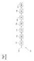
- FIG. 1shows a block diagram of an optical coherent receiver based on digital signal processing (DSP);
- DSPdigital signal processing
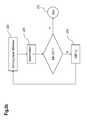
- FIG. 2 ashows a block diagram of a DSP-based coherent receiver according to the proposed solution
- FIG. 2 bshows an exemplary flow chart of the proposed solution
- FIG. 3shows a histogram of the derived phase difference of a 16 QAM modulated signal
- FIG. 4shows a histogram of the derived phase difference of the 4 th power of a 16 QAM modulated signal
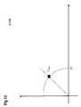
- FIG. 5shows a 16 QAM constellation diagram to the 4 th -power
- FIG. 6exemplarily shows a derived cost function CF for determining an optimized value of the nonlinear coefficient ⁇ based on a 16 QAM modulated signal over a standard single-mode fiber;
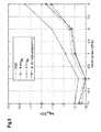
- FIG. 7shows an example of a derived cost function based on a 16 QAM modulated signal over a large-effective area pure silica core fiber
- FIGS. 8 and 9each shows an example concerning the quality performance of the proposed method
- FIG. 10 to 13each shows a further example of a signal constellation diagram applied to the 4 th power, based on a further exemplary modulation format.
- a common used DSP-based coherent receiveris exemplarily depicted according to prior art.
- a received signal 120is digitally converted by a block of four analog-to-digital converters 101 .
- bulk chromatic dispersion and nonlinear effectsare compensated by a Digital Back-Propagation (DBP) algorithm implemented by a DBP Module 102 .
- DBPDigital Back-Propagation
- a signal polarization de-multiplexingis performed by a time domain equalizer 104 , which can also be implemented in a carrier recovery module 105 .
- the succeeding stepsprocess received coherent signals via the modules carrier recovery 105 , decision making on received symbols 106 and estimation of a bit error rate 107 .
- the coherent receivercan be refined as a data-aided receiver (i.e. using training sequences (TS)). Nevertheless, the proposed method can also be realized by utilizing a receiver, which operates without training sequences (also referred to as “blind receiver”).
- TStraining sequences
- the DBP algorithm or DBP module 102requires a description of the link, which is used for back-propagation purposes. It is one of the advantages of the proposed solution that DBP can be used even by applying an arbitrary or incorrect link description. An incorrect link description can result (among others) the following, statistically independent, sources of errors:
- Homogeneous linkscomprise equal fibers for all spans (an optical fiber/cable terminated at both ends which may include devices that add, subtract, or attenuate optical signals) which is the usual scenario for point-to-point connections.
- Inhomogeneous linksare usually found in meshed optical networks, where links comprising the same type of fiber can hardly be found.
- the error on estimating the length of a single link or spandoes not really cause a problem as, after compensation of linear and nonlinear effects, this error will be averaged out—provided that the error is confined to a reasonable range. Errors of up to 20% on the length specification do not induce any significant impairment, in case DBP is used.
- the coherent receiver 200 shown in FIG. 2 ais based on the receiver according to FIG. 1 .
- a feedback connection 220is provided between the carrier recovery module 105 and the DBP module which is now an adaptive DBP (A-DBP) module 202 .
- A-DBPadaptive DBP
- an adaptive estimation module 210is part of the feedback connection 220 .
- a signal 230 which is the resulting outcome of the carrier recovery 105is passed on to the Estimation Module 210 , where the nonlinear coefficient parameter ⁇ (“Gamma”) is estimated or calculated respectively by processing the internal signal 230 forwarded from the carrier recovery module 105 as will be described further below.
- a wrong description with regard to the type of fibercan initially be provided to the adaptive DBP module 202 . Additionally, a correct description of a dispersion parameter is provided to the adaptive DBP module 202 . Apart from this, further knowledge being available concerning the link will be the number of spans and the individual length of the spans.
- the initial value of the nonlinear coefficient ⁇i.e. ⁇ (0)
- the proposed initial value for ⁇ (0)can be set (e.g., per default) at 1.3 1/(W*km), which may correspond to an average value for commercially available fibers.
- ⁇ (1)indicates the next iteration after ⁇ (0).
- the actual selected value of the nonlinear coefficient ⁇(represented by signal 231 in FIG. 2 ) is forwarded to the Adaptive DBP Module 202 .
- training sequences (TS) being part of the received signal 120are extracted and used to derive the residual nonlinear phase difference between received and (originally) transmitted symbols or sequences of symbols—see step 250 in FIG. 2 b . It is noted that this is also possible without any training sequence by deriving the residual nonlinear phase difference between received symbols and respective symbols after decision, (which is also called “blind method” or “blind receiver”).
- FIG. 3presents the respective histogram 300 of the derived phase difference ⁇ (t) of such kind of 16 QAM modulated signal, comprising 12 peaks corresponding to the 12 phases of a 16 QAM modulated signal, whereby the value of the phase difference ⁇ (t) at the very left and right side of the histogram 300 represent the same angle.
- This phase informationcan be obtained by mathematically manipulating the phase information being part of the received symbols (e.g., elimination of phase ambiguity).
- the 4 th poweris applied to the incoming signal 120 before deriving the residual nonlinear phase difference at the adaptive Estimation Module 210 .
- the respective histogram 400 of the 4 th power signalis shown in FIG. 4 where only three phases of a single quadrant can be identified accordingly.
- This information(“spreading of received symbols”), presented in FIG. 4 , is the basis for calculating the nonlinear coefficient ⁇ by deriving and evaluating a cost function as suggested—step 251 in FIG. 2 b.
- CF[ ⁇ ⁇ 1 + ⁇ ⁇ 3 ]*(1/ R 2 )+ ⁇ ⁇ 2 *(1/ R 1 +1/ R 3 )
- the cost function CFis the basis for estimating a variation ⁇ of gamma, which is now explained in more detail:
- An optimized (in the purpose of improved) value of the nonlinear coefficient ⁇can be calculated by minimizing the cost function CF mentioned above.
- the algorithm for optimizing the nonlinear coefficient value ⁇e.g., according to the “steepest descent algorithm”, which is a known optimization algorithm, “http://en.wikipedia.org/wiki/Gradient_descent”
- ⁇ ( i+ 1)⁇ ( i )+ ⁇ ( i )
- ⁇is a fiber attenuation defined in [Np/km].
- the algorithmcan also be applied by considering only the algebraic sign of the gradient.
- ⁇ (i)⁇ CF( ⁇ )/ ⁇
- ⁇ CF( ⁇ )/ ⁇is a gradient of the cost function over the nonlinear coefficient.
- the new value of the nonlinear coefficient ⁇can be determined according to:
- ⁇ ⁇ ( i + 1 )⁇ ⁇ ( i ) + ⁇ ⁇ ⁇ CF ⁇ ( ⁇ ) ⁇ ⁇
- the new value of the nonlinear coefficient ⁇ (i+1)is forwarded to the adaptive DBP module 202 , wherein the received signal 120 is processed by applying the new value ⁇ (i+1)—step 253 in FIG. 2 b.
- the gradient of the cost function CFis evaluated with respect to the previous iteration, whereas a change of the sign of the gradient indicates an end of the iteration loop, i.e. a minimum of the cost function has been reached.
- the iterative optimization algorithmcan be stopped—step 252 in FIG. 2 b.
- FIG. 6shows an example (calculated by simulated data) of the derived cost function CF as a function of the nonlinear coefficient ⁇ based on a SSMF fiber with 16-QAM.
- the algorithm for determining the optimized value of the nonlinear coefficient ⁇starts by calculating two results of the cost function CF (corresponding to two different initial values of ⁇ ).
- the convergence factor ⁇has to be optimized as well to achieve a reduction of computational time without losing quality in estimation accuracy.
- FIG. 8 and FIG. 9show examples concerning the quality performance of the proposed method based on a Log 10(BER) versus power (dBm) performance, wherein Log 10(BER) is correlated with the quality of the received signal 120 after BER calculation.
- FIG. 8is showing the Log 10(BER) versus power (dBm) performance for simulated data propagated over a 8 ⁇ 82 km LA-PSCF.
- the first curve (FDE)is showing the alignment of the signal-quality dependent from the power injected into the fiber by compensating only linear impairments using a Frequency Domain Equalizer (FDE).
- the proposed methodis working correctly, i.e. the derived optimized value of the nonlinear coefficient ⁇ after termination of the optimization algorithm according to the proposed method is exactly the same or nearly the same value like the nonlinear coefficient value ⁇ of the real fiber.
- FIG. 9is showing the Log 10(BER) versus power (dBm) performance for experimental data propagated over 8 ⁇ 82 km of SSMF.
- the first curve (FDE)is showing the alignment of the quality dependent from the power injected into the fiber by only compensating linear impairments using a Frequency Domain Equalizer (FDE).
- the aforementioned cost function CFdetermined exemplarily for processing a 16 QAM modulated signal, is one possible embodiment applying the proposed solution.
- the proposed solutioncan be applied for all kinds of modulation formats.
- CF gen⁇ k ⁇ K ⁇ [ ( ⁇ upper , k + ⁇ lower , k ) ⁇ 1 R k ] + ⁇ center ⁇ ⁇ i ⁇ I ⁇ 1 R i ⁇ with ⁇ ⁇ k ⁇ K ; i ⁇ I
- Adapting the general cost function CF gen for receiving of the 16 QAM modulated signalmay result to the following cost function CF 16 :
- CF 16⁇ k ⁇ K K max ⁇ ( ⁇ upper + ⁇ lower ) ⁇ 1 R 2 + ⁇ center ⁇ ( 1 R 1 + 1 R 3 ) with ⁇ ⁇ k ⁇ [ 2 ] ; i ⁇ [ 1 , 3 ]
- FIG. 10shows the corresponding 16 QAM constellation diagram applied to the 4 th power.
- CF 32⁇ k ⁇ K ⁇ [ ( ⁇ upper , k + ⁇ lower , k ) ⁇ 1 R k ] + ⁇ center ⁇ ⁇ i ⁇ I ⁇ 1 R i with ⁇ ⁇ k ⁇ [ 2 , 4 , 5 ] ; i ⁇ [ 1 , 3 ]
- FIG. 11shows the corresponding 32 QAM constellation diagram applied to the 4 th power.
- CF 64⁇ k ⁇ K ⁇ [ ( ⁇ upper , k + ⁇ lower , k ) ⁇ 1 R k ] + ⁇ center ⁇ ⁇ i ⁇ I ⁇ 1 R i with ⁇ ⁇ k ⁇ [ 2 , 4 , 5 , 6 , 7 , 8 ] ; i ⁇ [ 1 , 3 , 6 , 9 ]
- FIG. 12shows the corresponding 64 QAM constellation diagram to the 4 th power.
- FIG. 13shows the corresponding M-PSK constellation diagram to the 4 th power.
- the proposed solution for adaptive Digital Back Propagationis capable of a suitable set of parameters for a DBP implementation after a very short initialization cycle.
- the coding of the optimization algorithmcan be implemented in a DSP (Digital Signal Processor).
- the proposed approachcan be implemented in various optical transmission systems using coherent detection, including single carrier and multi carrier, single mode and multi mode.
Landscapes
- Physics & Mathematics (AREA)
- Nonlinear Science (AREA)
- Electromagnetism (AREA)
- Engineering & Computer Science (AREA)
- Computer Networks & Wireless Communication (AREA)
- Signal Processing (AREA)
- Optical Communication System (AREA)
Abstract
Description
- a) extracting a phase information from an optical signal received via the at least one link,
- b) determining a nonlinear coefficient, associated with the at least one link, based on the phase information,
- c) applying a control mechanism based on the nonlinear coefficient.
- the 4th power is applied to the received optical signal,
- the respective phase differences are derived from a 4th power signal,
- the cost function, based on those derived phase differences, is defined as
CF=[δθ1+δθ3]*(1/R2)+δθ2*(1/R1+1/R3)
- δθ1, δθ2, and δθ3 represent a standard deviation for each of the respective phase differences θ1 to θ3, and
- R1, R2 and R3 represent the radii of the 16 QAM constellation.
γ(i+1)=γ(i)+μΔγ(i)
- i is an index of a discrete time;
- γ(i+1) represents the value of the nonlinear coefficient at an iteration (i+1);
- γ(i) represents the value of the nonlinear coefficient at a preceding iteration step (i);
- μ represents the convergence factor, comprising an effective fiber length Leffand a channel power P;
- Δγ(i)=∂CF(γ)/∂γ is a gradient of the cost function over a nonlinear coefficient.
- a) extracting a phase information from an optical signal received via that at least one link,
- b) determining a nonlinear coefficient, associated with the at least one link, based on the phase information,
- c) applying the control mechanism using the nonlinear coefficient.
- the fiber length (which is possibly incorrect),
- the fiber type (which is possibly wrong) or
- the power levels (which can not be measured accurately)
- Large-Effective Area Pure Silica Core Fiber (LA-PSCF)
- Standard Single-Mode optical Fiber (SSMF)
Δθ(t)=θ(t)−θRX(t)
- θ(t) either represents a sequence of training symbols, (θ(t)=θTS(t)) or a sequence of already decided symbols (θ(t)=θDEC(t)) and
- θRX(t) represents the received symbols.
Δθ(t)=|θ(t)−θRX(t)|
CF=[δθ1+δθ3]*(1/R2)+δθ2*(1/R1+1/R3)
- δθ1, δθ2, and δθ3are representing the standard deviation for each of the respective phase differences as shown in
FIG. 4 , and - R1, R2 and R3 are representing the radii of the 16 QAM constellation as shown in
FIG. 5 .
- δθ1, δθ2, and δθ3are representing the standard deviation for each of the respective phase differences as shown in
γ(i+1)=γ(i)+μΔγ(i)
- i is the index of the discrete time;
- γ(i+1) represents the value of the nonlinear coefficient at the iteration (i+1);
- γ(i) represents the value of the nonlinear coefficient at the preceding iteration (i);
- μ represents a convergence factor, comprising an effective fiber length Leffand a channel power P.
Δγ(i)=∂CF(γ)/∂γ
- The information being available after carrier recovery of the received signal is sufficient for determination of the optimized value of the nonlinear coefficient γ, i.e. FEC (forward error correction) based on a BER calculation can be avoided. Advantageously, the convergence factor for estimating the optimum value of the nonlinear coefficient γ can be significantly accelerated.
- The cost function CF can be derived analytically wherein verification of the results can be achieved by post-processing simulated and experimental data.
- The robustness of the proposed approach has been verified under extreme conditions, showing that an appropriate determination of the nonlinear coefficient γ is always successful.
- CFgenis a general cost function
- δupper,krepresents a standard deviation for each of the phase differences θupperhigher than a central phase θcenterper radius Rk
- δlower,krepresents a standard deviation for each of the phase differences θlowerlower than the central phase Θcentralcentral per radius Rk
- Θδcenterrepresents a central phase.
- I represents a set of distinct radii of the signal constellation
- K represents a set of distinct phase angles of the histogram of the signal constellation after a M-th power operation
- DBP Digital Back-Propagation
- DEC Decision
- DSP Digital Signal Processor
- DWDM Dense Wavelength Division Multiplex
- BER Bit Error Rate
- CD Chromatic Dispersion
- CF Cost Function
- CPR Carrier Phase Recovery
- CR Clock Recovery
- DSP Digital Signal Processing
- DM Dispersion Managed
- FDE Frequency-Domain Equalizer
- NDM Non-Dispersion Managed
- NLPN Nonlinear Phase Noise
- PMD Polarization Mode Dispersion
- RX Receive
- SPM Self Phase Modulation
- TDE Time-Domain Equalizer
- TS Training Sequence
- XPM Cross Phase Modulation
Claims (11)
γ(i+1)=γ(i)+μΔγ(i), wherein
CF=[δθ1+δθ3]*(1/R2)+δθ2*(1/R1+1/R3)
γ(i+1)=γ(i)+μΔγ(i), wherein
Applications Claiming Priority (4)
| Application Number | Priority Date | Filing Date | Title |
|---|---|---|---|
| EP13167440.0AEP2804334A1 (en) | 2013-05-13 | 2013-05-13 | Method, device and communication system for reducing optical transmission impairments |
| EP13167440.0 | 2013-05-13 | ||
| EP13167440 | 2013-05-13 | ||
| PCT/EP2014/059654WO2014184139A1 (en) | 2013-05-13 | 2014-05-12 | Method, device and communication system for reducing optical transmission impairments |
Publications (2)
| Publication Number | Publication Date |
|---|---|
| US20160127047A1 US20160127047A1 (en) | 2016-05-05 |
| US10439730B2true US10439730B2 (en) | 2019-10-08 |
Family
ID=48326190
Family Applications (1)
| Application Number | Title | Priority Date | Filing Date |
|---|---|---|---|
| US14/890,373ActiveUS10439730B2 (en) | 2013-05-13 | 2014-05-12 | Method, device and communication system for reducing optical transmission impairments |
Country Status (4)
| Country | Link |
|---|---|
| US (1) | US10439730B2 (en) |
| EP (2) | EP2804334A1 (en) |
| CN (1) | CN105432029B (en) |
| WO (1) | WO2014184139A1 (en) |
Families Citing this family (15)
| Publication number | Priority date | Publication date | Assignee | Title |
|---|---|---|---|---|
| EP2804334A1 (en) | 2013-05-13 | 2014-11-19 | Xieon Networks S.à.r.l. | Method, device and communication system for reducing optical transmission impairments |
| GB201605120D0 (en)* | 2016-03-24 | 2016-05-11 | Univ Aston | System and method for the transmission of optic signals |
| JP6759742B2 (en)* | 2016-06-16 | 2020-09-23 | 富士通株式会社 | Receiver and setting method |
| EP3324169A1 (en)* | 2016-11-22 | 2018-05-23 | Xieon Networks S.à r.l. | Detection of gainers and exaggerated losses in unidirectional otdr traces |
| US10887022B2 (en)* | 2017-06-15 | 2021-01-05 | Nokia Of America Corporation | Backward propagation with compensation of some nonlinear effects of polarization mode dispersion |
| US10833770B2 (en)* | 2018-06-22 | 2020-11-10 | Nec Corporation | Optical fiber nonlinearity compensation using neural networks |
| CN110336609B (en)* | 2019-05-31 | 2021-03-30 | 中山大学 | A method for optimizing multi-span optical fiber transmission system |
| CN111457927B (en)* | 2020-04-26 | 2021-03-05 | 北京工商大学 | Multi-objective path planning method for unmanned cruise ship under dynamic obstacles |
| CN111917474B (en)* | 2020-07-22 | 2022-07-29 | 北京理工大学 | An Implicit Triad Neural Network and Optical Fiber Nonlinear Damage Equalization Method |
| CN114553314B (en)* | 2020-11-27 | 2023-08-22 | 华为技术有限公司 | Nonlinear damage compensation method, device, transmission equipment and storage medium |
| CN113595641B (en)* | 2021-07-23 | 2022-05-17 | 成都信息工程大学 | An Optical Fiber Nonlinear Equalization Method Based on MA-DBP Algorithm |
| CN113703199B (en)* | 2021-07-30 | 2024-02-20 | 山东师范大学 | Method and device for improving light field coherence self-repairing capability |
| CN114629766B (en)* | 2022-01-30 | 2023-09-05 | 北京邮电大学 | Symbol judgment method, device, electronic equipment and storage medium in optical fiber communication |
| CN115173940B (en)* | 2022-06-27 | 2024-04-23 | 华中科技大学 | Method and system for monitoring link joint damage of multi-channel optical transmission system |
| CN117081677B (en)* | 2023-10-13 | 2023-12-15 | 湖北大学 | A method and equipment for processing inter-carrier damage in SEFDM system |
Citations (47)
| Publication number | Priority date | Publication date | Assignee | Title |
|---|---|---|---|---|
| US20050019042A1 (en)* | 2003-07-25 | 2005-01-27 | Noriaki Kaneda | Method and apparatus for electronic equalization in optical communication systems |
| US20090190926A1 (en)* | 2008-01-29 | 2009-07-30 | Gabriel Charlet | Combined phase and polarization modulation for optical communication |
| US20090245809A1 (en)* | 2008-03-27 | 2009-10-01 | Fujitsu Limited | Optical transmission system |
| US20100014873A1 (en)* | 2008-07-16 | 2010-01-21 | Henning Bulow | Adaptive non-linearity compensation in coherent receiver |
| US20100232796A1 (en)* | 2009-03-10 | 2010-09-16 | Tyco Electronics Subsea Communications, Llc | Data Pattern Dependent Distortion Compensation in a Coherent Optical Signal Receiver |
| US20110255879A1 (en)* | 2010-04-16 | 2011-10-20 | Chongjin Xie | Electronic Nonlinearity Compensation For Optical Transmission Systems |
| US20110318014A1 (en)* | 2009-03-19 | 2011-12-29 | Luxdyne Oy | Noise suppression in an optical apparatus |
| US8095019B2 (en)* | 2008-07-30 | 2012-01-10 | Alcatel Lucent | Digital clock and data recovery scheme |
| US20120027418A1 (en)* | 2009-02-20 | 2012-02-02 | Telefonaktiebolaget Lm Ericsson (Publ) | Equalizer for an Optical Transmission System |
| US20120051742A1 (en)* | 2010-08-31 | 2012-03-01 | Fujitsu Limited | Apparatus for self-phase modulation noise calculation, apparatus for self-phase modulation noise elimination and optical coherent receiver |
| US20120076235A1 (en)* | 2010-09-28 | 2012-03-29 | Fujitsu Limited | Nonlinear compensating apparatus and transmitter |
| US20120082468A1 (en)* | 2010-08-20 | 2012-04-05 | Nec Laboratories America, Inc. | Look-up table and digital transmitter based architecture for fiber nonlinearity compensation |
| US20120290244A1 (en)* | 2011-03-04 | 2012-11-15 | Fujitsu Limited | Method and apparatus for compensating nonlinear damage |
| US20130084080A1 (en)* | 2011-10-04 | 2013-04-04 | Nec Corporation | Coherent optical receiver and coherent optical receiving method |
| US20130108260A1 (en)* | 2011-10-28 | 2013-05-02 | Fujitsu Limited | Method and apparatus for adaptive nonlinear equalization in a polarization multiplexing optical communication system |
| US8447190B2 (en)* | 2009-01-30 | 2013-05-21 | Fujitsu Limited | Distortion compensating apparatus, optical receiving apparatus, and optical transmitting and receiving system |
| US8478137B2 (en)* | 2010-02-12 | 2013-07-02 | Fujitsu Limited | Optical receiver |
| US20130195459A1 (en)* | 2010-03-19 | 2013-08-01 | Ofidium Pty Ltd. | Method and apparatus for fiber non-linearity mitigation |
| US20130209089A1 (en)* | 2012-02-13 | 2013-08-15 | Ciena Corporation | Constrained continuous phase modulation and demodulation in an optical communications system |
| US20130230313A1 (en)* | 2011-03-04 | 2013-09-05 | Fujitsu Limited | Method and apparatus for compensating nonlinear damage |
| US20130243433A1 (en)* | 2012-03-16 | 2013-09-19 | Fujitsu Limited | Inverse channel apparatus and transmitter, receiver and system containing the apparatus |
| US20130251370A1 (en)* | 2011-02-01 | 2013-09-26 | Nec Corporation | Optical receiver, polarization separation device and polarization separating method |
| US8553821B1 (en)* | 2012-06-20 | 2013-10-08 | MagnaCom Ltd. | Adaptive non-linear model for highly-spectrally-efficient communications |
| US20130302041A1 (en)* | 2011-02-02 | 2013-11-14 | Nec Corporation | Optical receiver and method for optical reception |
| US20130308960A1 (en)* | 2011-02-07 | 2013-11-21 | Nippon Telegraph And Telephone Corporation | Digital signal processing apparatus |
| US20140093255A1 (en)* | 2011-12-01 | 2014-04-03 | Huawei Technologies Co., Ltd. | Optical signal compensation device |
| US20140099128A1 (en)* | 2012-10-09 | 2014-04-10 | Nec Laboratories America, Inc. | Inter-band cross-phase modulation compensation for the mitigation of intra-channel nonlinear impairments in optical fiber transmission |
| US20140247906A1 (en)* | 2011-11-16 | 2014-09-04 | Huawei Technologies Co., Ltd. | Microwave Predistorted Signal Generating Method and Apparatus |
| US20140286642A1 (en)* | 2010-12-22 | 2014-09-25 | Ofidium Pty Ltd | Electronic compensation of cross-phase modulation |
| WO2014184139A1 (en) | 2013-05-13 | 2014-11-20 | Xieon Networks S.A.R.L. | Method, device and communication system for reducing optical transmission impairments |
| US20150071630A1 (en)* | 2013-09-11 | 2015-03-12 | Fujitsu Limited | Non-linear distortion compensator, method of compensating non-linear distortion, and optical receiver |
| US20150104189A1 (en)* | 2013-10-15 | 2015-04-16 | Fujitsu Limited | Compensation apparatus and method for inter-channel nonlinear damage |
| US20150236795A1 (en)* | 2012-03-29 | 2015-08-20 | Juniper Networks, Inc. | Processing data in a coherent optical communication system |
| US20150288458A1 (en)* | 2014-04-07 | 2015-10-08 | Fujitsu Limited | Digital coherent receiver and receiving method of optical signal |
| US20150295649A1 (en)* | 2014-04-11 | 2015-10-15 | Futurewei Technologies, Inc. | Method and system for performing fiber nonlinearity compensation for optical 16qam |
| US20150372765A1 (en)* | 2013-02-07 | 2015-12-24 | Nec Corporation | Signal processing device and signal processing method |
| US9225429B2 (en)* | 2012-12-21 | 2015-12-29 | Zte Corporation | Recovering data from quadrature phase shift keying modulated optical signals |
| US20160036528A1 (en)* | 2013-04-10 | 2016-02-04 | Fujitsu Limited | Calculating apparatus and method for nonlinear weighting coefficient |
| US20160036554A1 (en)* | 2013-04-09 | 2016-02-04 | Nec Corporation | Signal processing device and signal processing method |
| US9258060B2 (en)* | 2012-04-11 | 2016-02-09 | Fujitsu Limited | Method and apparatus for compensating nonlinear distortions in intensity modulation-direct detection system |
| US20160065312A1 (en)* | 2014-09-03 | 2016-03-03 | Fujitsu Limited | Optical transmission device, nonlinear distortion compensation method, and nonlinear distortion pre-equalization method |
| US20160094292A1 (en)* | 2014-09-25 | 2016-03-31 | Fujitsu Limited | Signal processing device and signal processing method |
| US20160226582A1 (en)* | 2015-01-30 | 2016-08-04 | Fujitsu Limited | Estimating device and method for estimating |
| US20160294480A1 (en)* | 2015-03-31 | 2016-10-06 | Infinera Corp. | System and method for determining nonlinear mitigation perturbative distortion coefficients using a received optical signal |
| US20170264468A1 (en)* | 2016-03-14 | 2017-09-14 | Mitsubishi Electric Research Laboratories, Inc. | Frequency Domain Equalizer for Optical Communications |
| US20180034552A1 (en)* | 2016-07-27 | 2018-02-01 | Fujitsu Limited | Signal processing device used in optical receiver and signal processing method |
| US20180234184A1 (en)* | 2017-02-16 | 2018-08-16 | Fujitsu Limited | Monitor device and monitor method for monitoring transmission line |
Family Cites Families (2)
| Publication number | Priority date | Publication date | Assignee | Title |
|---|---|---|---|---|
| CN102136866B (en)* | 2010-12-09 | 2014-07-30 | 华为技术有限公司 | Optical transmission equipment, optical transmission system and optical transmission parameter configuration method |
| CN103023570B (en)* | 2011-09-26 | 2016-03-30 | 富士通株式会社 | Nonlinear compensating device, method and transmitter |
- 2013
- 2013-05-13EPEP13167440.0Apatent/EP2804334A1/ennot_activeWithdrawn
- 2014
- 2014-05-12EPEP14729222.1Apatent/EP2997676B1/enactiveActive
- 2014-05-12WOPCT/EP2014/059654patent/WO2014184139A1/enactiveApplication Filing
- 2014-05-12USUS14/890,373patent/US10439730B2/enactiveActive
- 2014-05-12CNCN201480027244.7Apatent/CN105432029B/enactiveActive
Patent Citations (47)
| Publication number | Priority date | Publication date | Assignee | Title |
|---|---|---|---|---|
| US20050019042A1 (en)* | 2003-07-25 | 2005-01-27 | Noriaki Kaneda | Method and apparatus for electronic equalization in optical communication systems |
| US20090190926A1 (en)* | 2008-01-29 | 2009-07-30 | Gabriel Charlet | Combined phase and polarization modulation for optical communication |
| US20090245809A1 (en)* | 2008-03-27 | 2009-10-01 | Fujitsu Limited | Optical transmission system |
| US20100014873A1 (en)* | 2008-07-16 | 2010-01-21 | Henning Bulow | Adaptive non-linearity compensation in coherent receiver |
| US8095019B2 (en)* | 2008-07-30 | 2012-01-10 | Alcatel Lucent | Digital clock and data recovery scheme |
| US8447190B2 (en)* | 2009-01-30 | 2013-05-21 | Fujitsu Limited | Distortion compensating apparatus, optical receiving apparatus, and optical transmitting and receiving system |
| US20120027418A1 (en)* | 2009-02-20 | 2012-02-02 | Telefonaktiebolaget Lm Ericsson (Publ) | Equalizer for an Optical Transmission System |
| US20100232796A1 (en)* | 2009-03-10 | 2010-09-16 | Tyco Electronics Subsea Communications, Llc | Data Pattern Dependent Distortion Compensation in a Coherent Optical Signal Receiver |
| US20110318014A1 (en)* | 2009-03-19 | 2011-12-29 | Luxdyne Oy | Noise suppression in an optical apparatus |
| US8478137B2 (en)* | 2010-02-12 | 2013-07-02 | Fujitsu Limited | Optical receiver |
| US20130195459A1 (en)* | 2010-03-19 | 2013-08-01 | Ofidium Pty Ltd. | Method and apparatus for fiber non-linearity mitigation |
| US20110255879A1 (en)* | 2010-04-16 | 2011-10-20 | Chongjin Xie | Electronic Nonlinearity Compensation For Optical Transmission Systems |
| US20120082468A1 (en)* | 2010-08-20 | 2012-04-05 | Nec Laboratories America, Inc. | Look-up table and digital transmitter based architecture for fiber nonlinearity compensation |
| US20120051742A1 (en)* | 2010-08-31 | 2012-03-01 | Fujitsu Limited | Apparatus for self-phase modulation noise calculation, apparatus for self-phase modulation noise elimination and optical coherent receiver |
| US20120076235A1 (en)* | 2010-09-28 | 2012-03-29 | Fujitsu Limited | Nonlinear compensating apparatus and transmitter |
| US20140286642A1 (en)* | 2010-12-22 | 2014-09-25 | Ofidium Pty Ltd | Electronic compensation of cross-phase modulation |
| US20130251370A1 (en)* | 2011-02-01 | 2013-09-26 | Nec Corporation | Optical receiver, polarization separation device and polarization separating method |
| US20130302041A1 (en)* | 2011-02-02 | 2013-11-14 | Nec Corporation | Optical receiver and method for optical reception |
| US20130308960A1 (en)* | 2011-02-07 | 2013-11-21 | Nippon Telegraph And Telephone Corporation | Digital signal processing apparatus |
| US20130230313A1 (en)* | 2011-03-04 | 2013-09-05 | Fujitsu Limited | Method and apparatus for compensating nonlinear damage |
| US20120290244A1 (en)* | 2011-03-04 | 2012-11-15 | Fujitsu Limited | Method and apparatus for compensating nonlinear damage |
| US20130084080A1 (en)* | 2011-10-04 | 2013-04-04 | Nec Corporation | Coherent optical receiver and coherent optical receiving method |
| US20130108260A1 (en)* | 2011-10-28 | 2013-05-02 | Fujitsu Limited | Method and apparatus for adaptive nonlinear equalization in a polarization multiplexing optical communication system |
| US20140247906A1 (en)* | 2011-11-16 | 2014-09-04 | Huawei Technologies Co., Ltd. | Microwave Predistorted Signal Generating Method and Apparatus |
| US20140093255A1 (en)* | 2011-12-01 | 2014-04-03 | Huawei Technologies Co., Ltd. | Optical signal compensation device |
| US20130209089A1 (en)* | 2012-02-13 | 2013-08-15 | Ciena Corporation | Constrained continuous phase modulation and demodulation in an optical communications system |
| US20130243433A1 (en)* | 2012-03-16 | 2013-09-19 | Fujitsu Limited | Inverse channel apparatus and transmitter, receiver and system containing the apparatus |
| US20150236795A1 (en)* | 2012-03-29 | 2015-08-20 | Juniper Networks, Inc. | Processing data in a coherent optical communication system |
| US9258060B2 (en)* | 2012-04-11 | 2016-02-09 | Fujitsu Limited | Method and apparatus for compensating nonlinear distortions in intensity modulation-direct detection system |
| US8553821B1 (en)* | 2012-06-20 | 2013-10-08 | MagnaCom Ltd. | Adaptive non-linear model for highly-spectrally-efficient communications |
| US20140099128A1 (en)* | 2012-10-09 | 2014-04-10 | Nec Laboratories America, Inc. | Inter-band cross-phase modulation compensation for the mitigation of intra-channel nonlinear impairments in optical fiber transmission |
| US9225429B2 (en)* | 2012-12-21 | 2015-12-29 | Zte Corporation | Recovering data from quadrature phase shift keying modulated optical signals |
| US20150372765A1 (en)* | 2013-02-07 | 2015-12-24 | Nec Corporation | Signal processing device and signal processing method |
| US20160036554A1 (en)* | 2013-04-09 | 2016-02-04 | Nec Corporation | Signal processing device and signal processing method |
| US20160036528A1 (en)* | 2013-04-10 | 2016-02-04 | Fujitsu Limited | Calculating apparatus and method for nonlinear weighting coefficient |
| WO2014184139A1 (en) | 2013-05-13 | 2014-11-20 | Xieon Networks S.A.R.L. | Method, device and communication system for reducing optical transmission impairments |
| US20150071630A1 (en)* | 2013-09-11 | 2015-03-12 | Fujitsu Limited | Non-linear distortion compensator, method of compensating non-linear distortion, and optical receiver |
| US20150104189A1 (en)* | 2013-10-15 | 2015-04-16 | Fujitsu Limited | Compensation apparatus and method for inter-channel nonlinear damage |
| US20150288458A1 (en)* | 2014-04-07 | 2015-10-08 | Fujitsu Limited | Digital coherent receiver and receiving method of optical signal |
| US20150295649A1 (en)* | 2014-04-11 | 2015-10-15 | Futurewei Technologies, Inc. | Method and system for performing fiber nonlinearity compensation for optical 16qam |
| US20160065312A1 (en)* | 2014-09-03 | 2016-03-03 | Fujitsu Limited | Optical transmission device, nonlinear distortion compensation method, and nonlinear distortion pre-equalization method |
| US20160094292A1 (en)* | 2014-09-25 | 2016-03-31 | Fujitsu Limited | Signal processing device and signal processing method |
| US20160226582A1 (en)* | 2015-01-30 | 2016-08-04 | Fujitsu Limited | Estimating device and method for estimating |
| US20160294480A1 (en)* | 2015-03-31 | 2016-10-06 | Infinera Corp. | System and method for determining nonlinear mitigation perturbative distortion coefficients using a received optical signal |
| US20170264468A1 (en)* | 2016-03-14 | 2017-09-14 | Mitsubishi Electric Research Laboratories, Inc. | Frequency Domain Equalizer for Optical Communications |
| US20180034552A1 (en)* | 2016-07-27 | 2018-02-01 | Fujitsu Limited | Signal processing device used in optical receiver and signal processing method |
| US20180234184A1 (en)* | 2017-02-16 | 2018-08-16 | Fujitsu Limited | Monitor device and monitor method for monitoring transmission line |
Non-Patent Citations (11)
| Title |
|---|
| ASIF RAMEEZ, ET AL.: "Optimized digital backward propagation for phase modulated signals in mixed-optical fiber transmission links", OPTICS EXPRESS, OSA PUBLISHING, US, vol. 18, no. 22, 25 October 2010 (2010-10-25), US, pages 22796, XP002715061, ISSN: 1094-4087, DOI: 10.1364/OE.18.022796 |
| Asif, R. et al., "Optimized Digital Backward Propagation for Phase Modulated Signals in Mixed-Optical Fiber Transmission Links," Optics Express, vol. 18(22) pp. 22796-22807, Oct. 25, 2010, XP002715061. |
| Bermudez, Adaptive Filtering Theory and Applications, May 2011, IRIT, All Document.* |
| F. P. GUIOMAR ; A. N. PINTO: "Optimizing the nonlinear operator in backward propagation", EUROCON - INTERNATIONAL CONFERENCE ON COMPUTER AS A TOOL (EUROCON), 2011 IEEE, 27-29 APRIL 2011, LISBON PORTUGAL, IEEE, PISCATAWAY, NJ, 27 April 2011 (2011-04-27), Piscataway, NJ, pages 1 - 4, XP031949634, ISBN: 978-1-4244-7486-8, DOI: 10.1109/EUROCON.2011.5929356 |
| Guiomar, F. P. et al., "Optimizing the Nonlinear Operator in Backward Propagation," Eurocon International Conference on Computer as a Tool (EUROCON), 2011 IEEE, Apr. 27-29, 2011, Lisbon Portugal, IEEE, Piscataway, NJ, Apr. 27, 2011, pp. 1-4, XP031949634,DOI: 10.1109/EUROCON.2011.5929356 ISBN: 978-1-4244-7486-8. |
| International Search Report and Written Opinion, PCT/EP2014/059654, dated Aug. 18, 2014, 10 pages. |
| Pan et al, Volterra Filtering for Nonlinearity Impairment Mitigation in DP 16QAM and DP QPSK Fiber Optic Communication Systems, Jun. 2011, IEEE, OSA, All Document.* |
| Peng et al, Per symbol based digital back propagation approach for PDM CO OFDM transmission systems, Jan. 2013, Optics Express vol. 21, No. 2, Pages All Document. (Year: 2013).* |
| Regev, EVM Test Impairements, May 2012, Presto Engineering, Pages All Document. https://www.slideshare.net/chiportal/evm-test-impairements.* |
| TAKAHITO TANIMURA ; TAKESHI HOSHIDA ; TOSHIKI TANAKA ; LEI LI ; SHOICHIRO ODA ; HISAO NAKASHIMA ; ZHENNING TAO ; JENS C RASMUSSEN: "Semi-blind nonlinear equalization in coherent multi-span transmission system with inhomogeneous span parameters", OPTICAL FIBER COMMUNICATION (OFC), COLLOCATED NATIONAL FIBER OPTIC ENGINEERS CONFERENCE, 2010 CONFERENCE ON (OFC/NFOEC), IEEE, PISCATAWAY, NJ, USA, 21 March 2010 (2010-03-21), Piscataway, NJ, USA, pages 1 - 3, XP031676785 |
| Tanimura, T. et al., "Semi-blind Nonlinear Equalization in Coherent Multi-Span Transmission System with Inhomogeneous Span Parameters," Optical Fiber Communication (OFC), Collocated National Fiber Optic Engineers Conference, 2010 Conference on (OFC/NFOEC), IEEE, Piscataway, NJ, USA, Mar. 21, 2010, pp. 1-3, XP031676785. |
Also Published As
| Publication number | Publication date |
|---|---|
| WO2014184139A1 (en) | 2014-11-20 |
| CN105432029A (en) | 2016-03-23 |
| EP2997676B1 (en) | 2020-05-06 |
| CN105432029B (en) | 2018-11-09 |
| EP2804334A1 (en) | 2014-11-19 |
| US20160127047A1 (en) | 2016-05-05 |
| EP2997676A1 (en) | 2016-03-23 |
Similar Documents
| Publication | Publication Date | Title |
|---|---|---|
| US10439730B2 (en) | Method, device and communication system for reducing optical transmission impairments | |
| Sasai et al. | Digital longitudinal monitoring of optical fiber communication link | |
| Frey et al. | Single-step perturbation-based nonlinearity compensation of intra-and inter-subcarrier nonlinear interference | |
| EP2922221B1 (en) | Techniques for blind equalization of high-order quadrature amplitude modulation signals | |
| US11777612B2 (en) | Method for nonlinear compensation of coherent high-capacity high-order qam system | |
| US20100014873A1 (en) | Adaptive non-linearity compensation in coherent receiver | |
| EP3096470B1 (en) | Method and system for nonlinear interference mitigation | |
| US11270200B2 (en) | Single-step nonlinearity compensation using artificial intelligence for digital coherent transmission systems | |
| Lin et al. | Adaptive digital back-propagation for optical communication systems | |
| EP2858272B1 (en) | Non-linear distortion compensator, method of compensating non-linear distortion, and optical receiver | |
| Pan et al. | Chromatic dispersion monitoring and automated compensation for NRZ and RZ data using clock regeneration and fading without adding signaling | |
| US10148465B2 (en) | Training assisted joint equalization | |
| US9628189B2 (en) | System optimization of pulse shaping filters in fiber optic networks | |
| Do et al. | Data-aided OSNR estimation for QPSK and 16-QAM coherent optical system | |
| Chen et al. | Full-field, carrier-less, polarization-diversity, direct detection receiver based on phase retrieval | |
| Jiang et al. | Chromatic dispersion, nonlinear parameter, and modulation Format monitoring based on Godard's error for coherent optical transmission systems | |
| CN118282510A (en) | Multi-eigenvalue optical communication system based on neural network compensator | |
| Frey et al. | Improved perturbation-based fiber nonlinearity compensation | |
| Liang et al. | Perturbation-assisted DBP for nonlinear compensation in polarization multiplexed systems | |
| Ip et al. | Nonlinear impairment compensation using backpropagation | |
| EP3133751A1 (en) | Method for nonlinearity compensation in optical transmission systems | |
| Martelli et al. | Crosstalk-induced penalty in coherent space-division multiplexing transmission | |
| Abdullah et al. | DSP techniques for reducing chromatic dispersion in optical communication systems | |
| Hoshida et al. | Network innovations brought by digital coherent receivers | |
| Chin et al. | Volterra based nonlinear compensation on 224 Gb/s PolMux-16QAM optical fibre link |
Legal Events
| Date | Code | Title | Description |
|---|---|---|---|
| AS | Assignment | Owner name:XIEON NETWORKS S.A.R.L., LUXEMBOURG Free format text:ASSIGNMENT OF ASSIGNORS INTEREST;ASSIGNORS:NAPOLI, ANTONIO;LIN, CHIEN-YU;SPINNLER, BERNHARD;AND OTHERS;SIGNING DATES FROM 20160127 TO 20160204;REEL/FRAME:037897/0033 | |
| AS | Assignment | Owner name:CERBERUS BUSINESS FINANCE, LLC, AS COLLATERAL AGEN Free format text:SECURITY INTEREST;ASSIGNOR:XIEON NETWORKS S.A R.L.;REEL/FRAME:040776/0088 Effective date:20161227 | |
| AS | Assignment | Owner name:XIEON NETWORKS S.A.R.L., ILLINOIS Free format text:RELEASE BY SECURED PARTY;ASSIGNOR:CERBERUS BUSINESS FINANCE, LLC;REEL/FRAME:047335/0952 Effective date:20181001 | |
| STPP | Information on status: patent application and granting procedure in general | Free format text:NON FINAL ACTION MAILED | |
| STPP | Information on status: patent application and granting procedure in general | Free format text:NOTICE OF ALLOWANCE MAILED -- APPLICATION RECEIVED IN OFFICE OF PUBLICATIONS | |
| STPP | Information on status: patent application and granting procedure in general | Free format text:PUBLICATIONS -- ISSUE FEE PAYMENT RECEIVED | |
| STPP | Information on status: patent application and granting procedure in general | Free format text:PUBLICATIONS -- ISSUE FEE PAYMENT VERIFIED | |
| STCF | Information on status: patent grant | Free format text:PATENTED CASE | |
| MAFP | Maintenance fee payment | Free format text:PAYMENT OF MAINTENANCE FEE, 4TH YEAR, LARGE ENTITY (ORIGINAL EVENT CODE: M1551); ENTITY STATUS OF PATENT OWNER: LARGE ENTITY Year of fee payment:4 |