US10437463B2 - Motion-based graphical input system - Google Patents
Motion-based graphical input systemDownload PDFInfo
- Publication number
- US10437463B2 US10437463B2US15/295,907US201615295907AUS10437463B2US 10437463 B2US10437463 B2US 10437463B2US 201615295907 AUS201615295907 AUS 201615295907AUS 10437463 B2US10437463 B2US 10437463B2
- Authority
- US
- United States
- Prior art keywords
- data
- input
- virtual
- motion
- dimensional space
- Prior art date
- Legal status (The legal status is an assumption and is not a legal conclusion. Google has not performed a legal analysis and makes no representation as to the accuracy of the status listed.)
- Expired - Fee Related
Links
Images


Classifications
- G—PHYSICS
- G06—COMPUTING OR CALCULATING; COUNTING
- G06F—ELECTRIC DIGITAL DATA PROCESSING
- G06F3/00—Input arrangements for transferring data to be processed into a form capable of being handled by the computer; Output arrangements for transferring data from processing unit to output unit, e.g. interface arrangements
- G06F3/01—Input arrangements or combined input and output arrangements for interaction between user and computer
- G06F3/048—Interaction techniques based on graphical user interfaces [GUI]
- G06F3/0487—Interaction techniques based on graphical user interfaces [GUI] using specific features provided by the input device, e.g. functions controlled by the rotation of a mouse with dual sensing arrangements, or of the nature of the input device, e.g. tap gestures based on pressure sensed by a digitiser
- G06F3/0488—Interaction techniques based on graphical user interfaces [GUI] using specific features provided by the input device, e.g. functions controlled by the rotation of a mouse with dual sensing arrangements, or of the nature of the input device, e.g. tap gestures based on pressure sensed by a digitiser using a touch-screen or digitiser, e.g. input of commands through traced gestures
- G06F3/04883—Interaction techniques based on graphical user interfaces [GUI] using specific features provided by the input device, e.g. functions controlled by the rotation of a mouse with dual sensing arrangements, or of the nature of the input device, e.g. tap gestures based on pressure sensed by a digitiser using a touch-screen or digitiser, e.g. input of commands through traced gestures for inputting data by handwriting, e.g. gesture or text
- G—PHYSICS
- G06—COMPUTING OR CALCULATING; COUNTING
- G06F—ELECTRIC DIGITAL DATA PROCESSING
- G06F3/00—Input arrangements for transferring data to be processed into a form capable of being handled by the computer; Output arrangements for transferring data from processing unit to output unit, e.g. interface arrangements
- G06F3/01—Input arrangements or combined input and output arrangements for interaction between user and computer
- G06F3/017—Gesture based interaction, e.g. based on a set of recognized hand gestures
- G—PHYSICS
- G06—COMPUTING OR CALCULATING; COUNTING
- G06F—ELECTRIC DIGITAL DATA PROCESSING
- G06F3/00—Input arrangements for transferring data to be processed into a form capable of being handled by the computer; Output arrangements for transferring data from processing unit to output unit, e.g. interface arrangements
- G06F3/01—Input arrangements or combined input and output arrangements for interaction between user and computer
- G06F3/03—Arrangements for converting the position or the displacement of a member into a coded form
- G06F3/033—Pointing devices displaced or positioned by the user, e.g. mice, trackballs, pens or joysticks; Accessories therefor
- G06F3/0346—Pointing devices displaced or positioned by the user, e.g. mice, trackballs, pens or joysticks; Accessories therefor with detection of the device orientation or free movement in a 3D space, e.g. 3D mice, 6-DOF [six degrees of freedom] pointers using gyroscopes, accelerometers or tilt-sensors
- G—PHYSICS
- G06—COMPUTING OR CALCULATING; COUNTING
- G06F—ELECTRIC DIGITAL DATA PROCESSING
- G06F3/00—Input arrangements for transferring data to be processed into a form capable of being handled by the computer; Output arrangements for transferring data from processing unit to output unit, e.g. interface arrangements
- G06F3/01—Input arrangements or combined input and output arrangements for interaction between user and computer
- G06F3/048—Interaction techniques based on graphical user interfaces [GUI]
- G06F3/0481—Interaction techniques based on graphical user interfaces [GUI] based on specific properties of the displayed interaction object or a metaphor-based environment, e.g. interaction with desktop elements like windows or icons, or assisted by a cursor's changing behaviour or appearance
- G06F3/04815—Interaction with a metaphor-based environment or interaction object displayed as three-dimensional, e.g. changing the user viewpoint with respect to the environment or object
- G—PHYSICS
- G06—COMPUTING OR CALCULATING; COUNTING
- G06F—ELECTRIC DIGITAL DATA PROCESSING
- G06F3/00—Input arrangements for transferring data to be processed into a form capable of being handled by the computer; Output arrangements for transferring data from processing unit to output unit, e.g. interface arrangements
- G06F3/01—Input arrangements or combined input and output arrangements for interaction between user and computer
- G06F3/048—Interaction techniques based on graphical user interfaces [GUI]
- G06F3/0487—Interaction techniques based on graphical user interfaces [GUI] using specific features provided by the input device, e.g. functions controlled by the rotation of a mouse with dual sensing arrangements, or of the nature of the input device, e.g. tap gestures based on pressure sensed by a digitiser
- G—PHYSICS
- G06—COMPUTING OR CALCULATING; COUNTING
- G06F—ELECTRIC DIGITAL DATA PROCESSING
- G06F9/00—Arrangements for program control, e.g. control units
- G06F9/06—Arrangements for program control, e.g. control units using stored programs, i.e. using an internal store of processing equipment to receive or retain programs
- G06F9/44—Arrangements for executing specific programs
- G06F9/451—Execution arrangements for user interfaces
- G06F9/453—Help systems
- G—PHYSICS
- G06—COMPUTING OR CALCULATING; COUNTING
- G06F—ELECTRIC DIGITAL DATA PROCESSING
- G06F2203/00—Indexing scheme relating to G06F3/00 - G06F3/048
- G06F2203/038—Indexing scheme relating to G06F3/038
- G06F2203/0381—Multimodal input, i.e. interface arrangements enabling the user to issue commands by simultaneous use of input devices of different nature, e.g. voice plus gesture on digitizer
- G—PHYSICS
- G06—COMPUTING OR CALCULATING; COUNTING
- G06F—ELECTRIC DIGITAL DATA PROCESSING
- G06F2203/00—Indexing scheme relating to G06F3/00 - G06F3/048
- G06F2203/048—Indexing scheme relating to G06F3/048
- G06F2203/04801—Cursor retrieval aid, i.e. visual aspect modification, blinking, colour changes, enlargement or other visual cues, for helping user do find the cursor in graphical user interfaces
Definitions
- the present disclosurerelates generally to human-computer interfaces and mobile devices, and more particularly, to motion-based graphical input systems.
- Mobile devicesfulfill a variety of roles, from voice communications and text-based communications such as Short Message Service (SMS) and e-mail, to calendaring, task lists, and contact management, as well as typical Internet based functions such as web browsing, social networking, online shopping, and online banking.
- SMSShort Message Service
- e-maile-mail
- calendaringe-mail
- contact managemente.g., calendaring
- contact managemente.g., mobile devices that can also be used for photography or taking snapshots, navigation with mapping and Global Positioning System (GPS), cashless payments with NFC (Near Field Communications) point-of-sale terminals, and so forth.
- GPSGlobal Positioning System
- NFCNear Field Communications
- mobile devicescan take on different form factors with varying dimensions, there are several commonalities between devices that share this designation. These include a general purpose data processor that executes pre-programmed instructions, along with wireless communication modules by which data is transmitted and received. The processor further cooperates with multiple input/output devices, including combination touch input display screens, audio components such as speakers, microphones, and related integrated circuits, GPS modules, and physical buttons/input modalities. More recent devices also include accelerometers and compasses that can sense motion and direction. For portability purposes, all of these components are powered by an on-board battery. In order to accommodate the low power consumption requirements, ARM architecture processors have been favored for mobile devices.
- GSMGlobal System for Mobile communications
- CDMACode Division Multiple Access
- Bluetoothclose range device-to-device data communication modalities
- a mobile operating systemalso referenced in the art as a mobile platform.
- the mobile operating systemprovides several fundamental software modules and a common input/output interface that can be used by third party applications via application programming interfaces.
- the screenmay be three to five inches diagonally.
- One of the inherent usability limitations associated with mobile devicesis the reduced screen size; despite improvements in resolution allowing for smaller objects to be rendered clearly, buttons and other functional elements of the interface nevertheless occupy a large area of the screen. Accordingly, notwithstanding the enhanced interactivity possible with multi-touch input gestures, the small display area remains a significant restriction of the mobile device user interface. This limitation is particularly acute in graphic arts applications, where the canvas is effectively restricted to the size of the screen. Although the logical canvas can be extended as much as needed, zooming in and out while attempting to input graphics is cumbersome, even with the larger tablet form factors.
- accelerometerAs an input modality. Some applications such as games are suited for motion-based controls, and typically utilize roll, pitch, and yaw rotations applied to the mobile device as inputs that control a on-screen element. Along these lines, more recent remote controllers for video game console systems also have incorporated accelerometers such that motion imparted to the controller is translated to a corresponding virtual action displayed on-screen. Accelerometer data can also be utilized in other contexts, particularly those that are incorporated into wearable devices. However, in these applications, the data is typically analyzed over a wide time period and limited to making general assessments of the physical activity of a user.
- motionis one of the most native forms of interaction between human beings and tangible objects, it would be desirable to utilize such inputs to the mobile device for controlling user interface elements thereof. It would also be desirable to expand the canvas in graphical design applications, and to capture motion imparted to the mobile device as input strokes that are translated to graphics on the screen.
- a mobile communications device with micro-electro-mechanical systemsmay be utilized as a virtual brush, with the three-dimensional space within which the mobile communications device is moved serving as a canvas.
- the motion imparted to the mobile devicemay be captured by the sensors and transformed into a graphical representation that is shown on the display screen.
- Various artistic applicationsare envisioned.
- an apparatus for generating a graphical representation of a motion input applied to one or more sensorsmay include a touch input display screen, and a motion input capture module receptive to data corresponding to the motion input applied to and detected by the one or more sensors.
- Theremay also be a graphical user interface that is generated on the touch input display screen with a view of a virtual three-dimensional space being displayed thereon.
- the graphical user interfacemay also include one or more interactive elements that are activatable in response to an input received on the touch input display screen.
- the graphical user interfacemay have a virtual space viewing mode and a brush stroke input mode.
- the view of the virtual three-dimensional spacemay be adjustable in response to the motion input as detected by the one or more sensors based upon the data received by the motion input capture module.
- a stroke path derived from data corresponding to the motion input as detected by the one or more sensorsmay be generated.
- the stroke pathmay be defined by a plurality of position points within the virtual three-dimensional space, each relative to a starting point.
- a method for graphically representing an input stroke corresponding to a motion applied to a sensor device and defined by one or more position points within a three-dimensional spacemay include a step of receiving acceleration data referenced to a device frame as generated by an accelerometer on the sensor device.
- the acceleration datamay correspond to the input stroke applied to the sensor device.
- Theremay also be a step of transforming the received acceleration data referenced to the device frame to a world frame corresponding to the three dimensional space based upon orientation data.
- the methodmay also include integrating the transformed acceleration data referenced to the world frame to generate velocity data, and then generating a velocity data drift approximation.
- the methodmay include a step of correcting the velocity data by the velocity data drift approximation. There may additionally be a step of integrating the corrected velocity data to generate the position points of the input stroke. Each of the position points may be defined relative to a starting point within the three-dimensional space.
- This methodmay be implemented as a series of instructions executable by a data processor and tangibly embodied in a program storage medium.
- FIG. 1is a block diagram illustrating the components of a mobile device utilized in various embodiments of the present disclosure
- FIG. 2is a block diagram depicting one embodiment of an apparatus for generating a graphical representation of a motion input applied thereto;
- FIG. 3depicts an exemplary graphical user interface in accordance with various embodiments of the present disclosure
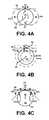
- FIGS. 4A-4Cshow exemplary panning, zooming, and rotating a view of a virtual three-dimensional space
- FIGS. 5A-5Care screen captures of an application startup instructional overlay that may be presented on the graphical user interface
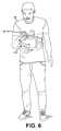
- FIG. 6shows a user providing a motion input to a mobile communications device in accordance with various embodiments of the present disclosure
- FIGS. 7A-7Bare screen captures showing graphical representations of various input strokes
- FIGS. 8A-8Care screen captures showing graphical representations of input strokes corresponding to alphanumeric characters.
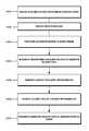
- FIG. 9is a flowchart illustrating the steps of an exemplary method for graphically representing an input stroke corresponding to a motion applied to a sensor device.
- the present disclosurecontemplates various embodiments of capturing motion inputs and generating graphical representations thereof. To this end, apparatuses and methods are disclosed.
- the detailed description set forth below in connection with the appended drawingsis intended as a description of the several presently contemplated embodiments, and is not intended to represent the only form in which the disclosed invention may be developed or utilized.
- the descriptionsets forth the functions and features in connection with the illustrated embodiments. It is to be understood, however, that the same or equivalent functions may be accomplished by different embodiments that are also intended to be encompassed within the scope of the present disclosure. It is further understood that the use of relational terms such as first and second and the like are used solely to distinguish one from another entity without necessarily requiring or implying any actual such relationship or order between such entities.
- FIG. 1illustrates one exemplary mobile device 10 on which various embodiments of the present disclosure may be implemented.
- the mobile device 10may be a smartphone, and therefore include a radio frequency (RF) transceiver 12 that transmits and receives signals via an antenna 42 .
- RFradio frequency
- Conventional devicesare capable of handling multiple wireless communications modes simultaneously. These include several digital phone modalities such as UMTS (Universal Mobile Telecommunications System), 4G LTE (Long Term Evolution), and the like.
- the RF transceiver 12includes a UMTS module 12 a .
- the RF transceiver 12may implement other wireless communications modalities such as WiFi for local area networking and accessing the Internet by way of local area networks, and Bluetooth for linking peripheral devices such as headsets. Accordingly, the RF transceiver may include a WiFi module 12 c and a Bluetooth module 12 d .
- the enumeration of various wireless networking modulesis not intended to be limiting, and others may be included without departing from the scope of the present disclosure.
- the mobile device 10is understood to implement a wide range of functionality through different software applications, which are colloquially known as “apps” in the mobile device context.
- the software applicationsare comprised of pre-programmed instructions that are executed by a central processor 14 and that may be stored on a memory 16 .
- the results of these executed instructionsmay be output for viewing by a user, and the sequence/parameters of those instructions may be modified via inputs from the user.
- the central processor 14interfaces with an input/output subsystem 18 that manages the output functionality of a display 20 and the input functionality of a touch screen 22 and one or more buttons 24 .
- buttons 24may serve a general purpose escape function, while another may serve to power up or power down the mobile device 10 . Additionally, there may be other buttons and switches for controlling volume, limiting haptic entry, and so forth.
- Other smartphone devicesmay include keyboards (not shown) and other mechanical input devices, and the presently disclosed interaction methods with the graphical user interface detailed more fully below are understood to be applicable to such alternative input modalities.
- the mobile device 10includes several other peripheral devices.
- One of the more basicis an audio subsystem 26 with an audio input 28 and an audio output 30 that allows the user to conduct voice telephone calls.
- the audio input 28is connected to a microphone 32 that converts sound to electrical signals, and may include amplifier and ADC (analog to digital converter) circuitry that transforms the continuous analog electrical signals to digital data.
- the audio output 30is connected to a loudspeaker 34 that converts electrical signals to air pressure waves that result in sound, and may likewise include amplifier and DAC (digital to analog converter) circuitry that transforms the digital sound data to a continuous analog electrical signal that drives the loudspeaker 34 .
- the mobile device 10includes a location module 40 , which may be a Global Positioning System (GPS) receiver that is connected to a separate antenna 42 and generates coordinates data of the current location as extrapolated from signals received from the network of GPS satellites.
- GPSGlobal Positioning System
- Motions imparted upon the mobile device 10may be captured as data with a motion subsystem 44 , in particular, with an accelerometer 46 , a gyroscope 48 , and a compass or magnetometer 50 , respectively.
- the accelerometer 46 and the gyroscope 48are three-axis types, that is, three sets of data corresponding to the x, y, and z axes are generated therefrom. Although in some embodiments the accelerometer 46 , the gyroscope 48 , and the magnetometer 50 directly communicate with the central processor 14 , more recent variations of the mobile device 10 utilize the motion subsystem 44 that is embodied as a separate co-processor to which the acceleration and orientation processing is offloaded for greater efficiency and reduced electrical power consumption.
- One exemplary embodiment of the mobile device 10is the Apple iPhone with the M7 motion co-processor.
- the components of the motion subsystem 44may be incorporated into a separate, external device.
- This external devicemay be wearable by the user and communicatively linked to the mobile device 10 over the aforementioned data link modalities.
- the same physical interactions contemplated with the mobile device 10 to invoke various functions as discussed in further detail belowmay be possible with such external wearable device.
- one of the other sensors 52may be a proximity sensor to detect the presence or absence of the user to invoke certain functions, while another may be a light sensor that adjusts the brightness of the display 20 according to ambient light conditions.
- one of the other sensors 52may be a proximity sensor to detect the presence or absence of the user to invoke certain functions, while another may be a light sensor that adjusts the brightness of the display 20 according to ambient light conditions.
- Those having ordinary skill in the artwill recognize that other sensors 52 beyond those considered herein are also possible.
- One embodiment of the present disclosureis directed to an apparatus 54 for generating a graphical representation of a motion input that is applied to one or more sensors.
- the block diagram of FIG. 2illustrates one possible implementation of such apparatus 54 and its foundational components.
- the apparatus 54is understood to correspond generally to the aforementioned mobile device 10 , though this is by way of example only and not of limitation.
- the basic configuration of the apparatus 54may be comprised of a touch input display screen 56 , which may be comprised of the display 20 and the touch screen 22 of the mobile device 10 .
- sensors 58that correspond to the aforementioned accelerometer 46 , gyroscope 48 , and magnetometer 50 .
- the sensors 58are understood to be disposed on a sensor unit, which in most embodiments of the apparatus 54 are integral with the other circuitry of the underlying mobile device 10 .
- the sensor unitmay be disposed on a physically separate circuit, or on a wearable device that is not part of the mobile device 10 and only communicating therewith. Examples of such wearable devices include smart watches that have touch display screens and on-board motion sensors that communicate directly with the mobile device 10 .
- the raw sensor datais provided to a motion input capture module 60 , and is understood to correspond to the spatial motion input applied to the sensor unit.
- the apparatus 54also includes a graphical user interface 62 , which in one embodiment is implemented as a logical module comprised of a series of pre-programmed instructions that can be executed by the central processor 14 of the mobile device 10 . These instructions may collectively make up a standalone application that runs natively on the mobile device 10 , though in other embodiments, it may be a lightweight application that is downloaded to and executed by a web browser running on the mobile communications device.
- the screen capture of FIG. 3shows an embodiment of the graphical user interface 62 , which is generally comprised of a view area 64 for a virtual three-dimensional space 66 .
- the graphical user interface 62is presented within a web browser application interface 68 , which includes the standard interface elements of an address bar 70 , back button 72 a , forward button 72 b , a content share button 74 , a bookmark button 76 , and a window tab button 78 , each of which are understood to invoke corresponding functions of the web browser application that are known in the art.
- a three-axis helper 80When the application is initially loaded, a three-axis helper 80 is displayed in a center region of the view area 64 .
- the three-axis helper 80includes an x-axis indicator 80 x , a y-axis indicator 80 y , and a z-axis indicator 80 z that show the current extent of offset along each of these axes of the view area 64 relative to the virtual three-dimensional space 66 . Additionally, there is a position indicator 82 that is initially centered at an origin point within the virtual three-dimensional space 66 .
- FIGS. 4A-4Cdifferent ways of navigating the virtual three-dimensional space 66 are illustrated. For the sake of simplicity, only a top plan view of the virtual three-dimensional space 66 is depicted. There is a simulated camera 84 that represents a viewport to the virtual three-dimensional space 66 , and the circular regions shown generally correspond to the view area 64 . Thus, in an actual implementation, the view area 64 may be spherical. Furthermore, while the view area 64 is shown with specific boundaries, it is understood that the virtual three-dimensional space 66 will extend further out to infinity. The view area 64 is also characterized by a center point 86 that constitutes the focus point of the camera 84 .
- FIG. 4Aillustrates a panning operation.
- the camera 84is moved along a view plane 88 that is tangent to the circular region constituting the view area 64 .
- the center point 86is understood to move with the view area.
- a circular region 64 ris the view from the camera 84 panned to the right, while a circular region 641 is the view from the camera 84 panned to the left.
- the view area 64is understood to be spherical, so upward and downward panning is also contemplated.
- FIG. 4Billustrates a zooming operation.
- the camera 84remains in the same orientation and in the same position of the view plane 88 , but the view plane 88 is moved closer to and further away from the center point 86 .
- the view area 64may be expanded per circular region 64 a with the camera 84 further away from the center point 86 , while the view area 64 may be narrowed per circular region 64 b with the camera 84 closer to the center point 86 .
- FIG. 4Cillustrates a rotation operation.
- the camera 84is rotated about the center point 86 while the view area 64 remains the same, and the angle of view from the camera 84 to the center point 86 is modified.
- the tangent point of the view plane 88 relative to the view area 64is moved.
- the view plane 88 ais tangent to the circular region corresponding to the view area 64 at point 90 a
- the view plane 88 cis tangent to the circular region corresponding to the view area 64 at a point 90 b .
- the view area 64is understood to be spherical, so upward and downward rotation is possible.
- the foregoing operationsmay be invoked with inputs to the apparatus 54 . More particularly, the panning and zooming operations may be invoked via interactive elements presented on the graphical user interface 62 that are activatable in response to a haptic input upon the touch input display screen 56 .
- there is a zooming joystick 94that can be moved upward and downward to respectively increase and decrease the zoom level or otherwise expand or contract the view are 64 of the virtual three-dimensional space 66 .
- the rotation operationsmay be invoked by imparting a physical rotation motion upon the apparatus 54 .
- the motion input capture module 60receives the data from the sensors 58 , and the view area 64 is adjusted in response.
- the graphical user interface 62is understood to be defined by a virtual space viewing mode and as will be described in further detail below, a brush stroke input mode.
- the panning, zooming, and rotating operationsare accessible when the graphical user interface 62 is in the virtual space viewing mode.
- the view area 64may be reset by activating a view reset button 95 .
- the present disclosurecontemplates the capture of motion imparted to the apparatus 54 or as detected by the sensors 58 , and converting the representative data to a graphical form. This is understood to take place in the brush stroke input mode, which may be invoked by providing a capture initiation command.
- the capture processbegins when a haptic input is received on the touch input display screen on any part of the graphical user interface 62 not corresponding to any displayed interactive elements, e.g., inside the view area 64 .
- the capture processmay continue while the haptic input is being provided, and stops when released.
- the processmay be repeated to input multiple sets of movements.
- an instructional overlay 96may be generated on the graphical user interface 62 .
- an icon representative of the apparatus 54may be shown, together with an instructional text “Press and Hold.”
- a suitable duration of displaying the first segment 96 athere may be a transition to a second segment 96 b in which the icon is animated to indicate movement, along with an instructional text “Move and Draw.”
- a third segment 96 cin which the animation is stopped, and the icon is changed to include a sample captured motion along the lines of what was illustrated in the second segment 96 b , together with an instructional text “Release and View.”
- the foregoing sequencemay be repeated until some input is provided, thereafter transitioning to the display as shown in FIG. 3 without the instructional overlay
- FIG. 7Aillustrates a single stroke path 100 defined by an origin as designated by the position indicator 82 , and ending in a position within the virtual three-dimensional space 66 designated by an ending position indicator 83 .
- FIG. 7Balso illustrates a single stroke path 100 comprised of multiple overlapping segments that corresponds to the apparatus 54 being laterally looped.
- the stroke path 100may be displayed as the motion input is provided, upon completion of the motion input with the detection of the apparatus 54 being stationary, or upon release of the haptic input from the graphical user interface 62 .
- Existing stroke paths 100 in the view area 64may be cleared by activating a reset button 102 .
- the stroke path 100is defined by a plurality of position points within the virtual three-dimensional space 66 , each of which are relative to the starting point or origin.
- the positionis updated based upon the accelerometer 46 , as well as the gyroscope 48 and the magnetometer 50 , in a procedure known in the art as position dead reckoning, as there is no other external source with which the position of the apparatus 54 may be corroborated.
- position dead reckoninga procedure known in the art as position dead reckoning, as there is no other external source with which the position of the apparatus 54 may be corroborated.
- FIGS. 8A-8Cillustrate examples of alphabetic characters being drawn within the virtual three-dimensional space 66 , with FIG.
- FIG. 8Ashowing a stroke path 100 a corresponding to a lower case “a”
- FIG. 8Bshowing a stroke path 100 b corresponding to a lower case “b”
- FIG. 8Cshowing a stroke path 100 c corresponding to a lower case “c.”
- the present disclosurealso contemplates a method for graphically representing the input stroke corresponding to a motion applied to a sensor device, which is generally understood to be the mobile device 10 or the aforementioned apparatus 54 . Accordingly, while the following description will make reference to components such as the accelerometer 46 , the gyroscope 48 , the magnetometer 50 , and the central processor 14 that were specific to the mobile device 10 and/or the apparatus 54 , the method is not limited to implementation thereon. Any other device may be substituted, with component analogues thereof being readily ascertainable by those having ordinary skill in the art.
- the methodcontemplates converting the raw sensor data to quantities that accurately represent, in the aggregate, the actual motion input by the user.
- the methodbegins with a step 1000 of receiving acceleration data from the accelerometer of the sensor device.
- the acceleration datais understood to be referenced to a device frame, and corresponds to the input stroke/motion that is applied to the sensor device.
- the methodproceeds to a step 1002 of transforming the same to a world frame that corresponds to the virtual three-dimensional space 66 .
- Orientation datais utilized for this procedure, and is received from the gyroscope 48 and/or the magnetometer 50 in accordance with a step 1001 that takes place prior to the transformation step 1002 .
- the methodalso includes procedures to minimize this drift, and includes a step 1006 of generating a velocity data drift approximation, and using such value to correct the velocity data in a step 1008 .
- a step 1010 of integrating the corrected velocity datato generate the position points of the input stroke. Again, the position points may be defined relative to the starting point within the virtual three-dimensional space 66 .
- the graphical user interface 62includes a share button 104 which may be activated to invoke content sharing functions that copies the graphic to text message recipients, e-mail recipients, social networking sites, and the like.
Landscapes
- Engineering & Computer Science (AREA)
- Theoretical Computer Science (AREA)
- General Engineering & Computer Science (AREA)
- Human Computer Interaction (AREA)
- Physics & Mathematics (AREA)
- General Physics & Mathematics (AREA)
- Software Systems (AREA)
- User Interface Of Digital Computer (AREA)
Abstract
Description
Claims (23)
Priority Applications (1)
| Application Number | Priority Date | Filing Date | Title |
|---|---|---|---|
| US15/295,907US10437463B2 (en) | 2015-10-16 | 2016-10-17 | Motion-based graphical input system |
Applications Claiming Priority (2)
| Application Number | Priority Date | Filing Date | Title |
|---|---|---|---|
| US201562242947P | 2015-10-16 | 2015-10-16 | |
| US15/295,907US10437463B2 (en) | 2015-10-16 | 2016-10-17 | Motion-based graphical input system |
Publications (2)
| Publication Number | Publication Date |
|---|---|
| US20170109036A1 US20170109036A1 (en) | 2017-04-20 |
| US10437463B2true US10437463B2 (en) | 2019-10-08 |
Family
ID=58523021
Family Applications (1)
| Application Number | Title | Priority Date | Filing Date |
|---|---|---|---|
| US15/295,907Expired - Fee RelatedUS10437463B2 (en) | 2015-10-16 | 2016-10-17 | Motion-based graphical input system |
Country Status (1)
| Country | Link |
|---|---|
| US (1) | US10437463B2 (en) |
Citations (48)
| Publication number | Priority date | Publication date | Assignee | Title |
|---|---|---|---|---|
| US5534917A (en) | 1991-05-09 | 1996-07-09 | Very Vivid, Inc. | Video image based control system |
| WO2002039063A1 (en) | 2000-11-08 | 2002-05-16 | Nira Dynamics Ab | Map-aided positioning |
| US20050238201A1 (en) | 2004-04-15 | 2005-10-27 | Atid Shamaie | Tracking bimanual movements |
| US7058204B2 (en) | 2000-10-03 | 2006-06-06 | Gesturetek, Inc. | Multiple camera control system |
| US20070090180A1 (en) | 2003-04-09 | 2007-04-26 | Griffis Andrew J | Machine vision system for enterprise management |
| US7227526B2 (en) | 2000-07-24 | 2007-06-05 | Gesturetek, Inc. | Video-based image control system |
| US20070136132A1 (en) | 2005-12-09 | 2007-06-14 | Envisionit Llc | Systems and methods for distributing promotions over message broadcasting and local wireless systems |
| US7379566B2 (en) | 2005-01-07 | 2008-05-27 | Gesturetek, Inc. | Optical flow based tilt sensor |
| US20080147493A1 (en) | 2006-10-23 | 2008-06-19 | Ari Aarnio | Ad presentment in a mobile device |
| US7389591B2 (en) | 2005-05-17 | 2008-06-24 | Gesturetek, Inc. | Orientation-sensitive signal output |
| US20090029720A1 (en) | 2007-07-27 | 2009-01-29 | Yahoo! Inc. | System and method for providing electronic advertisements |
| US20090157341A1 (en) | 2007-04-17 | 2009-06-18 | Schlumberger Technology Corporation | Methods of Correcting Accelerometer and Magnetometer Measurements |
| US20090184849A1 (en) | 2008-01-18 | 2009-07-23 | Invensense, Inc. | Interfacing application programs and motion sensors of a device |
| US20090319166A1 (en) | 2008-06-20 | 2009-12-24 | Microsoft Corporation | Mobile computing services based on devices with dynamic direction information |
| US20100114562A1 (en) | 2006-11-03 | 2010-05-06 | Appen Pty Limited | Document processor and associated method |
| US20100257475A1 (en) | 2009-04-07 | 2010-10-07 | Qualcomm Incorporated | System and method for providing multiple user interfaces |
| US20100269030A1 (en) | 2009-04-17 | 2010-10-21 | Jokaroo Entertainment Inc. | Method and device for temporally displaying advertising content on a webpage |
| US20110173204A1 (en) | 2010-01-08 | 2011-07-14 | Microsoft Corporation | Assigning gesture dictionaries |
| US20110191024A1 (en) | 2010-01-29 | 2011-08-04 | Research In Motion Limited | Portable mobile transceiver for gps navigation and vehicle data input for dead reckoning mode |
| US20110238308A1 (en) | 2010-03-26 | 2011-09-29 | Isaac Thomas Miller | Pedal navigation using leo signals and body-mounted sensors |
| US20110270679A1 (en) | 2010-04-29 | 2011-11-03 | Research In Motion Limited | System and method for distributing messages to an electronic device based on movement of the device |
| US20110288913A1 (en) | 2010-05-20 | 2011-11-24 | Google Inc. | Interactive Ads |
| US20120036003A1 (en) | 2010-08-06 | 2012-02-09 | Linda Tong | System and method for rewarding application actions |
| US20120041767A1 (en) | 2010-08-11 | 2012-02-16 | Nike Inc. | Athletic Activity User Experience and Environment |
| US20120131454A1 (en) | 2010-11-24 | 2012-05-24 | Siddharth Shah | Activating an advertisement by performing gestures on the advertisement |
| US20120246596A1 (en) | 2011-02-21 | 2012-09-27 | Bas Ording | Managing Workspaces in a User Interface |
| US20120265595A1 (en) | 2011-04-14 | 2012-10-18 | Fiksu, Inc. | Mobile digital media download incentive management through multiple user action tracking |
| US20120310717A1 (en) | 2011-05-31 | 2012-12-06 | Nokia Corporation | Method and apparatus for controlling a perspective display of advertisements using sensor data |
| US20130166397A1 (en) | 2011-12-26 | 2013-06-27 | Nhn Business Platform Corporation | System and method for providing advertisement based on motion of mobile terminal |
| US20130211923A1 (en) | 2012-02-10 | 2013-08-15 | Cameron Yuill | Sensor-based interactive advertisement |
| US20130211924A1 (en) | 2012-02-10 | 2013-08-15 | Cameron Yuill | System and method for generating sensor-based advertisements |
| US20130218680A1 (en) | 2012-02-18 | 2013-08-22 | Nils Forsblom | Location sensitive advertisement delivery and presentation |
| US8631358B2 (en) | 2007-10-10 | 2014-01-14 | Apple Inc. | Variable device graphical user interface |
| US20140023087A1 (en) | 2012-07-17 | 2014-01-23 | Qualcomm Incorporated | Concurrent data streaming using various parameters from the same sensor |
| US20140280517A1 (en) | 2013-03-15 | 2014-09-18 | Foresee Results, Inc. | System and Method for Capturing Interaction Data Relating to a Host Application |
| US20140282088A1 (en) | 2013-03-13 | 2014-09-18 | Vdopia, Inc | Method and apparatus for sharing, interacting and responding to advertising |
| US20140278853A1 (en) | 2013-03-13 | 2014-09-18 | Tapjoy, Inc. | Extrinsic incentivized scaffolding in computer games via advertising responsive to intrinsic game events |
| US20140288873A1 (en) | 2013-03-22 | 2014-09-25 | Qualcomm Incorporated | Pre-processing inertial sensor measurements for navigation |
| US20140316884A1 (en) | 2013-04-22 | 2014-10-23 | Yahoo! Inc. | Interactive advertising system |
| US20140344055A1 (en) | 2013-05-17 | 2014-11-20 | Apple Inc. | Interaction-aware advertising for minimizing banner blindness |
| US20140352400A1 (en) | 2013-05-29 | 2014-12-04 | Freescale Semiconductor, Inc. | Transducer-including devices, and methods and apparatus for their calibration |
| US20150046247A1 (en) | 2013-08-07 | 2015-02-12 | Zynga Inc. | Methods and Systems for Computer Application Incentivization Based on Reduced Advertisement |
| US20150081448A1 (en) | 2013-09-16 | 2015-03-19 | Microsoft Corporation | Non-intrusive advertisement management |
| US20150095160A1 (en) | 2013-10-01 | 2015-04-02 | Paschar Llc | Method and system for providing advertising on mobile devices |
| US20150120458A1 (en) | 2013-04-30 | 2015-04-30 | Buzzvil Co., Ltd. | Advertising system and method using in-app advertisement module |
| US20150286279A1 (en) | 2014-04-07 | 2015-10-08 | InvenSense, Incorporated | Systems and methods for guiding a user during calibration of a sensor |
| US9299092B1 (en) | 2013-10-15 | 2016-03-29 | Tapjoy, Inc. | Selection of ad units of a compound advertisement for display |
| US20160292742A1 (en) | 2015-04-02 | 2016-10-06 | Vungle, Inc. | Systems and methods for dynamic ad selection of multiple ads or ad campaigns on devices |
- 2016
- 2016-10-17USUS15/295,907patent/US10437463B2/ennot_activeExpired - Fee Related
Patent Citations (48)
| Publication number | Priority date | Publication date | Assignee | Title |
|---|---|---|---|---|
| US5534917A (en) | 1991-05-09 | 1996-07-09 | Very Vivid, Inc. | Video image based control system |
| US7227526B2 (en) | 2000-07-24 | 2007-06-05 | Gesturetek, Inc. | Video-based image control system |
| US7058204B2 (en) | 2000-10-03 | 2006-06-06 | Gesturetek, Inc. | Multiple camera control system |
| WO2002039063A1 (en) | 2000-11-08 | 2002-05-16 | Nira Dynamics Ab | Map-aided positioning |
| US20070090180A1 (en) | 2003-04-09 | 2007-04-26 | Griffis Andrew J | Machine vision system for enterprise management |
| US20050238201A1 (en) | 2004-04-15 | 2005-10-27 | Atid Shamaie | Tracking bimanual movements |
| US7379566B2 (en) | 2005-01-07 | 2008-05-27 | Gesturetek, Inc. | Optical flow based tilt sensor |
| US7389591B2 (en) | 2005-05-17 | 2008-06-24 | Gesturetek, Inc. | Orientation-sensitive signal output |
| US20070136132A1 (en) | 2005-12-09 | 2007-06-14 | Envisionit Llc | Systems and methods for distributing promotions over message broadcasting and local wireless systems |
| US20080147493A1 (en) | 2006-10-23 | 2008-06-19 | Ari Aarnio | Ad presentment in a mobile device |
| US20100114562A1 (en) | 2006-11-03 | 2010-05-06 | Appen Pty Limited | Document processor and associated method |
| US20090157341A1 (en) | 2007-04-17 | 2009-06-18 | Schlumberger Technology Corporation | Methods of Correcting Accelerometer and Magnetometer Measurements |
| US20090029720A1 (en) | 2007-07-27 | 2009-01-29 | Yahoo! Inc. | System and method for providing electronic advertisements |
| US8631358B2 (en) | 2007-10-10 | 2014-01-14 | Apple Inc. | Variable device graphical user interface |
| US20090184849A1 (en) | 2008-01-18 | 2009-07-23 | Invensense, Inc. | Interfacing application programs and motion sensors of a device |
| US20090319166A1 (en) | 2008-06-20 | 2009-12-24 | Microsoft Corporation | Mobile computing services based on devices with dynamic direction information |
| US20100257475A1 (en) | 2009-04-07 | 2010-10-07 | Qualcomm Incorporated | System and method for providing multiple user interfaces |
| US20100269030A1 (en) | 2009-04-17 | 2010-10-21 | Jokaroo Entertainment Inc. | Method and device for temporally displaying advertising content on a webpage |
| US20110173204A1 (en) | 2010-01-08 | 2011-07-14 | Microsoft Corporation | Assigning gesture dictionaries |
| US20110191024A1 (en) | 2010-01-29 | 2011-08-04 | Research In Motion Limited | Portable mobile transceiver for gps navigation and vehicle data input for dead reckoning mode |
| US20110238308A1 (en) | 2010-03-26 | 2011-09-29 | Isaac Thomas Miller | Pedal navigation using leo signals and body-mounted sensors |
| US20110270679A1 (en) | 2010-04-29 | 2011-11-03 | Research In Motion Limited | System and method for distributing messages to an electronic device based on movement of the device |
| US20110288913A1 (en) | 2010-05-20 | 2011-11-24 | Google Inc. | Interactive Ads |
| US20120036003A1 (en) | 2010-08-06 | 2012-02-09 | Linda Tong | System and method for rewarding application actions |
| US20120041767A1 (en) | 2010-08-11 | 2012-02-16 | Nike Inc. | Athletic Activity User Experience and Environment |
| US20120131454A1 (en) | 2010-11-24 | 2012-05-24 | Siddharth Shah | Activating an advertisement by performing gestures on the advertisement |
| US20120246596A1 (en) | 2011-02-21 | 2012-09-27 | Bas Ording | Managing Workspaces in a User Interface |
| US20120265595A1 (en) | 2011-04-14 | 2012-10-18 | Fiksu, Inc. | Mobile digital media download incentive management through multiple user action tracking |
| US20120310717A1 (en) | 2011-05-31 | 2012-12-06 | Nokia Corporation | Method and apparatus for controlling a perspective display of advertisements using sensor data |
| US20130166397A1 (en) | 2011-12-26 | 2013-06-27 | Nhn Business Platform Corporation | System and method for providing advertisement based on motion of mobile terminal |
| US20130211923A1 (en) | 2012-02-10 | 2013-08-15 | Cameron Yuill | Sensor-based interactive advertisement |
| US20130211924A1 (en) | 2012-02-10 | 2013-08-15 | Cameron Yuill | System and method for generating sensor-based advertisements |
| US20130218680A1 (en) | 2012-02-18 | 2013-08-22 | Nils Forsblom | Location sensitive advertisement delivery and presentation |
| US20140023087A1 (en) | 2012-07-17 | 2014-01-23 | Qualcomm Incorporated | Concurrent data streaming using various parameters from the same sensor |
| US20140278853A1 (en) | 2013-03-13 | 2014-09-18 | Tapjoy, Inc. | Extrinsic incentivized scaffolding in computer games via advertising responsive to intrinsic game events |
| US20140282088A1 (en) | 2013-03-13 | 2014-09-18 | Vdopia, Inc | Method and apparatus for sharing, interacting and responding to advertising |
| US20140280517A1 (en) | 2013-03-15 | 2014-09-18 | Foresee Results, Inc. | System and Method for Capturing Interaction Data Relating to a Host Application |
| US20140288873A1 (en) | 2013-03-22 | 2014-09-25 | Qualcomm Incorporated | Pre-processing inertial sensor measurements for navigation |
| US20140316884A1 (en) | 2013-04-22 | 2014-10-23 | Yahoo! Inc. | Interactive advertising system |
| US20150120458A1 (en) | 2013-04-30 | 2015-04-30 | Buzzvil Co., Ltd. | Advertising system and method using in-app advertisement module |
| US20140344055A1 (en) | 2013-05-17 | 2014-11-20 | Apple Inc. | Interaction-aware advertising for minimizing banner blindness |
| US20140352400A1 (en) | 2013-05-29 | 2014-12-04 | Freescale Semiconductor, Inc. | Transducer-including devices, and methods and apparatus for their calibration |
| US20150046247A1 (en) | 2013-08-07 | 2015-02-12 | Zynga Inc. | Methods and Systems for Computer Application Incentivization Based on Reduced Advertisement |
| US20150081448A1 (en) | 2013-09-16 | 2015-03-19 | Microsoft Corporation | Non-intrusive advertisement management |
| US20150095160A1 (en) | 2013-10-01 | 2015-04-02 | Paschar Llc | Method and system for providing advertising on mobile devices |
| US9299092B1 (en) | 2013-10-15 | 2016-03-29 | Tapjoy, Inc. | Selection of ad units of a compound advertisement for display |
| US20150286279A1 (en) | 2014-04-07 | 2015-10-08 | InvenSense, Incorporated | Systems and methods for guiding a user during calibration of a sensor |
| US20160292742A1 (en) | 2015-04-02 | 2016-10-06 | Vungle, Inc. | Systems and methods for dynamic ad selection of multiple ads or ad campaigns on devices |
Non-Patent Citations (12)
| Title |
|---|
| Canadian Trademark Registration No. TMA700194; Registered Nov. 6, 2007; Owned by Qualcomm Incorporated. |
| Chris Brandrick, Apple's M7 Chip Is the Trojan Horse for Its Wearable Computing Plans, Sep. 13, 2013, 7 Pages. |
| David Talbot, What Apple's M7 Motion-Sensing Chip Could Do, Sep. 25, 2013, 2 Pages. |
| Forbes, Shaking Up Advertising, web page, http://www.forbes.com/2009/03/16dockersmobileadvertisingleadershipcmonetworkmobilemarketing.Html, Mar. 16, 2009, 4 pages. |
| International Search Report and Written Opinion for International Application No. PCT/US2016/044318; dated Oct. 7, 2016; 12 pages. |
| International Search Report and Written Opinion for PCT/US14/69554; dated Mar. 6, 2015; 11 pages. |
| Leadbolt, LeadBolt Launches Industry's First and Only Mobile Ad Format to Utilize Gyroscope Technology, web page, http://www.businesswire.com/news/home/20131217005561/en/LeadBolt-Launches-Industry%E2%80%99s-Mobile-Ad-Format-Utilize, Dec. 17, 2013, 2 pages. |
| Medialets, Medialets Shakes Up Mobile Advertising, web page, https://www.medialets.com/medialetsshakesupmobileadvertising/, Apr. 22, 2009, 3 pages. |
| Medialets, World's First Shakable Ad™ by Medialets, video, https://www.youtube.com/watch?v=NwnuwGhcpRU, uploaded Apr. 11, 2009, 2 pages. |
| Olive Media Canada, Infiniti JX Tablet Advertisement by Olive Mobile, video, https://www.youtube.com/watch? v=KGIWebpdmYE#t=79, published May 29, 2012, 2 pages. |
| Rachel Lamb, Infiniti releases first touch-screen ad for JX, web page, http://www.luxurydaily.com/infinitireleasesfirsttouchscreenadforxj/, Jun. 7, 2012, 4 pages. |
| Rebecca Borison, Tic Tac sees 7.94pc engagement rate with richmedia ad, web page, http://www.mobilemarketer.com/cms/news/advertising/16631.html, Nov. 19, 2013, 4 pages. |
Also Published As
| Publication number | Publication date |
|---|---|
| US20170109036A1 (en) | 2017-04-20 |
Similar Documents
| Publication | Publication Date | Title |
|---|---|---|
| US10318011B2 (en) | Gesture-controlled augmented reality experience using a mobile communications device | |
| CN108495029B (en) | A kind of photographing method and mobile terminal | |
| US9794495B1 (en) | Multiple streaming camera navigation interface system | |
| CN109828732B (en) | A display control method and terminal device | |
| US10451648B2 (en) | Sensor control switch | |
| CN109032486B (en) | Display control method and terminal equipment | |
| CN110658971B (en) | Screen capture method and terminal device | |
| US20170269712A1 (en) | Immersive virtual experience using a mobile communication device | |
| JP2021531589A (en) | Motion recognition method, device and electronic device for target | |
| CN108763317B (en) | A kind of method and terminal device for assisting selection of pictures | |
| CN111010512A (en) | Display control method and electronic equipment | |
| CN108920069B (en) | Touch operation method and device, mobile terminal and storage medium | |
| US20140320537A1 (en) | Method, device and storage medium for controlling electronic map | |
| US20180253161A1 (en) | Spatial motion-based user interactivity | |
| CN110944139A (en) | A display control method and electronic device | |
| CN108833791B (en) | A shooting method and device | |
| US9665232B2 (en) | Information-processing device, storage medium, information-processing method, and information-processing system for enlarging or reducing an image displayed on a display device | |
| US20190212834A1 (en) | Software gyroscope apparatus | |
| US10437463B2 (en) | Motion-based graphical input system | |
| CN108008875B (en) | Method for controlling cursor movement and terminal equipment | |
| CN107077276B (en) | Method and apparatus for providing a user interface | |
| CN109491561B (en) | Image display method and terminal | |
| JP2023134340A (en) | Program, information processing device and method |
Legal Events
| Date | Code | Title | Description |
|---|---|---|---|
| AS | Assignment | Owner name:NILS FORSBLOM TRUST, CALIFORNIA Free format text:ASSIGNMENT OF ASSIGNORS INTEREST;ASSIGNOR:ADTILE TECHNOLOGIES INC.;REEL/FRAME:048441/0211 Effective date:20190201 Owner name:LUMINI CORPORATION, CALIFORNIA Free format text:ASSIGNMENT OF ASSIGNORS INTEREST;ASSIGNOR:NILS FORSBLOM TRUST;REEL/FRAME:048444/0719 Effective date:20190226 | |
| STPP | Information on status: patent application and granting procedure in general | Free format text:DOCKETED NEW CASE - READY FOR EXAMINATION | |
| AS | Assignment | Owner name:ADTILE TECHNOLOGIES INC., CALIFORNIA Free format text:ASSIGNMENT OF ASSIGNORS INTEREST;ASSIGNORS:FORSBLOM, NILS;SCANDALIATO, ANGELO;METTI, MAXIMILIAN;AND OTHERS;REEL/FRAME:048782/0739 Effective date:20170301 | |
| STPP | Information on status: patent application and granting procedure in general | Free format text:NOTICE OF ALLOWANCE MAILED -- APPLICATION RECEIVED IN OFFICE OF PUBLICATIONS | |
| STPP | Information on status: patent application and granting procedure in general | Free format text:PUBLICATIONS -- ISSUE FEE PAYMENT VERIFIED | |
| STCF | Information on status: patent grant | Free format text:PATENTED CASE | |
| FEPP | Fee payment procedure | Free format text:MAINTENANCE FEE REMINDER MAILED (ORIGINAL EVENT CODE: REM.); ENTITY STATUS OF PATENT OWNER: SMALL ENTITY | |
| LAPS | Lapse for failure to pay maintenance fees | Free format text:PATENT EXPIRED FOR FAILURE TO PAY MAINTENANCE FEES (ORIGINAL EVENT CODE: EXP.); ENTITY STATUS OF PATENT OWNER: SMALL ENTITY | |
| STCH | Information on status: patent discontinuation | Free format text:PATENT EXPIRED DUE TO NONPAYMENT OF MAINTENANCE FEES UNDER 37 CFR 1.362 | |
| FP | Lapsed due to failure to pay maintenance fee | Effective date:20231008 |