US10437400B2 - Touch input device - Google Patents
Touch input deviceDownload PDFInfo
- Publication number
- US10437400B2 US10437400B2US15/795,446US201715795446AUS10437400B2US 10437400 B2US10437400 B2US 10437400B2US 201715795446 AUS201715795446 AUS 201715795446AUS 10437400 B2US10437400 B2US 10437400B2
- Authority
- US
- United States
- Prior art keywords
- touch
- guide
- touch button
- input device
- support body
- Prior art date
- Legal status (The legal status is an assumption and is not a legal conclusion. Google has not performed a legal analysis and makes no representation as to the accuracy of the status listed.)
- Active, expires
Links
Images


Classifications
- G—PHYSICS
- G06—COMPUTING OR CALCULATING; COUNTING
- G06F—ELECTRIC DIGITAL DATA PROCESSING
- G06F3/00—Input arrangements for transferring data to be processed into a form capable of being handled by the computer; Output arrangements for transferring data from processing unit to output unit, e.g. interface arrangements
- G06F3/01—Input arrangements or combined input and output arrangements for interaction between user and computer
- G06F3/03—Arrangements for converting the position or the displacement of a member into a coded form
- G06F3/041—Digitisers, e.g. for touch screens or touch pads, characterised by the transducing means
- G06F3/0414—Digitisers, e.g. for touch screens or touch pads, characterised by the transducing means using force sensing means to determine a position
- G—PHYSICS
- G06—COMPUTING OR CALCULATING; COUNTING
- G06F—ELECTRIC DIGITAL DATA PROCESSING
- G06F3/00—Input arrangements for transferring data to be processed into a form capable of being handled by the computer; Output arrangements for transferring data from processing unit to output unit, e.g. interface arrangements
- G06F3/01—Input arrangements or combined input and output arrangements for interaction between user and computer
- G06F3/03—Arrangements for converting the position or the displacement of a member into a coded form
- G06F3/041—Digitisers, e.g. for touch screens or touch pads, characterised by the transducing means
- G06F3/044—Digitisers, e.g. for touch screens or touch pads, characterised by the transducing means by capacitive means
- B—PERFORMING OPERATIONS; TRANSPORTING
- B60—VEHICLES IN GENERAL
- B60K—ARRANGEMENT OR MOUNTING OF PROPULSION UNITS OR OF TRANSMISSIONS IN VEHICLES; ARRANGEMENT OR MOUNTING OF PLURAL DIVERSE PRIME-MOVERS IN VEHICLES; AUXILIARY DRIVES FOR VEHICLES; INSTRUMENTATION OR DASHBOARDS FOR VEHICLES; ARRANGEMENTS IN CONNECTION WITH COOLING, AIR INTAKE, GAS EXHAUST OR FUEL SUPPLY OF PROPULSION UNITS IN VEHICLES
- B60K35/00—Instruments specially adapted for vehicles; Arrangement of instruments in or on vehicles
- B60K35/10—Input arrangements, i.e. from user to vehicle, associated with vehicle functions or specially adapted therefor
- B60K37/06—
- G—PHYSICS
- G06—COMPUTING OR CALCULATING; COUNTING
- G06F—ELECTRIC DIGITAL DATA PROCESSING
- G06F3/00—Input arrangements for transferring data to be processed into a form capable of being handled by the computer; Output arrangements for transferring data from processing unit to output unit, e.g. interface arrangements
- G06F3/01—Input arrangements or combined input and output arrangements for interaction between user and computer
- G06F3/02—Input arrangements using manually operated switches, e.g. using keyboards or dials
- G06F3/0202—Constructional details or processes of manufacture of the input device
- G—PHYSICS
- G06—COMPUTING OR CALCULATING; COUNTING
- G06F—ELECTRIC DIGITAL DATA PROCESSING
- G06F3/00—Input arrangements for transferring data to be processed into a form capable of being handled by the computer; Output arrangements for transferring data from processing unit to output unit, e.g. interface arrangements
- G06F3/01—Input arrangements or combined input and output arrangements for interaction between user and computer
- G06F3/03—Arrangements for converting the position or the displacement of a member into a coded form
- G06F3/033—Pointing devices displaced or positioned by the user, e.g. mice, trackballs, pens or joysticks; Accessories therefor
- G06F3/039—Accessories therefor, e.g. mouse pads
- G06F3/0393—Accessories for touch pads or touch screens, e.g. mechanical guides added to touch screens for drawing straight lines, hard keys overlaying touch screens or touch pads
- G—PHYSICS
- G06—COMPUTING OR CALCULATING; COUNTING
- G06F—ELECTRIC DIGITAL DATA PROCESSING
- G06F3/00—Input arrangements for transferring data to be processed into a form capable of being handled by the computer; Output arrangements for transferring data from processing unit to output unit, e.g. interface arrangements
- G06F3/01—Input arrangements or combined input and output arrangements for interaction between user and computer
- G06F3/03—Arrangements for converting the position or the displacement of a member into a coded form
- G06F3/041—Digitisers, e.g. for touch screens or touch pads, characterised by the transducing means
- G06F3/044—Digitisers, e.g. for touch screens or touch pads, characterised by the transducing means by capacitive means
- G06F3/0448—Details of the electrode shape, e.g. for enhancing the detection of touches, for generating specific electric field shapes, for enhancing display quality
- H—ELECTRICITY
- H01—ELECTRIC ELEMENTS
- H01H—ELECTRIC SWITCHES; RELAYS; SELECTORS; EMERGENCY PROTECTIVE DEVICES
- H01H13/00—Switches having rectilinearly-movable operating part or parts adapted for pushing or pulling in one direction only, e.g. push-button switch
- H01H13/02—Details
- H01H13/12—Movable parts; Contacts mounted thereon
- H01H13/14—Operating parts, e.g. push-button
- H—ELECTRICITY
- H01—ELECTRIC ELEMENTS
- H01H—ELECTRIC SWITCHES; RELAYS; SELECTORS; EMERGENCY PROTECTIVE DEVICES
- H01H13/00—Switches having rectilinearly-movable operating part or parts adapted for pushing or pulling in one direction only, e.g. push-button switch
- H01H13/02—Details
- H01H13/26—Snap-action arrangements depending upon deformation of elastic members
- H01H13/28—Snap-action arrangements depending upon deformation of elastic members using compression or extension of coil springs
- H—ELECTRICITY
- H03—ELECTRONIC CIRCUITRY
- H03K—PULSE TECHNIQUE
- H03K17/00—Electronic switching or gating, i.e. not by contact-making and –breaking
- H03K17/94—Electronic switching or gating, i.e. not by contact-making and –breaking characterised by the way in which the control signals are generated
- H03K17/945—Proximity switches
- H03K17/955—Proximity switches using a capacitive detector
- B60K2370/143—
- B60K2370/40—
- G—PHYSICS
- G06—COMPUTING OR CALCULATING; COUNTING
- G06F—ELECTRIC DIGITAL DATA PROCESSING
- G06F2203/00—Indexing scheme relating to G06F3/00 - G06F3/048
- G06F2203/041—Indexing scheme relating to G06F3/041 - G06F3/045
- G06F2203/04101—2.5D-digitiser, i.e. digitiser detecting the X/Y position of the input means, finger or stylus, also when it does not touch, but is proximate to the digitiser's interaction surface and also measures the distance of the input means within a short range in the Z direction, possibly with a separate measurement setup
- G—PHYSICS
- G06—COMPUTING OR CALCULATING; COUNTING
- G06F—ELECTRIC DIGITAL DATA PROCESSING
- G06F2203/00—Indexing scheme relating to G06F3/00 - G06F3/048
- G06F2203/041—Indexing scheme relating to G06F3/041 - G06F3/045
- G06F2203/04105—Pressure sensors for measuring the pressure or force exerted on the touch surface without providing the touch position
- G—PHYSICS
- G06—COMPUTING OR CALCULATING; COUNTING
- G06F—ELECTRIC DIGITAL DATA PROCESSING
- G06F3/00—Input arrangements for transferring data to be processed into a form capable of being handled by the computer; Output arrangements for transferring data from processing unit to output unit, e.g. interface arrangements
- G06F3/01—Input arrangements or combined input and output arrangements for interaction between user and computer
- G06F3/02—Input arrangements using manually operated switches, e.g. using keyboards or dials
- G06F3/0202—Constructional details or processes of manufacture of the input device
- G06F3/0224—Key guide holders
- G—PHYSICS
- G06—COMPUTING OR CALCULATING; COUNTING
- G06F—ELECTRIC DIGITAL DATA PROCESSING
- G06F3/00—Input arrangements for transferring data to be processed into a form capable of being handled by the computer; Output arrangements for transferring data from processing unit to output unit, e.g. interface arrangements
- G06F3/01—Input arrangements or combined input and output arrangements for interaction between user and computer
- G06F3/03—Arrangements for converting the position or the displacement of a member into a coded form
- G06F3/041—Digitisers, e.g. for touch screens or touch pads, characterised by the transducing means
- H—ELECTRICITY
- H01—ELECTRIC ELEMENTS
- H01K—ELECTRIC INCANDESCENT LAMPS
- H01K13/00—Lamps having an incandescent body which is substantially non-conductive until heated, e.g. Nernst lamp
- H01K13/02—Heating arrangements
- H01K13/04—Heating arrangements using electric discharge
- H—ELECTRICITY
- H03—ELECTRONIC CIRCUITRY
- H03K—PULSE TECHNIQUE
- H03K17/00—Electronic switching or gating, i.e. not by contact-making and –breaking
- H03K17/94—Electronic switching or gating, i.e. not by contact-making and –breaking characterised by the way in which the control signals are generated
- H03K17/96—Touch switches
- H03K17/962—Capacitive touch switches
- H03K17/9622—Capacitive touch switches using a plurality of detectors, e.g. keyboard
- H—ELECTRICITY
- H03—ELECTRONIC CIRCUITRY
- H03K—PULSE TECHNIQUE
- H03K17/00—Electronic switching or gating, i.e. not by contact-making and –breaking
- H03K17/94—Electronic switching or gating, i.e. not by contact-making and –breaking characterised by the way in which the control signals are generated
- H03K17/96—Touch switches
- H03K17/9625—Touch switches using a force resistance transducer
- H—ELECTRICITY
- H03—ELECTRONIC CIRCUITRY
- H03K—PULSE TECHNIQUE
- H03K2217/00—Indexing scheme related to electronic switching or gating, i.e. not by contact-making or -breaking covered by H03K17/00
- H03K2217/94—Indexing scheme related to electronic switching or gating, i.e. not by contact-making or -breaking covered by H03K17/00 characterised by the way in which the control signal is generated
- H03K2217/96—Touch switches
- H03K2217/96054—Double function: touch detection combined with detection of a movable element
Definitions
- the present disclosurerelates to a touch input device, and more particularly, to a touch input device capable of improving blind control and usability of the touch input device by detachably mounting a mechanical operating unit on a surface of a touch sensing element.
- a touch input devicefor example, a touch screen or a touch pad
- a touch input deviceis configured to sense a touch by a pointing object (a finger of a user, a stylus tip, and the like), and to determine the characteristics (strength of power, a touch location, a moving direction, and the like) of the touch by the pointing object.
- Such an input deviceincludes various types of input devices such as a resistive-based touch input device, a capacitance-based touch input device, a force-based touch input device, an infrared-based touch input device, and a surface acoustic wave-based touch input device.
- a resistive-based touch input devicesuch as a resistive-based touch input device, a capacitance-based touch input device, a force-based touch input device, an infrared-based touch input device, and a surface acoustic wave-based touch input device.
- Touch input devicesmay be applied to various fields, and include a computer display device, a cash dispenser automation device, a mobile terminal, a touch pad of a notebook, a touch input unit for a vehicle, and the like.
- a touch input devicewhich is applied to a touch input unit for a vehicle, typically employs a capacitive touchpad.
- a capacitive touchpadsince touch areas are not mechanically partitioned, operations may be erroneously performed.
- the capacitive touch padmay not perform blind control, and may lack physical operability, intuitive manipulation, and affordance. Accordingly, user convenience may be degraded by use of the capacitive touchpad.
- An aspect of the present disclosureprovides a touch input device capable of not only performing blind control, but improving user convenience by detachably mounting a mechanical operating unit, which provides physical operability, on a touch sensing element.
- a touch input devicemay include a touch sensing element that senses a touch, and a mechanical operating unit detachably mounted on the touch sensing element.
- the mechanical operating unitmay have at least one touch button movable in a vertical direction and a support body that supports the touch button.
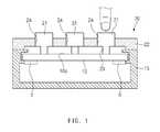
- FIG. 1is a schematic sectional view illustrating a touch input device, according to an embodiment of the disclosure
- FIG. 2is a sectional view illustrating a mechanical operating unit of the touch input device, according to an embodiment of the present disclosure
- FIG. 3is a sectional view illustrating a mechanical operating unit of a touch input device, according to another embodiment of the present disclosure
- FIG. 4is a sectional view illustrating a mechanical operating unit of a touch input device, according to another embodiment of the present disclosure
- FIG. 5is a sectional view illustrating a mechanical operating unit of a touch input device, according to another embodiment of the present disclosure
- FIG. 6is a sectional view illustrating a mechanical operating unit of a touch input device, according to another embodiment of the present disclosure.
- FIG. 7is a sectional view illustrating a mechanical operating unit of a touch input device, according to another embodiment of the present disclosure.
- FIG. 8is a sectional view illustrating a mechanical operating unit of a touch input device, according to another embodiment of the present disclosure.
- FIG. 9is a sectional view illustrating a mechanical operating unit of a touch input device, according to another embodiment of the present disclosure.
- FIG. 10is a sectional view illustrating a mechanical operating unit of a touch input device, according to another embodiment of the present disclosure.
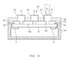
- FIG. 11is a schematic sectional view illustrating the state that the mechanical operating unit of the touch input device is assembled with a case, according to an embodiment of the present disclosure
- FIG. 12is a sectional view illustrating the state that the mechanical operating unit of the touch input device is assembled with a case, according to an embodiment of the present disclosure
- FIG. 13is a sectional view illustrating the state that the mechanical operating unit of the touch input device is assembled with a case, according to another embodiment of the present disclosure.
- FIG. 14is a sectional view illustrating the state that the mechanical operating unit of the touch input device is assembled with a case, according to another embodiment of the present disclosure.
- vehicleor “vehicular” or other similar term as used herein is inclusive of motor vehicles in general such as passenger automobiles including sports utility vehicles (SUV), buses, trucks, various commercial vehicles, watercraft including a variety of boats and ships, aircraft, and the like, and includes hybrid vehicles, electric vehicles, plug-in hybrid electric vehicles, hydrogen-powered vehicles and other alternative fuel vehicles (e.g. fuels derived from resources other than petroleum).
- a hybrid vehicleis a vehicle that has two or more sources of power, for example both gasoline-powered and electric-powered vehicles.
- control logic of the present disclosuremay be embodied as non-transitory computer readable media on a computer readable medium containing executable program instructions executed by a processor, controller or the like.
- Examples of computer readable mediainclude, but are not limited to, ROM, RAM, compact disc (CD)-ROMs, magnetic tapes, floppy disks, flash drives, smart cards and optical data storage devices.
- the computer readable mediumcan also be distributed in network coupled computer systems so that the computer readable media is stored and executed in a distributed fashion, e.g., by a telematics server or a Controller Area Network (CAN).
- a telematics serveror a Controller Area Network (CAN).
- CANController Area Network
- a touch input devicemay include a touch sensing element 10 which senses a touch.
- the touch sensing element 10may be formed in a plate structure, and may have a top surface serving as a touch surface 10 a .
- the touch surface 10 amay be formed in a flat structure extending in a horizontal direction, or may be formed in a partially curved structure on the horizontal surface.
- the touch sensing element 10may have edges fixedly mounted into a case 15 , and thus may be stably supported by the case 15 .
- a plurality of force sensors 5may be mounted on a bottom surface of the touch sensing element 10 .
- the touch sensing element 10may be realized in a force-based touch input structure due to the force sensors 5 .
- the force sensors 5may be coupled to the touch sensing element 10 .
- the force sensors 5may be mounted on the bottom surface of the touch sensing element 10 , which corresponds to an opposite surface to the touch surface 10 a .
- the force sensor 5may be a strain gauge or an electrostatic force sensor.
- a mechanical operating unit 20which may provide physical operability, may be detachably mounted on the touch sensing element 10 .
- the mechanical operating unit 20may include at least one touch button 21 , which is movable in a vertical direction, and a support body 22 which supports the touch button 21 .
- the touch button 21may include a plurality of touch buttons to provide various types of physical operability.
- the touch buttons 21may be spaced apart from each other by a sufficient distance, thereby preventing mutual interference and preventing touch inputs from being repeatedly recognized.
- the touch button 21may be mounted in an opening 24 , which is formed in the support body 22 , such that the touch button 21 is movable in a vertical direction.
- the touch button 21may be mounted in the support body 22 in such a manner that the touch tip 23 is spaced apart from the touch surface 10 a by a predetermined distance when the touch button 21 is not pressed, that is, when there is no touch input.
- the touch button 21may be mounted in such a manner that the touch button 21 is elastically supported upward by an elastic member. In this case, only when the touch button 21 is pressed, force from the touch is applied to the touch surface 10 a . Accordingly, a plurality of force sensors 5 may sense the force from the touch.
- the touch button 21may be mounted in the support body 22 in such a manner that the touch tip 23 is in contact with the touch surface 10 a when the touch button 21 is not pressed, that is, when there is no touch input.
- the loads of the touch button 21 and the support body 22may be slightly applied to the touch surface 10 a .
- the force sensors 5may be configured to subtract the loads slightly applied to the touch surface 10 a by the touch button 21 and the support body 22 and to sense the force from the touch when the touch button 21 is pressed, that is, when there is the touch input.
- the support body 22may have at least one opening 24 , and the touch button 21 may be mounted in the opening 24 movably in the vertical direction.
- the support body 22may be detachably coupled to the touch surface 10 a of the touch sensing element 10 or a case 15 . Accordingly, when the use of the mechanical operating unit 20 is not required, the mechanical operating unit 20 may be detached from the touch surface 10 a or the case 15 .
- FIGS. 2 to 10depict alternate embodiments of the mechanical operating unit 20 according to the present disclosure.
- the touch button 21may be configured such that the movement of the touch button 21 is guided by a guide unit 30 in the vertical direction.
- the touch button 21may be configured such that the movement of the touch button 21 is guided by a guide unit 30 in the vertical direction, thereby restricting the input of unintentional force such as shearing force.
- the guide unit 30may include at least one guide part 31 provided on a lateral side of the touch button 21 and a guide groove 32 which is defined in a portion of the support body 22 adjacent to the opening 24 to guide the guide part 31 .
- the touch button 21may exactly move in the vertical direction along the support body 22 .
- the guide part 31may extend in the vertical direction, and may be coupled to the lateral side of the touch button 21 through a coupling part 33 .
- the coupling part 33may extend in the horizontal direction from the lateral side of the touch button 21 .
- An auxiliary guide groove 34may be defined at the side of the opening 24 of the support body 22 and thus may guide the coupling part 33 .
- the guide part 31is guided along the guide groove 32 without the interference with the guide groove 32 or the obstruction by the guide groove 32 .
- the length of the coupling part 33is smaller than that of the guide part 31
- the length of the auxiliary guide groove 34may be smaller than that of the guide groove 32 .
- the length of the coupling part 33 and the length of the auxiliary guide groove 34may be formed to the extent that the guide part 31 is guided along the guide groove 32 without the interference with the guide groove 32 or the obstruction by the guide groove 32 .
- a pair of coupling parts 33extends from intermediate portions of both lateral sides of the touch button 21 , respectively.
- a pair of auxiliary guide grooves 34may be defined in intermediate portions of both sides of the opening 24 .
- a pair of guide parts 31may be symmetrically disposed at both sides of the touch button 21 through a pair of coupling parts 33 .
- the guide parts 31 and the coupling parts 33are symmetrically disposed at both sides of the touch button 21 . Accordingly, the touch button 21 may be more accurately guided when the touch button 21 is moved in the vertical direction.
- a pair of coupling parts 33extend from both sides of upper ends of the touch button 21 , and a pair of auxiliary guide grooves 34 may be defined in both sides of upper ends of an opening 24 and corresponding to the coupling parts 33 .
- a pair of guide parts 31may be symmetrically disposed at both sides of a touch button 21 through the coupling parts 33 .
- the guide parts 31 and the coupling parts 33are symmetrically disposed at both sides of the touch button 21 . Accordingly, the touch button 21 may be more accurately guided when the touch button 21 moves in the vertical direction.
- a stopper part 31 amay extend from a lower end of the guide part 31 in a direction perpendicular to the guide part 31 .
- a stopper groove 32 amay be defined in the lower end of the guide groove 32 and corresponding to the stopper part 31 a .
- the touch button 21may be prevented from completely deviating from the opening 24 of the support body 22 by the stopper part 31 a and the stopper groove 32 a.
- a pair of first coupling parts 33extend from both sides of upper ends of a touch button 21
- a pair of second coupling parts 35may extend from both sides of lower ends of the touch button 21 .
- a pair of first auxiliary guide grooves 34may be defined at both sides of upper ends of an opening 24 and corresponding to the first coupling parts 33 .
- a pair of second auxiliary guide grooves 36may be defined at both sides of lower ends of the opening 24 and corresponding to the second coupling parts 35 .
- a pair of first guide parts 31may be disposed symmetrically to each other at both sides of the upper ends of the touch button 21 through the first coupling parts 33 .
- a pair of second guide parts 37may be disposed symmetrically to each other at both sides of the lower ends of the touch button 21 through the second coupling parts 35 .
- the support body 22may be formed therein with a pair of first guide grooves 32 , along which a pair of first guide parts 31 are guided, and may be formed therein with a pair of second guide grooves 38 along which a pair of second guide parts 37 are guided.
- the support body 22may be formed therein with a pair of first auxiliary guide grooves 34 along which the first coupling parts 33 are guided and may be formed therein with a pair of second auxiliary guide grooves 36 along which the second coupling parts 35 are guided.
- the two pairs of guide parts 31 and 37are formed symmetrically to each other about the touch button 21
- the two pairs of coupling parts 33 and 35are formed symmetrically to each other about the touch button 21 . Accordingly, the touch button 21 may be more accurately guided when the touch button 21 is moved in the vertical direction.
- a guide unit 30may include at least one pair of guide rollers 39 mounted in an opening 24 of a support body 22 .
- Each of two lateral sides of a touch button 21may be guided in a vertical direction in rolling contact with the guide rollers 39 .
- Stopper parts 25 and 27protrude from upper and lower portions of the touch button 21 , respectively. The stopper parts 25 and 27 may prevent the touch button 21 from being completely separated from the opening 24 of the support body 22 .
- a touch button 21may be mounted elastically with respect to the support body 22 through an elastic member 41 , 42 , 43 , 44 , or 45 such that the touch button 21 is restored to an original position thereof.
- the elastic member 41 , 42 , 43 , 44 , or 45is mounted to upwardly apply elastic force to the touch button 21 . Accordingly, if the touch button 21 is not pressed, a touch tip 23 of the touch button 21 may be spaced apart from a touch surface 10 a of a touch sensing element 10 by a slight distance due to elastic force of the elastic members 41 , 42 , 43 , or 45 .
- a pointing objectfor example, the finger of a user, or a stylus tip
- pressure applied to the touch button 21overcomes the elastic force of the elastic member 41 , 42 , 43 , 44 , or 45 and thus the touch tip 23 of the touch button 21 may touch a touch surface 10 a of the touch sensing element 10 .
- the elastic member 41may include a leaf spring having a curved surface with a predetermined curvature. One end of the elastic member 41 is fixed to the lateral side of the touch button 21 , and an opposite end of the elastic member 41 is fixed to an inner lateral side of the opening 24 of the support body 22 . Accordingly, the elastic member 41 may be interposed between the touch button 21 and the opening 24 of the support body 22 . In particular, at least one pair of elastic members 41 may be provided symmetrically to each other about the touch button 21 .
- the elastic member 42may include a coil spring having a large diameter.
- One end of the elastic member 42is fixed to the lateral side of the touch button 21 , and an opposite end of the elastic member 42 is fixed to the inner lateral side of the opening 24 of the support body 22 .
- the elastic member 42may be interposed between the lateral side of the touch button 21 and the opening 24 of the support body 22 while extending in a horizontal direction.
- at least one pair of elastic members 42may be disposed symmetrically to each other on the touch button 21 .
- the elastic member 43may include a coil spring having a small diameter.
- a retainer 26may extend radially inward of a lower end of the opening 24 of the support body 22 .
- a lower end of the elastic member 43is supported by the retainer 26 , and an upper end of the elastic member 43 is supported by a bottom surface of a touch button 21 .
- an axial line of the elastic member 43may be performed in a vertical direction.
- at least one pair of elastic members 43may be disposed symmetrically to each other about the touch button 21 .
- the elastic member 44may be formed of an elastic material such as rubber.
- the elastic member 44may be attached to a bottom surface of a touch tip 23 of a touch button 21 .
- the elastic member 45may include a coil spring, and an axial line of the elastic member 45 may be disposed in the vertical direction.
- An upper end of the elastic member 45is supported by a bottom surface of the touch button 21 , and a lower end of the elastic member 45 is supported by a touch surface 10 a .
- a coil portion of the elastic member 45may be disposed to surround an outer surface of the touch tip 23 .
- a plurality of force sensors 5may be configured to sense force applied thereto while subtracting the loads of the elastic member 44 or 45 , the touch button 21 , and the support body 22 .
- the edge of a support body 22may be detachably coupled to the edge of a case 15 . Accordingly, when a mechanical operating unit 20 does not need to be used, the mechanical operating unit 20 may be easily detached from the case 15 . Accordingly, a user may directly touch a touch surface 10 a of a touch sensing element 10 .
- a first magnet 51may be mounted to be buried in an edge of the support body 22
- a second magnet 52may be mounted to be burred in an edge of the case 15 .
- the support body 22may be detachably mounted on both sides of the case 15 by magnetic force of the first and second magnets 51 and 52 .
- FIGS. 12 to 14depict alternate embodiments of the mechanical operating unit 20 assembled to the case 15 according to the present disclosure.
- the support body 22may be detachably coupled to the case 15 .
- an extension part 53may extend from the edge of the support body 22 to cover a lateral side of the edge of the case 15 .
- the extension part 53may have a coupling protrusion 54 protruding from an inner surface thereof, and the case 15 may have a coupling groove 55 defined in the lateral side of the edge thereof.
- the coupling protrusion 54may have at least one of inclined surfaces 54 a and 54 b , and the two inclined surfaces 54 a and 54 b may be disposed symmetrically to each other in a vertical direction.
- the coupling groove 55may have at least one of inclined surfaces 55 a and 55 b matched with the inclined surfaces 54 a and 54 b of the coupling protrusion 54 , and the two inclined surfaces 55 a and 55 b may be disposed symmetrically to each other in the vertical direction.
- the support body 22may be coupled to the case 15 .
- the support body 22may be significantly easily detached from the case 15 or coupled to the case 15 through the inclined surfaces 54 a and 54 b of the coupling protrusion 54 and the inclined surfaces 55 a and 55 b of the coupling groove 55 .
- the support body 22may have a coupling protrusion 57 protruding from a bottom surface of the edge thereof, and the case 15 may have a coupling groove 58 defined in a top surface of the edge thereof.
- the coupling protrusion 57may have a diamond-shaped cross section
- the coupling groove 58may have a diamond-shaped cross section corresponding to the shape of the coupling protrusion 57 . Therefore, when the coupling protrusion 57 is snap-coupled to the coupling groove 58 , the support body 22 may be coupled to the case 15 . As described above, as the coupling protrusion 57 and the coupling groove 58 have the diamond-shaped cross section, the support body 22 may be significantly easily detached from the case 15 or coupled to the case 15 .
- a suction cup 61is formed on a bottom surface of the support body 22 .
- the suction cup 61may be detachably attached to a touch surface 10 a of a touch sensing element 10 in a vacuum suction manner.
- a plurality of force sensors 5may be electrically connected with a control unit (not shown).
- a touch tip 23 of a touch button 21 of a mechanical operating unit 20touches a touch surface 10 a of a touch sensing element 10
- the force from the touchmay be applied to the force sensors 5 through the touch sensing element 10 .
- Each of the force sensors 5may measure the relative strength of force applied thereto, and a control unit (not shown) may calculate to the position of the touch by substituting the relative strengths of the force measured by the force sensors 5 into a force equation and a moment equation and thus the position of the touch may be determined.
- a function set by the control unit(not shown) may be performed.
- the touch input devicemay not only perform blind control, but may improve the user convenience therefor by detachably mounting the mechanical operating unit, which provides physical operability, on the touch sensing element.
- the touch buttonmay be configured such that movement of the touch button is guided in the vertical direction, thereby restricting the input of unintentional force such as shearing force.
Landscapes
- Engineering & Computer Science (AREA)
- General Engineering & Computer Science (AREA)
- Theoretical Computer Science (AREA)
- Human Computer Interaction (AREA)
- Physics & Mathematics (AREA)
- General Physics & Mathematics (AREA)
- Quality & Reliability (AREA)
- Chemical & Material Sciences (AREA)
- Combustion & Propulsion (AREA)
- Transportation (AREA)
- Mechanical Engineering (AREA)
- Position Input By Displaying (AREA)
- User Interface Of Digital Computer (AREA)
Abstract
Description
Claims (13)
Applications Claiming Priority (2)
| Application Number | Priority Date | Filing Date | Title |
|---|---|---|---|
| KR1020160145648AKR101956432B1 (en) | 2016-11-03 | 2016-11-03 | Touch input device |
| KR10-2016-0145648 | 2016-11-03 |
Publications (2)
| Publication Number | Publication Date |
|---|---|
| US20180129322A1 US20180129322A1 (en) | 2018-05-10 |
| US10437400B2true US10437400B2 (en) | 2019-10-08 |
Family
ID=62066116
Family Applications (1)
| Application Number | Title | Priority Date | Filing Date |
|---|---|---|---|
| US15/795,446Active2037-12-08US10437400B2 (en) | 2016-11-03 | 2017-10-27 | Touch input device |
Country Status (2)
| Country | Link |
|---|---|
| US (1) | US10437400B2 (en) |
| KR (1) | KR101956432B1 (en) |
Cited By (2)
| Publication number | Priority date | Publication date | Assignee | Title |
|---|---|---|---|---|
| US20200027671A1 (en)* | 2018-07-17 | 2020-01-23 | Wistron Corp. | Button, switch assembly and computer host |
| TWI763340B (en)* | 2021-02-26 | 2022-05-01 | 宏碁股份有限公司 | Touchpad mechanism |
Families Citing this family (7)
| Publication number | Priority date | Publication date | Assignee | Title |
|---|---|---|---|---|
| US11313158B2 (en)* | 2015-09-15 | 2022-04-26 | Interlink Electronics, Inc. | Multi-modal vehicle door handle |
| US10394342B2 (en)* | 2017-09-27 | 2019-08-27 | Facebook Technologies, Llc | Apparatuses, systems, and methods for representing user interactions with real-world input devices in a virtual space |
| CN108268179B (en)* | 2018-03-28 | 2021-01-15 | 联想(北京)有限公司 | Touch control panel module and electronic equipment |
| CN112429071A (en)* | 2020-11-30 | 2021-03-02 | 奇瑞商用车(安徽)有限公司 | Steering wheel integrated control panel and vehicle |
| CN113098476A (en)* | 2021-04-19 | 2021-07-09 | 烟台正海科技股份有限公司 | Detachable touch button device |
| JPWO2023017697A1 (en)* | 2021-08-13 | 2023-02-16 | ||
| US11755125B1 (en)* | 2023-05-08 | 2023-09-12 | Norbauer & Co. Llc | Stabilizer mechanism for a keyboard and a keyboard having the stabilizer mechanism |
Citations (64)
| Publication number | Priority date | Publication date | Assignee | Title |
|---|---|---|---|---|
| US5038142A (en) | 1989-03-14 | 1991-08-06 | International Business Machines Corporation | Touch sensing display screen apparatus |
| US5201410A (en)* | 1990-09-12 | 1993-04-13 | Daichi Denso Buhin Co., Ltd. | Push-button switches |
| US6333478B1 (en)* | 2000-01-21 | 2001-12-25 | Trw Automoitve Electronics & Components Gmbh & Co. Kg | Diaphragm switch |
| US20020149571A1 (en)* | 2001-04-13 | 2002-10-17 | Roberts Jerry B. | Method and apparatus for force-based touch input |
| US20040125086A1 (en)* | 2002-12-30 | 2004-07-01 | Hagermoser Edward S. | Touch input device having removable overlay |
| US20050195156A1 (en)* | 2004-03-05 | 2005-09-08 | Nokia Corporation | Control and a control arrangement |
| US20050224329A1 (en)* | 2004-04-07 | 2005-10-13 | T.K.M. Unlimited, Inc. | Push plate assembly |
| US20060131149A1 (en)* | 2004-12-10 | 2006-06-22 | Societa' Europea Componenti Elettrici S.P.A. In Short S.E.C.E. S.P.A. | Switch |
| US20060250377A1 (en)* | 2003-08-18 | 2006-11-09 | Apple Computer, Inc. | Actuating user interface for media player |
| US20060290676A1 (en)* | 2005-06-10 | 2006-12-28 | Hideki Harada | Key input device |
| US20070146348A1 (en)* | 2004-09-09 | 2007-06-28 | Jean-Christophe Villain | Touch-sensitive faceplate with tactile feedback |
| US20070146343A1 (en)* | 2005-12-01 | 2007-06-28 | Michael Prados | Input Device |
| US20080173525A1 (en)* | 2007-01-19 | 2008-07-24 | Kousuke Yoshida | Switch |
| US20080251371A1 (en)* | 2007-04-10 | 2008-10-16 | Matsushita Electric Industrial Co., Ltd. | Multi-directional input device |
| US20090066474A1 (en)* | 2006-06-08 | 2009-03-12 | Gtoyota Jidosha Kabushiki Kaisha | Vehicle input device |
| US20090296341A1 (en)* | 2008-05-29 | 2009-12-03 | Research In Motion Limited | Electronic device and tactile touch screen display |
| US20100007402A1 (en)* | 2008-07-10 | 2010-01-14 | Przemyslaw Chamuczynski | Weatherproof switch for indoor and outdoor information clusters and function switches |
| US20100020042A1 (en)* | 2008-07-25 | 2010-01-28 | Visteon Global Technologies, Inc. | Touch-Sensitive Display Device With An Integrated Mechanical Operating Part For Motor Vehicles |
| US20100110016A1 (en)* | 2008-10-30 | 2010-05-06 | Research In Motion Limited | Electronic device including tactile touch-sensitive display |
| US20100300772A1 (en)* | 2009-05-28 | 2010-12-02 | Synaptics Incorporated | Depressable touch sensor |
| US20100309130A1 (en)* | 2009-06-03 | 2010-12-09 | Zhensong Zhao | Capacitive data input device with mechanical touch feeling |
| US20110050587A1 (en)* | 2009-08-26 | 2011-03-03 | General Electric Company | Imaging multi-modality touch pad interface systems, methods, articles of manufacture, and apparatus |
| US20110107958A1 (en)* | 2009-11-12 | 2011-05-12 | Apple Inc. | Input devices and methods of operation |
| US20110148811A1 (en)* | 2009-12-22 | 2011-06-23 | Sony Corporation | Sensor apparatus and information processing apparatus |
| US20110227866A1 (en)* | 2010-03-19 | 2011-09-22 | Sony Corporation | Sensor apparatus and display apparatus |
| US20110315533A1 (en)* | 2010-06-23 | 2011-12-29 | Ching-Hsiung Chu | Press switch |
| US20120007822A1 (en)* | 2010-04-23 | 2012-01-12 | Tong Luo | Detachable back mounted touchpad for a handheld computerized device |
| US20120032907A1 (en)* | 2009-04-22 | 2012-02-09 | Yoshiaki Koizumi | Position input apparatus |
| US20120168288A1 (en)* | 2011-01-05 | 2012-07-05 | Eao Holding Ag | Incorporated Switch, Especially a Switch for Opening a Door |
| US20120169603A1 (en)* | 2011-01-04 | 2012-07-05 | Pacinian Corporation | Leveled touchsurface with planar translational responsiveness to vertical travel |
| US20120275086A1 (en)* | 2011-04-26 | 2012-11-01 | Research In Motion Limited | Electronic device and method of providing tactile feedback |
| US20130002571A1 (en)* | 2011-01-03 | 2013-01-03 | Peter James Skinner | Devices and processes for data input |
| US20130026017A1 (en)* | 2011-02-01 | 2013-01-31 | Industrias Lorenzo, S.A. | Push-button switch unit with a display device |
| CN202995673U (en) | 2012-11-30 | 2013-06-12 | 深圳市深越光电技术有限公司 | Blind operation auxiliary device of touch screen |
| US20130206569A1 (en)* | 2012-02-15 | 2013-08-15 | Flextronics International Kft. | Capacitive switches |
| US20130342501A1 (en) | 2007-03-15 | 2013-12-26 | Anders L. Mölne | Hybrid force sensitive touch devices |
| US20140086674A1 (en)* | 2012-09-27 | 2014-03-27 | Omron Corporation | Push-button switch, selector switch, and fixing component therefor |
| US20140139477A1 (en)* | 2012-11-19 | 2014-05-22 | Nokia Corporation | Method, Apparatus and Computer Program for Enabling Registration of User Actuations |
| WO2014124173A1 (en) | 2013-02-08 | 2014-08-14 | Changello Enterprise Llc | Force determination based on capacitive sensing |
| US20150061901A1 (en)* | 2013-08-29 | 2015-03-05 | Mark A. Casparian | Systems And Methods For Lighting Spring Loaded Mechanical Key Switches |
| US20150170852A1 (en)* | 2012-09-26 | 2015-06-18 | Siemens Aktiengesellschaft | Pushbutton compact component |
| US20150200062A1 (en)* | 2014-01-14 | 2015-07-16 | Nkk Switches Co., Ltd. | Frameless display device |
| US20150220147A1 (en)* | 2014-02-04 | 2015-08-06 | The Boeing Company | Touch surface overlay panel |
| US20150228424A1 (en)* | 2012-08-30 | 2015-08-13 | Bitron Spa | Control device for swtiches |
| US20160055988A1 (en)* | 2013-03-28 | 2016-02-25 | Zf Friedrichshafen Ag | A key module for a key of a keyboard and a method for manufacturing a key module for a key of a keyboard |
| US20160124531A1 (en)* | 2014-11-04 | 2016-05-05 | Microsoft Technology Licensing, Llc | Fabric Laminated Touch Input Device |
| US20160133403A1 (en)* | 2013-06-07 | 2016-05-12 | Zf Friedrichshafen Ag | Key Tappet For A Key Module Of A Key For A Keyboard, Key Module Of A Key For A Keyboard And Method For Producing It |
| US20160135331A1 (en)* | 2014-11-12 | 2016-05-12 | Asia Vital Components Co., Ltd. | Display module with heat dissipation structure and handheld device thereof |
| US20160174395A1 (en)* | 2014-12-12 | 2016-06-16 | Samsung Electronics Co., Ltd. | Button device for electronic device |
| US20160293353A1 (en)* | 2015-04-02 | 2016-10-06 | Lite-On Electronics (Guangzhou) Limited | Switch assembly, switch device having the switch assembly and electronic apparatus having the switch device |
| US20160357152A1 (en)* | 2015-06-02 | 2016-12-08 | Casio Computer Co., Ltd. | Switch device and timepiece |
| US20170148594A1 (en)* | 2015-11-24 | 2017-05-25 | Dongguan Gaote Electronics CO., LTD | Hall Principle-based LED lit Mechanical Keyboard Switch |
| US20170169965A1 (en)* | 2015-12-14 | 2017-06-15 | Hyundai Motor Company | Push lock switch apparatus for vehicle |
| US20170221654A1 (en)* | 2016-02-03 | 2017-08-03 | Precision Circuits Inc | Modular switch panel assembly |
| US20170255285A1 (en)* | 2010-04-23 | 2017-09-07 | Handscape Inc., A Delaware Corporation | Detachable back mounted touchpad for a handheld computerized device |
| US20170309419A1 (en)* | 2016-04-25 | 2017-10-26 | Panasonic Intellectual Property Management Co., Ltd. | Push switch |
| US20170364190A1 (en)* | 2016-06-21 | 2017-12-21 | Immersion Corporation | Haptically enabled overlay for a pressure sensitive surface |
| US20180019079A1 (en)* | 2015-02-20 | 2018-01-18 | Panasonic Intellectual Property Management Co., Ltd. | Push switch |
| US20180033572A1 (en)* | 2016-07-28 | 2018-02-01 | Safety Technology International, Inc. | Multi configurable alarm station incorporating a push button assembly and assembly kit therefor |
| US20180047529A1 (en)* | 2016-08-10 | 2018-02-15 | Alps Electric Co., Ltd. | Switch device and detecting apparatus equipped with it |
| US20180047528A1 (en)* | 2016-08-10 | 2018-02-15 | Omron Automotive Electronics Co., Ltd. | Switch device |
| US20180068809A1 (en)* | 2016-09-05 | 2018-03-08 | Alps Electric Co., Ltd. | Switch device |
| US20180108500A1 (en)* | 2016-10-14 | 2018-04-19 | Illinois Tool Works Inc. | Apparatus and methods for latching, and systems including the same |
| US20180366284A1 (en)* | 2015-12-02 | 2018-12-20 | Juwilia LIM | Thin keyboard, keyboard overlay and keyswitch |
- 2016
- 2016-11-03KRKR1020160145648Apatent/KR101956432B1/enactiveActive
- 2017
- 2017-10-27USUS15/795,446patent/US10437400B2/enactiveActive
Patent Citations (67)
| Publication number | Priority date | Publication date | Assignee | Title |
|---|---|---|---|---|
| US5038142A (en) | 1989-03-14 | 1991-08-06 | International Business Machines Corporation | Touch sensing display screen apparatus |
| US5201410A (en)* | 1990-09-12 | 1993-04-13 | Daichi Denso Buhin Co., Ltd. | Push-button switches |
| US6333478B1 (en)* | 2000-01-21 | 2001-12-25 | Trw Automoitve Electronics & Components Gmbh & Co. Kg | Diaphragm switch |
| US20020149571A1 (en)* | 2001-04-13 | 2002-10-17 | Roberts Jerry B. | Method and apparatus for force-based touch input |
| US20040125086A1 (en)* | 2002-12-30 | 2004-07-01 | Hagermoser Edward S. | Touch input device having removable overlay |
| US20060250377A1 (en)* | 2003-08-18 | 2006-11-09 | Apple Computer, Inc. | Actuating user interface for media player |
| US20050195156A1 (en)* | 2004-03-05 | 2005-09-08 | Nokia Corporation | Control and a control arrangement |
| US20050224329A1 (en)* | 2004-04-07 | 2005-10-13 | T.K.M. Unlimited, Inc. | Push plate assembly |
| US20070146348A1 (en)* | 2004-09-09 | 2007-06-28 | Jean-Christophe Villain | Touch-sensitive faceplate with tactile feedback |
| US20060131149A1 (en)* | 2004-12-10 | 2006-06-22 | Societa' Europea Componenti Elettrici S.P.A. In Short S.E.C.E. S.P.A. | Switch |
| US20060290676A1 (en)* | 2005-06-10 | 2006-12-28 | Hideki Harada | Key input device |
| US20070146343A1 (en)* | 2005-12-01 | 2007-06-28 | Michael Prados | Input Device |
| US20090066474A1 (en)* | 2006-06-08 | 2009-03-12 | Gtoyota Jidosha Kabushiki Kaisha | Vehicle input device |
| US20080173525A1 (en)* | 2007-01-19 | 2008-07-24 | Kousuke Yoshida | Switch |
| US20130342501A1 (en) | 2007-03-15 | 2013-12-26 | Anders L. Mölne | Hybrid force sensitive touch devices |
| US20080251371A1 (en)* | 2007-04-10 | 2008-10-16 | Matsushita Electric Industrial Co., Ltd. | Multi-directional input device |
| US20090296341A1 (en)* | 2008-05-29 | 2009-12-03 | Research In Motion Limited | Electronic device and tactile touch screen display |
| US20100007402A1 (en)* | 2008-07-10 | 2010-01-14 | Przemyslaw Chamuczynski | Weatherproof switch for indoor and outdoor information clusters and function switches |
| US8330713B2 (en) | 2008-07-25 | 2012-12-11 | Visteon Global Technologies, Inc. | Touch-sensitive display device with an integrated mechanical operating part for motor vehicles |
| US20100020042A1 (en)* | 2008-07-25 | 2010-01-28 | Visteon Global Technologies, Inc. | Touch-Sensitive Display Device With An Integrated Mechanical Operating Part For Motor Vehicles |
| US20100110016A1 (en)* | 2008-10-30 | 2010-05-06 | Research In Motion Limited | Electronic device including tactile touch-sensitive display |
| US20120032907A1 (en)* | 2009-04-22 | 2012-02-09 | Yoshiaki Koizumi | Position input apparatus |
| US20100300772A1 (en)* | 2009-05-28 | 2010-12-02 | Synaptics Incorporated | Depressable touch sensor |
| US20100309130A1 (en)* | 2009-06-03 | 2010-12-09 | Zhensong Zhao | Capacitive data input device with mechanical touch feeling |
| US20110050587A1 (en)* | 2009-08-26 | 2011-03-03 | General Electric Company | Imaging multi-modality touch pad interface systems, methods, articles of manufacture, and apparatus |
| US20110107958A1 (en)* | 2009-11-12 | 2011-05-12 | Apple Inc. | Input devices and methods of operation |
| US20110148811A1 (en)* | 2009-12-22 | 2011-06-23 | Sony Corporation | Sensor apparatus and information processing apparatus |
| US20110227866A1 (en)* | 2010-03-19 | 2011-09-22 | Sony Corporation | Sensor apparatus and display apparatus |
| US20120007822A1 (en)* | 2010-04-23 | 2012-01-12 | Tong Luo | Detachable back mounted touchpad for a handheld computerized device |
| US20170255285A1 (en)* | 2010-04-23 | 2017-09-07 | Handscape Inc., A Delaware Corporation | Detachable back mounted touchpad for a handheld computerized device |
| US20110315533A1 (en)* | 2010-06-23 | 2011-12-29 | Ching-Hsiung Chu | Press switch |
| US20130002571A1 (en)* | 2011-01-03 | 2013-01-03 | Peter James Skinner | Devices and processes for data input |
| US20120169603A1 (en)* | 2011-01-04 | 2012-07-05 | Pacinian Corporation | Leveled touchsurface with planar translational responsiveness to vertical travel |
| US20120168288A1 (en)* | 2011-01-05 | 2012-07-05 | Eao Holding Ag | Incorporated Switch, Especially a Switch for Opening a Door |
| US20130026017A1 (en)* | 2011-02-01 | 2013-01-31 | Industrias Lorenzo, S.A. | Push-button switch unit with a display device |
| US20120275086A1 (en)* | 2011-04-26 | 2012-11-01 | Research In Motion Limited | Electronic device and method of providing tactile feedback |
| US20130206569A1 (en)* | 2012-02-15 | 2013-08-15 | Flextronics International Kft. | Capacitive switches |
| US20150228424A1 (en)* | 2012-08-30 | 2015-08-13 | Bitron Spa | Control device for swtiches |
| US20150170852A1 (en)* | 2012-09-26 | 2015-06-18 | Siemens Aktiengesellschaft | Pushbutton compact component |
| US20140086674A1 (en)* | 2012-09-27 | 2014-03-27 | Omron Corporation | Push-button switch, selector switch, and fixing component therefor |
| US20140139477A1 (en)* | 2012-11-19 | 2014-05-22 | Nokia Corporation | Method, Apparatus and Computer Program for Enabling Registration of User Actuations |
| CN202995673U (en) | 2012-11-30 | 2013-06-12 | 深圳市深越光电技术有限公司 | Blind operation auxiliary device of touch screen |
| WO2014124173A1 (en) | 2013-02-08 | 2014-08-14 | Changello Enterprise Llc | Force determination based on capacitive sensing |
| US20150370376A1 (en)* | 2013-02-08 | 2015-12-24 | Apple Inc. | Force Determination Based on Capacitive Sensing |
| JP2016507119A (en) | 2013-02-08 | 2016-03-07 | アップル インコーポレイテッド | Force judgment based on capacitive sensing |
| US20160055988A1 (en)* | 2013-03-28 | 2016-02-25 | Zf Friedrichshafen Ag | A key module for a key of a keyboard and a method for manufacturing a key module for a key of a keyboard |
| US20160133403A1 (en)* | 2013-06-07 | 2016-05-12 | Zf Friedrichshafen Ag | Key Tappet For A Key Module Of A Key For A Keyboard, Key Module Of A Key For A Keyboard And Method For Producing It |
| US20150061901A1 (en)* | 2013-08-29 | 2015-03-05 | Mark A. Casparian | Systems And Methods For Lighting Spring Loaded Mechanical Key Switches |
| US20150200062A1 (en)* | 2014-01-14 | 2015-07-16 | Nkk Switches Co., Ltd. | Frameless display device |
| US20150220147A1 (en)* | 2014-02-04 | 2015-08-06 | The Boeing Company | Touch surface overlay panel |
| US20160124531A1 (en)* | 2014-11-04 | 2016-05-05 | Microsoft Technology Licensing, Llc | Fabric Laminated Touch Input Device |
| US20160135331A1 (en)* | 2014-11-12 | 2016-05-12 | Asia Vital Components Co., Ltd. | Display module with heat dissipation structure and handheld device thereof |
| US20160174395A1 (en)* | 2014-12-12 | 2016-06-16 | Samsung Electronics Co., Ltd. | Button device for electronic device |
| US20180019079A1 (en)* | 2015-02-20 | 2018-01-18 | Panasonic Intellectual Property Management Co., Ltd. | Push switch |
| US20160293353A1 (en)* | 2015-04-02 | 2016-10-06 | Lite-On Electronics (Guangzhou) Limited | Switch assembly, switch device having the switch assembly and electronic apparatus having the switch device |
| US20160357152A1 (en)* | 2015-06-02 | 2016-12-08 | Casio Computer Co., Ltd. | Switch device and timepiece |
| US20170148594A1 (en)* | 2015-11-24 | 2017-05-25 | Dongguan Gaote Electronics CO., LTD | Hall Principle-based LED lit Mechanical Keyboard Switch |
| US20180366284A1 (en)* | 2015-12-02 | 2018-12-20 | Juwilia LIM | Thin keyboard, keyboard overlay and keyswitch |
| US20170169965A1 (en)* | 2015-12-14 | 2017-06-15 | Hyundai Motor Company | Push lock switch apparatus for vehicle |
| US20170221654A1 (en)* | 2016-02-03 | 2017-08-03 | Precision Circuits Inc | Modular switch panel assembly |
| US20170309419A1 (en)* | 2016-04-25 | 2017-10-26 | Panasonic Intellectual Property Management Co., Ltd. | Push switch |
| US20170364190A1 (en)* | 2016-06-21 | 2017-12-21 | Immersion Corporation | Haptically enabled overlay for a pressure sensitive surface |
| US20180033572A1 (en)* | 2016-07-28 | 2018-02-01 | Safety Technology International, Inc. | Multi configurable alarm station incorporating a push button assembly and assembly kit therefor |
| US20180047529A1 (en)* | 2016-08-10 | 2018-02-15 | Alps Electric Co., Ltd. | Switch device and detecting apparatus equipped with it |
| US20180047528A1 (en)* | 2016-08-10 | 2018-02-15 | Omron Automotive Electronics Co., Ltd. | Switch device |
| US20180068809A1 (en)* | 2016-09-05 | 2018-03-08 | Alps Electric Co., Ltd. | Switch device |
| US20180108500A1 (en)* | 2016-10-14 | 2018-04-19 | Illinois Tool Works Inc. | Apparatus and methods for latching, and systems including the same |
Non-Patent Citations (1)
| Title |
|---|
| Liwei Chan, et al., "CapStones and ZebraWidgets: Sensing Stacks of Building Blocks, Dials and Sliders on Capacitive Touch Screens", Session: Dimensions of Sensory Interaction, CHI 2012, pp. 2189-2192, May 5-10, 2012. |
Cited By (3)
| Publication number | Priority date | Publication date | Assignee | Title |
|---|---|---|---|---|
| US20200027671A1 (en)* | 2018-07-17 | 2020-01-23 | Wistron Corp. | Button, switch assembly and computer host |
| US10886078B2 (en)* | 2018-07-17 | 2021-01-05 | Wistron Corp. | Button, switch assembly and computer host |
| TWI763340B (en)* | 2021-02-26 | 2022-05-01 | 宏碁股份有限公司 | Touchpad mechanism |
Also Published As
| Publication number | Publication date |
|---|---|
| KR20180049575A (en) | 2018-05-11 |
| US20180129322A1 (en) | 2018-05-10 |
| KR101956432B1 (en) | 2019-03-08 |
Similar Documents
| Publication | Publication Date | Title |
|---|---|---|
| US10437400B2 (en) | Touch input device | |
| JP6342105B1 (en) | Operation support device, touch panel device, and touch panel input system | |
| US9720538B2 (en) | System and method for measuring individual force in multi-object sensing | |
| US9182825B2 (en) | Input device comprising a touch-sensitive input surface | |
| US8860671B2 (en) | Depressable touch sensor | |
| US9778764B2 (en) | Input device | |
| US10545659B2 (en) | Method for operating an operator control device of a motor vehicle in multi-finger operation | |
| KR20150123868A (en) | Device and method for localized force sensing | |
| US20120306752A1 (en) | Touchpad and keyboard | |
| EP2820519A2 (en) | Force concentrator | |
| US9927886B2 (en) | Input device with transmission element actuated switch | |
| JP2013020604A (en) | Operation accepting apparatus | |
| JP2012146267A (en) | Input device, information processing device and information processing method | |
| JP2011141796A (en) | Operation guide structure for planar input device | |
| CN107908298B (en) | Touch input device and operation method thereof | |
| US9377911B2 (en) | Input device | |
| CN105739752B (en) | Top mount clickplate module | |
| US20180321749A1 (en) | Tactile sensation providing apparatus and electronic device | |
| US9454231B2 (en) | Transparent tactile layer panel for display and driving method thereof | |
| US20150205519A1 (en) | System and method for converting between avn system modes | |
| US20140267054A1 (en) | Pivotable input pad | |
| US12115885B2 (en) | Capacitive touch-type power seat switch using receptacle | |
| US11928293B2 (en) | Input device | |
| KR20170138194A (en) | Touch input device | |
| JP2019053387A (en) | Operation input system, operation input control method, and operation input control program |
Legal Events
| Date | Code | Title | Description |
|---|---|---|---|
| AS | Assignment | Owner name:KIA MOTORS CORPORATION, KOREA, REPUBLIC OF Free format text:ASSIGNMENT OF ASSIGNORS INTEREST;ASSIGNORS:SAH, SUNG JIN;OH, KWANG MYUNG;PARK, SUNG MIN;REEL/FRAME:043966/0311 Effective date:20171020 Owner name:HYUNDAI MOTOR COMPANY, KOREA, REPUBLIC OF Free format text:ASSIGNMENT OF ASSIGNORS INTEREST;ASSIGNORS:SAH, SUNG JIN;OH, KWANG MYUNG;PARK, SUNG MIN;REEL/FRAME:043966/0311 Effective date:20171020 | |
| FEPP | Fee payment procedure | Free format text:ENTITY STATUS SET TO UNDISCOUNTED (ORIGINAL EVENT CODE: BIG.); ENTITY STATUS OF PATENT OWNER: LARGE ENTITY | |
| STPP | Information on status: patent application and granting procedure in general | Free format text:NON FINAL ACTION MAILED | |
| STPP | Information on status: patent application and granting procedure in general | Free format text:NOTICE OF ALLOWANCE MAILED -- APPLICATION RECEIVED IN OFFICE OF PUBLICATIONS | |
| STPP | Information on status: patent application and granting procedure in general | Free format text:PUBLICATIONS -- ISSUE FEE PAYMENT VERIFIED | |
| STCF | Information on status: patent grant | Free format text:PATENTED CASE | |
| MAFP | Maintenance fee payment | Free format text:PAYMENT OF MAINTENANCE FEE, 4TH YEAR, LARGE ENTITY (ORIGINAL EVENT CODE: M1551); ENTITY STATUS OF PATENT OWNER: LARGE ENTITY Year of fee payment:4 |