US10436115B2 - Heat exchanger for gas turbine engine with support damper mounting - Google Patents
Heat exchanger for gas turbine engine with support damper mountingDownload PDFInfo
- Publication number
- US10436115B2 US10436115B2US15/242,973US201615242973AUS10436115B2US 10436115 B2US10436115 B2US 10436115B2US 201615242973 AUS201615242973 AUS 201615242973AUS 10436115 B2US10436115 B2US 10436115B2
- Authority
- US
- United States
- Prior art keywords
- heat exchanger
- gas turbine
- engine
- turbine engine
- flexible
- Prior art date
- Legal status (The legal status is an assumption and is not a legal conclusion. Google has not performed a legal analysis and makes no representation as to the accuracy of the status listed.)
- Active, expires
Links
- 230000003068static effectEffects0.000claimsabstractdescription28
- 238000001816coolingMethods0.000claimsabstractdescription19
- 238000010079rubber tappingMethods0.000claims3
- 239000000446fuelSubstances0.000description5
- 230000009467reductionEffects0.000description4
- 230000009286beneficial effectEffects0.000description2
- 238000013016dampingMethods0.000description2
- 230000004048modificationEffects0.000description2
- 238000012986modificationMethods0.000description2
- 230000035882stressEffects0.000description2
- 230000008859changeEffects0.000description1
- 238000002485combustion reactionMethods0.000description1
- 238000004891communicationMethods0.000description1
- 230000006835compressionEffects0.000description1
- 238000007906compressionMethods0.000description1
- 238000012937correctionMethods0.000description1
- 238000011161developmentMethods0.000description1
- 230000007246mechanismEffects0.000description1
- 238000011160researchMethods0.000description1
- 230000004044responseEffects0.000description1
- 230000008646thermal stressEffects0.000description1
Images


Classifications
- F—MECHANICAL ENGINEERING; LIGHTING; HEATING; WEAPONS; BLASTING
- F02—COMBUSTION ENGINES; HOT-GAS OR COMBUSTION-PRODUCT ENGINE PLANTS
- F02C—GAS-TURBINE PLANTS; AIR INTAKES FOR JET-PROPULSION PLANTS; CONTROLLING FUEL SUPPLY IN AIR-BREATHING JET-PROPULSION PLANTS
- F02C7/00—Features, components parts, details or accessories, not provided for in, or of interest apart form groups F02C1/00 - F02C6/00; Air intakes for jet-propulsion plants
- F02C7/12—Cooling of plants
- F02C7/16—Cooling of plants characterised by cooling medium
- F02C7/18—Cooling of plants characterised by cooling medium the medium being gaseous, e.g. air
- F—MECHANICAL ENGINEERING; LIGHTING; HEATING; WEAPONS; BLASTING
- F01—MACHINES OR ENGINES IN GENERAL; ENGINE PLANTS IN GENERAL; STEAM ENGINES
- F01D—NON-POSITIVE DISPLACEMENT MACHINES OR ENGINES, e.g. STEAM TURBINES
- F01D25/00—Component parts, details, or accessories, not provided for in, or of interest apart from, other groups
- F01D25/08—Cooling; Heating; Heat-insulation
- F01D25/12—Cooling
- F—MECHANICAL ENGINEERING; LIGHTING; HEATING; WEAPONS; BLASTING
- F02—COMBUSTION ENGINES; HOT-GAS OR COMBUSTION-PRODUCT ENGINE PLANTS
- F02C—GAS-TURBINE PLANTS; AIR INTAKES FOR JET-PROPULSION PLANTS; CONTROLLING FUEL SUPPLY IN AIR-BREATHING JET-PROPULSION PLANTS
- F02C6/00—Plural gas-turbine plants; Combinations of gas-turbine plants with other apparatus; Adaptations of gas-turbine plants for special use
- F02C6/04—Gas-turbine plants providing heated or pressurised working fluid for other apparatus, e.g. without mechanical power output
- F02C6/10—Gas-turbine plants providing heated or pressurised working fluid for other apparatus, e.g. without mechanical power output supplying working fluid to a user, e.g. a chemical process, which returns working fluid to a turbine of the plant
- F02C6/12—Turbochargers, i.e. plants for augmenting mechanical power output of internal-combustion piston engines by increase of charge pressure
- F—MECHANICAL ENGINEERING; LIGHTING; HEATING; WEAPONS; BLASTING
- F02—COMBUSTION ENGINES; HOT-GAS OR COMBUSTION-PRODUCT ENGINE PLANTS
- F02C—GAS-TURBINE PLANTS; AIR INTAKES FOR JET-PROPULSION PLANTS; CONTROLLING FUEL SUPPLY IN AIR-BREATHING JET-PROPULSION PLANTS
- F02C7/00—Features, components parts, details or accessories, not provided for in, or of interest apart form groups F02C1/00 - F02C6/00; Air intakes for jet-propulsion plants
- F02C7/12—Cooling of plants
- F02C7/16—Cooling of plants characterised by cooling medium
- F02C7/18—Cooling of plants characterised by cooling medium the medium being gaseous, e.g. air
- F02C7/185—Cooling means for reducing the temperature of the cooling air or gas
- F—MECHANICAL ENGINEERING; LIGHTING; HEATING; WEAPONS; BLASTING
- F02—COMBUSTION ENGINES; HOT-GAS OR COMBUSTION-PRODUCT ENGINE PLANTS
- F02C—GAS-TURBINE PLANTS; AIR INTAKES FOR JET-PROPULSION PLANTS; CONTROLLING FUEL SUPPLY IN AIR-BREATHING JET-PROPULSION PLANTS
- F02C7/00—Features, components parts, details or accessories, not provided for in, or of interest apart form groups F02C1/00 - F02C6/00; Air intakes for jet-propulsion plants
- F02C7/20—Mounting or supporting of plant; Accommodating heat expansion or creep
- F—MECHANICAL ENGINEERING; LIGHTING; HEATING; WEAPONS; BLASTING
- F05—INDEXING SCHEMES RELATING TO ENGINES OR PUMPS IN VARIOUS SUBCLASSES OF CLASSES F01-F04
- F05D—INDEXING SCHEME FOR ASPECTS RELATING TO NON-POSITIVE-DISPLACEMENT MACHINES OR ENGINES, GAS-TURBINES OR JET-PROPULSION PLANTS
- F05D2260/00—Function
- F05D2260/20—Heat transfer, e.g. cooling
- F05D2260/213—Heat transfer, e.g. cooling by the provision of a heat exchanger within the cooling circuit
- F—MECHANICAL ENGINEERING; LIGHTING; HEATING; WEAPONS; BLASTING
- F05—INDEXING SCHEMES RELATING TO ENGINES OR PUMPS IN VARIOUS SUBCLASSES OF CLASSES F01-F04
- F05D—INDEXING SCHEME FOR ASPECTS RELATING TO NON-POSITIVE-DISPLACEMENT MACHINES OR ENGINES, GAS-TURBINES OR JET-PROPULSION PLANTS
- F05D2260/00—Function
- F05D2260/30—Retaining components in desired mutual position
- F—MECHANICAL ENGINEERING; LIGHTING; HEATING; WEAPONS; BLASTING
- F05—INDEXING SCHEMES RELATING TO ENGINES OR PUMPS IN VARIOUS SUBCLASSES OF CLASSES F01-F04
- F05D—INDEXING SCHEME FOR ASPECTS RELATING TO NON-POSITIVE-DISPLACEMENT MACHINES OR ENGINES, GAS-TURBINES OR JET-PROPULSION PLANTS
- F05D2260/00—Function
- F05D2260/94—Functionality given by mechanical stress related aspects such as low cycle fatigue [LCF] of high cycle fatigue [HCF]
- F05D2260/941—Functionality given by mechanical stress related aspects such as low cycle fatigue [LCF] of high cycle fatigue [HCF] particularly aimed at mechanical or thermal stress reduction
- F—MECHANICAL ENGINEERING; LIGHTING; HEATING; WEAPONS; BLASTING
- F05—INDEXING SCHEMES RELATING TO ENGINES OR PUMPS IN VARIOUS SUBCLASSES OF CLASSES F01-F04
- F05D—INDEXING SCHEME FOR ASPECTS RELATING TO NON-POSITIVE-DISPLACEMENT MACHINES OR ENGINES, GAS-TURBINES OR JET-PROPULSION PLANTS
- F05D2260/00—Function
- F05D2260/96—Preventing, counteracting or reducing vibration or noise
- Y—GENERAL TAGGING OF NEW TECHNOLOGICAL DEVELOPMENTS; GENERAL TAGGING OF CROSS-SECTIONAL TECHNOLOGIES SPANNING OVER SEVERAL SECTIONS OF THE IPC; TECHNICAL SUBJECTS COVERED BY FORMER USPC CROSS-REFERENCE ART COLLECTIONS [XRACs] AND DIGESTS
- Y02—TECHNOLOGIES OR APPLICATIONS FOR MITIGATION OR ADAPTATION AGAINST CLIMATE CHANGE
- Y02T—CLIMATE CHANGE MITIGATION TECHNOLOGIES RELATED TO TRANSPORTATION
- Y02T50/00—Aeronautics or air transport
- Y02T50/60—Efficient propulsion technologies, e.g. for aircraft
- Y02T50/676—
Definitions
- This applicationrelates to a heat exchanger in a gas turbine engine which is mounted with a damper to resist thermal stresses and vibration.
- Gas turbine enginestypically include a fan delivering air into a bypass duct as propulsion air, and further providing air into a core housing. Air in the core housing passes into a compressor where it is compressed, and then into a combustor where it is mixed with fuel and ignited. Products of this combustion pass downstream over turbine rotors, driving them to rotate.
- the overall pressure ratio provided by the compressorhas increased.
- the air to cool the turbine componentshas been tapped from a location downstream of a highest pressure location on the compressor.
- this airhas become hotter.
- the heat exchangers for cooling this airare thus subject to extreme challenges.
- a gas turbine enginehas a core engine with a compressor section and a turbine section.
- the compressor sectionincludes a low pressure compressor and a high pressure compressor.
- a cooling air systemtaps compressed air and passes the compressed air through a heat exchanger. Cooling air passes over the heat exchanger to cool the compressed air, which is returned to the core engine to provide a cooling function.
- the heat exchangeris mounted through a flexible mount allowing movement between a static structure and the heat exchanger.
- the flexible mountallows movement between the static structure and the heat exchanger in at least two dimensions.
- the heat exchangeris positioned between a fan case and an intermediate engine case surrounding the core engine.
- At least two flangesare formed on the intermediate engine case at two axially spaced locations and there being one of the flexible mounts mounting the heat exchanger to each the flange.
- the flexible mountsthere are also at least two more of the flexible mounts positioned at two circumferentially spaced locations and mounting the heat exchanger to the intermediate engine case at circumferentially spaced locations, and the flexible mounts at the axially spaced locations allow movement in at least one different dimension than the flexible mounts at the circumferentially spaced locations.
- the flexible mountseach include a first portion connected to the heat exchanger and a second portion connected to the intermediate case and there being a plurality of fingers on each of the first and second portion which are interdigitated and biased together, but which can move relative to each other.
- the flexible mountincludes an outer spring clip biasing the interdigitated fingers together.
- the interdigitated fingershave outer portions where they are squeezed together and portions where the fingers are interdigitated which are spaced from each other by a greater distance than the outer portions.
- the static structureis the intermediate engine case.
- At least two flangesare formed on the static structure at two axially spaced locations and there being one of the flexible mounts connecting the heat exchanger to each the flange, and the flexible mount allowing movement between the static structure and the heat exchanger in at least two dimensions.
- the flexible mounts at the axially spaced locationsallow movement in at least one different dimension than the flexible mounts at the circumferentially spaced locations.
- the flexible mountseach include a first portion connected to the heat exchanger and a second portion connected to the static structure and there being a plurality of fingers on each of the first and second portion which are interdigitated and biased together, but which can move relative to each other.
- the flexible mountincludes an outer spring clip biasing the interdigitated fingers together.
- the interdigitated fingershave outer portions where they are squeezed together and portions where the fingers are interdigitated which are spaced from each other by a greater distance than the outer portions.
- the flexible mountincludes a first portion connected to the heat exchanger and a second portion connected to the static structure and there being a plurality of fingers on each of the first and second portion which are interdigitated and biased together, but which can move relative to each other, and the flexible mount allowing movement between the static structure and the heat exchanger in at least two dimensions.
- the flexible mountincludes an outer spring clip biasing the interdigitated fingers together.
- the interdigitated fingershave outer portions where they are squeezed together and are spaced from each other by a greater distance where the fingers are interdigitated.
- the gas turbine engineincludes a fan case positioned outwardly of an intermediate engine case, and the heat exchanger is mounted within the intermediate engine case.
- FIG. 1schematically shows a gas turbine engine.
- FIG. 2Ashows details of a heat exchanger.
- FIG. 2Bshows an alternative mount location
- FIG. 3is a detailed view of a portion of FIG. 2 .
- FIG. 4is a cross-sectional view taken along line 4 - 4 of FIG. 3 .
- FIG. 5shows an example damper mount
- FIG. 6shows an example heat exchanger
- FIG. 1schematically illustrates a gas turbine engine 20 .
- the gas turbine engine 20is disclosed herein as a two-spool turbofan that generally incorporates a fan section 22 , a compressor section 24 , a combustor section 26 and a turbine section 28 .
- Alternative enginesmight include an augmentor section (not shown) among other systems or features.
- the fan section 22drives air along a bypass flow path B in a bypass duct defined within a nacelle 15
- the compressor section 24drives air along a core flow path C for compression and communication into the combustor section 26 then expansion through the turbine section 28 .
- the exemplary engine 20generally includes a low speed spool 30 and a high speed spool 32 mounted for rotation about an engine central longitudinal axis A relative to an engine static structure 36 via several bearing systems 38 . It should be understood that various bearing systems 38 at various locations may alternatively or additionally be provided, and the location of bearing systems 38 may be varied as appropriate to the application.
- the low speed spool 30generally includes an inner shaft 40 that interconnects a fan 42 , a first (or low) pressure compressor 44 and a first (or low) pressure turbine 46 .
- the inner shaft 40is connected to the fan 42 through a speed change mechanism, which in exemplary gas turbine engine 20 is illustrated as a geared architecture 48 to drive the fan 42 at a lower speed than the low speed spool 30 .
- the high speed spool 32includes an outer shaft 50 that interconnects a second (or high) pressure compressor 52 and a second (or high) pressure turbine 54 .
- a combustor 56is arranged in exemplary gas turbine 20 between the high pressure compressor 52 and the high pressure turbine 54 .
- a mid-turbine frame 57 of the engine static structure 36is arranged generally between the high pressure turbine 54 and the low pressure turbine 46 .
- the mid-turbine frame 57further supports bearing systems 38 in the turbine section 28 .
- the inner shaft 40 and the outer shaft 50are concentric and rotate via bearing systems 38 about the engine central longitudinal axis A which is collinear with their longitudinal axes.
- the core airflowis compressed by the low pressure compressor 44 then the high pressure compressor 52 , mixed and burned with fuel in the combustor 56 , then expanded over the high pressure turbine 54 and low pressure turbine 46 .
- the mid-turbine frame 57includes airfoils 59 which are in the core airflow path C.
- the turbines 46 , 54rotationally drive the respective low speed spool 30 and high speed spool 32 in response to the expansion.
- gear system 48may be located aft of combustor section 26 or even aft of turbine section 28
- fan section 22may be positioned forward or aft of the location of gear system 48 .
- the engine 20 in one exampleis a high-bypass geared aircraft engine.
- the engine 20 bypass ratiois greater than about six (6), with an example embodiment being greater than about ten (10)
- the geared architecture 48is an epicyclic gear train, such as a planetary gear system or other gear system, with a gear reduction ratio of greater than about 2.3
- the low pressure turbine 46has a pressure ratio that is greater than about five.
- the engine 20 bypass ratiois greater than about ten (10:1)
- the fan diameteris significantly larger than that of the low pressure compressor 44
- the low pressure turbine 46has a pressure ratio that is greater than about five 5:1.
- Low pressure turbine 46 pressure ratiois pressure measured prior to inlet of low pressure turbine 46 as related to the pressure at the outlet of the low pressure turbine 46 prior to an exhaust nozzle.
- the geared architecture 48may be an epicycle gear train, such as a planetary gear system or other gear system, with a gear reduction ratio of greater than about 2.3:1. It should be understood, however, that the above parameters are only exemplary of one embodiment of a geared architecture engine and that the present invention is applicable to other gas turbine engines including direct drive turbofans.
- the fan section 22 of the engine 20is designed for a particular flight condition—typically cruise at about 0.8 Mach and about 35,000 feet (10,668 meters).
- TSFCThrust Specific Fuel Consumption
- Low fan pressure ratiois the pressure ratio across the fan blade alone, without a Fan Exit Guide Vane (“FEGV”) system.
- the low fan pressure ratio as disclosed herein according to one non-limiting embodimentis less than about 1.45.
- Low corrected fan tip speedis the actual fan tip speed in ft/sec divided by an industry standard temperature correction of [(Tram ° R)/(518.7° R)] 0.5 .
- the “Low corrected fan tip speed” as disclosed herein according to one non-limiting embodimentis less than about 1150 ft/second (350.5 meters/second).
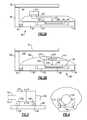
- FIG. 2Ashows a portion of an engine 80 .
- a fan case 82surrounds a fan rotor 84 .
- a bypass duct 86is defined inwardly of fan case 82 and outwardly of an intermediate case 89 .
- An inner core housing 88is spaced from intermediate housing 89 .
- a low pressure compressor 90 , a high pressure compressor 92 , a high pressure turbine 94 , and a low pressure turbine 96are shown schematically.
- Low pressure turbine 96drives the fan rotor 84 through a gear reduction 97 .
- a combustor 98is also shown.
- Cooling air to be utilizedis tapped at 100 , preferably at a location downstream of the high pressure compressor 92 such that it will be at high pressure.
- the airis passed into a heat exchanger 102 where it is cooled by bypass air in the bypass duct 86 . That cooled air is then returned to an inlet line 104 where it passes back into the engine and then may pass radially inwardly to cool components such as the high pressure turbine 94 .
- FIG. 2Bshows an engine 180 with an alternative mount location for the heat exchanger 204 .
- the elements described in FIG. 2Aare repeated with the reference numerals raised to 200s.
- the operationmay generally be similar to the FIG. 2A embodiment.
- a heat exchanger 204is mounted within an intermediate case 189 .
- a scoop inlet 200captures bypass air from the bypass duct 186 and brings it within the housing 189 , and over the heat exchanger 204 to an exit 202 . Air to be cooled is tapped from location 208 and returned to location 206 .
- FIG. 3show details of the mount of the heat exchanger 102 .
- the intermediate case 89has axially spaced flanges 106 .
- Damper mounts 108flexibly mount the heat exchanger 102 on the case 89 by being connected to the flanges 106 .
- the flexible mounts 108allow movement in two dimensions, generally, radially inwardly and outwardly as shown in FIG. 3 and also into and out of the plane of the paper of FIG. 3 , or circumferentially about the engine.
- FIG. 4is another view showing additional flexible damper mounts 112 connected to an additional structure 110 on the intermediate case 89 .
- Dampers 112also allow adjustment in two dimensions, axially along a center axis of the engine and also radially inwardly and outwardly.
- damperswhich may include at least four dampers, as shown, provides damping tolerance to resist vibration and also allows adjustment to withstand expansion and stresses.
- FIG. 5shows a flexible damper embodiment 120 .
- one portion 122has bolt holes 124 to be bolted to either the heat exchanger or the case as shown in FIGS. 3 and 4 .
- An outer area 123is shown adjacent the bolt holes 124 .
- a plurality of interdigitated fingers 126 / 128 and 134 / 136are shown. In the illustrated embodiment, there are four fingers 126 / 128 on portion 122 and four others 134 / 136 on an opposed portion 130 .
- the opposed portion 130is bolted through bolt holes 132 to the other of the heat exchanger and casing 89 .
- the fingersinclude outer fingers 126 and inner fingers 128 on portion 122 and outer fingers 134 and inner fingers 136 on portion 130 .
- the fingers 126 / 128are squeezed together by the outer area 123 at outer finger portions 125 compared to being separated by more space and in the area where they are interdigitated.
- the fingers 134 and 136are also squeezed together at outer portions 138 within the outer area 137 .
- a clamp member 140is squeezed at 142 to provide a spring for urging the fingers together.
- the fingersare allowed to move in two dimensions thus providing the damper function as mentioned above.
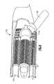
- Such a mountis particularly beneficial when highly engineered modern heat exchangers are used such as the heat exchanger 102 illustrated in FIG. 6 .
- FIG. 6shows a cross-section of an embodiment 102 schematically.
- heat exchanger 102there is line 100 leading to two lines 104 .
- Part of the flow pathincludes very small tubes 144 . With such fine tubes 144 , the provision of the vibration and stress damping is particularly beneficial.
- the heat exchanger such as shown in FIG. 6is disclosed in more detail in U.S. patent application Ser. No. 15/138,727, filed on Apr. 26, 2016 and entitled “Heat Exchanger with Heat Resistant Center Body.”
Landscapes
- Engineering & Computer Science (AREA)
- Chemical & Material Sciences (AREA)
- Combustion & Propulsion (AREA)
- Mechanical Engineering (AREA)
- General Engineering & Computer Science (AREA)
- Chemical Kinetics & Catalysis (AREA)
- General Chemical & Material Sciences (AREA)
- Structures Of Non-Positive Displacement Pumps (AREA)
Abstract
Description
Claims (17)
Priority Applications (2)
| Application Number | Priority Date | Filing Date | Title |
|---|---|---|---|
| US15/242,973US10436115B2 (en) | 2016-08-22 | 2016-08-22 | Heat exchanger for gas turbine engine with support damper mounting |
| EP17187328.4AEP3287621B1 (en) | 2016-08-22 | 2017-08-22 | Heat exchanger for gas turbine engine with support damper mounting |
Applications Claiming Priority (1)
| Application Number | Priority Date | Filing Date | Title |
|---|---|---|---|
| US15/242,973US10436115B2 (en) | 2016-08-22 | 2016-08-22 | Heat exchanger for gas turbine engine with support damper mounting |
Publications (2)
| Publication Number | Publication Date |
|---|---|
| US20180051630A1 US20180051630A1 (en) | 2018-02-22 |
| US10436115B2true US10436115B2 (en) | 2019-10-08 |
Family
ID=59738161
Family Applications (1)
| Application Number | Title | Priority Date | Filing Date |
|---|---|---|---|
| US15/242,973Active2037-08-16US10436115B2 (en) | 2016-08-22 | 2016-08-22 | Heat exchanger for gas turbine engine with support damper mounting |
Country Status (2)
| Country | Link |
|---|---|
| US (1) | US10436115B2 (en) |
| EP (1) | EP3287621B1 (en) |
Cited By (2)
| Publication number | Priority date | Publication date | Assignee | Title |
|---|---|---|---|---|
| US10907500B2 (en)* | 2015-02-06 | 2021-02-02 | Raytheon Technologies Corporation | Heat exchanger system with spatially varied additively manufactured heat transfer surfaces |
| US20220235705A1 (en)* | 2021-01-26 | 2022-07-28 | General Electric Company | Heat transfer system |
Families Citing this family (1)
| Publication number | Priority date | Publication date | Assignee | Title |
|---|---|---|---|---|
| US11111856B2 (en) | 2019-03-04 | 2021-09-07 | Pratt & Whitney Canada Corp | Turbofan engine and core link therefore |
Citations (41)
| Publication number | Priority date | Publication date | Assignee | Title |
|---|---|---|---|---|
| US3842597A (en)* | 1973-03-16 | 1974-10-22 | Gen Electric | Gas turbine engine with means for reducing the formation and emission of nitrogen oxides |
| US4180973A (en) | 1977-03-19 | 1980-01-01 | Kernforschungsanlage Julich Gesellschaft Mit Beschrankter Haftung | Vehicular gas turbine installation with ceramic recuperative heat exchanger elements arranged in rings around compressor, gas turbine and combustion chamber |
| US4254618A (en)* | 1977-08-18 | 1981-03-10 | General Electric Company | Cooling air cooler for a gas turbofan engine |
| US4474001A (en)* | 1981-04-01 | 1984-10-02 | United Technologies Corporation | Cooling system for the electrical generator of a turbofan gas turbine engine |
| US5297386A (en)* | 1992-08-26 | 1994-03-29 | Societe Nationale D'etude Et De Construction De Moteurs D'aviation (S.N.E.C.M.A.) | Cooling system for a gas turbine engine compressor |
| US5392614A (en)* | 1992-03-23 | 1995-02-28 | General Electric Company | Gas turbine engine cooling system |
| US5452573A (en)* | 1994-01-31 | 1995-09-26 | United Technologies Corporation | High pressure air source for aircraft and engine requirements |
| US5581996A (en)* | 1995-08-16 | 1996-12-10 | General Electric Company | Method and apparatus for turbine cooling |
| US5611197A (en)* | 1995-10-23 | 1997-03-18 | General Electric Company | Closed-circuit air cooled turbine |
| US5685158A (en)* | 1995-03-31 | 1997-11-11 | General Electric Company | Compressor rotor cooling system for a gas turbine |
| US5697208A (en)* | 1995-06-02 | 1997-12-16 | Solar Turbines Incorporated | Turbine cooling cycle |
| US5729969A (en)* | 1995-05-15 | 1998-03-24 | Aerospatiale Societe Nationale Industrielle | Device for bleeding off and cooling hot air in an aircraft engine |
| US5918458A (en)* | 1997-02-14 | 1999-07-06 | General Electric Company | System and method of providing clean filtered cooling air to a hot portion of a gas turbine engine |
| US20050022535A1 (en)* | 2003-07-28 | 2005-02-03 | Snecma Moteurs | Heat exchanger on a turbine cooling circuit |
| US20070130912A1 (en)* | 2005-12-08 | 2007-06-14 | General Electric Company | Shrouded turbofan bleed duct |
| US20080230651A1 (en)* | 2005-09-26 | 2008-09-25 | Airbus France | Turbofan Provided With a Pre-Cooler |
| US20080310955A1 (en)* | 2007-06-13 | 2008-12-18 | United Technologies Corporation | Hybrid cooling of a gas turbine engine |
| US20110162387A1 (en)* | 2008-10-03 | 2011-07-07 | Rolls-Royce Plc | Turbine cooling system |
| US20130108425A1 (en)* | 2011-10-28 | 2013-05-02 | James W. Norris | Rotating vane seal with cooling air passages |
| US8453456B2 (en) | 2009-03-25 | 2013-06-04 | United Technologies Corporation | Fuel-cooled flexible heat exchanger with thermoelectric device compression |
| US20130219854A1 (en)* | 2012-02-24 | 2013-08-29 | Daniel T. Alecu | Air-cooled oil cooler for turbofan engine |
| US8756910B2 (en)* | 2009-12-31 | 2014-06-24 | Rolls-Royce North American Technologies, Inc. | Gas turbine engine and cooling system |
| US8776869B2 (en) | 2005-01-07 | 2014-07-15 | Hiflux Limited | Heat exchanger with flexible tubular header connections |
| US20140208768A1 (en)* | 2012-01-06 | 2014-07-31 | Rolls-Royce Plc | Coolant supply system |
| US20140290272A1 (en)* | 2013-03-26 | 2014-10-02 | Thomas Gerard Mulcaire | Gas turbine engine cooling arrangement |
| US8858161B1 (en)* | 2007-11-29 | 2014-10-14 | Florida Turbine Technologies, Inc. | Multiple staged compressor with last stage airfoil cooling |
| US20160312704A1 (en)* | 2015-04-24 | 2016-10-27 | United Technologies Corporation | Intercooled cooling air with dual pass heat exchanger |
| US9677474B2 (en)* | 2013-11-18 | 2017-06-13 | Unison Industries, Llc | Surface cooler support mechanism |
| US20170268426A1 (en)* | 2016-03-18 | 2017-09-21 | United Technologies Corporation | Heat exchanger suspension system with pipe-to-linkage spring rate ratio |
| US20170298825A1 (en)* | 2016-04-13 | 2017-10-19 | United Technologies Corporation | Cooling Air Architecture for Compact Size and Performance Improvement |
| US20170306847A1 (en)* | 2016-04-26 | 2017-10-26 | United Technologies Corporation | Combined Drive for Cooling Air Using Cooing Compressor and Aircraft Air Supply Pump |
| US20170321605A1 (en)* | 2016-05-06 | 2017-11-09 | United Technologies Corporation | Heat temperature gradient heat exchanger |
| US20180010520A1 (en)* | 2015-01-30 | 2018-01-11 | Mitsubishi Hitachi Power Systems, Ltd. | Cooling system for gas turbine, gas turbine equipmentprovided with same, and parts cooling method for gas turbine |
| US20180038243A1 (en)* | 2016-08-05 | 2018-02-08 | General Electric Company | Oil cooling systems for a gas turbine engine |
| US20180058328A1 (en)* | 2016-08-23 | 2018-03-01 | United Technologies Corporation | Heat Exchanger for Gas Turbine Engine Mounted in Intermediate Case |
| US20180080383A1 (en)* | 2016-09-19 | 2018-03-22 | United Technologies Corporation | Gas turbine engine with intercooled cooling air and turbine drive |
| US20180080389A1 (en)* | 2016-09-21 | 2018-03-22 | United Technologies Corporation | Gas turbine engine with heat exchanger diagnostics |
| US20180142715A1 (en)* | 2015-06-01 | 2018-05-24 | A. Raymond Et Cie. Scs | Device For Retaining A Component |
| US20180156121A1 (en)* | 2016-12-05 | 2018-06-07 | United Technologies Corporation | Gas Turbine Engine With Intercooled Cooling Air and Controlled Boost Compressor |
| US20180187602A1 (en)* | 2015-02-12 | 2018-07-05 | United Technologies Corporation | Intercooled cooling air |
| US20180202358A1 (en)* | 2017-01-16 | 2018-07-19 | Pratt & Whitney Canada Corp. | Turbofan engine assembly with gearbox |
Family Cites Families (2)
| Publication number | Priority date | Publication date | Assignee | Title |
|---|---|---|---|---|
| US20110146944A1 (en)* | 2009-12-22 | 2011-06-23 | John Hand | Heat Exchanger Mounting Assembly |
| EP3567271B1 (en)* | 2016-01-14 | 2022-09-28 | Raytheon Technologies Corporation | Adjustable damper |
- 2016
- 2016-08-22USUS15/242,973patent/US10436115B2/enactiveActive
- 2017
- 2017-08-22EPEP17187328.4Apatent/EP3287621B1/enactiveActive
Patent Citations (41)
| Publication number | Priority date | Publication date | Assignee | Title |
|---|---|---|---|---|
| US3842597A (en)* | 1973-03-16 | 1974-10-22 | Gen Electric | Gas turbine engine with means for reducing the formation and emission of nitrogen oxides |
| US4180973A (en) | 1977-03-19 | 1980-01-01 | Kernforschungsanlage Julich Gesellschaft Mit Beschrankter Haftung | Vehicular gas turbine installation with ceramic recuperative heat exchanger elements arranged in rings around compressor, gas turbine and combustion chamber |
| US4254618A (en)* | 1977-08-18 | 1981-03-10 | General Electric Company | Cooling air cooler for a gas turbofan engine |
| US4474001A (en)* | 1981-04-01 | 1984-10-02 | United Technologies Corporation | Cooling system for the electrical generator of a turbofan gas turbine engine |
| US5392614A (en)* | 1992-03-23 | 1995-02-28 | General Electric Company | Gas turbine engine cooling system |
| US5297386A (en)* | 1992-08-26 | 1994-03-29 | Societe Nationale D'etude Et De Construction De Moteurs D'aviation (S.N.E.C.M.A.) | Cooling system for a gas turbine engine compressor |
| US5452573A (en)* | 1994-01-31 | 1995-09-26 | United Technologies Corporation | High pressure air source for aircraft and engine requirements |
| US5685158A (en)* | 1995-03-31 | 1997-11-11 | General Electric Company | Compressor rotor cooling system for a gas turbine |
| US5729969A (en)* | 1995-05-15 | 1998-03-24 | Aerospatiale Societe Nationale Industrielle | Device for bleeding off and cooling hot air in an aircraft engine |
| US5697208A (en)* | 1995-06-02 | 1997-12-16 | Solar Turbines Incorporated | Turbine cooling cycle |
| US5581996A (en)* | 1995-08-16 | 1996-12-10 | General Electric Company | Method and apparatus for turbine cooling |
| US5611197A (en)* | 1995-10-23 | 1997-03-18 | General Electric Company | Closed-circuit air cooled turbine |
| US5918458A (en)* | 1997-02-14 | 1999-07-06 | General Electric Company | System and method of providing clean filtered cooling air to a hot portion of a gas turbine engine |
| US20050022535A1 (en)* | 2003-07-28 | 2005-02-03 | Snecma Moteurs | Heat exchanger on a turbine cooling circuit |
| US8776869B2 (en) | 2005-01-07 | 2014-07-15 | Hiflux Limited | Heat exchanger with flexible tubular header connections |
| US20080230651A1 (en)* | 2005-09-26 | 2008-09-25 | Airbus France | Turbofan Provided With a Pre-Cooler |
| US20070130912A1 (en)* | 2005-12-08 | 2007-06-14 | General Electric Company | Shrouded turbofan bleed duct |
| US20080310955A1 (en)* | 2007-06-13 | 2008-12-18 | United Technologies Corporation | Hybrid cooling of a gas turbine engine |
| US8858161B1 (en)* | 2007-11-29 | 2014-10-14 | Florida Turbine Technologies, Inc. | Multiple staged compressor with last stage airfoil cooling |
| US20110162387A1 (en)* | 2008-10-03 | 2011-07-07 | Rolls-Royce Plc | Turbine cooling system |
| US8453456B2 (en) | 2009-03-25 | 2013-06-04 | United Technologies Corporation | Fuel-cooled flexible heat exchanger with thermoelectric device compression |
| US8756910B2 (en)* | 2009-12-31 | 2014-06-24 | Rolls-Royce North American Technologies, Inc. | Gas turbine engine and cooling system |
| US20130108425A1 (en)* | 2011-10-28 | 2013-05-02 | James W. Norris | Rotating vane seal with cooling air passages |
| US20140208768A1 (en)* | 2012-01-06 | 2014-07-31 | Rolls-Royce Plc | Coolant supply system |
| US20130219854A1 (en)* | 2012-02-24 | 2013-08-29 | Daniel T. Alecu | Air-cooled oil cooler for turbofan engine |
| US20140290272A1 (en)* | 2013-03-26 | 2014-10-02 | Thomas Gerard Mulcaire | Gas turbine engine cooling arrangement |
| US9677474B2 (en)* | 2013-11-18 | 2017-06-13 | Unison Industries, Llc | Surface cooler support mechanism |
| US20180010520A1 (en)* | 2015-01-30 | 2018-01-11 | Mitsubishi Hitachi Power Systems, Ltd. | Cooling system for gas turbine, gas turbine equipmentprovided with same, and parts cooling method for gas turbine |
| US20180187602A1 (en)* | 2015-02-12 | 2018-07-05 | United Technologies Corporation | Intercooled cooling air |
| US20160312704A1 (en)* | 2015-04-24 | 2016-10-27 | United Technologies Corporation | Intercooled cooling air with dual pass heat exchanger |
| US20180142715A1 (en)* | 2015-06-01 | 2018-05-24 | A. Raymond Et Cie. Scs | Device For Retaining A Component |
| US20170268426A1 (en)* | 2016-03-18 | 2017-09-21 | United Technologies Corporation | Heat exchanger suspension system with pipe-to-linkage spring rate ratio |
| US20170298825A1 (en)* | 2016-04-13 | 2017-10-19 | United Technologies Corporation | Cooling Air Architecture for Compact Size and Performance Improvement |
| US20170306847A1 (en)* | 2016-04-26 | 2017-10-26 | United Technologies Corporation | Combined Drive for Cooling Air Using Cooing Compressor and Aircraft Air Supply Pump |
| US20170321605A1 (en)* | 2016-05-06 | 2017-11-09 | United Technologies Corporation | Heat temperature gradient heat exchanger |
| US20180038243A1 (en)* | 2016-08-05 | 2018-02-08 | General Electric Company | Oil cooling systems for a gas turbine engine |
| US20180058328A1 (en)* | 2016-08-23 | 2018-03-01 | United Technologies Corporation | Heat Exchanger for Gas Turbine Engine Mounted in Intermediate Case |
| US20180080383A1 (en)* | 2016-09-19 | 2018-03-22 | United Technologies Corporation | Gas turbine engine with intercooled cooling air and turbine drive |
| US20180080389A1 (en)* | 2016-09-21 | 2018-03-22 | United Technologies Corporation | Gas turbine engine with heat exchanger diagnostics |
| US20180156121A1 (en)* | 2016-12-05 | 2018-06-07 | United Technologies Corporation | Gas Turbine Engine With Intercooled Cooling Air and Controlled Boost Compressor |
| US20180202358A1 (en)* | 2017-01-16 | 2018-07-19 | Pratt & Whitney Canada Corp. | Turbofan engine assembly with gearbox |
Non-Patent Citations (1)
| Title |
|---|
| European Search Report for European Application No. 17187328.4 dated Jan. 17, 2018. |
Cited By (3)
| Publication number | Priority date | Publication date | Assignee | Title |
|---|---|---|---|---|
| US10907500B2 (en)* | 2015-02-06 | 2021-02-02 | Raytheon Technologies Corporation | Heat exchanger system with spatially varied additively manufactured heat transfer surfaces |
| US20220235705A1 (en)* | 2021-01-26 | 2022-07-28 | General Electric Company | Heat transfer system |
| US11512639B2 (en)* | 2021-01-26 | 2022-11-29 | General Electric Company | Heat transfer system |
Also Published As
| Publication number | Publication date |
|---|---|
| US20180051630A1 (en) | 2018-02-22 |
| EP3287621B1 (en) | 2023-05-10 |
| EP3287621A1 (en) | 2018-02-28 |
Similar Documents
| Publication | Publication Date | Title |
|---|---|---|
| EP3090163A2 (en) | Compressor rim thermal management | |
| US10526916B2 (en) | Heat exchanger with heat resistant center body | |
| EP3330524A1 (en) | Heat exchanger mounted at rear of gas turbine engine for challenging temperature applications | |
| US9970323B2 (en) | Geared turbofan engine with optimized diffuser case flange location | |
| EP3330515B1 (en) | Gas turbine engine | |
| EP3287621B1 (en) | Heat exchanger for gas turbine engine with support damper mounting | |
| US10662792B2 (en) | Gas turbine engine cooling fluid composite tube | |
| US10982595B2 (en) | Heat exchanger for gas turbine engine mounted in intermediate case | |
| US20180045218A1 (en) | Shim for gas turbine engine | |
| US10774685B2 (en) | Gas turbine engine exhaust component | |
| US20220056847A1 (en) | External mixing chamber for a gas turbine engine with cooled turbine cooling air | |
| US10711640B2 (en) | Cooled cooling air to blade outer air seal passing through a static vane | |
| EP3181869B1 (en) | Compressor core inner diameter cooling | |
| US10184354B2 (en) | Windback heat shield | |
| US11649770B1 (en) | Bleed hole flow discourager | |
| US10823071B2 (en) | Multi-source turbine cooling air |
Legal Events
| Date | Code | Title | Description |
|---|---|---|---|
| AS | Assignment | Owner name:UNITED TECHNOLOGIES CORPORATION, CONNECTICUT Free format text:ASSIGNMENT OF ASSIGNORS INTEREST;ASSIGNORS:DUESLER, PAUL W.;SCHWARZ, FREDERICK M.;SIGNING DATES FROM 20160822 TO 20160823;REEL/FRAME:039503/0240 | |
| STPP | Information on status: patent application and granting procedure in general | Free format text:EX PARTE QUAYLE ACTION MAILED | |
| STPP | Information on status: patent application and granting procedure in general | Free format text:RESPONSE TO EX PARTE QUAYLE ACTION ENTERED AND FORWARDED TO EXAMINER | |
| STPP | Information on status: patent application and granting procedure in general | Free format text:NOTICE OF ALLOWANCE MAILED -- APPLICATION RECEIVED IN OFFICE OF PUBLICATIONS | |
| STPP | Information on status: patent application and granting procedure in general | Free format text:PUBLICATIONS -- ISSUE FEE PAYMENT VERIFIED | |
| STCF | Information on status: patent grant | Free format text:PATENTED CASE | |
| AS | Assignment | Owner name:RAYTHEON TECHNOLOGIES CORPORATION, MASSACHUSETTS Free format text:CHANGE OF NAME;ASSIGNOR:UNITED TECHNOLOGIES CORPORATION;REEL/FRAME:054062/0001 Effective date:20200403 | |
| AS | Assignment | Owner name:RAYTHEON TECHNOLOGIES CORPORATION, CONNECTICUT Free format text:CORRECTIVE ASSIGNMENT TO CORRECT THE AND REMOVE PATENT APPLICATION NUMBER 11886281 AND ADD PATENT APPLICATION NUMBER 14846874. TO CORRECT THE RECEIVING PARTY ADDRESS PREVIOUSLY RECORDED AT REEL: 054062 FRAME: 0001. ASSIGNOR(S) HEREBY CONFIRMS THE CHANGE OF ADDRESS;ASSIGNOR:UNITED TECHNOLOGIES CORPORATION;REEL/FRAME:055659/0001 Effective date:20200403 | |
| MAFP | Maintenance fee payment | Free format text:PAYMENT OF MAINTENANCE FEE, 4TH YEAR, LARGE ENTITY (ORIGINAL EVENT CODE: M1551); ENTITY STATUS OF PATENT OWNER: LARGE ENTITY Year of fee payment:4 | |
| AS | Assignment | Owner name:RTX CORPORATION, CONNECTICUT Free format text:CHANGE OF NAME;ASSIGNOR:RAYTHEON TECHNOLOGIES CORPORATION;REEL/FRAME:064714/0001 Effective date:20230714 |