US10434488B2 - Systems and methods for facilitating dissociation of methane utilizing a reactor designed to generate shockwaves in a supersonic gaseous vortex - Google Patents
Systems and methods for facilitating dissociation of methane utilizing a reactor designed to generate shockwaves in a supersonic gaseous vortexDownload PDFInfo
- Publication number
- US10434488B2 US10434488B2US14/823,890US201514823890AUS10434488B2US 10434488 B2US10434488 B2US 10434488B2US 201514823890 AUS201514823890 AUS 201514823890AUS 10434488 B2US10434488 B2US 10434488B2
- Authority
- US
- United States
- Prior art keywords
- chamber
- methane
- reactor
- gas
- carbon
- Prior art date
- Legal status (The legal status is an assumption and is not a legal conclusion. Google has not performed a legal analysis and makes no representation as to the accuracy of the status listed.)
- Expired - Fee Related
Links
- VNWKTOKETHGBQD-UHFFFAOYSA-NmethaneChemical compoundCVNWKTOKETHGBQD-UHFFFAOYSA-N0.000titleclaimsabstract64
- 238000010494dissociation reactionMethods0.000titleclaimsabstract12
- 230000005593dissociationsEffects0.000titleclaimsabstract12
- 238000000034methodMethods0.000titleclaims8
- 239000000047productSubstances0.000claimsabstract16
- OKTJSMMVPCPJKN-UHFFFAOYSA-NCarbonChemical compound[C]OKTJSMMVPCPJKN-UHFFFAOYSA-N0.000claimsabstract13
- 229910052799carbonInorganic materials0.000claimsabstract13
- 238000007781pre-processingMethods0.000claimsabstract10
- 239000006227byproductSubstances0.000claimsabstract9
- 239000007787solidSubstances0.000claimsabstract4
- 239000007789gasSubstances0.000claims36
- 230000007423decreaseEffects0.000claims3
- KDLHZDBZIXYQEI-UHFFFAOYSA-NPalladiumChemical compound[Pd]KDLHZDBZIXYQEI-UHFFFAOYSA-N0.000claims2
- 150000001336alkenesChemical class0.000claims2
- 229910003481amorphous carbonInorganic materials0.000claims2
- 239000011852carbon nanoparticleChemical group0.000claims2
- 230000003197catalytic effectEffects0.000claims2
- 239000000428dustSubstances0.000claims2
- 229910052739hydrogenInorganic materials0.000claims2
- 239000001257hydrogenSubstances0.000claims2
- 125000004435hydrogen atomChemical class[H]*0.000claims2
- 239000000463materialSubstances0.000claims2
- 239000000203mixtureSubstances0.000claims2
- BASFCYQUMIYNBI-UHFFFAOYSA-NplatinumChemical compound[Pt]BASFCYQUMIYNBI-UHFFFAOYSA-N0.000claims2
- NRTOMJZYCJJWKI-UHFFFAOYSA-NTitanium nitrideChemical compound[Ti]#NNRTOMJZYCJJWKI-UHFFFAOYSA-N0.000claims1
- 238000006243chemical reactionMethods0.000claims1
- 229910003460diamondInorganic materials0.000claims1
- 239000010432diamondSubstances0.000claims1
- 238000010438heat treatmentMethods0.000claims1
- 229910052763palladiumInorganic materials0.000claims1
- 229910052697platinumInorganic materials0.000claims1
- 239000007921spraySubstances0.000claims1
- MTPVUVINMAGMJL-UHFFFAOYSA-Ntrimethyl(1,1,2,2,2-pentafluoroethyl)silaneChemical compoundC[Si](C)(C)C(F)(F)C(F)(F)FMTPVUVINMAGMJL-UHFFFAOYSA-N0.000claims1
- UONOETXJSWQNOL-UHFFFAOYSA-Ntungsten carbideChemical compound[W+]#[C-]UONOETXJSWQNOL-UHFFFAOYSA-N0.000claims1
Images


Classifications
- B—PERFORMING OPERATIONS; TRANSPORTING
- B01—PHYSICAL OR CHEMICAL PROCESSES OR APPARATUS IN GENERAL
- B01J—CHEMICAL OR PHYSICAL PROCESSES, e.g. CATALYSIS OR COLLOID CHEMISTRY; THEIR RELEVANT APPARATUS
- B01J19/00—Chemical, physical or physico-chemical processes in general; Their relevant apparatus
- B01J19/08—Processes employing the direct application of electric or wave energy, or particle radiation; Apparatus therefor
- B01J19/10—Processes employing the direct application of electric or wave energy, or particle radiation; Apparatus therefor employing sonic or ultrasonic vibrations
- B—PERFORMING OPERATIONS; TRANSPORTING
- B01—PHYSICAL OR CHEMICAL PROCESSES OR APPARATUS IN GENERAL
- B01J—CHEMICAL OR PHYSICAL PROCESSES, e.g. CATALYSIS OR COLLOID CHEMISTRY; THEIR RELEVANT APPARATUS
- B01J15/00—Chemical processes in general for reacting gaseous media with non-particulate solids, e.g. sheet material; Apparatus specially adapted therefor
- B01J15/005—Chemical processes in general for reacting gaseous media with non-particulate solids, e.g. sheet material; Apparatus specially adapted therefor in the presence of catalytically active bodies, e.g. porous plates
- B—PERFORMING OPERATIONS; TRANSPORTING
- B01—PHYSICAL OR CHEMICAL PROCESSES OR APPARATUS IN GENERAL
- B01J—CHEMICAL OR PHYSICAL PROCESSES, e.g. CATALYSIS OR COLLOID CHEMISTRY; THEIR RELEVANT APPARATUS
- B01J19/00—Chemical, physical or physico-chemical processes in general; Their relevant apparatus
- B01J19/0053—Details of the reactor
- B—PERFORMING OPERATIONS; TRANSPORTING
- B01—PHYSICAL OR CHEMICAL PROCESSES OR APPARATUS IN GENERAL
- B01J—CHEMICAL OR PHYSICAL PROCESSES, e.g. CATALYSIS OR COLLOID CHEMISTRY; THEIR RELEVANT APPARATUS
- B01J19/00—Chemical, physical or physico-chemical processes in general; Their relevant apparatus
- B01J19/02—Apparatus characterised by being constructed of material selected for its chemically-resistant properties
- B—PERFORMING OPERATIONS; TRANSPORTING
- B01—PHYSICAL OR CHEMICAL PROCESSES OR APPARATUS IN GENERAL
- B01J—CHEMICAL OR PHYSICAL PROCESSES, e.g. CATALYSIS OR COLLOID CHEMISTRY; THEIR RELEVANT APPARATUS
- B01J19/00—Chemical, physical or physico-chemical processes in general; Their relevant apparatus
- B01J19/24—Stationary reactors without moving elements inside
- B01J19/2405—Stationary reactors without moving elements inside provoking a turbulent flow of the reactants, such as in cyclones, or having a high Reynolds-number
- B—PERFORMING OPERATIONS; TRANSPORTING
- B01—PHYSICAL OR CHEMICAL PROCESSES OR APPARATUS IN GENERAL
- B01J—CHEMICAL OR PHYSICAL PROCESSES, e.g. CATALYSIS OR COLLOID CHEMISTRY; THEIR RELEVANT APPARATUS
- B01J4/00—Feed or outlet devices; Feed or outlet control devices
- B01J4/001—Feed or outlet devices as such, e.g. feeding tubes
- B01J4/002—Nozzle-type elements
- C—CHEMISTRY; METALLURGY
- C01—INORGANIC CHEMISTRY
- C01B—NON-METALLIC ELEMENTS; COMPOUNDS THEREOF; METALLOIDS OR COMPOUNDS THEREOF NOT COVERED BY SUBCLASS C01C
- C01B3/00—Hydrogen; Gaseous mixtures containing hydrogen; Separation of hydrogen from mixtures containing it; Purification of hydrogen
- C01B3/02—Production of hydrogen or of gaseous mixtures containing a substantial proportion of hydrogen
- C01B3/22—Production of hydrogen or of gaseous mixtures containing a substantial proportion of hydrogen by decomposition of gaseous or liquid organic compounds
- C01B3/24—Production of hydrogen or of gaseous mixtures containing a substantial proportion of hydrogen by decomposition of gaseous or liquid organic compounds of hydrocarbons
- B—PERFORMING OPERATIONS; TRANSPORTING
- B01—PHYSICAL OR CHEMICAL PROCESSES OR APPARATUS IN GENERAL
- B01J—CHEMICAL OR PHYSICAL PROCESSES, e.g. CATALYSIS OR COLLOID CHEMISTRY; THEIR RELEVANT APPARATUS
- B01J2219/00—Chemical, physical or physico-chemical processes in general; Their relevant apparatus
- B01J2219/00049—Controlling or regulating processes
- B01J2219/00051—Controlling the temperature
- B01J2219/00074—Controlling the temperature by indirect heating or cooling employing heat exchange fluids
- B01J2219/00087—Controlling the temperature by indirect heating or cooling employing heat exchange fluids with heat exchange elements outside the reactor
- B—PERFORMING OPERATIONS; TRANSPORTING
- B01—PHYSICAL OR CHEMICAL PROCESSES OR APPARATUS IN GENERAL
- B01J—CHEMICAL OR PHYSICAL PROCESSES, e.g. CATALYSIS OR COLLOID CHEMISTRY; THEIR RELEVANT APPARATUS
- B01J2219/00—Chemical, physical or physico-chemical processes in general; Their relevant apparatus
- B01J2219/02—Apparatus characterised by their chemically-resistant properties
- B01J2219/0204—Apparatus characterised by their chemically-resistant properties comprising coatings on the surfaces in direct contact with the reactive components
- B—PERFORMING OPERATIONS; TRANSPORTING
- B01—PHYSICAL OR CHEMICAL PROCESSES OR APPARATUS IN GENERAL
- B01J—CHEMICAL OR PHYSICAL PROCESSES, e.g. CATALYSIS OR COLLOID CHEMISTRY; THEIR RELEVANT APPARATUS
- B01J2219/00—Chemical, physical or physico-chemical processes in general; Their relevant apparatus
- B01J2219/08—Processes employing the direct application of electric or wave energy, or particle radiation; Apparatus therefor
- B01J2219/0869—Feeding or evacuating the reactor
- B—PERFORMING OPERATIONS; TRANSPORTING
- B01—PHYSICAL OR CHEMICAL PROCESSES OR APPARATUS IN GENERAL
- B01J—CHEMICAL OR PHYSICAL PROCESSES, e.g. CATALYSIS OR COLLOID CHEMISTRY; THEIR RELEVANT APPARATUS
- B01J2219/00—Chemical, physical or physico-chemical processes in general; Their relevant apparatus
- B01J2219/08—Processes employing the direct application of electric or wave energy, or particle radiation; Apparatus therefor
- B01J2219/0873—Materials to be treated
- B01J2219/0875—Gas
- B—PERFORMING OPERATIONS; TRANSPORTING
- B01—PHYSICAL OR CHEMICAL PROCESSES OR APPARATUS IN GENERAL
- B01J—CHEMICAL OR PHYSICAL PROCESSES, e.g. CATALYSIS OR COLLOID CHEMISTRY; THEIR RELEVANT APPARATUS
- B01J2219/00—Chemical, physical or physico-chemical processes in general; Their relevant apparatus
- B01J2219/08—Processes employing the direct application of electric or wave energy, or particle radiation; Apparatus therefor
- B01J2219/0873—Materials to be treated
- B01J2219/0892—Materials to be treated involving catalytically active material
- B—PERFORMING OPERATIONS; TRANSPORTING
- B01—PHYSICAL OR CHEMICAL PROCESSES OR APPARATUS IN GENERAL
- B01J—CHEMICAL OR PHYSICAL PROCESSES, e.g. CATALYSIS OR COLLOID CHEMISTRY; THEIR RELEVANT APPARATUS
- B01J2219/00—Chemical, physical or physico-chemical processes in general; Their relevant apparatus
- B01J2219/19—Details relating to the geometry of the reactor
- B01J2219/194—Details relating to the geometry of the reactor round
- B01J2219/1941—Details relating to the geometry of the reactor round circular or disk-shaped
- B01J2219/1946—Details relating to the geometry of the reactor round circular or disk-shaped conical
- C—CHEMISTRY; METALLURGY
- C01—INORGANIC CHEMISTRY
- C01B—NON-METALLIC ELEMENTS; COMPOUNDS THEREOF; METALLOIDS OR COMPOUNDS THEREOF NOT COVERED BY SUBCLASS C01C
- C01B2203/00—Integrated processes for the production of hydrogen or synthesis gas
- C01B2203/02—Processes for making hydrogen or synthesis gas
- C01B2203/0266—Processes for making hydrogen or synthesis gas containing a decomposition step
- C01B2203/0272—Processes for making hydrogen or synthesis gas containing a decomposition step containing a non-catalytic decomposition step
- C—CHEMISTRY; METALLURGY
- C01—INORGANIC CHEMISTRY
- C01B—NON-METALLIC ELEMENTS; COMPOUNDS THEREOF; METALLOIDS OR COMPOUNDS THEREOF NOT COVERED BY SUBCLASS C01C
- C01B2203/00—Integrated processes for the production of hydrogen or synthesis gas
- C01B2203/04—Integrated processes for the production of hydrogen or synthesis gas containing a purification step for the hydrogen or the synthesis gas
- C—CHEMISTRY; METALLURGY
- C01—INORGANIC CHEMISTRY
- C01B—NON-METALLIC ELEMENTS; COMPOUNDS THEREOF; METALLOIDS OR COMPOUNDS THEREOF NOT COVERED BY SUBCLASS C01C
- C01B2203/00—Integrated processes for the production of hydrogen or synthesis gas
- C01B2203/12—Feeding the process for making hydrogen or synthesis gas
- C01B2203/1205—Composition of the feed
- C01B2203/1211—Organic compounds or organic mixtures used in the process for making hydrogen or synthesis gas
- C01B2203/1235—Hydrocarbons
- C01B2203/1241—Natural gas or methane
Definitions
- This disclosurerelates to systems and methods for facilitating dissociation of methane at low temperatures and/or pressures utilizing a reactor designed to generate shockwaves in a supersonic gaseous vortex.
- One aspect of the disclosurerelates to a system configured for facilitating dissociation of methane at low temperatures and/or pressures utilizing a reactor designed to generate shockwaves in a supersonic gaseous vortex.
- the systemby using a combination of mechano chemistry and catalysis, may achieve disassociation of methane at relatively low temperatures and/or relatively low pressures.
- the systemmay be scaled across a very wide range from implementations configured to process kilos of methane per hour to implementations configured to process thousands of kilos of methane per hour.
- the reactormay be constructed from non-exotic materials.
- the systemmay include one or more of a preprocessing chamber, a reactor, a gas/solid separator, and/or other components.
- the preprocessing chambermay be configured to receive methane.
- the preprocessing chambermay be configured to pressurize the methane to a pressure of 300 kPa or more.
- the preprocessing chambermay be configured to heat the methane to a temperature below a dissociation temperature of methane.
- the reactormay be configured to dissociate methane received from the preprocessing chamber.
- the reactormay be configured to operate at a temperature above the dissociation temperature of methane.
- the reactormay include a chamber having an internal surface that is substantially axially symmetrical about a longitudinal axis.
- the reactormay include a gas inlet disposed at a first end of the chamber and arranged to emit the methane as a gas stream substantially tangentially to the inner surface of the chamber to effectuate a gaseous vortex rotating about the longitudinal axis within the chamber.
- the gas inletmay comprise a nozzle that accelerates the gas stream to a supersonic velocity.
- the nozzlemay be structured to adjustably control a frequency of shockwaves emitted from the nozzle into the gaseous vortex.
- the reactormay include an outlet disposed on the longitudinal axis at a second end of the chamber opposite from the first end. The outlet may be configured to emit product gases and carbon byproduct from the chamber.
- the gas/solid separatormay be configured to receive the product gases and carbon byproduct from the reactor and separate out the carbon byproduct from the product gases.
- the methodmay include receiving methane into a preprocessing chamber.
- the methodmay include pressurizing the methane within the preprocessing chamber to a pressure of 350 kPa or more.
- the methodmay include heating the methane within the preprocessing chamber to a temperature below a dissociation temperature of methane.
- the methodmay include introducing the pressurized and heated methane from the preprocessing chamber into a reactor configured to dissociate methane.
- the reactormay be configured to operate at a temperature above the dissociation temperature of methane.
- the methanemay be introduced into the reactor as a gas stream substantially tangentially to an inner surface of a chamber of the reactor to effectuate a gaseous vortex rotating about the longitudinal axis within the chamber.
- the gas streammay be introduced via a gas inlet.
- the gas inletmay comprise a nozzle that accelerates the gas stream to a supersonic velocity.
- the methodmay include controlling a frequency of shockwaves emitted from the nozzle into the gaseous vortex.
- the methodmay include emitting product gas and carbon byproduct from the chamber of the reactor via an outlet disposed on the longitudinal axis at a second end of the chamber opposite from the first end.
- the methodmay include separating out the carbon byproduct from the product gas using a gas/solid separator.
- Exemplary implementationsmay provide a very economical way of producing large quantities of carbon and hydrogen. Gas that would otherwise be flared may instead be turned into useful end products. Carbon may be traded or used to improve soil fertility. Hydrogen may be used for clean energy production with the exhaust being water. It should be noted, however, that for some implementations only some (or none) of the identified advantages may be present and the potential advantages are not necessarily required for all of the implementations.
- FIG. 1Aillustrates a system configured for facilitating dissociation of methane at low temperatures and/or pressures utilizing a reactor designed to generate shockwaves in a supersonic gaseous vortex, in accordance with one or more implementations.
- FIG. 1illustrates a top view of a reactor, in accordance with one or more implementations.
- FIG. 2illustrates a side view of the reactor, in accordance with one or more implementations.
- FIG. 3illustrates one example of first replaceable wear part of the reactor shown in FIGS. 1 and 2 in a detailed view.
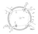
- FIG. 4illustrates one example of including multiple gas inlets and replaceable wear parts in the reactor shown in FIGS. 1 and 2 .
- FIG. 5illustrates one example of a shape of the interior volume of chamber designed to control the wear impact.
- FIG. 6illustrates a method for facilitating dissociation of methane at low temperatures and/or pressures utilizing a reactor designed to generate shockwaves in a supersonic gaseous vortex, in accordance with one or more implementations.
- FIG. 1Aillustrates a system 170 configured for facilitating dissociation of methane at low temperatures and/or pressures utilizing a reactor 100 designed to generate shockwaves in a supersonic gaseous vortex, in accordance with one or more implementations.
- system 170may include one or more of a preprocessing chamber 172 , a gas/solid separator 176 , a product gas separator 178 , and/or other components.
- the preprocessing chamber 172may be configured to receive methane.
- the preprocessing chamber 172may be configured to pressurize the methane.
- the methanemay be pressurized to a pressure of 350 kPa or more.
- the preprocessing chamber 172may be configured to heat the methane.
- the methanemay be heated to a temperature below a dissociation temperature of methane. The pressurization and/or heating of the methane may be achieved with conventional apparatuses suited for those purposes, in accordance with some implementations.
- the reactor 100may be configured to receive methane from the preprocessing chamber 172 .
- the reactormay be configured to dissociate methane.
- the reactormay be configured to operate at a temperature above the dissociation temperature of methane.
- the methanemay enter the reactor 100 through a converging diverging nozzle.
- the nozzle dimensionsmay be configured to cause the methane exiting the nozzle to be travelling at least one and a half times speed of sound in methane at that temperature and pressure.
- the nozzlemay be designed to impart supersonic shock waves in the gas.
- the methanemay be dissociated into one or more produce gases and/or one or more carbon byproducts. Examples of product gases and carbon byproducts may include one or more of hydrogen, alkenes, carbon dust, amorphous carbon, graphitic carbon, carbon nanoparticle structures, carbon nano tubes, graphene and/or other product gases and/or carbon by products.
- FIGS. 1 and 2illustrate a top and a side view of reactor 100 , respectively, in accordance with one or more implementations. With continuous reference to FIGS. 1 and 2 , reactor 100 will be described. As shown, reactor 100 may include one or more of a chamber 102 , a first gas inlet 104 , an outlet 108 , a second gas inlet 110 , a first replaceable wear part 112 , and/or other components.
- Chamber 102may be configured to provide a volume in which methane processing occurs.
- Chamber 102may have a substantially circular cross-section centered on a longitudinal axis 124 that is normal to the cross-section.
- the substantially circular cross-sectionmay facilitate a vortex rotating within chamber 102 .
- a radius of the substantially circular cross-section of chamber 102may continuously decrease at an end of chamber 102 proximal to outlet 108 .
- the continuous decrease of the radius of the substantially circular cross-section of chamber 102may be configured to cause an acceleration of a rotational speed of the gaseous vortex.
- As the continuous decrease of the radius of the substantially circular cross-section of chamber 102may be shaped as a cone (illustrated in FIG. 2 ), a hemisphere, a horn-shape, and/or other shapes.
- Chamber 102may be formed of various materials. Chamber 102 may be formed of a rigid material. Chamber 102 may be formed of a thermally conductive material. Chamber 102 may be formed of an electrically conductive material. According to some implementations, chamber 102 may be formed wholly or partially of steel, iron, iron alloys, silicon carbide, partially stabilized zirconia (PSZ), fused alumina, tungsten carbide, boron nitride, carbides, nitrides, ceramics, silicates, geopolymers, metallic alloys, other alloys, and/or other materials. In some implementations, an internal surface 116 of chamber 102 may be coated with one or more coatings.
- PSZpartially stabilized zirconia
- An exemplary coatingmay be configured to prevent physical or chemical wear to internal surface 116 of chamber 102 .
- a coatingmay be configured to promote a chemical reaction within chamber 102 .
- An example of a coating that may promote a chemical reactionmay include one or more of iron; nickel; ruthenium; rhodium; platinum; palladium; cobalt; other transition metals and their alloys, compounds, and/or oxides (e.g., the lanthanide series and their compounds, alloys, and/or oxides); and/or other materials.
- the first gas inlet 104may be configured to introduce a high-velocity stream of methane gas into chamber 102 .
- the first gas inlet 104may be disposed and arranged so as to effectuate a vortex of the stream of gas circulating within chamber 102 .
- the vortexmay rotate about longitudinal axis of chamber 102 .
- the gas inletmay be disposed so that the gas stream 116 is directed substantially perpendicular to longitudinal axis 124 of chamber 102 .
- the first gas inlet 104may be disposed so that the gas stream 116 is directed substantially tangent to a portion of the internal surface 126 of the substantially circular cross-section of chamber 102 .
- the first gas inlet 104may comprise inlet gas nozzle (not depicted in this example) disposed within the first gas inlet 104 .
- the inlet nozzlemay be configured to accelerate the stream of gas being introduced into chamber 102 , to emit the stream of gas at a supersonic speed, to emit shockwaves in the stream of gas emitted from inlet nozzle, and/or for any other purposes.
- Exemplary implementations of a gas inlet (e.g., first gas inlet 104 ) and/or an inlet nozzleare disclosed in U.S. patent application Ser. No. 14/298,868 filed on Jun.
- the gas stream 116 introduced by the first gas inlet 104may include any number of gaseous materials.
- the gasmay include one or more of steam, methane, ethane, propane, butane, pentane, ammonia, hydrogen, carbon monoxide, carbon dioxide, oxygen, nitrogen, chlorine, fluorine, ethene, hydrogen sulphide, acetylene, carbonyls and/or other halogenated metal complexes, and/or other gaseous materials.
- in the gasa wide variety of chemical reactions that are normally multiple step reactions, e.g., due to Le Chateliers principle.
- Such a wide variety of chemical reactionsmay be possible in the reactor 100 because of the wide temperature and pressure difference within the reactor 100 itself. As soon as a given reaction has taken place due to pressure and/or temperature and/or catalytic action within the reactor the products are conveyed to a region within the reactor in nanoseconds where the temperature and pressure are reduced. This makes a great number of organic and organo metal reactions possible in a greatly reduced number of steps. It also makes many chemical reactions possible or economic that are not presently practicable or even attainable. Applications include pharmaceuticals, insecticides, and the precursor organo metals or carbonyls, which are used in Chemical Vapor Deposition (CVD) used in integrated circuit manufacture, electronics in general as well as 3D printing of metals
- CVDChemical Vapor Deposition
- Methanemay be processed by reactor 100 by mechanisms facilitated by shockwaves 128 within chamber 102 .
- methanemay be processed by cavitation in the stream of gas within chamber 102 .
- Methanemay undergo a chemical transformation due to the catalytic effect built into the first replaceable part wear part 112 , and/or due to the electric field imparted on the first replaceable part wear part 122 .
- the outlet 108may be configured to emit the gas and processed material from chamber 102 .
- the outlet 108may be disposed at an end of chamber 102 opposite to the first gas inlet 104 .
- the outletmay be disposed on longitudinal axis 124 of chamber 102 .
- outlet 108may include one or more of an outlet nozzle 130 (illustrated in FIG. 2 ) disposed within outlet 108 .
- the outlet nozzle 130may be configured to pressurize chamber 102 .
- the outlet nozzle 130may be configured to effectuate a rapid cooling of processed gases and/or carbon byproducts exiting chamber 102 . According to some implementations, such rapid cooling may reduce or minimize back reactions.
- the outlet nozzle 130may include a venturi tube (not depicted).
- a first replaceable wear part 112may be disposed at a first portion 122 of the inner surface 126 of chamber 102 .
- the first portion 122may be an area on the inner surface 126 where the stream 116 contacts the surface 126 . As such, the first portion 122 may be opposite to the first gas inlet 104 within chamber 102 .
- the first replaceable wear part 112may be disposed at the first portion 122 in a way to absorb impacts to first portion 122 on the inner surface 126 caused by gases and/or carbon byproducts entrained by the gas stream 116 introduced by the first gas inlet 104 .
- the first replaceable wear part 112may be made of hard material such as tungsten carbide, titanium carbide, or titanium nitride, diamond, and/or any other materials for wear resistance. In some implementations, the first replaceable wear part 112 may have a polycrystalline diamond facing.
- the first replaceable wear part 122may be configured to continuously advance into the chamber as the surface of the contact end is worn.
- FIG. 3illustrates one example of a first replaceable wear part 122 in a detailed view. It will be described with reference to FIGS. 1 and 2 .
- the first replaceable wear part 112may comprise a first end 112 A, e.g., the contacting end of the first replaceable wear part 112 , and a second end 122 B that is opposite to the first end 112 A.
- the first replaceable wear part 112may comprise a thruster 136 configured to continuously feed the first replaceable wear part 112 into chamber 102 as the surface of the first replaceable wear part 112 is worn by the impacts caused by the carbon byproducts.
- casing 138may be employed to be lined around chamber 102 and serve as a support to the first replaceable wear part 112 .
- seals 140may be employed around the casing 138 where the first replaceable wear part 112 enters chamber 102 . Seals 140 may facilitate removal of the first replaceable wear part 112 for maintenance or replacement. The facilitated removal of first replaceable wear part 112 may reduce scheduled downtime as compared to the conventional jet mill.
- a second replaceable wear part 150may be coupled to the first replaceable wear part 112 at the second end 112 B of the first replaceable wear part 112 . This may facilitate continuous feeding of replaceable wear parts into chamber 102 .
- the first replaceable wear part 112may comprise a rotatable cylindrical rod adapted to control impacts of carbon byproducts.
- the cylindrical rodmay rotate about the axis of its cylinder when the pulverized particles contact the rod. The rotation of the rod may allow the wear to be controlled on the surface of the rod.
- the contacting end of the first replaceable wear part 112may be coated with catalyst material.
- the coatingmay be configured to protect the surface of the contacting end of the first replaceable wear part 112 , and/or to promote a chemical reaction within chamber 102 .
- the catalyst materialmay be incorporated into the matrix of the first replaceable wear part 112 during manufacturing of the first replaceable wear part 112 .
- the catalyst material that may be coated on the contacting end of the first replaceable wear part 112may include one or more of platinum, palladium, and/or any other catalyst material for aiding the chemical reaction(s), and/or the comminution inside chamber 102 .
- the coating on the first replaceable wear part 112may be configured such that the coated catalyst material ablates from the surface of the first replaceable wear part 112 at a rate that exposes a new clean surface of the first replaceable wear part 112 .
- the ablated catalyst materialmay increase the throughput, and/or activity in chamber 102 by increasing the rate of reactions without a need to physically scale the size of reactor 100 .
- the first replaceable wear part 112may be configured to be electronically isolated from chamber 102 , and/or other components of reactor 100 . This may facilitate an electrical field on the first replaceable wear part 112 having a variable voltage, amperage, frequency, waveform, and/or any other type(s) electrical potential to aid chemical reaction in chamber 102 .
- the first replaceable wear part 112may enable the Non-Faradaic Electrochemical Modification of Catalytic Activity (NEMCA), also known as Electrochemical Promotion of Catalysis (EPOC), for reducing energy required for comminution, and/or the chemical reactions inside chamber 102 .
- NMCANon-Faradaic Electrochemical Modification of Catalytic Activity
- EPOCElectrochemical Promotion of Catalysis
- the first replaceable wear partmay be made entirely or partially of a material which is designed to act as the initiator or nucleus in carbon nanotube formation.
- This materialmay include iron and various alloys as well as materials like Ruthenium, which if incorporated into carbon nanotubes produces a material that exhibits super conductivity at elevated temperatures. It may also include rare earths and many other less exotic metals which give a wide variety of physical and electronic properties.
- reactor 100may comprise a second gas inlet 110 for controlling the direction of the gas stream 116 .
- the second gas inlet 110may be arranged proximal to the first gas inlet 104 .
- the second gas inlet 110may comprise a nozzle configured to introduce a gas stream 118 to produce a “steering effect” to the gas stream 116 . That is, the gas stream 118 may be introduced to control the direction of the first gas stream 116 such that the first gas stream 116 may be directed to a particular direction to even out wear in chamber 102 .
- the second gas inlet 110may be disposed such that the gas stream 118 may have an axial flow configured to intercept the gas stream 116 introduced by the first gas inlet 104 .
- the second gas inlet 110may be employed to “steer” the gas stream 116 towards a desired area on the inner surface 126 of chamber 102 .
- the second gas inlet 110may be employed to steer the gas stream towards the first replaceable wear part 112 for limiting wear impact to the first replaceable wear part 112 .
- the second gas inlet 118may be disposed such that the gas stream 116 is directed to a second portion of the inner surface 126 of reactor 100 to even out wear inside chamber 102 .
- gas stream 118may be configured to introduce eddy current and interference currents into chamber 102 to vary the shock wave effects of reactor 100 .
- inner surface 126 of chamber 102may comprise pockets (e.g., disruptors) around the periphery of the chamber 126 .
- the pocketsmay be configured with appropriate sizes to receive some or all of the process material such that it is packed into the inner surface 126 .
- FIG. 2illustrates such pockets 134 on the inner surface 126 of chamber 102 .
- the process material that is packed by the pocketsmay form a layer on the inner surface 126 to effect “material on material” wear resistance. That is, the process material packed into the pockets on the inner surface 126 may form a “new surface” of chamber 102 with the same hardness as the process material impacting the chamber 102 .
- reactor 100may further comprise a third gas inlet 144 , a fourth gas inlet 146 , and a second replaceable wear part 142 arranged similarly to the arrangement of the first gas inlet 104 , the second gas inlet 110 and the first replaceable wear part 112 .
- the fourth gas inlet 138may be disposed proximal to the third gas inlet 144 such that gas stream 146 introduced by the fourth gas inlet 128 may “steer” the supersonic gas stream 144 introduced by the third gas inlet 144 .
- the second replaceable wear part 140may be disposed at a second portion 142 of inner surface 126 of chamber 102 .
- the second portion 142may be an area of inner surface 126 where gas stream 144 , charged with carbon byproducts from the processes methane, impacts the inner surface 126 .
- the shape of the interior volume of chamber 102may be configured to control wear impact to be on desired areas within chamber 102 .
- FIG. 5illustrates one example of a shape of the interior volume of chamber 102 designed to control the wear impact. It will be described with reference to FIGS. 1 and 2 .
- reactor 100may comprise casings 138 that may “partition” chamber 102 into multiple sections.
- the casings 138“partitions” chamber 102 into sub-chambers in which majority of the gaseous vortex takes place as illustrated. In this way, the wear impact during the pulverization process may be controlled to be controlled in desired areas within chamber 102 .
- reactor 100may include, a heating component configured to provide heat to chamber 102 , a ventilation component 122 configured to vent gas from a region surrounding chamber 102 , one or more sensors configured to provide a signal conveying information related to one or more parameters associated with reactor 100 , and/or any other components.
- a heating componentconfigured to provide heat to chamber 102
- a ventilation component 122configured to vent gas from a region surrounding chamber 102
- one or more sensorsconfigured to provide a signal conveying information related to one or more parameters associated with reactor 100
- Exemplary implementations of reactor 100 and/or components of reactor 100are disclosed in U.S. patent application Ser. No. 14/690,111 filed on Apr.
- the overall efficiency of system 170determines how much of the available energy may be needed for reactions and hence the amount of hydrogen leftover after dissociation.
- gas/solid separator 176may be configured to receive the product gases and carbon byproduct from the reactor 100 .
- the gas/solid separatormay be configured to separate out the carbon byproduct from the product gases.
- the gas/solid separator 176may include one or more of a cyclone, a bag house, a spray tower, a venturi scrubber, and/or other gas/solid separators 176 .
- a portion of the product gasesmay be fed back to the preprocessing chamber 172 to be reprocessed through the reactor 100 .
- the portion of the product gasesmay be fed back to the preprocessing chamber 172 via a heated conduit to prevent back reactions.
- a portion of the hydrogen producedmay be used to drive processing by the reactor 100 .
- the product gas separator 178may be configured to receive product gases and separate the product gases into individual types or mixtures of gases.
- the product gas separator 178may include
- COTSCommercial Off The Shelf
- the gasescan be separated by differential cyclones, or by liquefaction.
- electro static charge, magnetic susceptibility, or by a Calutron type devicewhich can separate gases with very small physical differences.
- system 170may include a gas cleanup unit (not depicted), which may be configured to clean the product gas.
- the gas cleanup unitmay clean the product by way of one or more of dust collection, a dry and wet processes for removing gaseous pollutants, separating heavy metals, abating acid gas, abating dioxins, abating furans, and/or other processes for cleaning gas.
- absorbents or adsorbents of typically alkali metal oxides, carbonates, hydroxides or the likeproducts like sulphur and chlorine can be captured in the primary reactor, with the byproducts reporting to the solids where they are readily separated.
- the system 170 and/or reactor 100may have a great ability to make use of gas streams that would otherwise be flared, and turn the waste gas stream from a liability into an asset.
- the hydrogen producedmay be used as a feedstock for many applications both as a fuel in itself for stationary and/or mobile applications and as a chemical feedstock in a variety of operations such as the production of one or more of ammonia, nitric acid, ammonium nitrate, urea, cyanide, acetylene, and/or other useful substances.
- Exemplary implementationsmay be used to lighten heavy oils or tars into lighter fractions, which are more readily saleable and have much higher value.
- the carbon byproductsmay have many existing markets ranging from printer inks, tire manufacturing, soil upgrading, various specialty markets, and/or other markets.
- methanemay be received into a preprocessing chamber (e.g., preprocessing chamber 172 ).
- a preprocessing chambere.g., preprocessing chamber 172
- the methane within the preprocessing chambermay be pressurized.
- the methanemay be pressurized to a pressure of 350 kPa or more.
- the methane within the preprocessing chambermay be heated to a temperature below a dissociation temperature of methane.
- the pressurized and heated methane from the preprocessing chambermay be introduced into a reactor (e.g., reactor 100 ) configured to dissociate methane.
- the reactormay be configured to operate at a temperature above the dissociation temperature of methane.
- the methanemay be introduced into the reactor as a gas stream substantially tangentially to an inner surface of a chamber of the reactor to effectuate a gaseous vortex rotating about the longitudinal axis within the chamber.
- the gas streammay be introduced via a gas inlet disposed at a first end of the reactor.
- the gas inletmay comprise a nozzle that accelerates the gas stream to a supersonic velocity.
- a frequency of shockwaves emitted from the nozzle into the gaseous vortexmay be controlled.
- product gas and carbon byproductmay be emitted from the chamber of the reactor via an outlet disposed on the longitudinal axis at a second end of the chamber opposite from the first end.
- the carbon byproductmay be separated out from the product gas using a gas/solid separator (e.g., gas/solid separator 176 ).
- a gas/solid separatore.g., gas/solid separator 176
Landscapes
- Chemical & Material Sciences (AREA)
- Organic Chemistry (AREA)
- Chemical Kinetics & Catalysis (AREA)
- Health & Medical Sciences (AREA)
- General Health & Medical Sciences (AREA)
- Toxicology (AREA)
- Engineering & Computer Science (AREA)
- Combustion & Propulsion (AREA)
- Inorganic Chemistry (AREA)
- Physical Or Chemical Processes And Apparatus (AREA)
- Organic Low-Molecular-Weight Compounds And Preparation Thereof (AREA)
Abstract
Description
Claims (20)
Priority Applications (2)
| Application Number | Priority Date | Filing Date | Title |
|---|---|---|---|
| US14/823,890US10434488B2 (en) | 2015-08-11 | 2015-08-11 | Systems and methods for facilitating dissociation of methane utilizing a reactor designed to generate shockwaves in a supersonic gaseous vortex |
| PCT/US2016/046641WO2017027755A1 (en) | 2015-08-11 | 2016-08-11 | Systems and methods for facilitating dissociation of methane utilizing a reactor designed to generate shockwaves in a supersonic gaseous vortex |
Applications Claiming Priority (1)
| Application Number | Priority Date | Filing Date | Title |
|---|---|---|---|
| US14/823,890US10434488B2 (en) | 2015-08-11 | 2015-08-11 | Systems and methods for facilitating dissociation of methane utilizing a reactor designed to generate shockwaves in a supersonic gaseous vortex |
Publications (2)
| Publication Number | Publication Date |
|---|---|
| US20170043315A1 US20170043315A1 (en) | 2017-02-16 |
| US10434488B2true US10434488B2 (en) | 2019-10-08 |
Family
ID=57984655
Family Applications (1)
| Application Number | Title | Priority Date | Filing Date |
|---|---|---|---|
| US14/823,890Expired - Fee RelatedUS10434488B2 (en) | 2015-08-11 | 2015-08-11 | Systems and methods for facilitating dissociation of methane utilizing a reactor designed to generate shockwaves in a supersonic gaseous vortex |
Country Status (2)
| Country | Link |
|---|---|
| US (1) | US10434488B2 (en) |
| WO (1) | WO2017027755A1 (en) |
Families Citing this family (4)
| Publication number | Priority date | Publication date | Assignee | Title |
|---|---|---|---|---|
| US10486139B2 (en) | 2017-03-30 | 2019-11-26 | University Of Florida Research Foundation, Inc. | IrO2 catalysts and methods of use thereof |
| AT524785B1 (en)* | 2021-06-07 | 2022-09-15 | Ecool Advanced Urban Eng Gmbh | Device and method for separating carbon and hydrogen from a hydrocarbon-containing gas mixture |
| CN113952917B (en)* | 2021-10-18 | 2022-08-26 | 济源市鲁泰纳米材料有限公司 | Hypergravity reactor and preparation method of active nano zinc oxide prepared by same |
| US11761057B1 (en) | 2022-03-28 | 2023-09-19 | Lyten, Inc. | Method for refining one or more critical minerals |
Citations (84)
| Publication number | Priority date | Publication date | Assignee | Title |
|---|---|---|---|---|
| US2257907A (en) | 1940-08-08 | 1941-10-07 | Cliffs Dow Chemical Company | Method of making activated carbon |
| US2532554A (en)* | 1946-01-29 | 1950-12-05 | Thomas D Joeck | Method for atomizing by supersonic sound vibrations |
| FR1048667A (en) | 1972-05-18 | 1953-12-23 | Stamicarbon | Device and method for performing a chemical or physical reaction between a gas and a granular solid or a liquid material |
| US2752097A (en)* | 1951-03-03 | 1956-06-26 | Microcyclomat Co | Method and apparatus for the production of fine and ultrafine particles |
| US2997245A (en) | 1958-01-17 | 1961-08-22 | Kohlswa Jernverks Ab | Method and device for pulverizing and/or decomposing solid materials |
| US3178121A (en) | 1962-04-24 | 1965-04-13 | Du Pont | Process for comminuting grit in pigments and supersonic fluid energy mill therefor |
| US3254848A (en) | 1963-09-24 | 1966-06-07 | Fluid Energy Proc And Equipmen | Apparatus for preparing liquid slurries and for dispersement thereof in polymeric substances |
| US3257080A (en) | 1965-02-26 | 1966-06-21 | Tredco Ltd | Method and apparatus for processing anisotropic solid substances |
| GB1037770A (en) | 1965-03-02 | 1966-08-03 | Du Pont | Process and apparatus for comminuting oversized particles |
| US3301292A (en) | 1964-02-06 | 1967-01-31 | Food Engineering International | Sonic grain hulling apparatus and method |
| US3462086A (en) | 1966-07-01 | 1969-08-19 | Du Pont | Fluid energy milling process |
| US3565348A (en) | 1967-12-29 | 1971-02-23 | Cities Service Co | Fluid-energy mill and process |
| US3602439A (en) | 1969-07-25 | 1971-08-31 | Nippon Pneumatic Mfg | Pneumatic mill for extra-fine powder |
| US3620946A (en) | 1968-06-06 | 1971-11-16 | Siderurgie Fse Inst Rech | Method and apparatus for chemically transforming gases |
| US3908904A (en) | 1972-10-14 | 1975-09-30 | Davy Powergas Gmbh | Ultrasonic atomizer for waste sulfuric acid and use thereof in acid cracking furnaces |
| US4198004A (en) | 1978-05-05 | 1980-04-15 | Aljet Equipment Company | Jet mill |
| US4248387A (en) | 1979-05-09 | 1981-02-03 | Norandy, Inc. | Method and apparatus for comminuting material in a re-entrant circulating stream mill |
| US4354641A (en) | 1979-02-26 | 1982-10-19 | Weatherly Foundry & Manufacturing Co. | Apparatus for removing no-bake coatings from foundry sand and classifying the reclaimed sand |
| US4504017A (en) | 1983-06-08 | 1985-03-12 | Norandy, Incorporated | Apparatus for comminuting materials to extremely fine size using a circulating stream jet mill and a discrete but interconnected and interdependent rotating anvil-jet impact mill |
| US4515093A (en) | 1982-03-04 | 1985-05-07 | Beardmore David H | Method and apparatus for the recovery of hydrocarbons |
| US4671192A (en) | 1984-06-29 | 1987-06-09 | Power Generating, Inc. | Pressurized cyclonic combustion method and burner for particulate solid fuels |
| US4919853A (en)* | 1988-01-21 | 1990-04-24 | The United States Of America As Represented By The United States Department Of Energy | Apparatus and method for spraying liquid materials |
| US4921173A (en) | 1985-09-17 | 1990-05-01 | Bartley Bryan A | Methods of mineral breaking and apparatus used therefor |
| US5219530A (en) | 1991-02-15 | 1993-06-15 | Board Of Regents Of The University Of Washington | Apparatus for initiating pyrolysis using a shock wave |
| US5246575A (en) | 1990-05-11 | 1993-09-21 | Mobil Oil Corporation | Material extraction nozzle coupled with distillation tower and vapors separator |
| US5277369A (en) | 1990-10-02 | 1994-01-11 | Fuji Xerox Co., Ltd. | Micromilling device |
| US5306330A (en)* | 1990-08-10 | 1994-04-26 | Athanasios Nasikas | Method and mechanism for the supersonic separation of droplets from a gas stream |
| WO1994008719A1 (en) | 1992-10-12 | 1994-04-28 | Vladimir Nikolaevich Sorokin | Process for comminution of materials by turbulence |
| RU2520U1 (en) | 1995-04-13 | 1996-08-16 | Вячеслав Валентинович Витушкин | JET MILL |
| RU2088336C1 (en) | 1994-02-23 | 1997-08-27 | Александр Иванович Соколов | Jet-type mill |
| WO1997033695A1 (en) | 1996-03-12 | 1997-09-18 | Vladimir Ivanovich Razmaitov | Method of turbulence-pulverisation of materials (variants) and device for carrying out said method (variants) |
| US5855326A (en) | 1997-05-23 | 1999-01-05 | Super Fine Ltd. | Process and device for controlled cominution of materials in a whirl chamber |
| US6089026A (en)* | 1999-03-26 | 2000-07-18 | Hu; Zhimin | Gaseous wave refrigeration device with flow regulator |
| US6145765A (en) | 1996-03-08 | 2000-11-14 | E. I. Du Pont De Nemours And Company | Fluid energy mill |
| US6152158A (en)* | 1999-03-26 | 2000-11-28 | Hu; Zhimin | Gaseous wave pressure regulator and its energy recovery system |
| US6158676A (en) | 1996-06-21 | 2000-12-12 | Hughes Technology Group, L.L.C. | Micro-atomizing device |
| US6167323A (en)* | 1997-08-12 | 2000-12-26 | Tokyo Electron Limited | Method and system for controlling gas system |
| US20040063874A1 (en) | 2002-09-27 | 2004-04-01 | Muhle Michael E. | Reactor wall coating and processes |
| US20040200910A1 (en)* | 2001-02-26 | 2004-10-14 | William Graham | System and method for pulverizing and extracting moisture |
| US6824086B1 (en) | 1999-10-06 | 2004-11-30 | Cornerstone Technologies, L.L.C. | Method of creating ultra-fine particles of materials using a high-pressure mill |
| WO2006067636A2 (en) | 2004-11-29 | 2006-06-29 | Peptroco Marketing Sa | Process for cavitational-wave cracking of hydrocarbons in a turbulent flow and apparatus for implementing the process |
| US20060144760A1 (en)* | 2005-01-03 | 2006-07-06 | The Technology Store, Inc. | Nozzle reactor and method of use |
| US7137580B2 (en) | 2001-02-26 | 2006-11-21 | Power Technologies Investment Ltd. | System and method for pulverising and extracting moisture |
| US7258290B2 (en) | 2003-09-05 | 2007-08-21 | Nisshin Engineering Inc. | Jet mill |
| WO2008083138A1 (en) | 2006-12-28 | 2008-07-10 | Traceguard Technologies Inc. | Method and apparatus for trace collection |
| US7398934B1 (en) | 2007-05-15 | 2008-07-15 | E.I. Du Pont De Nemours And Company | Deep-chamber, stepped, fluid-energy mill |
| US20080226535A1 (en) | 2004-05-20 | 2008-09-18 | Korea Advanced Institute Of Science And Technology | Method and Apparatus for Manufacturing Carbon Nano Tube |
| US20080236160A1 (en)* | 2007-03-29 | 2008-10-02 | Victor Nikolaevich Glotov | Continuous flow sonic reactor |
| WO2009073447A2 (en) | 2007-11-28 | 2009-06-11 | Saudi Arabian Oil Company | Process for upgrading heavy and highly waxy crude oil without supply of hydrogen |
| US20090241816A1 (en) | 2008-02-13 | 2009-10-01 | Taylor David W | Process for improved combustion of fuel solids |
| US7621473B2 (en) | 2005-11-08 | 2009-11-24 | E. I. Du Pont De Nemours And Company | Ring jet nozzle and process of using the same |
| US20100101978A1 (en) | 2008-10-27 | 2010-04-29 | Cavitation Technologies, Inc. | Flow-through cavitation-assisted rapid modification of crude oil |
| US7789331B2 (en) | 2006-09-06 | 2010-09-07 | Integrated Photovoltaics, Inc. | Jet mill producing fine silicon powder |
| US7850105B2 (en) | 2004-07-09 | 2010-12-14 | Sunrex Kogyo Co., Ltd. | Jet mill |
| US20110206593A1 (en) | 2009-08-25 | 2011-08-25 | Fahs Ii Richard W | Processes and uses of dissociating molecules |
| US20110283705A1 (en) | 2006-07-24 | 2011-11-24 | Troy Oliver | EXPLO-DYNAMICS™: a method, system, and apparatus for the containment and conversion of explosive force into a usable energy resource |
| US20110303013A1 (en)* | 2010-06-11 | 2011-12-15 | Daniel Stephen Kass | removable wear-plate assembly for acoustic probes |
| US8172163B2 (en) | 2010-03-22 | 2012-05-08 | King Abdulaziz University | System and method for producing nanomaterials |
| US20120131901A1 (en)* | 2010-11-30 | 2012-05-31 | General Electric Company | System and method for controlling a pulse detonation engine |
| US20120230877A1 (en) | 2003-10-17 | 2012-09-13 | JMP Laboratories, Inc., | Processing apparatus fabrication |
| US8480859B2 (en) | 2009-07-13 | 2013-07-09 | Sergey A Kostrov | Method and apparatus for treatment of crude oil or bitumen under the conditions of auto-oscillations |
| CN103249667A (en) | 2010-08-27 | 2013-08-14 | 纽卡斯尔大学 | Ammonia production by integrated intensified processes |
| US20130224488A1 (en) | 2010-10-15 | 2013-08-29 | Innovnano - Materiais Avancados, S.A. | Process for nanomaterial synthesis from the preparation and detonation of an emulsion, products and emulsions thereof |
| US20130221141A1 (en) | 2010-09-29 | 2013-08-29 | Xiaoding Zhang | Fluid shockwave reactor |
| US20130315792A1 (en) | 2008-07-28 | 2013-11-28 | Forbes Oil and Gas Pgy. Ltd. | Apparatus for liquefaction of carbonaceous material |
| US20130336845A1 (en) | 2008-09-16 | 2013-12-19 | Sunnyside Technologies, Inc. | Reactor for producing high-purity granular silicon |
| US20140058095A1 (en)* | 2012-08-21 | 2014-02-27 | Uop Llc | Fluid separation assembly to remove condensable contaminants and methane conversion process using a supersonic flow reactor |
| US20140058178A1 (en)* | 2012-08-21 | 2014-02-27 | Uop Llc | Methane conversion apparatus and process using a supersonic flow reactor |
| US20140058165A1 (en) | 2012-08-21 | 2014-02-27 | Uop Llc | Methane Conversion Apparatus and Process with Improved Mixing Using a Supersonic Flow Reactor |
| US20140058170A1 (en)* | 2012-08-21 | 2014-02-27 | Uop Llc | Methane conversion apparatus and process using a supersonic flow reactor |
| US20140110307A1 (en) | 2010-06-16 | 2014-04-24 | Marathon Oil Canada Corporation | Dual reactor for improved conversion of heavy hydrocarbons |
| US8726532B2 (en) | 2010-11-01 | 2014-05-20 | Flash Rockwell Technologies, Llc | Methods and systems for drying materials and inducing controlled phase changes in substances |
| US20140275687A1 (en) | 2013-03-15 | 2014-09-18 | Jones Beene | Non-fischer-tropsch process for gas-to-liquid conversion using mechanochemistry |
| WO2014210297A1 (en) | 2013-06-28 | 2014-12-31 | Uop Llc | High temperature quench system and process |
| WO2015053857A2 (en) | 2013-10-10 | 2015-04-16 | New York University | Efficient collection of nanoparticles |
| DE102013019949A1 (en) | 2013-11-27 | 2015-05-28 | ATG Entwicklungsgesellschaft GmbH | A method for carrying out chemical reactions |
| US9050604B1 (en) | 2014-06-06 | 2015-06-09 | LLT International (Ireland) Ltd. | Reactor configured to facilitate chemical reactions and/or comminution of solid feed materials |
| US20150165414A1 (en)* | 2013-12-12 | 2015-06-18 | Uop Llc | Methods and reactors for producing acetylene |
| US20150352558A1 (en) | 2014-06-06 | 2015-12-10 | LLT International (Ireland) Ltd. | Systems and methods for processing solid materials using shockwaves produced in a supersonic gaseous vortex |
| US20150361010A1 (en) | 2014-06-11 | 2015-12-17 | Uop Llc | Apparatus and process for the conversion of methane into acetylene |
| US20160243488A1 (en) | 2013-10-14 | 2016-08-25 | Coldharbour Marine Limited | Apparatus and method |
| US9452434B1 (en) | 2015-04-17 | 2016-09-27 | LLT International (Ireland) Ltd. | Providing wear resistance in a reactor configured to facilitate chemical reactions and/or comminution of solid feed materials using shockwaves created in a supersonic gaseous vortex |
| US20160296904A1 (en)* | 2013-11-19 | 2016-10-13 | University Of Washington Through Its Center For Commercialization | Supersonic shock wave reactors, and associated systems and methods |
| US20170253492A1 (en) | 2016-03-01 | 2017-09-07 | Joseph Beach | Electrically enhanced haber-bosch (eehb) anhydrous ammonia synthesis |
Family Cites Families (1)
| Publication number | Priority date | Publication date | Assignee | Title |
|---|---|---|---|---|
| US200910A (en)* | 1878-03-05 | Improvement in ash-pans for locomotives |
- 2015
- 2015-08-11USUS14/823,890patent/US10434488B2/ennot_activeExpired - Fee Related
- 2016
- 2016-08-11WOPCT/US2016/046641patent/WO2017027755A1/ennot_activeCeased
Patent Citations (90)
| Publication number | Priority date | Publication date | Assignee | Title |
|---|---|---|---|---|
| US2257907A (en) | 1940-08-08 | 1941-10-07 | Cliffs Dow Chemical Company | Method of making activated carbon |
| US2532554A (en)* | 1946-01-29 | 1950-12-05 | Thomas D Joeck | Method for atomizing by supersonic sound vibrations |
| US2752097A (en)* | 1951-03-03 | 1956-06-26 | Microcyclomat Co | Method and apparatus for the production of fine and ultrafine particles |
| US2997245A (en) | 1958-01-17 | 1961-08-22 | Kohlswa Jernverks Ab | Method and device for pulverizing and/or decomposing solid materials |
| US3178121A (en) | 1962-04-24 | 1965-04-13 | Du Pont | Process for comminuting grit in pigments and supersonic fluid energy mill therefor |
| US3254848A (en) | 1963-09-24 | 1966-06-07 | Fluid Energy Proc And Equipmen | Apparatus for preparing liquid slurries and for dispersement thereof in polymeric substances |
| US3301292A (en) | 1964-02-06 | 1967-01-31 | Food Engineering International | Sonic grain hulling apparatus and method |
| US3257080A (en) | 1965-02-26 | 1966-06-21 | Tredco Ltd | Method and apparatus for processing anisotropic solid substances |
| GB1037770A (en) | 1965-03-02 | 1966-08-03 | Du Pont | Process and apparatus for comminuting oversized particles |
| US3462086A (en) | 1966-07-01 | 1969-08-19 | Du Pont | Fluid energy milling process |
| US3565348A (en) | 1967-12-29 | 1971-02-23 | Cities Service Co | Fluid-energy mill and process |
| US3620946A (en) | 1968-06-06 | 1971-11-16 | Siderurgie Fse Inst Rech | Method and apparatus for chemically transforming gases |
| US3602439A (en) | 1969-07-25 | 1971-08-31 | Nippon Pneumatic Mfg | Pneumatic mill for extra-fine powder |
| FR1048667A (en) | 1972-05-18 | 1953-12-23 | Stamicarbon | Device and method for performing a chemical or physical reaction between a gas and a granular solid or a liquid material |
| US3908904A (en) | 1972-10-14 | 1975-09-30 | Davy Powergas Gmbh | Ultrasonic atomizer for waste sulfuric acid and use thereof in acid cracking furnaces |
| US4198004A (en) | 1978-05-05 | 1980-04-15 | Aljet Equipment Company | Jet mill |
| US4354641A (en) | 1979-02-26 | 1982-10-19 | Weatherly Foundry & Manufacturing Co. | Apparatus for removing no-bake coatings from foundry sand and classifying the reclaimed sand |
| US4248387A (en) | 1979-05-09 | 1981-02-03 | Norandy, Inc. | Method and apparatus for comminuting material in a re-entrant circulating stream mill |
| US4515093A (en) | 1982-03-04 | 1985-05-07 | Beardmore David H | Method and apparatus for the recovery of hydrocarbons |
| US4504017A (en) | 1983-06-08 | 1985-03-12 | Norandy, Incorporated | Apparatus for comminuting materials to extremely fine size using a circulating stream jet mill and a discrete but interconnected and interdependent rotating anvil-jet impact mill |
| US4671192A (en) | 1984-06-29 | 1987-06-09 | Power Generating, Inc. | Pressurized cyclonic combustion method and burner for particulate solid fuels |
| US4921173A (en) | 1985-09-17 | 1990-05-01 | Bartley Bryan A | Methods of mineral breaking and apparatus used therefor |
| US4919853A (en)* | 1988-01-21 | 1990-04-24 | The United States Of America As Represented By The United States Department Of Energy | Apparatus and method for spraying liquid materials |
| US5246575A (en) | 1990-05-11 | 1993-09-21 | Mobil Oil Corporation | Material extraction nozzle coupled with distillation tower and vapors separator |
| US5306330A (en)* | 1990-08-10 | 1994-04-26 | Athanasios Nasikas | Method and mechanism for the supersonic separation of droplets from a gas stream |
| US5277369A (en) | 1990-10-02 | 1994-01-11 | Fuji Xerox Co., Ltd. | Micromilling device |
| US5219530A (en) | 1991-02-15 | 1993-06-15 | Board Of Regents Of The University Of Washington | Apparatus for initiating pyrolysis using a shock wave |
| WO1994008719A1 (en) | 1992-10-12 | 1994-04-28 | Vladimir Nikolaevich Sorokin | Process for comminution of materials by turbulence |
| RU2029621C1 (en) | 1992-10-12 | 1995-02-27 | Владимир Николаевич Сорокин | Material vortex grinding method |
| RU2088336C1 (en) | 1994-02-23 | 1997-08-27 | Александр Иванович Соколов | Jet-type mill |
| RU2520U1 (en) | 1995-04-13 | 1996-08-16 | Вячеслав Валентинович Витушкин | JET MILL |
| US6145765A (en) | 1996-03-08 | 2000-11-14 | E. I. Du Pont De Nemours And Company | Fluid energy mill |
| EA000004B1 (en) | 1996-03-12 | 1997-09-30 | Владимир Иванович Размаитов | Method of turbulence-pulverisation of materials (variants) and device for carrying out said method (variants) |
| WO1997033695A1 (en) | 1996-03-12 | 1997-09-18 | Vladimir Ivanovich Razmaitov | Method of turbulence-pulverisation of materials (variants) and device for carrying out said method (variants) |
| US6158676A (en) | 1996-06-21 | 2000-12-12 | Hughes Technology Group, L.L.C. | Micro-atomizing device |
| US5855326A (en) | 1997-05-23 | 1999-01-05 | Super Fine Ltd. | Process and device for controlled cominution of materials in a whirl chamber |
| US6167323A (en)* | 1997-08-12 | 2000-12-26 | Tokyo Electron Limited | Method and system for controlling gas system |
| US6089026A (en)* | 1999-03-26 | 2000-07-18 | Hu; Zhimin | Gaseous wave refrigeration device with flow regulator |
| US6152158A (en)* | 1999-03-26 | 2000-11-28 | Hu; Zhimin | Gaseous wave pressure regulator and its energy recovery system |
| US6824086B1 (en) | 1999-10-06 | 2004-11-30 | Cornerstone Technologies, L.L.C. | Method of creating ultra-fine particles of materials using a high-pressure mill |
| US7137580B2 (en) | 2001-02-26 | 2006-11-21 | Power Technologies Investment Ltd. | System and method for pulverising and extracting moisture |
| US20040200910A1 (en)* | 2001-02-26 | 2004-10-14 | William Graham | System and method for pulverizing and extracting moisture |
| US20070267527A1 (en) | 2001-02-26 | 2007-11-22 | William Graham | System and method for pulverizing and extracting moisture |
| US20040063874A1 (en) | 2002-09-27 | 2004-04-01 | Muhle Michael E. | Reactor wall coating and processes |
| US7258290B2 (en) | 2003-09-05 | 2007-08-21 | Nisshin Engineering Inc. | Jet mill |
| US20120230877A1 (en) | 2003-10-17 | 2012-09-13 | JMP Laboratories, Inc., | Processing apparatus fabrication |
| US20080226535A1 (en) | 2004-05-20 | 2008-09-18 | Korea Advanced Institute Of Science And Technology | Method and Apparatus for Manufacturing Carbon Nano Tube |
| US7850105B2 (en) | 2004-07-09 | 2010-12-14 | Sunrex Kogyo Co., Ltd. | Jet mill |
| US8398007B2 (en) | 2004-07-09 | 2013-03-19 | Sunrex Kogyo Co., Ltd. | Jet mill |
| WO2006067636A2 (en) | 2004-11-29 | 2006-06-29 | Peptroco Marketing Sa | Process for cavitational-wave cracking of hydrocarbons in a turbulent flow and apparatus for implementing the process |
| US20060144760A1 (en)* | 2005-01-03 | 2006-07-06 | The Technology Store, Inc. | Nozzle reactor and method of use |
| US20100025506A1 (en) | 2005-11-08 | 2010-02-04 | E.I.Du Pont De Nemours And Company | Ring jet nozzle and process of using the same |
| US7621473B2 (en) | 2005-11-08 | 2009-11-24 | E. I. Du Pont De Nemours And Company | Ring jet nozzle and process of using the same |
| US20110283705A1 (en) | 2006-07-24 | 2011-11-24 | Troy Oliver | EXPLO-DYNAMICS™: a method, system, and apparatus for the containment and conversion of explosive force into a usable energy resource |
| US7789331B2 (en) | 2006-09-06 | 2010-09-07 | Integrated Photovoltaics, Inc. | Jet mill producing fine silicon powder |
| WO2008083138A1 (en) | 2006-12-28 | 2008-07-10 | Traceguard Technologies Inc. | Method and apparatus for trace collection |
| US20080236160A1 (en)* | 2007-03-29 | 2008-10-02 | Victor Nikolaevich Glotov | Continuous flow sonic reactor |
| US7398934B1 (en) | 2007-05-15 | 2008-07-15 | E.I. Du Pont De Nemours And Company | Deep-chamber, stepped, fluid-energy mill |
| WO2009073447A2 (en) | 2007-11-28 | 2009-06-11 | Saudi Arabian Oil Company | Process for upgrading heavy and highly waxy crude oil without supply of hydrogen |
| US20090241816A1 (en) | 2008-02-13 | 2009-10-01 | Taylor David W | Process for improved combustion of fuel solids |
| US20130315792A1 (en) | 2008-07-28 | 2013-11-28 | Forbes Oil and Gas Pgy. Ltd. | Apparatus for liquefaction of carbonaceous material |
| US20130336845A1 (en) | 2008-09-16 | 2013-12-19 | Sunnyside Technologies, Inc. | Reactor for producing high-purity granular silicon |
| US20100101978A1 (en) | 2008-10-27 | 2010-04-29 | Cavitation Technologies, Inc. | Flow-through cavitation-assisted rapid modification of crude oil |
| US8480859B2 (en) | 2009-07-13 | 2013-07-09 | Sergey A Kostrov | Method and apparatus for treatment of crude oil or bitumen under the conditions of auto-oscillations |
| US20110206593A1 (en) | 2009-08-25 | 2011-08-25 | Fahs Ii Richard W | Processes and uses of dissociating molecules |
| US8172163B2 (en) | 2010-03-22 | 2012-05-08 | King Abdulaziz University | System and method for producing nanomaterials |
| US20110303013A1 (en)* | 2010-06-11 | 2011-12-15 | Daniel Stephen Kass | removable wear-plate assembly for acoustic probes |
| US20140110307A1 (en) | 2010-06-16 | 2014-04-24 | Marathon Oil Canada Corporation | Dual reactor for improved conversion of heavy hydrocarbons |
| US20130309161A1 (en) | 2010-08-27 | 2013-11-21 | University Of Newcastle Upon Tyne | Ammonia production by integrated intensified processes |
| CN103249667A (en) | 2010-08-27 | 2013-08-14 | 纽卡斯尔大学 | Ammonia production by integrated intensified processes |
| US20130221141A1 (en) | 2010-09-29 | 2013-08-29 | Xiaoding Zhang | Fluid shockwave reactor |
| US20130224488A1 (en) | 2010-10-15 | 2013-08-29 | Innovnano - Materiais Avancados, S.A. | Process for nanomaterial synthesis from the preparation and detonation of an emulsion, products and emulsions thereof |
| US8726532B2 (en) | 2010-11-01 | 2014-05-20 | Flash Rockwell Technologies, Llc | Methods and systems for drying materials and inducing controlled phase changes in substances |
| US20120131901A1 (en)* | 2010-11-30 | 2012-05-31 | General Electric Company | System and method for controlling a pulse detonation engine |
| US20140058095A1 (en)* | 2012-08-21 | 2014-02-27 | Uop Llc | Fluid separation assembly to remove condensable contaminants and methane conversion process using a supersonic flow reactor |
| US20140058178A1 (en)* | 2012-08-21 | 2014-02-27 | Uop Llc | Methane conversion apparatus and process using a supersonic flow reactor |
| US20140058165A1 (en) | 2012-08-21 | 2014-02-27 | Uop Llc | Methane Conversion Apparatus and Process with Improved Mixing Using a Supersonic Flow Reactor |
| US20140058170A1 (en)* | 2012-08-21 | 2014-02-27 | Uop Llc | Methane conversion apparatus and process using a supersonic flow reactor |
| US20140275687A1 (en) | 2013-03-15 | 2014-09-18 | Jones Beene | Non-fischer-tropsch process for gas-to-liquid conversion using mechanochemistry |
| WO2014210297A1 (en) | 2013-06-28 | 2014-12-31 | Uop Llc | High temperature quench system and process |
| WO2015053857A2 (en) | 2013-10-10 | 2015-04-16 | New York University | Efficient collection of nanoparticles |
| US20160243488A1 (en) | 2013-10-14 | 2016-08-25 | Coldharbour Marine Limited | Apparatus and method |
| US20160296904A1 (en)* | 2013-11-19 | 2016-10-13 | University Of Washington Through Its Center For Commercialization | Supersonic shock wave reactors, and associated systems and methods |
| DE102013019949A1 (en) | 2013-11-27 | 2015-05-28 | ATG Entwicklungsgesellschaft GmbH | A method for carrying out chemical reactions |
| US20150165414A1 (en)* | 2013-12-12 | 2015-06-18 | Uop Llc | Methods and reactors for producing acetylene |
| US9050604B1 (en) | 2014-06-06 | 2015-06-09 | LLT International (Ireland) Ltd. | Reactor configured to facilitate chemical reactions and/or comminution of solid feed materials |
| US20150352558A1 (en) | 2014-06-06 | 2015-12-10 | LLT International (Ireland) Ltd. | Systems and methods for processing solid materials using shockwaves produced in a supersonic gaseous vortex |
| US20150361010A1 (en) | 2014-06-11 | 2015-12-17 | Uop Llc | Apparatus and process for the conversion of methane into acetylene |
| US9452434B1 (en) | 2015-04-17 | 2016-09-27 | LLT International (Ireland) Ltd. | Providing wear resistance in a reactor configured to facilitate chemical reactions and/or comminution of solid feed materials using shockwaves created in a supersonic gaseous vortex |
| US20170253492A1 (en) | 2016-03-01 | 2017-09-07 | Joseph Beach | Electrically enhanced haber-bosch (eehb) anhydrous ammonia synthesis |
Non-Patent Citations (27)
| Title |
|---|
| Decision to Grant dated Jan. 15, 2019 in related Chinese Patent Application No. 201680035572.0, 4 pages. |
| Demare, D., et al., "Acoustic enhancement of combustion in lifted non-remixed jet flames", The Combusion Institute, 139 (2004), 312-328, Elsevier, Inc. |
| Derwent abstract of DE 102013019949 A1. |
| Details of the First Office Action Chinese Patent Application No. 201680035572.0 dated Jul. 24, 2018 with English translation. |
| English machine translation for FR 1048667 A (Dec. 1953). |
| Extended European Search Report dated Dec. 13, 2018 in related European Patent Application No. 16781030.8, 10 pages. |
| Final Office Action dated Dec. 6, 2016 in corresponding U.S. Appl. No. 14/298,877 (10 pages). |
| Final Office Action dated Jan. 27, 2017 in corresponding U.S. Appl. No. 14/690,149 (14 pages). |
| Final Office Action dated May 3, 2019 in related U.S. Appl. No. 15/277,975, 11 pages. |
| Final Office Action U.S. Appl. No. 14/690,149 dated Sep. 4, 2018. |
| Hartmann, J. et al, "Synchronisation of Air-Jet Generators with an Appendix on the Stem Generator", Det Kgl. Danske Videnskabernes Selskab. Matematisk-fysiske Meddelelser, Bd. 26, No. 10, 1951(39 pages). |
| International Preliminary Report on Patentability and the Written Opinion of the International Searching Authority as issued in International Patent Application No. PCT/US2015/034548, dated Sep. 8, 2015. |
| International Preliminary Report on Patentability and the Written Opinion of the International Searching Authority as issued in International Patent Application No. PCT/US2015/034554, dated Sep. 3, 2015. |
| International Preliminary Report on Patentability PCT/US2016/028167 dated Oct. 17, 2017. |
| International Preliminary Report on Patentability PCT/US2016/028181 dated Oct. 17, 2017. |
| International Preliminary Report on Patentability PCT/US2016/046641 dated Feb. 13, 2018. |
| International Search Report and Written Opinion dated Sep. 26,2016 in corresponding International Patent Application No. PCT/US2016/046641. |
| M. Reader-Harris, Orifice Plates and Venturi Tubes, Chapter 3: Venturi Tube Design, 2015, pp. 77-96. |
| Narayanan, S. et al., Aero-acoustic features of internal and external chamfered Hartmann whistles: A comparative study, Journal of Sound and Vibration, 333 (2014) 774-787, Elsevier, Ltd. |
| Narayanan, S., et al. "Acoustic characteristics of chamfered Hartmann whistles", Journal of Sound and Vibration, 330 (2011) 2470-2496, Elsevier, Ltd. |
| Non-Final Office Action dated Jan. 10, 2019 in related U.S. Appl. No. 15/277,975, 10 pages. |
| Non-Final Office Action U.S. Appl. No. 14/690,149 dated Jan. 25, 2018. |
| Notice of Allowance dated Jan. 11, 2019 in related U.S. Appl. No. 14/690,149, 8 pages. |
| Notice of Allowance dated May 22, 2019 in related U.S. Appl. No. 14/690,149, 7 pages. |
| Notice of Allowance U.S. Appl. No. 141719,303 dated Jul. 25, 2018. |
| Notice of Grant received on Apr. 10, 2019 in related Kazakstani Patent Application No. 2017/1058.1, 14 pages. |
| Simpson, E., et al., Acoustic Performance of a Cylindrical Disk-Type Resonator, Journal of Sound and Vibration, (1978) 60(1), 151-156, Academic Press Inc. (London) Limited. |
Also Published As
| Publication number | Publication date |
|---|---|
| US20170043315A1 (en) | 2017-02-16 |
| WO2017027755A1 (en) | 2017-02-16 |
Similar Documents
| Publication | Publication Date | Title |
|---|---|---|
| US10434488B2 (en) | Systems and methods for facilitating dissociation of methane utilizing a reactor designed to generate shockwaves in a supersonic gaseous vortex | |
| US10562036B2 (en) | Providing wear resistance in a reactor configured to facilitate chemical reactions and/or comminution of solid feed materials using shockwaves created in a supersonic gaseous vortex | |
| EP3151892B1 (en) | Systems and methods for processing solid materials using shockwaves produced in a supersonic gaseous vortex | |
| KR102053598B1 (en) | Removing carbon nanotubes from a continuous reactor effluent | |
| JP2023533469A (en) | Plasma decomposition apparatus for corona discharge induced decomposition of hydrogen-containing gases | |
| US10500594B2 (en) | Apparatus and method for continuous preparation of carbon nanotubes | |
| TW201400407A (en) | Manufacture of a catalyst for forming a carbon allotrope | |
| ATE519713T1 (en) | SYNTHESIS PROCESS FOR CARBON NANOTUBE | |
| KR20150056535A (en) | Reactor system for the production of carbon allotropes | |
| US9050604B1 (en) | Reactor configured to facilitate chemical reactions and/or comminution of solid feed materials | |
| US10427129B2 (en) | Systems and methods for facilitating reactions in gases using shockwaves produced in a supersonic gaseous vortex | |
| KR20250130289A (en) | Systems and methods for controlling reaction flow | |
| HK1248172B (en) | Providing wear resistance in a reactor configured to facilitate chemical reactions and/or comminution of solid feed materials using shockwaves created in a supersonic gaseous vortex | |
| HK1248172A1 (en) | Providing wear resistance in a reactor configured to facilitate chemical reactions and/or comminution of solid feed materials using shockwaves created in a supersonic gaseous vortex |
Legal Events
| Date | Code | Title | Description |
|---|---|---|---|
| AS | Assignment | Owner name:LLT INTERNATIONAL (IRELAND) LTD., IRELAND Free format text:ASSIGNMENT OF ASSIGNORS INTEREST;ASSIGNORS:LANSELL, PETER;KEATING, WILLIAM;LOWE, DAVID;AND OTHERS;REEL/FRAME:038111/0237 Effective date:20151027 | |
| STPP | Information on status: patent application and granting procedure in general | Free format text:PUBLICATIONS -- ISSUE FEE PAYMENT VERIFIED | |
| STPP | Information on status: patent application and granting procedure in general | Free format text:DOCKETED NEW CASE - READY FOR EXAMINATION | |
| STPP | Information on status: patent application and granting procedure in general | Free format text:NOTICE OF ALLOWANCE MAILED -- APPLICATION RECEIVED IN OFFICE OF PUBLICATIONS | |
| STPP | Information on status: patent application and granting procedure in general | Free format text:AWAITING TC RESP., ISSUE FEE NOT PAID | |
| STPP | Information on status: patent application and granting procedure in general | Free format text:NOTICE OF ALLOWANCE MAILED -- APPLICATION RECEIVED IN OFFICE OF PUBLICATIONS | |
| STPP | Information on status: patent application and granting procedure in general | Free format text:PUBLICATIONS -- ISSUE FEE PAYMENT VERIFIED | |
| STCF | Information on status: patent grant | Free format text:PATENTED CASE | |
| FEPP | Fee payment procedure | Free format text:MAINTENANCE FEE REMINDER MAILED (ORIGINAL EVENT CODE: REM.); ENTITY STATUS OF PATENT OWNER: SMALL ENTITY | |
| LAPS | Lapse for failure to pay maintenance fees | Free format text:PATENT EXPIRED FOR FAILURE TO PAY MAINTENANCE FEES (ORIGINAL EVENT CODE: EXP.); ENTITY STATUS OF PATENT OWNER: SMALL ENTITY | |
| STCH | Information on status: patent discontinuation | Free format text:PATENT EXPIRED DUE TO NONPAYMENT OF MAINTENANCE FEES UNDER 37 CFR 1.362 | |
| FP | Lapsed due to failure to pay maintenance fee | Effective date:20231008 |