US10434384B2 - Golf club head - Google Patents
Golf club headDownload PDFInfo
- Publication number
- US10434384B2 US10434384B2US15/645,587US201715645587AUS10434384B2US 10434384 B2US10434384 B2US 10434384B2US 201715645587 AUS201715645587 AUS 201715645587AUS 10434384 B2US10434384 B2US 10434384B2
- Authority
- US
- United States
- Prior art keywords
- club head
- channel
- golf club
- tuning element
- sole
- Prior art date
- Legal status (The legal status is an assumption and is not a legal conclusion. Google has not performed a legal analysis and makes no representation as to the accuracy of the status listed.)
- Active
Links
Images


Classifications
- A—HUMAN NECESSITIES
- A63—SPORTS; GAMES; AMUSEMENTS
- A63B—APPARATUS FOR PHYSICAL TRAINING, GYMNASTICS, SWIMMING, CLIMBING, OR FENCING; BALL GAMES; TRAINING EQUIPMENT
- A63B53/00—Golf clubs
- A63B53/04—Heads
- A63B53/06—Heads adjustable
- A—HUMAN NECESSITIES
- A63—SPORTS; GAMES; AMUSEMENTS
- A63B—APPARATUS FOR PHYSICAL TRAINING, GYMNASTICS, SWIMMING, CLIMBING, OR FENCING; BALL GAMES; TRAINING EQUIPMENT
- A63B53/00—Golf clubs
- A63B53/02—Joint structures between the head and the shaft
- A—HUMAN NECESSITIES
- A63—SPORTS; GAMES; AMUSEMENTS
- A63B—APPARATUS FOR PHYSICAL TRAINING, GYMNASTICS, SWIMMING, CLIMBING, OR FENCING; BALL GAMES; TRAINING EQUIPMENT
- A63B53/00—Golf clubs
- A63B53/02—Joint structures between the head and the shaft
- A63B53/022—Joint structures between the head and the shaft allowing adjustable positioning of the head with respect to the shaft
- A63B53/023—Joint structures between the head and the shaft allowing adjustable positioning of the head with respect to the shaft adjustable angular orientation
- A—HUMAN NECESSITIES
- A63—SPORTS; GAMES; AMUSEMENTS
- A63B—APPARATUS FOR PHYSICAL TRAINING, GYMNASTICS, SWIMMING, CLIMBING, OR FENCING; BALL GAMES; TRAINING EQUIPMENT
- A63B53/00—Golf clubs
- A63B53/04—Heads
- A—HUMAN NECESSITIES
- A63—SPORTS; GAMES; AMUSEMENTS
- A63B—APPARATUS FOR PHYSICAL TRAINING, GYMNASTICS, SWIMMING, CLIMBING, OR FENCING; BALL GAMES; TRAINING EQUIPMENT
- A63B53/00—Golf clubs
- A63B53/04—Heads
- A63B53/0466—Heads wood-type
- A—HUMAN NECESSITIES
- A63—SPORTS; GAMES; AMUSEMENTS
- A63B—APPARATUS FOR PHYSICAL TRAINING, GYMNASTICS, SWIMMING, CLIMBING, OR FENCING; BALL GAMES; TRAINING EQUIPMENT
- A63B60/00—Details or accessories of golf clubs, bats, rackets or the like
- A63B60/02—Ballast means for adjusting the centre of mass
- A—HUMAN NECESSITIES
- A63—SPORTS; GAMES; AMUSEMENTS
- A63B—APPARATUS FOR PHYSICAL TRAINING, GYMNASTICS, SWIMMING, CLIMBING, OR FENCING; BALL GAMES; TRAINING EQUIPMENT
- A63B60/00—Details or accessories of golf clubs, bats, rackets or the like
- A63B60/52—Details or accessories of golf clubs, bats, rackets or the like with slits
- A63B2053/023—
- A63B2053/0408—
- A63B2053/0433—
- A63B2053/0437—
- A—HUMAN NECESSITIES
- A63—SPORTS; GAMES; AMUSEMENTS
- A63B—APPARATUS FOR PHYSICAL TRAINING, GYMNASTICS, SWIMMING, CLIMBING, OR FENCING; BALL GAMES; TRAINING EQUIPMENT
- A63B53/00—Golf clubs
- A63B53/04—Heads
- A63B2053/0491—Heads with added weights, e.g. changeable, replaceable
- A—HUMAN NECESSITIES
- A63—SPORTS; GAMES; AMUSEMENTS
- A63B—APPARATUS FOR PHYSICAL TRAINING, GYMNASTICS, SWIMMING, CLIMBING, OR FENCING; BALL GAMES; TRAINING EQUIPMENT
- A63B2225/00—Miscellaneous features of sport apparatus, devices or equipment
- A63B2225/01—Special aerodynamic features, e.g. airfoil shapes, wings or air passages
- A—HUMAN NECESSITIES
- A63—SPORTS; GAMES; AMUSEMENTS
- A63B—APPARATUS FOR PHYSICAL TRAINING, GYMNASTICS, SWIMMING, CLIMBING, OR FENCING; BALL GAMES; TRAINING EQUIPMENT
- A63B53/00—Golf clubs
- A63B53/04—Heads
- A63B53/0408—Heads characterised by specific dimensions, e.g. thickness
- A—HUMAN NECESSITIES
- A63—SPORTS; GAMES; AMUSEMENTS
- A63B—APPARATUS FOR PHYSICAL TRAINING, GYMNASTICS, SWIMMING, CLIMBING, OR FENCING; BALL GAMES; TRAINING EQUIPMENT
- A63B53/00—Golf clubs
- A63B53/04—Heads
- A63B53/0433—Heads with special sole configurations
- A—HUMAN NECESSITIES
- A63—SPORTS; GAMES; AMUSEMENTS
- A63B—APPARATUS FOR PHYSICAL TRAINING, GYMNASTICS, SWIMMING, CLIMBING, OR FENCING; BALL GAMES; TRAINING EQUIPMENT
- A63B53/00—Golf clubs
- A63B53/04—Heads
- A63B53/0437—Heads with special crown configurations
Definitions
- Additional related applications concerning golf clubsinclude U.S. patent application Ser. Nos. 13/839,727, 13/956,046, 14/260,328, 14/330,205, 14/259,475, 14/488,354, 14/734,181, 14/472,415, 14/253,159, 14/449,252, 14/658,267, 14/456,927, 14/227,008, 14/074,481, and 14/575,745, all of which are incorporated by reference herein in their entireties.
- the present applicationconcerns golf club heads, and more particularly, golf club heads having increased striking face flexibility and unique relationships between golf club head variables to ensure club head attributes work together to achieve desired performance.
- the club headmay include a flexible channel to improve the performance of the club head, and a channel tuning system to reduce undesirable club head characteristics introduced, or heightened, via the flexible channel.
- the channel tuning systemincludes a sole engaging channel tuning element in contact with the sole and the channel.
- the club headmay also include an aerodynamic configuration, as well as a body tuning system.
- FIG. 1is a top plan view of one embodiment of a golf club head.
- FIG. 2is a side elevation view from a toe side of the golf club head of FIG. 1 .
- FIG. 3is a front elevation view of the golf club head of FIG. 1 .
- FIG. 4is a bottom plan view of one embodiment of a golf club head.
- FIG. 5is a bottom perspective view of one embodiment of a golf club head.
- FIG. 6is a top plan view of one embodiment of a golf club head.
- FIG. 7is a side elevation view of one embodiment of a golf club head.
- FIG. 8is a front elevation view of one embodiment of a golf club head.
- FIG. 9is a cross-sectional view of one embodiment of a golf club head.
- FIG. 10is a cross-sectional view of one embodiment of a golf club head.
- FIG. 11is a cross-sectional view of one embodiment of a golf club head.
- FIG. 12is a cross-sectional view of one embodiment of a golf club head.
- FIG. 13is a cross-sectional view of one embodiment of a golf club head.
- FIG. 14is a cross-sectional view of one embodiment of a golf club head.
- FIG. 15is a cross-sectional view of one embodiment of a golf club head.
- FIG. 16is a cross-sectional view of one embodiment of a golf club head.
- FIG. 17is a cross-sectional view of one embodiment of a golf club head.
- FIG. 18is a cross-sectional view of one embodiment of a golf club head.
- FIG. 19is a cross-sectional view of one embodiment of a golf club head.
- FIG. 20is a cross-sectional view of one embodiment of a golf club head.
- FIG. 21is a cross-sectional view of one embodiment of a golf club head.
- FIG. 22is a cross-sectional view of one embodiment of a golf club head.
- FIG. 23is a cross-sectional view of one embodiment of a golf club head.
- FIG. 24is a rear elevation view of one embodiment of a golf club head.
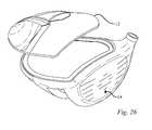
- FIG. 25is a perspective view of one embodiment of a golf club head.
- FIG. 26is a perspective view of one embodiment of a golf club head.
- FIG. 27is a bottom plan view of one embodiment of a golf club head.
- FIG. 28is a bottom plan view of one embodiment of a golf club head.
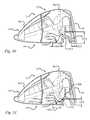
- FIG. 29is a cross-sectional view of one embodiment of a golf club head.
- FIG. 30is a cross-sectional view of one embodiment of a golf club head.
- FIG. 31is a cross-sectional view of one embodiment of a golf club head.
- FIG. 32is a cross-sectional view of one embodiment of a golf club head.
- FIG. 33is a cross-sectional view of one embodiment of a golf club head.
- FIG. 34is an enlarged cross-sectional view of a golf club head having a removable shaft, in accordance with another embodiment.
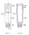
- FIG. 35is a front elevation view of a shaft sleeve of the assembly shown in FIG. 28 .
- FIG. 36is a cross-sectional view of a shaft sleeve of the assembly shown in FIG. 28 .
- FIG. 37is an exploded view of a golf club head, according to another embodiment.
- FIG. 38Ais a bottom view of the golf club head of FIG. 31 .
- FIG. 38Bis an enlarged bottom view of a portion of the golf club head of FIG. 31 .
- FIG. 38Cis a cross-sectional view of the golf club head of FIG. 32A , taken along line C-C.
- FIG. 38Dis a cross-sectional view of the golf club head of FIG. 32A , taken along line D-D.
- FIG. 38Eis a cross-sectional view of the golf club head of FIG. 32A , taken along line E-E.
- FIG. 39is a cross-sectional view of one embodiment of a golf club head.
- golf club headsfor metalwood type golf clubs, including drivers, fairway woods, rescue clubs, hybrid clubs, and the like.
- Several of the golf club headsincorporate features that provide the golf club heads and/or golf clubs with increased moments of inertia and low centers of gravity, centers of gravity located in preferable locations, improved club head and face geometries, increased sole and lower face flexibility, desirable club head tuning, higher coefficients or restitution (“COR”) and characteristic times (“CT”), and/or decreased backspin rates relative to other golf club heads that have come before.
- CORcoefficients or restitution
- CTcharacteristic times
- Club heads and many of their physical characteristics disclosed hereinwill be described using “normal address position” as the club head reference position, unless otherwise indicated.
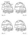
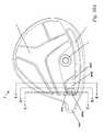
- FIGS. 1-3illustrate one embodiment of a golf club head at normal address position.
- FIG. 1illustrates a top plan view of the club head 2
- FIG. 2illustrates a side elevation view from the toe side of the club head 2
- FIG. 3illustrates a front elevation view.
- the club head 2includes a hosel 20 and a ball striking club face 18 .
- the club head 2rests on the ground plane 17 , a plane parallel to the ground.
- normal address positionmeans the club head position wherein a vector normal to the club face 18 substantially lies in a first vertical plane (i.e., a vertical plane is perpendicular to the ground plane 17 ), the centerline axis 21 of the club shaft substantially lies in a second vertical plane, and the first vertical plane and the second vertical plane substantially perpendicularly intersect.
- a golf club headsuch as the golf club head 2 , includes a hollow body 10 defining a crown portion 12 , a sole portion 14 and a skirt portion 16 .
- a striking face, or face portion, 18attaches to the body 10 .
- the body 10can include a hosel 20 , which defines a hosel bore 24 adapted to receive a golf club shaft.
- the body 10further includes a heel portion 26 , a toe portion 28 , a front portion 30 , and a rear portion 32 .
- the club head 2also has a volume, typically measured in cubic-centimeters (cm 3 ), equal to the volumetric displacement of the club head 2 , assuming any apertures are sealed by a substantially planar surface. (See United States Golf Association “Procedure for Measuring the Club Head Size of Wood Clubs,” Revision 1.0, Nov. 21, 2003). In some implementations, the golf club head 2 has a volume between approximately 120 cm 3 and approximately 460 cm 3 , and a total mass between approximately 185 g and approximately 245 g. Additional specific implementations having additional specific values for volume and mass are described elsewhere herein.
- FIGS. 11-22 and 39illustrate embodiments of a cross-sectional view of the golf club head of FIG. 1 taken along line 11 - 11 of FIG. 2 showing internal features of the golf club head.
- FIGS. 9-10 and 29-31illustrate embodiments of a cross-sectional view of the golf club head of FIG. 1 taken along line 9 - 9 of FIG. 1 showing internal features of the golf club head.
- FIG. 23illustrates an embodiment of a cross-sectional view of the golf club head of FIG. 1 taken along line 23 - 23 of FIG.
- solemeans a lower portion of the club head 2 extending upwards from a lowest point of the club head when the club head is at normal address position.
- the sole 14extends upwardly from the lowest point of the golf club body 10 a shorter distance than the sole 14 of golf club head 2 .
- the sole 14can define a substantially flat portion extending substantially horizontally relative to the ground 17 when in normal address position.
- the bottommost portion of the sole 14extends substantially parallel to the ground 17 between approximately 5% and approximately 70% of the depth Dch of the golf club body 10 .
- an adjustable mechanismis provided on the sole 14 to “decouple” the relationship between face angle and hosel/shaft loft, i.e., to allow for separate adjustment of square loft and face angle of a golf club.
- some embodiments of the golf club head 2include an adjustable sole portion that can be adjusted relative to the club head body 2 to raise and lower the rear end of the club head relative to the ground. Further detail concerning the adjustable sole portion is provided in U.S. patent application Ser. No. 14/734,181, which is incorporated herein by reference.
- skirtmeans a side portion of the club head 2 between the crown 12 and the sole 14 that extends across a periphery 34 of the club head, excluding the face 18 , from the toe portion 28 , around the rear portion 32 , to the heel portion 26 .
- “striking surface”means a front or external surface of the striking face 18 configured to impact a golf ball (not shown).
- the striking face or face portion 18can be a striking plate attached to the body 10 using conventional attachment techniques, such as welding, as will be described in more detail below.
- the striking surface 22can have a bulge and roll curvature.
- the average face thickness for the illustrated embodimentis in the range of from about 1.0 mm to about 4.5 mm, such as between about 2.0 mm and about 2.2 mm.
- the body 10can be made from a metal alloy (e.g., an alloy of titanium, an alloy of steel, an alloy of aluminum, and/or an alloy of magnesium), a composite material, such as a graphitic composite, a ceramic material, or any combination thereof (e.g., a metallic sole and skirt with a composite, magnesium, or aluminum crown).
- a metal alloye.g., an alloy of titanium, an alloy of steel, an alloy of aluminum, and/or an alloy of magnesium
- a composite materialsuch as a graphitic composite, a ceramic material, or any combination thereof
- the crown 12 , sole 14 , and skirt 16can be integrally formed using techniques such as molding, cold forming, casting, and/or forging and the striking face 18 can be attached to the crown, sole and skirt by known means.
- the body 10can be formed from a cup-face structure, with a wall or walls extending rearward from the edges of the inner striking face surface and the remainder of the body formed as a separate piece that is joined to the walls of the cup-face by welding, cementing, adhesively bonding, or other technique known to those skilled in the art.
- the ideal impact location 23 of the golf club head 2is disposed at the geometric center of the face 18 .
- the ideal impact location 23is typically defined as the intersection of the midpoints of a height Hss and a width Wss of the face 18 . Both Hss and Wss are determined using the striking face curve Sss.
- the striking face curveis bounded on its periphery by all points where the face transitions from a substantially uniform bulge radius (face heel-to-toe radius of curvature) and a substantially uniform roll radius (face crown-to-sole radius of curvature) to the body.
- Hssis the distance from the periphery proximate to the sole portion of Sss to the periphery proximate to the crown portion of Sss measured in a vertical plane (perpendicular to ground) that extends through the geometric center of the face 18 (e.g., this plane is substantially normal to the x-axis). Further, as seen in FIGS. 8 and 10 , the face 18 has a top edge elevation, Hte, measured from the ground plane.
- Wssis the distance from the periphery proximate to the heel portion of Sss to the periphery proximate to the toe portion of Sss measured in a horizontal plane (e.g., substantially parallel to ground) that extends through the geometric center of the face (e.g., this plane is substantially normal to the z-axis).
- a horizontal planee.g., substantially parallel to ground
- Wsswidth between approximately 60 mm and approximately 120 mm.
- the face 18has a height Hss of approximately 26 mm, width Wss of approximately 71 mm, and total striking surface area of approximately 2050 mm 2 . Additional specific implementations having additional specific values for face height Hss, face width Wss, and total striking surface area are described elsewhere herein.
- the striking face 18is made of a composite material such as described in U.S. patent application Ser. No. 14/154,513, which is incorporated herein by reference.
- the striking face 18is made from a metal alloy (e.g., an alloy of titanium, steel, aluminum, and/or magnesium), ceramic material, or a combination of composite, metal alloy, and/or ceramic materials.
- a metal alloye.g., an alloy of titanium, steel, aluminum, and/or magnesium
- ceramic materiale.g., aluminum, and/or magnesium
- ceramic materiale.g., aluminum, and/or magnesium
- ceramic materiale.g., aluminum, and/or magnesium
- a combination of composite, metal alloy, and/or ceramic materialse.g., aluminum, and/or magnesium
- titanium alloysinclude 3-2.5, 6-4, SP700, 15-3-3-3, 10-2-3, or other alpha/near alpha, alpha-beta, and beta/near beta titanium alloys.
- steel alloysinclude 304, 410
- the striking face 18is formed of a maraging steel, a maraging stainless steel, or a precipitation-hardened (PH) steel or stainless steel.
- maraging steelshave high strength, toughness, and malleability. Being low in carbon, they derive their strength from precipitation of inter-metallic substances other than carbon.
- the principle alloying elementis nickel (15% to nearly 30%).
- Other alloying elements producing inter-metallic precipitates in these steelsinclude cobalt, molybdenum, and titanium.
- a non-stainless maraging steelcontains about 17-19% nickel, 8-12% cobalt, 3-5% molybdenum, and 0.2-1.6% titanium.
- Maraging stainless steelshave less nickel than maraging steels, but include significant amounts of chromium to prevent rust.
- NiMark® Alloy 300having a composition that includes the following components: nickel (18.00 to 19.00%), cobalt (8.00 to 9.50%), molybdenum (4.70 to 5.10%), titanium (0.50 to 0.80%), manganese (maximum of about 0.10%), silicon (maximum of about 0.10%), aluminum (about 0.05 to 0.15%), calcium (maximum of about 0.05%), zirconium (maximum of about 0.03%), carbon (maximum of about 0.03%), phosphorus (maximum of about 0.010%), sulfur (maximum of about 0.010%), boron (maximum of about 0.003%), and iron (balance).
- Non-stainless maraging steel suitable for use in forming a striking face 18includes NiMark® Alloy 250, having a composition that includes the following components: nickel (18.00 to 19.00%), cobalt (7.00 to 8.00%), molybdenum (4.70 to 5.00%), titanium (0.30 to 0.50%), manganese (maximum of about 0.10%), silicon (maximum of about 0.10%), aluminum (about 0.05 to 0.15%), calcium (maximum of about 0.05%), zirconium (maximum of about 0.03%), carbon (maximum of about 0.03%), phosphorus (maximum of about 0.010%), sulfur (maximum of about 0.010%), boron (maximum of about 0.003%), and iron (balance).
- Other maraging steelshaving comparable compositions and material properties may also be suitable for use.
- a golf club headincludes a body 10 that is formed from a metal (e.g., steel), a metal alloy (e.g., an alloy of titanium, an alloy of aluminum, and/or an alloy of magnesium), a composite material, such as a graphitic composite, a ceramic material, or any combination thereof, as described above.
- a striking face 18is attached to the body 10 , and is formed from a non-stainless steel, such as one of the maraging steels described above.
- a golf club headincludes a body 10 that is formed from a stainless steel (e.g., Custom 450® Stainless) and a striking face 18 that is formed from a non-stainless maraging steel (e.g., NiMark® Alloy 300).
- a stainless steele.g., Custom 450® Stainless
- a non-stainless maraging steele.g., NiMark® Alloy 300
- a golf club headincludes a body 10 that is formed from a non-stainless steel, such as one of the maraging steels described above.
- a striking face 18is attached to the body 10 , and is also formed from a non-stainless steel, such as one of the maraging steels described above.
- a golf club headincludes a body 10 and a striking face 18 that are each formed from a non-stainless maraging steel (e.g., NiMark® Alloy 300 or NiMark® Alloy 250).
- the club head 2When at normal address position as seen in FIG. 3 , the club head 2 is disposed at a lie-angle 19 relative to the club shaft axis 21 and the club face has a loft angle 15 .
- the lie-angle 19refers to the angle between the centerline axis 21 of the club shaft and the ground plane 17 at normal address position.
- Lie angle for a fairway woodtypically ranges from about 54 degrees to about 62 degrees, most typically about 56 degrees to about 60 degrees.
- loft-angle 15refers to the angle between a tangent line 27 to the club face 18 and a vector normal to the ground plane 29 at normal address position.
- Loft angle for a driveris typically greater than about 7 degrees
- the loft angle for a fairway woodis typically greater than about 13 degrees.
- loft for a drivertypically ranges from about 7 degrees to about 13 degrees
- the loft for a fairway woodtypically ranges from about 13 degrees to about 28 degrees, and more preferably from about 13 degrees to about 22 degrees.
- a club shaftis received within the hosel bore 24 and is aligned with the centerline axis 21 .
- a connection assemblyis provided that allows the shaft to be easily disconnected from the club head 2 .
- the connection assemblyprovides the ability for the user to selectively adjust the loft-angle 15 and/or lie-angle 19 of the golf club.
- a sleeveis mounted on a lower end portion of the shaft and is configured to be inserted into the hosel bore 24 .
- the sleevehas an upper portion defining an upper opening that receives the lower end portion of the shaft, and a lower portion having a plurality of longitudinally extending, angularly spaced external splines located below the shaft and adapted to mate with complimentary splines in the hosel opening 24 .
- the lower portion of the sleevedefines a longitudinally extending, internally threaded opening adapted to receive a screw for securing the shaft assembly to the club head 2 when the sleeve is inserted into the hosel opening 24 .
- a club head origin coordinate systemcan be defined such that the location of various features of the club head (including, e.g., a club head center-of-gravity (CG) 50 ) can be determined.
- a club head origin 60is illustrated on the club head 2 positioned at the ideal impact location 23 , or geometric center, of the face 18 .
- the head origin coordinate system defined with respect to the head origin 60includes three axes: a z-axis 65 extending through the head origin 60 in a generally vertical direction relative to the ground 17 when the club head 2 is at normal address position; an x-axis 70 extending through the head origin 60 in a toe-to-heel direction generally parallel to the face 18 , e.g., generally tangential to the face 18 at the ideal impact location 23 , and generally perpendicular to the z-axis 65 ; and a y-axis 75 extending through the head origin 60 in a front-to-back direction and generally perpendicular to the x-axis 70 and to the z-axis 65 .
- the x-axis 70 and the y-axis 75both extend in generally horizontal directions relative to the ground 17 when the club head 2 is at normal address position.
- the x-axis 70extends in a positive direction from the origin 60 to the heel 26 of the club head 2 .
- the y-axis 75extends in a positive direction from the origin 60 towards the rear portion 32 of the club head 2 .
- the z-axis 65extends in a positive direction from the origin 60 towards the crown 12 .
- An alternative, above ground, club head coordinate systemplaces the origin 60 at the intersection of the z-axis 65 and the ground plane 17 , providing positive z-axis coordinates for every club head feature.
- “Zup”means the CG z-axis location determined according to the above ground coordinate system. Zup generally refers to the height of the CG 50 above the ground plane 17 .
- the golf club headcan have a CG with an x-axis coordinate between approximately ⁇ 2.0 mm and approximately 6.0 mm, such as between approximately ⁇ 2.0 mm and approximately 3.0 mm, a y-axis coordinate between approximately 15 mm and approximately 40 mm, such as between approximately 20 mm and approximately 30 mm, or between approximately 23 mm and approximately 28 mm, and a z-axis coordinate between approximately 0.0 mm and approximately ⁇ 12.0 mm, such as between approximately ⁇ 1.0 mm and approximately ⁇ 9.0 mm, or between approximately ⁇ 1.0 mm and approximately ⁇ 5.0 mm.
- a z-axis coordinate between about 0.0 mm and about ⁇ 12.0 mmprovides a Zup value of between approximately 10 mm and approximately 30 mm. Additional specific implementations having additional specific values for the CG x-axis coordinate, CG y-axis coordinate, CG z-axis coordinate, and Zup are described elsewhere herein.
- Another alternative coordinate systemuses the club head center-of-gravity (CG) 50 as the origin when the club head 2 is at normal address position.
- CGcenter-of-gravity
- Each center-of-gravity axispasses through the CG 50 .
- the CG x-axis 90passes through the center-of-gravity 50 substantially parallel to the ground plane 17 and generally parallel to the origin x-axis 70 when the club head is at normal address position.
- the CG y-axis 95passes through the center-of-gravity 50 substantially parallel to the ground plane 17 and generally parallel to the origin y-axis 75
- the CG z-axis 85passes through the center-of-gravity 50 substantially perpendicular to the ground plane 17 and generally parallel to the origin z-axis 65 when the club head is at normal address position.
- golf club head moments of inertiaare typically defined about the three CG axes that extend through the golf club head center-of-gravity 50 .
- the golf club head CG yz-planeis a plane defined by the golf club head CG y-axis 95 and the golf club head CG z-axis 85 .
- the moment of inertia about the CG z-axisis an indication of the ability of a golf club head to resist twisting about the CG z-axis. Greater moments of inertia about the CG z-axis (Izz) provide the golf club head 2 with greater forgiveness on toe-ward or heel-ward off-center impacts with a golf ball. In other words, a golf ball hit by a golf club head 2 on a location of the striking face 18 between the toe 28 and the ideal impact location 23 tends to cause the golf club head to twist rearwardly and the golf ball to draw (e.g., to have a curving trajectory from right-to-left for a right-handed swing).
- a golf ball hit by a golf club head 2 on a location of the striking face 18 between the heel 26 and the ideal impact location 23causes the golf club head 2 to twist forwardly and the golf ball to slice (e.g., to have a curving trajectory from left-to-right for a right-handed swing).
- Increasing the moment of inertia about the CG z-axis (Izz)reduces forward or rearward twisting of the golf club head, reducing the negative effects of heel or toe mis-hits.
- the golf club head CG xz-planeis a plane defined by the golf club head CG x-axis 90 and the golf club head CG z-axis 85 .
- the CG xy-planeis a plane defined by the golf club head CG x-axis 90 and the golf club head CG y-axis 95 .
- the moment of inertia about the CG z-axisis an indication of the ability of a golf club head to resist twisting about the CG z-axis
- the moment of inertia about the CG x-axisis an indication of the ability of the golf club head to resist twisting about the CG x-axis.
- Greater moments of inertia about the CG x-axis (Ixx)improve the forgiveness of the golf club head 2 on high and low off-center impacts with a golf ball. In other words, a golf ball hit by a golf club head 2 on a location of the striking surface 18 above the ideal impact location 23 causes the golf club head 2 to twist upwardly and the golf ball to have a higher trajectory than desired.
- a golf ball hit by a golf club head 2 on a location of the striking face 18 below the ideal impact location 23causes the golf club head 2 to twist downwardly and the golf ball to have a lower trajectory than desired.
- Increasing the moment of inertia about the CG x-axis (Ixx)reduces upward and downward twisting of the golf club head 2 , reducing the negative effects of high and low mis-hits.
- Desired club head mass moments of inertia, club head center-of-gravity locations, and other mass properties of a golf club headcan be attained by distributing club head mass to particular locations.
- Discretionary massgenerally refers to the mass of material that can be removed from various structures providing mass that can be distributed elsewhere for tuning one or more mass moments of inertia and/or locating the club head center-of-gravity.
- Club head wallsprovide one source of discretionary mass.
- a reduction in wall thicknessreduces the wall mass and provides mass that can be distributed elsewhere.
- one or more walls of the club headcan have a thickness (constant or average) less than approximately 0.7 mm, such as between about 0.55 mm and about 0.65 mm.
- the crown 12can have a thickness (constant or average) of approximately 0.60 mm or approximately 0.65 mm throughout more than about 70% of the crown, with the remaining portion of the crown 12 having a thickness (constant or average) of approximately 0.76 mm or approximately 0.80 mm. See for example FIG.
- FIG. 9which illustrates a back crown thickness 905 of about 0.60 mm and a front crown thickness 901 of about 0.76 mm.
- the skirt 16can have a similar thickness and the wall of the sole 14 can have a thickness of between approximately 0.6 mm and approximately 2.0 mm.
- many conventional club headshave crown wall thicknesses in excess of about 0.75 mm, and some in excess of about 0.85 mm.
- Thin walls, particularly a thin crown 12provide significant discretionary mass compared to conventional club heads.
- a club head 2 made from an alloy of steelcan achieve about 4 grams of discretionary mass for each 0.1 mm reduction in average crown thickness.
- a club head 2 made from an alloy of titaniumcan achieve about 2.5 grams of discretionary mass for each 0.1 mm reduction in average crown thickness.
- Discretionary mass achieved using a thin crown 12e.g., less than about 0.65 mm, can be used to tune one or more mass moments of inertia and/or center-of-gravity location.
- a club head body 10can be formed from an alloy of steel or an alloy of titanium.
- Thin wall investment castingsuch as gravity casting in air for alloys of steel and centrifugal casting in a vacuum chamber for alloys of titanium, provides one method of manufacturing a club head body with one or more thin walls.
- Various approachescan be used for positioning discretionary mass within a golf club head 2 .
- many club heads 2have integral sole weight pads cast into the head 2 at predetermined locations that can be used to lower, to move forward, to move rearward, or otherwise to adjust the location of the club head's center-of-gravity.
- epoxycan be added to the interior of the club head 2 through the club head's hosel opening to obtain a desired weight distribution.
- weights formed of high-density materialscan be attached to the sole, skirt, and other parts of a club head.
- the golf club head 2can define one or more weight ports 40 formed in the body 10 that are configured to receive one or more weights.
- one or more weight ports 40can be disposed in the crown 12 , skirt 16 and/or sole 14 .
- the weight port 40can have any of a number of various configurations to receive and retain any of a number of weights or weight assemblies, such as described in U.S. Pat. Nos. 7,407,447 and 7,419,441, which are incorporated herein by reference.
- the weight port 40may provide the capability of a weight to be removably engageable with the sole 14 .
- a single weight port 40 and engageable weightis provided, while in others, a plurality of weight ports 40 (e.g., two, three, four, or more) and engageable weights are provided.
- the weight port 40defines internal threads that correspond to external threads formed on the weight. Weights and/or weight assemblies configured for weight ports in the sole can vary in mass from about 0.5 grams to about 20 grams.
- Inclusion of one or more weights in the weight port(s) 40provides a customizable club head mass distribution, and corresponding mass moments of inertia and center-of-gravity 50 locations. Adjusting the location of the weight port(s) 40 and the mass of the weights and/or weight assemblies provides various possible locations of center-of-gravity 50 and various possible mass moments of inertia using the same club head 2 .
- a playable fairway wood club headcan have a low, rearward center-of-gravity. Placing one or more weight ports 40 and weights rearward in the sole helps desirably locate the center-of-gravity.
- a center of gravity of the weightis preferably located rearward of a midline of the golf club head along the y-axis 75 , such as, for example, within about 40 mm of the rear portion 32 of the club head, or within about 30 mm of the rear portion 32 of the club head, or within about 20 mm of the rear portion of the club head.
- a playable fairway wood club headcan have a center-of-gravity that is located to provide a preferable center-of-gravity projection on the striking surface 22 of the club head.
- one or more weight ports 40 and weightsare placed in the sole portion 14 forward of a midline of the golf club head along the y-axis 75 .
- a center of gravity of one or more weights placed in the sole portion 14 of the club headis located within about 30 mm of the nearest portion of the forward edge of the sole, such as within about 20 mm of the nearest portion of the forward edge of the sole, or within about 15 mm of the nearest portion of the forward edge of the sole, or within about 10 mm of the nearest portion of the forward edge of the sole.
- other methodse.g., using internal weights attached using epoxy or hot-melt glue
- use of a weight port and/or integrally molding a discretionary weight into the body 10 of the club headreduces undesirable effects on the audible tone emitted during impact with a golf ball.
- the club head center-of-gravity location 50can also be tuned by modifying the club head external envelope.
- the club head 2has a maximum club head height Hch defined as the maximum above ground z-axis coordinate of the outer surface of the crown 12 .
- a maximum club head width Wchcan be defined as the distance between the maximum extents of the heel and toe portions 26 , 28 of the body measured along an axis parallel to the x-axis when the club head 2 is at normal address position and a maximum club head depth Dch, or length, defined as the distance between the forwardmost and rearwardmost points on the surface of the body 10 measured along an axis parallel to the y-axis when the club head 2 is at normal address position.
- the height and width of club head 2should be measured according to the USGA “Procedure for Measuring the Clubhead Size of Wood Clubs” Revision 1.0.
- the heel portion 28 of the club head 2is broadly defined as the portion of the club head 2 from a vertical plane passing through the origin y-axis 75 toward the hosel 20 , while the toe portion 26 is that portion of the club head 2 on the opposite side of the vertical plane passing through the origin y-axis 75 .
- the golf club head 2has a height Hch less than approximately 55 mm. In some embodiments, the club head 2 has a height Hch less than about 50 mm. For example, some implementations of the golf club head 2 have a height Hch less than about 45 mm. In other implementations, the golf club head 2 has a height Hch less than about 42 mm. Still other implementations of the golf club head 2 have a height Hch less than about 40 mm. Further, some examples of the golf club head 2 have a depth Dch greater than approximately 75 mm. In some embodiments, the club head 2 has a depth Dch greater than about 85 mm. For example, some implementations of the golf club head 2 have a depth Dch greater than about 95 mm. In other implementations, as discussed in more detail below, the golf club head 2 can have a depth Dch greater than about 100 mm.
- Golf club head “forgiveness”generally describes the ability of a club head to deliver a desirable golf ball trajectory despite a mis-hit (e.g., a ball struck at a location on the striking face 18 other than the ideal impact location 23 ).
- a mis-hite.g., a ball struck at a location on the striking face 18 other than the ideal impact location 23 .
- large mass moments of inertiacontribute to the overall forgiveness of a golf club head.
- a low center-of-gravityimproves forgiveness for golf club heads used to strike a ball from the turf by giving a higher launch angle and a lower spin trajectory.
- Providing a rearward center-of-gravityreduces the likelihood of a slice or fade for many golfers. Accordingly, forgiveness of club heads, such as the club head 2 , can be improved using the techniques described above to achieve high moments of inertia and low center-of-gravity compared to conventional fairway wood golf club heads.
- a club head 2 with a crown thickness less than about 0.65 mm throughout at least about 70% of the crowncan provide significant discretionary mass.
- a 0.60 mm thick crowncan provide as much as about 8 grams of discretionary mass compared to a 0.80 mm thick crown.
- the large discretionary masscan be distributed to improve the mass moments of inertia and desirably locate the club head center-of-gravity.
- discretionary massshould be located sole-ward rather than crown-ward to maintain a low center-of-gravity, forward rather than rearward to maintain a forwardly positioned center of gravity, and rearward rather than forward to maintain a rearwardly positioned center-of-gravity.
- discretionary massshould be located far from the center-of-gravity and near the perimeter of the club head to maintain high mass moments of inertia.
- a comparatively forgiving golf club head 2 for a fairway woodcan combine an overall club head height (Hch) of less than about 46 mm and an above ground center-of-gravity location, Zup, less than about 19 mm. Some examples of the club head 2 provide an above ground center-of-gravity location, Zup, less than about 16 mm.
- a thin crown 12 as described aboveprovides sufficient discretionary mass to allow the club head 2 to have a volume less than about 240 cm 3 and/or a front to back depth (DCH) greater than about 85 mm.
- discretionary masscan be distributed to provide a mass moment of inertia about the CG z-axis 85 , Izz, greater than about 300 kg-mm 2 .
- the mass moment of inertia about the CG z-axis 85 , Izzcan be greater than about 320 kg-mm 2 , such as greater than about 340 kg-mm 2 or greater than about 360 kg-mm 2 .
- Distribution of the discretionary masscan also provide a mass moment of inertia about the CG x-axis 90 , Ixx, greater than about 150 kg-mm 2 .
- the mass moment of inertia about the CG x-axis 85 , Ixxcan be greater than about 170 kg-mm 2 , such as greater than about 190 kg-mm 2 .
- some examples of a forgiving club head 2combine an above ground center-of-gravity location, Zup, less than about 19 mm and a high moment of inertia about the CG z-axis 85 , Izz.
- the moment of inertia about the CG z-axis 85 , Izz, specified in units of kg-mm 2together with the above ground center-of-gravity location, Zup, specified in units of millimeters (mm), can satisfy the relationship Izz ⁇ 13 ⁇ Zup+105.
- some forgiving fairway wood club headshave a moment of inertia about the CG z-axis 85 , Izz, and a moment of inertia about the CG x-axis 90 , Ixx, specified in units of kg-mm 2 , together with an above ground center-of-gravity location, Zup, specified in units of millimeters, that satisfy the relationship Ixx+Izz ⁇ 20 ⁇ Zup+165.
- a forgiving fairway wood club headcan have a moment of inertia about the CG x-axis, Ixx, specified in units of kg-mm 2 , and, an above ground center-of-gravity location, Zup, specified in units of millimeters, that together satisfy the relationship Ixx ⁇ 7 ⁇ Zup+60.
- CORcoefficient of restitution
- CTCharacteristic Time
- the location of the center of gravityalso has a significant effect on the COR of a golf club head.
- a given golf club head having a given CGwill have a projected center of gravity or “balance point” or “CG projection” that is determined by an imaginary line passing through the CG and oriented normal to the striking face 18 .
- the location where the imaginary line intersects the striking face 18is the CG projection, which is typically expressed as a distance above or below the center of the striking face 18 .
- the CG projection above centerface of a golf club headcan be measured directly, or it can be calculated from several measurable properties of the club head.
- Fairway wood shotstypically involve impacts that occur below the center of the face, so ball speed and launch parameters are often less than ideal. This results because most fairway wood shots are from the ground and not from a tee, and most golfers have a tendency to hit their fairway wood ground shots low on the face of the club head. Maximum ball speed is typically achieved when the ball is struck at the location on the striking face where the COR is greatest.
- the location where the COR is greatestis the same as the location of the CG projection on the striking surface. This location, however, is generally higher on the striking surface than the below center location of typical ball impacts during play.
- greater shot distanceis achieved by configuring the club head to have a CG projection that is located near to the center of the striking surface of the golf club head.
- the golf club head 2has a CG projection that is less than about 2.0 mm from the center of the striking surface of the golf club head, i.e. ⁇ 2.0 mm ⁇ CG projection ⁇ 2.0 mm.
- some implementations of the golf club head 2have a CG projection that is less than about 1.0 mm from the center of the striking face of the golf club head (i.e., ⁇ 1.0 mm ⁇ CG projection ⁇ 1.0 mm), such as about 0.7 mm or less from the center of the striking surface of the golf club head (i.e., ⁇ 0.7 mm ⁇ CG projection ⁇ 0.7 mm), or such as about 0.5 mm or less from the center of the striking surface of the golf club head (i.e., ⁇ 0.5 mm ⁇ CG projection ⁇ 0.5 mm).
- the golf club head 2has a CG projection that is less than about 2.0 mm (i.e., the CG projection is below about 2.0 mm above the center of the striking face), such as less than about 1.0 mm (i.e., the CG projection is below about 1.0 mm above the center of the striking face), or less than about 0.0 mm (i.e., the CG projection is below the center of the striking face), or less than about ⁇ 1.0 mm (i.e., the CG projection is below about 1.0 mm below the center of the striking face). In each of these embodiments, the CG projection is located above the bottom of the striking face.
- an optimal location of the CG projectionis related to the loft 15 of the golf club head.
- the golf club head 2has a CG projection of about 3 mm or less above the center of the striking face for club heads where the loft angle is at least 15.8 degrees.
- greater shot distanceis achieved if the CG projection is about 1.4 mm or less above the center of the striking face for club heads where the loft angle is less than 15.8 degrees.
- the golf club head 2has a CG projection that is below about 3 mm above the center of the striking face for club heads where the loft angle 15 is more than about 16.2 degrees, and has a CG projection that is below about 2.0 mm above the center of the striking face for club heads where the loft angle 15 is 16.2 degrees or less. In still other embodiments, the golf club head 2 has a CG projection that is below about 3 mm above the center of the striking face for golf club heads where the loft angle 15 is more than about 16.2 degrees, and has a CG projection that is below about 1.0 mm above the center of the striking face for club heads where the loft angle 15 is 16.2 degrees or less.
- the golf club head 2has a CG projection that is below about 3 mm above the center of the striking face for golf club heads where the loft angle 15 is more than about 16.2 degrees, and has a CG projection that is below about 1.0 mm above the center of the striking face for club heads where the loft angle 15 is between about 14.5 degrees and about 16.2 degrees.
- the CG projectionis located above the bottom of the striking face. Further, greater initial ball speeds and lower backspin rates are achieved with the lower CG projections.
- a golf club head Characteristic Timecan be described as a numerical characterization of the flexibility of a golf club head striking face.
- the CTmay also vary at points distant from the center of the striking face, but may not vary greater than approximately 20% of the CT as measured at the center of the striking face.
- the CT values for the golf club heads described in the present applicationwere calculated based on the method outlined in the USGA “Procedure for Measuring the Flexibility of a Golf Clubhead,” Revision 2.0, Mar. 25, 2005, which is incorporated by reference herein in its entirety. Specifically, the method described in the sections entitled “3. Summary of Method,” “5. Testing Apparatus Set-up and Preparation,” “6. Club Preparation and Mounting,” and “7. Club Testing” are exemplary sections that are relevant.
- the characteristic timeis the time for the velocity to rise from 5% of a maximum velocity to 95% of the maximum velocity under the test set forth by the USGA as described above.
- the coefficient of restitution (COR) of a golf clubmay be increased by increasing the height Hs, of the striking face 18 and/or by decreasing the thickness of the striking face 18 of a golf club head 2 .
- increasing the face heightmay be considered undesirable because doing so will potentially cause an undesirable change to the mass properties of the golf club (e.g., center of gravity location) and to the golf club's appearance.
- FIGS. 1-39show golf club heads that provide increased COR by introducing a flexible channel 212 to increase or enhance the perimeter flexibility of the striking face 18 of the golf club without necessarily increasing the height or decreasing the thickness of the striking face 18 .
- the flexible channel 212allows for improved performance on mis-hits by increasing the coefficient of restitution (COR) and Characteristic Time (CT) across the face 18 and not just at the center of the face 18 , and selectively reducing the amount of spin imparted on a golf ball at impact.
- CORcoefficient of restitution
- CTCharacteristic Time
- the golf club head 2may include a sole 14 defining a bottom portion of the club head 2 , a crown 12 defining a top portion of the club head 2 , a skirt portion 16 defining a periphery of the club head 2 between the sole 14 and crown 12 , a face 18 defining a forward portion of the club head 2 , and a hosel 20 defining a hosel bore 24 , thereby defining an interior cavity, or hollow body 10 .
- Some club head 2 embodimentsinclude a flexible channel 212 positioned in the sole 14 of the club head 2 and extending into the interior cavity, or hollow body 10 , of the club head 2 , and in some embodiments the channel 212 extends substantially in a heel-to-toe direction and has a channel length Lg, a channel width Wg, a channel depth Dg, a channel wall thickness 221 , an internal channel structure elevation 224 , and a channel setback distance 223 from a leading edge of the club head 2 .
- the leading edgeis the forwardmost portion of the club head 2 in a particular vertical section that extends in a face-to-rear direction through the width of the striking face Wss, and the leading edge varies across the width of the striking face Wss.
- the channel setback distance 223may vary across the width of the striking face Wss, although some embodiments may have a constant channel setback distance 223 .
- the club head 2will have a maximum channel setback distance 223 , which in the embodiment of FIG. 4 occurs near the center of the face 18 , and a minimum channel setback distance 223 , which occurs toward the heel 26 or toe 28 of the club head 2 in the embodiment of FIG.
- the minimum channel setback distance 223is less than the maximum channel width Wg, while an even further embodiment has a minimum channel setback distance 223 is less than 75% of the maximum channel width Wg, and an even further embodiment has a minimum channel setback distance 223 is 25-75% of the maximum channel width Wg.
- the minimum channel setback distance 223is less than 15 mm, while in a further embodiment the minimum channel setback distance 223 is less than 10 mm, while in an even further embodiment the minimum channel setback distance 223 is 3-8 mm.
- the maximum channel setback distance 223is less than 30 mm, while in a further embodiment the maximum channel setback distance 223 is less than 20 mm.
- While preferential face flexibility and durabilitymay be enhanced as the size of the channel 212 increases, along with the unique relationships disclosed herein, thereby reducing the stresses in the channel 212 , increasing the size of the channel 212 , particularly the channel depth Dg and channel width Wg, may produce less than desirable sound and vibration upon impact with a golf ball. Additional embodiments further improve the performance via a center-of-gravity CG that is low and forward in conjunction with the channel 212 , as well as aerodynamic embodiments having a particularly bulbous crown 12 which may include irregular contours and very thin areas, any of which may further heighten these less than desirable characteristics.
- Such undesirable attributes associated with the channel 212may be mitigated with the introduction of a channel tuning system 1100 , such as the embodiments seen in FIGS. 11-22 , and/or a body tuning system 1400 , as seen in FIG. 9 .
- the channel depth Dgis easily measure by filling the channel 212 with clay until the club head 2 has a smooth continuous exterior surface as if the channel 212 does not exist. A blade oriented in the front-to-back direction may then be inserted vertically to section the clay. The clay may then be removed and the vertical thickness measure to reveal the channel depth Dg at any point along the length of the channel 212 .
- the channel tuning system 1100may include a longitudinal channel tuning element 1200 and/or a sole engaging channel tuning element 1300 .
- the longitudinal channel running element 1200is in contact with the channel 212 and the sole engaging channel tuning element 1300 is in contact with the channel 212 ; which in one embodiment means that they are integrally cast with the channel 212 , while in another embodiment they are attached to the channel 212 via available joining methods including welding, brazing, and adhesive attachment.
- the longitudinal channel tuning element 1200extends along a portion of the length of the channel 212 , and in one embodiment it extends substantially in a heel-to-toe direction, which may be a linear fashion, a zig-zag or sawtooth type fashion, or a curved fashion.
- the longitudinal channel tuning element 1200has a longitudinal tuning element toe end 1210 , a longitudinal element heel end 1220 , a longitudinal tuning element length 1230 , a longitudinal tuning element height 1240 , a longitudinal tuning element width 1250 , a top edge elevation 1260 , and a lower edge elevation 1270 .
- the aforementioned undesirable attributes associated with the club head 2are reduced when the longitudinal tuning element length 1230 is greater than the maximum channel width Wg, and in another embodiment when the longitudinal tuning element length 1230 is greater than 50% of the channel length Lg, while in an even further embodiment the longitudinal tuning element length 1230 is greater than 75% of the channel length Lg.
- the longitudinal tuning element length 1230is measured in a straight line along the ground plane from a vertical projection of the longitudinal tuning element toe end 1210 on the ground plane to a vertical projection of the longitudinal element heel end 1220 on the ground plane, which is the same manner the channel length Lg is measured.
- tuning of the club head 2is further improved when, in at least one front-to-rear vertical section passing through the longitudinal channel tuning element 1200 , a portion of the longitudinal tuning element top edge elevation 1260 is greater than the internal channel structure elevation 224 , as seen in FIG. 29 .
- these unique embodiments and relationships among the channel 212 , the attributes of the channel tuning system 1100 , the aerodynamic crown, thicknesses, and the club head mass propertiesselectively mitigate the undesirable characteristics without unduly reducing the performance advantages associated with the channel 212 , aerodynamic and mass property features, or sacrificing the durability of the club head 2 .
- Unique placement of the longitudinal tuning element top edge elevation 224aids in tuning the channel 212 to achieve desirable sound and vibration upon the impact of the club head 2 with a golf ball while not significantly impacting the flexibility of the channel 212 or durability of the club head 2 .
- a portion of the longitudinal tuning element top edge elevation 1260is at least 10% greater than the internal channel structure elevation 224 , while in an even further embodiment a portion of the longitudinal tuning element top edge elevation 1260 is than the internal channel structure elevation 224 by a distance that is greater than the maximum channel wall thickness 221 .
- the prior embodimentsare directed to characteristics in at least one front-to-rear vertical section passing through the longitudinal channel tuning element 1200 , in further embodiments the relationships are true through at least 25% of the channel length (Lg), and in even further embodiments through at least 50% of the channel length (Lg), and at least 75% in yet another embodiment. Another embodiment, seen in FIG.
- the longitudinal tuning element top edge elevation 1260above the elevation of the ideal impact location 23 , while in another embodiment a portion of the longitudinal tuning element top edge elevation 1260 is greater than the Zup value.
- at least a portion of the longitudinal channel tuning element 1200is in contact with both the channel 212 and the hosel bore 24 , further tuning the club head 2 without unduly adding rigidity to the channel 212 .
- At least a portion of the longitudinal channel tuning element 1200is positioned along the top edge of the channel 212 , as seen in FIG. 10 , such as in at least one front-to-rear vertical section passing through the longitudinal channel tuning element 1200 the lower edge elevation 1270 is equal to the internal channel structure elevation 224 , seen in FIG. 29 . While the prior embodiment is directed to characteristics in at least one front-to-rear vertical section passing through the longitudinal channel tuning element 1200 , in further embodiments the relationships are true through at least 25% of the channel length Lg, and in even further embodiments through at least 50% of the channel length Lg, and at least 75% in yet another embodiment. As seen in FIG.
- the longitudinal channel tuning element 1200may be oriented substantially vertically from the channel 212 , oriented at an angle toward the rear of the club head 2 as seen in FIG. 29 , or even at an angle toward the face 18 , not shown but easily understood.
- a substantial vertical orientationreduces the impact that the longitudinal channel tuning element 1200 has on the stiffness of the channel 212 , and therefore in another embodiment the orientation is substantially vertical through at least 25% of the channel length Lg, and in even further embodiments through at least 50% of the channel length Lg, and at least 75% in yet another embodiment.
- the substantial vertical orientationaids in the manufacturability of the club head 2 and reduces the likelihood of adding areas of significantly increased rigidity in the channel 212 , and the associated peak stress throughout the channel 212 , thereby improving the durability of the club head 2 , which is also true for the disclosed sizes of the longitudinal channel tuning element, namely the longitudinal tuning element height 1240 , the longitudinal tuning element width 1250 , and the longitudinal tuning element length 1230 .
- a further embodimenthas a longitudinal tuning element height 1240 , seen in FIG. 32 , is at least 20% of the channel depth Dg in at least one front-to-rear vertical section passing through the longitudinal channel tuning element, while in a further embodiment this relationship is true throughout at least 25% of the channel length Lg, and in even further embodiments through at least 50% of the channel length Lg, and at least 75% in yet another embodiment.
- a further embodimentbalances the aforementioned tradeoff with the longitudinal tuning element height being 20-70% of the channel depth Dg throughout at least 50% of the longitudinal tuning element length 1230 .
- the longitudinal tuning element width 1250plays a role in balancing the benefits and negative effects of the longitudinal channel tuning element 1200 .
- at least a portion of the longitudinal channel tuning element 1200has a longitudinal tuning element width 1250 of less than the maximum channel wall thickness 221 .
- the longitudinal tuning element width 1250is less than the maximum channel wall thickness 221 throughout at least 50% of the longitudinal tuning element length 1230 , while in an even further embodiment this is true throughout at least 75% of the longitudinal tuning element length 1230 .
- the longitudinal tuning element width 1250is less than 70% of the maximum channel wall thickness 221 throughout at least 50% of the longitudinal tuning element length 1230 , while in an even further embodiment this is true throughout at least 75% of the longitudinal tuning element length 1230 . Yet an even further embodiment has at least a portion of the longitudinal tuning element width 1250 of less than 70% of the maximum channel wall thickness 221 . In a further embodiment the longitudinal tuning element width 1250 of 25-60% of the maximum channel wall thickness 221 throughout at least 50% of the longitudinal tuning element length 1230 , while in an even further embodiment this is true throughout at least 75% of the longitudinal tuning element length 1230 .
- the location of the longitudinal channel tuning element 1200plays a role in balancing the benefits and negative effects.
- the longitudinal channel tuning element 1200extends throughout a channel central region 225 , which in one embodiment is defined as the portion of the channel 212 within 1 ⁇ 2 inch on either side of the ideal impact location 23 .
- Deflection of the channel 212 in this channel central region 225is not as important to improving the performance of the club head 2 and therefore is a good location for a longitudinal channel tuning element 1200 to influence the tuning of the club head 2 while having minimal effect on enhanced performance associated with the channel 212 , which is also why further embodiments, described elsewhere in detail, have increased channel wall thickness 221 in the channel central region 225 .
- Another embodimentcapitalizes on tuning gains afforded by having at least a portion of the longitudinal channel tuning element 1200 is in contact with both the channel 212 and the hosel bore 24 , further tuning the club head 2 without unduly adding rigidity to the channel 212 , as seen in FIGS. 12 and 33 .
- An alternative embodimentis seen in FIG.
- the longitudinal channel tuning element 1200is located on the toe portion of the channel 212 .
- the channel 212extends high up the skirt portion 16 , as seen in FIG. 33 , and therefore enables the previously described embodiment in which a portion of the longitudinal tuning element top edge elevation 1260 is above the elevation of the ideal impact location 23 , and the embodiment having a portion of the longitudinal tuning element top edge elevation 1260 is greater than the Zup value.
- a common mishitinvolves striking the golf ball high on the toe portion of the face and these embodiments achieve preferential tuning so that the pitch and vibrations associated with such mishits is not as significantly different from impacts at the ideal impact location 23 as may be experienced with a club head 2 having a channel 212 without a channel tuning system 1100 .
- FIG. 14has a longitudinal channel tuning element 1200 on the toe side of the channel 212 , like the embodiment of FIG. 13 , and a second longitudinal channel tuning element 1280 on the heel side of the channel 212 , like the embodiment of FIG. 14 .
- Still further embodiments such as those seen in FIGS. 19-22have a longitudinal channel tuning element 1200 extending continuously from the heel to the toe of the channel 212 .
- the channel tuning system 1100may further includes a sole engaging channel tuning element 1300 in contact with the sole 14 and the channel 212 , seen best in FIGS. 15 and 10 , which may be in addition to, or in lieu of, the longitudinal channel tuning element 1200 .
- the sole engaging channel tuning element 1300has a face end 1310 , a rear end 1320 , a sole engaging tuning element length 1330 , seen in FIG. 15 , a sole engaging tuning element height 1340 , seen in FIG. 10 , a sole engaging tuning element width 1350 , seen in FIG. 16 , a sole engaging portion 1360 in contact with the sole 14 and having a sole engaging portion length 1362 , seen in FIG.
- the unique relationships disclosedstrike a delicate balance in reducing the undesirable attributes associated with the channel 212 with preferential tuning, while not significantly compromising the performance and flexibility of the channel 212 , as well as the durability of the club head 2 .
- the goalsare achieved with a sole engaging portion length 1362 is at least 50% of the maximum channel width Wg.
- a further embodimentachieves the goals when the sole engaging portion 1360 has a sole engaging tuning element height 1340 of at least 15% of the maximum channel depth Dg.
- another embodimentseen in FIG. 31 , has a channel engaging portion 1370 that extends up the channel 212 to a channel engaging portion elevation 1374 that is at least 50% of the channel depth Dg in the same vertical plane as the channel engaging portion 1370
- another embodimenthas a channel engaging portion 1370 that extends up the channel 212 to a channel engaging portion elevation 1374 that is at least 50-100% of the channel depth Dg in the same vertical plane as the channel engaging portion 1370 .
- the channel engaging portion 1370does not extend along more than 50% of the channel 212 , as also illustrated in FIG. 16 , in a face-to-rear vertical section, and serves to tune the club head 2 while also supporting the rear channel wall 218 , yet facilitating significant deflection of the channel 212 for improved performance.
- another embodimenthas a channel engaging portion 1370 that extends up the channel 212 to a channel engaging portion elevation 1374 greater than the internal channel structure elevation 224 , as seen in FIG. 30 . In fact in some embodiments such as that seen in FIGS.
- the channel engaging portion 1370extends all the way over the channel 212 , and in some embodiments engages a portion of the sole 14 between the channel 212 and the face 18 , as seen in FIG. 30 . In one such entirely over the channel embodiment the channel engaging portion 1370 is located in the channel central region 225 to have a significant influence on the tuning of the club head 2 while having minimal effect on enhanced performance associated with the channel 212 because the slight decrease in potential deflection of the channel 212 in the channel central region 225 is not as impactful on overall club head 2 performance.
- the channel engaging portion length 1372plays a role in achieving the goals without unduly limiting the performance benefits gained through the addition of the channel 212 .
- the channel engaging portion length 1372is greater than the maximum channel depth Dg.
- the channel engaging portion length 1372is measured along the intersection of the channel engaging portion 1370 and the channel 212 .
- the channel engaging portion length 1372is less than the sum of the maximum channel depth Dg and the maximum channel width Wg, further controlling the amount of rigidity that is added to the flexible channel 212 .
- the sole engaging portion length 1362is less than 150% of the maximum channel width Wg, thereby further controlling the amount of rigidity that is added to the channel 212 .
- the goalsare further enhanced when the sole engaging tuning element width 1350 is less than 70% of the maximum channel wall thickness 221 , and even further in an embodiment in which the sole engaging tuning element width 1350 is 25-60% of the maximum channel wall thickness 221 .
- the orientation and location of the sole engaging channel tuning element 1300also influences the tuning goals.
- the sole engaging channel tuning element 1300is preferably oriented in a direction that is plus, or minus, 45 degrees from a vertical face-to-rear plane passing through the ideal impact location 23 , as can be easily visualized in FIGS. 15-18 , however in a further embodiment the sole engaging channel tuning element 1300 is oriented in a direction that is plus, or minus, 20 degrees from a vertical face-to-rear plane passing through the ideal impact location 23 , and in yet another embodiment the sole engaging channel tuning element 1300 extends in a substantially face-to-rear direction. In the embodiment of FIG.
- the location of the sole engaging channel tuning element 1300is substantially aligned with a vertical face-to-rear plane passing through the ideal impact location 23 , while in another embodiment, seen in FIG. 16 , the sole engaging channel tuning element 1300 is located in a heel portion 26 of the club head 2 , and in yet another embodiment, seen in FIG. 17 , the sole engaging channel tuning element 1300 is located in a toe portion 26 of the club head 2 .
- Each locationachieves different tuning levels, and influences the performance of the channel 212 differently.
- Embodiments having both a longitudinal channel tuning element 1200 and at least one sole engaging channel tuning element 1300may have the elements exist independently, as seen in FIGS. 16-18 , or they may intersect, as seen in FIGS. 15 and 19-22 .
- Some embodimentsmay incorporate multiple sole engaging channel tuning elements, such as two, namely the sole engaging channel tuning element 1300 and a second sole engaging channel tuning element 1380 , as seen in FIG. 20 , or even three, namely the sole engaging channel tuning element 1300 , the second sole engaging channel tuning element 1380 , and a third sole engaging channel tuning element 1390 , as seen in FIG. 19 .
- the quantity and location of eachachieves different tuning levels, and influence the performance of the channel 212 differently.
- One particular embodimenthas a sole engaging channel tuning element 1300 within the channel central region 225 to provide a degree of tuning in the area that has a low impact on performance, and a second sole engaging channel tuning element 1380 located in a toe portion of the club head 2 , outside of the channel central region 2 , where the channel thickness 221 and club head thickness is less thereby having a greater impact on the tuning.
- the overall frequency of the golf club head 2i.e., the average of the first mode frequencies of the crown, sole and skirt portions of the golf club head, generated upon impact with a golf ball is greater than 3,000 Hz.
- Frequencies above 3,000 Hzprovide a user of the golf club with an enhanced feel and satisfactory auditory feedback, while in some embodiments frequencies above 3,200 Hz are obtained and preferred.
- a golf club head 2 having relatively thin walls, a channel 212 , and/or a thin bulbous crown 12can reduce the first mode vibration frequencies to undesirable levels.
- the addition of the channel tuning system 1100 described hereincan significantly increase the first mode vibration frequencies, thus allowing the first mode frequencies to approach a more desirable level and improving the feel of the golf club 2 to a user.
- golf club head 2 designswere modeled using commercially available computer aided modeling and meshing software, such as Pro/Engineer by Parametric Technology Corporation for modeling and Hypermesh by Altair Engineering for meshing.
- the golf club head 2 designswere analyzed using finite element analysis (FEA) software, such as the finite element analysis features available with many commercially available computer aided design and modeling software programs, or stand-alone FEA software, such as the ABAQUS software suite by ABAQUS, Inc.
- FEAfinite element analysis
- the golf club head 2 designwas made of titanium and shaped similar to the club head 2 shown in the figures, except that several iterations were run in which the golf club head 2 had different combinations of the channel tuning system 1100 present or absent.
- the predicted first or normal mode frequency of the golf club head 2i.e., the frequency at which the head will oscillate when the golf club head 2 impacts a golf ball, was obtained using FEA software for the various embodiments.
- a first mode frequency for the club head 2 without any form of a channel tuning system 1100is below the preferred lower limit of 3000 Hz.
- the channel tuning system 1100includes a longitudinal channel tuning element 1200 , a sole engaging channel tuning element 1300 , a second sole engaging channel tuning element 1380 , and a third sole engaging channel tuning element 1390 , the first mode frequency is increased to 3530 Hz and the second mode frequency is increased to 3729 Hz.
- the next embodimentremoves the third sole engaging channel tuning element 1390 , leaving the longitudinal channel tuning element 1200 , the sole engaging channel tuning element 1300 , and the second sole engaging channel tuning element 1380 to produce a club head 2 with a first mode frequency of 3328 Hz and a second mode frequency of 3727 Hz; thus removal of the third sole engaging channel tuning element 1390 located toward the toe resulted in a first mode frequency drop of 202 Hz and a second mode frequency drop of 2 Hz.
- the next embodimentremoves the sole engaging channel tuning element 1300 , leaving the longitudinal channel tuning element 1200 , the second sole engaging channel tuning element 1380 , and the third sole engaging channel tuning element 1390 , to produce a club head 2 with a first mode frequency of 3322 Hz and a second mode frequency of 3694 Hz; thus removal of the centrally located sole engaging channel tuning element 1300 resulted in a first mode frequency drop of 208 Hz and a second mode frequency drop of 35 Hz.
- the next embodimentremoves the second sole engaging channel tuning element 1380 , leaving the longitudinal channel tuning element 1200 , the sole engaging channel tuning element 1300 , and the third sole engaging channel tuning element 1390 to produce a club head 2 with a first mode frequency of 3377 Hz and a second mode frequency of 3726 Hz; thus removal of the centrally located second sole engaging channel tuning element 1380 resulted in a first mode frequency drop of 153 Hz and a second mode frequency drop of 3 Hz.
- the last embodimentremoves the longitudinal channel tuning element 1200 , leaving the sole engaging channel tuning element 1300 , the second sole engaging channel tuning element 1380 , and the third sole engaging channel tuning element 1390 to produce a club head 2 with a first mode frequency of 3503 Hz and a second mode frequency of 3728 Hz; thus removal of the longitudinal channel tuning element 1200 resulted in a first mode frequency drop of 27 Hz and a second mode frequency drop of 1 Hz.
- channel tuning system 1100is located in the forward half of the club head 2 , further promoting a low forward location of the club head 2 center-of-gravity.
- a further embodimentincorporates a body tuning system 1400 having a body tuning element 1500 , seen best in FIGS. 9-10, 19-23 , which may be used in addition to the longitudinal channel tuning element 1200 and/or the sole engaging channel tuning element 1300 , or entirely independent of them.
- the body tuning system 1400is able to tune the club head 2 and reduce some of the undesirable attributes associated with the introduction of the channel 212 and does so without contacting the channel 212 and therefore without influencing the flexibility of the channel 212 .
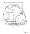
- the body tuning system 1400is particularly beneficial in embodiments having irregular contours of the crown 12 , such as the embodiments seen best in FIGS. 1-2 and 23-25 , or a particularly bulbous crown 12 that extends significantly above the top edge of the face 18 , as seen in FIG. 8 .
- the body tuning element 1500includes a body tuning element toe end 1510 , a body tuning element heel end 1520 , a body tuning element length 1530 , a body tuning element height 1540 , and a body tuning element width 1550 , seen best in FIGS. 9-10, 19, 23, and 31 .
- an embodiment of the body tuning element 1500has a body tuning element sole portion 1570 in contact with the sole 14 and extending in a substantially heel-to-toe direction.
- the body tuning element 1500is separated from the channel 212 by a body tuning separation distance 1560 , seen in FIG. 10 , which is greater than the maximum channel width Wg.
- the body tuning element length 1530is measured in a straight line along the ground plane from a vertical projection of the body tuning element toe end 1510 on the ground plane to a vertical projection of the body tuning element heel end 1520 on the ground plane.
- the body tuning separation distance 1560is measured in a straight line along the ground plane from a vertical projection of a location on the body tuning element 1500 to the nearest vertical projection of the channel 212 onto the ground plane.
- the body tuning separation distance 1560is greater than the maximum channel width Wg throughout at least 50% of the body tuning element length 1530 ; whereas in another embodiment the body tuning separation distance 1560 is at least twice the maximum channel width Wg throughout at least 50% of the body tuning element length 1530 ; in yet a further embodiment the body tuning separation distance 1560 is 150-300% of the maximum channel width Wg throughout at least 50% of the body tuning element length 1530 ; and in a further embodiment the body tuning separation distance 1560 is 175-250% of the maximum channel width Wg throughout at least 50% of the body tuning element length 1530
- Beneficial tuningis achieved in a further embodiment without adding undue rigidity to the club head 2 and limiting beneficial flexing of the club head 2 when at least a portion of the body tuning element height 1540 is at least 15% of the maximum channel depth Dg, and in a further embodiment at least a portion of the body tuning element height 1540 is no more than 75% of the maximum channel depth Dg, while in an even further embodiment at least a portion of the body tuning element height 1540 is 25-50% of the maximum channel depth Dg.
- a body tuning element length 1530as seen in FIG. 19 , of at least 50% of the channel length Lg, while in another embodiment the body tuning element length 1530 is at least 75% of the channel length Lg.
- a longitudinal channel tuning element 1200link the body tuning element length 1530 to the longitudinal tuning element length 1230 such that in one embodiment the body tuning element length 1530 is at least 50% of the longitudinal tuning element length 1230 , while in a further embodiment the body tuning element length 1530 is at least 75% of the longitudinal tuning element length 1230 .
- any of the described relationships of the body tuning element 1500 with respect to percentages of the body tuning element length 1530may also be applied throughout the indicated percentages of the longitudinal tuning element length 1230 and/or the channel length Lg to achieve the desired tuning and avoidance of undue club head 2 rigidity.
- the body tuning system 1400is particularly beneficial in embodiments having irregular contours of the crown 12 , such as the embodiments seen best in FIGS. 1-2 and 23-25 , and embodiments having a bulbous crown with an apex that is significantly above a top edge of the face 18 , therefore some embodiments may have a body tuning system 1500 that further includes a body tuning element crown portion 1580 in contact with the crown 12 , as seen in FIG. 23 .
- One such embodimenthas a body tuning element crown portion 1580 in contact with the crown 12 throughout at least 50% of the longitudinal tuning element length 1230 and/or at least 50% of the channel length Lg; while a further embodiment has the body tuning element crown portion 1580 in contact with the crown 12 throughout at least 75% of the longitudinal tuning element length 1230 and/or at least 75% of the channel length Lg.
- One particular embodimenthas at least a portion of the body tuning element crown portion 1580 connected to the body tuning element sole portion 1570 , while in an even further embodiment the body tuning element crown portion 1580 is connected to the body tuning element sole portion 1570 at both the heel portion 26 and the toe portion 28 , as seen in FIG. 23 .
- One embodiment having irregular crown contourshas a body tuning element crown portion 1580 with at least one section that is concave downward toward the sole 14 and at least one section that is concave upward toward the crown 12
- the embodiment of FIG. 23includes one section that is concave downward toward the sole 14 and two sections that are concave upward toward the crown 12 separated by the concave downward section.
- the concave downward sectionis integrally formed with at least one concave upward section.
- the crown 12may be a crown insert attached to the club head 2 , and in such embodiments the crown insert may be constructed of a different, generally lighter, material, which may further contribute to the need for a channel tuning system 1100 and/or a body tuning system 1400 .
- portions of the body tuning system 1400are in contact with the sole 14 and/or crown 12 , which in one embodiment means that they are integrally cast with the sole 14 and/or crown 12 , while in another embodiment they are attached to the sole 14 and/or crown 12 via available joining methods including welding, brazing, and adhesive attachment.
- the body tuning element 1500is preferably oriented in a direction that is plus, or minus, 45 degrees from a vertical heel-to-toe plane parallel to a vertical heel-to-toe plane containing the centerline axis 21 , however in a further embodiment the body tuning element 1500 is preferably oriented in a direction that is plus, or minus, 20 degrees from a vertical heel-to-toe plane parallel to a vertical heel-to-toe plane containing the centerline axis 21 , and in an even further embodiment the body tuning element 1500 is preferably oriented in a direction that is substantially parallel to a vertical heel-to-toe plane containing the centerline axis 21 .
- the body tuning element 1500may traverse a portion of the club head 2 a linear fashion, a zig-zag or sawtooth type fashion, or a curved fashion.
- Another embodimentincorporates the aerodynamic benefits of a uniquely shaped crown 12 as disclosed in U.S. patent application Ser. Nos. 14/260,328, 14/330,205, 14/259,475, and 14/88,354, all of which are incorporated by reference in their entirety herein.
- One such embodimenthas a club head depth Dch, seen in FIG. 7 , that is at least 4.4 inches, while in a further embodiment the club head depth Dch is at least 4.5 inches, and at least 4.6 inches in yet a further embodiment.
- Aerodynamic characteristicsare particularly beneficial in embodiments having a maximum top edge elevation, Hte, of at least 2.0 inches, while in a further embodiment the maximum top edge elevation, Hte, is at least 2.2 inches, and at least 2.4 inches in yet a further embodiment.
- the highest point on the crown 12establishes the club head height, Hch, above the ground plane, as seen in FIGS. 8 and 10 , and this highest point on the crown 12 is referred to as the crown apex.
- An apex ratiois the ratio of club head height, Hch, to the maximum top edge elevation, Hte. In one embodiment the apex ratio is at least 1.13, thereby encouraging airflow reattachment and reduced aerodynamic drag, while the apex ratio is at least 1.15 in a further embodiment, at least 1.17 in an even further embodiment, and at least 1.19 in yet another embodiment.
- One manner of controlling the height of the CGis to incorporate a crown structure such as that disclosed in U.S. patent application Ser. No. 14/734,181, which is incorporated by reference in its entirety herein. Therefore, in one embodiment majority of the crown 12 has a thickness of 0.7 mm or less, while in a further embodiment majority of the crown 12 has a thickness of 0.65 mm or less.
- At least a portion of the crown 12has a thickness of 0.5 mm or less, while in yet a further embodiment at least a portion of the crown 12 has a thickness of 0.4 mm or less; in another embodiment such crown 12 embodiments having thin portions may also have a portion with a thickness of at least 0.7 mm.
- the crown 12may have a front crown portion 901 , as seen in FIG. 9 , with a relatively greater thickness than a back crown portion 905 in order to provide greater durability to the golf club head 2 .
- the front crown portion 901has a thickness of from about 0.6 to about 1.0 mm, such as from about 0.7 to about 0.9 mm, or about 0.8 mm.
- at least a portion of the back crown portion 905has a thickness that is less than 60% of the front crown portion 901 .
- majority of this portion of the crown 12has a thickness of 0.7 mm or less, while in a further embodiment majority of this portion of the crown 12 has a thickness of 0.6 mm or less, while in yet another embodiment majority of this portion of the crown 12 has a thickness of 0.5 mm or less.
- the foregoing thicknessesrefer to the components of the golf club head 2 after all manufacturing steps have been taken, including construction (e.g., casting, stamping, welding, brazing, etc.), finishing (e.g., polishing, etc.), and any other steps.
- Another manner of controlling the height of the CG, while still incorporating an aerodynamically bulbous crownis to incorporate at least one recessed area into the crown, as seen in FIGS. 1 and 2 , in lieu of a traditional crown 12 of relatively consistent curvature.
- Such bulbous crown embodiments, and the associated thin-crown embodiments and recessed area crown embodiments,are designed to reduce the impact of the bulbous crown on the CG location, often introduce new less desirable characteristics to the club head 2 , similar to those discussed with the introduction of the channel 212 .
- a body tuning system 1400may reduce the less desirable characteristics. For instance, one embodiment incorporates a body tuning element crown portion 1580 that is partially above the maximum top edge elevation, Hte, of the face 18 , as seen in FIG.
- a further embodimenthas at least a portion of the body tuning element crown portion 1580 at an elevation that is at least 5% greater than the maximum top edge elevation, Hte, of the face 18
- yet another embodimenthas at least a portion of the body tuning element crown portion 1580 at an elevation that is at least 10% greater than the maximum top edge elevation, Hte, of the face 18
- Another embodimentincorporates a body tuning element crown portion 1580 that extends continuously across the portion of the crown 12 that is located at an elevation above the maximum face top edge elevation, Hte, of the face 18 .
- Such embodimentsalong with the previously disclosed embodiments disclosing relationships of the body tuning separation distance 1560 to other club head 2 variables, effectively establish the portion of the crown 12 that lies above the maximum face top edge elevation, Hte, of the face 18 .
- the body tuning system 1400further includes a body tuning element connecting element 1600 having a connecting element sole end 1610 engaging the body tuning element sole portion 1570 , and a connecting element crown end 1620 engaging the body tuning element crown portion 1580 , as seen in FIG. 23 .
- the body tuning element connecting element 1600or a portion of it, may be integrally cast with the body tuning element sole portion 1570 and/or the body tuning element crown portion 1580 , while in another embodiment the attachment may be made via available joining methods including welding, brazing, and adhesive attachment, or mechanically attached such as in an embodiment like FIG. 26 having a crown insert.
- the body tuning element connecting element 1600may be a single piece connected to either the body tuning element sole portion 1570 and/or the body tuning element crown portion 1580 that then engages the other portion when the crown insert is installed, or the body tuning element connecting element 1600 may be composed of multiple sections that then engages the other section when the crown insert is installed.
- the body tuning element sole portion 1570 and/or the body tuning element crown portion 1580may be formed to include a receiver to cooperate and receive an end of the body tuning element connecting element 1600 .
- the body tuning element connecting element 1600effectively joins the crown 12 and sole 14 to further tune the club head 2 and reduce undesirable vibrations.
- the location of the body tuning element connecting element 1600is largely dictated by the location of the body tuning element sole portion 1570 and the body tuning element crown portion 1580 , and therefore all the relationships disclosed regarding their location with respect to the channel 212 also apply to the location of the body tuning element connecting element 1600 . Further, one particular embodiment provides preferred performance when the body tuning element connecting element 1600 is located on the toe side of the club head 2 , or between the ideal impact location 23 and the toe 28 . In another embodiment the body tuning element connecting element 1600 is located on the toe side of the club head 2 and in the rear half of the club head 2 , using the club head depth Dch seen in FIG. 7 to determine the rear half. Still further, in another embodiment the connecting element crown end 1620 engages the body tuning element crown portion 1580 at an elevation below the maximum face top edge elevation, Hte, of the face 18 .
- the orientation and construction of the body tuning element connecting element 1600influences the benefits associated with it.
- the body tuning element connecting element 1600is oriented at an angle that is plus, or minus, 10 degrees from vertical; while in a further embodiment the orientation is plus, or minus, 5 degrees from vertical; and in an even further embodiment the orientation is substantially vertical.
- the cross-sectional shape of the body tuning element connecting element 1600 in a plane perpendicular to a longitudinal axis of the body tuning element connecting element 1600is round in one embodiment.
- the body tuning element connecting element 1600is solid, while in an alternative embodiment the body tuning element connecting element 1600 is hollow.
- the minimum cross-sectional dimension of the body tuning element connecting element 1600is at least as great as the minimum body tuning element width 1550 , while in a further embodiment it is at least as great as the maximum body tuning element width 1500 , while in yet another embodiment it is at least twice the maximum body tuning element width 1500 , and in still a further embodiment it is 2-5 times the maximum body tuning element width 1500 .
- the minimum wall thickness of the body tuning element connecting element 1600is at least as great as the minimum body tuning element width 1550 .
- a further embodimentincludes a bridge 1700 , seen in FIG. 23 , connecting the body tuning element 1500 with the sole engaging channel tuning element 1300 , and in one embodiment the bridge 1700 engages the body tuning element 1500 at the connecting element sole end 1610 .
- the benefits of the channel tuning system 1100 and/or body tuning system 1400are heightened as the size of the channel 212 increases.
- the disclosed embodimentsare used in conjunction with a channel 212 having a volume that is at least 3% of the club head 2 volume, while in a further embodiment the channel 212 has a volume that is 4-10% of the club head 2 volume, and in an even further embodiment the channel 212 has a volume that is at least 5% of the club head 2 volume.
- the channel 212has a volume that is at least 15 cubic centimeters (cc), while a further embodiment has a channel 212 volume that is 15-40 cc, and an even further embodiment has a channel 212 volume of at least 20 cc.
- One skilled in the artwill know how to determine such volumes by submerging at least a portion of the club head in a liquid, and then doing the same with the channel 212 covered, or by filling the channel 212 with clay or other malleable material to achieve a smooth exterior profile of the club head and then removing and measuring the volume of the malleable material.
- the benefits of the channel tuning system 1100 and/or body tuning system 1400are heightened as the channel width Wg, channel depth Dg, and/or channel length Lg increase.
- beneficial flexing of the club head 2 , and reduced stress in the channel 212may be achieved as the size of the channel 212 increases, however there is a point at which the negatives outweigh the positives, yet the channel tuning system 1100 and/or body tuning system 1400 , as well as the upper channel wall radius of curvature 222 R, beneficially shift, or control, when the negatives outweigh the positives.
- any of the disclosed embodimentsare used in conjunction with a channel 212 that has a portion with a channel depth Dg that is at least 20% of the Zup value, while a further embodiment has a portion with the channel depth Dg being at least 30% of the Zup value, and an even further embodiment has a portion with the channel depth Dg being 30-70% of the Zup value.
- any of the disclosed embodimentsare used in conjunction with a channel 212 that has a portion with a channel depth Dg that is at least 8 mm, while a further embodiment has a portion with the channel depth Dg being at least 10 mm, while an even further embodiment has a portion with the channel depth Dg being at least 12 mm, and yet another embodiment has a portion with the channel depth Dg being 10-15 mm.
- One embodimenthas a Zup value that is less than 30 mm.
- the length Lg of the channel 212may be defined relative to the width of the striking face Wss. For example, in some embodiments, the length Lg of the channel 212 is from about 70% to about 140%, or about 80% to about 140%, or about 100% of the width of the striking face Wss.
- the configuration of the crown 12including the shape, and in some embodiments the amount of the bulbous crown 12 at an elevation above the maximum face top edge elevation, Hte, of the face 18 , as well as the crown thickness, influence the overall rigidity, or alternatively the flexibility, of the club head 2 , which must compliment the benefits associated with the channel 212 , and vice versa, rather than fight the benefits associated with the channel 212 and/or crown thickness, and in some embodiments the relationships further serve to achieve the desired tuning characteristics of the club head 2 .
- the difference between the maximum club head height, Hch, or apex height, and the maximum face top edge elevation, Hte, of the face 18is at least 50% of the maximum channel depth, Dg, while in a further embodiment the difference is at least 70% of the maximum channel depth, Dg, in yet another embodiment the difference is 70-125% of the maximum channel depth, Dg, and in still a further embodiment the difference is 80-110% of the maximum channel depth, Dg.
- the difference between the maximum club head height, Hch, or apex height, and the maximum face top edge elevation, Hte, of the face 18is at least 25% of the maximum channel width, Wg, while in a further embodiment the difference is at least 50% of the maximum channel width, Wg, in yet another embodiment the difference is 60-120% of the maximum channel width, Wg, and in still a further embodiment the difference is 70-110% of the maximum channel width, Wg.
- a further bulbous crown embodimenthas an apex ratio of at least 1.13 and the maximum channel depth, Dg, is at least 10% of the difference between the maximum club head height, Hch, or apex height, and the maximum face top edge elevation, Hte, of the face 18 ; while in a further embodiment the apex ratio is at least 1.15 and the maximum channel depth, Dg, is at least 20% of the difference between the maximum club head height, Hch, or apex height, and the maximum face top edge elevation, Hte, of the face 18 ; and in yet another embodiment the apex ratio is at least 1.15 and the maximum channel depth, Dg, is 60-120% of the difference between the maximum club head height, Hch, or apex height, and the maximum face top edge elevation, Hte, of the face 18 .
- a majority of the portion of the crown 12 located at an elevation above the maximum face top edge elevation, Htehas a crown thickness of 0.7 mm or less; while in another embodiment majority of the portion of the crown 12 located at an elevation above the maximum face top edge elevation, Hte, has a crown thickness that is less than a maximum channel wall thickness 221 ; and in yet an even further embodiment majority of the portion of the crown 12 located at an elevation above the maximum face top edge elevation, Hte, has a crown thickness that is less than a minimum channel wall thickness 221 . In another embodiment majority of the portion of the crown 12 located at an elevation above the maximum face top edge elevation, Hte, has a crown thickness that is 25-75% of a minimum channel wall thickness 221 .
- any of the disclosed embodimentsare used in conjunction with a channel 212 that has a portion with a channel width Wg that is at least 20% of the Zup value, while a further embodiment has a portion with the channel width Wg being at least 30% of the Zup value, and an even further embodiment has a portion with the channel width Wg being 25-60% of the Zup value.
- the Zup valueis 20-36 mm, while in a further embodiment the Zup value is 24-32 mm, while in an even further embodiment the Zup value is 26-30 mm.
- the Zup valueis 8-20 mm, while in a further embodiment the Zup value is 10-18 mm, while in an even further embodiment the Zup value is 12-16 mm.
- Another embodimentfurther improves the stress distribution in the channel 212 when any of the disclosed embodiments are used in conjunction with a channel 212 that has a portion with an upper channel wall radius of curvature 222 R, seen in FIG. 9 , that is at least 20% of the maximum channel width Wg, while a further embodiment has a portion with an upper channel wall radius of curvature 222 R that is at least 25% of the maximum channel width Wg, and an even further embodiment has a portion with an upper channel wall radius of curvature 222 R that is at least 30% of the maximum channel width Wg.
- any of the disclosed embodimentsare used in conjunction with a channel 212 that has a channel length Lg that is at least 50% of the face width Wss, while in another embodiment any of the disclosed embodiments are used in conjunction with a channel 212 that has a channel length Lg that is at least 75% of the face width Wss, and in an even further embodiment any of the disclosed embodiments are used in conjunction with a channel 212 that has a channel length Lg that is greater than the face width Wss.
- the channel 212may further include an aperture as disclosed in U.S. patent application Ser. No. 14/472,415, which is incorporated herein by reference.
- the crown 12may include a post apex attachment promoting region as disclosed in U.S. patent application Ser. No. 14/259,475, which is incorporated herein by reference, a drop contour area as disclosed in U.S. patent application Ser. No. 14/488,354, which is incorporated herein by reference, a trip step as disclosed in U.S. patent application Ser. No. 14/330,205, which is incorporated herein by reference, and/or unique crown curvature as disclosed in U.S. patent application Ser. No. 14/260,328, which is incorporated herein by reference
- channel central region 225is the portion of the channel 212 within 1 ⁇ 2 inch on either side of the ideal impact location 23 , and within the channel central region 225 a portion of the channel 212 has a wall thickness 221 that is at least twice the thinnest portion of the channel 212 located outside of the channel central region 225 , while in a further embodiment the wall thickness 221 through the entire channel central region 225 is at least twice the thinnest portion of the channel 212 located outside of the channel central region 225 .
- a portion of the channel 212 within the channel central region 225has a wall thickness 221 that is at least 2.0 mm, and a portion of the channel 212 located outside of the channel central region 225 has a wall thickness 221 that is 1.0 mm or less, while in another embodiment the channel central region 225 has a wall thickness 221 that is at least 2.5 mm, and in yet another embodiment no portion of the channel central region 225 has a wall thickness 221 greater than 3.5 mm.
- the portion of the sole 14 in front of the channel central region 225has a sole thickness that is at least as thick as the maximum channel wall thickness 221 in the channel central region 225 , while in an even further embodiment the portion of the sole 14 in front of the channel central region 225 has a sole thickness that is at least twice the thinnest portion of the channel 212 located outside of the channel central region 225 , while in another embodiment the portion of the sole 14 in front of the channel central region 225 has a sole thickness that is at least 2.0 mm, and in yet another embodiment the entire portion of the sole 14 in front of the channel central region 225 has a sole thickness that is 2.5-3.5 mm.
- the embodiments of this paragraphalso stabilize the face 18 , lower the peak stress in the channel 212 , and reduce the spin imparted on a golf ball at impact.
- the rear channel wall 218 and front channel wall 220define a channel angle ⁇ therebetween.
- the channel angle ⁇can be between about 10° to about 30°, such as about 13° to about 28°, or about 13° to about 22°.
- the rear channel wall 218extends substantially perpendicular to the ground plane when the club head 2 is in the normal address position, i.e., substantially parallel to the z-axis 65 .
- the front channel wall 220defines a surface that is substantially parallel to the striking face 18 , i.e., the front channel wall 220 is inclined relative to a vector normal to the ground plane (when the club head 2 is in the normal address position) by an angle that is within about ⁇ 5° of the loft angle 15 , such as within about ⁇ 3° of the loft angle 15 , or within about ⁇ 1° of the loft angle 15 .
- the heel channel wall 214 , toe channel wall 216 , rear channel wall 218 , and front channel wall 220each have a thickness 221 of from about 0.7 mm to about 1.5 mm, e.g., from about 0.8 mm to about 1.3 mm, or from about 0.9 mm to about 1.1 mm.
- a weight port 40may be located on the sole portion 14 of the golf club head 2 , and is located adjacent to and rearward of the channel 212 .
- the weight port 40is located on the sole portion 14 of the golf club head 2 , and is located adjacent to and rearward of the body tuning system 1500 .
- Still a further embodimenthas at least one weight port 40 is located on the sole portion 14 of the golf club head 2 , and located adjacent to and between the channel 212 and the body tuning system 1500 ; while an even further embodiment has at least two weight ports 40 is located on the sole portion 14 of the golf club head 2 , and located adjacent to and between the channel 212 and the body tuning system 1500 .
- the deformationis localized in the area of the channel 212 , since the club head 2 is much stiffer in the area of the at least one weight port 40 .
- the ball speed after impactis greater for the club head having the channel 212 and at least one weight port 40 than for a conventional club head, which results in a higher COR.
- the weight port 40may be located adjacent to and rearward of the rear channel wall 218 .
- One or more mass padsmay also be located in a forward position on the sole 14 of the golf club head 2 , contiguous with both the rear channel wall 218 and the weight port 40 .
- the configuration of the channel 212 and its position near the face 18allows the face plate to undergo more deformation while striking a ball than a comparable club head without the channel 212 , thereby increasing both COR and the speed of golf balls struck by the golf club head.
- the weight port 40or ports, are located adjacent to and rearward of the rear channel wall 218 .
- the weight ports 40are separated from the rear channel wall 218 by a distance of approximately 1 mm to about 10 mm, such as about 1.5 mm to about 8 mm.
- the configuration of the channel 212 and its position near the face 18allows the face plate to undergo more deformation while striking a ball than a comparable club head without the channel 212 , thereby increasing both COR and the speed of golf balls struck by the golf club head.
- the ball speed after impactis greater for the club head having the channel 212 than for a conventional club head, which results in a higher COR.
- the slot 212has a substantially constant width Wg, and the slot 212 is defined by a radius of curvature for each of the forward edge and rearward edge of the slot 212 .
- the radius of curvature of the forward edge of the slot 212is substantially the same as the radius of curvature of the forward edge of the sole 14 .
- the radius of curvature of each of the forward and rearward edges of the slot 212is from about 15 mm to about 90 mm, such as from about 20 mm to about 70 mm, such as from about 30 mm to about 60 mm.
- the slot width Wgchanges at different locations along the length of the slot 212 .
- a club shaftis received within the hosel bore 24 and is aligned with the centerline axis 21 .
- a connection assemblyis provided that allows the shaft to be easily disconnected from the club head 2 .
- the connection assemblyprovides the ability for the user to selectively adjust the loft-angle 15 and/or lie-angle 19 of the golf club.
- a sleeveis mounted on a lower end portion of the shaft and is configured to be inserted into the hosel bore 24 .
- the sleevehas an upper portion defining an upper opening that receives the lower end portion of the shaft, and a lower portion having a plurality of longitudinally extending, angularly spaced external splines located below the shaft and adapted to mate with complimentary splines in the hosel opening 24 .
- the lower portion of the sleevedefines a longitudinally extending, internally threaded opening adapted to receive a screw for securing the shaft assembly to the club head 2 when the sleeve is inserted into the hosel opening 24 .
- FIG. 34shows an embodiment of a golf club assembly that includes a club head 3050 having a hosel 3052 defining a hosel opening 3054 , which in turn is adapted to receive a hosel insert 2000 .
- the hosel opening 3054is also adapted to receive a shaft sleeve 3056 mounted on the lower end portion of a shaft (not shown in FIG. 28 ) as described in U.S. patent application Ser. No. 14/074,481.
- the hosel opening 3054extends from the hosel 3052 through the club head and opens at the sole, or bottom surface, of the club head.
- the club headis removably attached to the shaft by the sleeve 3056 (which is mounted to the lower end portion of the shaft) by inserting the sleeve 3056 into the hosel opening 3054 and the hosel insert 2000 (which is mounted inside the hosel opening 3054 ), and inserting a screw 4000 upwardly through an opening in the sole and tightening the screw into a threaded opening of the sleeve, thereby securing the club head to the sleeve 3056 .
- the shaft sleeve 3056has a lower portion 3058 including splines that mate with mating splines of the hosel insert 2000 , an intermediate portion 3060 and an upper head portion 3062 .
- the intermediate portion 3060 and the head portion 3062define an internal bore 3064 for receiving the tip end portion of the shaft.
- the intermediate portion 3060 of the shaft sleevehas a cylindrical external surface that is concentric with the inner cylindrical surface of the hosel opening 3054 . In this manner, the lower and intermediate portions 3058 , 3060 of the shaft sleeve and the hosel opening 3054 define a longitudinal axis B.
- the bore 3064 in the shaft sleevedefines a longitudinal axis A to support the shaft along axis A, which is offset from axis B by a predetermined angle 3066 determined by the bore 3064 .
- inserting the shaft sleeve 3056 at different angular positions relative to the hosel insert 2000is effective to adjust the shaft loft and/or the lie angle.
- FIGS. 35 and 36are enlarged views of the shaft sleeve 3056 .
- the head portion 3062 of the shaft sleeve(which extends above the hosel 3052 ) can be angled relative to the intermediate portion 3060 by the angle 3066 so that the shaft and the head portion 3062 are both aligned along axis A.
- the head portion 3062can be aligned along axis B so that it is parallel to the intermediate portion 3060 and the lower portion 3058 .
- FIGS. 37 and 38A -Eshow an embodiment of a golf club head 2 having a shaft connection assembly that allows the shaft to be easily disconnected from the club head 2 , and that provides the ability for the user to selectively adjust the loft-angle 15 and/or lie-angle 19 of the golf club.
- the club head 2includes a hosel 20 defining a hosel bore 24 , which in turn is adapted to receive a hosel insert 2000 .
- the hosel bore 24is also adapted to receive a shaft sleeve 3056 mounted on the lower end portion of a shaft (not shown in FIGS. 34 and 38A -F) as described in U.S. patent application Ser. No. 14/074,481.
- a recessed port 3070is provided on the sole, and extends from the bottom portion of the golf club head into the interior of the body 10 toward the crown portion 12 .
- the hosel bore 24extends from the hosel 20 through the club head 2 and opens within the recessed portion 3070 at the sole of the club head.
- the club head 2is removably attached to the shaft by the sleeve 3056 (which is mounted to the lower end portion of the shaft) by inserting the sleeve 3056 into the hosel bore 24 and the hosel insert 2000 (which is mounted inside the hosel bore 24 ), and inserting a screw 4000 upwardly through the recessed port 3070 and through an opening in the sole and tightening the screw into a threaded opening of the sleeve, thereby securing the club head to the sleeve 3056 .
- a screw capturing devicesuch as in the form of an o-ring or washer 3036 , can be placed on the shaft of the screw 4000 to retain the screw in place within the club head when the screw is loosened to permit removal of the shaft from the club head.
- the recessed port 3070extends from the bottom portion of the golf club head into the interior of the outer shell toward the top portion of the club head ( 400 ), as seen in FIGS. 37 and 38A -E.
- the mouth of the recessed port 3070is generally rectangular, although the shape and size of the recessed port 3070 may be different in alternative embodiments.
- the recessed port 3070is defined by a port toe wall 3072 , a port fore-wall 3074 , and/or a port aft-wall 3076 , as seen in FIG. 37 .
- a portion of the recessed port 3070connects to the channel 212 at an interface referred to as a port-to-channel junction 3080 , seen best in the sections FIGS.
- the portion of the channel 212 located near the heel portion of the club head 2does not have a distinct rear wall at the port-to-channel junction 3080 and the port fore-wall 3074 supports a portion of the channel 212 located near the heel and serves to stabilize the heel portion of the channel 212 while permitting deflection of the channel 212 .
- the port-to-channel junction 3080may be along the port aft-wall 3076 or the port toe wall 3072 .
- Such embodimentsallow the recessed port 3070 and the channel 212 to coexist in a relatively tight area on the club head while providing a stable connection and preferential deformation of the portion of the channel 212 located toward the heel of the club head.
- the channel 212extends over a portion of the sole 14 of the golf club head 2 in the forward portion of the sole 14 adjacent to or near the striking face 18 .
- the channel 212extends into the interior of the club head body 10 and may have an inverted “V” shape, a length Lg, a width Wg, and a depth Dg as discussed above.
- the channel 212may merge with the recessed port 3070 at the port-to-channel junction 3080 .
- the channel width Wgis from about 3.5 mm to about 8.0 mm, such as from about 4.5 mm to about 7.0 mm, such as about 6.5 mm.
- a pair of distance measurements L 1 and L 2are also shown in FIG. 38B , with L 1 representing a distance from the toe channel wall 216 to a point within the channel corresponding with the port-to-channel junction 3080 , and with L 2 representing a distance from a point representing an intersection of the upper channel wall 222 and the toe channel wall 216 to a point on the upper channel wall 222 adjacent to the bore for the screw 4000 .
- the L 1 distanceis about 58 mm and the L 2 distance is about 63 mm.
- the port width Wp and port length Lpare measurements for the port width Wp and port length Lp, which define the generally rectangular shape of the recessed port 3070 in the illustrated embodiment.
- the port width Wpis measured from a midpoint of the mouth of the port fore-wall 3074 to a midpoint of the mouth of the port aft-wall 3076 .
- the port length Lpis measured from a midpoint of the heel edge of the recessed port 3070 to a midpoint of the mouth of the port toe wall 3072 .
- the port width Wpis from about 8 mm to about 25 mm, such as from about 10 mm to about 20 mm, such as about 15.5 mm.
- the port length Lpis from about 12 mm to about 30 mm, such as from about 15 mm to about 25 mm, such as about 20 mm.
- the recessed portion 3070has a shape that is other than rectangular, such as round, triangular, square, or some other regular geometric or irregular shape.
- a port width Wpmay be measured from the port fore-wall 3074 to a rearward-most point of the recessed port.
- the port width W.sub.pmay be measured from the port fore-wall 3074 to a rearward-most point located on the rounded aft-wall.
- a ratio Wp/Wg of the port width Wp to an average width of the channel Wgmay be from about 1.1 to about 20, such as about 1.2 to about 15, such as about 1.5 to about 10, such as about 2 to about 8.
- FIGS. 38C-Ethe transition from the area and volume comprising the recessed port 3070 to the area and volume comprising the channel 212 is illustrated.
- the hosel opening 3054is shown in communication with the recessed port 3070 via a passage 3055 through which the screw 400 of the shaft attachment system is able to pass.
- a bottom wall 3078 of the recessed port 3070forms a transition between the port fore-wall 3074 and the port aft-wall 3076 .
- the port-to-channel junction 3080defines the transition from the recessed port 3070 to the channel 212 .
- a weight port 40is located on the sole portion 14 of the golf club head 2 , and is located adjacent to and rearward of the channel 212 .
- the weight port 40can have any of a number of various configurations to receive and retain any of a number of weights or weight assemblies, such as described in U.S. Pat. Nos. 7,407,447 and 7,419,441, which are incorporated herein by reference.
- the weight port 40is located adjacent to and rearward of the rear channel wall 218 .
- One or more mass padsmay also be located in a forward position on the sole 14 of the golf club head 2 , contiguous with both the rear channel wall 218 and the weight port 40 .
- the configuration of the channel 212 and its position near the face 18allows the face 18 to undergo more deformation while striking a ball than a comparable club head without the channel 212 , thereby increasing both COR and the speed of golf balls struck by the golf club head.
- the mass pad rearward of the channel 212By positioning the mass pad rearward of the channel 212 , the deformation is localized in the area of the channel 212 , since the club head is much stiffer in the area of the mass pad. As a result, the ball speed after impact is greater for the club head having the channel 212 and mass pad than for a conventional club head, which results in a higher COR.
Landscapes
- Health & Medical Sciences (AREA)
- General Health & Medical Sciences (AREA)
- Physical Education & Sports Medicine (AREA)
- Life Sciences & Earth Sciences (AREA)
- Engineering & Computer Science (AREA)
- Wood Science & Technology (AREA)
- Golf Clubs (AREA)
Abstract
Description
Izz=∫(x2+y2)dm
where x is the distance from a golf club head CG yz-plane to an infinitesimal mass, dm, and y is the distance from the golf club head CG xz-plane to the infinitesimal mass, dm. The golf club head CG yz-plane is a plane defined by the golf club head CG y-
Ixx=∫(y2+z2)dm
where y is the distance from a golf club head CG xz-plane to an infinitesimal mass, dm, and z is the distance from a golf club head CG xy-plane to the infinitesimal mass, dm. The golf club head CG xz-plane is a plane defined by the golf club head CG x-axis90 and the golf club head CG z-
Izz≥13·Zup+105.
Ixx+Izz≥20·Zup+165.
Ixx≥7·Zup+60.
Coefficient of Restitution, Characteristic Time, and Center of Gravity Projection
| TABLE 1 | ||||
| Elements of the | Mode 1 | |||
| Channel Tuning | Mode 1 | Drop | Drop | |
| System (1100) Present | (Hz) | (Hz) | (Hz) | (Hz) |
| 1200 + 1300 + 1380 + 1390 | 3530 | 3729 | ||
| 1200 + 1300 + 1380 | 3328 | 3727 | 202 | 2 |
| 1200 + 1380 + 1390 | 3322 | 3694 | 208 | 35 |
| 1200 + 1300 + 1390 | 3377 | 3726 | 153 | 3 |
| 1300 + 1380 + 1390 | 3503 | 3728 | 27 | 1 |
Claims (22)
Priority Applications (5)
| Application Number | Priority Date | Filing Date | Title |
|---|---|---|---|
| US15/645,587US10434384B2 (en) | 2010-12-28 | 2017-07-10 | Golf club head |
| US16/579,666US10905929B2 (en) | 2010-12-28 | 2019-09-23 | Golf club head |
| US17/146,097US11298599B2 (en) | 2010-12-28 | 2021-01-11 | Golf club head |
| US17/686,181US11850484B2 (en) | 2010-12-28 | 2022-03-03 | Golf club head |
| US18/502,408US20240139592A1 (en) | 2010-12-28 | 2023-11-06 | Golf club head |
Applications Claiming Priority (9)
| Application Number | Priority Date | Filing Date | Title |
|---|---|---|---|
| US201061427772P | 2010-12-28 | 2010-12-28 | |
| US13/338,197US8900069B2 (en) | 2010-12-28 | 2011-12-27 | Fairway wood center of gravity projection |
| US13/469,031US9220953B2 (en) | 2010-12-28 | 2012-05-10 | Fairway wood center of gravity projection |
| US13/828,675US8888607B2 (en) | 2010-12-28 | 2013-03-14 | Fairway wood center of gravity projection |
| US14/495,795US9186560B2 (en) | 2010-12-28 | 2014-09-24 | Golf club |
| US14/701,476US9211447B2 (en) | 2010-12-28 | 2015-04-30 | Golf club |
| US14/871,789US9700763B2 (en) | 2010-12-28 | 2015-09-30 | Golf club |
| US14/939,648US9707457B2 (en) | 2010-12-28 | 2015-11-12 | Golf club |
| US15/645,587US10434384B2 (en) | 2010-12-28 | 2017-07-10 | Golf club head |
Related Parent Applications (1)
| Application Number | Title | Priority Date | Filing Date |
|---|---|---|---|
| US14/939,648ContinuationUS9707457B2 (en) | 2010-12-28 | 2015-11-12 | Golf club |
Related Child Applications (1)
| Application Number | Title | Priority Date | Filing Date |
|---|---|---|---|
| US16/579,666ContinuationUS10905929B2 (en) | 2010-12-28 | 2019-09-23 | Golf club head |
Publications (2)
| Publication Number | Publication Date |
|---|---|
| US20170304693A1 US20170304693A1 (en) | 2017-10-26 |
| US10434384B2true US10434384B2 (en) | 2019-10-08 |
Family
ID=55401349
Family Applications (6)
| Application Number | Title | Priority Date | Filing Date |
|---|---|---|---|
| US14/939,648Expired - Fee RelatedUS9707457B2 (en) | 2010-12-28 | 2015-11-12 | Golf club |
| US15/645,587ActiveUS10434384B2 (en) | 2010-12-28 | 2017-07-10 | Golf club head |
| US16/579,666ActiveUS10905929B2 (en) | 2010-12-28 | 2019-09-23 | Golf club head |
| US17/146,097ActiveUS11298599B2 (en) | 2010-12-28 | 2021-01-11 | Golf club head |
| US17/686,181ActiveUS11850484B2 (en) | 2010-12-28 | 2022-03-03 | Golf club head |
| US18/502,408PendingUS20240139592A1 (en) | 2010-12-28 | 2023-11-06 | Golf club head |
Family Applications Before (1)
| Application Number | Title | Priority Date | Filing Date |
|---|---|---|---|
| US14/939,648Expired - Fee RelatedUS9707457B2 (en) | 2010-12-28 | 2015-11-12 | Golf club |
Family Applications After (4)
| Application Number | Title | Priority Date | Filing Date |
|---|---|---|---|
| US16/579,666ActiveUS10905929B2 (en) | 2010-12-28 | 2019-09-23 | Golf club head |
| US17/146,097ActiveUS11298599B2 (en) | 2010-12-28 | 2021-01-11 | Golf club head |
| US17/686,181ActiveUS11850484B2 (en) | 2010-12-28 | 2022-03-03 | Golf club head |
| US18/502,408PendingUS20240139592A1 (en) | 2010-12-28 | 2023-11-06 | Golf club head |
Country Status (1)
| Country | Link |
|---|---|
| US (6) | US9707457B2 (en) |
Cited By (6)
| Publication number | Priority date | Publication date | Assignee | Title |
|---|---|---|---|---|
| US10569142B2 (en)* | 2016-10-14 | 2020-02-25 | Callaway Golf Company | Golf club head with hosel support structure |
| US20200139210A1 (en)* | 2010-12-28 | 2020-05-07 | Taylor Made Golf Company, Inc. | Golf club head |
| US11618213B1 (en) | 2020-04-17 | 2023-04-04 | Cobra Golf Incorporated | Systems and methods for additive manufacturing of a golf club |
| US11618079B1 (en) | 2020-04-17 | 2023-04-04 | Cobra Golf Incorporated | Systems and methods for additive manufacturing of a golf club |
| US20230285816A1 (en)* | 2010-12-28 | 2023-09-14 | Taylor Made Golf Company, Inc. | Golf club head |
| US12403362B1 (en) | 2020-04-17 | 2025-09-02 | Cobra Golf Incorporated | Systems and methods for additive manufacturing of a golf club |
Families Citing this family (38)
| Publication number | Priority date | Publication date | Assignee | Title |
|---|---|---|---|---|
| US8888607B2 (en) | 2010-12-28 | 2014-11-18 | Taylor Made Golf Company, Inc. | Fairway wood center of gravity projection |
| US10639524B2 (en) | 2010-12-28 | 2020-05-05 | Taylor Made Golf Company, Inc. | Golf club head |
| US9403069B2 (en)* | 2012-05-31 | 2016-08-02 | Nike, Inc. | Golf club head or other ball striking device having impact-influencing body features |
| US9908016B2 (en)* | 2012-06-27 | 2018-03-06 | Callaway Golf Company | Golf club head having optimized ball speed to CT relationship |
| US9750991B2 (en)* | 2013-03-07 | 2017-09-05 | Taylor Made Golf Company, Inc. | Golf club head |
| US20160096083A1 (en)* | 2014-06-20 | 2016-04-07 | Nike, Inc | Golf club head or other ball striking device having impact-influencing body features |
| US10245474B2 (en) | 2014-06-20 | 2019-04-02 | Karsten Manufacturing Corporation | Golf club head or other ball striking device having impact-influencing body features |
| US10751584B2 (en) | 2014-06-20 | 2020-08-25 | Karsten Manufacturing Corporation | Golf club head or other ball striking device having impact-influencing body features |
| US10357694B2 (en)* | 2014-06-20 | 2019-07-23 | Karsten Manufacturing Corporation | Golf club head or other ball striking device having impact-influencing body features |
| US10799772B2 (en)* | 2014-06-20 | 2020-10-13 | Karsten Manufacturing Corporation | Golf club head or other ball striking device having impact-influencing body features |
| US20160067561A1 (en)* | 2014-09-05 | 2016-03-10 | Acushnet Company | Golf club head |
| US11130025B2 (en)* | 2014-10-24 | 2021-09-28 | Karsten Manufacturing Corporation | Golf club heads with energy storage features |
| US20160271462A1 (en)* | 2015-03-17 | 2016-09-22 | Dean L. Knuth | Golf club with low and rearward center of gravity |
| JP6309476B2 (en)* | 2015-03-18 | 2018-04-11 | 美津濃株式会社 | Wood type golf club head and wood type golf club |
| US20160346632A1 (en)* | 2015-05-29 | 2016-12-01 | Nike, Inc. | Golf Club Head or Other Ball Striking Device Having Impact-Influencing Body Features |
| US10874914B2 (en) | 2015-08-14 | 2020-12-29 | Taylor Made Golf Company, Inc. | Golf club head |
| US9914028B1 (en) | 2016-09-06 | 2018-03-13 | Acushnet Company | Golf club with movable weight |
| US9975019B2 (en) | 2015-12-22 | 2018-05-22 | Acushnet Company | Golf club with movable weight |
| US10035051B2 (en) | 2015-12-22 | 2018-07-31 | Acushnet Company | Golf club with movable weight |
| JP6766475B2 (en)* | 2016-06-30 | 2020-10-14 | 住友ゴム工業株式会社 | Hollow golf club head |
| US10195497B1 (en) | 2016-09-13 | 2019-02-05 | Taylor Made Golf Company, Inc | Oversized golf club head and golf club |
| US11618306B2 (en) | 2016-10-27 | 2023-04-04 | Nicholas J. Singer | Skeleton for truck bed and convertible top |
| US10188916B2 (en) | 2017-06-05 | 2019-01-29 | Taylor Made Golf Company, Inc. | Golf club head |
| US10532254B1 (en) | 2017-11-07 | 2020-01-14 | Cobra Golf Incorporated | Low drag golf club head with improved mass properties |
| US10589155B2 (en) | 2017-12-28 | 2020-03-17 | Taylor Made Golf Company, Inc. | Golf club head |
| US10188915B1 (en) | 2017-12-28 | 2019-01-29 | Taylor Made Golf Company, Inc. | Golf club head |
| US10695621B2 (en) | 2017-12-28 | 2020-06-30 | Taylor Made Golf Company, Inc. | Golf club head |
| US10653926B2 (en) | 2018-07-23 | 2020-05-19 | Taylor Made Golf Company, Inc. | Golf club heads |
| US10369437B1 (en) | 2018-08-20 | 2019-08-06 | Acushnet Company | Wood-type golf club including center of gravity adjustment |
| JP7150586B2 (en) | 2018-12-12 | 2022-10-11 | ブリヂストンスポーツ株式会社 | golf club head |
| US10850170B1 (en)* | 2019-05-31 | 2020-12-01 | Acushnet Company | Golf club head |
| USD956540S1 (en) | 2020-02-11 | 2022-07-05 | Nut Shell LLC | Acoustic panel end pair |
| GB2614473A (en)* | 2020-09-10 | 2023-07-05 | Karsten Mfg Corp | Fairway wood golf club head with low CG |
| US11759685B2 (en) | 2020-12-28 | 2023-09-19 | Taylor Made Golf Company, Inc. | Golf club heads |
| US11406881B2 (en) | 2020-12-28 | 2022-08-09 | Taylor Made Golf Company, Inc. | Golf club heads |
| USD1052024S1 (en) | 2022-09-23 | 2024-11-19 | Taylor Made Golf Company, Inc. | Golf club head |
| USD1052025S1 (en) | 2022-09-23 | 2024-11-19 | Taylor Made Golf Company, Inc. | Golf club head |
| USD1057064S1 (en) | 2022-09-23 | 2025-01-07 | Taylor Made Golf Company, Inc. | Golf club head |
Citations (578)
| Publication number | Priority date | Publication date | Assignee | Title |
|---|---|---|---|---|
| US411000A (en) | 1889-09-17 | Euclid anderson | ||
| US1133129A (en) | 1913-03-06 | 1915-03-23 | James Govan | Golf-club. |
| US1135621A (en) | 1914-05-07 | 1915-04-13 | David Roberts | Golf and like club. |
| US1320163A (en) | 1919-10-28 | Oole-cltjb attachment | ||
| GB194823A (en) | 1921-12-23 | 1923-03-22 | James Hamilton Stirling | Improvements in or relating to golf clubs and the like |
| US1518316A (en) | 1922-12-14 | 1924-12-09 | Robert W Ellingham | Golf club |
| US1526438A (en) | 1923-07-16 | 1925-02-17 | Stream Line Company | Golf driver |
| US1538312A (en) | 1925-02-21 | 1925-05-19 | Beat William Neish | Golf club |
| US1592463A (en) | 1926-03-03 | 1926-07-13 | Marker Theodore | Golf club |
| US1658581A (en) | 1927-09-19 | 1928-02-07 | Alexander G Tobia | Metallic golf-club head |
| US1697846A (en) | 1927-05-28 | 1929-01-08 | David W Anderson | Universal golf club |
| US1704119A (en) | 1927-12-09 | 1929-03-05 | R H Buhrke Co | Golf-club construction |
| US1705997A (en) | 1928-09-04 | 1929-03-19 | Quynn John Williams | Golf club |
| US1854548A (en) | 1927-03-08 | 1932-04-19 | James B Hunt | Golf club head |
| US1970409A (en) | 1932-09-27 | 1934-08-14 | Olaf C Wiedemann | Ratchet tool |
| US2214356A (en) | 1938-04-20 | 1940-09-10 | William L Wettlaufer | Testing apparatus for golf clubs |
| US2225930A (en) | 1938-02-08 | 1940-12-24 | Isaac E Sexton | Golf club |
| US2257575A (en) | 1939-07-31 | 1941-09-30 | Spalding A G & Bros Inc | Golf club |
| US2328583A (en) | 1941-05-17 | 1943-09-07 | Milton B Reach | Golf club |
| US2360364A (en) | 1942-01-07 | 1944-10-17 | Milton B Reach | Golf club |
| US2375249A (en) | 1943-12-18 | 1945-05-08 | Joseph R Richer | Cap screw |
| US2460435A (en) | 1948-04-23 | 1949-02-01 | Fred B Schaffer | Golf club |
| US2652256A (en) | 1951-09-14 | 1953-09-15 | Wilbur H Thomas | Whip action device for the head of golf clubs |
| US2681523A (en) | 1951-12-10 | 1954-06-22 | William H Sellers | Broadcasting program selector |
| US2691525A (en) | 1950-04-15 | 1954-10-12 | Callaghan Leila | Adjustable golf club head |
| US3064980A (en) | 1959-12-29 | 1962-11-20 | James V Steiner | Variable golf club head |
| US3084940A (en) | 1960-07-06 | 1963-04-09 | Eric B Cissel | Golf club heads |
| US3466047A (en) | 1966-10-03 | 1969-09-09 | Frank J Rodia | Golf club having adjustable weights |
| US3486755A (en) | 1966-11-16 | 1969-12-30 | William R Hodge | Golf putter with head aligning means |
| US3556533A (en) | 1968-08-29 | 1971-01-19 | Bancroft Racket Co | Sole plate secured to club head by screws of different specific gravities |
| US3589731A (en) | 1969-12-29 | 1971-06-29 | Chancellor Chair Co | Golf club head with movable weight |
| US3606327A (en) | 1969-01-28 | 1971-09-20 | Joseph M Gorman | Golf club weight control capsule |
| US3610630A (en) | 1969-10-21 | 1971-10-05 | Cecil C Glover | Golf club head with weight adjusting means |
| US3652094A (en) | 1969-10-21 | 1972-03-28 | Cecil C Glover | Golf club with adjustable weighting plugs |
| US3672419A (en) | 1970-10-06 | 1972-06-27 | Alvin G Fischer | Hand tools |
| US3680868A (en) | 1970-12-18 | 1972-08-01 | Dayco Corp | Golf putter with rotatable sole device mounted thereon |
| US3692306A (en) | 1971-02-18 | 1972-09-19 | Cecil C Glover | Golf club having integrally formed face and sole plate with weight means |
| US3743297A (en) | 1972-06-05 | 1973-07-03 | E Dennis | Golf swing practice club |
| US3810631A (en) | 1972-07-24 | 1974-05-14 | Con Sole Golf Corp | Golf club head of the iron type having a concave sole |
| US3860244A (en) | 1970-12-04 | 1975-01-14 | Floyd M Cosby | Golf clubs of the type known as woods |
| US3897066A (en) | 1973-11-28 | 1975-07-29 | Peter A Belmont | Golf club heads and process |
| US3976299A (en) | 1974-12-16 | 1976-08-24 | Lawrence Philip E | Golf club head apparatus |
| US3979122A (en) | 1975-06-13 | 1976-09-07 | Belmont Peter A | Adjustably-weighted golf irons and processes |
| US3979123A (en) | 1973-11-28 | 1976-09-07 | Belmont Peter A | Golf club heads and process |
| US3997170A (en) | 1975-08-20 | 1976-12-14 | Goldberg Marvin B | Golf wood, or iron, club |
| US4008896A (en) | 1975-07-10 | 1977-02-22 | Gordos Ambrose L | Weight adjustor assembly |
| US4043563A (en) | 1972-08-03 | 1977-08-23 | Roy Alexander Churchward | Golf club |
| US4052075A (en) | 1976-01-08 | 1977-10-04 | Daly C Robert | Golf club |
| US4076254A (en) | 1976-04-07 | 1978-02-28 | Nygren Gordon W | Golf club with low density and high inertia head |
| US4085934A (en) | 1972-08-03 | 1978-04-25 | Roy Alexander Churchward | Golf club |
| US4121832A (en) | 1977-03-03 | 1978-10-24 | Ebbing Raymond A | Golf putter |
| US4150702A (en) | 1978-02-10 | 1979-04-24 | Holmes Horace D | Locking fastener |
| US4189976A (en) | 1978-06-29 | 1980-02-26 | Fargo Manufacturing Company, Inc. | Dual head fastener |
| US4214754A (en) | 1978-01-25 | 1980-07-29 | Pro-Patterns Inc. | Metal golf driver and method of making same |
| US4262562A (en) | 1979-04-02 | 1981-04-21 | Macneill Arden B | Golf spike wrench and handle |
| USD259698S (en) | 1979-04-02 | 1981-06-30 | Macneill Arden B | Handle for a golf spike wrench, screw driver, corkscrew and other devices |
| US4322083A (en) | 1978-10-26 | 1982-03-30 | Shintomi Golf Co., Ltd. | Golf club head |
| US4340229A (en) | 1981-02-06 | 1982-07-20 | Stuff Jr Alfred O | Golf club including alignment device |
| JPS57157374A (en) | 1981-03-25 | 1982-09-28 | Fujitsu Ltd | Remote test controlling system |
| US4398965A (en) | 1976-10-26 | 1983-08-16 | Pepsico, Inc. | Method of making iron golf clubs with flexible impact surface |
| US4411430A (en) | 1980-05-19 | 1983-10-25 | Walter Dian, Inc. | Golf putter |
| US4423874A (en) | 1981-02-06 | 1984-01-03 | Stuff Jr Alfred O | Golf club head |
| US4438931A (en) | 1982-09-16 | 1984-03-27 | Kabushiki Kaisha Endo Seisakusho | Golf club head |
| US4471961A (en) | 1982-09-15 | 1984-09-18 | Pepsico, Inc. | Golf club with bulge radius and increased moment of inertia about an inclined axis |
| US4489945A (en) | 1981-07-04 | 1984-12-25 | Muruman Golf Kabushiki Kaisha | All-metallic golf club head |
| US4530505A (en) | 1981-02-06 | 1985-07-23 | Stuff Alfred O | Golf club head |
| JPS6190088A (en) | 1984-09-29 | 1986-05-08 | ホベーク・ホツホテムペラトウールレアクトール‐ブレンエレメント・ゲゼルシヤフト・ミツト・ベシユレンクテル・ハフツング | Manufacture of spherical fuel element or absorber element for high-temperature reactor |
| USD284346S (en) | 1982-12-18 | 1986-06-24 | Masters Ernest G | Chuck key holder |
| US4602787A (en) | 1984-01-11 | 1986-07-29 | Ryobi Limited | Hollow metal golf club head |
| US4607846A (en) | 1986-05-03 | 1986-08-26 | Perkins Sonnie J | Golf club heads with adjustable weighting |
| US4712798A (en) | 1986-03-04 | 1987-12-15 | Mario Preato | Golf putter |
| US4730830A (en) | 1985-04-10 | 1988-03-15 | Tilley Gordon J | Golf club |
| US4736093A (en) | 1986-05-09 | 1988-04-05 | Brunswick Corporation | Calculator for determining frequency matched set of golf clubs |
| WO1988002642A1 (en) | 1986-10-10 | 1988-04-21 | Armstrong, Kenneth, Alan | Golf club head |
| US4754974A (en) | 1986-01-31 | 1988-07-05 | Maruman Golf Co., Ltd. | Golf club head |
| US4754977A (en) | 1986-06-16 | 1988-07-05 | Players Golf, Inc. | Golf club |
| US4762322A (en) | 1985-08-05 | 1988-08-09 | Spalding & Evenflo Companies, Inc. | Golf club |
| US4795159A (en) | 1986-07-11 | 1989-01-03 | Yamaha Corporation | Wood-type golf club head |
| US4803023A (en) | 1985-09-17 | 1989-02-07 | Yamaha Corporation | Method for producing a wood-type golf club head |
| US4809983A (en) | 1987-09-28 | 1989-03-07 | Langert H Edward | Golf club head |
| US4867457A (en) | 1988-04-27 | 1989-09-19 | Puttru, Inc. | Golf putter head |
| US4867458A (en) | 1987-07-17 | 1989-09-19 | Yamaha Corporation | Golf club head |
| US4869507A (en) | 1986-06-16 | 1989-09-26 | Players Golf, Inc. | Golf club |
| US4890840A (en) | 1987-02-25 | 1990-01-02 | Maruman Golf Co., Ltd. | Wood-type golf club head for number one golf club |
| US4895371A (en) | 1988-07-29 | 1990-01-23 | Bushner Gerald F | Golf putter |
| US4915558A (en) | 1980-02-02 | 1990-04-10 | Multifastener Corporation | Self-attaching fastener |
| US4962932A (en) | 1989-09-06 | 1990-10-16 | Anderson Thomas G | Golf putter head with adjustable weight cylinder |
| DE9012884U1 (en) | 1990-09-10 | 1990-11-15 | Lu, Ben, Kao-Hsiung, Nantou | Golf club head |
| US4994515A (en) | 1988-06-27 | 1991-02-19 | Showa Denko Kabushiki Kaisha | Heat-resistant resin composition |
| JPH0335480U (en) | 1989-08-11 | 1991-04-08 | ||
| US5006023A (en) | 1990-04-24 | 1991-04-09 | Stanley Kaplan | Strip-out preventing anchoring assembly and method of anchoring |
| US5020950A (en) | 1990-03-06 | 1991-06-04 | Multifastener Corporation | Riveting fastener with improved torque resistance |
| US5028049A (en) | 1989-10-30 | 1991-07-02 | Mckeighen James F | Golf club head |
| US5039267A (en) | 1989-05-30 | 1991-08-13 | Phillips Plastics Corporation | Tee tree fastener |
| US5042806A (en) | 1989-12-29 | 1991-08-27 | Callaway Golf Company | Golf club with neckless metal head |
| US5050879A (en) | 1990-01-22 | 1991-09-24 | Cipa Manufacturing Corporation | Golf driver with variable weighting for changing center of gravity |
| US5058895A (en) | 1989-01-25 | 1991-10-22 | Igarashi Lawrence Y | Golf club with improved moment of inertia |
| US5067715A (en) | 1990-10-16 | 1991-11-26 | Callaway Golf Company | Hollow, metallic golf club head with dendritic structure |
| US5076585A (en) | 1990-12-17 | 1991-12-31 | Harry Bouquet | Wood golf clubhead assembly with peripheral weight distribution and matched center of gravity location |
| US5078400A (en) | 1986-08-28 | 1992-01-07 | Salomon S.A. | Weight distribution of the head of a golf club |
| EP0470488A1 (en) | 1990-08-10 | 1992-02-12 | Anthony J. Antonious | Metal wood golf club head with improved weighting system |
| US5122020A (en) | 1990-04-23 | 1992-06-16 | Bedi Ram D | Self locking fastener |
| US5121922A (en) | 1991-06-14 | 1992-06-16 | Harsh Sr Ronald L | Golf club head weight modification apparatus |
| US5193810A (en) | 1991-11-07 | 1993-03-16 | Antonious A J | Wood type aerodynamic golf club head having an air foil member on the upper surface |
| US5213328A (en) | 1992-01-23 | 1993-05-25 | Macgregor Golf Company | Reinforced metal golf club head |
| US5219408A (en) | 1992-03-02 | 1993-06-15 | Sun Donald J C | One-body precision cast metal wood |
| US5221086A (en) | 1992-06-04 | 1993-06-22 | Antonious A J | Wood type golf club head with aerodynamic configuration |
| US5232224A (en) | 1990-01-22 | 1993-08-03 | Zeider Robert L | Golf club head and method of manufacture |
| US5244210A (en) | 1992-09-21 | 1993-09-14 | Lawrence Au | Golf putter system |
| US5251901A (en) | 1992-02-21 | 1993-10-12 | Karsten Manufacturing Corporation | Wood type golf clubs |
| US5253869A (en) | 1991-11-27 | 1993-10-19 | Dingle Craig B | Golf putter |
| JPH05296582A (en) | 1992-04-22 | 1993-11-09 | Nippondenso Co Ltd | Air conditioning device for vehicles |
| JPH05317465A (en) | 1992-05-27 | 1993-12-03 | Bridgestone Corp | Golf club head |
| JPH05323978A (en) | 1992-05-22 | 1993-12-07 | Onkyo Corp | Accompaniment signal recording / reproducing method and automatic key controller device for karaoke device |
| USD343558S (en) | 1990-06-26 | 1994-01-25 | Macneill Engineering Company, Inc. | Bit for a cleat wrench |
| US5297794A (en) | 1993-01-14 | 1994-03-29 | Lu Clive S | Golf club and golf club head |
| US5301941A (en) | 1992-05-13 | 1994-04-12 | Vardon Golf Company, Inc. | Golf club head with increased radius of gyration and face reinforcement |
| US5306008A (en) | 1992-09-04 | 1994-04-26 | Frank Kinoshita | Momentum transfer golf club |
| JPH06126004A (en) | 1992-10-15 | 1994-05-10 | Royal Korekushiyon:Kk | Golf club head |
| US5316305A (en) | 1992-07-02 | 1994-05-31 | Wilson Sporting Goods Co. | Golf clubhead with multi-material soleplate |
| US5320005A (en) | 1993-11-05 | 1994-06-14 | Hsiao Chia Yuan | Bicycle pedal crank dismantling device |
| US5328176A (en) | 1993-06-10 | 1994-07-12 | Lo Kun Nan | Composite golf head |
| US5330187A (en) | 1992-08-05 | 1994-07-19 | Callaway Golf Company | Iron golf club head with dual intersecting recesses |
| JPH06238022A (en) | 1993-02-12 | 1994-08-30 | Takehiko Oda | Putter of golf |
| US5346216A (en) | 1992-02-27 | 1994-09-13 | Daiwa Golf Co., Ltd. | Golf club head |
| US5346217A (en) | 1991-02-08 | 1994-09-13 | Yamaha Corporation | Hollow metal alloy wood-type golf head |
| EP0617987A1 (en) | 1993-03-17 | 1994-10-05 | Karsten Manufacturing Corporation | Golf club head with weight pad |
| JPH06304271A (en) | 1993-04-21 | 1994-11-01 | Bridgestone Sports Kk | Golf club head |
| US5385348A (en) | 1993-11-15 | 1995-01-31 | Wargo; Elmer | Method and system for providing custom designed golf clubs having replaceable swing weight inserts |
| US5395113A (en) | 1994-02-24 | 1995-03-07 | Antonious; Anthony J. | Iron type golf club with improved weight configuration |
| US5410798A (en) | 1994-01-06 | 1995-05-02 | Lo; Kun-Nan | Method for producing a composite golf club head |
| US5419556A (en) | 1992-10-28 | 1995-05-30 | Daiwa Golf Co., Ltd. | Golf club head |
| US5421577A (en) | 1993-04-15 | 1995-06-06 | Kobayashi; Kenji | Metallic golf clubhead |
| US5429365A (en) | 1993-08-13 | 1995-07-04 | Mckeighen; James F. | Titanium golf club head and method |
| US5439222A (en) | 1994-08-16 | 1995-08-08 | Kranenberg; Christian F. | Table balanced, adjustable moment of inertia, vibrationally tuned putter |
| US5441274A (en) | 1993-10-29 | 1995-08-15 | Clay; Truman R. | Adjustable putter |
| US5447309A (en) | 1992-06-12 | 1995-09-05 | Taylor Made Golf Company, Inc. | Golf club head |
| US5449260A (en) | 1994-06-10 | 1995-09-12 | Whittle; Weldon M. | Tamper-evident bolt |
| US5451056A (en) | 1994-08-11 | 1995-09-19 | Hillerich And Bradsby Co., Inc. | Metal wood type golf club |
| US5467983A (en)* | 1994-08-23 | 1995-11-21 | Chen; Archer C. C. | Golf wooden club head |
| US5472201A (en) | 1993-06-21 | 1995-12-05 | Daiwa Golf Co., Ltd. | Golf club head and striking face |
| US5472203A (en) | 1992-08-05 | 1995-12-05 | Callaway Golf Company | Iron golf club head with dual intersecting recesses |
| USD365615S (en) | 1994-09-19 | 1995-12-26 | Akio Shimatani | Head for a golf putter |
| US5480152A (en) | 1990-10-16 | 1996-01-02 | Callaway Golf Company | Hollow, metallic golf club head with relieved sole and dendritic structure |
| US5511786A (en) | 1994-09-19 | 1996-04-30 | Antonious; Anthony J. | Wood type aerodynamic golf club head having an air foil member on the upper surface |
| US5518243A (en) | 1995-01-25 | 1996-05-21 | Zubi Golf Company | Wood-type golf club head with improved adjustable weight configuration |
| US5533730A (en) | 1995-10-19 | 1996-07-09 | Ruvang; John A. | Adjustable golf putter |
| US5538245A (en) | 1995-06-23 | 1996-07-23 | Moore; Donald D. | Golf club with adjustable head |
| US5564705A (en) | 1993-05-31 | 1996-10-15 | K.K. Endo Seisakusho | Golf club head with peripheral balance weights |
| US5571053A (en) | 1995-08-14 | 1996-11-05 | Lane; Stephen P. | Cantilever-weighted golf putter |
| US5573467A (en) | 1995-05-09 | 1996-11-12 | Acushnet Company | Golf club and set of golf clubs |
| US5582553A (en) | 1994-07-05 | 1996-12-10 | Goldwin Golf U.S.A., Inc. | Golf club head with interlocking sole plate |
| JPH0928844A (en) | 1995-07-14 | 1997-02-04 | Yokohama Rubber Co Ltd:The | Golf club |
| US5603668A (en) | 1995-04-13 | 1997-02-18 | Antonious; Anthony J. | Iron type golf club head with improved sole configuration |
| US5616088A (en) | 1994-07-14 | 1997-04-01 | Daiwa Seiko, Inc. | Golf club head |
| US5620379A (en) | 1994-12-09 | 1997-04-15 | Borys; Robert A. | Prism golf club |
| US5624331A (en) | 1995-10-30 | 1997-04-29 | Pro-Kennex, Inc. | Composite-metal golf club head |
| US5629475A (en) | 1995-06-01 | 1997-05-13 | Chastonay; Herman A. | Method of relocating the center of percussion on an assembled golf club to either the center of the club head face or some other club head face location |
| US5632694A (en) | 1995-11-14 | 1997-05-27 | Lee; Doo-Pyung | Putter |
| US5658206A (en) | 1995-11-22 | 1997-08-19 | Antonious; Anthony J. | Golf club with outer peripheral weight configuration |
| US5669827A (en) | 1995-02-27 | 1997-09-23 | Yamaha Corporation | Metallic wood club head for golf |
| US5681228A (en) | 1995-11-16 | 1997-10-28 | Bridgestone Sports Co., Ltd. | Golf club head |
| US5683309A (en) | 1995-10-11 | 1997-11-04 | Reimers; Eric W. | Adjustable balance weighting system for golf clubs |
| US5688189A (en) | 1995-11-03 | 1997-11-18 | Bland; Bertram Alvin | Golf putter |
| JPH09308717A (en) | 1996-01-25 | 1997-12-02 | Quantum Leap Golf Co Llc | Golf club with adjustable weight |
| JPH09327534A (en) | 1996-06-11 | 1997-12-22 | Endo Mfg Co Ltd | Golf club head |
| US5709613A (en) | 1996-06-12 | 1998-01-20 | Sheraw; Dennis R. | Adjustable back-shaft golf putter |
| US5718641A (en) | 1997-03-27 | 1998-02-17 | Ae Teh Shen Co., Ltd. | Golf club head that makes a sound when striking the ball |
| US5720674A (en) | 1996-04-30 | 1998-02-24 | Taylor Made Golf Co. | Golf club head |
| USD392526S (en) | 1997-03-19 | 1998-03-24 | Nicely Jerome T | Ratcheting drive device |
| US5735754A (en) | 1996-12-04 | 1998-04-07 | Antonious; Anthony J. | Aerodynamic metal wood golf club head |
| US5746664A (en) | 1994-05-11 | 1998-05-05 | Reynolds, Jr.; Walker | Golf putter |
| US5755627A (en) | 1996-02-08 | 1998-05-26 | Mitsubishi Materials Corporation | Metal hollow golf club head with integrally formed neck |
| US5762567A (en) | 1994-07-25 | 1998-06-09 | Antonious; Anthony J. | Metal wood type golf club head with improved weight distribution and configuration |
| US5766095A (en) | 1997-01-22 | 1998-06-16 | Antonious; Anthony J. | Metalwood golf club with elevated outer peripheral weight |
| US5769737A (en) | 1997-03-26 | 1998-06-23 | Holladay; Brice R. | Adjustable weight golf club head |
| US5776010A (en) | 1997-01-22 | 1998-07-07 | Callaway Golf Company | Weight structure on a golf club head |
| US5776011A (en) | 1996-09-27 | 1998-07-07 | Echelon Golf | Golf club head |
| US5788587A (en) | 1997-07-07 | 1998-08-04 | Tseng; Wen-Cheng | Centroid-adjustable golf club head |
| US5798587A (en) | 1997-01-22 | 1998-08-25 | Industrial Technology Research Institute | Cooling loop structure of high speed spindle |
| US5803829A (en) | 1997-03-27 | 1998-09-08 | S.I.N.C. Corporation | Golf club |
| JPH10234902A (en) | 1997-02-24 | 1998-09-08 | Daiwa Seiko Inc | Golf club head and mounting of weight member to be mounted at the head |
| JPH10277187A (en) | 1997-04-07 | 1998-10-20 | Shoe Takahashi | Golf club head which allows fine adjustment of weight distribution |
| USRE35955E (en) | 1994-09-08 | 1998-11-10 | Lu; Clive S. | Hollow club head with deflecting insert face plate |
| US5851160A (en) | 1997-04-09 | 1998-12-22 | Taylor Made Golf Company, Inc. | Metalwood golf club head |
| US5873791A (en) | 1997-05-19 | 1999-02-23 | Varndon Golf Company, Inc. | Oversize metal wood with power shaft |
| US5888148A (en) | 1997-05-19 | 1999-03-30 | Vardon Golf Company, Inc. | Golf club head with power shaft and method of making |
| JPH11114102A (en) | 1997-10-14 | 1999-04-27 | Daiwa Seiko Inc | Golf club |
| WO1999020358A1 (en) | 1997-10-20 | 1999-04-29 | Schneider Terry L | Golf club head with improved energy transfer and vibration dampening |
| USD409463S (en) | 1998-06-04 | 1999-05-11 | Softspikes, Inc. | Golf cleat wrench |
| US5908356A (en) | 1996-07-15 | 1999-06-01 | Yamaha Corporation | Wood golf club head |
| US5911638A (en) | 1994-07-05 | 1999-06-15 | Goldwin Golf Usa, Inc. | Golf club head with adjustable weighting |
| US5913735A (en) | 1997-11-14 | 1999-06-22 | Royal Collection Incorporated | Metallic golf club head having a weight and method of manufacturing the same |
| US5916042A (en) | 1995-10-11 | 1999-06-29 | Reimers; Eric W. | Adjustable balance weighting system for golf clubs |
| US5924938A (en) | 1997-07-25 | 1999-07-20 | Hines; James L. R. | Golf putter with movable shaft connection |
| USD412547S (en) | 1998-12-03 | 1999-08-03 | Ronnie Cheuk Kit Fong | Golf spike wrench |
| US5935019A (en) | 1996-09-20 | 1999-08-10 | The Yokohama Rubber Co., Ltd. | Metallic hollow golf club head |
| US5935020A (en) | 1998-09-16 | 1999-08-10 | Tom Stites & Associates, Inc. | Golf club head |
| US5941782A (en) | 1997-10-14 | 1999-08-24 | Cook; Donald R. | Cast golf club head with strengthening ribs |
| US5947840A (en) | 1997-01-24 | 1999-09-07 | Ryan; William H. | Adjustable weight golf club |
| US5967905A (en) | 1997-02-17 | 1999-10-19 | The Yokohama Rubber Co., Ltd. | Golf club head and method for producing the same |
| US5976033A (en) | 1997-11-27 | 1999-11-02 | Kabushiki Kaisha Endo Seisakusho | Golf club |
| US5997415A (en) | 1997-02-11 | 1999-12-07 | Zevo Golf Co., Inc. | Golf club head |
| US6015354A (en) | 1998-03-05 | 2000-01-18 | Ahn; Stephen C. | Golf club with adjustable total weight, center of gravity and balance |
| JP2000014841A (en) | 1998-07-03 | 2000-01-18 | Sumitomo Rubber Ind Ltd | Golf club head |
| US6017177A (en) | 1997-10-06 | 2000-01-25 | Mcgard, Inc. | Multi-tier security fastener |
| US6019686A (en) | 1997-07-31 | 2000-02-01 | Gray; William R. | Top weighted putter |
| US6023891A (en) | 1997-05-02 | 2000-02-15 | Robertson; Kelly | Lifting apparatus for concrete structures |
| US6032677A (en) | 1998-07-17 | 2000-03-07 | Blechman; Abraham M. | Method and apparatus for stimulating the healing of medical implants |
| US6033318A (en) | 1998-09-28 | 2000-03-07 | Drajan, Jr.; Cornell | Golf driver head construction |
| US6042486A (en) | 1997-11-04 | 2000-03-28 | Gallagher; Kenny A. | Golf club head with damping slot and opening to a central cavity behind a floating club face |
| US6056649A (en) | 1997-10-21 | 2000-05-02 | Daiwa Seiko, Inc. | Golf club head |
| US6062988A (en) | 1996-10-02 | 2000-05-16 | The Yokohama Rubber Co., Ltd. | Metallic hollow golf club head and manufacturing method of the same |
| EP1001175A2 (en) | 1998-11-12 | 2000-05-17 | TRW Inc. | Captivated jackscrew design |
| US6074308A (en) | 1997-02-10 | 2000-06-13 | Domas; Andrew A. | Golf club wood head with optimum aerodynamic structure |
| US6077171A (en) | 1998-11-23 | 2000-06-20 | Yonex Kabushiki Kaisha | Iron golf club head including weight members for adjusting center of gravity thereof |
| US6086485A (en) | 1997-12-18 | 2000-07-11 | Jiro Hamada | Iron golf club heads, iron golf clubs and golf club evaluating method |
| JP2000197718A (en) | 1998-12-31 | 2000-07-18 | Nobuyuki Mifune | Golf club head |
| US6089994A (en) | 1998-09-11 | 2000-07-18 | Sun; Donald J. C. | Golf club head with selective weighting device |
| US6120384A (en) | 1999-03-22 | 2000-09-19 | Drake; Stanley | Custom-fabricated golf club device and method |
| US6123627A (en) | 1998-05-21 | 2000-09-26 | Antonious; Anthony J. | Golf club head with reinforcing outer support system having weight inserts |
| US6139445A (en) | 1998-08-14 | 2000-10-31 | Frank D. Werner | Golf club face surface shape |
| US6149533A (en) | 1996-09-13 | 2000-11-21 | Finn; Charles A. | Golf club |
| US6162133A (en) | 1997-11-03 | 2000-12-19 | Peterson; Lane | Golf club head |
| US6162132A (en) | 1999-02-25 | 2000-12-19 | Yonex Kabushiki Kaisha | Golf club head having hollow metal shell |
| US6171204B1 (en) | 1999-03-04 | 2001-01-09 | Frederick B. Starry | Golf club head |
| US6186905B1 (en) | 1997-01-22 | 2001-02-13 | Callaway Golf Company | Methods for designing golf club heads |
| US6190267B1 (en) | 1996-02-07 | 2001-02-20 | Copex Corporation | Golf club head controlling golf ball movement |
| JP2001054595A (en) | 1999-06-08 | 2001-02-27 | Endo Mfg Co Ltd | Golf club |
| US6193614B1 (en) | 1997-09-09 | 2001-02-27 | Daiwa Seiko, Inc. | Golf club head |
| US6206790B1 (en) | 1999-07-01 | 2001-03-27 | Karsten Manufacturing Corporation | Iron type golf club head with weight adjustment member |
| US6206789B1 (en) | 1998-07-09 | 2001-03-27 | K.K. Endo Seisakusho | Golf club |
| US6210290B1 (en) | 1999-06-11 | 2001-04-03 | Callaway Golf Company | Golf club and weighting system |
| JP2001129130A (en) | 1999-11-02 | 2001-05-15 | Bridgestone Sports Co Ltd | Golf club head |
| US6238303B1 (en) | 1996-12-03 | 2001-05-29 | John Fite | Golf putter with adjustable characteristics |
| US6244974B1 (en) | 1999-04-02 | 2001-06-12 | Edwin E. Hanberry, Jr. | Putter |
| US6248025B1 (en) | 1997-10-23 | 2001-06-19 | Callaway Golf Company | Composite golf club head and method of manufacturing |
| JP2001170225A (en) | 1999-12-16 | 2001-06-26 | Endo Mfg Co Ltd | Golf club and manufacturing method thereof |
| CN2436182Y (en) | 2000-09-05 | 2001-06-27 | 黄振智 | Improved golf club head |
| US6254494B1 (en) | 1998-01-30 | 2001-07-03 | Bridgestone Sports Co., Ltd. | Golf club head |
| WO2001049376A1 (en) | 1999-12-30 | 2001-07-12 | Callaway Golf Company | Golf club head |
| US6264414B1 (en) | 1999-01-12 | 2001-07-24 | Kamax-Werke Rudolf Kellermann Gmbh & Co. | Fastener for connecting components including a shank having a threaded portion and elongated portion and a fitting portion |
| JP2001204856A (en) | 2000-01-25 | 2001-07-31 | Mizuno Corp | Golf club head for metal wood |
| US6270422B1 (en) | 1999-06-25 | 2001-08-07 | Dale P. Fisher | Golf putter with trailing weighting/aiming members |
| US6277032B1 (en) | 1999-07-29 | 2001-08-21 | Vigor C. Smith | Movable weight golf clubs |
| WO2001066199A1 (en) | 2000-03-09 | 2001-09-13 | Progolf Development As | Golf club head with adjustable weights |
| US6290609B1 (en) | 1999-03-11 | 2001-09-18 | K.K. Endo Seisakusho | Iron golf club |
| US6296579B1 (en) | 1999-08-26 | 2001-10-02 | Lee D. Robinson | Putting improvement device and method |
| US6299546B1 (en) | 1999-12-21 | 2001-10-09 | Chih-Hung Wang | Club head assembly for a golf club |
| US6299547B1 (en) | 1999-12-30 | 2001-10-09 | Callaway Golf Company | Golf club head with an internal striking plate brace |
| US6306048B1 (en) | 1999-01-22 | 2001-10-23 | Acushnet Company | Golf club head with weight adjustment |
| US6319149B1 (en) | 1998-08-06 | 2001-11-20 | Michael C. W. Lee | Golf club head |
| US6319150B1 (en) | 1999-05-25 | 2001-11-20 | Frank D. Werner | Face structure for golf club |
| US20010049310A1 (en) | 2000-05-31 | 2001-12-06 | Bernard Cheng | Golf club head and a method for manufacturing the same |
| JP2001346918A (en) | 2000-06-09 | 2001-12-18 | Bridgestone Sports Co Ltd | Golf club |
| US6334817B1 (en) | 1999-11-04 | 2002-01-01 | G.P.S. Co., Ltd. | Golf club head |
| JP2002003969A (en) | 1999-06-08 | 2002-01-09 | Endo Mfg Co Ltd | Wood golf clubs |
| US6338683B1 (en) | 1996-10-23 | 2002-01-15 | Callaway Golf Company | Striking plate for a golf club head |
| JP2002017910A (en) | 2000-07-12 | 2002-01-22 | Bridgestone Sports Co Ltd | Golf club |
| US6344002B1 (en) | 1998-09-16 | 2002-02-05 | Bridgestone Sports Co., Ltd. | Wood club head |
| JP2002052099A (en) | 2000-08-04 | 2002-02-19 | Daiwa Seiko Inc | Golf club head |
| US6348014B1 (en) | 2000-08-15 | 2002-02-19 | Chih Hung Chiu | Golf putter head and weight adjustable arrangement |
| US6348013B1 (en) | 1999-12-30 | 2002-02-19 | Callaway Golf Company | Complaint face golf club |
| US20020022535A1 (en) | 1998-12-15 | 2002-02-21 | Hitoshi Takeda | Wood golf club |
| US20020025861A1 (en) | 2000-08-28 | 2002-02-28 | Hiroyuki Ezawa | Golf club head and method of manufacturing the same |
| US6354961B1 (en) | 1999-06-24 | 2002-03-12 | Vardon Golf Company, Inc. | Golf club face flexure control system |
| US20020032075A1 (en) | 2000-09-11 | 2002-03-14 | Vatsvog Marlo K. | Golf putter |
| US6364788B1 (en) | 2000-08-04 | 2002-04-02 | Callaway Golf Company | Weighting system for a golf club head |
| US6379265B1 (en) | 1998-12-21 | 2002-04-30 | Yamaha Corporation | Structure and method of fastening a weight body to a golf club head |
| US6379264B1 (en) | 1998-12-17 | 2002-04-30 | Richard Forzano | Putter |
| US6383090B1 (en) | 2000-04-28 | 2002-05-07 | O'doherty J. Bryan | Golf clubs |
| US20020055396A1 (en) | 2000-10-19 | 2002-05-09 | Tatsuo Nishimoto | Golf club |
| US6386987B1 (en) | 2000-05-05 | 2002-05-14 | Lejeune, Jr. Francis E. | Golf club |
| US6386990B1 (en) | 1997-10-23 | 2002-05-14 | Callaway Golf Company | Composite golf club head with integral weight strip |
| US6390933B1 (en) | 1999-11-01 | 2002-05-21 | Callaway Golf Company | High cofficient of restitution golf club head |
| US20020072434A1 (en) | 2000-10-20 | 2002-06-13 | Masanori Yabu | Golf club head |
| US6409612B1 (en) | 2000-05-23 | 2002-06-25 | Callaway Golf Company | Weighting member for a golf club head |
| US6422951B1 (en) | 1997-01-07 | 2002-07-23 | Bruce D. Burrows | Metal wood type golf club head |
| US6425832B2 (en) | 1997-10-23 | 2002-07-30 | Callaway Golf Company | Golf club head that optimizes products of inertia |
| WO2002062501A2 (en) | 2001-02-05 | 2002-08-15 | Wedgelock Systems, Ltd. | Wedge-lockable removable punch and die bushing in retainer |
| US6436142B1 (en) | 1998-12-14 | 2002-08-20 | Phoenix Biomedical Corp. | System for stabilizing the vertebral column including deployment instruments and variable expansion inserts therefor |
| US6440009B1 (en) | 1994-05-30 | 2002-08-27 | Taylor Made Golf Co., Inc. | Golf club head and method of assembling a golf club head |
| US6440010B1 (en) | 2000-05-31 | 2002-08-27 | Callaway Golf Company | Golf club head with weighting member and method of manufacturing the same |
| US6443851B1 (en) | 2001-03-05 | 2002-09-03 | Raymond A. Liberatore | Weight holder attachable to golf club |
| JP2002248183A (en) | 2001-02-26 | 2002-09-03 | Bridgestone Sports Co Ltd | Golf club head |
| US20020123394A1 (en) | 2001-03-05 | 2002-09-05 | Masaei Tsurumaki | Golf club and manufacturing method thereof |
| US6447405B1 (en) | 2000-08-21 | 2002-09-10 | Chien Ting Precision Casting Co., Ltd. | Golf club head |
| US6458044B1 (en) | 2001-06-13 | 2002-10-01 | Taylor Made Golf Company, Inc. | Golf club head and method for making it |
| US6461249B2 (en) | 2001-03-02 | 2002-10-08 | Raymond A. Liberatore | Weight holder attachable to golf club head |
| US6471604B2 (en) | 1999-11-01 | 2002-10-29 | Callaway Golf Company | Multiple material golf head |
| US20020160854A1 (en) | 2001-03-29 | 2002-10-31 | Beach Todd P. | High inertia golf club head |
| US6475101B2 (en) | 2000-07-17 | 2002-11-05 | Bruce D. Burrows | Metal wood golf club head with faceplate insert |
| US6478692B2 (en) | 2000-03-14 | 2002-11-12 | Callaway Golf Company | Golf club head having a striking face with improved impact efficiency |
| US20020169036A1 (en)* | 2001-05-11 | 2002-11-14 | Boone David D. | Golf club head having a device for resisting expansion between opposing walls during ball impact |
| US20020183134A1 (en) | 1999-06-24 | 2002-12-05 | Allen Dillis V. | Golf club head with face wall flexure control system |
| US20030013545A1 (en) | 2000-12-01 | 2003-01-16 | Benoit Vincent | Golf club head |
| US6514154B1 (en) | 1996-09-13 | 2003-02-04 | Charles A. Finn | Golf club having adjustable weights and readily removable and replaceable shaft |
| JP2003038691A (en) | 2001-07-31 | 2003-02-12 | Endo Mfg Co Ltd | Golf club |
| US20030032500A1 (en) | 2001-08-03 | 2003-02-13 | Norihiko Nakahara | Golf club head |
| US20030036442A1 (en) | 2001-08-17 | 2003-02-20 | Bing Chao | Golf club head having a high coefficient of restitution and method of making it |
| US6524198B2 (en) | 2000-07-07 | 2003-02-25 | K.K. Endo Seisakusho | Golf club and method of manufacturing the same |
| US6527649B1 (en) | 2001-09-20 | 2003-03-04 | Lloyd A. Neher | Adjustable golf putter |
| US6530848B2 (en) | 2000-05-19 | 2003-03-11 | Elizabeth P. Gillig | Multipurpose golf club |
| US6530847B1 (en) | 2000-08-21 | 2003-03-11 | Anthony J. Antonious | Metalwood type golf club head having expanded additions to the ball striking club face |
| US6533679B1 (en) | 2000-04-06 | 2003-03-18 | Acushnet Company | Hollow golf club |
| JP2003093554A (en) | 2001-09-21 | 2003-04-02 | Sumitomo Rubber Ind Ltd | Golf club head |
| US6558273B2 (en) | 1999-06-08 | 2003-05-06 | K. K. Endo Seisakusho | Method for manufacturing a golf club |
| JP2003126311A (en) | 2001-10-23 | 2003-05-07 | Endo Mfg Co Ltd | Golf club |
| US6565452B2 (en) | 1999-11-01 | 2003-05-20 | Callaway Golf Company | Multiple material golf club head with face insert |
| US6565448B2 (en) | 1998-09-17 | 2003-05-20 | Acushnet Company | Method and apparatus for configuring a golf club in accordance with a golfer's individual swing characteristics |
| US6569040B2 (en) | 2000-06-15 | 2003-05-27 | Alden S. Bradstock | Golf club selection calculator and method |
| US6569029B1 (en) | 2001-08-23 | 2003-05-27 | Edward Hamburger | Golf club head having replaceable bounce angle portions |
| US6572489B2 (en) | 2001-02-26 | 2003-06-03 | The Yokohama Rubber Co., Ltd. | Golf club head |
| US6575854B1 (en) | 2001-12-07 | 2003-06-10 | Jian Kuo Yang | Automatic adjusting device for adjusting the position of the center of gravity of an object |
| US6575845B2 (en) | 1999-11-01 | 2003-06-10 | Callaway Golf Company | Multiple material golf club head |
| US6582323B2 (en) | 1999-11-01 | 2003-06-24 | Callaway Golf Company | Multiple material golf club head |
| US20030130059A1 (en) | 2002-01-10 | 2003-07-10 | Billings David P. | Customizable center-of-gravity golf club head |
| WO2003061773A1 (en) | 2002-01-18 | 2003-07-31 | Max Out Golf Llc | Golf club woods with wood club head having a selectable center of gravity and a selectable shaft |
| US6602149B1 (en) | 2002-03-25 | 2003-08-05 | Callaway Golf Company | Bonded joint design for a golf club head |
| US6605007B1 (en) | 2000-04-18 | 2003-08-12 | Acushnet Company | Golf club head with a high coefficient of restitution |
| US6604568B2 (en) | 2001-08-16 | 2003-08-12 | Kartsen Manufacturing Corp. | Method of manufacturing titanium golf club having a striking surface free of oxygen-stabilized alpha phase titanium |
| JP2003226952A (en) | 1999-06-08 | 2003-08-15 | Endo Mfg Co Ltd | Titanium alloy for golf club face |
| US6607452B2 (en) | 1997-10-23 | 2003-08-19 | Callaway Golf Company | High moment of inertia composite golf club head |
| US6612938B2 (en) | 1997-10-23 | 2003-09-02 | Callaway Golf Company | Composite golf club head |
| US6638183B2 (en) | 2001-03-02 | 2003-10-28 | K.K. Endo Seisakusho | Golf club |
| US6641490B2 (en) | 1999-08-18 | 2003-11-04 | John Warwick Ellemor | Golf club head with dynamically movable center of mass |
| US6641487B1 (en) | 2000-03-15 | 2003-11-04 | Edward Hamburger | Adjustably weighted golf club putter head with removable faceplates |
| USD482090S1 (en) | 2003-01-02 | 2003-11-11 | Burrows Golf, Inc. | Wood type head for a golf club |
| USD482089S1 (en) | 2003-01-02 | 2003-11-11 | Burrows Golf, Inc. | Wood type head for a golf club |
| US6648773B1 (en) | 2002-07-12 | 2003-11-18 | Callaway Golf Company | Golf club head with metal striking plate insert |
| USD482420S1 (en) | 2002-09-03 | 2003-11-18 | Burrows Golf, Inc. | Wood type head for a golf club |
| US6652387B2 (en) | 2001-03-05 | 2003-11-25 | Raymond A. Liberatore | Weight holding device attachable to golf club head |
| US6663506B2 (en) | 2000-10-19 | 2003-12-16 | The Yokohama Rubber Co. | Golf club |
| USD484208S1 (en) | 2002-10-30 | 2003-12-23 | Burrows Golf, Inc. | Wood type head for a golf club |
| US6669580B1 (en) | 1997-10-23 | 2003-12-30 | Callaway Golf Company | Golf club head that optimizes products of inertia |
| US6679786B2 (en) | 2001-01-18 | 2004-01-20 | Acushnet Company | Golf club head construction |
| US20040023729A1 (en) | 2002-07-31 | 2004-02-05 | Masao Nagai | Game improvement golf club using hollow technology |
| US6695712B1 (en) | 1999-04-05 | 2004-02-24 | Mizuno Corporation | Golf club head, iron golf club head, wood golf club head, and golf club set |
| US6716114B2 (en) | 2001-04-27 | 2004-04-06 | Sumitomo Rubber Industries, Ltd. | Wood-type golf club head |
| US6719641B2 (en) | 2002-04-26 | 2004-04-13 | Nicklaus Golf Equipment Company | Golf iron having a customizable weighting feature |
| US6719510B2 (en) | 2001-05-23 | 2004-04-13 | Huck Patents, Inc. | Self-locking fastener with threaded swageable collar |
| US20040087388A1 (en) | 2002-11-01 | 2004-05-06 | Beach Todd P. | Golf club head providing enhanced acoustics |
| US6739983B2 (en) | 1999-11-01 | 2004-05-25 | Callaway Golf Company | Golf club head with customizable center of gravity |
| US6739982B2 (en) | 1999-11-01 | 2004-05-25 | Callaway Golf Company | Multiple material golf club head |
| WO2004043549A1 (en) | 2002-11-08 | 2004-05-27 | Taylor Made Golf Company, Inc. | Golf club head having a removable weight |
| US6743118B1 (en) | 2002-11-18 | 2004-06-01 | Callaway Golf Company | Golf club head |
| US20040121852A1 (en) | 2002-12-20 | 2004-06-24 | K.K. Endo Seisakusho | Golf club |
| JP2004174224A (en) | 2002-12-20 | 2004-06-24 | Endo Mfg Co Ltd | Golf club |
| US6757572B1 (en) | 2000-07-24 | 2004-06-29 | Carl A. Forest | Computerized system and method for practicing and instructing in a sport and software for same |
| JP2004183058A (en) | 2002-12-04 | 2004-07-02 | Kobe Steel Ltd | Titanium alloy and golf club |
| US6773361B1 (en) | 2003-04-22 | 2004-08-10 | Chia Wen Lee | Metal golf club head having adjustable weight |
| US20040157678A1 (en) | 2002-12-19 | 2004-08-12 | Masaru Kohno | Golf club head |
| JP2004222911A (en) | 2003-01-22 | 2004-08-12 | Yokohama Rubber Co Ltd:The | Golf club head |
| US6776726B2 (en) | 2001-06-04 | 2004-08-17 | Sumitomo Rubber Industries, Ltd. | Golf club head |
| US20040176180A1 (en) | 2003-03-07 | 2004-09-09 | Tetsuo Yamaguchi | Golf club head |
| US20040180730A1 (en) | 2004-02-10 | 2004-09-16 | Nike, Inc. | Golf club head |
| JP2004261451A (en) | 2003-03-03 | 2004-09-24 | Sumitomo Rubber Ind Ltd | Golf club head |
| US20040192463A1 (en) | 2003-03-31 | 2004-09-30 | K. K. Endo Seisakusho | Golf club |
| US6800038B2 (en) | 2001-07-03 | 2004-10-05 | Taylor Made Golf Company, Inc. | Golf club head |
| US6805643B1 (en) | 2003-08-18 | 2004-10-19 | O-Ta Precision Casting Co., Ltd. | Composite golf club head |
| US6808460B2 (en) | 2002-09-11 | 2004-10-26 | Tosiki Namiki | Swing control weight |
| JP2004313762A (en) | 2003-03-31 | 2004-11-11 | Endo Mfg Co Ltd | Golf club |
| US20040235584A1 (en) | 2003-05-21 | 2004-11-25 | Bing-Ling Chao | Golf club head having a lightweight face insert and method of manufacturing it |
| JP2004351054A (en) | 2003-05-30 | 2004-12-16 | Daiwa Seiko Inc | Metal hollow golf club head |
| JP2004351173A (en) | 2003-05-27 | 2004-12-16 | Atsuo Hirota | High resilience golf club head |
| USD501036S1 (en) | 2003-12-09 | 2005-01-18 | Burrows Golf, Llc | Wood type head for a golf club |
| JP2005028170A (en) | 2004-10-26 | 2005-02-03 | Bridgestone Sports Co Ltd | Golf club manufacturing method |
| US6860823B2 (en) | 2002-05-01 | 2005-03-01 | Callaway Golf Company | Golf club head |
| US6860824B2 (en) | 2002-07-12 | 2005-03-01 | Callaway Golf Company | Golf club head with metal striking plate insert |
| US6860818B2 (en) | 2002-06-17 | 2005-03-01 | Callaway Golf Company | Golf club head with peripheral weighting |
| US20050049075A1 (en) | 2003-09-02 | 2005-03-03 | Chan-Tung Chen | Weight member for a golf club head |
| US20050070371A1 (en) | 2003-09-30 | 2005-03-31 | Chan-Tung Chen | Weight member for a golf club head |
| US6875129B2 (en) | 2003-06-04 | 2005-04-05 | Callaway Golf Company | Golf club head |
| US6875124B2 (en) | 2003-06-02 | 2005-04-05 | Acushnet Company | Golf club iron |
| US6881158B2 (en) | 2003-07-24 | 2005-04-19 | Fu Sheng Industrial Co., Ltd. | Weight number for a golf club head |
| US20050096151A1 (en) | 2003-10-28 | 2005-05-05 | Wen-Ching Hou | Combination of a golf club head and a weight member |
| US20050101404A1 (en) | 2000-04-19 | 2005-05-12 | Long D. C. | Golf club head with localized grooves and reinforcement |
| US20050124435A1 (en) | 2003-12-09 | 2005-06-09 | Gambetta Mark J. | Golf club head |
| US6904663B2 (en) | 2002-11-04 | 2005-06-14 | Taylor Made Golf Company, Inc. | Method for manufacturing a golf club face |
| US20050137024A1 (en) | 2003-12-23 | 2005-06-23 | Nike, Inc. | A golf club head having a bridge member and a weight positioning system |
| US6923734B2 (en) | 2003-04-25 | 2005-08-02 | Jas. D. Easton, Inc. | Golf club head with ports and weighted rods for adjusting weight and center of gravity |
| US20050181884A1 (en) | 2002-11-08 | 2005-08-18 | Taylor Made Golf Company, Inc. | Golf club information system and methods |
| US20050227781A1 (en) | 2003-09-30 | 2005-10-13 | Fu Sheng Industrial Co., Ltd. | Weight member for a golf club head |
| US20050239576A1 (en) | 2005-05-10 | 2005-10-27 | Nike, Inc. | Golf clubs and golf club heads |
| US20050239575A1 (en) | 2004-04-22 | 2005-10-27 | Taylor Made Golf Company, Inc. | Golf club head having face support |
| JP2005296458A (en) | 2004-04-14 | 2005-10-27 | Sri Sports Ltd | Golf club head |
| US6964617B2 (en) | 2004-04-19 | 2005-11-15 | Callaway Golf Company | Golf club head with gasket |
| US6969326B2 (en) | 2002-12-11 | 2005-11-29 | Taylor Made Golf Company, Inc. | Golf club head |
| US20050266933A1 (en) | 2004-06-01 | 2005-12-01 | Callaway Golf Company | Golf club head with gasket |
| US6974393B2 (en) | 2002-12-20 | 2005-12-13 | Ceramixgolf.Com | Golf club head |
| US6997820B2 (en) | 2002-10-24 | 2006-02-14 | Taylor Made Golf Company, Inc. | Golf club having an improved face plate |
| USD515165S1 (en) | 2004-09-23 | 2006-02-14 | Taylor Made Golf Company, Inc. | Golf club weight |
| US20060058112A1 (en) | 2004-09-16 | 2006-03-16 | Greg Haralason | Golf club head with a weighting system |
| US20060073910A1 (en) | 2004-10-04 | 2006-04-06 | Bridgestone Sports Co., Ltd. | Golf club head |
| US7025692B2 (en) | 2004-02-05 | 2006-04-11 | Callaway Golf Company | Multiple material golf club head |
| US7029403B2 (en) | 2000-04-18 | 2006-04-18 | Acushnet Company | Metal wood club with improved hitting face |
| US20060084525A1 (en) | 2004-10-20 | 2006-04-20 | Bridgestone Sports Co., Ltd. | Golf club head |
| WO2006044631A2 (en) | 2004-10-13 | 2006-04-27 | Roger Cleveland Golf Company, Inc. | Golf club head with a displaced crown portion |
| US20060122004A1 (en) | 2004-12-06 | 2006-06-08 | Hsin-Hua Chen | Weight adjustable golf club head |
| US20060154747A1 (en) | 2005-01-10 | 2006-07-13 | Adam Beach | Scientifically adaptable driver |
| US7077762B2 (en) | 2002-09-10 | 2006-07-18 | Sri Sports Limited | Golf club head |
| US20060172821A1 (en) | 2005-01-28 | 2006-08-03 | Callaway Golf Company | Golf clubhead with adjustable weighting |
| US20060189407A1 (en) | 2005-02-24 | 2006-08-24 | Acushnet Company | Hollow golf club |
| US20060240908A1 (en) | 2005-02-25 | 2006-10-26 | Adams Edwin H | Golf club head |
| US7137906B2 (en) | 2001-12-28 | 2006-11-21 | Sri Sports Limited | Golf club head |
| JP2006320493A (en) | 2005-05-18 | 2006-11-30 | Sri Sports Ltd | Golf club head |
| US7147572B2 (en) | 2002-11-28 | 2006-12-12 | Sri Sports Limited | Wood type golf club head |
| US7147573B2 (en) | 2005-02-07 | 2006-12-12 | Callaway Golf Company | Golf club head with adjustable weighting |
| US7153220B2 (en) | 2004-11-16 | 2006-12-26 | Fu Sheng Industrial Co., Ltd. | Golf club head with adjustable weight member |
| US7163468B2 (en) | 2005-01-03 | 2007-01-16 | Callaway Golf Company | Golf club head |
| US7166038B2 (en) | 2005-01-03 | 2007-01-23 | Callaway Golf Company | Golf club head |
| US20070021234A1 (en) | 2003-03-31 | 2007-01-25 | K. K. Endo Seisakusho | Golf club |
| US7169060B2 (en) | 2005-01-03 | 2007-01-30 | Callaway Golf Company | Golf club head |
| US20070026961A1 (en) | 2005-08-01 | 2007-02-01 | Nelson Precision Casting Co., Ltd. | Golf club head |
| US7179034B2 (en) | 2002-10-16 | 2007-02-20 | Whitesell International Corporation | Torque resistant fastening element |
| US20070049417A1 (en) | 2005-08-31 | 2007-03-01 | Shear David A | Metal wood club |
| US20070049400A1 (en) | 2005-08-23 | 2007-03-01 | Bridgestone Sports Co., Ltd. | Wood-type golf club head |
| US20070049415A1 (en) | 2005-08-31 | 2007-03-01 | Acushnet Company | Metal wood club |
| US7186190B1 (en) | 2002-11-08 | 2007-03-06 | Taylor Made Golf Company, Inc. | Golf club head having movable weights |
| US20070117648A1 (en) | 2005-11-22 | 2007-05-24 | Sri Sports Limited | Golf club head |
| US7273423B2 (en) | 2003-12-05 | 2007-09-25 | Bridgestone Sport Corporation | Golf club head |
| US7278926B2 (en) | 2005-02-03 | 2007-10-09 | Taylor Made Golf Co., Inc. | Golf club head |
| US7294065B2 (en) | 2005-02-04 | 2007-11-13 | Fu Sheng Industrial Co., Ltd. | Weight assembly for golf club head |
| US20080020861A1 (en) | 2006-07-18 | 2008-01-24 | Huffy Sports Delaware, Inc. | Adjustable weight golf clubs |
| JP2008515560A (en) | 2004-10-07 | 2008-05-15 | キャラウェイ・ゴルフ・カンパニ | Golf club heads with different thickness |
| US7377860B2 (en) | 2005-07-13 | 2008-05-27 | Acushnet Company | Metal wood golf club head |
| US20080146370A1 (en) | 2006-12-19 | 2008-06-19 | Taylor Made Golf Company, Inc., | Golf club head with repositionable weight |
| US20080161127A1 (en) | 2006-12-27 | 2008-07-03 | Sri Sports Limited | Golf club head |
| US7407447B2 (en) | 2002-11-08 | 2008-08-05 | Taylor Made Golf Company, Inc. | Movable weights for a golf club head |
| US7419441B2 (en) | 2002-11-08 | 2008-09-02 | Taylor Made Golf Company, Inc. | Golf club head weight reinforcement |
| JP2008200118A (en) | 2007-02-16 | 2008-09-04 | Sri Sports Ltd | Golf club head |
| US20080261715A1 (en) | 2006-08-03 | 2008-10-23 | Carter Vandette B | Golf club with adjustable center of gravity head |
| US7445563B1 (en)* | 2007-04-24 | 2008-11-04 | Origin, Inc. | Vibration damping for hollow golf club heads |
| JP4180778B2 (en) | 2000-09-18 | 2008-11-12 | 東京瓦斯株式会社 | Battery life estimation device for gas meter |
| JP2009000281A (en) | 2007-06-21 | 2009-01-08 | Tomohiko Sato | Metal wood type club head |
| US20090062029A1 (en) | 2007-08-28 | 2009-03-05 | Nike, Inc. | Releasable and Interchangeable Connections for Golf Club Heads and Shafts |
| USD588223S1 (en) | 2008-10-09 | 2009-03-10 | Roger Cleveland Golf Co., Inc. | Golf club head |
| US20090088271A1 (en) | 2007-09-27 | 2009-04-02 | Taylor Made Golf Company, Inc. | Golf club head |
| US20090088269A1 (en) | 2007-09-27 | 2009-04-02 | Taylor Made Golf Company, Inc. | golf club head |
| US7520820B2 (en) | 2006-12-12 | 2009-04-21 | Callaway Golf Company | C-shaped golf club head |
| US20090137338A1 (en) | 2007-11-27 | 2009-05-28 | Bridgestone Sports Co., Ltd. | Wood-type golf club head |
| US20090170632A1 (en) | 2007-12-31 | 2009-07-02 | Taylor Made Golf Company, Inc. | Golf club |
| US7572193B2 (en) | 2006-04-05 | 2009-08-11 | Sri Sports Limited | Golf club head |
| US7585233B2 (en) | 2006-05-26 | 2009-09-08 | Roger Cleveland Golf Co., Inc. | Golf club head |
| US7591737B2 (en) | 2005-01-03 | 2009-09-22 | Callaway Golf Company | Golf club head |
| US20090264214A1 (en) | 2008-01-31 | 2009-10-22 | Noah De La Cruz | Interchangeable shaft system |
| US20090286611A1 (en) | 2008-05-16 | 2009-11-19 | Taylor Made Golf Company, Inc. | Golf club |
| US20090286618A1 (en) | 2008-05-16 | 2009-11-19 | Taylor Made Golf Company, Inc. | Golf club |
| CN201353407Y (en) | 2008-12-31 | 2009-12-02 | 苏基宏 | Golf wooden club head assembly |
| US7632193B2 (en) | 2005-08-10 | 2009-12-15 | Thielen Feinmechanik Gmbh & Co. Fertigungs Kg | Golf club |
| US7632196B2 (en) | 2008-01-10 | 2009-12-15 | Adams Golf Ip, Lp | Fairway wood type golf club |
| US20090318245A1 (en) | 2008-06-24 | 2009-12-24 | Hyung Jin Yim | Golf Club Head with Ripple Structure |
| US7641569B2 (en) | 2004-04-20 | 2010-01-05 | Acushnet Company | Putter with vibration isolation |
| US20100016095A1 (en) | 2008-07-15 | 2010-01-21 | Michael Scott Burnett | Golf club head having trip step feature |
| US20100029408A1 (en) | 2008-07-31 | 2010-02-04 | Hiroshi Abe | Golf club head |
| US20100035701A1 (en) | 2007-07-31 | 2010-02-11 | Daiwa Seiko, Inc. | Golf club |
| US20100048316A1 (en) | 2008-01-10 | 2010-02-25 | Justin Honea | Fairway wood type golf club |
| US7670235B2 (en) | 2006-08-09 | 2010-03-02 | Fu Sheng Industrial Co., Ltd. | Golf club head having removable weight |
| US7674189B2 (en) | 2007-04-12 | 2010-03-09 | Taylor Made Golf Company, Inc. | Golf club head |
| USD612440S1 (en) | 2009-11-05 | 2010-03-23 | Nike, Inc. | Golf club head with red regions |
| US7682264B2 (en) | 2007-10-05 | 2010-03-23 | Advanced International Multitech Co., Ltd | Golf club head structure |
| US20100075774A1 (en) | 2008-09-19 | 2010-03-25 | Bridgestone Sports Co., Ltd. | Golf club head |
| US20100113176A1 (en) | 2008-10-31 | 2010-05-06 | Nike, Inc. | Wrapping Element For A Golf Club |
| US20100144461A1 (en) | 2008-12-09 | 2010-06-10 | Bridgestone Sports Co., Ltd. | Golf club head |
| US7744484B1 (en) | 2002-11-08 | 2010-06-29 | Taylor Made Golf Company, Inc. | Movable weights for a golf club head |
| US20100167837A1 (en) | 2008-12-25 | 2010-07-01 | Bridgestone Sports Co., Ltd. | Golf club head |
| US7758451B2 (en) | 2008-02-25 | 2010-07-20 | Cobra Golf, Inc | Weight adjusting structure of golf club head |
| US20100197426A1 (en) | 2008-11-03 | 2010-08-05 | Noah De La Cruz | Golf club having removeable sole weight |
| US20100197423A1 (en) | 2009-02-05 | 2010-08-05 | Nike, Inc. | Releasable and interchangeable connections for golf club heads and shafts |
| US7771291B1 (en) | 2007-10-12 | 2010-08-10 | Taylor Made Golf Company, Inc. | Golf club head with vertical center of gravity adjustment |
| US20100234127A1 (en) | 2008-05-19 | 2010-09-16 | Nike, Inc. | Putter Heads and Putters Including Polymeric Material as Part of the Ball Striking Face |
| US7798914B2 (en)* | 2008-07-31 | 2010-09-21 | Karsten Manufacturing Corporation | Golf clubs with variable moment of inertia and methods of manufacture thereof |
| US7824277B2 (en) | 2005-12-23 | 2010-11-02 | Acushnet Company | Metal wood club |
| JP2010279847A (en) | 2010-09-30 | 2010-12-16 | Sri Sports Ltd | Golf club head |
| US7857713B2 (en) | 2006-10-19 | 2010-12-28 | Sri Sports Limited | Wood-type golf club head |
| US20100331103A1 (en) | 2009-06-29 | 2010-12-30 | Hiroshi Takahashi | Golf club head |
| US7867105B2 (en) | 2008-06-02 | 2011-01-11 | Moon Seok Jin | Forged iron head and golf club having the same |
| US20110021284A1 (en) | 2009-07-24 | 2011-01-27 | Nike, Inc. | Golf Club Head or Other Ball Striking Device Having Impact-Influencing Body Features |
| JP2011024999A (en) | 2009-07-22 | 2011-02-10 | Bridgestone Sports Co Ltd | Iron head |
| US7914393B2 (en)* | 2008-05-30 | 2011-03-29 | Cobra Golf, Inc. | Golf club head with sound tuning |
| US20110098127A1 (en) | 2009-10-27 | 2011-04-28 | Akio Yamamoto | Golf club |
| US7946931B2 (en) | 2007-02-08 | 2011-05-24 | Sri Sports Limited | Golf club head |
| US20110151989A1 (en) | 2009-12-22 | 2011-06-23 | Acushnet Company | Golf club heads |
| US20110195798A1 (en) | 2007-08-28 | 2011-08-11 | Nike, Inc. | Releasable and Interchangeable Connections for Golf Club Heads and Shafts |
| US8012038B1 (en) | 2008-12-11 | 2011-09-06 | Taylor Made Golf Company, Inc. | Golf club head |
| US8012039B2 (en) | 2007-12-21 | 2011-09-06 | Taylor Made Golf Company, Inc. | Golf club head |
| US20110218053A1 (en) | 2010-03-05 | 2011-09-08 | Callaway Golf Company | Golf club head |
| US8016694B2 (en) | 2007-02-12 | 2011-09-13 | Mizuno Usa | Golf club head and golf clubs |
| EP2377586A2 (en) | 2010-04-15 | 2011-10-19 | Cobra Golf Incorporated | Golf club with multi-component construction |
| US20110294599A1 (en) | 2010-06-01 | 2011-12-01 | Albertsen Jeffrey J | Hollow golf club head |
| US8088021B2 (en) | 2008-07-15 | 2012-01-03 | Adams Golf Ip, Lp | High volume aerodynamic golf club head having a post apex attachment promoting region |
| US8105175B2 (en) | 2006-11-27 | 2012-01-31 | Acushnet Company | Golf club having removable sole weight using custom and interchangeable panels |
| US8167737B2 (en) | 2008-04-15 | 2012-05-01 | Sri Sports Limited | Wood-type golf club head |
| US8177661B2 (en) | 2008-05-16 | 2012-05-15 | Taylor Made Golf Company, Inc. | Golf club |
| US20120122601A1 (en) | 2009-12-23 | 2012-05-17 | Taylor Made Golf Company, Inc. | Golf club head |
| US8182364B2 (en) | 2007-12-12 | 2012-05-22 | Karsten Manufacturing Corporation | Golf clubs with cavities, and related methods |
| US20120142447A1 (en) | 2010-11-30 | 2012-06-07 | Nike, Inc. | Golf Club Heads or Other Ball Striking Devices Having Distributed Impact Response |
| US20120142452A1 (en) | 2010-06-01 | 2012-06-07 | Michael Scott Burnett | Golf club head having a stress reducing feature with aperture |
| US8197358B1 (en) | 2009-12-16 | 2012-06-12 | Callaway Golf Company | Golf club head with composite weight port |
| US20120165111A1 (en) | 2010-12-23 | 2012-06-28 | Cheng Michael H L | Apparatus for connecting a golf club shaft to a golf club head and golf clubs including the same |
| US20120165110A1 (en) | 2010-12-23 | 2012-06-28 | Cheng Michael H L | Apparatus For Connecting A Golf Club Shaft To A Golf Club Head And Golf Clubs Including The Same |
| US20120196701A1 (en) | 2011-01-27 | 2012-08-02 | Nike, Inc. | Golf Club Head or Other Ball Striking Device Having Impact-Influencing Body Features |
| US20120202615A1 (en) | 2010-12-28 | 2012-08-09 | Taylor Made Golf Company, Inc. | Fairway wood center of gravity projection |
| US8257196B1 (en) | 2012-02-28 | 2012-09-04 | Callaway Golf Company | Customizable golf club head |
| US8257195B1 (en) | 2012-04-19 | 2012-09-04 | Callaway Golf Company | Weighted golf club head |
| US20120270676A1 (en) | 2010-06-01 | 2012-10-25 | Michael Scott Burnett | Golf club head having a stress reducing feature |
| US20120289361A1 (en) | 2010-12-28 | 2012-11-15 | Taylor Made Golf Company, Inc. | Fairway wood center of gravity projection |
| US20120302366A1 (en) | 2009-06-17 | 2012-11-29 | Acushnet Company | Golf club with adjustable hosel angle |
| US8337319B2 (en) | 2009-12-23 | 2012-12-25 | Taylor Made Golf Company, Inc. | Golf club |
| USD675692S1 (en) | 2012-08-17 | 2013-02-05 | Nike, Inc. | Golf club head |
| US20130065705A1 (en) | 2011-09-12 | 2013-03-14 | Karsten Manufacturing Corporation | Golf club heads with weight redistribution channels and related methods |
| US8403771B1 (en) | 2011-12-21 | 2013-03-26 | Callaway Gold Company | Golf club head |
| USD678972S1 (en) | 2012-08-17 | 2013-03-26 | Nike, Inc. | Golf club head |
| USD678964S1 (en) | 2012-08-17 | 2013-03-26 | Nike, Inc. | Golf club head |
| USD678971S1 (en) | 2012-08-17 | 2013-03-26 | Nike, Inc. | Golf club head |
| USD678969S1 (en) | 2012-08-17 | 2013-03-26 | Nike, Inc. | Golf club head |
| USD678970S1 (en) | 2012-08-17 | 2013-03-26 | Nike, Inc. | Golf club head |
| USD678968S1 (en) | 2012-08-17 | 2013-03-26 | Nike, Inc. | Golf club head |
| USD678973S1 (en) | 2012-08-17 | 2013-03-26 | Nike, Inc. | Golf club head |
| USD678965S1 (en) | 2012-08-17 | 2013-03-26 | Nike, Inc. | Golf club head |
| USD679354S1 (en) | 2012-08-17 | 2013-04-02 | Nike, Inc. | Golf club head |
| US20130102410A1 (en) | 2009-01-20 | 2013-04-25 | Nike, Inc. | Golf Club and Golf Club Head Structures |
| US20130165254A1 (en) | 2011-12-21 | 2013-06-27 | Callaway Golf Company | Golf club head |
| US8496544B2 (en) | 2009-06-24 | 2013-07-30 | Acushnet Company | Golf club with improved performance characteristics |
| US20130210542A1 (en) | 2010-12-28 | 2013-08-15 | Taylor Made Golf Company, Inc. | Fairway wood center of gravity projection |
| US8562453B2 (en) | 2010-04-23 | 2013-10-22 | Bridgestone Sports Co., Ltd. | Golf club |
| US20130324284A1 (en) | 2012-05-31 | 2013-12-05 | Nike, Inc. | Golf clubs and golf club heads |
| USD697152S1 (en) | 2012-10-18 | 2014-01-07 | Taylor Made Golf Company, Inc. | Golf club head |
| US8628433B2 (en) | 2009-01-20 | 2014-01-14 | Nike, Inc. | Golf club and golf club head structures |
| US20140080629A1 (en) | 2009-12-23 | 2014-03-20 | Taylor Made Golf Company, Inc. | Golf club head |
| US8678949B2 (en) | 2011-10-19 | 2014-03-25 | Bridgestone Sports Co., Ltd | Golf club head and manufacturing method for the same |
| US8690704B2 (en) | 2011-04-01 | 2014-04-08 | Nike, Inc. | Golf club assembly and golf club with aerodynamic features |
| US8696491B1 (en) | 2012-11-16 | 2014-04-15 | Callaway Golf Company | Golf club head with adjustable center of gravity |
| US8695487B2 (en) | 2009-04-16 | 2014-04-15 | Sharp Kabushiki Kaisha | Cooking appliance |
| US8702531B2 (en) | 2009-05-13 | 2014-04-22 | Nike, Inc. | Golf club assembly and golf club with aerodynamic hosel |
| WO2014070343A1 (en) | 2012-10-31 | 2014-05-08 | Nike, Inc. | Golf club head with a void |
| US8753226B2 (en) | 2009-12-16 | 2014-06-17 | Callaway Golf Company | Golf club head with composite weight port |
| US8758153B2 (en) | 2009-12-23 | 2014-06-24 | Taylor Made Golf Company, Inc. | Golf club head |
| USD707769S1 (en) | 2013-08-30 | 2014-06-24 | Nike, Inc. | Golf club head |
| USD707773S1 (en) | 2013-08-30 | 2014-06-24 | Nike, Inc. | Golf club head |
| USD707768S1 (en) | 2013-08-30 | 2014-06-24 | Nike, Inc. | Golf club head |
| USD708281S1 (en) | 2013-08-30 | 2014-07-01 | Nike, Inc. | Golf club head |
| US8790195B1 (en) | 2012-12-27 | 2014-07-29 | Callaway Golf Company | Golf club head with adjustable characteristics |
| US8834290B2 (en) | 2012-09-14 | 2014-09-16 | Acushnet Company | Golf club head with flexure |
| US8834293B2 (en)* | 2010-03-11 | 2014-09-16 | Nike, Inc. | Golf clubs and golf club heads including structure to selectively control the sound of the club head |
| US8834289B2 (en) | 2012-09-14 | 2014-09-16 | Acushnet Company | Golf club head with flexure |
| US8845454B2 (en) | 2008-11-21 | 2014-09-30 | Nike, Inc. | Golf club or other ball striking device having stiffened face portion |
| USD714893S1 (en) | 2013-08-22 | 2014-10-07 | Taylor Made Golf Company, Inc. | Golf club head |
| USD722122S1 (en) | 2013-08-22 | 2015-02-03 | Taylor Made Golf Company, Inc. | Golf club head |
| US8956244B1 (en)* | 2012-06-08 | 2015-02-17 | Callaway Golf Company | Golf club head with center of gravity adjustability |
| US20150065265A1 (en) | 2013-08-29 | 2015-03-05 | Dunlop Sports Co. Ltd. | Golf club head |
| US8986133B2 (en) | 2012-09-14 | 2015-03-24 | Acushnet Company | Golf club head with flexure |
| US9033821B2 (en) | 2008-05-16 | 2015-05-19 | Taylor Made Golf Company, Inc. | Golf clubs |
| US20150217167A1 (en) | 2012-09-14 | 2015-08-06 | Acushnet Company | Golf club head with flexure |
| US9101811B1 (en)* | 2012-06-08 | 2015-08-11 | Callaway Golf Company | CG height adjustability by conformal weighting |
| US20150297961A1 (en) | 2014-04-21 | 2015-10-22 | Mizuno Usa, Inc. | Multi-track adjustable golf club |
| US20150306475A1 (en) | 2014-04-25 | 2015-10-29 | Cobra Golf Incorporated | Golf club head with internal cap |
| US9180349B1 (en) | 2012-06-08 | 2015-11-10 | Callaway Golf Company | Golf club head with adjustable center of gravity |
| US9205312B2 (en) | 2011-12-27 | 2015-12-08 | Acushnet Company | Golf club having removable weight |
| US9295885B2 (en) | 2013-07-23 | 2016-03-29 | Dunlop Sports Co. Ltd. | Golf club |
| US9403069B2 (en) | 2012-05-31 | 2016-08-02 | Nike, Inc. | Golf club head or other ball striking device having impact-influencing body features |
| US20160250525A1 (en) | 2015-02-26 | 2016-09-01 | Dunlop Sports Co. Ltd. | Golf club head |
| US20160271464A1 (en) | 2014-05-07 | 2016-09-22 | Acushnet Company | Metal wood club |
| US9486677B1 (en)* | 2013-03-07 | 2016-11-08 | Callaway Golf Company | Weighted golf club head having composite tubes |
| US9498688B2 (en) | 2006-10-25 | 2016-11-22 | Acushnet Company | Golf club head with stiffening member |
| US9597561B1 (en)* | 2015-06-30 | 2017-03-21 | Callaway Golf Company | Golf club head having face stress-reduction features |
| US9597558B1 (en)* | 2015-06-30 | 2017-03-21 | Callaway Golf Company | Golf club head having composite tubes |
| US9623291B2 (en)* | 2011-12-29 | 2017-04-18 | Taylor Made Golf Company, Inc. | Golf club head |
| US9636552B2 (en)* | 2012-09-14 | 2017-05-02 | Acushnet Company | Golf club head with flexure |
| US9662545B2 (en) | 2002-11-08 | 2017-05-30 | Taylor Made Golf Company, Inc. | Golf club with coefficient of restitution feature |
| US9687702B1 (en)* | 2012-06-27 | 2017-06-27 | Callaway Golf Company | Golf club head with structural columns |
| US9694257B1 (en)* | 2012-06-27 | 2017-07-04 | Callaway Golf Company | Golf club head with structural columns |
| US9707457B2 (en)* | 2010-12-28 | 2017-07-18 | Taylor Made Golf Company, Inc. | Golf club |
| US9717962B1 (en)* | 2014-12-17 | 2017-08-01 | Callaway Golf Company | Golf club head with center of gravity adjustability that optimizes products of inertia |
| US9776058B2 (en)* | 2012-06-27 | 2017-10-03 | Callaway Golf Company | Golf club head having optimized ball speed to CT relationship |
| US9901794B2 (en)* | 2005-04-21 | 2018-02-27 | Cobra Golf Incorporated | Golf club head with removable component |
| US10076688B1 (en) | 2015-08-14 | 2018-09-18 | Taylor Made Golf Company, Inc. | Golf club head |
| US10183202B1 (en) | 2015-08-14 | 2019-01-22 | Taylor Made Golf Company, Inc. | Golf club head |
Family Cites Families (94)
| Publication number | Priority date | Publication date | Assignee | Title |
|---|---|---|---|---|
| US1349806A (en) | 1919-05-24 | 1920-08-17 | Charles W Booth | Golf-club |
| US1552297A (en) | 1923-02-14 | 1925-09-01 | Harness Elzie | Golf-club head |
| US1676518A (en) | 1926-07-07 | 1928-07-10 | Sherman L Boles | Adjustable head for golf clubs |
| US4067572A (en) | 1976-08-05 | 1978-01-10 | Coleman Marvin W | Golf club |
| US4535990A (en) | 1982-11-24 | 1985-08-20 | Daiwa Golf Co., Ltd. | Golf club head |
| US4553755A (en)* | 1983-01-28 | 1985-11-19 | Daiwa Golf Co., Ltd. | Golf club head |
| US4877249A (en) | 1986-11-10 | 1989-10-31 | Thompson Stanley C | Golf club head and method of strengthening same |
| JPH0621504Y2 (en) | 1987-10-09 | 1994-06-08 | 六郎 細田 | Golf club that also serves as a putter |
| JPH0263482A (en) | 1988-08-31 | 1990-03-02 | Maruman Golf Corp | Head for golf club |
| JPH04128970A (en) | 1990-09-20 | 1992-04-30 | Canon Inc | Document processing system |
| JPH0793956B2 (en) | 1990-11-15 | 1995-10-11 | 株式会社大沢商会 | Golf club head |
| JPH06190088A (en) | 1992-12-25 | 1994-07-12 | Maruman Golf Corp | Golf club head |
| US5788584A (en) | 1994-07-05 | 1998-08-04 | Goldwin Golf U.S.A., Inc. | Golf club head with perimeter weighting |
| US5464211A (en) | 1994-09-19 | 1995-11-07 | Atkins, Sr.; Clyde | Golf club head |
| US5692972A (en) | 1996-03-29 | 1997-12-02 | Langslet; Eric B. | Vibrationally damped golf club head |
| US6354963B1 (en) | 1998-04-10 | 2002-03-12 | Mitsubishi Rayon Co., Ltd. | Golf club head |
| US6059669A (en) | 1998-05-04 | 2000-05-09 | Edizone, Lc | Golf club head having performance-enhancing structure |
| US6280349B1 (en)* | 1999-05-21 | 2001-08-28 | Donald R. Cook | Joint construction method and article constructed by said method |
| US6296576B1 (en) | 1999-07-06 | 2001-10-02 | Raymond A. Capelli | Golf club having a swing-weight housing allowing variable swing-weights and automatic counterbalancing |
| US7118493B2 (en) | 1999-11-01 | 2006-10-10 | Callaway Golf Company | Multiple material golf club head |
| US7704162B2 (en) | 2000-04-18 | 2010-04-27 | Acushnet Company | Metal wood club with improved hitting face |
| USD447527S1 (en) | 2000-08-04 | 2001-09-04 | Callaway Golf Company | Scoreline pattern for golf club head |
| US6602150B1 (en) | 2000-10-05 | 2003-08-05 | Callaway Golf Company | Golf club striking plate with vibration attenuation |
| USD482092S1 (en) | 2002-07-24 | 2003-11-11 | Bridgestone Sports Co., Ltd. | Golf club head |
| USD482093S1 (en) | 2002-07-24 | 2003-11-11 | Bridgestone Sports Co., Ltd. | Golf club head |
| JP2004159680A (en) | 2002-11-08 | 2004-06-10 | Shigeki Yamamoto | Golf club head |
| US20040116207A1 (en) | 2002-12-11 | 2004-06-17 | De Shiell Drew T. | Golf club head and method of manufacture |
| US6994636B2 (en) | 2003-03-31 | 2006-02-07 | Callaway Golf Company | Golf club head |
| US6923732B2 (en) | 2003-09-19 | 2005-08-02 | Nike, Inc. | Golf club head having a bridge member |
| USD500541S1 (en) | 2003-11-21 | 2005-01-04 | Callaway Golf Company | Golf club head |
| US7063628B2 (en) | 2004-03-23 | 2006-06-20 | Callaway Golf Company | Plated magnesium golf club head |
| US6939247B1 (en) | 2004-03-29 | 2005-09-06 | Karsten Manufacturing Corporation | Golf club head with high center of gravity |
| US7163470B2 (en) | 2004-06-25 | 2007-01-16 | Callaway Golf Company | Golf club head |
| US7281985B2 (en) | 2004-08-24 | 2007-10-16 | Callaway Golf Company | Golf club head |
| USD518129S1 (en) | 2004-09-03 | 2006-03-28 | Acushnet Company | Portion of a club head |
| AU2005280896B2 (en)* | 2004-09-10 | 2010-08-05 | Asahi Glass Company, Limited | Vaccine for oral administration |
| USD519589S1 (en) | 2004-09-28 | 2006-04-25 | Taylor Made Golf Company, Inc. | Golf club head |
| USD519177S1 (en) | 2004-09-28 | 2006-04-18 | Taylor Made Golf Company, Inc. | Golf club head |
| US7121956B2 (en) | 2004-10-26 | 2006-10-17 | Fu Sheng Industrial Co., Ltd. | Golf club head with weight member assembly |
| USD520586S1 (en) | 2004-11-19 | 2006-05-09 | Pro Swing, Inc. | Portion of golf club head sole plate |
| US7070514B1 (en) | 2005-04-05 | 2006-07-04 | Borunda William C | Golf club head having internal impact assembly |
| US20060229141A1 (en) | 2005-04-08 | 2006-10-12 | Galloway J A | High performance low cost driver using multiple material face design |
| USD523509S1 (en) | 2005-04-13 | 2006-06-20 | Acushnet Company | Metal wood sole |
| US9421438B2 (en) | 2005-04-21 | 2016-08-23 | Cobra Golf Incorporated | Golf club head with accessible interior |
| US7549934B2 (en) | 2005-09-07 | 2009-06-23 | Acushnet Company | Metal wood club with improved hitting face |
| USD533612S1 (en) | 2005-10-28 | 2006-12-12 | Sri Sports Limited | Head for golf club |
| US20070178988A1 (en) | 2006-02-01 | 2007-08-02 | Nike, Inc. | Golf clubs and golf club heads including cellular structure metals and other materials |
| USD534979S1 (en) | 2006-02-22 | 2007-01-09 | Acushnet Company | Sole of a club head |
| USD536401S1 (en) | 2006-02-27 | 2007-02-06 | Sri Sports Limited | Head for golf club |
| USD536403S1 (en) | 2006-02-27 | 2007-02-06 | Sri Sports Ltd. | Head for golf club |
| US7744487B2 (en) | 2006-03-06 | 2010-06-29 | Nike, Inc. | Golf clubs and golf club heads having feel altering systems |
| US7500926B2 (en) | 2006-12-22 | 2009-03-10 | Roger Cleveland Golf Co., Inc. | Golf club head |
| US7438647B1 (en) | 2007-04-03 | 2008-10-21 | Callaway Golf Company | Nanocrystalline plated golf club head |
| US8133135B2 (en) | 2007-06-21 | 2012-03-13 | Nike, Inc. | High moment of inertia wood-type golf clubs and golf club heads |
| US7753809B2 (en) | 2007-12-19 | 2010-07-13 | Cackett Matthew T | Driver with deep AFT cavity |
| US7785212B2 (en) | 2008-02-14 | 2010-08-31 | Nike, Inc. | Extreme weighted hybrid and other wood-type golf clubs and golf club heads |
| US7744485B2 (en) | 2008-04-10 | 2010-06-29 | Karsten Manufacturing Corporation | Golf putter heads and removable putter weights |
| USD591817S1 (en) | 2008-06-05 | 2009-05-05 | Acushnet Company | Golf club head |
| USD591816S1 (en) | 2008-06-05 | 2009-05-05 | Acushnet Company | Sole of a club head |
| US20100000071A1 (en) | 2008-07-02 | 2010-01-07 | Callaway Golf Company | Method for constructing a multiple piece golf club head |
| US8070623B2 (en)* | 2008-11-21 | 2011-12-06 | Nike, Inc. | Golf club head or other ball striking device having stiffened face portion |
| US20100139079A1 (en) | 2008-12-04 | 2010-06-10 | Callaway Golf Company | Method for forming a multiple material golf club head |
| US20100139073A1 (en) | 2008-12-05 | 2010-06-10 | Callaway Golf Company | Method of producing golf club wood head using folded metal strip or sheet |
| US20140162809A1 (en) | 2008-12-15 | 2014-06-12 | Cobra Golf Incorporated | Golf club head with stiffening and sound tuning composite member |
| US20100234126A1 (en) | 2009-03-16 | 2010-09-16 | Callaway Golf Company | Golf club head with elevated face |
| US8608585B2 (en) | 2009-04-27 | 2013-12-17 | Nike, Inc. | Golf club head or other ball striking device having a reinforced or localized stiffened face portion |
| US7934999B2 (en) | 2009-05-18 | 2011-05-03 | Callaway Golf Company | Wood-type golf club head with adjustable sole contour |
| USD618749S1 (en) | 2009-05-27 | 2010-06-29 | Cobra Golf, Inc. | Golf club head sole |
| US8444504B2 (en) | 2009-07-09 | 2013-05-21 | Taylor Made Golf Company, Inc. | Golf club head |
| US8088025B2 (en) | 2009-07-29 | 2012-01-03 | Taylor Made Golf Company, Inc. | Golf club head |
| US8246487B1 (en) | 2009-09-01 | 2012-08-21 | Callaway Golf Company | Iron-type golf club head having movable weights |
| US9162115B1 (en) | 2009-10-27 | 2015-10-20 | Taylor Made Golf Company, Inc. | Golf club head |
| US8506423B2 (en) | 2009-11-23 | 2013-08-13 | Nike, Inc. | Golf club with a reinforcing structure |
| US8540588B2 (en) | 2009-12-16 | 2013-09-24 | Bradley C. Rice | Golf club head with composite weight port |
| US9387373B1 (en) | 2009-12-16 | 2016-07-12 | Callaway Golf Company | Golf club head with composite weight port |
| US10046212B2 (en) | 2009-12-23 | 2018-08-14 | Taylor Made Golf Company, Inc. | Golf club head |
| US9561413B2 (en) | 2009-12-23 | 2017-02-07 | Taylor Made Golf Company, Inc. | Golf club head |
| US8202174B2 (en) | 2010-02-22 | 2012-06-19 | Cobra Golf Incorporated | Golf club |
| US20120289360A1 (en) | 2010-02-22 | 2012-11-15 | Cobra Golf Incorporated | Golf club with truss |
| US8747253B2 (en) | 2010-09-30 | 2014-06-10 | Nike, Inc. | Golf club head or other ball striking device having adjustable weighting features |
| US8425348B2 (en) | 2010-09-30 | 2013-04-23 | Nike, Inc. | Golf club with adjustable weight |
| US10639524B2 (en) | 2010-12-28 | 2020-05-05 | Taylor Made Golf Company, Inc. | Golf club head |
| US8684863B2 (en) | 2011-12-27 | 2014-04-01 | Acushnet Company | Golf club having removable weight |
| US9259627B1 (en) | 2012-06-08 | 2016-02-16 | Callaway Golf Company | Golf club head with adjustable center of gravity |
| US9211453B1 (en) | 2012-11-16 | 2015-12-15 | Callaway Golf Company | Golf club head with adjustable center of gravity |
| US10004954B2 (en) | 2012-10-23 | 2018-06-26 | Karsten Manufacturing Corporation | Adjustable sole weight of a golf club head |
| US9364728B1 (en) | 2012-11-16 | 2016-06-14 | Callaway Golf Company | Golf club head with adjustable center of gravity |
| US9636553B1 (en) | 2012-12-27 | 2017-05-02 | Callaway Golf Company | Golf club head with adjustable weight bar |
| US9227115B2 (en) | 2013-09-19 | 2016-01-05 | Acushnet Company | Putter with integral sightline and sole plate |
| US9694261B2 (en) | 2013-10-21 | 2017-07-04 | Callaway Golf Company | Golf club head with adjustable center of gravity |
| US9724577B1 (en) | 2014-01-24 | 2017-08-08 | Callaway Golf Company | Golf club head with adjustable weighting |
| US9623294B1 (en) | 2014-01-24 | 2017-04-18 | Callaway Golf Company | Golf club head with adjustable weighting |
| US10086240B1 (en) | 2015-08-14 | 2018-10-02 | Taylor Made Golf Company, Inc. | Golf club head |
| US10035049B1 (en) | 2015-08-14 | 2018-07-31 | Taylor Made Golf Company, Inc. | Golf club head |
- 2015
- 2015-11-12USUS14/939,648patent/US9707457B2/ennot_activeExpired - Fee Related
- 2017
- 2017-07-10USUS15/645,587patent/US10434384B2/enactiveActive
- 2019
- 2019-09-23USUS16/579,666patent/US10905929B2/enactiveActive
- 2021
- 2021-01-11USUS17/146,097patent/US11298599B2/enactiveActive
- 2022
- 2022-03-03USUS17/686,181patent/US11850484B2/enactiveActive
- 2023
- 2023-11-06USUS18/502,408patent/US20240139592A1/enactivePending
Patent Citations (749)
| Publication number | Priority date | Publication date | Assignee | Title |
|---|---|---|---|---|
| US411000A (en) | 1889-09-17 | Euclid anderson | ||
| US1320163A (en) | 1919-10-28 | Oole-cltjb attachment | ||
| US1133129A (en) | 1913-03-06 | 1915-03-23 | James Govan | Golf-club. |
| US1135621A (en) | 1914-05-07 | 1915-04-13 | David Roberts | Golf and like club. |
| GB194823A (en) | 1921-12-23 | 1923-03-22 | James Hamilton Stirling | Improvements in or relating to golf clubs and the like |
| US1518316A (en) | 1922-12-14 | 1924-12-09 | Robert W Ellingham | Golf club |
| US1526438A (en) | 1923-07-16 | 1925-02-17 | Stream Line Company | Golf driver |
| US1538312A (en) | 1925-02-21 | 1925-05-19 | Beat William Neish | Golf club |
| US1592463A (en) | 1926-03-03 | 1926-07-13 | Marker Theodore | Golf club |
| US1854548A (en) | 1927-03-08 | 1932-04-19 | James B Hunt | Golf club head |
| US1697846A (en) | 1927-05-28 | 1929-01-08 | David W Anderson | Universal golf club |
| US1658581A (en) | 1927-09-19 | 1928-02-07 | Alexander G Tobia | Metallic golf-club head |
| US1704119A (en) | 1927-12-09 | 1929-03-05 | R H Buhrke Co | Golf-club construction |
| US1705997A (en) | 1928-09-04 | 1929-03-19 | Quynn John Williams | Golf club |
| US1970409A (en) | 1932-09-27 | 1934-08-14 | Olaf C Wiedemann | Ratchet tool |
| US2225930A (en) | 1938-02-08 | 1940-12-24 | Isaac E Sexton | Golf club |
| US2214356A (en) | 1938-04-20 | 1940-09-10 | William L Wettlaufer | Testing apparatus for golf clubs |
| US2257575A (en) | 1939-07-31 | 1941-09-30 | Spalding A G & Bros Inc | Golf club |
| US2328583A (en) | 1941-05-17 | 1943-09-07 | Milton B Reach | Golf club |
| US2360364A (en) | 1942-01-07 | 1944-10-17 | Milton B Reach | Golf club |
| US2375249A (en) | 1943-12-18 | 1945-05-08 | Joseph R Richer | Cap screw |
| US2460435A (en) | 1948-04-23 | 1949-02-01 | Fred B Schaffer | Golf club |
| US2691525A (en) | 1950-04-15 | 1954-10-12 | Callaghan Leila | Adjustable golf club head |
| US2652256A (en) | 1951-09-14 | 1953-09-15 | Wilbur H Thomas | Whip action device for the head of golf clubs |
| US2681523A (en) | 1951-12-10 | 1954-06-22 | William H Sellers | Broadcasting program selector |
| US3064980A (en) | 1959-12-29 | 1962-11-20 | James V Steiner | Variable golf club head |
| US3084940A (en) | 1960-07-06 | 1963-04-09 | Eric B Cissel | Golf club heads |
| US3466047A (en) | 1966-10-03 | 1969-09-09 | Frank J Rodia | Golf club having adjustable weights |
| US3486755A (en) | 1966-11-16 | 1969-12-30 | William R Hodge | Golf putter with head aligning means |
| US3556533A (en) | 1968-08-29 | 1971-01-19 | Bancroft Racket Co | Sole plate secured to club head by screws of different specific gravities |
| US3606327A (en) | 1969-01-28 | 1971-09-20 | Joseph M Gorman | Golf club weight control capsule |
| US3610630A (en) | 1969-10-21 | 1971-10-05 | Cecil C Glover | Golf club head with weight adjusting means |
| US3652094A (en) | 1969-10-21 | 1972-03-28 | Cecil C Glover | Golf club with adjustable weighting plugs |
| US3589731A (en) | 1969-12-29 | 1971-06-29 | Chancellor Chair Co | Golf club head with movable weight |
| US3672419A (en) | 1970-10-06 | 1972-06-27 | Alvin G Fischer | Hand tools |
| US3860244A (en) | 1970-12-04 | 1975-01-14 | Floyd M Cosby | Golf clubs of the type known as woods |
| US3680868A (en) | 1970-12-18 | 1972-08-01 | Dayco Corp | Golf putter with rotatable sole device mounted thereon |
| US3692306A (en) | 1971-02-18 | 1972-09-19 | Cecil C Glover | Golf club having integrally formed face and sole plate with weight means |
| US3743297A (en) | 1972-06-05 | 1973-07-03 | E Dennis | Golf swing practice club |
| US3810631A (en) | 1972-07-24 | 1974-05-14 | Con Sole Golf Corp | Golf club head of the iron type having a concave sole |
| US4043563A (en) | 1972-08-03 | 1977-08-23 | Roy Alexander Churchward | Golf club |
| US4085934A (en) | 1972-08-03 | 1978-04-25 | Roy Alexander Churchward | Golf club |
| US3897066A (en) | 1973-11-28 | 1975-07-29 | Peter A Belmont | Golf club heads and process |
| US3979123A (en) | 1973-11-28 | 1976-09-07 | Belmont Peter A | Golf club heads and process |
| US3976299A (en) | 1974-12-16 | 1976-08-24 | Lawrence Philip E | Golf club head apparatus |
| US3979122A (en) | 1975-06-13 | 1976-09-07 | Belmont Peter A | Adjustably-weighted golf irons and processes |
| US4008896A (en) | 1975-07-10 | 1977-02-22 | Gordos Ambrose L | Weight adjustor assembly |
| US3997170A (en) | 1975-08-20 | 1976-12-14 | Goldberg Marvin B | Golf wood, or iron, club |
| US4052075A (en) | 1976-01-08 | 1977-10-04 | Daly C Robert | Golf club |
| US4076254A (en) | 1976-04-07 | 1978-02-28 | Nygren Gordon W | Golf club with low density and high inertia head |
| US4398965A (en) | 1976-10-26 | 1983-08-16 | Pepsico, Inc. | Method of making iron golf clubs with flexible impact surface |
| US4121832A (en) | 1977-03-03 | 1978-10-24 | Ebbing Raymond A | Golf putter |
| US4214754A (en) | 1978-01-25 | 1980-07-29 | Pro-Patterns Inc. | Metal golf driver and method of making same |
| US4150702A (en) | 1978-02-10 | 1979-04-24 | Holmes Horace D | Locking fastener |
| US4189976A (en) | 1978-06-29 | 1980-02-26 | Fargo Manufacturing Company, Inc. | Dual head fastener |
| US4322083A (en) | 1978-10-26 | 1982-03-30 | Shintomi Golf Co., Ltd. | Golf club head |
| US4262562A (en) | 1979-04-02 | 1981-04-21 | Macneill Arden B | Golf spike wrench and handle |
| USD259698S (en) | 1979-04-02 | 1981-06-30 | Macneill Arden B | Handle for a golf spike wrench, screw driver, corkscrew and other devices |
| US4915558A (en) | 1980-02-02 | 1990-04-10 | Multifastener Corporation | Self-attaching fastener |
| US4411430A (en) | 1980-05-19 | 1983-10-25 | Walter Dian, Inc. | Golf putter |
| US4530505A (en) | 1981-02-06 | 1985-07-23 | Stuff Alfred O | Golf club head |
| US4423874A (en) | 1981-02-06 | 1984-01-03 | Stuff Jr Alfred O | Golf club head |
| US4340229A (en) | 1981-02-06 | 1982-07-20 | Stuff Jr Alfred O | Golf club including alignment device |
| JPS57157374A (en) | 1981-03-25 | 1982-09-28 | Fujitsu Ltd | Remote test controlling system |
| US4489945A (en) | 1981-07-04 | 1984-12-25 | Muruman Golf Kabushiki Kaisha | All-metallic golf club head |
| US4471961A (en) | 1982-09-15 | 1984-09-18 | Pepsico, Inc. | Golf club with bulge radius and increased moment of inertia about an inclined axis |
| US4438931A (en) | 1982-09-16 | 1984-03-27 | Kabushiki Kaisha Endo Seisakusho | Golf club head |
| USD284346S (en) | 1982-12-18 | 1986-06-24 | Masters Ernest G | Chuck key holder |
| US4602787A (en) | 1984-01-11 | 1986-07-29 | Ryobi Limited | Hollow metal golf club head |
| JPS6190088A (en) | 1984-09-29 | 1986-05-08 | ホベーク・ホツホテムペラトウールレアクトール‐ブレンエレメント・ゲゼルシヤフト・ミツト・ベシユレンクテル・ハフツング | Manufacture of spherical fuel element or absorber element for high-temperature reactor |
| US4730830A (en) | 1985-04-10 | 1988-03-15 | Tilley Gordon J | Golf club |
| US4762322A (en) | 1985-08-05 | 1988-08-09 | Spalding & Evenflo Companies, Inc. | Golf club |
| US4803023A (en) | 1985-09-17 | 1989-02-07 | Yamaha Corporation | Method for producing a wood-type golf club head |
| US4754974A (en) | 1986-01-31 | 1988-07-05 | Maruman Golf Co., Ltd. | Golf club head |
| US4712798A (en) | 1986-03-04 | 1987-12-15 | Mario Preato | Golf putter |
| US4607846A (en) | 1986-05-03 | 1986-08-26 | Perkins Sonnie J | Golf club heads with adjustable weighting |
| US4736093A (en) | 1986-05-09 | 1988-04-05 | Brunswick Corporation | Calculator for determining frequency matched set of golf clubs |
| US4754977A (en) | 1986-06-16 | 1988-07-05 | Players Golf, Inc. | Golf club |
| US4869507A (en) | 1986-06-16 | 1989-09-26 | Players Golf, Inc. | Golf club |
| US4795159A (en) | 1986-07-11 | 1989-01-03 | Yamaha Corporation | Wood-type golf club head |
| US5078400A (en) | 1986-08-28 | 1992-01-07 | Salomon S.A. | Weight distribution of the head of a golf club |
| WO1988002642A1 (en) | 1986-10-10 | 1988-04-21 | Armstrong, Kenneth, Alan | Golf club head |
| US4890840A (en) | 1987-02-25 | 1990-01-02 | Maruman Golf Co., Ltd. | Wood-type golf club head for number one golf club |
| US4867458A (en) | 1987-07-17 | 1989-09-19 | Yamaha Corporation | Golf club head |
| US4809983A (en) | 1987-09-28 | 1989-03-07 | Langert H Edward | Golf club head |
| US4867457A (en) | 1988-04-27 | 1989-09-19 | Puttru, Inc. | Golf putter head |
| US4994515A (en) | 1988-06-27 | 1991-02-19 | Showa Denko Kabushiki Kaisha | Heat-resistant resin composition |
| US4895371A (en) | 1988-07-29 | 1990-01-23 | Bushner Gerald F | Golf putter |
| US5058895A (en) | 1989-01-25 | 1991-10-22 | Igarashi Lawrence Y | Golf club with improved moment of inertia |
| US5039267A (en) | 1989-05-30 | 1991-08-13 | Phillips Plastics Corporation | Tee tree fastener |
| JPH0335480U (en) | 1989-08-11 | 1991-04-08 | ||
| US4962932A (en) | 1989-09-06 | 1990-10-16 | Anderson Thomas G | Golf putter head with adjustable weight cylinder |
| US5028049A (en) | 1989-10-30 | 1991-07-02 | Mckeighen James F | Golf club head |
| US5042806A (en) | 1989-12-29 | 1991-08-27 | Callaway Golf Company | Golf club with neckless metal head |
| US5050879A (en) | 1990-01-22 | 1991-09-24 | Cipa Manufacturing Corporation | Golf driver with variable weighting for changing center of gravity |
| US5232224A (en) | 1990-01-22 | 1993-08-03 | Zeider Robert L | Golf club head and method of manufacture |
| US5020950A (en) | 1990-03-06 | 1991-06-04 | Multifastener Corporation | Riveting fastener with improved torque resistance |
| US5122020A (en) | 1990-04-23 | 1992-06-16 | Bedi Ram D | Self locking fastener |
| US5006023A (en) | 1990-04-24 | 1991-04-09 | Stanley Kaplan | Strip-out preventing anchoring assembly and method of anchoring |
| USD343558S (en) | 1990-06-26 | 1994-01-25 | Macneill Engineering Company, Inc. | Bit for a cleat wrench |
| EP0470488B1 (en) | 1990-08-10 | 1995-03-08 | Anthony J. Antonious | Metal wood golf club head with improved weighting system |
| EP0470488A1 (en) | 1990-08-10 | 1992-02-12 | Anthony J. Antonious | Metal wood golf club head with improved weighting system |
| DE9012884U1 (en) | 1990-09-10 | 1990-11-15 | Lu, Ben, Kao-Hsiung, Nantou | Golf club head |
| US5067715A (en) | 1990-10-16 | 1991-11-26 | Callaway Golf Company | Hollow, metallic golf club head with dendritic structure |
| US5480152A (en) | 1990-10-16 | 1996-01-02 | Callaway Golf Company | Hollow, metallic golf club head with relieved sole and dendritic structure |
| US5076585A (en) | 1990-12-17 | 1991-12-31 | Harry Bouquet | Wood golf clubhead assembly with peripheral weight distribution and matched center of gravity location |
| US5346217A (en) | 1991-02-08 | 1994-09-13 | Yamaha Corporation | Hollow metal alloy wood-type golf head |
| US5121922A (en) | 1991-06-14 | 1992-06-16 | Harsh Sr Ronald L | Golf club head weight modification apparatus |
| US5193810A (en) | 1991-11-07 | 1993-03-16 | Antonious A J | Wood type aerodynamic golf club head having an air foil member on the upper surface |
| US5253869A (en) | 1991-11-27 | 1993-10-19 | Dingle Craig B | Golf putter |
| US5213328A (en) | 1992-01-23 | 1993-05-25 | Macgregor Golf Company | Reinforced metal golf club head |
| US5251901A (en) | 1992-02-21 | 1993-10-12 | Karsten Manufacturing Corporation | Wood type golf clubs |
| US5346216A (en) | 1992-02-27 | 1994-09-13 | Daiwa Golf Co., Ltd. | Golf club head |
| US5219408A (en) | 1992-03-02 | 1993-06-15 | Sun Donald J C | One-body precision cast metal wood |
| JPH05296582A (en) | 1992-04-22 | 1993-11-09 | Nippondenso Co Ltd | Air conditioning device for vehicles |
| US5301941A (en) | 1992-05-13 | 1994-04-12 | Vardon Golf Company, Inc. | Golf club head with increased radius of gyration and face reinforcement |
| JPH05323978A (en) | 1992-05-22 | 1993-12-07 | Onkyo Corp | Accompaniment signal recording / reproducing method and automatic key controller device for karaoke device |
| JPH05317465A (en) | 1992-05-27 | 1993-12-03 | Bridgestone Corp | Golf club head |
| US5221086A (en) | 1992-06-04 | 1993-06-22 | Antonious A J | Wood type golf club head with aerodynamic configuration |
| US5447309A (en) | 1992-06-12 | 1995-09-05 | Taylor Made Golf Company, Inc. | Golf club head |
| US5316305A (en) | 1992-07-02 | 1994-05-31 | Wilson Sporting Goods Co. | Golf clubhead with multi-material soleplate |
| US5749795A (en) | 1992-08-05 | 1998-05-12 | Callaway Golf Company | Iron golf club head with dual intersecting recesses |
| US5330187A (en) | 1992-08-05 | 1994-07-19 | Callaway Golf Company | Iron golf club head with dual intersecting recesses |
| US5472203A (en) | 1992-08-05 | 1995-12-05 | Callaway Golf Company | Iron golf club head with dual intersecting recesses |
| US5306008A (en) | 1992-09-04 | 1994-04-26 | Frank Kinoshita | Momentum transfer golf club |
| US5244210A (en) | 1992-09-21 | 1993-09-14 | Lawrence Au | Golf putter system |
| JPH06126004A (en) | 1992-10-15 | 1994-05-10 | Royal Korekushiyon:Kk | Golf club head |
| US5419556A (en) | 1992-10-28 | 1995-05-30 | Daiwa Golf Co., Ltd. | Golf club head |
| US5297794A (en) | 1993-01-14 | 1994-03-29 | Lu Clive S | Golf club and golf club head |
| JPH06238022A (en) | 1993-02-12 | 1994-08-30 | Takehiko Oda | Putter of golf |
| EP0617987A1 (en) | 1993-03-17 | 1994-10-05 | Karsten Manufacturing Corporation | Golf club head with weight pad |
| EP0617987B1 (en) | 1993-03-17 | 1997-11-12 | Karsten Manufacturing Corporation | Golf club head with weight pad |
| US5421577A (en) | 1993-04-15 | 1995-06-06 | Kobayashi; Kenji | Metallic golf clubhead |
| JPH06304271A (en) | 1993-04-21 | 1994-11-01 | Bridgestone Sports Kk | Golf club head |
| US5564705A (en) | 1993-05-31 | 1996-10-15 | K.K. Endo Seisakusho | Golf club head with peripheral balance weights |
| US5613917A (en) | 1993-05-31 | 1997-03-25 | K.K. Endo Seisakusho | Golf club head with peripheral balance weights |
| US5328176A (en) | 1993-06-10 | 1994-07-12 | Lo Kun Nan | Composite golf head |
| US5472201A (en) | 1993-06-21 | 1995-12-05 | Daiwa Golf Co., Ltd. | Golf club head and striking face |
| US5429365A (en) | 1993-08-13 | 1995-07-04 | Mckeighen; James F. | Titanium golf club head and method |
| US5441274A (en) | 1993-10-29 | 1995-08-15 | Clay; Truman R. | Adjustable putter |
| US5320005A (en) | 1993-11-05 | 1994-06-14 | Hsiao Chia Yuan | Bicycle pedal crank dismantling device |
| US5385348A (en) | 1993-11-15 | 1995-01-31 | Wargo; Elmer | Method and system for providing custom designed golf clubs having replaceable swing weight inserts |
| US5410798A (en) | 1994-01-06 | 1995-05-02 | Lo; Kun-Nan | Method for producing a composite golf club head |
| US5395113A (en) | 1994-02-24 | 1995-03-07 | Antonious; Anthony J. | Iron type golf club with improved weight configuration |
| US5746664A (en) | 1994-05-11 | 1998-05-05 | Reynolds, Jr.; Walker | Golf putter |
| US6440009B1 (en) | 1994-05-30 | 2002-08-27 | Taylor Made Golf Co., Inc. | Golf club head and method of assembling a golf club head |
| US5449260A (en) | 1994-06-10 | 1995-09-12 | Whittle; Weldon M. | Tamper-evident bolt |
| US5911638A (en) | 1994-07-05 | 1999-06-15 | Goldwin Golf Usa, Inc. | Golf club head with adjustable weighting |
| US5582553A (en) | 1994-07-05 | 1996-12-10 | Goldwin Golf U.S.A., Inc. | Golf club head with interlocking sole plate |
| US5616088A (en) | 1994-07-14 | 1997-04-01 | Daiwa Seiko, Inc. | Golf club head |
| US5762567A (en) | 1994-07-25 | 1998-06-09 | Antonious; Anthony J. | Metal wood type golf club head with improved weight distribution and configuration |
| US5451056A (en) | 1994-08-11 | 1995-09-19 | Hillerich And Bradsby Co., Inc. | Metal wood type golf club |
| US5439222A (en) | 1994-08-16 | 1995-08-08 | Kranenberg; Christian F. | Table balanced, adjustable moment of inertia, vibrationally tuned putter |
| US5467983A (en)* | 1994-08-23 | 1995-11-21 | Chen; Archer C. C. | Golf wooden club head |
| USRE35955E (en) | 1994-09-08 | 1998-11-10 | Lu; Clive S. | Hollow club head with deflecting insert face plate |
| USD365615S (en) | 1994-09-19 | 1995-12-26 | Akio Shimatani | Head for a golf putter |
| US5511786A (en) | 1994-09-19 | 1996-04-30 | Antonious; Anthony J. | Wood type aerodynamic golf club head having an air foil member on the upper surface |
| US5620379A (en) | 1994-12-09 | 1997-04-15 | Borys; Robert A. | Prism golf club |
| US5518243A (en) | 1995-01-25 | 1996-05-21 | Zubi Golf Company | Wood-type golf club head with improved adjustable weight configuration |
| US5669827A (en) | 1995-02-27 | 1997-09-23 | Yamaha Corporation | Metallic wood club head for golf |
| US5603668A (en) | 1995-04-13 | 1997-02-18 | Antonious; Anthony J. | Iron type golf club head with improved sole configuration |
| US5573467A (en) | 1995-05-09 | 1996-11-12 | Acushnet Company | Golf club and set of golf clubs |
| US5629475A (en) | 1995-06-01 | 1997-05-13 | Chastonay; Herman A. | Method of relocating the center of percussion on an assembled golf club to either the center of the club head face or some other club head face location |
| US5538245A (en) | 1995-06-23 | 1996-07-23 | Moore; Donald D. | Golf club with adjustable head |
| JPH0928844A (en) | 1995-07-14 | 1997-02-04 | Yokohama Rubber Co Ltd:The | Golf club |
| US5571053A (en) | 1995-08-14 | 1996-11-05 | Lane; Stephen P. | Cantilever-weighted golf putter |
| US5916042A (en) | 1995-10-11 | 1999-06-29 | Reimers; Eric W. | Adjustable balance weighting system for golf clubs |
| US5683309A (en) | 1995-10-11 | 1997-11-04 | Reimers; Eric W. | Adjustable balance weighting system for golf clubs |
| US5533730A (en) | 1995-10-19 | 1996-07-09 | Ruvang; John A. | Adjustable golf putter |
| US5624331A (en) | 1995-10-30 | 1997-04-29 | Pro-Kennex, Inc. | Composite-metal golf club head |
| US5688189A (en) | 1995-11-03 | 1997-11-18 | Bland; Bertram Alvin | Golf putter |
| US5632694A (en) | 1995-11-14 | 1997-05-27 | Lee; Doo-Pyung | Putter |
| US5681228A (en) | 1995-11-16 | 1997-10-28 | Bridgestone Sports Co., Ltd. | Golf club head |
| US5658206A (en) | 1995-11-22 | 1997-08-19 | Antonious; Anthony J. | Golf club with outer peripheral weight configuration |
| JPH09308717A (en) | 1996-01-25 | 1997-12-02 | Quantum Leap Golf Co Llc | Golf club with adjustable weight |
| US6190267B1 (en) | 1996-02-07 | 2001-02-20 | Copex Corporation | Golf club head controlling golf ball movement |
| US5755627A (en) | 1996-02-08 | 1998-05-26 | Mitsubishi Materials Corporation | Metal hollow golf club head with integrally formed neck |
| US5971867A (en) | 1996-04-30 | 1999-10-26 | Taylor Made Golf Company, Inc. | Golf club head |
| US6217461B1 (en) | 1996-04-30 | 2001-04-17 | Taylor Made Golf Company, Inc. | Golf club head |
| US5720674A (en) | 1996-04-30 | 1998-02-24 | Taylor Made Golf Co. | Golf club head |
| JPH09327534A (en) | 1996-06-11 | 1997-12-22 | Endo Mfg Co Ltd | Golf club head |
| US5709613A (en) | 1996-06-12 | 1998-01-20 | Sheraw; Dennis R. | Adjustable back-shaft golf putter |
| US5908356A (en) | 1996-07-15 | 1999-06-01 | Yamaha Corporation | Wood golf club head |
| US6514154B1 (en) | 1996-09-13 | 2003-02-04 | Charles A. Finn | Golf club having adjustable weights and readily removable and replaceable shaft |
| US6149533A (en) | 1996-09-13 | 2000-11-21 | Finn; Charles A. | Golf club |
| US6033321A (en) | 1996-09-20 | 2000-03-07 | The Yokohama Rubber Co., Ltd. | Metallic hollow golf club head |
| US6203448B1 (en) | 1996-09-20 | 2001-03-20 | The Yokohama Rubber Co., Ltd. | Metallic hollow golf club head |
| US5935019A (en) | 1996-09-20 | 1999-08-10 | The Yokohama Rubber Co., Ltd. | Metallic hollow golf club head |
| US5776011A (en) | 1996-09-27 | 1998-07-07 | Echelon Golf | Golf club head |
| US6062988A (en) | 1996-10-02 | 2000-05-16 | The Yokohama Rubber Co., Ltd. | Metallic hollow golf club head and manufacturing method of the same |
| US6338683B1 (en) | 1996-10-23 | 2002-01-15 | Callaway Golf Company | Striking plate for a golf club head |
| US6238303B1 (en) | 1996-12-03 | 2001-05-29 | John Fite | Golf putter with adjustable characteristics |
| US5735754A (en) | 1996-12-04 | 1998-04-07 | Antonious; Anthony J. | Aerodynamic metal wood golf club head |
| US6422951B1 (en) | 1997-01-07 | 2002-07-23 | Bruce D. Burrows | Metal wood type golf club head |
| US5798587A (en) | 1997-01-22 | 1998-08-25 | Industrial Technology Research Institute | Cooling loop structure of high speed spindle |
| US6186905B1 (en) | 1997-01-22 | 2001-02-13 | Callaway Golf Company | Methods for designing golf club heads |
| US5766095A (en) | 1997-01-22 | 1998-06-16 | Antonious; Anthony J. | Metalwood golf club with elevated outer peripheral weight |
| US5776010A (en) | 1997-01-22 | 1998-07-07 | Callaway Golf Company | Weight structure on a golf club head |
| US5947840A (en) | 1997-01-24 | 1999-09-07 | Ryan; William H. | Adjustable weight golf club |
| US6074308A (en) | 1997-02-10 | 2000-06-13 | Domas; Andrew A. | Golf club wood head with optimum aerodynamic structure |
| US5997415A (en) | 1997-02-11 | 1999-12-07 | Zevo Golf Co., Inc. | Golf club head |
| US5967905A (en) | 1997-02-17 | 1999-10-19 | The Yokohama Rubber Co., Ltd. | Golf club head and method for producing the same |
| JPH10234902A (en) | 1997-02-24 | 1998-09-08 | Daiwa Seiko Inc | Golf club head and mounting of weight member to be mounted at the head |
| USD392526S (en) | 1997-03-19 | 1998-03-24 | Nicely Jerome T | Ratcheting drive device |
| US5769737A (en) | 1997-03-26 | 1998-06-23 | Holladay; Brice R. | Adjustable weight golf club head |
| US5718641A (en) | 1997-03-27 | 1998-02-17 | Ae Teh Shen Co., Ltd. | Golf club head that makes a sound when striking the ball |
| US5803829A (en) | 1997-03-27 | 1998-09-08 | S.I.N.C. Corporation | Golf club |
| JPH10277187A (en) | 1997-04-07 | 1998-10-20 | Shoe Takahashi | Golf club head which allows fine adjustment of weight distribution |
| US5851160A (en) | 1997-04-09 | 1998-12-22 | Taylor Made Golf Company, Inc. | Metalwood golf club head |
| US6023891A (en) | 1997-05-02 | 2000-02-15 | Robertson; Kelly | Lifting apparatus for concrete structures |
| US5873791A (en) | 1997-05-19 | 1999-02-23 | Varndon Golf Company, Inc. | Oversize metal wood with power shaft |
| US5888148A (en) | 1997-05-19 | 1999-03-30 | Vardon Golf Company, Inc. | Golf club head with power shaft and method of making |
| US5788587A (en) | 1997-07-07 | 1998-08-04 | Tseng; Wen-Cheng | Centroid-adjustable golf club head |
| US5924938A (en) | 1997-07-25 | 1999-07-20 | Hines; James L. R. | Golf putter with movable shaft connection |
| US6019686A (en) | 1997-07-31 | 2000-02-01 | Gray; William R. | Top weighted putter |
| US6193614B1 (en) | 1997-09-09 | 2001-02-27 | Daiwa Seiko, Inc. | Golf club head |
| US6017177A (en) | 1997-10-06 | 2000-01-25 | Mcgard, Inc. | Multi-tier security fastener |
| JPH11114102A (en) | 1997-10-14 | 1999-04-27 | Daiwa Seiko Inc | Golf club |
| US5941782A (en) | 1997-10-14 | 1999-08-24 | Cook; Donald R. | Cast golf club head with strengthening ribs |
| WO1999020358A1 (en) | 1997-10-20 | 1999-04-29 | Schneider Terry L | Golf club head with improved energy transfer and vibration dampening |
| US6056649A (en) | 1997-10-21 | 2000-05-02 | Daiwa Seiko, Inc. | Golf club head |
| US6607452B2 (en) | 1997-10-23 | 2003-08-19 | Callaway Golf Company | High moment of inertia composite golf club head |
| US6669580B1 (en) | 1997-10-23 | 2003-12-30 | Callaway Golf Company | Golf club head that optimizes products of inertia |
| US6248025B1 (en) | 1997-10-23 | 2001-06-19 | Callaway Golf Company | Composite golf club head and method of manufacturing |
| US6425832B2 (en) | 1997-10-23 | 2002-07-30 | Callaway Golf Company | Golf club head that optimizes products of inertia |
| US6547676B2 (en) | 1997-10-23 | 2003-04-15 | Callaway Golf Company | Golf club head that optimizes products of inertia |
| US6386990B1 (en) | 1997-10-23 | 2002-05-14 | Callaway Golf Company | Composite golf club head with integral weight strip |
| US6612938B2 (en) | 1997-10-23 | 2003-09-02 | Callaway Golf Company | Composite golf club head |
| US6162133A (en) | 1997-11-03 | 2000-12-19 | Peterson; Lane | Golf club head |
| US6042486A (en) | 1997-11-04 | 2000-03-28 | Gallagher; Kenny A. | Golf club head with damping slot and opening to a central cavity behind a floating club face |
| US5913735A (en) | 1997-11-14 | 1999-06-22 | Royal Collection Incorporated | Metallic golf club head having a weight and method of manufacturing the same |
| US5976033A (en) | 1997-11-27 | 1999-11-02 | Kabushiki Kaisha Endo Seisakusho | Golf club |
| US6344001B1 (en) | 1997-12-18 | 2002-02-05 | Jiro Hamada | Iron golf club heads, iron golf clubs and golf club evaluating method |
| US6344000B1 (en) | 1997-12-18 | 2002-02-05 | Jiro Hamada | Iron golf club heads, iron golf clubs and golf club evaluating method |
| US6086485A (en) | 1997-12-18 | 2000-07-11 | Jiro Hamada | Iron golf club heads, iron golf clubs and golf club evaluating method |
| US6340337B2 (en) | 1998-01-30 | 2002-01-22 | Bridgestone Sports Co., Ltd. | Golf club head |
| US6254494B1 (en) | 1998-01-30 | 2001-07-03 | Bridgestone Sports Co., Ltd. | Golf club head |
| US6015354A (en) | 1998-03-05 | 2000-01-18 | Ahn; Stephen C. | Golf club with adjustable total weight, center of gravity and balance |
| US6123627A (en) | 1998-05-21 | 2000-09-26 | Antonious; Anthony J. | Golf club head with reinforcing outer support system having weight inserts |
| USD409463S (en) | 1998-06-04 | 1999-05-11 | Softspikes, Inc. | Golf cleat wrench |
| JP2000014841A (en) | 1998-07-03 | 2000-01-18 | Sumitomo Rubber Ind Ltd | Golf club head |
| US6206789B1 (en) | 1998-07-09 | 2001-03-27 | K.K. Endo Seisakusho | Golf club |
| US6032677A (en) | 1998-07-17 | 2000-03-07 | Blechman; Abraham M. | Method and apparatus for stimulating the healing of medical implants |
| US6319149B1 (en) | 1998-08-06 | 2001-11-20 | Michael C. W. Lee | Golf club head |
| US6139445A (en) | 1998-08-14 | 2000-10-31 | Frank D. Werner | Golf club face surface shape |
| US6089994A (en) | 1998-09-11 | 2000-07-18 | Sun; Donald J. C. | Golf club head with selective weighting device |
| US5935020A (en) | 1998-09-16 | 1999-08-10 | Tom Stites & Associates, Inc. | Golf club head |
| US6344002B1 (en) | 1998-09-16 | 2002-02-05 | Bridgestone Sports Co., Ltd. | Wood club head |
| US6565448B2 (en) | 1998-09-17 | 2003-05-20 | Acushnet Company | Method and apparatus for configuring a golf club in accordance with a golfer's individual swing characteristics |
| US6669571B1 (en) | 1998-09-17 | 2003-12-30 | Acushnet Company | Method and apparatus for determining golf ball performance versus golf club configuration |
| US6033318A (en) | 1998-09-28 | 2000-03-07 | Drajan, Jr.; Cornell | Golf driver head construction |
| EP1001175A2 (en) | 1998-11-12 | 2000-05-17 | TRW Inc. | Captivated jackscrew design |
| US6077171A (en) | 1998-11-23 | 2000-06-20 | Yonex Kabushiki Kaisha | Iron golf club head including weight members for adjusting center of gravity thereof |
| USD412547S (en) | 1998-12-03 | 1999-08-03 | Ronnie Cheuk Kit Fong | Golf spike wrench |
| US6436142B1 (en) | 1998-12-14 | 2002-08-20 | Phoenix Biomedical Corp. | System for stabilizing the vertebral column including deployment instruments and variable expansion inserts therefor |
| US20020022535A1 (en) | 1998-12-15 | 2002-02-21 | Hitoshi Takeda | Wood golf club |
| US6379264B1 (en) | 1998-12-17 | 2002-04-30 | Richard Forzano | Putter |
| US6749523B1 (en) | 1998-12-17 | 2004-06-15 | Richard J. Forzano | Putter |
| US6379265B1 (en) | 1998-12-21 | 2002-04-30 | Yamaha Corporation | Structure and method of fastening a weight body to a golf club head |
| JP2000197718A (en) | 1998-12-31 | 2000-07-18 | Nobuyuki Mifune | Golf club head |
| US6264414B1 (en) | 1999-01-12 | 2001-07-24 | Kamax-Werke Rudolf Kellermann Gmbh & Co. | Fastener for connecting components including a shank having a threaded portion and elongated portion and a fitting portion |
| US6306048B1 (en) | 1999-01-22 | 2001-10-23 | Acushnet Company | Golf club head with weight adjustment |
| US6162132A (en) | 1999-02-25 | 2000-12-19 | Yonex Kabushiki Kaisha | Golf club head having hollow metal shell |
| US6171204B1 (en) | 1999-03-04 | 2001-01-09 | Frederick B. Starry | Golf club head |
| US6290609B1 (en) | 1999-03-11 | 2001-09-18 | K.K. Endo Seisakusho | Iron golf club |
| US6120384A (en) | 1999-03-22 | 2000-09-19 | Drake; Stanley | Custom-fabricated golf club device and method |
| US6244974B1 (en) | 1999-04-02 | 2001-06-12 | Edwin E. Hanberry, Jr. | Putter |
| US6695712B1 (en) | 1999-04-05 | 2004-02-24 | Mizuno Corporation | Golf club head, iron golf club head, wood golf club head, and golf club set |
| US6319150B1 (en) | 1999-05-25 | 2001-11-20 | Frank D. Werner | Face structure for golf club |
| US6558273B2 (en) | 1999-06-08 | 2003-05-06 | K. K. Endo Seisakusho | Method for manufacturing a golf club |
| JP2002003969A (en) | 1999-06-08 | 2002-01-09 | Endo Mfg Co Ltd | Wood golf clubs |
| JP2001054595A (en) | 1999-06-08 | 2001-02-27 | Endo Mfg Co Ltd | Golf club |
| JP2003226952A (en) | 1999-06-08 | 2003-08-15 | Endo Mfg Co Ltd | Titanium alloy for golf club face |
| US6210290B1 (en) | 1999-06-11 | 2001-04-03 | Callaway Golf Company | Golf club and weighting system |
| US6348012B1 (en) | 1999-06-11 | 2002-02-19 | Callaway Golf Company | Golf club and weighting system |
| US20020183134A1 (en) | 1999-06-24 | 2002-12-05 | Allen Dillis V. | Golf club head with face wall flexure control system |
| US6354961B1 (en) | 1999-06-24 | 2002-03-12 | Vardon Golf Company, Inc. | Golf club face flexure control system |
| US6270422B1 (en) | 1999-06-25 | 2001-08-07 | Dale P. Fisher | Golf putter with trailing weighting/aiming members |
| US6206790B1 (en) | 1999-07-01 | 2001-03-27 | Karsten Manufacturing Corporation | Iron type golf club head with weight adjustment member |
| US6277032B1 (en) | 1999-07-29 | 2001-08-21 | Vigor C. Smith | Movable weight golf clubs |
| US6641490B2 (en) | 1999-08-18 | 2003-11-04 | John Warwick Ellemor | Golf club head with dynamically movable center of mass |
| US6296579B1 (en) | 1999-08-26 | 2001-10-02 | Lee D. Robinson | Putting improvement device and method |
| US6565452B2 (en) | 1999-11-01 | 2003-05-20 | Callaway Golf Company | Multiple material golf club head with face insert |
| US6471604B2 (en) | 1999-11-01 | 2002-10-29 | Callaway Golf Company | Multiple material golf head |
| US6739983B2 (en) | 1999-11-01 | 2004-05-25 | Callaway Golf Company | Golf club head with customizable center of gravity |
| US6491592B2 (en) | 1999-11-01 | 2002-12-10 | Callaway Golf Company | Multiple material golf club head |
| US6390933B1 (en) | 1999-11-01 | 2002-05-21 | Callaway Golf Company | High cofficient of restitution golf club head |
| US6582323B2 (en) | 1999-11-01 | 2003-06-24 | Callaway Golf Company | Multiple material golf club head |
| US6575845B2 (en) | 1999-11-01 | 2003-06-10 | Callaway Golf Company | Multiple material golf club head |
| US6758763B2 (en) | 1999-11-01 | 2004-07-06 | Callaway Golf Company | Multiple material golf club head |
| US6739982B2 (en) | 1999-11-01 | 2004-05-25 | Callaway Golf Company | Multiple material golf club head |
| US6926619B2 (en) | 1999-11-01 | 2005-08-09 | Callaway Golf Company | Golf club head with customizable center of gravity |
| US7255654B2 (en) | 1999-11-01 | 2007-08-14 | Callaway Golf Company | Multiple material golf club head |
| US7252600B2 (en) | 1999-11-01 | 2007-08-07 | Callaway Golf Company | Multiple material golf club head |
| US6881159B2 (en) | 1999-11-01 | 2005-04-19 | Callaway Golf Company | Multiple material golf club head |
| JP2001129130A (en) | 1999-11-02 | 2001-05-15 | Bridgestone Sports Co Ltd | Golf club head |
| US6334817B1 (en) | 1999-11-04 | 2002-01-01 | G.P.S. Co., Ltd. | Golf club head |
| JP2001170225A (en) | 1999-12-16 | 2001-06-26 | Endo Mfg Co Ltd | Golf club and manufacturing method thereof |
| US6299546B1 (en) | 1999-12-21 | 2001-10-09 | Chih-Hung Wang | Club head assembly for a golf club |
| US6348013B1 (en) | 1999-12-30 | 2002-02-19 | Callaway Golf Company | Complaint face golf club |
| US6299547B1 (en) | 1999-12-30 | 2001-10-09 | Callaway Golf Company | Golf club head with an internal striking plate brace |
| WO2001049376A1 (en) | 1999-12-30 | 2001-07-12 | Callaway Golf Company | Golf club head |
| JP2001204856A (en) | 2000-01-25 | 2001-07-31 | Mizuno Corp | Golf club head for metal wood |
| WO2001066199A1 (en) | 2000-03-09 | 2001-09-13 | Progolf Development As | Golf club head with adjustable weights |
| US20020137576A1 (en) | 2000-03-09 | 2002-09-26 | Per Dammen | Golf club head with adjustable weights |
| US6478692B2 (en) | 2000-03-14 | 2002-11-12 | Callaway Golf Company | Golf club head having a striking face with improved impact efficiency |
| US6641487B1 (en) | 2000-03-15 | 2003-11-04 | Edward Hamburger | Adjustably weighted golf club putter head with removable faceplates |
| US6533679B1 (en) | 2000-04-06 | 2003-03-18 | Acushnet Company | Hollow golf club |
| US7029403B2 (en) | 2000-04-18 | 2006-04-18 | Acushnet Company | Metal wood club with improved hitting face |
| US6605007B1 (en) | 2000-04-18 | 2003-08-12 | Acushnet Company | Golf club head with a high coefficient of restitution |
| US6960142B2 (en) | 2000-04-18 | 2005-11-01 | Acushnet Company | Golf club head with a high coefficient of restitution |
| US20050101404A1 (en) | 2000-04-19 | 2005-05-12 | Long D. C. | Golf club head with localized grooves and reinforcement |
| US6383090B1 (en) | 2000-04-28 | 2002-05-07 | O'doherty J. Bryan | Golf clubs |
| US6386987B1 (en) | 2000-05-05 | 2002-05-14 | Lejeune, Jr. Francis E. | Golf club |
| US6530848B2 (en) | 2000-05-19 | 2003-03-11 | Elizabeth P. Gillig | Multipurpose golf club |
| US6409612B1 (en) | 2000-05-23 | 2002-06-25 | Callaway Golf Company | Weighting member for a golf club head |
| US6508978B1 (en) | 2000-05-31 | 2003-01-21 | Callaway, Golf Company | Golf club head with weighting member and method of manufacturing the same |
| US20010049310A1 (en) | 2000-05-31 | 2001-12-06 | Bernard Cheng | Golf club head and a method for manufacturing the same |
| US6440010B1 (en) | 2000-05-31 | 2002-08-27 | Callaway Golf Company | Golf club head with weighting member and method of manufacturing the same |
| US7563175B2 (en) | 2000-06-09 | 2009-07-21 | Bridgestone Sports Co., Ltd. | Golf club |
| JP2001346918A (en) | 2000-06-09 | 2001-12-18 | Bridgestone Sports Co Ltd | Golf club |
| US6569040B2 (en) | 2000-06-15 | 2003-05-27 | Alden S. Bradstock | Golf club selection calculator and method |
| US6524198B2 (en) | 2000-07-07 | 2003-02-25 | K.K. Endo Seisakusho | Golf club and method of manufacturing the same |
| JP2002017910A (en) | 2000-07-12 | 2002-01-22 | Bridgestone Sports Co Ltd | Golf club |
| US6475101B2 (en) | 2000-07-17 | 2002-11-05 | Bruce D. Burrows | Metal wood golf club head with faceplate insert |
| US6757572B1 (en) | 2000-07-24 | 2004-06-29 | Carl A. Forest | Computerized system and method for practicing and instructing in a sport and software for same |
| JP2002052099A (en) | 2000-08-04 | 2002-02-19 | Daiwa Seiko Inc | Golf club head |
| US6475102B2 (en) | 2000-08-04 | 2002-11-05 | Callaway Golf Company | Golf club head |
| US6434811B1 (en) | 2000-08-04 | 2002-08-20 | Callaway Golf Company | Weighting system for a golf club head |
| US6364788B1 (en) | 2000-08-04 | 2002-04-02 | Callaway Golf Company | Weighting system for a golf club head |
| US6348014B1 (en) | 2000-08-15 | 2002-02-19 | Chih Hung Chiu | Golf putter head and weight adjustable arrangement |
| US6447405B1 (en) | 2000-08-21 | 2002-09-10 | Chien Ting Precision Casting Co., Ltd. | Golf club head |
| US6855068B2 (en) | 2000-08-21 | 2005-02-15 | Anthony J. Antonious | Metalwood type golf clubhead having expanded sections extending the ball-striking clubface |
| US6530847B1 (en) | 2000-08-21 | 2003-03-11 | Anthony J. Antonious | Metalwood type golf club head having expanded additions to the ball striking club face |
| US20020025861A1 (en) | 2000-08-28 | 2002-02-28 | Hiroyuki Ezawa | Golf club head and method of manufacturing the same |
| CN2436182Y (en) | 2000-09-05 | 2001-06-27 | 黄振智 | Improved golf club head |
| US20020032075A1 (en) | 2000-09-11 | 2002-03-14 | Vatsvog Marlo K. | Golf putter |
| JP4180778B2 (en) | 2000-09-18 | 2008-11-12 | 東京瓦斯株式会社 | Battery life estimation device for gas meter |
| US20020055396A1 (en) | 2000-10-19 | 2002-05-09 | Tatsuo Nishimoto | Golf club |
| US6663506B2 (en) | 2000-10-19 | 2003-12-16 | The Yokohama Rubber Co. | Golf club |
| US20020072434A1 (en) | 2000-10-20 | 2002-06-13 | Masanori Yabu | Golf club head |
| US6592468B2 (en) | 2000-12-01 | 2003-07-15 | Taylor Made Golf Company, Inc. | Golf club head |
| US20030013545A1 (en) | 2000-12-01 | 2003-01-16 | Benoit Vincent | Golf club head |
| US6616547B2 (en) | 2000-12-01 | 2003-09-09 | Taylor Made Golf Company, Inc. | Golf club head |
| US6679786B2 (en) | 2001-01-18 | 2004-01-20 | Acushnet Company | Golf club head construction |
| WO2002062501A2 (en) | 2001-02-05 | 2002-08-15 | Wedgelock Systems, Ltd. | Wedge-lockable removable punch and die bushing in retainer |
| JP2002248183A (en) | 2001-02-26 | 2002-09-03 | Bridgestone Sports Co Ltd | Golf club head |
| US6572489B2 (en) | 2001-02-26 | 2003-06-03 | The Yokohama Rubber Co., Ltd. | Golf club head |
| US6638183B2 (en) | 2001-03-02 | 2003-10-28 | K.K. Endo Seisakusho | Golf club |
| US6461249B2 (en) | 2001-03-02 | 2002-10-08 | Raymond A. Liberatore | Weight holder attachable to golf club head |
| US6716111B2 (en) | 2001-03-05 | 2004-04-06 | Raymond A. Liberatore | Weight holder for attachment to golf club head |
| JP2002253706A (en) | 2001-03-05 | 2002-09-10 | Endo Mfg Co Ltd | Golf club and manufacturing method thereof |
| US6652387B2 (en) | 2001-03-05 | 2003-11-25 | Raymond A. Liberatore | Weight holding device attachable to golf club head |
| US20020123394A1 (en) | 2001-03-05 | 2002-09-05 | Masaei Tsurumaki | Golf club and manufacturing method thereof |
| US6443851B1 (en) | 2001-03-05 | 2002-09-03 | Raymond A. Liberatore | Weight holder attachable to golf club |
| US20060035722A1 (en) | 2001-03-29 | 2006-02-16 | Taylor Made Golf Company, Inc. | Golf club head |
| US6991558B2 (en) | 2001-03-29 | 2006-01-31 | Taylor Made Golf Co., Lnc. | Golf club head |
| US7198575B2 (en) | 2001-03-29 | 2007-04-03 | Taylor Made Golf Co. | Golf club head |
| US20020160854A1 (en) | 2001-03-29 | 2002-10-31 | Beach Todd P. | High inertia golf club head |
| US20070117652A1 (en) | 2001-03-29 | 2007-05-24 | Taylor Made Golf Company, Inc. | Golf club head |
| US6716114B2 (en) | 2001-04-27 | 2004-04-06 | Sumitomo Rubber Industries, Ltd. | Wood-type golf club head |
| US6524197B2 (en) | 2001-05-11 | 2003-02-25 | Zevo Golf | Golf club head having a device for resisting expansion between opposing walls during ball impact |
| US20020169036A1 (en)* | 2001-05-11 | 2002-11-14 | Boone David D. | Golf club head having a device for resisting expansion between opposing walls during ball impact |
| US6719510B2 (en) | 2001-05-23 | 2004-04-13 | Huck Patents, Inc. | Self-locking fastener with threaded swageable collar |
| US6776726B2 (en) | 2001-06-04 | 2004-08-17 | Sumitomo Rubber Industries, Ltd. | Golf club head |
| US6458044B1 (en) | 2001-06-13 | 2002-10-01 | Taylor Made Golf Company, Inc. | Golf club head and method for making it |
| US6648772B2 (en) | 2001-06-13 | 2003-11-18 | Taylor Made Golf Company, Inc. | Golf club head and method for making it |
| US6824475B2 (en) | 2001-07-03 | 2004-11-30 | Taylor Made Golf Company, Inc. | Golf club head |
| US6800038B2 (en) | 2001-07-03 | 2004-10-05 | Taylor Made Golf Company, Inc. | Golf club head |
| US6638180B2 (en) | 2001-07-31 | 2003-10-28 | K.K. Endo Seisakusho | Golf club |
| JP2003038691A (en) | 2001-07-31 | 2003-02-12 | Endo Mfg Co Ltd | Golf club |
| US20030032500A1 (en) | 2001-08-03 | 2003-02-13 | Norihiko Nakahara | Golf club head |
| US6604568B2 (en) | 2001-08-16 | 2003-08-12 | Kartsen Manufacturing Corp. | Method of manufacturing titanium golf club having a striking surface free of oxygen-stabilized alpha phase titanium |
| US20030036442A1 (en) | 2001-08-17 | 2003-02-20 | Bing Chao | Golf club head having a high coefficient of restitution and method of making it |
| US6569029B1 (en) | 2001-08-23 | 2003-05-27 | Edward Hamburger | Golf club head having replaceable bounce angle portions |
| US6527649B1 (en) | 2001-09-20 | 2003-03-04 | Lloyd A. Neher | Adjustable golf putter |
| JP2003093554A (en) | 2001-09-21 | 2003-04-02 | Sumitomo Rubber Ind Ltd | Golf club head |
| US6835145B2 (en) | 2001-10-23 | 2004-12-28 | K.K. Endo Seisakusho | Golf club |
| JP2003126311A (en) | 2001-10-23 | 2003-05-07 | Endo Mfg Co Ltd | Golf club |
| US6575854B1 (en) | 2001-12-07 | 2003-06-10 | Jian Kuo Yang | Automatic adjusting device for adjusting the position of the center of gravity of an object |
| US7137906B2 (en) | 2001-12-28 | 2006-11-21 | Sri Sports Limited | Golf club head |
| US7189169B2 (en) | 2002-01-10 | 2007-03-13 | Dogleg Right Corporation | Customizable center-of-gravity golf club head |
| US20030130059A1 (en) | 2002-01-10 | 2003-07-10 | Billings David P. | Customizable center-of-gravity golf club head |
| US7004852B2 (en) | 2002-01-10 | 2006-02-28 | Dogleg Right Corporation | Customizable center-of-gravity golf club head |
| WO2003061773A1 (en) | 2002-01-18 | 2003-07-31 | Max Out Golf Llc | Golf club woods with wood club head having a selectable center of gravity and a selectable shaft |
| US6676536B1 (en) | 2002-03-25 | 2004-01-13 | Callaway Golf Company | Bonded joint design for a golf club head |
| US6602149B1 (en) | 2002-03-25 | 2003-08-05 | Callaway Golf Company | Bonded joint design for a golf club head |
| US6719641B2 (en) | 2002-04-26 | 2004-04-13 | Nicklaus Golf Equipment Company | Golf iron having a customizable weighting feature |
| US6860823B2 (en) | 2002-05-01 | 2005-03-01 | Callaway Golf Company | Golf club head |
| US6890267B2 (en) | 2002-06-17 | 2005-05-10 | Callaway Golf Company | Golf club head with peripheral weighting |
| US6860818B2 (en) | 2002-06-17 | 2005-03-01 | Callaway Golf Company | Golf club head with peripheral weighting |
| US6988960B2 (en) | 2002-06-17 | 2006-01-24 | Callaway Golf Company | Golf club head with peripheral weighting |
| US6669578B1 (en) | 2002-07-12 | 2003-12-30 | Callaway Golf Company | Golf club head with metal striking plate insert |
| US6648773B1 (en) | 2002-07-12 | 2003-11-18 | Callaway Golf Company | Golf club head with metal striking plate insert |
| US6860824B2 (en) | 2002-07-12 | 2005-03-01 | Callaway Golf Company | Golf club head with metal striking plate insert |
| US20040023729A1 (en) | 2002-07-31 | 2004-02-05 | Masao Nagai | Game improvement golf club using hollow technology |
| USD482420S1 (en) | 2002-09-03 | 2003-11-18 | Burrows Golf, Inc. | Wood type head for a golf club |
| US7077762B2 (en) | 2002-09-10 | 2006-07-18 | Sri Sports Limited | Golf club head |
| US6808460B2 (en) | 2002-09-11 | 2004-10-26 | Tosiki Namiki | Swing control weight |
| US7179034B2 (en) | 2002-10-16 | 2007-02-20 | Whitesell International Corporation | Torque resistant fastening element |
| US6997820B2 (en) | 2002-10-24 | 2006-02-14 | Taylor Made Golf Company, Inc. | Golf club having an improved face plate |
| USD484208S1 (en) | 2002-10-30 | 2003-12-23 | Burrows Golf, Inc. | Wood type head for a golf club |
| US20040087388A1 (en) | 2002-11-01 | 2004-05-06 | Beach Todd P. | Golf club head providing enhanced acoustics |
| US6904663B2 (en) | 2002-11-04 | 2005-06-14 | Taylor Made Golf Company, Inc. | Method for manufacturing a golf club face |
| US7568985B2 (en) | 2002-11-08 | 2009-08-04 | Taylor Made Golf Company, Inc. | Golf club head having movable weights |
| US7223180B2 (en) | 2002-11-08 | 2007-05-29 | Taylor Made Golf Company, Inc. | Golf club head |
| US7407447B2 (en) | 2002-11-08 | 2008-08-05 | Taylor Made Golf Company, Inc. | Movable weights for a golf club head |
| US20040242343A1 (en) | 2002-11-08 | 2004-12-02 | Taylor Made Golf Company, Inc. | Removable weight and kit for golf club head |
| US20070105646A1 (en) | 2002-11-08 | 2007-05-10 | Taylor Made Golf Company, Inc. | Golf club head having movable weights |
| US20070105653A1 (en) | 2002-11-08 | 2007-05-10 | Taylor Made Golf Company, Inc. | Golf club head having movable weights |
| US20070105651A1 (en) | 2002-11-08 | 2007-05-10 | Taylor Made Golf Company, Inc. | Golf club head having movable weights |
| US20070105650A1 (en) | 2002-11-08 | 2007-05-10 | Taylor Made Golf Company, Inc. | Golf club head having movable weights |
| US7419441B2 (en) | 2002-11-08 | 2008-09-02 | Taylor Made Golf Company, Inc. | Golf club head weight reinforcement |
| US20070105655A1 (en) | 2002-11-08 | 2007-05-10 | Taylor Made Golf Company, Inc. | Golf club head having movable weights |
| US20070105647A1 (en) | 2002-11-08 | 2007-05-10 | Taylor Made Golf Company, Inc. | Golf club head having movable weights |
| US20080261717A1 (en) | 2002-11-08 | 2008-10-23 | Taylor Made Golf Company, Inc. | Golf club head weight reinforcement |
| US7448963B2 (en) | 2002-11-08 | 2008-11-11 | Taylor Made Golf Company, Inc. | Golf club head having movable weights |
| US20070105654A1 (en) | 2002-11-08 | 2007-05-10 | Taylor Made Golf Company, Inc. | Golf club head having movable weights |
| US20080280698A1 (en) | 2002-11-08 | 2008-11-13 | Taylor Made Golf Company, Inc. | Movable weights for a golf club head |
| US20070105649A1 (en) | 2002-11-08 | 2007-05-10 | Taylor Made Golf Company, Inc. | Golf club head having movable weights |
| US20070105648A1 (en) | 2002-11-08 | 2007-05-10 | Taylor Made Golf Company, Inc. | Golf club head having movable weights |
| US7530904B2 (en) | 2002-11-08 | 2009-05-12 | Taylor Made Golf Company, Inc. | Golf club head having movable weights |
| US20050181884A1 (en) | 2002-11-08 | 2005-08-18 | Taylor Made Golf Company, Inc. | Golf club information system and methods |
| US20070105652A1 (en) | 2002-11-08 | 2007-05-10 | Taylor Made Golf Company, Inc. | Golf club head having movable weights |
| US7540811B2 (en) | 2002-11-08 | 2009-06-02 | Taylor Made Golf Company, Inc. | Golf club head having movable weights |
| US7578753B2 (en) | 2002-11-08 | 2009-08-25 | Taylor Made Golf Company, Inc. | Golf club head having movable weights |
| US7186190B1 (en) | 2002-11-08 | 2007-03-06 | Taylor Made Golf Company, Inc. | Golf club head having movable weights |
| US7591738B2 (en) | 2002-11-08 | 2009-09-22 | Taylor Made Golf Company, Inc. | Golf club head having movable weights |
| US7621823B2 (en) | 2002-11-08 | 2009-11-24 | Taylor Made Golf Company, Inc. | Golf club head having movable weights |
| US7166040B2 (en) | 2002-11-08 | 2007-01-23 | Taylor Made Golf Company, Inc. | Removable weight and kit for golf club head |
| US6773360B2 (en) | 2002-11-08 | 2004-08-10 | Taylor Made Golf Company, Inc. | Golf club head having a removable weight |
| US7628707B2 (en) | 2002-11-08 | 2009-12-08 | Taylor Made Golf Company, Inc. | Golf club information system and methods |
| US7632194B2 (en) | 2002-11-08 | 2009-12-15 | Taylor Made Golf Company, Inc. | Movable weights for a golf club head |
| US20100048321A1 (en) | 2002-11-08 | 2010-02-25 | Taylor Made Golf Company, Inc. | Movable weights for a golf club head |
| WO2004043549A1 (en) | 2002-11-08 | 2004-05-27 | Taylor Made Golf Company, Inc. | Golf club head having a removable weight |
| US7744484B1 (en) | 2002-11-08 | 2010-06-29 | Taylor Made Golf Company, Inc. | Movable weights for a golf club head |
| US9662545B2 (en) | 2002-11-08 | 2017-05-30 | Taylor Made Golf Company, Inc. | Golf club with coefficient of restitution feature |
| US6743118B1 (en) | 2002-11-18 | 2004-06-01 | Callaway Golf Company | Golf club head |
| US7147572B2 (en) | 2002-11-28 | 2006-12-12 | Sri Sports Limited | Wood type golf club head |
| JP2004183058A (en) | 2002-12-04 | 2004-07-02 | Kobe Steel Ltd | Titanium alloy and golf club |
| US6969326B2 (en) | 2002-12-11 | 2005-11-29 | Taylor Made Golf Company, Inc. | Golf club head |
| US20040157678A1 (en) | 2002-12-19 | 2004-08-12 | Masaru Kohno | Golf club head |
| US7137905B2 (en) | 2002-12-19 | 2006-11-21 | Sri Sports Limited | Golf club head |
| US6974393B2 (en) | 2002-12-20 | 2005-12-13 | Ceramixgolf.Com | Golf club head |
| JP2004174224A (en) | 2002-12-20 | 2004-06-24 | Endo Mfg Co Ltd | Golf club |
| US20040176183A1 (en) | 2002-12-20 | 2004-09-09 | K. K. Endo Seisakusho | Golf club |
| US20040121852A1 (en) | 2002-12-20 | 2004-06-24 | K.K. Endo Seisakusho | Golf club |
| US6887165B2 (en) | 2002-12-20 | 2005-05-03 | K.K. Endo Seisakusho | Golf club |
| USD482090S1 (en) | 2003-01-02 | 2003-11-11 | Burrows Golf, Inc. | Wood type head for a golf club |
| USD482089S1 (en) | 2003-01-02 | 2003-11-11 | Burrows Golf, Inc. | Wood type head for a golf club |
| JP2004222911A (en) | 2003-01-22 | 2004-08-12 | Yokohama Rubber Co Ltd:The | Golf club head |
| JP2004261451A (en) | 2003-03-03 | 2004-09-24 | Sumitomo Rubber Ind Ltd | Golf club head |
| JP2004267438A (en) | 2003-03-07 | 2004-09-30 | Sumitomo Rubber Ind Ltd | Golf club head |
| US20040176180A1 (en) | 2003-03-07 | 2004-09-09 | Tetsuo Yamaguchi | Golf club head |
| US20040192463A1 (en) | 2003-03-31 | 2004-09-30 | K. K. Endo Seisakusho | Golf club |
| US7294064B2 (en) | 2003-03-31 | 2007-11-13 | K.K Endo Seisakusho | Golf club |
| JP4128970B2 (en) | 2003-03-31 | 2008-07-30 | 株式会社遠藤製作所 | Golf club |
| US20070021234A1 (en) | 2003-03-31 | 2007-01-25 | K. K. Endo Seisakusho | Golf club |
| JP2004313762A (en) | 2003-03-31 | 2004-11-11 | Endo Mfg Co Ltd | Golf club |
| US6773361B1 (en) | 2003-04-22 | 2004-08-10 | Chia Wen Lee | Metal golf club head having adjustable weight |
| US6923734B2 (en) | 2003-04-25 | 2005-08-02 | Jas. D. Easton, Inc. | Golf club head with ports and weighted rods for adjusting weight and center of gravity |
| US7267620B2 (en) | 2003-05-21 | 2007-09-11 | Taylor Made Golf Company, Inc. | Golf club head |
| US20040235584A1 (en) | 2003-05-21 | 2004-11-25 | Bing-Ling Chao | Golf club head having a lightweight face insert and method of manufacturing it |
| JP2004351173A (en) | 2003-05-27 | 2004-12-16 | Atsuo Hirota | High resilience golf club head |
| JP2004351054A (en) | 2003-05-30 | 2004-12-16 | Daiwa Seiko Inc | Metal hollow golf club head |
| US6875124B2 (en) | 2003-06-02 | 2005-04-05 | Acushnet Company | Golf club iron |
| US6875129B2 (en) | 2003-06-04 | 2005-04-05 | Callaway Golf Company | Golf club head |
| US6881158B2 (en) | 2003-07-24 | 2005-04-19 | Fu Sheng Industrial Co., Ltd. | Weight number for a golf club head |
| US6805643B1 (en) | 2003-08-18 | 2004-10-19 | O-Ta Precision Casting Co., Ltd. | Composite golf club head |
| US7086964B2 (en) | 2003-09-02 | 2006-08-08 | Fu Sheng Industrial Co., Ltd. | Weight member for a golf club head |
| US20050049075A1 (en) | 2003-09-02 | 2005-03-03 | Chan-Tung Chen | Weight member for a golf club head |
| US20050070371A1 (en) | 2003-09-30 | 2005-03-31 | Chan-Tung Chen | Weight member for a golf club head |
| US20050227781A1 (en) | 2003-09-30 | 2005-10-13 | Fu Sheng Industrial Co., Ltd. | Weight member for a golf club head |
| US20050096151A1 (en) | 2003-10-28 | 2005-05-05 | Wen-Ching Hou | Combination of a golf club head and a weight member |
| US7273423B2 (en) | 2003-12-05 | 2007-09-25 | Bridgestone Sport Corporation | Golf club head |
| USD501036S1 (en) | 2003-12-09 | 2005-01-18 | Burrows Golf, Llc | Wood type head for a golf club |
| US20050124435A1 (en) | 2003-12-09 | 2005-06-09 | Gambetta Mark J. | Golf club head |
| US7201669B2 (en) | 2003-12-23 | 2007-04-10 | Nike, Inc. | Golf club head having a bridge member and a weight positioning system |
| US20050137024A1 (en) | 2003-12-23 | 2005-06-23 | Nike, Inc. | A golf club head having a bridge member and a weight positioning system |
| US7025692B2 (en) | 2004-02-05 | 2006-04-11 | Callaway Golf Company | Multiple material golf club head |
| US7134971B2 (en) | 2004-02-10 | 2006-11-14 | Nike, Inc. | Golf club head |
| US20040180730A1 (en) | 2004-02-10 | 2004-09-16 | Nike, Inc. | Golf club head |
| JP2005296458A (en) | 2004-04-14 | 2005-10-27 | Sri Sports Ltd | Golf club head |
| US6964617B2 (en) | 2004-04-19 | 2005-11-15 | Callaway Golf Company | Golf club head with gasket |
| US7641569B2 (en) | 2004-04-20 | 2010-01-05 | Acushnet Company | Putter with vibration isolation |
| US7140974B2 (en) | 2004-04-22 | 2006-11-28 | Taylor Made Golf Co., Inc. | Golf club head |
| US20050239575A1 (en) | 2004-04-22 | 2005-10-27 | Taylor Made Golf Company, Inc. | Golf club head having face support |
| US20050266933A1 (en) | 2004-06-01 | 2005-12-01 | Callaway Golf Company | Golf club head with gasket |
| US20060058112A1 (en) | 2004-09-16 | 2006-03-16 | Greg Haralason | Golf club head with a weighting system |
| USD515165S1 (en) | 2004-09-23 | 2006-02-14 | Taylor Made Golf Company, Inc. | Golf club weight |
| US20060073910A1 (en) | 2004-10-04 | 2006-04-06 | Bridgestone Sports Co., Ltd. | Golf club head |
| US7530903B2 (en) | 2004-10-04 | 2009-05-12 | Bridgestone Sports Co., Ltd. | Golf club head |
| JP2008515560A (en) | 2004-10-07 | 2008-05-15 | キャラウェイ・ゴルフ・カンパニ | Golf club heads with different thickness |
| WO2006044631A2 (en) | 2004-10-13 | 2006-04-27 | Roger Cleveland Golf Company, Inc. | Golf club head with a displaced crown portion |
| US7530901B2 (en) | 2004-10-20 | 2009-05-12 | Bridgestone Sports Co., Ltd. | Golf club head |
| US20060084525A1 (en) | 2004-10-20 | 2006-04-20 | Bridgestone Sports Co., Ltd. | Golf club head |
| JP2005028170A (en) | 2004-10-26 | 2005-02-03 | Bridgestone Sports Co Ltd | Golf club manufacturing method |
| US7153220B2 (en) | 2004-11-16 | 2006-12-26 | Fu Sheng Industrial Co., Ltd. | Golf club head with adjustable weight member |
| US20060122004A1 (en) | 2004-12-06 | 2006-06-08 | Hsin-Hua Chen | Weight adjustable golf club head |
| US7591737B2 (en) | 2005-01-03 | 2009-09-22 | Callaway Golf Company | Golf club head |
| US7278927B2 (en) | 2005-01-03 | 2007-10-09 | Callaway Golf Company | Golf club head |
| US7163468B2 (en) | 2005-01-03 | 2007-01-16 | Callaway Golf Company | Golf club head |
| US7169060B2 (en) | 2005-01-03 | 2007-01-30 | Callaway Golf Company | Golf club head |
| US7166038B2 (en) | 2005-01-03 | 2007-01-23 | Callaway Golf Company | Golf club head |
| US20060154747A1 (en) | 2005-01-10 | 2006-07-13 | Adam Beach | Scientifically adaptable driver |
| US7351161B2 (en)* | 2005-01-10 | 2008-04-01 | Adam Beach | Scientifically adaptable driver |
| US20060172821A1 (en) | 2005-01-28 | 2006-08-03 | Callaway Golf Company | Golf clubhead with adjustable weighting |
| US7166041B2 (en) | 2005-01-28 | 2007-01-23 | Callaway Golf Company | Golf clubhead with adjustable weighting |
| US7278926B2 (en) | 2005-02-03 | 2007-10-09 | Taylor Made Golf Co., Inc. | Golf club head |
| US7294065B2 (en) | 2005-02-04 | 2007-11-13 | Fu Sheng Industrial Co., Ltd. | Weight assembly for golf club head |
| US7147573B2 (en) | 2005-02-07 | 2006-12-12 | Callaway Golf Company | Golf club head with adjustable weighting |
| US20060189407A1 (en) | 2005-02-24 | 2006-08-24 | Acushnet Company | Hollow golf club |
| US7396293B2 (en) | 2005-02-24 | 2008-07-08 | Acushnet Company | Hollow golf club |
| JP2006231063A (en) | 2005-02-24 | 2006-09-07 | Acushnet Co | Hollow golf club |
| US20060240908A1 (en) | 2005-02-25 | 2006-10-26 | Adams Edwin H | Golf club head |
| US9901794B2 (en)* | 2005-04-21 | 2018-02-27 | Cobra Golf Incorporated | Golf club head with removable component |
| US20050239576A1 (en) | 2005-05-10 | 2005-10-27 | Nike, Inc. | Golf clubs and golf club heads |
| JP2006320493A (en) | 2005-05-18 | 2006-11-30 | Sri Sports Ltd | Golf club head |
| US7377860B2 (en) | 2005-07-13 | 2008-05-27 | Acushnet Company | Metal wood golf club head |
| US20070026961A1 (en) | 2005-08-01 | 2007-02-01 | Nelson Precision Casting Co., Ltd. | Golf club head |
| US7632193B2 (en) | 2005-08-10 | 2009-12-15 | Thielen Feinmechanik Gmbh & Co. Fertigungs Kg | Golf club |
| US7749101B2 (en) | 2005-08-23 | 2010-07-06 | Bridgestone Sports Co., Ltd. | Wood-type golf club head |
| US20070049400A1 (en) | 2005-08-23 | 2007-03-01 | Bridgestone Sports Co., Ltd. | Wood-type golf club head |
| US20070049417A1 (en) | 2005-08-31 | 2007-03-01 | Shear David A | Metal wood club |
| US20070049415A1 (en) | 2005-08-31 | 2007-03-01 | Acushnet Company | Metal wood club |
| US8328659B2 (en) | 2005-08-31 | 2012-12-11 | Acushnet Company | Metal wood club |
| US20100029404A1 (en) | 2005-08-31 | 2010-02-04 | Shear David A | Metal wood club |
| US20110151997A1 (en) | 2005-08-31 | 2011-06-23 | Shear David A | Metal wood club |
| US7582024B2 (en) | 2005-08-31 | 2009-09-01 | Acushnet Company | Metal wood club |
| US7857711B2 (en) | 2005-08-31 | 2010-12-28 | Acushnet Company | Metal wood club |
| US7500924B2 (en) | 2005-11-22 | 2009-03-10 | Sri Sports Limited | Golf club head |
| US20070117648A1 (en) | 2005-11-22 | 2007-05-24 | Sri Sports Limited | Golf club head |
| US7824277B2 (en) | 2005-12-23 | 2010-11-02 | Acushnet Company | Metal wood club |
| US7572193B2 (en) | 2006-04-05 | 2009-08-11 | Sri Sports Limited | Golf club head |
| US7585233B2 (en) | 2006-05-26 | 2009-09-08 | Roger Cleveland Golf Co., Inc. | Golf club head |
| US20080020861A1 (en) | 2006-07-18 | 2008-01-24 | Huffy Sports Delaware, Inc. | Adjustable weight golf clubs |
| US20080261715A1 (en) | 2006-08-03 | 2008-10-23 | Carter Vandette B | Golf club with adjustable center of gravity head |
| US7670235B2 (en) | 2006-08-09 | 2010-03-02 | Fu Sheng Industrial Co., Ltd. | Golf club head having removable weight |
| US7857713B2 (en) | 2006-10-19 | 2010-12-28 | Sri Sports Limited | Wood-type golf club head |
| US9498688B2 (en) | 2006-10-25 | 2016-11-22 | Acushnet Company | Golf club head with stiffening member |
| US8105175B2 (en) | 2006-11-27 | 2012-01-31 | Acushnet Company | Golf club having removable sole weight using custom and interchangeable panels |
| US7520820B2 (en) | 2006-12-12 | 2009-04-21 | Callaway Golf Company | C-shaped golf club head |
| US7717803B2 (en) | 2006-12-12 | 2010-05-18 | Callaway Golf Company | C-shaped golf club head |
| US20080146370A1 (en) | 2006-12-19 | 2008-06-19 | Taylor Made Golf Company, Inc., | Golf club head with repositionable weight |
| US20080161127A1 (en) | 2006-12-27 | 2008-07-03 | Sri Sports Limited | Golf club head |
| US7946931B2 (en) | 2007-02-08 | 2011-05-24 | Sri Sports Limited | Golf club head |
| US8016694B2 (en) | 2007-02-12 | 2011-09-13 | Mizuno Usa | Golf club head and golf clubs |
| JP2008200118A (en) | 2007-02-16 | 2008-09-04 | Sri Sports Ltd | Golf club head |
| US7674189B2 (en) | 2007-04-12 | 2010-03-09 | Taylor Made Golf Company, Inc. | Golf club head |
| US7445563B1 (en)* | 2007-04-24 | 2008-11-04 | Origin, Inc. | Vibration damping for hollow golf club heads |
| JP2009000281A (en) | 2007-06-21 | 2009-01-08 | Tomohiko Sato | Metal wood type club head |
| US20100035701A1 (en) | 2007-07-31 | 2010-02-11 | Daiwa Seiko, Inc. | Golf club |
| US20110195798A1 (en) | 2007-08-28 | 2011-08-11 | Nike, Inc. | Releasable and Interchangeable Connections for Golf Club Heads and Shafts |
| US20090062029A1 (en) | 2007-08-28 | 2009-03-05 | Nike, Inc. | Releasable and Interchangeable Connections for Golf Club Heads and Shafts |
| US20090088271A1 (en) | 2007-09-27 | 2009-04-02 | Taylor Made Golf Company, Inc. | Golf club head |
| US8353786B2 (en) | 2007-09-27 | 2013-01-15 | Taylor Made Golf Company, Inc. | Golf club head |
| US20090088269A1 (en) | 2007-09-27 | 2009-04-02 | Taylor Made Golf Company, Inc. | golf club head |
| US7682264B2 (en) | 2007-10-05 | 2010-03-23 | Advanced International Multitech Co., Ltd | Golf club head structure |
| US7771291B1 (en) | 2007-10-12 | 2010-08-10 | Taylor Made Golf Company, Inc. | Golf club head with vertical center of gravity adjustment |
| US20090137338A1 (en) | 2007-11-27 | 2009-05-28 | Bridgestone Sports Co., Ltd. | Wood-type golf club head |
| US8182364B2 (en) | 2007-12-12 | 2012-05-22 | Karsten Manufacturing Corporation | Golf clubs with cavities, and related methods |
| US8292756B2 (en) | 2007-12-21 | 2012-10-23 | Taylor Made Golf Company, Inc. | Golf club head |
| US8157672B2 (en) | 2007-12-21 | 2012-04-17 | Taylor Made Golf Company, Inc. | Golf club head |
| US8012039B2 (en) | 2007-12-21 | 2011-09-06 | Taylor Made Golf Company, Inc. | Golf club head |
| US8616999B2 (en) | 2007-12-21 | 2013-12-31 | Taylor Made Golf Company, Inc. | Golf club head |
| US7753806B2 (en) | 2007-12-31 | 2010-07-13 | Taylor Made Golf Company, Inc. | Golf club |
| US7887434B2 (en) | 2007-12-31 | 2011-02-15 | Taylor Made Golf Company, Inc. | Golf club |
| US20090170632A1 (en) | 2007-12-31 | 2009-07-02 | Taylor Made Golf Company, Inc. | Golf club |
| US20120149491A1 (en) | 2007-12-31 | 2012-06-14 | Taylor Made Golf Company, Inc. | Golf club |
| US8663029B2 (en) | 2007-12-31 | 2014-03-04 | Taylor Made Golf Company | Golf club |
| US8118689B2 (en) | 2007-12-31 | 2012-02-21 | Taylor Made Golf Company, Inc. | Golf club |
| US8206244B2 (en) | 2008-01-10 | 2012-06-26 | Adams Golf Ip, Lp | Fairway wood type golf club |
| US7632196B2 (en) | 2008-01-10 | 2009-12-15 | Adams Golf Ip, Lp | Fairway wood type golf club |
| US20100048316A1 (en) | 2008-01-10 | 2010-02-25 | Justin Honea | Fairway wood type golf club |
| US20090264214A1 (en) | 2008-01-31 | 2009-10-22 | Noah De La Cruz | Interchangeable shaft system |
| US7758451B2 (en) | 2008-02-25 | 2010-07-20 | Cobra Golf, Inc | Weight adjusting structure of golf club head |
| US8167737B2 (en) | 2008-04-15 | 2012-05-01 | Sri Sports Limited | Wood-type golf club head |
| US8622847B2 (en) | 2008-05-16 | 2014-01-07 | Taylor Made Golf Company, Inc. | Golf club |
| US8235831B2 (en) | 2008-05-16 | 2012-08-07 | Taylor Made Golf Company, Inc. | Golf club |
| US8262498B2 (en) | 2008-05-16 | 2012-09-11 | Taylor Made Golf Company, Inc. | Golf club |
| US8727900B2 (en) | 2008-05-16 | 2014-05-20 | Taylor Made Golf Company, Inc. | Golf club |
| US9180348B2 (en) | 2008-05-16 | 2015-11-10 | Taylor Made Golf Company, Inc. | Golf club |
| US8147350B2 (en) | 2008-05-16 | 2012-04-03 | Taylor Made Golf Company, Inc. | Golf club |
| US9033821B2 (en) | 2008-05-16 | 2015-05-19 | Taylor Made Golf Company, Inc. | Golf clubs |
| US8303431B2 (en) | 2008-05-16 | 2012-11-06 | Taylor Made Golf Company, Inc. | Golf club |
| US8398503B2 (en) | 2008-05-16 | 2013-03-19 | Taylor Made Golf Company, Inc. | Golf club |
| US8496541B2 (en) | 2008-05-16 | 2013-07-30 | Taylor Made Golf Company, Inc. | Golf club |
| US8517855B2 (en) | 2008-05-16 | 2013-08-27 | Taylor Made Golf Company, Inc. | Golf club |
| US8177661B2 (en) | 2008-05-16 | 2012-05-15 | Taylor Made Golf Company, Inc. | Golf club |
| US8876627B2 (en) | 2008-05-16 | 2014-11-04 | Taylor Made Golf Company, Inc. | Golf club |
| US7887431B2 (en) | 2008-05-16 | 2011-02-15 | Taylor Made Golf Company, Inc. | Golf club |
| US8025587B2 (en) | 2008-05-16 | 2011-09-27 | Taylor Made Golf Company, Inc. | Golf club |
| US8602907B2 (en) | 2008-05-16 | 2013-12-10 | Taylor Made Golf Company, Inc. | Golf club |
| US8845450B2 (en) | 2008-05-16 | 2014-09-30 | Taylor Made Golf Company, Inc. | Golf club |
| US20090286611A1 (en) | 2008-05-16 | 2009-11-19 | Taylor Made Golf Company, Inc. | Golf club |
| US8696487B2 (en) | 2008-05-16 | 2014-04-15 | Taylor Made Golf Company, Inc. | Golf club |
| US20090286618A1 (en) | 2008-05-16 | 2009-11-19 | Taylor Made Golf Company, Inc. | Golf club |
| US20100234127A1 (en) | 2008-05-19 | 2010-09-16 | Nike, Inc. | Putter Heads and Putters Including Polymeric Material as Part of the Ball Striking Face |
| US7914393B2 (en)* | 2008-05-30 | 2011-03-29 | Cobra Golf, Inc. | Golf club head with sound tuning |
| US7867105B2 (en) | 2008-06-02 | 2011-01-11 | Moon Seok Jin | Forged iron head and golf club having the same |
| US20090318245A1 (en) | 2008-06-24 | 2009-12-24 | Hyung Jin Yim | Golf Club Head with Ripple Structure |
| US8088021B2 (en) | 2008-07-15 | 2012-01-03 | Adams Golf Ip, Lp | High volume aerodynamic golf club head having a post apex attachment promoting region |
| US8083609B2 (en) | 2008-07-15 | 2011-12-27 | Adams Golf Ip, Lp | High volume aerodynamic golf club head |
| US20100016095A1 (en) | 2008-07-15 | 2010-01-21 | Michael Scott Burnett | Golf club head having trip step feature |
| US7798914B2 (en)* | 2008-07-31 | 2010-09-21 | Karsten Manufacturing Corporation | Golf clubs with variable moment of inertia and methods of manufacture thereof |
| US7988565B2 (en) | 2008-07-31 | 2011-08-02 | Sri Sports Limited | Golf club head |
| US20100029408A1 (en) | 2008-07-31 | 2010-02-04 | Hiroshi Abe | Golf club head |
| US20100075774A1 (en) | 2008-09-19 | 2010-03-25 | Bridgestone Sports Co., Ltd. | Golf club head |
| USD588223S1 (en) | 2008-10-09 | 2009-03-10 | Roger Cleveland Golf Co., Inc. | Golf club head |
| US7896753B2 (en) | 2008-10-31 | 2011-03-01 | Nike, Inc. | Wrapping element for a golf club |
| US20100113176A1 (en) | 2008-10-31 | 2010-05-06 | Nike, Inc. | Wrapping Element For A Golf Club |
| US20100197426A1 (en) | 2008-11-03 | 2010-08-05 | Noah De La Cruz | Golf club having removeable sole weight |
| US8845454B2 (en) | 2008-11-21 | 2014-09-30 | Nike, Inc. | Golf club or other ball striking device having stiffened face portion |
| US20100144461A1 (en) | 2008-12-09 | 2010-06-10 | Bridgestone Sports Co., Ltd. | Golf club head |
| US8012038B1 (en) | 2008-12-11 | 2011-09-06 | Taylor Made Golf Company, Inc. | Golf club head |
| US20100167837A1 (en) | 2008-12-25 | 2010-07-01 | Bridgestone Sports Co., Ltd. | Golf club head |
| CN201353407Y (en) | 2008-12-31 | 2009-12-02 | 苏基宏 | Golf wooden club head assembly |
| US8628433B2 (en) | 2009-01-20 | 2014-01-14 | Nike, Inc. | Golf club and golf club head structures |
| US20130102410A1 (en) | 2009-01-20 | 2013-04-25 | Nike, Inc. | Golf Club and Golf Club Head Structures |
| US20100197423A1 (en) | 2009-02-05 | 2010-08-05 | Nike, Inc. | Releasable and interchangeable connections for golf club heads and shafts |
| US8695487B2 (en) | 2009-04-16 | 2014-04-15 | Sharp Kabushiki Kaisha | Cooking appliance |
| US8702531B2 (en) | 2009-05-13 | 2014-04-22 | Nike, Inc. | Golf club assembly and golf club with aerodynamic hosel |
| US20120302366A1 (en) | 2009-06-17 | 2012-11-29 | Acushnet Company | Golf club with adjustable hosel angle |
| US8496544B2 (en) | 2009-06-24 | 2013-07-30 | Acushnet Company | Golf club with improved performance characteristics |
| US20100331103A1 (en) | 2009-06-29 | 2010-12-30 | Hiroshi Takahashi | Golf club head |
| JP2011024999A (en) | 2009-07-22 | 2011-02-10 | Bridgestone Sports Co Ltd | Iron head |
| US8277337B2 (en) | 2009-07-22 | 2012-10-02 | Bridgestone Sports Co., Ltd. | Iron head |
| US8641555B2 (en) | 2009-07-24 | 2014-02-04 | Nike, Inc. | Golf club head or other ball striking device having impact-influencing body features |
| US20110021284A1 (en) | 2009-07-24 | 2011-01-27 | Nike, Inc. | Golf Club Head or Other Ball Striking Device Having Impact-Influencing Body Features |
| US8235841B2 (en) | 2009-07-24 | 2012-08-07 | Nike, Inc. | Golf club head or other ball striking device having impact-influencing body features |
| US20110098127A1 (en) | 2009-10-27 | 2011-04-28 | Akio Yamamoto | Golf club |
| USD612440S1 (en) | 2009-11-05 | 2010-03-23 | Nike, Inc. | Golf club head with red regions |
| US8197358B1 (en) | 2009-12-16 | 2012-06-12 | Callaway Golf Company | Golf club head with composite weight port |
| US8753226B2 (en) | 2009-12-16 | 2014-06-17 | Callaway Golf Company | Golf club head with composite weight port |
| US20110151989A1 (en) | 2009-12-22 | 2011-06-23 | Acushnet Company | Golf club heads |
| US8758153B2 (en) | 2009-12-23 | 2014-06-24 | Taylor Made Golf Company, Inc. | Golf club head |
| US8337319B2 (en) | 2009-12-23 | 2012-12-25 | Taylor Made Golf Company, Inc. | Golf club |
| US8876622B2 (en) | 2009-12-23 | 2014-11-04 | Taylor Made Golf Company, Inc. | Golf club head |
| US20140080629A1 (en) | 2009-12-23 | 2014-03-20 | Taylor Made Golf Company, Inc. | Golf club head |
| US20120122601A1 (en) | 2009-12-23 | 2012-05-17 | Taylor Made Golf Company, Inc. | Golf club head |
| US20120244960A1 (en) | 2010-03-05 | 2012-09-27 | Callaway Golf Company | Golf club head |
| US8632419B2 (en) | 2010-03-05 | 2014-01-21 | Callaway Golf Company | Golf club head |
| US20110218053A1 (en) | 2010-03-05 | 2011-09-08 | Callaway Golf Company | Golf club head |
| US8435134B2 (en) | 2010-03-05 | 2013-05-07 | Callaway Golf Company | Golf club head |
| US8834293B2 (en)* | 2010-03-11 | 2014-09-16 | Nike, Inc. | Golf clubs and golf club heads including structure to selectively control the sound of the club head |
| EP2377586A2 (en) | 2010-04-15 | 2011-10-19 | Cobra Golf Incorporated | Golf club with multi-component construction |
| US8562453B2 (en) | 2010-04-23 | 2013-10-22 | Bridgestone Sports Co., Ltd. | Golf club |
| US8721471B2 (en) | 2010-06-01 | 2014-05-13 | Taylor Made Golf Company, Inc. | Hollow golf club head having sole stress reducing feature |
| US8517860B2 (en) | 2010-06-01 | 2013-08-27 | Taylor Made Golf Company, Inc. | Hollow golf club head having sole stress reducing feature |
| US8241143B2 (en) | 2010-06-01 | 2012-08-14 | Adams Golf Ip, Lp | Hollow golf club head having sole stress reducing feature |
| US20120277029A1 (en) | 2010-06-01 | 2012-11-01 | Albertsen Jeffrey J | Hollow golf club head having sole stress reducing feature |
| US20120277030A1 (en) | 2010-06-01 | 2012-11-01 | Albertsen Jeffrey J | Hollow golf club head having crown stress reducing feature |
| US20120083362A1 (en) | 2010-06-01 | 2012-04-05 | Albertsen Jeffrey J | Hollow golf club head having crown stress reducing feature |
| US8241144B2 (en) | 2010-06-01 | 2012-08-14 | Adams Golf Ip, Lp | Hollow golf club head having crown stress reducing feature |
| US8821312B2 (en) | 2010-06-01 | 2014-09-02 | Taylor Made Golf Company, Inc. | Golf club head having a stress reducing feature with aperture |
| US20120270676A1 (en) | 2010-06-01 | 2012-10-25 | Michael Scott Burnett | Golf club head having a stress reducing feature |
| US20120083363A1 (en) | 2010-06-01 | 2012-04-05 | Albertsen Jeffrey J | Hollow golf club head having sole stress reducing feature |
| US8235844B2 (en) | 2010-06-01 | 2012-08-07 | Adams Golf Ip, Lp | Hollow golf club head |
| US8827831B2 (en) | 2010-06-01 | 2014-09-09 | Taylor Made Golf Company, Inc. | Golf club head having a stress reducing feature |
| US20110294599A1 (en) | 2010-06-01 | 2011-12-01 | Albertsen Jeffrey J | Hollow golf club head |
| US20120142452A1 (en) | 2010-06-01 | 2012-06-07 | Michael Scott Burnett | Golf club head having a stress reducing feature with aperture |
| US8591351B2 (en) | 2010-06-01 | 2013-11-26 | Taylor Made Golf Company, Inc. | Hollow golf club head having crown stress reducing feature |
| JP2010279847A (en) | 2010-09-30 | 2010-12-16 | Sri Sports Ltd | Golf club head |
| US20120142447A1 (en) | 2010-11-30 | 2012-06-07 | Nike, Inc. | Golf Club Heads or Other Ball Striking Devices Having Distributed Impact Response |
| US20120165110A1 (en) | 2010-12-23 | 2012-06-28 | Cheng Michael H L | Apparatus For Connecting A Golf Club Shaft To A Golf Club Head And Golf Clubs Including The Same |
| US20120165111A1 (en) | 2010-12-23 | 2012-06-28 | Cheng Michael H L | Apparatus for connecting a golf club shaft to a golf club head and golf clubs including the same |
| US9220953B2 (en) | 2010-12-28 | 2015-12-29 | Taylor Made Golf Company, Inc. | Fairway wood center of gravity projection |
| US20120289361A1 (en) | 2010-12-28 | 2012-11-15 | Taylor Made Golf Company, Inc. | Fairway wood center of gravity projection |
| US8888607B2 (en) | 2010-12-28 | 2014-11-18 | Taylor Made Golf Company, Inc. | Fairway wood center of gravity projection |
| US9700769B2 (en) | 2010-12-28 | 2017-07-11 | Taylor Made Golf Company, Inc. | Fairway wood center of gravity projection |
| US8900069B2 (en) | 2010-12-28 | 2014-12-02 | Taylor Made Golf Company, Inc. | Fairway wood center of gravity projection |
| US20150011328A1 (en) | 2010-12-28 | 2015-01-08 | Taylor Made Golf Company, Inc. | Golf club |
| US8956240B2 (en) | 2010-12-28 | 2015-02-17 | Taylor Made Golf Company, Inc. | Fairway wood center of gravity projection |
| US20150105177A1 (en) | 2010-12-28 | 2015-04-16 | Taylor Made Golf Company, Inc. | Fairway wood center of gravity projection |
| US9707457B2 (en)* | 2010-12-28 | 2017-07-18 | Taylor Made Golf Company, Inc. | Golf club |
| US20130210542A1 (en) | 2010-12-28 | 2013-08-15 | Taylor Made Golf Company, Inc. | Fairway wood center of gravity projection |
| US20120202615A1 (en) | 2010-12-28 | 2012-08-09 | Taylor Made Golf Company, Inc. | Fairway wood center of gravity projection |
| US20120220387A1 (en) | 2010-12-28 | 2012-08-30 | Taylor Made Golf Company, Inc. | Fairway wood center of gravity projection |
| US20160023060A1 (en) | 2010-12-28 | 2016-01-28 | Taylor Made Golf Company, Inc. | Golf club |
| US8430763B2 (en) | 2010-12-28 | 2013-04-30 | Taylor Made Golf Company, Inc. | Fairway wood center of gravity projection |
| US9211447B2 (en) | 2010-12-28 | 2015-12-15 | Taylor Made Golf Company, Inc. | Golf club |
| US8753222B2 (en) | 2010-12-28 | 2014-06-17 | Taylor Made Golf Company, Inc. | Fairway wood center of gravity projection |
| US9700763B2 (en)* | 2010-12-28 | 2017-07-11 | Taylor Made Golf Company, Inc. | Golf club |
| US9186560B2 (en) | 2010-12-28 | 2015-11-17 | Taylor Made Golf Company, Inc. | Golf club |
| US20150231453A1 (en) | 2010-12-28 | 2015-08-20 | Taylor Made Golf Company, Inc. | Golf club |
| US20120196701A1 (en) | 2011-01-27 | 2012-08-02 | Nike, Inc. | Golf Club Head or Other Ball Striking Device Having Impact-Influencing Body Features |
| US8690704B2 (en) | 2011-04-01 | 2014-04-08 | Nike, Inc. | Golf club assembly and golf club with aerodynamic features |
| US20130065705A1 (en) | 2011-09-12 | 2013-03-14 | Karsten Manufacturing Corporation | Golf club heads with weight redistribution channels and related methods |
| US8579728B2 (en) | 2011-09-12 | 2013-11-12 | Karsten Manufacturing Corporation | Golf club heads with weight redistribution channels and related methods |
| US8678949B2 (en) | 2011-10-19 | 2014-03-25 | Bridgestone Sports Co., Ltd | Golf club head and manufacturing method for the same |
| US8403771B1 (en) | 2011-12-21 | 2013-03-26 | Callaway Gold Company | Golf club head |
| US20130165254A1 (en) | 2011-12-21 | 2013-06-27 | Callaway Golf Company | Golf club head |
| US8529368B2 (en) | 2011-12-21 | 2013-09-10 | Callaway Golf Company | Golf club head |
| US9205312B2 (en) | 2011-12-27 | 2015-12-08 | Acushnet Company | Golf club having removable weight |
| US9623291B2 (en)* | 2011-12-29 | 2017-04-18 | Taylor Made Golf Company, Inc. | Golf club head |
| US9795840B2 (en)* | 2011-12-29 | 2017-10-24 | Taylor Made Golf Company, Inc. | Golf club head |
| US8257196B1 (en) | 2012-02-28 | 2012-09-04 | Callaway Golf Company | Customizable golf club head |
| US8257195B1 (en) | 2012-04-19 | 2012-09-04 | Callaway Golf Company | Weighted golf club head |
| US9403069B2 (en) | 2012-05-31 | 2016-08-02 | Nike, Inc. | Golf club head or other ball striking device having impact-influencing body features |
| US20130324284A1 (en) | 2012-05-31 | 2013-12-05 | Nike, Inc. | Golf clubs and golf club heads |
| US8956244B1 (en)* | 2012-06-08 | 2015-02-17 | Callaway Golf Company | Golf club head with center of gravity adjustability |
| US9814954B2 (en)* | 2012-06-08 | 2017-11-14 | Callaway Golf Company | Golf club head with center of gravity adjustability |
| US9180349B1 (en) | 2012-06-08 | 2015-11-10 | Callaway Golf Company | Golf club head with adjustable center of gravity |
| US9101811B1 (en)* | 2012-06-08 | 2015-08-11 | Callaway Golf Company | CG height adjustability by conformal weighting |
| US9931549B1 (en)* | 2012-06-27 | 2018-04-03 | Callaway Golf Company | Weighted golf club head having stress-relieving tubes |
| US9855476B2 (en)* | 2012-06-27 | 2018-01-02 | Callaway Golf Company | Golf club head with structural columns |
| US9694257B1 (en)* | 2012-06-27 | 2017-07-04 | Callaway Golf Company | Golf club head with structural columns |
| US9687701B1 (en)* | 2012-06-27 | 2017-06-27 | Callaway Golf Company | Weighted golf club head having stress-relieving tubes |
| US9687702B1 (en)* | 2012-06-27 | 2017-06-27 | Callaway Golf Company | Golf club head with structural columns |
| US9908017B2 (en)* | 2012-06-27 | 2018-03-06 | Callaway Golf Company | Golf club head with structural columns |
| US9776058B2 (en)* | 2012-06-27 | 2017-10-03 | Callaway Golf Company | Golf club head having optimized ball speed to CT relationship |
| USD678972S1 (en) | 2012-08-17 | 2013-03-26 | Nike, Inc. | Golf club head |
| USD678970S1 (en) | 2012-08-17 | 2013-03-26 | Nike, Inc. | Golf club head |
| USD678971S1 (en) | 2012-08-17 | 2013-03-26 | Nike, Inc. | Golf club head |
| USD678968S1 (en) | 2012-08-17 | 2013-03-26 | Nike, Inc. | Golf club head |
| USD678964S1 (en) | 2012-08-17 | 2013-03-26 | Nike, Inc. | Golf club head |
| USD678973S1 (en) | 2012-08-17 | 2013-03-26 | Nike, Inc. | Golf club head |
| USD678965S1 (en) | 2012-08-17 | 2013-03-26 | Nike, Inc. | Golf club head |
| USD679354S1 (en) | 2012-08-17 | 2013-04-02 | Nike, Inc. | Golf club head |
| USD675692S1 (en) | 2012-08-17 | 2013-02-05 | Nike, Inc. | Golf club head |
| USD678969S1 (en) | 2012-08-17 | 2013-03-26 | Nike, Inc. | Golf club head |
| US20150217167A1 (en) | 2012-09-14 | 2015-08-06 | Acushnet Company | Golf club head with flexure |
| US8986133B2 (en) | 2012-09-14 | 2015-03-24 | Acushnet Company | Golf club head with flexure |
| US8834290B2 (en) | 2012-09-14 | 2014-09-16 | Acushnet Company | Golf club head with flexure |
| US8834289B2 (en) | 2012-09-14 | 2014-09-16 | Acushnet Company | Golf club head with flexure |
| US9914030B2 (en)* | 2012-09-14 | 2018-03-13 | Acushnet Company | Golf club head with flexure |
| US9636552B2 (en)* | 2012-09-14 | 2017-05-02 | Acushnet Company | Golf club head with flexure |
| USD697152S1 (en) | 2012-10-18 | 2014-01-07 | Taylor Made Golf Company, Inc. | Golf club head |
| WO2014070343A1 (en) | 2012-10-31 | 2014-05-08 | Nike, Inc. | Golf club head with a void |
| US8696491B1 (en) | 2012-11-16 | 2014-04-15 | Callaway Golf Company | Golf club head with adjustable center of gravity |
| US8790195B1 (en) | 2012-12-27 | 2014-07-29 | Callaway Golf Company | Golf club head with adjustable characteristics |
| US9486677B1 (en)* | 2013-03-07 | 2016-11-08 | Callaway Golf Company | Weighted golf club head having composite tubes |
| US9295885B2 (en) | 2013-07-23 | 2016-03-29 | Dunlop Sports Co. Ltd. | Golf club |
| USD714893S1 (en) | 2013-08-22 | 2014-10-07 | Taylor Made Golf Company, Inc. | Golf club head |
| USD722122S1 (en) | 2013-08-22 | 2015-02-03 | Taylor Made Golf Company, Inc. | Golf club head |
| US20150065265A1 (en) | 2013-08-29 | 2015-03-05 | Dunlop Sports Co. Ltd. | Golf club head |
| USD707768S1 (en) | 2013-08-30 | 2014-06-24 | Nike, Inc. | Golf club head |
| USD708281S1 (en) | 2013-08-30 | 2014-07-01 | Nike, Inc. | Golf club head |
| USD707773S1 (en) | 2013-08-30 | 2014-06-24 | Nike, Inc. | Golf club head |
| USD707769S1 (en) | 2013-08-30 | 2014-06-24 | Nike, Inc. | Golf club head |
| US20150297961A1 (en) | 2014-04-21 | 2015-10-22 | Mizuno Usa, Inc. | Multi-track adjustable golf club |
| US20150306475A1 (en) | 2014-04-25 | 2015-10-29 | Cobra Golf Incorporated | Golf club head with internal cap |
| US20160271464A1 (en) | 2014-05-07 | 2016-09-22 | Acushnet Company | Metal wood club |
| US9717962B1 (en)* | 2014-12-17 | 2017-08-01 | Callaway Golf Company | Golf club head with center of gravity adjustability that optimizes products of inertia |
| US20160250525A1 (en) | 2015-02-26 | 2016-09-01 | Dunlop Sports Co. Ltd. | Golf club head |
| US9597558B1 (en)* | 2015-06-30 | 2017-03-21 | Callaway Golf Company | Golf club head having composite tubes |
| US9597561B1 (en)* | 2015-06-30 | 2017-03-21 | Callaway Golf Company | Golf club head having face stress-reduction features |
| US10076688B1 (en) | 2015-08-14 | 2018-09-18 | Taylor Made Golf Company, Inc. | Golf club head |
| US10183202B1 (en) | 2015-08-14 | 2019-01-22 | Taylor Made Golf Company, Inc. | Golf club head |
Non-Patent Citations (21)
| Title |
|---|
| Adams Golf Speedline F11 Ti 14.5 degree fairway wood (www.bombsquadgolf.com, posted Oct. 18, 2010). |
| Callaway Golf, World's Straightest Driver: FT-i Driver downloaded from www.callawaygolf.com/ft%2Di/driver.aspx?lang=en on Apr. 5, 2007. |
| Declaration of Tim Reed, VP of R&D, Adams Golf, Inc., dated Dec. 7, 2012. |
| Jackson, Jeff, The Modern Guide to Golf Clubmaking, Ohio: Dynacraft Golf Products, Inc., copyright 1994, p. 237. |
| Nike Golf, Sasquatch 460, downloaded from www.nike.com/nikegolf/index.htm on Apr. 5, 2007. |
| Nike Golf, Sasquatch Sumo Squared Driver, downloaded from www.nike.com/nikegolf/index.htm on Apr. 5, 2007. |
| Office action from the Japanese Patent Office in Patent Application No. 2008-264880, dated Nov. 21, 2012. |
| Office action from the U.S. Patent and Trademark Office in U.S. Appl. No. 12/781,727, dated Aug. 5, 2010. |
| Office action from the U.S. Patent and Trademark Office in U.S. Appl. No. 13/338,197, dated Jun. 5, 2014. |
| Office action from the U.S. Patent and Trademark Office in U.S. Appl. No. 13/401,690, dated Feb. 6, 2013. |
| Office action from the U.S. Patent and Trademark Office in U.S. Appl. No. 13/401,690, dated May 23, 2012. |
| Office action from the U.S. Patent and Trademark Office in U.S. Appl. No. 13/469,023, dated Jul. 31, 2012. |
| Office action from the U.S. Patent and Trademark Office in U.S. Appl. No. 13/469,031, dated May 20, 2015. |
| Office action from the U.S. Patent and Trademark Office in U.S. Appl. No. 13/469,031, dated Oct. 9, 2014. |
| Office action from the U.S. Patent and Trademark Office in U.S. Appl. No. 13/828,675, dated Jun. 30, 2014. |
| Office action from the U.S. Patent and Trademark Office in U.S. Appl. No. 13/975,106, dated Feb. 24, 2014. |
| Office action from the U.S. Patent and Trademark Office in U.S. Appl. No. 14/495,795, dated Jun. 15, 2015. |
| Office action from the U.S. Patent and Trademark Office in U.S. Appl. No. 14/701,476, dated Jun. 15, 2015. |
| Taylor Made Golf Company Inc., R7 460 Drivers, downloaded from www.taylormadegolf.com/product_detail.asp?pID=14section=overview on Apr. 5, 2007. |
| Taylor Made Golf Company, Inc. Press Release, Burner Fairway Wood, www.tmag.com/media/pressreleases/2007/011807_burner_fairway_rescue.html, Jan. 26, 2007. |
| Titleist 907D1, downloaded from www.tees2greens.com/forum/Uploads/Images/7ade3521-192b-4611-870b-395d.jpg on Feb. 1, 2007. |
Cited By (10)
| Publication number | Priority date | Publication date | Assignee | Title |
|---|---|---|---|---|
| US20200139210A1 (en)* | 2010-12-28 | 2020-05-07 | Taylor Made Golf Company, Inc. | Golf club head |
| US10905929B2 (en)* | 2010-12-28 | 2021-02-02 | Taylor Made Golf Company, Inc. | Golf club head |
| US11298599B2 (en) | 2010-12-28 | 2022-04-12 | Taylor Made Golf Company, Inc. | Golf club head |
| US20230285816A1 (en)* | 2010-12-28 | 2023-09-14 | Taylor Made Golf Company, Inc. | Golf club head |
| US12357887B2 (en)* | 2010-12-28 | 2025-07-15 | Taylor Made Golf Company, Inc. | Golf club head |
| US10569142B2 (en)* | 2016-10-14 | 2020-02-25 | Callaway Golf Company | Golf club head with hosel support structure |
| US11618213B1 (en) | 2020-04-17 | 2023-04-04 | Cobra Golf Incorporated | Systems and methods for additive manufacturing of a golf club |
| US11618079B1 (en) | 2020-04-17 | 2023-04-04 | Cobra Golf Incorporated | Systems and methods for additive manufacturing of a golf club |
| US12145200B1 (en) | 2020-04-17 | 2024-11-19 | Cobra Golf Incorporated | Systems and methods for additive manufacturing of a golf club |
| US12403362B1 (en) | 2020-04-17 | 2025-09-02 | Cobra Golf Incorporated | Systems and methods for additive manufacturing of a golf club |
Also Published As
| Publication number | Publication date |
|---|---|
| US20210205674A1 (en) | 2021-07-08 |
| US11850484B2 (en) | 2023-12-26 |
| US20220266102A1 (en) | 2022-08-25 |
| US20170304693A1 (en) | 2017-10-26 |
| US10905929B2 (en) | 2021-02-02 |
| US20160059094A1 (en) | 2016-03-03 |
| US20240139592A1 (en) | 2024-05-02 |
| US20200139210A1 (en) | 2020-05-07 |
| US9707457B2 (en) | 2017-07-18 |
| US11298599B2 (en) | 2022-04-12 |
Similar Documents
| Publication | Publication Date | Title |
|---|---|---|
| US11298599B2 (en) | Golf club head | |
| US11731010B2 (en) | Golf club head | |
| US12357887B2 (en) | Golf club head | |
| US9220956B2 (en) | Golf club | |
| US11975247B2 (en) | Golf club head and golf club | |
| US11951365B2 (en) | Golf club | |
| US9220953B2 (en) | Fairway wood center of gravity projection | |
| US20220111268A1 (en) | Clubheads for iron-type golf clubs | |
| US20240207697A1 (en) | Golf club head |
Legal Events
| Date | Code | Title | Description |
|---|---|---|---|
| STPP | Information on status: patent application and granting procedure in general | Free format text:RESPONSE TO NON-FINAL OFFICE ACTION ENTERED AND FORWARDED TO EXAMINER | |
| STPP | Information on status: patent application and granting procedure in general | Free format text:NON FINAL ACTION MAILED | |
| STPP | Information on status: patent application and granting procedure in general | Free format text:NOTICE OF ALLOWANCE MAILED -- APPLICATION RECEIVED IN OFFICE OF PUBLICATIONS | |
| STPP | Information on status: patent application and granting procedure in general | Free format text:PUBLICATIONS -- ISSUE FEE PAYMENT VERIFIED | |
| STCF | Information on status: patent grant | Free format text:PATENTED CASE | |
| AS | Assignment | Owner name:KOOKMIN BANK, AS COLLATERAL AGENT, KOREA, REPUBLIC OF Free format text:NOTICE OF GRANT OF SECURITY INTEREST IN PATENTS;ASSIGNOR:TAYLOR MADE GOLF COMPANY, INC.;REEL/FRAME:057293/0207 Effective date:20210824 Owner name:KOOKMIN BANK, AS SECURITY AGENT, KOREA, REPUBLIC OF Free format text:NOTICE OF GRANT OF SECURITY INTEREST IN PATENTS;ASSIGNOR:TAYLOR MADE GOLF COMPANY, INC.;REEL/FRAME:057300/0058 Effective date:20210824 | |
| AS | Assignment | Owner name:JPMORGAN CHASE BANK, N.A., AS COLLATERAL AGENT, NEW YORK Free format text:NOTICE OF GRANT OF SECURITY INTEREST IN PATENTS;ASSIGNOR:TAYLOR MADE GOLF COMPANY, INC.;REEL/FRAME:058963/0671 Effective date:20220207 Owner name:BANK OF AMERICA, N.A., AS COLLATERAL AGENT, NEW YORK Free format text:NOTICE OF GRANT OF SECURITY INTEREST IN PATENTS;ASSIGNOR:TAYLOR MADE GOLF COMPANY, INC.;REEL/FRAME:058962/0415 Effective date:20220207 | |
| AS | Assignment | Owner name:TAYLOR MADE GOLF COMPANY, INC., CALIFORNIA Free format text:RELEASE OF SECURITY INTEREST IN PATENTS;ASSIGNOR:KOOKMIN BANK;REEL/FRAME:058983/0516 Effective date:20220208 Owner name:TAYLOR MADE GOLF COMPANY, INC., CALIFORNIA Free format text:RELEASE OF SECURITY INTEREST IN PATENTS;ASSIGNOR:KOOKMIN BANK;REEL/FRAME:058978/0211 Effective date:20220208 | |
| MAFP | Maintenance fee payment | Free format text:PAYMENT OF MAINTENANCE FEE, 4TH YEAR, LARGE ENTITY (ORIGINAL EVENT CODE: M1551); ENTITY STATUS OF PATENT OWNER: LARGE ENTITY Year of fee payment:4 |