US10433843B2 - Wedge assembly for surgical staple cartridge - Google Patents
Wedge assembly for surgical staple cartridgeDownload PDFInfo
- Publication number
- US10433843B2 US10433843B2US15/640,301US201715640301AUS10433843B2US 10433843 B2US10433843 B2US 10433843B2US 201715640301 AUS201715640301 AUS 201715640301AUS 10433843 B2US10433843 B2US 10433843B2
- Authority
- US
- United States
- Prior art keywords
- staples
- rows
- wedges
- staple
- wedge
- Prior art date
- Legal status (The legal status is an assumption and is not a legal conclusion. Google has not performed a legal analysis and makes no representation as to the accuracy of the status listed.)
- Active, expires
Links
- 238000000034methodMethods0.000claimsdescription11
- 239000012636effectorSubstances0.000claimsdescription8
- 238000004519manufacturing processMethods0.000description3
- 230000023597hemostasisEffects0.000description2
- 240000005020Acaciella glaucaSpecies0.000description1
- 230000015572biosynthetic processEffects0.000description1
- 239000008280bloodSubstances0.000description1
- 210000004369bloodAnatomy0.000description1
- 238000010276constructionMethods0.000description1
- 230000007423decreaseEffects0.000description1
- 238000002224dissectionMethods0.000description1
- 230000002439hemostatic effectEffects0.000description1
- 238000005259measurementMethods0.000description1
- 238000012986modificationMethods0.000description1
- 230000004048modificationEffects0.000description1
- 235000003499redwoodNutrition0.000description1
- 238000001356surgical procedureMethods0.000description1
- 230000000699topical effectEffects0.000description1
Images


Classifications
- A—HUMAN NECESSITIES
- A61—MEDICAL OR VETERINARY SCIENCE; HYGIENE
- A61B—DIAGNOSIS; SURGERY; IDENTIFICATION
- A61B17/00—Surgical instruments, devices or methods
- A61B17/068—Surgical staplers, e.g. containing multiple staples or clamps
- A61B17/072—Surgical staplers, e.g. containing multiple staples or clamps for applying a row of staples in a single action, e.g. the staples being applied simultaneously
- A61B17/07207—Surgical staplers, e.g. containing multiple staples or clamps for applying a row of staples in a single action, e.g. the staples being applied simultaneously the staples being applied sequentially
- A—HUMAN NECESSITIES
- A61—MEDICAL OR VETERINARY SCIENCE; HYGIENE
- A61B—DIAGNOSIS; SURGERY; IDENTIFICATION
- A61B17/00—Surgical instruments, devices or methods
- A61B17/064—Surgical staples, i.e. penetrating the tissue
- A61B17/0644—Surgical staples, i.e. penetrating the tissue penetrating the tissue, deformable to closed position
- A—HUMAN NECESSITIES
- A61—MEDICAL OR VETERINARY SCIENCE; HYGIENE
- A61B—DIAGNOSIS; SURGERY; IDENTIFICATION
- A61B17/00—Surgical instruments, devices or methods
- A61B17/068—Surgical staplers, e.g. containing multiple staples or clamps
- A61B17/072—Surgical staplers, e.g. containing multiple staples or clamps for applying a row of staples in a single action, e.g. the staples being applied simultaneously
- A61B2017/07214—Stapler heads
- A61B2017/07228—Arrangement of the staples
- A—HUMAN NECESSITIES
- A61—MEDICAL OR VETERINARY SCIENCE; HYGIENE
- A61B—DIAGNOSIS; SURGERY; IDENTIFICATION
- A61B17/00—Surgical instruments, devices or methods
- A61B17/068—Surgical staplers, e.g. containing multiple staples or clamps
- A61B17/072—Surgical staplers, e.g. containing multiple staples or clamps for applying a row of staples in a single action, e.g. the staples being applied simultaneously
- A61B2017/07214—Stapler heads
- A61B2017/07257—Stapler heads characterised by its anvil
- A—HUMAN NECESSITIES
- A61—MEDICAL OR VETERINARY SCIENCE; HYGIENE
- A61B—DIAGNOSIS; SURGERY; IDENTIFICATION
- A61B17/00—Surgical instruments, devices or methods
- A61B17/068—Surgical staplers, e.g. containing multiple staples or clamps
- A61B17/072—Surgical staplers, e.g. containing multiple staples or clamps for applying a row of staples in a single action, e.g. the staples being applied simultaneously
- A61B2017/07214—Stapler heads
- A61B2017/07271—Stapler heads characterised by its cartridge
- A—HUMAN NECESSITIES
- A61—MEDICAL OR VETERINARY SCIENCE; HYGIENE
- A61B—DIAGNOSIS; SURGERY; IDENTIFICATION
- A61B17/00—Surgical instruments, devices or methods
- A61B17/068—Surgical staplers, e.g. containing multiple staples or clamps
- A61B17/072—Surgical staplers, e.g. containing multiple staples or clamps for applying a row of staples in a single action, e.g. the staples being applied simultaneously
- A61B2017/07214—Stapler heads
- A61B2017/07278—Stapler heads characterised by its sled or its staple holder
- A—HUMAN NECESSITIES
- A61—MEDICAL OR VETERINARY SCIENCE; HYGIENE
- A61B—DIAGNOSIS; SURGERY; IDENTIFICATION
- A61B17/00—Surgical instruments, devices or methods
- A61B17/068—Surgical staplers, e.g. containing multiple staples or clamps
- A61B17/072—Surgical staplers, e.g. containing multiple staples or clamps for applying a row of staples in a single action, e.g. the staples being applied simultaneously
- A61B2017/07214—Stapler heads
- A61B2017/07285—Stapler heads characterised by its cutter
- A—HUMAN NECESSITIES
- A61—MEDICAL OR VETERINARY SCIENCE; HYGIENE
- A61B—DIAGNOSIS; SURGERY; IDENTIFICATION
- A61B90/00—Instruments, implements or accessories specially adapted for surgery or diagnosis and not covered by any of the groups A61B1/00 - A61B50/00, e.g. for luxation treatment or for protecting wound edges
- A61B90/03—Automatic limiting or abutting means, e.g. for safety
- A61B2090/037—Automatic limiting or abutting means, e.g. for safety with a frangible part, e.g. by reduced diameter
Definitions
- the inventiongenerally relates to surgical staplers and stapling.
- a surgical staplerboth staples and cuts tissue to transect that tissue while leaving the cut ends hemostatic.
- a typical surgical staplerreceives at its distal end a disposable single-use cartridge with several rows of staples, and includes an anvil opposed to the cartridge.
- Surgical staplersgenerally are configured to receive surgical staple cartridges so that one tool can be used with multiple cartridges in a surgical procedure.
- Conventional surgical staplersutilize cartridges with six longitudinal rows of staples, three on either side of a knife.
- conventional surgical staple cartridgesinterpose a staple driver between each staple and a wedge; the wedge moves longitudinally and serially contacts the staple drivers, which translate the longitudinal motion of the wedge into motion of the corresponding staples in a second, perpendicular direction toward an anvil.
- Surgical stapler cartridges manufactured by Dextera Surgical Inc. of Redwood City, Calif.instead utilize four longitudinal rows of staples, two on either side of a knife.
- Such surgical stapler cartridgesfurther do not utilize staple drivers; instead, the wedge serially contacts staples that are frangibly affixed to a strip, rotates each staple about its point of affixation to the strip to close the staple, and shears each staple from the strip, such as described in commonly-assigned U.S. Pat. No. 7,988,026, which is incorporated by reference herein in its entirety.
- Staples in a cartridgetypically are arranged in rows that are staggered relative to one another. This staggered arrangement promotes hemostasis in treated tissue, by closing off straight channels through which blood might flow between closed staples.
- typically one staple in each rowis formed simultaneously during longitudinal travel of the wedge.
- the forces required to deploy each of those staplesare combined.
- a conventional manual, non-powered surgical staplerthat requires the user to input a larger force in order to translate the wedge and actuate the stapler. As the force required increases for a particular tool, the number of users capable of actuating the tool decreases.
- FIG. 1is a perspective view of an exemplary wedge assembly.
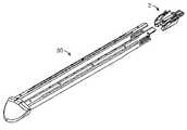
- FIG. 2is a perspective view of an exemplary surgical staple cartridge with the wedge assembly of FIG. 1 in an initial pre-deployment position.
- FIG. 3is an exploded view of FIG. 2 , showing the wedge assembly of FIG. 1 spaced apart from and aligned with the surgical staple cartridge.
- FIG. 4is a perspective view of the exemplary surgical staple cartridge of FIG. 2 , with the cap of the surgical staple cartridge removed.
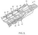
- FIG. 5is a detail view of the proximal end of the exemplary surgical staple cartridge as shown in FIG. 2 .
- the wedge assembly 2includes at least one wedge 4 .
- the wedge assembly 2includes four wedges 4 a , 4 b , 4 c , 4 d .
- the wedge assembly 2may include fewer or more wedges 4 .
- the number of wedges 4corresponds to the number of rows of staples to be deployed, as described in greater detail below.
- the wedges 4 of the embodiment of the wedge assembly 2 shown in FIG. 1may be characterized as the right outer wedge 4 a , right inner wedge 4 b , left inner wedge 4 c , and left outer wedge 4 d .
- the inner wedges 4 b , 4 care laterally closer to the longitudinal centerline of the wedge assembly 2 than the outer wedges 4 a , 4 d .
- the left and right directionsare illustrated in FIG. 1 for clarity. The directions of left and right are selected here to correspond to left and right as perceived by a user. Similarly, the proximal and distal directions, as conventionally understood in the art, are identified in FIG. 1 .
- Each wedge 4may include an upper surface 6 that includes a nose 8 , a plateau 10 , and a shear bump 12 .
- the shape of the surface 6is related to the deployment of staples, as described in greater detail below.
- the nose 8may be curved upward in the distal direction, and may be substantially convex. Alternately, the nose 8 may be curved or shaped in any other suitable manner.
- the plateau 10Distal to the nose 8 , the plateau 10 may be substantially planar and substantially flat. The plateau 10 may be substantially parallel to the longitudinal centerline of the wedge assembly 2 . As seen in FIG.
- the plateaus 10 of the lateral-most wedges 4may be longer than the plateaus 10 of the inner wedges 4 b , 4 c .
- this difference in length between the plateaus 10 of the lateral-most wedges 4 a , 4 d and the remaining wedges 4 b , 4 ccauses greater force to be applied to staples 42 in the outer rows than to staples 42 in the inner rows, and also causes the staples 42 in the outer rows to deploy at a different time than staples 42 in the inner rows.
- the shear bump 12is higher than the plateau 10 .
- the shear bump 12may be positioned at the proximal end of the upper surface 6 of the corresponding wedge 4 . Alternately, the shear bump 12 may be spaced distally from the proximal end of the corresponding wedge 4 .
- the shear bump 12may include a ramp 14 that extends upward in the proximal direction from the plateau 10 .
- the ramp 14may be generally planar, or may be curved or shaped in any other suitable manner.
- the shear bump 12may include a bump plateau 16 that may be substantially planar and substantially flat. In some embodiments, the bump plateau 16 may be substantially parallel to the plateau 10 and thus parallel to the longitudinal axis of the wedge assembly 2 .
- the wedges 4are spaced laterally apart from one another.
- the wedges 4may be angled relative to the longitudinal centerline of the wedge assembly 2 such that the shear bumps on the lateral-most wedges 4 (here, the right outer wedge 4 a and the left outer wedge 4 d ) are spaced laterally apart a distance greater than the distance between the lower edges 18 of the lateral-most wedges 4 .
- the angle between the wedges 4 and the longitudinal centerline of the wedge assembly 2may be selected such that the bump plateau 16 of each wedge 4 is substantially parallel to the upper surface 32 of the cartridge 30 through which the wedge 4 is slidable.
- each of the shear bumps 12has substantially the same length.
- the term “length”refers to a measurement along the longitudinal axis (i.e., the axis along which the proximal and distal directions are defined).
- each bump plateau 16may have substantially the same length.
- the shear bumps 12may be longitudinally aligned with one another, within a distance equal to the length of a shear bump 12 . That is, each shear bump 12 is positioned at a location in the longitudinal direction that is less than or equal to the position of the other shear bumps 12 .
- any reference point on the shear bumps 12may be utilized for measuring this alignment, as long as the same reference point is used for each shear bump 12 (e.g., the proximal end of the bump plateau 16 ).
- the shear bumps 12may be aligned more closely, within a selected length less than the length of a shear bump 12 .
- at least one shear bump 12has a different length and/or shape that at least one other shear bump 12 .
- the wedge assembly 2may include a knife platform 20 from which a knife (not shown) may extend in some embodiments. In this way, as the wedge assembly 2 moves distally to deploy staples, the knife cuts tissue between sets of staples.
- the knife platform 20may be positioned substantially at the lateral center of the wedge assembly 2 .
- FIG. 3shows the wedge assembly moved proximally away from its initial position relative to the cartridge 30 .
- the wedge assembly 2is initially in a proximal position relative to the cartridge 30 and moves distally to deploy staples, as described in greater detail below.
- the wedge assembly 2is initially in a distal position relative to the cartridge 30 and moves proximally to deploy staples.
- the cartridge 30includes an upper surface 32 .
- the upper surface 32may include two lateral sides 32 a .
- the upper surface 32also may include a centerpiece 32 b that separates the two lateral sides 32 a .
- the centerpiece 32 bmay be planar and substantially horizontal.
- Each lateral side 32 amay be planar, and may angle downward away from its junction with the centerpiece 32 b . Each lateral side 32 a may angle downward away from its junction with the centerpiece 32 b by substantially the same angle. Alternately, one lateral side 32 a may angle downward away from its junction with the centerpiece 32 b by a different angle than the other.
- the upper surface 32may have any other suitable shape. For example, the entire upper surface 32 may be planar and substantially horizontal; the upper surface 32 may include additional lateral sides 32 a ; and/or the upper surface 32 may be curved in whole or in part.
- the cartridge 30includes a tip 34 that may be straight (as shown) or that may be curved for ease of tissue dissection.
- the upper surface 32 of the cartridge 30includes a plurality of apertures 36 defined therein. Referring also to FIG. 5 , the positions of the apertures 36 correspond to the positions of the staples 42 within the cartridge 30 , because the apertures 36 provide openings for the staples 42 to be deployed out of the cartridge 30 into tissue.
- FIGS. 4-5show the wedge assembly 2 in an initial position relative to staples 42 in the cartridge 30 .
- the staples 42are fixed to a staple strip 40 at only a single end 46 ; the other end 44 is free.
- the junction between the fixed end 46 of each staple 42 and the staple strip 40forms a frangible connection therebetween.
- the staple strip 40 and staples 42may be configured substantially as described in commonly-assigned U.S. Pat. No. 7,988,026, which is incorporated by reference herein in its entirety.
- Each staple strip 40has two lateral edges, and each staple strip 40 may have a row of staples 42 extending from each of its two lateral edges.
- the fixed ends 46 of the staples 42 in one rowmay extend from longitudinal positions along the staple strip 40 that are longitudinally offset from the fixed ends 46 of the staples 42 in the other row extending from the staple strip 40 , such that no staple 42 extends from the same longitudinal location on the staple strip 40 as another staple 42 .
- This arrangement of staples 42 along a staple strip 40is referred to as a “staggered” arrangement of staples 42 , such that staples 42 in adjacent rows extending from a staple strip 40 are staggered relative to one another. Such staggering of the staples 42 promotes hemostasis in tissue into which the staples 42 are deployed.
- the apertures 36 on each lateral side of the cartridge 30are staggered relative to one another in the same manner as the corresponding staples 42 .
- two rows of staples 42are provided on each lateral side of the cartridge 30 , such that the staples 42 are arranged in four longitudinally-extending rows in the cartridge 30 , and the staples 42 and corresponding apertures 36 on each individual lateral side are staggered.
- the staples 42 and corresponding apertures 36may be staggered relative to one another laterally across the entire upper surface 32 of the cartridge 30 .
- more than two rows of staples 42are provided on each lateral side of the cartridge 30 , and adjacent rows of staples 42 and corresponding apertures 36 on each individual lateral side are staggered relative to one another.
- staples 42may be arranged in six longitudinally-extending rows in the cartridge 30 , and adjacent rows of staples 42 and corresponding apertures 36 on each individual lateral side are staggered relative to one another.
- the cartridge 30is detachably held by a receiver, which is part of an end effector of a surgical stapler.
- the end effectorincludes an anvil opposed to the receiver. At least one of the anvil and receiver is rotatable relative to the other in order to clamp tissue with the end effector and release tissue from the end effector.
- a receiver, anvil, end effector and surgical stapleris described in commonly-assigned U.S. Pat. No. 9,004,339, which is incorporated by reference herein in its entirety.
- the cartridge 30is permanently fixed to and/or nondetachable from the receiver or the end effector.
- the cartridge 30is not used, and the wedge assembly 2 is slidable through a fixed structure in the end effector of a single-use surgical stapler, where the staples 42 are held in that fixed structure.
- a fresh cartridge 30is ready for deployment, as seen in FIG. 2 .
- the wedge assembly 2that is initially positioned at the proximal end of the cartridge 30 is urged distally.
- the wedge assembly 2is initially positioned at the distal end of the cartridge 30 and is urged proximally.
- the motion of the wedge assembly 2may be caused by actuation of one or more controls on a handle of a surgical stapler, such as described in commonly-assigned U.S. Pat. No. 7,988,026.
- each wedge 4sequentially and directly contacts one or more of the staples 42 in a single longitudinally-extending row, in a manner that may be similar to that described in commonly-assigned U.S. Pat. No. 7,988,026.
- the nose 8 of a wedge 4contacts the most-proximal staple 42 in a row.
- the shape of the nose 8begins to rotate the staple 42 about the joint at which the fixed end 46 of the staple 42 is affixed to the staple strip 40 .
- the free end 44 of the staple 42begins to rotate out of the corresponding aperture 36 in the upper surface 32 of the cartridge 30 .
- the nose 8moves distally out of engagement with the staple 42 , and the plateau 10 engages the staple 42 .
- Engagement between the plateau 10 and the staple 42 along the length of the plateau 10causes the staple 42 to continue to rotate about the joint at which the fixed end 46 of the staple 42 is affixed to the staple strip 40 , and causes the free end 44 of the staple 42 to continue to rotate out of the corresponding aperture 36 in the upper surface 32 of the cartridge 30 .
- Contact between the plateau 10 and the staple 42exerts a force on the staple 42 .
- the total force exerted on the staple 42 by the plateau 10 over timeis directly proportional to the length of the plateau 10 —the longer the plateau 10 , the greater the force exerted on the staple 42 , and the shorter the plateau 10 , the lesser the force exerted on the staple 42 .
- the substantially completed rotation of the staple 42 about the joint at which the fixed end 46 of the staple 42 is affixed to the staple strip 40work-hardened the joint, such that the joint is more susceptible to fracture upon the application of shear force thereto. If engagement between the ramp 14 and the staple 42 does not shear or otherwise break the staple 42 from the staple strip 40 , then the bump plateau 16 next engages the staple 42 during the continued distal motion of the wedge 4 , and then shears or otherwise breaks the staple 42 from the staple strip 40 .
- the wedge 4continues to move distally, and engages the next most distal staple 42 in the row in the manner described earlier in this paragraph. As the wedge 4 continues to move distally, it sequentially engages some or all of the remaining staples 42 in the row.
- Each wedge 4sequentially engages the staples 42 in a row, substantially in the same manner as described in the previous paragraph.
- the inner wedges 4 b , 4 cengage the inner rows of staples 42
- the outer wedge 4 a , 4 dengage the outer rows of staples.
- staples 42 in adjacent rows extending from a staple strip 40are staggered relative to one another.
- the shear bumps 12may be longitudinally aligned with one another, within a distance equal to the length of a shear bump 12 .
- a first set of wedges 4directly contacts a first set of staples 42 to form and then break off those staples 42 from the staple strip 40 .
- the number of staples 42 in that first setis less than the number of rows of staples 42 .
- a second set of wedges 4directly contacts a second set of staples 42 to form and then break off those staples 42 from the staple strip 40 .
- the number of staples 42 in that second setis less than the number of rows of staples 42 .
- the number of staples 42 in the first setequals the number of staples 42 in the second set.
- the first set of staples 42may include two staples and the second set of staples 42 may include two staples.
- the wedges 4then may continue to move, and to contact a subsequent first set of staples 42 and subsequent second set of staples 42 , until deployment of all of the staples 42 desired to be deployed is complete.
- the first set of staples 42may come from the inner rows
- the second set of staples 42may come from the outer rows.
- the first set of staples 42may come from the outer rows
- the second set of staples 42may come from the inner rows.
- Contacting wedges 4 directly against a first set of staples 42causes those staples 42 to rotate substantially about a first angle.
- the amount of rotationis proportional to the length of the plateau 10 on each of the wedges 4 .
- the plateaus 10 on the wedges 4 that contact the first set of staples 42are shorter than the plateaus 10 on the wedges 4 that contact the second set of staples 42 .
- the inner wedges 4 b , 4 chave shorter plateaus 10 than the outer wedges 4 a , 4 d .
- the inner wedges 4 b , 4 ccontact the first set of staples 42 .
- contacting wedges 4 directly against the second set of staples 42causes those staples 42 to rotate substantially about a second angle that is greater than the first angle.
- the plateaus 10 on the wedges 4 that contact the first set of staples 42are longer than the plateaus 10 on the wedges 4 that contact the second set of staples 42 , such that contacting wedges 4 directly against the second set of staples 42 causes those staples 42 to rotate substantially about a second angle that is less than the first angle.
- each plateau 10is also proportional to the amount of force applied by the wedge 4 to a staple 42 ; the longer the plateau 10 , the more force is applied to the staple 42 .
- the plateaus 10 on the wedges 4 that contact the first set of staples 42are shorter than the plateaus 10 on the wedges 4 that contact the second set of staples 42 . Consequently, contacting wedges 4 directly against the second set of staples 42 applies a second force to those staples 42 that is greater than a first force applied to the first set of staples 42 .
- the plateaus 10 on the wedges 4 that contact the first set of staples 42are longer than the plateaus 10 on the wedges 4 that contact the second set of staples 42 , such that contacting wedges 4 directly against the second set of staples 42 applies a second force to those staples 42 that is less than a first force applied to the first set of staples 42 .
- a wedge 4 with a longer plateau 10applies more force to a staple 42 , over a longer time, than a wedge 4 with a shorter plateau 10 .
- the shear bumps 12shear off the staples 42 from the staple strip 40 after application of force to the staple 42 from contact with the plateau 10 .
- the differential lengths of the plateaus 10also controls the timing of deployment of the staples 42 .
- all of the wedges 4 of the wedge assembly 2engage staples 42 at substantially the same time, and staples 42 contacted by the inner wedges 4 b , 4 c with the shorter plateaus 10 are deployed before staples contacted by the outer wedges 4 a , 4 d with the longer plateaus 10 .
- the staples 42 engaged by the wedges 4 with the shorter plateaus 10finish engagement with the plateaus 10 and are sheared off by the shear bumps 12 at a time when the staples 42 engaged by the wedges 4 with the longer plateaus 10 are still engaged with those longer plateaus 10 .
- the first two staples 42 in the inner rowsare deployed before the first two staples 42 in the outer rows. Further, the staples 42 engaged by the wedges 4 with the longer plateaus 10 contact those plateaus 10 for a longer time than the staples 42 engaged by the wedges 4 with the shorter plateaus 10 .
- the longer plateaus 10may be located on the inner wedges 4 b , 4 c and the shorter plateaus 10 may be located on the outer wedges 4 a , 4 d , such that the staples 42 in the outer rows are deployed before the first two staples 42 in the inner rows.
- the longer plateaus 10may be divided across an inner and an outer wedge 4 , with the shorter plateaus 10 positioned on the other inner and outer wedge 4 . In all of these configurations, the wedge assembly 2 starts deployment of a set of four staples 42 across four rows at substantially the same time, and finishes deployment of two staples 42 while the other two staples 42 in the set are still being deployed.
- wedges 4may apply a first force to a first set of staples 42 while other wedges 4 apply no force to a second set of staples 42 , and then wedges 4 apply no force to a first set of staples while other wedges 4 apply force to a second set of staples 42 .
- the staples 42 in a roware spaced longitudinally further apart from one another and/or the wedges 4 are shorter.
Landscapes
- Health & Medical Sciences (AREA)
- Life Sciences & Earth Sciences (AREA)
- Surgery (AREA)
- Heart & Thoracic Surgery (AREA)
- Engineering & Computer Science (AREA)
- Biomedical Technology (AREA)
- Nuclear Medicine, Radiotherapy & Molecular Imaging (AREA)
- Medical Informatics (AREA)
- Molecular Biology (AREA)
- Animal Behavior & Ethology (AREA)
- General Health & Medical Sciences (AREA)
- Public Health (AREA)
- Veterinary Medicine (AREA)
- Surgical Instruments (AREA)
Abstract
Description
Claims (20)
Priority Applications (6)
| Application Number | Priority Date | Filing Date | Title |
|---|---|---|---|
| US15/640,301US10433843B2 (en) | 2017-06-30 | 2017-06-30 | Wedge assembly for surgical staple cartridge |
| PCT/EP2018/067623WO2019002568A1 (en) | 2017-06-30 | 2018-06-29 | Wedge assembly for surgical staple cartridge |
| CN201880040608.3ACN110785127B (en) | 2017-06-30 | 2018-06-29 | Wedge assembly for surgical staple cartridge |
| EP18737216.4AEP3644871B1 (en) | 2017-06-30 | 2018-06-29 | Wedge assembly for surgical staple cartridge |
| ES18737216TES2880681T3 (en) | 2017-06-30 | 2018-06-29 | Wedge Mount for Surgical Staple Cartridge |
| US16/623,902US20200146677A1 (en) | 2017-06-30 | 2018-06-29 | Wedge assembly for surgical staple cartridge |
Applications Claiming Priority (1)
| Application Number | Priority Date | Filing Date | Title |
|---|---|---|---|
| US15/640,301US10433843B2 (en) | 2017-06-30 | 2017-06-30 | Wedge assembly for surgical staple cartridge |
Related Child Applications (1)
| Application Number | Title | Priority Date | Filing Date |
|---|---|---|---|
| US16/623,902ContinuationUS20200146677A1 (en) | 2017-06-30 | 2018-06-29 | Wedge assembly for surgical staple cartridge |
Publications (2)
| Publication Number | Publication Date |
|---|---|
| US20190000480A1 US20190000480A1 (en) | 2019-01-03 |
| US10433843B2true US10433843B2 (en) | 2019-10-08 |
Family
ID=62816541
Family Applications (2)
| Application Number | Title | Priority Date | Filing Date |
|---|---|---|---|
| US15/640,301Active2038-02-28US10433843B2 (en) | 2017-06-30 | 2017-06-30 | Wedge assembly for surgical staple cartridge |
| US16/623,902AbandonedUS20200146677A1 (en) | 2017-06-30 | 2018-06-29 | Wedge assembly for surgical staple cartridge |
Family Applications After (1)
| Application Number | Title | Priority Date | Filing Date |
|---|---|---|---|
| US16/623,902AbandonedUS20200146677A1 (en) | 2017-06-30 | 2018-06-29 | Wedge assembly for surgical staple cartridge |
Country Status (5)
| Country | Link |
|---|---|
| US (2) | US10433843B2 (en) |
| EP (1) | EP3644871B1 (en) |
| CN (1) | CN110785127B (en) |
| ES (1) | ES2880681T3 (en) |
| WO (1) | WO2019002568A1 (en) |
Cited By (5)
| Publication number | Priority date | Publication date | Assignee | Title |
|---|---|---|---|---|
| US20220133316A1 (en)* | 2020-11-04 | 2022-05-05 | Ethicon Llc | Surgical stapler end effector sled having cartridge biasing feature |
| US12082810B2 (en) | 2020-11-04 | 2024-09-10 | Cilag Gmbh International | Surgical stapler end effector sled having staple driver support feature |
| US12133647B2 (en) | 2020-11-04 | 2024-11-05 | Cilag Gmbh International | Surgical stapler end effector sled having cartridge wall support feature |
| USD1072250S1 (en) | 2020-11-04 | 2025-04-22 | Cilag Gmbh International | Surgical stapler end effector sled |
| USD1084333S1 (en) | 2020-11-04 | 2025-07-15 | Cilag Gmbh International | Surgical stapler end effector sled |
Families Citing this family (5)
| Publication number | Priority date | Publication date | Assignee | Title |
|---|---|---|---|---|
| CN111789645B (en)* | 2019-04-09 | 2025-03-25 | 天臣国际医疗科技股份有限公司 | Nail cartridge assembly and medical stapler including the same |
| US11707278B2 (en)* | 2020-03-06 | 2023-07-25 | Covidien Lp | Surgical stapler tool assembly to minimize bleeding |
| US11832814B2 (en)* | 2020-11-04 | 2023-12-05 | Cilag Gmbh International | Surgical stapler end effector sled having tapered distal end |
| CN115886910A (en)* | 2021-08-31 | 2023-04-04 | 天臣国际医疗科技股份有限公司 | Nail bin assembly and medical anastomat |
| KR20240044486A (en)* | 2021-08-31 | 2024-04-04 | 터치스톤 인터내셔널 메디컬 사이언스 씨오., 엘티디. | Staple cartridge assemblies, staple heads and medical staplers |
Citations (22)
| Publication number | Priority date | Publication date | Assignee | Title |
|---|---|---|---|---|
| US5941442A (en)* | 1995-10-27 | 1999-08-24 | United States Surgical | Surgical stapler |
| US7635074B2 (en)* | 2005-10-04 | 2009-12-22 | Tyco Healthcare Group Lp | Staple drive assembly |
| US7641091B2 (en)* | 2005-10-04 | 2010-01-05 | Tyco Healthcare Group Lp | Staple drive assembly |
| US7669746B2 (en)* | 2005-08-31 | 2010-03-02 | Ethicon Endo-Surgery, Inc. | Staple cartridges for forming staples having differing formed staple heights |
| US7988026B2 (en) | 2007-09-06 | 2011-08-02 | Cardica, Inc. | Endocutter with staple feed |
| US8127976B2 (en)* | 2009-05-08 | 2012-03-06 | Tyco Healthcare Group Lp | Stapler cartridge and channel interlock |
| US8261958B1 (en)* | 2010-01-06 | 2012-09-11 | Cardica, Inc. | Stapler cartridge with staples frangibly affixed thereto |
| US8276594B2 (en)* | 2008-06-06 | 2012-10-02 | Tyco Healthcare Group Lp | Knife lockout mechanisms for surgical instrument |
| US8365973B1 (en)* | 2009-06-03 | 2013-02-05 | Cardica, Inc. | D-shaped surgical staples |
| US8464922B2 (en)* | 2008-05-09 | 2013-06-18 | Covidien Lp | Variable compression surgical fastener cartridge |
| US8631990B1 (en)* | 2011-04-25 | 2014-01-21 | Cardica, Inc. | Staple trap for surgical stapler |
| US8789739B2 (en)* | 2011-09-06 | 2014-07-29 | Ethicon Endo-Surgery, Inc. | Continuous stapling instrument |
| US8893950B2 (en)* | 2009-04-16 | 2014-11-25 | Covidien Lp | Surgical apparatus for applying tissue fasteners |
| US9004339B1 (en) | 2009-05-26 | 2015-04-14 | Cardica, Inc. | Cartridgizable feeder belt for surgical stapler |
| US9016539B2 (en)* | 2011-10-25 | 2015-04-28 | Covidien Lp | Multi-use loading unit |
| US9113870B2 (en)* | 2008-05-09 | 2015-08-25 | Covidien Lp | Variable compression surgical fastener apparatus |
| US9307986B2 (en)* | 2013-03-01 | 2016-04-12 | Ethicon Endo-Surgery, Llc | Surgical instrument soft stop |
| US9629628B2 (en)* | 2013-03-13 | 2017-04-25 | Covidien Lp | Surgical stapling apparatus |
| US9757130B2 (en)* | 2007-02-28 | 2017-09-12 | Ethicon Llc | Stapling assembly for forming different formed staple heights |
| US9788835B2 (en)* | 2014-09-02 | 2017-10-17 | Ethicon Llc | Devices and methods for facilitating ejection of surgical fasteners from cartridges |
| US20170303923A1 (en)* | 2016-04-20 | 2017-10-26 | Ethicon Endo-Surgery, Llc | Compliant compensation features for end effector of surgical stapling instrument |
| US9855042B1 (en)* | 2016-07-08 | 2018-01-02 | Medi Tulip Co., Ltd | End effector of surgical linear stapler |
Family Cites Families (10)
| Publication number | Priority date | Publication date | Assignee | Title |
|---|---|---|---|---|
| US7954686B2 (en)* | 2008-09-19 | 2011-06-07 | Ethicon Endo-Surgery, Inc. | Surgical stapler with apparatus for adjusting staple height |
| US8439246B1 (en)* | 2010-07-20 | 2013-05-14 | Cardica, Inc. | Surgical stapler with cartridge-adjustable clamp gap |
| EP2833800A4 (en)* | 2012-04-02 | 2016-01-13 | Cardica Inc | Surgical stapler with superelastic staples |
| EP2833802A4 (en)* | 2012-04-04 | 2015-11-18 | Cardica Inc | Surgical staple cartridge with bendable tip |
| US9668729B2 (en)* | 2013-03-13 | 2017-06-06 | Covidien Lp | Surgical stapling apparatus |
| US9655613B2 (en)* | 2013-03-14 | 2017-05-23 | Dextera Surgical Inc. | Beltless staple chain for cartridge and cartridgeless surgical staplers |
| US10327764B2 (en)* | 2014-09-26 | 2019-06-25 | Ethicon Llc | Method for creating a flexible staple line |
| US9848876B2 (en)* | 2014-09-02 | 2017-12-26 | Ethicon Llc | Devices and methods for facilitating ejection of surgical fasteners from cartridges |
| US10517594B2 (en)* | 2014-10-29 | 2019-12-31 | Ethicon Llc | Cartridge assemblies for surgical staplers |
| US10463368B2 (en)* | 2015-04-10 | 2019-11-05 | Covidien Lp | Endoscopic stapler |
- 2017
- 2017-06-30USUS15/640,301patent/US10433843B2/enactiveActive
- 2018
- 2018-06-29ESES18737216Tpatent/ES2880681T3/enactiveActive
- 2018-06-29EPEP18737216.4Apatent/EP3644871B1/enactiveActive
- 2018-06-29WOPCT/EP2018/067623patent/WO2019002568A1/ennot_activeCeased
- 2018-06-29CNCN201880040608.3Apatent/CN110785127B/enactiveActive
- 2018-06-29USUS16/623,902patent/US20200146677A1/ennot_activeAbandoned
Patent Citations (23)
| Publication number | Priority date | Publication date | Assignee | Title |
|---|---|---|---|---|
| US5941442A (en)* | 1995-10-27 | 1999-08-24 | United States Surgical | Surgical stapler |
| US7669746B2 (en)* | 2005-08-31 | 2010-03-02 | Ethicon Endo-Surgery, Inc. | Staple cartridges for forming staples having differing formed staple heights |
| US7635074B2 (en)* | 2005-10-04 | 2009-12-22 | Tyco Healthcare Group Lp | Staple drive assembly |
| US7641091B2 (en)* | 2005-10-04 | 2010-01-05 | Tyco Healthcare Group Lp | Staple drive assembly |
| US9757130B2 (en)* | 2007-02-28 | 2017-09-12 | Ethicon Llc | Stapling assembly for forming different formed staple heights |
| US7988026B2 (en) | 2007-09-06 | 2011-08-02 | Cardica, Inc. | Endocutter with staple feed |
| US9867616B2 (en)* | 2008-05-09 | 2018-01-16 | Covidien Lp | Variable compression surgical fastener cartridge |
| US8464922B2 (en)* | 2008-05-09 | 2013-06-18 | Covidien Lp | Variable compression surgical fastener cartridge |
| US9113870B2 (en)* | 2008-05-09 | 2015-08-25 | Covidien Lp | Variable compression surgical fastener apparatus |
| US8276594B2 (en)* | 2008-06-06 | 2012-10-02 | Tyco Healthcare Group Lp | Knife lockout mechanisms for surgical instrument |
| US8893950B2 (en)* | 2009-04-16 | 2014-11-25 | Covidien Lp | Surgical apparatus for applying tissue fasteners |
| US8127976B2 (en)* | 2009-05-08 | 2012-03-06 | Tyco Healthcare Group Lp | Stapler cartridge and channel interlock |
| US9004339B1 (en) | 2009-05-26 | 2015-04-14 | Cardica, Inc. | Cartridgizable feeder belt for surgical stapler |
| US8365973B1 (en)* | 2009-06-03 | 2013-02-05 | Cardica, Inc. | D-shaped surgical staples |
| US8261958B1 (en)* | 2010-01-06 | 2012-09-11 | Cardica, Inc. | Stapler cartridge with staples frangibly affixed thereto |
| US8631990B1 (en)* | 2011-04-25 | 2014-01-21 | Cardica, Inc. | Staple trap for surgical stapler |
| US8789739B2 (en)* | 2011-09-06 | 2014-07-29 | Ethicon Endo-Surgery, Inc. | Continuous stapling instrument |
| US9016539B2 (en)* | 2011-10-25 | 2015-04-28 | Covidien Lp | Multi-use loading unit |
| US9307986B2 (en)* | 2013-03-01 | 2016-04-12 | Ethicon Endo-Surgery, Llc | Surgical instrument soft stop |
| US9629628B2 (en)* | 2013-03-13 | 2017-04-25 | Covidien Lp | Surgical stapling apparatus |
| US9788835B2 (en)* | 2014-09-02 | 2017-10-17 | Ethicon Llc | Devices and methods for facilitating ejection of surgical fasteners from cartridges |
| US20170303923A1 (en)* | 2016-04-20 | 2017-10-26 | Ethicon Endo-Surgery, Llc | Compliant compensation features for end effector of surgical stapling instrument |
| US9855042B1 (en)* | 2016-07-08 | 2018-01-02 | Medi Tulip Co., Ltd | End effector of surgical linear stapler |
Cited By (7)
| Publication number | Priority date | Publication date | Assignee | Title |
|---|---|---|---|---|
| US20220133316A1 (en)* | 2020-11-04 | 2022-05-05 | Ethicon Llc | Surgical stapler end effector sled having cartridge biasing feature |
| US12064112B2 (en)* | 2020-11-04 | 2024-08-20 | Cilag Gmbh International | Surgical stapler end effector sled having cartridge biasing feature |
| US12082810B2 (en) | 2020-11-04 | 2024-09-10 | Cilag Gmbh International | Surgical stapler end effector sled having staple driver support feature |
| US12089843B2 (en) | 2020-11-04 | 2024-09-17 | Cilag Gmbh International | Surgical stapler end effector sled having staple driver support feature |
| US12133647B2 (en) | 2020-11-04 | 2024-11-05 | Cilag Gmbh International | Surgical stapler end effector sled having cartridge wall support feature |
| USD1072250S1 (en) | 2020-11-04 | 2025-04-22 | Cilag Gmbh International | Surgical stapler end effector sled |
| USD1084333S1 (en) | 2020-11-04 | 2025-07-15 | Cilag Gmbh International | Surgical stapler end effector sled |
Also Published As
| Publication number | Publication date |
|---|---|
| EP3644871A1 (en) | 2020-05-06 |
| US20200146677A1 (en) | 2020-05-14 |
| CN110785127B (en) | 2023-02-17 |
| WO2019002568A1 (en) | 2019-01-03 |
| ES2880681T3 (en) | 2021-11-25 |
| CN110785127A (en) | 2020-02-11 |
| EP3644871B1 (en) | 2021-05-05 |
| US20190000480A1 (en) | 2019-01-03 |
Similar Documents
| Publication | Publication Date | Title |
|---|---|---|
| US10433843B2 (en) | Wedge assembly for surgical staple cartridge | |
| US20230329712A1 (en) | Surgical stapling device with floating staple cartridge | |
| CN102028514B (en) | Dual staple pusher pairs in a three-row stapler | |
| US10172614B1 (en) | Feeder belt actuation mechanism for true multi-fire surgical stapler | |
| US8348127B2 (en) | Surgical fastener applying apparatus | |
| US9004339B1 (en) | Cartridgizable feeder belt for surgical stapler | |
| US8056789B1 (en) | Staple and feeder belt configurations for surgical stapler | |
| US5931847A (en) | Surgical cutting instrument with improved cutting edge | |
| US5397324A (en) | Surgical stapler instrument and method for vascular hemostasis | |
| US8261958B1 (en) | Stapler cartridge with staples frangibly affixed thereto | |
| EP2116198B1 (en) | Varying tissue compression with an anvil configuration | |
| CN110381851A (en) | Operation stitching device with variable height staple propeller | |
| EP2319425A2 (en) | Surgical stapler | |
| US20150060522A1 (en) | Surgical Stapler | |
| US20220031312A1 (en) | Surgical stapling device with staple cartridge having dummy portion | |
| CN111789644B (en) | Nail cartridge assembly and medical stapler including the same | |
| CN120129502A (en) | Surgical suturing device with tissue gap control | |
| EP3446646A1 (en) | Circular stapling device with offset spline tip | |
| US11896233B2 (en) | Circular stapling device | |
| CN216933330U (en) | Nail bin assembly for anastomat and anastomat | |
| WO2025191400A1 (en) | Surgical stapling device with tissue gap control |
Legal Events
| Date | Code | Title | Description |
|---|---|---|---|
| STPP | Information on status: patent application and granting procedure in general | Free format text:DOCKETED NEW CASE - READY FOR EXAMINATION | |
| AS | Assignment | Owner name:AESCULAP AG, GERMANY Free format text:ASSET PURCHASE AGREEMENT;ASSIGNOR:AESDEX, LLC;REEL/FRAME:045870/0567 Effective date:20180220 Owner name:AESDEX, LLC, PENNSYLVANIA Free format text:ASSIGNMENT OF ASSIGNORS INTEREST;ASSIGNOR:DEXTERA SURGICAL INC.;REEL/FRAME:045870/0478 Effective date:20180214 | |
| AS | Assignment | Owner name:AESCULAP AG, GERMANY Free format text:ASSIGNMENT OF ASSIGNORS INTEREST;ASSIGNOR:YEE, KRISTOPHER J.;REEL/FRAME:046458/0026 Effective date:20180524 | |
| STPP | Information on status: patent application and granting procedure in general | Free format text:NOTICE OF ALLOWANCE MAILED -- APPLICATION RECEIVED IN OFFICE OF PUBLICATIONS | |
| STPP | Information on status: patent application and granting procedure in general | Free format text:AWAITING TC RESP, ISSUE FEE PAYMENT VERIFIED | |
| STPP | Information on status: patent application and granting procedure in general | Free format text:PUBLICATIONS -- ISSUE FEE PAYMENT VERIFIED | |
| STCF | Information on status: patent grant | Free format text:PATENTED CASE | |
| MAFP | Maintenance fee payment | Free format text:PAYMENT OF MAINTENANCE FEE, 4TH YEAR, LARGE ENTITY (ORIGINAL EVENT CODE: M1551); ENTITY STATUS OF PATENT OWNER: LARGE ENTITY Year of fee payment:4 | |
| AS | Assignment | Owner name:TOUCHSTONE INTERNATIONAL MEDICAL SCIENCE CO., LTD., CHINA Free format text:ASSIGNMENT OF ASSIGNORS INTEREST;ASSIGNOR:AESCULAP AG;REEL/FRAME:065536/0326 Effective date:20230731 |