US10432013B2 - Windshield solar mount assembly - Google Patents
Windshield solar mount assemblyDownload PDFInfo
- Publication number
- US10432013B2 US10432013B2US15/092,312US201615092312AUS10432013B2US 10432013 B2US10432013 B2US 10432013B2US 201615092312 AUS201615092312 AUS 201615092312AUS 10432013 B2US10432013 B2US 10432013B2
- Authority
- US
- United States
- Prior art keywords
- electronic device
- portable electronic
- interface
- mounting
- rechargeable battery
- Prior art date
- Legal status (The legal status is an assumption and is not a legal conclusion. Google has not performed a legal analysis and makes no representation as to the accuracy of the status listed.)
- Active, expires
Links
- 230000001681protective effectEffects0.000claimsdescription49
- 230000008878couplingEffects0.000claimsdescription5
- 238000010168coupling processMethods0.000claimsdescription5
- 238000005859coupling reactionMethods0.000claimsdescription5
- 238000000034methodMethods0.000claimsdescription4
- 238000012546transferMethods0.000claimsdescription3
- 239000000463materialSubstances0.000description12
- WHXSMMKQMYFTQS-UHFFFAOYSA-NLithiumChemical compound[Li]WHXSMMKQMYFTQS-UHFFFAOYSA-N0.000description3
- 229910052744lithiumInorganic materials0.000description3
- 239000004677NylonSubstances0.000description2
- 239000000853adhesiveSubstances0.000description2
- 230000001070adhesive effectEffects0.000description2
- 238000004891communicationMethods0.000description2
- 229920001778nylonPolymers0.000description2
- 230000000007visual effectEffects0.000description2
- HBBGRARXTFLTSG-UHFFFAOYSA-NLithium ionChemical compound[Li+]HBBGRARXTFLTSG-UHFFFAOYSA-N0.000description1
- BPKGOZPBGXJDEP-UHFFFAOYSA-N[C].[Zn]Chemical compound[C].[Zn]BPKGOZPBGXJDEP-UHFFFAOYSA-N0.000description1
- 238000005299abrasionMethods0.000description1
- 230000001133accelerationEffects0.000description1
- 238000004378air conditioningMethods0.000description1
- 230000000712assemblyEffects0.000description1
- 238000000429assemblyMethods0.000description1
- 239000003990capacitorSubstances0.000description1
- 230000001413cellular effectEffects0.000description1
- 238000006073displacement reactionMethods0.000description1
- 229920001971elastomerPolymers0.000description1
- 239000000806elastomerSubstances0.000description1
- 230000005611electricityEffects0.000description1
- 239000000446fuelSubstances0.000description1
- 239000011521glassSubstances0.000description1
- 229910001416lithium ionInorganic materials0.000description1
- 229910052987metal hydrideInorganic materials0.000description1
- 238000012986modificationMethods0.000description1
- 230000004048modificationEffects0.000description1
- 238000012544monitoring processMethods0.000description1
- 230000003287optical effectEffects0.000description1
- 239000004417polycarbonateSubstances0.000description1
- 229920000515polycarbonatePolymers0.000description1
- 229920000642polymerPolymers0.000description1
- 229920002379silicone rubberPolymers0.000description1
- 239000004945silicone rubberSubstances0.000description1
- 239000000126substanceSubstances0.000description1
- 229920001059synthetic polymerPolymers0.000description1
- 229920001169thermoplasticPolymers0.000description1
- 229920002725thermoplastic elastomerPolymers0.000description1
Images


Classifications
- H02J7/355—
- H—ELECTRICITY
- H02—GENERATION; CONVERSION OR DISTRIBUTION OF ELECTRIC POWER
- H02S—GENERATION OF ELECTRIC POWER BY CONVERSION OF INFRARED RADIATION, VISIBLE LIGHT OR ULTRAVIOLET LIGHT, e.g. USING PHOTOVOLTAIC [PV] MODULES
- H02S10/00—PV power plants; Combinations of PV energy systems with other systems for the generation of electric power
- H02S10/40—Mobile PV generator systems
- H—ELECTRICITY
- H02—GENERATION; CONVERSION OR DISTRIBUTION OF ELECTRIC POWER
- H02J—CIRCUIT ARRANGEMENTS OR SYSTEMS FOR SUPPLYING OR DISTRIBUTING ELECTRIC POWER; SYSTEMS FOR STORING ELECTRIC ENERGY
- H02J7/00—Circuit arrangements for charging or depolarising batteries or for supplying loads from batteries
- H02J7/34—Parallel operation in networks using both storage and other DC sources, e.g. providing buffering
- H02J7/35—Parallel operation in networks using both storage and other DC sources, e.g. providing buffering with light sensitive cells
- H—ELECTRICITY
- H02—GENERATION; CONVERSION OR DISTRIBUTION OF ELECTRIC POWER
- H02S—GENERATION OF ELECTRIC POWER BY CONVERSION OF INFRARED RADIATION, VISIBLE LIGHT OR ULTRAVIOLET LIGHT, e.g. USING PHOTOVOLTAIC [PV] MODULES
- H02S20/00—Supporting structures for PV modules
- H02S20/30—Supporting structures being movable or adjustable, e.g. for angle adjustment
- H02J7/0054—
- H—ELECTRICITY
- H02—GENERATION; CONVERSION OR DISTRIBUTION OF ELECTRIC POWER
- H02J—CIRCUIT ARRANGEMENTS OR SYSTEMS FOR SUPPLYING OR DISTRIBUTING ELECTRIC POWER; SYSTEMS FOR STORING ELECTRIC ENERGY
- H02J7/00—Circuit arrangements for charging or depolarising batteries or for supplying loads from batteries
- H02J7/34—Parallel operation in networks using both storage and other DC sources, e.g. providing buffering
- H02J7/342—The other DC source being a battery actively interacting with the first one, i.e. battery to battery charging
- Y—GENERAL TAGGING OF NEW TECHNOLOGICAL DEVELOPMENTS; GENERAL TAGGING OF CROSS-SECTIONAL TECHNOLOGIES SPANNING OVER SEVERAL SECTIONS OF THE IPC; TECHNICAL SUBJECTS COVERED BY FORMER USPC CROSS-REFERENCE ART COLLECTIONS [XRACs] AND DIGESTS
- Y02—TECHNOLOGIES OR APPLICATIONS FOR MITIGATION OR ADAPTATION AGAINST CLIMATE CHANGE
- Y02E—REDUCTION OF GREENHOUSE GAS [GHG] EMISSIONS, RELATED TO ENERGY GENERATION, TRANSMISSION OR DISTRIBUTION
- Y02E10/00—Energy generation through renewable energy sources
- Y02E10/50—Photovoltaic [PV] energy
- Y—GENERAL TAGGING OF NEW TECHNOLOGICAL DEVELOPMENTS; GENERAL TAGGING OF CROSS-SECTIONAL TECHNOLOGIES SPANNING OVER SEVERAL SECTIONS OF THE IPC; TECHNICAL SUBJECTS COVERED BY FORMER USPC CROSS-REFERENCE ART COLLECTIONS [XRACs] AND DIGESTS
- Y02—TECHNOLOGIES OR APPLICATIONS FOR MITIGATION OR ADAPTATION AGAINST CLIMATE CHANGE
- Y02E—REDUCTION OF GREENHOUSE GAS [GHG] EMISSIONS, RELATED TO ENERGY GENERATION, TRANSMISSION OR DISTRIBUTION
- Y02E70/00—Other energy conversion or management systems reducing GHG emissions
- Y02E70/30—Systems combining energy storage with energy generation of non-fossil origin
Definitions
- This disclosurerelates generally to a charging system for a portable electronic device, and more particularly to a charging system that uses ambient light to supply power to the portable electronic device.
- Portable electronic devicesare frequently used in vehicles to entertain or provide assistance to a driver and/or passenger. For example, if a vehicle's radio is not capable of connecting to a cellular or other wireless network, a portable electronic device that can connect to such a network may be connected to the vehicle's existing speakers (via a hard wire or wirelessly using a BLUETOOTH® connection) to stream music in the vehicle. As another example, a portable electronic device may be used to run a navigation application to provide turn-by-turn directions to a destination.
- charging adaptersmay be used with a mounting assembly that secures the portable electronic device in a desired location in the vehicle (for example, mounted to the vehicle's windshield).
- typical charging adaptersrely on cables that extend from the portable electronic device to a portion of the vehicle's dashboard, such as the vehicle's lighter adapter. These cables can prevent the vehicle's driver from viewing instruments or gauges, thereby distracting the driver and endangering the lives of the driver and any passengers.
- Such cablescan also clutter the interior of the vehicle and prevent the driver from accessing features, such as the radio or air conditioning controls. Accordingly, there is a need for a charging system that allows for convenient access and use of a portable electronic device within a vehicle without the clutter and potential for dangerous interference associated with known recharging cables.
- a solar charging system for a portable electronic device including an electrical interfaceincludes a protective case for receiving and partially enclosing the portable electronic device when the portable electronic device is installed in the protective case.
- the solar charging systemalso includes a charging assembly including an electrical connector adapted to be removably coupled to the electrical interface of the portable electronic device such that when the electrical connector is coupled to the electrical interface of the portable electronic device, the electrical connector is electrically coupled to the electrical interface of the portable electronic device.
- the charging assemblyalso includes a rechargeable battery electrically coupled to the electrical connector, and the rechargeable battery is adapted to store a stored electrical power.
- the charging assemblyalso includes a mounting interface to which the protective case can be removably mounted, the mounting interface and the protective case configured such that the electrical connector electrically coupled to the rechargeable battery engages the electrical interface of the installed portable electronic device when the protective case is mounted or coupled to the mounting interface.
- the charging assemblyfurther includes a solar panel configured for receiving ambient light and converting the ambient light to received electrical power.
- the solar panelis electrically coupled to the rechargeable battery such that the received electrical power is configured to be stored in the rechargeable battery as stored electrical power.
- the electrical connectoris electrically coupled to the electrical interface of the installed portable electronic device such that the stored electrical power is provided or conveyed to the portable electronic device.
- the protective caseis not mounted to the mounting interface, the received electrical power is stored in the rechargeable battery as the stored electrical power.
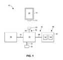
- FIG. 1is a schematic view of an embodiment of a solar charging system
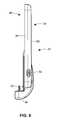
- FIG. 2is a perspective view of an embodiment of a charging assembly of an embodiment of a solar charging system
- FIG. 3is a front view of an embodiment of a protective case enclosing a portable electronic device
- FIG. 4is a rear view of the embodiment of the protective case illustrated in FIG. 3 ;
- FIG. 5is a front perspective view of an embodiment of a mounting interface of an embodiment of a charging assembly
- FIG. 6is a side view of the embodiment of the mounting interface of FIG. 5 ;
- FIG. 7is a back perspective view of the embodiment of the mounting interface of FIG. 5 ;
- FIG. 8is a front perspective view of an embodiment of a solar panel mounting member without an attached solar panel
- FIG. 9is a back perspective view of the embodiment of the solar panel mounting member of FIG. 8 ;
- FIG. 10is a perspective view of an embodiment of a base portion
- FIG. 11is a side view of the embodiment of the base portion of FIG. 10 ;
- FIG. 12is a perspective view of an embodiment of a solar charging system
- FIG. 13is a perspective view of an embodiment of a charging assembly of an embodiment of a solar charging system
- FIG. 14is a perspective view of an embodiment of a charging assembly of an embodiment of a solar charging system.
- FIG. 15is a perspective view of an embodiment of a solar charging system.
- the solar charging system of the present inventionsolves the problems of known charging adapters by charging the portable electronic device while it is used as a navigational tool or as a streaming radio while at the same time minimizing the number of wires that can distract the driver of the vehicle or prevent the driver from seeing a portion of the instrument panel or accessing features in the vehicle.
- one or more solar panelsmay be incorporated into the solar charging system so that ambient light may provide power to the portable electronic device.
- the solar panel(s)eliminate the need for wires to extend between the portable electronic device and the vehicle's dashboard, thereby allowing the vehicle's driver to see and access the entire dashboard.
- the solar panel(s)also may be connected to a rechargeable battery, and the solar panel(s) may charge the rechargeable battery during daylight hours to maintain a full charge in the rechargeable battery. Such a fully charged battery increases the charge rate of the portable electronic device relative to a solar panel alone.
- the portable electronic devicemay be electrically connected to the rechargeable battery to provide power when no or little ambient light is available.
- FIG. 1schematically illustrates an embodiment of a solar charging system 10 provided for a portable electronic device 12 that includes an electrical interface 14 .
- the solar charging system 10includes a protective case 16 for receiving and partially (or at least partially) enclosing the portable electronic device 12 when the portable electronic device 12 is installed in the protective case 16 .
- the solar charging system 10also includes a charging assembly 18 including an electrical connector 20 adapted to be removably coupled to the electrical interface 14 of the portable electronic device 12 such that when the electrical connector 20 is coupled to, connected to, or mated with the electrical interface 14 of the portable electronic device 12 , the electrical connector 20 is electrically coupled to the electrical interface 14 of the portable electronic device 12 .
- the charging assembly 18also includes a rechargeable battery 22 electrically coupled to the electrical connector 20 , and the rechargeable battery 22 is adapted to store a stored electrical power.
- the charging assembly 18also includes a mounting interface 24 to which the protective case 16 can be removably mounted.
- the mounting interface 24 and the protective case 16are configured such that the electrical connector 20 electrically coupled to the rechargeable battery 22 engages the electrical interface 14 of the installed portable electronic device 12 when the protective case 16 is mounted to the mounting interface 24 .
- the charging assembly 18further includes a solar panel 26 configured for receiving ambient light and converting the ambient light to received electrical power.
- the solar panel 26is electrically coupled to the rechargeable battery 22 such that the received electrical power is configured to be stored in the rechargeable battery 22 as stored electrical power (or as a portion of the stored electrical power).
- the electrical connector 20is electrically coupled to the electrical interface 14 of the installed portable electronic device 12 such that the stored electrical power (or at least a portion of the stored electrical power) is provided or conveyed to the portable electronic device 12 .
- the received electrical poweris stored in the rechargeable battery as the stored electrical power (or as a portion of the stored electrical power).
- Received electrical powermay also be stored in the rechargeable battery 22 as the stored electrical power (or as a portion of the stored electrical power) when the protective case 16 is mounted to the mounting interface 24 (or when the electrical connector 20 is electrically coupled to the electrical interface 14 of the portable electronic device 12 ) when an internal battery (not shown) of the portable electronic device 12 is fully charged or when a charging level of the internal battery of the portable electronic device 12 is greater than or equal to a threshold stored charge (e.g., 80% charged, 90% charged, 100% charged).
- a threshold stored chargee.g., 80% charged, 90% charged, 100% charged.
- the protective case 16 for receiving and partially enclosing the portable electronic device 12may be any suitable case that at least partially surrounds the portable electronic device 12 to provide at least some protection for the portable electronic device 12 while allowing access to the electrical interface 14 .
- the protective case 16 for the portable electronic device 12may include an inner liner 28 and an outer shell 30 .
- the inner liner 28may act as a cushion layer and may provide the primary surface(s) for receiving and holding the portable electronic device 12 in the protective case 16 .
- the inner liner 28may contact the portable electronic device 12 on any one or more of a back surface, on one or more side surfaces, and/or on a portion of a front surface of the portable electronic device 12 .
- the inner liner 28may be configured to cushion an installed electronic device from external forces, impacts, sudden acceleration, sudden deceleration, and other forces experienced at outer surfaces of the protective case 16 .
- the inner liner 28may be made of a material that is pliant to allow it to flexibly hold the portable electronic device 12 to reduce movement, shifting, or rattling of the portable electronic device 12 within protective case 16 .
- the inner liner 28may be made of any suitable material that allows for such protection and flexibility, and the inner liner 28 typically comprises a material that is softer than a material of the outer shell 30 .
- the inner liner 28may be made of an elastomer, such as a thermoplastic elastomer or silicone rubber.
- the outer shell 30may also be referred to as a structural layer, a frame, a rigid layer, a bottom shell, and/or a shell of the protective case 16 .
- the outer shell 30may extend around some or all of the outer surface of inner liner 28 .
- the outer shell 30may be manufactured from a material that is harder, more rigid, stiffer, more puncture resistant, more crush resistant, more chemical resistant, and/or more abrasion resistant than the material of inner liner 28 .
- the material of outer shell 30may be any suitable material, such as a thermoplastic polymer or a synthetic polymer, and the material may include polycarbonate, nylon, or glass filled nylon.
- the protective case 16may include an aperture 31 that at least partially surrounds the electrical interface 14 of the portable electronic device 12 when the portable electronic device 12 is disposed in the protective case 16 such that a user has access to the electrical interface 14 of the portable electronic device 12 .
- the aperture 31may be selectively covered by a removable door, latch, or plug to prevent debris from entering the electrical interface 14 when the portable electronic device 12 is in use.
- the electrical interface 14 of the portable electronic device 12may be for transmitting and/or receiving electrical data communication signals to/from the portable electronic device 12 .
- the electrical interface 14may also be for supplying electrical power to and/or receiving electrical power from the portable electronic device 12 .
- the electrical interface 14may include or may be configured to mate with a standardized electrical plug or connector such as, for example, a USB connector, a mini USB connector, a micro USB connector, an APPLE LIGHTNING® connector, a proprietary electronic connector, and/or an electrical connector of another type.
- a standardized electrical plug or connectorsuch as, for example, a USB connector, a mini USB connector, a micro USB connector, an APPLE LIGHTNING® connector, a proprietary electronic connector, and/or an electrical connector of another type.
- the solar charging system 10also includes the charging assembly 18 , which includes the electrical connector 20 , the rechargeable battery 22 , and the solar panel 26 .
- the electrical connector 20may be any connection or combination of connections that electrically engages, couples to, and/or mates with the electrical interface 14 of the portable electronic device 12 to allow a device (such as the rechargeable battery 22 ) electrically coupled to the electrical connector 20 to communicate with the portable electronic device 12 .
- the electrical connector 20may be electrically coupled to the rechargeable battery 22 and may allow the rechargeable battery 22 to transfer electrical power from the rechargeable battery 22 to the portable electronic device 12 when the electrical connector 20 is coupled to the electrical interface 14 of the portable electronic device 12 .
- the electrical connector 20may also allow a device (such as the rechargeable battery 22 ) electrically coupled to the electrical interface 14 of the portable electronic device 12 to communicate with the portable electronic device 12 (e.g., to transmit and/or receive electrical data communication signals to/from the portable electronic device 12 ).
- a devicesuch as the rechargeable battery 22
- the electrical connector 20may include or may be configured to mate with a standardized electrical plug or connector such as, for example, a USB connector, a mini USB connector, a micro USB connector, an APPLE LIGHTNING® connector, a proprietary electronic connector, and/or an electrical connector of another type.
- the charging assembly 18also includes the rechargeable battery 22 electrically coupled to the electrical connector 20 .
- the rechargeable battery 22may be directly or indirectly electrically coupled to the electrical connector 20 in any suitable manner.
- the rechargeable battery 22may be electrically coupled to the electrical connector 20 by circuitry 32 (or a portion of the circuitry 32 ), which may include one or more wires 34 .
- the rechargeable battery 22may be any type of electrical battery that can be charged, discharged into a load, and/or recharged multiple times.
- the rechargeable battery 22may also be any battery that can store or accumulate a stored electrical charge or energy (i.e., stored electrical power) that may be capable of providing power to the portable electronic device 12 (or to the internal battery of the portable electronic device 12 ) when the electrical interface 14 of the portable electronic device 12 is coupled to or mated with the electrical connector 20 .
- the rechargeable battery 22may have any suitable charge/discharge range, such as a range between about 20% and about 80% charge. In other words, the rechargeable battery 22 may be used most efficiently and/or effectively if it is typically not charged above about 80% capacity and typically not discharged below about 20% capacity.
- the rechargeable battery 22may include one or more: rechargeable batteries, fuel cells, capacitors, supercapacitors, alkaline batteries, carbon-zinc batteries, nickel-metal hydride batteries, lithium batteries, lithium ion batteries, lithium titanate cells, and/or lithium polymer batteries.
- the rechargeable battery 22may be a single device or may be a plurality of devices.
- the rechargeable battery 22may have any suitable internal or external charging circuitry (not shown), and the charging circuitry may include a device or group of devices for monitoring a condition of the rechargeable battery 22 (and/or the portable electronic device 12 ) and/or controlling the amount of charging current delivered to the rechargeable battery 22 (and/or or to the portable electronic device 12 ).
- the charging circuitrymay (or may not) be electrically coupled to the circuitry 32 (or a portion of the circuitry 32 ).
- the charging circuitrymay be electrically coupled to a computing device 90 including a memory 92 and a processor 94 (illustrated in FIG. 1 ), and the computing device 90 may be coupled to or integrated with any portion(s) of the charging assembly 18 , such as the solar panel 26 and/or the rechargeable battery 22 .
- the charging assembly 18also includes a mounting interface 24 to which the protective case 16 can be removably supported, coupled, or mounted.
- the mounting interface 24may also support the rechargeable battery 22 .
- the mounting interface 24may include a support portion 36 that may generally correspond in shape and size to the protective case 16 of the portable electronic device 12 .
- the support portion 36may have a top surface 38 that may be planar or substantially planar, and the top surface 38 may be adjacent to or in contact with a back surface of the protective case 16 (or of the portable electronic device 12 ) when the portable electronic device 12 is coupled to the support portion 36 .
- the rechargeable battery 22may comprise all or a portion of the support portion 36 .
- a framemay at least partially surround the rechargeable battery 22 , and the frame and the rechargeable battery 22 may cooperate to form at least a portion of the support portion 36 .
- the support portion 36may also include (or be electrically coupled to) one or more ports 39 for a standardized electrical plug or connector such as, for example, a USB connector, a mini USB connector, a micro USB connector, an APPLE LIGHTNING® connector, a proprietary electronic connector, and/or an electrical connector of another type.
- the one or more ports 39may be electrically coupled to the rechargeable battery 22 , and the one or more ports 39 may be configured to allow a user to charge the rechargeable battery 22 using an external charging device, such as a personal computer or a charging adapter.
- the one or more ports 39may be electrically connected do the rechargeable battery 22 but not coupled to the support portion 36 .
- the one or more ports 39may be electrically coupled to the rechargeable battery 22 by the circuitry 32 (or a portion of the circuitry 32 ), such as by one or more wires 41 .
- the mounting interface 24may also include a connection portion 40 coupled to the support portion 36 .
- the connection portion 40may be disposed at or adjacent to an end of the support portion 36 , and the electrical connection 20 may be disposed on the connection portion 40 .
- the connection portion 40may extend or project from the top surface 38 such that when the portable electronic device 12 (with or without the protective case 16 ) is disposed on or coupled to the support portion 36 , the electrical connector 20 is positioned and configured to align (and mate) with the electrical interface 14 of the portable electronic device 12 .
- At least one indicator 42may be disposed on or coupled to the connection portion 40 , and the least one indicator 42 may include at least one LED or other optical indicator.
- the indicator 42may provide a visual indication that the electrical connector 20 of the charging assembly 18 is coupled to the electrical interface 14 of the portable electronic device 12 . In addition, or alternatively, the indicator 42 may provide a visual indication of the level of stored electrical power in the rechargeable battery 22 .
- the mounting interface 24may also include one or more engagement features 44 that removably couple and/or secure the protective case 16 and the portable electronic device 12 (or just the portable electronic device 12 without the protective case 16 ) to the support portion 36 .
- the one or more engagement features 44may be any features or combination of features that removably couple the protective case 16 and/or the portable electronic device 12 to the support portion 36 and/or the connector portion 40 such that the electrical connector 20 is coupled to the electrical interface 14 of the portable electronic device 12 .
- the one or more engagement features 44may include a planar tab 46 that is adapted to be removably received into a recess 48 formed in the protective case 16 (see FIG. 4 ).
- the tab 46may be slidingly received into the recess 48 to secure the tab 46 within the recess 48 and thereby removably secure the protective case 16 to the mounting interface 24 .
- the tab 46 and recess 48are described in more detail in U.S. patent application Ser. No. 15/062,399, which is incorporated herein by reference.
- the one or more engagement features 44may include arms or walls that extend from the support portion 36 to removably secure a portion of the protective case 16 and/or the portable electronic device 12 to the support portion 36 .
- the one or more engagement features 44may include straps or bands, or magnetic couplings to removably secure the protective case 16 and/or the portable electronic device 12 to the support portion 36 .
- the charging assembly 18also includes the solar panel 26 that is electrically coupled to the rechargeable battery 22 , and the solar panel 26 is configured to receive ambient light and convert the ambient light to received electrical power.
- the solar panel 26may be comprised of one or more solar cells (also known as photovoltaic cells), and the one or more solar cells may be any device that converts the energy in ambient light to electricity.
- the solar panel 26(or each solar panel 26 , if more than one solar panel 26 is used) may be directly or indirectly electrically coupled to the rechargeable battery 22 in any suitable manner.
- the solar panel 26may be electrically coupled to the rechargeable battery 22 by the circuitry 32 (or a portion of the circuitry 32 ), which may include one or more wires 45 .
- the solar panel 26may be at least partially supported by a solar panel mounting member 46 that may be displaceable relative to the mounting interface 24 and/or the rechargeable battery 22 .
- the solar panel mounting member 46may have a mounting portion 48 that may have any suitable shape to accommodate the one or more solar panels 26 (not shown in FIG. 8 ). That is, the mounting portion 48 may have a perimeter edge 49 that may surround (e.g., entirely surround) the one or more solar panel 26 to provide perimeter protection to the solar panel 26 against impacts.
- the mounting portion 48may be planar and the perimeter edge 49 may have a rectangular or substantially rectangular shape.
- One or more solar panel 26may be mounted to a front surface 50 of the mounting portion 48 , and the wires 45 that couple each (or any) of the solar panel 26 may extend through an aperture 52 in the mounting portion 48 to the rechargeable battery 22 .
- the one or more solar panel 26may be mounted to the front surface 50 in any suitable manner, such as, for example, by mechanical fasteners, an adhesive, or snap features
- the mounting portion 48may be displaceably coupled to a base portion 54 , as illustrated in FIG. 2 .
- the mounting portion 48may be pivotably coupled to the base portion 54 .
- one or more mounting arms 56(such as a first mounting arm 56 a and a second mounting arm 56 b ) may extend from a back surface 58 of the mounting portion 48 .
- Each of the one or more mounting arms 56may be planar and extend in a plane normal to the plane of the front surface 50 and/or back surface 58 of the mounting portion 48 .
- a first end of each of the one or more mounting arms 56may extend from a portion of the back surface 58 that is adjacent to a bottom edge 60 of the perimeter edge 49 to a second point below and beyond the bottom edge 60 of the mounting portion 48 .
- the aperture 52may be disposed between the first ends of the first and second mounting arms 56 a , 56 b , as illustrated in FIG. 9 .
- the first end of each of the one or more mounting arms 56may extend towards the second end along any suitable shape, such as an arc shape or the shape of a segment of a circle or oval.
- the second end of the one or more mounting arms 56may be coupled (e.g., rotatably coupled or slidably coupled) to a portion 62 of the base portion 54 to allow the solar panel mounting member 46 to displace (e.g., pivot about and/or slide relative to) the portion of the base portion 54 .
- one or more pins 64may be disposed through an aperture formed in the second end of each of the first and second mounting arms 56 a , 56 b .
- the pin 64may also extend through an aperture 65 (illustrated in FIGS. 10 and 11 ) extending through a support feature 66 (e.g., a first raised feature) of the base portion 54 .
- the mounting portion 48pivots about an axis extending along/through the aperture 65 through the support feature 66 .
- the one or more pins 64may snugly fit within the aperture formed in the second end of each of the first and second mounting arms 56 a , 56 b and/or the aperture 65 through the support feature 66 such that friction maintains the mounting portion 48 in a desired position relative to the base portion 54 .
- the second end of the one or more mounting arms 56(or any portion of the mounting portion 48 ) may be fixed to the portion 62 of the base portion 54 such that the solar panel 26 is not displaceable relative to the base portion 54 .
- the base portion 54may extend along a base axis 68 from a first end 70 to a second end 71 , and the pivot axis extending along/through the aperture 65 through the support feature 66 may be normal to the base axis 68 .
- a base body 69may extend along the base axis 68 , and the base body 69 may have the shape of an inverted bowl or cup.
- a top protrusion 73may upwardly extend from the from a top surface 72 of the base body 69 along the base axis 68 , and a top portion of the top protrusion 73 may be disposed at the first end 70 of the base portion 54 .
- a bottom edge 67 of the base body 69may be disposed adjacent to the second end 71 of the base portion 54 .
- the support feature 66may upwardly extend from the top surface 72 of the base body 69 , and the support feature 66 may be a raised rib that extends from a point adjacent to the base axis 68 to a point adjacent to the bottom edge 67 of the base body 69 .
- the support feature 66may be a protrusion that upwardly extends from the top surface 72 of the base body 69 .
- the mounting interface 24may also be coupled (e.g., movably coupled) to the base portion 54 such that the mounting interface 24 can displace relative to the base portion 54 and/or the solar panel(s) 26 .
- the mounting interface 24may be coupled to the base portion 54 by a mounting assembly 78 , and the mounting assembly 78 may include an elongated support arm 80 that extends from a first end 81 to a second end 82 .
- the first end 81 of the support arm 80may be pivotably connected to a portion of the base portion 54 to allow the support arm 80 to pivot relative to the portion of the base portion 54 .
- the pin or pins 64 that secure the mounting arms 56 a , 56 b of the mounting portion 48 of the solar panel mounting member 46 to the support feature 66 of the base portion 54may also extend through apertures (not shown) in the first end 81 of the support arm 80 to allow the support arm 80 to pivot about the axis extending along/through the aperture 65 through the support feature 66 (see FIG. 11 ).
- the second end 82 of the support arm 80may be coupled directly to the mounting interface 24 (e.g., the support portion 36 ) and/or the rechargeable battery 22 or to an adapter member 84 coupled to the mounting interface 24 (e.g., the support portion 36 ) and/or the rechargeable battery 22 .
- the adapter member 84may be coupled to a rear surface 85 of the support portion 36 (see FIGS. 6 and 7 ).
- the second end 82 of the support arm 80may be coupled to the adapter member 84 in any manner that allows for relative displacement (e.g., rotation) between the adapter member 84 and the second end 82 of the support arm 80 .
- the second end 82 of the support arm 80may be coupled to the adapter member 84 by a ball and socket joint 86 , as illustrated in FIG. 12 .
- the second end 82 of the support arm 80may include a ball or spherical-shaped element that is received into a spherical or partially-spherical cavity in the adapter member 84 .
- a securement feature 74may be coupled to or integrally formed with a portion of (e.g., the base body 69 ) of the base portion 54 , and the securement feature 74 may attach (e.g., removably attach) the base portion 54 (and the entire charging assembly 18 ) to a surface 75 of a vehicle.
- the surface 75may be any suitable portion of the vehicle, such as an inner surface of a windshield or a portion of the vehicle's dashboard.
- the securement feature 74is a suction cup 76 secured to a portion of the base body 69 , and the suction cup 76 may have a lower portion that extends beyond the bottom edge 67 of the base body 69 .
- the suction cup 76may be rotatably coupled to the base body 69 to allow the base body 69 (and the entire charging assembly 18 ) to rotate about the base axis 68 relative to the suction cup 76 .
- the suction cup 76may be fixed to the base body 69 , and rotating the charging assembly 18 involves detaching the suction cup 76 from the surface 75 and reattaching the suction cup 76 to the surface 75 at a new rotational orientation or location.
- the suction cup 76may be secured to the surface 75 by a twisting/cam mechanism that mechanically evacuates air from the space between the suction cup 76 and the surface 75 , thereby creating a vacuum between the suction cup 76 and the surface 75 .
- the securement feature 74is a first portion of a hook-and-loop material (e.g., VELCRO®) that is disposed at or adjacent to the second end 71 of the base portion 54 .
- the first portion of the hook-and-loop materialmay be removably secured to a second portion of a hook-and-loop material that is secured to the surface 75 (e.g., by an adhesive).
- the solar charging system 10may be disposed at a desired location in a vehicle to allow the solar panel(s) 26 to store charge in the rechargeable battery 22 when a portable electronic device 12 is not electrically coupled to the rechargeable battery 22 .
- the solar panel(s) 26may charge the rechargeable battery 22 during daylight hours to maintain a full charge in the rechargeable battery 22 .
- Such a fully charged battery 22increases the charge rate of the portable electronic device 12 relative to a solar panel 26 alone and/or relative to a partially-charged rechargeable battery alone.
- the rechargeable battery 22can be charged when the vehicle is not being operated.
- the protective case 16is mounted to the mounting interface 24 and/or the electrical connector 20 is electrically coupled to the electrical interface 14 of the installed portable electronic device 12 such that the stored electrical power (or a portion of the stored electrical power) is transferred, provided, or conveyed to the portable electronic device 12 to provide power to the portable electronic device 12 and/or to charge the internal battery of the portable electronic device 12 .
- the portable electronic device 12may be electrically connected or coupled to the rechargeable battery 22 to provide power when no or little ambient light is available.
- no wiresextend from the portable electronic device 12 to a feature of the dashboard (e.g., a lighter adapter), as is common with conventional charging assemblies, thereby eliminating a potential distraction for the driver of a vehicle.
- the charging system 10when the electrical connector 20 is electrically coupled to the electrical interface 14 of the installed portable electronic device 12 , and when a charging level of the internal battery of the portable electronic device 12 is below a threshold stored charge, stored electrical power is transferred, provided, or conveyed from the rechargeable battery 22 to the portable electronic device 12 .
- received electrical powermay be stored in the rechargeable battery 22 as stored electrical power when the electrical connector 20 is electrically coupled to the electrical interface 14 of the portable electronic device 12 and when the internal battery of the portable electronic device 12 has reached a charging level that is equal to or greater than the threshold stored charge of the internal battery of the portable electronic device, in some embodiment.
- the threshold stored chargemay be any suitable maximum charging level in the internal battery of the portable electronic device 12 , such as 80% charged, 90% charged, 100% charged, or any value between 80% charged and 100% charged.
- the one or more solar panels 26may be independently displaceable relative to the base portion 54 , the rechargeable battery 22 , and/or the mounting interface 24 to optimally position the one or more solar panels 26 normal to received ambient light.
- the mounting interface 24may be independently displaceable relative to the base portion 54 to position the portable electronic device 12 in a desired location to optimize viewing or access by a user.
- the solar charging system 10 and/or the charging system 18may be assembled or manufactured in any suitable manner.
- the rechargeable battery 22may be the electrically coupled to the electrical connector 22 in any suitable manner by a manufacturer, such as by circuitry 32 (or a portion of the circuitry 32 ), which may include one or more wires 34 .
- the solar panel 26may be electrically coupled to the rechargeable battery 22 in any suitable manner by a manufacturer, such as by the circuitry 32 (or a portion of the circuitry 32 ), which may include one or more wires 45 .
- a manufacturermay couple the solar panel 26 to the base portion 54 in any suitable manner such that the solar panel 26 is displaceable relative to the base portion 54 .
- a manufacturermay couple the mounting interface 24 to the base portion 54 in any suitable manner such that the mounting interface 24 may displace relative to the base portion 54 .
- FIG. 1also illustrates an embodiment of a system 96 for selectively charging the portable electronic device 12 that includes the electrical interface 14 , and the system 96 includes the solar panel 26 , the rechargeable battery 22 , and the electrical connector 20 electrically coupled to the solar panel 26 and the rechargeable battery 22 .
- the system 96further includes the computing device 90 including the memory 92 and the processor 94 , and the computing device 90 may be coupled to or integrated with any portion(s) of the charging assembly 18 , such as the solar panel 26 and/or the rechargeable battery 22 .
- the computing device 90may be coupled to the rechargeable battery 22 (e.g., may be coupled to or be disposed on a portion of the mounting interface 24 ) by the circuitry 32 (or a portion of the circuitry 32 ), which may include one or more wires 98 .
- Logicmay be stored on the memory 92 and executable by the processor 94 for determining whether the electrical connector 20 is coupled to the electrical interface 14 of the portable electronic device 12 . If the electrical connector 20 is coupled to the electrical interface 14 of the portable electronic device 12 , then a stored electrical power (or a portion of the stored electrical power) is transferred from the rechargeable battery 22 to the portable electronic device 12 . If the electrical connector 20 is not coupled to the electrical interface 14 of the portable electronic device 12 , received electrical power from the solar panel 26 is stored as the stored electrical power (or a portion of the stored electrical power) in the rechargeable battery 22 .
- Logicmay also be stored on the memory 92 and executable by the processor 94 for determining the charging level of the internal battery of the portable electronic device 12 when the electrical connector 20 is coupled to the electrical interface 14 of the portable electronic device 12 . If the internal battery of the portable electronic device 12 has a charging level that is less than a threshold stored charge, the stored electrical power (or at least a portion of the stored electrical power) is transferred from the rechargeable battery 22 to the portable electronic device 12 .
- the battery of the portable electronic 12 devicehas a charging level that is greater than or equal to the threshold stored charge, the transfer of the stored electrical power (or at least a portion of the stored electrical power) from the rechargeable battery 22 to the portable electronic device is terminated, and the received electrical power from the solar panel is stored as the stored electrical power (or a portion of the stored electrical power) in the rechargeable battery 22 .
- the threshold stored chargemay be any suitable maximum charging level in the internal battery of the portable electronic device 12 , such as 80% charged, 90% charged, 100% charged, or any value between 80% charged and 100% charged.
- phrases “in some embodiments,” “according to some embodiments,” “in the embodiments shown,” “in other embodiments,” “in some examples,” “in other examples,” “in some cases,” “in some situations,” “in one configuration,” “in another configuration,” and the likegenerally mean that the particular technique, feature, structure, or characteristic following the phrase is included in at least one embodiment of the present invention and/or may be included in more than one embodiment of the present invention. In addition, such phrases do not necessarily refer to the same embodiments or to different embodiments.
Landscapes
- Engineering & Computer Science (AREA)
- Power Engineering (AREA)
- Charge And Discharge Circuits For Batteries Or The Like (AREA)
Abstract
Description
Claims (18)
Priority Applications (1)
| Application Number | Priority Date | Filing Date | Title |
|---|---|---|---|
| US15/092,312US10432013B2 (en) | 2016-04-06 | 2016-04-06 | Windshield solar mount assembly |
Applications Claiming Priority (1)
| Application Number | Priority Date | Filing Date | Title |
|---|---|---|---|
| US15/092,312US10432013B2 (en) | 2016-04-06 | 2016-04-06 | Windshield solar mount assembly |
Publications (2)
| Publication Number | Publication Date |
|---|---|
| US20170294803A1 US20170294803A1 (en) | 2017-10-12 |
| US10432013B2true US10432013B2 (en) | 2019-10-01 |
Family
ID=59998437
Family Applications (1)
| Application Number | Title | Priority Date | Filing Date |
|---|---|---|---|
| US15/092,312Active2038-03-10US10432013B2 (en) | 2016-04-06 | 2016-04-06 | Windshield solar mount assembly |
Country Status (1)
| Country | Link |
|---|---|
| US (1) | US10432013B2 (en) |
Cited By (1)
| Publication number | Priority date | Publication date | Assignee | Title |
|---|---|---|---|---|
| US11041742B2 (en)* | 2019-09-27 | 2021-06-22 | Lyft, Inc. | Secure thermally-managed case for a sensing device |
Families Citing this family (3)
| Publication number | Priority date | Publication date | Assignee | Title |
|---|---|---|---|---|
| PH12019502260B1 (en)* | 2017-04-03 | 2023-11-15 | Escort Mfg Corporation | Mount apparatus for securing an electronic device to a surface |
| US11482879B2 (en)* | 2018-10-11 | 2022-10-25 | Mpowerd Inc. | Solar-powered charging devices |
| US12040742B2 (en)* | 2019-05-15 | 2024-07-16 | Xplor Llc | Scalable solar modular array |
Citations (98)
| Publication number | Priority date | Publication date | Assignee | Title |
|---|---|---|---|---|
| US4312580A (en) | 1978-12-21 | 1982-01-26 | Eumig Elektrizitats- Und Metallwaren-Industrie Gesellschaft M.B.H. | Watertight housing |
| US4327316A (en)* | 1979-02-26 | 1982-04-27 | Nissan Motor Company, Limited | Battery recharging solar cell arrangement for an automotive vehicle |
| US4413221A (en) | 1980-12-18 | 1983-11-01 | Christie Electric Corporation | Method and circuit for determining battery capacity |
| US4957205A (en) | 1989-02-16 | 1990-09-18 | Rose Jr Robert D | Computer disk holder |
| US5140310A (en) | 1989-11-29 | 1992-08-18 | Motorola, Inc. | Interrupting low battery indicator |
| WO1994000037A1 (en) | 1992-06-24 | 1994-01-06 | Cad Forms Technology Inc. | A pen based computer protective case |
| US5311112A (en) | 1993-02-26 | 1994-05-10 | Kussmaul Electronics Company Inc. | Automatic battery charging system |
| US5325040A (en) | 1992-09-21 | 1994-06-28 | Motorola, Inc. | Method and apparatus for charging a battery powered electronic device |
| US5541813A (en) | 1992-03-12 | 1996-07-30 | Hitachi, Ltd. | Portable telephone apparatus having case with wiring member embedded in a molded plastic hinge |
| US5583742A (en) | 1993-12-15 | 1996-12-10 | Alps Electric Co., Ltd. | Computer with protective cover having outwardly projecting cushioning portions |
| US5669004A (en) | 1994-09-07 | 1997-09-16 | Compaq Computer Corporation | Reducing power usage in a personal computer |
| US5681122A (en) | 1996-02-20 | 1997-10-28 | Ncr Corporation | Fluid isolation and dispersion system for tactile input devices |
| US5933812A (en) | 1995-04-12 | 1999-08-03 | Verifone Inc. | Portable transaction terminal system |
| WO1999041958A1 (en) | 1998-02-16 | 1999-08-19 | Sony Computer Entertainment Inc. | Protective case for portable electronic apparatus |
| US6005368A (en) | 1998-06-30 | 1999-12-21 | Digital Equipment Corporation | Charging system for computer with docking station |
| US6043626A (en) | 1996-10-29 | 2000-03-28 | Ericsson Inc. | Auxiliary battery holder with multicharger functionality |
| US6058356A (en) | 1998-04-30 | 2000-05-02 | Cooper Instrument Corporation | Hand-held electronic instrument |
| US6129321A (en) | 1998-11-16 | 2000-10-10 | Garmin Corporation | Mounting apparatus for an electronic device |
| US6169384B1 (en) | 1999-04-19 | 2001-01-02 | Packard Bell Nec Inc. | Power source system for portable electronic devices |
| US6184654B1 (en) | 1998-07-28 | 2001-02-06 | Double-Time Battery Corporation | Wearable docking-holster system, with energy management, to support portable electronic devices |
| US6304459B1 (en) | 1997-05-22 | 2001-10-16 | Xybernaut Corp. | Mobile computer |
| US6317313B1 (en) | 1999-11-09 | 2001-11-13 | Interlogix, Inc. | Case and cover for an electronic device |
| US6356058B1 (en) | 1998-10-01 | 2002-03-12 | Honeywell International Inc. | Method and apparatus for monitoring and maintaining a plurality of batteries |
| US6388877B1 (en) | 1999-02-04 | 2002-05-14 | Palm, Inc. | Handheld computer with open accessory slot |
| US6405049B2 (en) | 1997-08-05 | 2002-06-11 | Symbol Technologies, Inc. | Portable data terminal and cradle |
| US20020075003A1 (en) | 2000-11-15 | 2002-06-20 | Enrev Power Solutions, Inc. | Adaptive battery charging based on battery condition |
| US6456487B1 (en) | 2001-04-30 | 2002-09-24 | Nokia Corporation | Enclosure for wireless communication device |
| US6504710B2 (en) | 1998-11-27 | 2003-01-07 | Xplore Technologies Corp. | Method of interconnecting of a hand-held auxiliary unit, a portable computer and a peripheral device |
| US6532152B1 (en) | 1998-11-16 | 2003-03-11 | Intermec Ip Corp. | Ruggedized hand held computer |
| US6538413B1 (en) | 1995-09-07 | 2003-03-25 | Intermec Ip Corp. | Battery pack with capacity and pre-removal indicators |
| US20050189913A1 (en) | 2004-02-26 | 2005-09-01 | Vitanov Kamen B. | Electronic device including handheld electronic device with dual battery configuration, and associated method |
| US6944782B2 (en) | 2002-02-12 | 2005-09-13 | Semtek Innovative Solutions, Inc. | Magnetic strip reader with power management control for attachment to a PDA device |
| US20050224508A1 (en) | 2004-04-12 | 2005-10-13 | Hitachi Communication Technologies, Ltd. | Case with hinged lid |
| US20050279661A1 (en) | 2003-11-12 | 2005-12-22 | Hodges Richard P | Cover for remote control device |
| US7116079B2 (en) | 2004-02-27 | 2006-10-03 | Research In Motion Limited | Methods and apparatus for simultaneously charging multiple rechargable batteries |
| US20060244422A1 (en) | 2005-04-27 | 2006-11-02 | Digiovanna Robert W | Methods and apparatus for charging a power source |
| US20060255493A1 (en) | 2005-05-11 | 2006-11-16 | Sik, Inc. | Apparatus and method for making form-fitted molded protective cases for products |
| US20070071423A1 (en) | 2005-09-27 | 2007-03-29 | Fantone Stephen J | Underwater adaptive camera housing |
| US20070115387A1 (en) | 2005-11-21 | 2007-05-24 | Ho Kenneth K | Underwater camera combination |
| US20070138920A1 (en) | 2005-12-16 | 2007-06-21 | Symbol Technologies, Inc. | Methods and apparatus for a rugged mobile device housing |
| US20070146985A1 (en) | 2005-08-31 | 2007-06-28 | Two Technologies, Inc | Systems for integrating peripheral devices with hand-held computing devices |
| US20070158220A1 (en) | 2004-01-07 | 2007-07-12 | Cleereman Robert J | Impact-resistant case with sealable opening |
| US20070226527A1 (en) | 2006-03-23 | 2007-09-27 | Ang John E | Dynamic battery advisor |
| US7312984B2 (en) | 2001-11-19 | 2007-12-25 | Otter Products, Llc | Protective enclosure and watertight adapter for an interactive flat-panel controlled device |
| US7318521B2 (en) | 2004-09-21 | 2008-01-15 | Creative Technology Ltd | Pouch with integrated stand |
| US20080011917A1 (en) | 2006-07-11 | 2008-01-17 | Adams William E | Suction cup with solar cell |
| US7359184B2 (en) | 2002-10-31 | 2008-04-15 | Hotwire Development Llc | Notebook computer protection device |
| US7400917B2 (en) | 2004-01-30 | 2008-07-15 | Nokia Corporation | Protective devices for a mobile terminal |
| US7403613B2 (en) | 2004-07-20 | 2008-07-22 | Haicom International Co., Ltd. | Holder for supporting objects in vehicle |
| US20080269724A1 (en) | 2007-04-27 | 2008-10-30 | Medtronic, Inc. | Implantable drug delivery device with programmable rate capacitor charge control |
| US20080272741A1 (en) | 2007-05-03 | 2008-11-06 | Summit Microelectronics, Inc. | Systems and methods for detecting power sources |
| US20080316687A1 (en) | 2007-06-06 | 2008-12-25 | Richardson Curtis R | Protective enclosure for an electronic device |
| US20090017884A1 (en) | 2006-03-09 | 2009-01-15 | Carmel Rotschild | Method and system for using a cellular phone in water activities |
| US20090037284A1 (en) | 2007-07-31 | 2009-02-05 | First Data Corporation | Point of sale system with ability to remotely update firmware |
| US20090106567A1 (en) | 2007-10-17 | 2009-04-23 | Access Business Group International Llc | Laptop and portable electronic device wireless power supply systems |
| US20090115369A1 (en) | 2007-11-07 | 2009-05-07 | Transcend Information , Inc. | Portable electronic apparatus and circuit and method for charging rechargeable battery thereof |
| US20090186264A1 (en) | 2008-01-18 | 2009-07-23 | Daniel Huang | Battery pack, holster, and extendible processing and interface platform for mobile devices |
| US7612997B1 (en) | 2008-11-17 | 2009-11-03 | Incase Designs Corp. | Portable electronic device case with battery |
| US20100093412A1 (en) | 2008-10-09 | 2010-04-15 | Inside Contactless | Protective envelope for a handheld electronic device |
| US20100124040A1 (en) | 2008-11-17 | 2010-05-20 | Incase Designs Corp. | Portable electronic device case with battery |
| US20100156344A1 (en) | 2006-01-12 | 2010-06-24 | Kabushiki Kaisha Toshiba | Power receiver, and electronic apparatus and non-contact charger using same |
| US20100270970A1 (en) | 2009-04-28 | 2010-10-28 | Shoichi Toya | Device housing a battery and charging pad |
| US20100317413A1 (en)* | 2009-06-15 | 2010-12-16 | Qing Song Tan | Portable phone holder and solar charger |
| US20100323616A1 (en) | 2009-06-12 | 2010-12-23 | Qualcomm Incorporated | Devices for conveying wireless power and methods of operation thereof |
| US7888629B2 (en) | 1998-01-07 | 2011-02-15 | Donnelly Corporation | Vehicular accessory mounting system with a forwardly-viewing camera |
| US20110163714A1 (en) | 2008-09-05 | 2011-07-07 | Koninklijke Philips Electronics N.V. | Inductive charger and charging method |
| US8013572B2 (en) | 2006-04-11 | 2011-09-06 | Andrew Rodgers | Recharging device for use with portable electronic devices |
| US8041029B2 (en) | 2009-02-02 | 2011-10-18 | Garmin Switzerland Gmbh | Mount for an electronic device |
| US20110260681A1 (en) | 2010-04-27 | 2011-10-27 | Guccione Darren S | Portable Wireless Charging Device |
| US20120028691A1 (en) | 2010-07-29 | 2012-02-02 | Mr. Heath D. Koehl | Case For A Portable Electronic Device |
| WO2012074151A1 (en) | 2010-12-01 | 2012-06-07 | 상신이디피(주) | Protective case for a portable charger and a mobile phone attached thereto |
| US20120178505A1 (en) | 2011-01-10 | 2012-07-12 | Lingo Limited | Smart charging system |
| US20120235792A1 (en) | 2011-03-18 | 2012-09-20 | Claridy Solutions, Inc. | Outer cover of a portable computer for rfid object management system |
| US8286013B2 (en) | 2004-07-01 | 2012-10-09 | Broadcom Corporation | Portable communication device with multi-tiered power save operation |
| US20120306431A1 (en) | 2011-06-03 | 2012-12-06 | Hon Hai Precision Industry Co., Ltd. | Protective cover with battery for electronic device |
| US20120314354A1 (en) | 2011-06-13 | 2012-12-13 | Treefrog Developments, Inc. Dba Lifeproof. | Housing For Encasing a Tablet Computer |
| US8344293B1 (en)* | 2008-09-29 | 2013-01-01 | Mccabe Jared J | Solar-powered thermal insulating tape |
| US20130119922A1 (en) | 2011-11-14 | 2013-05-16 | Pi-Fen Chen | Method and apparatus for performing charging port detection control |
| US20130206844A1 (en) | 2012-02-15 | 2013-08-15 | Shih-Hui Chen | Protective cover of mobile electronic product |
| US20130214730A1 (en) | 2011-10-04 | 2013-08-22 | Advanergy, Inc. | Battery charger management system and method |
| US20130220841A1 (en) | 2012-01-10 | 2013-08-29 | The Joy Factory, Inc. | Protective casing providing impact absorption and water resistance for portable electronic devices |
| US20130262248A1 (en) | 2012-03-30 | 2013-10-03 | Bixolon Co.,Ltd. | Pos terminal and pos system using mobile terminal |
| US20140065948A1 (en) | 2012-09-01 | 2014-03-06 | Mophie, Inc. | Wireless communication accessory for a mobile device |
| US20140091758A1 (en) | 2011-06-14 | 2014-04-03 | Panasonic Corporation | Communication apparatus |
| US8690600B1 (en) | 2011-12-10 | 2014-04-08 | Giorgio Zeolla | Electronic device shield and connector case |
| US8727192B2 (en) | 2011-12-07 | 2014-05-20 | Chin-I Lai | Handset holder |
| US20140191033A1 (en) | 2013-01-05 | 2014-07-10 | 1 Oak Technologies, LLC | Electronic device case for mobile point of sale |
| US20140191724A1 (en) | 2013-01-04 | 2014-07-10 | 1 Oak Technologies, LLC | Electronic device case |
| US20140253024A1 (en) | 2013-03-06 | 2014-09-11 | Nokia Corporation | Method and apparatus for wirelessly charging mobile devices |
| US20140306654A1 (en) | 2013-04-12 | 2014-10-16 | Mojo Mobility, Inc. | System and method for powering or charging receivers or devices having small surface areas or volumes |
| US8907752B2 (en) | 2011-09-12 | 2014-12-09 | Justin Richard Wodrich | Integrated inductive charging in protective cover |
| US20150270734A1 (en) | 2014-03-20 | 2015-09-24 | Otter Products, Llc | Powered case for portable electronic device |
| US20150362824A1 (en)* | 2014-06-16 | 2015-12-17 | Frazier Cunningham, III | Wearable mount for handheld image capture devices |
| US20160079793A1 (en) | 2014-09-11 | 2016-03-17 | Samsung Electro-Mechanics Co., Ltd. | Wireless power receiver and wireless power transmission and reception system |
| US20160173667A1 (en)* | 2014-12-11 | 2016-06-16 | Bernardino Ruben Torres Gutierrez | Magnetic mobile phone mounting kit |
| US20160294427A1 (en) | 2015-04-01 | 2016-10-06 | Otter Products, Llc | Electronic device case with inductive coupling features |
| US9698632B2 (en) | 2014-05-09 | 2017-07-04 | Otter Products, Llc | Wireless battery charger and charge-receiving device |
| US10164468B2 (en) | 2015-06-16 | 2018-12-25 | Otter Products, Llc | Protective cover with wireless charging feature |
- 2016
- 2016-04-06USUS15/092,312patent/US10432013B2/enactiveActive
Patent Citations (106)
| Publication number | Priority date | Publication date | Assignee | Title |
|---|---|---|---|---|
| US4312580A (en) | 1978-12-21 | 1982-01-26 | Eumig Elektrizitats- Und Metallwaren-Industrie Gesellschaft M.B.H. | Watertight housing |
| US4327316A (en)* | 1979-02-26 | 1982-04-27 | Nissan Motor Company, Limited | Battery recharging solar cell arrangement for an automotive vehicle |
| US4413221A (en) | 1980-12-18 | 1983-11-01 | Christie Electric Corporation | Method and circuit for determining battery capacity |
| US4957205A (en) | 1989-02-16 | 1990-09-18 | Rose Jr Robert D | Computer disk holder |
| US5140310A (en) | 1989-11-29 | 1992-08-18 | Motorola, Inc. | Interrupting low battery indicator |
| US5541813A (en) | 1992-03-12 | 1996-07-30 | Hitachi, Ltd. | Portable telephone apparatus having case with wiring member embedded in a molded plastic hinge |
| WO1994000037A1 (en) | 1992-06-24 | 1994-01-06 | Cad Forms Technology Inc. | A pen based computer protective case |
| US5325040A (en) | 1992-09-21 | 1994-06-28 | Motorola, Inc. | Method and apparatus for charging a battery powered electronic device |
| US5311112A (en) | 1993-02-26 | 1994-05-10 | Kussmaul Electronics Company Inc. | Automatic battery charging system |
| US5583742A (en) | 1993-12-15 | 1996-12-10 | Alps Electric Co., Ltd. | Computer with protective cover having outwardly projecting cushioning portions |
| US5669004A (en) | 1994-09-07 | 1997-09-16 | Compaq Computer Corporation | Reducing power usage in a personal computer |
| US5933812A (en) | 1995-04-12 | 1999-08-03 | Verifone Inc. | Portable transaction terminal system |
| US6538413B1 (en) | 1995-09-07 | 2003-03-25 | Intermec Ip Corp. | Battery pack with capacity and pre-removal indicators |
| US5681122A (en) | 1996-02-20 | 1997-10-28 | Ncr Corporation | Fluid isolation and dispersion system for tactile input devices |
| US6043626A (en) | 1996-10-29 | 2000-03-28 | Ericsson Inc. | Auxiliary battery holder with multicharger functionality |
| US6304459B1 (en) | 1997-05-22 | 2001-10-16 | Xybernaut Corp. | Mobile computer |
| US6405049B2 (en) | 1997-08-05 | 2002-06-11 | Symbol Technologies, Inc. | Portable data terminal and cradle |
| US7888629B2 (en) | 1998-01-07 | 2011-02-15 | Donnelly Corporation | Vehicular accessory mounting system with a forwardly-viewing camera |
| WO1999041958A1 (en) | 1998-02-16 | 1999-08-19 | Sony Computer Entertainment Inc. | Protective case for portable electronic apparatus |
| US6058356A (en) | 1998-04-30 | 2000-05-02 | Cooper Instrument Corporation | Hand-held electronic instrument |
| US6005368A (en) | 1998-06-30 | 1999-12-21 | Digital Equipment Corporation | Charging system for computer with docking station |
| US6184654B1 (en) | 1998-07-28 | 2001-02-06 | Double-Time Battery Corporation | Wearable docking-holster system, with energy management, to support portable electronic devices |
| US6356058B1 (en) | 1998-10-01 | 2002-03-12 | Honeywell International Inc. | Method and apparatus for monitoring and maintaining a plurality of batteries |
| US6532152B1 (en) | 1998-11-16 | 2003-03-11 | Intermec Ip Corp. | Ruggedized hand held computer |
| US6129321A (en) | 1998-11-16 | 2000-10-10 | Garmin Corporation | Mounting apparatus for an electronic device |
| US6504710B2 (en) | 1998-11-27 | 2003-01-07 | Xplore Technologies Corp. | Method of interconnecting of a hand-held auxiliary unit, a portable computer and a peripheral device |
| US6388877B1 (en) | 1999-02-04 | 2002-05-14 | Palm, Inc. | Handheld computer with open accessory slot |
| US6169384B1 (en) | 1999-04-19 | 2001-01-02 | Packard Bell Nec Inc. | Power source system for portable electronic devices |
| US6317313B1 (en) | 1999-11-09 | 2001-11-13 | Interlogix, Inc. | Case and cover for an electronic device |
| US20020075003A1 (en) | 2000-11-15 | 2002-06-20 | Enrev Power Solutions, Inc. | Adaptive battery charging based on battery condition |
| US6456487B1 (en) | 2001-04-30 | 2002-09-24 | Nokia Corporation | Enclosure for wireless communication device |
| US7312984B2 (en) | 2001-11-19 | 2007-12-25 | Otter Products, Llc | Protective enclosure and watertight adapter for an interactive flat-panel controlled device |
| US6944782B2 (en) | 2002-02-12 | 2005-09-13 | Semtek Innovative Solutions, Inc. | Magnetic strip reader with power management control for attachment to a PDA device |
| US7359184B2 (en) | 2002-10-31 | 2008-04-15 | Hotwire Development Llc | Notebook computer protection device |
| US20050279661A1 (en) | 2003-11-12 | 2005-12-22 | Hodges Richard P | Cover for remote control device |
| US20070158220A1 (en) | 2004-01-07 | 2007-07-12 | Cleereman Robert J | Impact-resistant case with sealable opening |
| US7400917B2 (en) | 2004-01-30 | 2008-07-15 | Nokia Corporation | Protective devices for a mobile terminal |
| US20050189913A1 (en) | 2004-02-26 | 2005-09-01 | Vitanov Kamen B. | Electronic device including handheld electronic device with dual battery configuration, and associated method |
| US7116079B2 (en) | 2004-02-27 | 2006-10-03 | Research In Motion Limited | Methods and apparatus for simultaneously charging multiple rechargable batteries |
| US20050224508A1 (en) | 2004-04-12 | 2005-10-13 | Hitachi Communication Technologies, Ltd. | Case with hinged lid |
| US8286013B2 (en) | 2004-07-01 | 2012-10-09 | Broadcom Corporation | Portable communication device with multi-tiered power save operation |
| US7403613B2 (en) | 2004-07-20 | 2008-07-22 | Haicom International Co., Ltd. | Holder for supporting objects in vehicle |
| US7318521B2 (en) | 2004-09-21 | 2008-01-15 | Creative Technology Ltd | Pouch with integrated stand |
| US20060244422A1 (en) | 2005-04-27 | 2006-11-02 | Digiovanna Robert W | Methods and apparatus for charging a power source |
| US20060255493A1 (en) | 2005-05-11 | 2006-11-16 | Sik, Inc. | Apparatus and method for making form-fitted molded protective cases for products |
| US20070146985A1 (en) | 2005-08-31 | 2007-06-28 | Two Technologies, Inc | Systems for integrating peripheral devices with hand-held computing devices |
| US20070071423A1 (en) | 2005-09-27 | 2007-03-29 | Fantone Stephen J | Underwater adaptive camera housing |
| US20070115387A1 (en) | 2005-11-21 | 2007-05-24 | Ho Kenneth K | Underwater camera combination |
| US20070138920A1 (en) | 2005-12-16 | 2007-06-21 | Symbol Technologies, Inc. | Methods and apparatus for a rugged mobile device housing |
| US20100156344A1 (en) | 2006-01-12 | 2010-06-24 | Kabushiki Kaisha Toshiba | Power receiver, and electronic apparatus and non-contact charger using same |
| US20090017884A1 (en) | 2006-03-09 | 2009-01-15 | Carmel Rotschild | Method and system for using a cellular phone in water activities |
| US20070226527A1 (en) | 2006-03-23 | 2007-09-27 | Ang John E | Dynamic battery advisor |
| US8013572B2 (en) | 2006-04-11 | 2011-09-06 | Andrew Rodgers | Recharging device for use with portable electronic devices |
| US20080011917A1 (en) | 2006-07-11 | 2008-01-17 | Adams William E | Suction cup with solar cell |
| US20080269724A1 (en) | 2007-04-27 | 2008-10-30 | Medtronic, Inc. | Implantable drug delivery device with programmable rate capacitor charge control |
| US20080272741A1 (en) | 2007-05-03 | 2008-11-06 | Summit Microelectronics, Inc. | Systems and methods for detecting power sources |
| US20080316687A1 (en) | 2007-06-06 | 2008-12-25 | Richardson Curtis R | Protective enclosure for an electronic device |
| US20090037284A1 (en) | 2007-07-31 | 2009-02-05 | First Data Corporation | Point of sale system with ability to remotely update firmware |
| US20090106567A1 (en) | 2007-10-17 | 2009-04-23 | Access Business Group International Llc | Laptop and portable electronic device wireless power supply systems |
| US20090115369A1 (en) | 2007-11-07 | 2009-05-07 | Transcend Information , Inc. | Portable electronic apparatus and circuit and method for charging rechargeable battery thereof |
| US8367235B2 (en) | 2008-01-18 | 2013-02-05 | Mophie, Inc. | Battery pack, holster, and extendible processing and interface platform for mobile devices |
| US20110159324A1 (en) | 2008-01-18 | 2011-06-30 | Mophie, Inc. | Battery pack, holster, and extendible processing and interface platform for mobile devices |
| US20090186264A1 (en) | 2008-01-18 | 2009-07-23 | Daniel Huang | Battery pack, holster, and extendible processing and interface platform for mobile devices |
| US20110163714A1 (en) | 2008-09-05 | 2011-07-07 | Koninklijke Philips Electronics N.V. | Inductive charger and charging method |
| US8344293B1 (en)* | 2008-09-29 | 2013-01-01 | Mccabe Jared J | Solar-powered thermal insulating tape |
| US20100093412A1 (en) | 2008-10-09 | 2010-04-15 | Inside Contactless | Protective envelope for a handheld electronic device |
| US20100124040A1 (en) | 2008-11-17 | 2010-05-20 | Incase Designs Corp. | Portable electronic device case with battery |
| US7889498B2 (en) | 2008-11-17 | 2011-02-15 | Incase Designs Corp. | Portable electronic device case with battery |
| US20120106037A1 (en) | 2008-11-17 | 2012-05-03 | Incase Designs Corp. | Portable Electronic Device Case with Battery |
| US7782610B2 (en) | 2008-11-17 | 2010-08-24 | Incase Designs Corp. | Portable electronic device case with battery |
| US7612997B1 (en) | 2008-11-17 | 2009-11-03 | Incase Designs Corp. | Portable electronic device case with battery |
| US8041029B2 (en) | 2009-02-02 | 2011-10-18 | Garmin Switzerland Gmbh | Mount for an electronic device |
| US20100270970A1 (en) | 2009-04-28 | 2010-10-28 | Shoichi Toya | Device housing a battery and charging pad |
| US20100323616A1 (en) | 2009-06-12 | 2010-12-23 | Qualcomm Incorporated | Devices for conveying wireless power and methods of operation thereof |
| US20100317413A1 (en)* | 2009-06-15 | 2010-12-16 | Qing Song Tan | Portable phone holder and solar charger |
| US20110260681A1 (en) | 2010-04-27 | 2011-10-27 | Guccione Darren S | Portable Wireless Charging Device |
| US20120028691A1 (en) | 2010-07-29 | 2012-02-02 | Mr. Heath D. Koehl | Case For A Portable Electronic Device |
| WO2012074151A1 (en) | 2010-12-01 | 2012-06-07 | 상신이디피(주) | Protective case for a portable charger and a mobile phone attached thereto |
| US20120178505A1 (en) | 2011-01-10 | 2012-07-12 | Lingo Limited | Smart charging system |
| US20120235792A1 (en) | 2011-03-18 | 2012-09-20 | Claridy Solutions, Inc. | Outer cover of a portable computer for rfid object management system |
| US20120306431A1 (en) | 2011-06-03 | 2012-12-06 | Hon Hai Precision Industry Co., Ltd. | Protective cover with battery for electronic device |
| US20120314354A1 (en) | 2011-06-13 | 2012-12-13 | Treefrog Developments, Inc. Dba Lifeproof. | Housing For Encasing a Tablet Computer |
| US20140091758A1 (en) | 2011-06-14 | 2014-04-03 | Panasonic Corporation | Communication apparatus |
| US8907752B2 (en) | 2011-09-12 | 2014-12-09 | Justin Richard Wodrich | Integrated inductive charging in protective cover |
| US20130214730A1 (en) | 2011-10-04 | 2013-08-22 | Advanergy, Inc. | Battery charger management system and method |
| US20130119922A1 (en) | 2011-11-14 | 2013-05-16 | Pi-Fen Chen | Method and apparatus for performing charging port detection control |
| US8727192B2 (en) | 2011-12-07 | 2014-05-20 | Chin-I Lai | Handset holder |
| US8690600B1 (en) | 2011-12-10 | 2014-04-08 | Giorgio Zeolla | Electronic device shield and connector case |
| US20130220841A1 (en) | 2012-01-10 | 2013-08-29 | The Joy Factory, Inc. | Protective casing providing impact absorption and water resistance for portable electronic devices |
| US20130206844A1 (en) | 2012-02-15 | 2013-08-15 | Shih-Hui Chen | Protective cover of mobile electronic product |
| US20130262248A1 (en) | 2012-03-30 | 2013-10-03 | Bixolon Co.,Ltd. | Pos terminal and pos system using mobile terminal |
| US20140065948A1 (en) | 2012-09-01 | 2014-03-06 | Mophie, Inc. | Wireless communication accessory for a mobile device |
| US9774192B2 (en) | 2013-01-04 | 2017-09-26 | Otter Products, Llc | Electronic device case |
| US20140191724A1 (en) | 2013-01-04 | 2014-07-10 | 1 Oak Technologies, LLC | Electronic device case |
| US9048665B2 (en) | 2013-01-04 | 2015-06-02 | Otter Products, Llc | Electronic device case |
| US20140191033A1 (en) | 2013-01-05 | 2014-07-10 | 1 Oak Technologies, LLC | Electronic device case for mobile point of sale |
| US20140253024A1 (en) | 2013-03-06 | 2014-09-11 | Nokia Corporation | Method and apparatus for wirelessly charging mobile devices |
| US20140306654A1 (en) | 2013-04-12 | 2014-10-16 | Mojo Mobility, Inc. | System and method for powering or charging receivers or devices having small surface areas or volumes |
| US20150270734A1 (en) | 2014-03-20 | 2015-09-24 | Otter Products, Llc | Powered case for portable electronic device |
| US10008870B2 (en) | 2014-03-20 | 2018-06-26 | Otter Products, Llc | Powered case for portable electronic device |
| US9698632B2 (en) | 2014-05-09 | 2017-07-04 | Otter Products, Llc | Wireless battery charger and charge-receiving device |
| US20150362824A1 (en)* | 2014-06-16 | 2015-12-17 | Frazier Cunningham, III | Wearable mount for handheld image capture devices |
| US20160079793A1 (en) | 2014-09-11 | 2016-03-17 | Samsung Electro-Mechanics Co., Ltd. | Wireless power receiver and wireless power transmission and reception system |
| US20160173667A1 (en)* | 2014-12-11 | 2016-06-16 | Bernardino Ruben Torres Gutierrez | Magnetic mobile phone mounting kit |
| US20160294427A1 (en) | 2015-04-01 | 2016-10-06 | Otter Products, Llc | Electronic device case with inductive coupling features |
| US10164468B2 (en) | 2015-06-16 | 2018-12-25 | Otter Products, Llc | Protective cover with wireless charging feature |
Cited By (1)
| Publication number | Priority date | Publication date | Assignee | Title |
|---|---|---|---|---|
| US11041742B2 (en)* | 2019-09-27 | 2021-06-22 | Lyft, Inc. | Secure thermally-managed case for a sensing device |
Also Published As
| Publication number | Publication date |
|---|---|
| US20170294803A1 (en) | 2017-10-12 |
Similar Documents
| Publication | Publication Date | Title |
|---|---|---|
| US10432013B2 (en) | Windshield solar mount assembly | |
| US8041029B2 (en) | Mount for an electronic device | |
| US20210222995A1 (en) | Power system for a firearm | |
| US5592064A (en) | Battery charging apparatus, power supply, and attachment for connecting different types of battery packs to a battery charger | |
| US8922354B2 (en) | External haptic generator for portable electronic devices | |
| US9847651B2 (en) | Power transmitter device for inductively providing power to a mobile device | |
| US6876172B2 (en) | Portable battery charge | |
| US7303302B2 (en) | Electrical power system for crash helmets | |
| US20150171632A1 (en) | Portable power supply and battery charger | |
| US20110260686A1 (en) | Universal battery pack and powering system | |
| US20110134601A1 (en) | Docking Station And Device Adapter For Use In A Docking Station | |
| US12230772B2 (en) | Shareable battery pack, trolley, power supply system, and portable ultrasonic system | |
| WO2007143007A2 (en) | Recharging power source with lighting accessory | |
| US6385468B2 (en) | External connector and battery extension pack for a portable communication device | |
| US20110149560A1 (en) | System and method for interfacing portable hand-held devices | |
| CN101238627A (en) | Apparatus and method for charging a first battery from a second battery | |
| US20220285956A1 (en) | Power Tool Battery Charger | |
| US20040067411A1 (en) | Adding in-device battery charging capability to battery-powered devices | |
| WO2000076051A1 (en) | Portable power supply for recharging cellular phone battery packs | |
| CN211908402U (en) | Wireless rechargeable microphone and microphone subassembly that charges | |
| KR20220165114A (en) | Power device | |
| NO346426B1 (en) | A charger assembly | |
| CN206524641U (en) | A kind of onboard charger | |
| US20230207943A1 (en) | A battery connector | |
| CN211743515U (en) | Charging socket with protection mechanism |
Legal Events
| Date | Code | Title | Description |
|---|---|---|---|
| AS | Assignment | Owner name:OTTER PRODUCTS, LLC, COLORADO Free format text:ASSIGNMENT OF ASSIGNORS INTEREST;ASSIGNORS:LANGLOIS, CHRISTOPHER R.;SPRISTER, DANE A.;PICKETT, ZACHARIAH J.;SIGNING DATES FROM 20160429 TO 20160502;REEL/FRAME:038589/0227 | |
| AS | Assignment | Owner name:BANK OF AMERICA, N.A., AS ADMINISTRATIVE AGENT, IL Free format text:SUPPLEMENT TO INTELLECTUAL PROPERTY SECURITY AGREEMENT;ASSIGNOR:OTTER PRODUCTS, LLC;REEL/FRAME:046183/0782 Effective date:20180511 | |
| STPP | Information on status: patent application and granting procedure in general | Free format text:NON FINAL ACTION MAILED | |
| STPP | Information on status: patent application and granting procedure in general | Free format text:RESPONSE TO NON-FINAL OFFICE ACTION ENTERED AND FORWARDED TO EXAMINER | |
| STPP | Information on status: patent application and granting procedure in general | Free format text:FINAL REJECTION MAILED | |
| STPP | Information on status: patent application and granting procedure in general | Free format text:PUBLICATIONS -- ISSUE FEE PAYMENT VERIFIED | |
| STCF | Information on status: patent grant | Free format text:PATENTED CASE | |
| AS | Assignment | Owner name:BANK OF AMERICA, N.A., AS ADMINISTRATIVE AGENT, ILLINOIS Free format text:INTELLECTUAL PROPERTY SECURITY AGREEMENT;ASSIGNOR:OTTER PRODUCTS, LLC;REEL/FRAME:051693/0592 Effective date:20200124 Owner name:OTTER PRODUCTS, LLC, COLORADO Free format text:RELEASE OF SECURITY INTEREST IN INTELLECTUAL PROPERTY AT REEL/FRAME NO. 46183/0782;ASSIGNOR:BANK OF AMERICA, N.A., AS ADMINISTRATIVE AGENT;REEL/FRAME:051693/0426 Effective date:20200124 | |
| AS | Assignment | Owner name:OTTER PRODUCTS, LLC, COLORADO Free format text:RELEASE OF SECURITY INTEREST IN INTELLECTUAL PROPERTY AT REEL/FRAME NO. 51693/0592;ASSIGNOR:BANK OF AMERICA, N.A., AS ADMINISTRATIVE AGENT;REEL/FRAME:059618/0308 Effective date:20220330 | |
| AS | Assignment | Owner name:BANK OF AMERICA, N.A., AS ADMINISTRATIVE AGENT, NORTH CAROLINA Free format text:INTELLECTUAL PROPERTY SECURITY AGREEMENT;ASSIGNOR:OTTER PRODUCTS, LLC;REEL/FRAME:059554/0930 Effective date:20220330 | |
| MAFP | Maintenance fee payment | Free format text:PAYMENT OF MAINTENANCE FEE, 4TH YEAR, LARGE ENTITY (ORIGINAL EVENT CODE: M1551); ENTITY STATUS OF PATENT OWNER: LARGE ENTITY Year of fee payment:4 |