US10426681B2 - Topper for a patient surface with flexible fabric sleeves - Google Patents
Topper for a patient surface with flexible fabric sleevesDownload PDFInfo
- Publication number
- US10426681B2 US10426681B2US15/245,957US201615245957AUS10426681B2US 10426681 B2US10426681 B2US 10426681B2US 201615245957 AUS201615245957 AUS 201615245957AUS 10426681 B2US10426681 B2US 10426681B2
- Authority
- US
- United States
- Prior art keywords
- fabric
- topper
- support apparatus
- patient
- cushion
- Prior art date
- Legal status (The legal status is an assumption and is not a legal conclusion. Google has not performed a legal analysis and makes no representation as to the accuracy of the status listed.)
- Active, expires
Links
Images


Classifications
- A—HUMAN NECESSITIES
- A61—MEDICAL OR VETERINARY SCIENCE; HYGIENE
- A61G—TRANSPORT, PERSONAL CONVEYANCES, OR ACCOMMODATION SPECIALLY ADAPTED FOR PATIENTS OR DISABLED PERSONS; OPERATING TABLES OR CHAIRS; CHAIRS FOR DENTISTRY; FUNERAL DEVICES
- A61G7/00—Beds specially adapted for nursing; Devices for lifting patients or disabled persons
- A61G7/05—Parts, details or accessories of beds
- A61G7/057—Arrangements for preventing bed-sores or for supporting patients with burns, e.g. mattresses specially adapted therefor
- A—HUMAN NECESSITIES
- A47—FURNITURE; DOMESTIC ARTICLES OR APPLIANCES; COFFEE MILLS; SPICE MILLS; SUCTION CLEANERS IN GENERAL
- A47C—CHAIRS; SOFAS; BEDS
- A47C21/00—Attachments for beds, e.g. sheet holders or bed-cover holders; Ventilating, cooling or heating means in connection with bedsteads or mattresses
- A47C21/04—Devices for ventilating, cooling or heating
- A47C21/042—Devices for ventilating, cooling or heating for ventilating or cooling
- A47C21/044—Devices for ventilating, cooling or heating for ventilating or cooling with active means, e.g. by using air blowers or liquid pumps
- A—HUMAN NECESSITIES
- A47—FURNITURE; DOMESTIC ARTICLES OR APPLIANCES; COFFEE MILLS; SPICE MILLS; SUCTION CLEANERS IN GENERAL
- A47C—CHAIRS; SOFAS; BEDS
- A47C27/00—Spring, stuffed or fluid mattresses or cushions specially adapted for chairs, beds or sofas
- A47C27/08—Fluid mattresses
- A47C27/081—Fluid mattresses of pneumatic type
- A47C27/083—Fluid mattresses of pneumatic type with pressure control, e.g. with pressure sensors
- A—HUMAN NECESSITIES
- A47—FURNITURE; DOMESTIC ARTICLES OR APPLIANCES; COFFEE MILLS; SPICE MILLS; SUCTION CLEANERS IN GENERAL
- A47C—CHAIRS; SOFAS; BEDS
- A47C27/00—Spring, stuffed or fluid mattresses or cushions specially adapted for chairs, beds or sofas
- A47C27/08—Fluid mattresses
- A47C27/10—Fluid mattresses with two or more independently-fillable chambers
- A—HUMAN NECESSITIES
- A47—FURNITURE; DOMESTIC ARTICLES OR APPLIANCES; COFFEE MILLS; SPICE MILLS; SUCTION CLEANERS IN GENERAL
- A47C—CHAIRS; SOFAS; BEDS
- A47C31/00—Details or accessories for chairs, beds, or the like, not provided for in other groups of this subclass, e.g. upholstery fasteners, mattress protectors, stretching devices for mattress nets
- A47C31/10—Loose or removable furniture covers
- A47C31/105—Loose or removable furniture covers for mattresses
- A—HUMAN NECESSITIES
- A61—MEDICAL OR VETERINARY SCIENCE; HYGIENE
- A61G—TRANSPORT, PERSONAL CONVEYANCES, OR ACCOMMODATION SPECIALLY ADAPTED FOR PATIENTS OR DISABLED PERSONS; OPERATING TABLES OR CHAIRS; CHAIRS FOR DENTISTRY; FUNERAL DEVICES
- A61G7/00—Beds specially adapted for nursing; Devices for lifting patients or disabled persons
- A61G7/001—Beds specially adapted for nursing; Devices for lifting patients or disabled persons with means for turning-over the patient
- A—HUMAN NECESSITIES
- A61—MEDICAL OR VETERINARY SCIENCE; HYGIENE
- A61G—TRANSPORT, PERSONAL CONVEYANCES, OR ACCOMMODATION SPECIALLY ADAPTED FOR PATIENTS OR DISABLED PERSONS; OPERATING TABLES OR CHAIRS; CHAIRS FOR DENTISTRY; FUNERAL DEVICES
- A61G7/00—Beds specially adapted for nursing; Devices for lifting patients or disabled persons
- A61G7/002—Beds specially adapted for nursing; Devices for lifting patients or disabled persons having adjustable mattress frame
- A61G7/015—Beds specially adapted for nursing; Devices for lifting patients or disabled persons having adjustable mattress frame divided into different adjustable sections, e.g. for Gatch position
- A—HUMAN NECESSITIES
- A61—MEDICAL OR VETERINARY SCIENCE; HYGIENE
- A61G—TRANSPORT, PERSONAL CONVEYANCES, OR ACCOMMODATION SPECIALLY ADAPTED FOR PATIENTS OR DISABLED PERSONS; OPERATING TABLES OR CHAIRS; CHAIRS FOR DENTISTRY; FUNERAL DEVICES
- A61G7/00—Beds specially adapted for nursing; Devices for lifting patients or disabled persons
- A61G7/05—Parts, details or accessories of beds
- A61G7/0507—Side-rails
- A61G7/0512—Side-rails characterised by customised length
- A61G7/0513—Side-rails characterised by customised length covering particular sections of the bed, e.g. one or more partial side-rail sections along the bed
- A—HUMAN NECESSITIES
- A61—MEDICAL OR VETERINARY SCIENCE; HYGIENE
- A61G—TRANSPORT, PERSONAL CONVEYANCES, OR ACCOMMODATION SPECIALLY ADAPTED FOR PATIENTS OR DISABLED PERSONS; OPERATING TABLES OR CHAIRS; CHAIRS FOR DENTISTRY; FUNERAL DEVICES
- A61G7/00—Beds specially adapted for nursing; Devices for lifting patients or disabled persons
- A61G7/05—Parts, details or accessories of beds
- A61G7/057—Arrangements for preventing bed-sores or for supporting patients with burns, e.g. mattresses specially adapted therefor
- A61G7/05738—Arrangements for preventing bed-sores or for supporting patients with burns, e.g. mattresses specially adapted therefor with fluid-like particles, e.g. sand, mud, seeds, gel, beads
- A61G7/05746—Arrangements for preventing bed-sores or for supporting patients with burns, e.g. mattresses specially adapted therefor with fluid-like particles, e.g. sand, mud, seeds, gel, beads fluidised by air flow
- A—HUMAN NECESSITIES
- A61—MEDICAL OR VETERINARY SCIENCE; HYGIENE
- A61G—TRANSPORT, PERSONAL CONVEYANCES, OR ACCOMMODATION SPECIALLY ADAPTED FOR PATIENTS OR DISABLED PERSONS; OPERATING TABLES OR CHAIRS; CHAIRS FOR DENTISTRY; FUNERAL DEVICES
- A61G7/00—Beds specially adapted for nursing; Devices for lifting patients or disabled persons
- A61G7/05—Parts, details or accessories of beds
- A61G7/057—Arrangements for preventing bed-sores or for supporting patients with burns, e.g. mattresses specially adapted therefor
- A61G7/05769—Arrangements for preventing bed-sores or for supporting patients with burns, e.g. mattresses specially adapted therefor with inflatable chambers
- A61G7/05776—Arrangements for preventing bed-sores or for supporting patients with burns, e.g. mattresses specially adapted therefor with inflatable chambers with at least two groups of alternately inflated chambers
- A—HUMAN NECESSITIES
- A61—MEDICAL OR VETERINARY SCIENCE; HYGIENE
- A61G—TRANSPORT, PERSONAL CONVEYANCES, OR ACCOMMODATION SPECIALLY ADAPTED FOR PATIENTS OR DISABLED PERSONS; OPERATING TABLES OR CHAIRS; CHAIRS FOR DENTISTRY; FUNERAL DEVICES
- A61G7/00—Beds specially adapted for nursing; Devices for lifting patients or disabled persons
- A61G7/05—Parts, details or accessories of beds
- A61G7/057—Arrangements for preventing bed-sores or for supporting patients with burns, e.g. mattresses specially adapted therefor
- A61G7/05784—Arrangements for preventing bed-sores or for supporting patients with burns, e.g. mattresses specially adapted therefor with ventilating means, e.g. mattress or cushion with ventilating holes or ventilators
- A—HUMAN NECESSITIES
- A61—MEDICAL OR VETERINARY SCIENCE; HYGIENE
- A61G—TRANSPORT, PERSONAL CONVEYANCES, OR ACCOMMODATION SPECIALLY ADAPTED FOR PATIENTS OR DISABLED PERSONS; OPERATING TABLES OR CHAIRS; CHAIRS FOR DENTISTRY; FUNERAL DEVICES
- A61G2203/00—General characteristics of devices
- A61G2203/10—General characteristics of devices characterised by specific control means, e.g. for adjustment or steering
- A61G2203/20—Displays or monitors
- A—HUMAN NECESSITIES
- A61—MEDICAL OR VETERINARY SCIENCE; HYGIENE
- A61G—TRANSPORT, PERSONAL CONVEYANCES, OR ACCOMMODATION SPECIALLY ADAPTED FOR PATIENTS OR DISABLED PERSONS; OPERATING TABLES OR CHAIRS; CHAIRS FOR DENTISTRY; FUNERAL DEVICES
- A61G2210/00—Devices for specific treatment or diagnosis
- A61G2210/70—Devices for specific treatment or diagnosis for cooling
Definitions
- the present disclosureis related to surfaces, sometimes called mattresses, for supporting patients. More specifically, the present disclosure is related to a surface including a topper.
- a surfacemay be embodied as a therapeutic mattress and a frame may be embodied as a bed frame of a hospital bed. Some such surfaces may include cushions and toppers that extend over the cushions along the interface of a patient with the surface.
- patient support apparatusesinclude long-term care beds, surgical tables, X-ray tables, stretchers, wheelchairs, and the like.
- Toppers used in surfacesmay conduct air along the interface of a patient with the surface to keep the patient's skin cool and dry. Skin that is cool and dry has a reduced incidence of bed sores (also known as pressure sores or decubitus ulcers). Some toppers that conduct air require a large volume of air to be supplied to them in order to provide an effective amount of cooling and drying to a patient's skin.
- a toppermay include a top layer of fabric, a bottom layer of fabric spaced apart from the top layer, and a middle layer of material arranged between the top layer and the bottom layer.
- the middle layermay include a first piece of material and a second piece of material generally adjacent to the first piece of material when viewed from above.
- the second piece of materialmay be separated from the first piece of material to block pneumatic communication between the first piece of material and the second piece of material.
- the first piece of materialmay comprise three-dimensional material configured to conduct air between the top layer of fabric and the bottom layer of fabric.
- the second piece of materialmay be three-dimensional material.
- the middle layermay also include a divider comprising a fabric extending between the top layer and the bottom layer and arranged between the first piece of material and the second piece of material.
- the patient support apparatusmay also include a first distribution sleeve made of fabric coupled to the bottom layer and in pneumatic communication with the first piece of material.
- the patient support apparatusmay also include a second distribution sleeve made of fabric coupled to the bottom layer and in pneumatic communication with the first piece of material.
- the first distribution sleevemay be coupled to a central portion of the bottom layer located between the head end and the foot end of the topper.
- the first piece of materialmay be spaced apart from the foot end of the topper.
- the second piece of materialmay be located between the first piece of material and the foot end of the topper.
- the first piece of materialmay be spaced apart from the first lateral side and the second lateral side of the topper.
- the second piece of materialmay be located between the first piece of material and the first lateral side of the topper.
- the second piece of materialmay be located between the first piece of material and the second lateral side of the topper.
- the second piece of materialmay be located between the first piece of material and the foot end of the topper.
- a patient support apparatusmay include a cushion adapted to support a patient and a topper.
- the toppermay be arranged to extend over a top side of the cushion and may be configured to conduct air along an actively-cooled region of the top side of the cushion.
- the actively-cooled regionmay be spaced apart from a foot end of the cushion.
- the actively-cooled regionmay be spaced apart from a first lateral side and a second lateral side of the cushion.
- the toppermay include a top layer of fabric, a bottom layer of fabric, and a first piece of three-dimensional material that may be arranged between the top layer of fabric and the bottom layer of fabric.
- the first sheet of three-dimensional materialmay cooperate with the top layer of fabric and the bottom layer of fabric to define the actively-cooled region.
- the toppermay include an air distribution sleeve coupled to the bottom layer of fabric and in pneumatic communication with the first piece of three-dimensional material.
- the cushionmay include a first inflatable bladder and a second inflatable bladder.
- the air distribution sleevemay extend between the first inflatable bladder and the second inflatable bladder.
- the toppermay include a second piece of three-dimensional material arranged between the top layer of fabric and the bottom layer of fabric.
- the second sheet of three-dimensional materialmay cooperate with the top fabric layer to define a passively-cooled region that is pneumatically separated from the actively-cooled region.
- a patient support apparatusmay include a cushion adapted to support a patient and a topper.
- the toppermay be arranged to extend over a top side of the cushion.
- the toppermay be configured to conduct air from a first origination point spaced a first distance from a foot end of the cushion toward the head end of the cushion, and may be configured to conduct air from a second origination point spaced a second distance from the foot end of the cushion toward the head end of the cushion.
- the toppermay include a top layer of fabric, a bottom layer of fabric, a first piece of three-dimensional material arranged between the top layer of fabric and the bottom layer of fabric, and a second piece of three-dimensional material pneumatically separated from the first sheet of three-dimensional material.
- the first piece of three-dimensional material and the second piece of three-dimensional materialmay be arranged between the top layer and the bottom layer of fabric.
- the first piece of three-dimensional materialmay overlie the first origination point and the second origination point when viewed from above
- FIG. 1is a perspective view of a patient support apparatus including a frame, a surface (or mattress), and an air box coupled to the surface to provide air to a topper included in the surface;
- FIG. 2is a detail view of a user interface included in the air box of FIG. 1 ;
- FIG. 3is a top plan view of the hospital bed of FIG. 1 with air provided to the topper that flows through an actively-cooled region of the topper that is smaller than the entire footprint of the surface;
- FIG. 4is a side elevation view of the bed of FIG. 1 , with air being provided to the topper that exhausts at the head end of the topper positioned on the left side of FIG. 4 ;
- FIG. 5is a diagrammatic view of the hospital bed of FIG. 1 showing that the frame includes a base and a deck, that the surface includes ticking, a foam shell, a plurality of inflatable bladders, a valve box, a manifold, and the topper for conducting air along the interface of a patient with the surface, and that the air box includes a controller, a blower, a heater, and the user interface;
- FIG. 6is an exploded perspective view of the surface of FIGS. 1 and 4 with the illustrative topper arranged above the inflatable bladders of the surface and configured to be pneumatically coupled to the valve box positioned under the inflatable bladders;
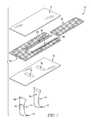
- FIG. 7is an exploded perspective view of the topper of FIGS. 4 and 5 showing that the topper includes a top layer made of fabric, a middle layer including two pieces of three-dimensional material, a bottom layer made of fabric, and two distribution sleeves made of fabric and configured to conduct air from the valve box under the inflatable bladders to one of the pieces of three-dimensional material; and
- FIG. 8is a perspective view of one of the pieces of three-dimensional material showing that the three-dimensional material provides air gaps through which air can flow to carry away heat and/or moisture from a patient's skin.
- a patient support apparatus 10illustratively includes a frame 12 , a patient support surface 14 (sometimes called surface 14 ) supported on the frame 12 , and an air box 16 as shown in FIG. 1 .
- the surface 14is adapted to support a patient lying on the patient support apparatus 10 and includes a topper 20 (shown in FIGS. 5-7 ) that extends along a top side 24 of the surface 14 .
- the topper 20is configured to conduct air along the top side 24 of the surface 14 adjacent to the interface of the surface 14 with a patient.
- the air conducted by the topper 20is pressurized and pushed through the topper 20 by the air box 16 .
- the topper 20cools and dries the patient's skin in order to reduce the risk of bed sore formation by the patient.
- the air box 16includes a user interface 40 shown in detail in FIG. 2 .
- the user interface 40includes a display screen 42 and a plurality of buttons 44 for inputting patient information and for controlling operation of the air box 16 and the surface 14 . More specifically, the user interface 40 includes a patient information input panel 45 , an alarm panel 46 , a lateral rotation therapy panel 47 , an inflation mode panel 48 , a normal inflation control panel 49 , and a microclimate control panel 50 .
- the microclimate control panel 50allows a user to adjust the flow of air provided by the air box 16 to the topper 20 and to adjust the temperature of air provided by the air box 16 to the topper 20 as suggested in FIG. 2 .
- a caregivercould increase flow of air from the air box 16 to the topper 20 by pressing an up evaporation (EVAP) arrow and could increase the temperature of air from the air box 16 to the topper by pressing an up temperature (TEMP) arrow.
- EVAPup evaporation
- TMPup temperature
- a preset level of flow and temperaturecould be selected by pressing a preset high, medium, or low button included in the microclimate control panel 50 .
- the temperature controlsmay be omitted.
- the illustrative topper 20is configured to receive air from the air box 16 and to conduct air pushed through the topper 20 by the air box 16 along an actively-cooled region 26 of the topper 20 as shown in FIG. 3 .
- the topper 20also allows natural air flow to occur in a passively-cooled region 28 of the topper 20 adjacent to the actively-cooled region 26 .
- the actively-cooled region 26is arranged to underlie a patient's pelvic region and torso region in order to reduce the risk of bed sore formation around a patient's pelvis (particularly under the sacrum) and around a patient's shoulders (particularly under the scapulae).
- air from the air box 16is introduced into the topper 20 at a first origination point 31 near a patient's pelvic region and at a second origination point 32 near a patient's shoulders.
- the airflows to exhaust through an outlet 33 positioned at the head end 35 of the topper 20 as shown in FIG. 4 .
- the airmay exhaust through an outlet 33 ′ positioned on a bottom side of the topper 20 as suggested in FIG. 4 .
- the illustrative topper 20allows for reduction of the pressure and flow needed from an air source (blower, compressor, etc) included in the air box 16 . Further, by directing the location of air introduction from the air box 16 under specific high-risk portions of a patient heat and moisture withdrawal from such areas may be comparable to other systems known in the art using a relatively small amount of air.
- a portion of the passively-cooled region 28is arranged to underlie a patient's legs and sometimes arms near a foot end 34 and lateral sides 36 , 38 of the surface 14 as shown in FIG. 3 .
- the passively-cooled region 28allows for natural air flow under a patient to be driven by temperature gradients across the topper 20 induced by the patient's body heat. Such natural air flow can provide heat and moisture withdrawal sufficient to reduce the risk of bed sores without air flow from the air box 16 .
- the patient support apparatus 10is shown diagrammatically to include the frame 12 , the surface 14 , and the air box 16 .
- the frame 12 alone, the surface 14 alone, a combination of the frame 12 and the air box 16 , or a combination of the surface 14 and the air box 16may provide a patient support apparatus as the term is applied herein.
- the frame 12illustratively includes a base 52 and a deck 54 .
- the base 52is configured to support the deck 54 , the surface 14 , and the air box 16 above a floor 11 .
- the deck 54underlies the surface 14 and is reconfigurable to adjust the position of the surface 14 when a patient is on the patient support apparatus 10 so that a patient can be supported while lying flat, sitting up in bed, or in a number of other positions.
- the air box 16may be integrated into the frame 12 or independently supported rather than being coupled to the frame 12 as in the illustrative embodiment.
- the surface 14includes (from bottom to top) a lower ticking 56 , a foam shell 58 , turn bladders 59 , a valve box 60 , an air manifold 62 , inflatable support bladders 65 , the topper 20 , and an upper ticking 69 as shown in FIGS. 5 and 6 .
- the lower ticking 56 and the upper ticking 69cooperate to encase the other components of the surface 14 as suggested in FIGS. 5 and 6 .
- the foam shell 58cooperates with the inflatable support bladders 65 to provide a cushion on which the patient is supported while positioned on the patient support apparatus 10 .
- the turn bladders 59are coupled to the air box 16 through the valve box 60 and may be inflated to rotate a patient about a longitudinal axis 14 A of the surface 14 as suggested in FIG. 6 .
- the valve box 60is pneumatically coupled to the topper 20 via the air manifold 62 and to the support bladders 64 , 66 , 68 to distribute air from the air box 16 around the surface 14 .
- the air manifold 62receives air from the air box 16 via the valve box 60 and delivers the air to the topper 20 near the origination points 31 , 32 as suggested in FIGS. 5 and 6 .
- the inflatable support bladders 65illustratively include head section bladders 64 , seat section bladders 66 , and foot section bladders 68 as shown in FIGS. 5 and 6 .
- Each section of bladders 64 , 66 , 68is inflatable to different pressures depending on pressure level selected on the user interface 40 for patient comfort.
- Each section of bladders 64 , 66 , 68may also be inflated or deflated to provide patient therapies or to reduce the risk of bed sores.
- the bladders 64 , 66 , and 68may be omitted and foam padding may replace one or more of the inflatable section bladders 64 , 66 , 68 .
- the topper 20illustratively includes a top layer 71 configured to underlie a patient on the patient support apparatus 10 , a bottom layer 73 spaced apart from the top layer 71 , a middle layer 72 arranged between the top layer 71 and the bottom layer 73 , and a pair of distribution sleeves 74 , 75 as shown in FIGS. 5-7 .
- the top layer 71 and the bottom layer 73are illustratively made from a vapor-permeable, liquid-impermeable fabric. More particularly, in the illustrative embodiment, the top layer 71 and the bottom layer 73 are made of urethane coated nylon available from Uretek of New Haven, Conn.
- the bottom layer 73may be made from vapor-impermeable, liquid-impermeable fabric.
- the middle layeris configured to provide an air gap between the top layer and the bottom layer 73 .
- the bottom layer 73is formed to include a first inlet port 41 and a second inlet port 43 each arranged under the actively-cooled region 26 and spaced apart from one another along a longitudinal axis A of the topper 20 as shown in FIG. 7 .
- the distribution sleeves 74 , 75are coupled to the bottom layer 73 and extend downwardly from the bottom layer 73 to connect the topper 20 to the manifold 62 as shown in FIG. 6 . Further, the distribution sleeve 74 extends between the foot section bladders 68 and the seat section bladders 66 , and the distribution sleeve 75 extends between the seat section bladders 66 and the head section bladders 64 as suggested in FIG. 6 .
- the distribution sleeves 74 , 75each include a flexible diffuser 76 and a fitting 78 as shown in FIGS. 5 and 6 .
- the flexible diffusers 76are illustratively made from the same fabric used in the top layer 71 and the bottom layer 73 of the topper 20 so that the distribution sleeves 74 , 75 do not cause discomfort for a patient laying on the surface 14 when the support bladders 65 are mostly deflated.
- Each flexible diffuser 76is configured to receive air from the manifold 62 and to deliver the air to the middle layer 72 of the topper 20 at the origination points 31 , 32 along the width of the actively-cooled region 26 of the topper 20 as suggested in FIGS. 5 and 6 .
- the fitting 78is configured to couple the flexible diffuser 76 to the manifold 62 and may be a quick-disconnect fitting.
- the middle layer 72 of the exemplary embodimentis configured to conduct air from the origination points 31 , 32 along the top surface 24 of the surface 14 and to separate the actively-cooled region 26 from the passively-cooled region 28 of the topper 20 as shown in FIGS. 6 and 7 .
- the middle layer 72illustratively includes a first piece of three-dimensional material 81 , a second piece of three-dimensional material 82 , and a divider 84 that pneumatically separates the first piece of three-dimensional material 81 from the second piece of three-dimensional material 82 .
- the first piece of three-dimensional material 81is illustratively arranged to lie under a patient's pelvic area and torso area as shown in FIGS. 6 and 7 .
- the first piece of three-dimensional material 81cooperates with the top layer 71 and the bottom layer 73 to define the actively-cooled region 26 of the topper 20 .
- the first piece of three-dimensional material 81is arranged to extend from the head end 35 of the topper 20 toward the foot end 34 of the topper 20 as shown in FIGS. 6 and 7 .
- the first piece of three-dimensional material 81is further spaced apart from the foot end 34 and from the lateral sides 36 , 38 of the topper 20 .
- the first piece of three-dimensional material 81is illustratively rectangular and is adjacent to the second piece of three-dimensional material 82 when viewed from above as shown in FIGS. 6 and 7 .
- the first piece of three-dimensional material 81may be located in other positions relative to a patient and/or may be broken into different portions to create multiple actively cooled regions of the topper 20 .
- the second piece of three-dimensional material 82is illustratively arranged to lie under a patient's legs and feet as shown in FIGS. 6 and 7 .
- the second piece of three-dimensional material 82cooperates with the top layer 71 and the bottom layer 73 of the topper 20 to define the passively-cooled region 28 of the topper 20 .
- the second piece of three-dimensional material 82is arranged to extend from the head end 35 to the foot end 34 of the topper 20 surrounding the first piece of three-dimensional material 81 so that the entire area of the topper 20 provides cooling for a patient's skin.
- the second piece of three-dimensional material 82is illustratively U-shaped when viewed from above and opens toward the head end 35 of the topper 20 as shown in FIGS. 6 and 7 .
- the second piece of material 82may be made from another material such as foam, fabric, padding, filler, or the like in order to maintain the thickness of the topper 20 without providing cooling outside the actively-cooled region 26 of the topper 20 .
- the divider 84includes three strips 86 , 87 , 88 as shown in FIG. 7 .
- the strip 88is part of the first distribution sleeve 74 as shown in FIG. 7 .
- the strips 86 , 87 , 88are each made of the same fabric used in the top layer 71 and the bottom layer 73 of the topper 20 but in other embodiments may be made from other fabrics or plastics.
- the strips 86 , 87 , 88are each sewn to the top layer 71 and the bottom layer 73 to create a barrier between the first piece of three-dimensional material 81 and the second layer of three-dimensional material 82 as shown in FIG. 6 .
- the strips 86 , 87 , 88may be adhered or welded to the top layer 71 and the bottom layer 73 in addition to and/or in place of sewing.
- the divider 84may be formed without the strips 86 , 87 , 88 by sewing the top layer 71 to the bottom layer 73 between the first and second pieces of three-dimensional material 81 , 82 .
- FIG. 8is a detail perspective view of a piece of the three-dimensional material used to create the first piece and the second piece of three-dimensional material 81 , 82 used in the middle layer 72 of the topper 20 .
- each piece of three-dimensional material 81 , 82is available under the trade name PRESSLESS® from Bodet & Horst GmbH & Co.
- other three-dimensional materialmay be used to provide an air gap between the top layer 71 and the bottom layer 73 of the topper 20 when a patient is lying on the topper 20 .
- the actively-cooled region 26may be arranged in other positions around the topper 20 , may have different total area or shape, and/or may be split into more than one area around the topper 20 .
- the actively-cooled region 26may be spaced apart from the head end 35 of the topper 20 and may be surrounded by the passively-cooled region 28 while still being arranged to underlie a patient's pelvic area and torso area.
- the actively-cooled region 26may be expanded toward the foot end 34 of the topper 20 to underlie a patient's feet in addition to her pelvic area and her torso area.
- the actively-cooled region 26may include a first area arranged to underlie a patient's pelvic area, a second area arranged to underlie a patient's torso area, and/or a third area arranged to underlie a patient's feet.
- the air box 16illustratively includes the user interface 40 , a controller 90 , a blower 96 , and a heater 98 .
- the controller 90is coupled for communication with the user interface 40 , the blower 96 , and the heater 98 as shown diagrammatically in FIG. 5 .
- the controller 90is also coupled for communication with the valve box 60 .
- the blower 96provides pressurized air for the inflatable bladders 59 , 65 and for the topper 20 .
- the heater 98is arranged inline with the blower 96 and is configured to warm air from the blower 96 before the air is delivered to the topper 20 .
- a cooler(not shown) or other air conditioning device(s) may also be included between the blower 96 and the topper 20 to prepare the air for use in therapeutic flow adjacent to a patient's skin.
- the heater 98may be replaced or augmented with optional heaters 97 , 99 situated in the manifold 62 and associated with the first and second origination points 31 , 32 , respectively, as shown in FIG. 5 .
- optional heaters 97 , 99allows for location-specific temperature control of therapeutic air applied adjacent to different portions of a patient while on the patient support apparatus 10 .
- the illustrative controller 90includes a memory 91 and a processor 93 as shown in FIG. 5 .
- the memory 91is configured to hold instructions and data for use by the processor 93 .
- the processor 93executes the instructions on the memory 91 and writes information to the memory 91 , for example, adjusting operation of the blower 96 and valve box 60 based on inputs received from the user interface 40 as proscribed by the instructions written in the memory 91 .
Landscapes
- Health & Medical Sciences (AREA)
- Nursing (AREA)
- Life Sciences & Earth Sciences (AREA)
- Animal Behavior & Ethology (AREA)
- General Health & Medical Sciences (AREA)
- Public Health (AREA)
- Veterinary Medicine (AREA)
- Invalid Beds And Related Equipment (AREA)
- Mattresses And Other Support Structures For Chairs And Beds (AREA)
Abstract
Description
Claims (20)
Priority Applications (1)
| Application Number | Priority Date | Filing Date | Title |
|---|---|---|---|
| US15/245,957US10426681B2 (en) | 2013-02-28 | 2016-08-24 | Topper for a patient surface with flexible fabric sleeves |
Applications Claiming Priority (3)
| Application Number | Priority Date | Filing Date | Title |
|---|---|---|---|
| US201361770704P | 2013-02-28 | 2013-02-28 | |
| US14/190,969US9433300B2 (en) | 2013-02-28 | 2014-02-26 | Topper for a patient surface |
| US15/245,957US10426681B2 (en) | 2013-02-28 | 2016-08-24 | Topper for a patient surface with flexible fabric sleeves |
Related Parent Applications (1)
| Application Number | Title | Priority Date | Filing Date |
|---|---|---|---|
| US14/190,969ContinuationUS9433300B2 (en) | 2013-02-28 | 2014-02-26 | Topper for a patient surface |
Publications (2)
| Publication Number | Publication Date |
|---|---|
| US20160361215A1 US20160361215A1 (en) | 2016-12-15 |
| US10426681B2true US10426681B2 (en) | 2019-10-01 |
Family
ID=50235928
Family Applications (2)
| Application Number | Title | Priority Date | Filing Date |
|---|---|---|---|
| US14/190,969ActiveUS9433300B2 (en) | 2013-02-28 | 2014-02-26 | Topper for a patient surface |
| US15/245,957Active2035-05-02US10426681B2 (en) | 2013-02-28 | 2016-08-24 | Topper for a patient surface with flexible fabric sleeves |
Family Applications Before (1)
| Application Number | Title | Priority Date | Filing Date |
|---|---|---|---|
| US14/190,969ActiveUS9433300B2 (en) | 2013-02-28 | 2014-02-26 | Topper for a patient surface |
Country Status (2)
| Country | Link |
|---|---|
| US (2) | US9433300B2 (en) |
| EP (1) | EP2772239B1 (en) |
Families Citing this family (33)
| Publication number | Priority date | Publication date | Assignee | Title |
|---|---|---|---|---|
| US9420895B2 (en)* | 2009-12-17 | 2016-08-23 | Stryker Corporation | Patient support |
| US9326616B2 (en)* | 2013-01-10 | 2016-05-03 | Dreamwell, Ltd. | Active airflow temperature controlled bedding systems |
| ES2659314T3 (en)* | 2015-02-09 | 2018-03-14 | Trafalgar Associates, LLC | Fire-resistant mattresses, fire-resistant mattress cover materials |
| US10489661B1 (en) | 2016-03-08 | 2019-11-26 | Ocuvera LLC | Medical environment monitoring system |
| US10600204B1 (en) | 2016-12-28 | 2020-03-24 | Ocuvera | Medical environment bedsore detection and prevention system |
| US10856668B2 (en)* | 2017-04-10 | 2020-12-08 | Hill-Rom Services, Inc. | Mattress overlay control system with rotary valves and graphical user interface for percussion and vibration, turn assist and microclimate management |
| US20190021926A1 (en)* | 2017-07-21 | 2019-01-24 | Hill-Rom Services, Inc. | Patient cooling system responsive to head elevation |
| US11173085B2 (en) | 2017-12-28 | 2021-11-16 | Stryker Corporation | Mattress cover for a mattress providing rotation therapy to a patient |
| US11246775B2 (en) | 2017-12-28 | 2022-02-15 | Stryker Corporation | Patient turning device for a patient support apparatus |
| AU2019201323B2 (en) | 2018-02-27 | 2020-03-05 | Hill-Rom Services, Inc. | Patient support surface control, end of life indication, and x-ray cassette sleeve |
| USD877915S1 (en) | 2018-09-28 | 2020-03-10 | Stryker Corporation | Crib assembly |
| USD888963S1 (en) | 2018-09-28 | 2020-06-30 | Stryker Corporation | Cover assembly for a patient support |
| USD879966S1 (en) | 2018-09-28 | 2020-03-31 | Stryker Corporation | Crib assembly |
| USD977109S1 (en) | 2018-09-28 | 2023-01-31 | Stryker Corporation | Crib assembly for a patient support |
| USD888964S1 (en) | 2018-09-28 | 2020-06-30 | Stryker Corporation | Crib assembly for a patient support |
| USD901940S1 (en) | 2018-09-28 | 2020-11-17 | Stryker Corporation | Patient support |
| USD888962S1 (en) | 2018-09-28 | 2020-06-30 | Stryker Corporation | Cover assembly for a patient support |
| USD894226S1 (en) | 2018-10-31 | 2020-08-25 | Stryker Corporation | Display screen or portion thereof with graphical user interface |
| USD890914S1 (en) | 2018-10-31 | 2020-07-21 | Stryker Corporation | Pump |
| USD894223S1 (en) | 2018-10-31 | 2020-08-25 | Stryker Corporation | Display screen with animated graphical user interface |
| USD894957S1 (en) | 2018-10-31 | 2020-09-01 | Stryker Corporation | Display screen or portion thereof with graphical user interface |
| USD892159S1 (en) | 2018-10-31 | 2020-08-04 | Stryker Corporation | Display screen with animated graphical user interface |
| USD893543S1 (en) | 2018-10-31 | 2020-08-18 | Stryker Corporation | Display screen with graphical user interface |
| USD894956S1 (en) | 2018-10-31 | 2020-09-01 | Stryker Corporation | Display screen or portion thereof with graphical user interface |
| US20200345160A1 (en)* | 2019-05-02 | 2020-11-05 | Juan Sebastian Iriarte Tineo | Systems and methods for sleeping bag with protective material |
| WO2020232161A1 (en) | 2019-05-14 | 2020-11-19 | Ige, Llc | Support system including layers of spacer fabric and non-viscoelastic pressure relief material, and method for measuring pressure and pressure distribution properties of a support system |
| US11712386B2 (en)* | 2019-07-15 | 2023-08-01 | Hill-Rom Services, Inc. | Pneumatic system blockage detection |
| US12042440B1 (en) | 2021-04-16 | 2024-07-23 | Turn Medical, LLC | Stowable patient supports |
| US12226356B1 (en) | 2021-04-16 | 2025-02-18 | Turn Medical, LLC | Adjustable posterior head support |
| US12121479B1 (en) | 2021-04-16 | 2024-10-22 | Turn Medical, LLC | Strap and release system |
| US20220330709A1 (en)* | 2021-04-16 | 2022-10-20 | Eshel Faraggi | Bedding vacuum pad |
| US12403057B1 (en) | 2021-04-16 | 2025-09-02 | Turn Medical, LLC | Proning face pack |
| US20250072637A1 (en)* | 2023-08-28 | 2025-03-06 | Riley Sylvestre | Multi-Chamber Adjustable Pillow |
Citations (84)
| Publication number | Priority date | Publication date | Assignee | Title |
|---|---|---|---|---|
| US3644950A (en) | 1969-08-01 | 1972-02-29 | Milton Roy Co | Patient support system |
| US3757366A (en) | 1971-08-18 | 1973-09-11 | W Sacher | Cushion for preventing and alleviating bedsores |
| US3778851A (en) | 1971-03-02 | 1973-12-18 | Haworth Air Conditioning Ltd | Mattress |
| US4225989A (en) | 1978-10-05 | 1980-10-07 | Glynwed Group Services Limited | Inflatable supports |
| US4267611A (en) | 1979-03-08 | 1981-05-19 | Arnold Agulnick | Inflatable massaging and cooling mattress |
| EP0046008A1 (en) | 1980-08-13 | 1982-02-17 | PAUL, Patrick Robin David | Mattress |
| US4347633A (en) | 1980-07-22 | 1982-09-07 | American Hospital Supply Corporation | Patient treating mattress |
| US4391009A (en) | 1980-10-17 | 1983-07-05 | Huntleigh Medical Ltd. | Ventilated body support |
| US4483030A (en) | 1982-05-03 | 1984-11-20 | Medisearch Pr, Inc. | Air pad |
| US4653130A (en) | 1984-11-26 | 1987-03-31 | Matsushita Electric Works, Ltd. | Bedsore preventing apparatus |
| US4862538A (en) | 1986-10-22 | 1989-09-05 | Span-America Medical Systems, Inc. | Multi-section mattress overlay for systematized pressure dispersion |
| US4944060A (en) | 1989-03-03 | 1990-07-31 | Peery John R | Mattress assembly for the prevention and treatment of decubitus ulcers |
| US4970743A (en) | 1990-01-29 | 1990-11-20 | Wride Larry N | Mattress and foundation system useable with water mattresses |
| US5010608A (en) | 1989-10-11 | 1991-04-30 | Du Pont Canada Inc. | Support system for reducing formation of decubitus ulcers |
| US5103519A (en) | 1988-05-09 | 1992-04-14 | Hasty Charles E | Air support bed with patient movement overlay |
| US5216768A (en) | 1988-11-17 | 1993-06-08 | Oliver H. Bodine, Jr. | Bed system |
| US5370439A (en) | 1994-01-04 | 1994-12-06 | Lowe; Warren | Vehicle seat ventilation |
| US5375273A (en) | 1992-10-29 | 1994-12-27 | Geomarine Systems, Inc. | Lateral rotation therapy mattress system and method |
| USD355488S (en) | 1993-12-13 | 1995-02-14 | Span-America Medical Systems, Inc. | Body aligner |
| US5473783A (en)* | 1994-04-04 | 1995-12-12 | Allen; Randall W. | Air percolating pad |
| US5487196A (en) | 1994-01-10 | 1996-01-30 | Span America Medical Systems, Inc. | Automated pressure relief mattress support system |
| US5493742A (en) | 1994-05-10 | 1996-02-27 | Lake Medical Products, Inc. | Ventilating air mattress with an inflating quilted pad |
| US5509155A (en) | 1994-08-04 | 1996-04-23 | Creative Medical, Inc. | Alternating low air loss pressure overlay for patient bedside chair |
| US5568660A (en) | 1992-06-24 | 1996-10-29 | Span-America Medical Systems, Inc. | Wheelchair cushion and cover |
| US5687438A (en) | 1994-08-04 | 1997-11-18 | Sentech Medical Systems, Inc. | Alternating low air loss pressure overlay for patient bedside chair and mobile wheel chair |
| US5715695A (en) | 1996-08-27 | 1998-02-10 | Lord; Kevin F. | Air conditioned seat |
| US5749109A (en)* | 1995-10-18 | 1998-05-12 | Mallinckrodt Medical, Inc. | Inflatable blanket having selective air flow patterns |
| US5755000A (en) | 1994-05-25 | 1998-05-26 | Egerton Hospital Equipment Limited | Low air-loss mattresses |
| US5797155A (en) | 1996-06-07 | 1998-08-25 | Span-America Medical Systems, Inc. | Wheelchair cushion with protectively encased self-adjusting reservoir means |
| US5870785A (en) | 1994-07-11 | 1999-02-16 | Hoorens; Jan | Mat, more specifically a mat for lying on |
| US5887304A (en) | 1997-07-10 | 1999-03-30 | Von Der Heyde; Christian P. | Apparatus and method for preventing sudden infant death syndrome |
| US5926884A (en) | 1997-08-05 | 1999-07-27 | Sentech Medical Systems, Inc. | Air distribution device for the prevention and the treatment of decubitus ulcers and pressure sores |
| US5987668A (en) | 1997-09-15 | 1999-11-23 | Span-America Medical Systems, Inc. | Fabric covered mattress pad |
| US6182315B1 (en) | 1998-12-30 | 2001-02-06 | Seven States Enterprise Co., Ltd. | Structure of three-layer venting mattress |
| US20020129449A1 (en)* | 2000-06-01 | 2002-09-19 | Crown Therapeutic, Inc. | Moisture drying mattress with separate zone controls |
| US20030019044A1 (en)* | 2000-03-09 | 2003-01-30 | Stefan Larsson | Bed |
| US20030050007A1 (en)* | 2001-09-13 | 2003-03-13 | Kevin Gebke | Pliable air duct with dust and condensation repellency |
| US6782574B2 (en) | 2000-07-18 | 2004-08-31 | Span-America Medical Systems, Inc. | Air-powered low interface pressure support surface |
| WO2006001980A2 (en) | 2004-06-02 | 2006-01-05 | Charles Arthur Lachenbruch | A non-powered heat wick for skin cooling |
| WO2006060796A2 (en) | 2004-12-02 | 2006-06-08 | Scott Technology Llc | Bolster system and method |
| US7191480B2 (en) | 1998-05-06 | 2007-03-20 | Hill-Rom Services, Inc. | Mattress or cushion structure |
| US7296314B2 (en) | 2006-01-04 | 2007-11-20 | Encompass Group, Llc | Patient support surface |
| AU2007249236A1 (en) | 2006-05-11 | 2007-11-22 | Arjo Ip Holding Ab | Multi-layered support system |
| US20080005843A1 (en) | 2004-04-30 | 2008-01-10 | Tactex Controls Inc. | Body Support Apparatus Having Automatic Pressure Control and Related Methods |
| EP1987806A2 (en) | 2007-04-30 | 2008-11-05 | Span-America Medical Systems, Inc. | Low Air Loss Moisture Control Mattress Overlay |
| US7469432B2 (en) | 2004-04-30 | 2008-12-30 | Hill-Rom Services, Inc. | Method and apparatus for improving air flow under a patient |
| US7469436B2 (en) | 2004-04-30 | 2008-12-30 | Hill-Rom Services, Inc. | Pressure relief surface |
| US7509698B2 (en) | 2005-08-10 | 2009-03-31 | Kreg Medical, Inc. | Therapeutic mattress |
| US20090217460A1 (en) | 2005-07-08 | 2009-09-03 | Bobey John A | Patient support |
| US7676862B2 (en) | 2004-09-13 | 2010-03-16 | Kreg Medical, Inc. | Siderail for hospital bed |
| US7698765B2 (en) | 2004-04-30 | 2010-04-20 | Hill-Rom Services, Inc. | Patient support |
| US7725963B2 (en) | 2002-11-12 | 2010-06-01 | Gray Tek, Inc. | Material mover having a fluid film reservoir |
| US20100132116A1 (en) | 2006-08-04 | 2010-06-03 | Stacy Richard B | Patient Support with Orientation Sensitive Air Bladder Control |
| US7743441B2 (en) | 2004-09-13 | 2010-06-29 | Kreg Therapeutics, Inc. | Expandable width bed |
| US7757318B2 (en) | 2004-09-13 | 2010-07-20 | Kreg Therapeutics, Inc. | Mattress for a hospital bed |
| US7779494B2 (en) | 2004-09-13 | 2010-08-24 | Kreg Therapeutics, Inc. | Bed having fixed length foot deck |
| US20100212089A1 (en) | 2007-10-02 | 2010-08-26 | Ryuji Kajiwara | Air mattress controller |
| US7849545B2 (en) | 2006-11-14 | 2010-12-14 | Hill-Rom Industries Sa | Control system for hospital bed mattress |
| US20110010855A1 (en)* | 2009-07-17 | 2011-01-20 | Dennis Flessate | Therapy and Low Air Loss Universal Coverlet |
| US20110047708A1 (en)* | 2009-09-02 | 2011-03-03 | Denver Mattress Co. Llc | Mattresses with heat dissipation |
| US20110061169A1 (en) | 2009-09-17 | 2011-03-17 | Caremed Supply, Inc. | Air mattress |
| US20110068939A1 (en) | 2009-09-18 | 2011-03-24 | Lachenbruch Charles A | Patient support surface index control |
| US20110107514A1 (en) | 2009-08-31 | 2011-05-12 | Amerigon Incorporated | Climate-controlled topper member for medical beds |
| US20110115635A1 (en)* | 2009-05-06 | 2011-05-19 | Dusko Petrovski | Control schemes and features for climate-controlled beds |
| US7954186B2 (en) | 2007-05-04 | 2011-06-07 | Gaymar Industries, Inc. | Inflatable mattress with uniform restraint |
| US7975335B2 (en)* | 2006-05-09 | 2011-07-12 | Hill-Rom Services, Inc. | Pulmonary mattress |
| US7975331B2 (en) | 2006-10-26 | 2011-07-12 | Hill-Rom Industries Sa | Device and method for controlling humidity at the surface of a supporting item of the mattress type |
| US20110247143A1 (en) | 2008-04-15 | 2011-10-13 | Richards Sandy M | Temperature and moisture regulating topper for non-powered person-support surfaces |
| US8037563B2 (en) | 2009-03-24 | 2011-10-18 | Hill-Rom Services, Inc. | Multiple air source mattress control system |
| US20110302719A1 (en) | 2010-06-12 | 2011-12-15 | American Home Health Care, Inc. | Patient support systems |
| US20120017376A1 (en) | 2008-12-22 | 2012-01-26 | Mikkelsen Tom D | Body support with fluid system and method of operating same |
| US8108957B2 (en) | 2007-05-31 | 2012-02-07 | Hill-Rom Services, Inc. | Pulmonary mattress |
| US8220090B2 (en) | 2006-10-26 | 2012-07-17 | Kap Medical | Multi-chamber air distribution support surface product and method |
| US8347436B2 (en) | 2007-10-31 | 2013-01-08 | Stryker Corporation | Adaptable mattress conversion |
| US8397327B2 (en) | 2010-08-31 | 2013-03-19 | Span-America Medical Systems, Inc. | Bed insert |
| US8402579B2 (en) | 2007-09-10 | 2013-03-26 | Gentherm Incorporated | Climate controlled beds and methods of operating the same |
| US20130074272A1 (en)* | 2011-09-23 | 2013-03-28 | Charles A. Lachenbruch | Moisture Management and Transport Cover |
| US8418286B2 (en) | 2008-07-18 | 2013-04-16 | Gentherm Incorporated | Climate controlled bed assembly |
| US20130205506A1 (en) | 2012-02-14 | 2013-08-15 | Charles A. Lachenbruch | Topper with Preferential Fluid Flow Distribution |
| US8719984B2 (en) | 2009-10-02 | 2014-05-13 | Sizewise Rentals, L.L.C. | Segmented air foam mattress |
| US8732874B2 (en) | 2006-10-13 | 2014-05-27 | Gentherm Incorporated | Heated and cooled bed assembly |
| US9009892B2 (en) | 2012-05-10 | 2015-04-21 | Hill-Rom Services, Inc. | Occupant support and topper assembly with liquid removal and microclimate control capabilities |
| US9125497B2 (en) | 2007-10-15 | 2015-09-08 | Gentherm Incorporated | Climate controlled bed assembly with intermediate layer |
| US9131781B2 (en)* | 2012-12-27 | 2015-09-15 | Select Comfort Corporation | Distribution pad for a temperature control system |
- 2014
- 2014-02-26USUS14/190,969patent/US9433300B2/enactiveActive
- 2014-02-27EPEP14156946.7Apatent/EP2772239B1/enactiveActive
- 2016
- 2016-08-24USUS15/245,957patent/US10426681B2/enactiveActive
Patent Citations (110)
| Publication number | Priority date | Publication date | Assignee | Title |
|---|---|---|---|---|
| US3644950A (en) | 1969-08-01 | 1972-02-29 | Milton Roy Co | Patient support system |
| US3778851A (en) | 1971-03-02 | 1973-12-18 | Haworth Air Conditioning Ltd | Mattress |
| US3757366A (en) | 1971-08-18 | 1973-09-11 | W Sacher | Cushion for preventing and alleviating bedsores |
| US4225989A (en) | 1978-10-05 | 1980-10-07 | Glynwed Group Services Limited | Inflatable supports |
| US4267611A (en) | 1979-03-08 | 1981-05-19 | Arnold Agulnick | Inflatable massaging and cooling mattress |
| US4347633A (en) | 1980-07-22 | 1982-09-07 | American Hospital Supply Corporation | Patient treating mattress |
| EP0046008A1 (en) | 1980-08-13 | 1982-02-17 | PAUL, Patrick Robin David | Mattress |
| US4391009A (en) | 1980-10-17 | 1983-07-05 | Huntleigh Medical Ltd. | Ventilated body support |
| US4483030A (en) | 1982-05-03 | 1984-11-20 | Medisearch Pr, Inc. | Air pad |
| US4653130A (en) | 1984-11-26 | 1987-03-31 | Matsushita Electric Works, Ltd. | Bedsore preventing apparatus |
| US4862538A (en) | 1986-10-22 | 1989-09-05 | Span-America Medical Systems, Inc. | Multi-section mattress overlay for systematized pressure dispersion |
| US5103519A (en) | 1988-05-09 | 1992-04-14 | Hasty Charles E | Air support bed with patient movement overlay |
| US5216768A (en) | 1988-11-17 | 1993-06-08 | Oliver H. Bodine, Jr. | Bed system |
| US4944060A (en) | 1989-03-03 | 1990-07-31 | Peery John R | Mattress assembly for the prevention and treatment of decubitus ulcers |
| US5010608A (en) | 1989-10-11 | 1991-04-30 | Du Pont Canada Inc. | Support system for reducing formation of decubitus ulcers |
| US4970743A (en) | 1990-01-29 | 1990-11-20 | Wride Larry N | Mattress and foundation system useable with water mattresses |
| US5568660A (en) | 1992-06-24 | 1996-10-29 | Span-America Medical Systems, Inc. | Wheelchair cushion and cover |
| US5375273A (en) | 1992-10-29 | 1994-12-27 | Geomarine Systems, Inc. | Lateral rotation therapy mattress system and method |
| USD355488S (en) | 1993-12-13 | 1995-02-14 | Span-America Medical Systems, Inc. | Body aligner |
| US5370439A (en) | 1994-01-04 | 1994-12-06 | Lowe; Warren | Vehicle seat ventilation |
| US5487196A (en) | 1994-01-10 | 1996-01-30 | Span America Medical Systems, Inc. | Automated pressure relief mattress support system |
| US5473783A (en)* | 1994-04-04 | 1995-12-12 | Allen; Randall W. | Air percolating pad |
| US5493742A (en) | 1994-05-10 | 1996-02-27 | Lake Medical Products, Inc. | Ventilating air mattress with an inflating quilted pad |
| US5755000A (en) | 1994-05-25 | 1998-05-26 | Egerton Hospital Equipment Limited | Low air-loss mattresses |
| US5870785A (en) | 1994-07-11 | 1999-02-16 | Hoorens; Jan | Mat, more specifically a mat for lying on |
| US5509155A (en) | 1994-08-04 | 1996-04-23 | Creative Medical, Inc. | Alternating low air loss pressure overlay for patient bedside chair |
| US5687438A (en) | 1994-08-04 | 1997-11-18 | Sentech Medical Systems, Inc. | Alternating low air loss pressure overlay for patient bedside chair and mobile wheel chair |
| US5749109A (en)* | 1995-10-18 | 1998-05-12 | Mallinckrodt Medical, Inc. | Inflatable blanket having selective air flow patterns |
| US5797155A (en) | 1996-06-07 | 1998-08-25 | Span-America Medical Systems, Inc. | Wheelchair cushion with protectively encased self-adjusting reservoir means |
| US5715695A (en) | 1996-08-27 | 1998-02-10 | Lord; Kevin F. | Air conditioned seat |
| US5887304A (en) | 1997-07-10 | 1999-03-30 | Von Der Heyde; Christian P. | Apparatus and method for preventing sudden infant death syndrome |
| US5926884A (en) | 1997-08-05 | 1999-07-27 | Sentech Medical Systems, Inc. | Air distribution device for the prevention and the treatment of decubitus ulcers and pressure sores |
| US5987668A (en) | 1997-09-15 | 1999-11-23 | Span-America Medical Systems, Inc. | Fabric covered mattress pad |
| US8601620B2 (en) | 1998-05-06 | 2013-12-10 | Hill-Rom Services, Inc. | Cover system for a patient support surface |
| US7966680B2 (en) | 1998-05-06 | 2011-06-28 | Hill-Rom Services, Inc. | Patient support surface |
| US7191480B2 (en) | 1998-05-06 | 2007-03-20 | Hill-Rom Services, Inc. | Mattress or cushion structure |
| US7617555B2 (en) | 1998-05-06 | 2009-11-17 | Hill-Rom Services, Inc. | Patient support surface |
| US6182315B1 (en) | 1998-12-30 | 2001-02-06 | Seven States Enterprise Co., Ltd. | Structure of three-layer venting mattress |
| US20030019044A1 (en)* | 2000-03-09 | 2003-01-30 | Stefan Larsson | Bed |
| US20020129449A1 (en)* | 2000-06-01 | 2002-09-19 | Crown Therapeutic, Inc. | Moisture drying mattress with separate zone controls |
| US6782574B2 (en) | 2000-07-18 | 2004-08-31 | Span-America Medical Systems, Inc. | Air-powered low interface pressure support surface |
| US7296315B2 (en) | 2000-07-18 | 2007-11-20 | Span-America Medical Systems, Inc. | Air-powered low interface pressure support surface |
| US20030050007A1 (en)* | 2001-09-13 | 2003-03-13 | Kevin Gebke | Pliable air duct with dust and condensation repellency |
| US7725963B2 (en) | 2002-11-12 | 2010-06-01 | Gray Tek, Inc. | Material mover having a fluid film reservoir |
| US7698765B2 (en) | 2004-04-30 | 2010-04-20 | Hill-Rom Services, Inc. | Patient support |
| US20080005843A1 (en) | 2004-04-30 | 2008-01-10 | Tactex Controls Inc. | Body Support Apparatus Having Automatic Pressure Control and Related Methods |
| US7469432B2 (en) | 2004-04-30 | 2008-12-30 | Hill-Rom Services, Inc. | Method and apparatus for improving air flow under a patient |
| US7469436B2 (en) | 2004-04-30 | 2008-12-30 | Hill-Rom Services, Inc. | Pressure relief surface |
| US8146191B2 (en) | 2004-04-30 | 2012-04-03 | Hill-Rom Services, Inc. | Patient support |
| US8196240B2 (en) | 2004-04-30 | 2012-06-12 | Hill-Rom Services, Inc. | Pressure relief surface |
| US7937791B2 (en) | 2004-04-30 | 2011-05-10 | Hill-Rom Services, Inc. | Pressure relief surface |
| WO2006001980A2 (en) | 2004-06-02 | 2006-01-05 | Charles Arthur Lachenbruch | A non-powered heat wick for skin cooling |
| US8056160B2 (en) | 2004-09-13 | 2011-11-15 | Kreg Medical, Inc. | Siderail for hospital bed |
| US8069514B2 (en) | 2004-09-13 | 2011-12-06 | Kreg Medical, Inc. | Expandable width bed |
| US7676862B2 (en) | 2004-09-13 | 2010-03-16 | Kreg Medical, Inc. | Siderail for hospital bed |
| US7757318B2 (en) | 2004-09-13 | 2010-07-20 | Kreg Therapeutics, Inc. | Mattress for a hospital bed |
| US7779494B2 (en) | 2004-09-13 | 2010-08-24 | Kreg Therapeutics, Inc. | Bed having fixed length foot deck |
| US7743441B2 (en) | 2004-09-13 | 2010-06-29 | Kreg Therapeutics, Inc. | Expandable width bed |
| US20090106907A1 (en) | 2004-10-06 | 2009-04-30 | Chambers Kenith W | Method and Apparatus For Improving Air Flow Under A Patient |
| US7712164B2 (en) | 2004-10-06 | 2010-05-11 | Hill-Rom Services, Inc. | Method and apparatus for improving air flow under a patient |
| WO2006060796A2 (en) | 2004-12-02 | 2006-06-08 | Scott Technology Llc | Bolster system and method |
| US20090217460A1 (en) | 2005-07-08 | 2009-09-03 | Bobey John A | Patient support |
| US7716766B2 (en) | 2005-08-10 | 2010-05-18 | Kreg Medical, Inc. | Therapeutic mattress |
| US7587776B2 (en) | 2005-08-10 | 2009-09-15 | Kreg Medical, Inc. | Dynamic therapy bed system |
| US7536739B2 (en) | 2005-08-10 | 2009-05-26 | Kreg Medical, Inc. | Therapeutic mattress |
| US7509698B2 (en) | 2005-08-10 | 2009-03-31 | Kreg Medical, Inc. | Therapeutic mattress |
| US7296314B2 (en) | 2006-01-04 | 2007-11-20 | Encompass Group, Llc | Patient support surface |
| US7975335B2 (en)* | 2006-05-09 | 2011-07-12 | Hill-Rom Services, Inc. | Pulmonary mattress |
| US8474074B2 (en) | 2006-05-09 | 2013-07-02 | Hill-Rom Services, Inc. | Pulmonary mattress |
| US8372182B2 (en) | 2006-05-11 | 2013-02-12 | Huntleigh Technology Limited | Multi-layered support system |
| US7914611B2 (en) | 2006-05-11 | 2011-03-29 | Kci Licensing, Inc. | Multi-layered support system |
| US8118920B2 (en) | 2006-05-11 | 2012-02-21 | Kci Licensing, Inc. | Multi-layered support system |
| AU2007249236B2 (en) | 2006-05-11 | 2011-08-25 | Arjo Ip Holding Ab | Multi-layered support system |
| AU2007249236A1 (en) | 2006-05-11 | 2007-11-22 | Arjo Ip Holding Ab | Multi-layered support system |
| US20100132116A1 (en) | 2006-08-04 | 2010-06-03 | Stacy Richard B | Patient Support with Orientation Sensitive Air Bladder Control |
| US8732874B2 (en) | 2006-10-13 | 2014-05-27 | Gentherm Incorporated | Heated and cooled bed assembly |
| US7975331B2 (en) | 2006-10-26 | 2011-07-12 | Hill-Rom Industries Sa | Device and method for controlling humidity at the surface of a supporting item of the mattress type |
| US8220090B2 (en) | 2006-10-26 | 2012-07-17 | Kap Medical | Multi-chamber air distribution support surface product and method |
| US7849545B2 (en) | 2006-11-14 | 2010-12-14 | Hill-Rom Industries Sa | Control system for hospital bed mattress |
| EP1987806A2 (en) | 2007-04-30 | 2008-11-05 | Span-America Medical Systems, Inc. | Low Air Loss Moisture Control Mattress Overlay |
| EP1987806B1 (en) | 2007-04-30 | 2012-03-21 | Span-America Medical Systems, Inc. | Low air loss moisture control mattress overlay |
| US7954186B2 (en) | 2007-05-04 | 2011-06-07 | Gaymar Industries, Inc. | Inflatable mattress with uniform restraint |
| US8108957B2 (en) | 2007-05-31 | 2012-02-07 | Hill-Rom Services, Inc. | Pulmonary mattress |
| US8584279B2 (en) | 2007-05-31 | 2013-11-19 | Hill-Rom Services, Inc. | Pulmonary mattress |
| US8402579B2 (en) | 2007-09-10 | 2013-03-26 | Gentherm Incorporated | Climate controlled beds and methods of operating the same |
| US20100212089A1 (en) | 2007-10-02 | 2010-08-26 | Ryuji Kajiwara | Air mattress controller |
| US9125497B2 (en) | 2007-10-15 | 2015-09-08 | Gentherm Incorporated | Climate controlled bed assembly with intermediate layer |
| US8347436B2 (en) | 2007-10-31 | 2013-01-08 | Stryker Corporation | Adaptable mattress conversion |
| US20110247143A1 (en) | 2008-04-15 | 2011-10-13 | Richards Sandy M | Temperature and moisture regulating topper for non-powered person-support surfaces |
| US8418286B2 (en) | 2008-07-18 | 2013-04-16 | Gentherm Incorporated | Climate controlled bed assembly |
| US20120017376A1 (en) | 2008-12-22 | 2012-01-26 | Mikkelsen Tom D | Body support with fluid system and method of operating same |
| US8037563B2 (en) | 2009-03-24 | 2011-10-18 | Hill-Rom Services, Inc. | Multiple air source mattress control system |
| US20110115635A1 (en)* | 2009-05-06 | 2011-05-19 | Dusko Petrovski | Control schemes and features for climate-controlled beds |
| US20110010855A1 (en)* | 2009-07-17 | 2011-01-20 | Dennis Flessate | Therapy and Low Air Loss Universal Coverlet |
| US8332975B2 (en) | 2009-08-31 | 2012-12-18 | Gentherm Incorporated | Climate-controlled topper member for medical beds |
| US8191187B2 (en) | 2009-08-31 | 2012-06-05 | Amerigon Incorporated | Environmentally-conditioned topper member for beds |
| US20110258778A1 (en) | 2009-08-31 | 2011-10-27 | Amerigon Incorporated | Environmentally-conditioned topper member for beds |
| US20110107514A1 (en) | 2009-08-31 | 2011-05-12 | Amerigon Incorporated | Climate-controlled topper member for medical beds |
| US8621687B2 (en) | 2009-08-31 | 2014-01-07 | Gentherm Incorporated | Topper member for bed |
| US20110047708A1 (en)* | 2009-09-02 | 2011-03-03 | Denver Mattress Co. Llc | Mattresses with heat dissipation |
| US20110061169A1 (en) | 2009-09-17 | 2011-03-17 | Caremed Supply, Inc. | Air mattress |
| US8156589B2 (en) | 2009-09-17 | 2012-04-17 | Caremed Supply, Inc. | Air mattress |
| US20110068939A1 (en) | 2009-09-18 | 2011-03-24 | Lachenbruch Charles A | Patient support surface index control |
| US8719984B2 (en) | 2009-10-02 | 2014-05-13 | Sizewise Rentals, L.L.C. | Segmented air foam mattress |
| US20110302719A1 (en) | 2010-06-12 | 2011-12-15 | American Home Health Care, Inc. | Patient support systems |
| US8397327B2 (en) | 2010-08-31 | 2013-03-19 | Span-America Medical Systems, Inc. | Bed insert |
| US20130074272A1 (en)* | 2011-09-23 | 2013-03-28 | Charles A. Lachenbruch | Moisture Management and Transport Cover |
| US20130205506A1 (en) | 2012-02-14 | 2013-08-15 | Charles A. Lachenbruch | Topper with Preferential Fluid Flow Distribution |
| US9009892B2 (en) | 2012-05-10 | 2015-04-21 | Hill-Rom Services, Inc. | Occupant support and topper assembly with liquid removal and microclimate control capabilities |
| US9131781B2 (en)* | 2012-12-27 | 2015-09-15 | Select Comfort Corporation | Distribution pad for a temperature control system |
Non-Patent Citations (1)
| Title |
|---|
| Search Report and Written Opinion from the European Patent Office for Application No. 14156946.7-1651, completed Jun. 25, 2014, 6 pages. |
Also Published As
| Publication number | Publication date |
|---|---|
| US20140237726A1 (en) | 2014-08-28 |
| US20160361215A1 (en) | 2016-12-15 |
| US9433300B2 (en) | 2016-09-06 |
| EP2772239A1 (en) | 2014-09-03 |
| EP2772239B1 (en) | 2017-07-12 |
Similar Documents
| Publication | Publication Date | Title |
|---|---|---|
| US10426681B2 (en) | Topper for a patient surface with flexible fabric sleeves | |
| US11684529B2 (en) | Mattress cover sensor method | |
| US10265231B2 (en) | Self-powered microclimate controlled mattress | |
| US10507147B2 (en) | Patient support | |
| US8555440B2 (en) | Patient lifter with intra operative controlled temperature air delivery system | |
| US20200268163A1 (en) | Mattress with valve system | |
| US8745784B2 (en) | Mattress system | |
| US9750655B2 (en) | Conformable support system | |
| US10092470B2 (en) | Patient lifter with intraoperative controlled temperature air delivery system | |
| US20140007353A1 (en) | Patient turner | |
| US7155766B1 (en) | Bolster system and method | |
| EP0821928A2 (en) | Surface pad system for a surgical table | |
| US20120079656A1 (en) | Patient lifter with intraoperative controlled temperature air delivery system | |
| EP3431066B1 (en) | Patient cooling system responsive to head elevation | |
| KR100904625B1 (en) | Drying device for bedsore prevention mattress | |
| EP3649898A1 (en) | Temperature and moisture regulating topper for non-powered person-support surfaces |
Legal Events
| Date | Code | Title | Description |
|---|---|---|---|
| AS | Assignment | Owner name:JPMORGAN CHASE BANK, N.A., AS COLLATERAL AGENT, ILLINOIS Free format text:SECURITY AGREEMENT;ASSIGNORS:HILL-ROM SERVICES, INC.;ASPEN SURGICAL PRODUCTS, INC.;ALLEN MEDICAL SYSTEMS, INC.;AND OTHERS;REEL/FRAME:040145/0445 Effective date:20160921 Owner name:JPMORGAN CHASE BANK, N.A., AS COLLATERAL AGENT, IL Free format text:SECURITY AGREEMENT;ASSIGNORS:HILL-ROM SERVICES, INC.;ASPEN SURGICAL PRODUCTS, INC.;ALLEN MEDICAL SYSTEMS, INC.;AND OTHERS;REEL/FRAME:040145/0445 Effective date:20160921 | |
| STPP | Information on status: patent application and granting procedure in general | Free format text:NON FINAL ACTION MAILED | |
| AS | Assignment | Owner name:HILL-ROM SERVICES, INC., INDIANA Free format text:ASSIGNMENT OF ASSIGNORS INTEREST;ASSIGNORS:GIBSON, LUKE;WILLIAMS, JOSHUA A.;WILLIAMSON, RACHEL L.;AND OTHERS;SIGNING DATES FROM 20140306 TO 20140313;REEL/FRAME:048717/0239 | |
| STPP | Information on status: patent application and granting procedure in general | Free format text:RESPONSE TO NON-FINAL OFFICE ACTION ENTERED AND FORWARDED TO EXAMINER | |
| STPP | Information on status: patent application and granting procedure in general | Free format text:NOTICE OF ALLOWANCE MAILED -- APPLICATION RECEIVED IN OFFICE OF PUBLICATIONS | |
| STPP | Information on status: patent application and granting procedure in general | Free format text:PUBLICATIONS -- ISSUE FEE PAYMENT VERIFIED | |
| AS | Assignment | Owner name:ALLEN MEDICAL SYSTEMS, INC., ILLINOIS Free format text:RELEASE BY SECURED PARTY;ASSIGNOR:JPMORGAN CHASE BANK, N.A.;REEL/FRAME:050254/0513 Effective date:20190830 Owner name:HILL-ROM, INC., ILLINOIS Free format text:RELEASE BY SECURED PARTY;ASSIGNOR:JPMORGAN CHASE BANK, N.A.;REEL/FRAME:050254/0513 Effective date:20190830 Owner name:VOALTE, INC., FLORIDA Free format text:RELEASE BY SECURED PARTY;ASSIGNOR:JPMORGAN CHASE BANK, N.A.;REEL/FRAME:050254/0513 Effective date:20190830 Owner name:HILL-ROM SERVICES, INC., ILLINOIS Free format text:RELEASE BY SECURED PARTY;ASSIGNOR:JPMORGAN CHASE BANK, N.A.;REEL/FRAME:050254/0513 Effective date:20190830 Owner name:MORTARA INSTRUMENT SERVICES, INC., WISCONSIN Free format text:RELEASE BY SECURED PARTY;ASSIGNOR:JPMORGAN CHASE BANK, N.A.;REEL/FRAME:050254/0513 Effective date:20190830 Owner name:WELCH ALLYN, INC., NEW YORK Free format text:RELEASE BY SECURED PARTY;ASSIGNOR:JPMORGAN CHASE BANK, N.A.;REEL/FRAME:050254/0513 Effective date:20190830 Owner name:ANODYNE MEDICAL DEVICE, INC., FLORIDA Free format text:RELEASE BY SECURED PARTY;ASSIGNOR:JPMORGAN CHASE BANK, N.A.;REEL/FRAME:050254/0513 Effective date:20190830 Owner name:MORTARA INSTRUMENT, INC., WISCONSIN Free format text:RELEASE BY SECURED PARTY;ASSIGNOR:JPMORGAN CHASE BANK, N.A.;REEL/FRAME:050254/0513 Effective date:20190830 Owner name:HILL-ROM COMPANY, INC., ILLINOIS Free format text:RELEASE BY SECURED PARTY;ASSIGNOR:JPMORGAN CHASE BANK, N.A.;REEL/FRAME:050254/0513 Effective date:20190830 | |
| AS | Assignment | Owner name:JPMORGAN CHASE BANK, N.A., ILLINOIS Free format text:SECURITY AGREEMENT;ASSIGNORS:HILL-ROM HOLDINGS, INC.;HILL-ROM, INC.;HILL-ROM SERVICES, INC.;AND OTHERS;REEL/FRAME:050260/0644 Effective date:20190830 | |
| STCF | Information on status: patent grant | Free format text:PATENTED CASE | |
| AS | Assignment | Owner name:HILL-ROM HOLDINGS, INC., ILLINOIS Free format text:RELEASE OF SECURITY INTEREST AT REEL/FRAME 050260/0644;ASSIGNOR:JPMORGAN CHASE BANK, N.A.;REEL/FRAME:058517/0001 Effective date:20211213 Owner name:BARDY DIAGNOSTICS, INC., ILLINOIS Free format text:RELEASE OF SECURITY INTEREST AT REEL/FRAME 050260/0644;ASSIGNOR:JPMORGAN CHASE BANK, N.A.;REEL/FRAME:058517/0001 Effective date:20211213 Owner name:VOALTE, INC., FLORIDA Free format text:RELEASE OF SECURITY INTEREST AT REEL/FRAME 050260/0644;ASSIGNOR:JPMORGAN CHASE BANK, N.A.;REEL/FRAME:058517/0001 Effective date:20211213 Owner name:HILL-ROM, INC., ILLINOIS Free format text:RELEASE OF SECURITY INTEREST AT REEL/FRAME 050260/0644;ASSIGNOR:JPMORGAN CHASE BANK, N.A.;REEL/FRAME:058517/0001 Effective date:20211213 Owner name:WELCH ALLYN, INC., NEW YORK Free format text:RELEASE OF SECURITY INTEREST AT REEL/FRAME 050260/0644;ASSIGNOR:JPMORGAN CHASE BANK, N.A.;REEL/FRAME:058517/0001 Effective date:20211213 Owner name:ALLEN MEDICAL SYSTEMS, INC., ILLINOIS Free format text:RELEASE OF SECURITY INTEREST AT REEL/FRAME 050260/0644;ASSIGNOR:JPMORGAN CHASE BANK, N.A.;REEL/FRAME:058517/0001 Effective date:20211213 Owner name:HILL-ROM SERVICES, INC., ILLINOIS Free format text:RELEASE OF SECURITY INTEREST AT REEL/FRAME 050260/0644;ASSIGNOR:JPMORGAN CHASE BANK, N.A.;REEL/FRAME:058517/0001 Effective date:20211213 Owner name:BREATHE TECHNOLOGIES, INC., CALIFORNIA Free format text:RELEASE OF SECURITY INTEREST AT REEL/FRAME 050260/0644;ASSIGNOR:JPMORGAN CHASE BANK, N.A.;REEL/FRAME:058517/0001 Effective date:20211213 | |
| MAFP | Maintenance fee payment | Free format text:PAYMENT OF MAINTENANCE FEE, 4TH YEAR, LARGE ENTITY (ORIGINAL EVENT CODE: M1551); ENTITY STATUS OF PATENT OWNER: LARGE ENTITY Year of fee payment:4 |