US10426680B2 - Air bladder control of mattress/frame width expansion - Google Patents
Air bladder control of mattress/frame width expansionDownload PDFInfo
- Publication number
- US10426680B2 US10426680B2US15/214,530US201615214530AUS10426680B2US 10426680 B2US10426680 B2US 10426680B2US 201615214530 AUS201615214530 AUS 201615214530AUS 10426680 B2US10426680 B2US 10426680B2
- Authority
- US
- United States
- Prior art keywords
- extension
- patient support
- chambers
- extension chambers
- side deck
- Prior art date
- Legal status (The legal status is an assumption and is not a legal conclusion. Google has not performed a legal analysis and makes no representation as to the accuracy of the status listed.)
- Active, expires
Links
- 210000004712air sacAnatomy0.000title1
- 239000012530fluidSubstances0.000claimsdescription79
- 239000006260foamSubstances0.000claimsdescription14
- 238000012546transferMethods0.000claimsdescription6
- 238000004891communicationMethods0.000description13
- 230000005540biological transmissionEffects0.000description2
- 238000010586diagramMethods0.000description2
- 230000006870functionEffects0.000description2
- 238000012986modificationMethods0.000description2
- 230000004048modificationEffects0.000description2
- 238000013519translationMethods0.000description2
- 230000004308accommodationEffects0.000description1
- 238000007792additionMethods0.000description1
- 230000007423decreaseEffects0.000description1
- 238000005259measurementMethods0.000description1
- 238000000034methodMethods0.000description1
- 230000002441reversible effectEffects0.000description1
- 238000005096rolling processMethods0.000description1
Images


Classifications
- A—HUMAN NECESSITIES
- A61—MEDICAL OR VETERINARY SCIENCE; HYGIENE
- A61G—TRANSPORT, PERSONAL CONVEYANCES, OR ACCOMMODATION SPECIALLY ADAPTED FOR PATIENTS OR DISABLED PERSONS; OPERATING TABLES OR CHAIRS; CHAIRS FOR DENTISTRY; FUNERAL DEVICES
- A61G7/00—Beds specially adapted for nursing; Devices for lifting patients or disabled persons
- A61G7/002—Beds specially adapted for nursing; Devices for lifting patients or disabled persons having adjustable mattress frame
- A61G7/018—Control or drive mechanisms
- A—HUMAN NECESSITIES
- A61—MEDICAL OR VETERINARY SCIENCE; HYGIENE
- A61G—TRANSPORT, PERSONAL CONVEYANCES, OR ACCOMMODATION SPECIALLY ADAPTED FOR PATIENTS OR DISABLED PERSONS; OPERATING TABLES OR CHAIRS; CHAIRS FOR DENTISTRY; FUNERAL DEVICES
- A61G7/00—Beds specially adapted for nursing; Devices for lifting patients or disabled persons
- A61G7/05—Parts, details or accessories of beds
- A61G7/0507—Side-rails
- A—HUMAN NECESSITIES
- A61—MEDICAL OR VETERINARY SCIENCE; HYGIENE
- A61G—TRANSPORT, PERSONAL CONVEYANCES, OR ACCOMMODATION SPECIALLY ADAPTED FOR PATIENTS OR DISABLED PERSONS; OPERATING TABLES OR CHAIRS; CHAIRS FOR DENTISTRY; FUNERAL DEVICES
- A61G7/00—Beds specially adapted for nursing; Devices for lifting patients or disabled persons
- A61G7/05—Parts, details or accessories of beds
- A61G7/0525—Side-bolsters
- A—HUMAN NECESSITIES
- A61—MEDICAL OR VETERINARY SCIENCE; HYGIENE
- A61G—TRANSPORT, PERSONAL CONVEYANCES, OR ACCOMMODATION SPECIALLY ADAPTED FOR PATIENTS OR DISABLED PERSONS; OPERATING TABLES OR CHAIRS; CHAIRS FOR DENTISTRY; FUNERAL DEVICES
- A61G7/00—Beds specially adapted for nursing; Devices for lifting patients or disabled persons
- A61G7/05—Parts, details or accessories of beds
- A61G7/057—Arrangements for preventing bed-sores or for supporting patients with burns, e.g. mattresses specially adapted therefor
- A61G7/05769—Arrangements for preventing bed-sores or for supporting patients with burns, e.g. mattresses specially adapted therefor with inflatable chambers
- A61G7/05776—Arrangements for preventing bed-sores or for supporting patients with burns, e.g. mattresses specially adapted therefor with inflatable chambers with at least two groups of alternately inflated chambers
Definitions
- the present disclosurerelates to patient support systems. Specifically, the present disclosure relates to patient support systems which include patient support devices that can be adjusted in width to provide extended patient support surfaces.
- Patient support devicessuch as hospital beds
- the bedscan be equipped for width-retraction.
- a patient support system for supporting a patientincludes a bed including a deck and extension chambers.
- the deckhas a main deck portion and side deck portions connected to the main deck portion at opposing longitudinal sides of the main deck portion.
- the bedincludes a controller configured to send a command signal indicative of a command for supply of fluid to the extension chambers.
- the bedincludes a fluid supply device configured to receive the command signal to supply fluid to the extension chambers.
- the extension chambersare configured to receive fluid from the fluid supply device to drive the side deck portions between a retracted position and an extended position, and are configured to support the patient.
- the side deck portionsare slidingly connected to the main deck portion.
- each side deck portionsis connected to the main deck portion by an extension track for translating the side deck portions between the retracted and extended positions.
- each extension trackincludes a lock configured to selectively engage the side deck portions with the main deck to prevent movement therebetween.
- the bedincludes a mattress and the extension chambers are formed as portions of the mattress.
- the mattressdefines a patient support surface of the bed and the extension chambers are configured to provide an additional patient support surface upon extension of the side deck portions from the main deck portion, the patient support surface and the additional patient support surface together define an extended patient support surface.
- each of the extensions chambersis connected to a respective one of the side deck portions such that upon inflation of one of the extension chambers the respective side deck portion is driven outwardly from the main deck portion.
- each side deck portionincludes an outward end, and each of the extension chambers is positioned between a mattress of the bed and the outward end of the respective side deck portion.
- the bedincludes a mattress and the extension chambers each form a portion of the mattress, wherein the bed includes a foam bolster positioned between each extension chamber and a mattress center portion, and another foam bolster positioned on an outward end of each extension chamber.
- the bedincludes elastic bands encircling the foam bolsters to sandwich the extension chambers therebetween so as to provide a compressive exhaust force for deflation of the extension chambers.
- each extension chamberis connected to its respective side deck portion by fastening of the extension chamber to the side deck portion.
- the fasteningis by snap-connection.
- each extension chamberis connected to a top side of its respective side deck portion.
- each extension chamberis connected to its respective side deck portion by connection with a flange extending perpendicularly from the respective side deck portion.
- the extension chamberscomprise a drive mechanism configured to extend and retract the side deck portions.
- the bedcomprises no other drive mechanism capable of extension of the side deck portions.
- a patient support system for supporting a patientincludes a bed including a deck and extension chambers, the deck having a main deck portion and side deck portions connected to the main deck portion at opposing longitudinal sides of the main deck portion, a controller configured to receive a user input indicating a desired position of the side deck portions between a retracted and an extended position, to determine a pressurization level required for the extension chambers to achieve the desire position, and to send a command signal indicating a requirement for transfer of fluid to or from the extension chambers, a fluid supply device configured to receive the command signal.
- the extension chambersare configured to receive fluid from the fluid supply device to drive the side deck portions between the retracted position and the extended position, and are configured to support the patient.
- a method of operating a patient support systemincludes receiving an input indicating a desired bed width, determining a required state of inflatable extension chambers required to achieve the desired bed width, and operating a fluid supply system to pressurize the extension chambers to achieve the required state.
- determining the required statecomprises determining a current bed width. In some embodiments, determining the required state comprises determining a current pressurization level of the extension chambers.
- FIG. 1Ais a perspective view of a patient support system including a bed having a frame, a deck, and a mattress including extension chambers, the bed being configured such that the extension chambers are in a deflated mode and side deck portions are in a retracted position;
- FIG. 1Bis a perspective view of a patient support system of FIG. 1A with the bed being configured such that the extension chambers are in an inflated mode and side deck portions are in an extended position;
- FIG. 2Ais a perspective partially exploded view of the patient support system of FIG. 1A ;
- FIG. 2Bis a perspective partially exploded view of the patient support system of FIG. 1B ;
- FIG. 3is an exploded perspective view of a mattress of the patient support device of FIGS. 1-2B ;
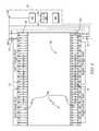
- FIG. 4is a diagrammatic plan view of the patient support system of FIGS. 1-3 ;
- FIG. 5is a perspective view of another embodiment of a mattress of the similar to that of the patient support system of FIGS. 1-3 configured such that the extension chambers are in an inflated mode;
- FIG. 6is a perspective view of the mattress of the patient support system of FIGS. 1-3 according to the present disclosure and configured such that the extension chambers are in a deflated mode;
- FIG. 7is a top perspective view of the deck of the patient support system of FIGS. 1-3 having a first embodiment for attachment of the extension chambers according to the present disclosure
- FIG. 8is a top perspective view of the deck of the patient support system of FIGS. 1-3 having a second embodiment for attachment of the extension chambers according to the present disclosure
- FIG. 9Ais a side view of the bed of the patient support system of FIGS. 1-3 according to the present disclosure with the extension chambers deflated;
- FIG. 9Bis a side view of the bed of the patient support system of FIGS. 1-3 according to the present disclosure with the extension chambers inflated;
- FIG. 10is a diagrammatic flow chart of a sequence of the patient support system of FIGS. 1-3 according to the present disclosure.
- Patient support systems for use in care facilitiesmay include patient support devices.
- Patient support devicessuch as beds
- Patient support devices that can accommodate bariatric patientscan be enabled for easy maneuvering through facilities by being operable for width adjustment.
- Configured in a wide-width modea patient support system can comfortably accommodate a bariatric patient.
- Configured in a narrow-width modea patient support system can easily pass through conventionally sized areas, such as standard hospital doorways and hallways.
- a usersuch as a caretaker, can operate the bed to achieve configuration between the narrow-width mode to the wide-width mode.
- a patient support system 10includes a patient support device, embodied as a hospital bed 12 , as shown in FIGS. 1A and 1B .
- the bed 12illustratively includes a mattress 16 having a plurality of extension chambers 20 disposed therein on each side.
- the patient support system 10can be selectively operated between a narrow-width and a wide-width by directing pressurized fluid to and/or from chambers 20 .
- Adjustable width of the bed 12enables accommodation of bariatric patients while permitting easy passage of the bed 12 through conventionally sized areas, such as standard hospital doorways and hallways.
- the bed 12illustratively includes a frame 13 , a deck 14 , and a mattress 16 as shown in FIGS. 1A and 1B .
- the frame 13supports the deck 14 which, in turn, supports the mattress 16 as shown in FIGS. 1A-2B .
- the deck 14 of bed 12includes a center deck portion 22 and side deck portions 24 as illustratively suggested in FIGS. 2A and 2B .
- the mattress 16includes a center mattress portion 18 and side mattress portions 19 that illustratively include extension chambers 20 as shown in FIGS. 1A-2B .
- the deck 14 and the mattress 16can be operated between a retracted-width and an extended-width by directing pressurized fluid to and/or from the chambers 20 of the mattress 16 by a bed extension control system 65 as shown in FIGS. 1, 2, and 4 .
- the mattress 16is illustratively positioned on top of the deck 14 and defines a patient support surface 30 .
- the extension chambers 20can be inflated by a bed extension control system 65 to create an additional patient support surface 32 .
- the patient support surface 30 and the additional patient support surface 32together define an extended patient support surface 34 .
- the extension chambers 20can be deflated to collapse the additional patient support surface 32 .
- the center mattress portion 18is supported by the center deck portion 22 of the deck 14 .
- the side mattress portions 19are supported by side deck portions 24 .
- Deflation and inflation of the extension chambers 20drives the side deck portions 24 respectively between a retracted position (suggested in FIGS. 1A and 2A ) and an extended position (suggested in FIGS. 2A and 2B ) without separate powered extension drive for the side deck portions 24 .
- the side deck portions 24are driven outwardly to support the additional patient support surface 32 .
- a caregivercan thus configure the bed 12 between a narrow mode having the patient support surface 30 and a wide mode having the extended patient support surface 34 .
- the mattress 16includes the extension chambers 20 as shown in FIGS. 1-4 .
- the extension chambers 20are illustratively attached to the center mattress portion 18 at each lateral side 26 of the center mattress portion 18 as shown in FIG. 3 .
- the length and width of the center mattress portion 18illustratively correspond to the length and width of the center deck portion 22 , respectively.
- the width of the extension chambers 20 in the extension directioncorrespond to the width of the side deck portions 24 in the extension direction.
- the extension chambers 20are width extension bladders as shown in FIG. 3 .
- the extension chambers 20are illustratively arranged within an outer mattress cover 21 that includes upper ticking 27 and lower ticking 29 as shown in FIG. 4 .
- the extension chambers 20illustratively define individual fluid bladders arranged to extend in the extension direction (lateral direction) and align with respective support bladders 23 within the center mattress portion 18 as shown in FIGS. 1-3 .
- the extension chambers 20are illustratively equal to each other in size and shape and are positioned successively from the head end to foot end of the mattress 16 along the longitudinal sides 26 of the center mattress portion 18 with contact between adjacent extension chambers 20 .
- the extension chambers 20may comprise one or more bladders extending lengthwise from head to foot of the bed 12 .
- the side deck portions 24are connected to the center deck portion 22 at opposing lateral sides 28 of the center deck portion 22 as illustratively shown in FIGS. 2A and 2B .
- the side deck portions 24are illustratively slidingly connected to the center deck portion 22 and configured to be movable between a retracted position (shown in FIGS. 2A and 9A ) and an extended position (shown in FIGS. 2B and 9B ) according to the configuration of the extension chambers.
- a retracted positionshown in FIGS. 2A and 9A
- an extended positionshown in FIGS. 2B and 9B
- the side deck portions 24are mounted to the center deck portion 22 by a roller track connection in which the side deck portions 24 include tracks 36 having a lower side 38 supported by contact with a top side of track wheels 40 that are rotatably mounted to the center deck portion 22 .
- the extension chambers 20are illustratively shown in the deflated state with the side deck portions 24 illustratively in the retracted position.
- the side deck portions 24Upon inflation of the extension chambers 20 , the side deck portions 24 are driven outwardly from the center deck portion 22 and slide outwardly toward an extended position illustrated in FIG. 2B .
- the side deck portions 24Upon deflation of the extension chambers 20 , the side deck portions 24 are driven inwardly towards the center deck portion 22 and slide inwardly toward a retracted position illustrated in FIG. 2A .
- the tracks 36 of the side deck portions 24ride along the track wheels 40 for smooth and sliding translation of the side deck portions 24 between the retracted and the extended positions indicated by arrows 39 as illustratively suggested in FIGS.
- the side deck portions 24may be connected to the center deck portion 22 by any suitable manner to provide smooth movement between the retracted and extended positions, such as rolling, sliding, telescoping, articulating, rotating, translating, etc.
- the center deck portion 22comprises a head deck section 42 , an upper deck section 44 , a lower deck section 46 , and a foot deck section 48 .
- the side deck portions 24comprise head side deck portions 50 of the head deck section 42 , and side portions 52 from each of the upper, lower, and foot deck sections 44 , 46 , 48 as shown in FIG. 2B .
- the head deck section 42illustratively includes a number of head side deck portions 50 attached at each longitudinal side 28 of the center deck portion 22 on the head end of the bed 12 .
- One of the number of head side deck portions 50 on each lateral side 28 of the deck 14illustratively includes a rail 54 attached at an outward end 55 of the head side deck portion 50 and extending vertically from the head side deck portion 50 .
- Each of the upper deck section 44 , lower deck section 46 and foot deck section 48illustratively include corresponding side deck portions 52 .
- the foot side deck portions 52each have a rail 54 attached at an outward end 55 of the foot side deck portions 52 and extending vertically from the foot side deck portion 52 .
- each extension chamber 20is illustratively attached to one of the side deck portions 24 by a mechanical fastener 56 .
- a portion of the mechanical fastener 56is mounted on a top side 58 of the one of the side deck portions 24 and arranged for connection to another portion of the mechanical fastener 56 that is fixed to a bottom side 60 of one of the extension chambers 20 (suggested in FIG. 3 ).
- the lower ticking 29may include holes 57 (phantom) on a bottom side thereof through which the portions of each mechanical fastener 56 can penetrate to connect with each other.
- the mechanical fasteners 56are illustratively embodied as snap fasteners configured to transfer the lateral forces of inflation and deflation of the extension chambers 20 to the respective side deck portions 24 to achieve sliding extension and retraction of the side deck portions 24 .
- the fasteners 56may be any fastener suitable to transfer the lateral forces of inflation and deflation of the extension chambers 20 to the respective side deck portions 24 to achieve sliding extension and retraction of the side deck portions 24 .
- the side deck portions 24support the extension chamber 20 to provide the additional patient support surface 32 .
- a portion of the mechanical fastener 56may be mounted to an inner side of a flange 62 extending perpendicularly from a top side 58 of each side deck portion 24 , as shown in FIG. 8 , and another portion of the mechanical fastener 56 may be mounted on an outer side of each extension chamber 20 for connection with the portion of the mechanical fastener 56 mounted on the flange 62 as shown in FIGS. 9A-B .
- the portion of the fastener 56 on the extension chamber 20illustratively penetrates holes 57 in the mattress cover 31 ( FIG. 3 ) for connection with the portion of the fastener 56 on the flange 62 .
- the mechanical fastener 56is a single mechanical snap. In some embodiments, the mechanical fastener 56 may be any number of mechanical fasteners for providing attachment of the extension chambers 20 and the side deck portions 24 to allow the extension chambers 20 to drive the side deck portions 24 between a retracted position and an extended position.
- the mattress 16includes foam bolsters 92 positioned on lateral sides of the extension chambers 20 and cooperating with the cover 31 to define a portion of the patient support surface 30 .
- One of the foam bolsters 92is illustratively positioned between the center mattress portion 18 and the extension chambers 20 .
- Another of the foam bolsters 92is illustratively positioned at the outward end in the extension direction of the extension chambers 20 of each side of the mattress 16 as shown in FIG. 5 .
- the foam bolsters 92 on opposite sides of the extension chamber 20are in a widely spaced-apart relation as shown in FIG. 5 .
- the foam bolsters 92 on opposite sides of the extension chamber 20are in a narrowly spaced-apart relation, which can include a contacting relation, as shown in FIG. 6 .
- the foam bolsters 92are configured provide support at the functional edges of the patient support surfaces 30 , 34 .
- bed extension control system 65includes the fluid supply system 64 , the bed extension controller 80 , and a user interface 86 .
- the fluid supply system 64supplies pressurized fluid to and from the extension chambers 20 for inflation and deflation thereof according to the bed extension controller 80 .
- a fluid supply device 66provides pressurized fluid to and from the extension chambers 20 . Ingress of pressurized fluid to the extension chambers 20 increases the pressure within the extension chambers 20 to inflate the extension chambers 20 to an inflated state suggested in FIGS. 1B and 2B . Egress of pressurized fluid from the extension chambers 20 decreases the pressure within the extension chambers 20 to deflate the extension chambers 20 to a deflated state suggested in FIGS. 1A and 2A .
- the fluid supply system 64includes the fluid supply device 66 , fluid communication lines 68 , and fluid control valves 70 as illustratively suggested in FIG. 4 .
- the fluid supply device 66provides pressurized fluid, typically air, to and from the extension chambers 20 to inflate and deflate the extension chambers 20 for extension and retraction of the side deck portions 24 and selective creation of the additional patient support surface 32 as mentioned above.
- the fluid supply device 66is a reversible pump configured to provide pressurized air to the extension chambers 20 in a pressurize mode and to suction air from the extension chambers 20 in a suction mode.
- the fluid communication lines 68communicate fluid, through the fluid control valves 70 , between the fluid supply device 66 and the extension chambers 20 .
- fluidis communicated to each extension chamber 20 through a dedicated fluid communication line 68 and dedicated fluid control valve 70 .
- the fluid supply system 64 and the extension chambers 20are configured for individualized control of fluid ingress and egress, including with commensurate individualized commands signals mentioned below.
- fluid supply system 64 and the extension chambers 20may be configured for control as part of a group of extension chambers 20 , for example, a group of extension chambers 20 which are attached to a common side deck portion 24 , a common one of the head side deck portions 50 , a common one of the upper, lower, and/or foot side deck portions 52 , and/or any combination thereof.
- group controlmay include any combination of shared and/or dedicated fluid supply system components with common command signals.
- the fluid supply device 66 and fluid control valves 70are configured to receive command signals from a bed extension controller 80 that configures the fluid supply device 66 and fluid control valves 70 accordingly to permit fluid communication to inflate and/or deflate the extension chambers 20 to achieve extension and retraction of the side deck portions 24 according to user inputs.
- a bed extension controller 80receives the user input, determines the requirements to achieve the new configuration, and performs the desired adjustment.
- the bed extension controller 80illustratively includes a processor 82 and a memory device 84 as shown in FIG. 2 .
- the processor 82is configured to receive one or more signals indicative of a user input indicating the desired position of the side deck portions 24 between a retracted and an extended position, and one or more signals indicative of a current position of the side deck portions 24 .
- the bed extension controller 80receives a signal indicating a desired bed width as user input, and receives signals indicating the current position of the side deck portions 24 .
- the processor 82determines the requirements of the extension chambers 20 and the fluid supply system 64 required to achieve the desired bed width, and sends a number of command signals to the fluid supply system 64 to achieve the position of the side deck portions 24 according to desired bed width indicated by the user input.
- the bed extension controller 80receives signals indicating the user input and the current position of the side deck portions 24 .
- the bed extension controller 80determines the required state of the extension chambers 20 to achieve the desired bed width according to the user input and the current position of the side deck portions 24 .
- the controller 80determines the operable positions of the components of the fluid supply system 64 required to achieve the required state of the extension chambers 20 determined in step 104 .
- the bed extension controller 80sends command signals indicative of the operable positions of the components of the fluid supply system 64 , as determined in step 106 , to the fluid supply system components.
- step 110the bed extension controller 80 determines whether the actual position matches the desired bed width.
- Step 110is illustratively embodied as sensing the pressure within the chambers 20 via sensors 90 to determine if the actual position of the side deck portions 24 corresponds to the desired bed width indicated by the user input. In some embodiments, determining whether the desired bed width has been achieved can be carried out by direct and/or indirect measurement, inference, estimate, and/or any combination thereof.
- the bed extension controller 80determines the requirements of the extension chambers 20 , the current position of the side deck portions 24 , and the operable positions of the fluid supply system components by execution of instructions.
- the memory device 84store the instructions that, when executed by the processor 82 , determine the requirements of the extension chambers 20 , the current position of the side deck portions 24 , and the operable conditions of the fluid supply device 66 and fluid control valves 70 required to achieve communication of fluid between the fluid supply device 66 and the extension chambers 20 to achieve extension and retraction of the side deck portions 24 , while providing adequate pressure to create additional patient support surface 32 , based on the current position of the side deck portions 24 and the user input.
- the instructionsinclude at least one algorithm configured to perform controller functions. In some embodiments, the instructions may include an automated sub-routine to maintain and/or adjust the pressure within the extension chambers 20 .
- the bed extension controller 80may send commands signals to the fluid supply device 66 to operate in the pressurize mode and to the fluid control valves 70 to permit communication of fluid to provide pressurized fluid to the extension chambers 20 . If the bed extension controller 80 determines based on the user input and the current position that the side deck portions 24 require retraction, the bed extension controller 80 may send commands signals to the fluid supply device 66 to operate in the suction mode and to the fluid control valves 70 to permit communication of fluid to remove fluid to the extension chambers 20 . Operating of the fluid supply device 66 in one of the pressurize or suction mode while in communication with the chambers 20 drives the side deck portions 24 in one of the retraction or extension directions respectively.
- signals indicative of a current position of the side deck portions 24include signals indicative of pressure levels of the extension chambers 20 as determined by pressure sensors 90 of the bed extension control system 65 as illustratively suggested in FIG. 4 .
- Signals indicative of a user inputillustratively include inputs from the user interface 86 .
- signals indicative of a current position of the side deck portions 24may include signals from any type of mechanical and/or electrical sensor suitable to indicate the position of the side deck portions 24 relative to the center deck portion 22 .
- signals from either or both of the user interface 86 and pressure sensors 90may be received by intermediary circuitry, which may include processors and/or other circuitry components, for determining signals for communication to the bed extension controller 80 .
- the bed 12includes a bias member 25 , embodied as elastic bands, configured to provide compressive force to the extension chambers 20 to assist the fluid supply device 66 in suction mode to perform deflation of the extension chambers 20 as shown in FIGS. 5-6 and retraction of the side deck portions 24 .
- the bias member 25may comprise any device configured to provide compressive force to evacuate and deflate the extension chambers 20 .
- the bias member 25may be configured to provide required force to compress extension chambers 20 into the deflated state and to retract the side deck portions 24 , and the bed extension controller 80 may be configured to send command signals to a deflation valve 94 of the fluid supply system 64 to evacuate fluid within the extension chambers 20 to atmosphere based on a user input and the current position.
- bias member 25may be excluded and the fluid supply device 66 may provide fluid evacuation to deflate the extension chambers 20 .
- the bed 12includes locks 88 configured to maintain a position of the side deck portions 24 relative to the center deck portion 22 as shown in FIGS. 9A and 9B .
- the locks 88comprise an electro-mechanical latch, for example a solenoid cylinder mounted to the bed and selectively engaging the side deck portion 24 .
- the solenoidmay be biased to extend through a portion of the side deck portion 24 to maintain the side deck portions 24 in a fixed position and configured to receive a control signal from the bed extension controller 80 to retract the cylinder from the side deck portion 24 to permit sliding movement of the side deck portions 24 .
- locks 88may comprise any type and/or arrangement of locking devices including but not limited to mechanical locks and/or controller based and/or software based locks, including combinations thereof, suitably arranged to fix the position of the side deck portions 24 when translation is not being undertaken by the side deck portions 24 as determined by the bed extension controller 80 .
- the extension chambers 20provide the drive force to extend and retract the side deck portions 24 while providing the additional patient support surface 32 .
- the extension chambers 20provide the only powered extension drive force such that no other powered extension drive mechanism is used to extend the side deck portions 24 .
- the extension chambers 20are inflated sufficiently to overcome the force of bias members, such as bias members 25 , with the side deck portions 24 being locked in place with the locks 88 , such that the pressure in the extension chambers 20 can be reduced to a pressure suitable for supporting a patient, the support pressure being lower than the pressure necessary to extend the side deck portions 24 .
- the locks 88are released and the bias members 25 assist with the retraction.
- the bias members 25may be employed in any of the embodiments disclosed herein.
- the bed 12may include various bed controllers for controller of various other bed operations being in addition to and in communication with bed extension controller 80 .
- bed extension controller 80may include one or more of shared hardware and/or of shared software components with those of other bed controllers.
- bed extension controller 80may include one or more interface connections configured for communication with other devices and may be configured to receive updates, debugging, and/or other modifications and/or additions to its memory.
- Sensors, controllers, and other devices that explicitly and/or implicitly communicate, indicate, receive, and/or transmit any information, communications, indications, transmissions, and/or signalsmay include one or more receivers, transmitters, and/or combined receiver/transmitters as required to perform their functions.
- Communications, signals, transmissions, and indicationsmay be carried out, partly or wholly, through one or more of wireless and wired connections and may include one or more intermediary devices between the source and the destination.
Landscapes
- Health & Medical Sciences (AREA)
- Nursing (AREA)
- Life Sciences & Earth Sciences (AREA)
- Animal Behavior & Ethology (AREA)
- General Health & Medical Sciences (AREA)
- Public Health (AREA)
- Veterinary Medicine (AREA)
- Invalid Beds And Related Equipment (AREA)
Abstract
Description
Claims (20)
Priority Applications (1)
| Application Number | Priority Date | Filing Date | Title |
|---|---|---|---|
| US15/214,530US10426680B2 (en) | 2015-07-31 | 2016-07-20 | Air bladder control of mattress/frame width expansion |
Applications Claiming Priority (2)
| Application Number | Priority Date | Filing Date | Title |
|---|---|---|---|
| US201562199610P | 2015-07-31 | 2015-07-31 | |
| US15/214,530US10426680B2 (en) | 2015-07-31 | 2016-07-20 | Air bladder control of mattress/frame width expansion |
Publications (2)
| Publication Number | Publication Date |
|---|---|
| US20170027786A1 US20170027786A1 (en) | 2017-02-02 |
| US10426680B2true US10426680B2 (en) | 2019-10-01 |
Family
ID=56551315
Family Applications (1)
| Application Number | Title | Priority Date | Filing Date |
|---|---|---|---|
| US15/214,530Active2037-12-02US10426680B2 (en) | 2015-07-31 | 2016-07-20 | Air bladder control of mattress/frame width expansion |
Country Status (2)
| Country | Link |
|---|---|
| US (1) | US10426680B2 (en) |
| EP (1) | EP3123997B1 (en) |
Cited By (3)
| Publication number | Priority date | Publication date | Assignee | Title |
|---|---|---|---|---|
| US10821042B1 (en)* | 2018-03-27 | 2020-11-03 | Beatrice Williams | Patient bed with mattress and integrated bed pan |
| US11259975B2 (en)* | 2018-10-13 | 2022-03-01 | Breanne O'Leary | Apparatus providing extension of a surgical table width allowing adaptation to the parameters of the specific patient |
| US11484449B2 (en) | 2019-08-13 | 2022-11-01 | Stryker Corporation | Support apparatus for bariatric person |
Families Citing this family (5)
| Publication number | Priority date | Publication date | Assignee | Title |
|---|---|---|---|---|
| US10463554B2 (en)* | 2016-05-09 | 2019-11-05 | Span-America Medical Systems, Inc. | Adjustable width user support |
| USD909805S1 (en)* | 2018-02-15 | 2021-02-09 | Michael F. Kunde | Transfer bar |
| US10617583B1 (en)* | 2019-09-25 | 2020-04-14 | King Sand University | Bed with retractable side extension |
| CA3207468A1 (en)* | 2022-07-22 | 2024-01-22 | Stryker Corporation | Patient support |
| CN115363376B (en)* | 2022-09-13 | 2023-11-03 | 慕思健康睡眠股份有限公司 | Adjustable mattress |
Citations (90)
| Publication number | Priority date | Publication date | Assignee | Title |
|---|---|---|---|---|
| US3220021A (en) | 1964-04-09 | 1965-11-30 | Nelson Ted | Adjustable seat length hospital bed |
| US3220022A (en) | 1963-12-23 | 1965-11-30 | Nelson Ted | Hospital bed sliding foot section |
| US3413663A (en) | 1967-02-23 | 1968-12-03 | David T. Swann | Combination stretcher, table, chair combination |
| US3893197A (en) | 1974-02-11 | 1975-07-08 | Maurine E Ricke | Hospital bed footboard assembly |
| US4409695A (en) | 1981-02-03 | 1983-10-18 | Burke, Inc. | Adjustable bed for morbidly obese patients |
| US4486908A (en) | 1981-07-23 | 1984-12-11 | Schroeder Warren C | Support bed |
| US4669136A (en) | 1985-04-02 | 1987-06-02 | Med-Con Of Georgia, Inc. | Combination hospital bed and surgical table |
| US4700417A (en) | 1986-07-16 | 1987-10-20 | Mcgovern Lorayne | Gurney extension |
| US4805249A (en) | 1986-09-19 | 1989-02-21 | Pulukadang Freddy Usman | Rehabilitation bed |
| US4847929A (en) | 1986-12-02 | 1989-07-18 | Milenko Pupovic | Bed with adjustable positions |
| US4985946A (en) | 1989-07-28 | 1991-01-22 | Hill-Rom Company, Inc. | Hospital bed adapted for use with a C-arm |
| US4987623A (en) | 1990-01-26 | 1991-01-29 | Stryker Corporation | Hospital stretcher having patient transfer device and side rails with handle portions |
| US5023967A (en) | 1988-03-23 | 1991-06-18 | American Life Support Technology | Patient support system |
| US5077843A (en) | 1990-07-28 | 1992-01-07 | Hill-Rom Company, Inc. | Hospital bed and assemblies of hospital care apparatus |
| US5083332A (en) | 1989-07-28 | 1992-01-28 | Hill-Rom Company, Inc. | Hospital bed with collapsible side edges and laterally-movable side guards |
| US5179744A (en) | 1989-07-28 | 1993-01-19 | Hill-Rom Company, Inc. | Hospital bed with inflatable and collapsible side edges and laterally-movable side guards |
| US5377370A (en) | 1993-06-10 | 1995-01-03 | Hill-Rom Company, Inc. | Hospital bed with collapsing wing |
| US5398357A (en) | 1993-06-03 | 1995-03-21 | Hill-Rom Company, Inc. | Hospital bed convertible to chair configuration |
| US5479666A (en) | 1994-01-25 | 1996-01-02 | Hill-Rom Company, Inc. | Foot egress chair bed |
| US5628078A (en) | 1994-08-15 | 1997-05-13 | Midmark Corporation | Surgical table side extender assembly |
| US5724685A (en) | 1995-08-04 | 1998-03-10 | Hill-Rom, Inc. | Step deck for a bed |
| US5745936A (en) | 1995-01-19 | 1998-05-05 | Windryder Engineering, Inc. | Safety bed with dual purpose side panels |
| US5802646A (en) | 1995-11-30 | 1998-09-08 | Hill-Rom, Inc. | Mattress structure having a foam mattress core |
| US5815865A (en) | 1995-11-30 | 1998-10-06 | Sleep Options, Inc. | Mattress structure |
| WO1999015126A2 (en) | 1997-09-23 | 1999-04-01 | Hill-Rom, Inc. | Hospital bed having a retracting foot section |
| US6021533A (en) | 1997-08-25 | 2000-02-08 | Hill-Rom, Inc. | Mattress apparatus having a siderail down sensor |
| US20010044971A1 (en) | 2000-02-07 | 2001-11-29 | Borders Richard L. | Bariatric surface for an operating room table |
| US6324709B1 (en) | 1998-07-31 | 2001-12-04 | France Bed Co., Ltd. | Mattress apparatus and bed apparatus |
| US6357065B1 (en) | 1999-11-15 | 2002-03-19 | Mellen Air Manufacturing, Inc. | Variable width bariatric modularbed |
| US6374438B1 (en) | 2000-04-11 | 2002-04-23 | Steris Inc | Treatment stretcher adapted for C-arm access |
| US6427264B1 (en) | 1999-03-19 | 2002-08-06 | Hill-Rom Services, Inc. | Gap filler for bed |
| US20020133883A1 (en) | 1999-01-08 | 2002-09-26 | Hill-Rom Services, Inc. | Mattress assembly |
| US6460209B1 (en) | 1995-11-30 | 2002-10-08 | Hill-Rom Services, Inc. | Mattress structure |
| US6499167B1 (en) | 1995-08-04 | 2002-12-31 | Hill-Rom Services, Inc. | Mattress section support |
| US20030159219A1 (en) | 2002-02-22 | 2003-08-28 | Harrison Samuel W. | Overlay mattress |
| US6615426B1 (en) | 1999-10-15 | 2003-09-09 | Hill-Rom Services, Inc. | Siderail pad for hospital bed |
| US20030167568A1 (en) | 2001-12-20 | 2003-09-11 | Brooke Jason C. | Bed siderails |
| US6694549B2 (en) | 2001-04-20 | 2004-02-24 | Hill-Rom Services, Inc. | Bed frame with reduced-shear pivot |
| US20040034931A1 (en) | 1995-08-04 | 2004-02-26 | Kummer Joseph A. | Hospital bed having a siderail position detector |
| US6820293B2 (en) | 2002-09-26 | 2004-11-23 | Hill-Rom Services, Inc. | Bed siderail pad apparatus |
| US20040255386A1 (en) | 2003-06-18 | 2004-12-23 | Liu Tsung Hsi | Width-adjustable alternating air inflation mattress |
| US20050028289A1 (en) | 2002-08-08 | 2005-02-10 | Reza Hakamiun | Mattress |
| US6880189B2 (en) | 1999-12-29 | 2005-04-19 | Hill-Rom Services, Inc. | Patient support |
| US20050081295A1 (en) | 2003-10-20 | 2005-04-21 | Malcolm Roger J. | Surgical table width extension and angularly orientable attachment |
| US20050172405A1 (en) | 2002-09-06 | 2005-08-11 | Menkedick Douglas J. | Hospital bed |
| US6971132B2 (en) | 2003-09-16 | 2005-12-06 | Feinsod Fred M | Mattress with hand supports |
| US20060021142A1 (en) | 2004-07-30 | 2006-02-02 | Hornbach David W | Patient support having powered adjustable width |
| US20060026767A1 (en)* | 2004-08-04 | 2006-02-09 | Chambers Kenith W | Mattress system for a hospital bed |
| US20060026762A1 (en) | 2004-07-28 | 2006-02-09 | Hornbach David M | Hospital bed |
| US20060026768A1 (en) | 2004-08-04 | 2006-02-09 | Chambers Kenith W | Hospital bed |
| US20060053562A1 (en) | 2004-09-13 | 2006-03-16 | Craig Poulos | Mattress for a hospital bed |
| US20060053555A1 (en) | 2004-09-13 | 2006-03-16 | Craig Poulos | Bed having fixed length foot deck |
| US20060059621A1 (en) | 2004-09-13 | 2006-03-23 | Craig Poulos | Siderail for hospital bed |
| US20060059624A1 (en) | 2004-09-13 | 2006-03-23 | Craig Poulos | Expandable width bed |
| US20060090261A1 (en) | 1995-01-31 | 2006-05-04 | Kci Licensing, Inc. | Bariatric bed apparatus and methods |
| US20060101580A1 (en) | 2004-11-18 | 2006-05-18 | Sentech Medical Systems, Inc. | Adjustable Width Bariatric Transport Support Surface |
| US20060162075A1 (en) | 2003-01-14 | 2006-07-27 | Simplicity, Inc. | Adjustable bed rail |
| US20060168728A1 (en)* | 2002-12-26 | 2006-08-03 | Strobel Frederic W | Bariatric patient management system |
| US20060195984A1 (en) | 2005-03-07 | 2006-09-07 | Reza Hakamiun | Siderail for a hospital bed |
| US20070000056A1 (en) | 2005-06-29 | 2007-01-04 | Philip Ward | Stretcher |
| US7200882B2 (en) | 2004-01-22 | 2007-04-10 | Hill-Rom Services, Inc. | Movable control panel for a patient support |
| US7225489B1 (en)* | 2006-04-19 | 2007-06-05 | Sunflower Medical, L.L.C. | Expandable seamless mattress assembly |
| US20070136949A1 (en) | 2005-12-19 | 2007-06-21 | Sandy Richards | Patient support having an extendable foot section |
| US20070180617A1 (en) | 2001-08-22 | 2007-08-09 | Kramer Kenneth L | Apparatus and method for closing hospital bed gaps |
| US20070234482A1 (en) | 2006-04-05 | 2007-10-11 | Scot Wright | Mattress extension system |
| US20080000028A1 (en) | 2006-06-28 | 2008-01-03 | Stryker Corporation | Patient support |
| US20080040857A1 (en) | 2004-07-02 | 2008-02-21 | Karmer Duwayne E Jr | Bariatric transport with improved maneuverability |
| US20080201844A1 (en) | 2000-10-19 | 2008-08-28 | Sebastien Gemeline | Bed With Simultaneously Movable Barrier and Bed Plane Elements |
| US20080282469A1 (en) | 2005-07-20 | 2008-11-20 | Stephen Hayes | Hinge For Bed Frame Assembly |
| US20090229050A1 (en) | 2008-03-13 | 2009-09-17 | Hill-Rom Services, Inc. | Siderail gap filler |
| US20090293197A1 (en) | 2008-05-30 | 2009-12-03 | Joerns Healthcare Inc. | Width adjustment accessory for use with beds |
| US20100005592A1 (en) | 2008-06-27 | 2010-01-14 | Craig Poulos | Bed with modified foot deck |
| US7917978B2 (en) | 2004-03-12 | 2011-04-05 | Hill-Rom Services, Inc. | Variable height siderail for a bed |
| US7930778B2 (en) | 2007-12-07 | 2011-04-26 | Hill-Rom Services, Inc. | Pinch-preventing unit for bed guardrail |
| US20110113561A1 (en) | 2009-11-18 | 2011-05-19 | Douglas Stephen L | Method and apparatus for sensing foot retraction in a mattress replacement system |
| US20110232001A1 (en) | 2008-06-27 | 2011-09-29 | Craig Poulos | Bed gap filler |
| US20120198629A1 (en) | 2011-02-04 | 2012-08-09 | Hornbach David W | Adjustable foot section for a patient support apparatus |
| US8239986B2 (en) | 2008-03-13 | 2012-08-14 | Hill-Rom Services, Inc. | Siderail assembly for a patient-support apparatus |
| US20120271350A1 (en) | 2011-04-22 | 2012-10-25 | ROM-T Enterprises LLC | Range of motion table |
| US8341778B2 (en) | 2011-02-07 | 2013-01-01 | Hill-Rom Services, Inc. | Bed gap filler and footboard pad |
| WO2013058753A1 (en) | 2011-10-20 | 2013-04-25 | Ferno-Washington, Inc. | Work surface extensions for embalming tables and embalming tables including the same |
| US8453283B2 (en) | 2010-11-03 | 2013-06-04 | Hill-Rom Services, Inc. | Patient support apparatus with movable siderail assembly |
| US20130227787A1 (en) | 2012-03-02 | 2013-09-05 | Stryker Corporation | Patient support |
| US8539625B2 (en) | 2009-09-23 | 2013-09-24 | Kreg Medical Inc. | Bed gap shield |
| US20130298331A1 (en) | 2012-05-10 | 2013-11-14 | Robert Bossingham | Bed with a Powered Width Expansion Wing |
| US20140026325A1 (en)* | 2012-07-25 | 2014-01-30 | Joerns Healthcare, Llc | Adjustable Width Mattress |
| US8789224B2 (en) | 2000-11-07 | 2014-07-29 | Tempur-Pedic Managemant, LLC | Therapeutic mattress assembly |
| US8898838B1 (en) | 2014-01-25 | 2014-12-02 | Ton Duc Thang University | Method and apparatus for a convertible patient bed |
| US9089459B2 (en) | 2013-11-18 | 2015-07-28 | Völker GmbH | Person support apparatus |
| US9173797B2 (en) | 2010-12-13 | 2015-11-03 | Hill-Rom Services, Inc. | Siderail assembly for patient support apparatus |
Family Cites Families (1)
| Publication number | Priority date | Publication date | Assignee | Title |
|---|---|---|---|---|
| US11642260B2 (en)* | 2012-08-17 | 2023-05-09 | Hill-Rom Services, Inc. | Variable width hospital bed |
- 2016
- 2016-07-20USUS15/214,530patent/US10426680B2/enactiveActive
- 2016-07-28EPEP16181634.3Apatent/EP3123997B1/enactiveActive
Patent Citations (155)
| Publication number | Priority date | Publication date | Assignee | Title |
|---|---|---|---|---|
| US3220022A (en) | 1963-12-23 | 1965-11-30 | Nelson Ted | Hospital bed sliding foot section |
| US3220021A (en) | 1964-04-09 | 1965-11-30 | Nelson Ted | Adjustable seat length hospital bed |
| US3413663A (en) | 1967-02-23 | 1968-12-03 | David T. Swann | Combination stretcher, table, chair combination |
| US3893197A (en) | 1974-02-11 | 1975-07-08 | Maurine E Ricke | Hospital bed footboard assembly |
| US4409695A (en) | 1981-02-03 | 1983-10-18 | Burke, Inc. | Adjustable bed for morbidly obese patients |
| US4486908A (en) | 1981-07-23 | 1984-12-11 | Schroeder Warren C | Support bed |
| US4669136A (en) | 1985-04-02 | 1987-06-02 | Med-Con Of Georgia, Inc. | Combination hospital bed and surgical table |
| US4700417A (en) | 1986-07-16 | 1987-10-20 | Mcgovern Lorayne | Gurney extension |
| US4805249A (en) | 1986-09-19 | 1989-02-21 | Pulukadang Freddy Usman | Rehabilitation bed |
| US4847929A (en) | 1986-12-02 | 1989-07-18 | Milenko Pupovic | Bed with adjustable positions |
| US5023967A (en) | 1988-03-23 | 1991-06-18 | American Life Support Technology | Patient support system |
| US5345629A (en) | 1988-03-23 | 1994-09-13 | American Life Support Technology | Patient support system |
| US4985946A (en) | 1989-07-28 | 1991-01-22 | Hill-Rom Company, Inc. | Hospital bed adapted for use with a C-arm |
| US5083332A (en) | 1989-07-28 | 1992-01-28 | Hill-Rom Company, Inc. | Hospital bed with collapsible side edges and laterally-movable side guards |
| US5179744A (en) | 1989-07-28 | 1993-01-19 | Hill-Rom Company, Inc. | Hospital bed with inflatable and collapsible side edges and laterally-movable side guards |
| US4987623A (en) | 1990-01-26 | 1991-01-29 | Stryker Corporation | Hospital stretcher having patient transfer device and side rails with handle portions |
| US5077843A (en) | 1990-07-28 | 1992-01-07 | Hill-Rom Company, Inc. | Hospital bed and assemblies of hospital care apparatus |
| US5398357A (en) | 1993-06-03 | 1995-03-21 | Hill-Rom Company, Inc. | Hospital bed convertible to chair configuration |
| US5377370A (en) | 1993-06-10 | 1995-01-03 | Hill-Rom Company, Inc. | Hospital bed with collapsing wing |
| US5479666A (en) | 1994-01-25 | 1996-01-02 | Hill-Rom Company, Inc. | Foot egress chair bed |
| US5628078A (en) | 1994-08-15 | 1997-05-13 | Midmark Corporation | Surgical table side extender assembly |
| US20070169271A1 (en) | 1995-01-03 | 2007-07-26 | Allen E D | Hospital bed and mattress having a retractable foot section |
| US5745936A (en) | 1995-01-19 | 1998-05-05 | Windryder Engineering, Inc. | Safety bed with dual purpose side panels |
| US7827632B2 (en) | 1995-01-31 | 2010-11-09 | Vrzalik John H | Bariatric bed apparatus and methods |
| US7426760B2 (en) | 1995-01-31 | 2008-09-23 | Kci Licensing, Inc. | Bariatric bed apparatus and methods |
| US20080289107A1 (en) | 1995-01-31 | 2008-11-27 | Kci Licensing, Inc. | Bariatric Bed Apparatus and Methods |
| US20060090261A1 (en) | 1995-01-31 | 2006-05-04 | Kci Licensing, Inc. | Bariatric bed apparatus and methods |
| US7802332B2 (en) | 1995-08-04 | 2010-09-28 | Hill-Rom Services, Inc. | Inflatable mattress for a bed |
| US8056165B2 (en) | 1995-08-04 | 2011-11-15 | Hill-Rom Services, Inc. | Inflatable mattress for a bed |
| US20060253982A1 (en) | 1995-08-04 | 2006-11-16 | Kummer Joseph A | Bed having electrical communication network |
| US7086107B2 (en) | 1995-08-04 | 2006-08-08 | Hill-Rom Services, Inc. | Mattress section support |
| US7216389B2 (en) | 1995-08-04 | 2007-05-15 | Hill-Rom Services, Inc. | Mattress section support |
| US7076818B2 (en) | 1995-08-04 | 2006-07-18 | Hill-Rom Services, Inc. | Hospital bed having a siderail position detector |
| US5940910A (en) | 1995-08-04 | 1999-08-24 | Hill-Rom, Inc. | Step deck for a bed |
| US5724685A (en) | 1995-08-04 | 1998-03-10 | Hill-Rom, Inc. | Step deck for a bed |
| US8286282B2 (en) | 1995-08-04 | 2012-10-16 | Hill-Rom Services, Inc. | Bed frame and mattress synchronous control |
| US20070180626A1 (en) | 1995-08-04 | 2007-08-09 | Ellis Craig D | Mattress section support |
| US6499167B1 (en) | 1995-08-04 | 2002-12-31 | Hill-Rom Services, Inc. | Mattress section support |
| US7353557B2 (en) | 1995-08-04 | 2008-04-08 | Hill-Rom Services, Inc. | Mattress section support |
| US20040034931A1 (en) | 1995-08-04 | 2004-02-26 | Kummer Joseph A. | Hospital bed having a siderail position detector |
| US20040133987A1 (en) | 1995-11-30 | 2004-07-15 | Reeder Ryan A. | Mattress structure |
| US6460209B1 (en) | 1995-11-30 | 2002-10-08 | Hill-Rom Services, Inc. | Mattress structure |
| US6687935B2 (en) | 1995-11-30 | 2004-02-10 | Hill-Rom Services, Inc. | Mattress structure |
| US5802646A (en) | 1995-11-30 | 1998-09-08 | Hill-Rom, Inc. | Mattress structure having a foam mattress core |
| US5815865A (en) | 1995-11-30 | 1998-10-06 | Sleep Options, Inc. | Mattress structure |
| US6378152B1 (en) | 1995-11-30 | 2002-04-30 | Hill-Rom Services, Inc. | Mattress structure |
| US6760939B2 (en) | 1997-08-25 | 2004-07-13 | Hill-Rom Services, Inc. | Mattress assembly |
| US6295675B1 (en) | 1997-08-25 | 2001-10-02 | Hill-Rom Services, Inc. | Mattress assembly |
| US7353556B2 (en) | 1997-08-25 | 2008-04-08 | Hill-Rom Services, Inc. | Mattress assembly |
| US6021533A (en) | 1997-08-25 | 2000-02-08 | Hill-Rom, Inc. | Mattress apparatus having a siderail down sensor |
| WO1999015126A2 (en) | 1997-09-23 | 1999-04-01 | Hill-Rom, Inc. | Hospital bed having a retracting foot section |
| US6324709B1 (en) | 1998-07-31 | 2001-12-04 | France Bed Co., Ltd. | Mattress apparatus and bed apparatus |
| US20020133883A1 (en) | 1999-01-08 | 2002-09-26 | Hill-Rom Services, Inc. | Mattress assembly |
| US6427264B1 (en) | 1999-03-19 | 2002-08-06 | Hill-Rom Services, Inc. | Gap filler for bed |
| US6704954B2 (en) | 1999-03-19 | 2004-03-16 | Hill-Rom Services, Inc. | Gap filler for bed |
| US6615426B1 (en) | 1999-10-15 | 2003-09-09 | Hill-Rom Services, Inc. | Siderail pad for hospital bed |
| US6357065B1 (en) | 1999-11-15 | 2002-03-19 | Mellen Air Manufacturing, Inc. | Variable width bariatric modularbed |
| US6880189B2 (en) | 1999-12-29 | 2005-04-19 | Hill-Rom Services, Inc. | Patient support |
| US9009893B2 (en) | 1999-12-29 | 2015-04-21 | Hill-Rom Services, Inc. | Hospital bed |
| US6678908B2 (en) | 2000-02-07 | 2004-01-20 | Hill-Rom Services, Inc. | Bariatric surface for an operating room table |
| US20010044971A1 (en) | 2000-02-07 | 2001-11-29 | Borders Richard L. | Bariatric surface for an operating room table |
| US20040143904A1 (en) | 2000-02-07 | 2004-07-29 | Hill-Rom Services, Inc. | Bariatric surface for an operating room table |
| US6374438B1 (en) | 2000-04-11 | 2002-04-23 | Steris Inc | Treatment stretcher adapted for C-arm access |
| US8510879B2 (en) | 2000-10-19 | 2013-08-20 | Hill-Rom S.A.S. | Bed with overlapping barriers |
| US7975332B2 (en) | 2000-10-19 | 2011-07-12 | Hill-Rom Services, Inc. | Bed with articulated barrier elements |
| US8205280B2 (en) | 2000-10-19 | 2012-06-26 | Hill-Rom S.A.S. | Overlapping barriers for a bed |
| US20080201844A1 (en) | 2000-10-19 | 2008-08-28 | Sebastien Gemeline | Bed With Simultaneously Movable Barrier and Bed Plane Elements |
| US8789224B2 (en) | 2000-11-07 | 2014-07-29 | Tempur-Pedic Managemant, LLC | Therapeutic mattress assembly |
| US6694549B2 (en) | 2001-04-20 | 2004-02-24 | Hill-Rom Services, Inc. | Bed frame with reduced-shear pivot |
| US20040158923A1 (en) | 2001-04-20 | 2004-08-19 | Hill-Rom Services, Inc. | Patient support having a siderail |
| US20070180617A1 (en) | 2001-08-22 | 2007-08-09 | Kramer Kenneth L | Apparatus and method for closing hospital bed gaps |
| US7788747B2 (en) | 2001-08-22 | 2010-09-07 | Hill-Rom Services, Inc. | Apparatus and method for closing hospital bed gaps |
| US20030167568A1 (en) | 2001-12-20 | 2003-09-11 | Brooke Jason C. | Bed siderails |
| US20030159219A1 (en) | 2002-02-22 | 2003-08-28 | Harrison Samuel W. | Overlay mattress |
| US20050028289A1 (en) | 2002-08-08 | 2005-02-10 | Reza Hakamiun | Mattress |
| US20050172405A1 (en) | 2002-09-06 | 2005-08-11 | Menkedick Douglas J. | Hospital bed |
| US7669263B2 (en) | 2002-09-06 | 2010-03-02 | Hill-Rom Services, Inc. | Mattress assembly including adjustable length foot |
| US7703158B2 (en) | 2002-09-06 | 2010-04-27 | Hill-Rom Services, Inc. | Patient support apparatus having a diagnostic system |
| US20080010748A1 (en) | 2002-09-06 | 2008-01-17 | Menkedick Douglas J | Patient support apparatus having controller area network |
| US6820293B2 (en) | 2002-09-26 | 2004-11-23 | Hill-Rom Services, Inc. | Bed siderail pad apparatus |
| US20060168728A1 (en)* | 2002-12-26 | 2006-08-03 | Strobel Frederic W | Bariatric patient management system |
| US20060162075A1 (en) | 2003-01-14 | 2006-07-27 | Simplicity, Inc. | Adjustable bed rail |
| US20040255386A1 (en) | 2003-06-18 | 2004-12-23 | Liu Tsung Hsi | Width-adjustable alternating air inflation mattress |
| US6971132B2 (en) | 2003-09-16 | 2005-12-06 | Feinsod Fred M | Mattress with hand supports |
| US7210180B2 (en) | 2003-10-20 | 2007-05-01 | Malcolm Roger J | Surgical table width extension and angularly orientable attachment |
| US20050081295A1 (en) | 2003-10-20 | 2005-04-21 | Malcolm Roger J. | Surgical table width extension and angularly orientable attachment |
| US7200882B2 (en) | 2004-01-22 | 2007-04-10 | Hill-Rom Services, Inc. | Movable control panel for a patient support |
| US7430771B2 (en) | 2004-01-22 | 2008-10-07 | Hill-Rom Services, Inc. | Movable control panel for a patient support |
| US7917978B2 (en) | 2004-03-12 | 2011-04-05 | Hill-Rom Services, Inc. | Variable height siderail for a bed |
| US20080040857A1 (en) | 2004-07-02 | 2008-02-21 | Karmer Duwayne E Jr | Bariatric transport with improved maneuverability |
| US20060026762A1 (en) | 2004-07-28 | 2006-02-09 | Hornbach David M | Hospital bed |
| US7406729B2 (en) | 2004-07-30 | 2008-08-05 | Hill-Rom Services, Inc. | Patient support having powered adjustable width |
| US20080282472A1 (en) | 2004-07-30 | 2008-11-20 | Hornbach David W | Patient support having powered adjustable width |
| US7730562B2 (en) | 2004-07-30 | 2010-06-08 | Hill-Rom Services, Inc. | Patient support having powered adjustable width |
| US20060021142A1 (en) | 2004-07-30 | 2006-02-02 | Hornbach David W | Patient support having powered adjustable width |
| US20060026767A1 (en)* | 2004-08-04 | 2006-02-09 | Chambers Kenith W | Mattress system for a hospital bed |
| US20110099723A1 (en) | 2004-08-04 | 2011-05-05 | Chambers Kenith W | Adjustable Width Mattress with Relief Portions |
| US20060026768A1 (en) | 2004-08-04 | 2006-02-09 | Chambers Kenith W | Hospital bed |
| US8122546B2 (en) | 2004-08-04 | 2012-02-28 | Hill-Rom Services, Inc. | Adjustable width mattress with relief portions |
| US7565710B2 (en) | 2004-08-04 | 2009-07-28 | Hill-Rom Services, Inc. | Support surface with inflatable width adjustment portion |
| US20060053562A1 (en) | 2004-09-13 | 2006-03-16 | Craig Poulos | Mattress for a hospital bed |
| US8069514B2 (en) | 2004-09-13 | 2011-12-06 | Kreg Medical, Inc. | Expandable width bed |
| US20060059621A1 (en) | 2004-09-13 | 2006-03-23 | Craig Poulos | Siderail for hospital bed |
| US8056160B2 (en) | 2004-09-13 | 2011-11-15 | Kreg Medical, Inc. | Siderail for hospital bed |
| US7676862B2 (en) | 2004-09-13 | 2010-03-16 | Kreg Medical, Inc. | Siderail for hospital bed |
| US20060059624A1 (en) | 2004-09-13 | 2006-03-23 | Craig Poulos | Expandable width bed |
| US20100107335A1 (en) | 2004-09-13 | 2010-05-06 | Craig Poulos | Siderail for hospital bed |
| US20060053555A1 (en) | 2004-09-13 | 2006-03-16 | Craig Poulos | Bed having fixed length foot deck |
| US7743441B2 (en) | 2004-09-13 | 2010-06-29 | Kreg Therapeutics, Inc. | Expandable width bed |
| US7757318B2 (en) | 2004-09-13 | 2010-07-20 | Kreg Therapeutics, Inc. | Mattress for a hospital bed |
| US7779494B2 (en) | 2004-09-13 | 2010-08-24 | Kreg Therapeutics, Inc. | Bed having fixed length foot deck |
| WO2006036523A1 (en) | 2004-09-13 | 2006-04-06 | Kreg Medical, Inc. | Expandable width bed |
| US20060101580A1 (en) | 2004-11-18 | 2006-05-18 | Sentech Medical Systems, Inc. | Adjustable Width Bariatric Transport Support Surface |
| US7805782B2 (en) | 2005-03-07 | 2010-10-05 | Hill-Rom Services, Inc. | Siderail for a hospital bed |
| US20060195984A1 (en) | 2005-03-07 | 2006-09-07 | Reza Hakamiun | Siderail for a hospital bed |
| US7676861B2 (en) | 2005-06-29 | 2010-03-16 | Ferno (Uk) Limited | Stretcher |
| US20070000056A1 (en) | 2005-06-29 | 2007-01-04 | Philip Ward | Stretcher |
| US20090113633A1 (en) | 2005-07-20 | 2009-05-07 | Stephen Hayes | Bed assembly |
| US8397324B2 (en) | 2005-07-20 | 2013-03-19 | Huntleigh Technology Limited | Hinge for bed frame assembly |
| US20080282469A1 (en) | 2005-07-20 | 2008-11-20 | Stephen Hayes | Hinge For Bed Frame Assembly |
| US20080295248A1 (en) | 2005-07-20 | 2008-12-04 | Stephen Hayes | Bed Assembly |
| US7895689B2 (en) | 2005-07-20 | 2011-03-01 | Huntleigh Technology Limited | Bed assembly |
| US8104122B2 (en) | 2005-12-19 | 2012-01-31 | Hill-Rom Services, Inc. | Patient support having an extendable foot section |
| US20070136949A1 (en) | 2005-12-19 | 2007-06-21 | Sandy Richards | Patient support having an extendable foot section |
| US20070234482A1 (en) | 2006-04-05 | 2007-10-11 | Scot Wright | Mattress extension system |
| US7225489B1 (en)* | 2006-04-19 | 2007-06-05 | Sunflower Medical, L.L.C. | Expandable seamless mattress assembly |
| US20080000028A1 (en) | 2006-06-28 | 2008-01-03 | Stryker Corporation | Patient support |
| US7930778B2 (en) | 2007-12-07 | 2011-04-26 | Hill-Rom Services, Inc. | Pinch-preventing unit for bed guardrail |
| US8296884B2 (en) | 2008-03-13 | 2012-10-30 | Hill-Rom Services, Inc. | Siderail gap filler |
| US20090229050A1 (en) | 2008-03-13 | 2009-09-17 | Hill-Rom Services, Inc. | Siderail gap filler |
| US8239986B2 (en) | 2008-03-13 | 2012-08-14 | Hill-Rom Services, Inc. | Siderail assembly for a patient-support apparatus |
| US20090293197A1 (en) | 2008-05-30 | 2009-12-03 | Joerns Healthcare Inc. | Width adjustment accessory for use with beds |
| US9320663B2 (en) | 2008-06-27 | 2016-04-26 | Kreg Medical, Inc. | Bed gap filler |
| US20110232001A1 (en) | 2008-06-27 | 2011-09-29 | Craig Poulos | Bed gap filler |
| US9119753B2 (en) | 2008-06-27 | 2015-09-01 | Kreg Medical, Inc. | Bed with modified foot deck |
| US20100005592A1 (en) | 2008-06-27 | 2010-01-14 | Craig Poulos | Bed with modified foot deck |
| US8539625B2 (en) | 2009-09-23 | 2013-09-24 | Kreg Medical Inc. | Bed gap shield |
| US20110113561A1 (en) | 2009-11-18 | 2011-05-19 | Douglas Stephen L | Method and apparatus for sensing foot retraction in a mattress replacement system |
| US8677536B2 (en) | 2009-11-18 | 2014-03-25 | Hill-Rom Services, Inc. | Method and apparatus for sensing foot retraction in a mattress replacement system |
| US8453283B2 (en) | 2010-11-03 | 2013-06-04 | Hill-Rom Services, Inc. | Patient support apparatus with movable siderail assembly |
| US8732875B2 (en) | 2010-11-03 | 2014-05-27 | Hill-Rom Services, Inc. | Patient support apparatus with movable siderail assembly |
| US9173797B2 (en) | 2010-12-13 | 2015-11-03 | Hill-Rom Services, Inc. | Siderail assembly for patient support apparatus |
| US20120198629A1 (en) | 2011-02-04 | 2012-08-09 | Hornbach David W | Adjustable foot section for a patient support apparatus |
| US8474076B2 (en) | 2011-02-04 | 2013-07-02 | Hill-Rom Services, Inc. | Adjustable foot section for a patient support apparatus |
| US8341778B2 (en) | 2011-02-07 | 2013-01-01 | Hill-Rom Services, Inc. | Bed gap filler and footboard pad |
| US20120271350A1 (en) | 2011-04-22 | 2012-10-25 | ROM-T Enterprises LLC | Range of motion table |
| US8997283B2 (en) | 2011-10-20 | 2015-04-07 | Ferno-Washington, Inc. | Work surface extensions for embalming tables and embalming tables including the same |
| WO2013058753A1 (en) | 2011-10-20 | 2013-04-25 | Ferno-Washington, Inc. | Work surface extensions for embalming tables and embalming tables including the same |
| US20130227787A1 (en) | 2012-03-02 | 2013-09-05 | Stryker Corporation | Patient support |
| US9381125B2 (en) | 2012-03-02 | 2016-07-05 | Stryker Corporation | Patient support |
| US8997282B2 (en) | 2012-05-10 | 2015-04-07 | Hill-Rom Services, Inc. | Bed with a powered width expansion wing |
| US20130298331A1 (en) | 2012-05-10 | 2013-11-14 | Robert Bossingham | Bed with a Powered Width Expansion Wing |
| US20140026325A1 (en)* | 2012-07-25 | 2014-01-30 | Joerns Healthcare, Llc | Adjustable Width Mattress |
| US9089459B2 (en) | 2013-11-18 | 2015-07-28 | Völker GmbH | Person support apparatus |
| US8898838B1 (en) | 2014-01-25 | 2014-12-02 | Ton Duc Thang University | Method and apparatus for a convertible patient bed |
Non-Patent Citations (1)
| Title |
|---|
| European Search Report for EP 16 18 1634 dated Dec. 12, 2016, 7 pages. |
Cited By (3)
| Publication number | Priority date | Publication date | Assignee | Title |
|---|---|---|---|---|
| US10821042B1 (en)* | 2018-03-27 | 2020-11-03 | Beatrice Williams | Patient bed with mattress and integrated bed pan |
| US11259975B2 (en)* | 2018-10-13 | 2022-03-01 | Breanne O'Leary | Apparatus providing extension of a surgical table width allowing adaptation to the parameters of the specific patient |
| US11484449B2 (en) | 2019-08-13 | 2022-11-01 | Stryker Corporation | Support apparatus for bariatric person |
Also Published As
| Publication number | Publication date |
|---|---|
| EP3123997A1 (en) | 2017-02-01 |
| EP3123997B1 (en) | 2018-03-14 |
| US20170027786A1 (en) | 2017-02-02 |
Similar Documents
| Publication | Publication Date | Title |
|---|---|---|
| US10426680B2 (en) | Air bladder control of mattress/frame width expansion | |
| EP2444047B1 (en) | Footboard with partial mattress integration | |
| EP3384890B1 (en) | Variable width hospital bed | |
| US10555850B2 (en) | Patient support systems and methods of use | |
| US12310905B2 (en) | Bed apparatus and patient detection method | |
| US8037563B2 (en) | Multiple air source mattress control system | |
| US10413464B2 (en) | Multi-mode sacral unloading pressure relief in a patient support surface | |
| US7975335B2 (en) | Pulmonary mattress | |
| EP2575723B1 (en) | Therapeutic support device allowing capillary blood flow | |
| US11730649B2 (en) | Patient turning device for a patient support apparatus | |
| US20110113561A1 (en) | Method and apparatus for sensing foot retraction in a mattress replacement system | |
| EP2968047B1 (en) | Patient support apparatus and method | |
| US20080235875A1 (en) | Maternity bed and patient lying surface therefor | |
| AU2020244416B1 (en) | Air distribution device and method applicable to patient support system | |
| US20250177233A1 (en) | System and method for simultaneously providing alternating low pressure therapy and skin cooling | |
| US20240148152A1 (en) | Expandable bed | |
| CN107928925A (en) | The pneumatic pillow bridge of counteracting bedsores |
Legal Events
| Date | Code | Title | Description |
|---|---|---|---|
| AS | Assignment | Owner name:JPMORGAN CHASE BANK, N.A., AS COLLATERAL AGENT, ILLINOIS Free format text:SECURITY AGREEMENT;ASSIGNORS:HILL-ROM SERVICES, INC.;ASPEN SURGICAL PRODUCTS, INC.;ALLEN MEDICAL SYSTEMS, INC.;AND OTHERS;REEL/FRAME:040145/0445 Effective date:20160921 Owner name:JPMORGAN CHASE BANK, N.A., AS COLLATERAL AGENT, IL Free format text:SECURITY AGREEMENT;ASSIGNORS:HILL-ROM SERVICES, INC.;ASPEN SURGICAL PRODUCTS, INC.;ALLEN MEDICAL SYSTEMS, INC.;AND OTHERS;REEL/FRAME:040145/0445 Effective date:20160921 | |
| STPP | Information on status: patent application and granting procedure in general | Free format text:RESPONSE TO NON-FINAL OFFICE ACTION ENTERED AND FORWARDED TO EXAMINER | |
| STPP | Information on status: patent application and granting procedure in general | Free format text:NOTICE OF ALLOWANCE MAILED -- APPLICATION RECEIVED IN OFFICE OF PUBLICATIONS | |
| STPP | Information on status: patent application and granting procedure in general | Free format text:PUBLICATIONS -- ISSUE FEE PAYMENT VERIFIED | |
| AS | Assignment | Owner name:HILL-ROM COMPANY, INC., ILLINOIS Free format text:RELEASE BY SECURED PARTY;ASSIGNOR:JPMORGAN CHASE BANK, N.A.;REEL/FRAME:050254/0513 Effective date:20190830 Owner name:ANODYNE MEDICAL DEVICE, INC., FLORIDA Free format text:RELEASE BY SECURED PARTY;ASSIGNOR:JPMORGAN CHASE BANK, N.A.;REEL/FRAME:050254/0513 Effective date:20190830 Owner name:MORTARA INSTRUMENT SERVICES, INC., WISCONSIN Free format text:RELEASE BY SECURED PARTY;ASSIGNOR:JPMORGAN CHASE BANK, N.A.;REEL/FRAME:050254/0513 Effective date:20190830 Owner name:HILL-ROM SERVICES, INC., ILLINOIS Free format text:RELEASE BY SECURED PARTY;ASSIGNOR:JPMORGAN CHASE BANK, N.A.;REEL/FRAME:050254/0513 Effective date:20190830 Owner name:VOALTE, INC., FLORIDA Free format text:RELEASE BY SECURED PARTY;ASSIGNOR:JPMORGAN CHASE BANK, N.A.;REEL/FRAME:050254/0513 Effective date:20190830 Owner name:HILL-ROM, INC., ILLINOIS Free format text:RELEASE BY SECURED PARTY;ASSIGNOR:JPMORGAN CHASE BANK, N.A.;REEL/FRAME:050254/0513 Effective date:20190830 Owner name:ALLEN MEDICAL SYSTEMS, INC., ILLINOIS Free format text:RELEASE BY SECURED PARTY;ASSIGNOR:JPMORGAN CHASE BANK, N.A.;REEL/FRAME:050254/0513 Effective date:20190830 Owner name:MORTARA INSTRUMENT, INC., WISCONSIN Free format text:RELEASE BY SECURED PARTY;ASSIGNOR:JPMORGAN CHASE BANK, N.A.;REEL/FRAME:050254/0513 Effective date:20190830 Owner name:WELCH ALLYN, INC., NEW YORK Free format text:RELEASE BY SECURED PARTY;ASSIGNOR:JPMORGAN CHASE BANK, N.A.;REEL/FRAME:050254/0513 Effective date:20190830 | |
| AS | Assignment | Owner name:JPMORGAN CHASE BANK, N.A., ILLINOIS Free format text:SECURITY AGREEMENT;ASSIGNORS:HILL-ROM HOLDINGS, INC.;HILL-ROM, INC.;HILL-ROM SERVICES, INC.;AND OTHERS;REEL/FRAME:050260/0644 Effective date:20190830 | |
| STCF | Information on status: patent grant | Free format text:PATENTED CASE | |
| AS | Assignment | Owner name:HILL-ROM HOLDINGS, INC., ILLINOIS Free format text:RELEASE OF SECURITY INTEREST AT REEL/FRAME 050260/0644;ASSIGNOR:JPMORGAN CHASE BANK, N.A.;REEL/FRAME:058517/0001 Effective date:20211213 Owner name:BARDY DIAGNOSTICS, INC., ILLINOIS Free format text:RELEASE OF SECURITY INTEREST AT REEL/FRAME 050260/0644;ASSIGNOR:JPMORGAN CHASE BANK, N.A.;REEL/FRAME:058517/0001 Effective date:20211213 Owner name:VOALTE, INC., FLORIDA Free format text:RELEASE OF SECURITY INTEREST AT REEL/FRAME 050260/0644;ASSIGNOR:JPMORGAN CHASE BANK, N.A.;REEL/FRAME:058517/0001 Effective date:20211213 Owner name:HILL-ROM, INC., ILLINOIS Free format text:RELEASE OF SECURITY INTEREST AT REEL/FRAME 050260/0644;ASSIGNOR:JPMORGAN CHASE BANK, N.A.;REEL/FRAME:058517/0001 Effective date:20211213 Owner name:WELCH ALLYN, INC., NEW YORK Free format text:RELEASE OF SECURITY INTEREST AT REEL/FRAME 050260/0644;ASSIGNOR:JPMORGAN CHASE BANK, N.A.;REEL/FRAME:058517/0001 Effective date:20211213 Owner name:ALLEN MEDICAL SYSTEMS, INC., ILLINOIS Free format text:RELEASE OF SECURITY INTEREST AT REEL/FRAME 050260/0644;ASSIGNOR:JPMORGAN CHASE BANK, N.A.;REEL/FRAME:058517/0001 Effective date:20211213 Owner name:HILL-ROM SERVICES, INC., ILLINOIS Free format text:RELEASE OF SECURITY INTEREST AT REEL/FRAME 050260/0644;ASSIGNOR:JPMORGAN CHASE BANK, N.A.;REEL/FRAME:058517/0001 Effective date:20211213 Owner name:BREATHE TECHNOLOGIES, INC., CALIFORNIA Free format text:RELEASE OF SECURITY INTEREST AT REEL/FRAME 050260/0644;ASSIGNOR:JPMORGAN CHASE BANK, N.A.;REEL/FRAME:058517/0001 Effective date:20211213 | |
| MAFP | Maintenance fee payment | Free format text:PAYMENT OF MAINTENANCE FEE, 4TH YEAR, LARGE ENTITY (ORIGINAL EVENT CODE: M1551); ENTITY STATUS OF PATENT OWNER: LARGE ENTITY Year of fee payment:4 |