US10426535B2 - Self-holding screw head - Google Patents
Self-holding screw headDownload PDFInfo
- Publication number
- US10426535B2 US10426535B2US15/399,233US201715399233AUS10426535B2US 10426535 B2US10426535 B2US 10426535B2US 201715399233 AUS201715399233 AUS 201715399233AUS 10426535 B2US10426535 B2US 10426535B2
- Authority
- US
- United States
- Prior art keywords
- head
- screw
- diameter
- threaded
- threads
- Prior art date
- Legal status (The legal status is an assumption and is not a legal conclusion. Google has not performed a legal analysis and makes no representation as to the accuracy of the status listed.)
- Active, expires
Links
Images


Classifications
- A—HUMAN NECESSITIES
- A61—MEDICAL OR VETERINARY SCIENCE; HYGIENE
- A61B—DIAGNOSIS; SURGERY; IDENTIFICATION
- A61B17/00—Surgical instruments, devices or methods
- A61B17/56—Surgical instruments or methods for treatment of bones or joints; Devices specially adapted therefor
- A61B17/58—Surgical instruments or methods for treatment of bones or joints; Devices specially adapted therefor for osteosynthesis, e.g. bone plates, screws or setting implements
- A61B17/68—Internal fixation devices, including fasteners and spinal fixators, even if a part thereof projects from the skin
- A61B17/72—Intramedullary devices, e.g. pins or nails
- A61B17/7233—Intramedullary devices, e.g. pins or nails with special means of locking the nail to the bone
- A—HUMAN NECESSITIES
- A61—MEDICAL OR VETERINARY SCIENCE; HYGIENE
- A61B—DIAGNOSIS; SURGERY; IDENTIFICATION
- A61B17/00—Surgical instruments, devices or methods
- A61B17/56—Surgical instruments or methods for treatment of bones or joints; Devices specially adapted therefor
- A61B17/58—Surgical instruments or methods for treatment of bones or joints; Devices specially adapted therefor for osteosynthesis, e.g. bone plates, screws or setting implements
- A61B17/68—Internal fixation devices, including fasteners and spinal fixators, even if a part thereof projects from the skin
- A61B17/84—Fasteners therefor or fasteners being internal fixation devices
- A61B17/86—Pins or screws or threaded wires; nuts therefor
- A61B17/8605—Heads, i.e. proximal ends projecting from bone
- A61B17/861—Heads, i.e. proximal ends projecting from bone specially shaped for gripping driver
- A61B17/862—Heads, i.e. proximal ends projecting from bone specially shaped for gripping driver at the periphery of the screw head
- A—HUMAN NECESSITIES
- A61—MEDICAL OR VETERINARY SCIENCE; HYGIENE
- A61B—DIAGNOSIS; SURGERY; IDENTIFICATION
- A61B17/00—Surgical instruments, devices or methods
- A61B17/56—Surgical instruments or methods for treatment of bones or joints; Devices specially adapted therefor
- A61B17/58—Surgical instruments or methods for treatment of bones or joints; Devices specially adapted therefor for osteosynthesis, e.g. bone plates, screws or setting implements
- A61B17/88—Osteosynthesis instruments; Methods or means for implanting or extracting internal or external fixation devices
- A61B17/8875—Screwdrivers, spanners or wrenches
- A61B17/8886—Screwdrivers, spanners or wrenches holding the screw head
- A61B17/8891—Screwdrivers, spanners or wrenches holding the screw head at its periphery
- A—HUMAN NECESSITIES
- A61—MEDICAL OR VETERINARY SCIENCE; HYGIENE
- A61B—DIAGNOSIS; SURGERY; IDENTIFICATION
- A61B17/00—Surgical instruments, devices or methods
- A61B17/56—Surgical instruments or methods for treatment of bones or joints; Devices specially adapted therefor
- A61B17/58—Surgical instruments or methods for treatment of bones or joints; Devices specially adapted therefor for osteosynthesis, e.g. bone plates, screws or setting implements
- A61B17/88—Osteosynthesis instruments; Methods or means for implanting or extracting internal or external fixation devices
- A61B17/92—Impactors or extractors, e.g. for removing intramedullary devices
- A61B17/921—Impactors or extractors, e.g. for removing intramedullary devices for intramedullary devices
- A—HUMAN NECESSITIES
- A61—MEDICAL OR VETERINARY SCIENCE; HYGIENE
- A61B—DIAGNOSIS; SURGERY; IDENTIFICATION
- A61B17/00—Surgical instruments, devices or methods
- A61B17/56—Surgical instruments or methods for treatment of bones or joints; Devices specially adapted therefor
- A61B17/58—Surgical instruments or methods for treatment of bones or joints; Devices specially adapted therefor for osteosynthesis, e.g. bone plates, screws or setting implements
- A61B17/68—Internal fixation devices, including fasteners and spinal fixators, even if a part thereof projects from the skin
- A61B17/84—Fasteners therefor or fasteners being internal fixation devices
- A61B17/86—Pins or screws or threaded wires; nuts therefor
- A61B17/8605—Heads, i.e. proximal ends projecting from bone
- A61B17/861—Heads, i.e. proximal ends projecting from bone specially shaped for gripping driver
- A61B17/8615—Heads, i.e. proximal ends projecting from bone specially shaped for gripping driver at the central region of the screw head
Definitions
- the screw head of the present inventionoffers a conical or spherical shape with an integrated external multiple, preferably triple thread (preferably a round thread and left-handed thread) which eases the adaptation of an external sleeve with internal thread.
- the external sleeveis guided/axially constrained by the screw driver shaft creating firm connection between sleeve and screw. Due to the conical/spherical design the outer diameter of the assembled screw head and sleeve construct does not exceed the maximum outer diameter of screw head and can be used through existing tissue protection sleeve systems. The transmission of the required torque remains utilizing the internal hex of the screw solely.
- the design of the present inventionoffers a more rigid connection under all loading conditions.
- the present inventionis a system having a screw with a threaded head, a tissue protection sleeve with an internal thread and a screw driver.
- a threaded shafthaving a first thread adapted to extend through the nail and engage the bone surrounding the IM canal.
- a threaded shafthaving a first thread adapted to extend through the nail and engage the bone surrounding the IM canal.
- an outer threadwhich extends preferably only a few millimeters along the screw head in the direction along the central axis of the screw.
- This second threadis a different kind of a thread compared with the first thread, since the second thread is adapted to engage with the tissue protection sleeve inner thread.
- the outer contour of the windingsare flattened or rounded so as to have a smooth contact area.
- the second outer threadis adapted to be connected to an internal threaded tissue protection sleeve, wherein, the sleeve is supported at the proximal end of the screw by means of the second thread.
- the proximal end of the screwincludes an inner drive tool engagement portion.
- This means that the screwis coupled with a driver having a corresponding driving end.
- This driving endmay be a hexagonal or a TORX® drive, wherein the driver may also be a wrench. It is noted that the driver may also be driven by a power source including an electric, pneumatic or other suitable mechanism.
- the screwfurther comprises a distally facing annular surface between the second thread and the first thread shaft to provide a smooth junction or shoulder between the head second thread and the shaft first thread.
- the distally facing surfacemay be formed as a part-spherical head portion with the part-spherical surface facing the distal end of the screw.
- a set or system for installation of the screw according to the inventioncomprises, beside the screw as described above, a driving tool adapted to engage with the inner tool engagement portion of the screw, and a hollow tissue protection sleeve adapted to engage with the second outer thread of the screw.
- the tissue protection sleeveis a kind of a lengthening piece, which may be suitable to facilitate the introduction of the screw into a bone, wherein muscles or other tissue surrounding the bone will complicate the attachment of an augmentation tool directly at the proximal end of the screw.
- the screwWith two separate elements, i.e., the sleeve and the driver, each engaging directly at the proximal (head) end of the screw, it is possible to apply forces in different directions precisely onto the screw, so that the screw may be positioned accurately at an appropriate site.
- the driverforces in circumferential direction may be applied to screw in (or out for explanation) the screw.
- the sleeveforces in an axial or a radial direction may be applied to the screw.
- the screwmay be held in place by the screw driver while the tissue protection sleeve is loosened and removed from the proximal end of the screw.
- a screw insertion systemincludes a screw having a leading end having a threaded shaft and a head at a trailing end.
- the headhas a first diameter at a free end and a second diameter at an end connected to the threaded shaft. The first diameter being less than the second diameter.
- the headhas an outer surface with a plurality of external helical threads extending from the first to the second end thereof.
- the headalso has a drive element located within the first diameter open to the free end of the head.
- a screw holder or sleeveis provided and has a through bore with a trailing end.
- An interior surface at the leading end of the screw holderhas a helically threaded portion, the thread portion having a first diameter located towards the trailing end of the holder and a second diameter at the leading end of the holder.
- the second diameteris greater than the first diameter, the second diameter of the holder generally equal to the second diameter of the bone screw head.
- a screw driverextends through the tubular screw holder and is engagable with the drive element on the screw head.
- the screw headpreferably has a conical outer shape between the first and second diameter of the head, and the threaded portion of the interior surface of the screw holder threaded portion has a matching conical shape.
- the screw headmay have a part-spherical distally facing outer shape between the first and second diameters of the head.
- the external threads of the head and the interior threads of the screw holderpreferably are at least partially rounded threads.
- the at least partially rounded threadshave rounded roots and flattened crests.
- the threads on the head and on the screw holderare left-handed threads.
- the screw driverhas an outer diameter small enough to be received within the bore of the screw holder preferably with a close fit.
- the outer diameter of the screw holderdoes not exceed the second diameter of the screw head so that a smooth transition is formed.
- the drive element of the bone screw headmay be an internal hex drive.
- the conical outer shape of the headpreferably has an opening angle of about 20°.
- Other aspects of the present inventionare obtained by a screw insertion system including a screw having a threaded shaft and a head connected to the threaded shaft.
- the headhas a conically tapered outer surface. The tapered surface increasing in distance from a central longitudinal axis of the screw from a free end of the head towards a larger diameter adjacent the connection between the head and the threaded shaft.
- the conically tapered head outer surfacehas at least two helically extending partially rounded threads.
- the screw headalso has a recessed drive element open to the free end of the head.
- a tubular screw holderis provided having an outer surface and internal bore extending between a leading end and a trailing end for receiving the screw.
- the leading endhas a conically tapered inner threaded portion for engaging the conically tapered outer thread of the screw head.
- the tubular screw holder outer surfacehaving a diameter less than the maximum diameter of the conically tapered head.
- a screw driveris provided extending through the base in the tubular screw holder for engaging the recessed drive element in the screw head.
- the threads on the head and on the screw holderare left-handed threads.
- the system of the present inventionincludes a bone fastener.
- the bone fastenerhas a shaft at a leading end and a head connected to the shaft at a trailing end.
- the headhaving a first diameter at a free end and a second diameter at an end connected to the shaft.
- the first diameteris less than the second diameter with, the head having an outer surface extending between the first and second diameter.
- the head outer surfacecomprising a plurality of helical threads extending around the outer surface.
- each threadhas curved flanks and a curved root intermediate the curved flanks with the threads having a flat crest on the outer surface of the head extending between adjacent curved flanks forming the thread.
- the bone fastener shafthas a threaded portion at the leading end and the head outer surface has a conical shape.
- the conical shape of the headpreferably has an opening angle of 18° to 22°.
- the threads on the headare left-hand threads, and are double or triple lead threads.
- FIG. 1is a cross-sectional view of the bone screw insertion system of the presentation invention showing a bone screw, a tissue protection sleeve, and a screw driver;
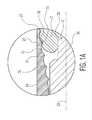
- FIG. 1Ais an enlarged view of the coupling between the tissue protection sleeve, bone screw head, and screw driver of the present invention as shown in FIG. 1 ;
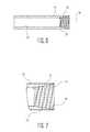
- FIG. 2is an isometric view of the bone screw of FIG. 1 ;
- FIG. 2Ais a side view of the screw of FIG. 2 ;
- FIG. 3is a view of the threaded head of the bone screw of FIG. 2 ;
- FIG. 4is a cross-sectional view of the bone screw of FIG. 2 ;
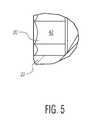
- FIG. 5is an enlarged view of the hex drive of the bone screw of FIG. 2 ;
- FIG. 6is a cross-sectional view of the tissue protection sleeve of the present invention.
- FIG. 7is an enlarged view of the distal end of the tissue protection sleeve of the present invention.
- FIGS. 8A and 8B(in cross-section) show an alternate distal end for the tissue protection sleeve wherein the distal end of the sleeve can flex with respect to the axis of the bone screw.
- the screw insertion systemincludes a screw 12 , a sleeve or holder 14 for connecting to screw 12 , and a driver 16 with shaft 17 .
- screw 12is a bone screw
- sleeve 14is a tissue protection sleeve used for inserting the threaded screw into a bone plate or bone nail (not shown).
- Driver 16can be any standard screw driver having a leading distal end with a standard screw drive 18 , such as a hex drive or a Torx® drive.
- Drive 18is adapted to engage a socket or recess 20 in a head 22 of screw 12 .
- screw 12has a head 22 with threads 23 and a threaded shaft 25 .
- Head 32is adapted engage the threads 26 of internal surface 24 at a distal end of tissue protection sleeve 14 .
- Threads 23taper inwardly on moving away in a proximal direction from the bone screw threads on shaft 25 .
- FIG. 1Athere is an enlarged view of the engagement between tissue protection sleeve 14 , screw head 22 , driver 16 and socket 20 .
- the distal end 24 of sleeve 14includes a plurality of threads along a threaded inner diameter 26 .
- inner diameter threads 26taper outwardly from central axis 28 of the bone screw sleeve 14 preferably in a conical manner.
- the distal threaded distal end inner surface 24 of sleeve 14preferably includes flat root areas 30 and flat crests 31 along the outwardly tapered surface of inner surface 26 of sleeve 14 .
- Screw head 22has rounded roots 33 and flat crests 35 .
- the outer diameter 27 at the leading end of the sleeveis substantially equal to the largest thread diameter of head 22 which is located adjacent to shaft 25 . While the diameters do not have to be exactly equal a large step is to be avoided so that surrounding tissue is not irritated during insertion.
- bone screw 12with head 22 and shaft 25 with threads 32 .
- the threads 32 of bone screw 12include a helical thread adapted to engage bone and may or may not have a self-drilling feature 34 adjacent a distal tip 36 .
- the threads 32 of bone screw 12may be any typical threads used for bone screws.
- a transition area 37extends between the head 22 and shaft 25 .
- Sleeve 14has an inner diameter 52 which receives an outer surface of driver shaft 17 . These surfaces may be a close fit to permit sliding engagement.
- FIG. 3there is shown an enlarged view of head 22 which tapers outwardly from central axis 28 at an angle ⁇ .
- Angle ⁇is preferably 9 to 10° thus making the cone angle of the tapering head 18 to 20°.
- the head 22includes helical thread 40 which preferably has an arcuate root-shape 33 separated by a flattened crest 35 as best shown in FIG. 1A .
- the root 33may have a circular shape of, for example, a radius of 0.6 to 0.8 mm.
- the threaded depth from the crest 35 to the bottom of the root 33may be, for example, 0.14 mm.
- the threadsare preferably a double or triple lead thread, and are left-handed, whereas, the threads of the bone screw shaft are right-handed.
- the headhas an annular surface 48 facing the distal end of the screw (i.e. towards tip 36 )
- FIGS. 4 and 5there is shown a cross-section of bone screw 12 including the bone screw shaft 25 and in particular head 22 , which includes a hex socket 20 for receiving the drive end 18 of the screw driver 16 .
- FIG. 5shows the flat sides 42 of hex socket 20 .
- Socket 20is adapted to receive a standard hex drive from an Allen wrench or screw driver. A TORX® drive or other polygonal drive could be used.
- tissue protection sleeve 14including threaded distal end 24 including threaded inner diameter 26 , which tapers outwardly from centerline 28 .
- Threaded diameter 26tapers outwardly at the same angle that screw threads 23 are tapered inwardly towards the head free end i.e., for example, 10°.
- the entire distal opening of the sleevetapers outwardly on moving distally at an included angle of 20°.
- the threads 26as shown in FIG. 1A , have flat crests and flat roots. The crests are spaced such that they engage the deepest root area of circular or arcuate threads 33 . These thread shapes produce less friction so that the tissue protection sleeve may be more easily removed from the head of the screw after implantation.
- head 22includes a distally facing surface 37 which in FIG. 4 is annular planar surface 48 .
- Surface 48may be connected to screw shaft 25 by an arcuate portion 50 which, in the preferred embodiment, is concave.
- this connection portion 50could be convex and have a part-spherical shape around the entire circumference of the junction between shaft 25 and screw head 22 . This would allow for polyaxial movement of the screw as, for example, when implanted in a bone plate (not shown).
- the surgeonthreadably couples the sleeve or screw holder 14 to the head of 22 of screw 52 so that the outer diameter 27 is flush or nearly flush with the largest thread diameter of head 22 .
- the surgeonthen inserts the driver 16 through sleeve 14 into the drive 18 of screw 12 .
- Screw 12is then inserted into the bone.
- the sleeve 14can be removed by rotating an exposed end of sleeve 14 in the direction of screw rotation because of the opposite left and right threads on the bone screw head 22 and shaft 25 .
- the sleevemay have a smaller outer diameter (OD), for example 7 mm and have markings near the grip which indicate when to stop turning, it may also have slotted structures to allow for “gripping” even when screws are inserted in a non-axial fashion.
- ODouter diameter
- the distal end of sleeve 14can flex slightly when the screw axis is angled with respect to the sleeve axis.
- FIGS. 8A and 8Bwhich has a plurality of slots 200 spaced around the circumference of the tissue protection sleeve.
- the sleevemay have a larger OD, for example 9 mm.
- the reason for the larger diameter of 9 mmis that especially for axially stable screws such a larger diameter increases the contact area between the tool tip and screw head which respectively improves the tactile sensation for the operator. This is important as the operator needs to know and feel when to stop turning (when the screw head hits the bone surface). With the larger diameter the sleeve distal end will be larger than the screw head diameter by 1 to 2 mm.
Landscapes
- Health & Medical Sciences (AREA)
- Orthopedic Medicine & Surgery (AREA)
- Life Sciences & Earth Sciences (AREA)
- Surgery (AREA)
- Medical Informatics (AREA)
- General Health & Medical Sciences (AREA)
- Biomedical Technology (AREA)
- Heart & Thoracic Surgery (AREA)
- Nuclear Medicine, Radiotherapy & Molecular Imaging (AREA)
- Molecular Biology (AREA)
- Animal Behavior & Ethology (AREA)
- Engineering & Computer Science (AREA)
- Public Health (AREA)
- Veterinary Medicine (AREA)
- Neurology (AREA)
- Surgical Instruments (AREA)
- Portable Nailing Machines And Staplers (AREA)
- Dental Prosthetics (AREA)
- Injection Moulding Of Plastics Or The Like (AREA)
Abstract
Description
Claims (23)
Priority Applications (11)
| Application Number | Priority Date | Filing Date | Title |
|---|---|---|---|
| US15/399,233US10426535B2 (en) | 2017-01-05 | 2017-01-05 | Self-holding screw head |
| AU2017279730AAU2017279730B2 (en) | 2017-01-05 | 2017-12-21 | Self-holding screw head |
| CA2990073ACA2990073C (en) | 2017-01-05 | 2017-12-21 | Self-holding screw head |
| JP2017249270AJP6677704B2 (en) | 2017-01-05 | 2017-12-26 | Self-holding screw head |
| CN201810004463.3ACN108272500A (en) | 2017-01-05 | 2018-01-03 | Self-retaining head of screw |
| EP19206814.6AEP3636188B1 (en) | 2017-01-05 | 2018-01-04 | Self-holding screw head |
| EP18150311.1AEP3345561B1 (en) | 2017-01-05 | 2018-01-04 | Self-holding screw head |
| ES18150311TES2769233T3 (en) | 2017-01-05 | 2018-01-04 | Self-supporting screw head |
| US16/518,110US11432861B2 (en) | 2017-01-05 | 2019-07-22 | Self-holding screw head |
| US17/851,311US11925399B2 (en) | 2017-01-05 | 2022-06-28 | Self-holding screw head |
| US18/433,805US12324614B2 (en) | 2017-01-05 | 2024-02-06 | Self-holding screw head |
Applications Claiming Priority (1)
| Application Number | Priority Date | Filing Date | Title |
|---|---|---|---|
| US15/399,233US10426535B2 (en) | 2017-01-05 | 2017-01-05 | Self-holding screw head |
Related Child Applications (1)
| Application Number | Title | Priority Date | Filing Date |
|---|---|---|---|
| US16/518,110ContinuationUS11432861B2 (en) | 2017-01-05 | 2019-07-22 | Self-holding screw head |
Publications (2)
| Publication Number | Publication Date |
|---|---|
| US20180185076A1 US20180185076A1 (en) | 2018-07-05 |
| US10426535B2true US10426535B2 (en) | 2019-10-01 |
Family
ID=60937615
Family Applications (4)
| Application Number | Title | Priority Date | Filing Date |
|---|---|---|---|
| US15/399,233Active2037-10-08US10426535B2 (en) | 2017-01-05 | 2017-01-05 | Self-holding screw head |
| US16/518,110Active2038-03-01US11432861B2 (en) | 2017-01-05 | 2019-07-22 | Self-holding screw head |
| US17/851,311ActiveUS11925399B2 (en) | 2017-01-05 | 2022-06-28 | Self-holding screw head |
| US18/433,805ActiveUS12324614B2 (en) | 2017-01-05 | 2024-02-06 | Self-holding screw head |
Family Applications After (3)
| Application Number | Title | Priority Date | Filing Date |
|---|---|---|---|
| US16/518,110Active2038-03-01US11432861B2 (en) | 2017-01-05 | 2019-07-22 | Self-holding screw head |
| US17/851,311ActiveUS11925399B2 (en) | 2017-01-05 | 2022-06-28 | Self-holding screw head |
| US18/433,805ActiveUS12324614B2 (en) | 2017-01-05 | 2024-02-06 | Self-holding screw head |
Country Status (7)
| Country | Link |
|---|---|
| US (4) | US10426535B2 (en) |
| EP (2) | EP3345561B1 (en) |
| JP (1) | JP6677704B2 (en) |
| CN (1) | CN108272500A (en) |
| AU (1) | AU2017279730B2 (en) |
| CA (1) | CA2990073C (en) |
| ES (1) | ES2769233T3 (en) |
Cited By (12)
| Publication number | Priority date | Publication date | Assignee | Title |
|---|---|---|---|---|
| US20210251727A1 (en)* | 2018-08-31 | 2021-08-19 | Hardlock Industry Co., Ltd. | Screw-fastening assembly having anti-loosening capabilities |
| US20210393394A1 (en)* | 2020-06-23 | 2021-12-23 | Thomas Zink | Multiple drive interference screw system and device |
| US11291477B1 (en) | 2021-05-04 | 2022-04-05 | Warsaw Orthopedic, Inc. | Dorsal adjusting implant and methods of use |
| US11325231B2 (en)* | 2019-11-22 | 2022-05-10 | DePuy Synthes Products, Inc. | Self-retaining screwdriver with engaging tip feature |
| US11395685B2 (en)* | 2018-07-03 | 2022-07-26 | Andrea Urizzi | Orthopedic kit |
| US11432848B1 (en) | 2021-05-12 | 2022-09-06 | Warsaw Orthopedic, Inc. | Top loading quick lock construct |
| US11627998B2 (en) | 2020-12-11 | 2023-04-18 | Warsaw Orthopedic, Inc. | Head position and driver combination instrument |
| US11679005B1 (en)* | 2022-05-26 | 2023-06-20 | Spinal Simplicity, Llc | Implant removal tool |
| US11712270B2 (en) | 2021-05-17 | 2023-08-01 | Warsaw Orthopedic, Inc. | Quick lock clamp constructs and associated methods |
| US11957391B2 (en) | 2021-11-01 | 2024-04-16 | Warsaw Orthopedic, Inc. | Bone screw having an overmold of a shank |
| US12004782B2 (en) | 2020-03-26 | 2024-06-11 | Warsaw Orthopedic, Inc. | Instrument for locking orthopedic screws |
| US12121268B2 (en) | 2021-07-07 | 2024-10-22 | Globus Medical, Inc. | Modular orthopedic implants, instruments, and navigation methods |
Families Citing this family (3)
| Publication number | Priority date | Publication date | Assignee | Title |
|---|---|---|---|---|
| CN113473918B (en)* | 2018-09-14 | 2024-10-01 | 博恩医疗器械股份有限公司 | Orthopedic bone screw |
| CN109259845A (en)* | 2018-10-16 | 2019-01-25 | 创辉医疗器械江苏有限公司 | A kind of the dynamic lock screw and its processing method of annular empty avoiding |
| US11517362B2 (en)* | 2020-04-30 | 2022-12-06 | DePuy Synthes Products, Inc. | Self-retaining screw and screwdriver |
Citations (39)
| Publication number | Priority date | Publication date | Assignee | Title |
|---|---|---|---|---|
| US1287203A (en) | 1918-03-26 | 1918-12-10 | Nat Tube Co | Drill-tube section. |
| US1364478A (en) | 1919-10-11 | 1921-01-04 | Nat Tube Co | Drill-tube |
| US1973848A (en) | 1932-05-26 | 1934-09-18 | Peter J Duffy | Flush joint drill stem |
| US2704170A (en) | 1953-06-08 | 1955-03-15 | Ray Roland | Teapot |
| SU827050A1 (en) | 1979-03-26 | 1981-05-07 | Казанский Научно-Исследовательскийинститут Травматологии И Ортопедии | Osteosynthesis device |
| US4478113A (en) | 1982-05-03 | 1984-10-23 | Berneiser Herwig M | Tool for aiding in thread connecting a spark plug or other object in place |
| US4541139A (en) | 1983-06-03 | 1985-09-17 | The Drackett Company | Broom shroud |
| EP0387392A2 (en) | 1989-03-17 | 1990-09-19 | Donald R. Huene | Bone screw fixation assembly, bone screw therefor and method of fixation |
| US5143411A (en) | 1986-07-18 | 1992-09-01 | Watts John Dawson | Threaded tubular connection |
| USRE34467E (en) | 1983-04-29 | 1993-12-07 | The Hydril Company | Tubular connection |
| WO1994020039A1 (en) | 1993-03-11 | 1994-09-15 | Dietmar Pennig | Screw for securing an intramedullary nail |
| US5536127A (en) | 1994-10-13 | 1996-07-16 | Pennig; Dietmar | Headed screw construction for use in fixing the position of an intramedullary nail |
| US5737981A (en) | 1995-09-20 | 1998-04-14 | Hildebrand; David Lewis | Removal device for threaded connecting devices |
| US6017177A (en)* | 1997-10-06 | 2000-01-25 | Mcgard, Inc. | Multi-tier security fastener |
| US6030162A (en) | 1998-12-18 | 2000-02-29 | Acumed, Inc. | Axial tension screw |
| US6102642A (en)* | 1997-02-20 | 2000-08-15 | Yamahiro Co., Ltd. | Screw head |
| US6267025B1 (en) | 1998-11-20 | 2001-07-31 | Sulzer Spine-Tech, Inc. | Broken pedicle screw extractor |
| US6337142B2 (en) | 1997-07-02 | 2002-01-08 | Stryker Trauma Gmbh | Elongate element for transmitting forces |
| US6565573B1 (en) | 2001-04-16 | 2003-05-20 | Smith & Nephew, Inc. | Orthopedic screw and method of use |
| US6599290B2 (en) | 2001-04-17 | 2003-07-29 | Ebi, L.P. | Anterior cervical plating system and associated method |
| US20060025773A1 (en) | 2001-12-04 | 2006-02-02 | Yan Yevmenenko | Headless compression screw with integrated reduction-compression instrument |
| US20060149264A1 (en) | 2004-12-20 | 2006-07-06 | Castaneda Javier E | Screw locking systems for bone plates |
| US7476228B2 (en) | 2002-10-11 | 2009-01-13 | Abdou M Samy | Distraction screw for skeletal surgery and method of use |
| US7798755B2 (en) | 2005-04-20 | 2010-09-21 | Erwin Tomm | Threaded connector with interlock |
| US7887547B2 (en) | 2000-06-26 | 2011-02-15 | Stryker Spine | Bone screw retaining system |
| US20110060373A1 (en)* | 2009-09-09 | 2011-03-10 | Russell Thomas A | Bone screws and methods of use thereof |
| JP2011161583A (en) | 2010-02-12 | 2011-08-25 | Sumitomo Electric Hardmetal Corp | Head attaching and detaching type cutting tool |
| US20120022603A1 (en)* | 2010-07-20 | 2012-01-26 | X-Spine Systems, Inc. | Spinal facet compression screw with variable pitch thread zones and buttress head |
| US8273113B2 (en) | 2001-12-04 | 2012-09-25 | Synthes Usa, Llc | Bone screw |
| US20130011215A1 (en)* | 2010-03-15 | 2013-01-10 | Atomic22 Limited | Security fastener |
| US20130226239A1 (en) | 2012-02-23 | 2013-08-29 | Moti Altarac | Facet screw and method for spinal stabilization |
| US20140018862A1 (en)* | 2012-06-27 | 2014-01-16 | DePuy Synthes Products, LLC | Variable angle bone fixation device |
| US20140114362A1 (en)* | 2009-04-03 | 2014-04-24 | Stryker Trauma Gmbh | Sonic screw |
| US20140236245A1 (en)* | 2013-02-20 | 2014-08-21 | Stryker Trauma Sa | Screw thread with flattened peaks |
| US20140236242A1 (en) | 2012-01-25 | 2014-08-21 | James C. Robinson | Fenestrated bone screws and methods of bone fastening and stabilization |
| US8992581B2 (en) | 2003-09-29 | 2015-03-31 | Smith & Nephew, Inc. | Bone plate and bone plate assemblies including polyaxial fasteners |
| US20150362100A1 (en) | 2014-06-13 | 2015-12-17 | Schlumberger Technology Corporation | Rotary Shouldered Connections and Thread Design |
| US9339315B2 (en) | 2010-03-08 | 2016-05-17 | Stryker European Holdings I, Llc | Bone fixation system with curved profile threads |
| US20160151101A1 (en) | 2013-07-12 | 2016-06-02 | Tama Medical Co., LTD. | Medical screw, and extraction jig for medical screw |
Family Cites Families (30)
| Publication number | Priority date | Publication date | Assignee | Title |
|---|---|---|---|---|
| US2723694A (en) | 1953-01-23 | 1955-11-15 | James P Ross | Screw driver attachment |
| US4455898A (en) | 1982-06-07 | 1984-06-26 | Marbourg Jr Edgar F | Tool for capture, control and manipulation of threaded fasteners |
| FR2704170B1 (en)* | 1993-04-20 | 1995-07-13 | Medinov Sa | SCREWDRIVER WITH A COUPLING MEANS FOR A SCREW OR THE LIKE. |
| DE29506731U1 (en) | 1995-04-20 | 1995-06-22 | Voith Sulzer Papiermaschinen GmbH, 89522 Heidenheim | Application work for coating a running web, in particular made of paper or cardboard |
| EP0888754A1 (en)* | 1997-07-03 | 1999-01-07 | Acromed Corporation | Osteosynthetic Fastener |
| US6554834B1 (en)* | 1999-10-07 | 2003-04-29 | Stryker Spine | Slotted head pedicle screw assembly |
| SE516862C2 (en)* | 2000-07-14 | 2002-03-12 | Allgon Ab | Reconciliation screw device and method and resonator |
| US7833250B2 (en)* | 2004-11-10 | 2010-11-16 | Jackson Roger P | Polyaxial bone screw with helically wound capture connection |
| US6974460B2 (en)* | 2001-09-14 | 2005-12-13 | Stryker Spine | Biased angulation bone fixation assembly |
| US6875215B2 (en)* | 2002-02-15 | 2005-04-05 | John Stanley Taras | Distraction pin for fracture fixation |
| US7354442B2 (en)* | 2003-05-05 | 2008-04-08 | Warsaw Orthopedic, Inc. | Bone anchor and methods of using the same |
| US7708766B2 (en)* | 2003-08-11 | 2010-05-04 | Depuy Spine, Inc. | Distraction screw |
| KR200443999Y1 (en)* | 2006-10-13 | 2009-04-02 | 주식회사 솔고 바이오메디칼 | Multiaxial Spine Fixation Device |
| US20080147128A1 (en)* | 2006-12-15 | 2008-06-19 | Zimmer Technology, Inc. | Cannulated bone screw and cannulated driver for the implantation thereof |
| AU2008318657A1 (en) | 2007-10-30 | 2009-05-07 | Synthes Gmbh | Variable angle locked bone plate |
| BRPI0818869A2 (en)* | 2008-07-29 | 2015-05-05 | Synthes Gmbh | Plate for fixation on a target bone part to be treated, and, method. |
| US8241341B2 (en)* | 2009-03-20 | 2012-08-14 | Spinal Usa, Inc. | Pedicle screws and methods of using the same |
| US10390867B2 (en)* | 2009-09-18 | 2019-08-27 | Biomet C.V. | Bone plate system and method |
| DE102009049168A1 (en)* | 2009-10-12 | 2011-04-28 | Normed Medizin-Technik Gmbh | Bone screw and system |
| JP5756118B2 (en)* | 2009-11-17 | 2015-07-29 | シンセス ゲゼルシャフト ミット ベシュレンクテル ハフツングSynthes Gmbh | Fixed support pin with variable angle |
| US8945193B2 (en)* | 2010-07-20 | 2015-02-03 | X-Spine Systems, Inc. | Minimally invasive spinal facet compression screw and system for bone joint fusion and fixation |
| CN201759663U (en)* | 2010-08-31 | 2011-03-16 | 常州迪恩医疗器械有限公司 | Locking type anterior cervical plate system |
| US8459155B2 (en) | 2010-09-03 | 2013-06-11 | Smith & Nephew, Inc. | Modified fastener and insertion tool |
| CN102465712B (en)* | 2010-11-15 | 2015-01-28 | 湖南汉寿中煤科技有限公司 | Drilling-cutting-linked coal layer gas drainage and outburst prevention system and method based on ultra-long drilling and high-pressure water jetting |
| DE102010055433B4 (en)* | 2010-12-10 | 2014-07-24 | Celgen Ag | Bone screw and device for bone distraction |
| US9078740B2 (en)* | 2013-01-21 | 2015-07-14 | Howmedica Osteonics Corp. | Instrumentation and method for positioning and securing a graft |
| US10166055B2 (en)* | 2014-05-16 | 2019-01-01 | Biomet C.V. | Method and apparatus for bone fixation |
| US11045210B2 (en)* | 2014-06-26 | 2021-06-29 | DePuy Synthes Products, Inc. | Flexible spinal driver or drill with a malleable core, and/or fixed core radius |
| CN205019151U (en)* | 2015-09-30 | 2016-02-10 | 浙江科惠医疗器械股份有限公司 | Universal locking device of locking coaptation board |
| US10531905B2 (en)* | 2016-04-19 | 2020-01-14 | Globus Medical, Inc. | Implantable compression screws |
- 2017
- 2017-01-05USUS15/399,233patent/US10426535B2/enactiveActive
- 2017-12-21CACA2990073Apatent/CA2990073C/enactiveActive
- 2017-12-21AUAU2017279730Apatent/AU2017279730B2/enactiveActive
- 2017-12-26JPJP2017249270Apatent/JP6677704B2/enactiveActive
- 2018
- 2018-01-03CNCN201810004463.3Apatent/CN108272500A/enactivePending
- 2018-01-04EPEP18150311.1Apatent/EP3345561B1/enactiveActive
- 2018-01-04ESES18150311Tpatent/ES2769233T3/enactiveActive
- 2018-01-04EPEP19206814.6Apatent/EP3636188B1/enactiveActive
- 2019
- 2019-07-22USUS16/518,110patent/US11432861B2/enactiveActive
- 2022
- 2022-06-28USUS17/851,311patent/US11925399B2/enactiveActive
- 2024
- 2024-02-06USUS18/433,805patent/US12324614B2/enactiveActive
Patent Citations (50)
| Publication number | Priority date | Publication date | Assignee | Title |
|---|---|---|---|---|
| US1287203A (en) | 1918-03-26 | 1918-12-10 | Nat Tube Co | Drill-tube section. |
| US1364478A (en) | 1919-10-11 | 1921-01-04 | Nat Tube Co | Drill-tube |
| US1973848A (en) | 1932-05-26 | 1934-09-18 | Peter J Duffy | Flush joint drill stem |
| US2704170A (en) | 1953-06-08 | 1955-03-15 | Ray Roland | Teapot |
| SU827050A1 (en) | 1979-03-26 | 1981-05-07 | Казанский Научно-Исследовательскийинститут Травматологии И Ортопедии | Osteosynthesis device |
| US4478113A (en) | 1982-05-03 | 1984-10-23 | Berneiser Herwig M | Tool for aiding in thread connecting a spark plug or other object in place |
| USRE34467E (en) | 1983-04-29 | 1993-12-07 | The Hydril Company | Tubular connection |
| US4541139A (en) | 1983-06-03 | 1985-09-17 | The Drackett Company | Broom shroud |
| US5143411A (en) | 1986-07-18 | 1992-09-01 | Watts John Dawson | Threaded tubular connection |
| EP0387392A2 (en) | 1989-03-17 | 1990-09-19 | Donald R. Huene | Bone screw fixation assembly, bone screw therefor and method of fixation |
| US4963144A (en) | 1989-03-17 | 1990-10-16 | Huene Donald R | Bone screw fixation assembly, bone screw therefor and method of fixation |
| US5375956A (en) | 1993-03-11 | 1994-12-27 | Pennig; Dietmar | Head screw construction for use in fixing the position of an intramedullary nail |
| JPH07505567A (en) | 1993-03-11 | 1995-06-22 | ペニヒ ディートマル | Screws for fixing intramedullary nails |
| WO1994020039A1 (en) | 1993-03-11 | 1994-09-15 | Dietmar Pennig | Screw for securing an intramedullary nail |
| US5536127A (en) | 1994-10-13 | 1996-07-16 | Pennig; Dietmar | Headed screw construction for use in fixing the position of an intramedullary nail |
| US5737981A (en) | 1995-09-20 | 1998-04-14 | Hildebrand; David Lewis | Removal device for threaded connecting devices |
| US6102642A (en)* | 1997-02-20 | 2000-08-15 | Yamahiro Co., Ltd. | Screw head |
| US6337142B2 (en) | 1997-07-02 | 2002-01-08 | Stryker Trauma Gmbh | Elongate element for transmitting forces |
| US6017177A (en)* | 1997-10-06 | 2000-01-25 | Mcgard, Inc. | Multi-tier security fastener |
| US6267025B1 (en) | 1998-11-20 | 2001-07-31 | Sulzer Spine-Tech, Inc. | Broken pedicle screw extractor |
| US6030162A (en) | 1998-12-18 | 2000-02-29 | Acumed, Inc. | Axial tension screw |
| US7887547B2 (en) | 2000-06-26 | 2011-02-15 | Stryker Spine | Bone screw retaining system |
| US6565573B1 (en) | 2001-04-16 | 2003-05-20 | Smith & Nephew, Inc. | Orthopedic screw and method of use |
| US6599290B2 (en) | 2001-04-17 | 2003-07-29 | Ebi, L.P. | Anterior cervical plating system and associated method |
| US8540726B2 (en) | 2001-12-04 | 2013-09-24 | DePuy Synthes Products, LLC | Headless compression screw with integrated reduction-compression instrument |
| US8216243B2 (en) | 2001-12-04 | 2012-07-10 | Synthes Usa, Llc | Headless compression screw with integrated reduction-compression instrument |
| US9113976B2 (en) | 2001-12-04 | 2015-08-25 | DePuy Synthes Products, Inc. | Headless compression screw with integrated reduction-compression instrument |
| US20060025773A1 (en) | 2001-12-04 | 2006-02-02 | Yan Yevmenenko | Headless compression screw with integrated reduction-compression instrument |
| US8460349B2 (en) | 2001-12-04 | 2013-06-11 | Synthes Usa, Llc | Bone screw |
| US8273113B2 (en) | 2001-12-04 | 2012-09-25 | Synthes Usa, Llc | Bone screw |
| US7476228B2 (en) | 2002-10-11 | 2009-01-13 | Abdou M Samy | Distraction screw for skeletal surgery and method of use |
| US8992581B2 (en) | 2003-09-29 | 2015-03-31 | Smith & Nephew, Inc. | Bone plate and bone plate assemblies including polyaxial fasteners |
| US8187309B2 (en) | 2004-12-20 | 2012-05-29 | Depuy Products, Inc. | Screw locking systems for bone plates |
| US20060149264A1 (en) | 2004-12-20 | 2006-07-06 | Castaneda Javier E | Screw locking systems for bone plates |
| US7798755B2 (en) | 2005-04-20 | 2010-09-21 | Erwin Tomm | Threaded connector with interlock |
| US20140114362A1 (en)* | 2009-04-03 | 2014-04-24 | Stryker Trauma Gmbh | Sonic screw |
| US20110060373A1 (en)* | 2009-09-09 | 2011-03-10 | Russell Thomas A | Bone screws and methods of use thereof |
| US9333018B2 (en) | 2009-09-09 | 2016-05-10 | Innovision, Inc. | Bone screws and methods of use thereof |
| JP2011161583A (en) | 2010-02-12 | 2011-08-25 | Sumitomo Electric Hardmetal Corp | Head attaching and detaching type cutting tool |
| US9339315B2 (en) | 2010-03-08 | 2016-05-17 | Stryker European Holdings I, Llc | Bone fixation system with curved profile threads |
| US20130011215A1 (en)* | 2010-03-15 | 2013-01-10 | Atomic22 Limited | Security fastener |
| US20120022603A1 (en)* | 2010-07-20 | 2012-01-26 | X-Spine Systems, Inc. | Spinal facet compression screw with variable pitch thread zones and buttress head |
| US20140236242A1 (en) | 2012-01-25 | 2014-08-21 | James C. Robinson | Fenestrated bone screws and methods of bone fastening and stabilization |
| US20130226239A1 (en) | 2012-02-23 | 2013-08-29 | Moti Altarac | Facet screw and method for spinal stabilization |
| US20140018862A1 (en)* | 2012-06-27 | 2014-01-16 | DePuy Synthes Products, LLC | Variable angle bone fixation device |
| US9387022B2 (en) | 2012-06-27 | 2016-07-12 | DePuy Synthes Products, Inc. | Variable angle bone fixation device |
| US9107711B2 (en) | 2013-02-20 | 2015-08-18 | Stryker Trauma Sa | Screw thread with flattened peaks |
| US20140236245A1 (en)* | 2013-02-20 | 2014-08-21 | Stryker Trauma Sa | Screw thread with flattened peaks |
| US20160151101A1 (en) | 2013-07-12 | 2016-06-02 | Tama Medical Co., LTD. | Medical screw, and extraction jig for medical screw |
| US20150362100A1 (en) | 2014-06-13 | 2015-12-17 | Schlumberger Technology Corporation | Rotary Shouldered Connections and Thread Design |
Non-Patent Citations (1)
| Title |
|---|
| European Search Report from EP Application No. 2018150311, dated Mar. 21, 2018. |
Cited By (12)
| Publication number | Priority date | Publication date | Assignee | Title |
|---|---|---|---|---|
| US11395685B2 (en)* | 2018-07-03 | 2022-07-26 | Andrea Urizzi | Orthopedic kit |
| US20210251727A1 (en)* | 2018-08-31 | 2021-08-19 | Hardlock Industry Co., Ltd. | Screw-fastening assembly having anti-loosening capabilities |
| US11325231B2 (en)* | 2019-11-22 | 2022-05-10 | DePuy Synthes Products, Inc. | Self-retaining screwdriver with engaging tip feature |
| US12004782B2 (en) | 2020-03-26 | 2024-06-11 | Warsaw Orthopedic, Inc. | Instrument for locking orthopedic screws |
| US20210393394A1 (en)* | 2020-06-23 | 2021-12-23 | Thomas Zink | Multiple drive interference screw system and device |
| US11627998B2 (en) | 2020-12-11 | 2023-04-18 | Warsaw Orthopedic, Inc. | Head position and driver combination instrument |
| US11291477B1 (en) | 2021-05-04 | 2022-04-05 | Warsaw Orthopedic, Inc. | Dorsal adjusting implant and methods of use |
| US11432848B1 (en) | 2021-05-12 | 2022-09-06 | Warsaw Orthopedic, Inc. | Top loading quick lock construct |
| US11712270B2 (en) | 2021-05-17 | 2023-08-01 | Warsaw Orthopedic, Inc. | Quick lock clamp constructs and associated methods |
| US12121268B2 (en) | 2021-07-07 | 2024-10-22 | Globus Medical, Inc. | Modular orthopedic implants, instruments, and navigation methods |
| US11957391B2 (en) | 2021-11-01 | 2024-04-16 | Warsaw Orthopedic, Inc. | Bone screw having an overmold of a shank |
| US11679005B1 (en)* | 2022-05-26 | 2023-06-20 | Spinal Simplicity, Llc | Implant removal tool |
Also Published As
| Publication number | Publication date |
|---|---|
| JP2018118037A (en) | 2018-08-02 |
| EP3636188A3 (en) | 2020-07-29 |
| AU2017279730B2 (en) | 2022-01-27 |
| CA2990073A1 (en) | 2018-07-05 |
| EP3636188B1 (en) | 2022-07-06 |
| EP3636188A2 (en) | 2020-04-15 |
| EP3345561A1 (en) | 2018-07-11 |
| AU2017279730A1 (en) | 2018-07-19 |
| US12324614B2 (en) | 2025-06-10 |
| US20180185076A1 (en) | 2018-07-05 |
| EP3345561B1 (en) | 2019-11-13 |
| CA2990073C (en) | 2020-03-10 |
| ES2769233T3 (en) | 2020-06-25 |
| CN108272500A (en) | 2018-07-13 |
| US20220323129A1 (en) | 2022-10-13 |
| US20190336187A1 (en) | 2019-11-07 |
| US20240238021A1 (en) | 2024-07-18 |
| US11925399B2 (en) | 2024-03-12 |
| JP6677704B2 (en) | 2020-04-08 |
| US11432861B2 (en) | 2022-09-06 |
Similar Documents
| Publication | Publication Date | Title |
|---|---|---|
| US11925399B2 (en) | Self-holding screw head | |
| US9339315B2 (en) | Bone fixation system with curved profile threads | |
| US7604643B2 (en) | Adjustable tool for cannulated fasteners | |
| EP2364657B1 (en) | Bone fixation system with curved profile threads | |
| US20070122764A1 (en) | Orthodontic bone screw | |
| US20070218750A1 (en) | Snap-off screw with recessed breakoff area | |
| JP2014512853A (en) | Implant system for bone fixation | |
| JP7650523B2 (en) | Compression nuts, systems and methods for treating bones - Patents.com | |
| CN113768604A (en) | Universal hollow locking screw | |
| CN216090736U (en) | Universal hollow locking screw | |
| CN211704796U (en) | Intramedullary nail and intramedullary nail internal fixation kit | |
| CN223403940U (en) | A hollow nail cable fixation device for patellar fracture | |
| CN217886172U (en) | Adapter assembly, adapter kit and implantation instrument | |
| HK1098658A (en) | Orthodontic bone screw |
Legal Events
| Date | Code | Title | Description |
|---|---|---|---|
| AS | Assignment | Owner name:STRYKER TRAUMA GMBH, GERMANY Free format text:ASSIGNMENT OF ASSIGNORS INTEREST;ASSIGNORS:ZANDER, NILS;WIELAND, MANFRED;REEL/FRAME:041662/0842 Effective date:20170214 | |
| AS | Assignment | Owner name:STRYKER EUROPEAN HOLDINGS I, LLC, MICHIGAN Free format text:ASSIGNMENT OF ASSIGNORS INTEREST;ASSIGNOR:STRYKER TRAUMA GMBH;REEL/FRAME:041683/0135 Effective date:20170221 | |
| STPP | Information on status: patent application and granting procedure in general | Free format text:NON FINAL ACTION MAILED | |
| STPP | Information on status: patent application and granting procedure in general | Free format text:NOTICE OF ALLOWANCE MAILED -- APPLICATION RECEIVED IN OFFICE OF PUBLICATIONS | |
| STPP | Information on status: patent application and granting procedure in general | Free format text:PUBLICATIONS -- ISSUE FEE PAYMENT RECEIVED | |
| STPP | Information on status: patent application and granting procedure in general | Free format text:AWAITING TC RESP, ISSUE FEE PAYMENT VERIFIED | |
| STPP | Information on status: patent application and granting procedure in general | Free format text:PUBLICATIONS -- ISSUE FEE PAYMENT VERIFIED | |
| STCF | Information on status: patent grant | Free format text:PATENTED CASE | |
| AS | Assignment | Owner name:STRYKER EUROPEAN HOLDINGS III, LLC, DELAWARE Free format text:NUNC PRO TUNC ASSIGNMENT;ASSIGNOR:STRYKER EUROPEAN HOLDINGS I, LLC;REEL/FRAME:056969/0771 Effective date:20210219 Owner name:STRYKER EUROPEAN OPERATIONS HOLDINGS LLC, MICHIGAN Free format text:CHANGE OF NAME;ASSIGNOR:STRYKER EUROPEAN HOLDINGS III, LLC;REEL/FRAME:056969/0893 Effective date:20190226 | |
| MAFP | Maintenance fee payment | Free format text:PAYMENT OF MAINTENANCE FEE, 4TH YEAR, LARGE ENTITY (ORIGINAL EVENT CODE: M1551); ENTITY STATUS OF PATENT OWNER: LARGE ENTITY Year of fee payment:4 | |
| AS | Assignment | Owner name:STRYKER EUROPEAN OPERATIONS HOLDINGS LLC, MICHIGAN Free format text:CHANGE OF ADDRESS;ASSIGNOR:STRYKER EUROPEAN OPERATIONS HOLDINGS LLC;REEL/FRAME:069730/0754 Effective date:20241217 |