US10426521B2 - Vertebral osteosynthesis equipment - Google Patents
Vertebral osteosynthesis equipmentDownload PDFInfo
- Publication number
- US10426521B2 US10426521B2US15/568,605US201615568605AUS10426521B2US 10426521 B2US10426521 B2US 10426521B2US 201615568605 AUS201615568605 AUS 201615568605AUS 10426521 B2US10426521 B2US 10426521B2
- Authority
- US
- United States
- Prior art keywords
- ring
- head
- engagement
- angular position
- anchor member
- Prior art date
- Legal status (The legal status is an assumption and is not a legal conclusion. Google has not performed a legal analysis and makes no representation as to the accuracy of the status listed.)
- Active, expires
Links
- 238000007373indentationMethods0.000claimsdescription13
- 238000000034methodMethods0.000claimsdescription9
- 238000004873anchoringMethods0.000claimsdescription4
- 238000004519manufacturing processMethods0.000claimsdescription4
- 241000722921Tulipa gesnerianaSpecies0.000abstractdescription4
- 238000012937correctionMethods0.000description21
- 238000013459approachMethods0.000description8
- 238000000926separation methodMethods0.000description6
- 230000005540biological transmissionEffects0.000description4
- 238000002788crimpingMethods0.000description3
- 230000000903blocking effectEffects0.000description2
- 238000007796conventional methodMethods0.000description2
- 230000002093peripheral effectEffects0.000description2
- 238000003466weldingMethods0.000description2
- 238000005452bendingMethods0.000description1
- 230000007850degenerationEffects0.000description1
- 230000008030eliminationEffects0.000description1
- 238000003379elimination reactionMethods0.000description1
- 238000003780insertionMethods0.000description1
- 230000037431insertionEffects0.000description1
- 230000000717retained effectEffects0.000description1
Images


Classifications
- A—HUMAN NECESSITIES
- A61—MEDICAL OR VETERINARY SCIENCE; HYGIENE
- A61B—DIAGNOSIS; SURGERY; IDENTIFICATION
- A61B17/00—Surgical instruments, devices or methods
- A61B17/56—Surgical instruments or methods for treatment of bones or joints; Devices specially adapted therefor
- A61B17/58—Surgical instruments or methods for treatment of bones or joints; Devices specially adapted therefor for osteosynthesis, e.g. bone plates, screws or setting implements
- A61B17/68—Internal fixation devices, including fasteners and spinal fixators, even if a part thereof projects from the skin
- A61B17/70—Spinal positioners or stabilisers, e.g. stabilisers comprising fluid filler in an implant
- A61B17/7001—Screws or hooks combined with longitudinal elements which do not contact vertebrae
- A61B17/7035—Screws or hooks, wherein a rod-clamping part and a bone-anchoring part can pivot relative to each other
- A61B17/7037—Screws or hooks, wherein a rod-clamping part and a bone-anchoring part can pivot relative to each other wherein pivoting is blocked when the rod is clamped
- A—HUMAN NECESSITIES
- A61—MEDICAL OR VETERINARY SCIENCE; HYGIENE
- A61B—DIAGNOSIS; SURGERY; IDENTIFICATION
- A61B17/00—Surgical instruments, devices or methods
- A61B17/56—Surgical instruments or methods for treatment of bones or joints; Devices specially adapted therefor
- A61B17/58—Surgical instruments or methods for treatment of bones or joints; Devices specially adapted therefor for osteosynthesis, e.g. bone plates, screws or setting implements
- A61B17/68—Internal fixation devices, including fasteners and spinal fixators, even if a part thereof projects from the skin
- A61B17/70—Spinal positioners or stabilisers, e.g. stabilisers comprising fluid filler in an implant
- A61B17/7001—Screws or hooks combined with longitudinal elements which do not contact vertebrae
- A61B17/7032—Screws or hooks with U-shaped head or back through which longitudinal rods pass
- A—HUMAN NECESSITIES
- A61—MEDICAL OR VETERINARY SCIENCE; HYGIENE
- A61B—DIAGNOSIS; SURGERY; IDENTIFICATION
- A61B17/00—Surgical instruments, devices or methods
- A61B17/56—Surgical instruments or methods for treatment of bones or joints; Devices specially adapted therefor
- A61B17/58—Surgical instruments or methods for treatment of bones or joints; Devices specially adapted therefor for osteosynthesis, e.g. bone plates, screws or setting implements
- A61B17/68—Internal fixation devices, including fasteners and spinal fixators, even if a part thereof projects from the skin
- A61B17/70—Spinal positioners or stabilisers, e.g. stabilisers comprising fluid filler in an implant
- A61B17/7001—Screws or hooks combined with longitudinal elements which do not contact vertebrae
- A61B17/7035—Screws or hooks, wherein a rod-clamping part and a bone-anchoring part can pivot relative to each other
- A—HUMAN NECESSITIES
- A61—MEDICAL OR VETERINARY SCIENCE; HYGIENE
- A61B—DIAGNOSIS; SURGERY; IDENTIFICATION
- A61B17/00—Surgical instruments, devices or methods
- A61B17/56—Surgical instruments or methods for treatment of bones or joints; Devices specially adapted therefor
- A61B17/58—Surgical instruments or methods for treatment of bones or joints; Devices specially adapted therefor for osteosynthesis, e.g. bone plates, screws or setting implements
- A61B17/68—Internal fixation devices, including fasteners and spinal fixators, even if a part thereof projects from the skin
- A61B17/84—Fasteners therefor or fasteners being internal fixation devices
- A61B17/86—Pins or screws or threaded wires; nuts therefor
- A61B17/8685—Pins or screws or threaded wires; nuts therefor comprising multiple separate parts
- A—HUMAN NECESSITIES
- A61—MEDICAL OR VETERINARY SCIENCE; HYGIENE
- A61B—DIAGNOSIS; SURGERY; IDENTIFICATION
- A61B17/00—Surgical instruments, devices or methods
- A61B2017/00526—Methods of manufacturing
Definitions
- the present inventionrelates to a vertebral osteosynthesis equipment. It also relates to a method for manufacturing an anchor member comprised by this equipment.
- vertebral osteosynthesis equipmentcomprising connecting bars intended to connect several vertebrae to be treated to one another and anchor members (pedicle screws and/or laminar hooks) making it possible to connect these bars to the vertebrae.
- anchor membersprosthetic screws and/or laminar hooks
- the barsare curved according to the desired correction of the position of the vertebrae; if necessary, two adjacent anchor members connected to a same bar can be brought closer together or further apart before complete immobilization of the anchor members relative to the bar, to reduce a curvature of the spine in the frontal plane.
- At least one anchor membercan be of the so-called “tulip” type, i.e., comprising a wider head that forms an engagement duct of the connecting bar, the axis of this duct generally being secant to the axis of this head.
- This ductis closed, after placement of the connecting bar therein, by a threaded member screwed in the head.
- the body of the anchor membercan be in the form of a threaded rod intended to be screwed in the resected pedicle of a vertebra or in the form of a hook intended to be inserted behind the lamina of a vertebra.
- the anchor membercan be “monoaxial”, i.e., with said head secured to the body, or “polyaxial”, i.e., with said head articulated relative to said body. This articulation is in particular done by arranging a spherical part or sphere portion at the proximal end of said body and arranging, at the base of the head, in the bottom of said housing, a hole for the engagement of the body and a seat for articulated reception of said spherical part or sphere portion.
- the anchor membersare placed on the vertebrae, then the connecting bar(s) are curved depending on the repositioning of the vertebrae to be obtained, then these bars are placed in the different engagement ducts formed by the heads of the anchor members, and the threaded members are placed on these heads to retain the bars in said engagement duct; a movement of two adjacent anchor members connected to a same bar can be done at this stage, to bring the two vertebrae closer together or further apart on one side; once this corrections is done, the threaded members are tightened so as to immobilize the bars relative to said heads.
- the monoaxial anchor membershave the advantage of perfectly transmitting to the vertebrae the corrections imposed by the curvature of the bar(s) and the separating or approach corrections of two vertebrae; they have the major drawback, however, of making it difficult to engage a bar in the duct formed by the heads of the anchor members.
- Patent application publications Nos. US 2010/036417 A1 and US 2007/093832 A1describe pieces of equipment not making it possible to resolve the aforementioned drawbacks.
- the present inventiontherefore precisely aims to provide vertebral osteosynthesis equipment resolving the aforementioned drawbacks, i.e., allowing for transmission to the vertebrae of the corrections required by the curvature of the connecting bar(s) and the separation or approach corrections of two vertebrae, but without making it difficult to engage a bar in the duct formed by the heads of the anchor members.
- this equipmentcomprises:
- At least one connecting barhaving a length such that it is capable to span several vertebrae to be treated
- anchor memberhaving an anchoring portion for anchoring on a vertebra be treated, of the “tulip” type, i.e., comprising a body and a head that forms an engagement duct for the connecting bar, this duct being closed, after placement of the connecting bar therein, by a stop member capable to be screwed on the head;
- the anchor memberis of the so-called “polyaxial” type, i.e., with said head articulated relative to said body;
- the headforms, on its side turned toward the body, outside said duct, an articulation portion including a completely or partially spherical surface, and forms thereon a distal bearing surface;
- the bodyforms an articulation cavity for receiving said completely or partially spherical surface of the articulation portion, this articulation cavity being defined by a bearing wall outwardly having a partially spherical shape;
- the anchor memberincludes a ring located between the distal bearing surface formed by the head and the bearing wall comprised by the body, this ring having a partially spherical recessed surface for bearing against said bearing wall and being angularly mobile relative to the head;
- the ring and said bearing surfacecomprise inter-engagement means
- the ringhas an axis and is pivotable relative to the head about this axis;
- the headhas an axis and the inter-engagement means, in a first angular position of the ring, have a first inter-engagement position in which the ring is placed in a first position along the axis of the head, in which play exists between the ring and said bearing wall, such that the head is movable, in an articulated manner, relative to the body;
- the inter-engagement meanshave, in a second angular position of the ring, a second inter-engagement position in which they position and maintain the ring in a second position along the axis of the head, in which said play is eliminated and the ring presses against said bearing wall, such that the head is made immobile, or substantially immobile, relative to the body;
- the ringcomprises movement means for its pivoting movement, located angularly away from the openings by which said engagement duct emerges outside the head, such that the ring can be pivoted, by these movement means, even when a connecting bar is placed in said engagement duct.
- the anchor member of the equipment according to the inventionthus makes it possible at will, by pivoting the ring, to allow the polyaxiality of the head relative to the body to exist or to eliminate this polyaxiality.
- the anchor memberis placed on a vertebra, then, the ring being in said first angular position allowing the polyaxiality, the bar is placed in said engagement duct.
- the polyaxiality of the headfacilitates the placement of the bar in the engagement duct.
- the stop memberis next placed on the head without tightening so that the anchor member is still capable to slide along the bar.
- the placement of the barmakes it possible to bring the vertebrae into a correction position, which is, however, slightly lessened by the polyaxial nature of the anchor member; the vertebrae are then brought into a desired complete correction position, then the ring is pivoted to said second angular position, eliminating the polyaxiality.
- a separation or approach of the anchor member and another adjacent anchor membercan then be done if necessary, so as to correct the position of the two vertebrae in which these anchor members are implanted. Once this correction is done, the stop member is tightened so as to immobilize the anchor member relative to the bar in the obtained correction position.
- the inventionprovides equipment resolving the drawbacks of the equipment according to the prior art, i.e., allowing perfect transmission to the vertebrae of the corrections imposed by the curvature of the connecting bar(s) and the separation or approach corrections of two vertebrae, but without making it difficult to engage a bar in the ducts formed by the heads of the anchor members.
- the headcomprises said articulation portion
- the bodycomprises said bearing wall
- the inter-engagement meansare arranged on the ring and on said bearing surface comprised by the head.
- the inventionencompasses the alternative embodiment consisting of inverting the arrangement of these means, i.e., the head would comprise said bearing wall, the body would comprise said articulation portion and a bearing surface, and the inter-engagement means would be arranged on the ring and on the bearing surface comprised by the body.
- the method according to the inventioncomprises the following steps:
- said articulation portionin two pieces, i.e., a lower axial slug secured to the head and an at least partially spherical part, intended to be fastened on said slug;
- This methodtherefore differs from a conventional method for manufacturing a polyaxial anchor member, as in particular described by the publication of the aforementioned patent application No. WO 98/55038; indeed, the conventional method consists of producing said bearing wall so as to be integral with the body of the anchor member and crimping this bearing wall around the at least partially spherical portion intended to be received in the cavity defined by this bearing wall, this at least partially spherical portion in turn being integral with the articulated part.
- said articulation portionis in two parts, i.e., slug/partially spherical part, and said bearing wall is made separately from the body of the anchor member, such that the ring and the bearing wall can easily be assembled to the head.
- the fastening of said bearing wall to the body of the anchor membercan in particular be done using welding of the periphery of the edge of the bearing wall to the body of the anchor member.
- the ringcomprises two diametrically opposite extensions, intended to extend across from respective openings of the head by which said engagement duct emerges outside the head, these extensions being intended to receive the connecting bar engaged in this engagement duct and to transmit the tightening force exerted on the connecting bar by the stop member to the ring.
- This tightening forcethus completes the force exerted by said inter-engagement means on the articulation connecting the head to the body, or replaces that force. It makes it possible to ensure reliable blocking of the polyaxiality of the head over time, capable to perfectly withstand repeated stresses exerted on the equipment by the patient's movements.
- Each extensioncould have a length (i.e., a dimension in the direction of the circumference of the ring) significantly smaller than the width (i.e., the dimension in the direction of the circumference of the head) of the corresponding opening of the head by which said engagement duct emerges outside the head, such that the extension would move inside this opening during pivoting of the ring between said first and second angular positions of the ring.
- a lengthi.e., a dimension in the direction of the circumference of the ring
- the widthi.e., the dimension in the direction of the circumference of the head
- each extensionhas a length (i.e., a dimension in the direction of the circumference of the ring) smaller than the width (i.e., the dimension in the direction of the circumference of the head) of the corresponding opening of the head by which said engagement duct emerges outside the head;
- the headcomprises a slot for moving said extension during pivoting of the ring between said first and second angular positions of the ring, extending in the base of the head and being arranged past the edges of the head laterally defining said opening.
- the extensionsthus have significant lengths, allowing broad bearing of the connecting bar against them.
- each extensionhas a boss protruding from it, radially toward the inside of the ring, and the head forms a recess in the wall defining the corresponding groove in the radial direction, said boss being capable to be received in said recess in said first angular position, in order to give the ring pivoting stability in this position, said boss being capable to be forcibly removed from said recess during the pivoting of the ring toward said second angular position.
- each extensioncan have a boss protruding from it, radially toward the inside of the ring, and the head can form a recess in the wall defining the corresponding slot in the radial direction, said boss being capable to be received in said recess in said second angular position of the ring, said boss being capable to be forcibly removed from said recess during the pivoting of the ring toward said first angular position.
- This boss and this recessmake it possible, in the same manner as before, to stabilize the ring in said second angular position, and consequently to secure the blocking of the polyaxiality allowed by this ring in this second angular position.
- each extensionhas, on its proximal edge, at least one bowed indentation intended to receive the connecting bar in one of said first and second angular positions.
- the baris thus received against the extensions by rounded surfaces, allowing wider contact zones.
- each extensionhas, on its proximal edge, two bowed indentations as mentioned above, adjacent to one another, one pair of indentations of the two extensions being intended to receive the connecting bar in said first angular position of the ring and the other pair of indentations being intended to receive the connecting bar in said second angular position of the ring.
- Said inter-engagement meanscould be formed by ramps separating the ring and the head in said second angular position; preferably, however, these inter-engagement means are formed by studs protruding from one of the ring and said distal bearing surface formed by the head, and by cavities arranged in the other of said distal bearing surface and the ring, the studs being capable to be received in said cavities in said first angular position of the ring, and allowing the ring to be placed in said first position along the axis of the head, and being angularly offset relative to said cavities in said second angular position of this ring, and therefore making it possible to bring the ring into said second position along the axis of the head.
- the means for the pivoting movement of the ringare formed by diametrically opposite lugs, forming bearing engagement surfaces located on an axis perpendicular to the axis of the engagement duct, or forming a large angle with that axis of at least 45°, for the engagement of an instrument for maneuvering the ring.
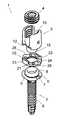
- FIG. 1is a view of this anchor member according to the first embodiment, in exploded perspective view from a first viewing angle;
- FIG. 2is a view similar to FIG. 1 , from another viewing angle;
- FIG. 3is a side view of a ring comprised by this anchor member
- FIG. 4is a perspective view of this ring, enlarged
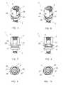
- FIGS. 5, 7 and 9are partial views of the anchor member in the assembled state, in perspective, side and top view, respectively, in a first angular position of said ring;
- FIGS. 6, 8 and 10are views of the anchor member respectively similar to FIGS. 5, 7 and 9 , in a second angular position of said ring;
- FIG. 11is a view of the anchor member according to the second embodiment, in exploded perspective view
- FIG. 12is a longitudinal sectional side view passing through the axis of the anchor member
- FIG. 13is a view of the anchor member similar to FIG. 12 , in a non-final assembled state.
- FIG. 14is a view of the anchor member similar to FIG. 13 , in the final assembly state.
- FIGS. 1 and 2show an anchor member 1 forming part of a vertebral osteosynthesis equipment.
- This equipmentfurther comprises a plurality of anchor members 1 , connecting bars (not shown) designed to connect several vertebrae be treated to one another, these bars being fixed to these vertebrae using anchor members 1 .
- the anchor member 1is of the so-called “tulip” type, i.e., comprising a body 2 , a widened head 3 and a set screw 4 capable to be screwed into the head 3 .
- the body 2comprises a threaded part 5 allowing it to be screwed in the resected pedicle of a vertebra. At its proximal end, it has a collar 6 provided with notches 7 for rotational maneuvering during its screwing, and comprises a spherical articulation cavity 8 defined by a peripheral wall 9 coaxial to the body 2 .
- This peripheral wall 9is crimped on an articulation portion 15 comprised by the head 3 , described later, this crimping assembling the head 3 to the body 2 , with “polyaxiality”, i.e., with articulation of the head 3 relative to the body 2 .
- the wall 9outwardly has a sphere portion shape.
- the head 3is inwardly hollow and has two diametrically opposite openings, such that it forms an engagement duct 10 for a connecting bar. At the base of each opening, the head 3 has a transverse slot 11 , longer than the width of the opening and centered on the median axis of that opening.
- the slot 11is defined, in the radial direction of the head 3 , by a wall forming two recesses 12 at the ends of the slot 11 .
- the head 3also comprises a distal axial portion 15 , spherical or partially spherical, received in the cavity 8 and retained in said cavity by crimping of the wall 9 thereon, as mentioned above.
- the head 3further forms a substantially planar distal bearing face, in which the slots 11 emerge and which includes four cavities 16 with a rounded bottom.
- the anchor member 1also comprises a ring 20 , also visible, and more particularly, in FIGS. 3 and 4 .
- This ring 20has a proximal face from which four bosses 21 protrude in the form of a spherical cap, sized so as to be able, in said first angular position of the ring 20 , to be completely inserted in the cavities 16 , and which are angularly offset from these cavities 16 in said second angular position.
- the ring 20also has a distal face 22 in the form of a recessed surface, capable to bear against the wall 9 with an articulated movement capacity.
- the ring 20also comprises, on its proximal side, two diametrically opposite studs 23 , axially protruding from the proximal side of the ring 20 , longer than they are tall (the length being the dimension of the studs 23 in the direction of the circumference of the head 3 , and the height being their dimension in the direction of the axis of the head 3 ).
- These studs 23are capable to be received in the slots 11 and to be moved in these slots when the ring 20 is maneuvered to pivot along its axis, both in the longitudinal direction of these slots 11 and in the axial direction of the anchor member 1 .
- Each stud 23has, at its longitudinal ends, two bosses 24 protruding toward the inside of the ring 20 , and in its upper face, two indentations 25 capable to receive the connecting bar placed in the duct 10 , in said first and second angular positions of the ring 20 .
- the ring 20further has two diametrically opposite lugs 26 , protruding radially outwardly, which form two radial bearing surfaces 27 for receiving corresponding surfaces of an instrument (not shown) for maneuvering the ring 20 in view of pivoting this ring.
- These radial faces 27are, in said first angular position of the ring 20 , located in a plane substantially perpendicular to the plane passing through the middle of the studs 23 , as shown in FIG. 9 .
- Said instrument for maneuvering the ring 20is tubular so as to be capable to be engaged on the head 3 of an anchor member 1 and forms two radial surfaces engaged with the radial faces 27 . It further includes diametrically opposite notches, perpendicular to these two radial surfaces, that have, in terms of width, a dimension much larger than the diameter of the bar, so as to allow said engagement of the instrument and surfaces 27 while a connecting bar is engaged in the duct 10 of the head 3 and so as to allow the actuation of the ring 20 to pivot between said first angular position and said second angular position.
- the set screw 4is of a known type, being outwardly threaded so as to be capable to be screwed to the inside of the head 3 .
- a series of anchor members 1is placed on a series of vertebrae, with the rings 20 of these anchor members 1 in said first angular position, and without the set screws 4 .
- the connecting baris engaged in the different ducts 10 of these anchor members 1 , this engagement being facilitated by the polyaxiality of the heads 3 .
- the screws 4are next placed on the heads 3 without tightening so as to allow the possibility of sliding of the anchor members 1 along the bar to remain.
- the placement of the barmakes it possible to bring the vertebrae into a correction position, which is, however, slightly lessened by the polyaxiality of the anchor members 1 ; the vertebrae are then brought into a desired complete correction position, then the rings 20 are pivoted in said second angular position, using said maneuvering instrument, eliminating the polyaxiality of the heads 3 .
- a separation or approach of two adjacent anchor members 1can be done if necessary, so as to correct the position of the two vertebrae in which these anchor members 1 are implanted. Once this correction is done, the screws 4 are tightened so as to immobilize the anchor members relative to the bar in the obtained correction position.
- FIGS. 11 to 14show the anchor member 1 according to the second embodiment and make it possible to illustrate a method for manufacturing this anchor member.
- the component elements already described and that are found identically or similarly in the second embodimentare designated using the same references.
- the ring 8has no extensions 23 : the vertebral bar bears directly on this ring at portions thereof located below openings through which the duct 10 emerges outside the head 3 .
- the ring 8is also provided with no lugs 26 and instead comprises two indentations 30 allowing it to pivot relative to the head 3 , using an appropriate instrument (not shown).
- This instrumentcomprises a tubular portion intended to be engaged on the head 3 and two inner lugs intended to be engaged in the indentations 30 ; to allow these inner lugs to cross the head 3 and be capable to be engaged in the indentations 30 , the head 3 comprises two slots 31 capable to slidingly receive these lugs during the engagement of said instrument on the head 3 .
- FIGS. 11 to 14show that the articulation portion comprises two parts 15 a , 15 b , i.e., a lower axial slug 15 a secured to the head 3 and a partially spherical part 15 b .
- the slug 15 ahas a thread and the part 15 b has a tapped hole allowing it to be screwed on this thread, such that the part 15 b can be fixed on this slug 15 a.
- bearing wall 9is made as a part separated from the body 2 .
- this structureis designed to allow the assembly of the anchor member 1 according to the method comprising the following steps:
- the anchor member 1 according to the first embodimentis also made using the same method.
- the inventionthus provides a vertebral osteosynthesis equipment 1 having the decisive advantage of allowing perfect transmission to the vertebrae of the corrections imposed by the curvature of the connecting bar(s) and the separation or approach corrections of two vertebrae, but without making it difficult to engage a bar in the ducts 10 formed by the heads 3 of the anchor members 1 .
Landscapes
- Health & Medical Sciences (AREA)
- Orthopedic Medicine & Surgery (AREA)
- Life Sciences & Earth Sciences (AREA)
- Surgery (AREA)
- Neurology (AREA)
- Heart & Thoracic Surgery (AREA)
- Engineering & Computer Science (AREA)
- Biomedical Technology (AREA)
- Nuclear Medicine, Radiotherapy & Molecular Imaging (AREA)
- Medical Informatics (AREA)
- Molecular Biology (AREA)
- Animal Behavior & Ethology (AREA)
- General Health & Medical Sciences (AREA)
- Public Health (AREA)
- Veterinary Medicine (AREA)
- Surgical Instruments (AREA)
- Prostheses (AREA)
Abstract
Description
Claims (10)
Applications Claiming Priority (3)
| Application Number | Priority Date | Filing Date | Title |
|---|---|---|---|
| FR1553722 | 2015-04-24 | ||
| FR1553722AFR3035318B1 (en) | 2015-04-24 | 2015-04-24 | MATERIAL OF VERTEBRAL OSTEOSYNTHESIS |
| PCT/IB2016/052125WO2016170452A1 (en) | 2015-04-24 | 2016-04-14 | Vertebral osteosynthesis equipment |
Publications (2)
| Publication Number | Publication Date |
|---|---|
| US20180153588A1 US20180153588A1 (en) | 2018-06-07 |
| US10426521B2true US10426521B2 (en) | 2019-10-01 |
Family
ID=53758372
Family Applications (1)
| Application Number | Title | Priority Date | Filing Date |
|---|---|---|---|
| US15/568,605Active2036-07-03US10426521B2 (en) | 2015-04-24 | 2016-04-14 | Vertebral osteosynthesis equipment |
Country Status (7)
| Country | Link |
|---|---|
| US (1) | US10426521B2 (en) |
| EP (1) | EP3285665B1 (en) |
| JP (1) | JP2018517447A (en) |
| AU (1) | AU2016251941B2 (en) |
| ES (1) | ES2699235T3 (en) |
| FR (1) | FR3035318B1 (en) |
| WO (1) | WO2016170452A1 (en) |
Cited By (2)
| Publication number | Priority date | Publication date | Assignee | Title |
|---|---|---|---|---|
| US11083499B2 (en) | 2015-07-24 | 2021-08-10 | Biedermann Technologies Gmbh & Co. Kg | Polyaxial bone anchoring device and instrument for use with the same |
| US11147593B2 (en) | 2019-08-30 | 2021-10-19 | Biedermann Technologies Gmbh & Co. Kg | Bone anchoring device |
Families Citing this family (3)
| Publication number | Priority date | Publication date | Assignee | Title |
|---|---|---|---|---|
| EP4278998B1 (en) | 2016-07-29 | 2025-05-21 | Zimmer Biomet Spine, Inc. | Bone anchor housing limiter |
| EP3501436B1 (en) | 2017-12-22 | 2020-06-03 | Biedermann Technologies GmbH & Co. KG | Polyaxial bone anchoring device and system of an instrument and a polyaxial bone anchoring device |
| EP4129220B1 (en)* | 2021-08-04 | 2024-07-03 | Biedermann Technologies GmbH & Co. KG | Coupling device for coupling a rod to a bone anchoring element and method of manufacturing the same |
Citations (106)
| Publication number | Priority date | Publication date | Assignee | Title |
|---|---|---|---|---|
| US4946458A (en)* | 1986-04-25 | 1990-08-07 | Harms Juergen | Pedicle screw |
| US5628740A (en)* | 1993-12-23 | 1997-05-13 | Mullane; Thomas S. | Articulating toggle bolt bone screw |
| US5725528A (en)* | 1997-02-12 | 1998-03-10 | Third Millennium Engineering, Llc | Modular polyaxial locking pedicle screw |
| US5735851A (en)* | 1996-10-09 | 1998-04-07 | Third Millennium Engineering, Llc | Modular polyaxial locking pedicle screw |
| US5752957A (en)* | 1997-02-12 | 1998-05-19 | Third Millennium Engineering, Llc | Polyaxial mechanism for use with orthopaedic implant devices |
| US5800435A (en)* | 1996-10-09 | 1998-09-01 | Techsys, Llc | Modular spinal plate for use with modular polyaxial locking pedicle screws |
| WO1998055038A1 (en) | 1997-06-03 | 1998-12-10 | Jean Taylor | Multidirectional adaptable vertebral osteosynthesis device with reduced space requirement |
| US6050997A (en)* | 1999-01-25 | 2000-04-18 | Mullane; Thomas S. | Spinal fixation system |
| US20040006342A1 (en)* | 2002-02-13 | 2004-01-08 | Moti Altarac | Posterior polyaxial plate system for the spine |
| US7033358B2 (en)* | 2000-11-07 | 2006-04-25 | Jean Taylor | Vertebral arthrodesis equipment |
| US7163539B2 (en)* | 2004-02-27 | 2007-01-16 | Custom Spine, Inc. | Biased angle polyaxial pedicle screw assembly |
| US7163538B2 (en)* | 2002-02-13 | 2007-01-16 | Cross Medical Products, Inc. | Posterior rod system |
| US20070072493A1 (en)* | 2004-01-27 | 2007-03-29 | Denys Sournac | Vertebral osteosynthesys device |
| US7207992B2 (en)* | 2001-09-28 | 2007-04-24 | Stephen Ritland | Connection rod for screw or hook polyaxial system and method of use |
| US20070093832A1 (en) | 2004-02-27 | 2007-04-26 | Abdelgany Mahmoud F | Spring-loaded, load sharing polyaxial pedicle screw assembly and method |
| US20070100339A1 (en)* | 2003-06-27 | 2007-05-03 | Medicrea Technologies | Vertebral osteosynthesis equipment |
| US20070173817A1 (en)* | 2004-01-27 | 2007-07-26 | Denys Sournac | Vertebral osteosynthesis equipment |
| US20080021464A1 (en)* | 2006-07-19 | 2008-01-24 | Joshua Morin | System and method for a spinal implant locking assembly |
| US20080065073A1 (en)* | 2006-09-08 | 2008-03-13 | Michael Perriello | Offset dynamic motion spinal stabilization system |
| US20090118772A1 (en)* | 2007-06-01 | 2009-05-07 | Jennifer Diederich | Polyaxial bone anchor with increased angulation |
| US7572280B2 (en)* | 2004-10-05 | 2009-08-11 | Warsaw Orthopedic, Inc. | Multi-axial anchor assemblies for spinal implants and methods |
| US20100036437A1 (en)* | 2008-02-26 | 2010-02-11 | Spartek Medical, Inc. | Load-sharing bone anchor having a deflectable post with a compliant ring and method for stabilization of the spine |
| US20100036417A1 (en) | 2008-08-06 | 2010-02-11 | Spine Wave, Inc. | Multi-axial spinal fixation system |
| US20100100137A1 (en) | 2008-10-17 | 2010-04-22 | Warsaw Orthopedics, Inc. | Dynamic Anchor Assembly for Connecting Elements in Spinal Surgical Procedures |
| US7731734B2 (en)* | 2003-06-27 | 2010-06-08 | Medicrea Technologies | Vertebral osteosynthesis equipment |
| US7744635B2 (en)* | 2004-06-09 | 2010-06-29 | Spinal Generations, Llc | Spinal fixation system |
| US20100174322A1 (en)* | 2009-01-03 | 2010-07-08 | Custom Spine, Inc. | Biased Bumper Mechanism and Method |
| US7763054B2 (en)* | 2003-06-27 | 2010-07-27 | Medicrea Technologies | Vertebral osteosynthesis equipment |
| US7819902B2 (en)* | 2004-02-27 | 2010-10-26 | Custom Spine, Inc. | Medialised rod pedicle screw assembly |
| US7850719B2 (en)* | 2004-05-26 | 2010-12-14 | Warsaw Orthopedic, Inc. | Spinal implant apparatus |
| US7862594B2 (en)* | 2004-02-27 | 2011-01-04 | Custom Spine, Inc. | Polyaxial pedicle screw assembly |
| US7875060B2 (en)* | 2003-09-24 | 2011-01-25 | Spinefrontier, LLS | Multi-axial screw with a spherical landing |
| US20110046684A1 (en)* | 2004-02-27 | 2011-02-24 | Custom Spine, Inc. | Screw Assembly and Method |
| US7927359B2 (en)* | 2005-10-06 | 2011-04-19 | Paradigm Spine, Llc | Polyaxial screw |
| US8002807B2 (en)* | 2009-01-03 | 2011-08-23 | Custom Spine, Inc. | Sealed lubrication system and method for dynamic stabilization system |
| US20110208248A1 (en) | 2007-10-23 | 2011-08-25 | Michael Barrus | Polyaxial screw assembly |
| US8016861B2 (en)* | 2008-02-26 | 2011-09-13 | Spartek Medical, Inc. | Versatile polyaxial connector assembly and method for dynamic stabilization of the spine |
| US8048132B2 (en)* | 2009-07-03 | 2011-11-01 | Accumis Inc. | Spine fixation device |
| US8057515B2 (en)* | 2008-02-26 | 2011-11-15 | Spartek Medical, Inc. | Load-sharing anchor having a deflectable post and centering spring and method for dynamic stabilization of the spine |
| US8066746B2 (en)* | 2008-12-23 | 2011-11-29 | Globus Medical, Inc. | Variable angle connection assembly |
| US8083775B2 (en)* | 2008-02-26 | 2011-12-27 | Spartek Medical, Inc. | Load-sharing bone anchor having a natural center of rotation and method for dynamic stabilization of the spine |
| US8092503B2 (en)* | 2008-05-15 | 2012-01-10 | Innovasis, Inc. | Polyaxial screw system |
| US20120010658A1 (en)* | 2010-07-08 | 2012-01-12 | X-Spine Systems, Inc. | Spinal stabilization system utilizing screw and external facet and/or lamina fixation |
| US8097020B2 (en)* | 2004-02-27 | 2012-01-17 | Custom Spine, Inc. | Pedicle dynamic facet arthroplasty system and method |
| US8097024B2 (en)* | 2008-02-26 | 2012-01-17 | Spartek Medical, Inc. | Load-sharing bone anchor having a deflectable post and method for stabilization of the spine |
| US8097023B2 (en)* | 2003-11-24 | 2012-01-17 | Warsaw Orthopedic, Inc. | Grommet assembly |
| US20120035667A1 (en)* | 2010-08-06 | 2012-02-09 | Warsaw Orthopedic, Inc. | Locking mechanisms for pivoting bone anchors |
| US8137384B2 (en)* | 2008-09-02 | 2012-03-20 | Bhdl Holdings, Llc | Modular pedicle screw system |
| US20120083845A1 (en)* | 2010-10-05 | 2012-04-05 | Spartek Medical, Inc. | Compound spinal rod and method for dynamic stabilization of the spine |
| US20120095512A1 (en)* | 2010-10-18 | 2012-04-19 | Raj Nihalani | Cross connectors |
| US8162990B2 (en)* | 2006-11-16 | 2012-04-24 | Spine Wave, Inc. | Multi-axial spinal fixation system |
| US8192470B2 (en)* | 2007-07-31 | 2012-06-05 | Biedermann Technologies Gmbh & Co. Kg | Bone anchoring device |
| US20120143257A1 (en)* | 2010-12-02 | 2012-06-07 | Spartek Medical, Inc. | Low profile spinal prosthesis incorporating a cannulated bone anchor having a deflectable post and a compound spinal rod |
| US20120158065A1 (en)* | 2009-06-22 | 2012-06-21 | Jean-Luc Jouve | Vertebral osteosynthesis equipment |
| US8211155B2 (en)* | 2008-02-26 | 2012-07-03 | Spartek Medical, Inc. | Load-sharing bone anchor having a durable compliant member and method for dynamic stabilization of the spine |
| US20120197309A1 (en)* | 2011-01-28 | 2012-08-02 | Warsaw Orthopedic, Inc. | Bone Anchor Including an Elongate Post With Break-Off Features |
| US20120221055A1 (en)* | 2009-03-26 | 2012-08-30 | Spontech Spine Intelligence Group Ag | Spine Fixation System |
| US20120221053A1 (en)* | 2009-07-30 | 2012-08-30 | Spontech Spine Intelligence Group Ag | Spine Fixation System |
| US8257401B2 (en)* | 2008-02-12 | 2012-09-04 | Spinal U.S.A. | Bottom mounted pedical screw assembly |
| US8308772B2 (en)* | 2003-06-27 | 2012-11-13 | Medicrea Technologies | Vertebral osteosynthesis equipment |
| US20120290010A1 (en)* | 2009-11-18 | 2012-11-15 | Seaspine, Inc. | Flexible Screw Head Constructs for Spinal Stabilization |
| US8333792B2 (en)* | 2008-02-26 | 2012-12-18 | Spartek Medical, Inc. | Load-sharing bone anchor having a deflectable post and method for dynamic stabilization of the spine |
| US8337536B2 (en)* | 2008-02-26 | 2012-12-25 | Spartek Medical, Inc. | Load-sharing bone anchor having a deflectable post with a compliant ring and method for stabilization of the spine |
| US8398683B2 (en)* | 2007-10-23 | 2013-03-19 | Pioneer Surgical Technology, Inc. | Rod coupling assembly and methods for bone fixation |
| US8409256B2 (en)* | 2006-12-28 | 2013-04-02 | Depuy Spine, Inc. | Spinal anchoring screw |
| US8430913B2 (en)* | 2009-06-10 | 2013-04-30 | Spine Wave, Inc. | Devices and methods for adding an additional level of fixation to an existing construct |
| US8480713B2 (en)* | 2010-07-28 | 2013-07-09 | Warsaw Orthopedic, Inc. | Adjustable spinal connector assembly |
| US8506609B2 (en)* | 2008-12-30 | 2013-08-13 | Biedermann Technologies Gmbh & Co. Kg | Receiving part for receiving a rod for coupling the rod to a bone anchoring element and a bone anchoring device with such a receiving part |
| US20130253595A1 (en)* | 2012-03-26 | 2013-09-26 | Spartek Medical, Inc. | System and method for securing an implant to a bone containing bone cement |
| US8585741B2 (en)* | 2007-07-19 | 2013-11-19 | DePuy Synthes Products, LLC | Clamps used for interconnecting a bone anchor to a rod |
| US8617216B2 (en)* | 2010-04-05 | 2013-12-31 | David L. Brumfield | Fully-adjustable bone fixation device |
| US8636781B2 (en)* | 2008-11-28 | 2014-01-28 | Biedermann Technologies Gmbh & Co. Kg | Receiving part for receiving a rod for coupling the rod to a bone anchoring element and a bone anchoring device with such a receiving part |
| US20140074169A1 (en)* | 2012-09-13 | 2014-03-13 | Warsaw Orthopedic, Inc. | Spinal correction system and method |
| US20140088650A1 (en)* | 2012-08-16 | 2014-03-27 | Spontech Spine Intelligence Group Ag | Polyaxial Connector for Spinal Fixation Systems |
| US8777954B2 (en)* | 2010-06-18 | 2014-07-15 | Spine Wave, Inc. | Pedicle screw extension for use in percutaneous spinal fixation |
| US8940032B2 (en)* | 2011-10-26 | 2015-01-27 | Globus Medical, Inc. | Connection assembly |
| US9017390B2 (en)* | 2011-11-14 | 2015-04-28 | Biedermann Technologies Gmbh & Co. Kg | Polyaxial bone anchoring device |
| US20150134006A1 (en)* | 2013-11-08 | 2015-05-14 | Blackstone Medical, Inc. | Lockable Pedicle Fastener |
| US9101405B2 (en)* | 2012-02-10 | 2015-08-11 | Warsaw Orthopedic, Inc. | Vertebral implant and connector |
| US9113960B2 (en)* | 2010-06-08 | 2015-08-25 | Globus Medical, Inc. | Conforming bone stabilization receiver |
| US9131971B2 (en)* | 2011-11-14 | 2015-09-15 | Biedermann Technologies Gmbh & Co. Kg | Polyaxial bone anchoring device |
| US9144441B2 (en)* | 2011-09-30 | 2015-09-29 | Biedermann Technologies Gmbh & Co. Kg | Bone anchoring device and tool cooperating with such a bone anchoring device |
| US9186184B2 (en)* | 2011-02-14 | 2015-11-17 | Pioneer Surgical Technology, Inc. | Spinal fixation system and method |
| US9192412B2 (en)* | 2011-07-25 | 2015-11-24 | Medicrea International | Anchor member for vertebral osteosynthesis equipment |
| US9198693B2 (en)* | 2011-12-14 | 2015-12-01 | Innovative Surgical Designs, Inc. | Minimally invasive method and apparatus for stabilizing the spinal column |
| US9247974B2 (en)* | 2012-07-06 | 2016-02-02 | Clariance | Polyaxial screw with mechanical thread and its friction device |
| US20160058476A1 (en)* | 2013-04-19 | 2016-03-03 | Medicrea International | Revision assembly for an item of vertebral osteosynthesis equipment |
| US9333016B2 (en)* | 2012-07-03 | 2016-05-10 | Biedermann Technologies Gmbh & Co. Kg | Polyaxial bone anchoring device |
| US9452006B2 (en)* | 2011-09-15 | 2016-09-27 | Biedermann Technologies Gmbh & Co. Kg | Polyaxial bone anchoring device with enlarged pivot angle |
| US9456859B2 (en)* | 2011-10-05 | 2016-10-04 | Aesculap Ag | Readjustable polyaxial pedicle screw |
| US20160287293A1 (en)* | 2013-11-22 | 2016-10-06 | Spinal Balance, Inc. | Poly-Axial Pedicle Screw Assembly and Packaging Therefor |
| US20170020574A1 (en)* | 2015-07-24 | 2017-01-26 | Timo Biedermann | Polyaxial bone anchoring device and instrument for use with the same |
| US9579125B2 (en)* | 2013-02-09 | 2017-02-28 | Vertiscrew, Llc | Bone screw |
| US9649137B2 (en)* | 2013-09-09 | 2017-05-16 | James A. Rinner | Spinal stabilization system |
| US9801664B2 (en)* | 2013-03-15 | 2017-10-31 | Blackstone Medical, Inc. | Hook with rotating saddle and rotatable mono axial pedicle screw |
| US9855078B2 (en)* | 2015-10-05 | 2018-01-02 | Globus Medical, Inc. | Spinal anchoring system |
| US9861388B2 (en)* | 2014-11-20 | 2018-01-09 | Biedermann Technologies Gmbh & Co. Kg | Receiving part for coupling a bone anchor to a rod and bone anchoring device with such a receiving part |
| US20180036039A1 (en)* | 2016-08-04 | 2018-02-08 | Biedermann Technologies Gmbh & Co. Kg | Polyaxial bone anchoring device and system including an instrument and a polyaxial bone anchoring device |
| US20180055545A1 (en)* | 2016-08-24 | 2018-03-01 | Biedermann Technologies Gmbh & Co. Kg | Instrument for locking and unlocking a head of a bone anchor in a polyaxial bone anchoring device |
| US20180055542A1 (en)* | 2016-08-24 | 2018-03-01 | Biedermann Technologies Gmbh & Co. Kg | Polyaxial bone anchoring device and system of an instrument and a polyaxial bone anchoring device |
| US20180092670A1 (en)* | 2016-10-05 | 2018-04-05 | Spinefrontier, Inc | System and method for spinal fixation via a trans-facet pedicle screw assembly |
| US9987047B2 (en)* | 2013-10-07 | 2018-06-05 | Spine Wave, Inc. | Translating polyaxial screw |
| US20180206896A1 (en)* | 2017-01-23 | 2018-07-26 | Mantiz Logtech Co., Ltd. | Pedicle screw with quadruple screw thread |
| US10098669B2 (en)* | 2015-10-14 | 2018-10-16 | Alphatec Spine, Inc. | Polyaxial bone screw and bushing |
| US10117679B2 (en)* | 2015-03-02 | 2018-11-06 | Globus Medical, Inc. | Adjustable height pedicle screw |
| US20190038319A1 (en)* | 2017-08-03 | 2019-02-07 | Timo Biedermann | Stabilization device for bones or vertebrae |
- 2015
- 2015-04-24FRFR1553722Apatent/FR3035318B1/ennot_activeExpired - Fee Related
- 2016
- 2016-04-14WOPCT/IB2016/052125patent/WO2016170452A1/ennot_activeCeased
- 2016-04-14ESES16718018Tpatent/ES2699235T3/enactiveActive
- 2016-04-14EPEP16718018.1Apatent/EP3285665B1/ennot_activeNot-in-force
- 2016-04-14AUAU2016251941Apatent/AU2016251941B2/ennot_activeExpired - Fee Related
- 2016-04-14JPJP2017553176Apatent/JP2018517447A/ennot_activeCeased
- 2016-04-14USUS15/568,605patent/US10426521B2/enactiveActive
Patent Citations (109)
| Publication number | Priority date | Publication date | Assignee | Title |
|---|---|---|---|---|
| US4946458A (en)* | 1986-04-25 | 1990-08-07 | Harms Juergen | Pedicle screw |
| US5628740A (en)* | 1993-12-23 | 1997-05-13 | Mullane; Thomas S. | Articulating toggle bolt bone screw |
| US5735851A (en)* | 1996-10-09 | 1998-04-07 | Third Millennium Engineering, Llc | Modular polyaxial locking pedicle screw |
| US5800435A (en)* | 1996-10-09 | 1998-09-01 | Techsys, Llc | Modular spinal plate for use with modular polyaxial locking pedicle screws |
| US5725528A (en)* | 1997-02-12 | 1998-03-10 | Third Millennium Engineering, Llc | Modular polyaxial locking pedicle screw |
| US5752957A (en)* | 1997-02-12 | 1998-05-19 | Third Millennium Engineering, Llc | Polyaxial mechanism for use with orthopaedic implant devices |
| WO1998055038A1 (en) | 1997-06-03 | 1998-12-10 | Jean Taylor | Multidirectional adaptable vertebral osteosynthesis device with reduced space requirement |
| US6050997A (en)* | 1999-01-25 | 2000-04-18 | Mullane; Thomas S. | Spinal fixation system |
| US7033358B2 (en)* | 2000-11-07 | 2006-04-25 | Jean Taylor | Vertebral arthrodesis equipment |
| US7207992B2 (en)* | 2001-09-28 | 2007-04-24 | Stephen Ritland | Connection rod for screw or hook polyaxial system and method of use |
| US20040006342A1 (en)* | 2002-02-13 | 2004-01-08 | Moti Altarac | Posterior polyaxial plate system for the spine |
| US7163538B2 (en)* | 2002-02-13 | 2007-01-16 | Cross Medical Products, Inc. | Posterior rod system |
| US8308772B2 (en)* | 2003-06-27 | 2012-11-13 | Medicrea Technologies | Vertebral osteosynthesis equipment |
| US7731734B2 (en)* | 2003-06-27 | 2010-06-08 | Medicrea Technologies | Vertebral osteosynthesis equipment |
| US20070100339A1 (en)* | 2003-06-27 | 2007-05-03 | Medicrea Technologies | Vertebral osteosynthesis equipment |
| US7763054B2 (en)* | 2003-06-27 | 2010-07-27 | Medicrea Technologies | Vertebral osteosynthesis equipment |
| US7875060B2 (en)* | 2003-09-24 | 2011-01-25 | Spinefrontier, LLS | Multi-axial screw with a spherical landing |
| US8097023B2 (en)* | 2003-11-24 | 2012-01-17 | Warsaw Orthopedic, Inc. | Grommet assembly |
| US20070072493A1 (en)* | 2004-01-27 | 2007-03-29 | Denys Sournac | Vertebral osteosynthesys device |
| US20070173817A1 (en)* | 2004-01-27 | 2007-07-26 | Denys Sournac | Vertebral osteosynthesis equipment |
| US7862594B2 (en)* | 2004-02-27 | 2011-01-04 | Custom Spine, Inc. | Polyaxial pedicle screw assembly |
| US20110046684A1 (en)* | 2004-02-27 | 2011-02-24 | Custom Spine, Inc. | Screw Assembly and Method |
| US7163539B2 (en)* | 2004-02-27 | 2007-01-16 | Custom Spine, Inc. | Biased angle polyaxial pedicle screw assembly |
| US20070093832A1 (en) | 2004-02-27 | 2007-04-26 | Abdelgany Mahmoud F | Spring-loaded, load sharing polyaxial pedicle screw assembly and method |
| US8097020B2 (en)* | 2004-02-27 | 2012-01-17 | Custom Spine, Inc. | Pedicle dynamic facet arthroplasty system and method |
| US7819902B2 (en)* | 2004-02-27 | 2010-10-26 | Custom Spine, Inc. | Medialised rod pedicle screw assembly |
| US7892257B2 (en)* | 2004-02-27 | 2011-02-22 | Custom Spine, Inc. | Spring loaded, load sharing polyaxial pedicle screw assembly and method |
| US7850719B2 (en)* | 2004-05-26 | 2010-12-14 | Warsaw Orthopedic, Inc. | Spinal implant apparatus |
| US7744635B2 (en)* | 2004-06-09 | 2010-06-29 | Spinal Generations, Llc | Spinal fixation system |
| US7572280B2 (en)* | 2004-10-05 | 2009-08-11 | Warsaw Orthopedic, Inc. | Multi-axial anchor assemblies for spinal implants and methods |
| US7927359B2 (en)* | 2005-10-06 | 2011-04-19 | Paradigm Spine, Llc | Polyaxial screw |
| US20080021464A1 (en)* | 2006-07-19 | 2008-01-24 | Joshua Morin | System and method for a spinal implant locking assembly |
| US20080065073A1 (en)* | 2006-09-08 | 2008-03-13 | Michael Perriello | Offset dynamic motion spinal stabilization system |
| US8162990B2 (en)* | 2006-11-16 | 2012-04-24 | Spine Wave, Inc. | Multi-axial spinal fixation system |
| US8409256B2 (en)* | 2006-12-28 | 2013-04-02 | Depuy Spine, Inc. | Spinal anchoring screw |
| US20090118772A1 (en)* | 2007-06-01 | 2009-05-07 | Jennifer Diederich | Polyaxial bone anchor with increased angulation |
| US8585741B2 (en)* | 2007-07-19 | 2013-11-19 | DePuy Synthes Products, LLC | Clamps used for interconnecting a bone anchor to a rod |
| US8192470B2 (en)* | 2007-07-31 | 2012-06-05 | Biedermann Technologies Gmbh & Co. Kg | Bone anchoring device |
| US20110208248A1 (en) | 2007-10-23 | 2011-08-25 | Michael Barrus | Polyaxial screw assembly |
| US8398683B2 (en)* | 2007-10-23 | 2013-03-19 | Pioneer Surgical Technology, Inc. | Rod coupling assembly and methods for bone fixation |
| US8257401B2 (en)* | 2008-02-12 | 2012-09-04 | Spinal U.S.A. | Bottom mounted pedical screw assembly |
| US8211155B2 (en)* | 2008-02-26 | 2012-07-03 | Spartek Medical, Inc. | Load-sharing bone anchor having a durable compliant member and method for dynamic stabilization of the spine |
| US20100036437A1 (en)* | 2008-02-26 | 2010-02-11 | Spartek Medical, Inc. | Load-sharing bone anchor having a deflectable post with a compliant ring and method for stabilization of the spine |
| US8083775B2 (en)* | 2008-02-26 | 2011-12-27 | Spartek Medical, Inc. | Load-sharing bone anchor having a natural center of rotation and method for dynamic stabilization of the spine |
| US8016861B2 (en)* | 2008-02-26 | 2011-09-13 | Spartek Medical, Inc. | Versatile polyaxial connector assembly and method for dynamic stabilization of the spine |
| US8097024B2 (en)* | 2008-02-26 | 2012-01-17 | Spartek Medical, Inc. | Load-sharing bone anchor having a deflectable post and method for stabilization of the spine |
| US8333792B2 (en)* | 2008-02-26 | 2012-12-18 | Spartek Medical, Inc. | Load-sharing bone anchor having a deflectable post and method for dynamic stabilization of the spine |
| US8057515B2 (en)* | 2008-02-26 | 2011-11-15 | Spartek Medical, Inc. | Load-sharing anchor having a deflectable post and centering spring and method for dynamic stabilization of the spine |
| US8337536B2 (en)* | 2008-02-26 | 2012-12-25 | Spartek Medical, Inc. | Load-sharing bone anchor having a deflectable post with a compliant ring and method for stabilization of the spine |
| US8092503B2 (en)* | 2008-05-15 | 2012-01-10 | Innovasis, Inc. | Polyaxial screw system |
| US8491639B2 (en)* | 2008-08-06 | 2013-07-23 | Spine Wave, Inc. | Multi-axial spinal fixation system |
| US20100036417A1 (en) | 2008-08-06 | 2010-02-11 | Spine Wave, Inc. | Multi-axial spinal fixation system |
| US8137384B2 (en)* | 2008-09-02 | 2012-03-20 | Bhdl Holdings, Llc | Modular pedicle screw system |
| US8292934B2 (en)* | 2008-10-17 | 2012-10-23 | Warsaw Orthopedic, Inc. | Dynamic anchor assembly for connecting elements in spinal surgical procedures |
| US20100100137A1 (en) | 2008-10-17 | 2010-04-22 | Warsaw Orthopedics, Inc. | Dynamic Anchor Assembly for Connecting Elements in Spinal Surgical Procedures |
| US8636781B2 (en)* | 2008-11-28 | 2014-01-28 | Biedermann Technologies Gmbh & Co. Kg | Receiving part for receiving a rod for coupling the rod to a bone anchoring element and a bone anchoring device with such a receiving part |
| US8066746B2 (en)* | 2008-12-23 | 2011-11-29 | Globus Medical, Inc. | Variable angle connection assembly |
| US8506609B2 (en)* | 2008-12-30 | 2013-08-13 | Biedermann Technologies Gmbh & Co. Kg | Receiving part for receiving a rod for coupling the rod to a bone anchoring element and a bone anchoring device with such a receiving part |
| US8002807B2 (en)* | 2009-01-03 | 2011-08-23 | Custom Spine, Inc. | Sealed lubrication system and method for dynamic stabilization system |
| US20100174322A1 (en)* | 2009-01-03 | 2010-07-08 | Custom Spine, Inc. | Biased Bumper Mechanism and Method |
| US20120221055A1 (en)* | 2009-03-26 | 2012-08-30 | Spontech Spine Intelligence Group Ag | Spine Fixation System |
| US8430913B2 (en)* | 2009-06-10 | 2013-04-30 | Spine Wave, Inc. | Devices and methods for adding an additional level of fixation to an existing construct |
| US20120158065A1 (en)* | 2009-06-22 | 2012-06-21 | Jean-Luc Jouve | Vertebral osteosynthesis equipment |
| US8048132B2 (en)* | 2009-07-03 | 2011-11-01 | Accumis Inc. | Spine fixation device |
| US20120221053A1 (en)* | 2009-07-30 | 2012-08-30 | Spontech Spine Intelligence Group Ag | Spine Fixation System |
| US20120290010A1 (en)* | 2009-11-18 | 2012-11-15 | Seaspine, Inc. | Flexible Screw Head Constructs for Spinal Stabilization |
| US8617216B2 (en)* | 2010-04-05 | 2013-12-31 | David L. Brumfield | Fully-adjustable bone fixation device |
| US9113960B2 (en)* | 2010-06-08 | 2015-08-25 | Globus Medical, Inc. | Conforming bone stabilization receiver |
| US8777954B2 (en)* | 2010-06-18 | 2014-07-15 | Spine Wave, Inc. | Pedicle screw extension for use in percutaneous spinal fixation |
| US20120010658A1 (en)* | 2010-07-08 | 2012-01-12 | X-Spine Systems, Inc. | Spinal stabilization system utilizing screw and external facet and/or lamina fixation |
| US8480713B2 (en)* | 2010-07-28 | 2013-07-09 | Warsaw Orthopedic, Inc. | Adjustable spinal connector assembly |
| US20120035667A1 (en)* | 2010-08-06 | 2012-02-09 | Warsaw Orthopedic, Inc. | Locking mechanisms for pivoting bone anchors |
| US20120083845A1 (en)* | 2010-10-05 | 2012-04-05 | Spartek Medical, Inc. | Compound spinal rod and method for dynamic stabilization of the spine |
| US20120095512A1 (en)* | 2010-10-18 | 2012-04-19 | Raj Nihalani | Cross connectors |
| US20120143257A1 (en)* | 2010-12-02 | 2012-06-07 | Spartek Medical, Inc. | Low profile spinal prosthesis incorporating a cannulated bone anchor having a deflectable post and a compound spinal rod |
| US20120197309A1 (en)* | 2011-01-28 | 2012-08-02 | Warsaw Orthopedic, Inc. | Bone Anchor Including an Elongate Post With Break-Off Features |
| US9186184B2 (en)* | 2011-02-14 | 2015-11-17 | Pioneer Surgical Technology, Inc. | Spinal fixation system and method |
| US9192412B2 (en)* | 2011-07-25 | 2015-11-24 | Medicrea International | Anchor member for vertebral osteosynthesis equipment |
| US9452006B2 (en)* | 2011-09-15 | 2016-09-27 | Biedermann Technologies Gmbh & Co. Kg | Polyaxial bone anchoring device with enlarged pivot angle |
| US9144441B2 (en)* | 2011-09-30 | 2015-09-29 | Biedermann Technologies Gmbh & Co. Kg | Bone anchoring device and tool cooperating with such a bone anchoring device |
| US9456859B2 (en)* | 2011-10-05 | 2016-10-04 | Aesculap Ag | Readjustable polyaxial pedicle screw |
| US8940032B2 (en)* | 2011-10-26 | 2015-01-27 | Globus Medical, Inc. | Connection assembly |
| US9017390B2 (en)* | 2011-11-14 | 2015-04-28 | Biedermann Technologies Gmbh & Co. Kg | Polyaxial bone anchoring device |
| US9131971B2 (en)* | 2011-11-14 | 2015-09-15 | Biedermann Technologies Gmbh & Co. Kg | Polyaxial bone anchoring device |
| US9198693B2 (en)* | 2011-12-14 | 2015-12-01 | Innovative Surgical Designs, Inc. | Minimally invasive method and apparatus for stabilizing the spinal column |
| US9101405B2 (en)* | 2012-02-10 | 2015-08-11 | Warsaw Orthopedic, Inc. | Vertebral implant and connector |
| US20130253595A1 (en)* | 2012-03-26 | 2013-09-26 | Spartek Medical, Inc. | System and method for securing an implant to a bone containing bone cement |
| US9333016B2 (en)* | 2012-07-03 | 2016-05-10 | Biedermann Technologies Gmbh & Co. Kg | Polyaxial bone anchoring device |
| US9247974B2 (en)* | 2012-07-06 | 2016-02-02 | Clariance | Polyaxial screw with mechanical thread and its friction device |
| US20140088650A1 (en)* | 2012-08-16 | 2014-03-27 | Spontech Spine Intelligence Group Ag | Polyaxial Connector for Spinal Fixation Systems |
| US20140074169A1 (en)* | 2012-09-13 | 2014-03-13 | Warsaw Orthopedic, Inc. | Spinal correction system and method |
| US9579125B2 (en)* | 2013-02-09 | 2017-02-28 | Vertiscrew, Llc | Bone screw |
| US9801664B2 (en)* | 2013-03-15 | 2017-10-31 | Blackstone Medical, Inc. | Hook with rotating saddle and rotatable mono axial pedicle screw |
| US20160058476A1 (en)* | 2013-04-19 | 2016-03-03 | Medicrea International | Revision assembly for an item of vertebral osteosynthesis equipment |
| US9649137B2 (en)* | 2013-09-09 | 2017-05-16 | James A. Rinner | Spinal stabilization system |
| US9987047B2 (en)* | 2013-10-07 | 2018-06-05 | Spine Wave, Inc. | Translating polyaxial screw |
| US20150134006A1 (en)* | 2013-11-08 | 2015-05-14 | Blackstone Medical, Inc. | Lockable Pedicle Fastener |
| US20160287293A1 (en)* | 2013-11-22 | 2016-10-06 | Spinal Balance, Inc. | Poly-Axial Pedicle Screw Assembly and Packaging Therefor |
| US9861388B2 (en)* | 2014-11-20 | 2018-01-09 | Biedermann Technologies Gmbh & Co. Kg | Receiving part for coupling a bone anchor to a rod and bone anchoring device with such a receiving part |
| US10117679B2 (en)* | 2015-03-02 | 2018-11-06 | Globus Medical, Inc. | Adjustable height pedicle screw |
| US20170020574A1 (en)* | 2015-07-24 | 2017-01-26 | Timo Biedermann | Polyaxial bone anchoring device and instrument for use with the same |
| US9855078B2 (en)* | 2015-10-05 | 2018-01-02 | Globus Medical, Inc. | Spinal anchoring system |
| US10098669B2 (en)* | 2015-10-14 | 2018-10-16 | Alphatec Spine, Inc. | Polyaxial bone screw and bushing |
| US20180036039A1 (en)* | 2016-08-04 | 2018-02-08 | Biedermann Technologies Gmbh & Co. Kg | Polyaxial bone anchoring device and system including an instrument and a polyaxial bone anchoring device |
| US20180055545A1 (en)* | 2016-08-24 | 2018-03-01 | Biedermann Technologies Gmbh & Co. Kg | Instrument for locking and unlocking a head of a bone anchor in a polyaxial bone anchoring device |
| US20180055542A1 (en)* | 2016-08-24 | 2018-03-01 | Biedermann Technologies Gmbh & Co. Kg | Polyaxial bone anchoring device and system of an instrument and a polyaxial bone anchoring device |
| US20180092670A1 (en)* | 2016-10-05 | 2018-04-05 | Spinefrontier, Inc | System and method for spinal fixation via a trans-facet pedicle screw assembly |
| US20180206896A1 (en)* | 2017-01-23 | 2018-07-26 | Mantiz Logtech Co., Ltd. | Pedicle screw with quadruple screw thread |
| US20190038319A1 (en)* | 2017-08-03 | 2019-02-07 | Timo Biedermann | Stabilization device for bones or vertebrae |
Cited By (5)
| Publication number | Priority date | Publication date | Assignee | Title |
|---|---|---|---|---|
| US11083499B2 (en) | 2015-07-24 | 2021-08-10 | Biedermann Technologies Gmbh & Co. Kg | Polyaxial bone anchoring device and instrument for use with the same |
| US11399874B2 (en) | 2015-07-24 | 2022-08-02 | Biedermann Technologies Gmbh & Co. Kg | Polyaxial bone anchoring device and instrument for use with the same |
| US12029452B2 (en) | 2015-07-24 | 2024-07-09 | Biedermann Technologies Gmbh & Co. Kg | Polyaxial bone anchoring device and instrument for use with the same |
| US11147593B2 (en) | 2019-08-30 | 2021-10-19 | Biedermann Technologies Gmbh & Co. Kg | Bone anchoring device |
| US12089878B2 (en) | 2019-08-30 | 2024-09-17 | Biedermann Technologies Gmbh & Co. Kg | Bone anchoring device |
Also Published As
| Publication number | Publication date |
|---|---|
| AU2016251941A1 (en) | 2017-10-26 |
| FR3035318A1 (en) | 2016-10-28 |
| FR3035318B1 (en) | 2017-05-19 |
| AU2016251941B2 (en) | 2019-12-19 |
| JP2018517447A (en) | 2018-07-05 |
| WO2016170452A1 (en) | 2016-10-27 |
| ES2699235T3 (en) | 2019-02-08 |
| EP3285665B1 (en) | 2018-10-31 |
| US20180153588A1 (en) | 2018-06-07 |
| EP3285665A1 (en) | 2018-02-28 |
Similar Documents
| Publication | Publication Date | Title |
|---|---|---|
| US10426521B2 (en) | Vertebral osteosynthesis equipment | |
| US12082851B2 (en) | Polyaxial pedicle screw | |
| US10561454B2 (en) | Articulating implant connectors and related methods | |
| US9924974B2 (en) | Polyaxial bone anchoring device | |
| US7445627B2 (en) | Polyaxial pedicle screw assembly | |
| US8771319B2 (en) | Rod to rod cross connector | |
| US8702761B1 (en) | Bone screw assembly for limited angulation | |
| KR101360009B1 (en) | transconnector | |
| US8002806B2 (en) | Bottom loading multi-axial screw assembly | |
| EP2502594B1 (en) | Polyaxial pedicle screw and fixation system kit comprising said screw | |
| CN100444809C (en) | Linking transconnector for coupling spinal rods | |
| US8066744B2 (en) | Keyed crown orientation for multi-axial screws | |
| US9956016B2 (en) | Modular bone plate and member of such a modular bone plate | |
| US8097025B2 (en) | Pedicle screw system configured to receive a straight or curved rod | |
| US9724145B2 (en) | Bone anchor assemblies with multiple component bottom loading bone anchors | |
| KR20080087824A (en) | Variable Angle Offset Spinal Connector Assembly | |
| KR101622966B1 (en) | Multiaxial connecting rod assembly of spinal fixation device | |
| WO2017035186A1 (en) | Convertible bone screw assembly | |
| US10624677B2 (en) | Vertebral osteosynthesis equipment | |
| US10610264B2 (en) | Polyaxial vertebral anchoring device for straightening a vertebra |
Legal Events
| Date | Code | Title | Description |
|---|---|---|---|
| AS | Assignment | Owner name:MEDICREA INTERNATIONAL, FRANCE Free format text:ASSIGNMENT OF ASSIGNORS INTEREST;ASSIGNORS:MOSNIER, THOMAS;SCHWAB, FRANK;SIGNING DATES FROM 20171017 TO 20171023;REEL/FRAME:043924/0386 | |
| FEPP | Fee payment procedure | Free format text:ENTITY STATUS SET TO UNDISCOUNTED (ORIGINAL EVENT CODE: BIG.); ENTITY STATUS OF PATENT OWNER: LARGE ENTITY Free format text:ENTITY STATUS SET TO UNDISCOUNTED (ORIGINAL EVENT CODE: BIG.); ENTITY STATUS OF PATENT OWNER: SMALL ENTITY | |
| FEPP | Fee payment procedure | Free format text:ENTITY STATUS SET TO SMALL (ORIGINAL EVENT CODE: SMAL); ENTITY STATUS OF PATENT OWNER: LARGE ENTITY Free format text:ENTITY STATUS SET TO SMALL (ORIGINAL EVENT CODE: SMAL); ENTITY STATUS OF PATENT OWNER: SMALL ENTITY | |
| STPP | Information on status: patent application and granting procedure in general | Free format text:DOCKETED NEW CASE - READY FOR EXAMINATION | |
| AS | Assignment | Owner name:PERCEPTIVE CREDIT HOLDINGS II, LP, NEW YORK Free format text:PATENT SECURITY AGREEMENT;ASSIGNOR:MEDICREA INTERNATIONAL;REEL/FRAME:048174/0183 Effective date:20181127 | |
| STPP | Information on status: patent application and granting procedure in general | Free format text:NOTICE OF ALLOWANCE MAILED -- APPLICATION RECEIVED IN OFFICE OF PUBLICATIONS | |
| STPP | Information on status: patent application and granting procedure in general | Free format text:AWAITING TC RESP., ISSUE FEE NOT PAID | |
| STPP | Information on status: patent application and granting procedure in general | Free format text:AWAITING TC RESP, ISSUE FEE PAYMENT RECEIVED | |
| STPP | Information on status: patent application and granting procedure in general | Free format text:AWAITING TC RESP, ISSUE FEE PAYMENT VERIFIED | |
| STPP | Information on status: patent application and granting procedure in general | Free format text:PUBLICATIONS -- ISSUE FEE PAYMENT VERIFIED | |
| STCF | Information on status: patent grant | Free format text:PATENTED CASE | |
| AS | Assignment | Owner name:MEDICREA INTERNATIONAL, FRANCE Free format text:RELEASE BY SECURED PARTY;ASSIGNOR:PERCEPTIVE CREDIT HOLDINGS II, LP;REEL/FRAME:054485/0305 Effective date:20201113 | |
| FEPP | Fee payment procedure | Free format text:ENTITY STATUS SET TO UNDISCOUNTED (ORIGINAL EVENT CODE: BIG.); ENTITY STATUS OF PATENT OWNER: LARGE ENTITY | |
| MAFP | Maintenance fee payment | Free format text:PAYMENT OF MAINTENANCE FEE, 4TH YEAR, LARGE ENTITY (ORIGINAL EVENT CODE: M1551); ENTITY STATUS OF PATENT OWNER: LARGE ENTITY Year of fee payment:4 |