US10426086B2 - Chaff spreader with seed bruising - Google Patents
Chaff spreader with seed bruisingDownload PDFInfo
- Publication number
- US10426086B2 US10426086B2US15/440,467US201715440467AUS10426086B2US 10426086 B2US10426086 B2US 10426086B2US 201715440467 AUS201715440467 AUS 201715440467AUS 10426086 B2US10426086 B2US 10426086B2
- Authority
- US
- United States
- Prior art keywords
- chaff
- accelerator
- particles
- disk
- spreader
- Prior art date
- Legal status (The legal status is an assumption and is not a legal conclusion. Google has not performed a legal analysis and makes no representation as to the accuracy of the status listed.)
- Active
Links
- 208000034656ContusionsDiseases0.000title1
- 239000002245particleSubstances0.000claimsabstractdescription38
- 239000010902strawSubstances0.000abstractdescription12
- 230000007480spreadingEffects0.000description19
- 239000000463materialSubstances0.000description8
- 238000003306harvestingMethods0.000description6
- 230000007246mechanismEffects0.000description4
- 230000008901benefitEffects0.000description3
- 238000000034methodMethods0.000description3
- 241000196324EmbryophytaSpecies0.000description2
- 230000008878couplingEffects0.000description2
- 238000010168coupling processMethods0.000description2
- 238000005859coupling reactionMethods0.000description2
- 230000009977dual effectEffects0.000description2
- 230000000694effectsEffects0.000description2
- 230000008859changeEffects0.000description1
- 230000008569processEffects0.000description1
- 238000000926separation methodMethods0.000description1
- 238000007493shaping processMethods0.000description1
- 230000000007visual effectEffects0.000description1
Images


Classifications
- A—HUMAN NECESSITIES
- A01—AGRICULTURE; FORESTRY; ANIMAL HUSBANDRY; HUNTING; TRAPPING; FISHING
- A01D—HARVESTING; MOWING
- A01D41/00—Combines, i.e. harvesters or mowers combined with threshing devices
- A01D41/12—Details of combines
- A01D41/1243—Devices for laying-out or distributing the straw
- A—HUMAN NECESSITIES
- A01—AGRICULTURE; FORESTRY; ANIMAL HUSBANDRY; HUNTING; TRAPPING; FISHING
- A01F—PROCESSING OF HARVESTED PRODUCE; HAY OR STRAW PRESSES; DEVICES FOR STORING AGRICULTURAL OR HORTICULTURAL PRODUCE
- A01F12/00—Parts or details of threshing apparatus
- A01F12/40—Arrangements of straw crushers or cutters
Definitions
- the present inventionrelates to an agricultural combine comprising a residue processing system.
- the residue processing systemcomprising a straw spreader and at least one chaff spreader.
- Such agricultural combineis typically used to harvest a field by gathering the crop material and processing the crop material to separate residue from crop.
- This separation of residue and croptypically comprises two stages. A first stage wherein the large residue particles, mainly formed by straw, are separated, and a second stage wherein the small residue particles, also known as chaff particles, are separated from the crop.
- the nature of this dual stage processing systemhas as a result that many agricultural combines also comprise dual residue spreader systems. A first part of the residue spreading system spreads the straw onto the field, while the second part of the residue spreading system spreads the chaff onto the field.
- a drawback of the known agricultural combinesis that the chaff particles are not optimally spread onto the field.
- a further drawback of the known agricultural combinesis that separating the chaff particles from the crop is never a hundred percent correct, such that remaining crop particles are present in the chaff, when the chaff is spread onto the field by the chaff spreader. When this chaff comprising the remaining crop elements is spread onto the field, the crop elements will tend to germinate and grow into a new plant on the field. For this reasons, in many countries, chaff is separately collected for avoiding this effect. However, separately collecting chaff is cumbersome and expensive.
- the agricultural combine of the inventioncomprises a residue processing system, the residue processing system comprising a straw spreader and at least one chaff spreader, wherein each of the at least one chaff spreader subsequently comprises a first chaff accelerator and a second chaff accelerator, so that in operation, chaff particles are accelerated by the first chaff accelerator to an intermediate energy level after which the chaff particles are further accelerated by the second chaff accelerator to an ejection energy level.
- the first chaff accelerator and the second chaff acceleratorare formed as disks comprising multiple rotor blades.
- a chaff transporting channelis provided to guide chaff particles from an output of the first chaff accelerator to an input of the second chaff accelerator.
- the rotor blades in the disks of the first chaff accelerator and the second chaff acceleratorare mounted to rotate around a common axis.
- the second chaff acceleratorcomprises grinding elements for grinding the chaff particles while accelerating them to the ejection energy level. Grinding of the chaff particles has as an effect that all crop elements that remain in the chaff are broken before ejection of the chaff. These broken crop elements loose the ability to germinate and grow into a new plant. Furthermore, grinding has as a result that any seed element from weeds or unwanted plants is destroyed in the grinder. Providing the chaff spreader into parts, allows to implement the grinder in an easy manner in an existing situation or without significant deviation from existing situations. This allows a cost effective and reliable solution. Even without the grinding elements, the chaff spreader with the two-stage design proves to be more effective and provide a better spreading of chaff over the field.
- the grinding elementscomprise multiple hammers and at least one shred bar mounted in cooperation with the multiple hammers.
- a shred bar and multiple hammersform a cost effective and reliable way to grind the chaff and the ensure that any seeds or crop elements present in the chaff is sufficiently broken and damaged. Thereby it will be clear that a seed or crop element is considered sufficiently broken or damaged when the seed or crop element loses the ability to germinate and grow into a new plant.
- a chaff transporting channelis provided to guide chaff particles from an output of the first chaff accelerator to an input of the second chaff accelerator.
- the first chaff accelerator and the second chaff acceleratorare formed as rotatable discs comprising multiple rotor blades. Further preferably, the rotatable discs of the chaff accelerators are mounted to rotate around a common axis. Thereby, the first chaff accelerator is typically located on top of the second chaff accelerator. Thereby, the chaff spreader can be designed and manufactured in a compact manner, which highly corresponds to the current chaff spreading systems.
- the chaff transporting channelis arranged outside of the periphery of the first and second chaff accelerators.
- the chaff transporting channelis arranged inside of the periphery of the first and second chaff accelerators between the first and second chaff accelerators.
- an opening at an outer edge or at the periphery of the first acceleratoris connected via the transporting channel with an opening at an edge or at the periphery of the second chaff accelerator.
- the transporting channelis formed between the rotatable discs, so that no further space is required outside of the periphery of the discs to ensure correct operation.
- the first and second chaff acceleratorare connected to a single motor via a gear box, so that the single motor is adapted to drive the first chaff accelerator at a first rotating speed, while driving the second chaff accelerator at a second rotating speed, which is higher than the first rotating speed.
- Such configurationis easy to realize and provides a reliable driving mechanism for driving the two chaff accelerators.
- By driving the second chaff accelerator at a higher rotational speed than the first chaff acceleratorfurther improves the operational properties of the chaff spreader.
- a bypass elementis provided to bypass the second chaff accelerator in a predetermined position of the bypass element.
- the chaff transporting channel and the bypass elementare formed as a single displaceable element that is arranged in a displaceable manner to embody the chaff transporting channel in a first position thereof, and to embody the bypass element in a predetermined second position, different from the first position.
- the bypass elementallows in predetermined circumstances, to bypass the second chaff accelerator. This improves the operational possibilities offered by the chaff spreader.
- a decoupling elementis provided to decouple the second chaff accelerator from the first chaff accelerator when the bypass element is in the predetermined position.
- the second chaff acceleratoris not driven and consequently does not consume energy.
- FIG. 1shows a top view of an agricultural vehicle with a residue spreading system
- FIG. 2illustrates the crop processing system in the body of the agricultural vehicle
- FIG. 3shows a cross-section of a chaff spreader according to an embodiment of the invention
- FIG. 4shows a top view of the lower disk of the chaff spreader of FIG. 3 ;
- FIG. 5shows a cross-section of a chaff spreader according to a further embodiment of the invention.
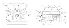
- FIG. 1shows a schematic top view of an agricultural combine 1 .
- the combine 1comprises a header 2 , which is connected to the front end of a combine body 3 .
- the back end of the combine body 3comprises a residue spreading system 4 .
- the header 2cuts the crop material from the field, and draws the crop material into the body 3 of the combine 1 .
- the crop materialis processed to separate the harvest from the residue.
- the residueis then transported, inside the body 3 of the combine 1 , to the residue spreading system 4 , which throws the residue onto the field.
- the residue spreading system 4is conventionally configured to approach a situation wherein the residue is evenly distributed on the field over a width that is equal to the width of the header 2 .
- the distribution of the residue on the fieldis adaptable by steering the residue spreading system 4 .
- residue spreading systems 4 according to the prior artcan be steered to influence the residue distribution, for example to compensate for external influences such as wind so that an even distribution can be obtained in multiple circumstances.
- the force/speed with which the residue spreading system 4 throws the residue out of the back end of the agricultural combine 1can be adjusted.
- the angular range over which the residue spreading system 4 spreads the residuecan also be adjusted.
- the residue spreading system 4typically comprises multiple (at least a left and a right) of such adjustable mechanisms 10 , 10 ′ for throwing the residue out of the back end of the combine 1 . This allows to change the distribution of residue over the field by adapting the residue spreading system 4 . Since such mechanisms 10 , 10 ′ are known in the prior art, no further specifications are given regarding such residue spreading system since the skilled person knows these systems and will know how such systems can be steered to adapt the residue distribution.
- FIG. 1the agricultural combine is illustrated in operation, wherein residue is expelled from the combine.
- the expelled residuehas two parts, referred to with reference numbers 5 and 13 respectively.
- the cloud 5illustrates the straw that is expelled by the residue spreading system and the cloud 13 illustrates the chaff that is expelled by the residue spreading system.
- Chaff and straware separated from the harvest in the body 3 of the agricultural combine 1 using different techniques.
- many residue spreading systemscomprise separate spreaders for chaff and straw, explaining the chaff cloud 13 located at a distance from the straw cloud 5 .
- FIG. 2illustrates the principles of processing crop material inside a body 3 of an agricultural combine 1 .
- Reference number 6illustrates the threshing process of the crop material that is cut from the field via the header 2 .
- the smaller partssuch as the harvest particles and the chaff particles are separated from larger crop material elements such as straw.
- These larger elementsare chopped by a chopper 9 and subsequently expelled at the back end of the agricultural combine 1 .
- the strawcan be expelled via residue spreading discs 10 or via fins.
- the smaller particlesare further processed, as is illustrated with reference number 7 , to separate the harvest particles from the chaff particles.
- These chaff particlesare collected as is illustrated with arrow 11 , in a chaff spreader 12 .
- the chaff spreader 12distributes the chaff onto the field separately from the straw spreader 8 .
- FIG. 3shows a first embodiment of the chaff spreader 12 of the invention.
- the chaff spreader 12comprises an upper segment 14 and a lower segment 15 .
- the upper segment 14is located directly adjacent the lower segment 15 .
- the upper segment 14embodies a first chaff accelerator while the lower segment 15 embodies a second chaff accelerator.
- the upper segment 14 of the chaff spreader 12comprises a cylindrically shaped housing 16 which is open at the top so that chaff can fall into the housing 16 , which is illustrated in FIG. 3 with arrows 11 .
- the upper segment 14further comprises a rotor with multiple rotor blades 17 , driven by a motor 24 so that the chaff that falls into the housing is accelerated by the rotor and rotor blades.
- the upper segment 14 of the chaff spreader 12is connected to the lower segment 15 of the spreader 12 via a chaff transporting channel 18 .
- the chaff transporting channel 18connects an opening at a side of the upper segment housing 16 with a further opening at a side of the lower section 15 .
- the opening at the upper section 14is considered an upper outlet opening since chaff particles are removed from the housing 16 via that opening, as is illustrated with arrow 19 .
- the further opening at the lower section 15is considered a lower inlet opening of the lower section 15 since chaff particles are introduced in this lower section 15 via this further opening.
- the lower section 15also comprises a cylindrical housing 20 , with a diameter that is preferably substantially the same as the diameter of the cylindrical upper housing 16 .
- the lower segment 15further comprises a rotor having multiple rotor blades 21 , analogue to the rotor with rotor blades at the upper segment 14 .
- the lower segment 15further comprises grinding elements 22 , 23 , in FIG. 3 showed as hammers 22 and a shred bar 23 .
- the rotor with the rotor blades and the grinding elements 22 at the lower segment 15are also driven by a motor 24 .
- the lower segment 15further comprises a lower outlet opening 25 into the housing 20 , which lower outlet opening is formed at a side of the housing 20 so that the chaff can be ejected from the spreader 12 via the outlet opening 25 . This is illustrated with arrows 13 .
- the motor 24is configured to drive the upper rotor at a first speed and the lower rotor at a second speed that is higher than the first speed.
- Thisis preferably realized via a single motor and a gear box, for example a planetary gear box as is shown in FIG. 5 .
- the skilled personwill understand how two rotors can be driven at different speeds at a single motor and a gear box, and therefore this aspect is not described in more detail.
- FIG. 4shows a top view of the lower chamber 20 of the chaff spreader.
- This top viewillustrates how the chaff transporting channel 18 can be formed outside of the periphery of the rotors and in such a manner that the chaff can be optimally guided from an upper outlet at the upper segment to a lower inlet at the lower segment.
- Thisis realized in the embodiment of FIG. 4 by shaping the chaff transporting channel with a curvature that is chosen to bend the outgoing flow of chaff particles of the upper segment to an ingoing flow at the lower segment. Such flow is illustrated in FIG. 4 with arrow 19 .
- FIG. 4shows a top view of the lower chamber 20 of the chaff spreader.
- the 4furthermore shows the rotor with the multiple rotor blades 21 , which ensure that the chaff particles are forced to follow the rotor speed, and comprising multiple hammers 22 , preferably comprising a hinge 26 so that the outer ends of the hammers 22 can pivot with respect to the hinge 26 .
- the hammersDue to the rotation of the rotor, the hammers will be forced to the periphery of the chamber 20 , thereby hitting against or moving at least close to shred bars 23 .
- the chaff particlesare ground between the hammers and the shred bars. Any seed element or crop element is crushed.
- the lower segment 20further comprises a lower opening 25 so that the chaff can be expelled 13 .
- multiple hammer set-upscan be designed and that one or more shred bars 23 can be provided, that the number of hammers 22 and/or rotor blades 21 can be chosen depending on multiple factors.
- the chaff transporting channel 18is shown in a position where it covers the upper outlet of the upper segment 14 as well as the lower inlet of the lower segment 15 .
- This chaff transporting channel 18can be mounted in a displaceable manner, so that when the chaff transporting channel is displaced, the chaff transporting channel 18 does not cover the upper outlet of the upper segment 14 .
- chaffwill be expelled directly by the upper segment, the lower segment is bypassed, and no grinding by the lower segment occurs.
- Such chaff transporting channel 18could allow the farmer or operator of the agricultural vehicle to choose the processing settings, particularly whether grinding is preferred or not.
- FIG. 5shows an alternative embodiment of the invention wherein the lower segment 15 and the upper segment 14 are not positioned directly adjacent to each other, and wherein the chaff transporting channel 18 bridges the gap between the upper segment 14 and the lower segment 15 .
- the advantage of such set-upis that the chaff transporting channel 18 can be completely formed within the periphery of the upper and lower cylindrical bodies 16 , 20 .
- the upper outlet openingis formed at a bottom of the upper chamber
- the lower inlet openingis formed at a top of the lower chamber.
- the further operational characteristics of the embodiment of FIG. 5are substantially the same or at least analogue as described above in relation to FIGS. 3 and 4 .
- FIG. 5shows the motor 24 and the gear box 27 in more detail. Thereby, the figure shows how the shaft of the motor is directly connected to the upper rotor of the upper segment 14 . Furthermore, planetary gears are connected to the frame and a sun gear 30 is connected to the lower rotor of the lower segment 15 . The ring gear 28 can be coupled to the motor shaft via a coupling element 31 . This is illustrated by arrow 32 , wherein the upper position of the coupling element 31 interconnects the ring gear with the central shaft and a lower position disconnects the ring gear 28 from the central shaft of the motor.
- the housing 16 , 20as cylindrical. It is noted that the term cylindrical points to the visual impression that this housings generates, and not to the mathematical shape thereof. In practice, the housing is a bit eccentric so that near the outlet, the distance of the rotor to the housing is a bit bigger to prevent blockage by pinching of the chaff between the rotor and the housing. Therefore the term cylindrical is not intended to limit the scope of protection, but rather to give a more general impression of the principles of the invention.
Landscapes
- Life Sciences & Earth Sciences (AREA)
- Environmental Sciences (AREA)
- Catching Or Destruction (AREA)
- Threshing Machine Elements (AREA)
Abstract
Description
Claims (14)
Applications Claiming Priority (2)
| Application Number | Priority Date | Filing Date | Title |
|---|---|---|---|
| BE2016/5126 | 2016-02-23 | ||
| BE2016/5126ABE1023485B1 (en) | 2016-02-23 | 2016-02-23 | CHAIN SPREADER WITH SEED BUGS |
Publications (2)
| Publication Number | Publication Date |
|---|---|
| US20170238463A1 US20170238463A1 (en) | 2017-08-24 |
| US10426086B2true US10426086B2 (en) | 2019-10-01 |
Family
ID=55966949
Family Applications (1)
| Application Number | Title | Priority Date | Filing Date |
|---|---|---|---|
| US15/440,467ActiveUS10426086B2 (en) | 2016-02-23 | 2017-02-23 | Chaff spreader with seed bruising |
Country Status (4)
| Country | Link |
|---|---|
| US (1) | US10426086B2 (en) |
| EP (1) | EP3210457B1 (en) |
| BE (1) | BE1023485B1 (en) |
| BR (1) | BR102017003422B1 (en) |
Cited By (57)
| Publication number | Priority date | Publication date | Assignee | Title |
|---|---|---|---|---|
| US20210022289A1 (en)* | 2018-03-22 | 2021-01-28 | Seed Terminator Holdings PTY LTD | An impact mill and a residue processing system incorporating same |
| US10986778B2 (en)* | 2018-10-31 | 2021-04-27 | Deere & Company | Weed seed devitalizer control |
| US11079725B2 (en) | 2019-04-10 | 2021-08-03 | Deere & Company | Machine control using real-time model |
| US11178818B2 (en) | 2018-10-26 | 2021-11-23 | Deere & Company | Harvesting machine control system with fill level processing based on yield data |
| US11206763B2 (en)* | 2018-10-31 | 2021-12-28 | Deere & Company | Weed seed based harvester working member control |
| US11234366B2 (en) | 2019-04-10 | 2022-02-01 | Deere & Company | Image selection for machine control |
| US11240961B2 (en) | 2018-10-26 | 2022-02-08 | Deere & Company | Controlling a harvesting machine based on a geo-spatial representation indicating where the harvesting machine is likely to reach capacity |
| US20220110251A1 (en) | 2020-10-09 | 2022-04-14 | Deere & Company | Crop moisture map generation and control system |
| US11467605B2 (en) | 2019-04-10 | 2022-10-11 | Deere & Company | Zonal machine control |
| US11474523B2 (en) | 2020-10-09 | 2022-10-18 | Deere & Company | Machine control using a predictive speed map |
| US11477940B2 (en) | 2020-03-26 | 2022-10-25 | Deere & Company | Mobile work machine control based on zone parameter modification |
| US11589509B2 (en) | 2018-10-26 | 2023-02-28 | Deere & Company | Predictive machine characteristic map generation and control system |
| US11592822B2 (en) | 2020-10-09 | 2023-02-28 | Deere & Company | Machine control using a predictive map |
| US11635765B2 (en) | 2020-10-09 | 2023-04-25 | Deere & Company | Crop state map generation and control system |
| US11641800B2 (en) | 2020-02-06 | 2023-05-09 | Deere & Company | Agricultural harvesting machine with pre-emergence weed detection and mitigation system |
| US11650587B2 (en) | 2020-10-09 | 2023-05-16 | Deere & Company | Predictive power map generation and control system |
| US11653588B2 (en) | 2018-10-26 | 2023-05-23 | Deere & Company | Yield map generation and control system |
| US11672203B2 (en) | 2018-10-26 | 2023-06-13 | Deere & Company | Predictive map generation and control |
| US11675354B2 (en) | 2020-10-09 | 2023-06-13 | Deere & Company | Machine control using a predictive map |
| US11711995B2 (en) | 2020-10-09 | 2023-08-01 | Deere & Company | Machine control using a predictive map |
| US11727680B2 (en) | 2020-10-09 | 2023-08-15 | Deere & Company | Predictive map generation based on seeding characteristics and control |
| US11825768B2 (en) | 2020-10-09 | 2023-11-28 | Deere & Company | Machine control using a predictive map |
| US11845449B2 (en) | 2020-10-09 | 2023-12-19 | Deere & Company | Map generation and control system |
| US11844311B2 (en) | 2020-10-09 | 2023-12-19 | Deere & Company | Machine control using a predictive map |
| US11849671B2 (en) | 2020-10-09 | 2023-12-26 | Deere & Company | Crop state map generation and control system |
| US11849672B2 (en) | 2020-10-09 | 2023-12-26 | Deere & Company | Machine control using a predictive map |
| US11864483B2 (en) | 2020-10-09 | 2024-01-09 | Deere & Company | Predictive map generation and control system |
| US11874669B2 (en) | 2020-10-09 | 2024-01-16 | Deere & Company | Map generation and control system |
| US11889788B2 (en) | 2020-10-09 | 2024-02-06 | Deere & Company | Predictive biomass map generation and control |
| US11889787B2 (en) | 2020-10-09 | 2024-02-06 | Deere & Company | Predictive speed map generation and control system |
| US11895948B2 (en) | 2020-10-09 | 2024-02-13 | Deere & Company | Predictive map generation and control based on soil properties |
| US11927459B2 (en) | 2020-10-09 | 2024-03-12 | Deere & Company | Machine control using a predictive map |
| US11946747B2 (en) | 2020-10-09 | 2024-04-02 | Deere & Company | Crop constituent map generation and control system |
| US11957072B2 (en) | 2020-02-06 | 2024-04-16 | Deere & Company | Pre-emergence weed detection and mitigation system |
| US11983009B2 (en) | 2020-10-09 | 2024-05-14 | Deere & Company | Map generation and control system |
| US12013245B2 (en) | 2020-10-09 | 2024-06-18 | Deere & Company | Predictive map generation and control system |
| US12035648B2 (en) | 2020-02-06 | 2024-07-16 | Deere & Company | Predictive weed map generation and control system |
| US12058951B2 (en) | 2022-04-08 | 2024-08-13 | Deere & Company | Predictive nutrient map and control |
| US12069986B2 (en) | 2020-10-09 | 2024-08-27 | Deere & Company | Map generation and control system |
| US12069978B2 (en) | 2018-10-26 | 2024-08-27 | Deere & Company | Predictive environmental characteristic map generation and control system |
| US12082531B2 (en) | 2022-01-26 | 2024-09-10 | Deere & Company | Systems and methods for predicting material dynamics |
| US12127500B2 (en) | 2021-01-27 | 2024-10-29 | Deere & Company | Machine control using a map with regime zones |
| US12178158B2 (en) | 2020-10-09 | 2024-12-31 | Deere & Company | Predictive map generation and control system for an agricultural work machine |
| US12225846B2 (en) | 2020-02-06 | 2025-02-18 | Deere & Company | Machine control using a predictive map |
| US12229886B2 (en) | 2021-10-01 | 2025-02-18 | Deere & Company | Historical crop state model, predictive crop state map generation and control system |
| US12245549B2 (en) | 2022-01-11 | 2025-03-11 | Deere & Company | Predictive response map generation and control system |
| US12250905B2 (en) | 2020-10-09 | 2025-03-18 | Deere & Company | Machine control using a predictive map |
| US12284934B2 (en) | 2022-04-08 | 2025-04-29 | Deere & Company | Systems and methods for predictive tractive characteristics and control |
| US12298767B2 (en) | 2022-04-08 | 2025-05-13 | Deere & Company | Predictive material consumption map and control |
| US12295288B2 (en) | 2022-04-05 | 2025-05-13 | Deere &Company | Predictive machine setting map generation and control system |
| US12302791B2 (en) | 2021-12-20 | 2025-05-20 | Deere & Company | Crop constituents, predictive mapping, and agricultural harvester control |
| US12310286B2 (en) | 2021-12-14 | 2025-05-27 | Deere & Company | Crop constituent sensing |
| US12329148B2 (en) | 2020-02-06 | 2025-06-17 | Deere & Company | Predictive weed map and material application machine control |
| US12358493B2 (en) | 2022-04-08 | 2025-07-15 | Deere & Company | Systems and methods for predictive power requirements and control |
| US12386354B2 (en) | 2020-10-09 | 2025-08-12 | Deere & Company | Predictive power map generation and control system |
| US12419220B2 (en) | 2020-10-09 | 2025-09-23 | Deere & Company | Predictive map generation and control system |
| US12422847B2 (en) | 2020-10-09 | 2025-09-23 | Deere & Company | Predictive agricultural model and map generation |
Families Citing this family (9)
| Publication number | Priority date | Publication date | Assignee | Title |
|---|---|---|---|---|
| CA3158924A1 (en)* | 2015-07-14 | 2017-01-19 | Tritana Intellectual Property Ltd. | Weed seed destruction rotor and stator shape |
| US10492369B2 (en)* | 2015-07-14 | 2019-12-03 | Dean Mayerle | Weed seed destruction |
| US20230141301A1 (en)* | 2018-02-01 | 2023-05-11 | Dean Mayerle | Weed Seed Destruction |
| EP3937611B1 (en)* | 2019-03-14 | 2025-08-13 | Tritana Intellectual Property Ltd. | Weed seed destruction |
| US20230337588A1 (en) | 2019-03-14 | 2023-10-26 | Tritana Intellectual Property Ltd. | Weed seed destruction |
| US11510364B2 (en) | 2019-07-19 | 2022-11-29 | Deere & Company | Crop residue based field operation adjustment |
| US11758847B2 (en) | 2019-09-19 | 2023-09-19 | Deere & Company | Residue quality assessment and performance system for a harvester |
| WO2021179059A1 (en) | 2020-03-12 | 2021-09-16 | Mayerle, Dean | Weed seed destruction |
| US12310285B2 (en) | 2023-02-27 | 2025-05-27 | Deere & Company | Agricultural operation evaluation system and method |
Citations (32)
| Publication number | Priority date | Publication date | Assignee | Title |
|---|---|---|---|---|
| FR1095015A (en)* | 1952-12-19 | 1955-05-26 | Device for cutting straw, hay, or other agricultural products, and comprising rotary cutting tools and counter-cutting edges arranged in the suction line of a blower | |
| US4062366A (en)* | 1975-06-26 | 1977-12-13 | Sperry Rand Corporation | Rethresher |
| US4292795A (en)* | 1979-11-19 | 1981-10-06 | Linn Orville J | Straw and chaff chopper and spreader |
| DE3540493C1 (en) | 1985-11-15 | 1987-04-23 | Engelbrecht & Lemmerbrock | Combine harvester with screening out of weeds |
| US4684068A (en) | 1986-01-17 | 1987-08-04 | Deutz-Allis Corporation | Dual rotating spreaders for harvester discharge |
| US4836456A (en) | 1984-08-17 | 1989-06-06 | Lely Cornelis V D | Agricultural spreader having multiple distribution members broadcasting material simultaneously to generally the same area |
| US5082186A (en) | 1989-11-29 | 1992-01-21 | Bruns Mark W | Chaff spreader |
| US5556042A (en)* | 1994-09-07 | 1996-09-17 | Claas Ohg Beschrankt Haftende Offene Handelsgesellschaft | Combine chopper attachment with pivotal broadcast discharge chute |
| WO1997010701A1 (en)* | 1995-09-19 | 1997-03-27 | Rekordverken Sweden Ab | Spreader |
| DE19750393A1 (en) | 1997-11-14 | 1998-04-30 | Jakobi Wilhelm Dipl Ing Fh | Device for collecting and distributing chaff in thresher machines |
| FR2776468A1 (en) | 1998-03-27 | 1999-10-01 | Alain Bernard | Grinder for destroying unwanted material from sorting table of thresher, |
| US5976011A (en)* | 1997-12-31 | 1999-11-02 | Hartman; Everett A. | Straw and chaff spreader assembly |
| US6070816A (en)* | 1997-12-02 | 2000-06-06 | Deere & Company | Straw chopper |
| EP1027820A1 (en) | 1999-02-09 | 2000-08-16 | Franz Schrattenecker | Chaffspreader for a combine |
| AU3878101A (en) | 2000-04-20 | 2001-10-25 | Harvestaire Pty Ltd | Harvest residue destruction system |
| US20020073675A1 (en)* | 2000-12-20 | 2002-06-20 | Deere & Company | Chopper arrangement |
| US6500064B1 (en)* | 1998-05-19 | 2002-12-31 | Franz Schrattenecker | Chaff distributor for a combine harvester |
| US20030109294A1 (en)* | 2001-12-12 | 2003-06-12 | Wolters Joshua J. | Vertical crop residue chopper and spreader |
| WO2005041639A1 (en) | 2003-10-28 | 2005-05-12 | Georg-August Universität Göttingen | Chopping device for a combine harvester |
| US20050124399A1 (en)* | 2002-02-27 | 2005-06-09 | Bengt Holmen | Combine chaff discharger |
| US7306174B2 (en) | 2004-03-04 | 2007-12-11 | Deere & Company | Broadcast width and location control for a combine spreader |
| EP1897430A1 (en) | 2006-09-07 | 2008-03-12 | CLAAS Selbstfahrende Erntemaschinen GmbH | Shredder and distribution device |
| DE102007005173A1 (en) | 2007-01-29 | 2008-08-14 | Claas Selbstfahrende Erntemaschinen Gmbh | Harvester, has straw guiding unit surrounding guiding roller in goods flow direction, where unit is arranged in position with gap parallel to guiding roller, such that unit causes compression of goods matte in combination with roller |
| US20110070934A1 (en) | 2009-09-21 | 2011-03-24 | Stefan Teroerde | Method for distributing a material flow onto a field, and chopping and spreading device |
| WO2012022293A1 (en) | 2010-07-23 | 2012-02-23 | Wagner Alfred Eisenhandel | Device on combine-harvesters and combine-harvester with a device of this type |
| US8152610B2 (en) | 2008-02-13 | 2012-04-10 | Grains Research And Development Corporation | Weed and volunteer crop seed destruction |
| WO2013087423A1 (en) | 2011-12-14 | 2013-06-20 | Thomas Nehls | Chaff conditioning and distributing device |
| US20150373913A1 (en) | 2013-02-19 | 2015-12-31 | University Of South Australia | Weed seed devitalization arrangement |
| US20160150728A1 (en) | 2013-05-08 | 2016-06-02 | Cnh Industrial America Llc | Combine Harvester with Improved Chopper and Spreader Arrangement |
| US20170034997A1 (en)* | 2015-07-14 | 2017-02-09 | Dean Mayerle | Weed Seed Destruction |
| US9730390B2 (en)* | 2015-06-23 | 2017-08-15 | Cnh Industrial America Llc | Chaff spread assisted by cross-blown airflow |
| US20180070534A1 (en)* | 2015-07-14 | 2018-03-15 | Dean Mayerle | Weed Seed Destruction |
- 2016
- 2016-02-23BEBE2016/5126Apatent/BE1023485B1/enactive
- 2017
- 2017-02-21BRBR102017003422-4Apatent/BR102017003422B1/enactiveIP Right Grant
- 2017-02-23USUS15/440,467patent/US10426086B2/enactiveActive
- 2017-02-23EPEP17157544.2Apatent/EP3210457B1/enactiveActive
Patent Citations (34)
| Publication number | Priority date | Publication date | Assignee | Title |
|---|---|---|---|---|
| FR1095015A (en)* | 1952-12-19 | 1955-05-26 | Device for cutting straw, hay, or other agricultural products, and comprising rotary cutting tools and counter-cutting edges arranged in the suction line of a blower | |
| US4062366A (en)* | 1975-06-26 | 1977-12-13 | Sperry Rand Corporation | Rethresher |
| US4292795A (en)* | 1979-11-19 | 1981-10-06 | Linn Orville J | Straw and chaff chopper and spreader |
| US4836456A (en) | 1984-08-17 | 1989-06-06 | Lely Cornelis V D | Agricultural spreader having multiple distribution members broadcasting material simultaneously to generally the same area |
| DE3540493C1 (en) | 1985-11-15 | 1987-04-23 | Engelbrecht & Lemmerbrock | Combine harvester with screening out of weeds |
| US4684068A (en) | 1986-01-17 | 1987-08-04 | Deutz-Allis Corporation | Dual rotating spreaders for harvester discharge |
| US5082186A (en) | 1989-11-29 | 1992-01-21 | Bruns Mark W | Chaff spreader |
| US5556042A (en)* | 1994-09-07 | 1996-09-17 | Claas Ohg Beschrankt Haftende Offene Handelsgesellschaft | Combine chopper attachment with pivotal broadcast discharge chute |
| WO1997010701A1 (en)* | 1995-09-19 | 1997-03-27 | Rekordverken Sweden Ab | Spreader |
| DE19750393A1 (en) | 1997-11-14 | 1998-04-30 | Jakobi Wilhelm Dipl Ing Fh | Device for collecting and distributing chaff in thresher machines |
| US6070816A (en)* | 1997-12-02 | 2000-06-06 | Deere & Company | Straw chopper |
| US5976011A (en)* | 1997-12-31 | 1999-11-02 | Hartman; Everett A. | Straw and chaff spreader assembly |
| FR2776468A1 (en) | 1998-03-27 | 1999-10-01 | Alain Bernard | Grinder for destroying unwanted material from sorting table of thresher, |
| US6500064B1 (en)* | 1998-05-19 | 2002-12-31 | Franz Schrattenecker | Chaff distributor for a combine harvester |
| EP1027820A1 (en) | 1999-02-09 | 2000-08-16 | Franz Schrattenecker | Chaffspreader for a combine |
| AU3878101A (en) | 2000-04-20 | 2001-10-25 | Harvestaire Pty Ltd | Harvest residue destruction system |
| US20020073675A1 (en)* | 2000-12-20 | 2002-06-20 | Deere & Company | Chopper arrangement |
| US6688971B2 (en)* | 2000-12-20 | 2004-02-10 | Deere & Company | Chopper arrangement |
| US20030109294A1 (en)* | 2001-12-12 | 2003-06-12 | Wolters Joshua J. | Vertical crop residue chopper and spreader |
| US20050124399A1 (en)* | 2002-02-27 | 2005-06-09 | Bengt Holmen | Combine chaff discharger |
| WO2005041639A1 (en) | 2003-10-28 | 2005-05-12 | Georg-August Universität Göttingen | Chopping device for a combine harvester |
| US7306174B2 (en) | 2004-03-04 | 2007-12-11 | Deere & Company | Broadcast width and location control for a combine spreader |
| EP1897430A1 (en) | 2006-09-07 | 2008-03-12 | CLAAS Selbstfahrende Erntemaschinen GmbH | Shredder and distribution device |
| DE102007005173A1 (en) | 2007-01-29 | 2008-08-14 | Claas Selbstfahrende Erntemaschinen Gmbh | Harvester, has straw guiding unit surrounding guiding roller in goods flow direction, where unit is arranged in position with gap parallel to guiding roller, such that unit causes compression of goods matte in combination with roller |
| US8152610B2 (en) | 2008-02-13 | 2012-04-10 | Grains Research And Development Corporation | Weed and volunteer crop seed destruction |
| US20110070934A1 (en) | 2009-09-21 | 2011-03-24 | Stefan Teroerde | Method for distributing a material flow onto a field, and chopping and spreading device |
| US8105140B2 (en)* | 2009-09-21 | 2012-01-31 | Claas Selbstfahrende Erntemaschinen Gmbh | Method for distributing a material flow onto a field, and chopping and spreading device |
| WO2012022293A1 (en) | 2010-07-23 | 2012-02-23 | Wagner Alfred Eisenhandel | Device on combine-harvesters and combine-harvester with a device of this type |
| WO2013087423A1 (en) | 2011-12-14 | 2013-06-20 | Thomas Nehls | Chaff conditioning and distributing device |
| US20150373913A1 (en) | 2013-02-19 | 2015-12-31 | University Of South Australia | Weed seed devitalization arrangement |
| US20160150728A1 (en) | 2013-05-08 | 2016-06-02 | Cnh Industrial America Llc | Combine Harvester with Improved Chopper and Spreader Arrangement |
| US9730390B2 (en)* | 2015-06-23 | 2017-08-15 | Cnh Industrial America Llc | Chaff spread assisted by cross-blown airflow |
| US20170034997A1 (en)* | 2015-07-14 | 2017-02-09 | Dean Mayerle | Weed Seed Destruction |
| US20180070534A1 (en)* | 2015-07-14 | 2018-03-15 | Dean Mayerle | Weed Seed Destruction |
Cited By (70)
| Publication number | Priority date | Publication date | Assignee | Title |
|---|---|---|---|---|
| US12396395B2 (en)* | 2018-03-22 | 2025-08-26 | Seed Terminator Holdings PTY LTD | Impact mill and a residue processing system incorporating same |
| US20210022289A1 (en)* | 2018-03-22 | 2021-01-28 | Seed Terminator Holdings PTY LTD | An impact mill and a residue processing system incorporating same |
| US11672203B2 (en) | 2018-10-26 | 2023-06-13 | Deere & Company | Predictive map generation and control |
| US11178818B2 (en) | 2018-10-26 | 2021-11-23 | Deere & Company | Harvesting machine control system with fill level processing based on yield data |
| US12010947B2 (en) | 2018-10-26 | 2024-06-18 | Deere & Company | Predictive machine characteristic map generation and control system |
| US12069978B2 (en) | 2018-10-26 | 2024-08-27 | Deere & Company | Predictive environmental characteristic map generation and control system |
| US11240961B2 (en) | 2018-10-26 | 2022-02-08 | Deere & Company | Controlling a harvesting machine based on a geo-spatial representation indicating where the harvesting machine is likely to reach capacity |
| US11653588B2 (en) | 2018-10-26 | 2023-05-23 | Deere & Company | Yield map generation and control system |
| US12171153B2 (en) | 2018-10-26 | 2024-12-24 | Deere & Company | Yield map generation and control system |
| US11589509B2 (en) | 2018-10-26 | 2023-02-28 | Deere & Company | Predictive machine characteristic map generation and control system |
| US12178156B2 (en) | 2018-10-26 | 2024-12-31 | Deere & Company | Predictive map generation and control |
| US10986778B2 (en)* | 2018-10-31 | 2021-04-27 | Deere & Company | Weed seed devitalizer control |
| US11206763B2 (en)* | 2018-10-31 | 2021-12-28 | Deere & Company | Weed seed based harvester working member control |
| US11650553B2 (en) | 2019-04-10 | 2023-05-16 | Deere & Company | Machine control using real-time model |
| US11467605B2 (en) | 2019-04-10 | 2022-10-11 | Deere & Company | Zonal machine control |
| US11079725B2 (en) | 2019-04-10 | 2021-08-03 | Deere & Company | Machine control using real-time model |
| US11234366B2 (en) | 2019-04-10 | 2022-02-01 | Deere & Company | Image selection for machine control |
| US11829112B2 (en) | 2019-04-10 | 2023-11-28 | Deere & Company | Machine control using real-time model |
| US11641800B2 (en) | 2020-02-06 | 2023-05-09 | Deere & Company | Agricultural harvesting machine with pre-emergence weed detection and mitigation system |
| US12329148B2 (en) | 2020-02-06 | 2025-06-17 | Deere & Company | Predictive weed map and material application machine control |
| US12225846B2 (en) | 2020-02-06 | 2025-02-18 | Deere & Company | Machine control using a predictive map |
| US12035648B2 (en) | 2020-02-06 | 2024-07-16 | Deere & Company | Predictive weed map generation and control system |
| US11957072B2 (en) | 2020-02-06 | 2024-04-16 | Deere & Company | Pre-emergence weed detection and mitigation system |
| US11477940B2 (en) | 2020-03-26 | 2022-10-25 | Deere & Company | Mobile work machine control based on zone parameter modification |
| US11927459B2 (en) | 2020-10-09 | 2024-03-12 | Deere & Company | Machine control using a predictive map |
| US12271196B2 (en) | 2020-10-09 | 2025-04-08 | Deere &Company | Machine control using a predictive map |
| US11849671B2 (en) | 2020-10-09 | 2023-12-26 | Deere & Company | Crop state map generation and control system |
| US11849672B2 (en) | 2020-10-09 | 2023-12-26 | Deere & Company | Machine control using a predictive map |
| US11864483B2 (en) | 2020-10-09 | 2024-01-09 | Deere & Company | Predictive map generation and control system |
| US11871697B2 (en) | 2020-10-09 | 2024-01-16 | Deere & Company | Crop moisture map generation and control system |
| US11874669B2 (en) | 2020-10-09 | 2024-01-16 | Deere & Company | Map generation and control system |
| US11889788B2 (en) | 2020-10-09 | 2024-02-06 | Deere & Company | Predictive biomass map generation and control |
| US11889787B2 (en) | 2020-10-09 | 2024-02-06 | Deere & Company | Predictive speed map generation and control system |
| US11895948B2 (en) | 2020-10-09 | 2024-02-13 | Deere & Company | Predictive map generation and control based on soil properties |
| US11845449B2 (en) | 2020-10-09 | 2023-12-19 | Deere & Company | Map generation and control system |
| US11946747B2 (en) | 2020-10-09 | 2024-04-02 | Deere & Company | Crop constituent map generation and control system |
| US11825768B2 (en) | 2020-10-09 | 2023-11-28 | Deere & Company | Machine control using a predictive map |
| US11983009B2 (en) | 2020-10-09 | 2024-05-14 | Deere & Company | Map generation and control system |
| US12013245B2 (en) | 2020-10-09 | 2024-06-18 | Deere & Company | Predictive map generation and control system |
| US11727680B2 (en) | 2020-10-09 | 2023-08-15 | Deere & Company | Predictive map generation based on seeding characteristics and control |
| US12013698B2 (en) | 2020-10-09 | 2024-06-18 | Deere & Company | Machine control using a predictive map |
| US11711995B2 (en) | 2020-10-09 | 2023-08-01 | Deere & Company | Machine control using a predictive map |
| US12048271B2 (en) | 2020-10-09 | 2024-07-30 | Deere &Company | Crop moisture map generation and control system |
| US12422847B2 (en) | 2020-10-09 | 2025-09-23 | Deere & Company | Predictive agricultural model and map generation |
| US12069986B2 (en) | 2020-10-09 | 2024-08-27 | Deere & Company | Map generation and control system |
| US11675354B2 (en) | 2020-10-09 | 2023-06-13 | Deere & Company | Machine control using a predictive map |
| US12080062B2 (en) | 2020-10-09 | 2024-09-03 | Deere & Company | Predictive map generation based on seeding characteristics and control |
| US12419220B2 (en) | 2020-10-09 | 2025-09-23 | Deere & Company | Predictive map generation and control system |
| US20220110251A1 (en) | 2020-10-09 | 2022-04-14 | Deere & Company | Crop moisture map generation and control system |
| US11650587B2 (en) | 2020-10-09 | 2023-05-16 | Deere & Company | Predictive power map generation and control system |
| US11635765B2 (en) | 2020-10-09 | 2023-04-25 | Deere & Company | Crop state map generation and control system |
| US12178158B2 (en) | 2020-10-09 | 2024-12-31 | Deere & Company | Predictive map generation and control system for an agricultural work machine |
| US12193350B2 (en) | 2020-10-09 | 2025-01-14 | Deere & Company | Machine control using a predictive map |
| US12216472B2 (en) | 2020-10-09 | 2025-02-04 | Deere & Company | Map generation and control system |
| US11592822B2 (en) | 2020-10-09 | 2023-02-28 | Deere & Company | Machine control using a predictive map |
| US12386354B2 (en) | 2020-10-09 | 2025-08-12 | Deere & Company | Predictive power map generation and control system |
| US11474523B2 (en) | 2020-10-09 | 2022-10-18 | Deere & Company | Machine control using a predictive speed map |
| US12250905B2 (en) | 2020-10-09 | 2025-03-18 | Deere & Company | Machine control using a predictive map |
| US11844311B2 (en) | 2020-10-09 | 2023-12-19 | Deere & Company | Machine control using a predictive map |
| US12127500B2 (en) | 2021-01-27 | 2024-10-29 | Deere & Company | Machine control using a map with regime zones |
| US12229886B2 (en) | 2021-10-01 | 2025-02-18 | Deere & Company | Historical crop state model, predictive crop state map generation and control system |
| US12310286B2 (en) | 2021-12-14 | 2025-05-27 | Deere & Company | Crop constituent sensing |
| US12302791B2 (en) | 2021-12-20 | 2025-05-20 | Deere & Company | Crop constituents, predictive mapping, and agricultural harvester control |
| US12245549B2 (en) | 2022-01-11 | 2025-03-11 | Deere & Company | Predictive response map generation and control system |
| US12082531B2 (en) | 2022-01-26 | 2024-09-10 | Deere & Company | Systems and methods for predicting material dynamics |
| US12295288B2 (en) | 2022-04-05 | 2025-05-13 | Deere &Company | Predictive machine setting map generation and control system |
| US12284934B2 (en) | 2022-04-08 | 2025-04-29 | Deere & Company | Systems and methods for predictive tractive characteristics and control |
| US12298767B2 (en) | 2022-04-08 | 2025-05-13 | Deere & Company | Predictive material consumption map and control |
| US12358493B2 (en) | 2022-04-08 | 2025-07-15 | Deere & Company | Systems and methods for predictive power requirements and control |
| US12058951B2 (en) | 2022-04-08 | 2024-08-13 | Deere & Company | Predictive nutrient map and control |
Also Published As
| Publication number | Publication date |
|---|---|
| BR102017003422A2 (en) | 2017-08-29 |
| US20170238463A1 (en) | 2017-08-24 |
| EP3210457B1 (en) | 2020-02-12 |
| EP3210457A1 (en) | 2017-08-30 |
| BE1023485B1 (en) | 2017-04-06 |
| BR102017003422B1 (en) | 2022-04-12 |
Similar Documents
| Publication | Publication Date | Title |
|---|---|---|
| US10426086B2 (en) | Chaff spreader with seed bruising | |
| AU2020244587B2 (en) | Weed seed devitalization arrangement | |
| US12029161B2 (en) | Weed seed destruction rotor shape | |
| EP3590319B1 (en) | Weed seed destruction | |
| US6616528B2 (en) | Vertical crop residue chopper and spreader | |
| AU2018208625C1 (en) | Weed seed destruction | |
| EP3942917B1 (en) | Weed seed destruction | |
| RU2628445C2 (en) | Self-propelled combine harvester | |
| DE102015206845A1 (en) | Cutting unit for whole plant harvest | |
| DE10164954B4 (en) | Machine for mowing stalk-like crops | |
| DE102014102221A1 (en) | Method and control system for operating a forage harvester and forage harvester | |
| DE102010028599A1 (en) | Harvest crop shredder and distribution arrangement for a combine harvester | |
| AU2021221797A1 (en) | Tangential flow material processing chamber and associated material processing system | |
| BE1022956B1 (en) | Method and control device for operating a harvester | |
| EP2071934B1 (en) | Machine for harvesting stalk-like plants | |
| EP3984344B9 (en) | Improved agricultural machine for cutting and crushing residual materials | |
| ITVI20080298A1 (en) | AGRICULTURAL MACHINE PERFECTED FOR CUTTING AND CRUSHING RESIDUAL MATERIALS. | |
| AT13352U1 (en) | Mulcher |
Legal Events
| Date | Code | Title | Description |
|---|---|---|---|
| STPP | Information on status: patent application and granting procedure in general | Free format text:FINAL REJECTION MAILED | |
| STPP | Information on status: patent application and granting procedure in general | Free format text:NOTICE OF ALLOWANCE MAILED -- APPLICATION RECEIVED IN OFFICE OF PUBLICATIONS | |
| AS | Assignment | Owner name:CNH INDUSTRIAL BELGIUM NV, BELGIUM Free format text:ASSIGNMENT OF ASSIGNORS INTEREST;ASSIGNORS:BAES, FREDERIK;VAN DE WEGE, CHARLOTTE;VANDERGUCHT, YVAN C.C.;REEL/FRAME:049506/0732 Effective date:20160223 | |
| AS | Assignment | Owner name:CNH INDUSTRIAL AMERICA LLC, PENNSYLVANIA Free format text:ASSIGNMENT OF ASSIGNORS INTEREST;ASSIGNOR:CNH INDUSTRIAL BELGIUM NV;REEL/FRAME:049538/0039 Effective date:20170111 | |
| STPP | Information on status: patent application and granting procedure in general | Free format text:PUBLICATIONS -- ISSUE FEE PAYMENT VERIFIED | |
| STCF | Information on status: patent grant | Free format text:PATENTED CASE | |
| AS | Assignment | Owner name:BLUE LEAF I.P., INC., DELAWARE Free format text:ASSIGNMENT OF ASSIGNORS INTEREST;ASSIGNOR:CNH INDUSTRIAL AMERICA LLC;REEL/FRAME:052048/0914 Effective date:20200117 | |
| MAFP | Maintenance fee payment | Free format text:PAYMENT OF MAINTENANCE FEE, 4TH YEAR, LARGE ENTITY (ORIGINAL EVENT CODE: M1551); ENTITY STATUS OF PATENT OWNER: LARGE ENTITY Year of fee payment:4 |