US10425814B2 - Control of wireless communication device capability in a mobile device with a biometric key - Google Patents
Control of wireless communication device capability in a mobile device with a biometric keyDownload PDFInfo
- Publication number
- US10425814B2 US10425814B2US15/514,098US201515514098AUS10425814B2US 10425814 B2US10425814 B2US 10425814B2US 201515514098 AUS201515514098 AUS 201515514098AUS 10425814 B2US10425814 B2US 10425814B2
- Authority
- US
- United States
- Prior art keywords
- iris
- image
- illuminator
- wireless communication
- module
- Prior art date
- Legal status (The legal status is an assumption and is not a legal conclusion. Google has not performed a legal analysis and makes no representation as to the accuracy of the status listed.)
- Active, expires
Links
Images


Classifications
- A—HUMAN NECESSITIES
- A61—MEDICAL OR VETERINARY SCIENCE; HYGIENE
- A61B—DIAGNOSIS; SURGERY; IDENTIFICATION
- A61B3/00—Apparatus for testing the eyes; Instruments for examining the eyes
- A61B3/10—Objective types, i.e. instruments for examining the eyes independent of the patients' perceptions or reactions
- A61B3/12—Objective types, i.e. instruments for examining the eyes independent of the patients' perceptions or reactions for looking at the eye fundus, e.g. ophthalmoscopes
- A61B3/1216—Objective types, i.e. instruments for examining the eyes independent of the patients' perceptions or reactions for looking at the eye fundus, e.g. ophthalmoscopes for diagnostics of the iris
- H—ELECTRICITY
- H04—ELECTRIC COMMUNICATION TECHNIQUE
- H04W—WIRELESS COMMUNICATION NETWORKS
- H04W12/00—Security arrangements; Authentication; Protecting privacy or anonymity
- H04W12/06—Authentication
- A—HUMAN NECESSITIES
- A61—MEDICAL OR VETERINARY SCIENCE; HYGIENE
- A61B—DIAGNOSIS; SURGERY; IDENTIFICATION
- A61B5/00—Measuring for diagnostic purposes; Identification of persons
- A61B5/117—Identification of persons
- A61B5/1171—Identification of persons based on the shapes or appearances of their bodies or parts thereof
- G—PHYSICS
- G06—COMPUTING OR CALCULATING; COUNTING
- G06F—ELECTRIC DIGITAL DATA PROCESSING
- G06F21/00—Security arrangements for protecting computers, components thereof, programs or data against unauthorised activity
- G06F21/30—Authentication, i.e. establishing the identity or authorisation of security principals
- G06F21/31—User authentication
- G06F21/32—User authentication using biometric data, e.g. fingerprints, iris scans or voiceprints
- G—PHYSICS
- G06—COMPUTING OR CALCULATING; COUNTING
- G06F—ELECTRIC DIGITAL DATA PROCESSING
- G06F21/00—Security arrangements for protecting computers, components thereof, programs or data against unauthorised activity
- G06F21/70—Protecting specific internal or peripheral components, in which the protection of a component leads to protection of the entire computer
- G06F21/82—Protecting input, output or interconnection devices
- G06F21/83—Protecting input, output or interconnection devices input devices, e.g. keyboards, mice or controllers thereof
- G—PHYSICS
- G06—COMPUTING OR CALCULATING; COUNTING
- G06Q—INFORMATION AND COMMUNICATION TECHNOLOGY [ICT] SPECIALLY ADAPTED FOR ADMINISTRATIVE, COMMERCIAL, FINANCIAL, MANAGERIAL OR SUPERVISORY PURPOSES; SYSTEMS OR METHODS SPECIALLY ADAPTED FOR ADMINISTRATIVE, COMMERCIAL, FINANCIAL, MANAGERIAL OR SUPERVISORY PURPOSES, NOT OTHERWISE PROVIDED FOR
- G06Q20/00—Payment architectures, schemes or protocols
- G06Q20/08—Payment architectures
- G06Q20/10—Payment architectures specially adapted for electronic funds transfer [EFT] systems; specially adapted for home banking systems
- G06Q20/108—Remote banking, e.g. home banking
- G06Q20/1085—Remote banking, e.g. home banking involving automatic teller machines [ATMs]
- G—PHYSICS
- G06—COMPUTING OR CALCULATING; COUNTING
- G06Q—INFORMATION AND COMMUNICATION TECHNOLOGY [ICT] SPECIALLY ADAPTED FOR ADMINISTRATIVE, COMMERCIAL, FINANCIAL, MANAGERIAL OR SUPERVISORY PURPOSES; SYSTEMS OR METHODS SPECIALLY ADAPTED FOR ADMINISTRATIVE, COMMERCIAL, FINANCIAL, MANAGERIAL OR SUPERVISORY PURPOSES, NOT OTHERWISE PROVIDED FOR
- G06Q20/00—Payment architectures, schemes or protocols
- G06Q20/30—Payment architectures, schemes or protocols characterised by the use of specific devices or networks
- G06Q20/32—Payment architectures, schemes or protocols characterised by the use of specific devices or networks using wireless devices
- G06Q20/322—Aspects of commerce using mobile devices [M-devices]
- G—PHYSICS
- G06—COMPUTING OR CALCULATING; COUNTING
- G06Q—INFORMATION AND COMMUNICATION TECHNOLOGY [ICT] SPECIALLY ADAPTED FOR ADMINISTRATIVE, COMMERCIAL, FINANCIAL, MANAGERIAL OR SUPERVISORY PURPOSES; SYSTEMS OR METHODS SPECIALLY ADAPTED FOR ADMINISTRATIVE, COMMERCIAL, FINANCIAL, MANAGERIAL OR SUPERVISORY PURPOSES, NOT OTHERWISE PROVIDED FOR
- G06Q20/00—Payment architectures, schemes or protocols
- G06Q20/38—Payment protocols; Details thereof
- G06Q20/40—Authorisation, e.g. identification of payer or payee, verification of customer or shop credentials; Review and approval of payers, e.g. check credit lines or negative lists
- G06Q20/401—Transaction verification
- G06Q20/4014—Identity check for transactions
- G06Q20/40145—Biometric identity checks
- G—PHYSICS
- G06—COMPUTING OR CALCULATING; COUNTING
- G06V—IMAGE OR VIDEO RECOGNITION OR UNDERSTANDING
- G06V10/00—Arrangements for image or video recognition or understanding
- G06V10/40—Extraction of image or video features
- G06V10/44—Local feature extraction by analysis of parts of the pattern, e.g. by detecting edges, contours, loops, corners, strokes or intersections; Connectivity analysis, e.g. of connected components
- G—PHYSICS
- G06—COMPUTING OR CALCULATING; COUNTING
- G06V—IMAGE OR VIDEO RECOGNITION OR UNDERSTANDING
- G06V40/00—Recognition of biometric, human-related or animal-related patterns in image or video data
- G06V40/10—Human or animal bodies, e.g. vehicle occupants or pedestrians; Body parts, e.g. hands
- G06V40/18—Eye characteristics, e.g. of the iris
- G06V40/197—Matching; Classification
- G—PHYSICS
- G07—CHECKING-DEVICES
- G07F—COIN-FREED OR LIKE APPARATUS
- G07F19/00—Complete banking systems; Coded card-freed arrangements adapted for dispensing or receiving monies or the like and posting such transactions to existing accounts, e.g. automatic teller machines
- G07F19/20—Automatic teller machines [ATMs]
- G07F19/201—Accessories of ATMs
- H—ELECTRICITY
- H04—ELECTRIC COMMUNICATION TECHNIQUE
- H04L—TRANSMISSION OF DIGITAL INFORMATION, e.g. TELEGRAPHIC COMMUNICATION
- H04L63/00—Network architectures or network communication protocols for network security
- H04L63/08—Network architectures or network communication protocols for network security for authentication of entities
- H04L63/0861—Network architectures or network communication protocols for network security for authentication of entities using biometrical features, e.g. fingerprint, retina-scan
- H—ELECTRICITY
- H04—ELECTRIC COMMUNICATION TECHNIQUE
- H04W—WIRELESS COMMUNICATION NETWORKS
- H04W12/00—Security arrangements; Authentication; Protecting privacy or anonymity
- H04W12/06—Authentication
- H04W12/065—Continuous authentication
- H—ELECTRICITY
- H04—ELECTRIC COMMUNICATION TECHNIQUE
- H04W—WIRELESS COMMUNICATION NETWORKS
- H04W12/00—Security arrangements; Authentication; Protecting privacy or anonymity
- H04W12/08—Access security
- A—HUMAN NECESSITIES
- A61—MEDICAL OR VETERINARY SCIENCE; HYGIENE
- A61B—DIAGNOSIS; SURGERY; IDENTIFICATION
- A61B3/00—Apparatus for testing the eyes; Instruments for examining the eyes
- A61B3/10—Objective types, i.e. instruments for examining the eyes independent of the patients' perceptions or reactions
- A61B3/11—Objective types, i.e. instruments for examining the eyes independent of the patients' perceptions or reactions for measuring interpupillary distance or diameter of pupils
- A61B3/112—Objective types, i.e. instruments for examining the eyes independent of the patients' perceptions or reactions for measuring interpupillary distance or diameter of pupils for measuring diameter of pupils
- A—HUMAN NECESSITIES
- A61—MEDICAL OR VETERINARY SCIENCE; HYGIENE
- A61B—DIAGNOSIS; SURGERY; IDENTIFICATION
- A61B5/00—Measuring for diagnostic purposes; Identification of persons
- A61B5/117—Identification of persons
- G06K9/00604—
- G06K9/2027—
- G—PHYSICS
- G06—COMPUTING OR CALCULATING; COUNTING
- G06V—IMAGE OR VIDEO RECOGNITION OR UNDERSTANDING
- G06V10/00—Arrangements for image or video recognition or understanding
- G06V10/10—Image acquisition
- G06V10/12—Details of acquisition arrangements; Constructional details thereof
- G06V10/14—Optical characteristics of the device performing the acquisition or on the illumination arrangements
- G06V10/141—Control of illumination
- G—PHYSICS
- G06—COMPUTING OR CALCULATING; COUNTING
- G06V—IMAGE OR VIDEO RECOGNITION OR UNDERSTANDING
- G06V40/00—Recognition of biometric, human-related or animal-related patterns in image or video data
- G06V40/10—Human or animal bodies, e.g. vehicle occupants or pedestrians; Body parts, e.g. hands
- G06V40/18—Eye characteristics, e.g. of the iris
- G06V40/19—Sensors therefor
- G07C9/00087—
- G—PHYSICS
- G07—CHECKING-DEVICES
- G07C—TIME OR ATTENDANCE REGISTERS; REGISTERING OR INDICATING THE WORKING OF MACHINES; GENERATING RANDOM NUMBERS; VOTING OR LOTTERY APPARATUS; ARRANGEMENTS, SYSTEMS OR APPARATUS FOR CHECKING NOT PROVIDED FOR ELSEWHERE
- G07C9/00—Individual registration on entry or exit
- G07C9/20—Individual registration on entry or exit involving the use of a pass
- G07C9/22—Individual registration on entry or exit involving the use of a pass in combination with an identity check of the pass holder
- G07C9/25—Individual registration on entry or exit involving the use of a pass in combination with an identity check of the pass holder using biometric data, e.g. fingerprints, iris scans or voice recognition
- G07C9/257—Individual registration on entry or exit involving the use of a pass in combination with an identity check of the pass holder using biometric data, e.g. fingerprints, iris scans or voice recognition electronically
- H04W12/00504—
- H—ELECTRICITY
- H04—ELECTRIC COMMUNICATION TECHNIQUE
- H04W—WIRELESS COMMUNICATION NETWORKS
- H04W12/00—Security arrangements; Authentication; Protecting privacy or anonymity
- H04W12/60—Context-dependent security
- H04W12/65—Environment-dependent, e.g. using captured environmental data
- H—ELECTRICITY
- H04—ELECTRIC COMMUNICATION TECHNIQUE
- H04W—WIRELESS COMMUNICATION NETWORKS
- H04W88/00—Devices specially adapted for wireless communication networks, e.g. terminals, base stations or access point devices
- H04W88/02—Terminal devices
Definitions
- iris recognition-based biometric devicesimpose strict requirements on the iris image capture process in order to meet the needs of iris biometric analysis. For example, many existing devices can only utilize images that have a clear, straight-on view of the iris. In order to obtain such images, existing devices typically require the human subject to be stationary and located very near to the iris image capture device.
- FIG. 1depicts a simplified block diagram of at least one embodiment of an iris processor for biometric iris matching, including a pre-processor as disclosed herein;
- FIG. 2depicts a simplified block diagram of at least one embodiment of the pre-processor of the iris processor of FIG. 1 ;
- FIG. 3Adepicts a simplified graphical plot illustrating an effect of camera illumination on pupil and iris intensity as disclosed herein;
- FIG. 3Bdepicts an illustration of a result of the operation of the pre-processor of FIG. 2 ;
- FIG. 3Cdepicts an illustration of another result of the operation of the pre-processor of FIG. 2 , with an alternate image
- FIG. 3Ddepicts a simplified illustration of yet another result of the operation of the pre-processor of FIG. 2 , with yet another alternate image;
- FIG. 4Adepicts a simplified flow diagram for at least one embodiment of a method for edge detection, which may be performed by the iris processor of FIG. 1 ;
- FIG. 4Bshows simplified examples of candidate pupil contour curves as disclosed herein
- FIG. 4Cdepicts a simplified flow diagram for at least one embodiment of a method for corneal distortion correction, which may be performed by the iris processor of FIG. 1 ;
- FIG. 4Dillustrates a simplified result of correction for foreshortening as disclosed herein;
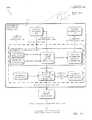
- FIG. 5depicts a simplified block diagram of at least one embodiment of a coding processor as disclosed herein;
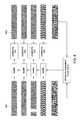
- FIG. 6depicts a simplified example of at least one embodiment of a multiresolution iris code as disclosed herein;
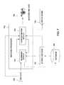
- FIG. 7depicts a simplified block diagram of at least one embodiment of a matching processor as disclosed herein;
- FIG. 8depicts a simplified example of at least one embodiment of a process for matching iris codes, which may be performed by the matching processor of FIG. 7 ;
- FIG. 9is a simplified schematic depiction of a coarse-fine algorithm to estimate flow-field of an iris code, as disclosed herein;
- FIG. 10is a simplified flow diagram depicting at least one embodiment of a method for estimating flow field between two iris codes, as disclosed herein;
- FIG. 11is a simplified flow diagram depicting at least one embodiment of a method for estimating flow field between two iris codes as disclosed herein;
- FIG. 12depicts a simplified schematic diagram of at least one embodiment of a computer system for implementing the iris processor of FIG. 1 , as disclosed herein;
- FIG. 13is a simplified assembled perspective view of at least one embodiment of an iris biometric recognition module
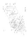
- FIG. 14is an exploded perspective view of the iris biometric recognition module of FIG. 16 ;
- FIG. 15is a simplified schematic diagram showing components of an iris biometric recognition module and an access control module in an environment of the access control assembly of FIG. 13 ;
- FIG. 16is a simplified flow diagram of at least one embodiment of a method for performing iris biometric recognition-enabled access control as disclosed herein, which may be performed by one or more components of the iris biometric recognition module of FIG. 13 ;
- FIG. 17is a simplified block diagram of at least one embodiment of a system including an iris biometric recognition module as disclosed herein;
- FIG. 18is a simplified view of at least one embodiment of an iris biometric recognition enabled access control assembly in an exemplary operating environment (i.e., a mobile device);
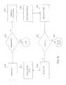
- FIG. 19is a flowchart depicting an exemplary method for activating wireless capability of a device.
- FIGS. 1-12relate to subject matter that is shown and described in U.S. Utility patent application Ser. No. 14/100,615, filed Dec. 9, 2013, and U.S. Utility application Ser. Nos. 14/509,356 and 14/509,366, both filed Oct. 8, 2014.
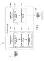
- FIG. 1depicts a block diagram of an iris processor 100 for biometric iris matching in accordance with exemplary embodiments of the present invention.
- the iris processor 100comprises a pre-processor 102 , a coding processor 104 and a matching processor 106 .
- the iris processor 100receives images as input, for example, input image 101 and outputs a matched iris 108 from a remote or local database.
- the databasemay be accessed as a “cloud” service, directly through an internet connection, or the like.
- the pre-processor 102 , the coding processor 104 and the matching processor 106may execute on a single device (e.g., within a software application running on, for example, a mobile device, having captured the images via a camera and/or means of illumination integrated into the mobile device), or on different devices, servers, cloud services or the like, as indicated by the dashed outline of the iris processor 100 .
- the iris processor 100may be modular and each processor may be implemented, e.g., on a single device, multiple devices, in the cloud as a service. Any of the components, e.g., the pre-processor 102 , the coding processor 104 , and the matching processor 106 , may be implemented or used independently of one another.
- the input image 101is an infrared image, and is captured by an infrared capture device (not shown in FIG. 1 ), coupled to the iris processor 100 .
- the infrared capture devicemay be any type of infrared capture device known to those of ordinary skill in the art.
- the input image 101is a red, green, blue (RGB) image, or the like.
- the input image 101contains an eye with an at least partially visible iris and pupil and the iris processor 100 attempts to match that eye with an iris of an eye image in a local or remote database of eye images.
- irisesare matched based on Hamming distances between two coded iris images.
- the input image 101is processed by the pre-processor 102 .
- the pre-processor 102segments and normalizes the iris in the input image 101 , where input image 101 may have variable iris/pupil and iris/sclera contrast, small eyelid openings, and non-frontal iris presentations.
- the result of the pre-processor 102is a modified iris image with clearly delineated iris boundaries and synthesized quasi-frontal presentation. For example, if the iris in the input image 101 is rotated towards the left, right, up or down, the pre-processor 102 will synthesize an iris on the input image 101 as if it was positioned directly frontally. Similarly, a frontally positioned pupil will be synthesized on the skewed or rotated pupil of the input image 101 .
- the coding processor 104analyzes and encodes iris information from the iris image generated by the pre-processor 102 at a range of spatial scales so that structural iris information contained in the input image 101 of varying resolution, quality, and state of focus can be robustly represented.
- the information content of the resulting codewill vary depending on the characteristics of input image 101 .
- the code generated by the coding processor 104 representing the input image 101allows spatial interpolation to facilitate iris code alignment by the matching processor 106 .
- the output code from the coding processor 104is coupled to the matching processor 106 .
- the matching processor 106incorporates constrained active alignment of iris structure information between stored iris images and captured iris codes generated from the input image 101 to compensate for limitations in iris image normalization by the pre-processor 102 .
- the matching processor 106performs alignment by performing local shifting or warping of the code to match the generated code with a stored iris code template based on estimated residual distortion of the code generated by the coding processor 104 . According to some embodiments, a “barrel shift” algorithm is employed to perform the alignment. Accordingly, structural correspondences are registered and the matching processor 106 compares the aligned codes to determine whether a match exists. If a match is found, the matching processor returns matched iris data 108 .
- the matched iris data 108may be used in many instances, for example, to authenticate a user in order for the user to gain access to a secure item (e.g., a safe, safety deposit box, computer, etc.), authenticate a user to access applications or wireless communication within a computing device, such as a mobile device (e.g., authenticating a user in order to transmit instructions from the user's mobile device to an automated teller machine (ATM) in order to complete a financial transaction), authorize financial transactions and/or collect, analyze and display an identify of a user in order to deliver targeted marketing to the user, as described in detail below.
- a secure iteme.g., a safe, safety deposit box, computer, etc.
- ATMautomated teller machine
- the pre-processor 102may be an application executing on a mobile device, such as a mobile phone, camera, tablet, forward or rear facing camera integrated into a mobile phone or table, or the like.
- the pre-processor 102 on the mobile devicemay capture an image of a user's eye using the camera of the device, perform the pre-processing steps on the mobile device, and then transmit a bundled and encrypted request to the coding processor 104 , which may be accessed via a cloud service on a remote server of, for example, a transaction initiated and completed via a wireless communication from a mobile device to an ATM and/or remote server in order to complete a financial transaction with a financial institution.
- the application on the mobile devicemay also comprise the coding processor 104 and the iris coding is performed on the mobile device.
- the iris processor 100may be used to authorize a cellular device user, determining whether the device is stolen or not, in conjunction with geo-location data, or the like.
- the usermay “imprint” their identity on the device based on their iris information so that others can be prevented from using the device if reported stolen.
- this imprintmay be used to authenticate the mobile device user to access user-specific applications and or settings on the mobile device, including those that utilize wireless communication transmissions.
- Authorizationcan also be extended to the office or personal environments, where the iris processor 100 may be used to determine whether an authorized or detected user has access to a particular location or security enabled object within that particular location.
- taking photographsmay be prohibited for the majority of employees, but overriding this prohibition and enabling the camera is available to authorized employees.
- the employee's mobile devicewill be used to capture an image of the employee, and the iris processor 100 will match the iris of the employee to extract an employee profile, which delineates the authorizations for this employee.
- the iris processor 100may be used to determine whether a person accessing particular medical resources, such as medicine, devices, or the like, are permitted to access these resources.
- the iris processor 100can be coupled with a recording device, which captures video of those accessing a medicine cabinet, for example, and whether they are authorized to take medical resources from the cabinet.
- the iris processormay be used in any context in which the user needs to be authenticated, including any situation in which the user wants physical or electronic access to a device or data accessible via the device.
- FIG. 2depicts a block diagram of the pre-processor of the iris processor 100 in accordance with exemplary embodiments of the present invention.
- the pre-processorreceives the input image 101 and outputs a rectified iris image 220 .
- the rectified iris image 220corrects for uncontrolled capture scenarios such as ambient illumination conditions, varied illumination geometries, reduced eyelid opening area, presentation angle (obliquity), or the like.
- the rectified iris image 220corrects for various nonconformities.
- the pre-processor 200comprises a segmentation module 202 and a correction module 204 .
- the segmentation module 202further comprises a pupil segmentation module 206 , an iris segmentation module 208 and an edge detection module 209 .
- the segmentation module 202corrects an input image for low-contrast pupil and iris boundaries.
- the image produced by the segmentation module 202is then coupled to the correction module 204 for further correction.
- the correction module 204comprises a tilt correction module 210 and a corneal correction module 212 . The details of the segmentation module 202 are described below.
- FIG. 3Aillustrates that varying illumination geometry produces varying pupil appearance.
- FIG. 3Aillustrates measurement of pupil-iris intensity difference as a function of distance, e.g., 1 and 2 meters, pupil size, e.g., 2.4 mm and 4.0 mm, and camera/illuminator distance, e.g., 6 to 16 cm. As the camera/illuminator distance increases, the pupil iris intensity decreases. The contrast of the pupil varies greatly as a function of distance between camera and subject as well as functions of illuminator geometry and pupil diameter. The variation with distance is due to the fact that the angular distance between the illuminator and camera axes are greater at short range (e.g., 1 m) than at longer distances.
- the segmentation module 202 and the correction module 204may be used, for example, in the medical field, in targeted marketing, customer tracking in a store, or the like.
- pupil and iris insertionmay be performed by the pre-processor 102 , as described further with respect to FIGS. 2 and 3A-3D , in the medical field as a diagnostic tool for diagnosing diseases that a person might have based on their iris profiles.
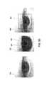
- FIG. 3Billustrates an example of iris and pupil boundary matching in accordance with exemplary embodiments of the present invention.
- iris diametersare normalized by the iris segmentation module 208 . Size normalization is performed using a range estimate derived from an autofocus setting of the camera taking the image.
- the image 300shows the pupil boundary 304 calculated by the pupil segmentation module 206 .
- the pupil segmentation module 206then inserts an artificial dark pupil in the pupil boundary 304 in image 300 .
- Image 300is then coupled to the iris segmentation module 208 , which calculates the iris boundary.
- FIGS. 3C and 3Dillustrate examples of inserted artificial pupils and iris boundaries.
- input image 320is coupled to the pre-processor 200 .
- the input image 320is then segmented by pupil segmentation module 206 to calculate a pupil boundary region 326 .
- the pupil segmentation modulethen inserts an artificial black colored pupil in the pupil boundary region 326 .
- oblique irises and pupilsare warped to be circular.
- the insertion of an artificial pupil in the pupil boundary region 326may be used, for example, to remove red-eye effects in an image captured by a camera.
- the segmentation module 202can be used to segment the pupil and iris areas, and the pupils may be red-eye corrected by insertion of the artificial pupil. This process of segmentation and warping is described in more detail below.
- FIG. 3Dshows a similar process but on a downward facing iris in image 350 .
- the pupil boundary 356is still detected despite being occluded by the eyelid in image 352 .
- the pupil and irisare both warped to form circular regions to aid in segmentation.
- the pupil segmentation module 206inserts a black disk/artificial pupil in the image 352 and couples the image 352 to the iris segmentation module 208 .
- the iris segmentation module 208determines an iris boundary 358 .
- the iris and pupil boundariesare corrected for various lighting conditions and presented in image 354 , where region 360 can be seen with the artificial pupil.
- the artificial pupilneed not be necessarily black and may be another suitable color, based on compatibility with third party iris recognition software.
- the pupil boundariesfor example, 304 , 326 and 356 and the iris boundaries (iris/sclera boundary areas), for example, 306 , 328 and 358 are calculated using a Hough transform, according to one embodiment.
- the pupil segmentation module 206 and the iris segmentation module 208employ edge detection using the edge detection module 209 to generate edge maps which works for varying scales of grayscale pupils, even in instances with low edge contrast.
- the pupil segmentation module 206determines the segmented pupil area (and therefore, the pupil contour) and the pupil and iris have been warped to form circular regions, the segmented pupil area is replaced with a black or dark disk to simulate the appearance of a dark pupil.
- FIG. 4Adepicts a flow diagram for a method 400 for edge detection in accordance with one embodiment of the present invention.
- the method 400is an exemplary illustration of the operation of the edge detection module 209 used to detect pupil and iris boundaries.
- an edge mapis generated from an image of an eye, for example, input image 101 .
- An exemplary edge map for an iris image which was brightly illuminatedis shown in FIG. 48 , image 420 .
- Image 422is an edge map for an iris image which was not as brightly illuminated, i.e., an indistinct pupil whose edges are not as clearly visible as those in image 420 .
- step 406candidate pupil contours are constructed for the given edge map.
- Step 406consists of sub-steps 406 A and 4068 .
- a first candidate pupil contouris created from a best fitting circle, as shown in FIG. 48 , image 420 .
- a Hough transform or RANSAC (random sample consensus) methodcan be used to find the circle that has the greatest level of support in the edge map in the sense that the largest fraction of circle points for that circle coincide with edge points.
- a second candidate pupil contouris constructed from a best inscribed circle as shown in FIG. 48 , image 422 .
- an inscribed circleis a circle that can be drawn in an area/region of the edge map so that no edge points (or no more than a specified small number of edge points) lie within the circle.
- the best inscribed circleis the largest such inscribed circle that can be found in the area/region of the pupil. Then method then proceeds to step 408 , where the method 400 determines the best matching candidate pupil contour from the first and second candidate pupil matching contours for the edge map.
- the best matchis determined by assessing a level of support for the best fitting circle and selecting the best fitting circle as the best match if this level of support is above a threshold value. The best inscribed circle is selected as the best match if the level of support for the best fitting circle is below a threshold value.
- an automatic process based on how well the best fit contour (circle) matches the edge contour in the edge contour mapis used to decide which candidate contour to choose. For example, for the best supported circle described above, a subset of edge points can be selected that is limited to those edge points whose angular orientation is consistent with that edge point being a part of the candidate circle. In other words only edge points whose direction is approximately perpendicular to the direction from the estimated center of the candidate circle are included. This process eliminates from consideration those edge points that may accidentally fall at the correct position to be part of the circle but that do not correspond to the actual circle contour. If the proportion of such selected edge points is greater than some specified fraction (e.g.
- the level of support for that circleis deemed to be sufficient and the best fitting circle is selected. If the level of support by the selected edge points is less than this threshold then the best fitting circle is deemed to have insufficient support and the best inscribed circle is selected instead.
- the best fit candidate contourwill provide accurate pupil segmentation in the bright pupil image, as shown in FIG. 48 , image 420 , where the bright colored eye edge map is overlayed with the best-inscribed circle 430 and the best fitting circle 432 . The method then terminates at step 412 when a best matching candidate pupil contour is found.
- iris imagesmay be captured over a range of oblique viewing conditions, for example, where gaze deviation with nasal gaze angles ranges from 0 to 40 degrees, as shown in FIG. 3D .
- the tilt correction module 210rectifies the images for this tilt and generates a tilt corrected image.
- a tilt-corrected imagemay be generated by estimating or determining the magnitude and direction/angle of tilt, and then applying a geometric transformation to the iris image to compensate for the oblique viewing angle.
- the simplest form of this transformationis a stretching of the image in the direction of the tilt to compensate for the foreshortening caused by the angle between the iris and the image plane.
- Such a non-isotropic stretchingis mathematically represented as an affine transformation.
- a more accurate version of this geometric de-tiltingreplaces the affine transformation with a projective transformation which better represents the image representation of a pattern on a flat, tilted surface.
- the correction module 204has several uses independent of the other components of the iris processor 100 .
- the correction module 204may be used to detect a person's gaze, or to track a person's gaze continuously by capturing one or more frames of a person's eyes.
- the tilt correction module 210may, for example, be used to continuously track a user's gaze on a mobile device and scroll a document, perform a swipe or the like. This tilt detection can be used, for example, independently of the matching processor 106 described in FIG. 1 to enable or disable the display of a mobile device.
- the correction module 204corrects the input image 101 prior to the segmentation module establishing artificial pupil discs on the input image 101 .
- tilt correctionmay still show distortions such as the apparent eccentric pupil compression of the nasal portion of the iris, causing difficulty in biometrically matching the iris with a stored iris image.
- the distortionis caused by the optical effect of the cornea and anterior chamber of the human eye through which the iris is imaged. These two structures have similar refractive indexes (1.336 for the aqueous humor that fills the anterior chamber and 1.376 for the cornea) so that together their optical effect is approximately that of a single water-filled plano-convex lens in contact with the iris.
- the tilt corrected image generated by the tilt correction module 210is coupled to the corneal correction module 212 , which corrects for the above described corneal distortion.
- FIG. 4Cdepicts a flow diagram for a method 440 for corneal distortion correction in accordance with exemplary embodiments of the present invention.
- the method 400is an exemplary illustration of the operation of the edge detection module 209 .
- the methodbegins at step 402 and proceeds to step 404 .
- the tilt correction module 210estimates the angle of tilt of the iris with respect to the camera orientation.
- the tiltcan be estimated roughly by finding the pupil center and measuring the distance between that center and the bright reflection in the cornea caused by the near infra-red illuminator used in iris imaging.
- Other methods of tilt estimation known to those of ordinary skill in the artmay also be used. Indeed, any method of tilt estimation may be substituted herein.
- step 406the image is corrected for the perspective distortion, i.e., the foreshortening of the iris that occurs.
- the effect of foreshorteningcan be approximated as a simple compression of the captured image in the direction or tilt. This effect can therefore be compensated for by simply stretching the image in the direction derived from the tilt estimation step.
- a more accurate correctioncan also be performed by using a projective transformation to more precisely capture the foreshortening effect.
- the method 400corrects for effects of optical distortion due to viewing through the tilted cornea.
- approximate correction for the optical distortion discussed abovecan be achieved by measuring and correcting the effects of pupil eccentricity and pupil elongation.
- the methodterminates at step 450 .
- the pupilstill appears shifted to the left with respect to the center of the iris and the pupil appears elongated in the horizontal direction.
- the corneal correction module 212corrects for these distortions without modeling the optical elements that produced them by non-linearly warping the iris area/region to force the iris contour 466 and pupil contour 468 to become concentric circles.
- the corneal correction module 212creates this nonlinear warping function by defining a set of spokes 470 that connect points on the non-circular pupil contour 468 to corresponding points on the non-circular iris/sclera contour 466 and mapping each spoke of the spokes 470 to a position connecting a synthetic circular pupil contour 472 to a concentric circular iris/sclera contour 474 .
- the described transformationis then applied to the underlying image 460 .
- the result of this mapping(with appropriate interpolation) is shown in image 476 . After the pupil and iris areas/regions have been shifted to be in concentric circles, the coding process can be more accurately performed with better matching results.
- iris coding and matchingcan be performed using any desired iris biometric algorithm designed to be applied to iris images captured under standard controlled conditions.
- any desired iris biometric algorithmdesigned to be applied to iris images captured under standard controlled conditions.
- DaugmanDigits, J., “High confidence visual recognition of persons by a test of statistical independence”, IEEE Transactions on Pattern Analysis and Machine Intelligence, 15 (11), pp 1148-1161 (1993)
- methods developed by otherscan also be used, including but not limited to those of Munro (D. M. Monro and D. Zhang, An Effective Human Iris Code with Low Complexity, Proc. IEEE International Conference on Image Processing, vol. 3, pp. 277-280, September 2005) and Tan (Tan et al, Efficient Iris Recognition by Characterizing Key Local Variations IEEE TRANSACTIONS ON IMAGE PROCESSING, VOL. 13, NO. 6, June 2004).
- FIG. 5depicts a block diagram of a coding processor 500 in accordance with exemplary embodiments of the present invention.
- the coding processor 500comprises a coordinate module 502 and an extraction module 506 .
- the coordinate module 502constructs an invariant coordinate system for an invariant coordinate system image representation that allows iris information extracted from varying iris images to be brought into register, so that corresponding spatial information can be compared.
- the extraction module 506extracts information from the iris image for supporting a strong rejection of the hypothesis that two eye images presented represent statistically independent patterns.
- the coding processor 500prepares the segmented and corrected iris image 220 for accurate matching with other iris images and allows unconstrained iris capture applications.
- image size and focusmay vary with distance, in addition to individual iris structure variations and variation with illumination wavelength of spatial information content of an iris structure.
- iris codingis based on angular frequencies between about 15 and 40 cycles/2pi or 2.5 and 6 pixels per cycle, where according to one embodiment, the present application achieves robust matching based on the codes generated by the coding processor 500 down to approximately 40 pixels per iris diameter.
- the coding processor 500uses a variant of Daugman's local phase representation, which encompasses a multi-resolution coding approach rather than choosing a single scale of analysis. Lower frequency components remain available in lower resolution images and are less prone to loss in defocused or otherwise degraded images.
- the variant of Daugman's local phase representationallows for dense coding that is useful when dealing with iris images in which significant occlusion may occur.
- Daugman type phase coding approachgenerates a code that represents all available parts of the iris images. This is in contrast to an approach that uses sparse local features that might be occluded or otherwise unavailable in a particular image to be matches. Further, the use of multiresolution phase approach preserves the possibility of achieving code-level compatibility with existing phase-based representations. In addition to containing multi-scale information, the code that is created can incorporate additional information to facilitate estimation of iris code alignment and spatial interpolation of local structure information prior to comparison.
- the coding processor 500comprises the coordinate module 502 .
- the coordinate module 502transforms the rectified iris image 220 into a polar iris image 504 .
- the pupil boundaryappears at the top (notice the specular reflection of a biometric scanner illuminator column) and the iris-sclera boundary area appears at the bottom.
- the angular dimensionruns clockwise from 3 o'clock at the left of the image. Proceeding from left to right, the lower and upper eyelids can be seen. Note that in image 504 the eyelashes extend from the upper eyelid all the way into the pupil.
- the image 504is coupled to the extraction module 506 that filters and subsamples the polar iris image 504 to produce a multi-resolution iris code representation 520 , an example of which is shown in FIG. 6 .
- the image 504is passed through a series of bandpass filters to produce a set of filtered images.
- FIG. 6shows an example of a polar iris image 620 , being filtered by filters 121 (Filters 1 . . . 5) and producing an iris code 622 comprising filtered bands 600 , 602 , 604 , 606 and 608 , respectively high-frequency domain bands to low frequency domain bands.
- the five bands showncorrespond to Gabor filter (a linear filter used for harmonic analysis, wavelet decompositions, and edge detection) carrier wavelengths of 6, 8, 12, 16, and 24 pixels with respect to a polar image sampled at 200 pixels around the iris. Therefore, the frequencies correspond approximately to angular spatial frequencies of 33, 25, 16, 12, and 8 cycles per 2pi.
- Gabor filtera linear filter used for harmonic analysis, wavelet decompositions, and edge detection
- the higher frequenciesare comparable to those used in standard iris matching algorithms.
- the mask 610is the union of two masks: a mask (common to all bands) based on analysis of the intensities in the input polar iris image 504 that masks off area corresponding to specular reflections and approximate location of eyelid and eyelash areas, and a mask based on the signal strength in the Gabor filtered image that masks off areas in which local phase measurement is unstable (unstable regions).
- Multi-resolution representation as shown in iris code 622allow representation of information from images at different camera-subject distances that result in iris images differing in number of pixels per unit distance at the iris as well as oblique camera views causing foreshortening and optical demagnification, as discussed above with reference to FIGS. 2-4D .
- an iris code representation 520includes a complete description of the filter characteristics, spatial sampling, representation and quantization.
- Filter characteristicscomprise one or more of center frequencies, bandwidths, functional type (e.g. log Gabor), and orientation tuning
- Spatial samplingcomprises one or more of spacing along the radial and angular normalized image axes for each filter type, and quantization specifies the number levels with which each value is represented or number of bits assigned to each.
- the iris code representation 520 and exemplary iris code 622is a warpable code allowing for interpolation by using sub-Nyquist spatial sampling requirements for each filter 1 . . . 5 in filters 621 that produces provide a criterion for sufficient sampling for accurate interpolation.
- the sub-Nyquist spatial samplingis combined with a finer intensity quantization than the 1 bit per complex phase component used in Daugman-type coding. For example, if 4 bits are used for each complex phase component this corresponds to roughly 64 steps in phase angle and thus a maximum interpolation error of pi/32 radians or less than six degrees.
- non-quantized iris codesmay also be matched, where original complex band-pass filter outputs are stored without quantization.
- the filter outputsare normalized in magnitude so that each represents a complex number on the unit circle.
- Data masksare generated based on occlusions and local complex amplitude.
- the match measure that is the closest analog of the standard Hamming Distance measure of a Daugman iris codeis based on a phase difference histogram. This histogram constructed by computing the angles between the phase vectors of the two codes being compared (see FIG. 6 ), and compiling a histogram (subject to the valid data mask) of phase differences between ⁇ pi and pi. These phase differences should be small if the codes represent the same eye and more or less uniformly distributed if the codes represent statistically independent eyes.
- FIG. 7An example of two such histograms is shown in FIG. 7 .
- the histogram on the leftcorresponds to an impostor match and the one on the right to an authentic match.
- the authentic distributionis tightly concentrated around a zero phase shift with only a small proportion of the phase difference values larger than pi/2 in absolute value.
- the impostor histogramshows many large phase differences and no clear evidence of concentration around zero value.
- the fraction of values larger than pi/2can be used to generate a match statistic that behaves very much like Daugman code Hamming distance if this is desired.
- there are many other measures of central concentration and dispersionthat may be used to distinguish between authentic and impostor distributions, as will be described below.
- give sufficient training sets of impostor and authentic histogramsit may be beneficial to use statistical classification or machine learning techniques such as discriminant analysis, Support Vector Machines, Neural Networks, or Logistic Regression to construct an optimal decision procedure for some class of data.
- datais analyzed over a periodic domain by employing a Fourier series expansion to compute circular harmonics.
- the relative magnitude low order circular harmonicsgive information about degree of concentration of the data. Transformation of the histogram data using circular harmonics is beneficial prior to use of learning techniques to construct a decision procedure.
- phase difference histogramaids in analysis of the match level between two codes but does not represent all of the information relevant to the comparison of two codes. If the phase difference value varies as a function of the absolute phase then the histogram shows low concentration (i.e. large dispersion) even given a strong relationship.
- a Mutual Information or other conditional entropy descriptionis employed to prevent this problem, which measures the reduction in the entropy of one random variable given knowledge of the value of another random variable. This more complete characterization can detect relatedness even where the variables are uncorrelated.
- phase difference histogramAnother limitation of the phase difference histogram is that it completely suppresses spatial information since the histogram is a global statistic. However, local or patchwise uniformity of phase differences or other detectable relatedness would also be sufficient to conclude that the codes are not independent. This local analysis could be achieved using local histogram analysis, mutual information, or spatial correlation analyses.
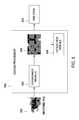
- FIG. 7depicts a block diagram of a matching processor 700 in accordance with exemplary embodiments of the present invention.
- the matching processor 106comprises an alignment module 702 and a flow estimation module 704 .
- the iris code 520 generated by the coding processor 500 as shown in FIG. 5is coupled to the alignment module 702 .
- the alignment module 702performs various alignments to the iris code 520 based on matching algorithms described below.
- the alignment module 702further couples the iris code 520 to the flow estimation module 704 to generate estimated flow vectors to aid in matching.
- the alignment module 702compares the iris code 520 to an iris code 706 from database 708 to determine whether a match exists.
- a matchdoes not exist, more iris codes from the database 708 are compared with the iris code 520 . Match scores are determined, and if the match score meets or is below a predetermined threshold, then a match exists. According to exemplary embodiments, a Hamming distance is used as a match score. Ultimately, the matched iris data 108 is returned by the matching processor 700 . According to some other embodiments, flow estimation is applied to information derived from the unknown iris code 520 and the stored iris code 706 . This information may be part of the iris code 520 per se or it may not. The resulting flow field from the flow estimation module 704 is used to generate a modified iris code that is matched against a reference iris code by the matching processor 700 to produce a match score 720 .
- a Hamming distancerepresents a binary distance based on XOR operations to computes the number of bits that differ between two binary images.
- the alignment module 702performs a Daugman barrel shift on the iris codes, i.e., finds the iris code rotation that provides the best match between the iris codes being compared.
- the matching algorithm employed by the matching processor 700is a modified algorithm using the Hamming distance (HD) for each set of barrel shift positions and taking the lowest Hamming distance as the score for that pair of codes.
- the unknown codeis deemed to be a match. If the HD is above the threshold then the unknown code is labeled an impostor. In one embodiment, the threshold depends on details of the iris code structure and on the statistical requirements of the matching scenario.
- the modified algorithm employed by the alignment module 702 barrelshifts the iris codes being compared and also locally aligns the iris codes to each other to compensate for inaccuracies in iris image normalization due to uncorrected optical distortion or complexities of iris dilation and contraction.
- the local alignment functionperformed by alignment module 702 , allows compensation for distortions in the input iris image that are not uniform across the iris. This is accomplished by shifting local regions of the code to bring them into more accurate alignment with corresponding regions of the reference code.
- this processis performed using very small estimation regions, virtually any iris code can be made to match any other iris code, which can result in false matches being generated.
- This false matching problemcan be avoided by imposing suitable smoothness conditions on the estimated flow field. For example, if the flow field is estimated by performing local translation estimation using relatively large estimation regions then the local flow estimates will represent the average motion over this relatively large region.
- the alignment module 702further produces multiple match scores for each comparison, between iris code 520 and 706 for example, because each iris code contains multiple frequency bands.
- FIG. 8depicts the process of matching iris codes performed by the matching processor 700 in accordance with exemplary embodiments of the present invention.
- the first code 800 and the second code 802 to be matchedare represented as values over the rectified (e.g., polarized) iris image coordinate system consisting of an angular and a normalized radial coordinate.
- a local displacement function or flow fieldis computed by the flow estimation module 704 of the matching apparatus in FIG. 7 and coupled to the alignment module 702 that best aligns structure in the first iris code 800 to corresponding structure in the second code 802 , subject to some smoothness or parametric constraint.
- This flow field estimationcan include the effect of standard barrel shift alignment or that can be performed as a separate step.
- the vectors in this flow fieldeach specify the displacement in the normalized image coordinate system at which the image structure in the first code 800 best matches the structure in the second code 802 .
- Each band in first iris code 800is transformed using this displacement function to produce an aligned iris code, and the Hamming distance between this aligned iris code and the corresponding band of the second code 802 is computed. Because the transformation is constrained to be smooth, impostor codes will not be transformed into authentic codes as will be described below.
- the flow estimation module 704computes a flow field at a reduced resolution for each iris code, and smoothly interpolates the flow field to produce a final estimate.
- the flow estimation module 704employs a pyramid-based coarse-fine flow estimation technique, though those of ordinary skill would recognize that other techniques may be used instead.
- the alignment module 702introduces a small local shift in one band of each of the first iris code 800 and the second iris code 802 , the shift being in the angular direction and equal at all radial positions. The displacement shift also varies smoothly in the angular direction.
- a coarse-fine algorithmis used by the flow estimate module 704 to estimate the flow field between codes 800 and 802 from the low resolution bands of the codes.
- the alignment module 702then warps the code 800 by the estimated flow field resulting in a significantly decreased Hamming Distance, signaling a high confidence match.
- a Hamming distance ⁇ 0.3indicates a high confidence match.
- Various matchesmay correspond with different Hamming distance values qualifying as high confidence matches.
- the matching processor 700may match two iris codes by employing a mutual information measure based on the phase angles of the codes being compared as well as measures based on the local difference of phase angles.
- FIG. 9is a depiction of the coarse-fine algorithm described above to estimate flow-field of an iris code in accordance with exemplary embodiments of the present invention.
- Coarse-fine refinementoperates on a “pyramid” structure that is essentially a collection of bandpass filtered version 904 - 1 to 904 -N and 906 - 1 to 906 - 1 of the input images 900 and 902 respectively, as shown in FIG. 9 .
- the displacements 908 - 1 to 908 -N estimated at the previous levelare used to warp the current level image and then an incremental displacement is computed based on the residual difference between the warped level and the corresponding pyramid level in the other image. This process continues until the highest level is reached and the result is the final estimated flow field 910 .
- the multi-resolution iris codeis itself a collection of bandpass filtered versions of the images with which alignment is desired, according to one embodiment, these bands themselves could be used to drive the alignment process in the alignment module 702 . This would produce a truly “self aligning” iris code. In this approach there is no need to store additional alignment data as part of the multi-resolution iris code structure.
- FIG. 10is a flow diagram depicting method 1000 for estimating flow field between two iris codes in accordance with exemplary embodiments of the present invention.
- the methodis an implementation of the flow estimation module 704 .
- the methodbegins at step 1002 and proceeds to step 1004 .
- the flow estimation module 704generates a first plurality of images from a first input image (i.e., a first iris code) and a second plurality of images from a second input image (i.e., a second iris code to be matched against) using a bandpass filter, the first and second plurality of images comprising images ranging from low frequency to high frequency bands.
- step 1006the flow estimation module 704 selects an image from the first plurality of images in the lowest frequency band that has not been processed, i.e., for which there is no previous flow-field estimate.
- step 1008the flow estimation module 704 determines whether a flow field has been estimated in a lower frequency band between the first and second plurality of images. If a flow field has been estimated in a lower frequency band, the method proceeds to step 1010 , where the selected image is warped using the lower frequency band flow field estimate.
- step 1012a flow field is estimated by the flow estimation module 704 on the residual difference between the warped image and a second image at the same frequency band from the second plurality of images.
- step 1014the flow estimation module 704 determines whether all frequency bands have been processed. If not, then the method returns to step 1006 to process the next higher frequency band until all frequency bands have been processed. When all frequency bands have been processed (i.e., warped by lower frequency flow field estimates), the method proceeds to step 1016 , where the final flow field estimate is returned to the matching processor 700 . The method terminates at step 1018 .
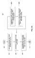
- FIG. 11is a flow diagram depicting method 1100 for estimating flow field between two iris codes in accordance with exemplary embodiments of the present invention.
- the methodis an implementation of the iris processor 100 .
- the methodbegins at step 1102 and proceeds to step 1104 .
- the pre-processor 102pre-processes and input image containing an eye to produce a rectified iris image with rectified pupil and iris boundaries, and correction for tilt and corneal distortion.
- the methodproceeds to step 1106 , where the coding processor 104 codes the rectified iris image into a multiresolution iris code.
- the iris codecontains multiple frequency band representations of a polarized version of the rectified iris image.
- the methodthen proceeds to step 1108 , where the multiresolution iris code is compared to a set of stored iris codes in a database to determine whether the iris code is contained in the database and returns data associated with the matched iris.
- the methodterminates at step 1110 .
- FIG. 12depicts a computer system for implementing the iris processor 100 in accordance with exemplary embodiments of the present invention.
- the computer system 1200includes a processor 1202 , various support circuits 1205 , and memory 1204 .
- the computer system 1200may include one or more microprocessors known in the art similar to processor 1202 .
- the support circuits 1205 for the processor 1202include conventional cache, power supplies, clock circuits, data registers, I/O interface 1207 , and the like.
- the I/O interface 1207may be directly coupled to the memory 1204 or coupled through the support circuits 1205 .
- the I/O interface 1207may also be configured for communication with input devices and/or output devices such as network devices, various storage devices, mouse, keyboard, display, video and audio sensors, visible and infrared cameras and the like.
- I/O interfaces 1207such as an integrated camera (possibly used in association with an on-board standard and/or infrared illumination device) or a wireless communication device (e.g., CNFC, RFID, Bluetooth, Wi-Fi, Wimax, Satcom, etc.), may be directly coupled to the memory 1204 and/or coupled through the support circuits 1205 .
- one or more software applications or appsmay be configured to access the camera, illuminator and/or wireless communication device to accomplish the embodiments disclosed herein.
- the appsmay receive data (e.g., iris data) via the I/O interface 1207 and transmit the data, possibly via the support circuits 1205 to the memory 1204 running the app (e.g., Iris Processor 100 or Iris Biometric Recognition Module 1514 ).
- the appmay perform any of the algorithms disclosed herein, and transmit the results (possibly via memory 1204 and/or support circuits 1205 ) to the I/O interfaces 1207 (e.g. via wireless communication) to a server and/or an additional wireless communication device (e.g., an ATM or security-enabled device such as a safe), to authenticate a user of the device.
- a server and/or an additional wireless communication devicee.g., an ATM or security-enabled device such as a safe
- the memory 1204stores non-transient processor-executable instructions and/or data that may be executed by and/or used by the processor 1202 . These processor-executable instructions may comprise firmware, software, mobile apps, and the like, or some combination thereof. Modules having processor-executable instructions that are stored in the memory 1204 comprise an iris processor 1206 .
- the iris processor 1206further comprises a pre-processing module 1208 , a coding module 1210 and a matching module 1212 .
- the memory 1204may further comprise a database 1214 , though the database 1214 need not be in the same physical memory 1204 as the iris processor 1206 .
- the database 1214may be remotely accessed by the iris processor 1206 via a cloud service.
- the iris processor 1206may also have several components that may not be co-located on memory 1204 .
- the pre-processing module 1208is local to the computer system 1200 or mobile device, while the coding module 1210 and the matching module 1212 may be accessed as cloud services via a wired or wireless network. In other instances, only the matching module 1212 is accessed via a network. Communication between each module may be encrypted as the data travels over the network.
- the computer system 1200may be programmed with one or more operating systems 1220 (generally referred to as operating system (OS)), that may include OS/2, Java Virtual Machine, Linux, SOLARIS, UNIX, HPUX, AIX, WINDOWS, WINDOWS95, WINDOWS98, WINDOWS NT, AND WINDOWS2000, WINDOWS ME, WINDOWS XP, WINDOWS SERVER, WINDOWS 8, Mac OS X, IOS, ANDROID among other known platforms.
- OSoperating system
- OSoperating system
- the memory 1204may include one or more of the following random access memory, read only memory, magneto-resistive read/write memory, optical read/write memory, cache memory, magnetic read/write memory, and the like, as well as signal-bearing media as described below.
- the computer system 1200may be a mobile device such as a cellular phone or tablet device, for example.
- the mobile devicemay contain a camera and have the iris processor 1206 stored on memory as an application.
- the iris processor 1206may be a part of the operating system 1220 .
- the iris processor 1206may be an independent processor, or stored on a different chip than the processor 1202 .
- often mobile deviceshave camera processing modules and the iris processor 1206 , or portions of the iris processor 1206 , may reside on the camera processing module, where the imager in the camera is a CCD or CMOS imager.
- the mobile devicemay be customized to include some sensors, the type of the camera imager, or the like.
- An image sensormay include a camera or infrared sensor or illuminator that is able to project images or other objects in the vicinity of the device. It should be understood that image capture can be performed using a single image, multiple images, periodic imaging, continuous image capturing, image streaming, etc. Further, a device can include the ability to start and/or stop image capture, such as when receiving a command from a user, application, or other device.
- the computing devicecan include one or more communication elements or networking sub-systems, such as a Wi-Fi, Bluetooth, radio frequency (RF), wired, or wireless communication system.
- the devicein many embodiments can communicate with a network, such as the Internet, and may be able to communicate with other such devices.
- the devicecan include at least one additional input element able to receive conventional input from a user.
- This conventional inputcan include, for example, a push button, touch pad, touchscreen, wheel, joystick, keyboard, mouse, keypad, or any other such component or element whereby a user can input a command to the device.
- a devicemight not include any buttons at all, and might be controlled only through a combination of visual and audio commands, such that a user can control the device without having to be in contact with the device.
- the iris biometric recognition module 1514when assembled, is a self-contained unitary module. As such, the iris biometric recognition module 1514 can be incorporated into, for example, a security or locking features, for example a door lock assembly, or any other type of device, apparatus, article, or system that can benefit from an application of iris biometric recognition technology, including, for example, a mobile device, a mobile device compatible with wireless communication, an electronic device used in a financial transaction and/or an electronic advertisement display device.
- a security or locking featuresfor example a door lock assembly
- any other type of device, apparatus, article, or systemthat can benefit from an application of iris biometric recognition technology, including, for example, a mobile device, a mobile device compatible with wireless communication, an electronic device used in a financial transaction and/or an electronic advertisement display device.
- the biometric recognition module 1514may be integrated into, mounted on and/or otherwise coupled to an electronic item or device, for example, a computer or a mobile device (e.g., a laptop, a mobile telephone, a tablet, a watch or other accessory storing and/or displaying information or data or any other mobile device), in order to confirm that the user controlling the computer or mobile device is a user authorized to operate the device and any of the apps running on the device.
- a computer or a mobile devicee.g., a laptop, a mobile telephone, a tablet, a watch or other accessory storing and/or displaying information or data or any other mobile device
- an Iris Processor 100 and/or Iris Biometric Recognition Module 1514within the device, for example, a mobile device, allows the mobile device to match the received iris biometric information to a template stored in a database, thereby allowing the mobile device or any associated hardware or software, at a certain time, to identify and/or authenticate the user and/or create a biometric record that the user was authorized to access the mobile device at a specific time.
- the iris biometric recognition module 1514may be incorporated into an electronic item or device in order to authenticate the user to allow access to the wireless communication capabilities of the wireless device (NFC, Bluetooth, RFID, WiFi, WiMax, Satcom, etc), in order to communicate with another wireless communication capable devices to exchange information that would allow an event, task, or transaction to be completed.
- the wireless communication capabilities of the wireless deviceNFC, Bluetooth, RFID, WiFi, WiMax, Satcom, etc
- the wireless communication device contained in a mobile devicemay be authorized for use by the operator of the device, after iris biometric authentication, to activate an application that directs the wireless communication device to complete a defined event, task, or transaction (authorize a payment, open a door, gain access to information, etc.).
- applications that leverage the wireless communication devicemay be activated for a limited time period to allow the user to complete an event, task, or transaction associated with using the wireless communication device.
- the accurate biometric identification used to authenticate the usermay further provide access to any utilized wireless capabilities integrated into the mobile device. For example, if a user desired to use the mobile device to transmit a wireless communication to a second device (e.g., another mobile device, an ATM machine, or any other electronic device necessitating authentication) enabled for wireless communication, the user would authenticate themselves via iris biometric authentication, and once authenticated, would be enabled to transmit a wireless communication to the second device. Although additional biometrics may be used, the iris biometric method of authentication may be superior to other currently utilized methods of authentication, including PINS, swipes, and other biometrics.
- a second devicee.g., another mobile device, an ATM machine, or any other electronic device necessitating authentication
- the iris biometric method of authenticationmay be superior to other currently utilized methods of authentication, including PINS, swipes, and other biometrics.
- the userwants to unlock a door with a NFC device as the receiver, the user would authenticate his identify on his mobile device, which would enable an application on the mobile device that can be used to transmit a unique code from the NFC device on his mobile device to the door lock device to unlock the door.
- the NFCmay be locked and, if the user wants to perform another action that requires the NFC, he would be required to again authenticate his identity to enable the applications associated with the NFC.
- the door lock device or other lock devicemay be on a cabinet, safe, box, medical equipment container, residence, office, blood supply container, liquor cabinet, gun cabinet, jewelry box, locker, vehicle, or any other device, container, or object to be secured.
- the integration of the biometric recognition module 1514 in, for example, a computer, mobile device, or any other electronic devicemay be applied to a financial transaction originating from a software application.
- the biometric authentication of the user to operate, for example, a mobile devicemay occur using iris biometric recognition, as described above (rather than entering a PIN or password, as is typical of authenticating financial transactions), and the software application used to request the financial transaction may be accessed.
- the ability to complete the financial transactionmay be activated for a limited time period to allow the user to complete an event, task, or transaction.
- the software application and/or electronic devicemay be locked and, if the user wants to perform another financial transaction that requires the iris biometric recognition, he would be required to again authenticate his identity to enable the application.
- the biometric collection device describedmay be used alone or in conjunction with other authentication techniques (PIN, pattern, different biometric, etc.) if multi-levels of authentication are desired.
- the usermay be authenticated to access a device using wireless technology in order to complete a financial transaction.
- a usermay be authenticated to access a mobile device running a financial software application used to complete financial transactions.
- This software applicationmay also access the wireless communication capabilities of the mobile device in order to transmit information for the financial transaction to, for example, an ATM that also has wireless communication capabilities.
- the usermay be authorized to complete the transaction and transmit the data for the transaction, via the wireless communication capabilities in the mobile device, to complete the transaction via the ATM.
- the transactionmay be authorized through iris biometric recognition and/or any data or other information (e.g., a withdrawal amount, a transaction selection, etc.) may be entered, for example, through the mobile device or, for example, an application on the mobile device.
- iris biometric recognitionwould allow completion of the transaction, for example, at the ATM, without pressing a single button in the ATM.
- iris biometric recognitioncould similarly be implemented within any electronic device to conduct any type of event, task, or transaction, for example, in ticket machines, kiosks, payment machines, or any other electronic devices.
- the iris biometric recognition module 1514includes a support base 1610 , to which an iris biometric recognition controller 1724 is mounted.
- a number of support postse.g., posts 1612 , 1613 , 1614 , 1616 , are coupled to the support base 1610 (by, e.g., a corresponding number of screws or other fasteners 1730 , 1731 , 1732 , 1733 ) ( 1733 not shown).
- the support posts 1612 , 1613 , 1614 , 1616are connected to and support a pivot mount base 1618 .
- an iris imager assembly 1626 and a face imager assembly 1628Coupled to and supported by the pivot mount base 1618 are an iris imager assembly 1626 and a face imager assembly 1628 .
- the iris imager assembly 1626 and the face imager assembly 1628are the same device or utilize one or more of the same components (e.g., the same imaging device).
- the iris imager assembly 1626 and the face imager assembly 1628are separate assemblies utilizing different components.
- the face imager assembly 1628captures digital images of a human subject, and more particularly, images of the subject's face and eyes, using a face imager 1648 that is equipped with a wide field of view lens.
- the iris imager assembly 1626captures digital images of an iris of an eye of the human subject using an iris imager 1644 that is equipped with a narrow field of view lens.
- both the face imager 1648 and the iris imager 1644utilize the same type of imager (e.g., a digital camera, such as the Omnivision model no. OV02643-A42A), equipped with different lenses.
- the face imager 1648may be equipped with a wide field of view lens such as the Senview model no. TN01920B and the iris imager 1644 may be equipped with a narrow field of view lens such as model no. JHV-8M-85 by JA HWA Electronics Co.
- a single high resolution imagere.g., a 16+ megapixel digital camera
- a wide field of view lens(rather than a combination of two cameras with different lenses) to perform the functionality of the iris imager 1644 and the face imager 1648 .
- the illustrative iris imager assembly 1626is pivotably coupled to the pivot mount base 1618 by an axle 1622 .
- the axle 1622is e.g. removably disposed within a pivot groove 1620 .
- the pivot groove 1620is defined in the pivot mount base 1618 .
- the components of the iris imager assembly 1626are mounted to an iris pivot mount base 1630 .
- the iris pivot mount base 1630is coupled to the axle 1622 and to a support tab 1734 .
- the support tab 1734is coupled to a lever arm 1726 by a pivot link 1728 .
- the lever arm 1726is coupled to a control arm 1722 .
- the control arm 1722is driven by rotation of an output shaft of a motor 1720 .
- the motor 1720may be embodied as, for example, a servo motor such as a magnetic induction brushless servo motor (e.g., the LTAIR model no. D03013). Operation of the motor 1720 rotates the control arm 1722 , which causes linear motion of the lever arm 1726 , resulting in linear motion of the tab 1734 . The linear motion of the tab 1734 rotates the axle 1622 in the pivot groove 1620 . Depending on the direction of rotation of the output shaft of the motor 1720 , the resulting rotation of the axle 1622 in the pivot groove 1620 causes the iris pivot mount base 1630 to tilt in one direction or the other, with respect to the pivot mount base 1618 .
- a servo motorsuch as a magnetic induction brushless servo motor (e.g., the LTAIR model no. D03013). Operation of the motor 1720 rotates the control arm 1722 , which causes linear motion of the lever arm 1726 , resulting in linear motion of the tab 1734 .
- iris pivot mount base 1630tilting in an upwardly direction toward the face imaging assembly 1628 and vice versa.
- This pivoting capability of the iris pivot mount base 1630enables the position of the iris imaging assembly 1626 to be mechanically adjusted to accommodate potentially widely varying heights of human subjects (e.g., the human subject 1424 ), ranging from small children to tall adults.
- the iris imager assembly 1626is stationary with respect to the pivot mount base 1618 and the ability to detect the irises of human subjects of widely varying heights is provided by other means, e.g., by software or by the use of a column of vertically-arranged iris imagers 1644 coupled to the mount base 1618 .
- the components of the iris imaging assembly 1626include the iris imager 1644 , a filter 1646 disposed on or covering the iris imager 1644 , a pair of iris illuminator assemblies 1710 , 1712 each adjacent to, e.g., disposed on opposite sides of, the iris imager 1644 , and a pair of baffles or light guides 1636 , 1638 disposed between the each of the iris illuminator assemblies 1710 , 1712 , respectively, and the iris imager 1644 .
- Each of the illustrative iris illuminator assemblies 1710 , 1712includes one or more infrared light sources, e.g., infrared light emitting diodes (LEDs).
- Each set of N illuminatorsis bounded by an additional light guide or shield 1714 , 1716 . Diffusers 1632 , 1634 cover the iris illuminator assemblies 1710 , 1712 , respectively.
- the diffusers 1632 , 1634may be coupled to the shields 1714 , 1716 respectively (e.g., by an adhesive material).
- the diffusers 1632 , 1634correct for the inherent non-uniformity of the light emitted by the illuminators 1711 (e.g., uneven lighting). This non-uniformity may be due to, for example, manufacturing irregularities in the illuminators 1711 .
- the diffusers 1632 , 1634may not be required in embodiments in which higher quality illuminators (or different types of illuminators) 1711 are used.
- the illustrative iris imaging assembly 1626further includes a pair of visual cue illuminators 1640 , 1642 , which are embodied as emitters of light having a wavelength in the visible light spectrum (e.g., colored light LEDs).
- the baffles 1636 , 1638 and the shields 1714 , 1716are configured to prevent stray light emitted by the illuminator assemblies 1710 , 1712 (and, for that matter, the visual cue LEDs 1640 , 1642 ) from interfering with the operation of the iris imager 1644 .
- the baffles 1636 , 1638 and the shields 1714 , 1716help ensure that when infrared light is emitted by the illuminator assemblies 1710 , 1712 , only the emitted light that is reflected by the eyes of the human subject (e.g., human subject 1424 ) is captured by the iris imager 1644 .
- a filter 1646covers the lens of the iris imager 1644 . The filter 1646 further blocks any extraneous light from entering the lens of the iris imager 1644 .
- the filter 1646may be embodied as, for example, an 840 nm narrowband filter and may be embedded in the lens assembly of the iris imager 1644 .
- filtersmay be used, depending on the type of illuminators selected for the illuminator assemblies 1710 , 1712 .
- the selection of the filter 1646may depend on the type or configuration of the illuminator assemblies 1710 , 1722 , in some embodiments.
- the illustrative face imager assembly 1628includes a face imager mount base 1631 .
- the illustrative face imager mount base 1631is non-pivotably coupled to the pivot mount base 1618 .
- the face imager mount base 1631may be pivotably coupled to the pivot mount base 1618 (e.g., the face imager assembly 1628 and the iris imager assembly 1626 may both be mounted to the pivot mount 1630 ), as may be desired or required by a particular design of the iris biometric recognition module 1514 .
- the face imager assembly 1628includes the face imager 1648 and a face illuminator assembly 1650 located adjacent the face imager assembly 1628 .
- the face imager assembly 1628 and the iris imager assembly 1626are illustratively arranged so that the face imager assembly 1628 is vertically above the iris imager assembly 1626 when the iris biometric recognition module 1514 is mounted to a vertical structure (such as the door 1416 ).
- the face imager assembly 1628 and the iris imager assembly 1626are arranged so that the face imager assembly 1628 is positioned adjacent to a first edge of the pivot mount base 1618 and the iris imager assembly 1626 is positioned adjacent to another edge of the pivot mount base 1618 that is opposite the first edge.
- the face imager 1648is secured to the face imager mount base 1631 by a bracket 1633 .
- the face illuminator assembly 1650includes one or more infrared light sources 1649 (e.g., infrared LEDs) mounted to a concavely shaped illuminator mount base 1740 .
- the configuration of the mount base 1740enables the illuminators 1649 to be arranged at an angle to one another, in order to illuminate the desired portion of the capture zone (e.g., the range of vertical heights H 1 of the eye levels of the anticipated population of human subjects 1424 ).
- the illuminators 1649 of the face illuminator assembly 1650 and the illuminators 1711 of the iris illuminator assemblies 1710 , 1712may each be embodied as a high power 840 nm infrared emitter (e.g., model no. OV02643-A42A available from OSRAM Opto Semiconductors).
- the illustrative iris biometric recognition controller 1724is embodied as an integrated circuit board including a microprocessor (e.g., model no. MCIMX655EVM10AC available from Freescale Semiconductor).
- the iris biometric recognition controller 1724is configured to control and coordinate the operation of the face illuminator assembly 1650 , the face imager 1648 , the iris illuminator assemblies 1710 , 1712 , and the iris imager 1644 , alone or in combination with other components of the iris biometric recognition module 1514 .
- the iris biometric recognition module 1514appears large in structure, it is possible to scale down the size of the iris biometric recognition module 1514 to fit within smaller items or devices, for example, a mobile device (e.g., a mobile telephone, a tablet, or any other portable device).
- the iris biometric recognition module 1514may be implemented, for example, as part of a forward and/or rearward facing camera in a mobile device.
- the iris biometric recognition module 1514may be implemented within a mobile device in any other suitable manner.
- One or more cameras or other image sensors within the mobile devicemay capture image or video content to be utilized by the iris biometric recognition module 1514 .
- the one or more camerasmay include, or be based at least in part upon any appropriate technology, such as a CCD or CMOS image sensor having a sufficient resolution, focal range, and/or viewable area, to capture an image of the user when the user is operating the device.
- the iris biometric-enabled access control system 1800is shown in the context of an environment 1810 that may be created during the operation of the iris biometric recognition module 1514 (e.g., a physical and/or virtual execution or “runtime” environment).
- the iris biometric recognition module 1514includes a number of computer program components 1818 , each of which is embodied as machine-readable instructions, modules, data structures and/or other components, and may be implemented as computer hardware, firmware, software, mobile app, or a combination thereof, in memory of the controller board 1724 , for example.
- the iris biometric recognition module computer program components 1818include an iris image capture module 1820 .
- the illustrative iris image capture module 1820includes a face finder module 1822 , an iris finder module 1824 , a face/iris imager control module 1826 , and a face/iris illuminator control module 1828 .
- the face/iris imager control module 1826controls a face/iris imager 1812 (e.g., the face imager 1648 and/or the iris imager 1644 ) by transmitting face imager control signals 1842 to the face/iris imager 1812 to capture digital images of a human subject 1804 entering or located in a tracking and capture zone 1802 .
- the iris biometric recognition module 1514may be equipped with a motion sensor that can detect the human subject 1804 in the tracking and capture zone 1802 .
- the face/iris imager control module 1826may initiate operation of the face/iris imager(s) 1812 in response to a motion detection signal received from the motion sensor.
- the presence of a human subject 1804can be detected using an image processing routine that recognizes a face in the field of view of the face/iris imager 1812 .
- the iris biometric recognition module 1514can utilize iris images captured from moving subjects and/or subjects that are at a distance that is greater than, e.g., 45 cm away from the iris imaging device.
- the illustrative face finder module 1822executes a face recognition algorithm (e.g., FaceRecognizer in OpenCV), to determine whether an image captured by the face/iris imager 1812 (e.g., by a wide field of view camera) includes a human face. If the face finder module 1822 detects a human face, the face finder module 1822 returns the face location 1848 , e.g., bounding box coordinates of the detected face within the captured image. In response to the face detection, the face/iris imager control module 1826 configures the face/iris imager 1812 to capture an image of an iris of the detected face.
- a face recognition algorithme.g., FaceRecognizer in OpenCV
- the illustrative face/iris imager control module 1826may compute the tilt angle by which to tilt the iris imager assembly 1626 based on the bounding box coordinates of the detected face. This can be done by approximating the linear distance from the face/iris imager 1812 to the detected face, if the location and the field of view of the face/iris imager 1812 are known.
- the proper tilt angle for the face/iris imager 1812can be derived from the geometry of the triangle formed by connecting the location of the face/iris imager 1812 to the top and bottom edges of the bounding box of the detected face.
- the face/iris imager control module 1826operates the motor 1720 to achieve the computed tilt angle of the face/iris imager 1812 .
- the iris finder module 1824locates an eye and then the iris of the eye, on the human face, by executing eye and iris detection algorithms (e.g., the algorithms mentioned above with reference to FIGS. 1-12 ).
- the face/iris imager control module 1826initiates the process of capturing images of the iris by transmitting iris imager control signals 1842 to the face/iris imager 1812 .
- iris detection and image capture processescan be performed, for example, using the techniques described above with reference to FIGS. 1-12 .
- the iris image capture module 1820interfaces with a face/iris illuminator control module 1828 to coordinate, e.g., synchronize 1852 , the operation of the face/iris imager 1812 and face/iris illuminators 1818 .
- the control modules 1826 , 1828synchronize the operation of the face illuminator assembly 1650 with the capturing of face images by the face imager 1648 . This helps ensure consistent face image quality irrespective of the available ambient lighting conditions.
- the coordination of the face image capture and the operation of the face illuminator assembly 1650is analogous to traditional flash photography, albeit using infrared light rather than visible light.
- the control modules 1826 , 1828synchronize the operation of the iris illuminators 1816 (e.g., iris illuminator assemblies 1710 , 1712 ) with the capturing of iris images by the iris imager 1644 .
- the iris imager control module 1826operates the iris imager 1644 using a focal sweep technique in which several (e.g., 10-15 or more) images of the iris are captured in rapid succession (e.g., at a shutter speed in the range of about 5 frames per second).
- the iris illuminator control module 1828pulses/strobes the iris illuminators 1710 , 1712 at the same rate/frequency. This helps ensure that at least one good quality iris image is obtained irrespective of the available ambient lighting conditions and regardless of whether the subject is moving or whether the view of the iris is obstructed or distorted.
- the coordination of the iris image capture and the operation of the iris illuminators 1710 , 1712is analogous to traditional “red eye reduction” flash photography, except that the images of the iris are taken at the same time as the pulsing/strobing of the iris illuminators 1710 , 1712 rather than after the pulsing/strobing is completed (and also, using infrared illuminators rather than visible light).
- the iris image capture module 1820outputs or otherwise makes available the resulting iris images 1854 to an iris image processing and matching module 1830 .
- the iris image processing and matching module 1830processes the images by, e.g., removing portions of the image that depict eyelids and eyelashes and adjusting for enlarged pupils, and producing the “iris code” in, for example, the manner described above with reference to FIGS. 1-12 .
- the iris image processing and matching module 1830compares the processed iris images 1854 or usable portions thereof, or the iris code, to reference image data 1836 , to determine whether any of the captured iris images 1854 match an image stored in the reference images 1836 .
- the reference image data 1836includes iris image samples and/or related data that has been obtained previously, e.g., through an enrollment procedure. If the iris images 1854 are not found to match any of the images in the reference images data 1836 , the iris image processing and matching module 1830 may initiate an enrollment procedure. That is, the iris biometric recognition module 1514 can be configured to perform iris image enrollment directly at the device, if required or desired for a particular implementation. To do this, the iris image processing and matching module 1830 passes the collected iris image(s) 1862 to an iris image enrollment module 1834 . To complete the enrollment process, the illustrative iris image enrollment module 1834 may execute an image quality analysis on one or more of the reference image candidates 1862 .
- An iris imagemay be added to the reference images data 1836 if the image quality analysis indicates that the image is suitable for use as a reference image.
- the iris image enrollment module 1834may analyze a number of different image quality factors, such as: the amount of the iris that is exposed in the image (e.g., the person is not squinting or blinking), the sharpness of the image, and the number of artifacts in the image (e.g., the number of eyelashes, specularities, etc.).
- the iris biometric recognition module 1514outputs or otherwise makes available an iris match determination 1856 .
- the iris match determination 1856may be embodied as a simple “positive” or “negative” indication, or may include other information (such as person-identifying information connected with the matched iris image), alternatively or in addition.
- an access control module 1832executes business logic encoded as, e.g., computer program logic, to determine how or even whether the access control system 1800 should respond to the iris match determination data 1856 .
- the access control module 1832may issue an electronic notification to another device or system, such as authentication on the mobile device, wireless communication, apps, financial transaction, etc.
- the access control module 1832may enable or disable certain other electronic features of a device in response to the iris match determination 1856 .
- the access control module 1832may, in response to a positive iris match, transition the access control mechanism from a locked state to an unlocked state (or transition an access control assembly from a locked state in which the access control assembly prevents the person from accessing, for example, functionality of a mobile device, to an unlocked state in which the access control assembly allows the person to access the functionality), for example unlocking a wireless communication capability of, for example, a mobile device based on, e.g., personal profile information associated with the positive iris match.
- the access control module 1832may, in response to a negative iris match, transition the access control mechanism from a locked state to an unlocked state (or transition an access control assembly from a locked state in which the access control assembly prevents the person from accessing the functionality, to an unlocked state in which the access control assembly allows the person to access the functionality).
- the method 1900may be embodied as computerized programs, routines, logic and/or instructions, which may be embodied in hardware, software, mobile apps, firmware, or a combination thereof, of the iris biometric recognition module 1514 and/or one or more other systems or devices in communication with the iris biometric recognition module 1514 .
- the module 1514detects a human subject approaching the iris biometric recognition module 1514 .
- the module 1514may analyze signals received from a wide field of view camera (e.g., the face imager 1648 ) or may analyze signals received from a motion sensor monitoring a capture zone of the iris biometric recognition module 1514 .
- the module 1514locates the face and eyes of the approaching subject in relation to a ground plane and in relation to the iris biometric recognition module 1514 .
- the module 1914may, in block 1914 , control the face illuminators 1649 to illuminate (with infrared light) the area in which the human subject, or more particularly, the subject's face, is detected.
- the module 1514configures the iris imager 1644 to collect images of an iris of an eye of the approaching subject.
- configuring the iris imagermay involve operating a motor to tilt a platform to which the iris imager is mounted. Alternatively, the configuring may be performed e.g. by software controlling the lens focus and/or field of view of the iris imager. In any event, the procedure of block 1916 aligns the iris imager with the eye (or more particularly the iris) of the approaching subject.
- the module 1514activates the visual cue illuminators 1640 , 1642 , to try to draw the subject's attention or visual focus toward the iris biometric recognition module 1514 .
- the visual cue illuminators 1640 , 1642are typically activated after the subject's face is detected and the iris imager is configured (e.g., mechanically positioned), in order to draw the subject's eyes in-line with the iris imager camera.
- the iris biometric recognition module 1514enters a loop 1920 in which the module 1514 coordinates the operation of the iris illuminator and the iris imager in rapid succession to obtain multiple images of the iris (e.g., frame rate of the iris imager and short-duration pulse frequency of the iris illuminator are coordinated/synchronized). More specifically, in block 1922 , the module 1514 causes the iris illuminator assemblies to issue short pulses of high intensity infrared light. As discussed above with reference to FIGS.
- a light intensity of the illumination source(e.g., illuminators 1711 ) is increased during strobe to maintain a predetermined signal-to-noise (S/N) ratio, while an average irradiance of the illumination source over the course of the strobing remains below a safety threshold.
- the module 1514causes the iris imager to capture a series of images of the pulse-illuminated iris (using, e.g., a “focal sweep” technique). That is, the iris image captures are timed to substantially coincide with the short, high intensity pulses of illumination, resulting in a “freeze” effect on the subject if the subject is in motion.
- other alternatives to the focal sweep techniquecan be used, e.g.: auto focus on a target spot, if the subject is standing still for a length of time, or by using a fixed lens to provide a large fixed focus area.
- the module 1514determines whether to use any of the captured iris images are candidates to be used for enrollment purposes. If an iris image is a candidate to be used for enrollment, the module 1514 performs an iris image quality analysis on the image in block 1928 , and updates the reference database of iris images if the quality analysis is successful.
- the module 1514performs iris image processing and matching in accordance with, for example, the techniques described above with reference to FIGS. 1-12 .
- the module 1514selects a subset of the captured iris images for matching purposes, based on image quality, size of the iris depicted in the image, and/or other factors.
- the module 1514identifies a usable portion of the iris image(s) selected in block 1930 (using, e.g., the segmentation techniques described above).
- the “usable portion” of an iris imagemay correspond to the iris code, in some embodiments.
- the module 1514compares the usable portion of the iris image identified in block 1932 to one or more reference images (e.g., the reference images 1836 ). In block 1936 , the module 1514 determines whether the comparison performed in block 1934 results in an iris match.
- While the flow diagram of FIG. 16references an approaching subject, the steps discussed in relation to the flow diagram of FIG. 16 may be performed for a moving or a stationary subject.
- the flow diagram in FIG. 16may be utilized to authenticate a subject that is waiting for a bus or otherwise stationary for any reason or to authenticate a user that desires to access a mobile device, access wireless communication, make a financial transaction, etc.
- the subject/usermay remain stationary in order to draw the subject's eyes in line with the iris imager camera on the mobile device and the iris image may then be captured and matched as discussed in detail above.
- An “iris match” as determined by the module 1514may refer to, among other things, a numerical score that represents the probability that the captured iris image corresponds to the known iris image of a specific person.
- the “iris match” parametersare tunable, and can be set, for example, based on the accuracy requirements of a particular implementation of the module 1514 (e.g., how stringent is the test for acceptance of the subject as matching the identity of a known subject).
- the illustrative module 1514computes a Hamming distance between an iris code representative of the captured iris image and the iris code representative of a reference iris image.
- the Hamming distance between two strings of equal lengthis the number of positions at which the corresponding symbols are different. Put another way, the Hamming distance measures the minimum number of substitutions required to change one string into the other, or the number of errors that transformed one string into the other. So, for example, if the module 1514 uses a Hamming distance of 0.35, that corresponds to a 1:133,000 false accept rate. Similarly, if the module 1514 is configured to use a Hamming distance of 0.28, the false accept rate is 1:10E11.
- the module 1514determines in block 1936 that there is an iris match, the module 1514 outputs a match signal that can be used by an access control assembly to initiate access control logic for a positive match in block 1938 (e.g., transitioning from a locked to an unlocked state (or transitioning an access control assembly from a locked state in which the access control assembly prevents the person from accessing functionality, to an unlocked state in which the access control assembly allows the person to access the functionality)).
- a match signalcan be used by an access control assembly to initiate access control logic for a positive match in block 1938 (e.g., transitioning from a locked to an unlocked state (or transitioning an access control assembly from a locked state in which the access control assembly prevents the person from accessing functionality, to an unlocked state in which the access control assembly allows the person to access the functionality)).
- the module 1514determines in block 1936 that there is not an iris match, the module 1514 outputs a “no match” signal (or the absence of a signal may also be used as a no-match indication), which can be used by an access control assembly to initiate access control logic for a negative match condition (e.g., disable access to the functionality).
- an iris biometric collection device(which may be incorporated into another type of device, such as a fixed or mobile electronic device) that uses strobe illumination above the continuous wave eye safe limit would allow the documentation that the actual person was at that location, accessed an item, used a service, or obtained a benefit at the specific time.
- the use of the strobe illumination above the continuous wave eye safe limitsallows collection of the biometric image in all lighting conditions (indoor, outdoor, bright sunlight, extreme darkness) and without requiring the subject or user to be stationary.
- the disclosed devicescan be equipped with wired and/or wireless connectivity to maintain the most recent data on the device.
- irisAs the enabling biometric allows identity to be determined without touching the subject as in a fingerprint and is less obtrusive than other biometric identification modalities.
- the implementations disclosed hereinallow the collection of a high quality record with cooperative or uncooperative subjects including covert operations. Recording of the person's iris at a location at a specific time can be used verifiable proof that the specific person was at a particular location. The relevant location information can be captured as well (e.g., by a Global Positioning System or cellular location-based system), and stored along with the iris image and/or associated information.
- the biometric collection device describedmay be used alone or in conjunction with other collection and authentication techniques (e.g., PIN, pattern, different biometric) if multi-levels of authentication are desired.
- Examples of events, activities or locations where the ability to document/record the presence or access of a person(s) to the location at a specific timesare as follows: safes and safety deposit boxes; amusement parks; animal tagging and tracking (domestic, wild, aquatic, etc.); appliances (refrigerator, oven, gym equipment); assisted living facilities; automated teller machine; automated gate control; background checks; blood donors/red cross; brokerage account; casino; check cashing agencies; child day care facilities; commercial shipping facility; cruise ships; datacenter cabinets; detox centers; document screening activity; driver vehicle enrollment; drug testing collection location; entertainment facilities (club, theater, concert hall, skyboxes, stadiums, etc.); entitlement programs activities; ez pass authorization; fire drills; first responders securing an event; gun access; half-way houses; health club/gym/spa; hospitals; hotels/motels; insurance claim validations; large clinical studies; law enforcement activities; library; medical lab (quest/labcorp); mining operations; parole tracking; patient history; pay per usage; prisons; property storage locations;
- FIG. 18illustrates the iris biometric module 1514 of FIGS. 13 and 14 (or any other embodiment of the iris biometric module) implemented within a mobile device 2100 (e.g. a mobile telephone, a tablet, an electronic watch or bracelet, or any other mobile device).
- the mobile device 2100may be any mobile or semi-mobile electronic device, for example, a personal computer, laptop computer, tablet computer, e-reader, smartphone, personal data assistant, set-top box, digital media player, microconsole, home automation system, or other computing device having a processor, central processing unit, microprocessor, or other suitable processor.
- the mobile device 2100may include a display 2102 , which may be a monitor, liquid crystal display screen, light-emitting diode (LED or organic LED (OLED)) screen, or other output-only video display.
- the display 2102may function as an input device, such as a capacitive, resistive, or inductive touchscreen.
- the iris biometric module 1514may be configured as an add-on to the mobile device 2100 or may be incorporated into the mobile device 2100 , for example, as part of a camera 2104 within the mobile device 2100 . In some embodiments in which the iris biometric module 1514 is incorporated within the mobile device 2100 , the iris imager assembly 1626 may replace or work in conjunction with the mobile device camera 2104 .
- the iris processor 100 described above with respect to FIGS. 1-11may be implemented within the mobile device 2100 system in any suitable manner, for example, as discussed with respect to FIG. 12 .
- the iris processor 100may be a separate processor within the mobile device memory or the mobile device 2100 may include a single processor that implements all mobile device functionality, including the functionality of the iris processor 100 .
- the iris processor 100may be used to identify and authorize a user (or users) of the mobile device 2100 . By using identity information derived from iris biometrics, the iris processor 100 may determine whether the user is an authorized user of the mobile device 2100 and/or may determine what applications, settings, and/or other features of the mobile device 2100 may be accessed by the user.
- a first usermay have permission to use all or a first subset of applications, settings, and/or features (e.g., a parent that can access all applications, settings, and/or other features on the mobile device 2100 ) and a second user may have permission to use all or a second subset of applications, settings, and/or features (e.g., a child that may only be able to access child-friendly applications on the mobile device 2100 ).
- the mobile device 2100may be configured to require identification and authorization to access the device (i.e., as a login procedure) and/or may be configured to require identification and authorization to access one or more applications, settings, and/or features on the mobile device 2100 .
- FIG. 17a simplified block diagram of an iris biometric recognition-enabled system 2000 is shown. While the illustrative embodiment 2000 is shown as involving multiple components and devices, it should be understood that the system 2000 may constitute a single device, alone or in combination with other devices.
- the system 2000includes an iris biometric recognition module 2010 , an iris biometric-controlled mechanism 2050 , one or more other devices and/or systems 2062 , and a server computing device 2070 .
- Each or any of the devices/systems 2010 , 2050 , 2062 , 2070may be in communication with one another via one or more electronic communication links 2048 .
- the system 2000 or portions thereofmay be distributed across multiple computing devices as shown. In other embodiments, however, all components of the system 2000 may be located entirely on, for example, the iris biometric recognition module 2010 or one of the devices 2050 , 2062 , 2070 . In some embodiments, portions of the system 2000 may be incorporated into other systems or computer applications. Such applications or systems may include, for example, commercial off the shelf (COTS) or custom-developed cameras, operating systems, authentication systems, or access control systems.
- COTScommercial off the shelf
- applicationor “computer application” may refer to, among other things, any type of computer program or group of computer programs, whether implemented in software, hardware, or a combination thereof, and includes self-contained, vertical, and/or shrink-wrapped software applications, distributed and cloud-based applications, and/or others. Portions of a computer application may be embodied as firmware, as one or more components of an operating system, a runtime library, an application programming interface (API), as a self-contained software application, or as a component of another software application, for example.
- APIapplication programming interface
- the illustrative iris biometric recognition module 2010includes at least one processor 2012 (e.g. a microprocessor, microcontroller, digital signal processor, etc.), memory 2014 , and an input/output (I/O) subsystem 2016 .
- the module 2010may be embodied as any type of electronic or electromechanical device capable of performing the functions described herein.
- the I/O subsystem 2016can include, among other things, an I/O controller, a memory controller, and one or more I/O ports.
- the processor 2012 and the I/O subsystem 2016are communicatively coupled to the memory 2014 .
- the memory 2014may be embodied as any type of suitable computer memory device, including fixed and/or removable memory devices (e.g., volatile memory such as a form of random access memory or a combination of random access memory and read-only memory, such as memory cards, e.g., SD cards, memory sticks, hard drives, and/or others).
- volatile memorysuch as a form of random access memory or a combination of random access memory and read-only memory, such as memory cards, e.g., SD cards, memory sticks, hard drives, and/or others.
- the I/O subsystem 2016is communicatively coupled to a number of hardware and/or software components, including computer program components 1818 such as those shown in FIG. 15 or portions thereof, illuminator(s) 2030 (e.g., face and iris illuminators 1816 ), an imaging subsystem 2032 (which may include separate face and iris imagers 2034 , 2036 ), a motor 2038 , and one or more motion and/or location sensors 2040 .
- computer program components 1818such as those shown in FIG. 15 or portions thereof
- illuminator(s) 2030e.g., face and iris illuminators 1816
- an imaging subsystem 2032which may include separate face and iris imagers 2034 , 2036
- motor 2038which may include separate face and iris imagers 2034 , 2036
- motion and/or location sensors 2040one or more motion and/or location sensors 2040 .
- an “imager” or “camera”may refer to any device that is capable of acquiring and recording two-dimensional (2D) or three-dimensional (3D) still or video images of portions of the real-world environment, and may include cameras with one or more fixed camera parameters and/or cameras having one or more variable parameters, fixed-location cameras (such as “stand-off” cameras that are installed in walls or ceilings), and/or mobile cameras (such as cameras that are integrated with consumer electronic devices, such as laptop computers, smart phones, tablet computers, wearable electronic devices and/or others.
- the I/O subsystem 2016is also communicatively coupled to one or more data storage devices 2020 , a communication subsystem 2028 , a user interface subsystem 2042 , and a power supply 2044 (e.g., a battery).
- the user interface subsystem 2042may include, for example, hardware or software buttons or actuators, a keypad, a display device, visual cue illuminators, and/or others. It should be understood that each of the foregoing components and/or systems may be integrated with the module 2010 or may be a separate component or system that is in communication with the I/O subsystem 2016 (e.g., over a network or a bus connection).
- the UI subsystem 2042includes a push button or similar mechanism for initiating the iris image enrollment process described above.
- the iris image enrollment processtakes place off the module 2010 , e.g., on another device, such as a desktop computing device.
- iris image enrollment capabilitiescan be provided at a “central” module or server computer and then propagated to other modules 2010 , e.g., via a communications network. For instance, in access control applications, enrollment may take place at a main entrance to a facility or security command center. Privileges can be determined at the central module or server and then pushed out to or “downloaded” by the individual door lock assemblies in the facility.
- the data storage device 2020may include one or more hard drives or other suitable data storage devices (e.g., flash memory, memory cards, memory sticks, and/or others).
- portions of the system 2000 containing data or stored informatione.g., a database of reference images 1836 , iris matching data/rules 2024 (e.g., access control logic or business logic for determining when an iris match has occurred and what to do when an iris match does or does not occur), iris imager configuration data/rules 2026 (e.g., mapping tables or functions for mapping iris imager tilt angles to motor control parameters), and/or other data, reside at least temporarily in the storage media 2020 .
- iris matching data/rules 2024e.g., access control logic or business logic for determining when an iris match has occurred and what to do when an iris match does or does not occur
- iris imager configuration data/rules 2026e.g., mapping tables or functions for mapping iris imager tilt angles to motor control parameters
- other data
- Portions of the system 2000may be copied to the memory 2014 during operation of the module 2010 , for faster processing or other reasons.
- the communication subsystem 2028communicatively couples the module 2010 to one or more other devices, systems, or communication networks, e.g., a local area network, wide area network, personal cloud, enterprise cloud, public cloud, and/or the Internet, for example.
- the communication subsystem 2028may include a databus, datalink, one or more wired or wireless network interface software, firmware, or hardware, for example, as may be needed pursuant to the specifications and/or design of the particular embodiment of the module 2010 .
- the iris biometric-controlled mechanism 2050 , the other device(s)/system(s) 2062 , and the server computing device 2070each may be embodied as any suitable type of computing device, electronic device, or electromechanical device capable of performing the functions described herein, such as any of the aforementioned types of devices or other electronic devices.
- the server computing device 2070may operate a “back end” portion of the iris biometric computer program components 1818 , by storing the reference images 1836 , iris matching data/rules 2024 , and/or iris imager configuration data/rules 2026 , in a data storage device 2080 or by performing other functions of the module 2010 .
- components of the server computing device 2070having similar names to components of the module 2010 described above (e.g., processor 2072 , memory 2074 , I/O subsystem 2076 ) may be embodied analogously.
- the illustrative server computing device 2070also includes a user interface subsystem 2082 , a communication subsystem 2084 , and an iris image enrollment system 2078 (which may capture and evaluate iris images for enrollment purposes, similar to the iris image enrollment module 1834 described above).
- each of the mechanisms/devices/systems 2050 , 2062may include components similar to those described above in connection with the module 2010 and/or the server computing device 2070 , or another type of electronic device (such as a portable electronic device, embedded system (e.g., a vehicle infotainment system or smart appliance system).
- a portable electronic devicesuch as a portable electronic device, embedded system (e.g., a vehicle infotainment system or smart appliance system).
- the iris biometric-controlled mechanism 2050includes one or more processors 2052 , memory 2054 , and an I/O subsystem 2056 (analogous to the processor 2012 , memory 2014 , and I/O subsystem 2016 ), an on-board power supply 2058 (e.g., a battery), and an access control module 1832 (e.g., to perform access control logic in response to an iris match determination made by the module 2010 ).
- the system 2000may include other components, sub-components, and devices not illustrated in FIG. 17 for clarity of the description. In general, the components of the system 2000 are communicatively coupled as shown in FIG.
- one or more electronic communication links 2048e.g., signal paths, which may be embodied as any type of wired or wireless signal paths capable of facilitating communication between the respective devices and components, including direct connections, public and/or private network connections (e.g., Ethernet, Internet, etc.), or a combination thereof, and including short range (e.g., Near Field Communication) and longer range (e.g., Wi-Fi or cellular) wireless communication links.
- signal pathse.g., signal paths, which may be embodied as any type of wired or wireless signal paths capable of facilitating communication between the respective devices and components, including direct connections, public and/or private network connections (e.g., Ethernet, Internet, etc.), or a combination thereof, and including short range (e.g., Near Field Communication) and longer range (e.g., Wi-Fi or cellular) wireless communication links.
- the wireless communication device contained in a computer or mobile deviceis authorized for use by the operator of the device by activating an application that directs the wireless communication device to complete a defined event, task, or transaction. Knowing who is controlling the wireless capability on a mobile device allows new applications to be developed that will leverage that knowledge. Today the wireless capability is controlled by the person holding the mobile device, regardless of whether they are the authorized user. Today, people use PINS, swipes, and other biometrics. The process in place does not validate the person holding that device is actually the person authorized to use the device or the person authorized to initiate the application to allow an event to occur or benefit from the results of the event (i.e., unlock a door, process a financial transaction, etc.). Adding an accurate biometric identification capability and tying it directly to the wireless capability solves the problem. Using an iris biometric is the most accurate biometric and the disclosed approach allows it to be used in all environmental conditions.
- a usermay open a mobile or other electronic device running apps with wireless communication capability (Block 2200 ). The user may then try to activate the wireless communication capability (Block 2202 ). In response, the electronic device may initiate iris authentication for the user (Block 2204 ), and the user may position the device (Block 2206 ) for image capture (Block 2208 ). If the iris does not match the template in the database (at Block 2210 ), the app and/or the device may be disabled (Block 2212 ). However, if a match is found, the wireless communication capability may be activated (Block 2214 ). In some embodiments, the user may be notified that the wireless communication capability has been activated (Block 2216 ).
- An embodiment of the technologies disclosed hereinmay include any one or more, and any combination of, the examples described below.
- a biometric access control deviceincludes a camera having a field of view, an illuminator device comprising one or more illuminators that emit light into the field of view, a client device enabled to authenticate a person to access a wireless communication capability to transmit a wireless communication to a second device, an input device, memory storing program instructions, and a processor communicatively coupled to the illuminator device, the camera, the client device, the input device, and the memory, and further communicatively coupled to a database storing a reference iris image for a user validated to access the client device, the processor executing the program instructions to: receive an input signal from the input device, determine that the input signal comprises a permission to scan an iris of a person in proximity to the client device, align the camera with the iris of the person, send a first control signal to the illuminator device, the first control signal activating a synchronous emission of light by the one or more illuminators at a pulse frequency above continuous wave eye safe limits, send
- An example 2includes the subject matter of example 1, wherein the client device comprises mobile software application, the wireless communication capability comprises a financial transaction performed by the mobile software application, and the second device comprises an automated teller machine configured to complete the financial transaction responsive to receiving the wireless communication.
- An example 3includes the subject matter of any of examples 1 or 2, wherein the processor executing the program instructions to: determine that the first digital image of the plurality of digital images does not match the reference iris image and deny the person access to the wireless communication capability on the client device.
- An example 4includes the subject matter of any of examples 1, 2, or 3, wherein the camera, the illuminator device, the input device, the memory and the processor are incorporated into the client device.
- An example 5includes the subject matter of any of examples 1, 2, 3, or 4, wherein the illuminator device comprises at least one infrared illuminator and the program instructions operate the illuminator device to illuminate the iris with a pulsing or strobe illumination operation above continuous wave eye safe limits.
- An example 6includes the subject matter of any of examples 1, 2, 3, 4, or 5, wherein the camera, the illuminator device, the client device, the input device, the memory and the processor are communicatively coupled, via wired or wireless internet connectivity, to a local, remote or cloud database.
- an iris biometric system controlling access to a wireless communication capability for a deviceincludes an iris biometric recognition module that authenticates a person to access a first device to transmit a wireless communication to a second device, the iris biometric recognition module including an iris imager device comprising a lens, an illuminator device, memory storing program instructions, and one or more processors communicatively coupled to the iris imager device, the illuminator device, and the memory, the one or more processors executing the program instructions to: align the lens of the iris imager device with an iris of the person, operate the illuminator device to illuminate the iris, operate the iris imager device to produce a digital image of the iris, compare the digital image to a reference iris image, and responsive to a determination that the digital image matches the reference iris image, authenticate the person as authorized to access the first device and transmit the wireless communication from the first device to the second device.
- the iris biometric recognition moduleincluding an iris imager device comprising a lens,
- An example 8includes the subject matter of example 7, wherein the iris imager device, the illuminator device and the iris biometric recognition module are incorporated into the first device.
- An example 9includes the subject matter of any of examples 7 or 8, wherein the illuminator device comprises at least one infrared illuminator and the one or more processors executing the program instructions operates the illuminator device to illuminate the iris with a pulsing or strobe illumination operation above continuous wave eye safe limits.
- An example 10includes the subject matter of any of examples 7, 8, or 9, wherein the iris imager device, the illuminator device and the iris biometric recognition module are incorporated into a mobile device.
- An example 11includes the subject matter of any of examples 7, 8, 9, or 10, wherein the iris biometric recognition module is communicatively coupled, via wired or wireless internet connectivity, to a local, remote or cloud database.
- An example 12includes the subject matter of any of examples 7, 8, 9, 10, or 11, wherein the one or more processors execute the program instructions to deny the person access to the first device to terminate authorization to transmit the wireless communication after a predetermined time period.
- An example 13includes the subject matter of any of examples 7, 8, 9, 10, 11, or 12, wherein the second device is a secure device through which a transaction may be conducted.
- a method comprising authenticating a person to access a first device to transmit a wireless communication to a second device via an iris biometric recognition modulecomprises program instructions stored in memory and causing one or more processors to execute the steps of: aligning a lens of an iris imager device with the iris of the person, operating an illuminator device to illuminate the iris, operating the iris imager device to produce a digital image of the iris, comparing the digital image to a reference iris image, and responsive to a determination that the digital image matches the reference iris image, authenticating the person as authorized to access the first wireless communication-enabled device and transmitting the wireless communication from the first device to the second device.
- An example 15includes the subject matter of claim 14 , wherein authenticating the person to access a first device to transmit a wireless communication to a second device via the iris biometric recognition module is executed via the first device incorporating the iris imager device, the illuminator device and the one or more processors.
- An example 16includes the subject matter of any of claim 14 or 15 , wherein operating the illuminator device comprises operating an infrared illuminator and operating the infrared illuminator comprises illuminating the iris with a pulsing or strobe illumination operation above continuous wave eye safe limits.
- An example 17includes the subject matter of any of claim 14 , 15 , or 16 , wherein authenticating the person to access a first device to transmit a wireless communication to a second device via the iris biometric recognition module is executed via a mobile device incorporating the iris imager device, the illuminator device and the one or more processors.
- An example 18includes the subject matter of any of claim 14 , 15 , 16 , or 17 , and further comprises accessing the reference iris image via wired or wireless internet connectivity, from a local, remote or cloud database.
- An example 19includes the subject matter of any of claim 14 , 15 , 16 , 17 , or 18 , and further comprises terminating authorization to transmit the wireless communication after a predetermined time period.
- An example 20includes the subject matter of any of claim 14 , 15 , 16 , 17 , 18 , or 19 , wherein the second device is a secure device through which a transaction may be conducted.
- references in the specification to “an embodiment,” etc.,indicate that the embodiment described may include a particular feature, structure, or characteristic, but every embodiment may not necessarily include the particular feature, structure, or characteristic. Such phrases are not necessarily referring to the same embodiment. Further, when a particular feature, structure, or characteristic is described in connection with an embodiment, it is believed to be within the knowledge of one skilled in the art to affect such feature, structure, or characteristic in connection with other embodiments whether or not explicitly indicated.
- Embodiments in accordance with the disclosuremay be implemented in hardware, firmware, software, or any combination thereof. Embodiments may also be implemented as instructions stored using one or more machine-readable media, which may be read and executed by one or more processors.
- a machine-readable mediummay include any mechanism for storing or transmitting information in a form readable by a machine (e.g., a computing device or a “virtual machine” running on one or more computing devices).
- a machine-readable mediummay include any suitable form of volatile or non-volatile memory.
- Modules, data structures, blocks, and the likeare referred to as such for ease of discussion, and are not intended to imply that any specific implementation details are required.
- any of the described modules and/or data structuresmay be combined or divided into sub-modules, sub-processes or other units of computer code or data as may be required by a particular design or implementation.
- specific arrangements or orderings of schematic elementsmay be shown for ease of description. However, the specific ordering or arrangement of such elements is not meant to imply that a particular order or sequence of processing, or separation of processes, is required in all embodiments.
- schematic elements used to represent instruction blocks or modulesmay be implemented using any suitable form of machine-readable instruction, and each such instruction may be implemented using any suitable programming language, library, application-programming interface (API), and/or other software development tools or frameworks.
- schematic elements used to represent data or informationmay be implemented using any suitable electronic arrangement or data structure.
- connections, relationships or associations between elementsmay be simplified or not shown in the drawings so as not to obscure the disclosure.
Landscapes
- Engineering & Computer Science (AREA)
- Physics & Mathematics (AREA)
- Health & Medical Sciences (AREA)
- Business, Economics & Management (AREA)
- Theoretical Computer Science (AREA)
- Computer Security & Cryptography (AREA)
- General Physics & Mathematics (AREA)
- Life Sciences & Earth Sciences (AREA)
- Accounting & Taxation (AREA)
- Computer Hardware Design (AREA)
- General Health & Medical Sciences (AREA)
- Finance (AREA)
- Computer Networks & Wireless Communication (AREA)
- General Engineering & Computer Science (AREA)
- Biomedical Technology (AREA)
- Signal Processing (AREA)
- Software Systems (AREA)
- Veterinary Medicine (AREA)
- Public Health (AREA)
- Animal Behavior & Ethology (AREA)
- Surgery (AREA)
- Molecular Biology (AREA)
- Medical Informatics (AREA)
- Heart & Thoracic Surgery (AREA)
- Biophysics (AREA)
- Ophthalmology & Optometry (AREA)
- General Business, Economics & Management (AREA)
- Strategic Management (AREA)
- Multimedia (AREA)
- Computing Systems (AREA)
- Pathology (AREA)
- Human Computer Interaction (AREA)
- Development Economics (AREA)
- Economics (AREA)
- Computer Vision & Pattern Recognition (AREA)
- Collating Specific Patterns (AREA)
- Measurement Of The Respiration, Hearing Ability, Form, And Blood Characteristics Of Living Organisms (AREA)
- Image Input (AREA)
Abstract
Description
Claims (20)
Priority Applications (1)
| Application Number | Priority Date | Filing Date | Title |
|---|---|---|---|
| US15/514,098US10425814B2 (en) | 2014-09-24 | 2015-09-24 | Control of wireless communication device capability in a mobile device with a biometric key |
Applications Claiming Priority (3)
| Application Number | Priority Date | Filing Date | Title |
|---|---|---|---|
| US201462054415P | 2014-09-24 | 2014-09-24 | |
| PCT/US2015/051863WO2016049273A1 (en) | 2014-09-24 | 2015-09-24 | Control of wireless communication device capability in a mobile device with a biometric key |
| US15/514,098US10425814B2 (en) | 2014-09-24 | 2015-09-24 | Control of wireless communication device capability in a mobile device with a biometric key |
Publications (2)
| Publication Number | Publication Date |
|---|---|
| US20170251366A1 US20170251366A1 (en) | 2017-08-31 |
| US10425814B2true US10425814B2 (en) | 2019-09-24 |
Family
ID=55581986
Family Applications (1)
| Application Number | Title | Priority Date | Filing Date |
|---|---|---|---|
| US15/514,098Active2035-12-02US10425814B2 (en) | 2014-09-24 | 2015-09-24 | Control of wireless communication device capability in a mobile device with a biometric key |
Country Status (6)
| Country | Link |
|---|---|
| US (1) | US10425814B2 (en) |
| EP (1) | EP3198913A4 (en) |
| JP (1) | JP2017530476A (en) |
| KR (1) | KR102412290B1 (en) |
| MX (1) | MX2017003776A (en) |
| WO (1) | WO2016049273A1 (en) |
Cited By (2)
| Publication number | Priority date | Publication date | Assignee | Title |
|---|---|---|---|---|
| US10867173B1 (en)* | 2019-07-01 | 2020-12-15 | Quantum Biometronics Private Company | System and method for biometrics identification and pupillometry |
| US11729501B2 (en)* | 2018-09-28 | 2023-08-15 | Nec Corporation | Imaging control system, imaging control method, control device, control method, and storage medium |
Families Citing this family (44)
| Publication number | Priority date | Publication date | Assignee | Title |
|---|---|---|---|---|
| US10430779B2 (en)* | 2014-04-08 | 2019-10-01 | Capital One Services Llc | Systems and methods for transacting at an ATM using a mobile device |
| JP6885935B2 (en)* | 2015-10-16 | 2021-06-16 | マジック リープ, インコーポレイテッドMagic Leap,Inc. | Eye pose identification using eye features |
| CN105931045B (en)* | 2015-12-10 | 2019-11-15 | 天地融科技股份有限公司 | Acquisition of information, the method for extraction, system and equipment are carried out using biological characteristic |
| US9940519B2 (en)* | 2016-06-24 | 2018-04-10 | Fotonation Limited | Image processing method and system for iris recognition |
| EP3509475A4 (en)* | 2016-09-07 | 2020-04-22 | The Invention Science Fund II, LLC | Retinal imager device and system with edge processing |
| US10931676B2 (en)* | 2016-09-21 | 2021-02-23 | Fyfo Llc | Conditional delivery of content over a communication network including social sharing and video conference applications using facial recognition |
| USRE50264E1 (en)* | 2016-09-21 | 2025-01-07 | Fyfo Llc | Securely managing access to a computer-implemented process using facial recognition and facial detection |
| ES2943290T3 (en) | 2016-10-19 | 2023-06-12 | Dormakaba Usa Inc | electromechanical lock core |
| US11074325B1 (en)* | 2016-11-09 | 2021-07-27 | Wells Fargo Bank, N.A. | Systems and methods for dynamic bio-behavioral authentication |
| EP3555548A4 (en)* | 2016-12-13 | 2020-01-01 | Gentex Corporation | Biometric identification system for gun |
| US11076291B2 (en)* | 2017-01-10 | 2021-07-27 | Paypal, Inc. | Emulated mobile device identification |
| CN108734063A (en)* | 2017-04-20 | 2018-11-02 | 上海耕岩智能科技有限公司 | A kind of method and apparatus of iris recognition |
| WO2019051337A1 (en) | 2017-09-08 | 2019-03-14 | Dormakaba Usa Inc. | Electro-mechanical lock core |
| CN107749107A (en)* | 2017-11-15 | 2018-03-02 | 长沙翼希网络科技有限公司 | A kind of access control system |
| US10489098B2 (en)* | 2017-12-20 | 2019-11-26 | Kyocera Document Solutions Inc. | Image forming apparatus, image forming system, and image forming method that enables direct connection easily |
| KR102584459B1 (en)* | 2018-03-22 | 2023-10-05 | 삼성전자주식회사 | An electronic device and authentication method thereof |
| US11466473B2 (en) | 2018-04-13 | 2022-10-11 | Dormakaba Usa Inc | Electro-mechanical lock core |
| CN112752891B (en) | 2018-04-13 | 2022-08-05 | 多玛卡巴美国公司 | Electromechanical lock cylinder |
| CN108416341B (en)* | 2018-05-25 | 2023-11-21 | 重庆青腾致汇科技有限公司 | Novel biological recognition system |
| WO2020009126A1 (en)* | 2018-07-03 | 2020-01-09 | シャープ株式会社 | Authentication device and authentication method |
| US11816927B2 (en)* | 2018-09-26 | 2023-11-14 | Nec Corporation | Information providing device, information providing method, and storage medium |
| TWI709052B (en)* | 2018-10-31 | 2020-11-01 | 仁寶電腦工業股份有限公司 | Smart liquor cabinet and searching method for liquor |
| US11227155B2 (en)* | 2019-01-23 | 2022-01-18 | Alclear, Llc | Remote biometric identification and lighting |
| US10817595B2 (en)* | 2019-02-14 | 2020-10-27 | Nanning Fugui Precision Industrial Co., Ltd. | Method of device unlocking and device utilizing the same |
| KR102758937B1 (en)* | 2019-02-18 | 2025-01-23 | 삼성전자주식회사 | Electronic device for authenticating biometric information and operating method thereof |
| US11172535B2 (en)* | 2019-03-21 | 2021-11-09 | Eagle Technology | Systems and methods for personnel accountability and tracking during public safety incidents |
| US20200320334A1 (en)* | 2019-04-05 | 2020-10-08 | Ent. Services Development Corporation Lp | Systems and methods for digital image-based object authentication |
| CN110428544A (en)* | 2019-06-21 | 2019-11-08 | 深圳通天下公共交通发展有限公司 | A kind of public transport method of mobile payment based on recognition of face |
| WO2020261423A1 (en) | 2019-06-26 | 2020-12-30 | 日本電気株式会社 | Authentication system, authentication method, control device, computer program, and recording medium |
| CN110415421A (en)* | 2019-08-26 | 2019-11-05 | 武汉同之杰科技有限公司 | A kind of receipt classification intelligent cabinet opened using two dimensional code |
| CN110720762A (en)* | 2019-09-26 | 2020-01-24 | 广州视觉风科技有限公司 | Intelligent interaction method and device based on facial recognition |
| CN110751064B (en)* | 2019-09-30 | 2022-06-24 | 四川大学 | Method and system for analyzing blink times based on image processing |
| US12235976B2 (en) | 2021-05-12 | 2025-02-25 | Fyfo Llc | Authenticated and authorized transfer of content over a communication network |
| CN113706469B (en)* | 2021-07-29 | 2024-04-05 | 天津中科智能识别产业技术研究院有限公司 | Iris automatic segmentation method and system based on multi-model voting mechanism |
| US12100276B2 (en)* | 2021-11-17 | 2024-09-24 | SimpliSafe, Inc. | Identifying regions of interest in an imaging field of view |
| US20230186307A1 (en)* | 2021-12-14 | 2023-06-15 | International Business Machines Corporation | Method for enhancing transaction security |
| US12197550B2 (en)* | 2021-12-29 | 2025-01-14 | Micron Technology, Inc. | Providing access to a computing device |
| WO2023133072A2 (en)* | 2022-01-07 | 2023-07-13 | Jumio Corporation | Biometric authentication using head-mounted devices |
| JP7496913B2 (en)* | 2022-01-07 | 2024-06-07 | 株式会社トプコン | Ophthalmic device and pupil condition measuring method |
| WO2023149829A1 (en)* | 2022-02-03 | 2023-08-10 | Fingerprint Cards Anacatum Ip Ab | Cornea-based biometric authentication |
| EP4483343A1 (en)* | 2022-02-24 | 2025-01-01 | Fingerprint Cards Anacatum IP AB | Real-eye detection using multiple polarization configurations |
| JP2023159741A (en)* | 2022-04-20 | 2023-11-01 | キヤノン株式会社 | Electronic equipment, control method of electronic equipment, program, and storage medium |
| US20240046744A1 (en)* | 2022-08-06 | 2024-02-08 | M3 Technology Solutions, LLC | Modular bezel for facilitating player tracking functions at a gaming device |
| KR102739196B1 (en)* | 2024-04-05 | 2024-12-05 | 오정철 | ICT applied Accessory storage box |
Citations (214)
| Publication number | Priority date | Publication date | Assignee | Title |
|---|---|---|---|---|
| US3852592A (en) | 1973-06-07 | 1974-12-03 | Stanley Works | Automatic door operator |
| US3993888A (en) | 1974-10-29 | 1976-11-23 | Calspan Corporation | Scanning line filter |
| US4109237A (en) | 1977-01-17 | 1978-08-22 | Hill Robert B | Apparatus and method for identifying individuals through their retinal vasculature patterns |
| US4641349A (en) | 1985-02-20 | 1987-02-03 | Leonard Flom | Iris recognition system |
| US5291560A (en) | 1991-07-15 | 1994-03-01 | Iri Scan Incorporated | Biometric personal identification system based on iris analysis |
| US5337104A (en) | 1992-11-09 | 1994-08-09 | Smith Neil D | Apparatus and method for redirecting camera flash light so as to avoid red-eye |
| US5481622A (en) | 1994-03-01 | 1996-01-02 | Rensselaer Polytechnic Institute | Eye tracking apparatus and method employing grayscale threshold values |
| WO1996019132A1 (en) | 1994-12-20 | 1996-06-27 | Twofish Unlimited | Bicycle accessory mounting apparatus |
| US5572596A (en) | 1994-09-02 | 1996-11-05 | David Sarnoff Research Center, Inc. | Automated, non-invasive iris recognition system and method |
| WO1997014873A1 (en) | 1995-10-16 | 1997-04-24 | Valentin Semenovich Gorelykh | Method of converting energy and a device for applying the said method |
| WO1997021188A1 (en) | 1995-12-04 | 1997-06-12 | David Sarnoff Research Center, Inc. | Wide field of view/narrow field of view recognition system and method |
| EP0821912A2 (en) | 1996-07-25 | 1998-02-04 | Oki Electric Industry Co., Ltd. | Animal body identifying device and body identifying system |
| WO1998008439A1 (en) | 1996-08-25 | 1998-03-05 | Sensar, Inc. | Apparatus for the iris acquiring images |
| US5835616A (en) | 1994-02-18 | 1998-11-10 | University Of Central Florida | Face detection using templates |
| US5861940A (en) | 1996-08-01 | 1999-01-19 | Sharp Kabushiki Kaisha | Eye detection system for providing eye gaze tracking |
| WO1999031183A1 (en) | 1997-12-17 | 1999-06-24 | Roche Diagnostics Gmbh | Novel dye-polysaccharide-conjugates and the utilization thereof as a diagnostic |
| US5933515A (en) | 1996-07-25 | 1999-08-03 | California Institute Of Technology | User identification through sequential input of fingerprints |
| US5953440A (en) | 1997-12-02 | 1999-09-14 | Sensar, Inc. | Method of measuring the focus of close-up images of eyes |
| US5966197A (en) | 1998-04-21 | 1999-10-12 | Visx, Incorporated | Linear array eye tracker |
| US5987459A (en) | 1996-03-15 | 1999-11-16 | Regents Of The University Of Minnesota | Image and document management system for content-based retrieval |
| US6055322A (en) | 1997-12-01 | 2000-04-25 | Sensor, Inc. | Method and apparatus for illuminating and imaging eyes through eyeglasses using multiple sources of illumination |
| WO2000039760A1 (en) | 1998-12-31 | 2000-07-06 | Sensar, Inc. | Compact imaging device |
| US6119096A (en) | 1997-07-31 | 2000-09-12 | Eyeticket Corporation | System and method for aircraft passenger check-in and boarding using iris recognition |
| US6144754A (en) | 1997-03-28 | 2000-11-07 | Oki Electric Industry Co., Ltd. | Method and apparatus for identifying individuals |
| US6204858B1 (en) | 1997-05-30 | 2001-03-20 | Adobe Systems Incorporated | System and method for adjusting color data of pixels in a digital image |
| US6247813B1 (en) | 1999-04-09 | 2001-06-19 | Iritech, Inc. | Iris identification system and method of identifying a person through iris recognition |
| US6252976B1 (en) | 1997-08-29 | 2001-06-26 | Eastman Kodak Company | Computer program product for redeye detection |
| US6301370B1 (en) | 1998-04-13 | 2001-10-09 | Eyematic Interfaces, Inc. | Face recognition from video images |
| US6307954B1 (en) | 1997-03-26 | 2001-10-23 | Oki Electric Industry Co., Ltd. | Eye image recognition method, eye image selection method and system therefor |
| US20020080141A1 (en) | 2000-07-24 | 2002-06-27 | Masatoshi Imai | Image processing system, device, method, and computer program |
| US6421462B1 (en) | 1998-02-06 | 2002-07-16 | Compaq Computer Corporation | Technique for differencing an image |
| US6424727B1 (en) | 1998-11-25 | 2002-07-23 | Iridian Technologies, Inc. | System and method of animal identification and animal transaction authorization using iris patterns |
| US6433326B1 (en) | 1999-07-14 | 2002-08-13 | Sarnoff Corporation | CMOS/CCD line transfer imager with low dark current |
| US20020118864A1 (en) | 2001-02-28 | 2002-08-29 | Kenji Kondo | Personal authentication method and device |
| US20020150280A1 (en) | 2000-12-04 | 2002-10-17 | Pingshan Li | Face detection under varying rotation |
| US20020154794A1 (en) | 2001-03-06 | 2002-10-24 | Seong-Won Cho | Non-contact type human iris recognition method for correcting a rotated iris image |
| US20020164054A1 (en) | 1997-10-24 | 2002-11-07 | Mccartney David John | Imaging apparatus |
| US20020180586A1 (en) | 2001-05-30 | 2002-12-05 | Kitson Frederick Lee | Face and environment sensing watch |
| US6526160B1 (en) | 1998-07-17 | 2003-02-25 | Media Technology Corporation | Iris information acquisition apparatus and iris identification apparatus |
| US6525303B1 (en) | 1999-09-23 | 2003-02-25 | Mitutoyo Corporation | Control systems and methods for synchronizing diffuse illumination with a camera |
| US20030046553A1 (en) | 2001-08-29 | 2003-03-06 | Angelo Michael F. | Use of biometrics to provide physical and logic access to computer devices |
| US6542624B1 (en) | 1998-07-17 | 2003-04-01 | Oki Electric Industry Co., Ltd. | Iris code generating device and iris identifying system |
| US6549644B1 (en) | 1999-05-18 | 2003-04-15 | Mitsubishi Denki Kabushiki Kaisha | Face-image processing apparatus |
| US20030103652A1 (en) | 2001-12-05 | 2003-06-05 | Kyunghee Lee | System for registering and authenticating human face using support vector machines and method thereof |
| EP1324259A1 (en) | 2000-08-09 | 2003-07-02 | Matsushita Electric Industrial Co., Ltd. | Eye position detection method and device |
| US20030123711A1 (en) | 2001-12-28 | 2003-07-03 | Lg Electronics Inc. | Iris recognition method and system using the same |
| KR20030066512A (en) | 2003-07-04 | 2003-08-09 | 김재민 | Iris Recognition System Robust to noises |
| US6614919B1 (en) | 1998-12-25 | 2003-09-02 | Oki Electric Industry Co., Ltd. | Method of extracting iris region and individual identification device |
| US20030169334A1 (en) | 2001-08-06 | 2003-09-11 | Michael Braithwaite | Iris capture device having expanded capture volume |
| US20030174211A1 (en) | 2001-04-27 | 2003-09-18 | Takuya Imaoka | Cellular terminal apparatus |
| US20040037452A1 (en) | 2000-10-07 | 2004-02-26 | Qritek Co., Ltd., | Iris identification system and method and computer readable storage medium stored therein computer executable instructions to implement iris identification method |
| US6714665B1 (en) | 1994-09-02 | 2004-03-30 | Sarnoff Corporation | Fully automated iris recognition system utilizing wide and narrow fields of view |
| US20040088584A1 (en) | 2002-10-21 | 2004-05-06 | Yair Shachar | Method and system for providing security data to security stations |
| US6765581B2 (en) | 1996-02-05 | 2004-07-20 | Seiko Epson Corporation | Display apparatus and method capable of rotating an image by 180 degrees |
| US20040146187A1 (en) | 2003-01-23 | 2004-07-29 | Industrial Technology Research Institute | Iris extraction method |
| US20040170304A1 (en) | 2003-02-28 | 2004-09-02 | Haven Richard Earl | Apparatus and method for detecting pupils |
| US20040213437A1 (en) | 2002-11-26 | 2004-10-28 | Howard James V | Systems and methods for managing and detecting fraud in image databases used with identification documents |
| US20040236549A1 (en) | 1996-11-27 | 2004-11-25 | Voxel | Method and apparatus for rapidly evaluating digital data processing parameters |
| US6836554B1 (en) | 2000-06-16 | 2004-12-28 | International Business Machines Corporation | System and method for distorting a biometric for transactions with enhanced security and privacy |
| US6850252B1 (en) | 1999-10-05 | 2005-02-01 | Steven M. Hoffberg | Intelligent electronic appliance system and method |
| US20050047655A1 (en) | 2003-08-29 | 2005-03-03 | Huitao Luo | Detecting and correcting redeye in an image |
| US20050063582A1 (en) | 2003-08-29 | 2005-03-24 | Samsung Electronics Co., Ltd. | Method and apparatus for image-based photorealistic 3D face modeling |
| US20050084179A1 (en) | 2003-09-04 | 2005-04-21 | Keith Hanna | Method and apparatus for performing iris recognition from an image |
| US20050088200A1 (en) | 1993-12-28 | 2005-04-28 | Toshitsugu Takekuma | Signal transmitting device suited to fast signal transmission |
| US6895103B2 (en) | 2001-06-19 | 2005-05-17 | Eastman Kodak Company | Method for automatically locating eyes in an image |
| US6912298B1 (en) | 2003-08-11 | 2005-06-28 | Adobe Systems Incorporation | Object detection using dynamic probability scans |
| US20050210267A1 (en) | 2004-03-18 | 2005-09-22 | Jun Sugano | User authentication method and system, information terminal device and service providing server, subject identification method and system, correspondence confirmation method and system, object confirmation method and system, and program products for them |
| US20050270386A1 (en) | 2004-05-28 | 2005-12-08 | Hirofumi Saitoh | Method and apparatus for authentication utilizing iris |
| US6977989B2 (en) | 2001-12-21 | 2005-12-20 | Koninklijke Philips Electronics, N.V. | Method and device for X-ray exposure control |
| US20060008125A1 (en) | 1999-07-22 | 2006-01-12 | Swisscom Mobile Ag | Transaction method and devices suitable therefor |
| US20060028617A1 (en) | 2004-08-09 | 2006-02-09 | Kazunori Matsumura | Ophthalmic photographic apparatus |
| US7015955B2 (en) | 2000-12-22 | 2006-03-21 | Eastman Kodak Company | Camera having verification display with viewer adaptation compensation for reference illuminants and method |
| US20060098097A1 (en) | 2004-09-13 | 2006-05-11 | Wach Hans B | Iris image capture devices and associated systems |
| US20060105806A1 (en) | 2004-11-15 | 2006-05-18 | Vance Scott L | Mobile device with selectable camera position |
| US20060120570A1 (en) | 2003-07-17 | 2006-06-08 | Takeo Azuma | Iris code generation method, individual authentication method, iris code entry device, individual authentication device, and individual certification program |
| US20060140454A1 (en) | 2004-12-07 | 2006-06-29 | Northcott Malcolm J | Iris imaging using reflection from the eye |
| US20060150928A1 (en) | 2003-08-01 | 2006-07-13 | Hans-Georg Lehmann | Air supply device for an internal combustion engine |
| US20060184243A1 (en) | 2004-10-22 | 2006-08-17 | Omer Yilmaz | System and method for aligning an optic with an axis of an eye |
| US7095901B2 (en) | 2001-03-15 | 2006-08-22 | Lg Electronics, Inc. | Apparatus and method for adjusting focus position in iris recognition system |
| US20060202036A1 (en) | 2005-03-11 | 2006-09-14 | Ynjiun Wang | Bar code reading device with global electronic shutter control |
| US20060222212A1 (en) | 2005-04-05 | 2006-10-05 | Yingzi Du | One-dimensional iris signature generation system and method |
| US7118042B2 (en) | 2002-01-18 | 2006-10-10 | Microscan Systems Incorporated | Method and apparatus for rapid image capture in an image system |
| US20060245623A1 (en) | 2005-04-11 | 2006-11-02 | Sarnoff Corporation | Method and apparatus for providing strobed image capture |
| US20060274918A1 (en) | 2005-06-03 | 2006-12-07 | Sarnoff Corporation | Method and apparatus for designing iris biometric systems for use in minimally constrained settings |
| US20070014439A1 (en) | 2005-03-15 | 2007-01-18 | Omron Corporation | Monitoring system, monitoring device and method, recording medium, and program |
| JP2007011667A (en) | 2005-06-30 | 2007-01-18 | Matsushita Electric Ind Co Ltd | Iris authentication device and iris authentication method |
| US20070025598A1 (en) | 2005-07-29 | 2007-02-01 | Koji Kobayashi | Iris authentication apparatus |
| US20070036397A1 (en) | 2005-01-26 | 2007-02-15 | Honeywell International Inc. | A distance iris recognition |
| US20070047770A1 (en) | 2005-06-13 | 2007-03-01 | Swope Guy G | Multiple biometrics enrollment and verification system |
| US20070140531A1 (en) | 2005-01-26 | 2007-06-21 | Honeywell International Inc. | standoff iris recognition system |
| US20070160266A1 (en) | 2006-01-11 | 2007-07-12 | Jones Michael J | Method for extracting features of irises in images using difference of sum filters |
| US20070189582A1 (en) | 2005-01-26 | 2007-08-16 | Honeywell International Inc. | Approaches and apparatus for eye detection in a digital image |
| US20070198850A1 (en) | 2004-10-21 | 2007-08-23 | Honeywell International, Inc. | Biometric verification and duress detection system and method |
| US20070201728A1 (en) | 2006-02-27 | 2007-08-30 | Monro Donald M | Rotation compensated iris comparison |
| US20070206935A1 (en) | 2006-02-22 | 2007-09-06 | Sony Corporation | Image pickup apparatus, image pickup method and program |
| US20070236567A1 (en) | 2006-04-06 | 2007-10-11 | Eastman Kodak Company | Camera and method with additional evaluation image capture based on scene brightness changes |
| US7295686B2 (en) | 2003-09-29 | 2007-11-13 | Primax Electronics Ltd. | Method of processing red eye in digital images |
| US20070285537A1 (en) | 2006-04-21 | 2007-12-13 | John Dwinell | Image quality analysis with test pattern |
| US7310443B1 (en) | 2003-09-17 | 2007-12-18 | Sonic Solutions, Inc. | Automatic red eye detection and correction in digital images |
| US20080049185A1 (en) | 2006-08-22 | 2008-02-28 | Southwest Research Institute | Eye location and gaze detection system and method |
| US20080069411A1 (en) | 2006-09-15 | 2008-03-20 | Friedman Marc D | Long distance multimodal biometric system and method |
| US20080121721A1 (en) | 2006-11-25 | 2008-05-29 | Chun-Hsien Chen | Reflective Reading Structure For Portable Computer |
| US7380938B2 (en) | 2003-03-25 | 2008-06-03 | Sarnoff Corporation | Apparatus to detect and measure saccade and pupilary changes |
| US20080180544A1 (en) | 2007-01-25 | 2008-07-31 | Marc Drader | Method and Apparatus for Controlling a Camera Module to Compensate for the Light Level of a White LED |
| US20080187174A1 (en) | 2006-12-12 | 2008-08-07 | Rutgers, The State University Of New Jersey | System and Method for Detecting and Tracking Features in Images |
| US20080219515A1 (en) | 2007-03-09 | 2008-09-11 | Jiris Usa, Inc. | Iris recognition system, a method thereof, and an encryption system using the same |
| JP2008538425A (en) | 2005-01-26 | 2008-10-23 | ハネウェル・インターナショナル・インコーポレーテッド | Distance iris recognition system |
| US20080271116A1 (en) | 2001-09-21 | 2008-10-30 | Robinson Timothy L | System and method for enrolling in a biometric system |
| US7466847B2 (en) | 2004-04-13 | 2008-12-16 | Denso Corporation | Driver's appearance recognition system |
| US7466308B2 (en) | 2004-06-28 | 2008-12-16 | Microsoft Corporation | Disposing identifying codes on a user's hand to provide input to an interactive display application |
| US20090041309A1 (en) | 2002-01-16 | 2009-02-12 | Iritech, Inc. | System And Method For Iris Identification Using Stereoscopic Face Recognition |
| US7574021B2 (en) | 2006-09-18 | 2009-08-11 | Sarnoff Corporation | Iris recognition for a secure facility |
| US20090208064A1 (en) | 2008-02-14 | 2009-08-20 | The International Performance Registry, Llc | System and method for animal identification using iris images |
| US20090216606A1 (en) | 2008-02-21 | 2009-08-27 | Coffman Daniel M | Pervasive symbiotic advertising system and methods therefor |
| US7583823B2 (en) | 2006-01-11 | 2009-09-01 | Mitsubishi Electric Research Laboratories, Inc. | Method for localizing irises in images using gradients and textures |
| US20090220126A1 (en) | 2006-02-21 | 2009-09-03 | Xvista Biometrics Limited | Processing an image of an eye |
| US7599524B2 (en) | 2003-04-04 | 2009-10-06 | Sarnoff Corporation | Method and apparatus for providing a robust object finder |
| US20090278922A1 (en) | 2008-05-12 | 2009-11-12 | Michael Tinker | Image sensor with integrated region of interest calculation for iris capture, autofocus, and gain control |
| US7634114B2 (en) | 2006-09-01 | 2009-12-15 | Sarnoff Corporation | Method and apparatus for iris biometric systems for use in an entryway |
| US20100026853A1 (en) | 2008-07-30 | 2010-02-04 | Micron Technology, Inc. | Method and system for synchronizing a flash to an imager |
| US20100034529A1 (en) | 2008-08-07 | 2010-02-11 | Honeywell International Inc. | Predictive autofocusing system |
| US20100046808A1 (en) | 2008-08-22 | 2010-02-25 | Connell Jonathan H | Salting system and method for cancelable iris biometric |
| US20100063880A1 (en) | 2006-09-13 | 2010-03-11 | Alon Atsmon | Providing content responsive to multimedia signals |
| US20100082398A1 (en) | 2008-09-29 | 2010-04-01 | Yahoo! Inc. | System for providing contextually relevant data |
| US20100142938A1 (en) | 2008-12-10 | 2010-06-10 | Shenzhen Futaihong Precision Industry Co., Ltd. | Reflector assembly for use with electronic devices |
| US7751598B2 (en) | 2005-08-25 | 2010-07-06 | Sarnoff Corporation | Methods and systems for biometric identification |
| US20100176802A1 (en) | 2005-08-16 | 2010-07-15 | Koninklijke Philips Electronics, N.V. | Portable electronic device having a rotary unit |
| US20100278394A1 (en) | 2008-10-29 | 2010-11-04 | Raguin Daniel H | Apparatus for Iris Capture |
| US20100287053A1 (en) | 2007-12-31 | 2010-11-11 | Ray Ganong | Method, system, and computer program for identification and sharing of digital images with face signatures |
| US20100290668A1 (en) | 2006-09-15 | 2010-11-18 | Friedman Marc D | Long distance multimodal biometric system and method |
| US20100301113A1 (en) | 2009-06-01 | 2010-12-02 | Robert William Bohn | Consumer rewards systems and methods |
| US20100310133A1 (en) | 2007-11-29 | 2010-12-09 | Wavefront Biometric Technologies Pty Limited | Biometric authentication using the eye |
| US20100328420A1 (en) | 2009-06-29 | 2010-12-30 | Roman Kendyl A | Optical adapters for mobile devices with a camera |
| US20110007205A1 (en) | 2009-07-08 | 2011-01-13 | Dechnia, LLC | Rear to forward facing camera adapter |
| US20110043683A1 (en) | 2009-04-17 | 2011-02-24 | IOculi Inc | Image diversion systems & methods for image capture devices |
| US20110075893A1 (en) | 2009-09-25 | 2011-03-31 | International Business Machines Corporation | Iris recognition system and method |
| US20110081946A1 (en) | 2009-10-07 | 2011-04-07 | Byron Singh N John Singh | Apparatus and method for changing an image-capturing position of a mobile phone camera using a mirror device |
| US20110134268A1 (en) | 2005-12-28 | 2011-06-09 | Macdonald Willard S | Solar access measurement device |
| US20110142297A1 (en) | 2009-12-16 | 2011-06-16 | Eye Controls, Llc | Camera Angle Compensation in Iris Identification |
| US20110187878A1 (en) | 2010-02-02 | 2011-08-04 | Primesense Ltd. | Synchronization of projected illumination with rolling shutter of image sensor |
| US8050463B2 (en) | 2005-01-26 | 2011-11-01 | Honeywell International Inc. | Iris recognition system having image quality metrics |
| KR20110134848A (en) | 2010-06-09 | 2011-12-15 | 허니웰 인터내셔널 인코포레이티드 | Iris image capture method and system |
| US20110317991A1 (en) | 2010-06-25 | 2011-12-29 | Apple Inc. | Flash control for electronic rolling shutter |
| US20120086645A1 (en) | 2010-10-11 | 2012-04-12 | Siemens Corporation | Eye typing system using a three-layer user interface |
| US8170293B2 (en) | 2006-09-15 | 2012-05-01 | Identix Incorporated | Multimodal ocular biometric system and methods |
| US8195576B1 (en)* | 2011-01-31 | 2012-06-05 | Bank Of America Corporation | Mobile transaction device security system |
| US8200980B1 (en) | 2001-09-21 | 2012-06-12 | Open Invention Network, Llc | System and method for enrolling in a biometric system |
| US20120155716A1 (en) | 2010-12-16 | 2012-06-21 | Electronics And Telecommunications Research Institute | Biometric information measurement apparatus and method using user terminal |
| US20120154536A1 (en) | 2010-02-17 | 2012-06-21 | David Stoker | Method and apparatus for automatically acquiring facial, ocular, and iris images from moving subjects at long-range |
| US20120163783A1 (en) | 2010-12-22 | 2012-06-28 | Michael Braithwaite | System and method for illuminating and imaging the iris of a person |
| US20120243729A1 (en) | 2011-03-21 | 2012-09-27 | Research In Motion Limited | Login method based on direction of gaze |
| CN102708357A (en) | 2012-04-12 | 2012-10-03 | 北京释码大华科技有限公司 | Single-image sensor based double-eye iris recognition equipment |
| US20120293642A1 (en) | 2011-05-18 | 2012-11-22 | Nextgenid, Inc. | Multi-biometric enrollment kiosk including biometric enrollment and verification, face recognition and fingerprint matching systems |
| US8317325B2 (en) | 2008-10-31 | 2012-11-27 | Cross Match Technologies, Inc. | Apparatus and method for two eye imaging for iris identification |
| US8337104B2 (en) | 2010-02-15 | 2012-12-25 | Tokyo Electron Limited | Developing apparatus, developing method and storage medium |
| US20130014153A1 (en) | 2011-07-06 | 2013-01-10 | Manish Bhatia | Media content based advertising survey platform apparatuses and systems |
| US8374404B2 (en) | 2009-02-13 | 2013-02-12 | Raytheon Company | Iris recognition using hyper-spectral signatures |
| US20130044199A1 (en) | 2008-08-14 | 2013-02-21 | DigitalOptics Corporation Europe Limited | In-Camera Based Method of Detecting Defect Eye with High Accuracy |
| US20130051631A1 (en) | 2011-08-22 | 2013-02-28 | Eyelock Inc. | Systems and methods for capturing artifact free images |
| US20130081119A1 (en) | 2011-09-27 | 2013-03-28 | George P. Sampas | Mobile device-based authentication |
| US20130083185A1 (en) | 2011-09-30 | 2013-04-04 | Intuitive Medical Technologies, Llc | Optical adapter for ophthalmological imaging apparatus |
| US20130091520A1 (en) | 2011-10-11 | 2013-04-11 | Verizon Patent And Licensing Inc. | Targeted advertising |
| US20130089240A1 (en)* | 2011-10-07 | 2013-04-11 | Aoptix Technologies, Inc. | Handheld iris imager |
| CN103048848A (en) | 2012-12-21 | 2013-04-17 | 吴刚 | Corner lens applied to camera of mobile device and assembly of corner lens |
| WO2013056001A1 (en) | 2011-10-12 | 2013-04-18 | Carnegie Mellon University | System and method for the long range acquisition of iris images for stationary and mobile subjects |
| CN103099624A (en) | 2013-01-11 | 2013-05-15 | 北京释码大华科技有限公司 | Iris distance measurement plate, iris recognition all-in-one machine and iris recognition method thereof |
| US20130147603A1 (en) | 2011-12-13 | 2013-06-13 | Irisguard Inc. | Iris Cameras |
| US20130150120A1 (en) | 2011-12-07 | 2013-06-13 | Wen-Chin Wu | Method for integrating a mobile communication device and a portable electronic device and portable computer module thereof |
| US20130162798A1 (en) | 2007-09-01 | 2013-06-27 | Keith J. Hanna | Mobile identity platform |
| US20130188943A1 (en) | 2012-01-19 | 2013-07-25 | Shing-Wai David Wu | Camera Adapter |
| US20130194407A1 (en) | 2010-05-13 | 2013-08-01 | Dae-hoon Kim | Apparatus and method for iris recognition using multiple iris templates |
| US20130215228A1 (en) | 2012-02-22 | 2013-08-22 | David Stoker | Method and apparatus for robustly collecting facial, ocular, and iris images using a single sensor |
| US20130250085A1 (en) | 2012-03-20 | 2013-09-26 | Aoptix Technologies, Inc. | Compact Iris Imaging System |
| US8553948B2 (en) | 2007-09-01 | 2013-10-08 | Eyelock, Inc. | System and method for iris data acquisition for biometric identification |
| US8603165B2 (en) | 2007-03-08 | 2013-12-10 | Kyong Jin Park | Intraocular lens |
| US20130329115A1 (en) | 2011-06-20 | 2013-12-12 | Rhp Multimedia Corp. | Case for portable electronic device |
| US8639058B2 (en) | 2011-04-28 | 2014-01-28 | Sri International | Method of generating a normalized digital image of an iris of an eye |
| US20140046772A1 (en) | 2012-08-08 | 2014-02-13 | Ebay Inc. | Cross-Browser, Cross-Machine Recoverable User Identifiers |
| US20140055337A1 (en) | 2012-08-22 | 2014-02-27 | Mobitv, Inc. | Device eye tracking calibration |
| US20140059607A1 (en) | 2009-01-14 | 2014-02-27 | Sprint Communications Company L.P. | Communication method and system for providing content to a communication device according to a user preference |
| US20140071547A1 (en) | 2012-09-12 | 2014-03-13 | Premier Systems Usa, Inc. | Removable optical devices for mobile electronic devices |
| US20140078389A1 (en) | 2012-09-20 | 2014-03-20 | Nicholas G. L. Merz | Camera Accessory for Angled Camera Viewing |
| US8682073B2 (en) | 2011-04-28 | 2014-03-25 | Sri International | Method of pupil segmentation |
| US20140161325A1 (en) | 2012-12-10 | 2014-06-12 | Sri International | Iris biometric matching system |
| US8755607B2 (en) | 2011-04-28 | 2014-06-17 | Sri International | Method of normalizing a digital image of an iris of an eye |
| US20140171150A1 (en) | 2012-12-19 | 2014-06-19 | Covr Llc | Image redirection system for mobile devices |
| WO2014100250A2 (en) | 2012-12-18 | 2014-06-26 | Nissi Vilcovsky | Devices, systems and methods of capturing and displaying appearances |
| US20140232930A1 (en) | 2013-02-20 | 2014-08-21 | Hand Held Products, Inc. | Optical redirection adapter |
| US8854446B2 (en) | 2011-04-28 | 2014-10-07 | Iristrac, Llc | Method of capturing image data for iris code based identification of vertebrates |
| US20140327815A1 (en) | 2013-05-06 | 2014-11-06 | Cvs Pharmacy, Inc. | Smartphone scanner adapter |
| US20140369575A1 (en) | 2012-01-26 | 2014-12-18 | Aware, Inc. | System and method of capturing and producing biometric-matching quality fingerprints and other types of dactylographic images with a mobile device |
| US8934005B2 (en) | 2011-07-14 | 2015-01-13 | Koninklijke Philips N.V. | System and method for remote measurement of optical focus |
| US20150037935A1 (en) | 2012-11-23 | 2015-02-05 | Lg Display Co., Ltd. | Array substrate for liquid crystal display and method for manufacturing the same |
| US20150098630A1 (en) | 2013-10-08 | 2015-04-09 | Sri International | Iris biometric recognition module and access control assembly |
| US20150126245A1 (en) | 2013-11-01 | 2015-05-07 | Symbol Technologies, Inc. | System for and method of adapting a mobile device having a camera to a reader for electro-optically reading targets |
| US20150193666A1 (en) | 2012-08-10 | 2015-07-09 | EyeVerify LLC | Spoof detection for biometric authentication |
| US9100825B2 (en) | 2012-02-28 | 2015-08-04 | Verizon Patent And Licensing Inc. | Method and system for multi-factor biometric authentication based on different device capture modalities |
| US20150227790A1 (en) | 2014-02-12 | 2015-08-13 | Samsung Electronics Co., Ltd. | Agile biometric camera with bandpass filter and variable light source |
| US20150286864A1 (en) | 2013-09-16 | 2015-10-08 | EyeVerify, Inc. | Feature extraction and matching for biometric authentication |
| US20150338915A1 (en) | 2014-05-09 | 2015-11-26 | Eyefluence, Inc. | Systems and methods for biomechanically-based eye signals for interacting with real and virtual objects |
| US20160012292A1 (en) | 2013-10-08 | 2016-01-14 | Sri International | Collecting and targeting marketing data and information based upon iris identification |
| US20160014121A1 (en) | 2013-10-08 | 2016-01-14 | Sri International | Authorization of a financial transaction |
| US20160117544A1 (en) | 2014-10-22 | 2016-04-28 | Hoyos Labs Ip Ltd. | Systems and methods for performing iris identification and verification using mobile devices |
| US20160148384A1 (en) | 2014-11-21 | 2016-05-26 | iProov | Real-time Visual Feedback for User Positioning with Respect to a Camera and a Display |
| US20160345818A1 (en) | 2015-05-28 | 2016-12-01 | Hamamatsu Photonics K.K. | Eyeblink measurement method, eyeblink measurement apparatus, and non-transitory computer-readable medium |
| US20160364609A1 (en) | 2015-06-12 | 2016-12-15 | Delta ID Inc. | Apparatuses and methods for iris based biometric recognition |
| US20170111568A1 (en) | 2015-10-14 | 2017-04-20 | Wistron Corporation | Imaging device, imaging system and control method thereof |
| US20170124314A1 (en) | 2015-11-03 | 2017-05-04 | Tavita Laumea | Device and Method for Keypad with an Integral Fingerprint Scanner |
| US20170132399A1 (en) | 2015-11-10 | 2017-05-11 | Samsung Electronics Co., Ltd. | Method for user authentication and electronic device implementing the same |
| WO2017173228A1 (en) | 2016-03-31 | 2017-10-05 | Princeton Identity, Inc. | Biometric enrollment systems and methods |
| WO2017172695A1 (en) | 2016-03-31 | 2017-10-05 | Princeton Identity, Inc. | Systems and methods of biometric anaysis with adaptive trigger |
| US20170323167A1 (en) | 2016-01-12 | 2017-11-09 | Princeton Identity, Inc. | Systems And Methods Of Biometric Analysis With A Specularity Characteristic |
| US20170347000A1 (en) | 2014-12-03 | 2017-11-30 | Princeton Identity, Inc. | System And Method For Mobile Device Biometric Add-On |
| US20180165537A1 (en) | 2016-12-12 | 2018-06-14 | Princeton Identity, Inc. | Systems And Methods Of Biometric Analysis |
Family Cites Families (7)
| Publication number | Priority date | Publication date | Assignee | Title |
|---|---|---|---|---|
| US20020091937A1 (en)* | 2001-01-10 | 2002-07-11 | Ortiz Luis M. | Random biometric authentication methods and systems |
| JP2003085148A (en)* | 2001-09-13 | 2003-03-20 | Univ Waseda | User authenticating method and its system, information terminal unit, service providing server, object discriminating method and its system, corresponding relationship confirming method and its system, object confirming method and its system and program |
| JP3586456B2 (en)* | 2002-02-05 | 2004-11-10 | 松下電器産業株式会社 | Personal authentication method and personal authentication device |
| JP4553565B2 (en)* | 2002-08-26 | 2010-09-29 | パナソニック株式会社 | Electronic value authentication method, authentication system and device |
| JP2009232108A (en)* | 2008-03-21 | 2009-10-08 | Fujitsu Ltd | Communication device and computer program |
| WO2012145405A2 (en)* | 2011-04-19 | 2012-10-26 | Eyelock Inc. | Biometric chain of provenance |
| KR20140026844A (en)* | 2012-08-23 | 2014-03-06 | 삼성전자주식회사 | Method and system for authenticating transaction request from device |
- 2015
- 2015-09-24WOPCT/US2015/051863patent/WO2016049273A1/enactiveApplication Filing
- 2015-09-24MXMX2017003776Apatent/MX2017003776A/enunknown
- 2015-09-24KRKR1020177010831Apatent/KR102412290B1/enactiveActive
- 2015-09-24JPJP2017516945Apatent/JP2017530476A/enactivePending
- 2015-09-24EPEP15843320.1Apatent/EP3198913A4/ennot_activeWithdrawn
- 2015-09-24USUS15/514,098patent/US10425814B2/enactiveActive
Patent Citations (248)
| Publication number | Priority date | Publication date | Assignee | Title |
|---|---|---|---|---|
| US3852592A (en) | 1973-06-07 | 1974-12-03 | Stanley Works | Automatic door operator |
| US3993888A (en) | 1974-10-29 | 1976-11-23 | Calspan Corporation | Scanning line filter |
| US4109237A (en) | 1977-01-17 | 1978-08-22 | Hill Robert B | Apparatus and method for identifying individuals through their retinal vasculature patterns |
| US4641349A (en) | 1985-02-20 | 1987-02-03 | Leonard Flom | Iris recognition system |
| US5291560A (en) | 1991-07-15 | 1994-03-01 | Iri Scan Incorporated | Biometric personal identification system based on iris analysis |
| US5337104A (en) | 1992-11-09 | 1994-08-09 | Smith Neil D | Apparatus and method for redirecting camera flash light so as to avoid red-eye |
| US20050088200A1 (en) | 1993-12-28 | 2005-04-28 | Toshitsugu Takekuma | Signal transmitting device suited to fast signal transmission |
| US5835616A (en) | 1994-02-18 | 1998-11-10 | University Of Central Florida | Face detection using templates |
| US5481622A (en) | 1994-03-01 | 1996-01-02 | Rensselaer Polytechnic Institute | Eye tracking apparatus and method employing grayscale threshold values |
| US6714665B1 (en) | 1994-09-02 | 2004-03-30 | Sarnoff Corporation | Fully automated iris recognition system utilizing wide and narrow fields of view |
| US5572596A (en) | 1994-09-02 | 1996-11-05 | David Sarnoff Research Center, Inc. | Automated, non-invasive iris recognition system and method |
| WO1996019132A1 (en) | 1994-12-20 | 1996-06-27 | Twofish Unlimited | Bicycle accessory mounting apparatus |
| WO1997014873A1 (en) | 1995-10-16 | 1997-04-24 | Valentin Semenovich Gorelykh | Method of converting energy and a device for applying the said method |
| WO1997021188A1 (en) | 1995-12-04 | 1997-06-12 | David Sarnoff Research Center, Inc. | Wide field of view/narrow field of view recognition system and method |
| US6765581B2 (en) | 1996-02-05 | 2004-07-20 | Seiko Epson Corporation | Display apparatus and method capable of rotating an image by 180 degrees |
| US5987459A (en) | 1996-03-15 | 1999-11-16 | Regents Of The University Of Minnesota | Image and document management system for content-based retrieval |
| US5933515A (en) | 1996-07-25 | 1999-08-03 | California Institute Of Technology | User identification through sequential input of fingerprints |
| US6081607A (en) | 1996-07-25 | 2000-06-27 | Oki Electric Industry Co. | Animal body identifying device and body identifying system |
| EP0821912A2 (en) | 1996-07-25 | 1998-02-04 | Oki Electric Industry Co., Ltd. | Animal body identifying device and body identifying system |
| US5861940A (en) | 1996-08-01 | 1999-01-19 | Sharp Kabushiki Kaisha | Eye detection system for providing eye gaze tracking |
| WO1998008439A1 (en) | 1996-08-25 | 1998-03-05 | Sensar, Inc. | Apparatus for the iris acquiring images |
| US20040236549A1 (en) | 1996-11-27 | 2004-11-25 | Voxel | Method and apparatus for rapidly evaluating digital data processing parameters |
| US6307954B1 (en) | 1997-03-26 | 2001-10-23 | Oki Electric Industry Co., Ltd. | Eye image recognition method, eye image selection method and system therefor |
| US6144754A (en) | 1997-03-28 | 2000-11-07 | Oki Electric Industry Co., Ltd. | Method and apparatus for identifying individuals |
| US6229907B1 (en) | 1997-03-28 | 2001-05-08 | Oki Electric Industry Co., Ltd. | Method and apparatus for identifying individual |
| US6204858B1 (en) | 1997-05-30 | 2001-03-20 | Adobe Systems Incorporated | System and method for adjusting color data of pixels in a digital image |
| US6119096A (en) | 1997-07-31 | 2000-09-12 | Eyeticket Corporation | System and method for aircraft passenger check-in and boarding using iris recognition |
| US6252976B1 (en) | 1997-08-29 | 2001-06-26 | Eastman Kodak Company | Computer program product for redeye detection |
| US20020164054A1 (en) | 1997-10-24 | 2002-11-07 | Mccartney David John | Imaging apparatus |
| US6055322A (en) | 1997-12-01 | 2000-04-25 | Sensor, Inc. | Method and apparatus for illuminating and imaging eyes through eyeglasses using multiple sources of illumination |
| US5953440A (en) | 1997-12-02 | 1999-09-14 | Sensar, Inc. | Method of measuring the focus of close-up images of eyes |
| WO1999031183A1 (en) | 1997-12-17 | 1999-06-24 | Roche Diagnostics Gmbh | Novel dye-polysaccharide-conjugates and the utilization thereof as a diagnostic |
| US6421462B1 (en) | 1998-02-06 | 2002-07-16 | Compaq Computer Corporation | Technique for differencing an image |
| US6301370B1 (en) | 1998-04-13 | 2001-10-09 | Eyematic Interfaces, Inc. | Face recognition from video images |
| US5966197A (en) | 1998-04-21 | 1999-10-12 | Visx, Incorporated | Linear array eye tracker |
| US6542624B1 (en) | 1998-07-17 | 2003-04-01 | Oki Electric Industry Co., Ltd. | Iris code generating device and iris identifying system |
| US6526160B1 (en) | 1998-07-17 | 2003-02-25 | Media Technology Corporation | Iris information acquisition apparatus and iris identification apparatus |
| US6424727B1 (en) | 1998-11-25 | 2002-07-23 | Iridian Technologies, Inc. | System and method of animal identification and animal transaction authorization using iris patterns |
| US6614919B1 (en) | 1998-12-25 | 2003-09-02 | Oki Electric Industry Co., Ltd. | Method of extracting iris region and individual identification device |
| WO2000039760A1 (en) | 1998-12-31 | 2000-07-06 | Sensar, Inc. | Compact imaging device |
| US6320610B1 (en) | 1998-12-31 | 2001-11-20 | Sensar, Inc. | Compact imaging device incorporating rotatably mounted cameras |
| US6247813B1 (en) | 1999-04-09 | 2001-06-19 | Iritech, Inc. | Iris identification system and method of identifying a person through iris recognition |
| US6549644B1 (en) | 1999-05-18 | 2003-04-15 | Mitsubishi Denki Kabushiki Kaisha | Face-image processing apparatus |
| US6433326B1 (en) | 1999-07-14 | 2002-08-13 | Sarnoff Corporation | CMOS/CCD line transfer imager with low dark current |
| US20060008125A1 (en) | 1999-07-22 | 2006-01-12 | Swisscom Mobile Ag | Transaction method and devices suitable therefor |
| US6525303B1 (en) | 1999-09-23 | 2003-02-25 | Mitutoyo Corporation | Control systems and methods for synchronizing diffuse illumination with a camera |
| JP4372321B2 (en) | 1999-09-23 | 2009-11-25 | 株式会社ミツトヨ | Method and apparatus for synchronous control of diffuse illumination and camera |
| US6850252B1 (en) | 1999-10-05 | 2005-02-01 | Steven M. Hoffberg | Intelligent electronic appliance system and method |
| US6836554B1 (en) | 2000-06-16 | 2004-12-28 | International Business Machines Corporation | System and method for distorting a biometric for transactions with enhanced security and privacy |
| US20020080141A1 (en) | 2000-07-24 | 2002-06-27 | Masatoshi Imai | Image processing system, device, method, and computer program |
| US7130453B2 (en) | 2000-08-09 | 2006-10-31 | Matsushita Electric Industrial Co., Ltd. | Eye position detection method and device |
| EP1324259A1 (en) | 2000-08-09 | 2003-07-02 | Matsushita Electric Industrial Co., Ltd. | Eye position detection method and device |
| US20040037452A1 (en) | 2000-10-07 | 2004-02-26 | Qritek Co., Ltd., | Iris identification system and method and computer readable storage medium stored therein computer executable instructions to implement iris identification method |
| US20020150280A1 (en) | 2000-12-04 | 2002-10-17 | Pingshan Li | Face detection under varying rotation |
| US7015955B2 (en) | 2000-12-22 | 2006-03-21 | Eastman Kodak Company | Camera having verification display with viewer adaptation compensation for reference illuminants and method |
| US20060210123A1 (en) | 2001-02-28 | 2006-09-21 | Matsushita Electric Industrial Co., Ltd. | Personal authentication method and device |
| US7099495B2 (en) | 2001-02-28 | 2006-08-29 | Matsushita Electric Industrial Co., Ltd. | Frequency and resolution analyzed biometric authentication method and device |
| US20020118864A1 (en) | 2001-02-28 | 2002-08-29 | Kenji Kondo | Personal authentication method and device |
| US20020154794A1 (en) | 2001-03-06 | 2002-10-24 | Seong-Won Cho | Non-contact type human iris recognition method for correcting a rotated iris image |
| US7095901B2 (en) | 2001-03-15 | 2006-08-22 | Lg Electronics, Inc. | Apparatus and method for adjusting focus position in iris recognition system |
| US20030174211A1 (en) | 2001-04-27 | 2003-09-18 | Takuya Imaoka | Cellular terminal apparatus |
| US20020180586A1 (en) | 2001-05-30 | 2002-12-05 | Kitson Frederick Lee | Face and environment sensing watch |
| US6895103B2 (en) | 2001-06-19 | 2005-05-17 | Eastman Kodak Company | Method for automatically locating eyes in an image |
| US20030169334A1 (en) | 2001-08-06 | 2003-09-11 | Michael Braithwaite | Iris capture device having expanded capture volume |
| US20030046553A1 (en) | 2001-08-29 | 2003-03-06 | Angelo Michael F. | Use of biometrics to provide physical and logic access to computer devices |
| US8200980B1 (en) | 2001-09-21 | 2012-06-12 | Open Invention Network, Llc | System and method for enrolling in a biometric system |
| US20080271116A1 (en) | 2001-09-21 | 2008-10-30 | Robinson Timothy L | System and method for enrolling in a biometric system |
| US20030103652A1 (en) | 2001-12-05 | 2003-06-05 | Kyunghee Lee | System for registering and authenticating human face using support vector machines and method thereof |
| US6977989B2 (en) | 2001-12-21 | 2005-12-20 | Koninklijke Philips Electronics, N.V. | Method and device for X-ray exposure control |
| US20030123711A1 (en) | 2001-12-28 | 2003-07-03 | Lg Electronics Inc. | Iris recognition method and system using the same |
| US7146027B2 (en) | 2001-12-28 | 2006-12-05 | Lg Electronics, Inc. | Iris recognition method and system using the same |
| US20090041309A1 (en) | 2002-01-16 | 2009-02-12 | Iritech, Inc. | System And Method For Iris Identification Using Stereoscopic Face Recognition |
| US7118042B2 (en) | 2002-01-18 | 2006-10-10 | Microscan Systems Incorporated | Method and apparatus for rapid image capture in an image system |
| US20040088584A1 (en) | 2002-10-21 | 2004-05-06 | Yair Shachar | Method and system for providing security data to security stations |
| US20040213437A1 (en) | 2002-11-26 | 2004-10-28 | Howard James V | Systems and methods for managing and detecting fraud in image databases used with identification documents |
| US20040146187A1 (en) | 2003-01-23 | 2004-07-29 | Industrial Technology Research Institute | Iris extraction method |
| US20040170304A1 (en) | 2003-02-28 | 2004-09-02 | Haven Richard Earl | Apparatus and method for detecting pupils |
| US7380938B2 (en) | 2003-03-25 | 2008-06-03 | Sarnoff Corporation | Apparatus to detect and measure saccade and pupilary changes |
| US7599524B2 (en) | 2003-04-04 | 2009-10-06 | Sarnoff Corporation | Method and apparatus for providing a robust object finder |
| KR20030066512A (en) | 2003-07-04 | 2003-08-09 | 김재민 | Iris Recognition System Robust to noises |
| US20060120570A1 (en) | 2003-07-17 | 2006-06-08 | Takeo Azuma | Iris code generation method, individual authentication method, iris code entry device, individual authentication device, and individual certification program |
| US20060150928A1 (en) | 2003-08-01 | 2006-07-13 | Hans-Georg Lehmann | Air supply device for an internal combustion engine |
| US6912298B1 (en) | 2003-08-11 | 2005-06-28 | Adobe Systems Incorporation | Object detection using dynamic probability scans |
| US20050047655A1 (en) | 2003-08-29 | 2005-03-03 | Huitao Luo | Detecting and correcting redeye in an image |
| US20050063582A1 (en) | 2003-08-29 | 2005-03-24 | Samsung Electronics Co., Ltd. | Method and apparatus for image-based photorealistic 3D face modeling |
| US20050084179A1 (en) | 2003-09-04 | 2005-04-21 | Keith Hanna | Method and apparatus for performing iris recognition from an image |
| US7310443B1 (en) | 2003-09-17 | 2007-12-18 | Sonic Solutions, Inc. | Automatic red eye detection and correction in digital images |
| US7295686B2 (en) | 2003-09-29 | 2007-11-13 | Primax Electronics Ltd. | Method of processing red eye in digital images |
| US20050210267A1 (en) | 2004-03-18 | 2005-09-22 | Jun Sugano | User authentication method and system, information terminal device and service providing server, subject identification method and system, correspondence confirmation method and system, object confirmation method and system, and program products for them |
| US7466847B2 (en) | 2004-04-13 | 2008-12-16 | Denso Corporation | Driver's appearance recognition system |
| US20050270386A1 (en) | 2004-05-28 | 2005-12-08 | Hirofumi Saitoh | Method and apparatus for authentication utilizing iris |
| US7466308B2 (en) | 2004-06-28 | 2008-12-16 | Microsoft Corporation | Disposing identifying codes on a user's hand to provide input to an interactive display application |
| US20060028617A1 (en) | 2004-08-09 | 2006-02-09 | Kazunori Matsumura | Ophthalmic photographic apparatus |
| US20060098097A1 (en) | 2004-09-13 | 2006-05-11 | Wach Hans B | Iris image capture devices and associated systems |
| US20070198850A1 (en) | 2004-10-21 | 2007-08-23 | Honeywell International, Inc. | Biometric verification and duress detection system and method |
| US20060184243A1 (en) | 2004-10-22 | 2006-08-17 | Omer Yilmaz | System and method for aligning an optic with an axis of an eye |
| US20060105806A1 (en) | 2004-11-15 | 2006-05-18 | Vance Scott L | Mobile device with selectable camera position |
| US20060140454A1 (en) | 2004-12-07 | 2006-06-29 | Northcott Malcolm J | Iris imaging using reflection from the eye |
| US7428320B2 (en) | 2004-12-07 | 2008-09-23 | Aoptix Technologies, Inc. | Iris imaging using reflection from the eye |
| US20070189582A1 (en) | 2005-01-26 | 2007-08-16 | Honeywell International Inc. | Approaches and apparatus for eye detection in a digital image |
| US8050463B2 (en) | 2005-01-26 | 2011-11-01 | Honeywell International Inc. | Iris recognition system having image quality metrics |
| JP2008538425A (en) | 2005-01-26 | 2008-10-23 | ハネウェル・インターナショナル・インコーポレーテッド | Distance iris recognition system |
| US20070036397A1 (en) | 2005-01-26 | 2007-02-15 | Honeywell International Inc. | A distance iris recognition |
| US20070140531A1 (en) | 2005-01-26 | 2007-06-21 | Honeywell International Inc. | standoff iris recognition system |
| US20060202036A1 (en) | 2005-03-11 | 2006-09-14 | Ynjiun Wang | Bar code reading device with global electronic shutter control |
| US20070014439A1 (en) | 2005-03-15 | 2007-01-18 | Omron Corporation | Monitoring system, monitoring device and method, recording medium, and program |
| US20060222212A1 (en) | 2005-04-05 | 2006-10-05 | Yingzi Du | One-dimensional iris signature generation system and method |
| US20060245623A1 (en) | 2005-04-11 | 2006-11-02 | Sarnoff Corporation | Method and apparatus for providing strobed image capture |
| US7657127B2 (en) | 2005-04-11 | 2010-02-02 | Sarnoff Corporation | Method and apparatus for providing strobed image capture |
| US20090232418A1 (en) | 2005-04-11 | 2009-09-17 | Dominick Lolacono | Method and Apparatus For Providing Strobed Image Capture |
| US7542628B2 (en) | 2005-04-11 | 2009-06-02 | Sarnoff Corporation | Method and apparatus for providing strobed image capture |
| US20060274918A1 (en) | 2005-06-03 | 2006-12-07 | Sarnoff Corporation | Method and apparatus for designing iris biometric systems for use in minimally constrained settings |
| US7627147B2 (en) | 2005-06-03 | 2009-12-01 | Sarnoff Corporation | Method and apparatus for obtaining iris biometric information from a moving subject |
| US7925059B2 (en) | 2005-06-03 | 2011-04-12 | Sri International | Method and apparatus for iris biometric systems for use in an entryway |
| US20070047770A1 (en) | 2005-06-13 | 2007-03-01 | Swope Guy G | Multiple biometrics enrollment and verification system |
| JP2007011667A (en) | 2005-06-30 | 2007-01-18 | Matsushita Electric Ind Co Ltd | Iris authentication device and iris authentication method |
| US20070025598A1 (en) | 2005-07-29 | 2007-02-01 | Koji Kobayashi | Iris authentication apparatus |
| US20100176802A1 (en) | 2005-08-16 | 2010-07-15 | Koninklijke Philips Electronics, N.V. | Portable electronic device having a rotary unit |
| US7751598B2 (en) | 2005-08-25 | 2010-07-06 | Sarnoff Corporation | Methods and systems for biometric identification |
| US20110134268A1 (en) | 2005-12-28 | 2011-06-09 | Macdonald Willard S | Solar access measurement device |
| US7583823B2 (en) | 2006-01-11 | 2009-09-01 | Mitsubishi Electric Research Laboratories, Inc. | Method for localizing irises in images using gradients and textures |
| US20070160266A1 (en) | 2006-01-11 | 2007-07-12 | Jones Michael J | Method for extracting features of irises in images using difference of sum filters |
| US20090220126A1 (en) | 2006-02-21 | 2009-09-03 | Xvista Biometrics Limited | Processing an image of an eye |
| US20070206935A1 (en) | 2006-02-22 | 2007-09-06 | Sony Corporation | Image pickup apparatus, image pickup method and program |
| US20070201728A1 (en) | 2006-02-27 | 2007-08-30 | Monro Donald M | Rotation compensated iris comparison |
| US20070236567A1 (en) | 2006-04-06 | 2007-10-11 | Eastman Kodak Company | Camera and method with additional evaluation image capture based on scene brightness changes |
| US20070285537A1 (en) | 2006-04-21 | 2007-12-13 | John Dwinell | Image quality analysis with test pattern |
| US20080049185A1 (en) | 2006-08-22 | 2008-02-28 | Southwest Research Institute | Eye location and gaze detection system and method |
| US7634114B2 (en) | 2006-09-01 | 2009-12-15 | Sarnoff Corporation | Method and apparatus for iris biometric systems for use in an entryway |
| US20100063880A1 (en) | 2006-09-13 | 2010-03-11 | Alon Atsmon | Providing content responsive to multimedia signals |
| US8170293B2 (en) | 2006-09-15 | 2012-05-01 | Identix Incorporated | Multimodal ocular biometric system and methods |
| US20080069411A1 (en) | 2006-09-15 | 2008-03-20 | Friedman Marc D | Long distance multimodal biometric system and method |
| US20100290668A1 (en) | 2006-09-15 | 2010-11-18 | Friedman Marc D | Long distance multimodal biometric system and method |
| US7574021B2 (en) | 2006-09-18 | 2009-08-11 | Sarnoff Corporation | Iris recognition for a secure facility |
| US20080121721A1 (en) | 2006-11-25 | 2008-05-29 | Chun-Hsien Chen | Reflective Reading Structure For Portable Computer |
| US20080187174A1 (en) | 2006-12-12 | 2008-08-07 | Rutgers, The State University Of New Jersey | System and Method for Detecting and Tracking Features in Images |
| US20080180544A1 (en) | 2007-01-25 | 2008-07-31 | Marc Drader | Method and Apparatus for Controlling a Camera Module to Compensate for the Light Level of a White LED |
| US8603165B2 (en) | 2007-03-08 | 2013-12-10 | Kyong Jin Park | Intraocular lens |
| US20080219515A1 (en) | 2007-03-09 | 2008-09-11 | Jiris Usa, Inc. | Iris recognition system, a method thereof, and an encryption system using the same |
| US20130162798A1 (en) | 2007-09-01 | 2013-06-27 | Keith J. Hanna | Mobile identity platform |
| US8553948B2 (en) | 2007-09-01 | 2013-10-08 | Eyelock, Inc. | System and method for iris data acquisition for biometric identification |
| US20100310133A1 (en) | 2007-11-29 | 2010-12-09 | Wavefront Biometric Technologies Pty Limited | Biometric authentication using the eye |
| US20100287053A1 (en) | 2007-12-31 | 2010-11-11 | Ray Ganong | Method, system, and computer program for identification and sharing of digital images with face signatures |
| US8189879B2 (en) | 2008-02-14 | 2012-05-29 | Iristrac, Llc | System and method for animal identification using IRIS images |
| US20090208064A1 (en) | 2008-02-14 | 2009-08-20 | The International Performance Registry, Llc | System and method for animal identification using iris images |
| US20090216606A1 (en) | 2008-02-21 | 2009-08-27 | Coffman Daniel M | Pervasive symbiotic advertising system and methods therefor |
| US9514365B2 (en) | 2008-05-12 | 2016-12-06 | Princeton Identity, Inc. | Image sensor with integrated region of interest calculation for iris capture, autofocus, and gain control |
| US9131141B2 (en) | 2008-05-12 | 2015-09-08 | Sri International | Image sensor with integrated region of interest calculation for iris capture, autofocus, and gain control |
| US20150379325A1 (en) | 2008-05-12 | 2015-12-31 | Sri International | Image sensor with integrated region of interest calculation for iris capture, autofocus, and gain control |
| US20090278922A1 (en) | 2008-05-12 | 2009-11-12 | Michael Tinker | Image sensor with integrated region of interest calculation for iris capture, autofocus, and gain control |
| US20100026853A1 (en) | 2008-07-30 | 2010-02-04 | Micron Technology, Inc. | Method and system for synchronizing a flash to an imager |
| US20100034529A1 (en) | 2008-08-07 | 2010-02-11 | Honeywell International Inc. | Predictive autofocusing system |
| US20130044199A1 (en) | 2008-08-14 | 2013-02-21 | DigitalOptics Corporation Europe Limited | In-Camera Based Method of Detecting Defect Eye with High Accuracy |
| US20100046808A1 (en) | 2008-08-22 | 2010-02-25 | Connell Jonathan H | Salting system and method for cancelable iris biometric |
| US20100082398A1 (en) | 2008-09-29 | 2010-04-01 | Yahoo! Inc. | System for providing contextually relevant data |
| US20100278394A1 (en) | 2008-10-29 | 2010-11-04 | Raguin Daniel H | Apparatus for Iris Capture |
| US8317325B2 (en) | 2008-10-31 | 2012-11-27 | Cross Match Technologies, Inc. | Apparatus and method for two eye imaging for iris identification |
| US20100142938A1 (en) | 2008-12-10 | 2010-06-10 | Shenzhen Futaihong Precision Industry Co., Ltd. | Reflector assembly for use with electronic devices |
| US20140059607A1 (en) | 2009-01-14 | 2014-02-27 | Sprint Communications Company L.P. | Communication method and system for providing content to a communication device according to a user preference |
| US8374404B2 (en) | 2009-02-13 | 2013-02-12 | Raytheon Company | Iris recognition using hyper-spectral signatures |
| US20110043683A1 (en) | 2009-04-17 | 2011-02-24 | IOculi Inc | Image diversion systems & methods for image capture devices |
| US20100301113A1 (en) | 2009-06-01 | 2010-12-02 | Robert William Bohn | Consumer rewards systems and methods |
| US20100328420A1 (en) | 2009-06-29 | 2010-12-30 | Roman Kendyl A | Optical adapters for mobile devices with a camera |
| US20110007205A1 (en) | 2009-07-08 | 2011-01-13 | Dechnia, LLC | Rear to forward facing camera adapter |
| US20110075893A1 (en) | 2009-09-25 | 2011-03-31 | International Business Machines Corporation | Iris recognition system and method |
| US20110081946A1 (en) | 2009-10-07 | 2011-04-07 | Byron Singh N John Singh | Apparatus and method for changing an image-capturing position of a mobile phone camera using a mirror device |
| US20110142297A1 (en) | 2009-12-16 | 2011-06-16 | Eye Controls, Llc | Camera Angle Compensation in Iris Identification |
| US20110187878A1 (en) | 2010-02-02 | 2011-08-04 | Primesense Ltd. | Synchronization of projected illumination with rolling shutter of image sensor |
| US8337104B2 (en) | 2010-02-15 | 2012-12-25 | Tokyo Electron Limited | Developing apparatus, developing method and storage medium |
| US20120154536A1 (en) | 2010-02-17 | 2012-06-21 | David Stoker | Method and apparatus for automatically acquiring facial, ocular, and iris images from moving subjects at long-range |
| US20130194407A1 (en) | 2010-05-13 | 2013-08-01 | Dae-hoon Kim | Apparatus and method for iris recognition using multiple iris templates |
| KR20110134848A (en) | 2010-06-09 | 2011-12-15 | 허니웰 인터내셔널 인코포레이티드 | Iris image capture method and system |
| US20110317991A1 (en) | 2010-06-25 | 2011-12-29 | Apple Inc. | Flash control for electronic rolling shutter |
| US20120086645A1 (en) | 2010-10-11 | 2012-04-12 | Siemens Corporation | Eye typing system using a three-layer user interface |
| US20120155716A1 (en) | 2010-12-16 | 2012-06-21 | Electronics And Telecommunications Research Institute | Biometric information measurement apparatus and method using user terminal |
| US20120163783A1 (en) | 2010-12-22 | 2012-06-28 | Michael Braithwaite | System and method for illuminating and imaging the iris of a person |
| US8195576B1 (en)* | 2011-01-31 | 2012-06-05 | Bank Of America Corporation | Mobile transaction device security system |
| US20120243729A1 (en) | 2011-03-21 | 2012-09-27 | Research In Motion Limited | Login method based on direction of gaze |
| US8854446B2 (en) | 2011-04-28 | 2014-10-07 | Iristrac, Llc | Method of capturing image data for iris code based identification of vertebrates |
| US8755607B2 (en) | 2011-04-28 | 2014-06-17 | Sri International | Method of normalizing a digital image of an iris of an eye |
| US8639058B2 (en) | 2011-04-28 | 2014-01-28 | Sri International | Method of generating a normalized digital image of an iris of an eye |
| US8682073B2 (en) | 2011-04-28 | 2014-03-25 | Sri International | Method of pupil segmentation |
| US20120293642A1 (en) | 2011-05-18 | 2012-11-22 | Nextgenid, Inc. | Multi-biometric enrollment kiosk including biometric enrollment and verification, face recognition and fingerprint matching systems |
| US20130329115A1 (en) | 2011-06-20 | 2013-12-12 | Rhp Multimedia Corp. | Case for portable electronic device |
| US20130014153A1 (en) | 2011-07-06 | 2013-01-10 | Manish Bhatia | Media content based advertising survey platform apparatuses and systems |
| US8934005B2 (en) | 2011-07-14 | 2015-01-13 | Koninklijke Philips N.V. | System and method for remote measurement of optical focus |
| US20130051631A1 (en) | 2011-08-22 | 2013-02-28 | Eyelock Inc. | Systems and methods for capturing artifact free images |
| US20130081119A1 (en) | 2011-09-27 | 2013-03-28 | George P. Sampas | Mobile device-based authentication |
| US20130083185A1 (en) | 2011-09-30 | 2013-04-04 | Intuitive Medical Technologies, Llc | Optical adapter for ophthalmological imaging apparatus |
| US20130089240A1 (en)* | 2011-10-07 | 2013-04-11 | Aoptix Technologies, Inc. | Handheld iris imager |
| US20130091520A1 (en) | 2011-10-11 | 2013-04-11 | Verizon Patent And Licensing Inc. | Targeted advertising |
| WO2013056001A1 (en) | 2011-10-12 | 2013-04-18 | Carnegie Mellon University | System and method for the long range acquisition of iris images for stationary and mobile subjects |
| US20130150120A1 (en) | 2011-12-07 | 2013-06-13 | Wen-Chin Wu | Method for integrating a mobile communication device and a portable electronic device and portable computer module thereof |
| US20130147603A1 (en) | 2011-12-13 | 2013-06-13 | Irisguard Inc. | Iris Cameras |
| US20130188943A1 (en) | 2012-01-19 | 2013-07-25 | Shing-Wai David Wu | Camera Adapter |
| US20140369575A1 (en) | 2012-01-26 | 2014-12-18 | Aware, Inc. | System and method of capturing and producing biometric-matching quality fingerprints and other types of dactylographic images with a mobile device |
| US20130215228A1 (en) | 2012-02-22 | 2013-08-22 | David Stoker | Method and apparatus for robustly collecting facial, ocular, and iris images using a single sensor |
| US9100825B2 (en) | 2012-02-28 | 2015-08-04 | Verizon Patent And Licensing Inc. | Method and system for multi-factor biometric authentication based on different device capture modalities |
| US20130250085A1 (en) | 2012-03-20 | 2013-09-26 | Aoptix Technologies, Inc. | Compact Iris Imaging System |
| CN102708357A (en) | 2012-04-12 | 2012-10-03 | 北京释码大华科技有限公司 | Single-image sensor based double-eye iris recognition equipment |
| US20140046772A1 (en) | 2012-08-08 | 2014-02-13 | Ebay Inc. | Cross-Browser, Cross-Machine Recoverable User Identifiers |
| US20150193666A1 (en) | 2012-08-10 | 2015-07-09 | EyeVerify LLC | Spoof detection for biometric authentication |
| US20140055337A1 (en) | 2012-08-22 | 2014-02-27 | Mobitv, Inc. | Device eye tracking calibration |
| US20140071547A1 (en) | 2012-09-12 | 2014-03-13 | Premier Systems Usa, Inc. | Removable optical devices for mobile electronic devices |
| US20140078389A1 (en) | 2012-09-20 | 2014-03-20 | Nicholas G. L. Merz | Camera Accessory for Angled Camera Viewing |
| US20150037935A1 (en) | 2012-11-23 | 2015-02-05 | Lg Display Co., Ltd. | Array substrate for liquid crystal display and method for manufacturing the same |
| US20140161325A1 (en) | 2012-12-10 | 2014-06-12 | Sri International | Iris biometric matching system |
| US9665772B2 (en) | 2012-12-10 | 2017-05-30 | Sri International | Iris biometric matching system |
| US20160012275A1 (en) | 2012-12-10 | 2016-01-14 | Sri International | Iris biometric matching system |
| US9195890B2 (en) | 2012-12-10 | 2015-11-24 | Sri International | Iris biometric matching system |
| WO2014093227A1 (en) | 2012-12-10 | 2014-06-19 | Sri International | Iris biometric matching system |
| WO2014100250A2 (en) | 2012-12-18 | 2014-06-26 | Nissi Vilcovsky | Devices, systems and methods of capturing and displaying appearances |
| US20140171150A1 (en) | 2012-12-19 | 2014-06-19 | Covr Llc | Image redirection system for mobile devices |
| CN103048848A (en) | 2012-12-21 | 2013-04-17 | 吴刚 | Corner lens applied to camera of mobile device and assembly of corner lens |
| CN103099624A (en) | 2013-01-11 | 2013-05-15 | 北京释码大华科技有限公司 | Iris distance measurement plate, iris recognition all-in-one machine and iris recognition method thereof |
| US20140232930A1 (en) | 2013-02-20 | 2014-08-21 | Hand Held Products, Inc. | Optical redirection adapter |
| US20140327815A1 (en) | 2013-05-06 | 2014-11-06 | Cvs Pharmacy, Inc. | Smartphone scanner adapter |
| US20150286864A1 (en) | 2013-09-16 | 2015-10-08 | EyeVerify, Inc. | Feature extraction and matching for biometric authentication |
| US9836648B2 (en) | 2013-10-08 | 2017-12-05 | Princeton Identity, Inc. | Iris biometric recognition module and access control assembly |
| US10025982B2 (en) | 2013-10-08 | 2018-07-17 | Princeton Identity, Inc. | Collecting and targeting marketing data and information based upon iris identification |
| WO2015102704A2 (en) | 2013-10-08 | 2015-07-09 | Sri International | Iris biometric recognition module and access control assembly |
| US20150098629A1 (en) | 2013-10-08 | 2015-04-09 | Sri International | Iris biometric recognition module and access control assembly |
| US20150098630A1 (en) | 2013-10-08 | 2015-04-09 | Sri International | Iris biometric recognition module and access control assembly |
| US20160012292A1 (en) | 2013-10-08 | 2016-01-14 | Sri International | Collecting and targeting marketing data and information based upon iris identification |
| US20160014121A1 (en) | 2013-10-08 | 2016-01-14 | Sri International | Authorization of a financial transaction |
| US9836647B2 (en) | 2013-10-08 | 2017-12-05 | Princeton Identity, Inc. | Iris biometric recognition module and access control assembly |
| US20150126245A1 (en) | 2013-11-01 | 2015-05-07 | Symbol Technologies, Inc. | System for and method of adapting a mobile device having a camera to a reader for electro-optically reading targets |
| US20150227790A1 (en) | 2014-02-12 | 2015-08-13 | Samsung Electronics Co., Ltd. | Agile biometric camera with bandpass filter and variable light source |
| US20160274660A1 (en) | 2014-05-09 | 2016-09-22 | Eyefluence, Inc. | Systems and methods for biomechanically-based eye signals for interacting with real and virtual objects |
| US20150338915A1 (en) | 2014-05-09 | 2015-11-26 | Eyefluence, Inc. | Systems and methods for biomechanically-based eye signals for interacting with real and virtual objects |
| US20160117544A1 (en) | 2014-10-22 | 2016-04-28 | Hoyos Labs Ip Ltd. | Systems and methods for performing iris identification and verification using mobile devices |
| US20160148384A1 (en) | 2014-11-21 | 2016-05-26 | iProov | Real-time Visual Feedback for User Positioning with Respect to a Camera and a Display |
| US20170347000A1 (en) | 2014-12-03 | 2017-11-30 | Princeton Identity, Inc. | System And Method For Mobile Device Biometric Add-On |
| US20160345818A1 (en) | 2015-05-28 | 2016-12-01 | Hamamatsu Photonics K.K. | Eyeblink measurement method, eyeblink measurement apparatus, and non-transitory computer-readable medium |
| US20160364609A1 (en) | 2015-06-12 | 2016-12-15 | Delta ID Inc. | Apparatuses and methods for iris based biometric recognition |
| US20170111568A1 (en) | 2015-10-14 | 2017-04-20 | Wistron Corporation | Imaging device, imaging system and control method thereof |
| US20170124314A1 (en) | 2015-11-03 | 2017-05-04 | Tavita Laumea | Device and Method for Keypad with an Integral Fingerprint Scanner |
| US20170132399A1 (en) | 2015-11-10 | 2017-05-11 | Samsung Electronics Co., Ltd. | Method for user authentication and electronic device implementing the same |
| US20170323167A1 (en) | 2016-01-12 | 2017-11-09 | Princeton Identity, Inc. | Systems And Methods Of Biometric Analysis With A Specularity Characteristic |
| US20170337439A1 (en) | 2016-01-12 | 2017-11-23 | Princeton Identity, Inc. | Systems And Methods Of Biometric Analysis To Determine Natural Reflectivity |
| US20170337441A1 (en) | 2016-01-12 | 2017-11-23 | Princeton Identity, Inc. | Systems And Methods Of Biometric Analysis With A Spectral Discriminator |
| US20170337440A1 (en) | 2016-01-12 | 2017-11-23 | Princeton Identity, Inc. | Systems And Methods Of Biometric Analysis To Determine A Live Subject |
| US20180025244A1 (en) | 2016-01-12 | 2018-01-25 | Princeton Identity, Inc. | Systems And Methods Of Biometric Analysis To Determine Lack Of Three-Dimensionality |
| WO2017172695A1 (en) | 2016-03-31 | 2017-10-05 | Princeton Identity, Inc. | Systems and methods of biometric anaysis with adaptive trigger |
| US20170286792A1 (en) | 2016-03-31 | 2017-10-05 | Princeton Identity, Inc. | Systems And Methods Of Biometric Analysis With Adaptive Trigger |
| US20170286790A1 (en) | 2016-03-31 | 2017-10-05 | Princeton Identity, Inc. | Biometric Enrollment Systems And Methods |
| WO2017173228A1 (en) | 2016-03-31 | 2017-10-05 | Princeton Identity, Inc. | Biometric enrollment systems and methods |
| US20180165537A1 (en) | 2016-12-12 | 2018-06-14 | Princeton Identity, Inc. | Systems And Methods Of Biometric Analysis |
Non-Patent Citations (173)
| Title |
|---|
| Annapoorani et al., Accurate and Fast Iris Segmentation. International Journal of Engineering Science and Technology. 2010;2(6):1492-1499. |
| Arfken, G., "Mathematical Methods for Physicists," Academic Press, NY 6.sup.th Ed. (2005). |
| Atos Origin, "UK Passport Service, Biometrics Enrollment Trial." Atos Origin Report (May 2005). |
| Bertalmio et al., Navier-Stokes, Fluid Dynamics, and Image and Video Inpainting. Proceedings of the 2001 IEEE Computer Society Conferenc on Computer Vision and Pattern Recognition. CVPR 2001, 8 pages, (2001). |
| Betke, et al., "Preliminary Investigation of Real-time Monitoring of a Driver in City Traffic," IEEE Intelligent Vehicles Syposium, Oct. 3-5, 2000, Dearborn, MI, 563-568. |
| Boehnen et al., A Multi-Sample Standoff Multimodal Biometric System, Theory, Aoolications and Systems (BTAS), Sep. 23, 2012, pp. 127-134. |
| Bowyer et al., Image Understanding for Iris Biometrics: A Survey. Computer Vision and Image Understanding. 2008;110:281-307. |
| Braithwaite, Michael et al., "Application-Specific Biometric Templates," AutoID 2002 Workshop, Tarrytown, NY, pp. 1-10 (2002). |
| Burt, et al., "The Laplacian Pyramid as a Compact Image Code," IEEE Transactions on Communications, 31(4): 532-540, 1983. |
| Canadian Offic Action for Application 2,833, 740 dated Jan. 15, 2018. |
| Daugman (Daugman, J.), "High Confidence Visual Recognition of Persons by a Test of Statistical Independence," IEEE Transactions on Pattern Analysis and Machine Intelligence, 15 (11), pp. 1148-1161 (1993) (14 pages). |
| Daugman John, "How Iris Recognition Works," IEEE Transactions on Circuits and Systems for Video Teohnology, vol. 14, No. 1 (Jan. 2004). |
| Daugman, J., "Recognizing Persons by Their Iris Patterns," in Biometrics: Personal Indentification in a Networked Society, A.K.Jain, et al., eds. Kluwer Academic Pub. 1999. |
| Daugman, John et al., "Iris recognition border-crossing system in the UAE," International Airport Review, Issue 2 (2004). |
| Daugman, John."How Iris Recognition Works".Jun. 13, 2003. IEEE Transactions on Circuits and Systems for Video technology, vol. 14, No. 1. |
| Daugman, The Importance of Being Random: Statistical Principles of Iris Recognition. Pattern Recognition. Pre-publication version. 13 pages, Dec. 21, 2001. |
| DellaVecchia, et al., "Methodology and apparatus for using the human iris as a robust biometric," Ophthalmic Technologies VIII, SPIE Biomedical Optics Society, Photonics West Conference, San Jose, CA Jan. 24, 1998. |
| Du et al., Analysis of Partial Iris Recognition Using a 1-D Approach. Proceedings, IEEE International Conference on Acoustics, Speech, and Signal Processing. Mar. 18-23, 2005;2;961-964. |
| European Office Action for Application 12719332.4 dated Jan. 29, 2018. |
| European Search Report for Apllication 14876521.7 dated Oct. 19, 2017. |
| Extended European Search Report in connection with European Patent Application No. 15864635.6 dated Jun. 6, 2018 (8 pages). |
| Fan, et al., "An Efficient Automatic Iris Image Acquisition and Preprocessing System," Proceedings of the 2006 IEEE International Conference on Mechatronics and Automation, pp. 1779-1784 (6 pages). |
| Final Office Action dated Aug. 18, 2016 from U.S. Appl. No. 14/858,715, filed Sep. 18, 2015 (6 pages). |
| Final Office Action dated Aug. 4, 2016 from U.S. Appl. No. 14/509,366, filed Oct. 8, 2014 (24 pages). |
| Final Office Action dated Mar. 21, 2017 from U.S. Appl. No. 14/863,936, filed Sep. 24, 2015 (17 pages). |
| Final Office Action dated Mar. 22, 2017 from U.S. Appl. No. 14/863,950, filed Sep. 24, 2015 (16 pages). |
| Final Office Action dated Mar. 22, 2017 from U.S. Appl. No. 14/863,960, filed Sep. 24, 2015 (21 pages). |
| Final Office Action for U.S. Appl. No. 10/818,307, dated Jan. 21, 2009, 28 pages. |
| Final Office Action for U.S. Appl. No. 10/818,307, dated Jan. 30, 2008, 19 pages. |
| Final Office Action for U.S. Appl. No. 11/377,042, dated Nov. 14, 2008, 20 pages. |
| Final Office Action for U.S. Appl. No. 11/510,197, dated May 5, 2009, 16 pages. |
| Final Office Action for U.S. Appl. No. 12/464,369, dated Aug. 5, 2014, 22 pages. |
| Final Office Action for U.S. Appl. No. 12/464,369, dated Oct. 3, 2012, 27 pages. |
| Final Office Action for U.S. Appl. No. 12/576,644, dated Oct. 13, 2010, 11 pages. |
| Final Office Action for U.S. Appl. No. 14/100,615, dated Sep. 1, 2015, 22 pages. |
| Final Office Action for U.S. Appl. No. 14/509,356, dated Sep. 28, 2016, 20 pages. |
| Final Office Action for U.S. Appl. No. 14/509,366, dated Aug. 4, 2016, 29 pages. |
| Final Office Action for U.S. Appl. No. 14/846,090, dated Jun. 15, 2016, 17 pages. |
| Final Office Action for U.S. Appl. No. 14/858,715, dated Aug. 18, 2016, 29 pages. |
| Final Office Action for U.S. Appl. No. 14/858,715, dated Aug. 18, 2016, 6 pages. |
| Final Office Action for U.S. Appl. No. 14/863,936, dated Mar. 21, 2017, 17 pages. |
| Final Office Action for U.S. Appl. No. 14/863,950, dated Mar. 22, 2017, 16 pages. |
| Final Office Action for U.S. Appl. No. 14/863,960, dated Mar. 22, 2017, 21 pages. |
| First Japanese Office Action for Application 2015-545911 dated Feb. 26, 2018 ( with English translation). |
| FIT Validation Studies, http://www.pmifit.com/validation.htm, Mar. 2, 2004. |
| Google Scholar Search-"Rida Hadma" pp. 1 of 2. |
| Google Scholar Search—"Rida Hadma" pp. 1 of 2. |
| Haro, et al., "Detecting and Tracking Eyes by Using Their Physological Properties, Dynamics and Appearance," CVPR 2000, 163-168. |
| Hutchinson, et al., "Human-Computer Interaction Using Eye-Gaze Input," IEEE Transaction on Systems, Man and Cybernetics, 19(6): 1527-1534, 1989. |
| International Biometrics Group, "Independent Testing of Iris Recognition Technology, Final Report," Study Commissioned by the US Department of Homeland Security (May 2005). |
| International Preliminary Report on Patentability dated Mar. 28, 2017, issued in connection with International Application No. PCT/US2015/051863 (6 pages). |
| International Search Report and Written Opinion for Application No. PCT/US17/13110, dated May 18, 2017, 12 pages. |
| International Search Report and Written Opinion for Application No. PCT/US17/24444, dated Jun. 19, 2017, 9 pages. |
| International Search Report and Written Opinion for Application No. PCT/US2013/073887, dated Mar. 20, 2014, 11 pages. |
| International Search Report and Written Opinion for Application No. PCT/US2017/025303, dated Jun. 16, 2017, 11 pages. |
| International Search Report and Written Opinion for PCT/US2017/24444 dated Jun. 19, 2017 pp. 1-15. |
| International Search Report and Written Opinion for PCT/US2018/042807, dated Sep. 27, 2018, pp. 1-19. |
| International Search Report and Written Opinionf for PCT/US2017/025303 dated Jun. 16, 2017. |
| International Search Report dated Dec. 10, 2015, issued in connection with International Application No. PCT/US2015/051863 (1 page). |
| International Search Report for Application No. PCT/US2017/065793, dated Feb. 16, 2018, 3 pages. |
| International Search Report for PCT/US2015061024, dated Mar. 31, 2016. |
| International Search Report of the International Searching Authority dated Jun. 28, 2018, issued in connection with International Application No. PCT/US2018/025895 (3 pages). |
| Iwai, Daisuke, Shoichiro Mihara, and Kosuke Sato. "Extended depth-of-field projector by fast focal sweep projection." IEEE transactions on visualization and computer graphics 21.4 (2015): 462-470. |
| Jacob, R., "The Use of Eye Movements in Human-Computer Interaction Techniques: What you Look At is What you Get," ACM Trans. Info.Sys., 9(3):152-169. |
| Japanese Office Action for Application No. 2015-545911, dated Feb. 20, 2018, 6 pages. |
| Li, Zexi, "An Iris Recognition Algorithm Based on Coarse and Fine Location," 2017 IEEE 2nd International Conference on Big Data Analysis, pp. 744-747 (4 pages). |
| Ma et al., "Efficient Iris Recognition by Characterizing Key Local Variations", IEEE Transactions on Image Processing, vol. 13, No. 6, Jun. 2004, 12 pages. |
| Ma., et al. "Iris Recognition Using Circular Symmetric Filters," Pattern Recognition, 2002, Proceedings 16th International Conference on vol. 2 IEEE, 2002 (4 pages). |
| Ma., et al., "Iris Recognition Based on Multichannel Gabor Filtering" ACCV2002: The 5th Asian Conference on Computer Vision, Jan. 23-25, 2002, Melbourne, Australia (5 pages). |
| Mansfield, Tony et al., "Biometric Product Testing Final Report," CESG Contract X92A/4009309, CESG/BWG Biometric Test Programme; Centre for Mathematics & Scientific Computing, National Physical Laboratory (2001). |
| Matey et al., Iris on the Move: Acquisition of Images for Iris Recognition in Less Constrained Environments. Proceedings of the IEEE. Nov. 2006;94(11):1936-1947. |
| Miyazawa et al., Iris Recognition Algorithm Based on Phase-Only Correlation, The Institute of Image Information and Television Engineers, JapanJun. 27, 2006, vol. 30, No. 33, pp. 45-48. |
| Monro (D. M. Monro and D. Zhang), "An Effective Human Iris Code with Low Complexity," Proc. IEEE International Conference on Image Processing, vol. 3, pp. 277-280 (Sep. 2005) (4 pages). |
| Narayanswamy, et al., "Extended Depth-of-Field Iris Recognition System for a Workstation Environment," Proc. SPIE. vol. 5779 (2005) (10 pages). |
| Negin, et al., "An Iris Biometric System for Public and Personal Use," IEEE Computer, pp. 7075, Feb. 2000. |
| Nguyen, et al., "Quality-Driven Super-Resolution for Less Constrained Iris Recognition at a Distance and on the Move," IEEE Transactions on Information Forensics and Security 6.4 (2011) pp. 1248-1558 (11 pages). |
| Non-Final Office Action for for U.S. Appl. No. 12/464,369, dated Feb. 27, 2014, 25 pages. |
| Non-Final Office Action for U.S. Appl. No. 10/809,471, dated Mar. 19, 2007, 12 pages. |
| Non-Final Office Action for U.S. Appl. No. 10/818,307, dated Jul. 10, 2008, 28 pages. |
| Non-Final Office Action for U.S. Appl. No. 10/818,307, dated Mar. 20, 2007, 22 pages. |
| Non-Final Office Action for U.S. Appl. No. 11/334,968, dated Jan. 6, 2009, 28 pages. |
| Non-Final Office Action for U.S. Appl. No. 11/377,042, dated Apr. 8, 2009, 22 pages. |
| Non-Final Office Action for U.S. Appl. No. 11/377,042, dated Jan. 7, 2008, 13 pages. |
| Non-Final Office Action for U.S. Appl. No. 11/510,197, dated Oct. 10, 2008, 36 pages. |
| Non-Final Office Action for U.S. Appl. No. 11/510,197, dated Oct. 8, 2009, 21 pages. |
| Non-Final Office Action for U.S. Appl. No. 11/849,969, dated Dec. 19, 2008, 17 pages. |
| Non-Final Office Action for U.S. Appl. No. 11/857,432, dated Dec. 30, 2008, 23 pages. |
| Non-Final Office Action for U.S. Appl. No. 12/429,695, dated Sep. 2, 2009, 11 pages. |
| Non-Final Office Action for U.S. Appl. No. 12/464,369, dated Jan. 2, 2015, 23 pages. |
| Non-Final Office Action for U.S. Appl. No. 12/464,369, dated May 9, 2012, 33 pages. |
| Non-Final Office Action for U.S. Appl. No. 12/576,644, dated Jul. 14, 2010, 14 pages. |
| Non-Final Office Action for U.S. Appl. No. 13/096,716, dated May 23, 2013, 16 pages. |
| Non-Final Office Action for U.S. Appl. No. 13/096,724, dated Jan. 16, 2014, 29 pages. |
| Non-Final Office Action for U.S. Appl. No. 13/096,728, dated May 7, 2013, 33 pages. |
| Non-Final Office Action for U.S. Appl. No. 13/096,728, dated Nov. 8, 2012, 37 pages. |
| Non-Final Office Action for U.S. Appl. No. 14/100,615, dated Mar. 4, 2015, 19 pages. |
| Non-Final Office Action for U.S. Appl. No. 14/509,356, dated Feb. 29, 2016, 19 pages. |
| Non-Final Office Action for U.S. Appl. No. 14/509,356, dated Mar. 16, 2017, 21 pages. |
| Non-Final Office Action for U.S. Appl. No. 14/509,366, dated Feb. 21, 2017, 25 pages. |
| Non-Final Office Action for U.S. Appl. No. 14/509,366, dated Mar. 3, 2016, 40 pages. |
| Non-Final Office Action for U.S. Appl. No. 14/846,090, dated Jan. 7, 2016, 35 pages. |
| Non-Final Office Action for U.S. Appl. No. 14/858,715, dated Mar. 14, 2016, 37 pages. |
| Non-Final Office Action for U.S. Appl. No. 14/863,936, dated Aug. 4, 2016, 16 pages. |
| Non-Final Office Action for U.S. Appl. No. 14/863,936, dated Sep. 26, 2017, 28 pages. |
| Non-Final Office Action for U.S. Appl. No. 14/863,950, dated Aug. 3, 2016, 15 pages. |
| Non-Final Office Action for U.S. Appl. No. 14/863,950, dated Sep. 26, 2017, 22 pages. |
| Non-Final Office Action for U.S. Appl. No. 14/863,960, dated Aug. 3, 2016, 21 pages. |
| Non-Final Office Action for U.S. Appl. No. 14/863,960, dated Sep. 28, 2017, 28 pages. |
| Non-Final Office Action for U.S. Appl. No. 15/475,425, dated Jul. 12, 2018, 31 pages. |
| Non-Final Office Action for U.S. Appl. No. 15/531,922, dated Jun. 12, 2018, 17 pages. |
| Notice of Allowance dated Feb. 1, 2017 from U.S. Appl. No. 14/858,715, filed Sep. 18, 2015 (8 pages). |
| Notice of Allowance for U.S. Appl. No. 10/809,471, dated Mar. 24, 2008, 14 pages. |
| Notice of Allowance for U.S. Appl. No. 10/809,471, dated Oct. 5, 2007, 11 pages. |
| Notice of Allowance for U.S. Appl. No. 10/818,307, dated May 18, 2009, 8 pages. |
| Notice of Allowance for U.S. Appl. No. 11/334,968, dated Apr. 17, 2009, 11 pages. |
| Notice of Allowance for U.S. Appl. No. 11/377,042, dated Sep. 8, 2009, 16 pages. |
| Notice of Allowance for U.S. Appl. No. 11/510,197, dated Feb. 1, 2010, 13 pages. |
| Notice of Allowance for U.S. Appl. No. 11/849,969, dated Aug. 20, 2009, 21 pages. |
| Notice of Allowance for U.S. Appl. No. 11/849,969, dated Jul. 10, 2009, 18 pages. |
| Notice of Allowance for U.S. Appl. No. 11/857,432, dated Jun. 17, 2009, 17 pages. |
| Notice of Allowance for U.S. Appl. No. 12/429,695, dated Dec. 15, 2009, 7 pages. |
| Notice of Allowance for U.S. Appl. No. 12/429,695, dated Nov. 17, 2009, 12 pages. |
| Notice of Allowance for U.S. Appl. No. 12/464,369, dated May 8, 2015, 29 pages. |
| Notice of Allowance for U.S. Appl. No. 12/576,644, dated Dec. 10, 2010, 14 pages. |
| Notice of Allowance for U.S. Appl. No. 13/096,716, dated Oct. 30, 2013, 25 pages. |
| Notice of Allowance for U.S. Appl. No. 13/096,724, dated Aug. 19, 2014, 17 pages. |
| Notice of Allowance for U.S. Appl. No. 13/096,728, dated Feb. 7, 2014, 33 pages. |
| Notice of Allowance for U.S. Appl. No. 13/096,735, dated Jun. 24, 2013, 24 pages. |
| Notice of Allowance for U.S. Appl. No. 13/096,735, dated Oct. 4, 2013, 26 pages. |
| Notice of Allowance for U.S. Appl. No. 14/100,615, dated Sep. 28, 2015, 22 pages. |
| Notice of Allowance for U.S. Appl. No. 14/509,356, dated Aug. 1, 2017, 29 pages. |
| Notice of Allowance for U.S. Appl. No. 14/509,366, dated Jul. 31, 2017, 59 pages. |
| Notice of Allowance for U.S. Appl. No. 14/846,090, dated Jul. 25, 2016, 22 pages. |
| Notice of Allowance for U.S. Appl. No. 14/858,715, dated Feb. 1, 2017, 42 pages. |
| Notice of Allowance for U.S. Appl. No. 14/858,715, dated Feb. 1, 2017, 8 pages. |
| Notice of Allowance for U.S. Appl. No. 14/858,715, dated Mar. 1, 2017, 13 pages. |
| Notice of Allowance for U.S. Appl. No. 14/863,936, dated Mar. 20, 2018, 9 pages. |
| Notice of Allowance for U.S. Appl. No. 14/863,950, dated Mar. 27, 2018, 9 pages. |
| Notice of Allowance for U.S. Appl. No. 14/863,960, dated Mar. 20, 2018, 9 pages. |
| Office Action dated Aug. 3, 2016 from U.S. Appl. No. 14/863,950, filed Sep. 24, 2015 (15 pages). |
| Office Action dated Aug. 3, 2016 from U.S. Appl. No. 14/863,960, filed Sep. 24, 2015 (21 pages). |
| Office Action dated Aug. 4, 2016 from U.S. Appl. No. 14/863,936, filed Sep. 24, 2015 (16 pages). |
| Office Action dated Feb. 21, 2017 from U.S. Appl. No. 14/509,366, filed Oct. 8, 2014 (25 pages). |
| Office Action dated Mar. 14, 2016 from U.S. Appl. No. 14/858,715, filed Sep. 18, 2015 (9 pages). |
| Office Action dated Mar. 3, 2016 from U.S. Appl. No. 14/509,366, filed Oct. 8, 2014 (19 pages). |
| Office Action dated Sep. 26, 2018, issued in connection with U.S. Appl. No. 15/471,131 (15 pages). |
| Ortiz et al., An Optimal Strategy for Dilation Based Iris Image Enrollment. IEEE International Joint Conference on Biometrics. 6 pages, Sep. 29-Oct. 2, 2014. |
| Restriction Requirement for U.S. Appl. No. 11/510,197, dated May 16, 2008, 12 pages. |
| Robert J.K. Jakob, "Eye Movement Based Human Computer Interaction Techniques; Toward Non-Command Interfaces," Advances in Human-Computer Interaction, vol. 4, ed. by H.R. Hartson and D. Hix, pp. 151-190, Ablex Publishing Co., Norwood, N.J. (1993). |
| Robert J.K. Jakob, "Eye Tracking in Advanced Interface Design," in Virtual Environments and Advanced Interface Dseign, ed. by W. Barfield and T.A. Furness, pp. 258-288, Oxford University Press, New York (1995). |
| Roth, Mouthpiece Meditations, Part 3. Online Trombone Journal, www.trombone.org. 5 pages, Jul. 23, 2018. |
| Schovanec, Ocular Dynamics and Skeletal Systems, IEEE Control Systems Magazine. Aug. 2001;21(4):70-79. |
| Scoblete, The Future of the Electronic Shutter. pdn, Photo District News, retrieved online at: https://www.pdnonline.com/gear/cameras/the-future-of-the-electronic-shutter/, 6 pates, May 9, 2016. |
| Second Japanese Office Action for Application 2015-545911 dated Feb. 26, 2018 ( with English translation). |
| Singapore Search Report and Written Report for Application No. 11201704097X, dated Mar. 13, 2018, 5 pages. |
| SRI International, "Seeing the Future of Iris Recognition", available at www.sri.com/iom, Mar. 2014, 9 pages. |
| Swiniarski, Experiments on Human Recognition Using Error Backpropagation Artificial Neural Network. Neural Networks Class (CS553) of San Diego State University Computer Science Department, Apr. 2004. |
| Tan (Tan et al), "Efficient Iris Recognition by Characterizing Key Local Variations," IEEE Transactions on Image Processing, vol. 13, No. 6 (Jun. 2004) (12 pages). |
| U.S. Appl. No. 14/100,615, "Iris Biometric Matching System", filed Dec. 9, 2013, 57 pages. |
| U.S. Appl. No. 14/100,615, "Iris Biometric Matching System," filed Dec. 9, 2013, 61 pages. |
| U.S. Appl. No. 61/888,130, filed Oct. 8, 2013, 20 pages. |
| van der Wal, et al., "The Acadia Vision Processor," IEEE International Workshop on Computer Architecture for Machine Perception, pp. 31-40, Padova, Italy, Sep. 11-13, 2000. |
| Weisstein E. et al.; "Circle" From MathWorld-A Wolfram Web Resource. www.mathworld.wolfram.com/circle.html, pp. 1 to 8., Jul. 3, 2008. |
| Weisstein E. et al.; "Circle" From MathWorld—A Wolfram Web Resource. www.mathworld.wolfram.com/circle.html, pp. 1 to 8., Jul. 3, 2008. |
| Wildes, R., "Iris Recognition: An Emerging Biometric Technology," Proc. IEEE, 85(9):1348-1363, Sep. 1997. |
| Written Opinion for Application No. PCT/US2017/065793, dated Feb. 16, 2018, 10 pages. |
| Written Opinion for PCT/US2015061024, dated Mar. 21, 2016. |
| Written Opinion of the International Searching Authority dated Dec. 10, 2015, issued in connection with International Application No. PCT/US2015/051863 (5 pages). |
| Written Opinion of the International Searching Authority dated Jun. 28, 2018, issued in connection with International Application No. PCT/US2018/025895 (10 pages). |
| www.m-w.com-definition-"ellipse" (Refer to Ellipse Illustration; also attached) pp. 1 of 2. |
| www.m-w.com—definition—"ellipse" (Refer to Ellipse Illustration; also attached) pp. 1 of 2. |
| Yokoya, Ryunosuke, and Shree K. Nayar. "Extended depth of field catadioptric imaging using focal sweep." Proceedings of the IEEE International Conference on Computer Vision. 2015. |
| Zhu, et al., "Biometric Personal Identification Based on Iris Patterns," Pattern Recognition, Proceedings 15th International Conference on vol. 2 IEEE (2000) (4 pages). |
Cited By (3)
| Publication number | Priority date | Publication date | Assignee | Title |
|---|---|---|---|---|
| US11729501B2 (en)* | 2018-09-28 | 2023-08-15 | Nec Corporation | Imaging control system, imaging control method, control device, control method, and storage medium |
| US12058440B2 (en)* | 2018-09-28 | 2024-08-06 | Nec Corporation | Imaging control system, imaging control method, control device, control method, and storage medium |
| US10867173B1 (en)* | 2019-07-01 | 2020-12-15 | Quantum Biometronics Private Company | System and method for biometrics identification and pupillometry |
Also Published As
| Publication number | Publication date |
|---|---|
| JP2017530476A (en) | 2017-10-12 |
| KR20170093108A (en) | 2017-08-14 |
| EP3198913A4 (en) | 2018-05-23 |
| WO2016049273A1 (en) | 2016-03-31 |
| MX2017003776A (en) | 2018-03-23 |
| EP3198913A1 (en) | 2017-08-02 |
| US20170251366A1 (en) | 2017-08-31 |
| KR102412290B1 (en) | 2022-06-22 |
Similar Documents
| Publication | Publication Date | Title |
|---|---|---|
| US10425814B2 (en) | Control of wireless communication device capability in a mobile device with a biometric key | |
| US10038691B2 (en) | Authorization of a financial transaction | |
| US10042994B2 (en) | Validation of the right to access an object | |
| US10025982B2 (en) | Collecting and targeting marketing data and information based upon iris identification | |
| US9836648B2 (en) | Iris biometric recognition module and access control assembly | |
| US12223760B2 (en) | Systems and methods for performing fingerprint based user authentication using imagery captured using mobile devices | |
| US9665772B2 (en) | Iris biometric matching system | |
| JP2017502366A5 (en) |
Legal Events
| Date | Code | Title | Description |
|---|---|---|---|
| STPP | Information on status: patent application and granting procedure in general | Free format text:NON FINAL ACTION MAILED | |
| AS | Assignment | Owner name:SRI INTERNATIONAL, CALIFORNIA Free format text:ASSIGNMENT OF ASSIGNORS INTEREST;ASSIGNORS:PERNA, STEVEN N.;CLIFTON, MARK A.;KIM, JONGJIN;AND OTHERS;SIGNING DATES FROM 20150922 TO 20150924;REEL/FRAME:047791/0429 Owner name:SRI INTERNATIONAL, CALIFORNIA Free format text:ASSIGNMENT OF ASSIGNORS INTEREST;ASSIGNORS:PERNA, STEVEN N.;CLIFTON, MARK A.;KIM, JONGJIN;AND OTHERS;SIGNING DATES FROM 20150922 TO 20150924;REEL/FRAME:047791/0654 Owner name:PRINCETON IDENTITY, INC., NEW JERSEY Free format text:ASSIGNMENT OF ASSIGNORS INTEREST;ASSIGNOR:SRI INTERNATIONAL;REEL/FRAME:047794/0158 Effective date:20160729 | |
| STPP | Information on status: patent application and granting procedure in general | Free format text:NOTICE OF ALLOWANCE MAILED -- APPLICATION RECEIVED IN OFFICE OF PUBLICATIONS | |
| STPP | Information on status: patent application and granting procedure in general | Free format text:PUBLICATIONS -- ISSUE FEE PAYMENT VERIFIED | |
| STCF | Information on status: patent grant | Free format text:PATENTED CASE | |
| FEPP | Fee payment procedure | Free format text:ENTITY STATUS SET TO SMALL (ORIGINAL EVENT CODE: SMAL); ENTITY STATUS OF PATENT OWNER: LARGE ENTITY Free format text:ENTITY STATUS SET TO SMALL (ORIGINAL EVENT CODE: SMAL); ENTITY STATUS OF PATENT OWNER: SMALL ENTITY | |
| FEPP | Fee payment procedure | Free format text:ENTITY STATUS SET TO UNDISCOUNTED (ORIGINAL EVENT CODE: BIG.); ENTITY STATUS OF PATENT OWNER: LARGE ENTITY | |
| MAFP | Maintenance fee payment | Free format text:PAYMENT OF MAINTENANCE FEE, 4TH YEAR, LARGE ENTITY (ORIGINAL EVENT CODE: M1551); ENTITY STATUS OF PATENT OWNER: LARGE ENTITY Year of fee payment:4 |